

Page 1

Operator Manual
60 Hz Portable Inverter Generator Set
EGMBJ / P3200ie
EGMBK / P4300ie
English 08−2008 914−0106 (Issue3)
Page 2

Page 3

Redistribution or publication of this document
by any means, is strictly prohibited.
P3200ie Inverter Portable Generator Set
P4300ie Inverter Portable Generator Set
Page 4
3
4
5
6
1
7
2
3
1
2
2
1
1
1
2
2
3
4
1
2
2
3
8
15
14
1213
10 11
9
1
2 3
4
6
1
1
5
7
1 2
4
3
1
2
CLOSE
OPEN
CHOKE
1
2
CLOSE
OPEN
CHOKE
Page 5
3
4
5
6
2
3
4
2
1
3
6
1
1
1
2
1
2
1
1
1
2
CLOSE
OPEN
CHOKE
Page 6
FEDERAL EMISSIONS COMPONENT DEFECT WARRANTY
EMISSIONS COMPONENT DEFECT WARRANTY COVERAGE – This emission warranty is applicable in all states, except the
state of California.
Cummins Power Generation and Cummins Onan, Minneapolis, MN, (herein "CUMMINS ONAN") warrant(s) to the initial retail purchaser and
each subsequent owner, that this Nonroad engine (herein “engine”) has been designed, built, and equipped to conform at the time of initial
sale to all applicable regulations of the U.S. Environmental Protection Agency (EPA), and that the engine is free of defects in materials and
workmanship which would cause this engine to fail to conform with EPA regulations during its warranty period.
For the components listed under PARTS COVERED, the service dealer authorized by CUMMINS ONAN will, at no cost to you, make the
necessary diagnosis, repair, or replacement necessary to ensure that the engine complies with applicable U.S. EPA regulations.
ENGLISHFRANÇAISEESPAÑOL
EMISSISON COMPONENT DEFECT WARRANTY PERIOD
The warranty period for this engine begins on the date of sale to the
initial purchaser and continues for a period of 2 years.
PARTS COVERED
Listed below are the parts covered by the Emission Components
Defect Warranty. Some of the parts listed below may require
scheduled maintenance and are warranted up to the first scheduled
replacement point for that part.
(1) Fuel Metering System
(i) Carburetor and internal parts (and/or pressure regulator or
fuel injection system).
(ii) Air/fuel ratio feedback and control system, if applicable.
(iii) Cold start enrichment system, if applicable.
(iv) Regulator assy (gaseous fuel, if applicable)
(2) Air Induction System
(i) Intake manifold, if applicable
(ii) Air filter.
(3) Ignition System
(i) Spark plugs.
(ii) Magneto or electronic ignition system.
(iii) Spark advance/retard system, if applicable.
(4) Exhaust manifold, if applicable
(5) Miscellaneous Items Used in Above Systems
(i) Electronic controls, if applicable
(ii) Hoses, belts, connectors, and assemblies.
(iii) Filter lock assy (gaseous fuel, if applicable)
OBTAINING WARRANTY SERVICE
To obtain warranty service, take your engine to the nearest authorized
CUMMINS ONAN service dealer . Bring your sales receipts indicating
date of purchase for this engine. The service dealer authorized by
CUMMINS ONAN will perform the necessary repairs or adjustments
within a reasonable amount of time and furnish you with a copy of the
repair order. All parts and accessories replaced under this warranty
become the property of CUMMINS ONAN.
OWNER’S WARRANTY RESPONSIBILITIES
As the engine owner, you are responsible for the performance of the
required maintenance listed in your owner’s manual.
CUMMINS ONAN recommends that you retain all receipts
covering maintenance on your engine, but CUMMINS ONAN
cannot deny warranty solely for the lack of receipts or for your
failure to ensure the performance of all scheduled maintenance.
As the engine owner, you should however be aware that
CUMMINS ONAN may deny warranty coverage if your engine or a
part has failed due to abuse, neglect, improper maintenance or
unapproved modifications.
You are responsible for presenting your engine to the nearest service
dealer authorized by CUMMINS ONAN when a problem exists.
If you have any questions regarding your warranty rights and
responsibilities, you should contact the CUMMINS ONAN customer
service department at 1-800-344-0039 for the information.
THINGS YOU SHOULD KNOW ABOUT THE EMISSION
CONTROL SYSTEM WARRANTY MAINTENANCE AND
REPAIRS
You are responsible for the proper maintenance of the engine.
You should keep all receipts and maintenance records covering the
performance of regular maintenance in the event questions arise.
These receipts and maintenance records should be transferred to
each subsequent owner of the engine. CUMMINS ONAN reserves
the right to deny warranty coverage if the engine has not been properly
maintained. Warranty claims will not be denied, however, solely
because of the lack of required maintenance or failure to keep
maintenance records.
MAINTENANCE, REPLACEMENT OR REPAIR OF EMISSION
CONTROL DEVICES AND SYSTEMS MAY BE PERFORMED BY
ANY REPAIR ESTABLISHMENT OR INDIVIDUAL;
HOWEVER, WARRANTY REPAIRS MUST BE PERFORMED BY A
SERVICE DEALER AUTHORIZED BY CUMMINS ONAN. THE USE
OF PARTS THAT ARE NOT EQUIVALENT IN PERFORMANCE AND
DURABILITY TO AUTHORIZED PARTS MAY IMPAIR THE
EFFECTIVENESS OF THE EMISSION CONTROL SYSTEM AND MAY
HAVE A BEARING ON THE OUTCOME OF A WARRANTY CLAIM.
WHAT IS NOT COVERED
*Conditions resulting from tampering, misuse, improper adjustment
(unless they were made by the service dealer authorized by
CUMMINS ONAN during a warranty repair), alteration, accident,
failure to use the recommended fuel and oil, or not performing
required maintenance services.
*The replacement parts used for required maintenance services.
*Consequential damages such as loss of time, inconvenience, loss
of use of the engine or equipment, etc.
*Diagnosis and inspection charges that do not result in warranty-
eligible service being performed.
*Any non-authorized replacement part, or malfunction of authorized
parts due to use of non-authorized parts.
If other than the parts authorized by CUMMINS ONAN are used for
maintenance replacements or for the repair of components affecting
emission control, you should assure yourself that such parts are
warranted by their manufacturer to be equivalent to the parts
authorized by CUMMINS ONAN in their performance and durability.
HOW TO MAKE A CLAIM
All repair qualifying under this limited warranty must be performed by a
service dealer authorized by CUMMINS ONAN. In the event that any
emission-related part is found to be defective during the warranty period,
you shall notify CUMMINS ONAN customer service department at 1-800-
344-0039 and you will be advised of the appropriate warranty service
ealer or service providers where the warranty repair can be performed.
d
Page 7
FOREWORD
Thank you very much for purchasing a Cummins Onan GENERATOR.
This manual covers operation and maintenance of the Cummins Onan GENERATOR.
This Cummins Onan GENERATOR can be used for general electrical equipments, appliances, lamps,
tools as an AC
12 volt battery.
power source. With regards to DC application, the terminals are used only for charging a
Never use this generator for any other purposes.
Please take a moment to familiarize yourself with the proper operation and maintenance procedures in order
to maximize the safe and efficient use of this product.
Keep this owner’s manual at hand, so that you can refer to it at any time.
Due to constant efforts to improve our products, certain procedures and specifications are subject to change
without notice.
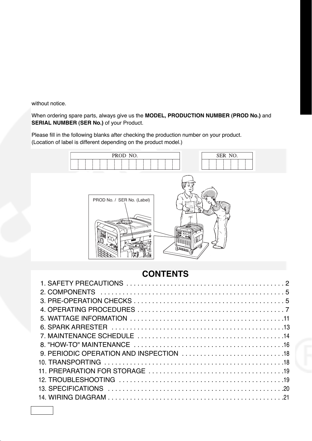
When ordering spare parts, always give us the MODEL, PRODUCTION NUMBER (PROD No.) and
SERIAL NUMBER (SER No.) of your Product.
Please fill in the following blanks after checking the production number on your product.
(Location of label is different depending on the product model.)
PROD No. / SER No. (Label)
ENGLISHFRANÇAISEESPAÑOL
CONTENTS
1. SAFETY PRECAUTIONS . . . . . . . . . . . . . . . . . . . . . . . . . . . . . . . . . . . . . . . . . . . 2
2. COMPONENTS . . . . . . . . . . . . . . . . . . . . . . . . . . . . . . . . . . . . . . . . . . . . . . . . . . 5
3. PRE-OPERATION CHECKS . . . . . . . . . . . . . . . . . . . . . . . . . . . . . . . . . . . . . . . . . 5
4. OPERATING PROCEDURES . . . . . . . . . . . . . . . . . . . . . . . . . . . . . . . . . . . . . . . . 7
5. WATTAGE INFORMATION . . . . . . . . . . . . . . . . . . . . . . . . . . . . . . . . . . . . . . . . . .
6. SPARK ARRESTER . . . . . . . . . . . . . . . . . . . . . . . . . . . . . . . . . . . . . . . . . . . . . . .
7. MAINTENANCE SCHEDULE . . . . . . . . . . . . . . . . . . . . . . . . . . . . . . . . . . . . . . . .
8. "HOW-TO" MAINTENANCE . . . . . . . . . . . . . . . . . . . . . . . . . . . . . . . . . . . . . . . . .
9. PERIODIC OPERATION AND INSPECTION . . . . . . . . . . . . . . . . . . . . . . . . . . . .
10
. TRANSPORTING . . . . . . . . . . . . . . . . . . . . . . . . . . . . . . . . . . . . . . . . . . . . . . . . .
11
. PREPARATION FOR STORAGE . . . . . . . . . . . . . . . . . . . . . . . . . . . . . . . . . . . . .
12
. TROUBLESHOOTING . . . . . . . . . . . . . . . . . . . . . . . . . . . . . . . . . . . . . . . . . . . . .
13
. SPECIFICATIONS . . . . . . . . . . . . . . . . . . . . . . . . . . . . . . . . . . . . . . . . . . . . . . . .
14
. WIRING DIAGRAM . . . . . . . . . . . . . . . . . . . . . . . . . . . . . . . . . . . . . . . . . . . . . . . .
NOTE
Please refer to the illustrations on the back page of the front cover or back cover
for Fig. 11to 66indicated in the sentence.
11
13
14
16
18
18
19
19
20
21
1
Page 8
1. SAFETY PRECAUTIONS
Please make sure you review each precaution carefully.
Pay special attention to statement preceded by the following words.
WARNING
ENGLISHFRANÇAISEESPAÑOL
CAUTION
“WARNING” indicates a strong possibility of severe personal injury or loss
of life if instructions are not followed.
“CAUTION” indicates a possibility of personal injury or
equipment damage if instructions are not followed.
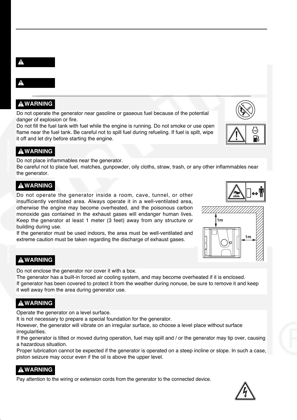
WARNING
Do not operate the generator near gasoline or gaseous fuel because of the potential
danger of explosion or fire.
Do not fill the fuel tank with fuel while the engine is running. Do not smoke or use open
flame near the fuel tank. Be careful not to spill fuel during refueling. If fuel is spilt, wipe
it off and let dry before starting the engine.
WARNING
Do not place inflammables near the generator.
Be careful not to place fuel, matches, gunpowder, oily cloths, straw, trash, or any other inflammables near
the generator.
WARNING
Do not operate the generator inside a room, cave, tunnel, or other
insufficiently ventilated area. Always operate it in a well-ventilated area,
otherwise the engine may become overheated, and the poisonous carbon
monoxide gas contained in the exhaust gases will endanger human lives.
Keep the generator at least 1 meter (3 feet) away from any structure or
building during use.
If the generator must be used indoors, the area must be well-ventilated and
extreme caution must be taken regarding the discharge of exhaust gases.
1m
1m
WARNING
Do not enclose the generator nor cover it with a box.
The generator has a built-in forced air cooling system, and may become overheated if it is enclosed.
If generator has been covered to protect it from the weather during nonuse, be sure to remove it and keep
it well away from the area during generator use.
WARNING
Operate the generator on a level surface.
It is not necessary to prepare a special foundation for the generator.
However, the generator will vibrate on an irregular surface, so choose a level place without surface
irregularities.
If the generator is tilted or moved during operation, fuel may spill and / or the generator may tip over, causing
a hazardous situation.
Proper lubrication cannot be expected if the generator is operated on a steep incline or slope. In such a case,
piston seizure may occur even if the oil is above the upper level.
WARNING
Pay attention to the wiring or extension cords from the generator to the connected device.
If the wire is under the generator or in contact with a vibrating part, it may break and
possibly cause a fire, generator burnout, or electric shock hazard.
Replace damaged or worn cords immediately.
2
Page 9
WARNING
Do not operate in rain, in wet or damp conditions, or with wet hands.
The operator may suffer severe electric shock if the generator is wet due to rain or snow.
WARNING
If wet, wipe and dry it well before starting. Do not pour water directly over the generator, nor wash it with
water.
WARNING
Be extremely careful that all necessary electrical grounding procedures are followed during each and every
use. Failure to do so can be fatal.
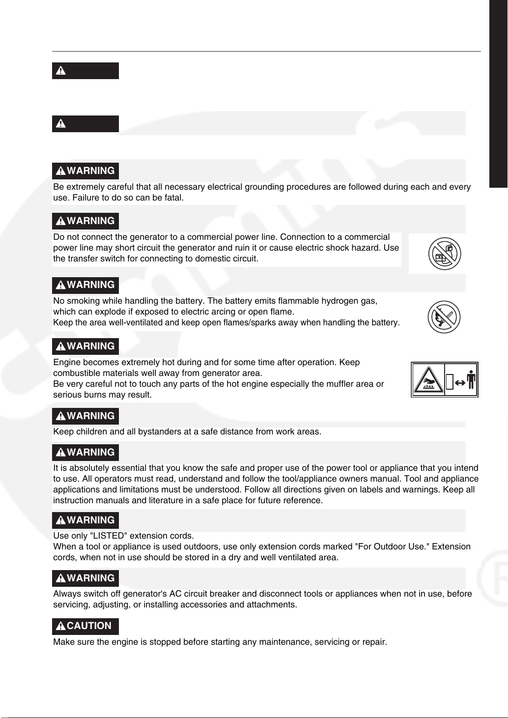
WARNING
Do not connect the generator to a commercial power line. Connection to a commercial
power line may short circuit the generator and ruin it or cause electric shock hazard. Use
the transfer switch for connecting to domestic circuit.
WARNING
No smoking while handling the battery. The battery emits flammable hydrogen gas,
which can explode if exposed to electric arcing or open flame.
Keep the area well-ventilated and keep open flames/sparks away when handling the battery.
WARNING
Engine becomes extremely hot during and for some time after operation. Keep
combustible materials well away from generator area.
Be very careful not to touch any parts of the hot engine especially the muffler area or
serious burns may result.
ENGLISHFRANÇAISEESPAÑOL
WARNING
Keep children and all bystanders at a safe distance from work areas.
WARNING
It is absolutely essential that you know the safe and proper use of the power tool or appliance that you intend
to use. All operators must read, understand and follow the tool/appliance owners manual. Tool and appliance
applications and limitations must be understood. Follow all directions given on labels and warnings. Keep all
instruction manuals and literature in a safe place for future reference.
WARNING
Use only "LISTED" extension cords.
When a tool or appliance is used outdoors, use only extension cords marked "For Outdoor Use." Extension
cords, when not in use should be stored in a dry and well ventilated area.
WARNING
Always switch off generator's AC circuit breaker and disconnect tools or appliances when not in use, before
servicing, adjusting, or installing accessories and attachments.
CAUTION
Make sure the engine is stopped before starting any maintenance, servicing or repair.
NOTE :
Make sure maintenance and repair of the generator set are performed by properly trained personnel only.
3
Page 10

Symbols and Meanings
In accordance with the European requirements (eec Directives), the specified symbols as shown in the
following table are used for the products and this instruction manual.
ENGLISHFRANÇAISEESPAÑOL
Read the operator's instruction manual.
Stay clear of the hot surface.
Exhaust gas is poisonous.
Do not operate in an unventilated room.
Stop the engine before refueling.
ON
(power and Engine)
OFF
(power and Engine)
Alternating current
IN-position of a
bistable push control
Protective earth
(ground)
Fuse
Fire, open light and smoking
prohibited.
Caution, risk of electric shock.
Do not connect the generator to
the commercial power lines.
HOT, avoid touching the hot area.
Engine start
(Electric start)
Engine stop
Gasoline
P r
f r
H max
Direct current
Plus ;
positive polarity
Minus ;
negative polarity
OUT-position of a
bistable push control
Rated power (kW)
Rated frequency (Hz)
Maximum site altitude
above sea-level (m)
COP
U r
T max
Engine oil
Add oil
Battery charging
condition
Choke ;
cold starting aid
Continuous power
Rated voltage (V)
Maximum ambient
temperature ( )
Fast
Slow
Fuel start
Fuel stop
COS
I r
r
Rated power factor
Rated current (A)
m Mass (kg)
4
Page 11

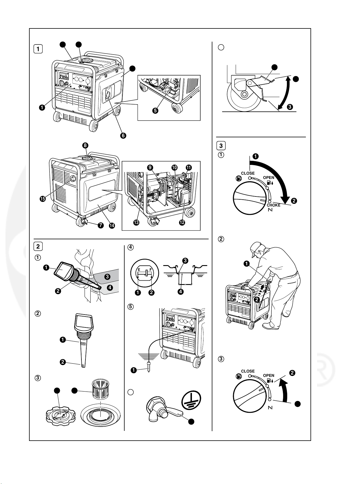
2. COMPONENTS (See Fig.1)
3. PRE−OPERATION CHECKS
NOTE
Please refer to the illustrations on the back page of
the front cover or back cover for Fig.
indicated in the sentence.
1 CONTROL PANEL
2 FUEL TANK
3 FUEL GAUGE
4 SIDE PANEL (R)
5 OIL DRAIN PLUG
6 RECOIL STARTER (HANDLE)
7 STOPPER
8 TANK CAP
9 FRAME
10 SPARK PLUG CAP
11 AIR CLEANER
12 FUEL STRAINER
13 BATTERY [Electric starter model]
14 OIL GAUGE (OIL FILLER)
15 SIDE PANEL (L)
16 EXHAUST OUTLET
1to6
(See Fig.
1. CHECK ENGINE OIL (See Fig.
Before checking or refilling oil, be sure generator
is located on stable and level surface with engine
stopped.
S
Remove oil filler cap and check the engine
oil level.
OIL GAUGE
1
2
3 UPPER LEVEL
4
S
If oil level is below the lower level line, refill
with suitable oil (see table) to upper level line.
Do not screw in the oil filler cap when
checking oil level.(See Fig. 2
1 UPPER LEVEL
2 LOWER LEVEL
S
Change oil if contaminated.
(See ”How−To” Maintenance.)
2
)
(See Fig. 2 −1)
OIL FILLER
LOWER LEVEL
2−1,2
−2)
Oil capacity :
Model Upper level
P3200ie . . . . . . 0.6 liters = .63 quarts
P4300ie . . . . . . 1.0 liters = 1.1 quarts
)
ENGLISHFRANÇAISEESPAÑOL
Recommended engine oil:
Use 4−stroke automotive detergent oil of API service
class SE or higher grade (SG, SH or SJ is
recommended). SAE 10W−30 or 10W−40 is
recommended for general, all−temperature use.
If single viscosity oil is used, select the appropriate
viscosity for the average temperature in your area.
5W
10W
Single grade
Multigrade
Ambient
temperature
20W
#20
#30
#40
10W−30
10W−40
5
Page 12

2. CHECK ENGINE FUEL (See Fig.
2−3, 4
4. CHECK GENERATOR SURROUNDINGS.
)
WARNING
Do not refuel while smoking or near open
flame or other such potential fire hazards.
ENGLISHFRANÇAISEESPAÑOL
Otherwise fire accident may occur.
S
Check fuel level at fuel level gauge.
(See Fig. 2
1 EMPTY (E)
2 FULL (F)
S
If fuel level is low, refill with unleaded
automotive gasoline.
S
Be sure to use the fuel filter screen on the fuel
filter neck.(See Fig. 2
1 FUEL FILTER SCREEN
2
TANK CAP
−4)
−3
)
Fuel tank capacity :
P3200ie . . . . . . 10.8 liters = 2.8 gal
P4300ie . . . . . . 12.8 liters = 3.4 gal
WARNING
Make sure you review each warning in
order to prevent fire hazard.
S
Do not refill tank while engine is
running or hot.
S
Before filling fuel, turn the engine
switch into STOP position.
S
Be careful not to admit dust, dirt, water
or other foreign objects Into fuel.
S
Wipe off spilled fuel thoroughly before
starting engine.
S
Keep open flames away.
3. CHECKING COMPONENT PARTS
Check following items before starting engine:
S
Fuel leakage from fuel hose, etc.
S
Bolts and nuts for looseness.
S
Components for damage or breakage.
S
Generator not resting on or against any
adjacent wiring.
WARNING
Make sure you review each warning in
order to prevent fire hazard.
S
Keep area clear of inflammables or
other hazardous materials.
S
Keep generator at least 3 feet (1 meter)
away from buildings or other structures.
S
Only operate generator in a dry, well
ventilated area.
S
Keep exhaust pipe clear of foreign objects.
S
Keep generator away from open flame.
No smoking!
S
Keep generator on a stable and level surface.
S
Do not block generator air vents with
paper or other material.
5. GROUNDING THE GENERATOR
S
To ground the generator to the earth, connect
the grounding lug of the generator to the
grounding spike driven into the earth or to the
conductor which has been already grounded
to the earth. (See Fig. 2
1 GROUNDING SPIKE
S
If such grounding conductor or grounding
electrode is unavailable, connect the
grounding lug of the generator to the
grounding terminal using electric tool or
appliance. (See Fig. 2
GROUND TERMINAL
1
−5)
−6)
6. NOTES ON INSTALLATION
S
Always be sure to place the generator on a
level surface, locking the wheel with the
stopper and/or chocking the wheels.
(See Fig. 2
STOPPER
1
2 UNLOCK
3
LOCK
−7)
6
Page 13

I.
STARTINO
I
Dm
nmt
Imluldrlng
mmd
THE
llnu
QENEMTOR
d&dh
md
@rn#a
plw
burrs
to
awing
npplrrnce
dqr
qpPln#
Ic)
1-1
PdIhs~hande$l~yurtil~Ihs
mlurnthe~Lbik~posdbn6ndplll
blisldy.
+
REmIL
@
PULL
rpplmem
grnw-
tha
W
-
(8-
STARTER
BRWY
whm
-rung
mW
oonn+eara
Ulr
gummar
rrd
h
prd
-rl
pdinl
imMaum
Fis
11~12.9
HRNME
rr
mat
nRlh
ow~d
mdhr
will
connwtd
up.
rn
mutt
in
wury,
bs
m.
lhbn
r
who~t~ngnmmbyrwoi~ee~,
dulsssy~d~hm'
pdt)#,
and
pull
ths
mtmbmr
I
"(ON')
handk.
Page 14

2. USING ELECTRIC POWER
WARNING
•
Make sure that the appliance is switched OFF before connecting it to the generator.
•
Do not move the generator while it is running.
ENGLISH
•
Be sure to ground the generator if the connected appliance is grounded. Failure to
ground unit may lead to electrical shock.
(1) CONTROL PANEL
P3200ie
FRANÇAISEESPAÑOL
P4300ie
1
1
2 3
568 97
2 3
568 97
4
4
CONTROL PANEL
1 MULTI MONITOR
2 AC RECEPTACLES (20A)
3 AC RECEPTACLES (30A)
8
4 GROUND TERMINAL
5 DC TERMINALS
6 DC CIRCUIT BREAKER
7
KEY SWITCH [Electric starter model]
8 ENGINE SWITCH
9 AC CIRCUIT BREAKER
Page 15

MULTI MONITOR
qq
LE display
MULTI MONITOR
1
Operation hour, voltage and frequency are indicated by
pressing the LE display changeover switch. In addition,
MULTI MONITOR
"O_Lod" (overload) will be indicated when the generator
is in the overload condition or appliance(s) will be out of order.
In this case, stop the engine immediately and check the
appliance and/or generator for overloading.
AUTO
P-SAVE
After the check and remedy, restarting the engine will
resume displaying in the normal manner.
ww
Operation hour lamp
8 7 6 5
Lamp (red) is turned on when changing over into operation hour indication in the LE display.
ee
Voltage lamp
Lamp (red) is turned on when changing over into voltage indication in the LE display.
rr
Frequency lamp
Lamp (red) is turned on when changing over into frequency indication in the LE display.
tt
LE display changeover switch
When depressing this switch, indication in LE display is changed over in turns;
operation hour → voltage → frequency → operation hour.
When starting the engine, operation hour is indicated in LE display at first.
2
Hours
V
Hz
3
4
ENGLISHFRANÇAISEESPAÑOL
yy
Auto-power saving switch
When depressing this switch, auto-power saving function is activated.
uu
Auto-power saving lamp
Lamp (green) is turned on while auto-power saving function is activated.
ii
Engine oil level warning lamp
When the engine oil level is lower than the specified level, the lamp is turned on.
Then engine will be stopped.
(2) AC APPLICATION (See Fig. 44-qq,ww)
(a) Make sure the voltage indicated in the LE display is the normal level (approx. 120V).
■■
This generator is thoroughly tested and adjusted in the factory.
If the generator does not produce the specified voltage, consult your nearest Cummins Onan dealer or
service shop.
(b) Turn off the switch(es) of the electrical appliance(s) before connecting to the generator.
(c) Insert the plug(s) of the electrical appliance(s) into the receptacle. (See Fig. 4-q)
■■
Check the amperage of the receptacles used referring to TABLE 1, and be sure not to take a current
exceeding the specified amperage.
■■
Be sure that the total wattage of all appliances does not exceed the rated output of the generator.
9
Page 16

Style Ampere
Receptacle
AC plug
Description
GFCI (Ground Fault
Circuit Interrupter)
Receptacle, duplex
Locking Receptacle
ENGLISHFRANÇAISEESPAÑOL
Up to 20A
Up to 30A
NEMA
5-20R
NEMA
5-30R
NEMA
5-20P
NEMA
5-30P
TABLE 1
WARNING
■■
To take power out from the TWIST LOCK
RECEPTACLE, insert the plug into the
receptacle, and turn it clockwise to the lock position. (See Fig. 44-ww)
■■
Be sure to ground the generator if the
connected electrical device is grounded.
CAUTION
Do not put foreign objects into the plug receptacle.
NOTE
When the "O_Lod" (overload) is indicated in the LE display, AC output is cut off on the grounds that the
generator operation is in overload condition or appliance(s) is out of order.
In this case, stop the engine immediately and check the appliance and/or generator for overloading.
After the check and remedy, restarting the engine will resume displaying in the normal manner.
(d) Turn on the switch of the appliance.
(3) DC APPLICATION (See Fig. 44-ee)
The DC terminal is used only for charging 12 volt batteries.
It provides up to 12V-8.3A (100W) of maximum power.
q Positive terminal (RED) w Negative terminal (BLACK)
CONNECTION OF CABLE :
■■
Connect positive terminal (red) on generator to positive (+) terminal on battery.
■■
Connect negative terminal (black) on generator to negative (-) terminal on battery.
SAFETY PRECAUTIONS WHILE CHARGING
■■
An explosive hydrogen gas is discharged through vent holes in the battery during the charging process.
Do not allow spark or open flame around the generator or battery during the charging process.
■■
Electrolyte fluid can burn eyes and clothing.
Be extremely careful to avoid contact. If injured, wash the affected area immediately with large quantities
of water and consult a doctor for treatment.
■■
When charging a large capacity battery or totally discharged battery, excessive current may force the DC
circuit breaker to turn off.
In such cases, use a battery charger to charge a large battery with AC output.
■■
Battery defects may cause the DC circuit breaker to turn off.
Check the battery before replacing the DC circuit breaker.
10
Page 17

5. WATTAGE INFORMATION
3. STOPPING THE GENERATOR
(a)
Turn off the power switch of the electric equipment
and unplug the cord from receptacle of the generator.
(b) Allow the engine about 3 minutes to cool down
at no load before stopping.
Turn the engine switch to the position " " (STOP).
(c)
(See Fig. 4-r)
q "" (RUN) w
"" (STOP)
(d) [Electric starter model]
Turn the key switch
to the " "(STOP)
STOP
ON
START
position.
4. OIL SENSOR (See Fig. 44-tt)
q OIL SENSOR
(a) The oil sensor detects the fall in oil level in the
crankcase and automatically stops the engine
when the oil level falls below a predetermined level.
(b)
When engine has stopped automatically, switch off
generator's AC circuit breaker, and check the oil level.
Refill engine oil to the upper level as instructed
on page 5 and restart the engine.
(c) If the engine does not start by usual
procedures, check the oil level.
CAUTION
Do not remove OIL SENSOR PROBE when
refilling with oil.
Remove oil filler cap on the opposite side
of carburetor.
starting
Some appliances need a "surge" of energy when
starting.
This means that the amount of electrical power
needed to start the appliance may exceed the
amount needed to maintain its use.
Electrical appliances and tools normally come with
a label indicating voltage, cycles / Hz, amperage
(amps) and electrical power needed to run the
appliance or tool.
Check with your nearest dealer or service center
with questions regarding power surge of certain
appliances or power tools.
■■
Electrical loads such as incandescent lamps
and hot plates require the same wattage to
start as is needed to maintain use.
■■
Loads such as fluorescent lamps require 1.2 to
2 times the indicated wattage during start-up.
■■
Loads for mercury lamps require 2 to 3 times
the indicated wattage during start-up.
■■
Electrical motors require a large starting
current. Power requirements depend on the
type of motor and its use. Once enough
"surge" is attained to start the motor, the
appliance will require only 50% to 30% of the
wattage to continue running.
■■
Most electrical tools require 1.2 to 3 times their
wattage for running under load during use. For
example, a 5000 watt generator can power a
1800 to 4000 watt electrical tool.
■■
Loads such as submersible pumps and air
compressors require a very large force to start.
They need 3 to 5 times the normal running
wattage in order to start.
For example, a 5000 watt generator would only
be able to drive a 1000 to 1700 watt pump.
ENGLISHFRANÇAISEESPAÑOL
11
Page 18

NOTE
The following wattage chart is general guide only. Refer to your specific appliance for
correct wattage.
To determine the total wattage required to run a particular electrical appliance or tool, multiply the voltage
figure of the appliance/tool by the amperage (amps) figure of same. The voltage and amperage (amps)
ENGLISHFRANÇAISEESPAÑOL
information can be found on a name plate which is normally attached to electrical appliances and tools.
Applicable Wattage (W)
Applications
P3200ie
60Hz
P4300ie
Incandescent lamp, Heater approx. 2800
Fluorescent lamp, Electric tool approx. 1400
Mercury lamp approx. 1000
Pump, Compressor approx. 600
approx. 3800
approx. 1900
approx. 1600
approx. 800
VOLTAGE DROP IN ELECTRIC EXTENSION CORDS
When a long electric extension cord is used to connect an appliance or tool to the generator, a certain
amount of voltage drop or loss occurs in the extension cord which reduces the effective voltage available for
the appliance or tool.
The chart below has been prepared to illustrate the approximate voltage loss when an extension
(approx. 100 meters) is used to connect an appliance or tool to the generator.
Nominal
cross
A.W.G.
section
2
mm
No. A 1A 3A 5A 8A 10A 12A 15A
0.75 18 7 30/0.18 2.477 2.5V 8V
Allowable
current
No.of strands
/ strands dia.
No./mm
Resistance
Ω/100m
Current Amp.
12.5V
─ ─ ─ ─
1.27 16 12 50/0.16 1.486 1.5V 5V 7.5V 12V 15V 18V
2.0 14 17 37/0.26 0.952 1V 3V 5V 8V 10V 12V 15V
cord of 300 feet
─
3.5 12 to 10 23 45/0.32 0.517
5.5 10 to 8 35 70/0.32 0.332
12
1.5V 2.5V 4V 5V 6.5V 7.5V
─
1V 2V 2.5V 3.5V 4V 5V
─
Voltage drop
Page 19

6. SPARK ARRESTER
Always use the product with a spark arrester.
use of a spark arrester. Please check your local laws and regulations before operating your
The spark arrester must be cleaned regularly to keep it functioning as designed.
A clogged spark arrester :
•
Prevents the flow of exhaust gas
•
Reduces engine output
•
Increases fuel consumption
•
Makes starting difficult
If the engine has been running, the muffler and the spark arrester will be very hot. Allow the muffler to cool
before cleaning the spark arrester.
Some areas require the
product
.
How to remove the spark arrester
1. Remove the flange bolts from the muffler cover and
remove the muffler cover.
2. Remove the special screw from the spark arrester
and remove the spark arrester from the muffler.
SPARK
ARRESTER
SCREEN
NUT
MUFFLER
TAIL SCREEN
SCREW
TAIL SCREEN COVER
ENGLISHFRANÇAISEESPAÑOL
Clean the spark arrester screen
Use a brush to remove carbon deposits from the spark
arrester screen.
Be careful to avoid damaging the screen.
The spark arrester must be free of breaks and holes.
Replace the spark arrester if it is damaged.
Install the spark arrester, and muffler protector in the
reverse order of disassembly.
SPARK ARRESTER SCREEN
13
Page 20

7. MAINTENANCE SCHEDULE
MAINTENANCE, REPLACEMENT OR REPAIR OF THE EMISSION CONTROL DEVICES
AND SYSTEMS MAY BE PERFORMED BY ANY NONROAD ENGINE REPAIR
ESTABLISHMENT OR INDIVIDUAL.
DAILY INSPECTION
Before running the generator, check the following service items:
ENGLISHFRANÇAISE
Safe surroundings
Leakage of gasoline and engine oil
Enough clean engine oil
AC and DC terminals for damage
Enough gasoline
Excessive vibration,noise
Clean air cleaner element
Loose or broken bolts and nuts
PERIODIC MAINTENANCE
Periodic maintenance is vital to safe and efficient operation of your generator.
Check the table below for periodic maintenance intervals.
IT IS ALSO NECESSARY FOR THE USER OF THIS GENERATOR TO
CONDUCT THE MAINTENANCE AND ADJUSTMENTS ON THE EMISSION-
RELATED PARTS LISTED BELOW TO KEEP THE EMISSION CONTROL
SYSTEM EFFECTIVE.
The emission control system consists of the following parts :
(1) Carburetor and internal parts
(2) Cold start enrichment system,
if applicable
(3) Intake manifold, if applicable
(4) Air cleaner elements
The maintenance schedule indicated in the table is based on the normal generator operation. Should the
generator be operated in extremely dusty conditions or in heavier loading conditions, the maintenance intervals
must be shortened depending on the contamination of oil, clogging of filter elements, wear of parts, and so on.
(5) Spark plug
(6) Magneto or electronic ignition
system
(7) Spark advance/retard
system, if applicable
(8) Exhaust manifold, if
applicable
(9) Hoses, belts, connectors, and
assemblies
14
Page 21

Periodic Maintenance Schedule table
Maintenance Items
Clean generator and check nuts & bolts
Check and refill engine oil
Change engine oil (*Note1)
Clean spark plug
Clean air cleaner
Replace air cleaner element
Clean fuel filter
Clean and adjust spark plug and electrodes
Replace spark plug
Clean spark arrester
Remove carbon from cylinder head (*Note 2)
Check and adjust valve clearance (*Note 2)
Clean and adjust carburetor (*Note 2)
Every
8 hours
(Daily)
Every
50 hours
(Weekly)
Every
200 hours
(Monthly)
●(Daily)
●(Refill daily up to upper level)
●(Initial
20 hours)
●(Every
100 hours)
●
●
●
●
●
●(Every 100 hours)
Every
500
hours
●
●
●
●
Every
1000
hours
ENGLISHFRANÇAISEESPAÑOL
Replace fuel lines
Overhaul engine (*Note 2)
Check AC receptacles
Check DC terminal
Check engine switch
Check multi monitor
Check rotor
Check stator
Replace engine mount
*Note: 1. Initial oil change should be performed after first twenty (20) hours of operation. Thereafter
change oil every hundred (100) hours.
Before changing oil, check for a suitable way to dispose of old oil.
Do not pour it down into sewage drains, onto garden soil or into open streams. Your local zoning
or environmental regulations will give you more detailed instructions on proper disposal.
*Note: 2. As to the procedures for these items, please refer to the SERVICE MANUAL or consult your
nearest Cummins Onan service dealer.
●(Daily)
●(Daily)
●(Daily)
●(Daily)
● (Yearly)
●
●
●
●
15
Page 22

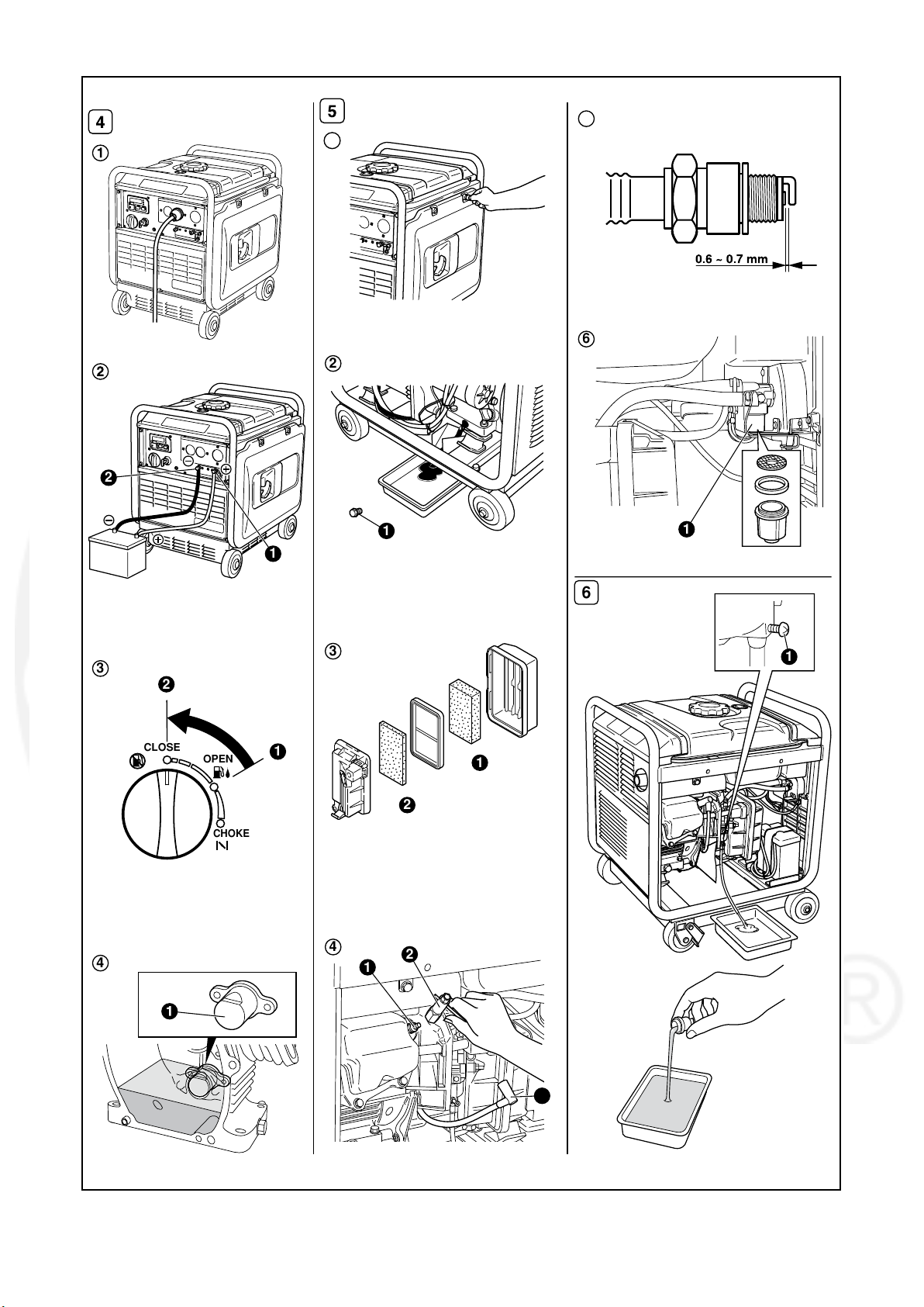
8. "HOW-TO" MAINTENANCE
(See Fig.
5
)
CAUTION
Make sure the engine is stopped before
starting any maintenance, servicing or
ENGLISH
repair.
NOTE
It is recommended to use hearing protection
when performing operation, maintenance
and repair of the generator set.
1.
SIDE PANEL (L.R.)
To access the following items for servicing, take the
applicable side cover out by removing the screw
with screwdriver or coin.
LH-side cover ---- Oil level gauge, Air cleaner,
FRANÇAISEESPAÑOL
RH-side cover ---- Oil drain screw etc.
Spark plug, Battery etc.
(See Fig. 5-1)
2. ENGINE OIL CHANGE (See Fig. 5-2)
•
Change engine oil every 50 hours.
(For new engine, change oil after 20 hours.)
(a) Drain oil by removing the drain plug and the oil
filler cap while the engine is warm.
1 OIL DRAIN PLUG
(b) Reinstall the drain plug and fill the engine with
oil until it reaches the upper level on the oil filler cap.
•
Use fresh and high quality lubricating oil to the
specified level as directed on page 5.
If contaminated or deteriorated oil is used or the
quantity of the engine oil is not sufficient, the
engine damage will result and its life will be
greatly shortened.
3. SERVICING THE AIR CLEANER
5
(See Fig.
Maintaining an air cleaner in proper condition is
very important.
Dirt induced through improperly installed,
improperly serviced or inadequate elements
damages and wears out engines. Keep the
element always clean.
(a)
Unhook the cover and remove the cleaner element.
1 2 ELEMENT (Urethane form)
(b) Urethane form : Wash the element with fresh
water. Squeeze out the water then dry the
element. (Do not twist.)
-3)
16
4. CLEANING AND ADJUSTING
5
SPARK PLUG (See Fig.
(a) If the plug is contaminated with carbon, remove
it using a plug cleaner or wire brush.
(b) Adjust the electrode gap to 0.6 to 0.7 mm (0.024
to 0.028 in.).
1 SPARK PLUG
2 PLUG WRENCH
3 SPARK PLUG CAP
-4,5)
Model Spark plug
P3200ie
P4300ie
NGK BR-6HS
(CHAMPION RL86C)
5. CLEANING FUEL STRAINER
5
(See Fig.
Dirt and water in the fuel are removed by the fuel
strainer.
1 FUEL STRAINER CUP
(a) Remove the strainer cup and throw away water
and dirt.
(b) Clean the screen and strainer cup with gasoline.
(c) Tightly fasten the cup to main body, making sure
to avoid fuel leak.
-6)
6. BATTERY INSTALLATION
Recommended Battery (Lead-acid battery)
P3200ie : 12V-6A・h or larger.
P4300ie : 12V-12A・h or larger.
(Applicable Battery Make & Model)
P3200ie P4300ie
YUASA
GS
INTERSTATE
GNB
SEARS
(a) Attach terminals to a lead-acid battery already
charged. Mount the battery onto the position as
specified below, with its terminals facing inward.
YTX7L-BS
GTX7L-BS
YTX7L-BS
7L-BS
44024
YB12AL-A2
GM12AZ-3A-2
or CB12AL-A
YB12AL-A
12AL-A
44052
Page 23

(b) Insert each long bolt through the specified hole, its tip pointing outward.
(c) Put the supporting arm on the long bolts and tighten with the butterfly nuts.
(Push the lead-acid battery all the way inward.)
(d) Arrange the wiring so that it won't be damaged by possible vibration caused by the engine.
(e) Only after checking that the engine's starter key is in the "OFF" position, securely connect the red cable,
to the positive (+) terminal. And then connect the other cable to the negative (-) terminal.
Red cable : to the (+) terminal
Black cable : to the (
-
) terminal
CAUTION
Should the connection be made in incorrect manner, the engine will be broken.
1
Battery Base
2
Flange Bolt
3
Screw
4
Battery Band
5
Bolt and Nut
Battery cover
6
5
Accessory parts
4
6
1
3
ENGLISHFRANÇAISEESPAÑOL
RED
CABLE
LESS THAN
131 mm [5.2 in.] ( P3200ie)
162 mm [6.4 in.] (P4300ie)
LESS THAN
114 mm [4.5 in.] (P3200ie)
136 mm [5.4 in.] (P4300ie)
RED CABLE
2
LESS THAN
71 mm [2.8 in.] (P3200ie)
82 mm [3.2 in.] (P4300ie)
17
Page 24

9.
PERlODfC
INSPECTlON
When
fumhhl~
the
OPERATION
gmerPdor
as
s-~y
AND
10,
TRAMSPORmNG
When
the
he!
(a)
Turn
position.
tramporling
(gasdine)
the
the
is
engine
swltch
generator,
dmW
to
from
the
make
the
'
@
sure
tank.
(STOP)
that
I
hmp
--iit*plepw
position
that
or
with
of
?he
generator
fall
down.
tie-downs
the
tmnsport
Secw
as
vehicle
canno!
the
generator
be
moved
necessary.
so
Page 25

11. PREPARATION FOR STORAGE (See Fig. 66)
The following procedures should be followed prior to storage of your generator for periods of 6 months or longer.
■■
Drain fuel from fuel tank carefully by disconnecting the fuel line.
Gasoline left in the fuel tank will eventually deteriorate making engine-starting difficult.
■■
Remove the drain screw of the carburetor.(See Fig. 6-q)
q DRAIN SCREW
■■
Change engine oil.
■■
Check for loose bolts and screws, tighten them if necessary.
■■
Clean generator thoroughly with oiled cloth. Spray with preservative if available. NEVER USE WATER
TO CLEAN GENERATOR !
■■
Pull starter handle until resistance is felt, leaving handle in that position.
■■
Store generator in a well ventilated, low humidity area.
12. TROUBLESHOOTING
When generator engine fails to start after several attempts, or if no electricity is available at the output
socket, check the following chart. If your generator still fails to start or generate electricity, contact your
nearest Cummins Onan dealer or service shop for further information or corrective procedures.
When Engine Fails to Start:
ENGLISHFRANÇAISEESPAÑOL
Check if engine switch is in its proper position.
Check fuel level.
Check to make sure generator is not
connected to an appliance.
Check spark plug for loose spark plug cap.
Check spark plug for contamination.
Check engine oil level.
When No Electricity Is Generated at Receptacle :
Check if the "O_Lod"(overload) is indicated
in the Multi Monitor.
Check if the DC circuit breaker is turned off.
Check AC receptacle and DC terminals for
loose connection.
Turn engine switch to " "(CHOKE) position.
If empty, refill fuel tank making sure not to overfill.
If connected, turn off the power switch on the
connected appliance and unplug.
If loose, push spark plug cap back into place.
Remove spark plug and clean electrode.
If the engine oil level is low, add the oil to the
upper level line on the oil gauge.
Stop the engine and check the appliance
and/or generator for overloading.
Depress the circuit breaker into ON position,
after making sure the charging current level
is proper and the battery is in the normal
condition.
Secure connection if necessary.
Check to see if engine starting was
attempted with appliances already
connected to generator.
Turn off switch on the appliance, and
disconnect cable from receptacle. Reconnect
after generator has been started properly.
19
Page 26

13. SPECIFICATIONS
HSILGNEESIAÇNARFLOÑAPSE
rotareneGenignE
MODEL
Type Multiple revolving field magnet type
AC Output
Rated output
Rated voltage V
Rated current A
Frequency Hz
DC Output
Rated voltage V
Rated current A
Insulation class
Insulation endurance
Model
Type
Displacement mL (cu.in.)
Maximum output kW / rpm
Continuous output
Fuel Automobile unleaded gasoline
VA
W
kW / rpm
100 (Battery charge only)Rated output
10 MΩ and higher at 500 VInsulation resistance
Revolving field of permanent magnet.Exciting system
EX27
Forced air-cooled,4-cycle,single cylinder OHC type gasoline engine
65 (16.17)
5.1 / 3,63.7 / 3,600
P3200ie P4300ie
2,800
120
23.3 31.7
60
1.0Power factor
12
8.3
B
1,250 V for 1minute
EX21
211 (12.87)
4.8 / 3,600
3,800
6.3 / 3,600
Fuel tank capacity
L (U.S. gal)
Starting system Recoil starter
Ground system Neutral ground
noisnemiD
Length mm (in.)
Width mm (in.)
Height
mm (in.)
74 (163.1)Weight kg (lb) 59 (130)
Valve Clearance
(Intake & Exhaust) mm(in.)
Note : Adjust the valve clearance while the engine is cold.
10.8 (2.84) 12.8 (3.37)
537 (21.1)
482 (18.9)
583 (22.9)
0.1± 0.03 (0.0039± 0.0012)
20
Electric / Recoil starter
580 (22.8)
527 (20.8)
618 (24.3)
Page 27

ENGLISHFRANÇAISEESPAÑOL
21
Page 28

P3200ie / P4300ie (60Hz-120V)
ENGLISHFRANÇAISEESPAÑOL
DC
winding
Sub coil 1
Sub coil 2
GENERATOR
Main coil
Stepping motor
Oil level
sensor
Starting
motor
M
Diode
rectifier
Ignition coil
Spark
plug
Org
Gry
Brn
Brn
W
W
Grn/Y
R
W
Blu
DC circuit breaker
Org
Org
Gry
Brn
Brn
R
W
Blu
Grn
Blu
Pur
Gry
Org
Blk
Blu
Grn/Y
Y
Y
W
Blu
INV&E/G C/U
Engine
switch
W
R
W
Fuse10A
R
W
R
DC output
terminal
Regulator
R
Grn/Y
Grn/Y
W
W
Blk
Blu
Grn
Blu
MONITOR C/U
Y
Brn
Brn
Blk
AC circuit
breaker
RR
R
W
AC circuit
breaker
R
AC
receptacle
R
W
M-
ST
L.IG
M+
B
Key switch
Earth plate
Grn/Y
AC circuit
breaker
R
AC
receptacle
CONTROL PANEL
Grn/Y
Earth
(ground)
terminal
Grn/Y
W
W
Org
R
Grn/Y
22
ENGINE
Wiring color cord
Blk : Black
Blk/W : Black/White
Blu : Blue
Battery
Blk
LBlu : Light blue
Brn : Brown
Brn/W : Brown/White
Grn : Green
Grn/W : Green/White
Org : Orange
RELAY
Gry : Gray
R : Red
W : White
Y : Yellow
W/Blk : White/Black
Grn/Y : Green/Yellow
Pur : Purple
Page 29

Cummins Power Generation
1400 73rd Ave. NE
Minneapolis, MN 55432 USA
Phone 1 763 574 5000
Toll-free 1 800 888 6626
Fax 1 763 574 5298
Email www.cumminsonan.com/contact
www.cumminsonan.com
CumminsR, OnanR, the “C” logo, and “Performance you rely on.”
are trademarks of Cummins Inc.
E2007 Cummins Power Generation, Inc. All rights reserved.
 Loading...