

Page 1

TECHNICAL MANUAL
MASHINESOFT.COM
09120146259
OPERATOR' S, UNIT, INTERMEDIATE
(DS) AND INTERMEDIATE (GS)
MAINTENANCE MANUAL
FOR
ENGINE, DIESEL,
CUMMINS MODEL NTA - 855 -L4
NSN 2815-01-216-0939
TM 5-2815-233-14
(Circle C) Copyright 1983
HEADQUARTERS, DEPARTMENT OF THE ARMY
Cummins Engine Company, Inc.
Used by Permission
25 JULY 1986
Page 2

TM 5-2815-233-14
MASHINESOFT.COM
09120146259
TECHNICAL MANUAL HEADQUARTERS
DEPARTMENT OF THE ARMY
NO 5-2815-233-14 WASHINGTON, D. C., 25 July 1986
OPERATOR'S UNIT, INTERMEDIATE
(DS) AND INTERMEDIATE (GS)
MAINTENANCE MANUAL
ENGINE, DIESEL,
CUMMINS MODEL NTA-855-L4
NSN 2815-01-216-0939
NOTE:
This manual is printed in two parts as follows:
Part 1 consisting of Table of Contents, Operation and Maintenance instructions.
Part 2 consisting of a separate Table of Contents and Repair instructions.
REPORTING ERRORS AND RECOMMENDING IMPROVEMENTS
You can help improve this manual. If you find any mistake or if you know of a way to
improve the procedures, please let us know. Mail your letter, DA Form 2028
(Recommended Changes to Publications and Blank Forms), or DA Form 2028-2 located
in the back of this manual direct to: Commander, U.S. Army Troop Support Command,
ATTN: AMSTR-MCTS, 4300 Goodfellow Boulevard, St. Louis, MO 63120-1798.
A reply will be furnished directly to you.
TABLE OF CONTECTS
Operating Instructions
Specifications and Torque
Prestarting Instructions........................................1-1
Starting the Engine..............................................1-3
Engine Warm-Up................................................1-6
Engine Speeds....................................................1-6
Engine Exhaust...................................................1-7
High Altitude Operation.......................................1-7
Engine Shutdown................................................1-7
Cold Weather Protection.....................................1-8
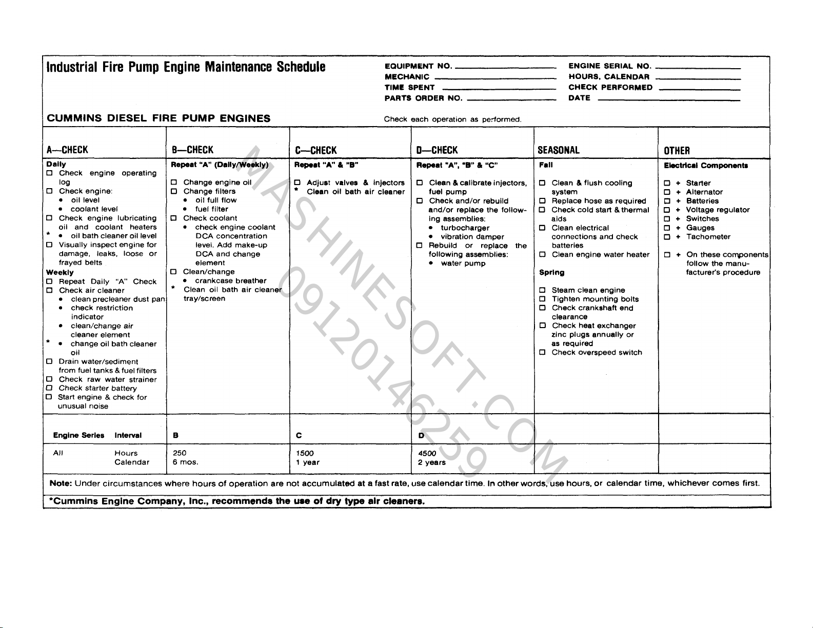
Industrial Fire Pump Engines..............................1-11
Maintenance Operations
Schedule.............................................................2-2
Check Sheet.......................................................2-3
A Checks - Daily.................................................2-7
A Checks - Weekly..............................................2-11
B Checks............................................................2-15
C Checks............................................................2-34
D Checks............................................................2-50
Seasonal Maintenance Checks...........................2-54
Lubricating Oil.....................................................3-1
Grease................................................................3-5
Fuel 011..............................................................3-6
Coolant...............................................................3-7
Torque Speclflcatlons..........................................3-8
Trouble-Shooting
Description..........................................................4-1
Chart...................................................................4-2
Index
Intro pg
Page 3

Part I
MASHINESOFT.COM
09120146259
OPERATION AND MAINTENANCE
TM 5-2815-233-14
a
Page 4

Operation and Maintenance Manual Cummins Diesel
MASHINESOFT.COM
09120146259
Engines
Agricultural
Construction
Industrial
Industiral Fire Pump
Logging
Mining
Railway
Generator
TM 5-2815-233-14
Copyright © 1980
Cummins Engine Company, Inc. Bulletin 3379052-09 Printed 10/80
b
Page 5

Foreword
MASHINESOFT.COM
09120146259
This is an engine operation and maintenance manual, not a
repair manual. The design of Cummins Engines makes it
possible to replace worn or damaged parts with new or rebuilt
parts with a minimum of down time. Contact the nearest
Cummins Distributor for parts replacement as they are equipped
and have well informed, trained personnel to perform this
service. If your shop is properly equipped to perform either
maintenance, unit replacement and/or complete engine rebuild,
contact the nearest Cummins Distributors to obtain available
repair manuals and arrange for training of personnel.
For model identification of an engine, check the dataplate. The
letter and number code indicates breathing (naturally aspirated
except when letter "T" for turbocharged is present), cubic inch
displacement, application and maximum rated horsepower.
Examples:
TM 5-2815-233-14
NTA-855-370 V-903-320
N=4 valve head V=Type engine
T=Turbocharger 903=Cubic Inch
A=Aftercooled Displacement
370=Maximum rated 320=Maximum Rated
horsepower horsepower
Cummins Engine Company, Inc.
Columbus, Indiana, U.S.A.
c/(d Blank)
Page 6
Operating
MASHINESOFT.COM
09120146259
Instructions
General-All Applications
New and Rebuilt Engines Break-In
Cummins engines are run-in on dynamometers before
being shipped from the factory and are ready to be put
to work in applications such as emergency fire trucks,
rail car applications and generator sets. In other
applications, the engine can be put to work, but the
operator has an opportunity to establish conditions for
optimum service life during initial 100 hours of service
by:
1. Operating as much as possible at three-quarter
throttle of load range.
2. Avoiding operation for long periods at engine
idle speeds, or at the maximum horsepower
levels in excess of five minutes.
3. Developing the habit of watching the engine
instruments closely during operation and letting
up on the throttle if the oil temperature reaches
200° F [121° C] or the coolant temperature
exceeds 200° F [93° F].
4. Operating with a power requirement that allows
acceleration to governed speed when conditions
require more power.
The engine operator must assume the responsibility of
engine care while the engine is being operated. There
are comparatively few rules which the operator must
observe to get the best service from a Cummins Diesel.
4. If the injector and valve or other adjustments
have been disturbed by any maintenance work,
check to be sure they have been properly
adjusted before starting the engine.
Priming the Lubricating System
Note: On turbocharged engines, remove the oil inlet
line from the turbocharger and prelubricate the bearing
by adding 2 to 3 oz. [50 to 60 cc] of clean lubricating oil.
Reconnect the oil supply line.
1. Fill the crankcase to the "L" (low) mark on the
dipstick. See Lubricating Oil Specifications,
Section 3.
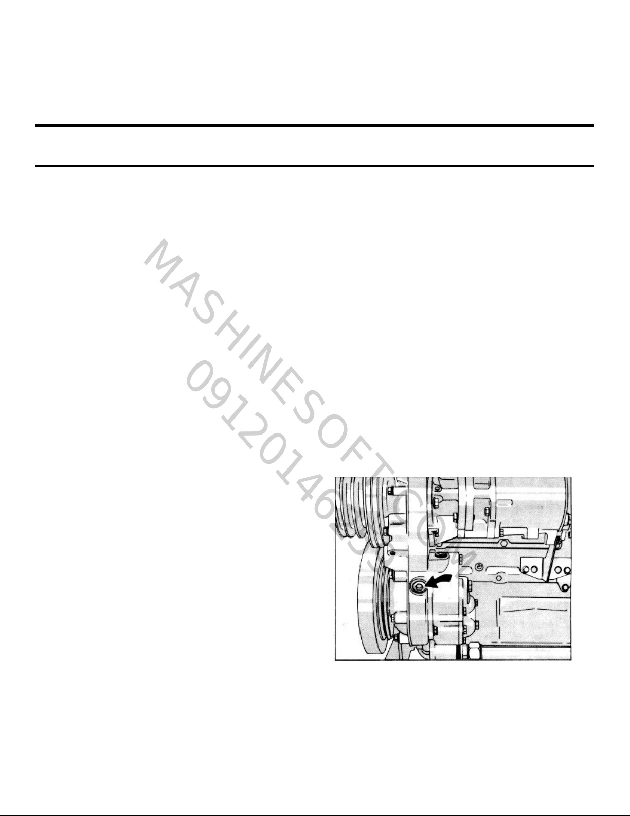
2. Remove the plug from the lubricating oil
crossover passage on NH/NT-855 Engines, Fig.
1-1. Remove the plug from the head of the
lubricating oil filter housing on V Engines, Fig's.
1-2, 1-3, 1-4, 1-5 and 1-6. On KT/KTA-1150
Engines, remove the plug from the front of the
oil cooler housing, Fig. 1-7.
Operating Instructions
5. Checking the oil level every 8 to 10 hours during the
break-in period.
New or Rebuilt Engines
Pre-Starting Instructions - First Time
Priming The Fuel System
1. Fill the fuel filter with clean No. 2 diesel fuel oil
meeting the specifications outlined in Section 3.
2. Remove the fuel pump suction line and wet the
gear pump gears with clean lubricating oil.
3. Check and fill the fuel tanks.
1-1
Fig. 1-1 (OM1001L). Lubricating system priming point-
NT-855 C.I.D. Engine
Page 7
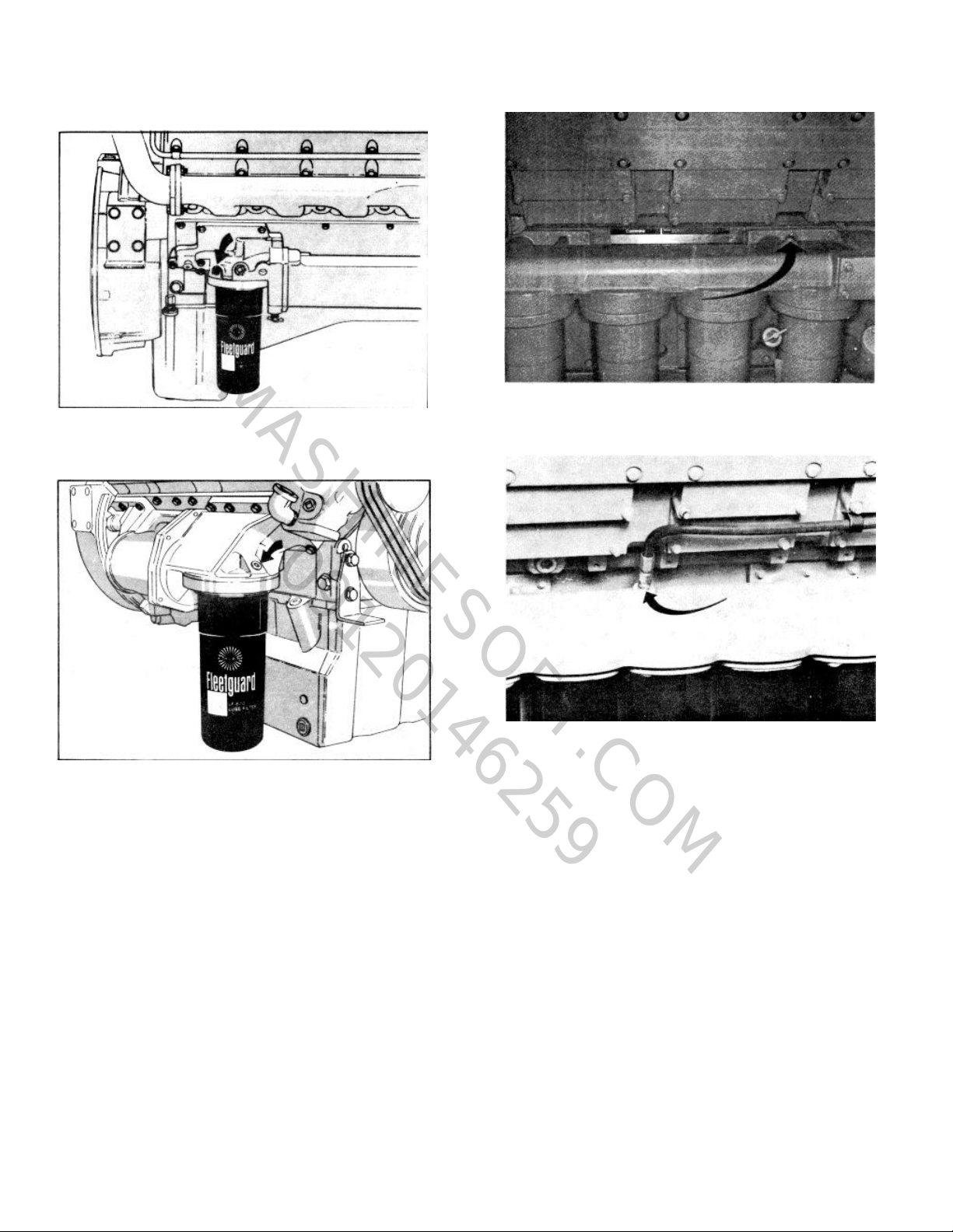
Fig. 1-2 (OM1002L). Lubricating system priming point-
MASHINESOFT.COM
09120146259
VT-903 C.I.D. Engine
Operation and Maintenance
Construction and Industrial
Fig. 1-4 (K21902). Lubricating system priming point
KT(A)-2300 Engine
Fig. 1-5 (OM202). Lubricating system priming point -
KTA-3067 Engine
Fig. 1-3 (OM1003L). Lubricating system priming point--
V/VT-555 C.I.D. Engine
Caution: Do not prime the engine lubricating
system from the by-pass filter.
3. Connect a hand- or motor-driven priming pump
line from a source of clean lubricating oil to the
plug boss in the housing.
4. Prime until a 30 psi [207 kPa] minimum
pressure is obtained.
5. Crank the engine at least 15 seconds (with fuel
shut-off valve closed or disconnected to prevent
starting), while maintaining the external oil pressure at a minimum of 15 psi [103 kPa].
6. Remove the external oil supply and replace the
plug.
Warning: Clean the area of any lubricating oil
spilled while priming or filling the crankcase.
7. Fill the crankcase to the "H" (high) mark on the
dipstick with oil meeting specifications, listed in
Section 3. No change in oil viscosity or type is
needed for new or newly rebuilt engines.
A dipstick oil gauge is located on the side of the engine,
Fig. 1-8. The dipstick has an "H" (high) (1) and "L" (low)
(2) level mark to indicate lubricating oil supply. The
dipstick must be kept with the oil pan, or engine, with
which it was originally supplied. Cummins oil pans differ
in capacity with different type installations and oil pan
part numbers. Check the dipstick calibration. If in
doubt, your Cummins Distributor
1-2
Page 8
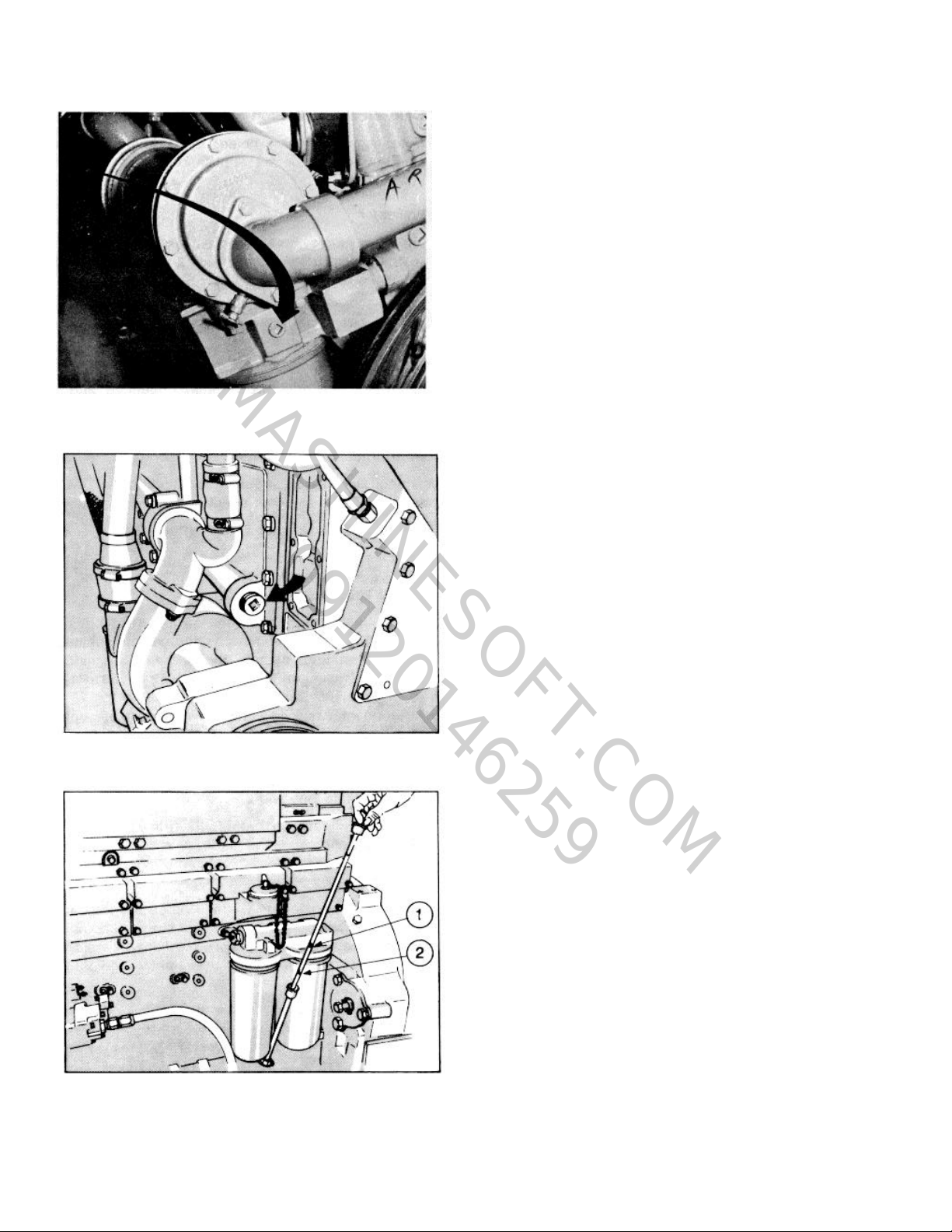
Fig. 1-6 (V41816). Lubricating system priming point - V-
MASHINESOFT.COM
09120146259
1710 Engine
OPERATING INSTRUCTIONS
can verify that you have the proper oil pan and dip-stick
calibration.
Check Hydraulic Governor
Many engines used in stationary power applications are
equipped with hydraulic-governed fuel pumps which use
lubricating oil as an energy medium, same weight as
used in the engine. Oil level in the governor sump must
be at the full mark on the dipstick.
Note: Engine applications in a cold environment should
use a lighter weight oil in the governor sump.
Check Air Connections
Check the air connections to the compressor and the air
equipment, as used, and to the air cleaners and air
crossovers to assure that they all are secure and have
no damage.
Check Engine Coolant Supply
1. Remove the radiator or heat exchanger cap and
check the engine coolant supply. Add coolant
as needed.
2. Make a visual check for leaks and open the
water filter shut-off valves.
Starting the Engine
Starting requires that clean air and fuel be supplied to
the combustion chambers in the proper quantities at the
correct time.
Normal Starting Procedure
Fig. 1-7 (OM1004L). Lubricating system priming pointKT/KTA C.I.D. Engine
Warning: Before starting be sure that everyone is
clear of the engine and equipment.
If the fuel system is equipped with an overspeed stop,
push the "Reset" button before attempting to start the
engine.
1. On units equipped with an air activated prelube
device, open the air valve to activate the piston
in the prelube device which will lubricate all
moving parts in the engine.
Note: On engines equipped with an oil pressure safety
switch, hold the fuel by-pass switch in the "start" position until the engine oil pressure reaches 7 to 10 psi [48
to 69 kPa]; then, move it to the "run" position.
2. Set the throttle for idle speed and disengage the
driven unit.
Fig. 1-8 (OM1005L). Checking engine oil level
Operating Instructions
Caution: Protect the turbocharger during start-up
by not opening the throttle or accelerating above
1000
1-3
Page 9
Operation and Maintenance
MASHINESOFT.COM
09120146259
Construction and Industrial
rpm until the idle speed oil pressure registers on
the gauge.
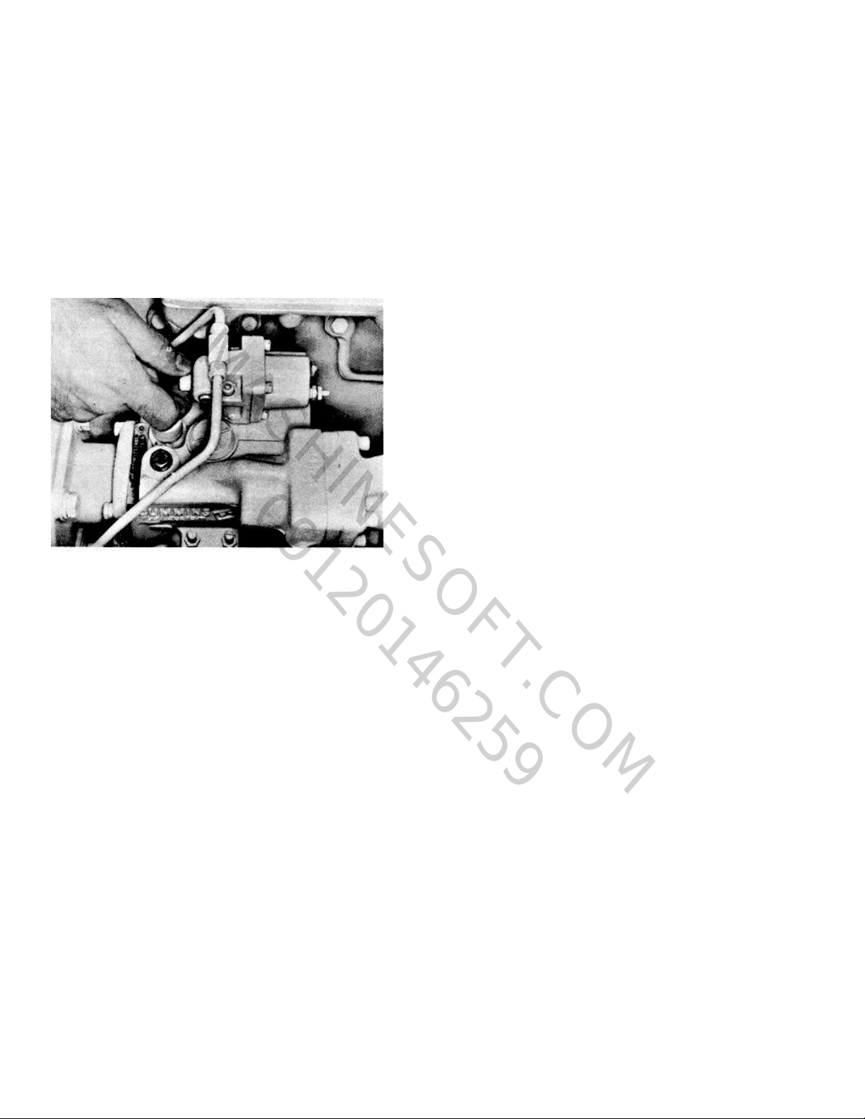
3. Open the manual fuel shut-down valve, if so
equipped. Fig. 1-9. Electric shut-down valves operate
as the switch is turned on. A manual override knob
provided on the forward end of the electric shut-down
valve allows the valve to be opened in case of an
electric power failure. To use, turn fully clockwise;
return it to the run position after an electric repair.
Fig. 1-9 (V21970). Using manual override knob
4. Pull the compression release (if so equipped)
and press the starter button or turn the switchkey to the "start" position. After three or four
Caution: To prevent permanent cranking motor
damage, do not crank the engine for more than 30
seconds continuously. If the engine does not fire
within the first 30 seconds, wait one to two minutes
before recranking.
5. At the initial start or after oil or filter changes
seconds of cranking, close the compression
release (if so equipped) and continue to crank
until the engine fires.
and after the engine has run for a few minutes,
shut it down and wait 15 minutes for the oil to
drain back into the pan. Check the engine oil
level again; add oil as necessary to bring the oil
level to the "H" mark on the dipstick. The drop
in oil level is due to absorption by the oil filters.
Never operate the engine with the oil level
below the low level mark or above the high level
mark.
Cold-Weather Starting
Note: A water jacket heater is recommended for stand-
by generator set applications installed in a cold climate
Preheater
The glow plug system supplies heat to the cylinders so
that compression temperatures are sufficient to ignite
the fuel.
To aid in starting the engine when the temperature is
50°F [10.0°C] or below, an intake air preheater is
available.
Preheater equipment consists of a hand-priming pump
to pump fuel into the intake manifold, and a switch to
turn on the glow plug which is electrically heated by the
battery. Fuel burns in the intake mani-fold and heats
the intake air.
Warning: Do not use vapor in conjunction with the
preheater. To do so could result in a fire. To use
the preheater for cold starting:
1. Set the throttle in idle position. Turn the glow
plug toggle switch to the "ON" position. The red
indicator light must be on.
2. After the red light has been on for 20 seconds,
start cranking the engine. As soon as the
engine begins rotating, operate the preheater
priming pump to maintain 80 to 100 psi [552 to
689 kPa] fuel pressure. Use of the primer
before the 20-second interval will wet the glow
plug and prevent heating.
3. If the engine does not start within 30 seconds,
stop cranking. Wait one or two minutes and
repeat the cranking operation.
4. After the engine starts, pump the primer slowly
to keep the engine idling smoothly. In cold
weather this may require 4 to 5 minutes or
longer. Do not accelerate the engine.
5. When the engine has warmed up so it does not
falter between primer strokes, stop pumping.
Close and lock the primer. Turn off the glow
plug toggle switch. (The red indicator light will
go out.)
6. If the engine gives no indication of starting
during the first three full strokes of the preheater
pump, touch-check the intake manifold for heat.
If there is no heat, check the electrical wiring. If
the wiring is all right, remove the 1/8 inch pipe
plug (1, Fig.1-10) from the manifold near the
glow plug and
1-4
Page 10
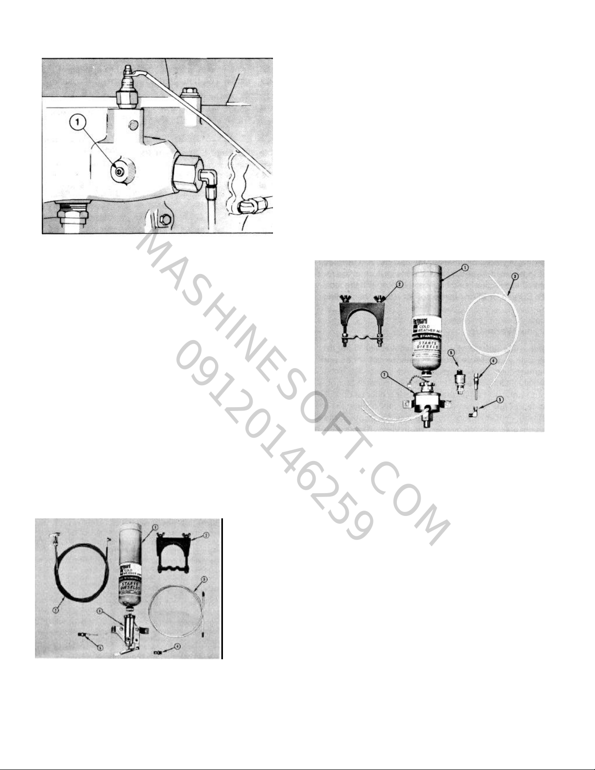
Fig 1-10 (OM1006L). Glow plug inspection hole NT-855
MASHINESOFT.COM
09120146259
C.I.D. Engine
close the glow plug manual switch for 15
seconds and observe the glow plug through the
1/8 inch plug hole. The glow plug should be
white hot; if not, connect the wiring to a 6- to 12volt (as used) source and check the amperage;
it should be 30 to 32 (minimum). If the glow
plug is all right, check the manual switch and
resistor (if used) and replace if necessary.
TM 5-2815-233-14
Manually Operated Valve
The manually operated valve, illustrated in Fig. 1-11
includes the valve body assembly (6), clamp (2) and
nylon tube (3). The fuel cylinder (1), atomizer fitting (5)
and pull control (7) must be ordered separately.
Standard pull or throttle control cables may be used, to
actuate the manual valve, if desired.
Electrically Operated Valve
The electrically operated valve, Fig. 1-12, includes the
valve body (7), 90 degree elbow (5), clamp (2), push
button switch (6), and nylon tube (3). The thermostat is
mounted on the engine exhaust manifold and cuts out
the valve by sensing manifold heat when the engine is
running. See parts catalog for fuel cylinder (1) and fuel
atomizer fittings (4). These fittings must be ordered
separately, as required.
Note: The preheater priming pump, switches and
resistor are located at the instrument panel and are to
be checked during engine starting.
The cold starting aid, approved for use in Cummins
Engines, has been based upon starting aid capabilities
to -25° F [-32° C].
Caution: Do not attempt to use vapor compound
type starting aids near heat, open flame or on
engines equipped with a glow plug system.
Fig. 1-11 (OM1007L). Manually operated valve
Fig. 1-12(OM1008L). Electrically operated valve
Installation Recommendations
The atomizer fittings must be mounted in the engine air
intake manifold or inlet connection to provide an equal
distribution of starting fuel to each cylinder. The
atomizer holes are 180 degrees apart and must be
mounted so the spray is injected the "long way" of the
manifold. If incorrectly installed, the spray goes
crosswise of the manifold.
Recommended Starting Technique Using
Fleetguard Starting Aid
1. Set the throttle for idle.
2. Disengage the driven unit or make sure gears
are in neutral.
3. Open the manual fuel shut-down valve, or
electric
1-5
Page 11

Operation and Maintenance
MASHINESOFT.COM
09120146259
Construction and Industrial
shut-down valve, whichever is used.
4. Engage the starter and while cranking, apply
metered amounts of starting fluid until the
engine idles smoothly.
Use of Starting Fluid Without Metering Equipment
1. Spray starting fluid into the air cleaner intake,
while a second man cranks the engine.
Warning: Never handle starting fluid near an open
flame. Never use it with a preheater or flame
thrower equipment. Do not breathe the fumes. Use
of too much will cause excessively high pressures
and detonation, or over speed the engine.
2. Starting aid fumes will be drawn into the air
intake manifold and the cold engine should start
without difficulty.
Waming: Fuel oil or volatile fuel cold starting aids
are not to be used in underground mine or tunnel
operations. If the engine is so equipped check with
the local U.S. Bureau of Mines Inspector for use of
the starting aid.
Note: Engines in many applications are applied at a
lower than maximum rated speed; check the serial
dataplate.
Power generator units are pre-set to operate at a
specific governed rpm.
Table 1-1: Engine Speeds (RPM)
Engine Maximum
Model Rated
All NH, NT, 855-R, 855-L 2100
All NH, NT 2300
V-903 2600
VT-903 2400
V-378, V-504, V-555 3000
V-378, V-504, V-555 3300
V-1710, V-1710-L 2100
KT-1150 2100
KTA-1150 2100
KT-2300 2100
KTA-2300 2100
KTA3067 2100
Engine Warm-Up
When the engine is started, it takes a while to get the
lubricating oil film re-established between shafts and
bearings and between pistons and liners. The most
favorable clearances between moving parts are
obtained only after all engine parts reach normal
operating temperature. Avoid seizing pistons in liners
and running dry shafts in dry bearings by bringing the
engine up to operating speed gradually as it warms up.
On some emergency equipment (such as fire pump
engines) warm-up may not be necessary due to the
equipment being housed inside a heated building. For
an engine starting with a parasitic load, such as a fire
pump, the coolant temperatures must be a mini-mum of
120°F [49°C].
Engine Speeds
All Cummins engines are equipped with governors to
prevent speeds in excess of the minimum or predetermined lower speed rating.
The governor has two functions: First, it provides the
fuel needed for idling when the throttle is in the idle
position. Second, it overrides the throttle and shuts off
the fuel if the engine rpm exceeds the maximum rated
speed.
Speeds listed in Table 1-1 are for engines rated at
maximum rpm and fuel rate.
Oil Temperature
The oil temperature gauge normally should read
between 180° F [82° C] and 225° F [107° C]. Under full
load conditions, an oil temperature of 240°F [116°C] for
a short period is not cause for alarm.
Caution: Any sudden increase in oil temperature
which is not caused by a load increase is a warning
of possible mechanical failure and should be
investigated at once.
During the warm-up period, apply the load gradually
until the oil temperature reaches 140° F [60° C]. While
the oil is cold it does not do a good job of lubricating.
Continuous operation or long periods of idle with oil
temperatures below 140 F [60C] may cause crank-case
dilution and acids in the lubricating oil which quickly
accelerate engine wear.
Water Temperature
A water temperature of 160° to 200° F [710 to 93° C] is
the best assurance that the working parts of the engine
have expanded evenly to the most favorable oil
clearances. Maximum engine coolant temperatures
should not exceed 200°F [93°C].
Keep the thermostats in the engine during summer and
winter, avoid long periods of idling, and take the
necessary steps to keep the water temperature up to a
1-6
Page 12

TM 5-2815-233-14
MASHINESOFT.COM
09120146259
Table 1-2: Oil Pressure PSI [kPa] @ 225°F [1070C]
Engine Series Minimum @ Idle Speed Rated Speed
NH/NT 8 [55] 40/70 [276/483]
Big Cam 11 8 [55] 25/45 [172/310]
VT-350, V-903, VT-903 5 [34] 40/65 [276/448]
V/VT-378, V/VT-504, VNT-555 10 [69] 50/90 [345/620]
VNT/VTA-1710 15 [103] 50/90 [345/620]
KT/KTA-1150 15 [103] 45/70 [310/483]
KT/KTA-2300 @ 2100 RPM 15 [103] 45/70 [310/483]
KT/KTA-2300 @ 1500, 1800 or 1950 RPM 15 [103] 40/70 [276/483]
KT/KTA-3067 @ 2100 RPM 20 [138] 45/70 [310/483]
KT/KTA-3067 @ 1500 or 1800 RPM 15 [103] 40/70 [276/483]
minimum of 160°F [71°C]. If necessary in cold
weather, use radiator shutters or cover a part of the
radiator to prevent overcooling.
3. Engage the power take-off.
Oil Pressure
Normal engine oil pressures at 225°F [107°C] oil
temperature are listed in Table 1-2.
Note: Individual engines may vary from the above
normal pressures. Observe and record the pressure
when the engine is new to serve as a guide for an
indication of progressive engine condition. (High oil
pressure during start-up is not cause for alarm.) For
record purposes these readings are more accurate and
reliable when taken immediately after an oil change.
High Altitude Operation
Some engines, particularly naturally aspirated, lose
horsepower when they are operated at high altitude
because the air is too thin to burn as much fuel as at sea
level. This loss is about 3 percent for each 1000 ft
[304.8 m] of altitude above sea level for a naturally
aspirated engine. Operate the engine using a lower
power requirement at high altitude to prevent smoke and
over-fueling.
Power Take-Off Application With PT (type G)
VS Fuel Pump
The VS fuel pump governor lever is used to change the
standard governed speed of the engine from rated
speed to an intermediate power take-off speed. When
changing from the standard speed range to the power
take-off speed with the engine idling on stand-ard
throttle, operate as follows:
1. Place the VS speed control lever in the
operating position.
2. Lock the standard throttle in the full-open
position.
To return to standard throttle:
1. Disengage the power take-off.
2. Return the standard throttle to the idle position.
3. Lock the VS speed control lever in the
maximum speed position.
Engine Shut-Down
Idle Engine A Few Minutes Before Shut-Down
It is important to idle an engine 3 to 5 minutes before
shutting it down to allow the lubricating oil and water to
carry heat away from the combustion chamber,
bearings, shafts, etc. This is especially important with
turbocharged engines.
The turbocharger contains bearings and seals that are
subject to the high heat of combustion exhaust gases.
While the engine is running, this heat is carried away by
oil circulation, but if the engine is stopped sudden-ly, the
turbocharger temperature may rise as much as 100° F
[380 C]. The results of the extreme heat may be seized
bearings or loose oil seals.
Do Not Idle Engine for Excessively Long Periods
Long periods of idling are not good for an engine
because the combustion chamber temperatures drop so
low the fuel may not burn completely. This will cause
carbon to clog the injector spray holes and piston rings
and may result in stuck valves.
If the engine coolant temperature becomes too low,
1-7
Page 13
raw fuel will wash the lubricating oil off the cylinder walls
MASHINESOFT.COM
09120146259
and dilute the crankcase oil so all moving parts of the
engine will suffer from poor lubrication. If the engine is
not being used, shut it down.
Turn Switch to "Off" Position to Shut Down the
Engine
The engine can be shut down completely by turning off
the switch on installations equipped with an electric
shut-down valve, or by turning the manual shut-down
valve knob. Turning off the switch which controls the
electric shut-down valve stops the engine unless the
override button on the shut-down valve has been locked
in the open position. If the manual override on the
electric shut-down valve is being used, turn the button
fully counterclockwise to stop the engine. Refer to
"Normal Starting Procedure". The valve cannot be
reopened by the switch until after the engine comes to a
complete stop, unless a rapid re-start valve is installed.
Caution: Never leave the switch key or the override
button in the valve open or in the run position when
the engine is not running. With overhead tanks this
would allow fuel to drain into the cylinders, causing
a hydraulic lock.
Operation and Maintenance
Construction and Industrial
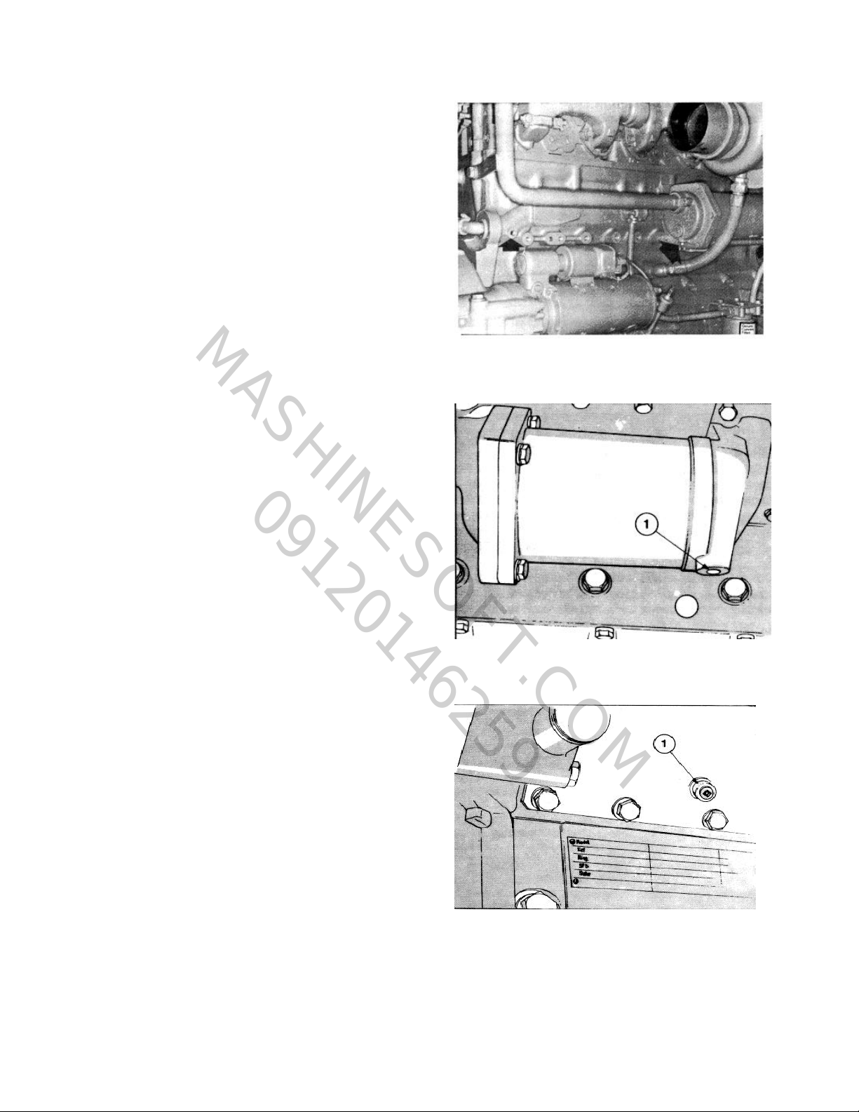
Fig. 1-13 (OM1010L). Cooling system drain points-NT-
855 C.I.D. Engine
Stop Engine Immediately If Any Parts Fail
Practically all failures give some warning to the operator
before the parts fail and ruin the engine. Many engines
are saved because alert operators heed warning signs
(sudden drop in oil pressure, unusual noises, etc.) and
immediately shut down the engine.
Cold-Weather Protection
1. For cold-weather operation, use of permanenttype antifreeze with rust inhibitor additives is
recommended. See Section 3.
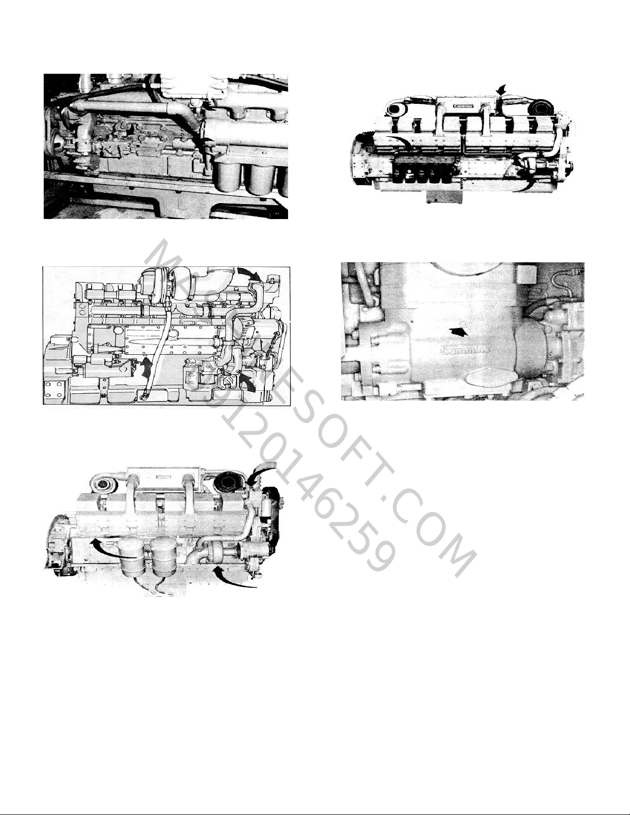
2. Drain the cylinder block and heads on all
engines by opening the petcocks and removing
the drain plugs as shown in Fig's. 1-13 to 1-19.
3. Immersion-type water and oil heaters are
If an air compressor (Fig. 1-20), heat exchanger
or other "water cooled" accessory is used, open
the petcock and drain. Failure to properly drain
the engine and accessories may cause serious
damage during freezing weather.
available for engines used in cold-weather
operations and to maintain temperatures to
permit the engine to operate at full load at startup.
Fig. 1-14 (OM1012L). Cooling system drain points (oil
cooler side) VT-903 C.I.D. Engine
Fig. 1-15 (OM1013L). Cooling system drain points (left
bank side) VN/VT-555 C.I.D. Engine
1-8
Page 14
TM 5-2815-233-14
MASHINESOFT.COM
09120146259
Fig. 1-16, (V40033). Coolant drain point - V/VT-1710
Engine
Fig 1-17,(OM1009L). Cooling system drain points-
KT/KTA-1150 C.I.D. Engine
Fig. 1-18, (K21903). Coolant drain point - KT(A)-2300
Engine
Fig. 1-19, (OM203.). Coolant drain point - KTA-3067
Engine
Fig. 1-20, (K21904). Two cylinder air compressor
coolant drain
Engine Operation in Cold Weather
Satisfactory performance of a diesel engine operating in
low ambient temperature conditions requires
modification of the engine, surrounding equipment,
operating practices and maintenance procedures. The
colder the temperatures encountered the greater the
amount of modification required and yet with the
modifications applied, the engines must still be capable
of operation in warmer climates without extensive
changes. The following information is provided to
engine owners, operators and maintenance personnel
on how the modifications can be applied to get
satisfactory performance from their diesel engines.
There are three basic objectives to be accomplished:
1. Reasonable starting characteristics followed by
1-9
Page 15

Operation and Maintenance
MASHINESOFT.COM
09120146259
Construction and Industrial
practical and dependable warm-up of the engine and
equipment.
2. A unit or installation which is as independent as
possible from external influences.
3. Modifications which maintain satisfactory operating
temperatures with a minimum increase in maintenance
of the equipment and accessories.
If satisfactory engine temperature is not maintained,
higher maintenance cost will result due to the increased
engine wear, poor performance and formation of
excessive carbon, varnish and other deposits. Special
provisions to overcome low temperatures are definitely
necessary, Whereas a change to warmer climate
normally requires only a minimum of revision. Most of
the accessories should be designed in such a way that
they can be disconnected so there is little effect on the
engine when they are not in use.
The two most commonly used terms associated with
preparation of equipment for low temperature operation
are "Winterization" and "Arctic Specifications"
Winterization of the engine and/or components so
starting and operation are possible in the lowest
temperature to 'be encountered requires:
1. Use of correct materials.
3. Protection from the low temperature air. The metal
temperature does not change, but the rate of heat
dissipation is affected.
4. Fuel of the proper grade for the lowest temperature.
5. Heating to be provided to increase the engine block
and component temperature to a minimum of -25° F
[-32° C] for starting in lower temperatures.
6. Proper external heating source available.
7. Electrical equipment capable of operating in the
lowest expected temperature.
Arctic specifications refer to the design material and
specifications of the components necessary for
satisfactory engine operation in extreme low
temperatures to -65° F [-54° C]. Contact Cummins
Engine Company, Inc., or the equipment manufacturer
to obtain the special items required.
Caution: "Anti-leak" antifreezes are not
recommended for use in Cummins Engines.
Although these antifreezes are chemically
compatible with DCA water treatment, the "antileak" agents may clog the coolant filters and render
them ineffective.
2. Proper lubrication, 'low temperature lubricating oils.
1-10
Page 16

Industrial Fire Pump Engines
MASHINESOFT.COM
09120146259
Fire pump engines are built and applied under
conditions set down by agencies such as Underwriters
Laboratory; therefore, parts originally supplied must not
be deviated from without qualifying agency approval.
The following instructions are those special items
necessary to this application, and should be used in
conjunction with those previously stated.
Maintenance Instructions
10. Check the crankcase oil level and fill it to the high
mark.
11. Start the engine and adjust overspeed.
12. Remove ST-1224 and replace the original adapter.
Initial Start-Up Note: Contact operating personnel
responsible for fire protection system before starting.
Obtain approval to service or repair. After repair obtain
authorized signature of acceptance.
1. Remove the heat exchanger cap, check or fill the
engine coolant supply; open the water filter inlet and
outlet valves.
2. Prelubricate the engine with oil meeting
specifications MIL-L-46152 (API-CC/SC) viscosity
10W30. This includes removal of the turbocharger
oil inlet line on turbocharged engines to prelubricate
the housing by adding 2 to 3 oz [60 cc] of clean
engine lubricating oil.
3. Check the crankcase oil level and fill to the high
mark on the dipstick.
4. Remove the fuel pump solenoid lead and crank the
engine through both cranking cycles.
5. If the engine is equipped with a "Vernier throttle",
place it in the idle position; if not, place the MVS
throttle in the idle position. On turbocharged models
the delay cylinder line may be disconnected at the
block and the block opening plugged.
6. Reconnect the fuel solenoid lead and start the
engine; run it at idle speed.
7. Verify the lubricating oil pressure has been
established, normally in 6 to 8 seconds.
Note: Some automatic controllers require lubricating oil
pressure higher than the normal pressure at 600 rpm
idle. Increase the idle to 800 to 900 rpm if this condition
is encountered. All turbocharged engines should be set
to 800 to 900 rpm idle.
13. Clean the raw water strainer.
14. Start the engine and adjust operating speed.
15. Adjust the raw water pressure regulator.
16. Engine is now ready for normal operation.
Normal Operation
1. Daily or normal operation would include the
checking of fuel, lubrication oil, coolant and
correcting any leaks or unusual conditions as
required.
2. Check the coolant and oil heaters to assure at least
120° F [49° C] water temperature has been
maintained.
3. Manually start the engine using the prescribed
starting procedure.
4. Operate the engine the prescribed period of time or
5 minutes after stabilization of the coolant
temperature.
5. Shut the engine down using the normal test
shutdown procedures.
Fire Pump Engines -Overspeed
Switch Adjustment
(IF Engine Models)
The speed switches required for overspeed protection
on fire pump engines require high speed for the
overspeed adjustment. All engines are now being
shipped adjusted at the maximum overspeed. The
following overspeed adjustments are 20 percent above
the rated engine speed.
8. Continue to operate the engine for 3 to 5 minutes
and review all systems for leaks or unusual
conditions; correct as required.
9. Stop the engine and install ST-1224 Adapter.
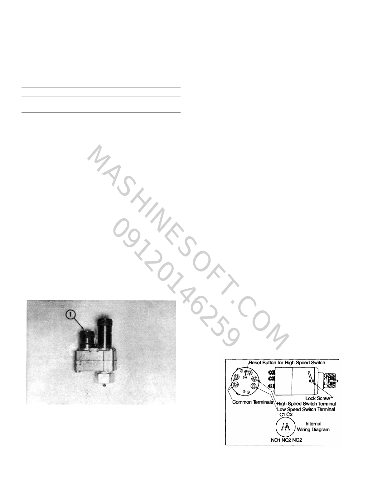
An adapter, ST-1224 with 2:1 ratio, in speed switch
drive only, (1, Fig. 1-21) is available to drive the speed
switch at twice the engine speed. This tool when
1-11
Page 17
Operation and Maintenance
MASHINESOFT.COM
09120146259
Construction and Industrial
installed in place of the existing adapter permits
adjustment to be made to the speed switch at slightly
over 1/2 engine and pump speed. This maintains a
pump speed well within its safe speed range while the
adjustments are being made.
Table 1-3: Engine Overspeeds
Engine Rated
Model Speed Overspeed
V-378F1 1750-2200 2100-2640
V-378F2 2400-3300 2880-3960
V-504-F1 1750-2200 2100-2640
V-504-F2 2400-3300 2880-3960
N-855 1460-2100 1750-2520
NT-855-F1 1750-2100 2100-2520
NT-855-F2 1750-2300 2100-2760
VT-1710-F 1750-2100 2100-2520
Adjustment Procedure
1. Remove the present tachometer drive adapter.
2. Install the service tool, ST-1224, in position of the
standard drive adapter. Connect the tachometer
and overspeed stop switch to the ST-1224 Tool.
a. On inline engine models, this. can be
accomplished by adjusting the Vernier throttle
control.
b. On Medium Duty V engines, the speed
adjustment must be made by adjusting the
governor idle and maximum speed screws. The
idle screw is housed in the front of the MVS
governor. The maximum speed screw is
mounted to the MVS governor by a bracket and
is on the left hand side of the fuel pump.
Engine slow down is accomplished by turning
the idle speed screw counterclockwise and'
turning the maximum speed screw in a
clockwise direction. To increase the engine
speed reverse the procedure.
5. Set the single element speed switch.
a. Remove the lockwire from setscrews on the side
of the switch. Loosen the three (3) setscrews.
b. Rotate the cover clockwise (this decreases trip
speed) until the switch actuates and stops the
engine.
Note: The overspeed stop switch cable must be
connected to the short adapter connection. (1, Fig. 1-
21).
3. Start the engine and warm to operating temperature.
4. Set the engine speed to one-half (1/2) the desired
engine shut-down speed as indicated by the
tachometer.
c. Secure the setscrews and replace the locking
wire.
d. On manual reset models, re-activate the switch
by pushing the reset button on top of the switch.
6. Set the dual element speed switches.
Caution: Do not break or remove the lockwire.
a. Remove the round head dust cover screw
marked 2 from the top of the switch. Fig. 1-22.
b. Insert a 1/16 inch Hex Allen wrench into the
adjusting screw located just below the surface of
the cover.
Fig. 1-21, (ST-1224). ST-1224 adapter
Fig. 1-22, (CGS27). Double speed switch
1-12
Page 18
c. Turn counterclockwise to lower the engine shut-
MASHINESOFT.COM
09120146259
down speed. Turn clockwise to raise the engine
shut-down speed.
Caution: Do not turn the adjusting screw more than
three (3) revolutions in either direction from the
factory setting. Do not attempt to set the duel
element switch in the same manner as the single
element switch.
d. Replace the dust cover screw removed in "Step
a" above.
TM 5-2815-233-14
e. All overspeed switches must be manually reset,
reactivate the switch by pushing the reset button
on top of the switch.
7. Replace the service tool, ST-1224, with the original
drive adapter and reconnect the cables.
Note: If the stop crank adjustment is required do not
use the ST-1224 Adapter. Replace with a standard
adapter to effect the adjustment.
Fire Pump Engine Operating Speed Adjustment
All Cummins fire pump engines will be shipped adjusted
at the speeds in Table 1-4, unless prior approval has
been established for a specific speed.
Final operating speed adjustment should be made at the
time of the in-service inspection to obtain the required
fire pump operating speed.
This speed adjustment must be made with the Vernier
throttle in the full fuel position and the systems fire
pump operating at its rated condition. All speed ranges
of N-NT and V-12 models are available by adjusting the
VS high speed adjusting screw. Fig's. 1-23 and 1-24.
Table 1-4: Fire Pump Engine Operating Speed
Fuel Factory Maximum
Engine Pump Adjusted Operating
Model Code Speed Speed
V-378-F1 C-653 1750 2200
V-378-F2 C-651 2400 3300
V-504 F1 C-652 1750 2200
V-504 F2 C-650 2400 3300
N-855 8761 1750 2100
NT-855 Fl 8770 1750 2100
NT-855 F2 8771 1750 2300
VT-1710 F 8784 1750 2100
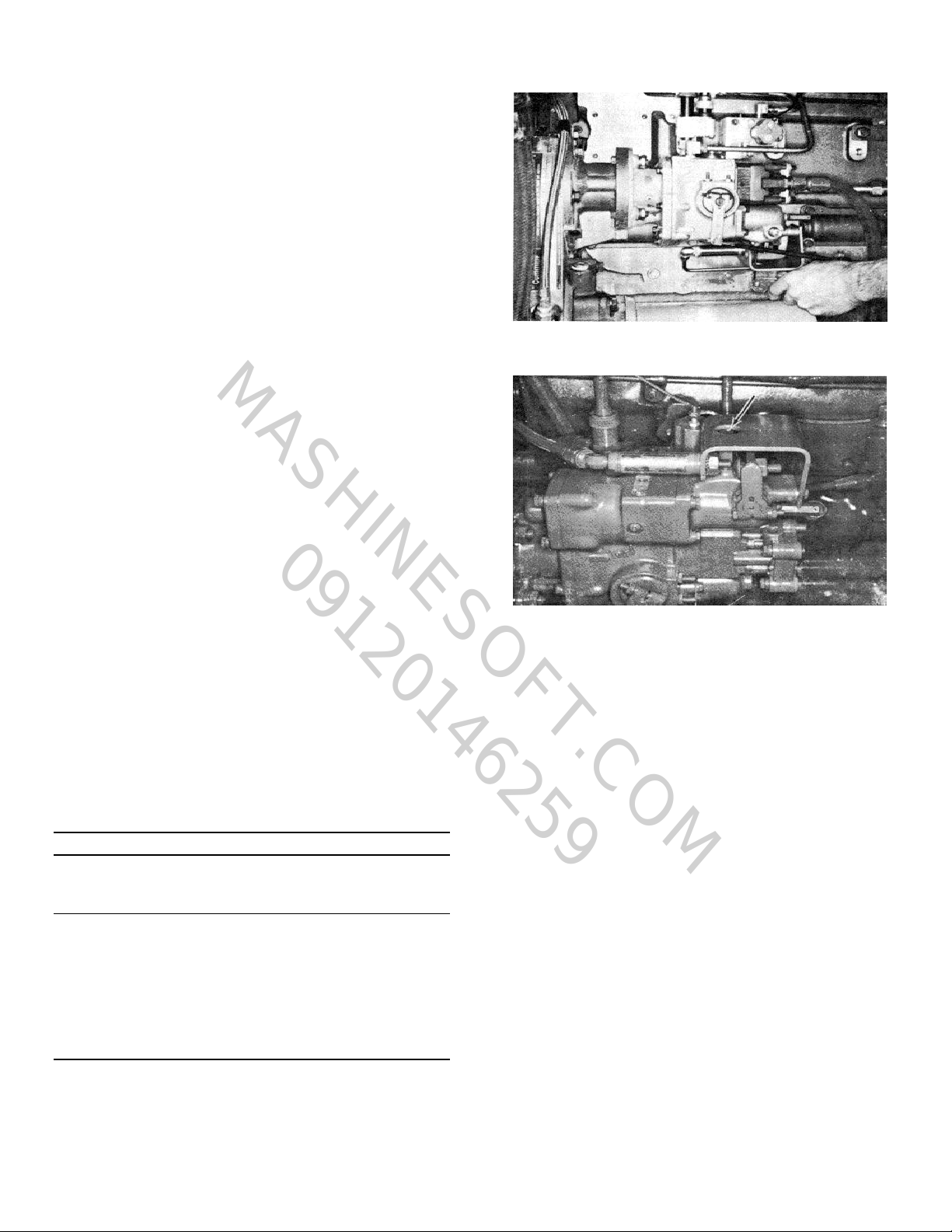
Fig. 1-23, (N11979). Adjusting engine speed
Fig. 1-24, (N11980). Governor adjusting screw
ment is made by loosening the 7/16 inch locking nut and
backing the screw out to increase the engine speed
through the full speed range.
The V-378 and V-504 F1 and F2 models require two
differently calibrated fuel pumps. One pump code
provides speeds between 1750 and 2300 rpm. A
different pump code is required for speeds between
2400 and 3300 rpm. The required speeds on these
models are similarly obtained by MVS adjustment within
the calibrated range as indicated above. It normally is
prohibited by UL and FM to change engine ratings by
changing fuel pumps on any models of fire pump
engines. In the event of fuel pump rebuild, the pump
must be calibrated to the original code and any
deviation would be a violation to the insurance
agencies approval.
This screw requires a 1/8 inch Allen wrench and adjust-
1-13
Page 19
MASHINESOFT.COM
09120146259
1-14
Page 20

Maintenance Instructions
MASHINESOFT.COM
09120146259
Maintenance is the key to lower operating costs. A
Maintenance diesel engine requires regularly scheduled maintenance
to keep it running efficiently.
Maintenance Schedule
Preventive maintenance is the easiest and least
expensive type of maintenance. It permits the
Maintenance Department to do the work at a convenient
time.
A Good Maintenance Schedule Depends On Engine
Application
Actual operating environment of the engine governs the
maintenance schedule. The suggested check sheet on
the following page indicates some checks have to be
performed more often under heavy dust or other special
conditions.
Using the Suggested Schedule Check Sheet
The maintenance schedule check sheet is designed as a
guide until adequate experience is obtained to establish
a schedule to meet a specific operation.
A detailed list of component checks is provided through
several check periods; also a suggested schedule basis
is given for hours of operation, or calendar of time.
A maintenance schedule should be established using
the check sheet as a guide; the result will be a
maintenance program to fit a specific operation.
The check sheet shown can be reproduced by any
printer. The person making each check can then
indicate directly on the sheet that the operation has
been completed. When a complete column (Under A,
B, C, etc.) of checks is indicated, the engine will be
ready for additional service until the next check is due.
Storage for Engines Out of Service
If an engine-remains out of service and its use is not
immediately forthcoming, special precautions should be
taken to prevent rust. Contact the nearest Cummins
Distributor or consult applicable Shop Manual for
information concerning engine storage procedure.
2-1
Page 21

MASHINESOFT.COM
09120146259
2-2
Page 22
MASHINESOFT.COM
09120146259
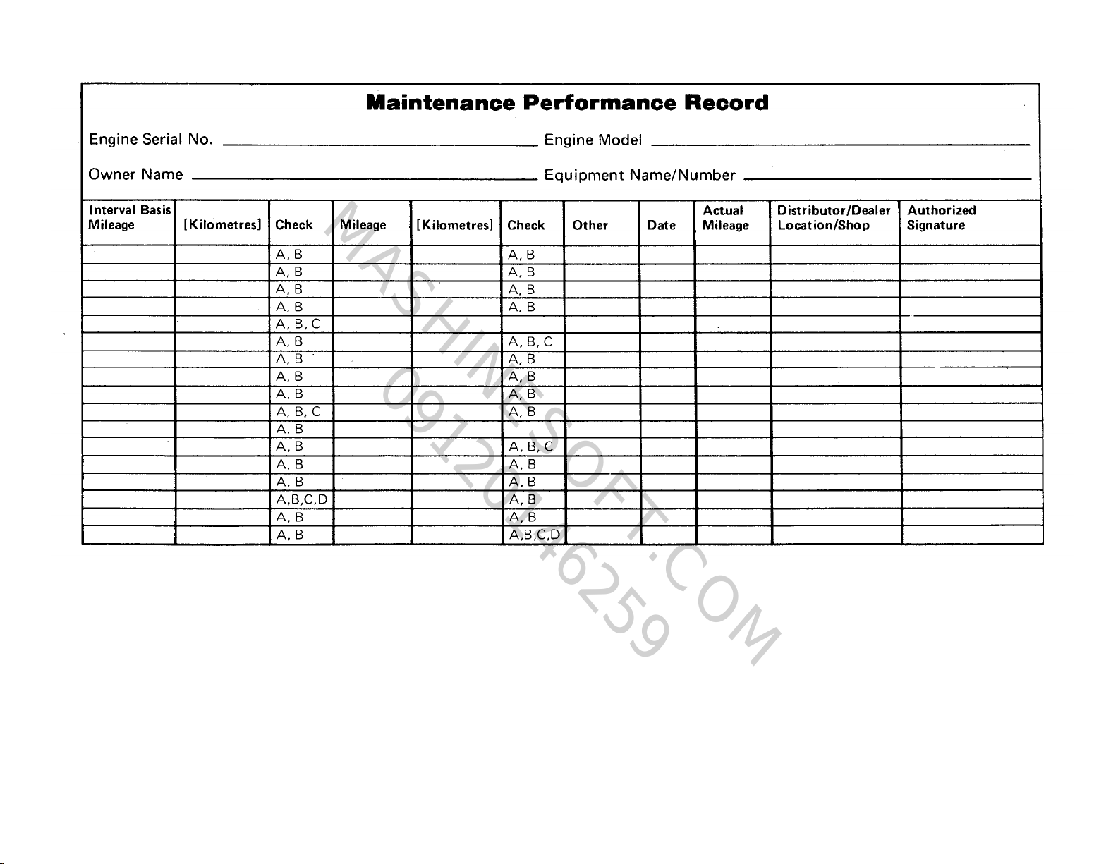
To prove that the Engine has been properly maintained retain records, such as work orders and receipts, showing that scheduled maintenance has
been performed. The maintenance record form on this page is for that purpose.
2-3
Page 23

Operation and Maintenance
MASHINESOFT.COM
09120146259
Construction and Industrial
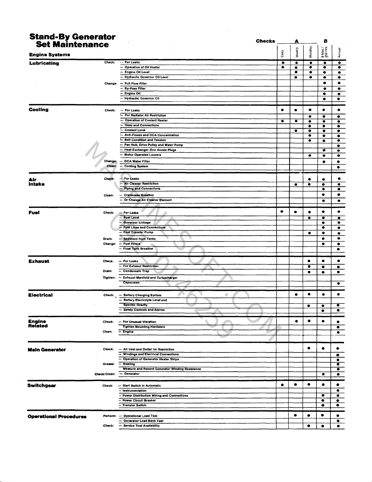
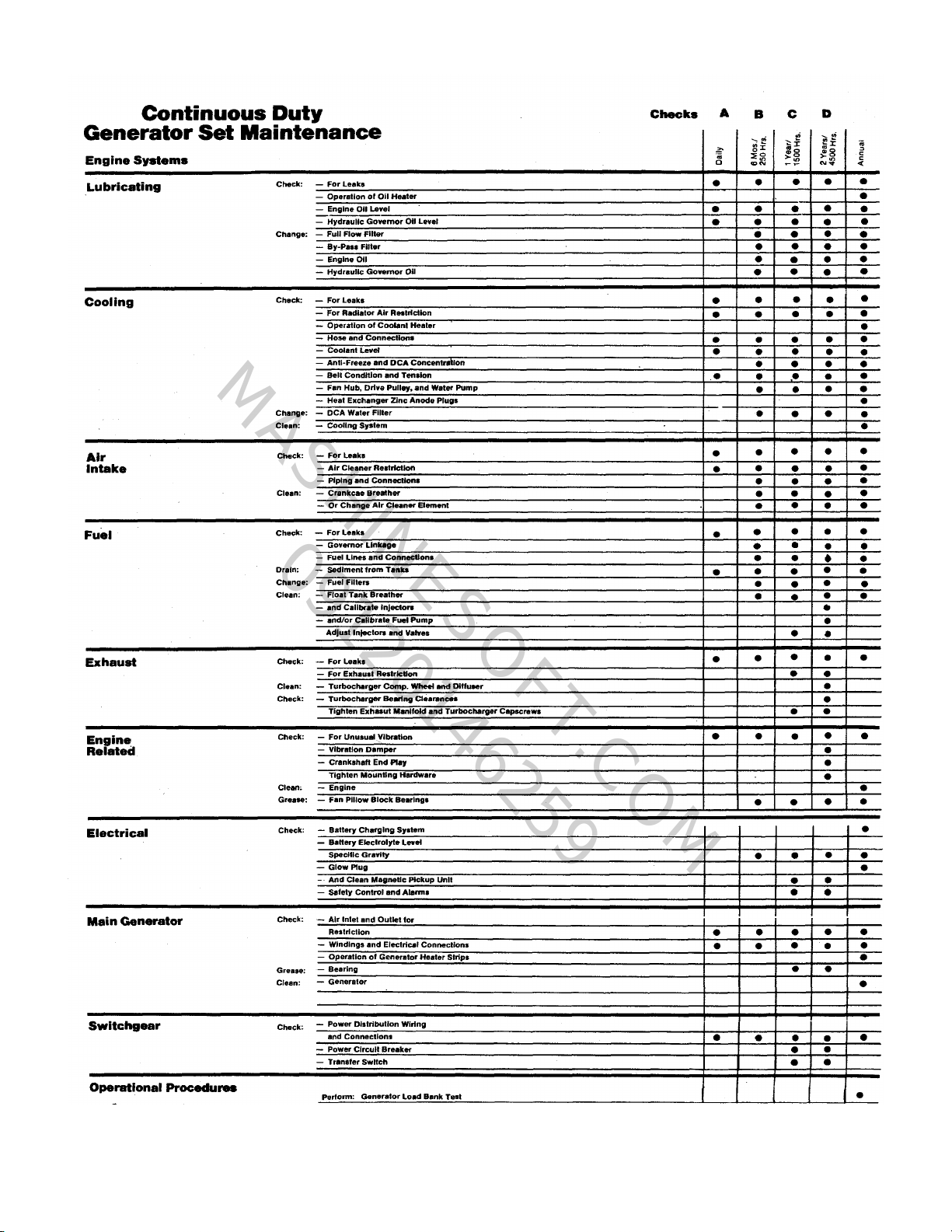
Scheduled Maintenance
Schedule I, Schedule II
The following maintenance schedules should be used to
establish maintenance practices for Cummins standby
(GS) or continuous duty (GC) generator sets.
Schedule I is used with standby applications. Many of
these installations are regulated by NFPA and/or local
codes (reference NFPA No. 76A).
Standby rated generator sets are for supplying electric
power in the event of normal utility power failure. No
overload capability is available for this rating. This
rating may be used for continuous service for as long as
the emergency may last. This rating conforms with the
BS 649:1958 overload rating and DIN "B" 6270.
Schedule II is used with continuous duty applications.
Continuous duty rated generator sets are for supplying
electric power in lieu of commercially purchased power.
Intermittent overloads up to the standby rating are
allowable. This rating may be used for continuous
service in commercial applications and it conforms with
BS 649:1958 and DIN "A" 6270 for generator set
applications.
Using The Suggested Schedule Check Sheet
Actual operating environment of the engine governs the
maintenance schedule. The-suggested check sheet on
the following page indicates some checks have to be
performed more often under heavy dust or other special
conditions.
The maintenance schedule check sheet is designed as a
guide until adequate experience is obtained to establish
a schedule to meet a specific operation.
A detailed list of component checks is provided through
several check periods; also a suggested schedule basis
is given for hours of operation, or calendar of time.
A maintenance schedule should be established using
the check sheet as a guide; the result will be a
maintenance program to fit a specific operation.
Cummins Standby Generator Sets
Cummins standby generator sets may be required to
start and come on line in 10 seconds or less.
These engines must be equipped with engine coolant
heaters capable of maintaining coolant temperature at a
minimum of 100°F [38° C].
Engines subject to ambient temperatures less than 2-4
70° F [21° C] must also be equipped with a lubricating
oil heater. When using a lubricating oil heater
immersed in oil, the maximum surface of heater in
contact with oil, should be less than 300° F [149° C] to
minimize formation of hard carbon on the heating
element.
Recommended wattage for the heaters when the unit is
in a protected area or in an enclosure are shown in
Bulletin No. 3379009, in Section 7 Miscellaneous.
Standby units should be operated once a week under a
minimum of 25% of rated KW load for at least thirty
minutes. During this test, the engine must reach normal
operating temperature.
Cummins Continuous Duty Generator Sets
Continuous duty generator sets may be equipped with a
cold starting aid. Maintenance procedures for these
devices can be found in the seasonal maintenance
section.
2-4
Page 24
MASHINESOFT.COM
09120146259
2-5
Page 25
MASHINESOFT.COM
09120146259
2-6
Page 26
"A" Maintenance Checks-Daily
MASHINESOFT.COM
09120146259
Make a Daily Report of Engine Operation to the
Maintenance Department
The engine must be maintained in top mechanical
condition if the operator is to get optimum satisfaction
from its use. The maintenance department needs daily
running reports from the operator to make necessary
adjustments in the time allotted and to make provisions
for more extensive maintenance work as the reports
indicate the necessity.
Comparison and intelligent interpretation of the daily
report along with a practical follow-up action will
eliminate most failures and emergency repairs.
Maintenance Instructions
Fig. 2-1, (K21901). Checking engine oil level
Report to the Maintenance Department any of the
following conditions:
1. Low lubricating oil pressure.
2. Low power.
3. Abnormal water or oil temperature.
4. Unusual engine noise.
5. Excessive smoke.
6. Excessive use of coolant, fuel or lubricating oil.
7. Any fuel, coolant or lubricating oil leaks.
Check Engine
Check Engine Oil Level
Check Engine Coolant Level
Keep the cooling system filled to the operating level.
Check the coolant level daily or at each fuel fill point.
Investigate for causes of coolant loss. Check the
coolant level only when the system is cool.
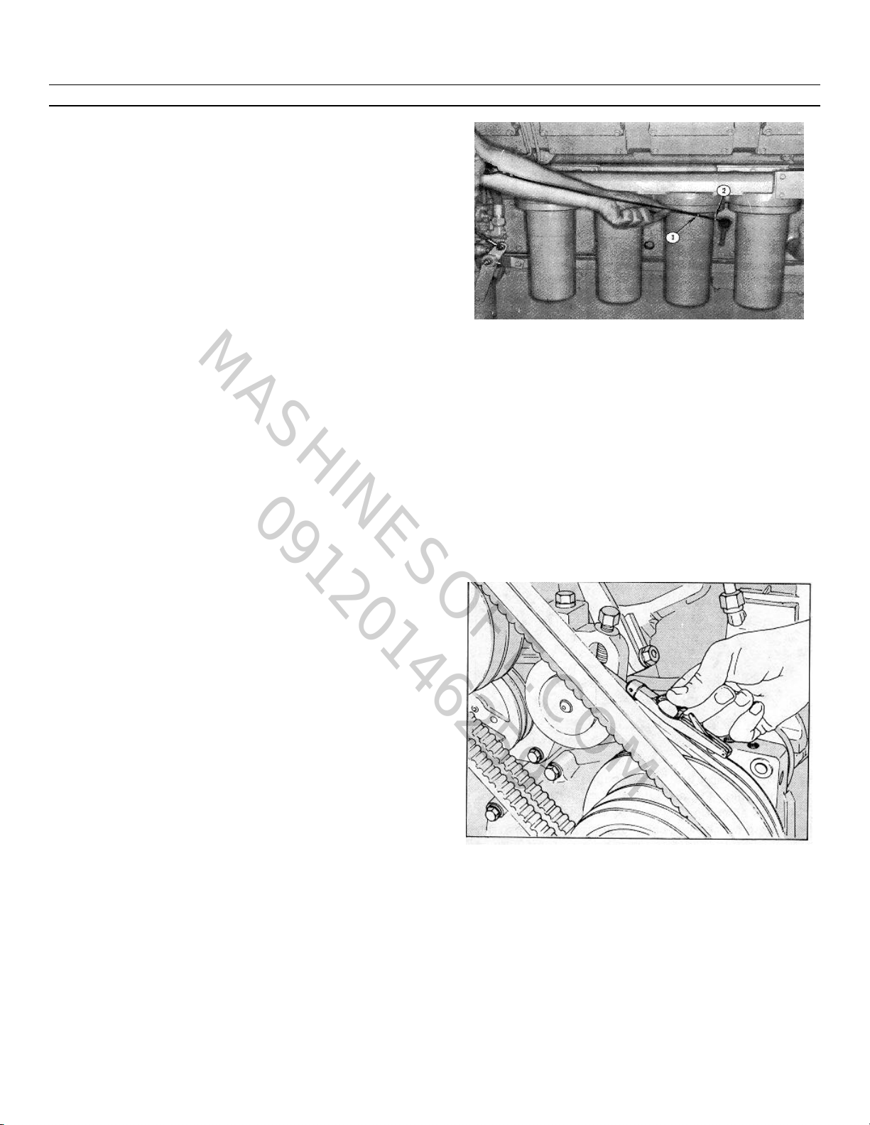
Check Belts
Visually check belts for looseness. If there is evidence
of belt slippage adjust as follows: Using the appropriate
gauge, Fig's. 2-2 and 2-3, check.
Note: Some dipsticks have dual markings, with high
and low-level marks: static oil marks on one side,
engine running at low idle speed marks on opposite
side. Be sure to use the proper scale.
1. Check the oil level with the dipstick oil gauge
located on the engine. Fig. 2-1. For accurate readings,
the oil level should not be checked for approximately 15
minutes after the engine is shut-down.
Keep the dipstick with the oil pan with which it was
originally shipped. Keep the oil level as near the "H"
(high) mark as possible.
Caution: Never operate the engine with the oil level
below the "L" (low) mark or above the "H" (high) mark.
2. If necessary, add oil of the same quality and brand
as already in the engine. See Section 3.
Fig. 2-2, (OM1014L). Checking belt tension with a Krikit
gauge
2-7
Page 27
Operation and Maintenance
MASHINESOFT.COM
09120146259
Construction and Industrial
Table 2-1: Belt Tension (Lbs.)
Belt New Belt* Minimum • Used Belt Installation Tension
Width Belt Tension Tension • If Below Min. Tension, Retention to
Inches Gauge (lb.) + 10 (lb.) (lb.) + 10
.380 ST-12748 140-150 60 100
.440 CAN-292 140-150 60 100
1/2 140-150 60 100
11/16 160-170 60 100
3/4 ST-1138 160-170 60 100
7/8 160-170 60 100
K-Sect.
5 Rib ST-1293 125-135 60 100
V-Ribbed
K-Sect
6, Rib- ST-1293 150-160 70 120
V-Ribbed
K;Sect
10 Rib NUA 250-260 140 200
V-Ribbed
* Used belts should be retensioned to values listed in this column.
Note: A belt is considered as used. if it has been in operation for a period of time of at least 5 minutes.
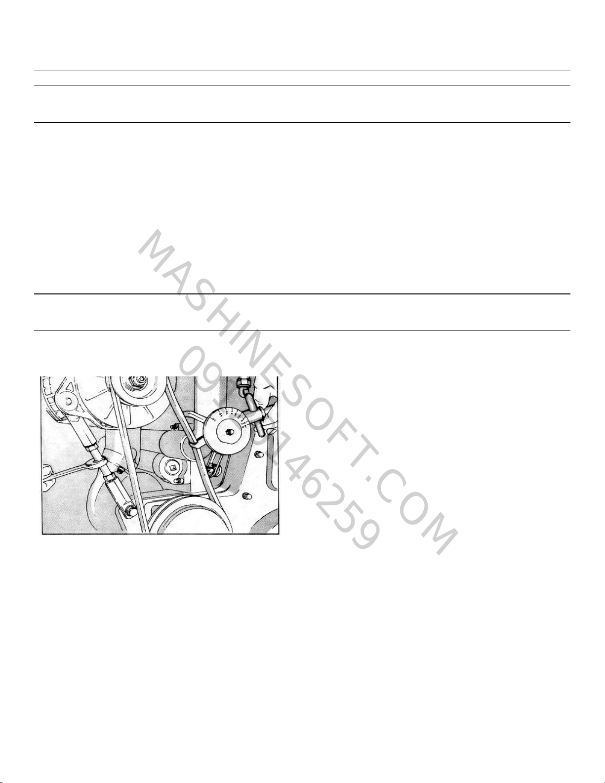
and/or adjust belts to the tension as indicated in Table 2-
1.
Inline Engine Water Pump Belts (No Idler)
1. Eccentric water pump adjustment.
a. Loosen the water pump clamp ring to allow the
pump body to turn.
b. Loosen the pump body by pulling up on the
belts. A sharp jerk may be required.
c. Insert a bar in the water pump body slots and
rotate the pump body counterclockwise to
tighten the belts.
Note: Do not adjust to final tension at this time.
Fig. 2-3, (OM1015L). Adjusting belt tension with ST-
1293
Note: When using the "Krikit" gauge the correct belt
tension reading for the belt tested must be read at the
point where the top of the black indicator arm crosses
the bottom numbered scale. Position the gauge in the
center of the belt between two pulleys. The flange at
the side of the gauge should be flat against the edge of
the belt.
d. Snug the clamp ring capscrew farthest from the
belts, on the exhaust side to 5 ft-lbs [7 N m].
e. Snug the two capscrews above and below the
first one to 5 ft-lbs [7 N m].
f. Finish tightening by alternating from side to side
in 5 ft-lbs [7 N.m] increments to a final torque of
12 to 15 ft-lbs [16 to 20 N m].
2-8
Page 28
Maintenance Instructions
MASHINESOFT.COM
09120146259
g. Check the belt tension.
Final belt tension was not obtained by adjustment alone.
The water pump body was pulled straight by snugging
the capscrews in the order described, thus increasing
the belt tension to the final value.
2. Adjustable (split) pulley water pumps, V-903
Engines only.
a. Remove the capscrews joining the sheave(s) of
the pulley.
Note: Clean the capscrew threads and holes in the
sheaves thoroughly to avoid capscrew breakage during
reassembly.
b. The outer half of the pulley is screwed onto the
hub extension of the inner half. Some pulleys
are provided with flats, and some with lugs for
barring.
c. Bar the engine over to roll the belt outward on
the pulley as the outer half is turned in.
d. Adjust the belt(s) to the tension indicated in
Table 2-1.
e. Turn the outer sheave(s) in enough to align the
capscrew holes.
f. Start the capscrews and tighten alternately and
evenly. Final tension is: 5/16-18 capscrew, 10
to 12 ft-lbs [14 to 16 N•m] 3/8-16 capscrew, 17
to 19 ft-lbs [23 to 26 N om] g. Bar the engine
over one or two revolutions to seat the belt.
h. Recheck the belt tension.
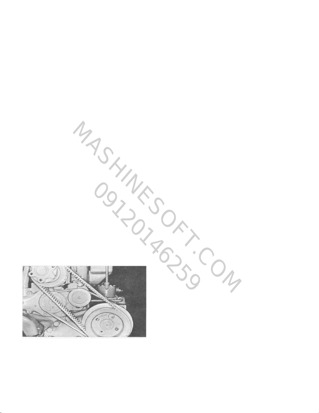
Inline Engine Water Pump Belts (With Idler)
1. Loosen the capscrews and lockwashers or locknut
securing the idler pulley to the bracket or water
pump. Fig. 2-4.
2. Using a pry bar (NTA) or adjusting screw (FFC)
adjust the idler pulley until the proper belt tension is
indicated on the gauge. See Table 2-1.
3. Secure the idler pulley or bracket in position by
tightening the locknut or capscrews and lockwashers
to 45 to 55 ft-lbs [61 to 75 N m] torque.
Note: The self tensioning idler on V-1710 belt driven
water pumps requires no adjustment or belt tension
check.
Fan Drive Belts
1. Loosen the large locking nut on the fan hub shaft or
the capscrews securing the fan hub shaft to the
mounting bracket. The fan hub will fall out of line
when this is done.
2. Turn the adjusting screw to increase the belt
tension.
3. Tighten the locknut or capscrews until the fan hub is
straight. Snug the nut to maintain the hub in proper
alignment with the fan hub bracket.
Caution: Do not adjust to full tension with the
adjusting screw, as this would result in
overtightening.
4. Belt tension should read as indicated in Table 2-1 on
applicable gauge.
5. Tighten NH/NT Engines locknut to 400 to 450 ft-lbs
[542 to 610 N m]; then back off 1/2 turn. Tighten
the four 1/2 inch capscrews, Fig. 2-5, on NTC-350
FFC Engines to 75 to 85 ft-lbs [101 to 115 N.m].
On V-903 Engines tighten capscrews to 75 ft-lbs [102
Fig. 2-4, (N11974). Water pump with idler
N.m] or single nut to 450 ft-lbs [610 N.m].
6. Recheck the belt tension.
7. Back out the adjusting screw one-half turn to
Note: The self tensioning backside idler on KT/KTA2300
and KTA-3067 belt driven fan requires no belt tension
check.
Generator/Alternator Belts
Belt tension should be as indicated in Table 2-1 when
measured with the applicable gauge.
2-9
prevent breakage.
Page 29
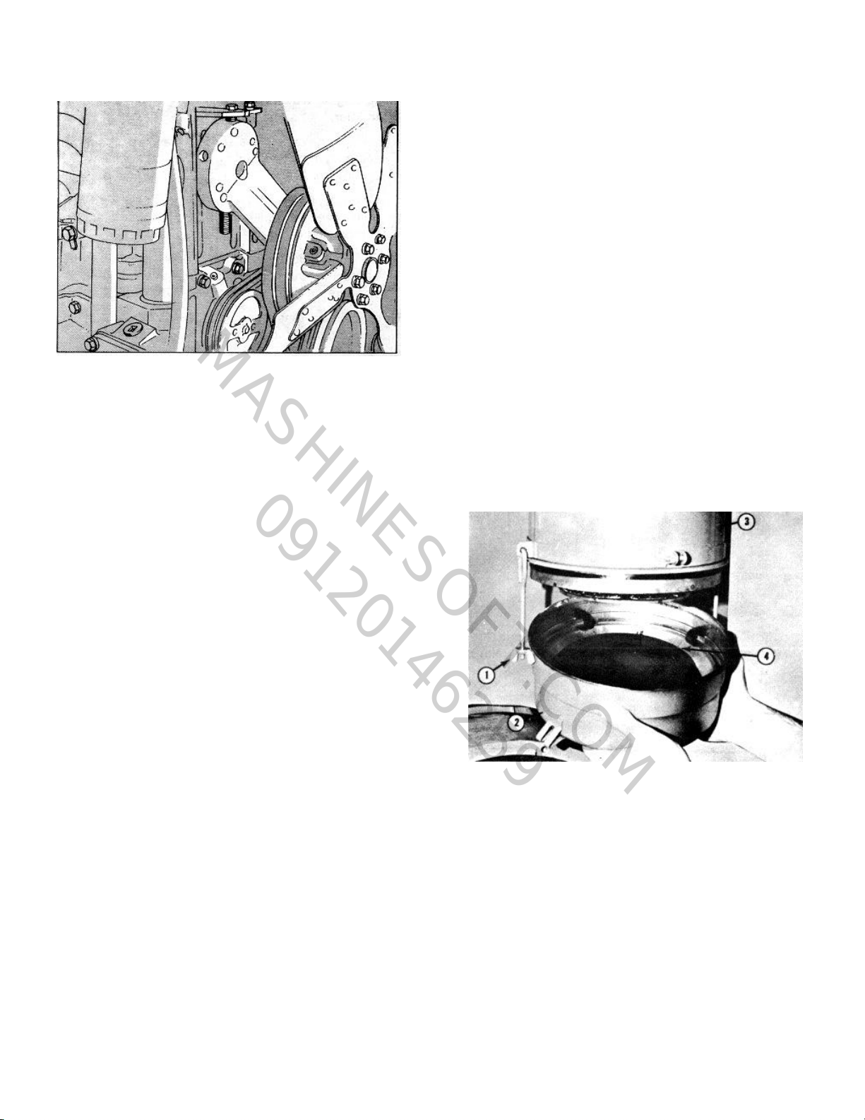
Fig. 2-5, (OM10161). Fan hub installation, NT-350 FFC
MASHINESOFT.COM
09120146259
Operation and Maintenance
Construction and Industrial
5. Do not allow belts to rub any adjacent parts 6.
Adjust belts to the proper tension.
Readjusting New Belts.
All new belts will loosen after running for 5 minutes and
must be readjusted to "belt tension after run-in" Ref.
Table 2-1.
Check Oil Bath Cleaner Oil Level.
Daily check oil level, Fig. 2-6, in the oil bath air cleaner
to be sure the oil level in the cup is at the indicated
mark. Refill as required.
*Cummins Engine Company, Inc. recommends the use
of dry type air cleaners.
Belt Installation.
If the belts show wear or fraying, replace as follows:
1. Always shorten the distance between the pulley
centers so the belt can be installed without force.
Never roll a belt over the pulley and never pry it on with
a tool such as a screwdriver. Either of these methods
will damage the belts and cause early failure.
2. Always replace the belts in complete sets. Belts
riding depth should not vary over 1/16 in [1.6 mm]
on matched belt sets.
3. Pulley misalignment must not exceed 1/16 in 11.
4. Belts should not bottom on the pulley grooves nor
6 mm] for each ft 10.3 m] of distance between
the pulley centers.
should they protrude over 3/32 in [2.4 mm] above
the top edge of the groove.
Check for Damage.
Visually check the fuel system, etc., for misadjustment
or tampering; check all connections for leaks or
damage. Check the engine for damage; correct as
necessary.
Fig. 2-6, (Nl1001). Checking oil level in air cleaner
2-10
Page 30
Maintenance Instructions
MASHINESOFT.COM
09120146259
"A" Maintenance Checks-Weekly
Repeat Daily Checks
Check Air Cleaner
Clean Pre-Cleaner and Dust Pan
Under extremely dirty conditions an air pre-cleaner may
be used. Clean the pre-cleaner jar and dry-type air
cleaner dust pans daily or more often, as necessary,
depending on operating conditions.
Check Inlet Air Restriction
Mechanical Indicator
A mechanical restriction indicator is available to indicate
excessive air restriction through a dry-type air cleaner.
This instrument can be mounted in the air cleaner outlet
or on the vehicle instrument panel. The red flag (1, Fig.
2-7) in the window gradually rises as the cartridge loads
with dirt. After changing or replacing the cartridge, reset
the indicator by pushing the reset button (2).
Fig. 2-8, (N21905). Vacuum switch to check air inlet
1. Air restriction on turbocharged engines must not
exceed 25 inches [635 mm] of water or 1.8 inches [46
mm] of mercury under full power conditions.
2. Naturally aspirated engine air restriction must not
exceed 20 inches [508 mm] of water or 1.5 inches [38
mm] of mercury at air intake manifold at rated speed.
Clean or Replace Air Cleaner Elements
The paper element in a dry-type air cleaner, Fig's. 2-9,
2-10, 2-11 and 2-12, may be cleaned several times by
Fig 2-7, (CGS-20). Air inlet restriction indicator
Note: Never remove the felt washer from the indicator.
It is necessary to absorb moisture.
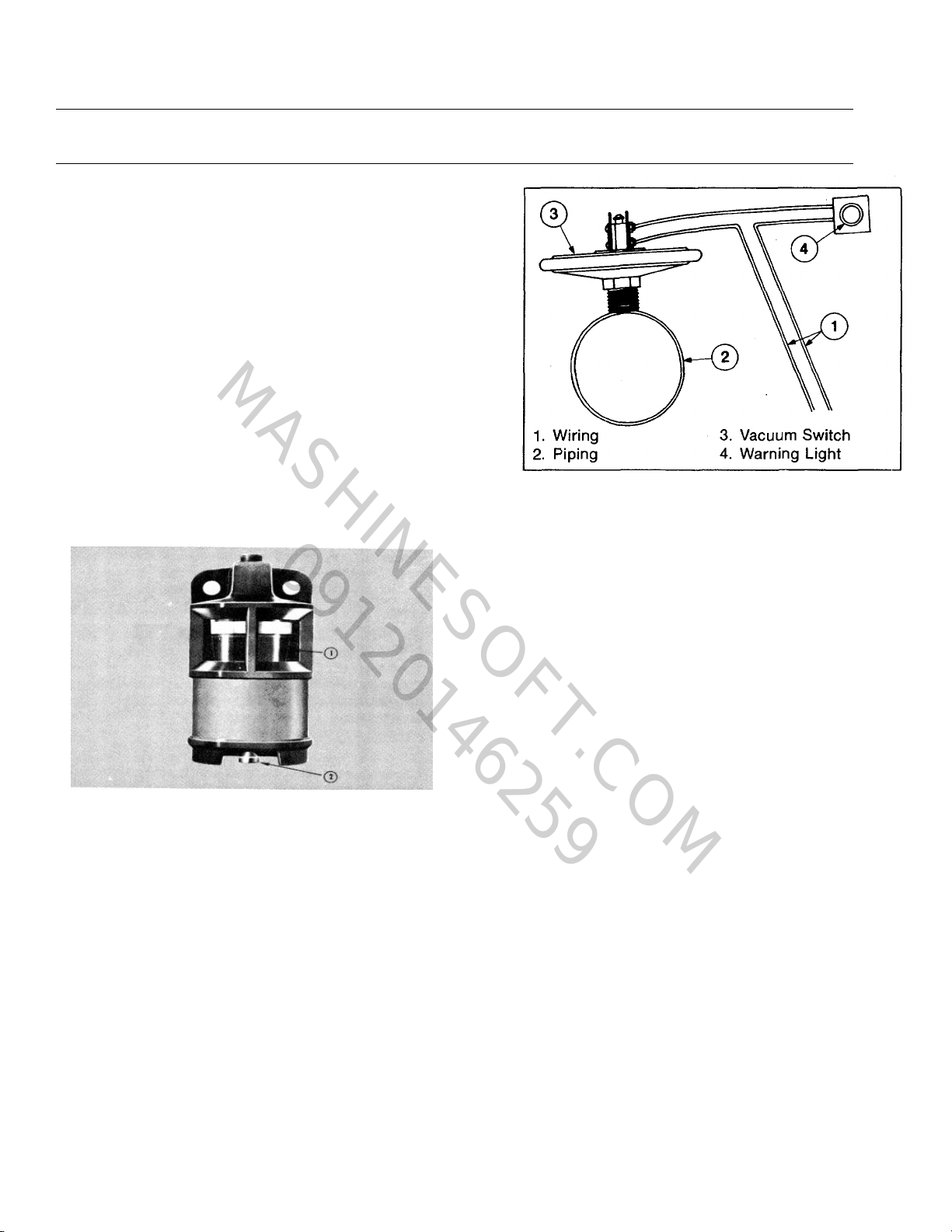
Vacuum Indicator
Vacuum switches, Fig. 2-8, are available which actuate
a warning light on the instrument panel when the air
restriction becomes excessive.
using air to blow off dirt or by washing with nonsudsing
household detergent and water at 120 to 1400F [49 to
600C], then drying with compressed air, approximately
30 psi [306 kPa]. Do not hold the air jet too close to the
paper element.
Elements that have been cleaned several times will
finally clog and air flow to the engine will be restricted.
After cleaning, check the restriction as previously
described and replace the element if necessary.
Caution: Holes, loose end seals, dented sealing
surfaces and other forms of damage render the
cleaner inoperative and require immediate element
replacement.
To change the element:
1. Loosen the wing nut (1, Fig. 2-9) securing the
2-11
30
Page 31

Operation and Maintenance
MASHINESOFT.COM
09120146259
Construction and Industrial
Fig. 2-10, (OM1031L). Changing air cleaner element Fig. 2-11. (OM1029L). Air cleaner-heavy duty
Figure 2-10. (OM1030L). Air cleaner-heavy duty element
bottom cover (2) to the cleaner housing (3).
Remove the cover.
2. Pull the element (6) down from the center bolt (4).
Fig. 2-12, (OM1030L). Air cleaner-heavy duty dual
element
Caution: Pull the cover and the element straight out
when removing them from the housing, Fig. 2-10, to
avoid damage to the element.
2-12
Page 32

3. Remove the gasket (5) from the outlet end (7) of
MASHINESOFT.COM
09120146259
he housing.
When installing the element, make sure it seats on the
gasket at the air cleaner outlet end.
Heavy Duty Dry-Type Air Cleaners
Heavy duty air cleaners (single and dual types) combine
centrifugal cleaning with element filtering, Fig's. 2-11
and 2-12, before air enters the engines.
Before disassembly, wipe dirt from the cover and the
upper portion of the air cleaner. To clean single or dual
types:
1. Loosen the wing bolt, remove the band securing
the dust pan (1, Fig. 2-11), (2, Fig. 2-12).
2. Loosen the wing nut (2, Fig. 2-11 and 3, Fig. 2-
12), remove the dust shield (3, Fig. 2-11), (4,
Fig. 2-12), from the dust pan (1, Fig. 2-11), (2,
Fig. 2-12), clean the dust pan and shield.
3. Remove the wing nut (2, Fig. 2-11), (5, Fig. 2-
12) securing the air cleaner primary element (6,
Fig. 2-12) in the air cleaner housing, inspect the
rubber sealing washer on the wing nut (4, Fig.
2-11), (5, Fig. 2-12).
4. Blow out the element from the clean air side
with compessed air not exceeding 30 psi [207
kPa].
5. Wash the element with nonsudsing household
detergent and water, 120 to 140° F [49 to 60°
C]. Dry with compressed air, 30 psi [207 kPa].
6. Inspect the element after cleaning.
7. Install a new or the cleaned primary element.
8. Be sure the gasket washer is in place under the
wing nut before tightening.
9. Reassemble the dust shield and dust pan,
position them to the air cleaner housing and
secure with the band.
10. On the dual element type Cyclopac cleaner:
a. Check the air restriction indicator. If the air
restriction is excessive, disassemble the
air cleaner, remove the wing nut (8, Fig.
2-12), and replace the safety element
(9).
b. Reassemble the air cleaner as described in
"Steps 8 and 9" above. Cartridge Type
Air Cleaner Element
1. Loosen the wing nuts (4, Fig. 2-13or2-14) on
the air cleaner housing (5) to remove the precleaner
Fig 2-13. (N21026). Air cleaner - cartridge type (two
stage)
Fig. 2-14, (V11009). Air cleaner- cartridge type (single
stage)
panel with the dust bin (1). To remove the precleaner panel (2) equipped with an exhaust
aspirator loosen the "U" bolt clamp securing
the pre-cleaner to the aspirator tubing.
2. Remove the dirty Pamic cartridge (3), by
inserting your fingers in the cartridge opening
(loosen all four corners of the cartridge, one at
a time) and pulling it straight out.
With the larger cartridge, it may be necessary to break
the seal along the edges of the cartridge. After the seal
has been broken, pull the cartridge straight out and
slightly up so the cartridge will clear the sealing frame
and edges of the air cleaner housing.
Cleaning and Inspection
1. Clean the pre-cleaner openings (2) of all soot,
oil film and any other objects that may have
become lodged in the openings. Remove any
dust or dirt in
Maintenance Instructions
2-13
Page 33

Operation and Maintenance
MASHINESOFT.COM
09120146259
Construction and Industrial
the lower portion of the pre-cleaner and aspirator
tubing. Inspect the inside of the air cleaner
housing for foreign material.
2. Inspect the dirty cartridge for soot or oil. If there is
soot inside the Pamic tubes, check for leaks in the
engine exhaust system, exhaust "blow-back" into
the air intake and exhaust from other equipment. If
the cartridge appears "oily", check for fumes
escaping from the crankcase breather. Excessive
oil mist shortens the life of any dry-type cartridge.
Troubleshooting at this point can appreciably
lengthen new cartridge life.
3. It is not recommended to clean and reuse the
cartridge. When returned to service, life
expectancy of a paper cartridge will be only a
fraction of the original service life.
4. Inspect clamps and flexible hose or tubing to be
sure all fittings are air tight on cleaners with
exhaust aspirators.
5. The pre-cleaner dust bin is self-cleaning.
Assembly
1. Inspect the new filter cartridge for shipping damage
before installing.
2. To install a new cartridge, hold the cartridge (3,
Fig. 2-13 and 2-14) in the same manner as when
removing it from the housing. Insert the clean
cartridge into the housing; avoid hitting the
cartridge tubes against the sealing flange on the
edges of the air cleaner housing.
3. The cleaner requires no separate gaskets for seals;
therefore, care must be taken inserting cartridge to
insure a proper seat within the cleaner housing.
Firmly press all edges and corners of the cartridge
with your fingers to effect a positive air seal against
the sealing flange of the housing. Under no
circumstances should the cartridge be pounded or
pressed in the center to effect a seal.
4. Replace the pre-cleaner panel (2) and tighten the
wing nuts (4) by hand, for final tighteness turn 1-1/2
to 2 turns with a small adjustable wrench. Do not
overtighten. On a pre-cleaner with an exhaust
aspirator, assemble the aspirator tube to the precleaner panel and tighten the "U" bolt.
5. Care should be taken to keep the cleaner face
unobstructed.
Change Oil Bath Air Cleaner Oil
Before dirt build-up reaches 1/2 inch [12.7 mm], remove
the oil cup from the cleaner. Discard the oil
and wash the cup in cleaning solvent or fuel oil.
Note: During wet weather and in winter months,
changing of the oil is equally as important as during
dusty weather since the air cleaner inlet may be located
in an air stream which carries moisture into the cleaner.
Fill the oil cup to the level indicated by the bead on the
side with clean, fresh oil of the same grade as that in the
crankcase and assemble it to the cleaner. In extremely
cold weather a lighter grade may be necessary. A
straight mineral, non-foaming detergent, or non-foaming
additive oil may be used in oil bath air cleaners.
Caution: Never use dirty oil or used oil.
Drain Air Tanks
In cold weather, condensed moisture in the air tanks and
lines may freeze and make controls useless. Drain the
air tanks to keep all water out of the compressed air
system.
Drain Sediment from Fuel Tanks
Loosen the fuel tank drain cock or plug, if used, and
drain approximately 1 cup of fuel to remove water and
sediment. Close the drain cock or plug.
Fuel/Water Filter Separator
If more moisture than usual is present when checking
the fuel tanks, it may be advisable to install a water
separator.
Contact the nearest Cummins Dealer for a Fleetguard
water separator that meets requirements.
Drain plugs are located in the bottom of some fuel filter
cases and in the sump of some fuel supply tanks. More
condensation of water vapor occurs in a partially filled
fuel tank than in a full one. Therefore, fuel supply tanks
should be kept as nearly full as possible. Warm
returning fuel from the injectors heats the fuel in the
supply tank. If the fuel level is low in cold weather, the
fact that the upper portion of the tank is not being
heated by returning fuel tends to increase condensation.
In warm weather both the supply tank and the fuel are
warm. In the night, however, cool air lowers the
temperature of the tank much more rapidly than the
temperature of the fuel. Again this tends to increase
condensation.
Engine Front Trunnion
If used, the engine front trunnion mount should be
lubricated with grease meeting specifications as outlined
in Section 3.
2-14
Page 34

Maintenance Instructions
MASHINESOFT.COM
09120146259
"B" Maintenance Checks
B-Check
At each "B" Maintenance Check, perform all the "A"
Checks in addition to the following.
Lubricating Oil Change Intervals
Note: If the lubricating oil is drained from the oil pan to
make an engine repair, new oil must be used. Do not
use oil after it has been drained from the oil pan.
Maintaining a proper "B" maintenance check interval is
a very important factor in preserving the integrity of an
engine. Lubricating oil contamination is the direct result
of engine operation and the load factor involved. The
amount of contamination generated depends on the
amount of fuel the engine consumes. Laboratory and
field tests have determined that, when using the
recommended quality oils and filters, a turbo-charged
engine in good condition and equipped with a bypass oil
filter can consume 255 gallons of fuel for each gallon of
oil in the oil system before the maximum level of oil
contamination is reached. Based on these findings,
Cummins Engine Company, Inc., recommends that the
"B" check interval be determined by the use of the
"Chart Method". At each "B" check interval it is
recommended to change the full-flow filter and the
bypass filter.
The total lubricating system capacity in gallons can be
determined by adding the high level of the lubricating oil
in the oil pan and the capacities of the full-flow and
bypass filters. All lubricating oil systems must be
rounded to the nearest gallon when applied to the chart.
Table 2-2 lists the capacities of the full-flow and bypass
filter elements.
Chart Method
From laboratory and field tests we know that the
maximum contamination level for a gallon of oil is
reached when 255 gallons of fuel is consumed in a
turbocharged engine or 280 gallons of fuel in a naturally
aspirated engine. The 255 or 280 figure is the constant
used in the equation for the oil change period.
Table 2-2: Lubricating Oil Filter Elements
Description
of Filter Capacity Engine
(Element P/N) (Gals.) Family
Full-flow 0.93 All Engines (except
(LF516) V-378 and V-504)
Full-flow 0.83 V-378 & V-504 Only
(LF613)
Full-flow 0.80 All Engines
spin-on (LF670) (Optional on V-555)
Full-flow 0.65 Standard on All
(spin-on short) Small Vee
(LF670-SC)
Bypass, 750 in3 2.91 All Engines
(LF750-A) (Except Small Vee)
Bypass, 750 in3 2.91 All Engines
(LF750-C) (Except Small Vee)
Bypass, 750 in3 2.91 All Engines
(LF750) (Except Small Vee)
Bypass, 500 in3 2.25 Small Vee Only
(LF500)
Bypass, spin-on 0.70 C & I Engines and
(LF777) Small Vee
Full-flow 0.50 Standard on All
Small
spin-on Vee (Will replace
(LF734) LF670-SC)
Assume a VT-1710 engine which has the following
capacities:
Lubricating Oil Pan Capacity = 18 gallons
Full-Flow Filter (3) = 2.79 gallons
Bypass Filter 750 in3 (2) = 5.82 gallons
Total Lubricating Oil = 26.61-27 gallons
System Capacity
Round this capacity to the nearest whole gallon and
select the chart entitled "Off Highway Turbocharged with
By-Pass Filter" "Lube System Capacity-27 gallons."
The following illustration is how to use the chart method
to determine the recommended oil change interval:
Also assume the average fuel consumption = 17.5
gallons per hour and the average oil consumption = 8
hours per quart.
To read the chart.
2-15
Page 35

Operation and Maintenance
MASHINESOFT.COM
09120146259
Construction and Industrial
Change Period = Constant x fuel consumed x the oil available.
Oil Available = Oil system capacity + one-half the make-up oil added in a given period.
Oil Added = Change Interval
Oil Consumption Rate
Change Period = The Constant x the fuel consumed x [the system capacity + one-half (the Change Period)
(Oil Consumption Rate)
Solving this equation for the oil change period gives
the equation which is used in developing the Chart
Method.
Change Period = Constant x fuel consumed x oil consumption x system capacity
Oil consumption - one-half (constant x fuel consumed)
1. The numbers along the left side of the chart
represent fuel consumption in gallons per hour.
Divide the grid between "10" and "20" in 10 equal
parts to find the point for fuel consumption.
2. Beginning at "17.5" (fuel consumption), draw a line
from left to right to the curve "8". This curve
represents oil consumption at the rate of 8 hours
per quart.
3. From the point on the curve "8", draw a line
perpendicular to the bottom of the chart. The
numbers across the bottom of the chart represent
the oil change interval in hours.
4. The perpendicular line from the curve "8" intersects
the bottom line of the chart between "500" and
"600". Divide the grid in 5 equal parts to find the
point for the recommended oil change interval. In
this example the recommended oil change interval
is 505 hours.
Since it is not practical with a group of engines to use a
different oil change interval for each engine based on
the chart method, Cummins recommends that you use
the chart method in the following manner:
1. Divide the engines into groups by engine model
(engines with the same lube system capacity).
2a. Determine the average fuel consumption for all the
engines in each group.
b. Select a group fuel consumption, for entering the
chart, that is halfway between the average fuel
consumption and the highest fuel consumption in
the group.
3a. Determine the average lube oil consumption for all
the engines in the group.
b. Select a group lube oil consumption for entering
the chart that is halfway between the average lube oil
consumption and the lowest oil consumption in the
group.
4. Read the appropriate chart for each group using
the fuel consumption determined in 2b and the lube oil
consumption determined in 3b. The oil change interval
determined in this manner should be applied to the
entire group.
5. Since some will have more than one group of
engine models, a change interval should be determined
for each group. In some cases it may be wise to divide
some groups into sub-groups (such as older NTC-290's
and newer Formula 290's) for which a change interval is
determined.
6. Practically, now, a manager must review the oil
change intervals determined for each group or
OIL CHANGE INTERVALS
2-16
Page 36

subgroup; consider the other items in his
MASHINESOFT.COM
09120146259
preventative maintenance schedule; consider his
own past practice; and select an oil change interval
which he feels is the best compromise.
Note: Cummins Engine Co., Inc., does not recommend
exceeding 25,000 miles and/or 600 hours on oil change
intervals. Therefore, the charts or limited to 25,000
miles or 600 hours and must not be extended.
The charts for determining the recommended oil change
intervals are included in the following pages.
Chart Method Alternative
As an alternative to the Chart Method for determining
the "B" maintenance check interval, Cummins Engine
Co., Inc., recommends that the "B" check be performed
every 10,000 miles, 250 hours or 6 months.
Note: Perform the "B" check in 6 month intervals for
engines in emergency or standby operations and any
other operation where less than the recommended miles
or hours have been accumulated in a 6 month interval.
Maintenance Instructions
2-17
Page 37

Operation and Maintenance
MASHINESOFT.COM
09120146259
Construction and Industrial
OFF HIGHWAY - NATURALLY ASPIRATED WITH BY-PASS FILTER
2-18
Page 38

Maintenance Instructions
MASHINESOFT.COM
09120146259
OFF HIGHWAY - NATURALLY ASPIRATED WITH BY-PASS FILTER
2-19
Page 39

Operation and Maintenance
MASHINESOFT.COM
09120146259
Construction and Industrial
OFF HIGHWAY - TURBOCHARGED WITH BY-PASS FILTER
2-20
Page 40

Maintenance Instructions
MASHINESOFT.COM
09120146259
OFF HIGHWAY - TURBOCHARGED WITH BY-PASS FILTER
2-21
Page 41

Operation and Maintenance
MASHINESOFT.COM
09120146259
Construction and Industrial
OFF HIGHWAY - TURBOCHARGED WITH BY-PASS FILTER'
2-22
Page 42

Maintenance Instructions
MASHINESOFT.COM
09120146259
OFF HIGHWAY - TURBOCHARGED WITH BY-PASS FILTER
2-23
Page 43

Operation and Maintenance
MASHINESOFT.COM
09120146259
Construction and Industrial
OFF HIGHWAY - TURBOCHARGED WITH BY-PASS FILTER Construction and Industrial
2-24
Page 44

Maintenance Instructions
MASHINESOFT.COM
09120146259
OFF HIGHWAY - TURBOCHARGED WITH BYPASS FILTER
2-25
Page 45

Operation and Maintenance
MASHINESOFT.COM
09120146259
Construction and Industrial
Lubricating Oil Analysis
An alternate method for determining when to change
lubricating oil and filters is by used oil analysis using
laboratory tests. The analyses used are for the purpose
of determining the amount of contamination in the oil;
not for predicting potential engine failures. It is
recommended that new engines be operated through at
least one oil change interval determined by the chart
method prior to initiating a used oil analysis program.
In order to initiate a used oil analysis program for a large
number of engines they should be grouped by basic
model, rated horsepower and type of service. The
horsepower range of a group should not exceed 25; in
other words NTC-270 and NTC-290 engines could be
placed in the same group, however, NTC-290 and NTC350 engines should be in separate groups. Small vee,
medium vee, NH and K models should be in separate
groups. After the engines have been grouped, a subgroup consisting of 10 percent of the total engines in
each group should be selected for the used oil analysis
program. If a group consists of less than 50 engines but
more than 25 engines the sub-group size should be 5
engines. For groups of less than 25 engines the subgroup size should be 8 engines. The selecting of the
engines for each subgroup should be completely
random.
Each group of engines should be set up on oil change
intervals as described under the "Chart Method". When
the engines reach the end of the second chart method
oil change interval, an oil change should be performed
on all units in the group except those engines selected
for the sub-group. The engines in the sub-groups should
only have an oil sample taken. Additional oil samples
should be taken from each of the engines in the subgroups at every 48-operating- hour interval after the first
sample. This sampling frequency may be varied
somewhat as dictated by the operation. The sampling
frequency should not be extended beyond 60 hours for
equipment safety reason or reduced below 40 hours
because of the added analytical costs.
analytical results should be done as quickly and
carefully as possible to prevent serious engine damage.
Table 2-3: Lubricating Oil Condemnation Limits
Property (ASTM Method*) Condemnation Limit
Viscosity @ 100° C + 1 SAE Viscosity grade**
(D445) from the new oil
Insolubles, pentane, 1.0% maximum
noncoagulated
(D-893)
Insolubles, toluene, 1.0% maximum
noncoagulated
(D-893)
Total acid number 3.5 number increase from
(D-664) the new oil value, maximum
Total base number 2.0, minimum
(D-664)
Water content 0.2% maximum
(D-95)
Additive metal content 75% of new oil level,
(AES or AAS'*) minimum
*ASTM (The American Society for Testing and
Materials) publishes these methods in their Annual Book
of Standards, Part 23. Other methods should not be
used without consulting Cummins.
**SAE Viscosity grades are published by the Society of
Automotive Engineers in their annual SAE Handbook as
SAE Recommended Practice J300d, and are shown in
Table 1 of this bulletin.
***AES (Atomic Emission Spectroscopy) and AAS
(Atomic Absorption Spectroscopy) are not standard
ASTM methods, however most used oil analysis
laboratories are capable of determining additive metal
concentration by one of these methods and sample
results determined by the same laboratory using the
same method can be safely compared.
This sampling process should continue until the results
of the analyses of the samples indicate that any one of
the condemnation limits listed in Table 2-3 has been
reached or exceeded until the desired oil change
interval extension is reached. This process should be
continued cautiously since the engines in the subgroups
are subject to permanent damage because of the overextended oil change interval. The analytical work on the
samples and the examination of the
To determine whether the maximum oil change interval
has been reached the properties in Table 2-3 should be
determined by the laboratory methods specified. This
table also specifies condemnation limits to be used for
determining the lubricating oils' useful life. This group of
analyses and the methods are not generally part of the
oil analyses offered by most
2-26
Page 46

Maintenance Instructions
MASHINESOFT.COM
09120146259
commercial used oil analysis laboratories. These
analyses are not low cost, generally costing between
$50 and $135 per sample.
When any one of the condemnation limits is exceeded
on any one sample an oil change should be performed
on all engines in the sub-group. The hours at which the
sample for which a condemnation limit was exceeded is
the oil change interval at which 10% or more (depending
on sub-group size) of the group are using lubricating oil
which has exceeded its useful life. This sampling and
analysis process should be repeated once to confirm the
oil change interval. When this process is complete the
entire group of engines can be placed on the new oil
change interval.
This method of establishing an oil change interval will
determine a different interval for each group of engines.
It is not possible to provide maintenance on several
different schedules or if one desires to schedule the oil
change to coincide with other maintenance, the more
conservative (or shorter) maintenance schedule should
be used.
Please contact your Cummins Service Representative if
you need assistance or have any questions about
utilizing this method of determining an oil change
interval.
Change Engine Oil
Factors to be checked and limits for oil analysis are
listed below. Oil change at "B" Check, as shown in the
maintenance chart on Page 2-2, is for average
conditions.
1. Bring engine to operating temperature, shut down
engine, remove drain plug from bottom of oil pan,
and drain oil.
Note: Use lubricating oil meeting specifications listed in
Section 3, and genuine Cummins filters on equipment.
Change Spin-On Lubricating Oil Filter Elements
1. Unscrew combination case and elements, Fig. 2-15,
discard elements.
Fig. 2-15, (OM1018L). Installing lubricating oil filter
cartridge
Note: At each filter change check torque of adapter
mounting capscrew; it should be 25 to 35 ft-lbs [34 to 47
N•m]. If the capscrew is not within torque range, the
adapter may rotate when the spin-on filter is removed.
Replace the adapter to the filter head gaskets at each
"C" maintenance check.
2. Fill the filter with lubricating oil. Apply a light even
coat of lubricating oil to the gasket sealing surface prior
to installing the filter.
2. Install drain plug in oil pan. On 855, V-903, KT(A)-
1150, KT(A)-2300 and KT(A)-3067 engines torque to
60 to 70 ft-lbs [81 to 95 N•m]. On V-378, V-504 and
V-555 engines torque to 35 to 40 ft-lbs [47 to 54
N•m]. On V-1710 engines torque to 45 to 55 ft-lbs
[61 to 75 N•m].
3. Fill the crankcase to "H" (high level) mark on the
dipstick.
4. Start engine and visually check for oil leaks.
5. Shut down the engine; allow 15 minutes for oil to
drain back into the pan; recheck the oil level with
the dipstick. Add oil, as required.
2-27
Fig. 2-16, (K21907). Installing "spin-on" lubricating
oil filter - KT(A)-2300 Engine
Page 47

Operation and Maintenance
MASHINESOFT.COM
09120146259
Construction and Industrial
3. Position element to the filter head, Fig. 2-16.
Tighten by hand until the seal touches the filter
head, tighten an additional one-half to three-fourths
turn.
4. Run the engine, check for leaks, recheck engine oil
level; add oil as necessary to bring the oil level to
"H" mark on the dipstick.
Note: Always allow oil to drain back to the oil pan
before checking the level. This may require 15 minutes.
Change the LF--777 Lubricating Oil Spin-On
By-pass Filter.
1. Unscrew the spin-on filter from the filter head;
discard the filter.
2. Apply a light even coat of lubricating oil to the
gasket sealing surface, prior to installing the filter.
3. Position the filter to the filter head. Tighten by hand
until the seal touches the-filter head; tighten an
additional one turn.
4. Run the engine, check for leaks, shut-down the
engine. Add oil as necessary to bring the oil level to
the "H" mark on the dipstick.
Change Lubricating Oil By-Pass Filter Element
Note: By-pass filters may be mounted either vertically,
horizontally or inverted; all are serviced in like manner.
1. Remove the drain plug (5, Fig. 2-17) and drain oil.
2. Remove the clamping ring capscrew (1) and lift off
the cover.
3. Unscrew the support hold-down assembly (3); lift out
the element (4) and the hold-down assembly.
Discard the element.
4. Clean the housing and hold-down assembly in
solvent.
5. Inspect the hold-down assembly spring and seal.
Replace if damaged.
6. Inspect the drain plug and connections. Replace if
damaged.
7. Check the orifice plug (6) inside the oil outlet
connection or standpipe; blow out with air to open
and clean.
8. Check the filter cover O-ring (7). Replace if
necessary.
9. Install the new element in the housing, Fig. 2-18.
Fig. 2-17, (V41908). By-pass filter cross section
10. Replace the support hold-down assembly in the filter
and tighten down to stop.
11. Position the O-ring seal on the housing flange.
12. Install the cover and clamping ring; tighten the
capscrews until the clamping lugs are indexed.
13. Run the engine, check for leaks; add enough extra
oil to the crankcase to fill to the "H" (high) mark on
the dipstick.
Fig. 2-18, (K21908). Installing by-pass filter element
2-28
Page 48

Maintenance Instructions
MASHINESOFT.COM
09120146259
Caution: Never use a by-pass filter in place of a fullflow filter.
Change Fuel Filter Element
Spin-On Type Filter
1. Unscrew the combination case and element, Fig. 219, discard the element.
2. Fill the new filter with clean fuel and apply a light
even coat of lubricating oil to the gasket sealing
surface prior to installing the filter.
3. Install the filter; tighten by hand until the seal
touches the filter head. Tighten an additional onehalf to three-fourths turn.
Replaceable Element
1. Open the drain cock(s) and drain the contents.
2. Loosen the nut(s) at the top of the fuel filter(s).
Take out the dirty element, clean the filter case(s)
and install new element(s). Fig. 2-20.
3. Install new gasket(s) in the filter(s) and assemble
the case(s) and element(s). Tighten center bolt(s) to
20 to 25 ft-lbs [27 to 34 N•m] with a torque wrench.
Fill the filter case(s) with clean fuel to aid in faster
pick-up of fuel.
4. Check the fittings in the filter head(s) for leaks.
Fittings should be tightened to 30 to 40 ft-lbs [41 to
54 N•m].
Check Engine Coolant
Periodic tests of the engine coolant should be made to
ensure that the frequency of water filter servicing or
concentration of DCA inhibitor is adequate to control
corrosion for any specific condition of operation. In
cases where "make-up" water must be added frequently,
we suggest that a supply of water be treated and added
as necessary.
The concentration of effective inhibitor dissolved in
Fig. 2-19, (Vl1909). Changing "spin-on" type fuel filter
Caution: Mechanical tightening will distort or crack
the filter head.
Fig. 2-20, (OM1021L). Installing replaceable
fuel filter element
Fig. 2-21, (N12021). DCA coolant test kit
2-29
Page 49

the coolant can be measured by a Fleetguard DCA
MASHINESOFT.COM
09120146259
Coolant Checking Kit Part No. 3300846-S or Cummins
3375208 which is available from Cummins Distributors
for this check. Fig. 2-21.
The test kit indicates DCA concentration by measuring
the total nitrite of a coolant sample, which provides
cylinder liner cavitation protection.
When antifreeze is present, it may contribute to the total
nitrite, but most of the nitrite protection is obtained from
the DCA inhibitor. In general, a good nitrite reading
indicates that the combined inhibitor packages
contained in the antifreeze (if used) and in DCA are
sufficient to ensure complete cooling system protection.
Concentration Test Procedure
1. Rinse the plastic dropper pipette several times with
the engine coolant. Fill the dropper exactly to the
1.0 ml. mark. Discharge into the empty vial.
Operation and Maintenance
Construction and Industrial
Fig. 2-22, (V12022). Mixing bottle
5. Continue adding drops of solution A, keeping count
of the number of drops and swirl between each drop
until the color changes from red to a pale grey,
green, or blue.
2. Fill the vial to the 10 ml. scribe mark with tap water
and mix well. (This dilution step is necessary to
minimize the differing colors of antifreeze.)
3. Add two or three drops of Solution B and swirl to
form a uniform red color.
4. Add one drop of Solution A to the vial, being careful
to hold the dispenser in a vertical position. Swirl.
Coolant With Coolant Without
Antifreeze Antifreeze Coolant Condition Maintenance Required
0-12 0-6 Dangerous (0 to 0.6 oz. Precharge system or add
Table 2-4. Number of Drops of Test Solution "A"
per gallon DCA) make-up DCA to top tank
6. Record the number of drops required for the color
change and consult Table 2-4 for coolant condition
and recommended maintenance.
Adding Make-Up Coolant and DCA
to Cooling System
1. Test the coolant for DCA according to the nitrite test
procedure 'With or Without Antifreeze"
12-17 7-12 Borderline (0.7 to 1.2 oz. Replace service filter and/or
per gallon DCA) add make-up DCA to top tank.
18-25 13-20 Acceptable (1.3 to 2.0 oz. None.
per gallon DCA)
25-30 20-30 Tolerable (2.0 to 3.0 oz. None.
per gallon DCA)
Over 30 Over 30 Overrated (over 3.0 per Drain part of coolant and
gallon DCA) make-up with plain antifreeze
and water.
Note: Ethylene glycol/water solutions should not contain more than 3.0 oz. per gallon DCA or Dowtherm 209/water
solutions should not contain more than 2.0 oz. per gallon DCA. Concentrations in excess of the above can cause sludge to
form in the water filter.
2-30
Page 50

Maintenance Instructions
MASHINESOFT.COM
09120146259
depending on the presence or absence of antifreeze
in the cooling system.
2. Estimate the make-up DCA. For example, if a
fifteen gallon cooling system contains only 0.5
oz/gal. [4 ml per I] DCA, and 1.5 oz/gal. [12 ml per
I] is required, 15 ounces [426 g] of DCA should be
added to the make-up coolant.
Note: A one pint bottle of DCA-4L liquid (P/N 3300858)
contains six dry ounces of DCA chemical in Step 2,
concentrations are in dry ounces of chemical per gallon
of coolant.
3. Estimate the total amount of make-up coolant
required (gallons), and calculate the proportions of
water and antifreeze, if used, required. For
example, one gallon of 50-50 antifreeze/water
solution will require two quarts of antifreeze and two
quarts of water.
4. Add the required amount of water to a mixing
container and dissolve the number of ounces of
DCA obtained in Step 2 in the water. If negative or
zero results were obtained in Step 2, do not add
DCA. (For DCA to dissolve, water should be above
50°F [10°C].)
5. Add the required amount of antifreeze, if used, to
the water solution and mix thoroughly.
6. Add the make-up coolant to the cooling system.
Note: If the DCA concentration is low, and the coolant
level high, DCA may be added directly to the radiator in
the amount indicated in Step 2. The engine should be
running and warm enough to permit coolant circulation
throughout the entire system.
Bulk Storage of Make-Up Coolant
If make-up coolant is stored in bulk, the following
recommendations are provided for mixing and storing
the coolant.
Multiplying 1.5 oz. DCA per gallon [12 ml per I]
times 500 gallons [1892 l] yields a total DCA
requirement of 750 oz. [46 lb. 14 oz.] [21.3 kg].
4. Add the water to the holding tank. Agitating
continuously, add the DCA to the water in small
amounts until all of the chemical has dissolved. The
water should be above 50°F [10°C].
5. Add the antifreeze last, if used, maintaining
agitation to bring and keep the finished coolant in
solution. Both antifreeze and DCA will settle to the
bottom of the tank unless constant mixing or
recirculation is provided. An example of
recirculation is the use of a small pump operating
continuously to draw DCA and antifreeze off the
bottom of the tank and discharging the solution at
the top. Samples of coolant can be drawn off the
top, middle and bottom of the storage tank and
tested for antifreeze and/or DCA concentration if
inadequate mixing is suspected.
Change DCA Water Filter
Change the filter or element at each "B" Check;
selection of element to be used should be based upon
the size of the system. See "Coolant Specifications",
Section 3.
Note: Whenever the coolant supply is changed the
system must be drained, flushed, and precharged. See
"Coolant Specifications", Section 3 for DCA
compatibility with different brands of antifreeze.
Spin-On Element
1. Close the shut-off valves on inlet and drain lines.
2. Unscrew the element and discard.
3. Apply a light even coat of lubricating oil to the
1. Drain and clean the bulk storage tank to remove any
possible contaminants.
2. Knowing the total capacity of the holding tank,
calculate the proportions of water and antifreeze, if
used, required. For example, a 500 gallon [1892 l]
tank will hold 250 gallons [946 I] of water and 250
gallons [946 l] of antifreeze for a 50-50 mixture.
3. Multiply the desired DCA concentration by the total
capacity of the holding tank in gallons. In the
example above, 1.5 oz. DCA per gallon [12 ml per I]
of coolant can be used in the 50-50 mixture.
Fig. 2-23, (OM1023L). Installing DCA water filter
cartridge
2-31
Page 51

Operation and Maintenance
MASHINESOFT.COM
09120146259
Construction and Industrial
gasket sealing surface prior to installing the filter.
4. Install a new element, tighten until the seal touches
the filter head. Tighten an additional one-half to
three-fourths turn. Fig. 2-23. Open shut-off valves.
Caution: Mechanical tightening will distort or crack
the filter head.
Check Oil Levels
Check Aneroid Oil
1. Remove the pipe plug from hole marked "Lub Oil".
2. Fill with engine lubricating oil to the level of the pipe
plug hole. Reinstall the pipe plug.
Check Hydraulic Governor Oil Level
Keep the level half-way up on the inspection glass or to
the high-level mark on the dipstick. Use the same grade
oil as used in the engine.
Clean/Change Crankcase Breather
baffle if used, from the breather body. Fig. 2-25.
Mesh Element Breather
1. Remove the wing nut (6, Fig. 2-24), flatwasher and
rubber washer securing the cover (1), to the
breather body (5).
2. Lift off the cover and life out the breather element
(2), vapor element (3), and gasket (4).
3. Clean all metal and rubber parts in an approved
cleaning solvent. Dry thoroughly w/compressed air.
4. Inspect the rubber gasket; replace it if necessary.
Inspect the body and cover for cracks, dents or
breaks; discard all unserviceable parts.
5. Install cleaned or new breather element (2, Fig 2-24)
and cleaned vapor element (3) to breather body (5).
6. Install the rubber gasket (4) in the cover (1); position
the cover assembly to the body (5).
7. Install the rubber washer, flatwasher and wing nut
(6); tighten securely.
Screen Element Breather - Cleaning and Inspection
Fig. 2-24, (V51909). Crankcase breather mesh element
with vapor barrier
Fig 2-25, (N11934). Crankcase breather - screen type
3. Clean the vent tube, screens and baffle in an
approved cleaning solvent. Dry with compressed
air. Wipe out the breather housing.
4. Assemble the baffle and screens, if used, and a new
gasket in the body.
1. Remove the vent tube if not previously removed.
2. Remove capscrews, washers, cover, screens and
5. Replace the cover with the cover boss resting
2-32
Page 52

Maintenance Instructions
MASHINESOFT.COM
09120146259
securely on the point of the screen, if used; secure
with washers and capscrews.
6. Replace the vent tube.
Clean Air Compressor Breather
When used, service breathers regularly as follows:
Bendix-Westinghouse Paper Element
Remove the breather cover and element. Fig. 2-26.
Clean by reverse flushing with compressed air;
reassemble on the compressor. Discard the element if it
is damaged or unsuitable for cleaning.
Fig. 2-26, (V41420). Bendix-Westinghouse air
compressor breather
Clean the body and front cover with a clean cloth. With
the rubber gasket on center bolt, place the element in
the front cover and assemble over the center bolt;
secure with the wing nut.
Fig. 2-27, (V414209). Cummins air compressor breather
paper element
Note: At any time the three-prong unloader hat is used,
it will set up air pulsations across the compressor intake
which can destroy the paper element. Pipe intake air for
Cummins compressors from the engine air manifold
when the three-prong unloader hat is applied; current
factory-installed compressors are so equipped. This
same procedure may be used for any Cummins
Compressor in the Field.
Clean Tray Screen
Bendix-Westinghouse Sponge
Remove the breather from the air compressor.
Disassemble the breather, wash all metal parts in
solvent and blow dry with compressed air. Wash the
element in solvent; remove all solvent from the element;
dip it in clean engine oil and squeeze excess oil from
the element.
Cummins Paper
Clean the element at each "D" maintenance check.
Remove the wing nut securing the front cover to the
body. Lift off the front cover and element. Inspect the
paper element before cleaning by reverse flow of
compressed air; discard the element if it is damaged or
unsuitable for cleaning. Fig. 2-27.
Caution: Do not rupture the filter element.
Clean the tray screen in kerosene or cleaning solvent.
Dry with compressed air, reassemble to the cleaner.
Note: If the tray screen is extremely dirty, it may be
necessary to singe the screen with a flame. Do not melt
the tin plate on the screen.
2-33
Page 53

"C" Maintenance Checks
MASHINESOFT.COM
09120146259
Operation and Maintenance
Construction and Industrial
At each "C" Maintenance Check, first perform all "A"
and "B" Checks in addition to those following:
Adjust Injectors and Valves
It is essential that the injectors and valves be in correct
adjustment at all times for the engine to operate
properly. One controls engine breathing; the other
controls fuel delivery to the cylinders.
Final operating adjustments must be made using correct
values as stated.
Caution: Be sure the injector and valve set
markings, wherever located, are in proper alignment
with the indicator mark.
Engine Temperatures
The following temperature conditions provide the
necessary stabilization of engine components to allow
for an accurate valve and injector adjustment.
Cummins Engine Company, Inc. recommends that
valve and injector plunger adjustments be made when
the engine is cold. The engine must be at any stabilized
temperature of 140°F [60°C] or below.
A second setting or resetting after the engine is warm is
not recommended.
Valve Set Mark Alignment
1. Turn the crankshaft in direction of rotation until No.
1 "VS" mark appears on the vibration damper or
crankshaft pulley. See Fig. 2-28 for the location of
the valve set marks. In this position, both intake
and exhaust valves must be closed for cylinder No.
1; if not, advance the crankshaft one revolution.
See Fig. 2-29, Fig. 2-30 and Table 2-5 for firing
order.
Fig. 2-28, (OM1035L). Valve set marks -
V/VT-555 C.I.D. Engine
Injector Plunger Adjustment Using Torque Method,
V/VT-378, V/VT-504, V/VT-555 Engines
The injectors and valves must be in correct adjustment
at all times for the engine to operate properly. This
controls engine breathing and fuel delivery to the
cylinders. Final adjustment must be made when the
engine is at operating temperature. The injectors must
always be adjusted before the valves. The procedure is
as follows:
2-34
Fig. 2-29, (V11461). V6 firing order
Page 54

Fig 2-30, (V11462). V8 firing order
MASHINESOFT.COM
09120146259
Note: Do not use the fan to rotate the engine.
Maintenance Instructions
contacts the cup and advance an additional 15
degrees to squeeze the oil from the cup.
2. Adjust the injector plunger, then the crossheads and
valves of the first cylinder as explained in
succeeding paragraphs. Turn the crankshaft in the
direction of rotation to the next "VS" mark
corresponding to the firing order of the engine and
the corresponding cylinder will be ready for
adjustment. See Table 2-5.
3. Continue turning the crankshaft in the direction of
rotation and making adjustments until all injectors
and valves have been correctly adjusted.
Table 2-5. Engine Firing Order V Engines
Right Hand V8 1-5-4-8-6-3-7-2
Right Hand V6 1-4-2-5-3-6
Note: Two complete revolutions of the crankshaft are
needed to set all injector plungers and valves. The
injector and valves can be adjusted for only one cylinder
at any one "VS" setting.
Injector Plunger Adjustment
Fig. 2-31, (OM1037L). Adjusting injector plunger
2. Loosen the adjusting screw one turn. Using a torque
wrench calibrated in in-lbs and a screwdriver adapter,
tighten the adjusting screw to the values shown in Table
2-6 for cold setting and tighten the locknut.
Table 2-6. Injector Plunger Adjustment Torque
V/VT-378, V/VT-504, V/VT-555 Engines
Oil Temperature Oil Temperature
Cold Hot
60 in-lbs [6.8 N•m] 60 in-lbs [6.8 N•m]
Before adjusting the injector, tighten the injector
holddown capscrew to 30 to 35 ft-lbs [41 to 47 N•m].
The injector plungers of all engines must be adjusted
with an in-lb torque wrench to a definite torque setting.
Snap-On Model TQ12B or equivalent torque wrench and
a screwdriver adapter can be used for this adjustment.
Fig. 2-31.
1. Turn the adjusting screw down until the plunger
Fig 2-32 (OM1038L). Tighten injector adjusting screw
locknut
3-35
Page 55

Operation and Maintenance
MASHINESOFT.COM
09120146259
Construction and Industrial
Note: After all the injectors and valves are adjusted
and the engine has been started and warmed up to
140°F [69°C] oil temperature, reset the injectors to the
warm setting. This is only necessary if the injectors,
lever assemblies, or push rods have been changed.
3. Hold the injector adjusting screw and tighten the
injector adjusting screw locknut to the values
indicated in Table 2-7.
When an ST-669 Adapter is used, nut torque is reduced
to compensate for additional torque arm length. Fig. 2-
32.
Table 2-7. Injector and Valve Locknut Torque
V/VT-378, V/VT-504, V/VT-555 Engines
Without ST-669 With ST-669
40 to 45 ft-lbs. 30 to 35 ft-lbs.
[54 to 61 N•m] [41 to 47 N•m]
Crosshead Adjustment
Crossheads are used to operate two valves with one
rocker lever. The crosshead adjustment is provided to
assure equal operation of each pair of valves and
prevent strain from misalignment.
1. Loosen the valve crosshead adjusting screw locknut
and back off the screw one turn.
2. Use light finger pressure at the rocker lever contact
surface to hold the crosshead in contact with the
valve stem (without the adjusting screw).
3. Turn down the crosshead adjusting screw until tit
touches the valve stem. Fig. 2-33.
4. Hold the adjusting screw in this position and torque
the locknut to the values listed in Table 2-8.
5. Check the clearance between the crosshead and the
valve spring retainer with a wire gauge. There must
be a minimum of 0.025 inch [0.64 mm] clearance at
this point.
Valve Adjustment
The same crankshaft position used in adjusting the
injectors is used for setting the intake and exhaust
valves.
Table 2-8. Crosshead Locknut Torque
Without ST-669 With ST-669
25 to 30 ft-lbs. 22 to 26 ft-lbs.
[34 to 41 N•m] [30 to 35 N•m]
1. Loosen the locknut and back off the adjusting screw.
Insert a feeler gauge between the rocker lever and
the top of the crosshead. Valve clearances are
shown in Table 2-9. Turn the screw down until the
lever just touches the gauge and lock the adjusting
screw in this position with the locknut. Fig. 2-34.
Torque the locknut to the values indicated in Table
2-7; note Step 2 under "Injector Plunger
Adjustment".
Table 2-9: Valve Clearances - Inch [mm]
V/VT-378, V/VT-504, V/VT-555 Engines
Intake Valve Exhaust Valve
Oil Temperature Oil Temperature
Fig. 2-33, (UM1039L). Adjusting crossheads
Cold Cold
0.012 0.022
[0.30] [0.56]
V-903 Engines Injector Adjustment,
Using Dial Indicator Method
This method involves adjusting the injector plunger
2-36
Page 56

Fig. 2-34, (OM1040L). Adjusting valves
MASHINESOFT.COM
09120146259
travel with an accurate dial indicator rather than
tightening the adjusting screw to a specified torque.
The "indicator method" eliminates errors in adjustment
caused by friction in the screw threads and distortion
from overtightening the adjusting screw locknut. A
check can be made of the adjustment without disturbing
the locknut or screw setting. The valves can also be
checked or set while adjusting the injectors by this
method. See Table 2-10 for specifications.
Table 2-10. Adjustment Limits Using Dial
Indicator Method Inch [mm] V-903 Engines
Maintenance Instructions
"VS" mark for cylinder 2-8 is aligned with the pointer. In
this position both the intake and exhaust valve rocker
levers for No. 2 cylinder should be free and can be
moved up and down. If not, bar the engine another 360
degrees in the direction of rotation and realign the 2-8
"VS" mark.
Fig. 2-35, (OM1041L). Barring V-903 Engine
The timing mark locations (Figs. 2-36 and 2-37) are
used with the dial indicator method of setting the
injectors and valves. Alignment, in either location,
should be held to within one-half inch [12.7 mm] of the
pointer.
Injector Plunger Valve Clearance
Travel Intake Exhaust
1 to 1 Rocker Lever Ratio - Injector Lever P/N 211319
0.187 ± 0.001 0.012 0.025
[4.75 ± 0.03] [0.30] [0.64]
Before adjustment, tighten the injector hold-down
capscrew to 30 to 35 ft-lbs [41 to 47 N•m] torque.
Note: Remove the key, and using either a 3/8 inch hex
drive for female type barring device or a 5/8 inch sixpoint socket for the male type barring device, press
inward until the barring gear engages the drive gear;
then advance. Fig. 2-35. After completion of
adjustment, be sure the drive retracts and install the key
into the safety lock groove.
Using the regular engine barring device, Fig. 2-35,
rotate the engine in the direction of rotation with the
2-37
Fig 2-36, (OM1042L). Location of timing marks on front
cover and vibration damper
Note: No. 2 cylinder is selected for the purpose of
illustration only. Any other cylinder could be used, if so
desired.
Page 57

Fig. 2-37, (V514127). Valve set mark on
MASHINESOFT.COM
09120146259
accessory drive - V-903
Operation and Maintenance
Construction and Industrial
4. Using ST-1251 Rocker Lever Actuator, bottom the
injector plunger, check the zero (0) setting. Fig. 2-
39. Allow the plunger to rise slowly, the indicator
must show the plunger travel to be within the range
specified in Table 2-10.
1. Set up the ST-1270 Indicator Support with the
indicator extension atop the injector plunger flange
at No. 2 cylinder, Fig. 2-38.
Fig. 2-38, (V514114). Dial indicator in place - V-903
2. Screw the injector lever adjusting screw down until
the plunger is bottomed in the cup, back off
approximately 1/2 turn then bottom again, set the
dial indicator at zero (0).
Note: Care must be taken to assure the injector plunger
is correctly bottomed in the cup, without overtightening
the adjusting screw, before setting the dial indicator.
3. Back the adjusting screw out until a reading of 0.187
inch [4.75 mm], reference Table 2-10, is obtained on
the dial indicator. Snug tighten the locknut.
Fig 2-39, (V514128). Bottoming injector plunger
in cup - V-903
5. Using ST-669 Torque Wrench Adapter to hold the
adjusting screw in position, torque the locknut 30 to
35 ft-lbs [41 to 47 N•m]. If the torque wrench
adapter is not used, hold the adjusting screw with a
screwdriver, torque the locknuts 40 to 45 ft-lbs [54 to
61 N•m].
6. Actuate the injector plunger several times as a
check of the adjustment. Remove the dial indicator
assembly.
7. Adjust the valves on the appropriate cylinder as
determined in Step 1 and Table 2-10. Tighten the
locknuts the same as the injector locknut.
Crosshead Adjustment
Crossheads are used to operate two valves with one
rocker lever. The crosshead adjustment is provided to
assure equal operation of each pair of valves and
prevent strain from misalignment.
1. Loosen the valve crosshead adjusting screw locknut
and back off the screw one turn.
2. Use light finger pressure at the rocker lever contact
surface to hold the crosshead in contact with the
valve stem (without adjusting screw). Fig. 2-40.
3. Turn down the crosshead adjusting screw until it
touches the valve stem.
2-38
Page 58

Maintenance Instructions
MASHINESOFT.COM
09120146259
lever and the top of the crosshead. Fig. 2-41.
Valve clearances are shown in Table 2-10. Turn the
screw down until the lever just touches the gauge,
and lock the adjusting screw in position with the
locknut. Torque the adjusting screw locknuts to 40
to 45 ft-lb [54 to 61 N•m] or 30 to 35 ft-lb [41 to 47
N•m] when using an ST-669 Adapter.
2. Always make the final valve adjustment after the
injectors are adjusted.
NH-743, N-855, C.I.D. Engines, Injector and
Valve Adjustment (Dial Indicator Method)
Fig. 2-40, (V51490). Adjusting crossheads - V-903
4. Hold the adjusting screw in position and torque the
locknut to the values listed in Table 2-8.
Note: Be sure that the crosshead retainer on the
exhaust valves, if used, is positioned equally on both
sides of the spring over the crossheads and valve
springs properly.
5. Check the clearance between the crosshead and the
valve spring retainer with a wire gauge. There must
be a minimum of 0.025 inch [0.64 mm] clearance at
this point.
Valve Adjustment
The same engine position used in adjusting injectors is
used for setting intake and exhaust valves.
1. Loosen the locknut and back off the adjusting screw.
Insert a feeler gauge between the rocker
Note: Before adjusting the injectors and valves be sure
to determine if the rocker housings are cast iron or
aluminum and use the appropriate setting.
Before adjusting the injectors, torque the cylindrical
injector, hold-down capscrews in alternate steps to 10 to
12 ft-lbs [14 to 16 N•m]. With flange injectors torque the
hold-down capscrews in alternate steps to 12 to 14 ft-lbs
[14.6 to 18 N•m]. Tighten the fuel inlet and drain
connections to 20 to 25 ft-lbs [27 to 34 N•m] in the
flange injectors.
Maintenance Adjustment
1. Bar the engine until "A" or 1-6 "VS" mark on the
pulley, Fig. 2-42, is aligned with the pointer on the
gear case cover. In this position, both valve rocker
levers for cylinder No. 5 must be free (valves
closed). The injector plunger for cylinder No. 3 must
be at top of its travel; if not, bar the engine 360
degrees, realign the mark with the pointer.
2. Set up ST-1170 Indicator Support with the indicator
extension on the injector plunger top at No. 3
Fig. 2-41, (V51492). Adjusting valves - V-903
2-39
Fig. 2-42, (N114230). Accessory drive pulley marking -
N-855
Page 59

Fig. 2-43, (OM1051L). Extension in contact with plunger Fig. 2-44, (OM1052L). Actuating rocker lever
MASHINESOFT.COM
09120146259
cylinder, Fig. 2-43. Make sure the indicator
extension is secure in the indicator stem and not
against the rocker lever.
Note: Cylinder No. 3 for injector setting and cylinder
No. 5 for valve setting are selected for illustration
purposes only. Any cylinder combination may be used
as a starting point. See Table 2-11.
Table 2-11: Injector and Valve Set Position
N-855 Engines
Bar in Pulley Set Cylinder
Direction Position Injector Valve
Start A or 1-6VS 3
5
Adv. To B or 2-5VS 6 3
Adv. To C or 3-4VS 2 6
Adv. To A or 1-6VS 4 2
Adv. To B or 2-5VS 1 4
Adv. To C or 3-4VS 5 1
3. Using ST-1193 Rocker Lever Actuator, Fig. 2-44, or
equivalent, bar the lever toward the injector until the
plunger is bottomed to squeeze the oil film from the
cup. Allow the injector plunger to rise, then bottom
again. Set the indicator at zero (0). Check the
extension contact with the plunger top.
35 ft-lbs [41 to 47 N•m] when using ST-669 Adapter.
Table 2-12. Adjustment Limits Using Dial Indicator
Method Inch [mm] N-855 Engines
Injector Plunger
Oil Travel Valve Clearance
Temp. Inch [mm] Inch [mm]
Adj. Value Intake Exhaust
Aluminum Rocker Housing
Cold 0.170 0.011 0.023
[4.32] [0.28] [0.58]
Hot 0.170 0.011 0.023
[4.32] [0.28] [0.58]
Cast Iron Rocker Housing
Cold 0.175 0.013 0.025
[4.45] [0.32] [0.63]
Hot 0.170 0.011 0.023
[4.32] [0.28] [0.58]
NT-855 (Big Cam only - Non Top-Stop)
0.228 0.011 0.023
[5.79] [0.28] [0.58]
Note: Check engine dataplate for injector and valve
setting.
4. Bottom the plunger again, release the lever; the
indicator must show travel as indicated in Table 2-
12. Adjust as necessary.
5. If loosened, tighten the locknut to 40 to 45 ft-lbs [54
to 61 N•m] and actuate the injector plunger several
times as a check of the adjustment. Tighten to 30 to
Adjust Injectors and Valves (Torque Method)
V-1710, NH-743, N-855 C.I.D. Engines
Timing Mark Alignment
1. If used, pull the compression release lever back and
2-40
Page 60

Maintenance Instructions
MASHINESOFT.COM
09120146259
block in the open position only while barring the
engine.
2. Loosen the injector rocker lever adjusting nut on all
cylinders. This will aid in distinguishing between
cylinders adjusted and not adjusted.
Note: Before adjusting the injectors and valves be sure
to determine if the rocker housings are cast iron or
aluminum and use the appropriate setting.
3. Bar the engine in the direction of rotation until a
valve set mark (Figs. 2-45, 2-46 and 2-47) aligns
with the mark or pointer on the gear case cover.
Example: A or 1-6 "VS" on Inline Engines or 1-6R
"VS" on V-1710 Engines.
4. Check the valve rocker levers on the two cylinders
aligned as indicated on the pulley. On one cylinder
of the pair, both rocker levers will be free and the
valves closed; this is the cylinder to be adjusted.
5. Adjust the injector plunger first, then the crossheads
and valves to the clearances indicated in the
following paragraphs.
6. For the firing order see Table 2-13 for Inline Engines
and Table 2-14 and Fig. 2-47 for V-1710 Engines.
Fig. 2-47, (V414231). V-1710 piston position
Table 2-13. Engine Firing Order N-855 Engines
Right Hand Left Hand
Rotation Rotation
1-5-3-6-2-4 1-4-2-6-3-5
Fig 2-45, (V41484). Valve set mark - V-1710
Right Hand
1L-6R-2L-5R-4L-3R-6L-1 R-5L-2R-3L-4R
Left Hand
1 L-4R-3L-2R-5L-1 R-6L-3R-4L-5R-2L-6R
7. Continue to bar the engine to the next "VS" mark
Note: Only one cylinder is aligned at each mark. Two
complete revolutions of the crankshaft are required to
adjust all cylinders.
Table 2-14. Firing Order V-1710 Engines
and adjust each cylinder in the firing order.
Fig. 2-46, (N114220-A). Valve set mark - N-855
Injector Plunger Adjustment
The injector plungers must be adjusted with an inchpound torque wrench to a definite torque setting.
2-41
Page 61

Fig. 2-48, (V414190). Adjusting injector plunger V-1710
MASHINESOFT.COM
09120146259
Operation and Maintenance
Construction and Industrial
Crosshead Adjustment
Crossheads are used to operate two valves with one
rocker lever. The crosshead adjustment is provided to
assure equal operation of each pair of valves and
prevent strain from misalignment.
1. Loosen the valve crosshead adjusting screw locknut
and back off the screw (4, Fig. 2-50) one turn.
Table 2-15. Injector Plunger Adjustment -
Inch-lbs [N•m]
Cold Set Hot Set
V-1710 Engines
50 [0.6]
NH-NT-743 and 855 Engines
Cast Iron Rocker Housing
48 [5.4] 72 [8.1]
Aluminum Rocker Housing
71 [8.1] 72 [8.1]
Fig. 2-49, (OM1037L). Adjusting injector plunger
Snap-On Model TE-12 or equivalent torque wrench and
a screwdriver adapter can be used for this adjustment.
See Figs. 2-48 and 2-49.
1. Turn the adjusting screw down until the plunger
contacts the cup and advance an additional 15
degrees to squeeze the oil from the cup.
Note: Number one L and one R cylinders on V-1710
Engines are at the gear case of the engine.
2. Loosen the adjusting screw one turn; then using a
torque wrench calibrated in inch-pounds and a
screwdriver adapter tighten the adjusting screw to
the value shown in Table 2-15 and tighten the
locknut to 40 to 45 ft-lbs [54 to 61 N•m] torque. If
ST-669 Torque Wrench Adapter is used, torque to
30 to 35 ft-lbs [41 to 47 N•m].
2. Use light finger pressure at the rocker lever contact
3. Turn down the crosshead adjusting screw until it
4. Using ST-669 Torque Wrench Adapter, tighten the
2-42
Fig. 2-50, (N21461). Valve crosshead
surface (1) to hold the crosshead in contact with the
valve stem (2).
touches the valve stem (3).
locknut to 22 to 26 ft-lbs [30 to 35 N•m]. If ST-669
is not available, hold the screws with a
Page 62

Maintenance Instructions
MASHINESOFT.COM
09120146259
screwdriver and tighten the locknuts to 25 to 30
ft-lbs [34 to 41 N.m].
5. Check the clearance between the crosshead
and the valve spring retainer with a wire gauge.
There must be a minimum of 0.020 inch [0.51
mm] clearance at this point.
Valve Adjustment
The same engine position used in adjusting the injectors
is used for setting the intake and exhaust valves.
1. While adjusting the valves, make sure that the
compression release, on those engines so
equipped, is in the running position.
2. Loosen the locknut and back off the adjusting
screw. Insert a feeler gauge between the rocker
lever and crosshead. Turn the screw down until
the lever just touches the gauge and lock the
adjusting screw in this position with the locknut.
Tighten the locknut to 40 to 45 ft-lbs [54 to 61
N.m] torque. When using ST-669 torque to 30
to 35 ft-lbs [41 to 47 N.m].
3. Always make final valve adjustment at
stabilized engine lubricating oil temperature.
See Table 2-16 for the appropriate valve
clearances.
3375004 Injector Adjustment Kit is used to adjust the
injectors with or without Jacobs Brake units installed.
It is essential that the injectors and valves be in correct
adjustment at all times for the engine to operate
properly.
Table 2-17: Injector and Valve Set Position KT(A)-1150
Bar in Pulley Set Cylinder
Direction Position Injector Valve
Start A 3 5
Adv. To B 6 3
Adv. To C 2 6
Adv. To A 4 2
Adv. To B 1 4
Adv. To C 5 1
Firing Order 1-5-3-6-2-4
One controls engine breathing; the other controls fuel
delivery to the cylinders.
Operating adjustments must be made using the correct
values as stated.
Injector and Valve Adjustment
Table 2-16: Valve Clearances - Inch [mm]
Intake Valves Exhaust
Valves
Cold Set Cold Set
V-1710 Engines
0 014 [0.36] 0.027 [0.69]
NH-NT-743 and 855 Engines
Cast Iron Rocker Housing
0.016 [0.41] 0.029 [0.74]
Aluminum Rocker Housing
0.014 [0.36] 0.027 [0.69]
Injector and Valve Adjustment Using 3375004 Dial
Indicator Kit KT(A)-1150 Engines
This method involves adjusting the injector plunger
travel with an accurate dial indicator. A check can be
made of the adjustment without disturbing the locknut or
screw setting. The valves can also be checked or set
while adjusting the injectors by this method. See Table
2-17.
Note: Do not use the fan to rotate the engine. Remove
the shaft retainer key. Fig. 2-51, and press the shaft
inward until the barring gear engages the drive gear;
then advance. After the adjustments are complete
retract the shaft and install the retainer key into the
safety lock groove.
Fig. 2-51, (Kl1919) Engine barring arrangement- KT(A)1150
2-43
Page 63

Caution: The barring mechanism gear must be
MASHINESOFT.COM
09120146259
completely engaged when barring the engine to
avoid damage to the teeth of the gear.
1. Bar the engine in the direction of rotation until
"B" mark on the pulley, Fig. 2-52, is aligned with
pointer on the gear case cover. In this position,
both valve rocker levers for cylinder No. 3 must
be free (valves closed). The injector plunger for
cylinder No. 6 must be at top of travel; if not,
bar the engine 360 degrees, realign the marks
with the pointer.
Operation and Maintenance
Construction and Industrial
Fig 2-53, (om1061l) Dial indicator in place-extension
contact with plunger.
5. Using 3375009 Rocker Lever Actuator Assembly and
Support Plate, bottom the injector plunger, check the
zero (0) setting. Fig. 2-54. Allow the plunger to rise
slowly; the indicator must show the plunger travel to be
within the range specified in Table 2-18.
Table 2-18: Adjustment Limits Using Dial Indicator
Method Inch [mm] KT(A)-1150 Engines
Fig. 2-52, (K11920). Accessory drive pulley marking KT(A)-1150
Note: The injector and valves on any one (1) cylinder
can' not be set at the same valve set position. Example:
If the rocker levers on No. 3 cylinder are free (valves
closed) the injector plunger travel on No. 6 cylinder is to
be adjusted. Any valve set position may be used as a
starting point. See Table 2-17.
2. Install 3375004 Dial Indicator Assembly to the
rocker housing, extension (3375005) must go
3. Screw the injector lever adjusting screw down
Note: Care must be taken to assure the injector
plunger is correctly bottomed in the cup, without
overtightening the adjusting screw, before setting
the dial indicator.
4. Back the adjusting screw out until a reading of
through the opening in the Jacobs Brake
housing and contact the injector plunger top,
Fig. 2-53.
until the plunger is bottomed in the cup, back off
approximately 1/2 turn then bottom again, set
the dial indicator at zero (0).
0.304 inch [7.72 mm], reference Table 2-18, is
obtained on the dial indicator. Snug tighten the
locknut.
Injector Plunger Valve Clearance
Travel Intake Exhaust
0.304 + 0.001 0.014 0.027
[7.72 + 0.03] [0.36] [0.69]
Fig. 2-54, (K114104). Actuating rocker lever
2-44
63
Page 64

6. Using ST-669 Torque Wrench Adapter to hold
MASHINESOFT.COM
09120146259
the adjusting screw in position, torque the
locknut to 30 to 35 ft-lbs [41 to 47 N . m]. If the
torque wrench adapter is not used, hold the
adjusting screw with a screwdriver, torque the
locknuts to 40 to 45 ft-lbs [54 to 61 N.m].
Maintenance Instructions
12. Repeat the adjustment procedure for each
cylinder. See Table 2-17 for firing order and
injector and valve set positions.
Crosshead Adjustment
7. Actuate the injector plunger several times as a
check of the adjustment. Remove the dial
indicator assembly.
Caution: If Jacobs Brake is not used, be sure the
crossheads are adjusted before setting the valves.
See Crosshead Adjustment following.
8. Adjust the valves on the appropriate cylinder as
determined in Step 1 and Table 2-18. Tighten
the locknuts the same as the injector locknut.
9. If Jacobs Brake is used, use 3375012 (0.018
inch [0.46 mm] thick) Feeler Gauge and
3375008 Torque Wrench Adapter, set the
exhaust valve crosshead to Jacobs Brake slave
piston clearance. Fig. 2-55.
Crossheads are used to operate two valves with one
rocker lever. The crosshead adjustment is provided to
assure equal operation of each pair of valves and
prevent strain from misalignment.
1. Loosen the valve crosshead adjusting screw locknut
and back off the screw (4, Fig. 2-56) one turn.
Fig. 2-56, (K21924). Valve crosshead
2. Use light finger pressure at the rocker lever
contact surface (1) to hold the crosshead in
3. Turn down the crosshead adjusting screw until it
Fig 2-55, (OM1063L). Adjusting crosshead to slave
piston clearance
4. Using ST-669 Torque Wrench Adapter, tighten
Note: Turn both adjusting screws alternately and evenly
until the crosshead and feeler gauge contact the slave
piston and the adjusting screws are bottomed on the
valve stem. Back the adjusting screws out one fourth
(1/4) to one-half (1/2) turn. Starting with the outer
adjusting screw (next to water manifold), then moving to
the screw under the rocker lever, retighten gradually
until the crosshead and feeler gauge contact the slave
piston. Snug tighten the locknuts.
10. Hold the crosshead adjusting screws with a
screwdriver, torque the locknuts 22 to 26 ft-lbs
[20 to 35 N . m] using 3375008 Adapter and
torque wrench.
11. See Table 2-18 for valve clearance values.
5. Check the clearance (6) between the crosshead
Injector and Valve Adjustment Using 3375004 Dial
Indicator Kit (KT(A)-2300 and KTA-3067 Engines
Valve Set Mark Alignment 2-45
2-45
contact with the valve stem (2) (without
adjusting screw).
touches the valve stem (3).
the locknuts to 22 to 26 ft-lbs [30 to 35 N.m]. If
ST-669 is not available, hold the screws with a
screwdriver and tighten the locknuts to 25 to 30
ft-lbs [34 to 41 N. m].
and valve spring retainer with a wire gauge.
There must be a minimum of 0.025 inch [0.64
mm] clearance at this point.
64
Page 65

Operation and Maintenance
MASHINESOFT.COM
09120146259
Construction and Industrial
Note: KT(A)-2300 and KTA-3067 injectors, crossheads
and valves are adjusted to the same values. Refer to
Fig's. 2-57 and 2-58 for specific cylinder arrangement
and engine firing order.
Fig. 2-57, (K21916). Cylinder arrangement and firing
order KT(A)-2300
1. When viewing the engine at the vibration
damper, Fig. 2-59, align the timing marks on the
damper with the pointer on the gear case cover.
Fig. 2-59, (K21917). Valve set marks on vibration
damper -KT(A)-2300
2. When barring the engine from the right bank at
the flywheel housing "A" VS timing marks on the
flywheel ,(1, Fig. 2-60) must align with the scribe
mark (2) when viewed through the opening
marked "A" on the flywheel housing.
Fig. 2-58, (OM204). Cylinder arrangement and firing
order KTA-3067
Three locations are provided where valve and injector
alignment marks may be viewed. Injector plunger travel
and valves both may be set on one cylinder at the same
valve set location. The crankshaft must be turned
through two (2) complete revolutions to properly set all
injector plunger travel and valves.
Note: The barring mechanism may be located on either
the left bank or right bank at the flywheel housing. The
cover plate on opening "A" or "C" directly above the
barring mechanism must be removed when viewing the
timing marks at the flywheel housing.
Fig. 2-60, (K21918). Valve set marks on right bank
flywheel and
housing - KT(A)-2300
3. When barring the engine from the left bank at
the flywheel housing "C" VS timing marks on the
flywheel (1, Fig. 2-16) must align with the scribe
mark
2-46
65
Page 66

(2) when viewed through the opening marked
MASHINESOFT.COM
09120146259
"C" on the flywheel housing.
Caution: When aligning valve set marks at either
flywheel housing location, care must be taken to
assure that "A" or "C" valve set marks on the
flywheel match "A" or "C" marks on the flywheel
housing opening.
Maintenance Instructions
Fig. 2-62, (K21920). Dial indicator in place - extension in
contact
with plunger
Fig. 2-61, (K21919) Engine barring device
on of rotation until the appropriate valve set mark is
aligned with the scribe mark on the flywheel
housing or until a valve set mark on the
vibration damper is aligned with the pointer on
the gear case cover.
Note: Any valve set position may be used as a starting
point when adjusting the injectors, crossheads and
valves. Determine which of the two (2) cylinder
indicated have both valves closed (rocker levers free).
This cylinder is in position for injector plunger travel,
crosshead and valve adjustment.
2. Set up 3375007 Indicator Support on the rocker
Note: Make sure the indicator extension is secure in the
indicator stem and is not touching the rocker lever.
3. Using the rocker lever actuator, Fig. 2-63,
lever housing, of the cylinder selected, with the
indicator extension 3375005 on the injector
plunger top. Fig. 2-62.
depress the lever toward the injector until the
plunger is bottomed in the cup to squeeze the
oil film from the cup. Allow the injector plunger
to rise, bottom again, hold in the bottom position
and set the indicator at zero (0). Check the
extension contact with the plunger top.
Fig 2-63, (K21921). Bottoming Injector plunger in cup
4. Allow the plunger to rise then bottom the
plunger again, release the lever, the indicator
must show travel as indicated in Table 2-19.
Adjust as necessary.
5. If the adjusting screw locknuts were loosened
for adjustment, tighten to 40 to 45 ft-lbs [54 to
61 N . m] torque and actuate the. plunger
several times as a
Table 2-19: Adjustment Limits Using Dial Indicator
Method Inch [mm] KT(A)-2300 and KTA-3067 Engines
Injector Plunger Valve Clearance
Travel Intake Exhaust
0.308 + 0.001 0.014 0.027
[7.82 + 0.03] [0.36] [0.69]
2-47
66
Page 67

Operation and Maintenance
MASHINESOFT.COM
09120146259
Construction and Industrial
check of the adjustment. Tighten the locknuts to 30
to 35 ft-lbs [41 to 47 N.m] torque when using ST-669
Torque Wrench Adapter.
6. Remove 3375004 Kit.
Crosshead Adjustment
Crossheads are used to operate two valves with one rocker
lever, an adjusting screw is provided to assure equal
operation of each pair of valves and prevent strain from
misalignment. Crosshead adjustment changes as a result of
valve and seat wear during engine operation.
1. Loosen the adjusting screw locknut, back off the
screw (4, Fig. 2-56) one turn.
2. Use light finger pressure at the rocker lever contact
surface (1) to hold the crosshead in contact with the
valve stem (2). The adjusting screw should not touch
the valve stem (3) at this point.
3. Turn down the adjusting screw until it touches the
valve stem (3).
4. Using 3375008 Torque Wrench Adapter to hold the
adjusting screw in position, tighten the locknut to 22
to 26 ft-lb [30 to 35 N m] torque. If the torque wrench
adapter is not used, hold the adjusting screw with a
screwdriver, tighten the locknut to 25 to 30 ft-lb [34 to
41 N. m] torque.
5. Check the clearance (6) between the crosshead and
the valve spring retainer with a gauge. There must be
a minimum of 0.025 inch [0.64 mm] clearance at this
point.
Valve Adjustment
1. Insert the correct thickness feeler gauge between the rocker
lever and the crosshead for the valves being adjusted. See
Table 2-19 for valve clearance.
Note: Exhaust valves ace toward the front of the engine in
each cylinder head on the LB side and are toward the rear of
the engine in each cylinder head on the RB side.
2. If adjustment is required, loosen the locknut and turn
3. Tighten the locknut to 40 to 45 ft-lb [54 to 61 N . m]
After completing the injector plunger travel, crosshead 2-48
and valve adjustment on this cylinder bar the engine in the
direction of rotation until the next valve set mark is aligned
the adjusting screw down until the rocker lever just
touches the feeler gauge; lock the adjusting screw in
this position with the locknut.
torque. When using ST-669 Torque Wrench Adapter
tighten the locknuts to 30 to 35 ft-lb [41 to 47 N.m]
torque.
with the scribe mark at the flywheel housing or the pointer on
the gear case cover; repeat the procedure. See Fig's. 2-57
and 2-58 for cylinder arrangement and engine firing order.
Change Oil
Change Aneroid Oil
1. Remove fill plug (1, Fig. 2-64) from the hole marked "Lub
oil".
Fig. 2-64, (N10503). Aneroid
2. Remove the drain plug (2) from the bottom of the
aneroid.
rain plug (2), fill the aneroid with clean engine lubricating oil.
Replace the fill plug (1).
Replace Aneroid Breather
Remove and replace the aneroid breather (3, Fig. 2-64).
Change Hydraulic Governor Oil
Change oil in the hydraulic governor sump at each "C" Check.
Use the same grade of oil as used in the engine. See
"Lubricating Oil Specifications".
Note: When temperature is extremely low, it may be
necessary to dilute the lubricating oil with enough fuel oil or
other special fluid to ensure free flow for satisfactory governor
action.
Backside Idler Fan Drive Inspect the idler assembly to be sure
the pivot arm is
2-48
67
Page 68

Maintenance Instructions
MASHINESOFT.COM
09120146259
not binding. Use the following procedure.
1. Check the idler arm for freedom of movement.
a. Grasp the pulley and move the pulley and
arm away from the fan belt until the arm is nearly
vertical.
b. Release the arm and pulley and allow
them to move back to their original position against the
belts.
c. The motion of the arm and pulley
assembly should be free with no binding.
Clean Complete Oil Bath Air Cleaner
2. If the arm appears to be binding or tight, release
the spring tension by placing a box end wrench over the
square knob on the end of the pivot arm cap and while
holding up on the box end wrench, remove the capscrew
which holds the cap in place and allow the spring to
unwind by allowing the box end wrench to rotate
counterclockwise.
a. With the spring unloaded, rotate the cap
until the slots inside the cap align with the
roll pins in the pivot arm, and remove the
cap by pulling away from the engine.
b. With the torsion spring unloaded, the
pivot arm should rotate freely. If it does
not appear free, then the bushings require
replacement or re-packing with lubricant.
3. To inspect the bushings, loosen and remove the
large hex head capscrew in the center of the pivot arm
and remove the pivot arm from the pivot arm support.
a. Inspect the shaft for corrosion and clean it
as necessary with fine grade emery cloth.
b. Inspect the bushings and thrust washers,
clean and repack them with a good grade
of lubricant such as:
Steam
Steam clean the oil bath cleaner main body screens.
Direct the stream jet from the air outlet side of the
cleaner to wash dirt out in the opposite direction of air
flow.
Solvent-Air Cleaning
1. Steam clean the exterior of the cleaner.
2. Remove the air cleaner oil cup.
3. Clamp the hose with the air line adapter to the
air cleaner outlet.
4. Submerge the air cleaner in solvent.
5. Introduce air into the unit at 3 to 5 psi [21 to 34
kpa] and leave it in the washer 10 to 20
minutes.
6. Remove the cleaner from solvent and steam
clean thoroughly to remove all traces of solvent.
Dry with compressed air.
Caution: Failure to remove solvent may cause
engine to overspeed until all solvent is sucked from
the cleaner.
7. If the air cleaner is to be stored, dip it in
lubricating oil to prevent rusting of the screens.
Note: If screens cannot be thoroughly cleaned by either
method, or if the body is pierced or otherwise damaged,
replace with a new air cleaner.
- lubriplate
- moly-disulfide grease
c. Inspect the O-ring on the pivot arm and
replace it as necessary. Lubricate the Oring prior to installation.
d. Reassemble the pivot arm assembly cap
using a new spring.
e. Retension the new spring and lock the cap
in place. Install a new fan belt and test the
unit.
2-49
68
Page 69

"D" Maintenance Checks
MASHINESOFT.COM
09120146259
At each "D" Maintenance Check, perform all "A", "B"
and "C" checks in addition to those following. Most of
these checks should be performed by a Cummins
Distributor or Dealer and where Cummins Shop Manuals
are available for complete instructions.
Operation and Maintenance
Construction and Industrial
Clean and Calibrate Aneroid
1. Remove the flexible hose or tube from the
aneroid cover to the intake manifold.
Clean and Calibrate Injectors Clean and calibrate the
injectors regularly to prevent restriction of fuel delivery
to the combustion chambers: Because of the special
tools required for calibration, most owners and fleets
find it more economical to let a Cummins Distributor do
the cleaning and calibration operations.
To clean and calibrate the injectors, refer to Bulletin No.
3379071 and revisions thereto. After removing the
injectors from KT(A)-1150, KT(A)-2300 or KTA-3067
Engines for cleaning the seal seat should be removed
from the injector (1, Fig. 2-65) or injector "well" for
cleaning, examination and/or replacement as necessary.
2. Remove the lead seal (if used), screws and
aneroid cover.
3. Remove the bellows, piston, upper portion of
the two piece shaft and the spring from the
aneroid body.
Note: Count and record the amount of thread turns
required to remove the upper shaft, piston and bellows
from the lower shaft.
4. Place the hex portion of the shaft in a vise, snug
tighten the vise, remove the self-locking nut,
retain-ing washer and bellows.
5. Clean the parts in an approved cleaning solvent.
6. Position the new bellows over the shaft to the
piston, secure with retaining washer and selflocking nut. Tighten the self-locking nut to 20 to
25 ft-lb [2.3 to 2.8 N.m] t6rque.
7. Install the spring, shaft, piston and bellows assembly
into the aneroid body. As the two piece shaft is
re-assembled, turn the upper portion of the shaft
the same amount of thread turns as recorded
during disassembly.
Caution: The amount of thread turns during
installation must correspond with turns during
Fig. 2-65, (K11918). Injector seal seat - all KT Engines
Caution: There must be only one (1) seal seat used
in each injector "well". Use of more than one seal
seat per injector will change the injector protrusion
and cause combustion inefficiency.
Clean and Calibrate Fuel Pump
Check the fuel pump calibration on the engine if
required. See the nearest Cummins Distributor or Dealer
for values.
removal to avoid changing the aneroid setting.
8. Align the holes in the bellows with the
9. Position the cover to the body; secure with flat-
10. Install a new seal. Refer to Bulletin No. 3379084
2-50
correspond-ing capscrew holes in the aneroid
body.
washers, lockwashers and fillister head screws.
for sealing instructions and calibration
procedure. Calibration, if required, must be
performed by a Cummins Distributor on a fuel
pump test stand.
69
Page 70

Maintenance Instructions
MASHINESOFT.COM
09120146259
11. Reinstall the flexible hose or tube from the
aneroid cover to the intake manifold.
Inspect/Install Rebuilt Unit as Necessary
The following assemblies should be inspected at this
time. The options are: inspect and reuse, rebuild per
shop manual instructions, replace with a new or
Distributor/Dealer exchange unit or Cummins Diesel
ReCon Inc. unit.
Inspect Water Pump and Fan Hub
Inspect the water pump and fan hub for wobble and
evidence of grease leakage. Replace with rebuilt
prelubricated units as necessary.
Idler Pulley
Inspect, rebuild and repack the idler pulley with correct
grease. Refer to the Engine Shop Manual for the rebuild
and lubricating procedure for the idler pulley.
Inspect Turbocharger
r Bearing Clearance
Check bearing clearances. This can be done without
removing the turbocharger from the engine, by using a
dial indicator to indicate the end-play of the rotor shaft
and a feeler gauge to indicate the radial clearance. Fig.
2-66.
the end clearance should be 0.006 to 0.018 inch
[0.15 to 0.46 mm].
a. Push the wheel toward the side of the
bore.
b. Using a feeler gauge, check the distance
between the tip of the wheel vanes and
the bore. On T-50, ST-50 and VT-50 the
clearance should be 0.003 to 0.033 inch
[0.08 to 0.84 mm].
3. Check the radial clearance on the compressor
wheel only.
4. If end clearances exceed the limits, remove the
turbocharger from the engine and replace it with
a new or rebuilt unit.
5. Check T-18A turbochargers as follows:
a. For checking procedures refer to Service
Manual Bulletin No. 3379055.
b. End clearance should be 0.004 to 0.009
inch [0.10 to 0.23 mm], radial clearance
should be 0.003 to 0.007 inch [0.08 to
0.18 mm]. If the clearances exceed these
limits, remove the turbocharger(s) from
the engine and replace them with new or
rebuilt units.
6. Intel the exhaust and intake piping to the
turbocharger(s).
Fig. 2-66, (OM1065L).
Checking Procedure
1. Remove the exhaust and intake piping from the
turbocharger to expose the ends of the rotor
assembly.
2. Remove one capscrew from the front plate
(compressor wheel end) and replace it with a
long capscrew. Attach an indicator to the long
capscrew and register the indicator point on the
end of the rotor shaft. Push the shaft from endto-end making note of the total indicator
reading. Fig. 2-66. On T-50, ST-50 and VT-50
Inspect Vibration Damper
Rubber Damper
The damper hub (1, Fig. 2-67) and the inertia member
(2) are stamped with an index mark (3) to permit the
detection of movement between the two components.
There should be no relative rotation between the hub
and the inertia member resulting from engine operation.
Check for extrusion or rubber particles between the hub
and the inertia member.
If there is evidence of inertia member movement and
rubber extrusion, replace the damper.
Viscous Dampers
Check the damper for evidence of fluid loss, dents and
wobble. Visually inspect the vibration damper's thick
2-51
70
Page 71

Viscous vibration dampers should be replaced at our
MASHINESOFT.COM
09120146259
recommended change interval** regardless of condition.
Gellation of the damper's silicon fluid occurs after
extended service because of the high shear rates and
resulting high temperatures imposed on the fluid during
normal damper operation and, if the damper has not
failed at this time, its failure is imminent.
Table 2-20: Viscous Vibration Damper Thickness
Specifications - Inch [mm]
Maximum
Damper Allowable
**Recommended
Fig. 2-67, (OM1066L). Vibration damper alignment
marks
ness for any deformation or raising of the damper's
front cover plate.
1. If a lack of space around the damper will not
permit a visual inspection, run a finger around
the inside and the outside of the front cover
plate. If any variations or deformations are
detected, remove the vibration damper and
check as follows.
2. Remove paint, dirt and grime from the front and
rear surface of the damper in four (4) equal
spaced areas. Clean the surface with paint
solvent and fine emery cloth.
3. Using a micrometer measure and record the
4. Replace the damper if the variation of the four
Viscous vibration dampers should be checked under
the following conditions:
1. At any time the damper is removed from the
2. At any time the engine experiences the
thickness of the dampers at the four (4) areas
cleaned in Step 3. Take the reading
approximately 0.125 inch [3.18 mm] from the
outside edge of the front cover plate.
(4) readings exceed 0.010 inch [0.25 mm].
engine.
following problems:
a. Gear train failure
b. Accessory drive shaft failure
c. Crankshaft failure
d. Damper mounting capscrew failure
e. Flywheel mounting capscrew failure
Part Number Thickness Change Interval
20633-1 1.981 [50.32] 9000
20634-1 1.644 [41.76] 9000
20835-1 1.142 [29.01] 9000
145789 1.663 [42.24] 6000
190213 1.663 [42._4] 6000
207531 2.574 io5.38] 18000
210758 1.550 [39.37] 6000
211268 1.663 [42.24] 6000
211914 1.981 [50.32] 9000
211915*
211916 1.663 [42.24] 6000
217321 1.663 [42.24] 15000
217322 1.663 [42.24] 15000
217323 1.663 [42.24] 15000
218755 1.663 [42.24] 15000
3005973 2.574 [65.38] 18000
3015464 2.574 [65.38] 18000
*Due to vendor manufacturing differences 211915
Vibration Damper maximum allowable thickness
depends upon the style of damper installed on the
engine. Fabricated type 211915 Vibration Dampers,
identified by a weld bead on the inside of the damper
where the mounting flange joins the housing and
vendor Part Number 709555, have a maximum allow
able thickness of 1.570 inch [39.88 mm]. The
recommended change interval for this damper is 12,000
hours. Cast and machined type 211915 Vibration
Dampers (vendor Part Number 707843) have a maxi
mum allowable thickness of 1.550 inch [39.37 mm].
The recommended change interval for this damper is
6,000 hours.
Air Compressor Inspect the air compressor, check for
evidence of oil or coolant leakage. Drain the air tank
and check for air compressor lubricating oil carry over.
Replace with a rebuilt unit as necessary.
Operation and Maintenance
Construction and Industrial
2-52
71
Page 72

Backside Idler Fan Drive
MASHINESOFT.COM
09120146259
Remove the pivot arm assembly, disassemble and
clean. Replace the Teflon bushings. Inspect the
thrust washers and replace as necessary. Pack
Teflon bushings with Aero-shell No. 5 Lubriplate
(type 130AA) or Moly-disulfide grease, reassemble
and install the idler assembly.
Clean Crankcase Breathers
(KT(A)-2300 and KTA-3067 Engines
Remove the crankcase breathers from the right
bank front and left bank rear of the cylinder block.
Clean in an approved cleaning solvent, dry with
compressed air, install the breather.
Maintenance Instructions
2-53
72
Page 73

Seasonal Maintenance Checks
MASHINESOFT.COM
09120146259
Operation and Maintenance
Construction and Industrial
There are some maintenance checks which may or
may not fall exactly into suggested maintenance
schedule due to miles or hours operation but are per
formed once or twice each year.
Clean Cooling System (Fall)
The cooling system must be clean to do its work
properly. Scale in the system slows down heat
absorption from water jackets and heat rejection from
the radiator. Use clean water that will not clog any of
the hundreds of small passages in the radiator or water
passages in the block. Clean the radiator cores, heater
cores, oil cooler and block passages that have become
clogged with scale and sediment by chemical cleaning,
neutralizing and flushing.
Chemical Cleaning
If rust and scale have collected, the system must be
chemically cleaned. Use a good cooling system cleaner
such as sodium bisulphate or oxalic acid followed by
neutralizer and flushing.
Pressure Flushing
Flush the radiator and the block before filling with
antifreeze, or installing a water filter on a used or rebuilt
engine.
Apply air pressure and force water from the lower
opening. Repeat the process until the stream of water
coming from the block is clean.
Replace Hose (As Required)
Inspect the oil filter and cooling system hose and hose
connections for leaks and/or deterioration. Particles of
deteriorated hose can be carried through the cooling
system or lubricating system and restrict or clog small
passages, especially radiator core, and lubricating oil
cooler, and partially stop circulation. Replace as
necessary.
Check Preheater Cold-Starting Aid (Fall)
Remove the 1/8 inch pipe plug from the manifold, near
the glow plug, and check the operation of the Preheater
as described in Section 1.
Check Shutterstats and Thematic Fans (Fall)
Shutterstats and thematic fans must be set to operate
in the same range as the thermostat with which they are
used. Table 2-21 gives the settings for Shutterstats and
thematic fans as normally used. The 180 to 1950 F [82
to 91° C] thermostats are used only with Shutterstats
that are set to close at 18PF [86°C] and open at 1950F
[91° C].
When pressure flushing the radiator, open the upper
and lower hose connections and screw the radiator cap
on tight. Use the hose connection on both the upper
and lower connections to make the operation easier.
Attach a flushing gun nozzle to the lower hose
connection and let water run until the radiator is full.
When full, apply air pressure gradually to avoid
damage to the core. Shut off the air and allow the
radiator to refill; then apply air pressure. Repeat until
the water coming from the radiator is clean.
Caution: Do not use excessive air pressure while
starting the water flow. This could split or damage
the radiator core.
Sediment and dirt settle into pockets in the block as
well as the radiator core. Remove the thermostats from
the housing and flush the block with water. Partially
restrict the lower opening until the block fills.
Check Thermostats and Seals (Fall)
Remove the thermostats from the thermostat housings
and check for proper opening and closing temperature.
Most Cummins Engines are equipped with either
medium 170 to 1850 F 177 to 850 C] or low 160 to 1750
F [71 to 790C] and in a few cases high-range 180 to
1950 F [82 to 910 C] thermostats, depending on engine
application.
Steam Clean Engine (Spring)
Steam is the most satisfactory method of cleaning a
dirty engine or piece of equipment. If steam is not
available, use’s approved solvent to wash the engine.
All electrical components and wiring should be protected
from the full force of the cleaner spray nozzle.
2-54
73
Page 74

Maintenance Instructions
MASHINESOFT.COM
09120146259
Table 2-21: Thermal Control Settings
Setting With Setting With Setting With
160 to 1750F 170 to 1850F 180 to 195°F
Control [71 to 790C] [77 to 850C] [82 to 91°C]
Open Close Open Close Open Close
Thermatic Fan 1850 F 1700 F 1900 F 1820 F
[850 C] [770 C] [880 C] [820 C]
Shutterstat 180 F 1720 F 1850 F 1770 F 1950 F 1870 F
[820 C] [780 C] [85° C] [810 C] [910 C] [860 C]
Modulating 175° F 185° F
Shutters Open [790 C] [850 C] [910 C]
Checking Mountings (Spring)
Check the fan hub and crankshaft drive pulley to be
Tighten Mounting Bolts and Nuts (As Required) Engine
mounting bolts will occasionally work loose and cause
the engine supports and brackets to wear rapidly.
Tighten all mounting bolts or nuts and replace any
broken or lost bolts or capscrews.
Tighten Turbocharger Mounting Nuts(As Required)
Tighten all turbocharger mounting capscrews and nuts
to be sure that they are holding securely. Tighten the
mounting bolts and supports so that vibration will be at
a minimum. Fig. 2-68.
Check Fan and Drive Pulley Mounting (Spring)
Check the fan to be sure it is securely mounted; tighten
sure they are securely mounted. Check the fan hub
pulley for looseness or wobble; if necessary, remove
the fan pilot hub and tighten the shaft nut. Tighten the
fan bracket capscrews.
Check Crankshaft End Clearance (Spring)
The crankshaft of a new or newly rebuilt engine must
have end clearance as listed in Table 2-22. A worn
engine must not be operated with more than the worn
limit end clearance shown in the same table. If the
engine is disassembled for repair, install new thrust
rings.
Table 2-22: Crankshaft End Clearance - Inch [mm]
Engine New New Worn
Series Minimum Maximum Limit
Fig. 268, (N11953). Tightening turbocharger mounting
marks
the capscrews as necessary. Check the fan for wobble
or bent blades.
H, NH, 0.007 0 017 0 022
NT [0 18] [0.43] [0 56]
V-903, 0.005 0.015 0.022
VT-903 [0 13] [0.38] [0 56]
V-378, V-504 0.004 0.014 0.022
V-555 [0.10] [0.36] [0.56]
V-1710 0 006 0.013 0.018
[0.15] [0.33] [0.46]
KT(A)-1150 0. 007 0.017 0.022
[0.18] [0.43] [0.56]
KT(A)-2300 0.005 0.015 0.022
KTA-3067 [0.13] [0.38] [0.56]
2-55
74
Page 75

Caution: Do not pry against the outer
MASHINESOFT.COM
09120146259
damper ring.
The check can be made by attaching an indicator
to rest against the damper or pulley, while prying
against the front cover and inner part of the
pulley or damper. End clearance must be present
with the engine mounted in the unit and
assembled to the transmission or converter.
Check Heat Exchanger Zinc Plugs (Spring)
Check the zinc plugs in the heat exchanger and
change if they are badly eroded. Frequency of
change depends upon the chemical reaction of
raw water circulated through the heat exchanger.
Operation and Maintenance
Construction and Industrial
2-56
75
Page 76

Specifications and Torque
MASHINESOFT.COM
09120146259
Specifications and Torque Providing and maintaining an adequate supply of
Specifications clean, high-quality fuel, lubricating oil,
grease and Torque coolant in an engine is one way of
ensuring long life and satisfactory performance.
Lubricant, Fuel and Coolant
The Functions of Lubricating Oil
Dirt entering the engine through the combustion air, fuel,
The lubricating oil used in a Cummins engine must be
multifunctional. It must perform the primary functions of:
Lubrication by providing a film between the moving parts to
reduce wear and friction.
Cooling by serving as a heat transfer media to carry heat
away from critical areas.
Sealing by filling in the uneven surfaces in the cylinder wall,
valve stems and turbocharger oil seals.
Cleaning by holding contaminants in suspension to prevent a
build up of deposits on the engine surfaces.
In addition, it must also provide:
Dampening and cushioning of components that operate
under high stress, such as gears and push tubes.
while adding or changing lubricating oil.
The oil must have an additive package to combat these
contaminates. The package generally consists of:
Detergents/Dispersants which keep insoluble matter in
suspension until they are filtered from the oil or are removed
with the oil change. This prevents sludge and carbon deposits
from forming in the engine.
Inhibitors to maintain the stability of the oil, prevent acids
from attacking metal surfaces and prevent rust during the
periods the engine is not operating.
Other Additives that enable the oil to lubricate highly loaded
areas, prevent scuffing and seizing, control foaming and
prevent air retention in the oil.
Oil Performance Classification System
Protection from oxidation and corrosion.
Hydraulic Action for components such as Jacobs Brake and
hydraulic controls.
Engine lubricating oil must be changed when it can no longer
perform its functions within an engine. Oil does not wear out,
but it becomes contaminated to the point that it can no longer
satisfactorily protect the engine. Contamination of the oil is a
normal result of engine operation. During engine operation a
wide variety of contaminants are introduced into the oil.
Some of these are:
Byproducts of Engine Combustion asphaltenes, soot and
acids from partially burned fuel.
Acids, varnish and sludge which are formed as a result of
the oxidation of the oil as it breaks down or decomposes.
The American Petroleum Institute (API), The American
Society for Testing and Materials (ASTM) and the Society of
Automotive Engineers (SAE) have jointly developed and
maintained a system for classifying lubricating oil by
performance categories. The following are brief descriptions
of the API categories used in the Cummins oil performance
recommendations.
CC (Equivalent to MIL-L-2104B.) This category describes oils
meeting the requirements of the military specification MIL-L-
2104B. These oils provide low temperature protection from
sludge and rust and are designed to perform moderately well
at high temperature. For moderate-duty service.
CD (Equivalent to Series 3 and MIL-L-45199B.) This category
described oils meeting the requirements of the Series 3
specification and MIL-L-45199B. These
3-1
76
Page 77

Operation and Maintenance
MASHINESOFT.COM
09120146259
Construction and Industrial
oils provide protection from deposits and oxidation at
high temperature. For severe-duty service.
SC (Equivalent to 1964 MS Oils). This category
describes oils meeting the 1964-1967 requirements of
automobile manufacturers. Primarily for use in
automobiles, it provides low temperature anti-sludge
and anti-rust protection required in a light-duty diesel
service such as a stop and-go operation.
SD (Equivalent to 19681971 MS Oils.) This category
describes oils meeting the 1964-1967 requirements of
automobile manufacturers. Primarily for use in
automobiles, it provides low temperature anti-sludge
and anti-rust protection required in a light-duty diesel
service such as a stop-and-go operation. It may be
substituted for SC category.
SE (Equivalent to 1972 MS Oils.) This category
describes oils meeting the 1972 requirements of
automobile manufacturers. Primarily for use in
automobiles, it provides protection from high
temperature oxidation and low temperature anti-sludge
and anti-rust as required in a light-duty diesel service
such as a stop-and-go operation. It may be substituted
for SC category.
CB (No equivalent Specification.) These oils were
usually referred to as Supplement 1 oils. This category
describes oils which met the requirements of the military
specification MIL-L-2104A where the diesel engine test
was run using fuel with a high sulphur content. For
moderate duty service. Oils in this performance
category should not be used in Cummins Engines.
The Engine Manufacturers Association (EMA) publishes
a book entitled "Lubricating Oils Data Book”. Copies
may be purchased from the Engine Manufacturers
Association, 111 E Wacker Drive, Chicago, III. 60601.
This book lists commercially available oils by oil
company and brand name with the API performance
categories met by each brand.
Oil Performance Recommendations
Cummins Engine Co., Inc. does not recommend the use
of any specific brand of engine lubricating oil. Cummins
recommends the use of oil designed to meet the
following API categories:
CC for use in naturally aspirated engines.
CC/CD for use in turbocharged engines.
CC/SC for use only in engines that operate in a 3-2
light-duty service including standby and emergency
operation.
Dual Categories are used where more protection is
required than is provided by a single category.
CC/CD and CC/SC categories indicate that the oil is
blended to meet the performance level required by each
single category.
A sulfated ash limit has been placed on lubricating oil
for use in Cummins engines. Past experience has
shown that oils with a high ash content may produce
deposits on valves that can progress to guttering and
valve burning. A maximum sulfated ash content of 1.85
mass % is recommended for all oil used in Cummins
engines except engines fueled with natural gas. For
natural gas engines a sulfated ash range of 0.03 to 0.85
mass % is recommended. Cummins Engine Co., Inc.,
does not recommend the use of ashless oils for natural
gas engines. When the ash content is below .15 mass
%, the ash should represent organo-metallic anti-wear
additives.
Break-In Oils
Special "break-in" lubricating oils are not recommended
for new or rebuilt Cummins engines. Use the same
lubricating oils used in normal engine operation.
Viscosity Recommendations
The viscosity of an oil is a measure of its resistance to
flow. The Society of Automotive Engineers has
classified engine oils in viscosity grades; Table 3-1
shows the viscosity range for these grades. Oils that
meet the low temperature (0° F [-18° C]) requirement
carry a grade designation with a "W' suffix. Oils that
meet both the low and high temperature requirements
are referred to as multigrade or multiviscosity grade oils.
Multigraded oils are generally produced by adding
viscosity-index improver additives to retard the thinning
effects a low viscosity base oil will experience at engine
operating temperatures. Multigraded oils that meet the
requirements of the API classifications, are
recommended for use in Cummins engines.
Cummins recommends the use of multigraded
lubricating oil with the viscosity grades shown in Table
3-2. Table 3-2 shows Cummins viscosity grade
recommendations at various ambient temperatures. The
only viscosity grades recommended are those shown in
this table.
Cummins has found that the use of multigraded lubri
3-2
77
Page 78

pecifications and Torque
MASHINESOFT.COM
09120146259
cating oil improves oil consumption control, improved
engine cranking in cold conditions while maintaining
lubrication at high operating temperatures and may
contribute to improved fuel consumption. Cummins
does not recommend the use of single grade lubricating
oils. In the event that the recommended multi-grade oil
is not available, single grade oils may be substituted.
Caution: When single grade oil is used, be sure that
the oil will be operating within the temperature
ranges shown in Table 3-3.
Table 3-1: SAE Viscosity Numbers for Lubricating Oils
Viscosity Range
SAE millipascal-second, mPa•s millimetre2/second, mm2/s
Viscosity (centipoise, cP) @ 0°F [-18°° C] (centistoke, cSt) @ 212°° F [100°° C]
Grade maximum minimum maximum
5W 1250 3.8 -10W 2500 4.1 -15W 5000 5.6 -20W 10000 5.6 -20 -- 5.6 less than 9.3
30 -- 9.3 less than 12.5
40 -- 12.5 less than 16.3
50 -- 16.3 less than 21.9
1. SAE Recommended Practice J300d
2. 1 Mpa•s = 1 cP
3. 1 mm2/s = 1 cSt
The primary criterion for selecting an oil viscosity grade
is the lowest temperature the oil will experience while in
the engine oil sump. Bearing problems can be caused
by the lack of lubrication during the cranking and start
up of a cold engine when the oil being used is too
viscous to flow properly. Change to a lower viscosity
grade of oil as the temperature of the oil in the engine
oil sump reaches the lower end of the ranges shown in
Table 3-2.
Table 3-2: Cummins Recommendations for
Viscosity Grade vs. Ambient Temperature
SAE Viscosity Ambient
Grade* Temperature**
Recommended
10W - 30 -13° F to 95° F [-25° C to 35° C]
15W - 40 14° F and above [-10° C and above)
20W - 40 32° F and above [0° C and above]
*SAE-5W mineral oils should not be used.
**For temperatures consistently below -13° F [-25°C]
See Table 4.
Table 3-3: Alternate Oil Grades
10W -13° F to 32° F [-25°C to 0°C]
20W 23° F to 68° F [-5° C to 20° C]
20W-20* 23° F to 68° F [-5° C to 20° C]
20 23° F to 68° F [-5° C to 20° C]
30 39° F and above [4° C and above]
40 50° F and above [10° C and above]
*20W-20 is not considered a multi-grade even though it
meets two grades.
3-3
78
Page 79

Operation and Maintenance
MASHINESOFT.COM
09120146259
Construction and Industrial
Synthetic Lubricating Oil
Synthetic oils for use in diesel engines are primarily
blended from synthesized hydrocarbons and esters.
These base oils are manufactured by chemically
reacting lower molecular weight materials to produce a
lubricant that has planned predictable properties.
Synthetic oil was developed for use in an extreme
environment where the ambient temperature may be as
low as --50° F [-450 C] and extremely high engine
temperatures at up to 400° F [2050 C]. Under these
extreme conditions petroleum base stock lubricants
(mineral oil) do not perform satisfactorily.
Cummins Engine Co., Inc. recommends synthetic
lubricating oil for use in Cummins engines operating in
areas where the ambient temperature is consistently
lower than -130 F [-250 C]. Synthetic lubricating oils
may be used at higher ambient temperatures provided
they meet the appropriate API Service categories and
viscosity grades.
Cummins Engine Co., Inc. recommends the same oil
change interval be followed for synthetic lubricating oil
as that for petroleum based lubricating oil.
may be used provided they meet the minimum viscosity
requirement at 212°F [100° C].
Arctic Operations
For engine operation in areas where the ambient
temperature is consistently below -13° F [-250 C] and
where there is no provision to keep the engine warm
when it is not operating, the lubricating oil should meet
the requirements in the following table. Oil meeting
these requirements usually have synthetic base stocks.
SAE 5W viscosity grade synthetic oils
Table 34: Arctic Oil Recommendations
Parameter
(Test Method) Specifications
Performance API Classification CC/SC
Quality Level API Classification CC/CD
Viscosity 10,000 mPa•s Max. at
-31° F [-35° C]
4.1 mm2/s Min. at
212° F [100°C]
Pour Point Min. of 9° F [5° C] Below the
(ASTM D-97) Lowest Expected Ambient
Temperature
Sulfated Ash Content 1.85% by Weight Maximum
(ASTM D-874)
3-4
Page 80

Specifications and Torque
MASHINESOFT.COM
09120146259
Grease
Cummins Engine Company, Inc., recommends use of
grease meeting the specifications of MIL-G-3545,
excluding those of sodium or soda soap thickeners.
Contact the lubricant supplier for grease meeting these
specifications.
TEST TEST PROCEDURE
High-Temperature Performance
Dropping point, ° F. ASTM D 2265
350 min.
Bearing life, hours at 300° F * FTM 331
10,000 rpm 600 min.
Low-Temperature Properties
Torque, GCM ASTM D 1478
Start at 0° F 15,000 max.
Run at 0° F 5,000 max.
Rust Protection and Water Resistance
Rubber Swell *FTM 3603
10 max.
* Federal Test Method Standard No. 791a.
Caution: Do not mix brands of grease. Damage to
the bearings may result. Excessive lubrication is as
harmful as inadequate lubrication. After lubricating
the fan hub, replace both pipe plugs. Use of fittings
will allow the lubricant to be thrown out, due to
rotative speed.
Rust Test ASTM D 1743
Pass
Water resistance, % ASTM D 1264
20 max.
Stability
Oil separation, % * FTM 321
30 hours @ 212° F 5 max.
Penetration
Worked ASTM D 217
250-300
Bomb Test, PSI Drop ASTM D 942
100 Hours 10 max.
500 Hours 25 max.
Copper, Corrosion * FTM 5309
Pass
Dirt Count, Particles/cc * FTM 3005
25 Micron + 5,000 max.
75 Micron + 1,000 max.
125 Micron + None
3-5
Page 81

Operation and Maintenance Manual
MASHINESOFT.COM
09120146259
Fuel Oil
Cummins diesel engines have been developed to take
advantage of the high energy content and generally
lower cost of No. 2 Diesel Fuels. Experience has shown
that a Cummins diesel engine will also operate
satisfactorily on No. 1 fuels or other fuels within the
following specifications.
Recommended Fuel Oil Properties:
Viscosity 1.3 to 5.8 CentiStoke
(ASTM D-445) [1.3 to 5.8 mm2 Per Second]
at 104° F [40°C].
Cetane Number 40 minimum except in cold
(ASTM D-613) weather or in service with
prolonged low loads, a higher
cetane number is desirable.
Sulfur Content Not to exceed 1% by weight.
(ASTM D-129 or 1552)
Water and Sediment Not to exceed 0.1% by weight.
(ASTM D-1796)
Carbon Residue Not to exceed 0.25% by
(Ransbottom ASTM weight on 10% residue.
D-524 or D-19)
Flash Point 125°F [52°C] minimum.
(ASTM 0-93) Certain marine registries
require higher flash points.
Density 30 to 42F [-1 to 6° C] API
(ASTRM D-27) at 60° F 116°C] (0.816 to 0.876
Cloud Point 10°F [--12C] below lowest
(ASTM D-97) temperature expected to
Active Sulfur-Copper Not to exceed No. 2 rating
Strip-Corrosion after 3 hours at 122° F [50° C].
(ASTM D-130)
Ash Not to exceed 0.02% by
(ASTM D-482) weight.
Distillation The distillation curve should
(ASTM D-86) be smooth and continuous.
Sp. Gr.)
operate at.
At least 90% of the fuel should
evaporate at less than 680° F
[360° C]. All of the fuel should
evaporate at less than 725°0 F
[385° C].
Automotive
3-6
Page 82

Specifications and Torque
MASHINESOFT.COM
09120146259
Coolant
Water should be clean and free of any corrosive
chemicals such as chloride, sulfates and acids. It should
be kept slightly alkaline with a pH value range of 8.5 to
10.5. Any water which is suitable for drinking can be
treated as described in the following paragraphs for use
in an engine.
Maintain the Fleetguard DCA Water Filter on the
engine. The filter bypasses a small amount of coolant
from the system via a filtering and treating element
which must be replaced periodically.
1. In summer, with no antifreeze, fill the system with
water.
2. In winter, select an antifreeze and use with water
as required by temperature.
Note: Some antifreeze also contains anti-leak additives
such as inert inorganic fibers, polymer particles or
ginger root. These types of antifreeze should not be
used in conjunction with the water filter. The filter
element will filter out the additives and/or become
clogged and ineffective.
3. Install or replace the DCA Water Filter as follows
and as recommended in Section 2.
New Engines Going Into Service Equipped
With DCA Water Filters
permanent-type antifreeze except Methoxy
Propanol. See Table 3-5 for Methoxy Propanol
precharge instructions.
2. At the first "B" Check (oil change period) the DCA
precharge element should be changed to DCA
Service Element. See Table 3-5.
3. Replace the DCA Service Element at each
succeeding "B" Check.
a. If make-up coolant must be added between
element changes, use coolant from a pretreated
supply, see "Make-Up Coolant Specifications",
Section 2.
b. Each time the system is drained, precharge per
coolant specifications, Table 3-5.
4. The service element may be changed at the "C"
Check if 3300858 (DCA-4L) direct chemical
additive is added to the cooling system at each
"B" Check between service element changes. One
bottle of direct additive should be used for every
10 gallons of cooling system capacity. Add one
bottle for every 15-gallon capacity if methoxy
propanol antifreeze is used in the cooling system.
5. To ensure adequate corrosion protection, have the
coolant checked at each third element change or
more often. See "Check Engine Coolant", Section
2.
1. New engines shipped from Cummins Engine
Company are equipped with water filters
containing a DCA precharge element. This
element is compatible with plain water or all
Table 3-5: Spin-on Type DCA Water Filter
Cooling System Ethylene Glycol Base Antifreeze Methoxy Propanol Base Antifreeze
Capacity (U.S. DCA-4L Precharge Service DCA-4L Precharge Service
Gallons) (P/N 3300858) Element(s) (P/N 3300858) Element(s)
0-8 1 WF-2010 1 WF-2011
(P/N 299080) (P/N3300721)
9-15 2 WF-2010 2 WF-2011
16-30 5 WF-2010 4 WF-2011
31-60 10 (2) WF-2010 8 (2) WF-2011
35-90 12 (2) WF-2016 8 (2) WF-2017
(V-1710) (P/N 299086) (P/N3300724)
70-90 16 (2) WF-2010 16 (2) WF-2011
(KT-2300
3-7
Page 83

MASHINESOFT.COM
09120146259
3-8
Page 84

Troubleshooting
MASHINESOFT.COM
09120146259
Troubleshooting
Cummins Diesel Engines
The chart does not give all the answers for correction of
the problems listed, but it is meant to stimulate a train of
thought and indicate a work procedure directed toward
the source of trouble. To use the troubleshooting chart,
find the complaint at the top of the chart; then follow
down that column until you come to a black dot. Refer to
the left of the dot for the possible cause.
Think Before Acting
Study the problem thoroughly. Ask these questions:
1. What were the warning signs preceding the
trouble?
2. What previous repair and maintenance work has
been done?
3. Has similar trouble occurred before?
4. If the engine still runs, is it safe to continue
running it to make further checks?
Do Easiest Things First
Most troubles are simple and easily corrected; examples
are "low-power" complaints caused by loose throttle
linkage or dirty fuel filters, "excessive lube oil
consumption" caused by leaking gaskets or connections,
etc.
Troubleshooting is an organized study of the problem
and a planned method of procedure for investigation
and correction of the difficulty. The chart on the
following page includes some of the problems that an
operator may encounter during the service life of a
Cummins diesel engine.
pressure. Too often, engines are completely
disassembled in search of the cause of a certain
complaint and all evidence is destroyed during
disassembly operations. Check again to be sure an easy
solution to the problem has not been overlooked.
Find And Correct Basic Cause Of Trouble
After a mechanical failure has been corrected, be sure
to locate and correct the cause of the trouble so the
same failure will not be repeated. A complaint of
"sticking injector plungers" is corrected by replacing the
faulty injectors, but something caused the plungers to
stick. The cause may be improper injector adjustment,
or more often, water in the fuel.
Tools And Procedures To Correct A Complaint
Tools and procedures to correct the complaints found in
this Troubleshooting section are available from
Cummins distributors and dealers. A list of publications,
by bulletin numbers, is included in the back of this
manual in the form of a purchase order. This list
includes all engine model shop and engine repair and
rebuild manuals.
AFC Fuel Pump Adjustments
Always check the easiest and obvious things first.
Following this simple rule will save time and trouble.
Double-Check Before Beginning
Disassembly Operations
The source of most engine troubles can be traced not to
one part alone but to the relationship of one part with
another. For instance, excessive fuel consumption may
not be due to an incorrectly adjusted fuel pump, but
instead to a clogged air cleaner or possibly a restricted
exhaust passage, causing excessive back
All AFC fuel pump adjustments are specified for
calibration on a fuel pump test stand and not to be made
on the engine. Contact your nearest authorized
Cummins distributor to perform maintenance, if
required.
4-1
Page 85

MASHINESOFT.COM
09120146259
4-2
Page 86

Index
MASHINESOFT.COM
09120146259
Air Cleaner Cleaning (Oil Bath Type) .................. 2-49
Air Cleaner Element - Cartridge Type .................. 2-11
Air Cleaner Element Cleaning
(Single and Dual Type Elements) ................. 2-11
Air Cleaner Element Cleaning (Dry Type) ........... 2-13
Air Cleaner Oil Changing .................................... 2-11
Air Cleaner Oil Level ........................................... 2-14
Air Cleaner Tray Screen Cleaning ....................... 2-30
Air Compressor .................................................. 2-52
Air Compressor Breather ..................................... 2-33
Air Connections ..................................................... 1-3
Air Inlet Restriction at Air Cleaner ...................... 2-11
Air Inlet Restriction at Engine .............................. 2-11
Air Tank Draining ................................................ 2-14
Aneroid Oil Level, Check .................................... 2-32
Aneroid Change Oil ............................................. 2-48
Aneroid - Clean and Calibrate ............................. 2-50
Aneroid - Replace Breather ................................ 2-48
Fuel Filter Element Changing
(Spin-On Type) .................................................... 2-29
Fuel Filter Sediment Draining .............................. 2-14
Fuel Oil Leaks .................................................... 2-10
Fuel Oil Specifications ..........................................3-6
Fuel Pump Calibration ......................................... 2-50
Fuel System Priming ............................................. 1-1
Fuel Tank Sediment Draining ............................. 2-14
Governed Engine Speed ...................................... 1-6
Grease Specifications ........................................... 3-5
High Altitude Operation ......................................... 1-7
Hose Checking ................................................... 2-54
Hydraulic Governor ............................................... 1-3
Hydraulic Governor Oil Change ........................... 2-48
Hydraulic Governor Oil Level ............................. 2-32
Belt Tension - Checking and Adjusting .................. 2-7
By-Pass Oil Filter Changing .............................. 2-28
Back Side Idler Fan Drive ................................... 2-48
Cold-Starting Aid Checking ............................... 2-54
Cold-Starting Aids ................................................. 1-4
Cold-Weather Protection ....................................... 1-8
Cold-Weather Starting ......................................... 1-4
Coolant Check ............................................................
............................................................................ 2-29
Coolant Leaks.............................................................
.............................................................................. 2-7
Coolant Level ................................................. 1-3, 2-7
Coolant Specifications ........................................... 3-7
Cooling System Cleaning .................................... 2-54
Crankcase Breather Cleaning .................... 2-32, 2-53
Crankshaft End Clearance ................................. 2-55
Crosshead Adjustment...... 2-36, 2-38, 2-42, 2-45, 2-48
Daily Checks ........................................................ 2-7
Drive Pulley ....................................................... 2-55
Engine Break-In ................................................... 1-1
Engine Coolant .................................................... 1-3
Engine Exhaust .................................................... 1-7
Engine Oil Changing ........................................... 2-15
Engine Oil Level, Check ....................................... 2-7
Engine Shut-Down ................................................ 1-7
Engine Speeds ...................................................... 1-6
Fuel Filter Water Separator ................................ 2-14
Fan Hub Inspection ............................................. 2-48
Idler Pulley ........................................................ 2-51
Idling the Engine ................................................... 1-7
Industrial Fire Pump Engines ............................. 1-11
Injectors, Clean and Calibrate ............................ 2-50
Injector Plunger
Adjustment ....... 2-35, 2-38, 2-39, 2-41, 2-43, 2-47
Lubricating Oil Change Intervals ......................... 2-15
Lubricating Oil Analysis ...................................... 2-26
Lubricating 011 Specifications .............................. 3-1
Lubricating System Priming .................................. 1-1
Maintenance Check Sheet .................................... 2-3
Maintenance Operation ........................................ 2-1
Maintenance Schedule .................. 1-14, 2-2, 2-5, 2-6
Mounting Bolt and Nut Tightening ....................... 2-55
Oil Change Charts ............................................... 2-18
Oil Change Limits ................................................ 2-15
Oil Filter Element Changing ................................ 2-27
Oil Level ........................................................1-1, 2-7
Oil Pressure Gauge .............................................. 1-7
Oil Temperature Gauge ........................................ 1-6
Operating Instructions ........................................... 1-1
Operator's Daily Report ......................................... 2-7
Power Take-Off Applications .................................1-7
Pressure Flushing ............................................... 2-54
Pre-heater - Cold Starting ................................... 2-54
Pre-Cleaner and Dust Pan ................................... 2-11
Pre-Starting ........................................................... 1-1
Index 1
Page 87

Index
MASHINESOFT.COM
09120146259
Rebuild Units - Inspection and Installing .....2-51
Specifications and Torque ........................... 3-1
Shutterstat Checking...................................2-54
Starting Procedure........................................1-3
Steam Clean Engine...................................2-54
Storage for Engine Out of Service ............... 2-1
Temperature Settings .................................2-54
Thermal Control Settings ............................2-54
Thermatic Fan Checking ............................2-54
Thermostat and Seal Checking ................. 2-54
Throttle ........................................................ 5-5
Torque Specifications .................................. 3-8
Trouble-Shooting .......................................... 4-1
Trouble-Shooting Chart ............................... 4-2
Turbocharger Bearing Clearance ................2-51
Turbocharger Mounting Nut Tightening ......2-55
Valve Adjustment ............2-36, 2-39, 2-43, 2-48
Vibration Damper Inspection ..................... 2-51
'Warming Up" Engine ................................... 1-6
Water Filter Changing ................................2-31
Water Pump Inspection ..............................2-51
Water Temperature Gauge .......................... 1-6
Weekly Checks ........................................ 2-11
Zinc Plugs...................................................2-56
Index 2
Page 88

Part 2
MASHINESOFT.COM
09120146259
REPAIR
a
Page 89

Foreword
MASHINESOFT.COM
09120146259
This NHINTINTA-855 C.I.D. Engine Rebuild Manual is
written and organized in a way which allows a user, no
matter his familiarity with Cummins engines, to follow
the procedures necessary to rebuild that engine. For this
reason, we have attempted to use as few technical
terms as possible and have divided procedures into the
basic steps.
This NH/NT/NTA Manual contains these instructions and
specifications:
• Disassembly of the engine
• Disassembly of some components and most
assemblies
• Cleaning and inspection of the engine and parts
• Repair and/or replacement of parts
• Assembly of components and assemblies
• Assembly and testing of the engine
• Worn limits
• Torque values
Some information that is specific to particular engine
models is included. You should determine what engine
model an engine is before doing any work on that
engine. The dataplate on the engine will identify the
engine model. This model number provides information
on the design, aspiration, cubic inch displacement,
application (equipment for which the engine was
designed) and maximum rated horsepower.
How to use this Manual
The manual is divided into 22 groups. These groups are
listed in the Table of Contents.
The disassembly of the engine is covered in Group 0.
The disassembly, inspection and assembly of
components are covered in the appropriate group. For
example, Group 0 contains the instructions for removing
the lubricating oil pump from the engine. Group 7,
Lubricating System, contains the instructions for
disassembly, inspection and assembly of the lubricating
oil pump itself.
Note: Some components are not included in the engine
manual. They are: (1) the fuel pump, (2) air compressor,
(3) injectors and (4) turbochargers.
At the beginning of each group is an exploded view of
the components covered in that group. These exploded
views show the relationship between all parts in a
component.
Also at the beginning of each group is a list of tools
either required or recommended to do the procedures
described in that group. Many of these tools were
designed by Cummins Engine Company to perform a
specific procedure and are available from your
Cummins Distributor. Other tools are standard tools
which are generally available.
Example: NTA-855-C360
N = NH Engine Series
T = Turbocharged (if there is no "T", the
engine is naturally aspirated)
A = Aftercooled
855 = Cubic Inch Displacement
C = Construction Application
360 = Maximum Rated Horsepower
Application Designations
C = Construction
G = Generator (GS = Standby,
GC = Continuous Duty)
P = Power Unit
M = Marine
L = Locomotive
R = Railcar
At the end of each group is a table which includes the
worn limits, and dimensions of the parts contained in
that group. (Worn limits indicate that a part can be used
if its dimensions are within. The dimensions given and if
it is not damaged.) Torque values are also included in
this table.
Group 18 includes the specifications contained in all
other groups and the following additional specifications:
1. Oil Recommendations
2. Fuel Recommendations
3. Coolant Recommendations
There is an alphabetical index at the end of the manual
to allow you to find the page number for specific
information without having to read through an entire
group. This index is intended to match the headings
used in the text. For example, if you are looking for
disassembly of the lubricat-
b
Page 90

ing oil pump, look up "Lubricating Oil Pump" in the
MASHINESOFT.COM
09120146259
index. The entry would appear as follows:
Lubricating Oil Pump
Assembly.............................................7-4
Disassembly ...................................... 7-2
Inspection ...........................................7-2
Repair ................................................ 7-2
Replacement ..................................... 7-2
Note: The pages in this manual are numbered in
sequence within the group. That is, the first page in
Group 0 is 0-1; the first page in Group 1 is 1-1.
The last page in this manual is a list of other Cummins
Engine service publications on related subjects.
The pages of the manual can be removed by bending
the manual back at the beginning and end of each
group. The pages can then be easily pulled out and put
in a three-ring binder.
This manual includes Service/Parts Topic information
concerning the.NH/NT/NTA-855 from February, 1979 to
September, 1981 and supersedes Bulletin Number
3379076-04. As it is the policy of Cummins Engine
Company, Inc. to improve its products, design changes
will occur after publication of this manual which can
affect the procedures described in this manual. If you
have any questions about your engine, check with your
local Cummins Distributor or Dealer.
To make sure that this manual provides the information
you need in a way that allows you to make the best use
possible of that information, we need to hear from you
about any problems you encounter.
Please send your comments to:
NH Technical Writer - 80203
Service Operations
Cummins Engine Company, Inc.
Box 3005
Columbus, IN 47201
c
Page 91

Table of Contents
MASHINESOFT.COM
09120146259
The Contents of this manual are based on information
in effect at time of printing and are subject to change
without notice.
Group 0 - Engine Disassembly............................ 0-1
General Information............................................... 0-1
Disassembly Of The Engine................................... 0-4
Group 1 - Cylinder Block.....................................1-1
The Cylinder Block.................................................1-2
The Camshaft Bushing ........................................... 1-2
The Cylinder Liner Counterbore ............................. 1-4
The Cylinder Liner Bore ....................................... 1-10
The Water Passages ............................................ 1-13
Salvage Of The Cylinder Head
Capscrew Holes ............................................ 1-15
Refinishing Of The Top Surface
Of The Cylinder Block .................................... 1-16
Main Bearing Caps............................................... 1-17
Main Bearing Bore ............................................... 1-17
The Cylinder Liners.............................................. 1-24
Crankshaft ........................................................... 1-24
Bearings............................................................... 1-25
Crankshaft Thrust Bearings.................................. 1-26
The Vibration Damper.......................................... 1-26
The Mounting Flange For
The Vibration Damper .................................... 1-27
The Connecting Rod ............................................ 1-27
Piston Rings ......................................................... 1-31
Pistons................................................................. 1-31
Assemble The Piston To
The Connecting Rod...................................... 1-32
The Rear Cover ................................................... 1-32
The Camshaft ...................................................... 1-33
The Camshaft Support......................................... 1-33
The Gear Cover................................................... 1-33
Group 2 - Cylinder Head......................................2-1
Cylinder Head........................................................ 2-2
The Valve Guides ..................................................2-8
Valves.................................................................... 2-9
The Valve Springs................................................ 2-11
The Crosshead Guides......................................... 2-11
Crossheads.......................................................... 2-12
Water Holes......................................................... 2-12
Injector Sleeve.................................................... 2-14
Assembly and Testing......................................... 2-16
Group 4 - Cam Followers..................................... 4-1
Cam Followers....................................................... 4-2
Mechanical Variable Timing...................................4-7
Push Rods ........................................................... 4-17
Group 5 - Fuel System......................................... 5-1
PT Fuel Pumps......................................................5-1
Group 6 - Injectors............................................... 6-1
Injectors and Connections......................................6-1
Group 7 - Lubricating System.............................7-1
The Lubricating Oil Pump....................................... 7-2
Demand Flow and Cooling (DFC)........................... 7-8
Lubricating Oil Filters........................................... 7-11
Lubricating Oil Lines............................................. 7-12
The Lubricating Oil Pan........................................ 7-14
The Lubricating Oil Dipstick.................................. 7-14
The Lubricating Oil Cooler.................................... 7-14
NTE (European) Oil Cooler .................................. 7-20
Group 8 - Cooling System...................................8-1
The Eccentric Water Pump.................................... 8-2
The Water Pump For The
NTA Engine ........................................................... 8-6
The FFC Water Pump .......................................... 8-12
The Fan ............................................................... 8-18
The Fan Hub........................................................ 8-18
The Thermostat and Housing............................... 8-21
The Raw Water or Sea Water Pump ................... 8-22
Group 9 - Drive Units........................................... 9-1
General Information............................................... 9-1
Accessory Drive..................................................... 9-2
Hydraulic Governor Drive....................................... 9-3
Drive Pulleys.......................................................... 9-4
Group 10 - Air Intake System............................. 10-1
The Intake Manifold and Connection.................... 10-1
The Aftercooler .................................................... 10-1
Group 11 - Exhaust System ............................... 11-1
Exhaust Manifolds................................................ 11-1
Group 3 - Rocker Levers...................................... 3-1
Rocker Levers and Housing ..................................3-2
Rocker Levers ........................................................ 3-2
Crankcase Breather ............................................... 3-5
Rocker Housing Cover........................................... 3-5
Group 12 - Air Equipment .................................. 12-1
Air Compressor.................................................... 12-1
Vacuum Pump ..................................................... 12-1
Air Cranking Motor .............................................. 12-1
Group 13 - Electrical Equipment....................... 13-1
Wiring Diagram.................................................... 13-1
Electrical Components ......................................... 13-1
d
Page 92

Group 14 - Engine Assembly and Testing ........ 14-1
MASHINESOFT.COM
09120146259
Engine Assembly ................................................. 14-3
To Test The Engine............................................ 14-44
Paint The Engine ............................................... 14-48
Preparing An Engine From Storage
To Service................................................... 14-50
Group 16 - Mounting Adaptations..................... 16-1
The Flywheel........................................................ 16-1
The Flywheel Ring Gear....................................... 16-1
Group 18 - Wear Limits, Specifications
And Torque .................................................. 18-1
Cylinder Block Specifications............................... 18-1
Cylinder Head Specifications................................ 18-5
Rocker Lever Specifications ................................. 18-6
Cam Follower Specifications................................ 18-7
Lubricating Oil Pump Specifications..................... 18-8
Oil Pan Capacity................................................ 18-11
Cooling System Specifications........................... 18-13
Drive Unit Specifications.................................... 18-14
Assembly Specifications..................................... 18-15
Capscrew Markings and Torque Values.............. 18-18
Lubricating Oil .................................................... 18-19
Grease............................................................... 18-22
Fuel Oil.............................................................. 18-22
Coolant .............................................................. 18-24
Group 20 - Vehicle Braking .............................. 20-1
The Compression Brake ....................................... 20-1
Maintenance Of The Engine Brake....................... 20-1
The Exhaust Brake............................................... 20-9
e/(f Blank)
Page 93

Table 2: Oil Pump Specifications (Except DFC*) - inc
MASHINESOFT.COM
09120146259
Minimum Maximum
Single Oil Pump
Drive Shaft Protrusion • 0.855 0.875
[21.72] [22.22)
Idler Shaft Protrusion ‚ 0.720 0.740
[18.29] [18.80]
Drive Shaft End ƒ 0.002 0.005
Movement [0.05] [0.13]
Single Oil Pump (Double Capacity)
Drive Shaft Protrusion • 1.035 1.055
[26.29] [26.80]
Idler Shaft Protrusion ‚ 0.955 0.985
[24.26] [25.02]
Drive Shaft End ƒ 0.002 0.008
Movement [0.05] [0.20]
Minimum Maximum
Double Oil Pump
Drive Shaft Protrusion • 0.040 0.060
[1.02] [1.52]
Idler Shaft Protrusion ‚ 2.600 2.620
[66.04] [66.55]
Idler Shaft Protrusion ‚ 2.680 2.690
(When Part No. is followed by [68.07] [68.33]
the letter "L")
Drive Shaft End ƒ 0.004 0.007
Movement [0.10] [0.18]
Lubricating System
Minimum Maximum
Single Scavenger and Double Scavenger Pump
Drive Shaft Protrusion • 0.580 0.610
[14.73] [15.49]
Drive Shaft Protrusion ‚ 0.050 0.070
From Adapter [1.27] [1.78]
Idler Shaft Protrusion ƒ (Even with front
surface of the pump)
Dowel Pin Protrusion „ 0.990 1.010
From Adapter [25.15] [25.65]
Drive Shaft End Movement
Single 0.004 0.010
[0.10] [0.25]
Double 0.004 0.007
[0.10] [0.18]
*See Page 7-10 for DFC Specifications.
7-5
Page 94

NTINTA 855 C.I.D. Engine Shop Manual
MASHINESOFT.COM
09120146259
2. Apply a coat of lubricating oil to the inside diameter
of the driven gear. Install the gear on to the drive
shaft. Use the ST-1157 and an arbor press to push
the gear onto the shaft. See Table 2 to find the
correct amount of protrusion the shaft must have
after the gear is installed.
3. Install the drive shaft, from the gear pocket side of
the pump body, into the bore in the pump body.
Apply a coat of lubricating oil to the inside diameter
of the drive gear. Put the gear on the shaft on the
side of the body opposite to the gear pockets, use
an arbor press to push the gear onto the shaft.
There must not be more than 0.012 inch [0.30 mm]
clearance between the gear and the body.
4. Apply lubricating oil to the inside diameter of the
idler gear. Install the idler gear onto the idler shaft.
Note: For double lubricating oil pumps, install a new
gasket and the scavenger pump body to the oil pump
body. Apply lubricating oil to the inside diameter of the
driven gear for the scavenge pump. Use an arbor press
to push the gear onto the drive shaft. There must be
0.002 to 0.004 inch [0.05 to 0.10 mm] clearance from
the bottom of the gear pocket to the gear. Repeat Step
4 to install the idler gear.
5. If the oil pump requires a tube for the piston cooling
oil and the tube was removed, install a new tube into
the body. Push the end of the tube which is not
beveled into the pump body. Make sure the tube
has 2.970 to 3.000 inch [75.44 to 76.20 mm]
protrusion from the body.
6. If the dowels were removed from the body, 'install
new dowels.
7. Apply clean lubricating oil to the gears, bushings
and shafts.
8. Install the pressure regulator or pressure bypass
valve into the pump body. Tighten the capscrew to
30 to 35 ft.-lbs. [40 to 47 N•m] torque.
9. Install the cover and a new gasket to the pump
body. Hit the cover lightly with a rubber hammer to
push the cover onto the dowels. Install the
capscrews and lockwashers so that the cover is held
to the body. Tighten the capscrews to 30 to 35 ft.lbs. [40 to 47 N•m]l torque. Turn the gears to make
sure they move freely in the pump.
10. If the pipe plugs were removed, apply a sealing
compound or teflon tape to the threads. Install and
tighten the plugs to the following torque values.
1/2 inch pipe plug 30 to 40 ft.-lbs. [40 to 54 N•m]
3/8 inch pipe plug 20 to 30 ft.-lbs. [27 to 40 N•m]
3/4 inch pipe plug 45 to 55 ft.-lbs. [61 to 74 N•m]
Fig. 7-3. Demand Flow and Cooling (DFC) Oil Flow Schematic.
7-6
Page 95

Lubricating System
MASHINESOFT.COM
09120146259
1. Body 7. Drive Shaft Key 13. Driven Gear
2. Gasket 8. Dowel Pin 14. Bushing
3. Spacer 9. Idler Shaft 15. Gasket
4. Drive Gear 10. Drive Shaft 16. Oil Pump Cover
5. Bushing 11. Gear Bushing 17. Cover Plate Gasket
6. High Pressure Limit Valve 12. Idler Gear 18. Cover Plate
19. Main Rifle Pressure Regulator
Fig. 7-4. Demand Flow and Cooling (DFC) Oil Pump - Exploded View
7-7
Page 96

Demand Flow and Cooling
MASHINESOFT.COM
09120146259
The Demand Flow and Cooling (DFC) lubricating
system adjusts the oil flow and oil cooling as needed by
the engine, instead of operating continuously at
maximum capacity. The DFC system has a lower
pressure in main oil passage (main oil rifle), 35 to 45 psi
[241 to 310 kPa], less oil -flow from the pump, 40 GPM
[151.4 LPM], and controls the amount of oil that is
cooled before it enters the engine oil passages.
The flow is controlled through two independent circuits.
One circuit is a lower flow capacity oil pump that has an
internal pressure control mechanism and external
feedback signal hose. The second circuit contains a
temperature-controlled bypass in the oil cooler
assembly, Fig. 7-3. Instructions for the disassembly,
inspection and assembly of the oil cooler assembly are
found later in this section.
Disassemble and Inspect the Oil Pump
1. Follow the same general instructions given to
disassemble the other oil pumps.
NTINTA 855 C.I.D. Engine Shop Manual
Fig. 7-6. Measure The Outside Diameter Of The Idler
Shaft.
2. Check the drive shaft and idler shaft for damage or
wear, Fig. 7-5 and 7-6. Replace the shaft if the
outside diameter does not measure 0.8745 to
0.8750 inch [22.21 to 22.22 mm] or if it is damaged.
3. Inspect the bushings in the pump body, cover and
idler gear, Fig. 7-7. Replace the bushings if they
are damaged or the inside diameter
Fig. 7-7. Measure The Inside Diameter Of The
Bushings.
Fig. 7-5. Measure The Outside Diameter Of The Drive
Shaft.
Fig. 7-8. Check The Movement Of The Plunger In The
Bore.
7-8
Page 97

does not measure 0.8765 to 0.8775 inch [22.26 to
MASHINESOFT.COM
09120146259
22.29 mm].
4. Inspect the gears for worn or broken teeth. Replace
the gears that are worn or damaged.
5. Check the pump body and cover for cracks or other
damage. Make sure the surfaces for the gaskets
are flat and smooth. Replace the parts that are
damaged.
6. Remove the pressure regulator retainer, spring and
plunger. Make sure the plunger can move freely in
the bore, Fig. 7-8.
7. Check the disc for the high pressure limit valve for
damage. Push on the disc to check the spring for
damage. Do not use a tool that has a sharp point to
push on the disc. Remove the retainer plug, disc
and washer to replace the spring if it is weak,
damaged or broken.
8. Follow the instructions given earlier in Step 11a, b
and c to install and bore the new bushings in the
pump body and cover. See Table 3 to find the
correct dimensions of the bushing and shaft.
Lubricating System
Fig. 7-9. Position The Locating Plate.
Table 3: DFC Oil Pump Specifications - inch [mm]
Worn New New
Limit Minimum Maximum
Bushing 0.8785 0.8765 0.8775
Inside Diameter [22.31] [22.26] [22.29]
Idler and Drive 0.8740 0.8745 0.8750
Shaft Outside Dia. [22.20] [22.21] [22.22]
Assemble the Oil Pump
Except for its unique parts the DFC oil pump requires
the same procedure, tools and torque values for
assembly as the other oil pumps. See Table 4 to find
the correct amount of protrusion the idler and drive
shafts must have after assembly. Special instructions
for assembly of the DFC oil pumps are as follows:
1. Install the high pressure limit valve into the pump
body.
a. Use the Part No. 3376011 pressure valve
fixture to install the pressure valve.
b. Use capscrews and lockwashers to install the
locating plate to the pump body. Do not tighten
the capscrews at this time.
Fig. 7-10. Position The Assembly. Into The Locating
Plate.
Fig. 7-11. Install The Assembly..
7-9
Page 98

NTINTA 855 C.I.D. Engine Shop Manual
MASHINESOFT.COM
09120146259
c. Install the large diameter end of the mandrel
into the locating plate to put the plate in the
correct position on the body, Fig. 7-9. Tighten
the capscrews and then remove the mandrel.
d. Make sure the prongs of the disc are down and
the lip of the seat is up when you install the
bypass spring, washer, disc into the locating
plate, Fig. 7-10.
e. Install the small diameter end of the mandrel
into the locating plate. Push on the mandrel
with an arbor press until the large end of the
mandrel is against the locating plate, Fig. 7-11.
Table 4: DFC Shaft Protrusion - inch [mm]
Minimum Maximum
Idler Shaft 0.705 0.735
[17.9] [18.6]
Drive Shaft
from Pump Body 1.990 2.010
[50.51 [51.01
from Pump Drive Gear 0.050 0.070
[1.27] [1.79]
f. Remove the mandrel and locating plate from
the pump body.
NTE Lubricating Oil Pump
(European Big Cam Engine)
Use the same procedures to disassemble, inspect and
assemble the NTE oil pump as are used for the other
NH/NT oil pumps. The difference between the NTE oil
pump and the other pumps is the type and location of
the oil pressure regulator and the amount of protrusion
of the idler and drive shaft.
The pressure regulator is a checkball valve and is
located in the front part of the pump body. It is operated
by oil pressure from the pump and oil pressure from the
main oil passage (oil rifle) of the engine. Fig. 7-12 (A)
shows the position of the regulator when the engine is
first started and the oil temperature i. less than its
normal operating temperature. Fig. 7-12 (B) shows the
position of the regulator when the oil temperature is at
normal operating temperature.
The regulator keeps the oil pressure in the engine at a
minimum of 10 psi [69 kPa] when the engine is
Fig. 7-12. NTE Oil Pump Pressure Regulator.
7-10
Page 99

at idle RPM and 40 to 45 psi [275 to 310 kPa] at' rated
MASHINESOFT.COM
09120146259
RPM. See Table 5 to find the correct size of the
bushings and amount of shaft protrusion.
Table 5: NTE Oil Pump Specifications - inch [mm]
Worn New New
Limit Minimum Maximum
Bushing 0.8785 0.8765 0.8775
Inside Diameter [22.31] [22.26] [22.28]
Idler and Drive 0.8740 0.8745 0.8750
Shaft Outside Dia. [22.17] [22.21] [22.22]
Idler Shaft 0.955 0.985
Protrusion [24.25] [25.02]
Drive Shaft 2.305 2.325
Protrusion [58.54] [59.05]
Lubricating System
Fig. 7-13 (V40727). Inspect The Paper Element.
Lubricating Oil Filters
Full-Flow Oil Filter (Center-Bolt)
Disassembly.
1. Remove the drain plug from the filter shell to drain
the oil. Clean the dirt from around the filter head
and shell before you remove the shell.
2. Remove the center-bolt from the shell. Remove the
shell, element and seal ring from the filter head.
Keep the element for inspection and discard the
seal ring.
3. Remove the retaining ring from the center-bolt.
4. Remove the filter support, rubber seal, washer and
filter spring from the filter shell. Remove the centerbolt and copper washer.
5. Check the bypass valve in the filter head to make
sure the valve works freely. If the valve does not
work freely, remove and replace the valve.
Cleaning.
3. Inspect all parts for wear, damage or distortion.
Discard the parts that are damaged, worn or
distorted.
Replacement.
1. Replace the element with a new element.
2. Replace all the parts that were discarded with new
parts.
Assembly..
1. If the bypass valve was removed, install the new
valve into the filter head.
2. Install a new copper washer onto the centerbolt.
3. Install the center-bolt into the filter shell. Slide the
spring, washer, a new rubber seal and the filter
support onto the center-bolt. Install the retaining
ring onto the center-bolt.
4. Install a new element into the filter shell.
5. Install a new seal ring to the filter head.
Clean the filter shell and parts with cleaning solvent and
dry with compressed air.
Inspection.
1. Use a knife to cut the element. Remove the
element from the center spool.
2. Inspect the element for metal particles and dirt, Fig.
7-13. If metal particles are found in the element, be
sure to inspect all bearings in the engine. Discard
the element after inspection.
6. Install the filter assembly to the filter head. Install
the drain plug into the filter shell.
Note: Use the parts catalog to find the correct part
numbers.
Full Flow Oil Filter (Spin-On).
Disassembly..
1. Use the Part No. 3375049 Oil Filter Wrench to
remove the oil filter.
7-11
Page 100

NTINTA 855 C.I.D. Engine Shop Manual
MASHINESOFT.COM
09120146259
2. Remove the capscrew and lockwasher that fastens
the spin-on adapter to the filter head. Remove the
spin-on adapter and discard the O-ring.
Cleaning.
Clean the spin-on adapter with cleaning solvent and dry
with compressed air.
Inspection.
1. Use the Part No. 3375301 Tube Cutter to remove
the element from the filter cartridge.
2. Inspect the element for metal particles and dirt. If
metal particles are found in the element, be sure to
inspect all bearings in the engine. Discard the
element after inspection.
3. Inspect the spin-on adapter for damage.
Assembly.
1. Apply a coat of lubricate to a new adapter O-ring.
Install the spin-on adapter and O-ring to the filter
head. Tighten the capscrews for the adapter to 25
to 35 ft.-lbs. [34 to 47 N-m] torque.
2. Apply a coat of lubricating oil to a new sealing ring
and to the threads of a new filter cartridge.
2. The tee-handle of the hold-down assembly or the
stand-pipe in the filter shell will have an orifice. The
orifice controls the oil flow through the filter. Make sure
the orifice is clean.
Inspection.
Check the hold-down assembly, filter shell and cover for
damage.
Assembly.
1. Install a new element into the filter shell.
2. Install the hold-down assembly onto the stand-pipe.
Tighten the assembly.
3. Install the cover and O-ring on the filter shell.
4. Install the clamp ring to the cover and filter shell.
Tighten the capscrews until the lugs on the clamp
ring come together.
Lubricating Oil Lines
Hose Size and Specifications
1. For oil supply and drain lines less than 10 ft. [3 m]
in length, use a flexible hose size No. 6 (5/16 in.
[7.9 mm] inside diameter).
3. Install the sealing ring and filter to the spin-on
adapter. To tighten the filter, follow the instructions
on the filter cartridge.
2. For oil supply and drain lines more than 10 ft. [3 m]
in length, use hose size No. 8 (13/32 in. [10.3 mm]
inside diameter).
Bypass Oil Filter
Full-flow oil filters must always be used with bypass
filters. Never use a bypass filter instead of a full-flow oil
filter.
Disassembly.
1. Remove the capscrews for the clamp ring. Remove
the cover and O-ring.
2. Remove the element hold-down assembly and the
element from the filter shell.
Cleaning.
1. Use cleaning solvent to clean the hold-down
assembly and filter shell. Dry with compressed air.
3. The fittings used in the oil bypass circuit must not be
less than 1/4 in. pipe size.
4. The oil return line to the oil pan must be below the
oil level in the oil pan.
5. The oil supply line must be connected to the oil
circuit between the oil pump and full-flow filter.
6. Make sure the hose for the oil and fuel lines meet
these specifications:
a. The inside liner is made of rubber or teflon and
has fabric and wire support.
b. The outside of the hose has fabric or wire
support.
c. The hose cannot be damaged by oil or fuel.
7. The hose with the inside liner must have the ability
to let oil flow at - 40 F to 300 °F [ - 40 0
7-12
 Loading...