

Page 1
Page 2

Foreword
This manual contains complete rebuild specifications and information for the N14 model engines, and all associated components manufactured by Cummins Engine Company, Inc. A listing of accessory and component
suppliers’ addresses and telephone numbers is located in Section C. Suppliers can be contacted directly for any
information not covered in this manual.
The repair procedures in this manual are based on the engine being installed on an approved engine stand. Some
rebuild procedures require the use of special service tools. Make sure the correct tools are used as described in
the procedures.
When a specific brand name, number, or special tool is referenced in this manual, an equivalent product can be
used in place of the recommended item.
A series of specific service manuals (Troubleshooting and Repair, Specifications, Alternative Repair, and so on.)
are available and can be ordered by filling out and mailing the Literature Order Form located in the Service
Literature Section L.
Reporting of errors, omissions, and recommendations for improving this publication by the user is encouraged.
Please use the postage paid, self-addressed Literature Survey Form in the back of this manual for communicating
your comments.
The specifications and rebuild information in this manual isbased on the information in effect at the time of printing.
Cummins Engine Company, Inc. reserves the right to make any changes at any time without obligation. If
differences are found between your engine and the information in this manual, contact a Cummins Authorized
Repair Location, a Cummins Division Office, or the factory.
The latest technology and the highest quality components are used to manufacture Cummins engines. When
replacement parts are needed, we recommend using only genuine Cummins or ReConT exchange parts. These
parts can be identified by the following trademarks:
Page 3

TABLE OF CONTENTS
Introduction................................................................................................................................................ i-1
Group 0 - Engine Disassembly and Assembly........................................................................................... 0-1
Group 1 - Cylinder Block........................................................................................................................... 1-1
Group 2 - Cylinder Head ........................................................................................................................... 2-1
Group 3 - Rocker Levers........................................................................................................................... 3-1
Group 4 - Cam Followers .......................................................................................................................... 4-1
Group 5 - Fuel System.............................................................................................................................. 5-1
Group 6 - Injectors and Fuel Lines............................................................................................................ 6-1
Group 7 - Lubricating Oil System .............................................................................................................. 7-1
Group 8 - Cooling System......................................................................................................................... 8-1
Page
Group 9 - Drive Units................................................................................................................................ 9-1
Group 10 - Air Intake System .................................................................................................................... 10-1
Group 11 - Exhaust System ...................................................................................................................... 11-1
Group 12 - Air Equipment ......................................................................................................................... 12-1
Group 13 - Electrical Equipment ............................................................................................................... 13-1
Group 14 - Engine Testing........................................................................................................................ 14-1
Group 15 - Instruments and Controls ........................................................................................................ 15-1
Group 16 - Mounting Adaptations ............................................................................................................. 16-1
Group 18 - Specifications............................................................................................................................18-1
Group 20 - Vehicle Braking....................................................................................................................... 20-1
Component Manufacturers: Names and Addresses......................................................................................C-1
Service Literature .........................................................................................................................................L-1
Index............................................................................................................................................................X-1
Literature Survey Form ..............................................................................................................................back
Page 4
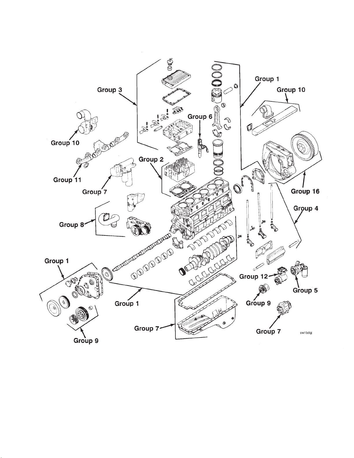
Cummins 22-Group System Exploded Diagram
Page 5

Section I - Introduction
N14 Page i-1
Section I - Introduction
Section Contents
Page
Engine Diagrams .............................................................................................................................................. i-13
Engine Identification ........................................................................................................................................ i-12
General Cleaning Instructions.......................................................................................................................... i-16
Glass or Plastic Bead Cleaning...................................................................................................................... i-16
Solvent and Acid Cleaning ............................................................................................................................. i-16
Steam Cleaning ............................................................................................................................................. i-16
General Repair Instructions ............................................................................................................................... i-3
General Safety Instructions ............................................................................................................................... i-4
Important Safety Notice.................................................................................................................................... i-4
Glossary Of Terms............................................................................................................................................ i-10
Illustrations......................................................................................................................................................... i-9
Manual Organization........................................................................................................................................... i-2
Group Contents................................................................................................................................................ i-2
Index ............................................................................................................................................................... i-2
Metric Information ............................................................................................................................................ i-2
Table of Contents............................................................................................................................................. i-2
Simbolos Usados En Este Manual .................................................................................................................... i-6
Symbole.............................................................................................................................................................. i-8
Symboles Utilises Dans Ce Manuel .................................................................................................................. i-7
Symbols Used in this Manual ........................................................................................................................... i-5
Page 6

Manual Organization Section I - Introduction
N14Page i-2
Manual Organization
All references to engine components in this manual are divided into 22 specific groups. The organization is
consistent with the service bulletins, service parts topics, and the parts catalogs for your convenience in updating
your copy of the shop manual.
Table of Contents
The Table of Contents in the front of the manual contains a quick page reference for each group number.
Group Contents
Each group contains the following information:
• A ‘‘Section Contents’’ page at the beginning of each group to quickly aid in locating the information desired.
• A Service Tools list with recommended tools needed to rebuild the components.
• General information to aid in rebuilding the component and an explanation of design change differences.
• Step-by-step rebuild instructions for disassembly, cleaning, inspection, and assembly of the component.
• Symbols which represent the action outlined in the instructions. The definitions of the symbols, listed in four
languages (English, Spanish, French, and German), appear on pages i-5 through i-8.
Index
An alphabetical index is in the back of the manual to aid in locating specific information.
Metric Information
Both metric and U.S. customary values are used in this manual. The metric value is listed first, followed by the
U.S. customary in brackets. An example is 60°C [140°F].
Page 7

Section I - Introduction General Repair Instructions
N14 Page i-3
General Repair Instructions
This engine incorporates the latest diesel technology; yet, it is designed to be repaired using normal repair
practices performed to quality standards.
• Cummins Engine Company, Inc. does not recommend or authorize any modifications or repairs to
engines or components except for those detailed in Cummins Service Information. In particular, unauthorized repair to safety-related components can cause personal injury. Below is a partial listing of
components classified as safety-related:
Air Compressor
Air Controls
Air Shutoff Assemblies
Balance Weights
Cooling Fan
Fan Hub Assembly
Fan Mounting Bracket(s)
Fan Mounting Capscrews
Fan Hub Spindle
Flywheel
Flywheel Crankshaft Adapter
Flywheel Mounting Capscrews
Fuel Shutoff Assemblies
Fuel Supply Tubes
Lifting Brackets
Throttle Controls
Turbocharger Compressor Casing
Turbocharger Oil Drain Line(s)
Turbocharger Oil Supply Line(s)
Turbocharger Turbine Casing
Vibration Damper Mounting Capscrews
• Follow All Safety Instructions Noted in the Procedures.
- Follow the manufacturer’s recommendations for cleaning solvents and other substances used during the
repair of the engine. Always use good safety practices with tools and equipment.
• Provide A Clean Environment and Follow the Cleaning Instructions Specified in the Procedures
- The engine and its components must be kept clean during any repair. Contamination of the engine and
components will cause premature wear.
• Perform the Inspections Specified in the Procedures.
- The inspections will result in a minimal number of parts requiring replacement. The cost of the rebuild
will be reduced more than the cost of the additional inspection time.
• Replace all Components or Assemblies Which are Damaged or Worn Beyond the Specifications
• Use Genuine Cummins New or ReConW Service Parts and Assemblies
- The assembly instructions have been written to reuse as many components and assemblies as possible.
When it is necessary to replace a component or assembly, the procedure is based on the use of new
Cummins or Cummins ReConW components. All of the repair services described in this manual are
available from all Cummins Distributors and most Dealer locations.
• Follow The Specified Disassembly and Assembly Procedures to Avoid Damage to the Components.
Complete troubleshooting and repair instructions are available in the Troubleshooting and Repair Manual which
can be ordered or purchased from a Cummins Authorized Repair Location. Refer to Section L, Literature, for
ordering instructions.
Page 8

General Safety Instructions Section I - Introduction
N14Page i-4
General Safety Instructions
Important Safety Notice
WARNING
Read and understand all of the safety precautions and warnings before performing any repair. This list contains
the general safety precautions that must be followed to provide personal safety. Special safety precautions are
included in the procedures when they apply.
• Make sure the work area surrounding the product is safe. Be aware of hazardous conditions that can exist.
• Always wear protective glasses and protective shoes when working.
•Donot wear loose-fitting or torn clothing. Remove all jewelry when working.
• Disconnect the battery and discharge any capacitors before beginning any repair work. Disconnect the air
starting motor if equipped to prevent accidental engine starting. Put a ″Do Not Operate″ tag in the operator’s
compartment or on the controls.
• Use ONLY the proper engine barring techniques for manually rotating the engine. Do not attempt to rotate
the engine by pulling or prying on the fan. This practice can cause serious personal injury, property damage,
or damage to the fan blade(s) causing premature fan failure.
• If an engine has been operating and the coolant is hot, allow the engine to cool before you slowly loosen the
filler cap and relieve the pressure from the cooling system.
•Donot work on anything that is supported ONLY by lifting jacks or a hoist. Always use blocks or proper stands
to support the product before performing any service work.
• Relieve all pressure in the air, oil, and the cooling systems before any lines, fittings, or related items are
removed or disconnected. Be alert for possible pressure when disconnecting any device from a system that
utilizes pressure. Do not check for pressure leaks with your hand. High pressure oil or fuel can cause personal
injury.
• To prevent suffocation and frostbite, wear protective clothing and ONLY disconnect liquid refrigerant (freon)
lines in a well ventilated area.
• To avoid personal injury, use a hoist or get assistance when lifting components that weigh 23 kg [50 lb] or
more. Make sure all lifting devices such as chains, hooks, or slings are in good condition and are of the correct
capacity. Make sure hooks are positioned correctly. Always use a spreader bar when necessary. The lifting
hooks must not be side-loaded.
• Cooling System corrosion inhibitor contains alkali. Do not get the substance in your eyes. Avoid prolonged
or repeated contact with skin. Do not swallow internally. In case of contact, immediately wash skin with soap
and water. Incase ofcontact, immediately flood eyes withlarge amountsof water fora minimumof 15 minutes.
IMMEDIATELY CALL A PHYSICIAN. KEEP OUT OF REACH OF CHILDREN.
• Naptha and Methyl Ethyl Ketone (MEK) are flammable materials and must be used with caution. Follow the
manufacturer’s instructions to provide complete safety when using these materials. KEEP OUT OF REACH
OF CHILDREN.
• To avoidburns, be alert for hotparts on products that havejust been turned OFF, and hot fluids in lines,tubes,
and compartments.
• Always use tools that are in good condition. Make sure you understand how to use them before performing
any service work. Use ONLY genuine Cummins or Cummins ReconW replacement parts.
• Always use the same fastener part number (or equivalent) when replacing fasteners. Do not use a fastener
of lessor quality if replacements are necessary.
Page 9
Section I - Introduction Symbols Used in this Manual
N14 Page i-5
Symbols Used in this Manual
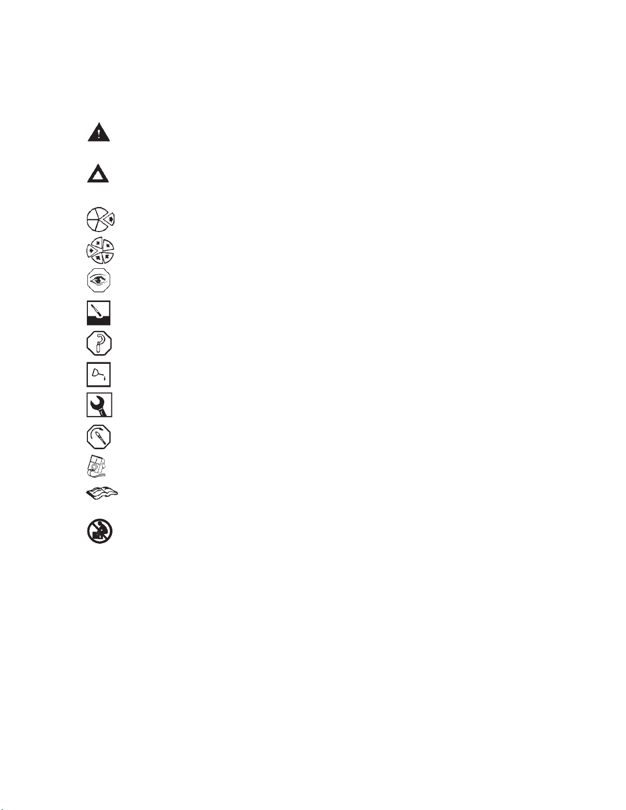
The following group of symbols has been used in this manual to help communicate the intent of the instructions.
When one of the symbols appears, it conveys the meaning defined below.
WARNING - Serious personal injury or extensive property damage can result if the warning
instructions are not followed.
CAUTION - Minor personal injury can result or a part, an assemblyor the engine canbe damaged
if the caution instructions are not followed.
Indicates a REMOVAL or DISASSEMBLY step.
Indicates an INSTALLATION or ASSEMBLY step.
INSPECTION is required.
CLEAN the part or assembly.
PERFORM a mechanical or time MEASUREMENT.
LUBRICATE the part or assembly.
Indicates that a WRENCH or TOOL SIZE will be given.
TIGHTEN to a specific torque.
PERFORM an electrical MEASUREMENT.
Refer to another location in this manual or another publication for additional information.
The component weighs 23 kg [50 lb] or more. To avoid personal injury, use a hoist or get
assistance to lift the component.
Page 10

Simbolos Usados En Este Manual Section I - Introduction
N14Page i-6
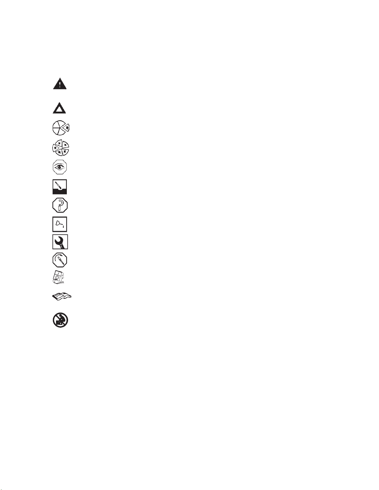
Simbolos Usados En Este Manual
Los si´mbolos siguientes son usados en este manual para clarificar el proceso de las instrucciones. Cuando
aparece uno de estos si´mbolos, su significado se especifica en la parte inferior.
ADVERTENCIA - Serios dan˜os personales o dan˜oa la propiedad puede resultar si las instrucciones
de Advertencia no se consideran.
PRECAUCION - Dan˜os menores pueden resultar, o de piezas del conjunto o el motor puede
averiarse si las instrucciones de Precaucio´n no se siguen.
Indica un paso de REMOCION o DESMONTAJE.
Indica un paso de INSTALACION o MONTAJE.
Se requiere INSPECCION.
LIMPIESE la pieza o el montaje.
EJECUTESE una MEDICION meca´nica o del tiempo.
LUBRIQUESE la pieza o el montaje.
Indica que se dara´ una LLAVE DE TUERCAS oelTAMANx O DE HERRAMIENTA.
APRIETESE hasta un par torsor especi´fico.
EJECUTESE una MEDICION ele´ctrica.
Para informacio´n adicional refie´rase a otro emplazamiento de este manual o a otra publicacio´n
anterior.
El componente pesa 23 kg [50lb] o mas. Para evitar dano corporal empleen unacabria u obtengan
ayuda para elevar el componente.
Page 11

Section I - Introduction Symboles Utilises Dans Ce Manuel
N14 Page i-7
Symboles Utilises Dans Ce Manuel
Les symboles suivants sont utilise´s dans ce manuel pour aider a` communiquer le but des instructions. Quand l’un
de ces symboles apparaiˆt,ile´voque le sens de´fini ci-dessous:
AVERTISSEMENT - De graves le´sions corporelles ou des dommages mate´riels conside´rables
peuvent survenir si les instructions donne´es sous les rubriques ″Avertissement″ ne sont pas
suivies.
ATTENTION - De petites le´sions corporelles peuvent survenir, ou bien une pie`ce, un ensemble
ou le moteur peuvent eˆtre endommage´s si les instructions donne´es sous les rubriques ″Attention″ ne sont pas suivies.
Indique une ope´ration de DEPOSE.
Indique une ope´ration de MONTAGE.
L’INSPECTION est ne´cessaire.
NETTOYER la pie`ce ou l’ensemble.
EFFECTUER une MESURE me´canique ou de temps.
GRAISSER la pie`ce ou l’ensemble.
Indique qu’une DIMENSION DE CLE ou D’OUTIL sera donne´e.
SERRER a` un couple spe´cifique.
EFFECTUER une MESURE e´lectrique.
Se reporter a` un autre endroit dans ce manuel ou a` une autre publication pour obtenir des
informations plus comple`tes.
Le composant pese 23 kg [50 lb] ou davantage. Pour eviter toute blessure, employer un appariel
de levage ou demander de l’aide pour le soulever.
Page 12
Symbole Section I - Introduction
N14Page i-8
Symbole
In diesem Handbuch werden die folgenden Symbole verwendet, die wesentliche Funktionen hervorheben. Die
Symbole haben folgende Bedeutung:
WARNUNG - Wird die Warnung nicht beachtet, dann besteht erho¨hte Unfall- und
Bescha¨digungsgefahr.
VORSICHT - Werden die Vorsichtsmassnahmen nicht beachtet, dann besteht Unfall- und
Bescha¨digungsgefahr.
AUSBAU bzw. ZERLEGEN.
EINBAU bzw. ZUSAMMENBAU.
INSPEKTION erforderlich.
Teil oder Baugruppe REINIGEN.
DIMENSION - oder ZEITMESSUNG.
Teil oder Baugruppe O} LEN.
WERKZEUGGRO} SSE wird angegeben.
ANZUG auf vorgeschriebenes Drehmoment erforderlich.
Elektrische MESSUNG DURCHFU} HREN.
Weitere Informationen an anderer Stelle bzw. in anderen Handbu¨chern.
Das teil weigt 23 kg [50 lb] oder mehr. Zur vermeidung von koerperverletzung winde benutzen
oder hilfe beim heben des teils in anspruch nehmen.
Page 13
Section I - Introduction Illustrations
N14 Page i-9
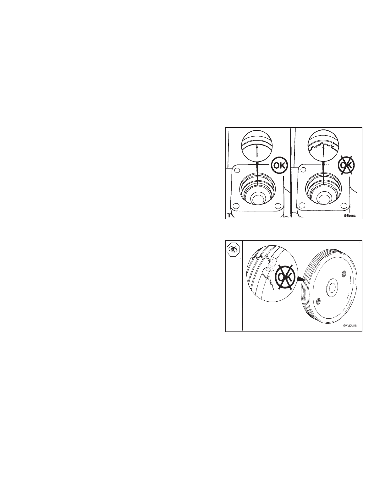
Illustrations
The illustrations used in this manual are intended to give an example of how to perform the action or the repair
being described. Many of the illustrations are common and will not look exactly like the engine or the parts used
in your application. Most of the illustrations contain symbols to indicate an action required or to indicate an
acceptable (OK) or unacceptable (not OK) condition.
Page 14

Glossary Of Terms Section I - Introduction
N14Page i-10
Glossary Of Terms
AFC: Air Fuel Control; a device in the PT fuel pump that limits the fuel delivery until
ATDC: After Top Dead Center; refers to the position of the piston or the crankshaft
BDC: Bottom Dead Center; refers to the position of the piston or the crankshaft rod
BTDC: Before Top Dead Center; refers to the position of the piston or the crankshaft
Circumferential Direction: In the direction of a circle in respect to the centerline of a round part or a
Concentricity: A measurement of the difference between the centers of either two or more
CPL: Control Parts List; this listing identifies the specific parts that must be in-
Cummins Sealant: This is a one part Room Temperature Vulcanizing (RTV) silicone rubber, adhe-
there is sufficient intake manifold pressure to allow for complete combustion.
rod journal. The piston is moving downward on the power stroke and intake
stroke.
journal. The piston is at its lowest position in the cylinder.
rod journal. The piston is moving upward on the compression stroke and exhaust stroke.
bore.
parts or the bores in one part.
stalled on the engine to meet agency certification.
sive and sealant material having high heat and oil resistance, and low compression set.
Some of the equivalent products are Marston Lubricants, Hylosil, Dow Corning, Silastic 732, Loctite Superflex, General Electric 1473, and General Electric 1470.
D.C.: Direct Current
Dye Penetrant Method: A method used to check for cracks in a part by using a dye penetrant and a
End Clearance: The clearance in an assembly determined by pushing the shaft in an axial di-
E.S.N.: Engine Serial Number
Hammer: A hand tool consisting of a hard steel head on a handle.
I.D.: Inside Diameter
Loctite 290: A single component, anaerobic, polyester resin, liquid sealant compound that
Loctite 609: A single component anaerobic, liquid adhesive that meets or exceeds the re-
Lubriplate 105: A mineral oil base grease with calcium soap (2 percent to 6 percent), and zinc
developer. Use crack detection kit, Part No. 3375432, or its equivalent.
rection one way and then pushing the shaft the other way.
hardens between closely fitted metal surfaces producing a tough, hard bond
with good characteristics. An equivalent product is Perma-Lok HL 126.
quirements of MIL-R-46082A (MR) TYPE 1.
Some of the equivalent products are Loctite 601 and Permabond HL 138.
oxide (2 percent to 4 percent) additives.
Page 15

Section I - Introduction Glossary Of Terms
N14 Page i-11
Magnetic Particle Inspection:
A method of checking for cracks in either steel or iron parts. This method requires a Magnaflux machine, or an equivalent machine that imparts a magnetic field on the part being checked.
Mallet: A hand tool consisting of a soft head, either wood, plastic, lead, brass, or
rawhide, on a handle.
MAX: Maximum allowed
MIN: Minimum allowed
No.: Number
O.D.: Outside Diameter
OS: Oversize
Protrusion: The difference in the height between two parts in the assembled state.
STD: Standard
TDC: Top Dead Center; refers to the position of the piston or the crankshaft rod
journal. The piston is at its highest position in the cylinder. The rod journal is
pointing straight up toward the piston.
T.I.R.: Total Indicator Runout; used when measuring the concentricity or the runout.
The T.I.R. refers to the total movement of the needle on a dial indicator, from
the most negative reading to the most positive reading.
Water Pump Grease: A premium high temperature grease that will lubricate antifriction bearings
continually from minus 40°C [minus 40°F] to plus 150°C [plus 350°F].
Some of the greases meeting this requirement are Aeroshell No. 5, Chevron
SRI, Amoco Rykon Premium No. 2, Texaco Premium RB, and Shell Dolium R.
Aeroshell No. 5 is not compatible with the other greases and must not be
mixed. Cummins Engine Company, Inc., uses Aeroshell No. 5 on new engines
and components.
Page 16
Engine Identification Section I - Introduction
N14Page i-12
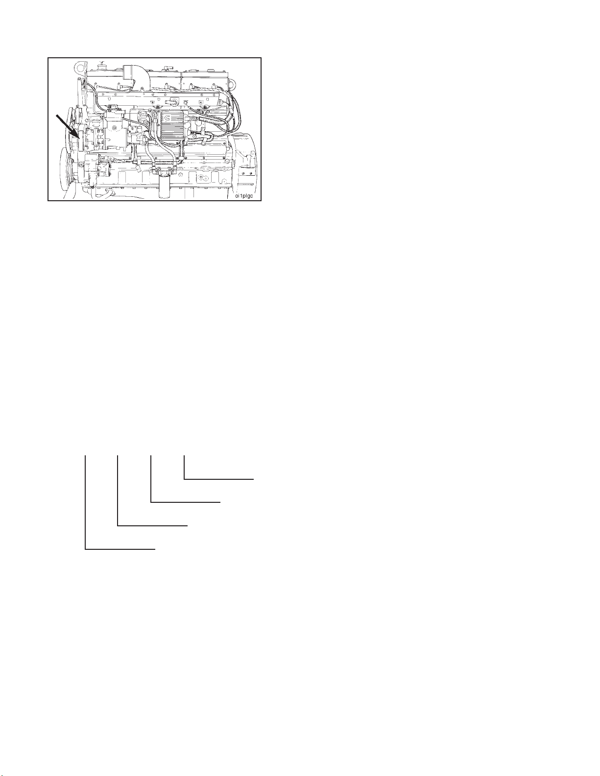
Engine Identification
The engine dataplate provides the model identification
and other important information about the engine.
Have the following engine data available when communicating with a Cummins Authorized Repair Location.
The information on the dataplate is mandatory when
sourcing service parts:
1. Engine Serial Number (E.S.N.)
2. Control Parts List (CPL)
3. Model
4. Advertised Horsepower and RPM
ap8plgi
The model name provides the following engine data:
N 14 330 E
CELECT™ Identification
Advertised Horsepower
Displacement (Liters)
Engine Model Designation
Page 17
Section I - Introduction Engine Diagrams
N14 Page i-13
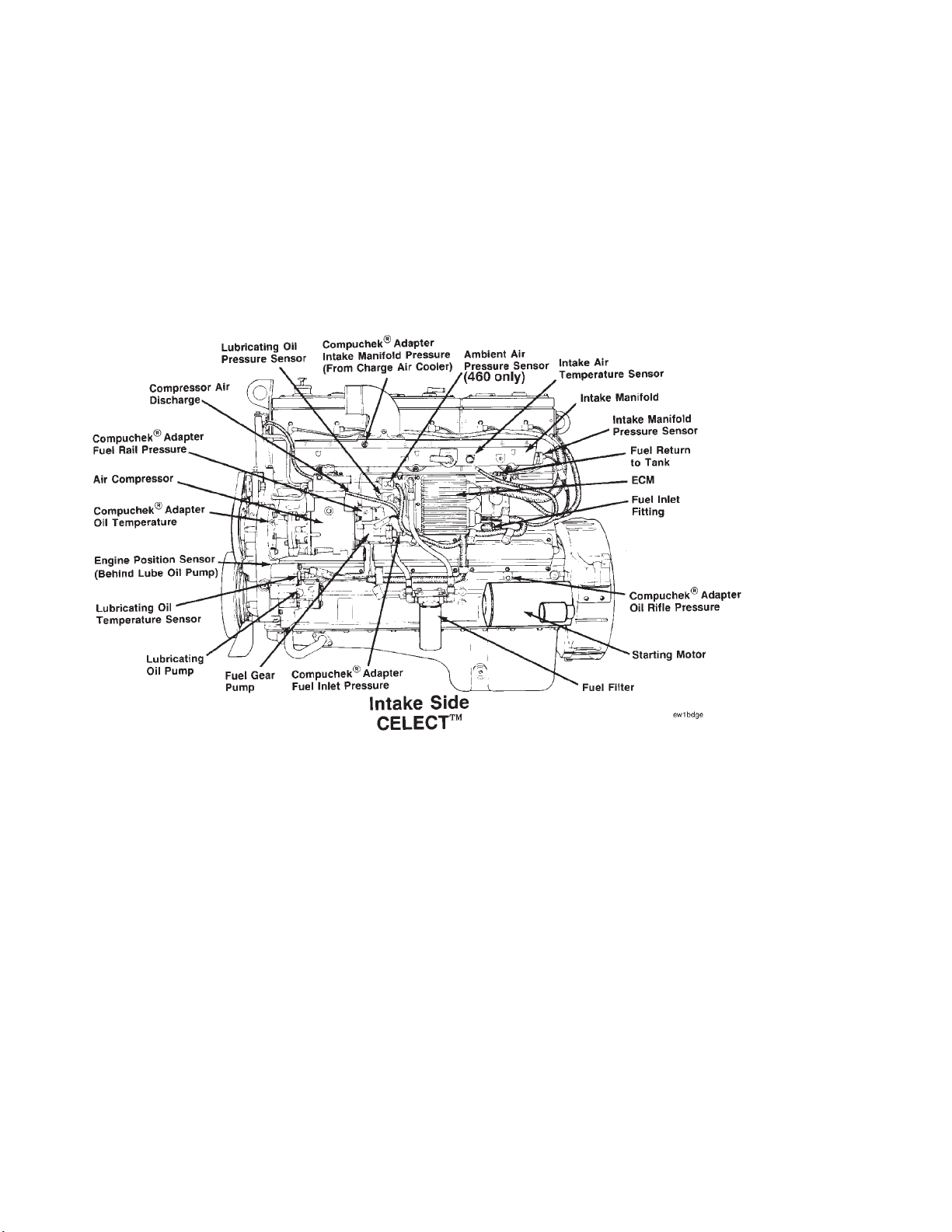
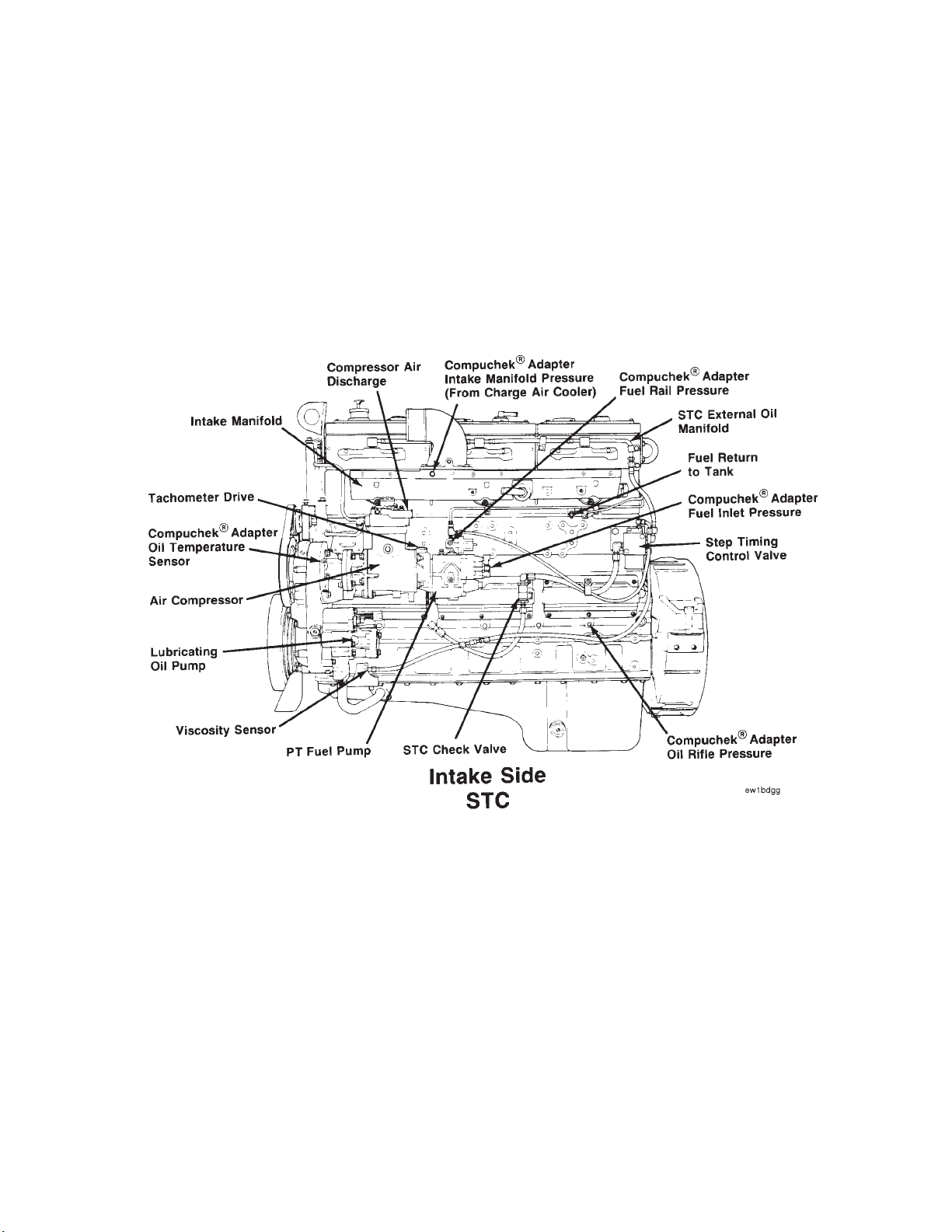
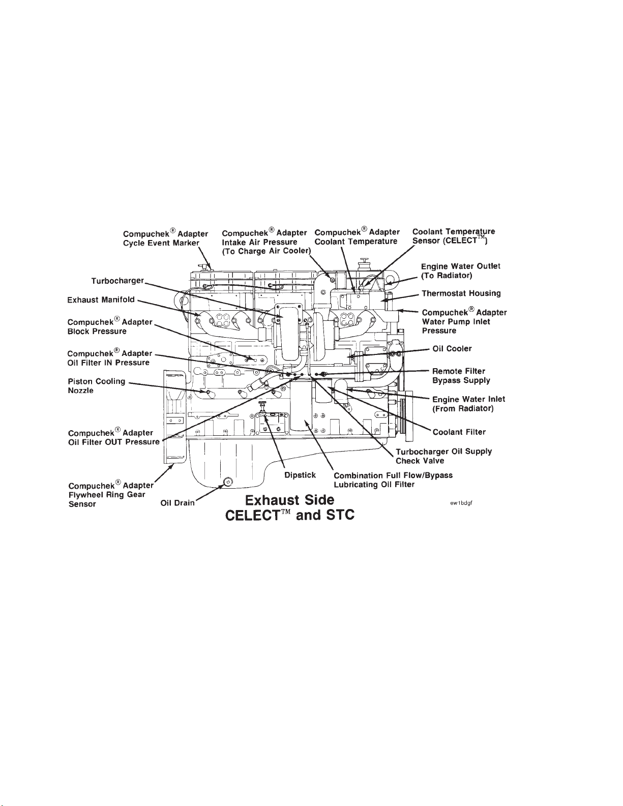
Engine Diagrams
The following drawings contain information about engine components, filter locations, drain points, and access
locations for instrumentation and engine controls.
The information and configuration of components shown in these drawings are of a general nature. Some
component locations will vary depending on applications and installations.
Page 18
Engine Diagrams Section I - Introduction
N14Page i-14
Page 19
Section I - Introduction Engine Diagrams
N14 Page i-15
Page 20

General Cleaning Instructions Section I - Introduction
N14Page i-16
General Cleaning Instructions
Solvent and Acid Cleaning
Several solvent and acid-type cleanerscan beused toclean the engine parts. Cummins Engine Company,
Inc. does not recommend any specific cleaners. Always follow the cleaner manufacturer’s instructions.
Experience has shown that the best results can be obtained using a cleaner that can be heated to 90 to
95 degrees Celsius [180 to 200 degrees Fahrenheit]. A cleaning tank that provides a constant mixing and
filtering of the cleaning solution will give the best results.
Remove all the gasket material, o-rings, and the depositsof sludge, carbon, etc., with a wire brush or scraper
before putting the parts in a cleaning tank. Be careful not to damage any gasket surfaces. When possible,
steam clean the parts before putting them in the cleaning tank.
Warning: The use of acid can be extremely dangerous to personnel, and can damage the machinery.
Always provide a tank of strong soda water as a neutralizing agent.
Rinse all of the parts in hot water after cleaning. Dry completely with compressed air. Blow the rinse water from
all of the capscrew holes and the oil drillings.
If the parts are not to be used immediately after cleaning, dip them in a suitable rustproofing compound. The
rustproofing compound must be removed from the parts before installation on the engine.
Steam Cleaning
Steam cleaning can be used to remove all types of dirt that can contaminate the cleaning tank. It is the
recommended way to clean the oil drillings.
Warning: Wear protective clothing to prevent personal injury from the high pressure and extreme heat.
Do not steam clean the following parts:
1. Electrical Components
2. Wiring
3. Injectors
4. Fuel Pump
5. Belts and Hoses
6. Bearings
Glass or Plastic Bead Cleaning
Glass or plastic bead cleaning can be used on many engine components to remove carbon deposits. The
cleaning process is controlled by the size of the glass or plastic beads, the operating pressure, and the
cleaning time.
Caution: Do not use glass or plastic bead cleaning on aluminum piston skirts. Do not use glass bead
cleaning on aluminum ring grooves. Small particles of glass or plastic will embed in the aluminum and
result in premature wear. Valves, turbocharger shafts, etc., can also be damaged. Follow the cleaning
directions listed in the procedures.
NOTE: Plastic bead blasting media, Part No. 3822735, can be used to clean aluminum ring grooves. Do not use
any bead blasting media on pin bores or aluminum skirts.
Follow the equipment manufacturer’s cleaning instructions. The following guidelines can be used to adapt to
manufacturer’s instructions:
1. Bead size: - Use U.S. size No. 16-20 forpiston cleaning with plastic bead media, Part No. 3822735.
- Use U.S. size No. 70 for piston domes with glass media.
- Use U.S. size No. 60 for general purpose cleaning with glass media.
2. Operating Pressure: - Glass: Use 620 kPa [90 psi] for general purpose cleaning.
- Plastic: Use 270 kPa [40 psi] for piston cleaning.
3. Steam clean or wash the parts with solvent to remove all of the foreign material and glass or plastic
beads after cleaning. Rinse with hot water. Dry with compressed air.
4. Do not contaminate the wash tanks with glass or plastic beads.
Page 21

Engine Disassembly and Assembly
N14 Page 0-1
Section 0 - Engine Disassembly and Assembly - Group 00
Section Contents
Page
Accessory Drive - Installation ........................................................................................................................ 0-89
Accessory Drive - Removal ............................................................................................................................ 0-31
Accessory Drive Pulley - Installation .............................................................................................................. 0-97
Accessory Drive Pulley - Removal ................................................................................................................. 0-23
Accessory Drive Seal - Installation ................................................................................................................ 0-96
Accessory Drive Seal - Removal..................................................................................................................... 0-39
Air Compressor - Installation ........................................................................................................................ 0-124
Air Compressor - Removal .............................................................................................................................. 0-30
Air Compressor Coolant Inlet and Outlet Tubes - Installation ..................................................................... 0-135
Air Compressor Coolant Inlet and Outlet Tubes - Removal .......................................................................... 0-22
Alternator - Installation.................................................................................................................................. 0-142
Alternator - Removal ...................................................................................................................................... 0-14
Alternator Belts - Installation and Adjustment ............................................................................................. 0-142
Alternator Belts - Removal ............................................................................................................................. 0-13
Alternator Mounting Bracket - Installation.................................................................................................... 0-142
Alternator Mounting Bracket - Removal ........................................................................................................ 0-14
Cam Follower Assemblies - Installation ........................................................................................................ 0-80
Cam Follower Assemblies - Removal ............................................................................................................ 0-38
Camshaft - Installation ................................................................................................................................... 0-78
Camshaft - Removal ....................................................................................................................................... 0-39
Camshaft Bearing Support - Installation ....................................................................................................... 0-94
Camshaft Bearing Support - Removal ........................................................................................................... 0-38
CELECT™ Actuator Harness - Installation ..................................................................................................... 0-128
CELECT™ Actuator Harness - Removal .......................................................................................................... 0-25
CELECT™ Ambient Air Pressure Sensor - Installation.................................................................................. 0-126
CELECT™ Ambient Air Pressure Sensor - Removal ...................................................................................... 0-28
CELECT™ Boost Pressure Sensor - Installation............................................................................................ 0-121
CELECT™ Boost Pressure Sensor - Removal ................................................................................................ 0-33
CELECT™ Coolant Temperature Sensor - Installation .................................................................................. 0-135
CELECT™ Coolant Temperature Sensor - Removal ....................................................................................... 0-21
CELECT™ ECM Cooling Plate - Installation ................................................................................................... 0-125
CELECT™ ECM Cooling Plate - Removal ........................................................................................................ 0-29
CELECT™ Electronic Control Module (ECM) - Installation ............................................................................ 0-126
CELECT™ Electronic Control Module (ECM) - Removal ................................................................................. 0-28
CELECT™ Engine Position Sensor (EPS) - Installation................................................................................... 0-91
CELECT™ Engine Position Sensor (EPS) - Removal ...................................................................................... 0-31
CELECT™ Intake Air Temperature Sensor - Installation ............................................................................... 0-121
CELECT™ Intake Air Temperature Sensor - Removal .................................................................................... 0-33
CELECT™ Lubricating Oil Pressure Sensor - Installation ............................................................................. 0-126
Page 22

Engine Disassembly and Assembly
N14Page 0-2
Page
CELECT™ Lubricating Oil Pressure Sensor - Removal .................................................................................. 0-29
CELECT™ Sensor Harness - Installation........................................................................................................ 0-127
CELECT™ Sensor Harness - Removal ............................................................................................................ 0-27
Coolant - Drainage........................................................................................................................................... 0-11
Coolant Filter - Installation............................................................................................................................ 0-147
Coolant Filter - Removal ................................................................................................................................ 0-11
Coolant Inlet Transfer Connection - Installation........................................................................................... 0-140
Coolant Inlet Transfer Connection - Removal ............................................................................................... 0-15
Crankcase Breather - Removal ...................................................................................................................... 0-12
Crankcase Breather Tube - Installation ........................................................................................................ 0-147
Crankshaft - Installation ................................................................................................................................. 0-48
Crankshaft - Removal ..................................................................................................................................... 0-44
Crankshaft Seal, Front - Installation .............................................................................................................. 0-94
Crankshaft Seal, Front - Removal ................................................................................................................... 0-39
Crankshaft Seal, Rear - Installation ............................................................................................................... 0-66
Crankshaft Seal, Rear - Removal ................................................................................................................... 0-20
Cylinder Block - Installation on the Rebuild Stand ....................................................................................... 0-46
Cylinder Block - Removal from the Rebuild Stand ........................................................................................ 0-46
Cylinder Heads - Installation .......................................................................................................................... 0-76
Cylinder Heads - Removal .............................................................................................................................. 0-37
Cylinder Liners - Installation .......................................................................................................................... 0-57
Cylinder Liners - Removal .............................................................................................................................. 0-42
Dipstick Tube and Housing - Installation...................................................................................................... 0-140
Dipstick Tube and Housing - Removal .......................................................................................................... 0-15
Engine - Cleaning ........................................................................................................................................... 0-10
Engine - Covering All Openings.................................................................................................................... 0-148
Engine - Installation on the Rebuild Stand .................................................................................................... 0-16
Engine - Preparation for Cleaning................................................................................................................... 0-10
Engine - Removal From the Rebuild Stand................................................................................................... 0-138
Engine Brake - Adjustment ........................................................................................................................... 0-115
C-Brake....................................................................................................................................................... 0-115
C-Brake - Alternate Method ......................................................................................................................... 0-118
Jacobs Brake .............................................................................................................................................. 0-119
Engine Brake - Installation ............................................................................................................................ 0-115
Engine Brakes - Removal ............................................................................................................................... 0-34
Engine Disassembly and Assembly - General information .............................................................................. 0-9
Assembly ........................................................................................................................................................ 0-9
Disassembly ................................................................................................................................................... 0-9
Engine Disassembly and Assembly - Service Tools ........................................................................................ 0-5
Engine Support Bracket, Front - Installation ................................................................................................ 0-131
Engine Support Bracket, Front - Removal ..................................................................................................... 0-23
Exhaust Manifold - Installation...................................................................................................................... 0-144
Exhaust Manifold - Removal ........................................................................................................................... 0-13
Fan and Fan Spacer - Installation ................................................................................................................. 0-143
Page 23

Engine Disassembly and Assembly
N14 Page 0-3
Page
Fan and Fan Spacer - Removal ...................................................................................................................... 0-13
Fan Belts - Installation and Adjustment........................................................................................................ 0-137
Fan Belts - Removal ....................................................................................................................................... 0-20
Fan Hub and Fan Hub Support Bracket - Installation................................................................................... 0-136
Fan Hub and Fan Hub Support Bracket - Removal ....................................................................................... 0-21
Flywheel - Installation .................................................................................................................................... 0-72
Bore Alignment - Measurement .................................................................................................................... 0-73
Face Alignment - Measurement .................................................................................................................... 0-75
Flywheel - Removal ........................................................................................................................................ 0-18
Flywheel Housing - Installation ...................................................................................................................... 0-67
Bore Alignment - Measurement .................................................................................................................... 0-68
Face Alignment - Measurement .................................................................................................................... 0-70
Flywheel Housing - Removal ......................................................................................................................... 0-19
Fuel Crossovers - Installation ........................................................................................................................ 0-98
Fuel Crossovers - Removal ............................................................................................................................ 0-37
Fuel Pump - Installation ................................................................................................................................ 0-124
CELECT™ Engines ...................................................................................................................................... 0-124
STC Engines............................................................................................................................................... 0-125
Fuel Pump - Removal ..................................................................................................................................... 0-29
CELECT™ Engines ....................................................................................................................................... 0-29
STC Engines ................................................................................................................................................ 0-30
Fuel Tubing - Installation .............................................................................................................................. 0-123
Fuel Tubing - Removal ................................................................................................................................... 0-31
Gear Cover - Installation ................................................................................................................................ 0-92
Gear Cover - Removal .................................................................................................................................... 0-39
Injection Timing - General Information .......................................................................................................... 0-80
Timing Tool Installation ................................................................................................................................ 0-82
Injector and Valve Adjustment...................................................................................................................... 0-105
CELECT™ Engines ...................................................................................................................................... 0-105
STC Engines............................................................................................................................................... 0-109
Injectors - Installation ................................................................................................................................... 0-100
CELECT™ Engines ..................................................................................................................................... 0-100
STC Engines............................................................................................................................................... 0-101
Injectors - Removal ........................................................................................................................................ 0-35
CELECT™ Engines ....................................................................................................................................... 0-35
STC Engines ................................................................................................................................................ 0-36
Intake Manifold - Installation......................................................................................................................... 0-120
Intake Manifold - Removal ............................................................................................................................. 0-33
Lubricating Oil Cooler Assembly - Installation ............................................................................................. 0-141
Lubricating Oil Cooler Assembly - Removal .................................................................................................. 0-14
Lubricating Oil Filter - Installation ................................................................................................................ 0-147
Lubricating Oil Filter - Removal ..................................................................................................................... 0-11
Lubricating Oil Pan - Installation ................................................................................................................... 0-98
Lubricating Oil Pan - Removal ....................................................................................................................... 0-39
Lubricating Oil Pump - Installation ................................................................................................................ 0-91
Lubricating Oil Pump - Removal ..................................................................................................................... 0-32
Lubricating Oil Pump Signal Line - Installation ............................................................................................ 0-122
Lubricating Oil Pump Signal Line - Removal.................................................................................................. 0-32
Page 24

Engine Disassembly and Assembly
N14Page 0-4
Page
Lubricating Oil Transfer Tube - Installation.................................................................................................. 0-122
Lubricating Oil Transfer Tube - Removal ...................................................................................................... 0-31
Piston and Connecting Rod Assemblies - Assembly and Installation .......................................................... 0-61
Piston and Connecting Rod Assemblies - Removal ....................................................................................... 0-40
Piston Cooling Nozzles - Installation ............................................................................................................ 0-139
Piston Cooling Nozzles - Removal ................................................................................................................. 0-15
Push Tubes - Installation ............................................................................................................................. 0-102
Push Tubes - Removal ................................................................................................................................... 0-35
Rear Cover - Installation ................................................................................................................................ 0-65
Rear Cover - Removal .................................................................................................................................... 0-20
Rocker Housing Covers - Installation ........................................................................................................... 0-119
Rocker Housing Covers - Removal ................................................................................................................ 0-34
Rocker Lever Housing - Installation .............................................................................................................. 0-98
Rocker Lever Housing - Removal .................................................................................................................. 0-36
Rocker Lever Shaft Assemblies - Installation .............................................................................................. 0-104
Rocker Lever Shaft Assemblies - Removal ................................................................................................... 0-34
Starting Motor - Installation .......................................................................................................................... 0-144
Starting Motor - Removal ............................................................................................................................... 0-13
STC External Oil Plumbing - Installation ...................................................................................................... 0-130
STC External Oil Plumbing - Removal ........................................................................................................... 0-24
STC Oil Control Valve - Installation .............................................................................................................. 0-129
STC Oil Control Valve - Removal ................................................................................................................... 0-25
Thermostat Housing - Installation................................................................................................................. 0-135
Thermostat Housing - Removal ..................................................................................................................... 0-22
Turbocharger - Installation............................................................................................................................ 0-145
Turbocharger - Removal ................................................................................................................................ 0-12
Valve Crossheads - Installation .................................................................................................................... 0-103
Valve Crossheads - Removal ......................................................................................................................... 0-35
Vibration Damper - Installation ..................................................................................................................... 0-131
Vibration Damper - Removal .......................................................................................................................... 0-23
Viscosity Sensor - Installation ...................................................................................................................... 0-121
Viscosity Sensor - Removal ........................................................................................................................... 0-32
Water Header Covers - Installation ............................................................................................................... 0-140
Water Header Covers - Removal .................................................................................................................... 0-16
Water Pump - Installation.............................................................................................................................. 0-133
Water Pump - Removal .................................................................................................................................. 0-23
Water Pump Belt - Installation and Adjustment ........................................................................................... 0-134
Water Pump Belt - Removal ........................................................................................................................... 0-21
Page 25
Engine Disassembly and Assembly Engine Disassembly and Assembly - Service Tools
N14 Page 0-5
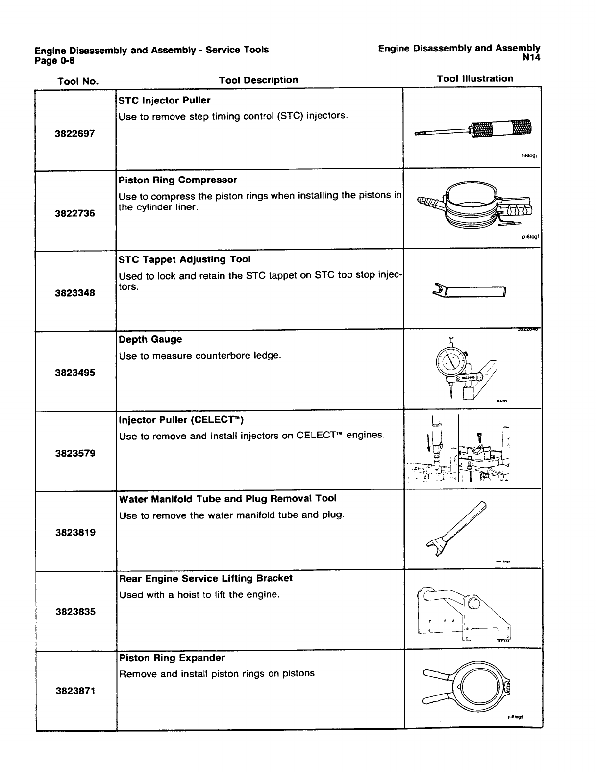
Engine Disassembly and Assembly - Service Tools
The following special tools are recommended to perform procedures in section 1. The use of these
toolsis shown in the appropriate procedure.These tools can bepurchased from your local Cummins
Authorized Repair Location.
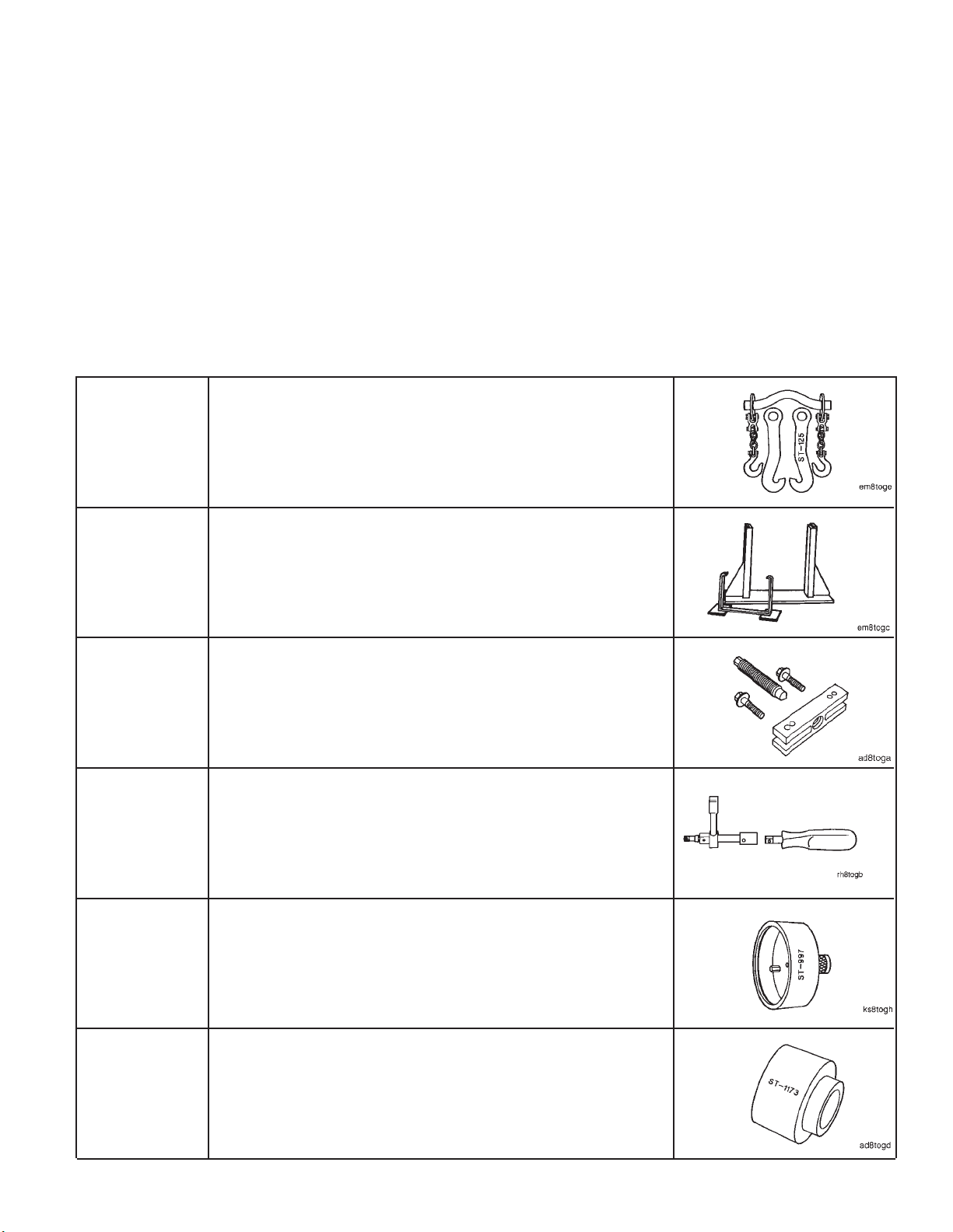
Tool No. Tool Description Tool Illustration
Lifting Fixture
Designed to lift all H/NH engines except 5 1/8-inch bore with a
ST-125 or
3822512
top mounted turbocharger.
ST-163
ST-647
ST-669
ST-997
Engine Support Stand
Support engine when not in-chassis or on the engine rebuild
stand.
Standard Puller
Use to remove drive pulleys, impellers, etc.
Torque Wrench Adapter
Tighten crosshead and rocker lever adjusting screws.
Crankshaft Oil Seal Installer
Use to drive the crankshaft oil seal into the rear cover. This tool
also aligns the rear cover to the crankshaft.
ST-1173
Fuel Pump Drive Oil Seal Mandrel
Use to drive the accessorydrive oil sealinto the gear cover while
mounted.
Page 26
Engine Disassembly and Assembly - Service Tools Engine Disassembly and Assembly
N14Page 0-6
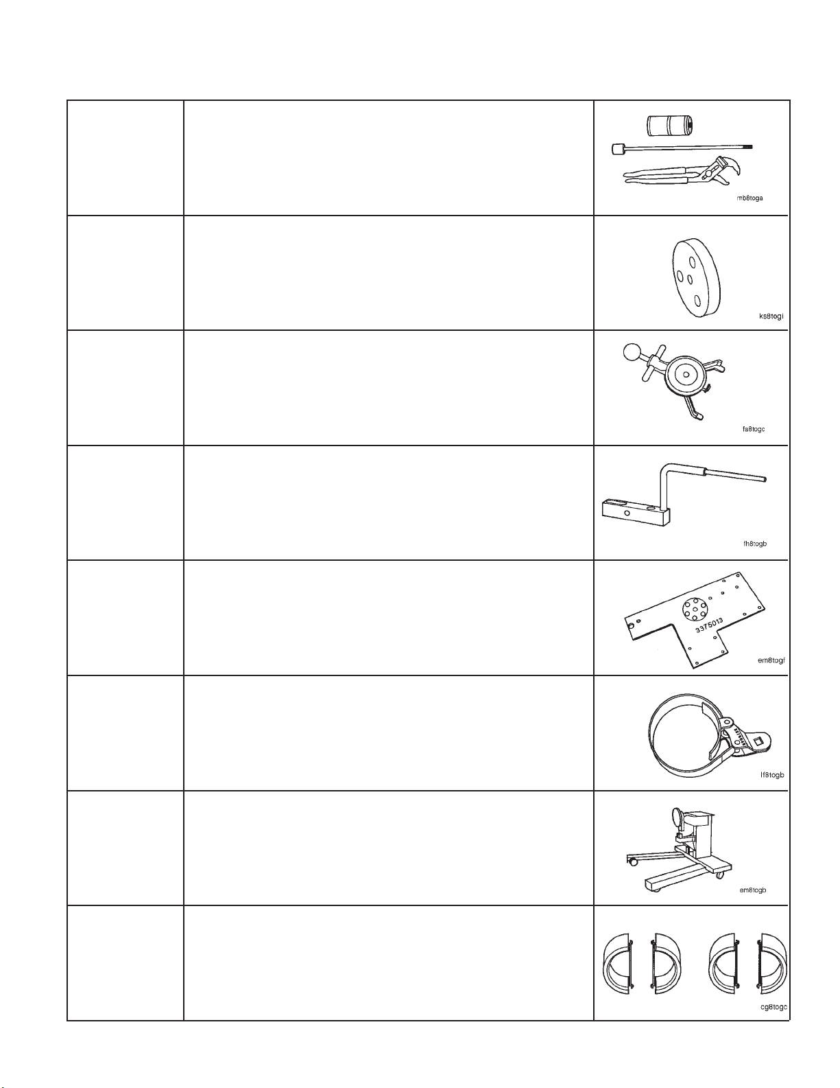
Tool No. Tool Description Tool Illustration
Main Bearing Cap Puller
Remove main bearings caps.
ST-1178
Top Plate
Included in oil seal puller/installer, Part No. ST-1259. Use to pull
ST-1259-1
or install the front crankshaft oil seal.
Belt Tension Gauge
Measure drive belt tension.
ST-1293
ST-1325
3375013
3375049
3375194
Dial Gauge Attachment
Attaches to crankshaft to provide measuring of flywheel housing
runout with a dial indicator.
Adapter Plate
Use the adapter plate to mount the engine to engine rebuild
stand, Part No. 3375194.
Oil Filter Wrench
Use to remove or tighten spin-on lubricating oil filters.
Engine Rebuild Stand
Support cylinder block during engine rebuild. Use with adapter
plate, Part No. 3375013.
3375268
Camshaft Installation Pilots
Use to guide the camshaft though the block camshaft bushings.
Four are required per operation.
Page 27
Engine Disassembly and Assembly Engine Disassembly and Assembly - Service Tools
N14 Page 0-7
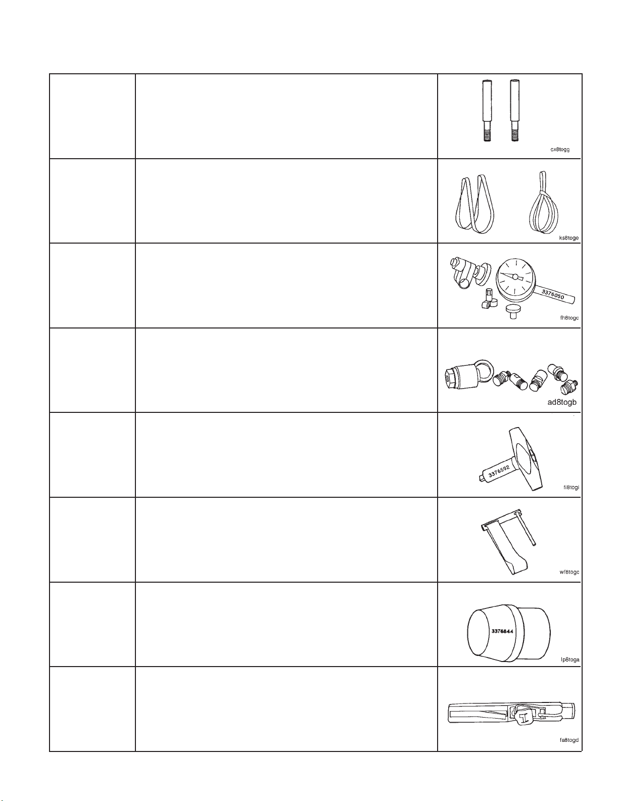
Tool No. Tool Description Tool Illustration
Connecting Rod Guide Pins
Guide connecting rods over crankshaft during removal or in-
3375601
stallation of connecting rods.
Nylon Lifting Sling
Aid in removal andinstallation of crankshaft, flywheel, and other
3375957
heavy components.
Dial Indicator and Sleeve Assembly
Use with dial gauge attachment, Part No. ST-1325, to measure
3376050
flywheel and flywheel housing runout.
3376326
3376592
3376807
3376844
Pulley Installation Tool
Install drive pulleys.
Inch Pound Torque Wrench
Required to make consistent settings of the top stop injectors.
Screwdriver socket, Part No. ST-669-13, must be used with this
tool.
Water and Fuel Filter Wrench
Use to remove the coolant filter and the fuel filter.
Lubrication Suction Tube O-ring Expander
Use to install the lubricating oil transfer tube.
3822524
Belt Tension Gauge
Use to check the belt tension on 3/8-inch to 1/2-inch top width
belts.
Page 28
Page 29

Engine Disassembly and Assembly Engine Disassembly and Assembly - General information
N14 Page 0-9
Engine Disassembly and Assembly - General information
These procedures apply to all N14 engines. The differences between engine models due to the application, the
optional equipment on an engine, and the year an engine was built are included in the instructions. Omit the steps
that do not apply to the engine being rebuilt.
1. A warning statement is included for any component or assembly that weighs more than 23 kg [50 lb]. To avoid
personal injury, use a hoist or get assistance from more than one person when removing or installing these
parts.
2. All capscrews used on the N14 engine are U.S. customary.
Disassembly
The instructions in this procedure are organized in a logical sequence to disassemble an engine. This is not the
only sequence to disassemble an engine. Certain parts must be removed in the sequence indicated. Use this
sequence until you become familiar with the engine.
Discard all gaskets (except rocker housing cover gaskets which are reusable), seals, hoses, filters, and o-rings.
Keep these parts if they are needed for a failure analysis.
Label, tag, or mark the parts for location as the parts are removed in order to easily find all of the parts that can
be involved in a failure and to simplify the assembly procedure.
Label, tag, mark or photograph all special equipment prior to the removal from an engine. This engine assembly
procedure does not include the installation of special optional equipment.
Force must be used to remove certain parts. A mallet must be used when force is required. All of the fasteners
must be removed before using force.
Avoid as much dirt as possible during disassembly. The accumulation of additional dirt will make it more difficult
to clean the components.
Assembly
Make sure all thecomponents andassemblies havebeen cleaned,replaced or rebuilt, and areready tobe installed
on the engine before beginning the assembly process.
Torque values arelisted ineach step. If a torquevalue isnot specified, usethe chartlisted in Specifications,Group
18, to determine the correct torque value.
Many of the gaskets and the o-rings are manufactured from a material designed to absorb oil. These gaskets will
enlarge and provide a tight seal after coming in contact with oil. Use ONLY a recommended contact adhesive or
a vegetable-based oil to install these parts.
Always use a capscrew of the samesystem (metric or U.S. customary), the same dimension, and the same grade
as the capscrew removed. The use of a longer, shorter, different grade, or wrong thread capscrew than the
capscrew that is listed can result in damage to the engine.
Page 30
Engine - Preparation for Cleaning Engine Disassembly (00-01)
N14Page 0-10
Engine Disassembly (00-01)
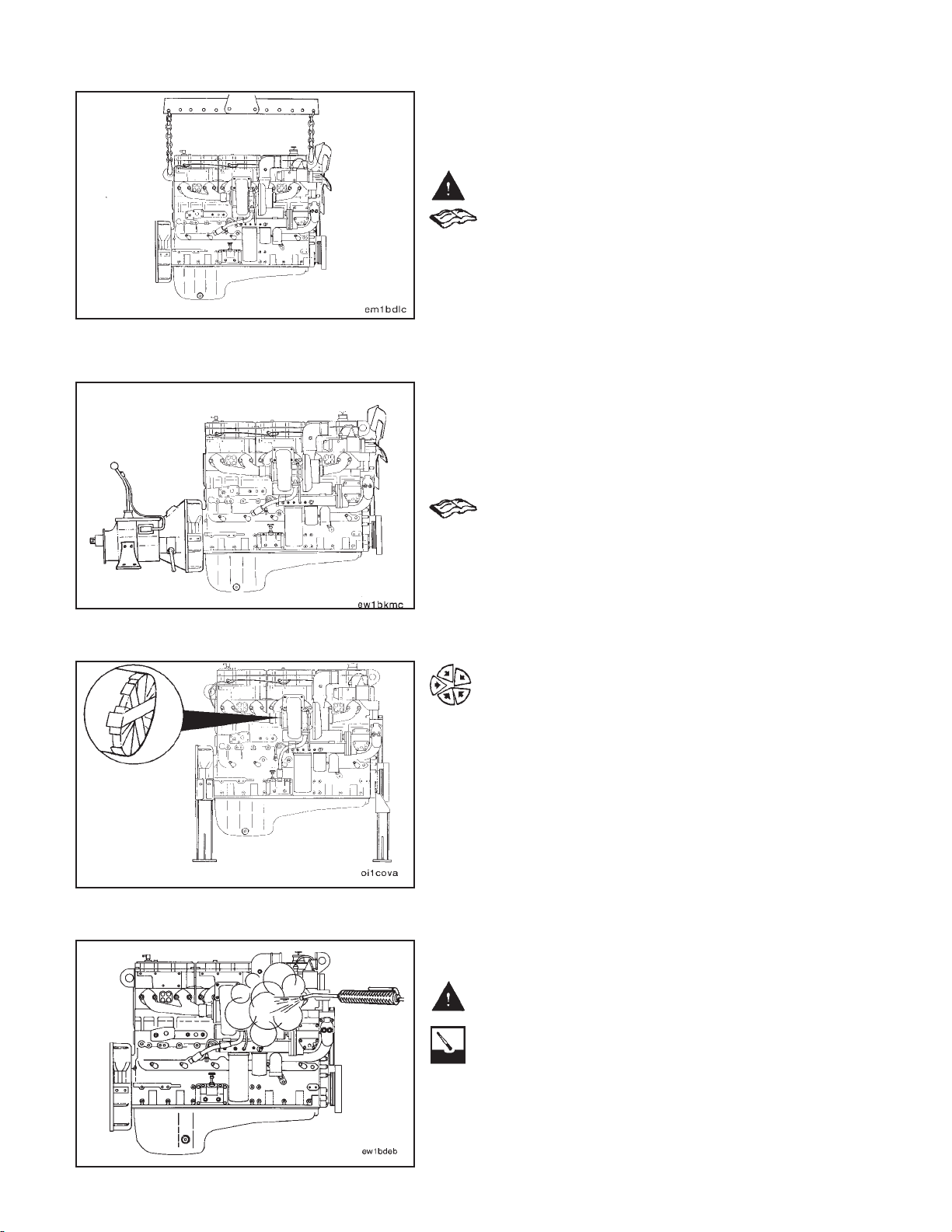
Engine - Preparation for Cleaning
Warning: The engine lifting equipment must be designed
to safely lift the engine and the transmission as an assembly. The dry weight of the standard engine with
accessories is 1256 kg [2770 lbs]. Refer to the equipment
manufacturer’s specifications for the transmission
weight.
Use a correctly rated hoist, and attach engine lifting fixture, Part No. ST-125 or Part No. 3822512, to the engine
mounted lifting brackets to remove the engine.
NOTE: If the transmission is not removed, place a support
under the transmission to prevent it from falling.
Installations such as short and medium nose conventional chassis, the factory installed rear engine lifting
brackets are usually removed due to space constraints.
In this case, the service rear engine lifting bracket, Part
No. 3823835, will be required to remove the engine from
the chassis.
Refer to the N14 Troubleshooting and Repair Manual,
Bulletin No. 3810456, Section 9, for further information.
Install the engine on two engine support stands, Part No.
ST-163.
Label and remove all electrical wiring and controls.
Install caps or tape on the following openings to prevent
moisture and dirt from entering the engine:
1. Both sides of the turbocharger.
2. All oil, air, water, and fuel openings.
Engine - Cleaning
Warning: When using a steam cleaner, wear protective
clothing and safety glasses or a face shield. Hot steam
can cause serious personal injury.
Use steam to clean the engine, and dry with compressed
air.
Page 31

Engine Disassembly (00-01) Coolant - Drainage
N14 Page 0-11
NOTE: The maximum oil pan capacity is 34 liters [9.0 U.S.
gallons].
Remove the drain plugand the copper washer. Check the
copper washer for wear.
Drain the oil.
If the drain plug is installed again, tighten the plug to the
specified torque.
Torque Value: 136 N•m [100 ft-lb]
Coolant - Drainage
Remove the plugs from the engine and open the cylinder
block draincock and the oil cooler draincock.
Use a suitable container to catch the coolant as it is
drained.
Coolant Filter - Removal
Use a water and fuel filter wrench, Part No. 3376807, to
remove the coolant filter.
Lubricating Oil Filter - Removal
Use an oil filter wrench, Part No. 3375049, to remove the
lubricating oil filter.
Page 32

Crankcase Breather - Removal Engine Disassembly (00-01)
N14Page 0-12
Crankcase Breather - Removal
Loosen the hose clamp at the breather vent tube.
Remove the tube support bracket capscrew and the
bracket.
Remove the tube and the hose from the engine.
Turbocharger - Removal
Remove the oil supply and the oil drain tubes from the
turbocharger.
Remove the four turbocharger mounting nuts.
Remove the turbocharger and discard the gasket.
NOTE: If the turbocharger mounting nuts do not loosen
freely, split the nuts to avoid breaking a mounting stud.
Loosen the clamp on the discharge elbow.
Remove the elbow and discard the o-ring.
Page 33

Engine Disassembly (00-01) Exhaust Manifold - Removal
N14 Page 0-13
Exhaust Manifold - Removal
NOTE: Two dowels are used in each cylinder head to align
the exhaust manifold assembly.
Remove two capscrews, and install two guide studs.
Warning: Because this assembly weighs more than 23
kg [50 lbs], two people or a hoist will be required to lift
the exhaust manifold assembly to avoid personal injury.
Remove the remaining ten capscrews, the exhaust manifold assembly, and the manifold gaskets.
Starting Motor - Removal
Warning: Because this part weighs more than 23 kg [50
lbs], two people or a hoist will be required to lift the
starting motor to avoid personal injury.
Remove the three starting motor capscrews, the starting
motor, and the spacer (if used).
Fan and Fan Spacer - Removal
Caution: A fan hub spacer can be behind the fan. It will
drop as the fan is removed. Make sure to remove the fan
and the fan hub spacer together.
Remove the six capscrews and the fan.
NOTE: Do not discard the fan spacers. The spacersprovide
the thickness needed to install the fan in the correct position.
Alternator Belts - Removal
Loosen the alternator to alternator support nut and capscrew.
Loosen the adjusting link capscrew and tensioning bolt,
if applicable.
Push the alternator toward the engine to release tension
on the alternator belt, and remove the belt(s).
Page 34

Alternator - Removal Engine Disassembly (00-01)
N14Page 0-14
Alternator - Removal
Remove the adjusting link capscrew and the adjusting
link.
Remove the alternator to alternator support bracket, nut,
washer, capscrew, and the alternator.
Alternator Mounting Bracket - Removal
Remove the three alternator mounting bracket capscrews
and the mounting bracket.
Lubricating Oil Cooler Assembly Removal
Remove the capscrew which holds the oil cooler support
bracket to the cylinder block at the rear of the oil cooler.
Remove one of the capscrews which holds the oil cooler
support to the cylinder block. Install a guide stud in the
hole.
Page 35

Engine Disassembly (00-01) Coolant Inlet Transfer Connection - Removal
N14 Page 0-15
Warning: Because this part weighs more than 23 kg [50
lbs], two people or a hoist will be required to lift the oil
cooler assembly to avoid personal injury.
Remove the remaining five capscrews from the oil cooler
support, and remove the cooler assembly.
Coolant Inlet Transfer Connection Removal
Loosen four mounting capscrews, and remove the coolant inlet transfer connection from the water pump.
Dipstick Tube and Housing - Removal
Remove the four capscrews and the housing.
Piston Cooling Nozzles - Removal
Remove the piston cooling nozzles. Locking pliers
clamped to the piston cooling nozzle flange may be
needed to prevent nozzle damage during removal.
Remove and discard the o-rings.
Page 36

Water Header Covers - Removal Engine Disassembly (00-01)
N14Page 0-16
Water Header Covers - Removal
Remove the six capscrews from each of the two water
header covers.
Remove the covers, and discard the gaskets.
Engine - Installation on the Rebuild Stand
NOTE: Use enginerebuild stand,Part No.3375194, and the
adapter plate, Part No. 3375013.
Use six 5/8-11 X 1 3/4-inch grade 5 capscrews to install
the adapter plate to the rebuild stand.
Torque Value: 102 N•m [75 ft-lb]
The engine stand adapter plate attaches to the cylinder
block at the capscrew locations shown.
Check the condition of the threads in the cylinder block
before attempting to mount the engine on the engine
stand.
Clean the threads in the cylinder block, and repair any
damaged threads.
Page 37

Engine Disassembly (00-01) Engine - Installation on the Rebuild Stand
N14 Page 0-17
Install the mounting plate adapter on the rear water
header.
Use five 1/4-20 X 1 1/4-inch capscrews to mount the
adapter. Tighten the capscrews.
Torque Value: 10 N•m [7 ft-lb]
Install three 1/2-13 X 3 3/8-inch capscrews through the
adapter plate as shown.
Install the three adapter plate spacers over the capscrews.
Use a lifting fixture, Part No. ST-125 or3822512, to lift the
engine.
Align the exhaust side of the engine to the adapter plate
of the rebuild stand.
Installation such as short andmedium nose conventional
chassis, the factory installed rear engine lifting brackets
are usually removed dueto spacecontraints. Inthis case,
the portable rear engine lifting bracket, Part No. 3823835,
will be required to install the engine onto the rebuild
stand.
Align the mounting hole in the adapter plate (1) with the
capscrew hole (2) in the mounting plate adapter.
Use a 5/8-11 X 1 3/4-inch grade 5 capscrew to mount the
adapter plate to the mounting plate adapter. Use your
fingers to tighten the capscrew.
Page 38

Flywheel - Removal Engine Disassembly (00-01)
Adjust the position of the engine so that the remaining
mounting holes in the adapter plate (1) and (2) align with
the capscrew holes in the cylinder block.
Use your fingers to tighten the three 1/2-13 X 3 3/8-inch
capscrews (1).
Install four 3/8-16 X 3 3/8-inch capscrews in the location
shown (2). Use your fingers to tighten the capscrews.
N14Page 0-18
Tighten all the adapter plate mounting capscrews in the
sequence shown.
Torque Values:
3/8-inch 41 N•m [30 ft-lb]
1/2-inch 102 N•m [75 ft-lb]
5/8-inch 102 N•m [75 ft-lb]
Flywheel - Removal
Install two 1/2 - 13 X 1 1/2 puller capscrews which have
a minimum of 1 1/4-inch threaded area at points (1) and
(2).
Remove capscrews (3) and (4), and install two 5/8 - 18 X
6-inch guide studs.
Page 39

Engine Disassembly (00-01) Flywheel Housing - Removal
N14 Page 0-19
Determine the capscrew thread size, and install two ‘‘Thandles’’ in the flywheel at points (4) and (5).
Remove the remaining four flywheel mounting capscrews.
Warning: Because this part weighs more than 23 kg [50
lbs], two people or a hoist will be required to lift the
flywheel to avoid personal injury.
Tighten capscrews (1) and (2) in alternating sequence to
loosen the flywheel.
Flywheel Housing - Removal
Remove capscrews (1) and (2), and install two 5/8 - 18 X
4-inch guide studs.
Warning: Because this part weighs more than 23 kg [50
lbs], two people or a hoist will be required to lift the
flywheel housing to avoid personal injury.
Remove the remainingcapscrews andthe flywheel housing.
NOTE: Use a mallet to loosen the housing from the dowels
in the cylinder block if necessary.
Remove the guide studs.
Page 40

Rear Cover - Removal Engine Disassembly (00-01)
On wet-type flywheel housings, remove the o-ring from
the rear cover and the 11 rectangular sealing rings from
the flywheel housing.
N14Page 0-20
Rear Cover - Removal
Remove the capscrews from the rear cover, and remove
the cover from the crankshaft flange.
Crankshaft Seal, Rear - Removal
Remove the seal from the rear cover.
Fan Belts - Removal
Loosen the four capscrews which secure the fan hub to
the bracket.
Turn the adjusting screw counterclockwise to release
tension, and remove the belts.
Page 41

Engine Disassembly (00-01) Fan Hub and Fan Hub Support Bracket - Removal
N14 Page 0-21
Fan Hub and Fan Hub Support Bracket
- Removal
Remove the four capscrews that attach the fan hub tothe
support bracket, and remove the fan hub assembly.
Remove the four capscrews that attach the fan hub support (1) bracket to the cylinder block and the brace (2),
and remove the fan hub support bracket.
Remove the four capscrews that attach the front lifting
bracket (3) to the rocker housing (4), and remove the
brace (2) and the lifting bracket (3).
Water Pump Belt - Removal
Loosen the idler pulley shaft lock nut.
Turn the adjusting screw counterclockwise to release
tension, and remove the water pump belt.
CELECT™ Coolant Temperature Sensor
- Removal
Remove the coolant temperature sensor from the thermostat housing.
Page 42

Thermostat Housing - Removal Engine Disassembly (00-01)
N14Page 0-22
Thermostat Housing - Removal
Disconnect the air compressor coolant return line from
the thermostat housing.
Remove the four capscrews that attach the thermostat
housing to the rocker housing.
Remove the thermostat housing from the water transfer
tube.
Air Compressor Coolant Inlet and Outlet Tubes - Removal
Remove the coolant tubes to the air compressor, the
cylinder block, and the water pump.
Page 43

Engine Disassembly (00-01) Water Pump - Removal
N14 Page 0-23
Water Pump - Removal
Removethe six mounting capscrews from the water pump.
NOTE: The water pump must be removed carefully to pre-
vent damage to the impeller.
Remove the water pump from the engine.
Remove the water pump out and in a downward direction
to clear the dowel pin. This dowel pin, used only on N14
cylinder blocks, prevents the installation of earlier model
water pumps which do not incorporate an internal oil
cooler coolant return passage.
Accessory Drive Pulley - Removal
Remove the pulley retaining nut.
Caution: The gear cover will be damaged if the puller
capscrews extend beyond the rear face of the accessory
drive pulley.
Use a standard puller, Part No. ST-647, to remove the
pulley.
Vibration Damper - Removal
Caution: Do not use a hammer or a screwdriver to remove a viscous damper. These tools can damage the
viscous damper.
Remove one of the capscrews which holds the vibration
damper and the pulley to the crankshaft, and install a
guide stud in the hole.
Remove the remaining five capscrews, the damper, and
the pulley.
Engine Support Bracket, Front Removal
Remove the eight mounting capscrews and the front engine support bracket from the gear cover.
Page 44

STC External Oil Plumbing - Removal Engine Disassembly (00-01)
N14Page 0-24
STC External Oil Plumbing - Removal
Disconnect the external oil manifold supply line from the
rear of the external oil manifold.
Plug the supply line to avoid dirt contamination.
Caution: Hold the oil manifold fitting hex with a backup
wrench while removing the supply line to avoid damaging the manifold.
Remove the three external oil manifold hold down capscrews.
Remove the three mounting clips, capscrews, and spacers.
Remove the external oil manifold from the connector.
Remove the two oil manifold connector mounting capscrews.
Remove the oil manifold connector from the rocker lever
housing.
NOTE: Use a wide, flat pry bar to pry at the center of the oil
manifold connector. Remove the connector evenly fromboth
pass through portssimultaneously toprevent damageto the
connector or the rocker lever housing.
NOTE: If necessary, remove the intake air tube and elbow
from the intake prior to removing the oil manifold connector.
Repeat this procedure for each rocker housing.
Remove the following hoses from the STC oil control
valve and the engine:
1. Fuel Rail Pressure Signal Hose
2. Oil Supply Hose to Tappets
3. Crankcase Vent Hose
4. Oil Supply Hose from Oil Rifle
Page 45

Engine Disassembly (00-01) STC Oil Control Valve - Removal
N14 Page 0-25
Remove the clamp, checkvalve, andoil supplyhose from
the engine.
STC Oil Control Valve - Removal
Remove the two capscrews attaching the STC oil control
valve to the mounting plate. Remove the valve.
Remove the two capscrews attaching the mounting plate
to the cylinder block and remove the mounting plate.
CELECT™ Actuator Harness - Removal
Remove the actuator harness clamps from the support
bracket.
Although the OEM harness is shown, this will be disconnected when the engine is out of chassis.
Disconnect the fuel shutoff valve control wire from the
fuel shutoff solenoid valve.
Page 46

CELECT™ Actuator Harness - Removal Engine Disassembly (00-01)
Disconnect the Deutsch three pin connector that contains
the vehicle key switch, fan clutch, and engine brake control wires from the three pin connector which is wired
directly into the Deutschnine pin connector on the sensor
harness.
Remove the actuator harness amp connector from the
electronic control module (ECM).
N14Page 0-26
Disconnect the actuator harness from each of the pass
through connectors along the side of the rockerbox housing. Cut and remove the plastic wire ties that hold the
actuator harness toeach of thepass throughconnectors.
Remove the clamp capscrew on the rear of No. 3 rocker
housing.
Remove the actuator harness from the engine.
Page 47

Engine Disassembly (00-01) CELECT™ Sensor Harness - Removal
N14 Page 0-27
CELECT™ Sensor Harness - Removal
Remove the retaining clampsfor the sensor harness from
the support bracket and the engine block.
Although the OEM harness is shown, this will be disconnected when the engine is out of chassis.
Disconnect the sensor harness amp connector from the
ECM.
Remove the retaining clamp of the sensor harness from
the rear of the engine block. Disconnect the sensor harness from the intake air temperature sensor and the
intake manifold pressure sensor.
On engines equippedwith engine brakes,disconnect the
engine brake harness from the sensor wiring harness.
Page 48

CELECT™ Electronic Control Module (ECM) - Removal Engine Disassembly (00-01)
Remove the harness retaining capscrews and disconnect
the harness from the following sensors:
Oil pressure sensor
Oil temperature sensor
Ambient air pressure*
Engine position sensor
Engine coolant temperature sensor
*Not used on all ratings.
Remove the sensor harness from the engine.
N14Page 0-28
CELECT™ Electronic Control Module (ECM) - Removal
Remove the six capscrews which hold the ECM to the
cooling plate. These capscrews are metric. Remove the
ECM from the cooling plate.
CELECT™ Ambient Air Pressure Sensor - Removal
Remove the sensor mounting capscrews. Remove the
sensor from the engine.
Page 49

Engine Disassembly (00-01) CELECT™ Lubricating Oil Pressure Sensor - Removal
N14 Page 0-29
CELECT™ Lubricating Oil Pressure Sensor - Removal
Remove the oil pressure signal line. Remove the sensor
mountingcapscrews. Remove the sensor from the engine.
CELECT™ ECM Cooling Plate - Removal
Remove the inlet and the outlet fuel hoses from the cooling plate.
Remove the four cooling plate mounting capscrews. Do
not lose any of the heat resistant grommets. The heat
resistant grommets areon bothsides ofthe cooling plate.
One of the mounting locations has heat resistant star
washer grommets on both sides of the cooling plate.
Remove the cooling plate.
Fuel Pump - Removal
CELECT™ Engines
Remove the fuel plumbing.
Remove the four capscrews and remove the fuel pump.
Remove the spider coupling.
Page 50

Air Compressor - Removal Engine Disassembly (00-01)
N14Page 0-30
STC Engines
Remove the fuel tubing and AFC air signal line:
Gear pump cooling drain (1)
Fuel supply line (2)
Fuel rail pressure line (3)
AFC air signal line (4)
Tachometer cable (if equipped) (5)
Fuel pressure sensing line (to STC valve) (6)
Throttle switch (if equipped) (not shown)
Remove the four capscrews and the fuel pump.
Remove the spider coupling.
Air Compressor - Removal
Disconnect the air supply line from the air compressor to
the intake manifold.
Remove the four capscrews, the air compressor, and the
splined coupling.
Page 51

Engine Disassembly (00-01) Accessory Drive - Removal
N14 Page 0-31
Accessory Drive - Removal
Caution: If the accessory drive dowel pin has been incorrectly installed in the accessory drive shaft, the dowel
pin must be removed before attempting to remove the
accessory drive to prevent damage to the accessory
drive bushing.
Remove the five capscrews and the accessory drive
assembly.
Fuel Tubing - Removal
Remove the retaining clampsand thefuel rail supply tube
from the engine. Remove the fuel return tube from the
engine.
Remove the fuel fittings from the rear of the cylinder
head.
CELECT™ Engine Position Sensor (EPS) - Removal
Disconnect the sensor from thesensor harness. Turn the
EPS out of the cylinder block. Use service tool, Part No.
3822747.
Lubricating Oil Transfer Tube Removal
Remove the two capscrews from the flange at the oil pan
and also the two capscrews from the flange at the lubricating oil pump.
Remove the lubricating oil transfer tube.
Page 52

Lubricating Oil Pump Signal Line - Removal Engine Disassembly (00-01)
Remove and discard the o-ring from the oil pan flange
tube and the rectangular sealingring from the lubricating
oil pump mounting flange.
N14Page 0-32
Lubricating Oil Pump Signal Line Removal
Remove the demand flow and cooling (DFC) signal line
between the cylinder block main oil rifle and the lubricating oil pump.
On STCengines,removethe DFCsignal line betweenthe
viscosity sensor and the lubricating oil pump.
Lubricating Oil Pump - Removal
Remove the five capscrews which hold the lubricating oil
pump to the cylinder block.
Caution: Do not pry on the lubricating oil pump mounting flange.
Remove the lubricating oil pump from the cylinder block
gear flange. Discard the gasket.
Viscosity Sensor - Removal
Removethe pressure signal line (1),the oil supply line(2),
and drain line (3) from the viscosity sensor.
Page 53

Engine Disassembly (00-01) CELECT™ Boost Pressure Sensor - Removal
N14 Page 0-33
Remove the two mounting bracket capscrews from the
pan rail.
Remove the entire assembly from the engine.
CELECT™ Boost Pressure Sensor Removal
Remove the sensor mounting capscrews. Remove the
sensor from the engine.
CELECT™ Intake Air Temperature Sensor - Removal
Remove the sensor from the engine.
Intake Manifold - Removal
Remove the four capscrews that attach the intake air
connector to the intake manifold.
Remove the nine capscrews, and remove the intake
manifold.
Page 54

Rocker Housing Covers - Removal Engine Disassembly (00-01)
N14Page 0-34
Rocker Housing Covers - Removal
Remove the ten capscrews fromeach rocker lever cover.
Remove the rocker lever covers. The rocker housing
cover gaskets can be used again if they are not damaged.
Caution: Do not clean reusable gaskets with any solvent
or steam. Solvent and steam will damage the gasket
material. Clean only with soap and water.
Engine Brakes - Removal
Disconnect the C-Brake harness wire from the electrical
connector on each C-Brake housing.
Remove the capscrews from each C-Brake housing.
Remove the C-Brake housing.
Remove the C-Brake housing gasket.
Rocker Lever Shaft Assemblies Removal
Loosen the valve and injector adjusting screw lock nuts
on each rocker lever.
Turn the adjusting screws counterclockwise until the
rocker levers are loose.
Caution: Do not attempt to remove or install the rocker
lever shaft assemblies without first loosening the levers.
Remove the rocker lever shaft capscrews and the rocker
lever shaft assemblies.
NOTE: To prevent increased wear, mark each rocker lever
as it is removed so it can be installed back in its original
location.
NOTE: Hold the shaft at both ends so that the rocker levers
do not slide off.
Page 55

Engine Disassembly (00-01) Valve Crossheads - Removal
N14 Page 0-35
Valve Crossheads - Removal
Remove the crossheads. Be sure to mark them appropriately so they can be installed in the same location and
orientation during the installation procedure.
NOTE: Excessive crosshead wear can result if the crossheads are not installed in their original locations. The larger
hole on the underside of the crosshead must be oriented
toward the exhaust side of the engine.
Push Tubes - Removal
Remove the push tubes.
NOTE: To prevent increased wear, mark each push tube as
it is removed so it can be installed back in its original location.
Injectors - Removal
CELECT™ Engines
Disconnect the injector solenoid leads from the pass
through connector in the rocker housing.
Remove the injector hold down clamp capscrew.
Remove the injector and the hold down clamp.
Use injector puller, Part No. 3823579, to remove
CELECT™ injectors. Insert the pin of thetool into the hole
provided in the body of the injector. The hole faces the
exhaust side of the engine.
Caution: Do not catch the injector puller into the top
stop spring cage. Damage to the injector will occur.
Page 56

Rocker Lever Housing - Removal Engine Disassembly (00-01)
N14Page 0-36
STC Engines
Remove the injector hold down clamp capscrew and the
clamp.
Use injector puller, Part No.3822697, to remove the STC
injectors.
Insert the threaded end of the puller into the tapped hole
in the STC oil feed lock nut.
Remove the internal oil tube and the rubber grommet
which is located in the cylinder head.
Rocker Lever Housing - Removal
Remove the water manifold tube clamps. Use service
tool, Part No. 3823819, to push or pry the adjacent water
tubes into the rocker housing cavity.
For example, the tube between housing No. 1 and No. 2
must be pushed into housing No. 2. The tube between
housing No. 2 and No. 3 must be pushed into housing No.
3.
Remove the rocker housing mounting capscrews.
NOTE: To prevent increased wear, mark each rocker lever
housing as it is removed so it can be installed back in its
original location.
If the rocker housing assemblies are to be installed after
rebuild with their original parts, mark each rocker lever
housing as it is removed so it can be installed back in its
original location thus taking advantage of worn-inmating
parts.
Page 57

Engine Disassembly (00-01) Fuel Crossovers - Removal
N14 Page 0-37
Remove the rocker lever housings.
Remove the gaskets.
NOTE: On CELECT™ engines while handling the rocker
lever housings, protect the wiring harness pass through
connectors. Do not subject the pass through connectors to
impact forces and do not rest the housing on the face with
the pass through connectors.
Fuel Crossovers - Removal
Remove the four capscrews from each of the two fuel
crossovers, and remove the fuel crossovers.
Remove and discard the four o-rings.
Cylinder Heads - Removal
Remove the 12 capscrews and washers from each cylinder head.
Warning: Because this part weighs more than 23 kg [50
lbs], two people or a hoist will be required to lift the
cylinder heads to avoid personal injury.
Lift the cylinder heads from the block, and remove the
cylinder head gaskets.
Caution: To prevent damage to the head gasket surface, put the cylinder heads on wooden blocks when
they are removed.
Page 58

Cam Follower Assemblies - Removal Engine Disassembly (00-01)
N14Page 0-38
Cam Follower Assemblies - Removal
Remove the camfollower housing assembliesas follows:
1. Remove the six capscrews and studs from each cam
follower housing.
NOTE: Record the position of the studs prior to removal.
2. Remove the cam follower housings and gaskets.
NOTE: To prevent increased wear, mark the cam follower
housing assemblies as they are removed so they can be
installed back in their original location on the block.
Camshaft Bearing Support - Removal
Remove the three capscrews from the support.
Use a rubber or plastic mallet to rotate the bearing sup-
port approximately 60 degrees.
Use a suitable prybar to remove the bearingsupport from
the gear cover.
NOTE: Be careful not to damage the bearing support
surfaces.
Remove the o-ring and the shims from the bearing support. Do not dispose of the shims.
Page 59

Engine Disassembly (00-01) Lubricating Oil Pan - Removal
N14 Page 0-39
Lubricating Oil Pan - Removal
Remove the oil pan mounting capscrews and the oil pan.
Gear Cover - Removal
Remove one capscrew on each side of the gear cover,
and install a7/16 - 20 X 4-inch guide stud in each location
to support the cover during removal.
Remove the remaining gear cover capscrews, and remove the gear cover.
Crankshaft Seal, Front - Removal
Remove the front crankshaft seal.
Accessory Drive Seal - Removal
Remove the accessory drive seal. Refer to the N14 Troubleshooting and Repair Manual, Bulletin No. 3810456,
Section 7.
Camshaft - Removal
Install four camshaft pilots, Part No. 3375268, over the
outer base circleof thevalve lobes between the camshaft
journals.
Use a rubber band to hold the installation pilots in place.
The rubber band must straddle the valve lobe.
Page 60

Piston and Connecting Rod Assemblies - Removal Engine Disassembly (00-01)
Use one hand to slowly rotate and pull the camshaft from
the cylinder block and the other hand to balance the
camshaft as it is removed.
Remove the camshaft thrust washer from the camshaft.
N14Page 0-40
Piston and Connecting Rod Assemblies - Removal
Caution: Piston cooling nozzles must be removed prior
to the removal of the piston and connecting rod assemblies.
Plug the overhead oil rifle, push tube cavities, and coolant
passages in the block; and use a rotary wire brush to
remove the carbon ring from the top of the cylinder liner.
Use a scraper that has an aluminum blade if a rotary wire
brush is not available.
Use lint-free paper to remove all the broken wire bristles
and loose carbon from the cylinders.
Rotate the crankshaft to position two of the connecting
rods at bottom dead center (BDC).
Loosen the connecting rod capscrews.
NOTE: Do not remove the capscrews.
Hit the connecting rod capscrews with a rubber hammer
to loosen the rod caps from the dowels.
Remove the connecting rod capscrewsand the rod caps.
Remove the bearing shell from the rodcap, and mark the
cylinder number and the letter ‘‘L’’ in the flat surface of
the bearing tang.
Page 61

Engine Disassembly (00-01) Piston and Connecting Rod Assemblies - Removal
N14 Page 0-41
Install two connecting rod guide pins, Part No. 3375601.
Use a ‘‘T-handle’’ piston pusher to push the rod away
from the crankshaft.
NOTE: Push the rod away from the crankshaft, over the
crankshaft rod journal, and push the rod until the piston
rings are outside of the top of the cylinder liner.
Remove the piston and rod assembly.
NOTE: The piston and connecting rod assemblies must be
installed in the same cylinder number from which they were
removed to make sure correct fit of worn mating surfaces if
parts are to be used again.
Use a tag to mark the cylinder number from which each
piston and rod assembly was removed.
NOTE: The pistons must have the cylinder numbers
stamped on the piston top toward the camshaft side of the
engine.
Put the rod and piston assemblies in a stand to protect
them from damage.
Caution: The rod cap alpha-numeric characters must
match the alpha-numeric characters on the connecting
rod and must be installed with the characters aligned to
prevent damage to the connecting rods and the
crankshaft.
Page 62

Cylinder Liners - Removal Engine Disassembly (00-01)
Remove the upper rod bearing.
Mark the cylinder number and the letter ‘‘U’’ in the flat
surface of the bearing tang.
Caution: Do not over expand the piston rings. Maximum
gap at assembly is 1.63 inches.
Use the piston ring expander, Part No. 3823871, to remove the piston rings.
Put a tag on the rings, and record the cylinder number of
the piston on the tag for future reference (if required).
N14Page 0-42
Use internal snap ring pliers to remove the snap rings
from both sides of the piston.
Caution: Do not use a hammer to remove the piston
pins. The piston can distort and cause the piston to seize
in the liner.
Use a blunttool topush the pistonpin fromthe piston and
rod assembly.
Cylinder Liners - Removal
Caution: The liner puller must be installed and used as
described to avoid damage to the cylinder block.
When using cylinder liner puller,Part No.3376015, insert
the liner puller in the top of the cylinder block.
NOTE: The liner puller must be centered on the top of the
cylinder block. The feet on the extension arms must be
extended below the bottom of the liner.
Page 63

Engine Disassembly (00-01) Cylinder Liners - Removal
N14 Page 0-43
Turn the puller jackscrew clockwise.
Use both hands to remove the liners.
Remove and discard the o-rings and the crevice seals.
NOTE: Do not discard the sealing rings which are located
under the cylinder liner flange. Sealing rings can be used
again.
Use a liquidmetal markerto mark thecylinder number on
each liner.
If the sealing rings were removed, do the following:
1. Use a tag to mark the cylinder number.
2. Measure inseveral places and record thethickness of
the sealing rings used in each cylinder.The thickness
of the sealing ring is one factor in determining liner
protrusion. This information must be known when the
liners are installed in the engine.
Caution: The liner puller must be installed and used as
described to avoid damage to the cylinder block.
When using cylinder liner puller,Part No.3375629, insert
the liner puller in the top of the cylinder block.
NOTE: The liner puller must be centered on the top of the
cylinder block.
Caution: The puller plate must not overlap the liner outside diameter.
NOTE: The puller plate must be parallel to the main
bearing saddles.
Turn the puller jackscrew clockwise.
Use both hands to remove the liner.
Remove and discard the crevice seals and the o-rings.
NOTE: Do not discard the sealing rings which are located
under the liner flange. Sealing rings can be used again.
Page 64

Crankshaft - Removal Engine Disassembly (00-01)
Use a liquidmetal markerto mark thecylinder number on
each liner.
If the sealing rings were removed, do the following:
1. Use a tag to mark the cylinder number.
2. Measure inseveral places and record thethickness of
the sealing rings used in each cylinder.The thickness
of the sealing ring is one factor in determining liner
protrusion. This information must be known when the
liners are installed in the engine.
N14Page 0-44
Crankshaft - Removal
Caution: The main bearing caps must be marked for
position and cylinder block identification.
The position number (1) of the cap is stamped on the
camshaft side and the block identification number (2) is
stamped on the exhaust side of the cap.
The cylinder block identification number is stamped on
the front and therear ofthe oil pan flange onthe camshaft
side of the engine.
Check and mark all caps that are not marked before
removing them from the cylinder block.
NOTE: The No. 7 main bearing cap has thrust bearings and
dowel pins.
Remove the main bearing capscrews and the washers.
Page 65

Engine Disassembly (00-01) Crankshaft - Removal
N14 Page 0-45
Use main bearing cap puller, Part No. ST-1178, to remove the caps. The service tool must be centered on the
main bearing cap.
NOTE: Use apencil orscribe to markthe bearing shells with
the journal number from whichthey were removedif they are
to be used again or if failure analysis is required. Mark the
bearing on the back side or in the locating tang.
Remove the lowermain bearing shellfrom thecrankshaft
journal.
Remove the dowel ring.
Remove the thrust bearings from the No. 7 cap.
Mark these bearings as the front and the rear thrust
bearings.
Caution: Do not damage the crankshaft when removing
the thrust bearings.
Use a blunt tool to remove the upper thrust bearings.
Mark these bearings in the notched area as the front and
the rear thrust bearings.
NOTE: If necessary, slidethe crankshaft to the frontor to the
rear to allow the thrust bearings to be removed.
Page 66

Cylinder Block - Removal from the Rebuild Stand Engine Assembly (00-02)
Warning: Because this part weighs more than 23 kg [50
lbs], two people or a hoist will be required to lift the
crankshaft to avoid personal injury.
Use a hoist and a lifting sling to remove the crankshaft.
Push the upper main bearing on the end that does not
have the dowel ring groove.
NOTE: Mark the bearingshells withthe journalnumber from
which they were removed if they are to be used again or if
failure analysis is required.
N14Page 0-46
Cylinder Block - Removal from the Rebuild Stand
Use a nylon lifting sling, Part No. 3375957 (with a leather
sleeve), to lift the cylinder block.
Remove the capscrews and the cylinder block from the
rebuild stand.
Refer to Cylinder Block, Group 01, for cleaning and inspection purposes.
Engine Assembly (00-02)
Cylinder Block - Installation on the Rebuild Stand
NOTE: Use theengine rebuildstand, PartNo. 3375194, and
the adapter plate, Part No. 3375013.
Use six 5/8 - 11 X 1 3/4-inch grade 5 capscrews to install
the adapter plate to the rebuild stand.
Torque Value: 102 N•m [75 ft-lb]
Page 67

Engine Assembly (00-02) Cylinder Block - Installation on the Rebuild Stand
N14 Page 0-47
Install the mounting plate adapter on the rear water header
if removed during the cleaning or inspection procedure.
Use five 1/4-20 X 1 1/4-inch capscrews to mount the
adapter.
Torque Value: 10 N•m [7 ft-lb]
Install three 1/2-13 X 3 3/8-inch capscrews through the
adapter plate as shown.
Install the three adapter plate spacers over the capscrews.
Use a nylonlifting sling, PartNo. 3375957, (witha leather
sleeve), to lift the cylinder block.
Put the oil cooler side of the cylinder block to the adapter
plate of the rebuild stand.
Align the mounting hole in the adapter plate (1) with the
capscrew hole (2) in the mounting plate adapter.
Use one 5/8-11 X 1 3/4-inch grade 5 capscrew to mount
the adapter plateto themounting plate adapter.Use your
fingers to tighten the capscrew.
Page 68

Crankshaft - Installation Engine Assembly (00-02)
Adjust the position of the cylinder block so that the remaining mounting holes in the adapter plate (2) and (3)
align with the capscrew holes in the cylinder block.
Use your fingers to tighten the three 1/2-13 X 3 3/8-inch
capscrews (2).
Install four 3/8-16 X 3 3/8-inch capscrews in the location
shown (3). Use your fingers to tighten the capscrews.
N14Page 0-48
Tighten all of the adapter plate mounting capscrews in
the sequence shown.
Torque Value: 3/8-inch 41 N•m [30 ft-lb]
1/2-inch 102 N•m [75 ft-lb]
5/8-inch 102 N•m [75 ft-lb]
Crankshaft - Installation
The main bearing shells are three different widths. The
narrow main bearing shells fit locations Nos. 2, 4, and 6.
The wide main bearing shells fit locations Nos. 1, 3, and
5.
The widest main bearing shell fits the No. 7 location.
Page 69

Engine Assembly (00-02) Crankshaft - Installation
N14 Page 0-49
Caution: The upper main bearing shells have a groove
and an oil hole to provide crankshaft lubrication. The
lower main bearing shells do not. Both bearings are
marked on the back to indicate the location and either
standard (std.) or oversize (OS). The amount of OS is
stamped on the back in U.S. customary inches.
The groove for the No. 7 shell is not in the center of the
shell. The wider part of the No. 7 shell must be installed
toward the flywheel end of the cylinder block.
NOTE: If used bearing shells are to be installed, each must
be installed inits original locationin the engine.The bearing
journal numbers must have been marked on the bearing
during disassembly.
Caution: Do not lubricate the back of the bearing.
Use a lint freecloth to clean the bearingand the mounting
surface.
Page 70

Crankshaft - Installation Engine Assembly (00-02)
Align the ring dowel groove in the bearings with the counterbore in the cylinder block, and install the bearings.
Both ends of the bearing will be approximately 1.50 mm
[0.060-inch] below the main bearing cap mounting surface when installed correctly.
Caution: Prevent dirt from mixing with the lubricant.
Dirty lubricant will cause low mileage failures.
Use clean LubriplateT 105 or its equivalent to lubricate
the upper bearing shells.
N14Page 0-50
Use a lint free cloth to clean the crankshaft bearing
journals.
Warning: Because this part weighs more than 23 kg [50
lbs], two people or a hoist will be required to lift the part
to avoid personal injury.
Caution: Use a lifting strap that will not damage the
crankshaft. Do not drop the crankshaft on the bearings.
The end of the crankshaft with the smallest diameter
must point toward the front of the block. Install the
crankshaft.
Page 71

Engine Assembly (00-02) Crankshaft - Installation
N14 Page 0-51
Use a lint free clothto clean the thrust bearings, the main
bearing shells, and the main bearing caps.
NOTE: If used thrust bearings are to beinstalled, each must
be installed inits original locationin the engine.The bearing
journal numbers must have been marked on the bearing
during disassembly.
Use clean LubriplateT 105 or its equivalent to lubricate
the upper thrust bearings.
Caution: The grooves must be toward the crankshaft.
Install the upper thrustbearings inthe No.7 mainbearing
saddle.
NOTE: Push the crankshaft toward the front of the engine
to install the front bearing and to the rear of the engine to
install the rear bearing.
The end of the thrust bearings must be even with the
main bearing cap mounting surface.
Caution: Do not intermix the main bearing dowel ring
and the main bearing capscrew washers. The hardened
main bearing capscrew washer (1) is approximately 0.76
mm [0.030-inch] thicker than the soft main bearing dowel
ring (2). Intermixing the capscrew washers and dowel
rings will result in main bearing failure.
Page 72

Crankshaft - Installation Engine Assembly (00-02)
Install the dowel ring in the dowel ring counterbore of the
cylinder block.
Install the lower main bearing shells as follows:
Use clean LubriplateT 105 or its equivalent to lubricate
the bearing shell to the crankshaft journal mating surface.
Align the dowel ring groove in the bearing with the dowel
ring.
N14Page 0-52
The dowel ring grooves (1) and (2) in the bearings must
be engaged with the dowel ring (3).
Push on the side of the bearing shell opposite the dowel
ring to install the bearing shell.
Page 73

Engine Assembly (00-02) Crankshaft - Installation
N14 Page 0-53
The end of the lower main bearing shell opposite the
dowel ring must be engaged betweenthe crankshaftand
the cylinder block and be seated against the end of the
upper bearing shell.
NOTE: If installed correctly, the ends of the bearing shells
(1) will meet approximately 1.50 mm [0.060-inch] below the
cylinder block main bearing mounting surface.
NOTE: If used thrust bearings are to beinstalled, each must
be installed inits original locationin the engine.The bearing
journal numbers must have been marked on the bearing
during disassembly.
Use clean LubriplateT 105 or its equivalent to lubricate
the lower thrust bearings.
Put the lower thrust bearings around the No. 7 main
journal with the grooves facing the thrust surfaces on the
crankshaft.
NOTE: The notch (1) on the outside diameter of the lower
thrust bearings must align with the locating pins in the No.
7 main bearing cap.
Use clean 15W-40 oil to lubricate the capscrew threads
and the flat washers.
Caution: Drain the excess oil from the capscrews before
installing them in the cylinder block to prevent hydraulic
lock and possible damage to the cylinder block during
the capscrew torquing operation.
Page 74

Crankshaft - Installation Engine Assembly (00-02)
N14Page 0-54
Caution: The main bearing caps are marked for position
(1) on the camshaft side and the cylinder block identification (2) on the exhaust side. The cylinder block identification number (3) is stamped on the pan rail on the
camshaft side of the block. Install the caps in the correct
position with the position number to the camshaft side
and its part number toward the rear of the engine.
Install the main bearing caps.
Align the capscrew holes in the cap with the holes in the
cylinder block. Make sure the dowel ring and the lower
bearing shell are in position.
Install the capscrews and the washers through the cap
and into the cylinder block.
Use your hand to tighten the capscrews two to three
threads.
Caution: Do not use impact wrenches. The main bearing shells can become mislocated.
Use both of the capscrews to pull the main bearing cap
into position.
Use two wrenches. Tighten both of the capscrews at the
same time.
Make sure the cap is touchingthe block.If itis not , check
for a bearing out of location.
Caution: Do not rotate the crankshaft until the main
bearing capscrews are tightened. This will keep the bearings in place.
Tighten the main bearing capscrews in the sequence
shown to the torque values listed in the two following
steps:
Page 75

Engine Assembly (00-02) Crankshaft - Installation
N14 Page 0-55
Tighten the main bearing capscrews to the following
torque values:
1. Tighten to 122 N•m [90 ft-lb].
2. Tighten to 230 N•m [170 ft-lb].
3. Tighten to 346 N•m [255 ft-lb].
4. Loosen completely.
5. Repeat steps 1 through 3.
After tightening all the mainbearing capscrews, use your
hands to turn the crankshaft. If it does not turn freely,
loosen the main bearing capscrews one cap at a time.
This will help locate the bearing that is too tight.
Remove the mainbearing capand the bearing. Check for
an incorrect or mislocated bearing or main bearing cap,
an incorrect oversize bearing, ordebris between themain
bearing and the cap.
Tighten the main bearing capscrews in the sequence
shown to the torque values listed previously in this
procedure.
Page 76

Crankshaft - Installation Engine Assembly (00-02)
Measure the end clearance of the crankshaft.
Install a dial indicator to the rear face of the cylinderblock.
Put the tipof the gauge against the end of the crankshaft.
Push the crankshaft toward the rear of the cylinder block.
Set the dial indicator to ‘‘0.’’ Push the crankshaft toward
the front of the cylinder block. If the end clearance is less
than 0.10 mm [0.004-inch], do the following:
N14Page 0-56
Loosen the main bearing capscrews one turn.
Push the crankshaft toward the front andthen toward the
rear of the cylinder block.
Tighten the main bearing capscrews in the sequence
shown to the torque values listed previously in this
procedure.
Page 77

Engine Assembly (00-02) Cylinder Liners - Installation
N14 Page 0-57
Measure the crankshaft end clearance. The end clearance specification for a new or reground crankshaft with
new thrust bearings is 0.10 mm [0.004-inch] to 0.45 mm
[0.018-inch].
NOTE: Crankshafts that have been reground on the thrust
bearing surfaces are marked for oversize thrust bearings on
the rear crankshaft counterweight. If the crankshaft counterweight is marked, check the thrust ring part number to
make sure the correct thrust ring size is used.
Example: F-.010 - Front 0.25 mm [0.010-inch]
Example: R-.020 - Rear 0.51 mm [0.020-inch]
If the crankshaft end clearance is more than 0.58 mm
[0.023-inch], use oversize thrust bearings to adjust the
end clearance to the correct specification.
Cylinder Liners - Installation
NOTE: Make sure the cylinder block and all parts are clean
before assembly. If used liners arebeing installed again, any
sealing rings removed must be installed with the same liner
in the same cylinder.
Use vegetable oil to lubricate the new liner o-rings andthe
crevice seals.
NOTE: Use vegetableoil to lubricatethe o-rings. Do not use
lubricating oil onthe o-rings.The o-rings willincrease insize
after they have been lubricated with oil.
Page 78

Cylinder Liners - Installation Engine Assembly (00-02)
N14Page 0-58
Install the o-rings and the crevice seals as follows:
1. Install the crevice seal (1) in the top groove.
2. Install the black o-rings (2 and 3) in the center and the
bottom grooves.
Caution: Make sure that the o-rings (2 and 3) are not
twisted. Twisted o-rings will not seal and will impact
liner protrusion.
Caution: Lower press fit (LPF) liners must not have sealant applied to the counterbore. False liner protrusion
and liner damage will occur.
Counterbore sealing is accomplished with brass seal
rings. Seal rings areavailable in severalthicknesses. The
correct thickness must be chosen to meet cylinder liner
protrusion specifications.
The desired protrusion is the total sum of the thickness
of the liner flange and the seal rings minus the counterbore depth.
Cylinder Liner Protrusion
mm in
0.10 MIN 0.004
0.18 MAX 0.007
Lubricate the crevice seal and the o-rings with vegetable
oil.
NOTE: Make sure the oil does not touch the counterbore or
the liner flange and that the o-rings do not move from the
grooves.
Page 79

Engine Assembly (00-02) Cylinder Liners - Installation
N14 Page 0-59
Liner installation tool, Part No. 3822953, is used to press
the cylinder liner into the cylinder block. Protrusion can
be checked whilethe liner is held down by the installation
tool.
Put a sealing ring into position on the counterbore ledge.
Install the liner into the cylinder bore, slip through the
sealing ring, and push down until it stops. Put the force
plate (3) across the top of the linerwith thestep inthe liner
bore. Tap the top of the force plate with a soft hammer to
square up and start the liner into the press fit bore.
Put the installation tool bridge (1) across the liner and
install the two cylinder head capscrews fingertight to hold
the bridge down. Rotate the force plate until the areas
where the protrusion measurements will be taken are
exposed.
Caution: Do not use an impact wrench to tighten the
liner force plate screw.
Tighten the forcing screw (2).
Torque Value: 136 N•m [100 ft-lb]
Check for correct protrusion.
Page 80

Cylinder Liners - Installation Engine Assembly (00-02)
Use a depth gauge, Part No. 3823495, to measure the
liner protrusion at four points 90 degrees apart. The protrusion must be from 0.10 mm to 0.18 mm [0.004-inch to
0.007-inch].
If correct liner protrusion isnot attained, remove the liner
from the cylinder block.
N14Page 0-60
Check the following for causes of incorrect liner protrusion:
1. Check for twisted liner o-rings.
2. Incorrect liner sealing ring thickness.
3. Clean the liner flange and the cylinder block liner
counterbore.
4. Inspect the liner flange for burrs.
5. Inspect the cylinder block liner counterbore for burrs.
Remove the burrs, or replace the damaged parts.
Install the liner again. Check the liner protrusion again.
If protrusion is still not correct, refer to the N14 Troubleshooting and Repair Manual, Bulletin No. 3810456, Section 7, ‘‘Counterbore Ledge Measurement and
Machining.’’
Page 81

Engine Assembly (00-02) Piston and Connecting Rod Assemblies - Assembly and Installation
N14 Page 0-61
Piston and Connecting Rod Assemblies - Assembly and Installation
Install a new snap ring in one of the snap ring grooves of
the piston pin bore on each piston.
Heat the pistons in boiling water for 15 minutes or in an
oven for 30 minutes at 100° C [212° F].
Use clean 15W-40 oil to lubricate the connecting rod
piston pin bore and the piston pin.
Caution: Use insulated gloves to prevent injury from the
boiling water or the heated piston.
Remove the piston from the water or the oven.
Align the pin bore ofthe rod with the pin bore ofthe piston,
and install the piston pin. Do not use a hammer to install
the piston pin. The piston will be damaged.
NOTE: The cylinder number of the piston top (1) must be
toward the bearing tang (2) side of the rod.
Install a newsnap ring in the second piston pin bore snap
ring groove. The snap ring must be seated completely in
the snap ring groove.
Page 82

Piston and Connecting Rod Assemblies - Assembly and Installation Engine Assembly (00-02)
The piston ring shipping package identifies the location
of each piston ring by the part number. Install the rings
in the sequence shown and in the proper orientation. The
first and second rings have the word ‘‘TOP’’ stamped on
the ring side facing the piston crown. The oil ring is not
marked.
NOTE: The oil control ring is symmetrical and can be installed in either orientation.
Caution: Do not over expand the piston rings. Maximum
gap at assembly is 1.63 inches.
Use piston ringexpander, PartNo. 3823871, to install the
piston rings with the part number, mark, or the word
‘‘TOP’’ toward the top of the piston.
NOTE: The oil control ring is symmetrical and can be installed in either orientation.
N14Page 0-62
A cross-sectioned view ofan oilcontrol ring is shown. The
two-piece oil control ring must be installed with the expander ring gap 180 degrees from the gap of the oil ring.
Install the upper bearing shell in the connecting rod. If
used bearing shells areto beinstalled, eachbearing shell
must be installed in its original location.
NOTE: The tang (1) of the bearing shell must be in the slot
(2) of the rod.
Page 83

Engine Assembly (00-02) Piston and Connecting Rod Assemblies - Assembly and Installation
N14 Page 0-63
Use clean LubriplateT 105 or its equivalent to lubricate
the bearing shell.
Apply a heavy film of clean 15W-40 oil to the liner.
Put the piston and the ring assembly in a container of
clean 15W-40 oil.
Remove the piston and the ring assembly from the container. Allow the excess oil to drain from the piston.
Install connecting rod guide pins, Part No. 3375601.
Use piston ring compressor, Part No. 3822736, to com-
press the rings.
Rotate the crankshaft to position the journal for the connecting rod at bottom dead center (BDC).
NOTE: Use the barring tool and two capscrews to rotate the
crankshaft.
Page 84

Piston and Connecting Rod Assemblies - Assembly and Installation Engine Assembly (00-02)
N14Page 0-64
Caution: To avoid piston damage, do not use a metal
object to push the piston in the liner.
NOTE: The tang of the connecting rod must be toward the
camshaft side of the cylinder block. The piston cooling nozzles must be removed prior to installation of the piston and
connecting rod assemblies.
Caution: Do not use a hammer or equivalent to install
the piston in the cylinder liner. The piston rings can be
damaged.
Install the connecting rod in the cylinder liner, and push
the piston down. If the piston does not move freely, remove the piston. Inspect for broken or damaged rings.
When installing the connectingrod, payclose attentionto
make sure the rod is aligned with the rod journal. If the
rod is misaligned, it can bind or scrape the crankshaft
connecting rod journal side walls.
Use the guide pins to pull the connecting rod against the
crankshaft.
Remove the guide pins.
Install the bearing in the connecting rod cap.
NOTE: The tang (2) of the bearing must be in the slot (1) of
the cap.
Lubricate the bearing shell with LubriplateT 105 or its
equivalent. Lubricate the connecting rod capscrew
threads and the washer face with 140W oil.
Page 85

Engine Assembly (00-02) Rear Cover - Installation
N14 Page 0-65
Caution: The rod cap alpha-numeric characters must
match the alpha-numeric characters on the connecting
rod and must be installed with the characters aligned to
prevent damage to the connecting rods and the crankshaft. The locking tang of the connecting rod cap must
be toward the camshaft side of the cylinder block.
Install the connecting rod caps and the capscrews.
Tighten the rod capscrews in alternating sequenceto the
following torque values:
• Tighten to 102 N•m [75 ft-lb].
• Tighten to 264 N•m [195 ft-lb].
Measure the connecting rod side clearance. The side
clearance must be between 0.114 mm [0.0045-inch]and
0.51 mm [0.020-inch].
NOTE: The connecting rod must move freely from side to
side on the crankshaft journal. If the rod does not move
freely, remove the rod cap and make sure the bearing shells
are the correct size. Check for dirt or damage on the crankshaft and the bearing shells.
Rear Cover - Installation
Use a clean cloth to clean the crankshaft flange.
NOTE: Do not use lubricant to install the seal. The oil seal
must be installed with the lip of the seal and the crankshaft
clean and dry to provide a correct oil sealing surface and to
provide maximum engine life.
Install a new gasket on the cylinder block.
Install the rear cover and the eight capscrews and wash-
ers. Tighten the capscrews just enough to hold the rear
cover in position.
Page 86

Crankshaft Seal, Rear - Installation Engine Assembly (00-02)
Remove the pins from the crankshaft oil seal driver, Part
No. ST-997; and use thedriver toalign therear cover with
the crankshaft.
Install the seal drive in the crankshaft flange and in the
bore of the rear cover.
Tighten the rear cover mounting capscrews.
Torque Value: 47 N•m [35 ft-lb]
Remove the crankshaft oil seal driver, Part No. ST-997.
Use a gauge block, Part No. 3823495, to make sure the
rear cover iswithin 0.10 mm[0.004-inch] of beingparallel
with the oil pan flange of the cylinder block.
N14Page 0-66
Trim the excess gasket materialfrom the ends of therear
cover gasket so the gasket is even or does not extend
more than 0.25 mm [0.010-inch] beyond the pan flange.
Crankshaft Seal, Rear - Installation
Use the installation sleeveprovided with the seal to install
the seal on the crankshaft.
NOTE: ‘‘LDL TFE’’ (Lay-down Lip, Teflon) oil seals for service replacement have an assembly tool which protects the
seal lip during shipment and installation. The ‘‘LDL TFE’’ oil
seal must be installed with the lip of the seal and the crankshaft clean and dry. Do not use any kind of lubricant. The
use of lubricant will result in oil leakage at the seal.
Push the oil seal over the installation sleeve onto the
crankshaft, and remove the sleeve.
Page 87

Engine Assembly (00-02) Flywheel Housing - Installation
N14 Page 0-67
Install the pins in crankshaft oil seal driver, Part No.
ST-997.
Use crankshaft oil seal driver, Part No. ST-997, to install
the oil seal in the rear cover.
Flywheel Housing - Installation
Caution: If a new flywheel housing is being installed,
the dowels must be removed from the cylinder block
prior to installing the housing to prevent damage to the
housing. The housing must be doweled with an oversize
dowel after it has been aligned. Refer to Flywheel Housing - Redowel to Cylinder Block (16-04).
Install two 5/8-18 x 4-inch guide studs in the cylinder
block to help support and align the housing during
installation.
If a wet-type flywheel housing is being installed, do the
following:
1. Install a new o-ring on the rear cover. Use vegetable
oil to lubricate the o-ring.
2. Install 11 rectangular sealing rings in the capscrew
dowel pin counterbores in the flywheel housing. Use
gasket adhesive to fasten the sealing rings to the
housing.
Install the flywheel housing over the guide studs.
Install the capscrews, and tighten in thesequence shown.
Torque Value: 203 N•m [150 ft-lb]
Page 88

Flywheel Housing - Installation Engine Assembly (00-02)
N14Page 0-68
Bore Alignment - Measurement
Caution: The flywheel housing bore and the surface
must be in alignment with the crankshaft to prevent
possible damage to the engine, the clutch, or the transmission.
Use chalk to mark the housing at the 12:00 o’clock, 3:00
o’clock, 6:00 o’clock, and 9:00 o’clock positions.
Use dial gauge indicator (1), Part No. 3376050, and dial
gauge attachment (2), Part No. ST-1325, to measure the
bore alignment.
Attach a dial indicator to the crankshaft as shown.
NOTE: The indicator arm must be rigid for an accurate
reading. It must not sag.
Put the indicator at the 12:00 o’clock position. Adjust the
dial indicator until the needle points to ‘‘0.’’
Rotate the crankshaft onecomplete revolutionin aclock-
wise direction (viewed from the front of the engine).
Record the indicator reading at three different positions:
3:00 o’clock, 6:00 o’clock, and 9:00 o’clock.
Continue rotating the crankshaft until the dial indicator is
at the 12:00 o’clock position.
Check the dial indicator to make sure the needle still
points to ‘‘0.’’
Page 89

Engine Assembly (00-02) Flywheel Housing - Installation
N14 Page 0-69
Determine the total indicator runout (T.I.R.) as follows:
Example: mm in
12 o’clock 0.00 0.000
3 o’clock +0.08 +0.003
6 o’clock - 0.05 - 0.002
9 o’clock +0.08 +0.003
Equals T.I.R. 0.13 0.005
The maximum allowable total indicator runout (T.I.R.)
depends on the diameter of the housing bore. See the
following chart:
SAE Bore Diameter Bore Location Tolerance
No. mm in mm in
00 787.40 to 787.65 31.000 to 31.010 0.30 0.012 T.I.R.
0 647.70 to 647.95 25.500 to 25.510 0.25 0.010 T.I.R.
1/2 584.20 to 584.40 23.000 to 23.008 0.25 0.010 T.I.R.
1 511.18 to 511.30 20.125 to 20.130 0.20 0.008 T.I.R.
2 447.68 to 447.80 17.625 to 17.630 0.20 0.008 T.I.R.
3 409.58 to 409.70 16.125 to 16.130 0.20 0.008 T.I.R.
If the bore alignment does not meet the specifications,
loosen the housing capscrews. Tighten the capscrews
again, and measure the bore alignment again.
Page 90

Flywheel Housing - Installation Engine Assembly (00-02)
If the alignment is not within specifications and the bore
is round, the housing can be shifted. Refer to Section 16.
If the alignment is not within specifications and the bore
is not round, the housing must be replaced.
N14Page 0-70
Face Alignment - Measurement
Install the dial indicator as shown.
Caution: The tip of the gauge must not enter the capscrew holes or the gauge will be damaged.
Put the tip of the dial indicator gauge against the flywheel
housing surface.
Rotate the crankshaft until the dial indicator is at the
12:00 o’clock position.
Push the crankshaft towardthe front of the engine. Adjust
the dial on the indicator until the needle points to ‘‘0.’’
NOTE: The crankshaft must be pushed toward the front of
the engine to remove the crankshaft end clearance each
time a point is measured.
Rotate the crankshaft in a clockwise direction (viewed
from the front of the engine).
Record the indicator reading at three different positions:
3:00 o’clock, 6:00 o’clock, and 9:00 o’clock.
Page 91

Engine Assembly (00-02) Flywheel Housing - Installation
N14 Page 0-71
Continue rotating the crankshaft until the dial indicator is
at the 12:00 o’clock position.
Check the dial indicator to make sure the needle still
points to ‘‘0.’’
Determine the total indicator runout (T.I.R.) as follows:
Example: mm in
12 o’clock 0.00 0.000
3 o’clock +0.08 +0.003
6 o’clock - 0.05 - 0.002
9 o’clock +0.08 +0.003
Equals T.I.R. 0.13 0.005
The maximum allowable total indicator runout (T.I.R.)
depends on the diameter of the housing bore. See the
following chart:
SAE Bore Diameter Face Alignment Tolerance
No. mm in mm in
00 787.40 to 787.65 31.000 to 31.010 0.30 0.012 T.I.R.
0 647.70 to 647.95 25.500 to 25.510 0.25 0.010 T.I.R.
1/2 584.20 to 584.40 23.000 to 23.008 0.25 0.010 T.I.R.
1 511.18 to 511.30 20.125 to 20.130 0.20 0.008 T.I.R.
2 447.68 to 447.80 17.625 to 17.630 0.20 0.008 T.I.R.
3 409.58 to 409.70 16.125 to 16.130 0.20 0.008 T.I.R.
Page 92

Flywheel - Installation Engine Assembly (00-02)
If the alignment is not within specifications, remove the
housing. Check for nicks, burrs, or foreign material between the block and the housing.
Check the alignment again. If the alignment is not within
specifications, the block or the housing is not machined
correctly.
N14Page 0-72
Flywheel - Installation
NOTE: Use a new pilot bearing when installing a new or
rebuilt clutch.
Use a mandrel anda hammerto remove the pilot bearing.
Use Scotch-BriteT 7448, Part No. 3823258, to clean the
pilot bore.
Use a mandrel and a hammer to install the pilot bearing.
NOTE: The pilot bearing must be installed flush with the
pilot bore surface.
Page 93

Engine Assembly (00-02) Flywheel - Installation
N14 Page 0-73
Install two t-bolts into the flywheel clutch mounting surface.
Install two 5/8 - 18 x 6-inch guide studs in the crankshaft
flange.
Warning: Because this part weighs more than 23 kg [50
lbs], two people or a hoist will be required to lift the part
to avoid personal injury.
Install the flywheel on the guide stud.
Caution: Do not use an anti-seize compound, penetrating oil, or oil containing a friction modifier to lubricate
the capscrews. This will result in incorrect capscrew
torque and possible capscrew failure.
Lubricate the threads of the capscrews and the surface
of the washers with 15W-40 lubricating oil.
Install the four capscrews.
Remove the t-bolts and the guide studs.
Install the remaining two capscrews in the holes from
which the guide studs were removed.
Tighten the capscrews in a star pattern.
Torque Value: 271 N•m [200 ft-lb]
Bore Alignment - Measurement
Use dial indicator gauge (1), Part No. 3376050, or its
equivalent and dial gauge attachment (2), Part No. ST1325, to inspect the flywheel bore (3) and the surface (4)
runout.
Install the attachment to the flywheel housing.
Install the gauge on the attachment.
Install the contact tip of the indicator against the inside
diameter of the flywheel bore, and set the dial indicator
to ‘‘0.’’
Page 94

Flywheel - Installation Engine Assembly (00-02)
Rotate the crankshaft one complete revolution.
NOTE: The total indicator runout (T.I.R.) must not exceed
0.127 mm [0.0050-inch].
If the T.I.R. is greater than the specification, remove the
flywheel.
N14Page 0-74
Inspect the flywheelmounting surface fordirt or damage.
Inspect the crankshaft for dirt or damage. Replace the
crankshaft if necessary.
Page 95

Engine Assembly (00-02) Flywheel - Installation
N14 Page 0-75
Install the flywheel, and inspect the bore runout again.
Replace the flywheel if the runout does not meet
specifications.
Face Alignment - Measurement
Install the contact tip of the indicator against the flywheel
face, as close to the outside diameter as possible, to
inspect the face (4) runout.
Push the flywheel forward to remove the crankshaft end
clearance. Adjust the dialon theindicator untilthe needle
points to ‘‘0.’’
Rotate the crankshaft one complete revolution. Measure
the flywheel runout at four equal points on the flywheel.
NOTE: The flywheel must be pushed toward the front of the
engine to remove the crankshaft end clearance each time
a point is measured.
Page 96

Cylinder Heads - Installation Engine Assembly (00-02)
The total indicator runout (T.I.R.) must not exceed the
following specifications:
N14Page 0-76
Flywheel Radius (A) Maximum (T.I.R.) of
mm in mm in
203 8 0.203 0.008
254 10 0.254 0.010
305 12 0.305 0.012
356 14 0.356 0.014
406 16 0.406 0.016
If the flywheel face runout is not within specification,
remove the flywheel. Check for nicks, burrs, or foreign
material between the flywheel mounting surface and the
crankshaft flange.
Flywheel Face
Cylinder Heads - Installation
Warning: Naptha and methyl ethyl ketone are flammable materials. Use caution to prevent personal injury.
Follow the manufacturer’s instructions. Do not use starting fluid.
Use a non-petroleum-based cleaner such as Part No.
3823717.
Clean the cylinder head and the cylinder block head
gasket contact surface.
Install new gaskets on the dowel pins in the cylinder
block.
NOTE: Make sure the side of the gasket marked ‘‘TOP’’ is
up.
Page 97

Engine Assembly (00-02) Cylinder Heads - Installation
N14 Page 0-77
Install the cylinder heads over the dowel pins. If reusing
original cylinder heads, install them in their original
position.
Use clean 15W-40 oil to lubricate the cylinder head capscrews and both sides of the flat washers.
Allow the excess oil to drain from the threads.
Install 12 capscrews and washers in each cylinder head.
Complete the following steps to tighten the capscrews to
the specified torque values in the sequence shown:
• Tighten to 136 N•m [100 ft-lb].
• Tighten to 298 N•m [220 ft-lb].
• Rotate 90 degrees, not less than one flat, and not
more than two flats.
Repeat the tightening sequence to install each cylinder
head.
The markings on the head of the flange head capscrews
serve as an aid during installation. After torquing the
capscrew 298 N•m [220 ft-lb], mark the cylinder head
adjacent to one of the two single marks‘‘A’’ or ‘‘B’’ onthe
capscrew head.
Page 98

Camshaft - Installation Engine Assembly (00-02)
After all 12 capscrews on one head have been torqued to
298 N•m [220 ft-lb], they must be rotated in thetightening
direction an additional 90 degrees. Rotate the capscrew
until the mark on the cylinder head is between the next
two marks joined by an arc (more than one flat and less
than two flats).
NOTE: When using torque plus angle, the tolerance on the
90 degree angle of rotation is one to two flats (90° plus or
minus 30° ). If the capscrew is rotated beyond two flats, do
not loosen the capscrew. The clamp loadis still acceptable;
however, rotating the capscrew beyond two flats causes
additional stretch and reduces the number of reuses. With
proper torquing, the capscrew can typically be reused for the
life of the engine.
N14Page 0-78
Camshaft - Installation
Apply a film of LubriplateT 105 or its equivalent to both
sides of the camshaft thrust washer.
Caution: The oil grooves on the thrust washer must be
toward the camshaft gear to prevent thrust washer failure.
Install the thrust washer on the camshaft.
Install four camshaft pilots, Part No. 3375268, over the
base circle of the valve lobes between the camshaft journals.
Use a rubber band to hold the installation pilots in place.
The rubber band must straddle the valve lobes.
Apply a film of LubriplateT 105 or its equivalent to the
camshaft journals and the camshaft bushings.
Rotate the camshaft slowly as it is being installed in the
cylinder block.
Page 99

Engine Assembly (00-02) Camshaft - Installation
N14 Page 0-79
Align the ‘‘O’’ mark on the camshaft gear with the ‘‘O’’
mark on the crankshaft gear.
After aligning the ‘‘O’’ marks, push the camshaft in the
bore until the thrust washer fits againstthe cylinder block.
Remove the camshaft installation pilots.Do not allow the
rubber bands to fall into the camshaft cavity of the cylinder block when removing the installation pilots.
Use a dial indicator to check the backlash between the
camshaft gear and the crankshaft gear.
Put the tip of the dial indicator against a tooth on the
camshaft gear.
Turn the camshaft gear by hand as far as it will freely
move, and set the dial indicator at ‘‘0’’ (zero).
Page 100

Cam Follower Assemblies - Installation Engine Assembly (00-02)
Turn the camshaftgear byhand in the opposite direction
as far as it will freely move, and read the dial indicator.
N14Page 0-80
Backlash Between the Camshaft and the
mm in
0.05 MIN 0.002
0.50 MAX 0.020
If the backlash is excessive, inspect the camshaft and
crankshaft gears for tooth wear and replaceif necessary.
If the backlash istight, inspect for debris ordamage to the
gear teeth and check again.
Crankshaft Gears
Cam Follower Assemblies - Installation
Install the new cam follower gaskets to the block as follows:
• Obtain a gasket with the same thickness as the
gaskets removed.
• Install the gaskets over the dowel pins in the block.
NOTE: If the thickness of the original gaskets is unknown,
install a gasket combination of 0.99 mm [0.039-inch] as a
reference point.
NOTE: The Print-O-Seal gasket must be against the cylinder block with the sealing bead toward the cam follower
housing.
Use clean 15W-40 oil to lubricate the camshaft lobes.
Install a new gasket on the guide studs and the dowels
for the No. 1 cam follower housing.
Install the cam follower assembly as follows:
• Install the capscrews and the studs in the same
position from where they were removed. Tighten the
capscrews in the alternating sequence shown to the
following torque values:
— Tighten to 20 N•m [15 ft-lb].
— Tighten to 47 N•m [35 ft-lb].
Injection Timing - General Information
The injection timing is the relative measurement of the
distance remaining between the injector plunger and the
injector cup when the piston is 5.161 mm [0.2032-inch],
or 19 degrees before top dead center (TDC) on the compression stroke.
Injector timing is expressed by the amount of push tube
travel remaining.
 Loading...