

Page 1

Installation Manual
RV Generator Set
KYD (Spec A−C)
English − Original Instructions
2−2012 981−0636 (Issue 4)
Page 2
!!
The engine exhaust from this product
contains chemicals known to the State
of California to cause cancer, birth
defects or other reproductive harm.
gasoline warnings
Page 3

Table of Contents
SAFETY PRECAUTIONS 3. . . . . . . . . . . . . . . . . . . . . . . . . . . . . . . . . . . . . . . . . . . . . . . . . . . .
INTRODUCTION 5. . . . . . . . . . . . . . . . . . . . . . . . . . . . . . . . . . . . . . . . . . . . . . . . . . . . . . . . . . . .
About this Manual 5. . . . . . . . . . . . . . . . . . . . . . . . . . . . . . . . . . . . . . . . . . . . . . . . . . . . . . .
Installation Codes and Standards for Safety 5. . . . . . . . . . . . . . . . . . . . . . . . . . . . . . . . .
Typical Genset 6. . . . . . . . . . . . . . . . . . . . . . . . . . . . . . . . . . . . . . . . . . . . . . . . . . . . . . . . . .
MECHANICAL INSTALLATION 7. . . . . . . . . . . . . . . . . . . . . . . . . . . . . . . . . . . . . . . . . . . . . . .
Location 7. . . . . . . . . . . . . . . . . . . . . . . . . . . . . . . . . . . . . . . . . . . . . . . . . . . . . . . . . . . . . . . .
Mounting 7. . . . . . . . . . . . . . . . . . . . . . . . . . . . . . . . . . . . . . . . . . . . . . . . . . . . . . . . . . . . . . .
Enclosure 8. . . . . . . . . . . . . . . . . . . . . . . . . . . . . . . . . . . . . . . . . . . . . . . . . . . . . . . . . . . . . . .
Ventilation 9. . . . . . . . . . . . . . . . . . . . . . . . . . . . . . . . . . . . . . . . . . . . . . . . . . . . . . . . . . . . . .
EXHAUST CONNECTIONS 11. . . . . . . . . . . . . . . . . . . . . . . . . . . . . . . . . . . . . . . . . . . . . . . . . . .
Muffler 11. . . . . . . . . . . . . . . . . . . . . . . . . . . . . . . . . . . . . . . . . . . . . . . . . . . . . . . . . . . . . . . . .
Tail Pipe 12. . . . . . . . . . . . . . . . . . . . . . . . . . . . . . . . . . . . . . . . . . . . . . . . . . . . . . . . . . . . . . .
FUEL CONNECTIONS 13. . . . . . . . . . . . . . . . . . . . . . . . . . . . . . . . . . . . . . . . . . . . . . . . . . . . . .
Gasoline 13. . . . . . . . . . . . . . . . . . . . . . . . . . . . . . . . . . . . . . . . . . . . . . . . . . . . . . . . . . . . . . .
LPG 14. . . . . . . . . . . . . . . . . . . . . . . . . . . . . . . . . . . . . . . . . . . . . . . . . . . . . . . . . . . . . . . . . . .
ELECTRICAL CONNECTIONS 17. . . . . . . . . . . . . . . . . . . . . . . . . . . . . . . . . . . . . . . . . . . . . .
Generator Connections 17. . . . . . . . . . . . . . . . . . . . . . . . . . . . . . . . . . . . . . . . . . . . . . . . . .
Remote Control Connections 19. . . . . . . . . . . . . . . . . . . . . . . . . . . . . . . . . . . . . . . . . . . . .
Battery Connections 20. . . . . . . . . . . . . . . . . . . . . . . . . . . . . . . . . . . . . . . . . . . . . . . . . . . .
SPECIFICATIONS 23. . . . . . . . . . . . . . . . . . . . . . . . . . . . . . . . . . . . . . . . . . . . . . . . . . . . . . . . . .
INSTALLATION REVIEW AND STARTUP 25. . . . . . . . . . . . . . . . . . . . . . . . . . . . . . . . . . . . .
Installation Review 25. . . . . . . . . . . . . . . . . . . . . . . . . . . . . . . . . . . . . . . . . . . . . . . . . . . . . .
Startup 25. . . . . . . . . . . . . . . . . . . . . . . . . . . . . . . . . . . . . . . . . . . . . . . . . . . . . . . . . . . . . . . .
HOT AIR RECIRCULATION TEST 25. . . . . . . . . . . . . . . . . . . . . . . . . . . . . . . . . . . . . . . . . . . .
OUTLINE DRAWING 27. . . . . . . . . . . . . . . . . . . . . . . . . . . . . . . . . . . . . . . . . . . . . . . . . . . . . . .
WIRING DIAGRAM—60 HZ 28. . . . . . . . . . . . . . . . . . . . . . . . . . . . . . . . . . . . . . . . . . . . . . . . .
WIRING DIAGRAM—50 HZ 29. . . . . . . . . . . . . . . . . . . . . . . . . . . . . . . . . . . . . . . . . . . . . . . . .
OUTPUT CONNECTIONS—50 HZ 30. . . . . . . . . . . . . . . . . . . . . . . . . . . . . . . . . . . . . . . . . . .
1
Page 4

THIS PAGE IS INTENDED TO BE BLANK
2
Page 5

Safety Precautions
Thoroughly read the OPERATOR’S MANUAL
before operating the genset. Safe operation and
top performance can be obtained only when
equipment is operated and maintained properly.
The following symbols in this manual alert you to potential hazards to the operator, service person and
equipment.
alerts you to an immediate hazard
which will result in severe personal injury or
death.
WARNING
practice which can result in severe personal injury or death.
CAUTION
practice which can result in personal injury or
equipment damage.
When equipped with an integral or add−on Automatic Generator Starting System (AGS) control, exhaust carbon monoxide (CO), electric shock, and
moving parts hazards are possible due to unexpected starting. Turn off AGS whenever preforming
maintenance or service, when the vehicle is stored
between uses, is awaiting service, or is parked in a
garage or other confined area.
alerts you to a hazard or unsafe
alerts you to a hazard or unsafe
Before working on the genset, disconnect the
negative (−) battery cable at the battery to prevent starting.
Use caution when making adjustments while
the genset is running—hot, moving or electrically live parts can cause severe personal injury or death.
Used engine oil has been identified by some
state and federal agencies as causing cancer
or reproductive toxicity. Do not ingest, inhale, or
contact used oil or its vapors.
Benzene and lead in some gasolines have
been identified by some state and federal
agencies as causing cancer or reproductive
toxicity. Do not to ingest, inhale or contact gasoline or its vapors.
Do not work on the genset when mentally or
physically fatigued or after consuming alcohol
or drugs.
Carefully follow all applicable local, state and
federal codes.
GENERATOR VOLTAGE IS DEADLY!
Disable the automatic genset feature (AGS) of
an inverter−charger or other automatic starting
device before servicing the genset to avoid
electric shock from an unexpected start.
GENERAL PRECAUTIONS
Keep ABC fire extinguishers handy.
Make sure all fasteners are secure and torqued
properly.
To prevent accidental or remote startting while
working on the generator set, press the Stop
button and diconnect the battery cables at the
batteries to prevent starting durning maintenance and service. (Always disconnect negative [−] first and reconnect last to prevent sparks
between tools and vehicle frame.)
Keep the genset and its compartment clean.
Excess oil and oily rags can catch fire. Dirt and
gear stowed in the compartment can restrict
cooling air.
Generator output connections must be made
by a qualified electrician in accordance with applicable codes.
The genset must not be connected to the public
utility or any other source of electrical power.
Connection could lead to electrocution of utility
workers and damage to equipment. An approved switching device must be used to prevent interconnections.
Use caution when working on live electrical
equipment. Remove jewelry, make sure clothing and shoes are dry and stand on a dry wooden platform.
ENGINE EXHAUST IS DEADLY!
Learn the symptoms of carbon monoxide poi-
soning in this manual and never occupy the ve-
3
Page 6

hicle while the genset is running unless the vehicle is equipped with a working carbon monoxide detector.
Prior to every startup and after every eight
hours of running, all carbon monoxide detectors must be tested and confirmed to be working in accordance with the manufacturer’s instructions or owners manual.
Leaks can lead to explosive accumulations of
gas. Natural gas rises when released and can
accumulate under hoods and inside housings
and buildings. LPG sinks when released and
can accumulate inside housings and basements and other below-grade spaces. Prevent
leaks and the accumulation of gas.
BATTERY GAS IS EXPLOSIVE
The exhaust system must be installed in accor-
dance with the genset Installation Manual. Engine cooling air must not be used for heating the
working or living space or compartment.
Inspect for exhaust leaks at every startup and
after every eight hours of running.
Make sure there is ample fresh air when operat-
ing the genset in a confined area.
FUEL IS FLAMMABLE AND EXPLOSIVE
Do not smoke or turn electrical switches ON or
OFF where fuel fumes are present or in areas
sharing ventilation with fuel tanks or equipment. Keep flame, sparks, pilot lights, arc-producing equipment and switches and all other
sources of ignition well away.
Fuel lines must be secured, free of leaks and
separated or shielded from electrical wiring.
Wear safety glasses and do not smoke while
servicing batteries.
When disconnecting or reconnecting battery
cables, always disconnect the negative (−) battery cable first and reconnect it last to reduce
arcing.
MOVING PARTS CAN CAUSE SEVERE
PERSONAL INJURY OR DEATH
Disable the automatic genset starting feature
(AGS) of an inverter−charger or other automat-
ic starting device before servicing the genset to
avoid unexpected starting.
Do not wear loose clothing or jewelry near mov-
ing parts such as PTO shafts, fans, belts and
pulleys.
Keep hands away from moving parts.
Keep guards in place over fans, belts, pulleys,
etc.
4
Page 7
Introduction
ABOUT THIS MANUAL
This manual is a guide for the installation of the KYD
Series of generator sets (gensets). Proper installation is essential for safe, reliable and quite operation. Read through this manual before starting the
installation. Leave this manual with the Operator’s
Manual and other vehicle manuals.
This manual addresses the following aspects of the
installation:
Location, Mounting and Enclosure
Exhaust Connections
Fuel Connections
Electrical Connections
Startup
See the Operator’s Manual for operation and maintenance and the Service Manual for service.
Note: Manuals are updated from time-to-time to reflect changes in the equipment and its specifications. For this reason, only the copy of the installation manual supplied with the genset should be used
as a guide for the installation.
INSTALLATION CODES AND STANDARDS
FOR SAFETY
The builder of the RV or work vehicle bears sole responsibility for the selection of the appropriate genset, for its proper installation and for obtaining approvals from the authorities (if any) having jurisdiction over the installation. These sets meet the basic
requirements of the Standard for Safety for Engine
Generator Sets for Recreational Vehicles, ANSI/
RVIA EGS-1.
In the United States the installation must comply
with the following standards:
In Canada the installation must comply with:
CSA Electrical Bulletin 946—Requirements for
Internal Combustion Engine-Driven Electric
Generators for Use in Recreational Vehicles
Federal, State and local codes, such as the California Administrative Code—Title 25 (RV installation),
might also be applicable. Installation codes and recommendations can change from time-to-time and
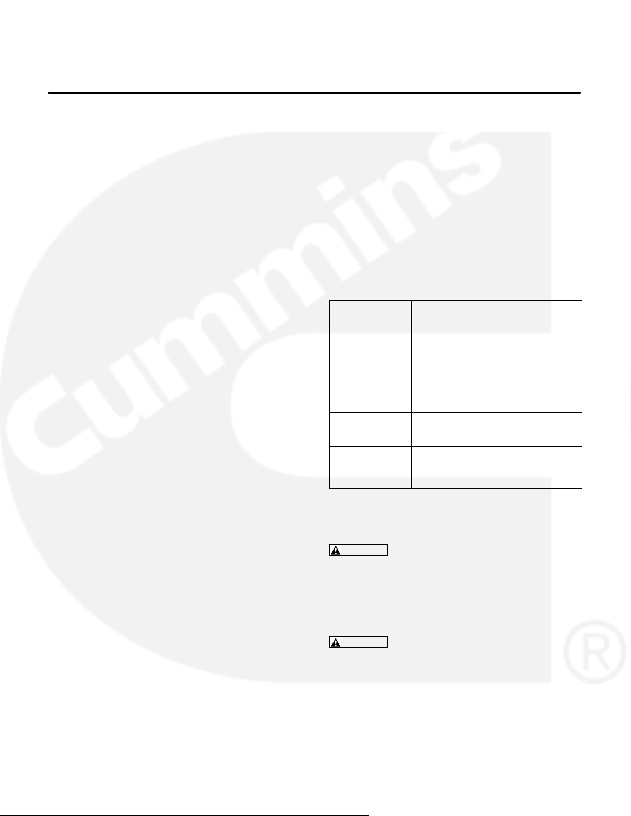
are different in different countries, states and municipalities. Obtain the standards in Table 1 for reference.
Code of Federal
Regulations,
Title 49: Chapter III
and Chapter V
NFPA Nos. 58, 70,
1192
ANSI A119.2
ANSI/RVIA-EGS-1
California Adminis-
trative Code—Title
25, Chapter 3
CAN/CSA-Z240
Recreational Ve-
hicles
Bulletin 946
TABLE 1. REFERENCE CODES AND STANDARDS
CAUTION
Unauthorized modifications or re-
Superintendent of Documents
P. O. Box 371954
Pittsburgh, PA 15250-7954
National Fire Protection Association
470 Atlantic Avenue
Boston, MA 02210
Recreational Vehicle Industry Association
14650 Lee Road
Chantily, VA 22021
State of California Documents Section
P.O. Box 1015
North Highlands, CA 95660
Canadian Standards Association
Housing and Construction Materials Section
178 Rexdale Blvd.
Rexdale, Ontario, Canada M9W 1R3
placement of fuel, exhaust, air intake or speed
control system components that affect engine
emissions are prohibited by law in the State of
California.
ANSI A119.2 / NFPA No. 1192—Recreational
Vehicles
NFPA No. 70, Article 551—Recreational Ve-
hicles and RV Parks
NFPA No. 58—Liquefied Petroleum Gas Code
WARNING
Improper installation can result in
severe personal injury, death and equipment
damage. The installer must be qualified to perform the installation of electrical and mechanical equipment.
5
Page 8
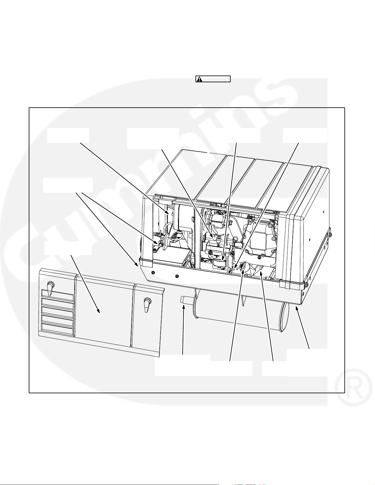
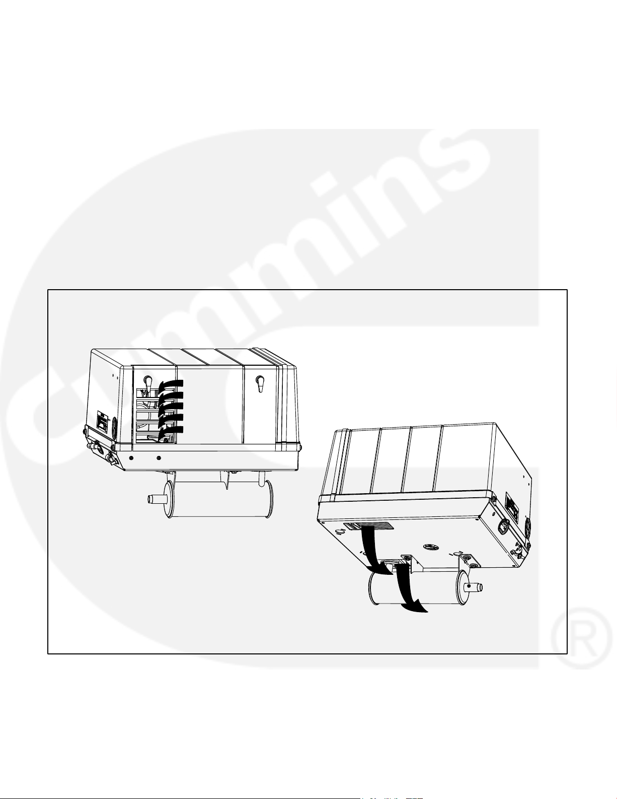
TYPICAL GENSET
Figure 1 illustrates a typical genset. See OUTLINE
DRAWING (Page 27) for installation details: mounting bolt hole locations, connection points (fuel, battery, remote control, AC output and exhaust), sizes
and types of fittings, inlet and outlet air openings,
weight and overall dimensions, etc. See your Onan
dealer for large-scale copies of the drawings and for
full-size floor template 539-4814 for floor opening
cutouts.
CAUTION
Do not tip the genset forward or oil
will spill into the breather. Tip the genset backwards to loosen the shipping skid bolts.
AIR CLEANER
COVER
BATTERY CABLE
CONNECTIONS
MAINTENANCE
ACCESS COVER
ALTITUDE
ADJUST KNOB
(Gasoline Models)
CONTROL
SWITCH
CIRCUIT
BREAKER
MUFFLER
TAILPIECE &
SPARK ARRESTOR
OIL FILL CAP
& DIPSTICK
FIGURE 1. TYPICAL GENSET
6
SPARK
PLUG
OIL DRAIN
THROUGH
BOTTOM OF
BASE
Page 9
Mechanical Installation
CAUTION
side) down while handling the genset. Otherwise, engine oil could drain into and soak the air
filter and cause hard starting and poor operation until the filter is replaced.
The location, mounting and enclosure of a genset
must be such that mounting is secure; engine exhaust, cooling air and fuel vapors are properly
vented and prevented from entering the vehicle;
rain and road debris are prevented from entering the
genset; and ready access is afforded for operating
the genset and performing periodic maintenance.
Avoid tipping the front (service
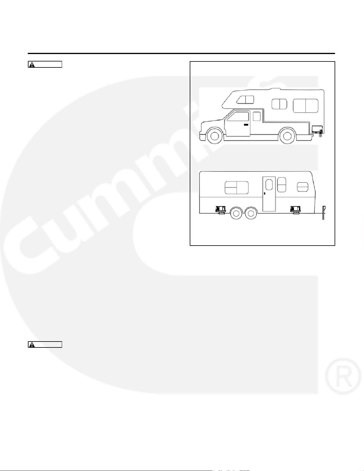
LOCATION
Review Exhaust Connections, Fuel Connections
and Electrical Connections before deciding where
to locate the genset. Figure 2 shows typical genset
locations.
MOUNTING
The genset support structure must be able to resist
the dynamic loads of the genset: cyclical forces of
3 g vertical and 1 g horizontal. A plywood or
particle board floor must be reinforced with steel to
resist the dynamic loads. See Specifications
(Page 23) for the weight of the specific model being
installed.
FIGURE 2. TYPICAL GENSET LOCATIONS
Mounting On Floor: The genset base pan has
four 5/16-18 UNC threaded holes in the bottom for
floor mounting. Use grade 5 screws to mount the
genset. To avoid interference with internal parts, the
screws must not protrude more 1/2 inch (12.7 mm)
from the sheet metal of the base pan.
Mounting Below Floor: Kit 541−0952 is available
from Onan for mounting the genset below the floor.
Carefully follow the instructions in the kit.
WARNING
lead to severe personal injury or death if the
genset falls from the vehicle. Design the structure carefully, follow applicable mounting kit instructions and torque mounting bolts properly.
A weak supporting structure can
7
Page 10

ENCLOSURE
Compartment Dimensions
General
The genset must not share a compartment or ventilation with sources of flammable vapors, such as
batteries and fuel tanks. A genset can ignite flammable vapors.
The genset must be shielded from rain and from debris and water thrown up by the vehicle tires.
Do not duct genset cooling air into the vehicle: the
cooling air may include deadly exhaust gases.
WARNING
DEADLY! — Install a vapor-tight and fire-resistive barrier of approved materials between the
genset and the vehicle interior — Do not duct
genset cooling air into the vehicle for heating.
EXHAUST GAS AND FIRE ARE
Fire and Vapor Barriers
Floor-Mounted Installations: When the genset is
mounted on the floor of the vehicle, construct a vapor-tight, fire-resistive compartment equivalent to
26 gauge galvanized steel to isolate the genset
from the vehicle interior. Seal all openings through
the barrier, such as for bolts and wiring.
Note: If the floor is of wood or other combustible material, it must be lined with 26 gauge galvanized steel
or equivalent material where the distance is less than
3 inch (76 mm) from the muffler, mounting bracket or
tail pipe.
See Specifications (Page 23) and the outline drawing (Page 23) to determine the minimum inside dimensions of a genset compartment. If the compartment has thermal or acoustic insulation, increase
the minimum compartment dimensions by the thicknesses of the insulation. The minimum clearance
required between the genset and the compartment
or its insulation is 1/4 inch (6.4 mm) on the sides
and back, 1/2 inch (12.8 mm) on top and 1-1/4 inch
(31.8 mm) in front. The space on the left side must
be sufficient for making fuel and electrical connections.
Acoustic Insulation
Acoustic and thermal insulation and adhesive
should be Classified as “Self-Extinguishing” for use
at not less than 200
of the compartment with insulation, which absorbs
spilled fuel and oil.
F (90C). Do not line the bottom
Access for Operation and Maintenance
Provide ready access for starting and stopping the
genset and performing all periodic maintenance
procedures.
The compartment floor must not block off the oil
drain plug or air outlets. See your Onan dealer for a
full-size floor cutout template (539-4814).
Below-Floor Installations: When the genset is
mounted below the floor of the vehicle and outside
the interior envelope of the vehicle, install a vaportight, fire-resistive barrier above the genset equivalent to 26 gauge galvanized steel. Seal all openings
through the barrier, such as for bolts and wiring.
Compartment Drain
The floor of the genset compartment must have
holes which allow water and fuel to drain. Refer to
floor template 539-4814 for recommend drain hole
locations.
8
Page 11
VENTILATION
Air for combustion, cooling and ventilation enters
through the column of rectangular openings on the
left front of the genset and exits through the two
openings in the base pan (Figure 3). To prevent
overheating, the installation must minimize the recirculation of warm air back into the genset.
It is recommended that the genset compartment
door have an air opening in line with the genset air
openings and that the opening have a seal around it
that takes up the space between the door and genset, forming an air duct. The opening must have the
equivalent of 40 square inches
(258 cm
“free air” and should be baffled or louvered to keep
out rain. Check with the manufacturer of the louver,
AIR INLETS
2
) or more of
grille or expanded metal to determine how to size
the air opening to obtain the required area on a “free
air” basis.
If the compartment door air inlet is not in line with the
genset air inlets, block any gap between the genset
base pan and the front of the compartment to prevent the hot air discharge below the genset from being recirculated into the air inlets.
The compartment floor must not block off the two
ventilating air outlet openings in the base pan. Also,
the space below the outlets must be unobstructed
and open on at least three sides to let the warm air
disperse. See your Onan dealer for large-scale copies of the drawings and for full-size floor template
539-4814 for floor opening cutouts.
AIR OUTLETS
FIGURE 3. AIR FLOW THROUGH GENSET
9
Page 12

THIS PAGE IS INTENDED TO BE BLANK
10
Page 13

Exhaust Connections
MUFFLER
WARNING
exhaust gases from entering the vehicle — Do
not terminate the exhaust tail pipe underneath
the vehicle or closer than 6 inches (153 mm) to
openings into the vehicle — Route the exhaust
system such that it is protected from damage —
Use approved materials only.
The genset exhaust system must be gas-tight and
prevent entry of exhaust gases into the vehicle.
Figure 4 illustrates installation of the muffler kit
available from Onan. Carefully follow the instructions in the kit. The muffler has a USDA (Forest Service) spark arrestor, meets RVIA EGS-1 requirements for construction and complies with emissions
certification of the genset.
Note: A muffler must have a USDA (Forest Service)
spark arrestor and meet RVIA EGS-1 requirements
for construction (aluminized steel or equivalent and
welded or crimped joints). A genset without a properly installed and maintained spark arresting exhaust
system can cause a brush fire or forest fire and is illegal on federal lands.
EXHAUST GAS IS DEADLY! Keep
FIGURE 4. MUFFLER KIT 541−0916
Liability for damage, injury and warranty expense
due to modification of the exhaust system or to use
of unapproved parts is the responsibility of the person performing the modification or installing the unapproved parts.
CAUTION
placement of fuel, exhaust, air intake or speed
control system components that affect engine
emissions are prohibited by law in the State of
California.
Do not mount the muffler closer than 3 inches
(76 mm) to combustible material (wood, felt, cotton,
organic fibers, etc.) unless it is insulated or shielded.
The temperature rise (above ambient) on adjacent
combustible material must not exceed 117
C).
(65
Unauthorized modifications or re-
F
11
Page 14

TAIL PIPE
1. For the tail pipe, use 18-gauge, 1-1/8 inch I. D.
aluminized steel tubing or material of equivalent heat and corrosion resistance. Do not use
flexible tubing, which is neither gas tight nor durable.
2. Use U-bolt muffler clamps (available from
Onan) for tail pipe connections. Overlapping
pipe should be slotted (Figure 5).
3. Support the tail pipe near its end and at intervals of 3 feet (0.9 m) or less. Use automotivetype tail pipe hangers (available from Onan).
Tail pipe hangers must hang straight down.
Otherwise, the hanger will pull the tail pipe to
side, front or back causing noise and/or damage to the muffler and tail pipe.
4. Do not route the tail pipe near fuel lines and fuel
tanks or closer than 3 inches (76 mm) to combustible material (wood, felt, cotton, organic fibers, etc.) unless it is insulated or shielded. The
temperature rise (above ambient) on adjacent
combustible material must not exceed 117
C).
(65
F
5. To prevent damage to the tail pipe and muffler
while the vehicle is moving, keep it out of the
approach and departure angles and above the
axle clearance line (Figure 6).
3/4 INCH (19 MM) SLOT
(BOTH SIDES)
FIGURE 5. EXHAUST TAIL PIPE CONNECTIONS
DEPARTURE ANGLE AXLE CLEARANCE LINE
FIGURE 6. DEPARTURE ANGLE &
AXLE CLEARANCE LINE
6. Do not terminate the tailpipe underneath the
vehicle. Extend it a minimum of 1 inch (25 mm)
beyond the perimeter of the vehicle (Figure 7).
Support the end of the tail pipe such that it cannot be pushed in and up under the skirt of the
vehicle.
7. Do not terminate the tail pipe such that it is closer than 6 inches (153 mm) to any opening, such
as a door, window, vent or unsealed compartment, into the vehicle interior (Figure 8)
8. Make sure a tail pipe deflector will not cause excessive back pressure (Specifications,
Page 23).
CAUTION
Excessive back pressure may
void emissions certifications and cause engine damage.
12
1 INCH (25 mm)
MINIMUM
LAST TAILPIPE HANGER AS
CLOSE TO END AS PRACTICAL
FIGURE 7. TERMINATING THE TAILPIPE
NO OPENING INTO THE VEHICLE INTERIOR MAY
BE CLOSER THAN 6 INCHES (153 mm) TO THE
END OF THE TAIL PIPE (WITHIN SHADED AREA)
6 in
153 mm
TAILPIPE
FIGURE 8. MINIMUM DISTANCES TO OPENINGS
Page 15

Fuel Connections
See the Operator’s Manual for recommended fuels
and Specifications for fuel consumption rates.
WARNING
Gasoline and LPG are flammable
and explosive and can cause severe personal
injury or death. Do not smoke or allow any
flame, spark, pilot light, arc-producing equipment, switches or other ignition sources around
fuel or fuel components, or in areas sharing ventilation. Keep an ABC fire extinguisher handy.
GASOLINE
Onan recommends a dedicated fuel pickup tube or
a separate fuel tank for the genset. The genset must
never be connected to the fuel supply line of the
vehicle engine—either to a high-pressure system
(pump in tank), which can overpressurize the genset fuel system, or to a vacuum system (pump on
engine), which can cause the genset to starve for
fuel. Some vehicle chassis manufacturers allow
connections to the fuel return line on high pressure
fuel systems. Contact the vehicle chassis manufacturer for approval. Fuel line pressure at the point
where the genset is connected must not exceed
1-1/2 psi under any condition.
WARNING
the genset causing a fire. Genset fuel supply
line pressure must not exceed 1-1/2 psi under
any condition.
SAE J1508 Type D screw & nut hose clamps (Figure 9) are recommended for all fuel hose connections.
For separate fuel pickup tube installations:
1. Contact the vehicle chassis manufacturer regarding installation of the second fuel pickup.
Do not change or remove the fuel fill tube, fill
limiter vent, vapor canister, vapor lines, filler
cap or any other part of the fuel system without
the approval of the vehicle chassis manufacturer. Doing so could affect vehicle engine operation or vehicle emissions regulation compliance.
2. Terminate the genset pickup above the vehicle
pickup to prevent the genset from running the
vehicle out of fuel.
Excessive fuel pressure can flood
BARB
FITTING
HOSE
FUEL
HOSE
FIGURE 9. GASOLINE FUEL CONNECTION
CLAMP
13
Page 16

Note: Federal standards for vehicle fuel tanks may
require the installation of an automatic shutoff valve
at the genset fuel tank pickup to prevent leakage in
the event of a roll-over. Federal standards for vehicle
impact, roll-over and emissions may also apply to a
separate genset fuel tank. Check with the vehicle
chassis manufacture regarding these standards.
For long runs use copper or hot dip coated seamless steel tubing (ASTM A-254) with double-flared
fittings. See Figure 9 for the connection at the genset. Use 1/4 inch I. D. fuel hose (SAE 30-R7 or better) and stainless steel hose clamps.
Run the fuel line at or above the top of the fuel tank to
reduce the risk of siphoning fuel out of the tank if the
line should break. The maximum fuel pump lift is
36 inches (914 mm).
Route gasoline fuel lines away from electrical wiring
and hot engine exhaust components. (Heat can
cause fuel vapor lock.) Fuel lines should be accessible for inspection and replacement, protected from
damage and secured to prevent kinking, contact
with sharp edges and chafing due to vibration.
WARNING
Sparks can ignite gasoline, leading
to severe personal injury or death. Do not run
electrical wiring and fuel lines together. Separate them with conduit or tubing if run through
the same opening. Do not tie them together.
LPG
WARNING
LPG is flammable and explosive
and can cause asphyxiation. NFPA 58, Section
1.6 requires all persons handling LPG to be
trained in proper handling and operating procedures.
Adjust the gas supply pressure (at the gas inlet of
the pressure regulator) to at least 9 inches (229 mm)
Water Column (WC). The pressure must not exceed
13 inches (330 mm) WC.
WARNING
High LPG supply pressure can
cause gas leaks which can lead to fire and severe personal injury or death. LPG supply pressure must be adjusted to Specifications by qualified personnel.
Route LPG fuel lines away from electrical wiring and
hot engine exhaust components. Fuel lines should
be accessible for inspection and replacement, protected from damage and secured to prevent kinking,
contact with sharp edges and chafing due to vibration.
WARNING
Sparks can ignite LPG, leading to
severe personal injury or death. Do not run electrical wiring and fuel lines together. Separate
them with conduit or tubing if run through the
same opening. Do not tie them together.
Route the LPG vent hose (Figure 10) so that it vents
outside the genset compartment.
WARNING
LPG leaks from the vent hose can
lead to explosive accumulations inside the genset compartment. Route the LPG vent hose so
that it vents to the outside.
Follow the Standard for the Storage and Handling of
Liquified Petroleum Gases (NFPA No. 58) when
installing the LPG fuel system. Figure 10 illustrates
a typical LPG fuel system.
For a long fuel line run, use seamless steel tubing
with flared ends. Make flexible hose connections at
the fuel tank and at the genset. Use 3/8-inch I.D. fuel
line for runs up to 3 feet (0.9 m) and 1/2-inch I.D. up
to 15 feet (4.6 m).
14
Page 17

Do not connect the genset fuel supply line to any appliance fuel supply line. The genset can draw fuel
away from other appliances and cause a flame out.
To prevent the possibility of flameout, the fuel supply
system must be designed to deliver sufficient fuel
for normal operation of the genset and other appliances at the expected temperature conditions. It
may be necessary to use a separate fuel tank for the
genset if sufficient fuel cannot be supplied with a
single tank system.
Upon completing the installation, fill the LPG tank
and test every joint and fitting in the LPG supply system using an approved method, such as soap
bubbles.
WARNING
Testing for gas leaks with a flame
can cause a fire or explosion that could lead to
severe personal injury or death. Use approved
methods only.
WARNING
The flameout of an unvented LPG
appliance can lead to explosive accumulations
of gas inside the vehicle and the danger of severe personal injury or death. Do not connect
the genset fuel supply line to any vehicle appliance supply line.
VAPOR SHUTOFF VALVE
FUEL LINE SIZE:
3/8-INCH I.D. UP TO
3 FEET (0.9 m)
1/2-INCH I.D. UP TO
15 FEET (4.6 m)
TWO STAGE REGULATOR
Because variations in fuel, altitude and ambient
temperature affect performance, it might be necessary to make governor and fuel mixture adjustments
once the genset has been installed. See the Service
Manual.
11 INCHES W.C.
OUTLET PRESSURE
DEMAND
REGULATOR
5/8 - 18 45
FLARE FITTING
LPG VENT HOSE
(VENT OUTSIDE
COMPARTMENT)
FUEL SHUTOFF
SOLENOID
FIGURE 10. TYPICAL LPG VAPOR WITHDRAWAL FUEL SYSTEM
15
LPG CARBURETOR
Page 18

THIS PAGE IS INTENDED TO BE BLANK
16
Page 19

Electrical Connections
Do not connect the battery cables to the battery until
Installation Review and Startup (Page 25) has been
completed to prevent accidental starting of the genset during installation.
WARNING
can cause severe personal injury or death. Do
not connect the starting battery until Installation Review and Startup has been completed.
Accidental starting of the genset
GENERATOR CONNECTIONS
The genset is equipped with 104 inch (2.6 m) long
AC power output leads which exit through a 1/2 inch
trade size conduit connector (Figure 11). See Figure
12 for typical connections.
Wiring Methods
Follow the National Electrical Code, especially noting the following:
1. Have a qualified electrician supervise and inspect the installation of all AC wiring.
5. Seal all conduit openings into the vehicle interior to keep out exhaust gas. Apply silicone rubber or an equivalent type of sealant inside and
outside each conduit connector. (Flexible conduit is not vapor-tight and will allow exhaust gas
to enter along the wires if not sealed.)
WARNING
Seal all wiring openings into the vehicle interior to keep out exhaust gas.
6. Bond the genset and all connected AC and DC
equipment and controls to a common grounding point in accordance with applicable codes.
WARNING
fire and electrocution, resulting in severe
personal injury or death. Grounding must
be in accordance with applicable codes.
EXHAUST GAS IS DEADLY!
Faulty grounding can lead to
2. Install vibration-proof switches and controls
that won’t open and close circuits when the vehicle is in motion.
3. Provide ground fault circuit interrupters
(GFCIs)for all convenience power receptacles.
4. Route AC wiring, remote control wiring and fuel
lines separately.
AC OUTPUT
LEADS
FIGURE 11. AC OUTPUT LEADS AND CONDUIT
1/2 INCH CONDUIT
CONNECTOR
17
Page 20

Connecting the Vehicle to Utility Power
When the vehicle has provision for connecting utility
power it must have an approved device to keep the
genset and utility from being interconnected. See
Figure 12 for typical connections.
WARNING
Interconnecting the genset and the
public utility (or any other power source) can
lead to the electrocution of personnel working
on the utility lines, damage to equipment and
fire. An approved switching device must be
used to prevent interconnections.
TO VEHICLE AC
DISTRIBUTION PANEL
GND
L1 N
GNDGND
N
L1L1
120V120V
GENSET
GREEN
WHITE
BLACK
N
TRANSFER SWITCH
FIGURE 12. TYPICAL CONNECTIONS WITH TRANSFER SWITCH AND UTILITY
UTILITY POWER
18
Page 21

REMOTE CONTROL CONNECTIONS
Onan offers three varieties of remote control panel:
Remote start/stop switch with status indicator
light only (Figure 13).
Remote start/stop switch with status indicator
light and hour meter (Figure14).
Remote start/stop switch with status indicator
light and DC voltmeter (Figure15).
The genset has an 8-pin connector for remote control connections (Figure 16). Remote control wiring
harnesses in several lengths are available separately. To make connections to a remote control
panel:
1. Push the remote control wire harness connector through the entrance hole in the side of the
genset housing and snap it together with the
genset connector. If the wiring harness is made
up by others, insulated 18 AWG copper conductors should be used for distances up to 30
feet (9 meters) and heavier gauge conductors
for distances that are greater. Use flexible
sheathing to protect remote control wiring. Figure 17 is a schematic of typical remote control
connections. It identifies the function of each
connector pin number. The remote panel end of
each lead should be marked to identify the connector pin number.
FIGURE 13. REMOTE CONTROL
FIGURE 14. REMOTE CONTROL / HOUR METER
FIGURE 15. REMOTE CONTROL / DC VOLTMETER
2. Route control leads separately from AC power
leads to reduce the possibility of erratic operation due to false induced signals.
3. Seal the opening where the leads enter the vehicle interior with silicone rubber or an equivalent type of sealant to keep out exhaust gas.
WARNING
EXHAUST GAS IS DEADLY!
Seal all wiring openings into the vehicle interior to keep out exhaust gas.
FIGURE 16. REMOTE CONTROL CONNECTOR
19
Page 22

REMOTE CONTROL
PANEL
+
DC
VOLTMETER
OPTIONAL
−
DC VOLTMETER
+
HOUR METER
OPTIONAL
−
HOUR METER
START/STOP SWITCH
+
LED
−
FIGURE 17. SCHEMATIC OF TYPICAL REMOTE CONTROL CONNECTIONS
STATUS
INDICATOR LIGHT
REMOTE RUN
START
GND
STOP
REMOTE CONTROL
CONNECTOR
B
E
F
GH
WIRE END
B
F
C
A
B
WIRE END
(VIEW B−B)
CONNECTOR END
GENSET
CONNECTOR
A
CONNECTOR END
A
D
C
B
A
CONNECTOR END
(VIEW A−A)
WIRE END
E
F
G
H
BATTERY CONNECTIONS
Do not connect the battery cables to the battery until
Installation Review and Startup (Page 25) to prevent accidental starting of the genset during installation.
WARNING
can cause severe personal injury or death. Do
not connect the starting battery until Installation Review and Startup (Page 25).
The genset has a 12 VDC, negative-ground engine
control and cranking system. See Specifications for
the requirements for cranking batteries.
Accidental starting of the genset
Battery Compartment
Batteries must be mounted in a separate compartment from that of the genset and away from sparkproducing equipment. A compartment must have
openings of at least 1.7 square inches (11 square
centimeters) at the top and bottom for ventilation of
battery gasses. It should be mounted such that
spills and leaks will not drip acid on fuel lines, wiring
and other equipment that could be damaged.
WARNING
Arcing can ignite the explosive hydrogen gas given off by the battery, causing severe personal injury. The battery compartment
must be ventilated and must isolate the battery
from spark-producing equipment.
20
Page 23

Battery Cables
Size battery cables according to Table 2. The current path between the genset and the negative (−)
battery terminal must also be able to carry full cranking current without causing excessive voltage drop.
It is highly recommended that a full-length cable be
used to connect the genset to the negative (−) bat-
tery terminal (Figure 18). Note also that codes may
require bonding conductors from the genset and the
battery to the vehicle frame.
If a full-length negative (−) cable is not run from the
battery (Figure 19), all vehicle frame members in
the path of battery cranking currents must have substantial cross sections. The electrical resistance of
riveted or bolted frame joints must also be carefully
considered, especially if the joints will be exposed to
corrosive conditions. A cable must be used to connect the frame to the designated negative (−) terminal on the genset (Figure 19). The cable must be
sized according to Table 2. The genset mounting
bolts are not considered adequate means for
bonding the genset to the vehicle frame, either
for the purpose of carrying cranking currents or
for complying with requirements for genset/
system grounding.
Route battery cables away from fuel lines and hot
engine exhaust components. Battery cables should
be accessible for inspection and replacement, protected from damage and secured to prevent chafing
due to vibration.
TABLE 2. BATTERY CABLE SIZES FOR
TEMPERATURES DOWN TO −20 F (−29C)
TOTAL CABLE LENGTH*
FEET (METERS)
0 to 10 (0 to 3) 2**
11 to 15 (3 to 4.5) 0
16 to 20 (4.5 to 6) 000
* − Add the negative battery cable lengths with the positive
battery cable lengths for the total.
** − A total length of up to 20 feet (6 meters) may be used
in warmer climates or when battery capacity totals at least
1000 CCA (Cold Cranking Amps).
SIZE PER TABLE 2
GENSET
+
−
FIGURE 18. FULL-LENGTH CABLE FROM
BATTERY NEGATIVE (−) TERMINAL
GENSET
+
−
#8 AWG
MINIMUM
VEHICLE FRAME
SIZE PER TABLE 2
CABLE SIZE
AWG
− +
BAT
− +
BAT
WARNING
Routing battery cables with fuel
lines can lead to fire and severe personal injury
or death. Keep battery cables away from fuel
lines.
Terminate the battery cables with appropriately
sized eyelet connectors and connect them to the
genset as shown in Figure 20.
VEHICLE FRAME
FIGURE 19. VEHICLE FRAME AS PATH FROM
BATTERY NEGATIVE (−) TERMINAL
NEG (−) BATTERY
CABLE CONNECTION
& GROUND TERMINAL
POS (+) BATTERY
CABLE CONNECTION
FIGURE 20. BATTERY CABLE CONNECTIONS
21
Page 24

THIS PAGE IS INTENDED TO BE BLANK
22
Page 25

Specifications
GASOLINE MODELS LPG MODELS
4KYD 3.6KYD 3.6KYD 3.3KYD
GENERATOR: 2-Pole Revolving Field, Self-Excited, 1-Phase, Microprocessor Regulated
Power 4000 watts 3600 watts 3600 watts 3300 watts
Frequency 60 Hertz 50 Hertz 60 Hertz 50 Hertz
Voltage 120 volts 230 volts 120 volts 230 volts
Current 33.3 amperes 15.7 amperes 30 amperes 14.3 amperes
Speed 3600 rpm 3000 rpm 3600 rpm 3000 rpm
FUEL CONSUMPTION:
No load
Half load
Full load
ENGINE: 1-Cylinder, 4-Stroke Cycle, Spark-Ignited, OHV, Air Cooled, Mechanically Governed
Bore 3.11 inch (79 mm) 3.11 inch (79 mm)
Stroke 2.44 inch (62 mm) 2.44 inch (62 mm)
Displacement 18.5 inch3 (304 cc) 18.5 inch3 (304 cc)
Compression Ratio 8.5 : 1 8.5 : 1
Oil Capacity 1.6 quart (1.5 l) 1.6 quart (1.5 l)
Intake Valve Lash (Cold) 0.002 inch (0.05 mm) 0.002 inch (0.05 mm)
Exhaust Valve Lash (Cold) 0.002 inch (0.05 mm) 0.002 inch (0.05 mm)
Spark Plug Tightening Torque 13 lbs-ft (17 N-m) 13 lbs-ft (17 N-m)
Ignition Timing (magneto) 25 BTDC, non-adjustable 25 BTDC, non-adjustable
Magneto Air Gap 0.009-0.015 inch (0.23-0.38 mm) 0.009-0.015 inch (0.23-0.38 mm)
Spark Plug Gap 0.025 inch (0.64 mm) 0.020 inch (0.51 mm)
DC SYSTEM:
Nominal Battery Voltage 12 volts 12 volts
Min. Battery Rating: Cold
Cranking Amps (CCA)
@ 0 F (−18 C)
Battery Charging Current − 10 amp (regulated) − 10 amp (regulated)
INSTALLATION:
Weight with Muffler 172.6 lb (78.3 Kg) 172.6 lb (78.3 Kg)
Minimum Compartment Size
(H x D x W)
Minimum Free Air Inlet Area 40 inch2 (258 cm2) 40 inch2 (258 cm2)
Muffler Outlet Collar O. D. 1.13 inch 1.13 inch
Max. Exhaust Back Pressure 32 inch WC 32 inch WC
Fuel Connection 1/4 inch barb fitting for gasoline hose 5/8-18UNC, SAE 45 Flare Fitting
LPG Vapor Supply Pressure −
1. See the Installation Manual for additional considerations when sizing the genset compartment.
1
0.29 gph (1.1 l/h)
0.48 gph (1.8 l/h)
0.71 gph (2.7 l/h)
14.55 inch x 20.13 inch x 26.31 inch
(369.25 mm x 511.3 mm x 668.3 mm)
0.21 gph (0.79l/h)
0.37 gph (1.4 l/h)
0.58 gph (2.2 l/h)
450 450
1.5 lbs/h (0.7 kg/h)
2.2 lbs/h (1.0 kg/h)
3.3 lbs/h (1.5 kg/h)
14.55 inch x 20.13 inch x 26.31 inch
(369.25 mm x 511.3 mm x 668.3 mm)
9-13 inch (228-330 mm)
Water Column (WC)
1.1 lbs/h (0.5 kg/h)
2.0 lbs/h (0.9 kg/h)
2.9 lbs/h (1.3 kg/h)
23
Page 26

THIS PAGE IS INTENDED TO BE BLANK
24
Page 27

Installation Review and Startup
INSTALLATION REVIEW
Before starting the genset inspect the installation
and check (
be answered “YES”. If an item cannot be checked,
provision must be made to satisfy the requirement.
[ ] Is the control panel on the genset easily acces-
sible for starting and stopping the genset and
resetting the circuit breaker?
[ ] Is there easy access for checking and adding
engine oil, replacing the spark plug and changing the air filter?
[ ] Is the genset securely bolted in place?
[ ] Are all specified clearances provided?
[ ] Are the air inlet and outlet openings free of ob-
structions?
[ ] Is there access for draining engine oil?
[ ] Are all tailpipe connections tight and all hang-
ers and support straps secure?
[ ] Does the tailpipe terminate at least 1 inch
(25 mm) beyond the perimeter of the vehicle
and at least 6 inches (153 mm) away from any
opening into the vehicle?
) each of the following questions if it can
[ ] Has the fuel line been secured at sufficient in-
tervals to prevent chaffing and contact with
sharp edges, electrical wiring and hot exhaust
parts?
STARTUP
When all the items on the Installation Review check
list have been checked, connect the battery cables
to the battery, positive (+) cable first.
WARNING
that can cause severe personal injury. Do not
smoke near batteries. Keep flames, sparks, pilot
lights, electrical arcs and arc-producing equipment and all other ignition sources well away.
Read the Operator’s Manual and perform the maintenance and pre-start checks instructed. The genset is shipped from the factory with the proper level
of engine oil, which should nevertheless be checked
before the genset is started. Start and operate the
genset, following all the instructions and safety precautions in the Operator’s Manual.
WARNING
operate the genset when the vehicle is indoors
or where exhaust can accumulate.
Batteries give off explosive gases
EXHAUST GAS IS DEADLY! Do not
[ ] Is the genset located outside the vehicle interior
or separated by approved vapor-tight and fireresistive materials?
[ ] Are all openings into the vehicle, such as for AC
wiring, sealed to keep out engine exhaust? Are
AC conduit connectors sealed inside and outside?
[ ] Have all AC connections been inspected and
approved?
[ ] Has a properly sized battery for genset starting
and control been installed in a ventilated
compartment isolated from the genset?
[ ] Have properly sized battery cables been
installed and secured at sufficient intervals to
prevent chaffing and contact with sharp edges,
fuel lines and hot exhaust parts?
[ ] Are all fuel connections tight?
Check for fuel and exhaust leaks and unusual
noises while the genset is running under full and intermediate loads. Do not place the genset in service
until all fuel and exhaust leaks have been fixed and
operation is satisfactory.
HOT AIR RECIRCULATION TEST
A representative installation of the genset must be
tested to determine that the genset will not overheat
due to recirculation of hot air back into the genset.
Test Method
1. Complete a representative installation.
2. Set up a load bank to run the genset at rated
full-load.
3. Conduct the test at a location where the ambient air temperature will remain between 60F
and 100F (16C and 38C).
25
Page 28

WARNING
LOCATION
EXHAUST GAS IS DEADLY! Do
not operate the genset when the vehicle is
parked indoors or where exhaust can accumulate.
4. Measure temperatures with thermocouples not
heavier than No. 24 AWG (0.21 mm
2
).
ings. Table 2 illustrates how the data can be arranged for recording and analysis.
TABLE 2. TEMPERATURE DATA
TEMPERATURE C (F)
THERMOCOUPLE
Time Of Reading
A. Measure genset inlet air temperature with
one thermocouple tied in the middle of the
inlet air grille (Figure 18).
B. Measure ambient air temperature with a
shielded thermocouple within 4 feet
(1.2 meters) of the genset and at approximately the same height. Make sure the
thermocouple will not be affected by warm
air discharged from the genset or by sunlight. Use 2 inch diameter white PVC piping at least 6 inches long as a thermocouple shield.
5. Close all compartment doors and run the genset at full-load for at least an hour. Record temperatures at 15 minute intervals until they stabilize. Temperature is considered stable when
there is no change in three consecutive read-
AMBIENT AIR
AMBIENT AIR
INLET AIR
Test Requirement
The rise in inlet air temperature over ambient air
temperature must not exceed 15F (8C). A rise in
inlet air temperature indicates hot air recirculation. If
the rise exceeds the requirement, steps must be
taken to reduce recirculation to an acceptable level.
Review VENTILATION (Page 8).
CAUTION
tures could reduce maximum genset power output if the air temperature rise measured in this
test is on the high end of the acceptable range.
This guide is for air flow testing only and does
not completely verifiy Cooling for generators
that use both air and liquid cooling systems.
High ambient operating tempera-
INLET AIR
FIGURE 21. THERMOCOUPLE LOCATIONS FOR HOT AIR RECIRCULATION TEST
26
Page 29

500-3717
OUTLINE DRAWING
27
Page 30

0611-1267
WIRING DIAGRAM—60 HZ
28
Page 31

0611-1268-1
WIRING DIAGRAM—50 HZ
29
Page 32

KYD
0611-1268-2
30
OUTPUT CONNECTIONS—50 HZ
Page 33

Page 34

Cummins Power Generation
1400 73rd Ave. NE
Minneapolis, MN 55432 USA
Phone 1 763 574 5000
Toll-free 1 800 888 6626
Fax 1 763 574 5298
Email www.cumminsonan.com/contact
www.cumminsonan.com
CumminsR, OnanR, the “C” logo, and “Performance you rely on.”
are trademarks of Cummins Inc.
E2012 Cummins Power Generation, Inc. All rights reserved.
 Loading...