

Page 1

Installation Manual
RV Generator Set
HGJAA (Spec A-E)
English
Original Instructions
HGJAB (Spec A-E)
HGJAC (Spec A-D)
7-2011 983-0600 (Issue 10)
Page 2

Page 3

Table of Contents
1. SAFETY PRECAUTIONS .............................................................................................................. 1
1.1 Gasoline and Propane Are Flammable and Explosive ........................................................... 1
1.2 Engine Exhaust is Deadly....................................................................................................... 1
1.3 Generator Voltage is Deadly................................................................................................... 2
1.4 Moving Parts Can Cause Severe Personal Injury or Death ................................................... 2
1.5 Battery Gas is Explosive......................................................................................................... 2
1.6 General Precautions ............................................................................................................... 2
2. INTRODUCTION............................................................................................................................ 5
2.1 About this Manual................................................................................................................... 5
2.2 Installation Codes and Standards for Safety .......................................................................... 5
2.3 Outline Drawings..................................................................................................................... 6
2.4 Lifting and Handling Genset ................................................................................................... 6
3. LOCATION, MOUNTING AND VENTILATION .............................................................................. 9
3.1 Location .................................................................................................................................. 9
3.2 Heat, Fire and Exhaust Barriers ........................................................................................... 10
3.2.1 Insulating Materials ...................................................................................................... 10
3.2.2 Fire and Exhaust Barriers ............................................................................................ 10
3.2.3 Thermal Insulation for Model HGJAC—Below-Floor Mounted .................................... 10
3.2.4 Thermal Insulation for Model HGJAC—Above-Floor Mounted .................................... 10
3.3 Mounting ............................................................................................................................... 10
3.3.1 Mounting Structure and Hardware ............................................................................... 10
3.3.2 Below-Floor Mounting .................................................................................................. 11
3.4 Ventilation ............................................................................................................................. 11
4. EXHAUST CONNECTIONS......................................................................................................... 13
4.1 Muffler—Models HGJAA / HGJAB........................................................................................ 13
4.2 Muffler—Model HGJAC ........................................................................................................ 14
4.3 Tail Pipe ................................................................................................................................ 15
5. FUEL CONNECTIONS................................................................................................................. 19
5.1 Gasoline—Model HGJAA (EFI) ............................................................................................ 19
5.1.1 Remote Fuel Pump Kit................................................................................................. 19
5.1.2 Fuel Tank ..................................................................................................................... 20
5.1.3 Fuel Supply Line Pump to Genset ............................................................................... 20
983-0600 (Issue 10) i
Page 4

Table of Contents 7-2011
5.1.4 Vapor and Fuel Return Line Requirements ................................................................. 21
5.1.5 Routing Fuel Lines....................................................................................................... 22
5.2 Gasoline—Models HGJAB/HGJAC ...................................................................................... 22
5.2.1 Fuel Tank ..................................................................................................................... 22
5.2.2 Fuel Lines .................................................................................................................... 23
5.2.3 Routing Fuel Lines....................................................................................................... 24
5.3 Evaporative system installation ............................................................................................ 24
5.3.1 System Components.................................................................................................... 25
5.3.2 Fuel Tank ..................................................................................................................... 25
5.3.3 Carbon Canister........................................................................................................... 26
5.3.4 Carburetor Fuel System Generator Sets ..................................................................... 29
5.3.5 Fuel Injection (EFI) System Generator Sets ................................................................ 29
5.3.6 Fuel Hoses................................................................................................................... 31
5.4 Low Pressure Propane Supply (Vapor Withdrawal) ............................................................. 31
5.5 High Pressure Propane Supply (Liquid Withdrawal) ............................................................ 33
6. ELECTRICAL CONNECTIONS.................................................................................................... 35
6.1 AC Power Output Connections............................................................................................. 35
6.1.1 Wiring Methods ............................................................................................................ 35
6.1.2 Connecting Shore Power............................................................................................. 36
6.2 Remote Control Connections................................................................................................ 37
6.3 Battery Connections.............................................................................................................. 40
6.3.1 Battery Compartment................................................................................................... 40
6.3.2 Battery Cables ............................................................................................................. 41
6.3.3 Battery Cable Connections at Genset ......................................................................... 42
6.3.4 Genset (Equipment) Grounding Screw ........................................................................ 42
7. INSTALLATION REVIEW AND STARTUP .................................................................................. 45
7.1 Hot Air Recirculation Test ..................................................................................................... 45
7.1.1 Test Method ................................................................................................................. 45
7.1.2 Test Requirement ........................................................................................................ 46
7.2 Installation Review ................................................................................................................ 46
7.3 Startup .................................................................................................................................. 47
8. SPECIFICATIONS ....................................................................................................................... 49
APPENDIX A. WIRING DIAGRAMS................................................................................................. 53
Wiring Diagrams.......................................................................................................................... 55
APPENDIX B. OUTLINE DRAWINGS .............................................................................................. 57
ii 983-0600 (Issue 10)
Page 5

7-2011 Table of Contents
Outline Drawings ......................................................................................................................... 59
983-0600 (Issue 10) iii
Page 6

Table of Contents 7-2011
This page is intentionally blank.
iv 983-0600 (Issue 10)
Page 7

1 Safety Precautions
Thoroughly read the OPERATOR'S MANUAL before operating the genset. Safe operation
and top performance can only be obtained when equipment is properly operated and
maintained.
The following symbols in this manual alert you to potential hazards to the operator, service
person and equipment.
DANGER: alerts you to an immediate hazard that will result in severe personal
injury or death.
WARNING: alerts you to a hazard or unsafe practice that can result in severe personal
injury or death.
CAUTION: alerts you to a hazard or unsafe practice that can result in personal injury or
equipment damage.
Electricity, fuel, exhaust, moving parts and batteries present hazards which can result in severe
personal injury or death.
1.1 Gasoline and Propane Are Flammable and Explosive
· Do not smoke or turn electrical switches ON or OFF where fuel fumes are present or in
areas sharing ventilation with fuel tanks or equipment. Keep flames, sparks, pilot lights,
arc-producing equipment and all other sources of ignition well away.
· Fuel lines must be secured, free of leaks and separated or shielded from electrical wiring.
· Leaks can lead to explosive accumulations of gas. LPG sinks when released and can
accumulate inside housings and basements and other below-grade spaces. Prevent leaks
and the accumulation of gas.
1.2 Engine Exhaust is Deadly
· Inspect for exhaust leaks at every startup and after every eight hours of running.
· Prior to every startup and after every eight hours of running, all carbon monoxide detectors
must be tested and confirmed to be working in accordance with the manufacture's
instructions or owners manual.
· Learn the symptoms of carbon monoxide poisoning in the genset Operator's Manual.
· Never occupy the vehicle while the genset is running unless the vehicle is equipped with a
working carbon monoxide detector.
· Do not operate the genset when the vehicle is parked in a confined space, such as a
garage.
· Disable the automatic genset starting feature (AGS) of an inverter-charger or other
automatic starting device before storing the vehicle or parking it in a garage or other
confined space.
· The exhaust system must be installed in accordance with the genset Installation Manual.
983-0600 (Issue 10) 1
Page 8

1. Safety Precautions 7-2011
· Engine cooling air must not be used for heating the vehicle.
1.3 Generator Voltage is Deadly
· Disable the automatic genset starting feature (AGS) of an inverter-charger or other
automatic starting device before servicing the genset.
· Generator electrical output connections must be made by a trained and experienced
electrician in accordance with applicable codes.
· The genset must not be connected to shore power (utility). Back-feed to shore power can
cause electrocution and damage to equipment. An approved switching device must be
used to prevent interconnections.
· Use caution when working on live electrical equipment. Remove jewelry, make sure
clothing and shoes are dry, stand on a dry wooden platform or rubber insulating mat and
use tools with insulated handles.
1.4 Moving Parts Can Cause Severe Personal Injury or Death
· Disable the automatic genset starting feature (AGS) of an inverter-charger or other
automatic starting device before servicing the genset.
· Do not wear loose clothing or jewelry near moving parts such as PTO shafts, fans, belts
and pulleys.
· Keep hands away from moving parts.
· Keep guards in place over fans, belts, pulleys, and other moving parts.
1.5 Battery Gas is Explosive
· Wear safety glasses.
· Do not smoke.
· To reduce arcing when disconnecting or reconnecting battery cables, always disconnect
the negative (-) battery cable first and reconnect it last.
1.6 General Precautions
· Keep children away from the genset.
· To prevent accidental or remote starting while working on the genset, disconnect the
negative (-) battery cable at the battery.
· Keep the genset and its compartment clean. Excess oil and oily rags can catch fire. Do not
store gear in the compartment it can restrict cooling air.
· Make sure all fasteners are secure and torqued properly.
· Do not work on the genset when mentally or physically fatigued or after consuming alcohol
or drugs.
2 983-0600 (Issue 10)
Page 9

7-2011 1. Safety Precautions
· You must be trained and experienced to make adjustments while the genset is
running—hot, moving or electrically live parts can cause severe personal injury or death.
· Used engine oil has been identified by some U. S. state and federal agencies as causing
cancer or reproductive toxicity. Do not ingest, inhale, or contact used oil or its vapors.
· Benzene and lead in some gasoline have been identified by some state and federal
agencies as causing cancer or reproductive toxicity. Do not ingest, inhale or contact
gasoline or its vapors.
· Keep multi-class ABC fire extinguishers readily at hand. Class A fires involve ordinary
combustible materials such as wood and cloth. Class B fires involve combustible and
flammable liquids and gaseous fuels. Class C fires involve live electrical equipment. (ref.
NFPA No. 10)
· Genset installation and operation must comply with all applicable local, state and federal
codes and regulations.
983-0600 (Issue 10) 3
Page 10

1. Safety Precautions 7-2011
This page is intentionally blank.
4 983-0600 (Issue 10)
Page 11
2 Introduction
2.1 About this Manual
WARNING: Improper installation can result in severe personal injury, death and
equipment damage. The installer must be trained and experienced in the
installation of electrical, mechanical, fuel and exhaust equipment.
WARNING: This genset is not a life support system. It can stop without warning.
Children, persons with physical or mental limitations, and pets could suffer
personal injury or death. A personal attendant, redundant power or an alarm
system must be used if genset operation is critical.
CAUTION: Unauthorized modifications or replacement of fuel, exhaust, air intake or speed
control system components that affect engine emissions are prohibited by law in
the State of California.
This manual is a guide for the installation of the HGJAA and HGJAB Series of generator sets
(gensets). Proper installation is essential for top performance. Read through this manual before
starting the installation. Leave this manual with the vehicle.
This manual addresses the following aspects of the installation:
· Location, Mounting and Ventilation
· Exhaust Connections
· Fuel Connections
· Electrical Connections
· Startup
See the Operator's Manual for operation and maintenance instructions.
NOTE: Manuals are updated from time to time to reflect changes in the equipment
and its specifications. For this reason, only the copy of the installation
manual supplied with the genset should be used as a guide for the
installation.
2.2 Installation Codes and Standards for Safety
CAUTION: The Warranty applies only when this genset is installed in a Recreational Vehicle.
The installer bears sole responsibility for the selection of the appropriate genset, for its proper
installation and for obtaining approvals from the authorities (if any) having jurisdiction over the
installation. These sets meet the basic requirements of the Standard for Safety for Engine
Generator Sets for Recreational Vehicles, ANSI/RVIA EGS-1. They are suitable for installation
in accordance with:
· NFPA No. 1192—Recreational Vehicles
· NFPA No. 70, Article 551—Recreational Vehicles and RV Parks
· NFPA No. 58—Liquefied Petroleum Gas Code
983-0600 (Issue 10) 5
Page 12
2. Introduction 7-2011
· CSA Electrical Bulletin 946—Requirements for Internal Combustion Engine-Driven Electric
Generators for Use in Recreational Vehicles
Federal, State and local codes, such as the California Administrative Code—Title 25 (RV
installation), might also be applicable. Installation codes and recommendations can change from
time-to-time and are different in different countries, states and municipalities. It is recommended
that the standards in Table 1 be obtained for reference.
TABLE 1. REFERENCE CODES AND STANDARDS
Code of Federal
Regulations, Title
49: Chapter III
and Chapter V
NFPA No 58, 70,
1192
ANSI/RVIA-EGS-
1
California
Administrative
Code—Title 25,
Chapter 3
CAN/CSA-Z240
Recreational Canadian Standards Association Housing and Construction Materials Section 178 Rexdale Blvd.
Vehicles Bulletin Rexdale, Ontario, Canada M9W 1R3
946
Superintendent of Documents P. O. Box 371954 Pittsburgh, PA 15250-7954
National Fire Protection Association 470 Atlantic Avenue Boston, MA 02210
Recreational Vehicle Industry Association 14650 Lee Road Chantily, VA 22021
State of California Documents Section P.O. Box 1015 North Highlands, CA 95660
2.3 Outline Drawings
See the Appendix B on page 57 at the end of the manual for installation details: mounting bolt
hole locations, connection points (fuel, battery, exhaust, remote control, AC output), sizes and
types of fittings, cooling air openings, weight, and overall dimensions. See your Onan dealer for
a large-scale Outline Drawing and full-size floor cutout template.
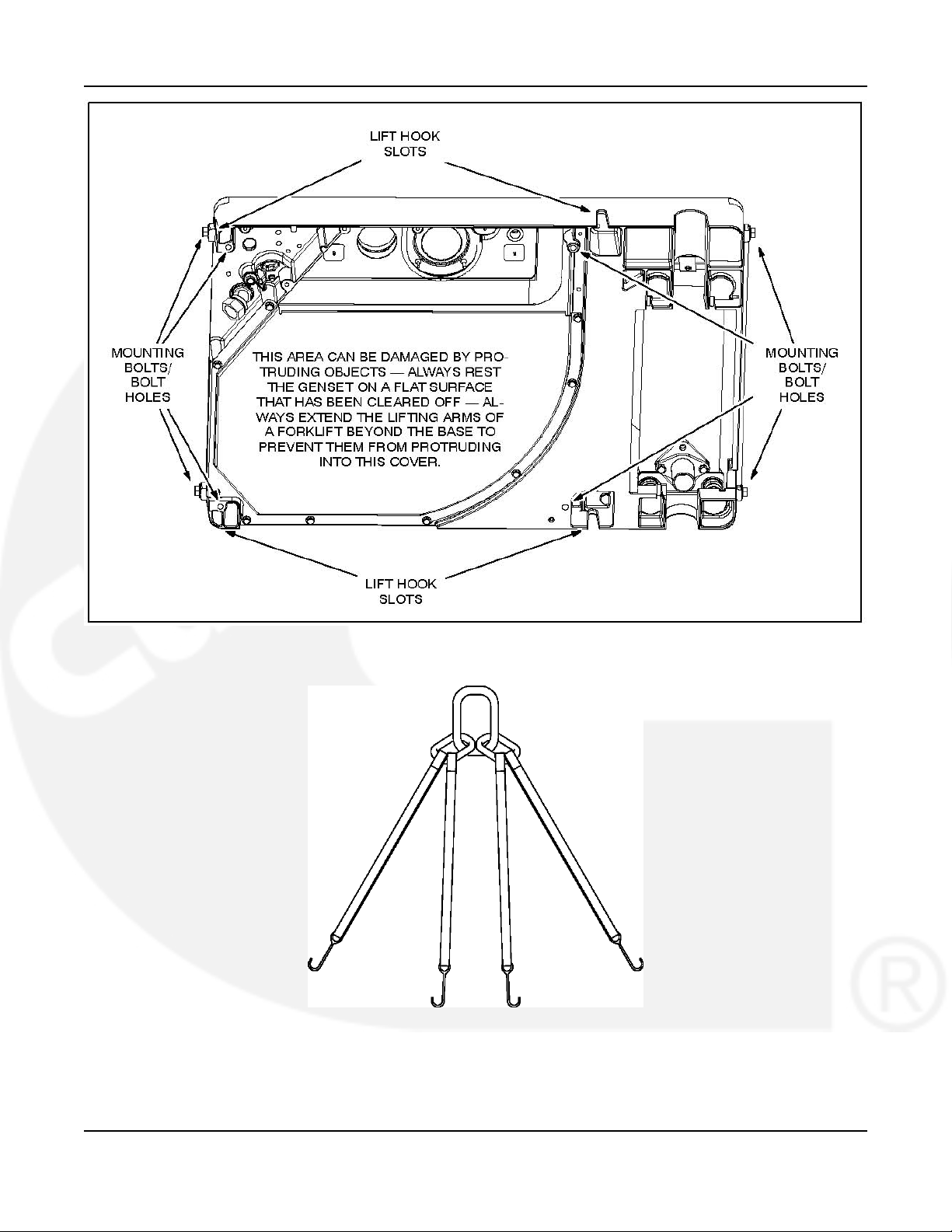
2.4 Lifting and Handling Genset
Figure 1 illustrates the four lift hook slots for genset lifting. A lifting rig must spread the hook
straps such that they do not crush or bend parts such as the control box, air filter and fuel lines
while lifting. See Specifications (Chapter 8) for the weight of the genset and make provisions
accordingly for safe handling.
CAUTION: Avoid tipping the front (service side) down while handling the genset. Engine oil
could drain into and soak the air filter to cause hard starting and poor operation.
The underside of the genset can be damaged by protruding objects — Always rest
the genset on a flat surface that has been cleared off — Always extend the lifting
arms of a forklift beyond the base of the genset to prevent them from protruding
into the underside cover.
6 983-0600 (Issue 10)
Page 13
7-2011 2. Introduction
FIGURE 1. GENSET LIFT-HOOK SLOTS—MOUNTING BOLT HOLES—AREA THAT CAN BE
DAMAGED
FIGURE 2. LIFTING HOOK SLING - EXAMPLE ONLY
Contact local sling or rigging supplier for specifications
983-0600 (Issue 10) 7
Page 14

2. Introduction 7-2011
This page is intentionally blank.
8 983-0600 (Issue 10)
Page 15
3 Location, Mounting and Ventilation
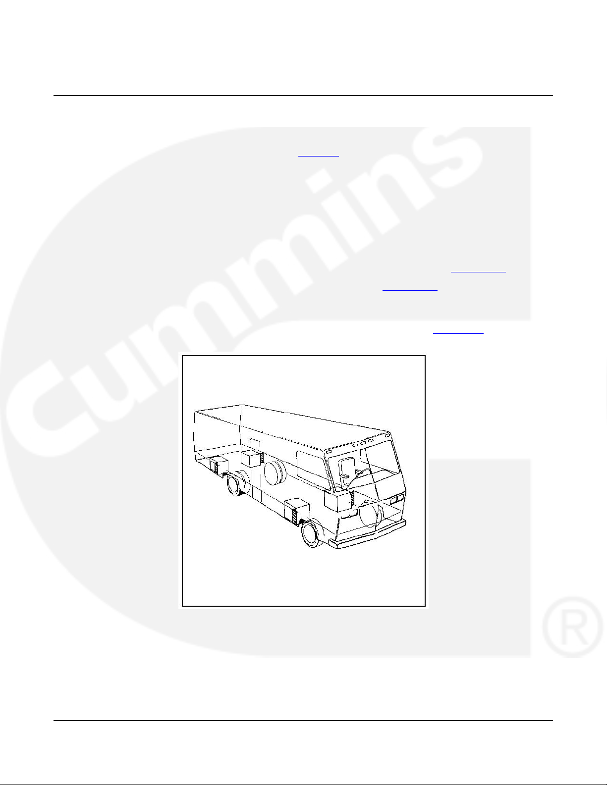
3.1 Location
Typical genset locations are illustrated in Figure 3. The location must provide:
1. Ready access for starting and stopping the genset and performing all periodic maintenance
2. Separation from sources of flammable vapors, such as batteries and fuel tanks, which the
genset can ignite
3. Access for connecting and disconnecting fuel lines, battery cables, remote control wiring
and AC wiring
4. Access from below for draining engine oil and changing the oil filter
5. Unobstructed space below the genset for proper cooling air flow (see Section 3.4 ).
6. Ground clearance of at least 12 inches (305 mm) (see Section 3.4 ).
7. Space to mount the genset with at least 1/2 inch (12.7 mm) clearance at the top and any
side of the genset. These minimum clearances apply to any thermal or acoustic insulation
with which a compartment may be lined. See Specifications (Chapter 8) for minimum
compartment dimensions.
FIGURE 3. TYPICAL GENSET LOCATIONS
983-0600 (Issue 10) 9
Page 16

3. Location, Mounting and Ventilation 7-2011
3.2 Heat, Fire and Exhaust Barriers
3.2.1 Insulating Materials
Acoustic/thermal insulation and adhesive must be Classified as “Self-Extinguishing" at not less
than 200°F (90°C). Do not line the bottom of a compartment with insulation, which absorbs fuel
and oil.
3.2.2 Fire and Exhaust Barriers
Barriers to provide vapor and fire resistance must be installed between the genset and the
interior of the vehicle if the genset is mounted below the floor. If the genset is mounted in a
compartment on the floor of the vehicle, the entire compartment (except the floor) must be lined
with vapor and fire resistive materials. All seams and openings in the barriers for wiring,
mounting screws and so forth must be sealed. Use approved materials (26 gauge galvanized
steel or equivalent). See NFPA 1192 for details.
WARNING: EXHAUST GAS AND FIRE ARE DEADLY! Construct a suitable vapor and fire
barrier of approved materials between the genset and vehicle interior.
3.2.3 Thermal Insulation for Model HGJAC—Below-Floor
Mounted
If the floor is of combustible material, such as plywood, cover the floor above the genset and
any side wall around the genset with 1/4 to 1/2 inch (6.4 to 12.7 mm) thick, 4 lb/ft3(0.0167
kg/m3) density fiberglass thermal insulation with aluminum foil facing at least 0.001 inch (0.025
mm) thick. Secure the insulation every 12 inches (304 mm) to the surfaces being protected by
means of mechanical fasteners and washers as least 1 inch (25 mm) in diameter.
3.2.4 Thermal Insulation for Model HGJAC—Above-Floor
Mounted
If of combustible material, such as plywood, line the compartment and door, but not the floor,
with 1/4 to 1/2 inch (6.4 to 12.7 mm) thick, 4 lb/ft3(0.0167 kg/m3) density fiberglass thermal
insulation with aluminum foil facing at least 0.001 inch (0.025 mm) thick. Secure the insulation
every 12 inches (304 mm) to the surfaces being protected by means of mechanical fasteners
and washers as least 1 inch (25 mm) in diameter. See Specifications (Page Chapter 8)
regarding minimum compartment dimensions.
3.3 Mounting
3.3.1 Mounting Structure and Hardware
Support the genset on a structure able to resist the dynamic weight of the genset: ±3 g-force
vertical and ±1 g-force horizontal. See Specifications (Chapter 8) for the weight of the specific
model being installed. Secure the genset with four 3/8 inch thread-forming bolts in the ends or
bottom of the base (Figure 1). Torque the bolts to 31 lb-ft (42 N-m).
WARNING: The genset support structure must be designed and installed to support and
restrain the dynamic weight of the genset. Failure to do so can result in the
genset dropping onto the roadway causing property damage, severe
personal injury and death.
10 983-0600 (Issue 10)
Page 17
7-2011 3. Location, Mounting and Ventilation
3.3.2 Below-Floor Mounting
Below-floor mounting kits are available from Onan. Carefully follow the instructions in the kit.
Reinforce generator set with steel to resist the dynamic weight. Do not mount the genset within
the approach or departure angles of the vehicle or below the axle line (Figure 10).
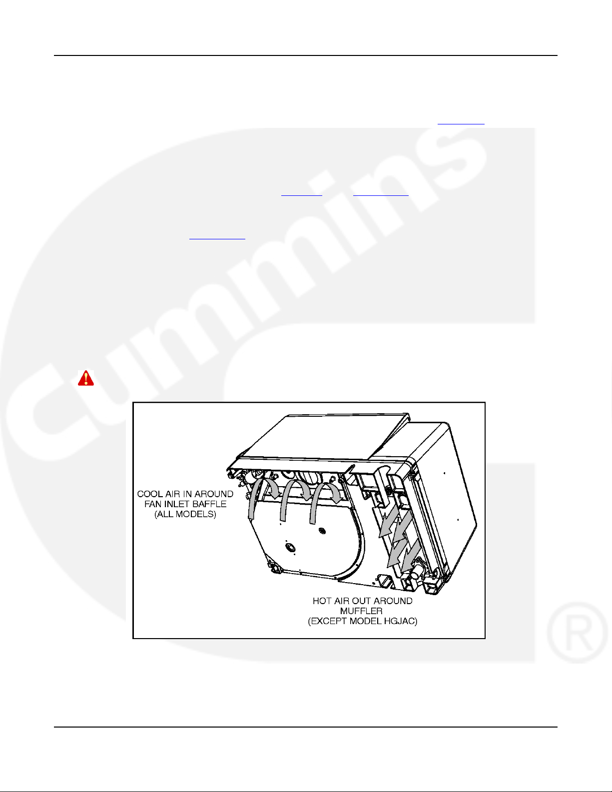
3.4 Ventilation
Unrestricted air flow into and out of the genset for cooling and ventilation is essential for proper
genset performance and service life (Figure 4). See Section 7.1 .
1. See your Onan dealer for a full-size floor template to accurately locate the air inlet and
outlet openings when installing the genset on the floor of the vehicle. The template is
illustrated in Section 2.3.
2. At least 6 inches (152 mm) of unobstructed space below the genset that is open on at least
three sides is required for proper cooling air flow.
3. A ground clearance of at least 12 inches (305 mm) is recommended to reduce the amount
of dust pulled in by the cooling fan and the likelihood of blocking air flow by parking curbs
or logs.
4. Shield the air inlet in the bottom of the genset from direct road splash when the genset is
located in line with the road wheels.
5. Do not duct genset cooling air into the vehicle for heating.
WARNING: EXHAUST GAS IS DEADLY! Do not duct genset cooling air into the vehicle
for heating.
FIGURE 4. COOLING AIR FLOW INTO AND OUT OF GENSET
983-0600 (Issue 10) 11
Page 18

3. Location, Mounting and Ventilation 7-2011
This page is intentionally blank.
12 983-0600 (Issue 10)
Page 19
4 Exhaust Connections
The exhaust system must be gas-tight and designed to limit entry of exhaust gases into the
vehicle.
WARNING: EXHAUST GAS IS DEADLY! To keep exhaust gases from entering the vehicle
do not terminate the exhaust tailpipe underneath the vehicle or closer than
specified to openings into the vehicle (Figure 9) or route it such that it is
likely to be damaged (Figure 10). Use approved materials and parts only.
CAUTION: Unauthorized modifications or replacement of fuel, exhaust, air intake or speed
control system components that affect engine emissions are prohibited by law in
the State of California.
4.1 Muffler—Models HGJAA / HGJAB
The muffler is mounted inside the genset enclosure. It has a USDA (Forest Service) spark
arrestor and meets RVIA EGS-1 construction requirements.
A genset without a properly installed and maintained spark arresting exhaust system can cause
a forest fire. It is illegal on federal lands. Liability for damage, injury and warranty expense due
to the modification of the exhaust system or to the use of unapproved parts is the responsibility
of the person performing the modification or installing the unapproved parts.
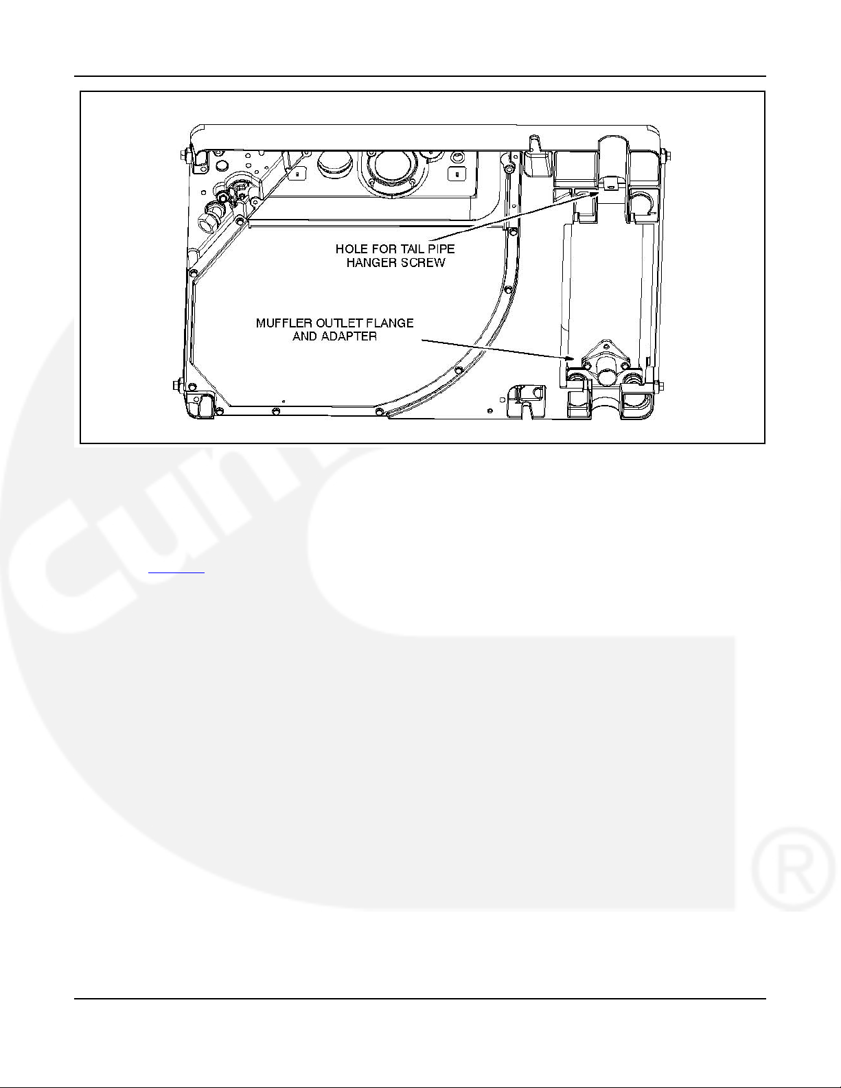
The muffler has a short adapter bolted to its outlet flange (Figure 5). Clamp the tail pipe to the
adapter. See Section 4.3 regarding materials, clamps, support, routing and termination.
Alternatively, a tail pipe with elbow and flange can be bolted to the muffler flange to run straight
out the tunnel in the front or the tunnel in the back of the genset base. See ( Section 2.3 ) for
muffler flange dimensions. Make sure to use a suitable flange gasket. Use the hole shown on
the drawing for the tail pipe hanger if the tail pipe runs out the front. See Section 4.3 regarding
materials, clamps, support, routing and termination. Do not route the tail pipe this way when the
genset is mounted on a combustible floor.
983-0600 (Issue 10) 13
Page 20
4. Exhaust Connections 7-2011
FIGURE 5. OUTLET FLANGE AND ADAPTER ON MODELS WITH INTERNALLY MOUNTED
MUFFLERS
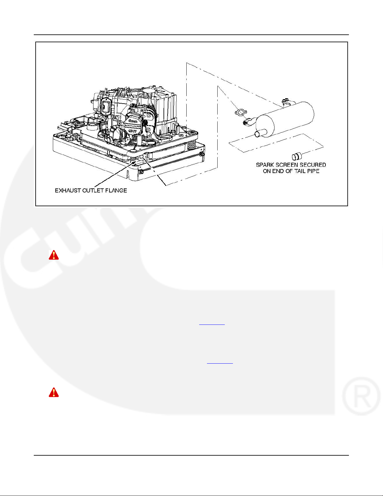
4.2 Muffler—Model HGJAC
Figure 6 illustrates the exhaust outlet flange and a side-mount muffler kit available from Onan.
The muffler must have a USDA (Forest Service) spark arrestor, meet RVIA EGS-1
requirements, be constructed of aluminized steel or material of equivalent corrosion resistance
and be of welded or crimped construction. The spark arrestor may be integral to the muffler or
an add-on.
A genset without a properly installed and maintained spark arresting exhaust system can cause
a forest fire. It is illegal on federal lands. Liability for damage, injury and warranty expense due
to the modification of the exhaust system or to the use of unapproved parts is the responsibility
of the person performing the modification or installing the unapproved parts.
We recommend that you contact an Onan dealer for spark arresting mufflers that meet RVIA
and USDA requirements. Side-mount and bottom-mount muffler kits are available from Onan,
with front or back exhaust outlets. The kits include a USDA (Forest Service) spark screen for
mounting in the end of the tail pipe.
Follow the instructions in the Onan kit when mounting the muffler. See TAIL PIPE regarding
materials, clamps, support, routing and termination. Install the spark screen in accordance with
the instructions in the kit.
14 983-0600 (Issue 10)
Page 21
7-2011 4. Exhaust Connections
FIGURE 6. TYPICAL EXTERNAL MUFFLER KIT INSTALLATION
4.3 Tail Pipe
WARNING: Beginning with Spec J, EPA Phase 3 and CARB Tier 3 product incorporates a
catalyst which leads to subsequent higher exhaust gas temperatures. Due to
higher exhaust gas temperatures, the installer must review and follow all
guidelines for tail pipe installations, shielding and surrounding material
requirements for compatibility.
1. Use 1-3/8 inch ID aluminized steel tubing or equivalent for the tail pipe. (Do not use flexible
pipe. Flexible pipe is not gas tight or durable.)
2. Use U-bolt muffler clamps to connect sections of tail pipe. It is recommended that the
overlapping pipe be slotted as shown in Figure 7.
3. Use automotive-type tail pipe hangers every 2 to 3 feet (0.6 to 0.9 m). Attach the hangers
to steel framework, not to wood or other combustible material.
4. Do not terminate the tail pipe underneath the vehicle. Extend it a minimum of 1 inch (25
mm) beyond the perimeter of the vehicle (Figure 8). Support the end of the tail pipe such
that it cannot be pushed inward and up under the skirt of the vehicle.
5. Do not route the tail pipe underneath the oil drain or cooling air inlet.
WARNING: A hot exhaust tail pipe can ignite oil drain spills causing severe personal
injury or death. Do not route the exhaust tail pipe underneath the oil drain.
6. Do not route the tail pipe closer than 3 inches (76 mm) to combustible material (wood, felt,
cotton, organic fibers, etc.) unless it is insulated or shielded. The temperature rise (above
ambient) on adjacent combustible material must not exceed 117°F (65°C).
7. Do not route the tail pipe near fuel lines or fuel tanks.
983-0600 (Issue 10) 15
Page 22

4. Exhaust Connections 7-2011
8. Do not terminate the tail pipe such that it is closer than 6 inches (153 mm) to any opening
into the vehicle interior (door, window, vent). See Figure 9.
9. Do not connect the genset to the vehicle engine exhaust system.
CAUTION: Interconnecting the engine exhaust systems will allow exhaust condensates and
soot to migrate into the engine that is idle, causing engine damage.
16 983-0600 (Issue 10)
Page 23

7-2011 4. Exhaust Connections
FIGURE 7. EXHAUST TAILPIPE CONNECTIONS
FIGURE 8. TERMINATING EXHAUST TAILPIPE
983-0600 (Issue 10) 17
Page 24

4. Exhaust Connections 7-2011
FIGURE 9. MINIMUM DISTANCES TO OPENINGS
10. Route the tail pipe such that it is not likely to be struck when the vehicle is moving. Keep it
out of the approach and departure angles of the vehicle and above the axle clearance line
(Figure 10).
11. Make sure a tail pipe deflector will not cause excessive back pressure or interfere with
removing a spark arresting screen, if so equipped.
CAUTION: Excessive back pressure can cause loss of performance and engine damage.
FIGURE 10. VEHICLE CLEARANCES
18 983-0600 (Issue 10)
Page 25

5 Fuel Connections
See the Operator's Manual for recommended fuels and Specifications (Chapter 8) for fuel
consumption.
WARNING: Gasoline and Propane are flammable and explosive and can cause severe
personal injury or death — Do not smoke — Keep flames, sparks, pilot lights,
switches, arc-producing equipment and all other ignition sources away from
fuel, fuel components and areas sharing ventilation — Keep an ABC fire
extinguisher handy.
CAUTION: Unauthorized modifications or replacement of fuel, exhaust, air intake or speed
control system components that affect engine emissions are prohibited by law in
California.
5.1 Gasoline—Model HGJAA (EFI)
NOTE: The installer is responsible for meeting all CARB and EPA evaporative
emissions requirements that may be applicable for the fuel system.
Beginning January 1, 2011 all 50 states require evaporative regulation
compliance.
NOTE: Installation instructions for motorized vehicles utilizing existing vehicle fuel
tank.
5.1.1 Remote Fuel Pump Kit
These gensets have an electronic fuel injection system supplied by a remote electric pump.
Install only the pump kit available for use in the make and model of the vehicle in which the
genset is installed. Follow the installation instructions in the pump kit. Fit. (Figure 11) illustrates
the wiring connector for the remote pump.
FIGURE 11. FUEL PUMP KIT
983-0600 (Issue 10) 19
Page 26

5. Fuel Connections 7-2011
5.1.2 Fuel Tank
Do not change or remove the fuel fill tube, fill limiter vent, vapor canister, vapor lines, filler cap
or any other part of the fuel system without the express approval of the vehicle chassis
manufacturer. Modifications must conform with applicable sections of the Code of Federal
Regulations, Titles 40 and 49, and other standards.
The genset and propulsion engine fuel supply and return lines must not be interconnected.
The maximum fuel pump lift is 36 inches (914 mm).
Terminate the genset fuel pickup above the vehicle engine pickup in the supply tank to keep the
genset from running the vehicle out of fuel.
Connect 1/4 inch fuel line from vehicle fuel tank to generator set (Figure 12).
FIGURE 12. FUEL FITTING-LEFT END OF BASE
5.1.3 Fuel Supply Line Pump to Genset
Figure 14 illustrates the wiring connector at the generator set for the remote pump.
Connect the 5/16 inch generator set hose barb to the vapor hose from the carbon canister.
Connect the 1/4 inch generator set hose barb to the fuel supply hose from the fuel tank (Figure
18).
20 983-0600 (Issue 10)
Page 27

7-2011 5. Fuel Connections
FIGURE 13. REMOTE PUMP WIRING CONNECTOR
FIGURE 14. FUEL FITTINGS—LEFT END OF BASE
5.1.4 Vapor and Fuel Return Line Requirements
(Figure 15) illustrates suitable tooling to form tubing ends.
1. Gasoline model HGJAB evaporative (EVAP) requires an additional fuel vapor line from the
carbon canister to the generator set.
2. Gasoline model HGJAA electronic fuel injected (EFI) requires a vapor line from the carbon
canister to the generator set and a return fuel line from the generator set to the fuel tank.
983-0600 (Issue 10) 21
Page 28

5. Fuel Connections 7-2011
FIGURE 15. DOUBLE-FLARE SAE J1231 HOSE BEADS AND STEPLESS EAR CLAMP
5.1.5 Routing Fuel Lines
Route the supply and return lines side-by-side along bulkheads and frame members such that
they are protected. They should be at or above the top of the fuel tank to reduce siphoning if a
line breaks or a hose comes off. The entire length of the fuel lines must be visible for inspection
and accessible for replacement.
Support fuel lines to restrain movement and prevent chaffing or contact with sharp edges,
electrical wiring and hot exhaust parts.
WARNING: Electric arcs can ignite gasoline leading to severe personal injury or death.
Do not run wiring and fuel lines together.
· Requirements for fuel line routing near propulsion engine and generator exhaust.
5.2 Gasoline—Models HGJAB/HGJAC
NOTE: The installer is responsible for meeting all CARB and EPA evaporative
emissions requirements that may be applicable for the fuel system.
Beginning January 1, 2011 all 50 states require evaporative law compliance.
NOTE: Installation instructions for motorized vehicles utilizing existing vehicle fuel
tank.
5.2.1 Fuel Tank
Do not change or remove the fuel fill tube, fill limiter vent, vapor canister, vapor lines, filler cap
or any other part of the fuel system without the express approval of the vehicle chassis
manufacturer. Modifications must conform with applicable sections of the Code of Federal
Regulations, Titles 40 and 49, and other standards.
22 983-0600 (Issue 10)
Page 29

7-2011 5. Fuel Connections
Onan requires a separate fuel pickup tube or a separate fuel tank for the genset. The genset
must never be connected to the fuel supply line of the vehicle engine—either to a highpressure system (pump in tank), which can overpressurize the genset fuel system, or to a
vacuum system (pump on engine), which can cause the genset to starve for fuel. Some vehicle
chassis manufacturers allow connections to the fuel return line on high pressure fuel systems.
Contact the vehicle chassis manufacturer for approval. Fuel line pressure at the point where the
genset is connected must not exceed 1-1/2 psi under any condition.
WARNING: Excessive fuel pressure can flood the genset causing a fire. Genset fuel
supply line pressure must not exceed 1-1/2 psi under any condition.
NOTE: For EFI systems a fuel return line to the supply tank must be provided by the
installer. The generator set and propulsion engine fuel supply and return lines must
not be interconnected.
The EFI fuel pump can pump fuel significantly better than it can draw fuel out of the main tank.
For this reason locate the high pressure EFI pump as close to the tank pickup as possible.
Terminate the genset fuel pickup above the vehicle engine pickup in the supply tank to keep the
genset from running the vehicle out of fuel.
5.2.2 Fuel Lines
Figure 12 illustrates the fuel inlet fitting at the genset.
Carburetor
· Tubing: Use 1/4 inch I.D. (±0.003 inch) welded and drawn Type 304L stainless or AISI
1008-1010 low carbon steel tubing of 0.028 inch minimum wall thickness. The tubing must
meet requirements for 150 psi operating pressure (Ref. ASTM A 539-99) and have
corrosion resistance equal to or better than hot-dipped zinc galvanization.
· Hose Beads: Use suitable tooling to form tubing ends into SAE J1231 Type 1 or Type 3
double-flare hose beads (Figure 15). This is recommended for all tubing and fittings.
· Flexible Hose: Use 1/4 inch I.D. fuel hose that meets applicable standards for evaporative
emissions.
Evaporative
· Tubing: Use 5/16 inch O.D. (±0.003 inch) welded and drawn Type 304L stainless or AISI
1008-1010 low carbon steel tubing of 0.028 inch minimum wall thickness. The tubing must
meet requirements for 150 psi operating pressure (Ref. ASTM A 539-99) and have
corrosion resistance equal to or better than hot-dipped zinc galvanization.
· Hose Beads: Use suitable tooling to form tubing ends into SAE J1231 Type 1 or Type 3
double-flare hose beads (Figure 15). This is required for all tubing and fittings.
· Flexible Hose: Use 5/16 inch I.D. fuel hose that meets SAE J30R9 standards for working
pressure and applicable standards for evaporative emissions.
CAUTION: When connecting fuel hoses, only use soap-free lubricants such as WD-40, which
runs through fuel without leaving residues that can clog fuel jets.
· Hose Clamps: Use stainless steel ear clamps (Figure 15). Onan part number 0503-1951-
11, Oetiker part number 16700011 or equivalent worm screw type clamps are no longer
allowed.
983-0600 (Issue 10) 23
Page 30

5. Fuel Connections 7-2011
5.2.3 Routing Fuel Lines
Route the fuel line along bulkheads and frame members such that it is protected, and at or
above the top of the fuel tank to reduce siphoning if a line breaks or a hose comes off. The
entire length of a fuel line must be visible for inspection and accessible for replacement.
Support fuel lines to restrain movement and prevent chaffing or contact with sharp edges,
electrical wiring and hot exhaust parts.
WARNING: Electric arcs can ignite gasoline leading to severe personal injury or death.
Do not run wiring and fuel lines together.
FIGURE 16. FUEL FITTING—LEFT END OF BASE
5.3 Evaporative system installation
Evaporative generator sets are used in trailers, fifth wheel trailers and other non-motorized
vehicles. This applications require a carbon canister, fuel tank, vapor hose and fuel return lines
depending on generator set.
These instructions cover installation of the generator set fuel evaporative system provided for
compliance with all 50 states EPA regulations for small off-road equipment effective January 1,
2011. The instructions apply to the following evaporative generator set models:
5.5HGJAA-600 RV EFI
5.5HGJAA-1273 RV EFI
7HGJAA-97 RV EFI
5.5HGJAB-6755 RV Carburetor
5.5HGJAB-7103 RV Carburetor
7HGJAB-6756 RV Carburetor
5.5HGJAE-6757 Commercial Mobile Carburetor
24 983-0600 (Issue 10)
Page 31

7-2011 5. Fuel Connections
7HGJAE-6758 Commercial Mobile Carburetor
5.5HGJAD-6759 Commercial Mobile EFI
7HGJAD-6760 Commercial Mobile EFI
Completing the installation of the genset evaporative fuel system is required for all towable or
similar generator set applications where on-board gasoline fuel storage is self-contained in the
trailer equipment.
It is the responsibility of the towable equipment manufacturer OEM to complete the installation
of the evaporative fuel system exactly as specified in the CARB EO & EPA certification for the
Onan product being installed. These requirements are detailed in the procedure below. Any
deviations from this installation procedure will forfeit the emission certification on the fuel system
and transfer engine evaporative emission certification responsibility to the trailer equipment
manufacturer/OEM per CFR 40 Part 1060.
If purchasing a complete or partial fuel system kit or components from a third party fuel system
manufacturer, the requirements of the Onan installation manual shall be met and the system
must be verified by the OEM & fuel system supplier as meeting these requirements before
completing the installation.
Any questions regarding these installation instructions or evaporative emission certification
should be directed to Cummins Power Generation for clarification.
5.3.1 System Components
The evaporative system consists of the fuel tank, carbon canister, generator set and connecting
hoses. Gasoline vapors in the fuel tank accumulate in the carbon canister when the generator
set is not running. They are drawn into the engine combustion chamber and burned while the
generator set is operating.
5.3.2 Fuel Tank
NOTE: The following specifications apply only to evaporative emissions
performance. The installer is also responsible for the selection and
installation of the fuel tank to meet other safety and performance
requirements that may be applicable.
For compliance with evaporative emissions regulations, the fuel tank shall:
1. Be metal.
2. Have a 13 to 35 gallon capacity.
3. Have a permanently tethered cap.
4. Have cap that provides a vapor seal and that audibly signals that the vapor seal has been
established (click or snap).
5. Have a roll-over vent valve with connection for 5/16 inch ID hose. This hose connects to
the carbon canister.
6. Have a fill-neck and an anti-spit-back valve if it is a non top-fill tank.
7. Be constructed to meet the requirements of Section 393.67 (joints, fittings and threads) of
the Federal Motor Carrier Safety Administration Regulations.
983-0600 (Issue 10) 25
Page 32

5. Fuel Connections 7-2011
8. Have connections that meet the requirements of the following SAE standards, when
applicable: J1231 (Formed Tube Ends for Hose Connections and Hose Fittings), J1508
(Hose Clamp Specifications), J2260 (Nonmetallic Fuel System Tubing with One or More
Layers), J2044 (Quick Connector Specification for Liquid Fuel and Vapor/Emissions
Systems), and J2599 (Fuel Filler Pipe Assembly Design Practice to Meet Low Evaporative
Emission Requirements).
5.3.3 Carbon Canister
Use a Delphi carbon canister shown below. No other carbon canisters are acceptable.
Part Number Description Onan Part
17208238 3.1L, 196g working capacity 0159-1755
17208262 3.3L, 233.8g working capacity 0159-1754
Mount the canister in any orientation except hose barb pointing down (Figure 17) in accordance
with its instructions.
Connect the 5/16 inch hose barb (identified by the fuel pump icon) to the hose from the fuel tank
and the adjacent 3/8 inch hose barb to the hose from the generator set. See (Figure 18)
NOTE: Use 5/16 inch hose for vapor lines. Use an SAE J2044 quick connect fuel
fitting on the canister hose barb or use a soap-free lubricant such as WD40
to slip the hoses on the canister hose barbs. Secure the hoses with Oeitiker®
ear-type clamps or equivalent.
To prevent dirt from entering the canister vent when it is mounted in a “dirty" location, connect
the 5/8 inch hose barb to a hose terminated outside the living space of the vehicle at a location
that is not exposed to road splash or dust. Alternatively, secure Onan Part Number 0148-1343
vent filter to the hose barb.
CAUTION: Blockage of the canister vent or vent hose could lead to collapse of system
components due to vacuum.
WARNING: Do not vent the canister (5/8 inch line) into the vehicle or other confined
space where the vapors could accumulate to a flammable level.
Number
26 983-0600 (Issue 10)
Page 33

7-2011 5. Fuel Connections
FIGURE 17. ACCEPTABLE CANISTER MOUNTING ORIENTATIONS
983-0600 (Issue 10) 27
Page 34

5. Fuel Connections 7-2011
FIGURE 18. EVAPORATIVE COMPONENTS OF CARBURETOR SYSTEM
28 983-0600 (Issue 10)
Page 35

7-2011 5. Fuel Connections
5.3.4 Carburetor Fuel System Generator Sets
Connect the 5/16 inch generator set hose barb to the vapor hose from the carbon canister.
Connect the 1/4 inch generator set hose barb to the fuel supply hose from the fuel tank. See
Figure 18.
5.3.5 Fuel Injection (EFI) System Generator Sets
Connect the 5/16 inch generator set hose barb farthest from the corner of the base to the vapor
purge hose from the carbon canister. Connect the other 5/16 inch hose barb to the fuel supply
hose from the fuel pump. Connect the 1/4 inch hose barb to the fuel return hose. See Figure 19
.
983-0600 (Issue 10) 29
Page 36

5. Fuel Connections 7-2011
FIGURE 19. EVAPORATIVE COMPONENTS OF FUEL INJECTION (EFI) SYSTEMS
30 983-0600 (Issue 10)
Page 37

7-2011 5. Fuel Connections
5.3.6 Fuel Hoses
The fuel hoses used inside the generator set are low permeation fuel hoses which meet Federal
50 state standards for gasoline evaporative emissions.
The vapor and liquid hoses connecting the fuel tank to the generator set, the fuel tank to the
carbon canister and the carbon canister to the generator set must also be low permeation fuel
hoses. Low permeation fuel hose is required to meet these requirements for gasoline generator
sets sold in or used for commerce in all 50 states. The following hose materials are acceptable:
· Avon Automotive “Greenbar" (EO# G-05-018) SAE J30R7
· Avon Automotive “Greenbar 1200" (EO# C-U-05-009) SAE J30R12
· Gates 4219D (EO# C-U-06-002) SAE J30R9
· Gates Barricade (EO# Q-09-019)
· Kubota (EO# C-U-05-003) SAE J30R7
· Mark IV Automotive “Gen2" (EO# C-U-05-002) SAE J30R7
· Mark IV Automotive "Fluoroperm" (EO# C-U-07-017) SAE J30R9
· Mark IV Automotive Dayperm" (EO# C-U-06-030) SAE J30R7
· Mark IV Automotive "Dayperm" (EO# G-05-016)
· Mold-Ex Division of SETi, Inc. "SETiFLEX II" (EO# G-05-17A) SAE J30R7
· Parker Hannifin Corp "Super Flex FL-7 series 389XX" (EO# Q-08-013)
· Veyance Technologies Inc. "Goodyear Flexshield" (EO# Q-09-022)
Lubricants used when connecting fuel hoses can leave residues that can clog fuel jets. Only use
“soap-free" lubricants such as WD40.
CAUTION: When connecting fuel hoses, only use soap-free lubricants such as WD40, which
runs through with the fuel without leaving residues that can clog fuel jets.
5.4 Low Pressure Propane Supply (Vapor Withdrawal)
Use the Standard for the Storage and Handling of Liquefied Petroleum Gases (NFPA No. 58) as
a guide for the installation of the propane fuel system. Figure 20 illustrates the fuel fitting and
regulator vent screen.*
WARNING: Propane is flammable and explosive and can cause asphyxiation. NFPA 58,
Section 1.6 requires all persons handling propane to be trained in proper
handling and operating procedures.
The genset must be connected to the vapor withdrawal fitting on the propane tank. The tank
must have a manual shutoff valve and 2-stage pressure regulator. Adjust the regulator to deliver
9 to 13 inches (229 to 330 mm) Water Column (WC) pressure at the genset.
WARNING: High propane supply pressure can cause gas leaks which can lead to fire and
severe personal injury or death. Propane supply pressure must be adjusted
to Specifications by qualified personnel.
Use approved fuel line materials of 3/8-inch I. D. for runs up to 3 feet (0.9 m) and 1/2-inch I. D.
for runs up to 15 feet (4.6 m).
983-0600 (Issue 10) 31
Page 38

5. Fuel Connections 7-2011
Do not connect the genset fuel supply line to any appliance fuel supply line. The genset can
draw fuel away from other appliances and cause a flame out. To prevent the possibility of
flameout, the fuel supply system must be designed to deliver sufficient fuel for normal operation
of the genset and other appliances at the expected temperature conditions. It may be necessary
to use a separate fuel tank for the genset if sufficient fuel cannot be supplied with a single tank
system.
WARNING: The flameout of an unvented propane appliance can lead to explosive
accumulations of gas inside the vehicle and the danger of severe personal
injury or death. Do not connect the genset fuel supply line to any vehicle
appliance supply line.
Gas lines must be routed away from hot exhaust parts and electrical wiring, be supported and
protected to prevent chaffing, kinking and pinching and be accessible throughout for inspection
and replacement.
WARNING: Sparks can ignite propane, leading to severe personal injury or death. Do not
run electrical wiring and fuel lines together.
Upon completing the installation, fill the propane tank and test every joint and fitting in the
propane supply system using an approved method, such as soap bubbles.
WARNING: Testing for gas leaks with a flame can cause a fire or explosion that could
lead to severe personal injury or death. Use approved methods only.
FIGURE 20. FUEL FITTING—LEFT END OF BASE
* - The genset fuel regulator is vented to this location to prevent variations in compartment air
pressure from affecting fueling and to vent propane outside the genset compartment if the
regulator diaphragm develops a leak.
32 983-0600 (Issue 10)
Page 39

7-2011 5. Fuel Connections
5.5 High Pressure Propane Supply (Liquid Withdrawal)
The Standard for the Storage and Handling of Liquefied Petroleum Gases (NFPA No. 58)
should be used as a guide for the installation of the propane fuel system. Figure 21 illustrates
the genset fuel fitting and Figure 22 the fuel handling parts of a typical high pressure propanefuel supply system.
WARNING: Propane is flammable and explosive and can cause asphyxiation. NFPA 58,
Section 1.6 requires all persons handling propane to be trained in proper
handling and operating procedures.
Connect the genset to the propane supply line with flexible hose that is non-conductive between
its end fittings so that the fuel line cannot become an alternative path for cranking currents. The
hose must be Listed for 350 psi working pressure and LP-Gas or Propane.
Gas lines must be routed away from hot exhaust parts and electrical wiring, be supported and
protected to prevent chaffing, kinking and pinching and be accessible throughout for inspection
and replacement.
WARNING: Sparks can ignite propane, leading to severe personal injury or death. Do not
run electrical wiring and fuel lines together
Upon completing the installation, fill the propane tank and test every joint and fitting in the
propane supply system using an approved method, such as soap bubbles.
WARNING: Testing for gas leaks with a flame can cause a fire or explosion that could
lead to severe personal injury or death. Use approved methods only.
FIGURE 21. FUEL FITTING—LEFT END OF BASE
983-0600 (Issue 10) 33
Page 40

5. Fuel Connections 7-2011
FIGURE 22. TYPICAL HIGH PRESSURE PROPANE SUPPLY SYSTEM (LIQUID WITHDRAWAL)
34 983-0600 (Issue 10)
Page 41

6 Electrical Connections
To prevent accidental starting of the genset during installation, do not connect the battery cables
at the battery until so instructed in Section 7.3.
WARNING: Accidental starting of the genset can cause severe personal injury or death.
Do not connect the starting battery until so instructed in STARTUP.
6.1 AC Power Output Connections
The generator set is equipped with circuit breakers (30/30 or 30/20) and 120 inch (3 m) long,
30A (10 AWG) leads for AC power output, which exit through a rain-tight 1/2 inch trade size
conduit connector (Figure 23). These leads can be terminated at the Main AC Distribution
Panel where individual breakers can be provided for vehicle/trailer AC loads. If longer AC cable
is required or code stipulates, a 4 x 4 inch junction box is mounted near the generator set.
When extending this cable use the proper size wire for amperage and insulation temperature
rated wire (typically 10 AWG) to the Main AC Distribution pane. For typical connections see
Figure 24 and for internal genset wiring see Bad link: c:/topleafserver/temp/gmyhr8mx/en-
us/.new_components/generator_set/fromcomponetsfolder_manuals/a035d005_i1/topic/topwiringdiagrams.xml.
FIGURE 23. OUTPUT CONDUIT CONNECTOR-BOTTOM, LEFT END OF BASE
6.1.1 Wiring Methods
Follow the National Electrical Code, especially noting the following:
1. Have a qualified electrician supervise and inspect the installation of all AC wiring.
2. Install vibration-proof switches and controls that won't open and close circuits when the
vehicle is in motion.
983-0600 (Issue 10) 35
Page 42

6. Electrical Connections 7-2011
3. Provide ground fault circuit interrupters (GFCIs) for all convenience power receptacles.
4. Route AC wiring, remote control wiring and fuel lines separately.
5. Seal all conduit openings into the vehicle interior to keep out exhaust gas. Apply silicone
rubber or equivalent sealant inside and outside each conduit connector. (Flexible conduit is
not vapor-tight and will allow exhaust gas to enter along the wires if not sealed.)
WARNING: EXHAUST GAS IS DEADLY! Seal all wiring openings into the vehicle interior
to keep out exhaust gas.
6. Bond the genset and all connected AC and DC equipment and controls to a common
grounding point in accordance with applicable codes.
WARNING: Faulty grounding can lead to fire and electrocution, resulting in severe
personal injury or death. Grounding must be in accordance with applicable
codes.
6.1.2 Connecting Shore Power
A vehicle with provisions for connecting shore power (utility) must have an approved device to
keep the genset and utility from being interconnected. See Figure 24 for typical connections.
WARNING: Backfeed to shore power (utility) can cause electrocution or damage to
equipment. Use an approved device to prevent the genset from being
interconnected with shore power.
36 983-0600 (Issue 10)
Page 43

7-2011 6. Electrical Connections
FIGURE 24. TYPICAL CONNECTIONS WITH TRANSFER SWITCH AND UTILITY
6.2 Remote Control Connections
The genset has an 8-pin connector for remote control connections (Figure 25). Wiring
harnesses in several lengths are available separately for connections between the genset and a
remote control panel. For internal genset control wiring see Bad link:
c:/topleafserver/temp/gmyhr8mx/enus/.new_components/generator_set/fromcomponetsfolder_manuals/a035d005_i1/topic/topwiringdiagrams.xml.
983-0600 (Issue 10) 37
Page 44

6. Electrical Connections 7-2011
The 2-pin connector on Model HJGAA EFI gensets is for the remote fuel pump. See Section
5.1.1 .
Onan offers a variety of three remote control panels, as follows:
· Remote start/stop switch with status indicator light only (Figure 26).
· Remote start/stop switch with status indicator light and hour meter (Figure 27).
· Remote start/stop switch with status indicator light and DC voltmeter (Figure 28).
To make connections to a remote control panel:
1. Push the genset remote control connector through the entrance hole in the side of the
genset housing and snap it together with the remote wiring harness connector mate.
2. Refer to Figure 29 to fabricate the remote control panel and/or wiring harness when not
using the accessories available from Onan. Mark the remote control end of each lead to
identify the connector pin number at the genset. Use insulated 18 AWG copper conductors
for distances up to 30 feet (9 meters) and heavier gauge conductors for greater distances.
Protect the wiring with full-length flexible sheathing.
3. Route control leads separately from AC power leads to reduce the possibility of erratic
operation due to false induced signals.
4. Seal the opening where the leads enter the vehicle interior with silicone rubber or
equivalent sealant to keep out exhaust gas.
WARNING: EXHAUST GAS IS DEADLY! Seal all wiring openings into the vehicle interior
to keep out exhaust gas.
FIGURE 25. REMOTE CONNECTORS
38 983-0600 (Issue 10)
Page 45

7-2011 6. Electrical Connections
FIGURE 26. REMOTE SWITCH
FIGURE 27. REMOTE SWITCH / HOUR METER
FIGURE 28. REMOTE SWITCH / DC VOLTMETER
983-0600 (Issue 10) 39
Page 46

6. Electrical Connections 7-2011
FIGURE 29. SCHEMATIC OF TYPICAL REMOTE CONTROL CONNECTIONS
6.3 Battery Connections
To prevent accidental starting of the genset during installation, do not connect the battery cables
at the battery until so instructed in Section 7.3 .
WARNING: Accidental starting of the genset can cause severe personal injury or death.
Do not connect the starting battery until so instructed in STARTUP.
The genset has a 12 VDC, negative-ground engine control and cranking system. See Chapter 8
for the requirements for cranking batteries.
6.3.1 Battery Compartment
Batteries must be mounted in a compartment separate from that of the genset and away from
spark-producing equipment including the generator set. A compartment must have openings of
at least 1.7 square inches (11 square centimeters) at the top and bottom for ventilation of
battery gasses. It should be located such that spills and leaks will not drip acid on fuel lines,
wiring and other equipment that could be damaged.
WARNING: Arcing can ignite the explosive hydrogen gas given off by the battery,
causing severe personal injury. The battery compartment must be ventilated
and must isolate the battery from spark-producing equipment.
40 983-0600 (Issue 10)
Page 47

7-2011 6. Electrical Connections
6.3.2 Battery Cables
Size battery cables according to Table 2. The current path between the genset and the negative
(-) battery terminal must also be able to carry full cranking current without causing excessive
voltage drop. It is highly recommended that a full-length cable be used to connect the genset to
the negative (-) battery terminal (Figure 30). Note also that codes may require a bonding
conductor between the genset and vehicle frame and between the battery and vehicle frame.
If the vehicle frame is used as the path between the negative (-) battery terminal and the genset
(Figure 31), all frame members in the path of battery cranking currents must have substantial
crossections. Riveted or bolted frame joints must not be used or it will cause corrosive
conditions. A cable sized according to Table 2 must be used to connect the frame to the
designated negative (-) terminal on the genset (Figure 31). The genset mounting bolts are
not considered adequate means for bonding the genset to the vehicle frame, either for
the purpose of carrying cranking currents or for complying with requirements for
genset/system grounding.
TABLE 2. BATTERY CABLE SIZES FOR TEMPERATURES DOWN TO -20° F (-29° C)
TOTAL CABLE LENGTH* FEET (METERS) CABLE SIZE AWG
0 to 45 (0 to 13.7) 2
46 to 60 (14 to 18.3) 0
61 to 80 (18.6 to 24.4) 00
* - *Battery cable lengths are total lengths from the battery to the generator back to the battery and when using a total
of 1000CCA (Cold Cranking Amps).
FIGURE 30. FULL-LENGTH CABLE FROM BATTERY NEGATIVE (-) TERMINAL
FIGURE 31. VEHICLE FRAME AS PATH FROM BATTERY NEGATIVE (-) TERMINAL
983-0600 (Issue 10) 41
Page 48

6. Electrical Connections 7-2011
Route battery cables away from fuel lines and hot engine exhaust components. Battery cables
should be accessible for inspection and replacement, protected from damage and secured to
prevent chafing due to vibration.
WARNING: Routing battery cables with fuel lines can lead to fire and severe personal
injury or death. Keep battery cables away from fuel lines.
6.3.3 Battery Cable Connections at Genset
Terminate the battery cables with ring terminals sized for 5/16 inch screws and connect them to
the genset as shown in Figure 32 and Figure 33. Secure the insulating boot on the positive (+)
terminal and tie it to the battery cable with the tie-wrap in the bag with the manuals.
Torque the positive (+) cable terminal to 4.5 lb-ft (6 N-m).
Torque the negative (-) cable screw to 8 lb-ft (11 N-m).
6.3.4 Genset (Equipment) Grounding Screw
When required (see Figure 30) connect the genset grounding screw (Figure 32) to the vehicle
frame with a No. 8 AWG or larger stranded cable having a ring terminal sized for a 3/8 inch
screw.
Torque the grounding screw to 8 lb-ft (11 N-m).
FIGURE 32. POSITIVE (+) CABLE TERMINAL & GENSET GROUNDING SCREW
42 983-0600 (Issue 10)
Page 49

7-2011 6. Electrical Connections
FIGURE 33. NEGATIVE (-) CABLE SCREW
983-0600 (Issue 10) 43
Page 50

6. Electrical Connections 7-2011
This page is intentionally blank.
44 983-0600 (Issue 10)
Page 51

7 Installation Review and Startup
7.1 Hot Air Recirculation Test
A representative installation of the genset must be tested to determine that the genset will not
overheat due to recirculation of hot air back into the genset.
7.1.1 Test Method
1. Complete a representative installation.
2. Set up a load bank to run the genset at rated full-load or apply the maximum load
available.
3. Conduct the test at a location where the ambient air temperature will remain between 60° F
and 100° F (16° C and 38° C).
WARNING: EXHAUST GAS IS DEADLY! Do not operate the genset when the vehicle is
parked indoors or where exhaust can accumulate.
4. Measure temperatures with thermocouples not heavier than No. 24 AWG (0.21 mm2).
a. Measure genset inlet air temperature with one thermocouple tied in the middle of the
inlet air grille (Figure 34).
b. Measure ambient air temperature with a shielded thermocouple within 4 feet (1.2
5. Close all compartment doors and run the genset at full-load for at least an hour. Record
temperatures at 10 minute intervals until they stabilize. Temperature is considered stable
when there is no change in three consecutive readings. Table 3 illustrates how the data
can be arranged for recording and analysis.
THERMOCOUPLE
LOCATION
AMBIENT AIR
INLET AIR
meters) of the genset and at approximately the same height. Make sure the
thermocouple will not be affected by warm air discharged from the genset or by
sunlight. Use 2 inch diameter white PVC piping at least 6 inches long as a
thermocouple shield.
TABLE 3. TEMPERATURE DATA
TEMPERATURE C° (F°)
Time Of Reading
983-0600 (Issue 10) 45
Page 52

7. Installation Review and Startup 7-2011
7.1.2 Test Requirement
Run the generator set with the most load available for an hour or so until temperature readings
stabilize (each reading is plus or minus 3 degrees) not rising or falling. The best scenario is
temperature ambient and temperature inlet are identical. The difference in readings should not
exceed 25° F (14° C). A rise in inlet air temperature indicates hot air recirculation. If the rise
exceeds the requirement, steps must be taken to reduce recirculation to an acceptable level.
Review Section 3.4 .
CAUTION: High ambient operating temperatures could reduce maximum genset power output
if the air temperature rise measured in this test is on the high end of the acceptable
range.
FIGURE 34. THERMOCOUPLE LOCATIONS FOR HOT AIR RECIRCULATION TEST
7.2 Installation Review
Before starting the genset inspect the installation and check (ü) each of the following questions
if it can be answered “YES". If an item cannot be checked, provision must be made to satisfy
the requirement.
· □ Is the control panel on the genset easily accessible for starting and stopping the genset
and resetting the circuit breaker?
· □ Is there easy access for checking and adding engine oil, replacing the spark plugs and
changing the air filter?
· □ Is the genset securely bolted in place?
· □ Are all specified clearances provided?
· □ Are the air inlet and outlet openings free of obstructions?
· □ Is there access for draining engine oil?
· □ Are all tail pipe connections tight and all hangers and support straps secure?
· □ Does the tail pipe terminate at least 1 inch (25 mm) beyond the perimeter of the vehicle
and at least 6 inches (153 mm) away from any opening into the vehicle?
46 983-0600 (Issue 10)
Page 53

7-2011 7. Installation Review and Startup
· □ Is the genset located outside the vehicle interior or separated by approved vapor- and
fire-resistive materials?
· □ Are all openings into the vehicle, such as for AC wiring, sealed to keep out engine
exhaust? Are AC conduit connectors sealed inside and outside?
· □ Have all AC connections been inspected and approved?
· □ Has a properly sized battery been installed in a ventilated compartment isolated from the
genset?
· □ Have properly sized battery cables been installed and secured at sufficient intervals to
prevent chaffing and contact with sharp edges, fuel lines and hot exhaust parts?
· □ Are all fuel connections tight?
· □ Have the fuel lines been secured at sufficiently close intervals to prevent chaffing and
contact with sharp edges, electrical wiring and hot exhaust parts?
· □ Fuel Injected Models -Has the fuel pump been installed in accordance with the
instructions in the kit? Has a fuel return line been provided?
· □ Has the HOT AIR RECIRCULATION TEST been conducted on a representative
installation with acceptable results?
7.3 Startup
WARNING: EXHAUST GAS IS DEADLY! Do not operate the genset when the vehicle is
When all the items on the Installation Review check list have been checked, connect the battery
cables to the battery, positive (+) cable first.
WARNING: Batteries give off explosive gases that can cause severe personal injury —
Read the Operator's Manual and perform the maintenance and pre-start checks
instructed.Check the oil level and fill as necessary.
Recheck all fuel connections for tightness. On gasoline models check for leaks by priming the
fuel system in accordance with the genset Operator's Manual. Fix all leaks before starting the
genset.
WARNING: Gasoline is flammable and explosive and can cause severe personal injury or
Start and operate the genset, following all the instructions and safety precautions in the
Operator's Manual. Check for fuel and exhaust leaks and unusual noises while the genset is
running under full and intermediate loads. Do not place the genset in service until all fuel and
exhaust leaks have been fixed and operation is satisfactory.
parked indoors or where exhaust can accumulate.
Do not smoke — Keep flames, sparks, pilot lights, switches, arc-producing
equipment and all other ignition sources away.
death. Stop priming immediately if you smell gasoline or see fuel leaking.
Clean up spilled fuel and ventilate the area before starting the genset or
vehicle.
983-0600 (Issue 10) 47
Page 54

7. Installation Review and Startup 7-2011
This page is intentionally blank.
48 983-0600 (Issue 10)
Page 55

8 Specifications
GASOLINE MODELS
7.0 HGJAA 7.0 HGJAB 5.5 HGJAA 5.5 HGJAB
GENERATOR: 2-Pole Revolving Field, 2-Bearing, Self-Excited, 1-Phase, Vertical Shaft, Capped Digital Voltage
Regulation
Power 7000 watts 5500 watts
Frequency 60 Hertz 60 Hertz
Voltage 120 volts 120 volts
Current 58.3 amp 45.8 amp
Speed 3600 rpm 3600 rpm
FUEL CONSUMPTION:
No load 0.43 gph (1.6 l/h) 0.43 gph (1.6 l/h) 0.34 gph (1.3 l/h) 0.35 gph (1.3 l/h)
Half load 0.70 gph (2.7 l/h) 0.73 gph (2.8 l/h) 0.58 gph (2.2 l/h) 0.60 gph (2.3 l/h)
Full load 1.13 gph (4.3 l/h) 1.22 gph (4.6 l/h) 0.89 gph (3.4 l/h) 0.95 gph (3.6 l/h)
ENGINE: Air-Cooled, 4-Cycle Spark-Ignited, OHV, 90° V Twin Cyl, Vertical Shaft
Fueling Method SFI
Governor Digital Mechanical Digital Mechanical
Speed 2880 rpm 2400 rpm
Bore 3.15 in (80 mm) 3.15 in (80 mm)
Stroke 2.56 in (65 mm) 2.56 in (65 mm)
Displacement 39.8 in3(653 cc) 39.8 in3(653 cc)
Comp. Ratio 8.0 : 1 8.0 : 1
Oil Capacity 2.0 quart (1.8 l) 2.0 quart (1.8 l)
Valve Lash (Cold) 0.004 in (0.10 mm), Intake & Exhaust 0.004 in (0.10 mm), Intake & Exhaust
Spark Plug 18-25 lbs-ft (23-32 N-m) 18-25 lbs-ft (23-32 N-m)
Ignition Timing 20° BTDC, non-adjustable magneto 20° BTDC, non-adjustable magneto
Magneto Air Gap 0.012 in (0.3 mm) 0.012 in (0.3 mm)
Spark Plug Gap 0.025 in (6-7 mm) 0.025 in (6-7 mm)
DC SYSTEM:
Battery Voltage 12 volts 12 volts
Min. Battery CCA 450 @ 0° F (-18° C) 450 @ 0° F (-18° C)
INSTALLATION:
Exhaust O. D. 1-1/4 in 1-1/4 in
Max. Exhaust Back
Pressure
Fuel Supply Connection
Fuel Return Connection - -
5/16 in. SAE J1231 1/4 in. SAE J1231 5/16 in. SAE J1231 1/4 in. SAE J1231
1/4 in. SAE J1231 1/4 in. SAE J1231
1
- - - -
Type 1 Type 1 Type 1 Type 1
Type 1 Type 1
Carburetor SFI
1
Carburetor
983-0600 (Issue 10) 49
Page 56

8. Specifications 7-2011
GASOLINE MODELS
7.0 HGJAA 7.0 HGJAB 5.5 HGJAA 5.5 HGJAB
Noise dB(A)
2
66 67 66 67
Weight 290 lb (132 Kg) 290 lb (132 Kg) 279 lb (127 Kg) 279 lb (127 Kg)
Compartment (H x D x
3
W)
HGJAA/HGJAB: 17.2 in x 23.2 in x 34.6 in (438 mm x 589 mm x 879 mm)
1. Sequential Multiport Fuel Injection
2. Measurements @ 10 ft (3 m) in a typical RV installation, under an 4 kW load.
3. With 1/2 in. clearances. See the Installation Manual for additional considerations when sizing the genset
compartment.
LPG MODELS
6.5 HGJAA 6.5 HGJAB 5.5 HGJAA 5.5 HGJAB
GENERATOR: 2-Pole Revolving Field, 2-Bearing, Self-Excited, 1-Phase, Vertical Shaft, Capped Digital Voltage
Regulation
Power 6500 watts 5500 watts
Frequency 60 Hertz 60 Hertz
Voltage 120 volts 120 volts
Current 54.2 amp 45.8 amp
Speed 3600 rpm 3600 rpm
FUEL CONSUMPTION:
No load 2.2 lbs/h (1.0 kg/h) 2.2 lbs/h (1.0 kg/h) 1.8 lbs/h (0.8 kg/h) 1.8 lbs/h (0.8 kg/h)
Half load 3.9 lbs/h (1.8 kg/h) 3.9 lbs/h (1.8 kg/h) 3.3 lbs/h (1.5 kg/h) 3.3 lbs/h (1.5 kg/h)
Full load 5.3 lbs/h (2.4 kg/h) 5.3 lbs/h (2.4 kg/h) 4.6 lbs/h (2.1 kg/h) 4.6 lbs/h (2.1 kg/h)
ENGINE: Air-Cooled, 4-Cycle Spark-Ignited, OHV, 90° V Twin Cyl, Vertical Shaft
Fueling Method Air/Fuel Mixer Air/Fuel Mixer
Governor Mechanical Mechanical
Speed 2880 rpm 2400 rpm
Bore 3.15 in (80 mm) 3.15 in (80 mm)
Stroke 2.56 in (65 mm) 2.56 in (65 mm)
Displacement 39.8 in3(653 cc) 39.8 in3(653 cc)
Comp. Ratio 8.0 : 1 8.0 : 1
Oil Capacity 2.0 quart (1.8 l) 2.0 quart (1.8 l)
Valve Lash
(Cold)
0.004 in (0.10 mm), Intake & Exhaust 0.004 in (0.10 mm), Intake & Exhaust
Spark Plug 18-25 lbs-ft (23-32 N-m) 18-25 lbs-ft (23-32 N-m)
Ignition Timing 20° BTDC, non-adjustable magneto 20° BTDC, non-adjustable magneto
Magneto Air Gap 0.012 in (0.3 mm) 0.012 in (0.3 mm)
Spark Plug Gap 0.025 in (6-7 mm) 0.025 in (6-7 mm)
DC SYSTEM:
Battery Voltage 12 volts 12 volts
50 983-0600 (Issue 10)
Page 57

7-2011 8. Specifications
LPG MODELS
6.5 HGJAA 6.5 HGJAB 5.5 HGJAA 5.5 HGJAB
Min. Battery CCA 450 @ 0° F (-18° C) 450 @ 0° F (-18° C)
INSTALLATION:
Exhaust O. D. 1-1/4 in 1-1/4 in
LPG Vapor:
Connection 3/8-18 NPTF 9-13 in (228-330 mm) WC 3/8-18 NPTF 9-13 in (228-330 mm) WC
Pressure
LPG Liquid:
Connection 1/4-18 NPTF Tank Pressure 1/4-18 NPTF Tank Pressure
Pressure
Noise dB(A)
1
66 67 66 67
Weight 290 lb (132 Kg) 290 lb (132 Kg) 279 lb (127 Kg) 279 lb (127 Kg)
Compartment (H
x D x W)
2
HGJAA/HGJAB: 17.2 in x 23.2 in x 34.6 in (438 mm x 589 mm x 879 mm)
1. Measurements @ 10 ft (3 m) in a typical RV installation, under an 4 kW load.
2. With 1/2 in. clearances. See the Installation Manual for additional considerations when sizing the genset
compartment.
983-0600 (Issue 10) 51
Page 58

8. Specifications 7-2011
This page is intentionally blank.
52 983-0600 (Issue 10)
Page 59

Appendix A. Wiring Diagrams
Table of Contents
WIRING DIAGRAMS .............................................................................................................. 55
Figure 35. Wiring Diagram 611-1272 - HGJAA .......................................................................................... 55
Figure 36. Wiring Diagram 611-1271 - HGJAB/HGJAC ............................................................................. 56
983-0600 (Issue 10) 53
Page 60

Appendix A. Wiring Diagrams 7-2011
This page is intentionally blank.
54 983-0600 (Issue 10)
Page 61

7-2011 Appendix A. Wiring Diagrams
Wiring Diagrams
FIGURE 35. WIRING DIAGRAM 611-1272 - HGJAA
983-0600 (Issue 10) 55
Page 62

Appendix A. Wiring Diagrams 7-2011
FIGURE 36. WIRING DIAGRAM 611-1271 - HGJAB/HGJAC
56 983-0600 (Issue 10)
Page 63

Appendix B. Outline Drawings
Table of Contents
OUTLINE DRAWINGS ............................................................................................................ 59
Figure 37. Outline Drawing 500-3234 - HGJAA/HGJAB ............................................................................ 59
Figure 38. Outline Drawing 500-3235 - HGJAC ......................................................................................... 60
983-0600 (Issue 10) 57
Page 64

Appendix B. Outline Drawings 7-2011
This page is intentionally blank.
58 983-0600 (Issue 10)
Page 65

7-2011 Appendix B. Outline Drawings
Outline Drawings
FIGURE 37. OUTLINE DRAWING 500-3234 - HGJAA/HGJAB
983-0600 (Issue 10) 59
Page 66

Appendix B. Outline Drawings 7-2011
FIGURE 38. OUTLINE DRAWING 500-3235 - HGJAC
60 983-0600 (Issue 10)
Page 67

Page 68

Cummins Power Generation
1400 73rd Ave. NE
Minneapolis, MN 55432 USA
Phone 1 763 574 5000
Toll-free 1 800 888 6626
Fax 1 763 574 5298
Copyright © 2011 Cummins Power Generation, Inc. All rights reserved.
Cummins, the "C" logo, and "Performance you rely on." are trademarks of
Cummins Inc.
 Loading...