

Page 1

Installation Manual
Commercial Mobile Generator Set
HDKBB (Spec A−J)
HDKBC (Spec D−J)
English
Original Instructions 10-2016 981−0650 (Issue 9)
Page 2

California
Proposition 65 Warning
Diesel engine exhaust and some of its constituents are known
to the State of California to cause cancer, birth defects, and
other reproductive harm.
Page 3

Table of Contents
TABLE OF CONTENTS II . . . . . . . . . . . . . . . . . . . . . . . . . . . . . . . . . . . . . . . . . . . . . . . . . . . . .
SAFETY PRECAUTIONS 1 . . . . . . . . . . . . . . . . . . . . . . . . . . . . . . . . . . . . . . . . . . . . . . . . . . .
INTRODUCTION 9 . . . . . . . . . . . . . . . . . . . . . . . . . . . . . . . . . . . . . . . . . . . . . . . . . . . . . . . . . . .
About this Manual 9 . . . . . . . . . . . . . . . . . . . . . . . . . . . . . . . . . . . . . . . . . . . . . . . . . . . . . .
Outline Drawings 9 . . . . . . . . . . . . . . . . . . . . . . . . . . . . . . . . . . . . . . . . . . . . . . . . . . . . . . .
Installation Codes and Standards for Safety 10 . . . . . . . . . . . . . . . . . . . . . . . . . . . . . . . .
Noise 10 . . . . . . . . . . . . . . . . . . . . . . . . . . . . . . . . . . . . . . . . . . . . . . . . . . . . . . . . . . . . . . . . .
Electromagnetic compatibility 10 . . . . . . . . . . . . . . . . . . . . . . . . . . . . . . . . . . . . . . . . . . . . .
MOUNTING, LOCATION AND VENTILATION 11 . . . . . . . . . . . . . . . . . . . . . . . . . . . . . . . . . .
Mounting 11 . . . . . . . . . . . . . . . . . . . . . . . . . . . . . . . . . . . . . . . . . . . . . . . . . . . . . . . . . . . . . .
Location 11 . . . . . . . . . . . . . . . . . . . . . . . . . . . . . . . . . . . . . . . . . . . . . . . . . . . . . . . . . . . . . . .
Ventilation 12 . . . . . . . . . . . . . . . . . . . . . . . . . . . . . . . . . . . . . . . . . . . . . . . . . . . . . . . . . . . . .
EXHAUST CONNECTIONS 13 . . . . . . . . . . . . . . . . . . . . . . . . . . . . . . . . . . . . . . . . . . . . . . . . . .
Muffler 13 . . . . . . . . . . . . . . . . . . . . . . . . . . . . . . . . . . . . . . . . . . . . . . . . . . . . . . . . . . . . . . . .
Tailpipe 14 . . . . . . . . . . . . . . . . . . . . . . . . . . . . . . . . . . . . . . . . . . . . . . . . . . . . . . . . . . . . . . . .
FUEL CONNECTIONS 17 . . . . . . . . . . . . . . . . . . . . . . . . . . . . . . . . . . . . . . . . . . . . . . . . . . . . . .
Bio−diesel Fuels B5 − B20 18 . . . . . . . . . . . . . . . . . . . . . . . . . . . . . . . . . . . . . . . . . . . . . . .
ELECTRICAL CONNECTIONS 21 . . . . . . . . . . . . . . . . . . . . . . . . . . . . . . . . . . . . . . . . . . . . . .
AC Power Connections 21 . . . . . . . . . . . . . . . . . . . . . . . . . . . . . . . . . . . . . . . . . . . . . . . . . .
Remote Control Connections 23 . . . . . . . . . . . . . . . . . . . . . . . . . . . . . . . . . . . . . . . . . . . . .
Battery Connections 23 . . . . . . . . . . . . . . . . . . . . . . . . . . . . . . . . . . . . . . . . . . . . . . . . . . . .
INSTALLATION REVIEW AND STARTUP 27 . . . . . . . . . . . . . . . . . . . . . . . . . . . . . . . . . . . . .
Hot Air Recirculation Test 27 . . . . . . . . . . . . . . . . . . . . . . . . . . . . . . . . . . . . . . . . . . . . . . . .
Installation Review 28 . . . . . . . . . . . . . . . . . . . . . . . . . . . . . . . . . . . . . . . . . . . . . . . . . . . . . .
Startup 28 . . . . . . . . . . . . . . . . . . . . . . . . . . . . . . . . . . . . . . . . . . . . . . . . . . . . . . . . . . . . . . . .
SPECIFICATIONS 29 . . . . . . . . . . . . . . . . . . . . . . . . . . . . . . . . . . . . . . . . . . . . . . . . . . . . . . . . . .
Figure 15. Outline Drawing—Sheet 1 31 . . . . . . . . . . . . . . . . . . . . . . . . . . . . . . . . . . . . . .
Figure 16. Outline Drawing—Sheet 2 31 . . . . . . . . . . . . . . . . . . . . . . . . . . . . . . . . . . . . . .
Figure 17. Wiring Diagram—Sheet 1 32 . . . . . . . . . . . . . . . . . . . . . . . . . . . . . . . . . . . . . .
Figure 18. Wiring Diagram—Sheet 2 33 . . . . . . . . . . . . . . . . . . . . . . . . . . . . . . . . . . . . . .
Copyright 2016 Cummins Inc.
i
Page 4

This Page Intentionally Left Blank.
ii
Copyright 2016 Cummins Inc.
Page 5

SAFETY PRECAUTIONS
Thoroughly read the OPERAT OR’S MANUAL before operating the genset. Safe operation and top
performance can only be obtained when equipment is properly operated and maintained.
Only trained and experienced service personnel
with knowledge of fuels, electricity , and machinery hazards shall remove dismantle and dispose
of the generator set. See service manual.
Some generator set installation procedures
present hazards that can result in severe personal injury or death. Only trained and experienced
personnel with knowledge of fuels, electricity,
and machinery hazards should perform generator set installation procedures.
The following symbols in this manual alert you to potential hazards to the operator, service person and
equipment.
Used to alert you to a lethal hazard
against which you must take steps to prevent severe personal injury or death, as when you are in
the vicinity of High Voltage equipment.
WARNING
safe practice that can result in severe personal
injury or death.
CAUTION
safe practice that can result in personal injury or
equipment damage.
Electricity, fuel, exhaust, moving parts and batteries
present hazards which can result in severe personal
injury or death.
Used to alert you to a hazard or un-
Used to alert you to a hazard or un-
ENGINE EXHAUST IS DEADLY
Inspect for exhaust leaks at every startup and af-
ter every eight hours of running.
Prior to every startup and after every eight hours
of running, all carbon monoxide detectors must
be tested and confirmed to be working in accordance with the manufacturer’s instructions or
owners manual.
Learn the symptoms of carbon monoxide poi-
soning in the genset Operator’s Manual.
Never occupy the vehicle while the genset is
running unless the vehicle is equipped with a
working carbon monoxide detector.
Do not operate the genset when the vehicle is
parked in a confined space, such as a garage.
Disable the automatic genset starting feature
(AGS) of an inverter-charger or other automatic
starting device before storing the vehicle or
parking it in a garage or other confined space.
The exhaust system must be installed in accor-
dance with the genset Installation Manual.
Engine cooling air must not be used for heating
the vehicle.
GENERATOR VOLTAGE IS DEADLY
Disable the automatic genset starting feature
(AGS) of an inverter-charger or other automatic
starting device before servicing the genset.
Generator electrical output connections must be
made by a trained and experienced electrician
in accordance with applicable codes.
WARNING
and shore power can lead to electrocution of utility line workers, equipment damage and fire. Use
an approved switching device to prevent interconnections.
Use caution when working on live electrical
equipment. Remove jewelry, make sure clothing
and shoes are dry, stand on a dry wooden platform or rubber insulating mat and use tools with
insulated handles.
Interconnecting the generator set
DIESEL FUEL IS COMBUSTIBLE
Do not smoke or turn electrical switches ON or
OFF where fuel fumes are present or in areas
sharing ventilation with fuel tanks or equipment.
Keep flames, sparks, pilot lights, arc-producing
equipment and all other sources of ignition well
away.
Fuel lines must be secured, free of leaks and
separated or shielded from electrical wiring.
MOVING PARTS CAN CAUSE SEVERE
PERSONAL INJURY OR DEATH
Disable the automatic genset starting feature
(AGS) of an inverter-charger or other automatic
starting device before servicing the genset.
Copyright 2016 Cummins Inc.
1
Page 6

Do not wear loose clothing or jewelry near mov-
ing parts such as PTO shafts, fans, belts and
pulleys.
Do not work on the genset when mentally or
physically fatigued or after consuming alcohol or
drugs.
Keep hands away from moving parts.
Keep guards in place over fans, belts, pulleys,
and other moving parts.
BATTERY GAS IS EXPLOSIVE
Wear splash−proof safety glasses.
Do not smoke or permit flames or sparks to oc-
cur near the battery at any time.
To reduce arcing when disconnecting or recon-
necting battery cables, always disconnect the
negative (−) battery cable first and reconnect it
last.
FLAMMABLE VAPOR CAN CAUSE A
DIESEL ENGINE TO OVERSPEED
WARNING
genset where a flammable vapor environment
can be created by fuel spill, leak, etc.
Flammable vapor can cause a diesel engine to overspeed and become difficult to stop, resulting in possible fire, explosion, severe personal injury and
death. The owners and operators of the genset are
solely responsible for operating the genset safely.
Do not operate a diesel-powered
GENERAL PRECAUTIONS
Keep children away from the genset.
Do not use evaporative starting fluids. They are
highly explosive.
To prevent accidental or remote starting while
working on the genset, disconnect the negative (−) battery cable at the battery.
Let the engine cool down before removing the
coolant pressure cap or opening the coolant
drain. Hot coolant under pressure can spray out
and cause severe burns.
Used engine oil has been identified by some
U. S. state and federal agencies as causing cancer or reproductive toxicity. Do not ingest, inhale, or contact used oil or its vapors.
Ethylene glycol, used as engine antifreeze, is
toxic to humans and animals. Clean up spills
and dispose of used engine coolant in accordance with local environmental regulations.
Keep multi-purpose fire extinguishers handy.
Multi−purpose fire extinguishers are used for
fires that involve ordinary combustible materials
such as wood and cloth; combustible and flammable liquid fuels and gaseous fuels; live electrical equipment. (North America or US: ref. NFPA
No. 10)
Genset installation and operation must comply
with all applicable local, state and federal codes
and regulations.
Generator sets with a sound shield shall not be
run with the service doors remove/missing.
Engine components can be hot and cause se-
vere burns. Hot coolant under pressure can
spray and cause severe burns.
Use personal protective equipment when main-
taining or installing the generator set such as
gloves, safety glasses, etc.
THE HAZARDS OF CARBON MONOXIDE
WARNING
duce harmful level of carbon monoxide that can
injure or kill you.
Engine−driven generators can pro-
ONLY YOU CAN PROTECT YOURSELF
FROM CO POISONING!
Watch constantly for people near the exhaust of
the generator set while it is running.
Use personal protective equipment when instal-
ling generator set (gloves, safety glasses, etc).
Keep the genset and its compartment clean. Ex-
cess oil and oily rags can catch fire. Dirt and gear
stowed in the compartment can restrict cooling
air.
Make sure all fasteners are secure and torqued
properly.
Make sure exhaust cannot enter the living quar-
ters through a window, vent or door.
Make sure all CO detectors and audible alarms
are working properly.
Pay attention to the signs of CO poisoning.
Check the exhaust system for corrosion, ob-
struction and leaks each time you start the gen-
2
Copyright 2016 Cummins Inc.
Page 7

erator set and every eight hours if you run it continuously.
SUBSTANCE HAZARDOUS TO HEALTH
Generator sets use substances, and emit and create
wastes that can cause health risks. Generator set
operators must use appropriate personal protective
equipment (such as clothing, gloves, protective
glasses/goggles, and respiration equipment) when
exposed to fuel, oil, coolant, wet batteries, grease,
cleaning agents, or other substances exposed to
lungs, eyes, or skin. use appropriate containers for
transport, storage, and disposal of waste substances. Follow local regulations for disposal and recycling.
ANTIFREEZE (FLEETGUARD − ES
COMPLEAT/EG PREMIX)
This antifreeze is also know as an ethylene glycol
based coolant; summer coolant; coolant additive. It
is purple coloured, viscous liquid, with a mild chemical odour, is soluble in water and harmful. It contains
ethylene glycol, and diethylene glycol. Ethylene glycol is a potentially hazardous constituent.
The substance has a boiling point of 107 C, and a
flash point of 121 C.
It is used as an engine coolant additive, and can be
found in engine cooling systems, and head exchangers. Installers, operators and maintainers are likely to
encounter this substance.
HAZARDOUS REACTIONS
Ethylene glycol is combustible when exposed to heat
or flame and can react vigorously with oxidants.
Moderate explosive hazard in form of vapour when
exposed to heat or flame. Hazardous products resulting from combustion or decomposition include
carbon monoxide, carbon dioxide and acrid smoke.
Self−contained breathing apparatus must be worn in
the event of fume build up.
Avoid strong oxidizing agents − incompatible with
sulfuric acid, nitric acid, caustics and aliphatic
amines.
It may cause neurological signs and symptoms, and
kidney damage. It is also a skin and eye irritant.
Very toxic in particulate form upon inhalation. Harmful if swallowed, lethal dose for humans reported to
be 100ml.
PROTECTIVE MEASURES
Refrain from eating, drinking or smoking when using
the product. Adopt a high standard of personal hygiene. In ca s e o f s k i n c o n t a c t , w a s h i m m edia t e l y w i t h
soap and water.
Ensure good ventilation and avoid heat sources.
Avoid breathing mist, if there is a risk of vapour, or
particulate, use a suitable organic vapour mask.
Eye protection, gloves, overalls, impervious apron
should be used. Avoid contamination inside the
gloves. If overalls become contaminated, discontinue use and clean thoroughly.
STORAGE/TRANSPORT
Store and transport only in correctly marked containers. Keep containers closed when not in use. Keep
cool, out of sunlight, away for naked flames and
strong acids, do not freeze. Store well away from
food−stuffs and drinking water. Take special care to
avoid discharge into drains, sewers and water−
courses.
Contain leak/spill with sand, earth or non−combus-
tible, absorbent material to prevent entry of substance into drainage/sewerage system, water−
courses and land. Eliminate all ignition sources, use
plastic shovel to transfer to suitable container and
dispose of unwanted or absorbed substance through
and authorized contractor to a licensed site.
EMERGENCY ACTION
Fire
Extinguishing media: CO
foam, dry powder, or water spray.
Fire fighters to use self contained breathing apparatus. Keep fire exposed containers cool.
Prevent run−off from entering waterways,
drains and drinking water supplies.
Ingestion
Toxic by ingestion. If swallowed induce vomiting
only
under the advice of a Doctor or poison control centre. Delayed treatment may result in fatality.
Inhalation (of vapour)
Remove from further exposure. In case of irritation to lungs or throat, seek medical advice.
Aspiration (inhalation of liquid)
Obtain immediate medical assistance.
alcohol resistant
2,
Copyright 2016 Cummins Inc.
3
Page 8

Eyes
Flush copiously with water or preferably eye−
wash solution for at least five minutes. Seek
medical advice.
Skin
Wash thoroughly with soap and water, and seek
medical attention if irritation develops. Change
clothing if necessary and wash before re−use.
Spillage
Soak−up using an absorbent material and dispose of this as directed under Storage/Transport (Section 5.1.3)
GAS OIL
This product is also known as Red Diesel, Fuel Oil,
and type A1 or A2. It can be pale red or a clear liquid
with a characteristic mild odour. It contains catalytically cracked oil, petroleum distillates, quinizarin,
and gas oil maker dye red. The catalytically cracked
oil and petroleum distillates are potentially hazardous constituents.
The substance has an initial boiling point of 180C, a
flash point greater than 56C, and a vapour pressure
less than 0.7mm Hg at 2 0C and has negligible solubility in water.
Gas oil is slightly irritating to the skin and has a de−
fatting action. Toxicity following single exposure to
high level of gas oil is of low order. Prolonged, repeated skin contact may de−fat the skin resulting in
possible skin irritation and dermatitis. In some cases
warty, cancerous growths have occurred.
PROTECTIVE MEASURES
Ensure good ventilation and avoid heat sources. Observance of good housekeeping rules will ensure
general safety. Do not smoke. Avoid breathing mist.
When working on, or testing, injection equipment,
special care is required to avoid perforation of skin by
high pressure fuel. Use eye protection in the event of
suspected high pressure leak.
Adopt a high standard of personal hygiene. In the
case of skin contact, wash well with soap and water.
Use glove and overalls, and eye protection goggles if
there is a risk of splashing. Use oil impervious gloves
and avoid contamination inside the gloves. If overalls become contaminated, discontinue use and
clean thoroughly. Contaminated clothing should be
removed, soaked with water, and laundered before
re−use.
It is used as a fuel for off−road diesel powered vehicles and stationary engines, and can be found in
fuel tanks, pipes and injection systems. The substance should not be used for any other purpose
without contacting the manufacturer or supplier. Installers, operators and maintainers are likely to encounter this substance.
HAZARDOUS REACTIONS
This liquid is flammable. Avoid smoking, heat
sources, such as welding and naked flames, sparks
and static electricity build−up. Thermal decomposi-
tion products are hazardous, containing CO
and SOX compounds.
The vapour is explosive. High vapour concentrations
can cause respiratory irritation, dizziness, nausea,
and loss of consciousness. Excessive and prolonged exposure to the mist can cause chronic inflammatory reaction of the lungs and form of pulmonary fibrosis.
Avoid strong oxidizing agents, e.g. chlorates which
may be use in agriculture.
, NO
X
No special respiratory precautions are necessary in
normal use.
DO NOT use as a solvent for removing dirt/grease
etc, from skin.
STORAGE/TRANSPORT
Store and transport only in correctly marked containers. Keep containers closed when not in use. Keep
cool, out of sunlight and away from naked flames.
Electrical continuity is required between the transport and storage vessels during product transfer.
X
Contain leak/spill with sand, earth or other suitable
material, and prevent entry of substance into drainage/sewerage system, water−courses and land.
Dispose of unwanted or absorbed substance
through an authorized contractor to a licensed site.
Inform local and fire authorities should the product
reach waterways, drains etc.
4
Copyright 2016 Cummins Inc.
Page 9

EMERGENCY ACTION
Fire
Extinguishing media:
Large fire − Foam/water fog. Never use water
jet.
Small fire − foam/dry powder, AAAF, CO
earth.
Avoid making sparks. Fire fighters to use self−
contained breathing apparatus. Keep fire exposed containers cool, using water fog/spray.
Prevent run−off from entering waterway, drains
and drinking water supplies.
Ingestion
Do not induce vomiting. Wash the mouth out
with water, and send to hospital immediately.
Inhalation (of vapour)
Remove from further exposure. Obtain medical
assistance immediately.
2
, sand,
It has a boiling point greater than 150C, a flash point
Open Cup of 220C (Cleveland), and is insoluble in
cold water.
It is used in engine lubricant oil systems, sump pan
and filters, make−up tanks and piping systems as a
lubrication oil for use in wide range of diesel engines
operating under severe conditions. Installers, operators and maintainers are likely to encounter this product.
HAZARDOUS REACTIONS
This product is stable although slightly re−active with
oxidizing agents. Results of decomposition are carbon oxides (CO, CO
Although harmful if swallowed or aspirated (breathed
in), repeated or prolonged exposure is not known to
aggravate medical conditions.
) and water.
2
Aspiration (inhalation of liquid)
If, following ingestion of gas oil, vomiting occurs,
there is danger of aspiration into the lungs. This
would cause intense local irritation and chemical pneumonitis that can be fatal. Obtain immediate medical assistance.
Eyes
Irrigate copiously with water or preferably eye−
wash solution for at least five minutes. If irritation
persists seek medical advice.
Skin
Wash thoroughly with soap and water. Change
clothing if necessary.
If high pressure injection has occurred prompt
surgical attention is required.
Spillage
Absorb using sand, earth or other suitable material. Dispose of unwanted or absorbed flammable material as directed under Storage/
Transport (Section 5.7.3).
LUBRICATION OIL − PREMIUM BLUE E
15W40
Used oil may contain harmful combustion by−prod-
ucts and unburnt fuel that will cause skin reactions as
detailed for fuel. Particular care must be taken if oil
form a severely overheated engine is handled − use
impervious gloves, lab coat and safety glasses.
Do not breathe vapour/spray.
PROTECTIVE MEASURES
Ensure good ventilation and avoid heat sources.
Adopt a high standard of personal hygiene. In case of
skin contact, wash thoroughly with soap and water.
Use safety glasses, impervious gloves and lab coat.
Avoid contamination inside the gloves. If overalls become contaminated, discontinue use and clean thoroughly.
No special respiratory precautions are necessary n
normal use. Do no breathe vapour/spray when handling hot materials.
STORAGE/TRANSPORT
Also known as oil, lube oil, sump oil, new oil is dark,
viscous liquid with a slight, characteristic odour. T he
base oil contains: distillates (petroleum), solvent−
dewaxed heavy paraffinic. It is not classified as dangerous according to Directive 1999/45/EC and its
amendments, and is not classified according to the
EU regulations.
Copyright 2016 Cummins Inc.
Store and transport only in correctly marked containers. Keep containers tightly sealed when not in use.
Keep in a cool, well ventilated area, out of sunlight
and away from naked flames. Store well away from
food−stuffs and drinking water.
5
Page 10

Wear splash goggles, full suit, boots and gloves. Absorb leak/spill with an inert material and dispose of
unwanted or absorbed substance through an authorized contractor to a licensed site. Finish cleaning by
spreading water on the contaminated surface and allow to evacuate through the sanitary system.
EMERGENCY ACTION
Fire
Extinguishing media:
Large fire − Use water spray, fog or foam. Do not
use water jet.
Small fire − Use dry chemical powder or CO
Fire−fighters to use self contained breathing apparatus and full turnout gear. Keep fire exposed
containers cool.
Ingestion
Do not induce vomiting, Obtain medical advice
immediately.
Inhalation (of vapour)
Remove from further exposure. Obtain medical
attention.
2
6
Copyright 2016 Cummins Inc.
Page 11
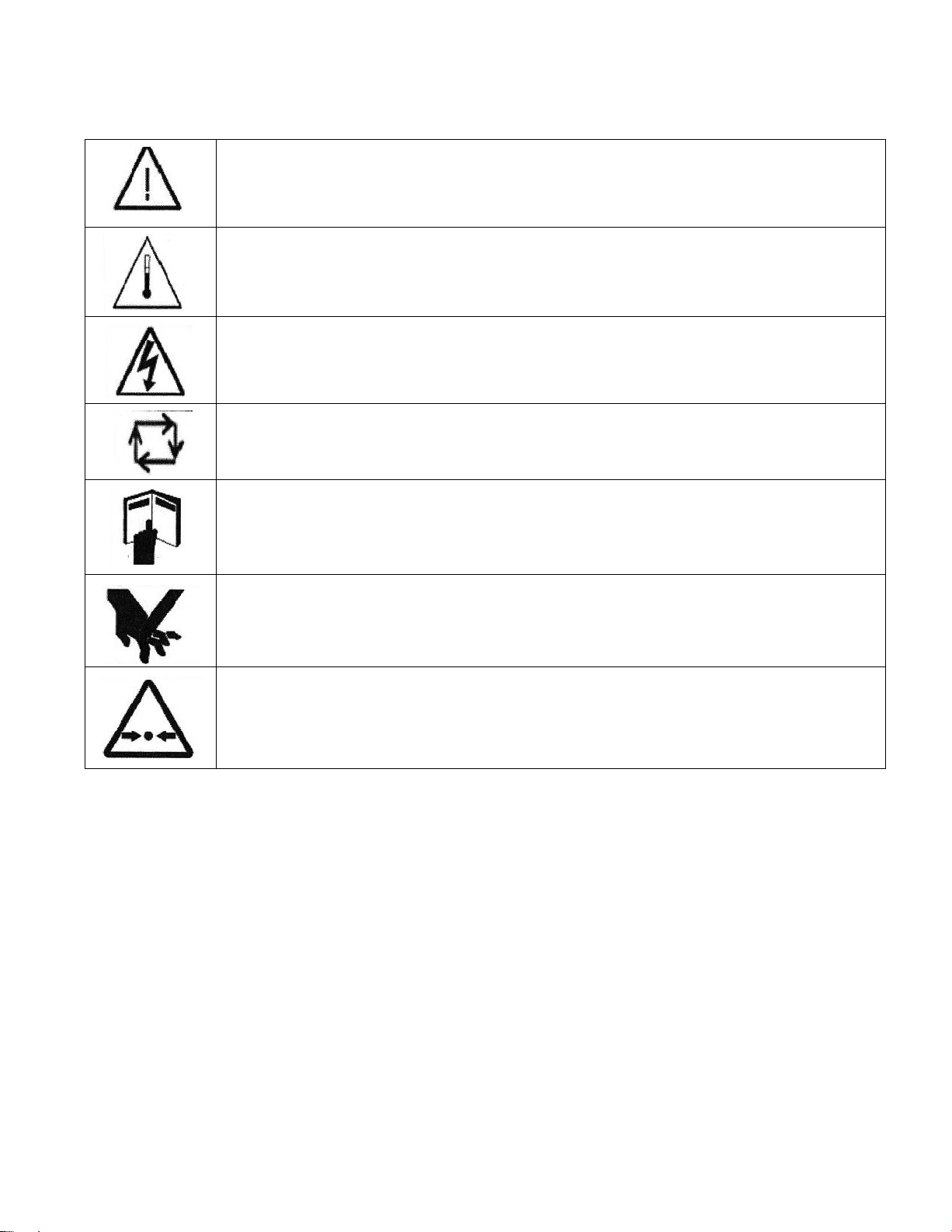
Generator Set Warning Labels
Warning signs are provided on the generator set at or near the point of risk. To avoid injury,
always take the necessary precautions – as indicated on the sample signs shown below:
Caution / Warning.
Indicates a risk of personal injury.
Caution / Warning of Temperature Hazard.
Indicates a risk of personal injury from high temperature.
Caution / Warning of High Voltage Hazard.
Indicates a risk of personal injury from electric shock/electrocution.
Caution / Warning.
Indicates a risk of personal injury from equipment that may be subject to
automatic starting or remote starting.
Caution / Warning.
Indicates to read Operator manual for additional information.
Caution / Warning of Belt and Rotating Part Hazard.
Indicates a risk of personal injury from entanglement in moving parts.
Caution / Warning of Pressure Hazard.
Indicates a risk of personal injury from pressurized fluids.
Copyright 2016 Cummins Inc.
7
Page 12

THIS PAGE IS INTENDED TO BE BLANK
8
Copyright 2016 Cummins Inc.
Page 13

Introduction
ABOUT THIS MANUAL
WARNING
severe personal injury, death and equipment
damage. The installer must be qualified to perform the installation of electrical and mechanical
equipment.
WARNING
tem. It can stop without warning. Children, persons with physical or mental limitations, and
pets could suffer personal injury or death. A personal attendant, redundant power or an alarm
system must be used if genset operation is critical.
WARNING
tected” and shall not be used in a flammable vapor environment.
CAUTION
placement of fuel, exhaust, air intake or speed
control system components that affect engine
emissions are prohibited by law in the State of
California.
This manual is a guide for the installation of the generator sets listed on the front cover. Proper installation is essential for top performance. Read through
this manual before starting the installation.
Improper installation can result in
This genset is not a life support sys-
This generator is not “ignition pro-
Unauthorized modifications or re-
This manual addresses the following aspects of the
installation:
Location and Mounting
Exhaust Connections
Fuel Connections
Electrical Connections
Startup
See the Operator’s Manual for operation and maintenance and the Service Manual for service.
Manuals are updated from time to time to reflect
changes in the equipment and its specifications. For
this reason, only the copy of the installation manual
supplied with the genset should be used as a guide for
the installation.
OUTLINE DRAWINGS
See the Outline Drawings (Pages 31 and 32) for
installation details: mounting bolt hole locations, connection points (fuel, battery, exhaust, remote control,
AC output), sizes and types of fittings, cooling air
openings, weight, and overall dimensions. See your
Cummins Onan dealer for a large-scale Outline
Drawing and full-size floor cutout template.
Copyright 2016 Cummins Inc.
9
Page 14

INSTALLATION CODES AND STANDARDS
FOR SAFETY
CAUTION
applies only when the genset is installed in a
Commercial or Recreational Vehicle.
The genset installer bears sole responsibility for the
selection of the appropriate genset, for its proper
installation and for obtaining approvals from the authorities (if any) having jurisdiction over the installation.
Federal, State and local codes, such as the California Administrative Code—Title 25 (RV installation),
might also be applicable. Installation codes and recommendations can change from time-to-time and
are different in different countries, states and municipalities. It is recommended that the standards in
Table 1 be obtained for reference.
TABLE 1. REFERENCE CODES AND STANDARDS
Code of Federal
Regulations:
Title 49: Chapter III,
Chapter V
National Electrical
NFPA No 70, 1192
ANSI/RVIA-EGS-1
California
Administrative Code:
Title 25, Chapter 3
CAN/CSA-Z240:
Recreational Vehicles
Bulletin 946
IEC 60364-7-708:
Electrical Installations
in Caravan Parks &
Caravans
The Commercial Genset Warranty
Superintendent of Documents
P. O. Box 371954
Pittsburgh, PA 15250-7954
Code:
National Fire Protection Association
470 Atlantic Avenue
Boston, MA 02210
Recreational Vehicle Industry Association
14650 Lee Road
Chantily, VA 22021
State of California Documents Section
P.O. Box 1015
North Highlands, CA 95660
Canadian Standards Association
Housing & Construction Materials
178 Rexdale Blvd.
Rexdale, Ontario, Canada M9W 1R3
International Electrotechnical Commission
3, Rue de Varembé
Geneva, Switzerland
NOISE
Generator sets emit noise. As noise level and time of
exposure increase, risk of hearing damage increases. The Specifications page n the Operator
manual states noise level for this generator set. Select and use personal hearing protection appropriate
for your exposure to generator set noise.
Note for use in countries where compliance to the EU
Noise directive is required: This generator set has
not been evaluated and is not marked for use in open
air. Install the generator set in accordance with the
Installation manual. Obey local noise restrictions
when you operate the generator set.
ELECTROMAGNETIC COMPATIBILITY
Generator sets emit and receive electromagnetic
(radio frequency) energy . If the generator set affects
operation of nearby devices, or nearby devices affect
generator set operation, increase the distance between them.
Note for use in countries where compliance to the
EMC directive is required: This generator set has
been evaluated for use in residential, commercial,
and light industrial environments.
10
Copyright 2016 Cummins Inc.
Page 15

Mounting, Location and Ventilation
MOUNTING
Installation of the generator set requires lifting apparatus. Ensure that correctly rated
lifting slings with suitable attachments are
available prior to commencing work. Lifting
and lowering operations should only be carried out by properly trained personnel. Do
not exceed the rating of any lifting component. Wear head, eye, hand and foot protection during lifting operations.
The generator set has a 2 point lifting system, which
is accessible through an access cover. Refer to outline drawing (p 24 and p 25) for the location of the access cover and weight of the generator set. Make
provisions accordingly for safe handling.
Support the genset on a structure able to resist the
dynamic weight of the genset:
3 g-force vertical and
1 g-force horizontal. See Specifications for the
weight of the genset. Use four Grade 5 screws
(3/8-16 UNC) to secure the genset to the floor or
frame. The screws must protrude at least 1/2 inch
(13 mm) but not more than 1 inch (25 mm) into the
base, as measured from the bottom surface of the
base. Torque the screws to 35 lb-ft (41 N-m).
WARNING
be designed and installed to support the dynamic weight of the genset. Failure to do so can result
in the genset dropping onto the roadway causing
property damage, severe personal injury and
death.
The genset support structure must
LOCATION
Typical genset locations on a vehicle are illustrated in
Figure 1.
Provide access to the operator’s console to start and
stop the genset and to check for and add engine
oil and coolant.
Provide access for connecting and disconnecting
fuel lines, battery cables, remote control wiring
and AC wiring.
Provide access for removing the front and bottom ac-
cess covers to perform periodic maintenance in
accordance with the Operator Manual. If the
genset compartment has a floor, use the floor
cutout template that is available from your Cummins Onan dealer. The crosshatched areas on
Page 16 indicate the areas that must be open in
the floor. These areas must not be obstructed by
frame members, exhaust tail pipes or other
equipment.
Make sure the genset clears the ground by at least
12 inches (305 mm) to provide adequate ventilation and reduce the amount of dust pulled in
by the cooling fan.
A genset compartment must be large enough to pro-
vide at least 1/2 inch (12.7 mm) clearance at the
top of the genset, 1/4 inch (6.4 mm) at the back
and left side, 2 inches (51 mm) at the front for air
intake and 4 inches (102 mm) at the right side for
air discharge (Figure 2). These minimum clear-
ances apply to any thermal or acoustic insulation with which the compartment may be lined.
Acoustic/thermal insulation and adhesive must be
Classified as “Self-Extinguishing” at not less
than 200
compartment with insulation, which absorbs
spilled fuel and oil.
Provide a vapor-tight, fire-resistive barrier between
the genset and the interior of the vehicle. Use
approved materials (26 gauge galvanized steel
or equivalent). See NFPA 1192 for details.
EXHAUST GAS IS DEADLY. Construct a suitable vapor barrier of approved materials between the genset and vehicle interior to keep
out exhaust gas.
Provide protection from rain and snow when the gen-
set is not mounted in a compartment. The genset housing is not water tight. Protection must
extend over the entire top of the genset, including the operator control panel.
F (90C). Do not line the bottom of the
Copyright 2016 Cummins Inc.
11
Page 16

Provide protection from direct road splash if the gen-
set is located behind a road wheel or the front
grille of the vehicle.
FIGURE 1. TYPICAL GENSET LOCATIONS
VENTILATION
Unrestricted air flow for cooling, ventilation and combustion (Figure 2) is essential for proper genset performance and service life. See HOT AIR RECIRCULATION TEST (Page 27).
The crosshatched areas on Page 16 must be open
for unobstructed air flow into and out of the genset for cooling, ventilation and combustion.
When the genset is installed in a compartment that
surrounds the top and sides (Figure 2), provide
non-flammable baffles (UL 94 HBF foam or better) to prevent hot side-discharge air from recirculating back into the front air inlet grille. The
baffles must extend all the way across the top,
down the front and half way back below the side
air discharge grille. They must close off the gap
between the genset and enclosure.
If the air inlet is in the compartment door, it must allow
the air to flow straight into each opening of the
inlet air grille without obstruction (Figure 2).
If the air inlet is in the compartment floor in front of the
genset, the opening must be at least 2 inches
(51 mm) wide and extend across the entire front
of the genset (crosshatched area, Page 16).
COMPARTMENT WITH BAFFLES
AND AIR OPENINGS ON SIDES OF GENSET
AIR OUTLET IN BOTTOM OF GENSET
FIGURE 2. GENSET COMPARTMENT WITH
BAFFLES TO PREVENT HOT AIR RECIRCULATION
The compartment outlet for side-discharge air must
be at least 4 inches (102 mm) wide and extend
across the back half of the floor (Figure 2).
12
Copyright 2016 Cummins Inc.
Page 17

Exhaust Connections
The exhaust system must be gas-tight and designed
to limit entry of exhaust gases into the vehicle.
WARNING
EXHAUST GAS IS DEADLY! To keep
exhaust gases from entering the vehicle do not
terminate the exhaust tailpipe underneath the
vehicle or closer than specified to openings into
the vehicle (Figure 6) or route it such that it is
likely to be damaged (Figure 7). Use approved
materials and parts only.
CAUTION
Unauthorized modifications or replacement of fuel, exhaust, air intake or speed
control system components that affect engine
emissions are prohibited by law in the State of
California.
MUFFLER
The muffler is mounted inside the genset housing
and has a flanged outlet opening (Figure 3). It has a
USDA (Forest Service) spark arrestor and meets
RVIA EGS-1 construction requirements. The Outline
Drawing (Page 16) shows the dimensions of the exhaust flange and the locations of the tailpipe clearance holes.
A genset without a properly installed and maintained
spark arresting exhaust system can cause a brush or
forest fire, and is illegal on federal lands. Liability for
damage, injury and warranty expense due to the
modification of the exhaust system or to use of unapproved parts is the responsibility of the person performing the modification or installing the unapproved
parts. Contact a Cummins Onan distributor for approved exhaust system parts.
SIDE AND BACK TAILPIPE
EXIT HOLES
MUFFLER OUTLET FLANGE
Copyright 2016 Cummins Inc.
FIGURE 3. EXHAUST CONNECTIONS AT GENSET
13
Page 18

TAILPIPE
The tailpipe of the generator set will be hot during operation and can cause severe burns. To reduce the risk of contact, consideration must be
taken on where the tailpipe will be located and
routed.
Tailpipe adapter kits are separately available. Use a
straight adapter for a tailpipe routed through the bottom. Use an elbow adapter for a tailpipe routed
through the side or back exit holes. When connecting
and routing the tailpipe:
Use 1-3/8 inch ID 18-gauge aluminized steel tubing
or equivalent (minimum 35 mm ID with minimum 0.012 mm wall thickness). Do not use flexible tubing, which is not gas tight or durable.
Secure the tailpipe or adapter flange to the muffler
flange with the gasket and two stainless steel
bolts supplied in the kit.
Use U-bolt muffler clamps to connect sections of tail-
pipe. It is recommended that the overlapping
pipe be slotted as shown in Figure 4.
3/4 INCH (19 MM)
MAXIMUM SLOT
(BOTH SIDES)
FIGURE 4. EXHAUST TAILPIPE CONNECTIONS
Use flexible automotive-type tailpipe hangers every
2 to 3 feet (0.6 to 0.9 m). Attach the hangers to
steel framework, not to wood or other combustible material.
Do not terminate the tailpipe underneath the vehicle.
Extend it a minimum of 1 inch (25 mm) beyond
the perimeter of the vehicle (Figure 5). Support
the end of the tailpipe such that it cannot be
pushed inward and up under the skirt of the vehicle.
Do not route the tailpipe such that it will interfere with
removing the service access cover and performing periodic maintenance. See the Operator
Manual.
Do not route the tailpipe closer than 3 inches
(76 mm) to combustible material (wood, felt,
cotton, organic fibers, etc.) unless it is insulated
or shielded. The temperature rise (above ambient) on adjacent combustible material must not
exceed 117
F (65C).
Do not route the tail pipe near fuel lines or fuel tanks.
1 INCH (25 mm)
MINIMUM
LAST TAILPIPE HANGER AS
CLOSE TO END AS
PRACTICAL
FIGURE 5. TERMINATING THE EXHAUST TAILPIPE
NO OPENING INTO THE VEHICLE INTERIOR MAY
BE CLOSER THAN 6 INCHES (153 mm) TO THE
END OF THE TAIL PIPE (WITHIN SHADED AREA)
6 in
153 mm
Do not terminate the tailpipe such that it is closer than
6 inches (153 mm) to any opening into the vehicle interior (door, window, vent). See Figure 6.
TAILPIPE
FIGURE 6. MINIMUM DISTANCES TO OPENINGS
Route the tailpipe such that it is not likely to be struck
when the vehicle is moving. Keep it out of the ap-
14
Copyright 2016 Cummins Inc.
Page 19

proach and departure angles of the vehicle and
above the axle clearance line (Figure 7).
Excessive back pressure can cause loss of
performance and engine damage.
Interconnecting the engine exhaust systems
will allow exhaust condensates and soot to
migrate into the engine that is idle, causing
engine damage.
Do not connect the genset to the vehicle engine ex-
haust system.
DEPARTURE
ANGLE
Exhaust back pressure under full load must not ex-
ceed 2 inches (51 mm) water column (WC) as
measured within 6 inches (154 mm) of the muffler outlet flange.
APPROACH
ANGLE
AXLE CLEARANCE LINE
FIGURE 7. APPROACH AND DEPARTURE ANGLES AND AXLE CLEARANCE LINE
Copyright 2016 Cummins Inc.
15
Page 20

THIS PAGE IS INTENDED TO BE BLANK
16
Copyright 2016 Cummins Inc.
Page 21

Fuel Connections
WARNING
Diesel fuel is a combustible and can
cause severe personal injury or death. Do not
smoke or allow any flame, spark, pilot light, arcproducing equipment, electrical switch or other
ignition source around fuel or fuel components,
or in areas sharing ventilation. Keep a type multi−class fire extinguisher handy.
Do not interconnect genset and vehicle engine fuel
lines. Follow the vehicle chassis manufacturer’s instructions when making connections to the vehicle
engine fuel tank.
CAUTION
Either or both engines could starve
for fuel if the genset and vehicle engine fuel lines
are interconnected. Always use separate fuel
lines or a separate fuel tank for the genset.
To prevent the genset from running the vehicle out of
fuel, do not extend the genset fuel pickup tube down
into the fuel tank as far as the pickup tube for the vehicle engine.
Fuel lines (supply and return) must have at least a
1/4 inch (6.4 mm) ID See Figure 8 for connections at
the genset.
Run the fuel line at or above the top of the fuel tank to
reduce the risk of siphoning fuel out of the tank if the
line should break. The maximum fuel pump lift is
36 inches (1 meter).
Route fuel lines away from electrical wiring and hot
engine exhaust components. Fuel lines should be
accessible for inspection and replacement, protected from damage and secured to prevent kinking,
contact with sharp edges and chafing due to vibration.
FUEL SUPPLY
(1/8 INCH NPT)
FUEL RETURN
(1/8 INCH NPT)
FIGURE 8. FUEL CONNECTIONS
Copyright 2016 Cummins Inc.
17
Page 22

BIO−DIESEL FUELS B5 − B20
Approved Bio−Diesel Fuel:
Bio−diesel meeting either ASTM D6751 or
EN14214.
Place the fuel water separator in a location that
is accessible for service by as close the generator set as possible. Locating the separator
ahead of the generator set fuel pump is acceptable.
Fuel meeting either ASTM D6751 or EN14214
fuel can be blended with an acceptable diesel
fuel meeting ASTM D975 meeting ASTMD975
up to 20 percent volume concentration (B20).
For bio−diesel blends above B5 and up to B20 the
following installation requirements must be met:
Supply and Return fuel lines and fittings must be
bio−diesel compatible. Not all fuel hoses and fittings are bio−diesel compatible. All fuel wetted
components must not contain the following materials: copper, brass, bronze, zinc, lead, tin,
natural rubber and nitrile rubber compounds.
Check with your manufacturer for bio−diesel
compatibility.
Fuel tanks must be made from the following ma-
terials: aluminum, steel, flourinated polyethylene, flourinated polypropylene or Teflon
(PTFE).
Verify the vehicle propulsion engine is capable
of using B20 when sharing the same fuel tank
with the generator set.
A bio−diesel compatible fuel water separator is
required. Cummins Onan strongly recommends
using Cummins Filtration filters equipped with
StrataPoret media. This filter media removes
water more efficiently than standard cellulosic
filter media, which will not provide adequate fuel
water separation capabilities. However, even
StrataPoret fuel filter media is not as effective
in removing water from bio−diesel as it is in re-
moving water from petro diesel. Therefore, preventing water from entering the fuel supply (vehicle or storage) remains very important.
Additional information:
Bio−diesel blends have higher pour and cloud
points than standard diesel fuels. Generator set
locations far from the fuel tank combined with
low fuel flow rates can make the generator set
fuel system very susceptible to fuel starvation
related to gelling in cold weather (below 23
C). In addition to electric or coolant tank
–5
F/
heaters, consideration to routing and possible
heating or insulation of the fuel lines to the generator set may be needed.
Bio−Diesel blends can oxidize more quickly
than standard diesel fuels; more frequent fuel filter service intervals may be required and shorter
fuel storage life in tanks is likely.
WARNING
It is highly recommended that specific
market applications are avoided or excercised with
extra care due to some of the properties of bio−diesel
fuel blends such as cold weather operation, long
term storage, material incompatibilities and other effects on engine operating characteristics. Such applications that should use standard fuels include applications that will experience seasonal usage,
storage for periods exceeding 60 days, and extreme
temperatures or humidity.
Storage requirements:
If using bio−diesel for seasonal applications
(stored more than 90 days), the generator set
must be purged before storage by running the
engine on pure diesel fuel meeting ASTM D975
for a minimum of 30 minutes.
18
Copyright 2016 Cummins Inc.
Page 23

TABLE 2. CUMMINS ONAN BIO−DIESEL RECOMMENDATIONS
APPLICATION
RECOMMENDATION FOR
BIO−DIESEL BLENDS
Emergency Standby
Not Recommended Use petroleum diesel only. Low fuel usage and critical
RV
Seasonal/Commercial with
low annual hour accumulation
Limited Time Prime Approved with
Recommendations
Unlimited Time Prime Approved with
Recommendations
Continuous Approved with
Recommendations
RECOMMENDATIONS COMMENTS
start nature of Emergency
Standby make bio−diesel
impractical.
Use fuel within 6 months of
manufacture. Flush fuel
system with petroleum diesel prior to storage.
Use fuel within 6 months of
manufacture. Fluh fuel system with petroleum diesel
Bio−diesel is suitable for
constant high load operation with proper precautions.
Bio−diesel is suitable for
variable load operation with
proper precautions.
prior to storage/transport.
Use fuel within 6 months of
manufacture.
Bio−diesel is suitable for
base load operation with
proper precautions.
Copyright 2016 Cummins Inc.
19
Page 24

THIS PAGE IS INTENDED TO BE BLANK
20
Copyright 2016 Cummins Inc.
Page 25

Electrical Connections
AC POWER CONNECTIONS
WARNING
uninsulated live parts inside the generator set
and connected equipment can result in severe
personal injury or death. For your protection,
stand on a dry wooden platform or rubber insulating mat, make sure your clothing, and shoes
are dry, remove jewelry from your hands and use
tools with insulated handles. Secure protective
covers when completing installation.
WARNING
electric shock resulting in severe personal injury
or death.
WARNING
cause severe personal injury or death. Do not
connect the starting battery until so instructed in
Installation Review and Startup.
HAZARDOUS VOLTAGE! Touching
IMPROPER WIRING can cause fire or
Accidental starting of the genset can
Wiring Methods
The genset is equipped with a terminal block and
conduit connector knockouts for AC power output
connections (Figure 9). See the generator connection diagrams on Page 34.
terminals must be re-torqued after a few minutes because the connection can loosen if the
individual strands spread out.
Use vibration-proof switches and controls to prevent
the opening and closing of circuits while the vehicle is in motion.
Use rain-tight conduit, conduit connectors and junc-
tion boxes for all exterior wiring.
Provide ground fault circuit interrupters (GFCIs) or
residual current devices (RCDs) for all convenience power receptacles.
Seal all conduit openings into the vehicle interior to
keep out exhaust gas. Apply silicone rubber or
equivalent sealant inside and outside each conduit connector. (Flexible conduit is not vaportight and will allow exhaust gas to enter along
the wires if not sealed.)
Route or protect AC wiring so that it will not be cut or
abraded, exposed to hot surfaces or damaged
by road debris. Keep AC wiring away from fuel
lines and control wiring (see Remote Control).
AC TERMINAL
ACCESS
AC wiring methods must be in accordance with the
National Electrical Code or IEC 60364-7-708, as appropriate. Note especially the following:
WARNING
EXHAUST GAS IS DEADLY! Seal all
wiring openings into the vehicle interior to keep
out exhaust gas.
WARNING
Routing AC wiring with fuel lines can
lead to fire and severe personal injury or death.
Keep AC wiring away from fuel lines.
Have a trained and experienced electrician super-
vise and inspect the installation of all AC wiring.
Secure only one lead at each AC output terminal.
The terminals are suitable for wire gauges up to
No. 6 AWG (16 mm
2
). Torque the terminals to
13 in-lbs (1.5 N-m). When stranded conductors
are used, it is recommended that copper ferrules, available for the various wire gauges, be
crimped on the stripped ends of the conductors
to facilitate terminal connections. Otherwise, the
CONTROL
KNOCKOUTS FOR 3/4
AND 1 INCH CONDUIT
FIGURE 9. ACCESS FOR AC OUTPUT AND
REMOTE CONTROL CONNECTIONS
WIRING
KNOCKOUTS
Copyright 2016 Cummins Inc.
21
Page 26

Grounding
WARNING
electrocution and severe personal injury or
death. Grounding must be in accordance with
applicable codes.
Faulty grounding can lead to fire or
screw on the red, hexagonal insulator. Cut the jumper as close to each terminal connector as possible to
avoid having to loosen the connections for the other
wires at the terminals.
Vehicle Connections to Utility Power
Connect grounding terminal TB1-5 (Page 34) in accordance with applicable codes.
50 Hz Model HDKBB Only − If the authority having
jurisdiction requires an ungrounded 230 VAC system, it will be necessary to cut the internal grounding
jumper (Figure 10). To do this, remove the side access cover (four screws) and cut the short jumper between the ground terminal screw and the terminal
WARNING
Interconnecting the genset and the
public utility (or any other power source) can
lead to electrocution of utility line workers,
equipment damage and fire. Use an approved
switching device to prevent interconnections.
A vehicle with provisions for connecting utility power
must have an approved device to keep the genset
and utility from being interconnected.
FOR UNGROUNDED 230 VAC, 50 HZ APPLICATIONS, CUT
THIS JUMPER FROM ITS TERMINAL CONNECTORS
DO NOT LOOSEN THE TERMINAL SCREWS
FIGURE 10. MODEL HDKBB GROUNDING JUMPER
22
Copyright 2016 Cummins Inc.
Page 27

REMOTE CONTROL CONNECTIONS
Leads for connection to a remote control panel are
terminated in a 10-pin sealed connector and are
stowed inside the AC terminal enclosure when the
genset leaves the factory. Details of the connector
and its mate are provided on the Outline Drawing
(Figure 15). Refer to the Wiring Schematic (Figure 17) for pin connections.
Remote Control Panels
Onan offers harnesses of various lengths with mating receptacles and three remote control kits as follows:
Remote switch / status lamp.
Remote switch / status lamp and hour meter.
Remote switch / status lamp and DC voltmeter.
If another source is used for the remote panel:
The control switch should be a two-pole, momentary-
contact, center-return/center-off type of switch
with an indicator light.
nect to the wiring from the remote panel. Use insulated 18 AWG ( 1 mm
2
) copper conductors for
the wiring from the remote panel.
Keep control leads away from AC power leads to re-
duce the possibility of erratic operation due to induced signals.
Seal the hole where the leads enter the interior of the
vehicle to keep out exhaust gas. Use silicone
rubber or an equivalent type of sealant.
BATTERY CONNECTIONS
WARNING
cause severe personal injury or death. Do not
connect the starting battery until so instructed in
Installation Review and Startup. Make sure an
automatic genset starting system is disabled.
Accidental starting of the genset can
Battery Capacity
The genset has a 12 VDC, negative-ground control
and starting system. See Specifications for the re-
quirements for cranking batteries.
The total load connected to P2-E (Switched B+)
should not exceed 2 amp.
The total load connected to P2-F (Status Light)
should not exceed 2 amp.
Wiring Methods
WARNING
wiring openings into the vehicle interior to keep
out exhaust gas.
Remove the AC terminal access cover and remove
one of the control wiring knockouts.
Pull out the remote control connector plug, fit the
bushing around the connector leads into the
knockout slot and secure the access cover.
Snap the connector plug and harness receptacle to-
gether.
If the harness does not have a plug for connections
at the control panel, use solder-type butt connectors and heat-shrink insulation tubing to con-
EXHAUST GAS IS DEADLY! Seal all
Battery Recharging
The genset is equipped with a 10-amp, regulatedvoltage battery charger.
Battery Compartment
Batteries must be mounted in a separate compartment from that of the genset and away from sparkproducing equipment. An enclosed compartment
must have openings of at least 1.7 square inches
(11 square centimeters) at the top and bottom for
ventilation of battery gasses. Batteries should be
mounted such that spills and leaks will not drip acid
on fuel lines, wiring and other equipment that could
be damaged.
WARNING
drogen gas given off by the battery, causing severe personal injury. The battery compartment
must be ventilated and must isolate the battery
from spark-producing equipment.
Arcing can ignite the explosive hy-
Copyright 2016 Cummins Inc.
23
Page 28

Battery Cables
Battery wiring methods must be in accordance with
the National Electrical Code or IEC 60364-7-708, as
appropriate.
Size battery cables according to Table 3. The current
path between the genset and the negative (−) battery
terminal must also be able to carry full cranking current without causing excessive voltage drop. It is
highly recommended that a full-length cable be used
to connect the genset to the negative (−) battery ter-
minal (Figure 1 1). Note also that codes may require a
bonding conductor between the genset and vehicle
frame and between the battery and vehicle frame.
If the vehicle frame is used as the path between the
negative (−) battery terminal and the genset (Figure 12), all frame members in the path of battery
cranking currents must have substantial cross sections. The electrical resistance of riveted or bolted
frame joints must also be carefully considered, especially if the joints will be exposed to corrosive conditions. A cable sized according to Table 3 must be
used to connect the frame to the designated negative
(−) terminal on the genset (Figure 12). The genset
mounting bolts are not considered adequate
means for bonding the genset to the vehicle
frame, either for the purpose of carrying cranking currents or for complying with requirements
for genset/system grounding.
WARNING
lines can lead to fire and severe personal injury
or death. Keep battery cables away from fuel
lines.
Routing battery cables with fuel
TABLE 3. BATTERY CABLE SIZES FOR AMBIENT
TEMPERATURES DOWN TO −20 F (−29 C)
TOTAL CABLE LENGTH,
FEET (METERS)
0 to 15 (0 to 4.5) 0* (50)
16 to 20 (4.5 to 6) 000 (95)
* − A total length of up to 25 feet (7.6 meters) may be
used in warmer climates or when battery capacity totals
at least 1200 CCA (Cold Cranking Amps).
SIZE PER TABLE 3
GENSET
+
−
VEHICLE FRAME
FIGURE 11. FULL-LENGTH CABLE FROM
BATTERY NEGATIVE (−) TERMINAL
GENSET
+
−
VEHICLE FRAME
FIGURE 12. VEHICLE FRAME AS PATH FROM
BATTERY NEGATIVE (−) TERMINAL
8 AWG
2
(10mm
MINIMUM
SIZE PER TABLE 3
)
CABLE SIZE,
AWG (mm
− +
BAT
− +
BAT
2
)
Route battery cables away from fuel lines and hot engine exhaust components. Battery cables should be
accessible for inspection and replacement, protected from damage and secured to prevent chafing
due to vibration.
24
Copyright 2016 Cummins Inc.
Page 29

Genset Bonding Terminal
The negative (−) battery cable terminal shown in Fig-
ure 13 is also the bonding terminal for grounding the
genset to the vehicle chassis. If the grounding cable
is also going to carry starter motor current, it must be
sized the same as the battery cables.
Connecting Battery and Bonding Cables
Terminate the battery cables with ring terminals
sized for the 5/16 inch genset terminal screws (Figure 13). Permanently mark each end of each cable
as to its polarity, positive (+) or negative (−). After
making sure the battery cables are not connected at
the battery and that an automatic genset starting system is disabled, connect the battery and grounding
cables to the genset. Torque the terminals to 7.5 lb-ft
(10 N−m).
POSITIVE (+)
NEGATIVE (−)
FIGURE 13. BATTERY CABLE TERMINALS
Copyright 2016 Cummins Inc.
25
Page 30

THIS PAGE IS INTENDED TO BE BLANK
26
Copyright 2016 Cummins Inc.
Page 31

Installation Review and Startup
LOCATION
HOT AIR RECIRCULATION TEST
A representative installation of the genset must be
tested to determine that the genset will not overheat
due to recirculation of hot air back into the genset.
Test Method
Complete a representative installation.
Conduct the test in a well ventilated space in which
carbon monoxide cannot accumulate, but that is
protected from cross drafts that could affect temperature measurements.
Connect a large, constant load to the genset. If a load
bank is available, connect at least 3/4 full load.
If not, connect and run the largest combination
of constant loads that can be kept on during the
test without tripping the genset circuit breaker.
For example, run a combination of air conditioners and lights. Make sure air conditioners stay
on and do not cycle during the test.
Measure temperatures with thermocouples not
heavier than No. 24 AWG (0.21 mm
Measure genset inlet air temperature with one ther-
mocouple tied in the middle of the inlet air grille
(Figure 14).
Measure ambient air temperature with a shielded
thermocouple within 4 feet (1.2 meters) of the
genset and at approximately the same height.
Make sure the thermocouple will not b e a ffected
2
).
by warm air discharged from the genset or by
sunlight. Use 2 inch diameter white PVC piping
at least 6 inches long as a thermocouple shield.
Close all genset compartment doors and run the
genset for at least 90 minutes. Record temperatures at 15 minute intervals. See Table 4 for an
example of how the data can be arranged for recording and analysis.
TABLE 4. TEMPERATURE DATA
TEMPERATURE C (F)
THERMOCOUPLE
AMBIENT AIR
INLET AIR
Time Of Reading
Test Requirement
The rise in inlet air temperature over ambient air temperature must not exceed 15F (8C). A rise in inlet
air temperature indicates hot air recirculation. If the
rise exceeds the requirement, steps must be taken to
reduce recirculation to an acceptable level. Review
Mounting, Location and Venting (Page 11).
CAUTION
tures can reduce maximum genset power if the
air temperature rise in this test is on the high end
of the acceptable range.
High ambient operating tempera-
Copyright 2016 Cummins Inc.
AMBIENT AIR
INLET AIR
FIGURE 14. THERMOCOUPLE LOCATIONS
27
Page 32

INSTALLATION REVIEW
Before starting the genset inspect the installation
and check off (
can be answered “YES”. If a question cannot be
checked off, review the appropriate section in the
manual.
[ ] Is the operator’s console easily accessible for
starting and stopping the genset, resetting circuit breakers and checking and adding engine
coolant?
[ ] Is the genset securely bolted in place?
[ ] Is there clearance all around the genset?
[ ] Are the cooling and combustion air inlet and out-
let openings free of obstructions?
[ ] Is there easy access for draining the engine oil?
[ ] Is there easy access for draining the engine
coolant?
[ ] Is there easy access for changing the air filter,
checking oil level and adding oil?
[ ] Is there easy access for cleaning out the spark-
arrest muffler?
[ ] Are all tailpipe connections tight and all hangers
and support straps secure?
[ ] Does the tailpipe terminate at least 1 inch
(25 mm) beyond the perimeter of the vehicle
and at least 6 inches (153 mm) away from any
opening into the vehicle?
[ ] Is the tailpipe routed such that it is not likely to be
struck while the vehicle is moving?
[ ] Is the genset located outside the interior space
of the vehicle and separated by approved vapor-
tight and fire-resistive materials?
[ ] Are all wiring holes into the vehicle interior (in-
side and outside conduit connectors) sealed to
keep out exhaust gas?
[ ] Have the AC output connections been made
properly.
[ ] Have properly sized batteries and battery
cables been installed?
[ ] Have the battery cables been secured at suffi-
cient intervals to prevent chaffing and contact
with sharp edges, fuel lines and hot exhaust
parts?
[ ] Is the genset bonding terminal (negative [−] bat-
tery cable terminal) properly grounded to the ve-
hicle chassis?
[ ] Are all fuel connections tight?
[ ] Have the fuel lines been secured at sufficient in-
tervals to prevent chaffing and contact with
) each of the following questions if it
sharp edges, electrical wiring and hot exhaust
parts?
[ ] Is the genset protected from direct road splash,
rain and snow?
[ ] Does the genset clear the ground by at least
12 inches (305 mm)?
[ ] Has the HOT AIR RECIRCULATION TEST
been conducted? Are the results acceptable?
STARTUP
When all installation requirements have been met,
connect the battery cables to the battery, positive (+)
cable first.
WARNING
switches or other equipment, and flames or
sparks, can ignite battery gas causing severe
personal injury. To prevent injury:
fore working on or near
OFF away from battery
nect charger before
cables
Disconnect negative (−) cable first and
Read through the Operator Manual and perform the
maintenance and pre-start checks instructed. The
genset is shipped from the factory with proper levels
of engine oil and coolant, which should nevertheless
be checked before the genset is started. Start and
operate the genset, following all the instructions and
precautions in the Operator Manual.
WARNING
operate the genset when the vehicle is indoors
unless there is ample fresh air ventilation.
Check for fuel, coolant and exhaust leaks and unusual noises while the genset is running under full and
intermediate loads. To calculate electrical loads see
POWERING EQUIPMENT in the Operator Manual.
Do not place the genset in service until all leaks have
been fixed and operation is satisfactory.
Arcing at battery terminals or in light
Ventilate battery area be-
battery
Wear safety glasses
Do not smoke
Switch work light ON or
Stop genset and discon-
disconnecting battery
reconnect it last.
EXHAUST GAS IS DEADLY! Do not
28
Copyright 2016 Cummins Inc.
Page 33

Specifications
HDKBB HDKBC
GENSET CONTROLLER: Integrated Microprocessor Based Engine and Generator Controller
GENERATOR: Two-Bearing, Two-Pole Rotating Field, “Poly-Vee” Belt Drive
Power (@1.0 PF) 4800 W 5000 W
RPM 3000 3600
Frequency 50 Hz 60 Hz
Voltage 230V 1-Ph 120V 1-Ph, 120/240V 1-Ph, or 120/240V 3-Ph
Current 21 A 41.7/20.8 A or 12 A (3-Ph)
Circuit Breakers 2-pole 25 A (1 pole used) 2-pole 25 A (1-Ph) or 3-pole 15 A (3-Ph)
FUEL CONSUMPTION:
No-load
Half-load
Full-load
ENGINE: 2-Cylinder In-Line, Water-Cooled, Indirect-Injection, 4-Stroke Cycle Diesel
RPM 2880 2880
Bore 2.64 in (67 mm) 2.64 in (67 mm)
Stroke 2.68 in (68 mm) 2.68 in (68 mm)
Displacement 29.23 in3 (479 cc) 29.23 in3 (479 cc)
Compression Ratio 23 : 1 23 : 1
Injection Order 1−2 1−2
Engine Timing 18.25 to 19.75 BTDC 18.25 to 19.75 BTDC
Fuel Nozzle Injection
Pressure
Valve Lash: Intake & Ex-
haust (cold)
Oil Capacity
(with filter)
Cooling System
Capacity
0.0057 − 0.0073 inch (0.145 − 0.185 mm) 0.0057 − 0.0073 inch (0.145 − 0.185 mm)
DC SYSTEM:
Nominal Battery
Voltage
Minimum Battery
Capacity CCA
(Cold Cranking Amps)
Fuse F1 (control, start
and glow plug circuits)
650 amps down to −20F (−29C)
WEIGHT: 400 lbs (181 kg)
SIZE (L x W x H): 34.5 x 22.9 x 20.3 in (876 x 581.2 x 514.4 mm)
SOUND LEVEL: 68 dB(A) @ 10 ft (3m) before installation and @ 1/2-load
0.20 gph (0.74 lph)
0.32 gph (1.23 lph)
0.54 gph (2.04 lph)
1991 psi (13.73 mPa) 1991 psi (13.73 mPa)
2 quart (1.9 liter) 2 quart (1.9 liter)
3.0 quart (2.8 liter) 3.0 quart (2.8 liter)
12 volts 12 volts
475 amps down to 0F (−17C)
650 amps down to −20F (−29C)
30 amp mini-bayonet 30 amp mini-bayonet
0.25 gph (0.95 lph)
0.39 gph (1.47 lph)
0.60 gph (2.27 lph)
475 amps down to 0F (−17C)
Copyright 2016 Cummins Inc.
29
Page 34

THIS PAGE IS INTENDED TO BE BLANK
30
Copyright 2016 Cummins Inc.
Page 35

FIGURE 15. OUTLINE DRAWING—SHEET 1
Copyright 2016 Cummins Inc.
31
Page 36

FIGURE 16. OUTLINE DRAWING—SHEET 2
32
Copyright 2016 Cummins Inc.
Page 37

FIGURE 17. WIRING DIAGRAM—SHEET 1
Copyright 2016 Cummins Inc.
33
Page 38

FIGURE 18. WIRING DIAGRAM—SHEET 2
34
Copyright 2016 Cummins Inc.
Page 39

Page 40

power.cummins.com
Copyright E 2016 Cummins Inc. All rights reserved.
Cummins, Onan, the “C” logo, and “Performance you rely on.” are trademarks of Cummins Inc.
Other company, product, or service names may be trademarks or service marks of others.
Specifications are subject to change without notice.
 Loading...