

Page 1
Models
GGHB
GGHC
GGHD
Detector™/Sentinel™ Controls
GENERATOR SETS
Printed in U.S.A. 928-0133B 11-98
Page 2
Safety Precautions
Before operating the generator set (genset), read the
Operator’s Manual and become familiar with it and the
equipment. Safe and efficient operation can be
achieved only if the equipment is properly operated
and maintained. Many accidents are caused by failure
to follow fundamental rules and precautions.
The following symbols, found throughout this manual,
alert you to potentially dangerous conditions to the operator, service personnel, or the equipment.
This symbol warns of immediate
hazards which will result in severe personal injury or death.
WARNING
This symbol refers to a hazard or unsafe practice which can result in severe personal injury or death.
CAUTION
This symbol refers to a hazard or unsafe practice which can result in personal injury
or product or property damage.
FUEL AND FUMES ARE FLAMMABLE
Fire, explosion, and personal injury or death can result
from improper practices.
• Be sure all fuel supplies have a positive shutoff
valve.
• Be sure battery area has been well-ventilated prior
to servicing near it. Lead-acid batteries emit a highly
explosive hydrogen gas that can be ignited by arcing, sparking, smoking, etc.
EXHAUST GASES ARE DEADLY
Provide an adequate exhaust system to properly
•
expel discharged gases away from enclosed or
sheltered areas and areas where individuals are
likely to congregate. Visually and audibly inspect
the exhaust daily for leaks per the maintenance
schedule. Make sure that exhaust manifolds are secured and not warped. Do not use exhaust gases to
heat a compartment.
• Be sure the unit is well ventilated.
• Engine exhaust and some of its constituents are
known to the state of California to cause cancer,
birth defects, and other reproductive harm.
MOVING PARTS CAN CAUSE SEVERE
PERSONAL INJURY OR DEATH
• DO NOT fill fuel tanks while engine is running, un-
less tanks are outside the engine compartment.
Fuel contact with hot engine or exhaust is a potential
fire hazard.
• DO NOT permit any flame, cigarette, pilot light,
spark, arcing equipment, or other ignition source
near the generator set or fuel tank.
• Fuel lines must be adequately secured and free of
leaks. Fuel connection at the engine should be
made with an approved flexible line. Do not use
copper piping on flexible lines as copper will become brittle if continuously vibrated or repeatedly
bent.
• Natural gas is lighter than air, and will tend to gather
under hoods. Propane is heavier than air, and will
tend to gather in sumps or low areas. NFPA code requires all persons handling propane to be trained
and qualified.
• Keep your hands, clothing, and jewelry away from
moving parts.
• Before starting work on the generator set, discon-
nect battery charger from its AC source, then disconnect starting batteries, negative (-) cable first.
This will prevent accidental starting.
• Make sure that fasteners on the generator set are
secure. Tighten supports and clamps, keep guards
in position over fans, drive belts, etc.
• Do not wear loose clothing or jewelry in the vicinity of
moving parts, or while working on electrical equipment. Loose clothing and jewelry can become
caught in moving parts. Jewelry can short out electrical contacts and cause shock or burning.
• If adjustment must be made while the unit is run-
ning, use extreme caution around hot manifolds,
moving parts, etc.
MS-1
iii
Page 3
ELECTRICAL SHOCK CAN CAUSE
SEVERE PERSONAL INJURY OR DEATH
•
Remove electric power before removing protective
shields or touching electrical equipment. Use rubber insulative mats placed on dry wood platforms
over floors that are metal or concrete when around
electrical equipment. Do not wear damp clothing
(particularly wet shoes) or allow skin surface to be
damp when handling electrical equipment.
• Use extreme caution when working on electrical
components. High voltages can cause injury or
death. DO NOT tamper with interlocks.
• Follow all applicable state and local electrical
codes. Have all electrical installations performed by
a qualified licensed electrician. Tag and lock open
switches to avoid accidental closure.
• DO NOT CONNECT GENERATOR SET DI-
RECTLY TO ANY BUILDING ELECTRICAL SYS-
TEM. Hazardous voltages can flow from the gen-
erator set into the utility line. This creates a potential
for electrocution or property damage. Connect only
through an approved isolation switch or an ap-
proved paralleling device.
GENERAL SAFETY PRECAUTIONS
Coolants under pressure have a higher boiling point
•
than water. DO NOT open a radiator or heat ex-
changer pressure cap while the engine is running.
Allow the generator set to cool and bleed the system
pressure first.
• Benzene and lead, found in some gasoline, have
been identified by some state and federal agencies
as causing cancer or reproductive toxicity. When
checking, draining or adding gasoline, take care not
to ingest, breathe the fumes, or contact gasoline.
• Used engine oils have been identified by some state
or federal agencies as causing cancer or reproductive toxicity. When checking or changing engine oil,
take care not to ingest, breathe the fumes, or con-
tact used oil.
• Provide appropriate fire extinguishers and install
them in convenient locations. Consult the local fire
department for the correct type of extinguisher to
use. Do not use foam on electrical fires. Use extin-
guishers rated ABC by NFPA.
• Make sure that rags are not left on or near the en-
gine.
• Remove all unnecessary grease and oil from the
unit. Accumulated grease and oil can cause over-
heating and engine damage which present a poten-
tial fire hazard.
• Keep the generator set and the surrounding area
clean and free from obstructions. Remove any de-
bris from the set and keep the floor clean and dry.
• Do not work on this equipment when mentally or
physically fatigued, or after consuming any alcohol
or drug that makes the operation of equipment un-
safe.
• Substances in exhaust gases have been identified
by some state or federal agencies as causing can-
cer or reproductive toxicity. Take care not to breath
or ingest or come into contact with exhaust gases.
KEEP THIS MANUAL NEAR THE GENSET FOR EASY REFERENCE
iv
Page 4
Table of Contents
SECTION TITLE PAGE
SAFETY PRECAUTIONS iii. . . . . . . . . . . . . . . . . . . . . . . . . . . . . . . . . . . . .
1 INTRODUCTION
General 1-1. . . . . . . . . . . . . . . . . . . . . . . . . . . . . . . . . . . . . . . . . . . . . . . . . . . . . . . .
How to Obtain Service 1-2. . . . . . . . . . . . . . . . . . . . . . . . . . . . . . . . . . . . . . . . . . .
2 SPECIFICATIONS 2-1. . . . . . . . . . . . . . . . . . . . . . . . . . . . . . . . . . . . . . . . . . .
3 OPERATION (DETECTOR CONTROL)
General 3-1. . . . . . . . . . . . . . . . . . . . . . . . . . . . . . . . . . . . . . . . . . . . . . . . . . . . . . . .
Prestart Checks 3-1. . . . . . . . . . . . . . . . . . . . . . . . . . . . . . . . . . . . . . . . . . . . . . . . .
Control Panel 3-1. . . . . . . . . . . . . . . . . . . . . . . . . . . . . . . . . . . . . . . . . . . . . . . . . . .
Generator AC Voltage Regulator 3-5. . . . . . . . . . . . . . . . . . . . . . . . . . . . . . . . . .
Engine Control Module 3-5. . . . . . . . . . . . . . . . . . . . . . . . . . . . . . . . . . . . . . . . . . .
Starting 3-6. . . . . . . . . . . . . . . . . . . . . . . . . . . . . . . . . . . . . . . . . . . . . . . . . . . . . . . .
Stopping 3-6. . . . . . . . . . . . . . . . . . . . . . . . . . . . . . . . . . . . . . . . . . . . . . . . . . . . . . .
4 TROUBLESHOOTING (DETECTOR CONTROL)
Safety Considerations 4-1. . . . . . . . . . . . . . . . . . . . . . . . . . . . . . . . . . . . . . . . . . . .
Troubleshooting Charts 4-2. . . . . . . . . . . . . . . . . . . . . . . . . . . . . . . . . . . . . . . . . . .
5 OPERATION (SENTINEL CONTROL)
General 5-1. . . . . . . . . . . . . . . . . . . . . . . . . . . . . . . . . . . . . . . . . . . . . . . . . . . . . . . .
Prestart Checks 5-1. . . . . . . . . . . . . . . . . . . . . . . . . . . . . . . . . . . . . . . . . . . . . . . . .
Control Panel 5-1. . . . . . . . . . . . . . . . . . . . . . . . . . . . . . . . . . . . . . . . . . . . . . . . . . .
Generator AC Voltage Regulator 5-3. . . . . . . . . . . . . . . . . . . . . . . . . . . . . . . . . .
Engine Monitoring 5-3. . . . . . . . . . . . . . . . . . . . . . . . . . . . . . . . . . . . . . . . . . . . . . .
Starting 5-3. . . . . . . . . . . . . . . . . . . . . . . . . . . . . . . . . . . . . . . . . . . . . . . . . . . . . . . .
Stopping 5-4. . . . . . . . . . . . . . . . . . . . . . . . . . . . . . . . . . . . . . . . . . . . . . . . . . . . . . .
6 TROUBLESHOOTING (SENTINEL CONTROL)
Safety Considerations 6-1. . . . . . . . . . . . . . . . . . . . . . . . . . . . . . . . . . . . . . . . . . . .
Troubleshooting Charts 6-2. . . . . . . . . . . . . . . . . . . . . . . . . . . . . . . . . . . . . . . . . . .
!!
The engine exhaust from this product
contains chemicals known to the State
of California to cause cancer, birth
defects or other reproductive harm.
i
Page 5
SECTION TITLE PAGE
7 MAINTENANCE
General 7-1. . . . . . . . . . . . . . . . . . . . . . . . . . . . . . . . . . . . . . . . . . . . . . . . . . . . . . . .
Maintenance Schedule 7-2. . . . . . . . . . . . . . . . . . . . . . . . . . . . . . . . . . . . . . . . . . .
Generator Set Inspection 7-3. . . . . . . . . . . . . . . . . . . . . . . . . . . . . . . . . . . . . . . . .
Lubrication System 7-5. . . . . . . . . . . . . . . . . . . . . . . . . . . . . . . . . . . . . . . . . . . . . .
Cooling System 7-7. . . . . . . . . . . . . . . . . . . . . . . . . . . . . . . . . . . . . . . . . . . . . . . . .
Air Filter 7-9. . . . . . . . . . . . . . . . . . . . . . . . . . . . . . . . . . . . . . . . . . . . . . . . . . . . . . . .
Drive Belt 7-10. . . . . . . . . . . . . . . . . . . . . . . . . . . . . . . . . . . . . . . . . . . . . . . . . . . . . .
Ignition System 7-11. . . . . . . . . . . . . . . . . . . . . . . . . . . . . . . . . . . . . . . . . . . . . . . . .
Battery 7-12. . . . . . . . . . . . . . . . . . . . . . . . . . . . . . . . . . . . . . . . . . . . . . . . . . . . . . . .
Out-of-Service Protection 7-12. . . . . . . . . . . . . . . . . . . . . . . . . . . . . . . . . . . . . . . .
8 ADJUSTMENTS
Output Voltage Adjustment 8-1. . . . . . . . . . . . . . . . . . . . . . . . . . . . . . . . . . . . . . .
Fuel System Adjustments 8-1. . . . . . . . . . . . . . . . . . . . . . . . . . . . . . . . . . . . . . . . .
9 OPERATING RECOMMENDATIONS
Break-In 9-1. . . . . . . . . . . . . . . . . . . . . . . . . . . . . . . . . . . . . . . . . . . . . . . . . . . . . . . .
No-Load Operation 9-1. . . . . . . . . . . . . . . . . . . . . . . . . . . . . . . . . . . . . . . . . . . . . .
Exercise Period 9-1. . . . . . . . . . . . . . . . . . . . . . . . . . . . . . . . . . . . . . . . . . . . . . . . .
Low Operating Temperatures 9-1. . . . . . . . . . . . . . . . . . . . . . . . . . . . . . . . . . . . .
Power Rating Factors 9-1. . . . . . . . . . . . . . . . . . . . . . . . . . . . . . . . . . . . . . . . . . . .
ii
Page 6
1. Introduction
GENERAL
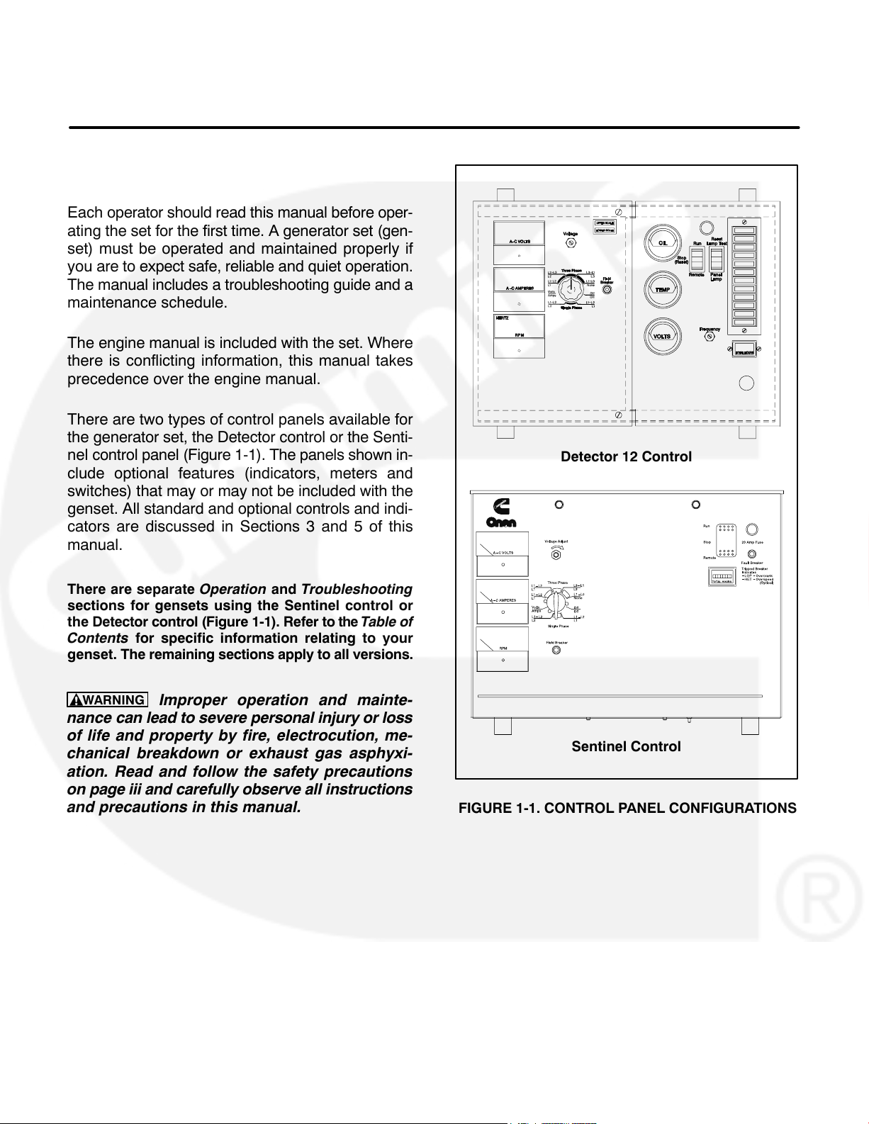
Each operator should read this manual before oper-
ating the set for the first time. A generator set (gen-
set) must be operated and maintained properly if
you are to expect safe, reliable and quiet operation.
The manual includes a troubleshooting guide and a
maintenance schedule.
The engine manual is included with the set. Where
there is conflicting information, this manual takes
precedence over the engine manual.
There are two types of control panels available for
the generator set, the Detector control or the Senti-
nel control panel (Figure 1-1). The panels shown in-
clude optional features (indicators, meters and
switches) that may or may not be included with the
genset. All standard and optional controls and indi-
cators are discussed in Sections 3 and 5 of this
manual.
Detector 12 Control
There are separate Operation and Troubleshooting
sections for gensets using the Sentinel control or
the Detector control (Figure 1-1). Refer to the Table of
Contents for specific information relating to your
genset. The remaining sections apply to all versions.
WARNING
nance can lead to severe personal injury or loss
of life and property by fire, electrocution, me-
chanical breakdown or exhaust gas asphyxi-
ation. Read and follow the safety precautions
on page iii and carefully observe all instructions
and precautions in this manual.
Improper operation and mainte-
Sentinel Control
FIGURE 1-1. CONTROL PANEL CONFIGURATIONS
1-1
Page 7
HOW TO OBTAIN SERVICE
When the generator set requires servicing, contact
your nearest Cummins
tor. Factory-trained Parts and Service representatives are ready to handle all your service needs.
®
/Onan® dealer or distribu-
1-800-888-ONAN (this automated service utilizes
touch-tone phones only). By entering your area
code and the first three digits of your local telephone
number, you will receive the name and telephone
number of the distributor nearest you.
If you are unable to locate a dealer or distributor,
consult the Yellow Pages. Typically, our distributors
are listed under:
For outside North America, call Onan Corporation,
1-612-574-5000, 7:30 AM to 4:00 PM, Central Stan-
dard Time, Monday through Friday. Or, send a fax to
Onan using the fax number 1-612-574-8087.
GENERATORS-ELECTRIC or
ELECTRICAL PRODUCTS
When contacting your distributor, always supply the
For the name of your local Cummins/Onan or Onan-
only distributor in the United States or Canada, call
complete Model, Specification, and Serial Number
as shown on the generator set nameplate.
WARNING
INCORRECT SERVICE OR PARTS REPLACEMENT CAN RESULT IN SEVERE PERSONAL IN-
JURY, DEATH, AND/OR EQUIPMENT DAMAGE. SERVICE PERSONNEL MUST BE QUALIFIED
TO PERFORM ELECTRICAL AND/OR MECHANICAL SERVICE.
Onan is a registered trademark of Onan Corporation.
Cummins is a registered trademark of Cummins Engine Company, Inc.
1-2
Page 8
2. Specifications
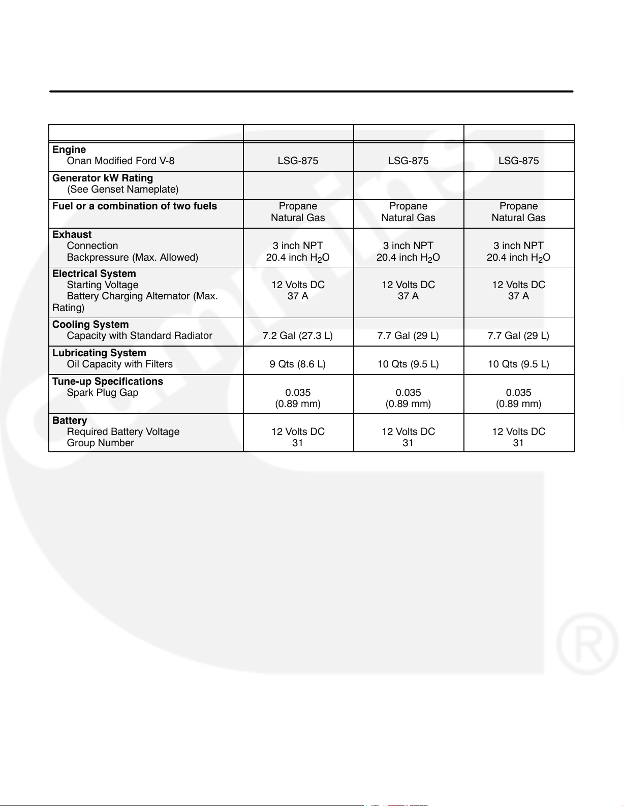
MODEL GGHB GGHC GGHD
Engine
Onan Modified Ford V-8
Generator kW Rating
(See Genset Nameplate)
Fuel or a combination of two fuels Propane
Exhaust
Connection
Backpressure (Max. Allowed)
Electrical System
Starting Voltage
Battery Charging Alternator (Max.
Rating)
Cooling System
Capacity with Standard Radiator
Lubricating System
Oil Capacity with Filters
Tune-up Specifications
Spark Plug Gap
Battery
Required Battery Voltage
Group Number
LSG-875 LSG-875 LSG-875
Natural Gas
3 inch NPT
20.4 inch H
12 Volts DC
37 A
7.2 Gal (27.3 L) 7.7 Gal (29 L) 7.7 Gal (29 L)
9 Qts (8.6 L) 10 Qts (9.5 L) 10 Qts (9.5 L)
0.035
(0.89 mm)
12 Volts DC
31
Propane
Natural Gas
3 inch NPT
O
2
20.4 inch H
12 Volts DC
37 A
0.035
(0.89 mm)
12 Volts DC
31
O
2
Propane
Natural Gas
3 inch NPT
20.4 inch H
12 Volts DC
37 A
0.035
(0.89 mm)
12 Volts DC
31
O
2
2-1
Page 9

2-2
Page 10
3. Operation (Detector Control)
GENERAL
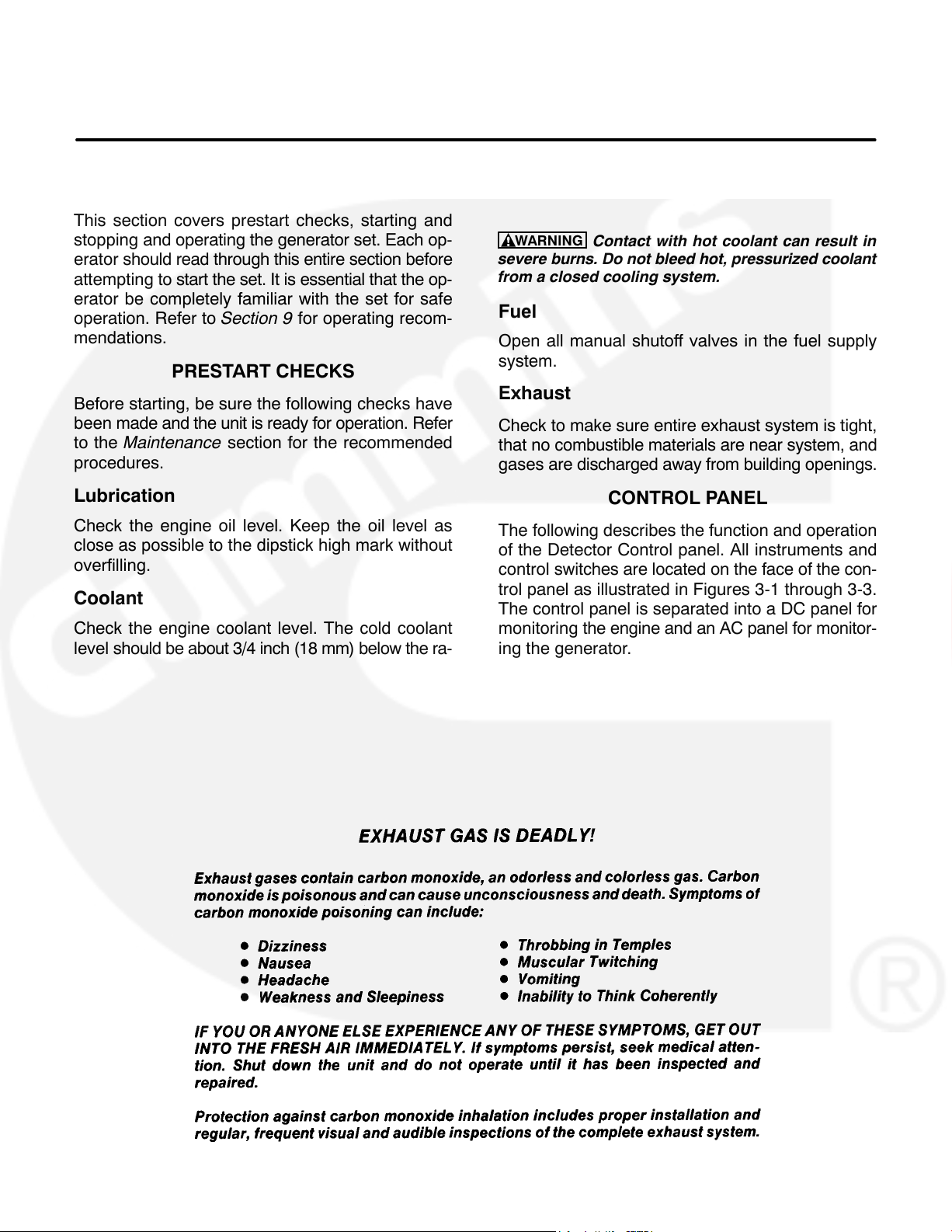
This section covers prestart checks, starting and
stopping and operating the generator set. Each op-
erator should read through this entire section before
attempting to start the set. It is essential that the op-
erator be completely familiar with the set for safe
operation. Refer to Section 9 for operating recom-
mendations.
PRESTART CHECKS
Before starting, be sure the following checks have
been made and the unit is ready for operation. Refer
to the Maintenance section for the recommended
procedures.
Lubrication
Check the engine oil level. Keep the oil level as
close as possible to the dipstick high mark without
overfilling.
Coolant
Check the engine coolant level. The cold coolant
level should be about 3/4 inch (18 mm) below the ra-
diator cap lower sealing surface. Do not check while
the engine is hot.
WARNING
severe burns. Do not bleed hot, pressurized coolant
from a closed cooling system.
Contact with hot coolant can result in
Fuel
Open all manual shutoff valves in the fuel supply
system.
Exhaust
Check to make sure entire exhaust system is tight,
that no combustible materials are near system, and
gases are discharged away from building openings.
CONTROL PANEL
The following describes the function and operation
of the Detector Control panel. All instruments and
control switches are located on the face of the con-
trol panel as illustrated in Figures 3-1 through 3-3.
The control panel is separated into a DC panel for
monitoring the engine and an AC panel for monitor-
ing the generator.
3-1
Page 11
OIL PRESSURE
GAUGE
PANEL LAMP
RUN/STOP/REMOTE
SWITCH
COOLANT
TEMPERATURE
GAUGE
DC VOLTMETER
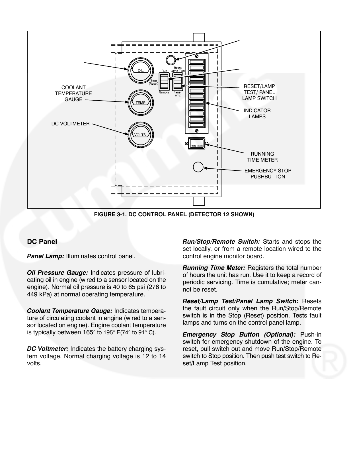
FIGURE 3-1. DC CONTROL PANEL (DETECTOR 12 SHOWN)
DC Panel
Panel Lamp: Illuminates control panel.
RESET/LAMP
TEST/ PANEL
LAMP SWITCH
INDICATOR
LAMPS
RUNNING
TIME METER
EMERGENCY STOP
PUSHBUTTON
Run/Stop/Remote Switch: Starts and stops the
set locally, or from a remote location wired to the
control engine monitor board.
Oil Pressure Gauge: Indicates pressure of lubri-
cating oil in engine (wired to a sensor located on the
engine). Normal oil pressure is 40 to 65 psi (276 to
449 kPa) at normal operating temperature.
Coolant Temperature Gauge: Indicates tempera-
ture of circulating coolant in engine (wired to a sen-
sor located on engine). Engine coolant temperature
is typically between 165
° to 195° F(74° to 91° C).
DC Voltmeter: Indicates the battery charging sys-
tem voltage. Normal charging voltage is 12 to 14
volts.
Running Time Meter: Registers the total number
of hours the unit has run. Use it to keep a record of
periodic servicing. Time is cumulative; meter can-
not be reset.
Reset/Lamp Test/Panel Lamp Switch: Resets
the fault circuit only when the Run/Stop/Remote
switch is in the Stop (Reset) position. Tests fault
lamps and turns on the control panel lamp.
Emergency Stop Button (Optional): Push-in
switch for emergency shutdown of the engine. To
reset, pull switch out and move Run/Stop/Remote
switch to Stop position. Then push test switch to Re-
set/Lamp Test position.
3-2
Page 12
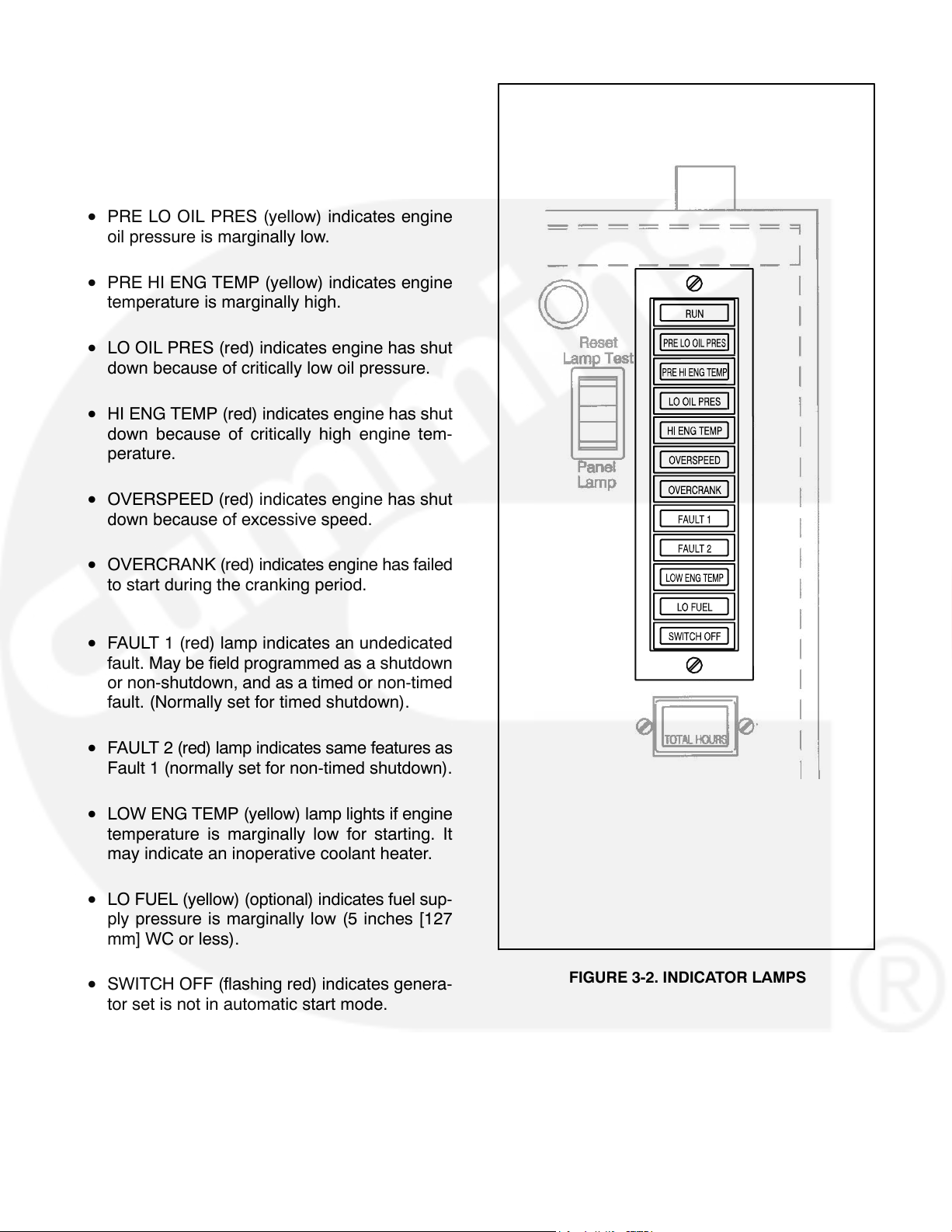
Indicator Lamps: The control panel has twelve indicator lamps which are described as follows:
• RUN (green) lamp comes on when starter cir-
cuit opens after set starting.
• PRE LO OIL PRES (yellow) indicates engine
oil pressure is marginally low.
• PRE HI ENG TEMP (yellow) indicates engine
temperature is marginally high.
• LO OIL PRES (red) indicates engine has shut
down because of critically low oil pressure.
• HI ENG TEMP (red) indicates engine has shut
down because of critically high engine tem-
perature.
• OVERSPEED (red) indicates engine has shut
down because of excessive speed.
• OVERCRANK (red) indicates engine has failed
to start during the cranking period.
• FAULT 1 (red) lamp indicates an undedicated
fault. May be field programmed as a shutdown
or non-shutdown, and as a timed or non-timed
fault. (Normally set for timed shutdown).
• FAULT 2 (red) lamp indicates same features as
Fault 1 (normally set for non-timed shutdown).
• LOW ENG TEMP (yellow) lamp lights if engine
temperature is marginally low for starting. It
may indicate an inoperative coolant heater.
• LO FUEL (yellow) (optional) indicates fuel sup-
ply pressure is marginally low (5 inches [127
mm] WC or less).
• SWITCH OFF (flashing red) indicates genera-
tor set is not in automatic start mode.
FIGURE 3-2. INDICATOR LAMPS
3-3
Page 13
AC VOLTMETER
AC AMMETER
FREQUENCY/
RPM METER
UPPER AND LOWER
SCALE INDICATOR
A−C VOLTS
VOLTAGE
ADJUST
A−C AMPERES
EXCITATION
FIELD BREAKER
RPM
HERTZ
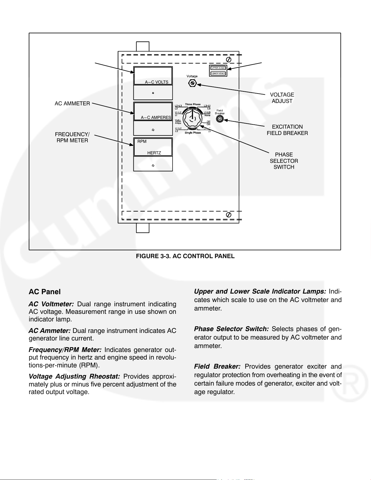
FIGURE 3-3. AC CONTROL PANEL
AC Panel
AC Voltmeter: Dual range instrument indicating
AC voltage. Measurement range in use shown on
indicator lamp.
AC Ammeter: Dual range instrument indicates AC
generator line current.
Frequency/RPM Meter: Indicates generator out-
put frequency in hertz and engine speed in revolu-
tions-per-minute (RPM).
Voltage Adjusting Rheostat: Provides approxi-
mately plus or minus five percent adjustment of the
rated output voltage.
PHASE
SELECTOR
SWITCH
Upper and Lower Scale Indicator Lamps: Indi-
cates which scale to use on the AC voltmeter and
ammeter.
Phase Selector Switch: Selects phases of gen-
erator output to be measured by AC voltmeter and
ammeter.
Field Breaker: Provides generator exciter and
regulator protection from overheating in the event of
certain failure modes of generator, exciter and volt-
age regulator.
3-4
Page 14
GENERATOR AC VOLTAGE REGULATOR
The solid-state regulator controls AC output voltage
from the generator at a predetermined level regardless of load. Refer to the GG Series Specification
Sheet for the voltage regulation and random voltage variation specifications.
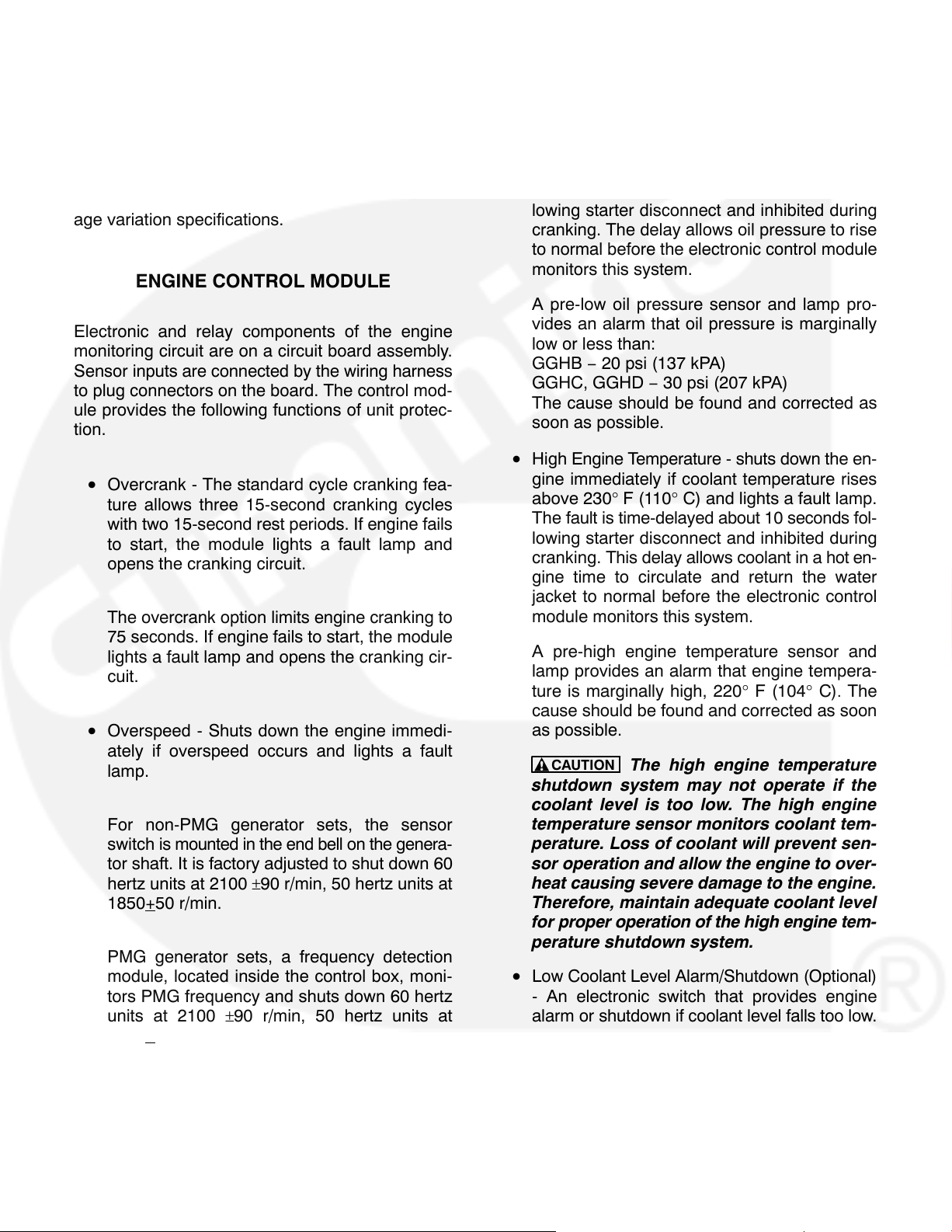
ENGINE CONTROL MODULE
Electronic and relay components of the engine
monitoring circuit are on a circuit board assembly.
Sensor inputs are connected by the wiring harness
to plug connectors on the board. The control mod-
ule provides the following functions of unit protec-
tion.
• Overcrank - The standard cycle cranking fea-
ture allows three 15-second cranking cycles
with two 15-second rest periods. If engine fails
to start, the module lights a fault lamp and
opens the cranking circuit.
The overcrank option limits engine cranking to
75 seconds. If engine fails to start, the module
lights a fault lamp and opens the cranking cir-
cuit.
• Overspeed - Shuts down the engine immedi-
ately if overspeed occurs and lights a fault
lamp.
For non-PMG generator sets, the sensor
switch is mounted in the end bell on the genera-
tor shaft. It is factory adjusted to shut down 60
hertz units at 2100
1850+
PMG generator sets, a frequency detection
module, located inside the control box, moni-
tors PMG frequency and shuts down 60 hertz
units at 2100
1850+
50 r/min.
50 r/min.
±90 r/min, 50 hertz units at
±90 r/min, 50 hertz units at
• Low Oil Pressure - Shuts down the engine im-
mediately and lights a fault lamp if oil pressure
drops below:
GGHB − 14 psi (97 kPA)
GGHC, GGHD − 25 psi (195 kPA)
The fault is time-delayed about 10 seconds following starter disconnect and inhibited during
cranking. The delay allows oil pressure to rise
to normal before the electronic control module
monitors this system.
A pre-low oil pressure sensor and lamp pro-
vides an alarm that oil pressure is marginally
low or less than:
GGHB − 20 psi (137 kPA)
GGHC, GGHD − 30 psi (207 kPA)
The cause should be found and corrected as
soon as possible.
• High Engine Temperature - shuts down the en-
gine immediately if coolant temperature rises
above 230° F (110° C) and lights a fault lamp.
The fault is time-delayed about 10 seconds fol-
lowing starter disconnect and inhibited during
cranking. This delay allows coolant in a hot en-
gine time to circulate and return the water
jacket to normal before the electronic control
module monitors this system.
A pre-high engine temperature sensor and
lamp provides an alarm that engine tempera-
ture is marginally high, 220° F (104° C)
cause should be found and corrected as soon
as possible.
CAUTION
shutdown system may not operate if the
coolant level is too low. The high engine
temperature sensor monitors coolant tem-
perature. Loss of coolant will prevent sen-
sor operation and allow the engine to over-
heat causing severe damage to the engine.
Therefore, maintain adequate coolant level
for proper operation of the high engine tem-
perature shutdown system.
The high engine temperature
. The
• Low Coolant Level Alarm/Shutdown (Optional)
- An electronic switch that provides engine
alarm or shutdown if coolant level falls too low.
It also turns on the fault lamp.
3-5
Page 15
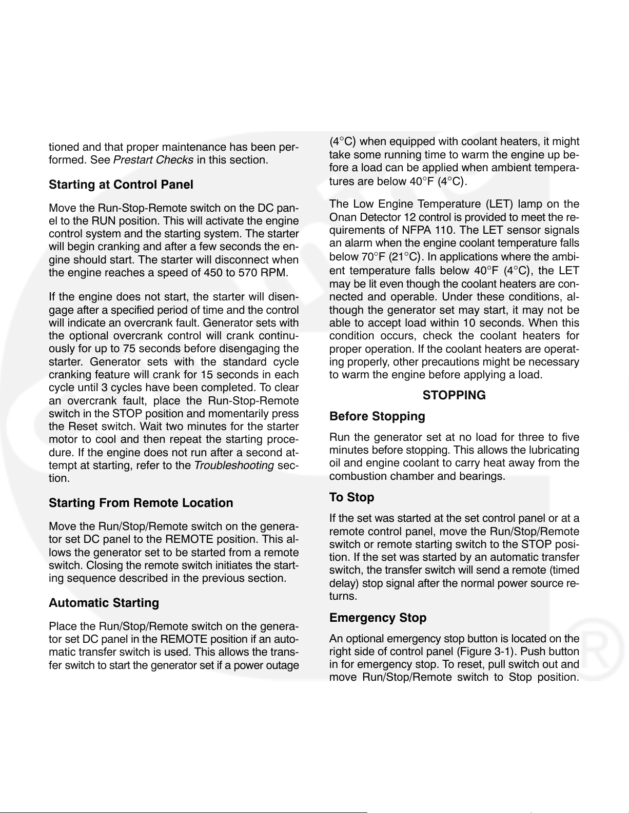
STARTING
The following sections cover the three systems
used to start the generator set.
Before starting the generator set, make sure that
exhaust and fuel fittings are tight and properly positioned and that proper maintenance has been per-
formed. See Prestart Checks in this section.
Starting at Control Panel
where the minimum ambient temperature is above
40
°F (4°C). NFPA also requires that the engine
coolant be maintained at a minimum of 90
and for most applications, accept the emergency
load in 10 seconds or less. Although most Onan
generator sets will start in temperatures below 40
°C) when equipped with coolant heaters, it might
(4
take some running time to warm the engine up be-
fore a load can be applied when ambient tempera-
tures are below 40
°F (4°C).
°F (32°C)
°F
Move the Run-Stop-Remote switch on the DC pan-
el to the RUN position. This will activate the engine
control system and the starting system. The starter
will begin cranking and after a few seconds the en-
gine should start. The starter will disconnect when
the engine reaches a speed of 450 to 570 RPM.
If the engine does not start, the starter will disen-
gage after a specified period of time and the control
will indicate an overcrank fault. Generator sets with
the optional overcrank control will crank continu-
ously for up to 75 seconds before disengaging the
starter. Generator sets with the standard cycle
cranking feature will crank for 15 seconds in each
cycle until 3 cycles have been completed. To clear
an overcrank fault, place the Run-Stop-Remote
switch in the STOP position and momentarily press
the Reset switch. Wait two minutes for the starter
motor to cool and then repeat the starting proce-
dure. If the engine does not run after a second at-
tempt at starting, refer to the Troubleshooting sec-
tion.
Starting From Remote Location
Move the Run/Stop/Remote switch on the genera-
tor set DC panel to the REMOTE position. This al-
lows the generator set to be started from a remote
switch. Closing the remote switch initiates the start-
ing sequence described in the previous section.
Automatic Starting
Place the Run/Stop/Remote switch on the genera-
tor set DC panel in the REMOTE position if an auto-
matic transfer switch is used. This allows the trans-
fer switch to start the generator set if a power outage
occurs and stop it when the power returns.
Cold Starting With Loads
In accordance with NFPA 110, Onan recommends
installing standby generator sets (life safety systems) equipped with coolant heaters in locations
The Low Engine Temperature (LET) lamp on the
Onan Detector 12 control is provided to meet the re-
quirements of NFPA 110. The LET sensor signals
an alarm when the engine coolant temperature falls
below 70
ent temperature falls below 40
may be lit even though the coolant heaters are con-
nected and operable. Under these conditions, al-
though the generator set may start, it may not be
able to accept load within 10 seconds. When this
condition occurs, check the coolant heaters for
proper operation. If the coolant heaters are operat-
ing properly, other precautions might be necessary
to warm the engine before applying a load.
°F (21°C). In applications where the ambi-
°F (4°C), the LET
STOPPING
Before Stopping
Run the generator set at no load for three to five
minutes before stopping. This allows the lubricating
oil and engine coolant to carry heat away from the
combustion chamber and bearings.
To Stop
If the set was started at the set control panel or at a
remote control panel, move the Run/Stop/Remote
switch or remote starting switch to the STOP posi-
tion. If the set was started by an automatic transfer
switch, the transfer switch will send a remote (timed
delay) stop signal after the normal power source re-
turns.
Emergency Stop
An optional emergency stop button is located on the
right side of control panel (Figure 3-1). Push button
in for emergency stop. To reset, pull switch out and
move Run/Stop/Remote switch to Stop position.
Then push test switch to Reset/Lamp Test position.
Onan automatic transfer switches have as an op-
tion an exerciser that can be preset to provide regu-
lar exercise periods. Typically the exerciser can be
set for time of start, length of run, and day of week.
3-6
Page 16

4. Troubleshooting (Detector Control)
The generator set has sensors that continuously
monitor the engine for abnormal conditions, such as
low oil pressure or high coolant temperature. If
these conditions occur, the engine monitor acti-
vates a fault lamp, and may also stop the engine
(depending on the condition). If the generator set is
stopped for this reason, the operator may be able to
restart the set after making adjustments or correc-
tions. This section describes the fault condition sys-
tem, and suggests troubleshooting procedures.
The control has a single green light to indicate RUN,
four amber lights and seven red fault lights. The
control also has a terminal connection for an audi-
ble alarm, that sounds when a fault occurs.
SAFETY CONSIDERATIONS
High voltages are present inside the control box and
generator output box when the set is running. Do
not open the control box or generator output box
while the set is running.
WARNING
nents can cause electrocution, resulting in se-
vere personal injury or death. Keep control and
output box covers in place during troubleshoot-
ing.
When troubleshooting a set that is shut down, make
certain the generator set cannot be accidentally re-
started. Place the Run/Stop/Remote switch in the
STOP position and remove the negative battery ca-
ble from the set starting battery.
CAUTION
charger from its AC source before disconnect-
ing the battery cables. Otherwise, disconnect-
ing the cables can result in voltage spikes high
enough to damage the DC control circuits of the
set.
Contacting high voltage compo-
Always disconnect a battery
WARNING
set while working on it can cause severe per-
sonal injury or death. Prevent accidental start-
ing by disconnecting the starting battery cables
(negative [−] first).
Make certain battery area has been well venti-
lated before servicing battery, especially if a
battery charger has been connected. Arcing
can ignite explosive hydrogen gas given off by
batteries, causing severe personal injury. Arc-
ing can occur when cable is removed or re-at-
tached, or when negative (−) battery cable is
connected and a tool used to connect or discon-
nect positive (+) battery cable touches frame or
other grounded metal part of the set.
When a fault lamp turns on during operation, follow
the procedures listed below to locate and correct
the problem. For any symptom not listed, contact an
authorized service center for assistance.
Accidental starting of the generator
Resetting the Control
The external alarm and fault lamp may be deacti-
vated by moving the Run/Stop/Remote switch to
the Stop position and pressing the Reset/Lamp
Test/Panel Lamp switch. Locate the problem and
correct it before restarting the set. While pressing
the Reset/Lamp Test/Panel Lamp switch, make cer-
tain that all lamps light.
Line Circuit Breaker (Optional)
The optional line circuit breaker mounts on the gen-
erator output box. If the load exceeds the generator
current rating, the line circuit breaker will open, pre-
venting the generator from being overloaded. If the
circuit breaker trips, locate the source of the over-
load and correct as necessary. Manually reset the
breaker to reconnect the load to the generator.
4-1
Page 17

TABLE 4-1. TROUBLESHOOTING
Many troubleshooting procedures present hazards which can result in severe personal
injury or death. Only qualified service personnel with knowledge of fuels, electricity, and machinery
hazards should perform service procedures. Review safety precautions on pages iii and iv.
SYMPTOM CORRECTIVE ACTION
1. Green RUN lamp lights following engine
startup.
2. PRE HI ENGINE TEMP lamp lights. En-
gine continues to operate.
3. HI ENG TEMP lamp lights. Engine shuts
down.
1. Indicates all engine systems are normal. No correc-
tive action required.
2. Indicates engine has begun to overheat and engine
temperature has risen to approximately 220
C). If generator is powering non-critical and critical
loads and cannot be shut down, use the following:
a. Reduce load if possible by turning off non-critical
loads.
b. Check air inlets and outlets and remove any ob-
structions to airflow.
If engine can be stopped, follow procedure in
step 3.
3. Indicates engine has overheated (engine tempera-
ture has risen above 230
low (sets with coolant level sensor). Allow engine to
cool down completely before proceeding with the fol-
lowing checks:
a. Check coolant level and replenish if low. Look for
possible coolant leakage points and repair if
necessary.
°F/110°C) or coolant level is
°F (104°
4. PRE LO OIL PRES lamp lights. Engine
continues to operate.
b. Check for obstructions to cooling airflow and
correct as necessary.
c. Check for a slipping fan belt and tighten if loose.
d. Reset control and restart after locating and cor-
recting problem. Contact an authorized service
center for service if none of the above.
4. Indicates engine oil pressure has dropped to:
GGHB − 20 psi (137 kPA)
GGHC, GGHD − 30 psi (207 kPA)
If generator is powering critical loads and cannot be
shut down, wait until next shutdown period and then
follow step 5 procedure. If engine can be stopped, fol-
low procedures in step 5.
4-2
Page 18

TABLE 4-1. TROUBLESHOOTING (continued)
Many troubleshooting procedures present hazards which can result in severe personal
injury or death. Only qualified service personnel with knowledge of fuels, electricity, and machinery
hazards should perform service procedures. Review safety precautions on pages iii and iv.
SYMPTOM CORRECTIVE ACTION
5. LO OIL PRES lamp lights. Engine shuts
down. NOTE: See also step 6.
6. OVERCRANK lamp lights and engine
stops cranking.
or
Engine runs, shuts down, and LO OIL
PRES lamp lights..
7. OVERSPEED lamp lights and the en-
gine shuts down.
5. Indicates engine oil pressure has dropped to:
GGHB − 14 psi (97 kPA)
GGHC, GGHD − 25 psi (195 kPA)
Check oil level, lines and filters. If oil system is OK but
oil level is low, replenish. Reset control and restart.
Contact an authorized service center if oil pressure is
not in the range of 40 to 65 psi (276 to 449 kPa).
6. Indicates possible fuel system problem.
a. Open any closed fuel shutoff valve.
b. Check for dirty or plugged air filter and replace if
necessary (see Maintenance section).
c. Gaseous fuel delivery to the set is inadequate.
Contact an authorized service center for service.
d. Reset the control and restart after correcting the
problem. Contact an authorized service center
for service if none of the above.
7. Indicates engine has exceeded normal operating
speed. Contact an authorized service center for serv-
ice.
8. SWITCH OFF lamp flashes. 8. Indicates Run/Stop/Remote switch is in the Stop po-
sition which will prevent automatic starting if an auto-
matic transfer switch is used. Move the Run/Stop/Re-
mote switch to the Remote position for automatic
starting.
9. LO ENG TEMP lamp lights. Set is in
standby mode but is not operating.
(Lamp lights when engine coolant tem-
perature is 70
the lamp goes out after the engine
warms up, there should be no cause for
alarm even during initial generator set
operation.)
° F (21° C) or lower. Since
9. Indicates engine coolant heater is not operating, not
circulating coolant or ambient temperature too cold
for heater to keep up with demand. Check for the fol-
lowing conditions:
a. Coolant heater not connected to power supply.
Check for blown fuse or disconnected heater
cord and correct as required.
b. Check for low coolant level and replenish if re-
quired. Look for possible coolant leakage points
and repair as required.
c. Contact an authorized service center for service
if none of the above.
4-3
Page 19

TABLE 4-1. TROUBLESHOOTING (continued)
Many troubleshooting procedures present hazards which can result in severe personal
injury or death. Only qualified service personnel with knowledge of fuels, electricity, and machinery
hazards should perform service procedures. Review safety precautions on pages iii and iv.
SYMPTOM
10. The FAULT 1 or FAULT 2 fault lamp
lights. Engine shuts down immediately,
engine runs for several seconds and
then shuts down, or engine continues to
run.
11. The LOW FUEL fault lamp lights. En-
gine continues to run or is in standby
mode.
12. Fault lamp lights but no fault exists. En-
gine gauges show oil pressure, engine
temperature, and frequency (speed) are
within normal limits.
13. Engine starts from generator control
panel but will not start automatically or
from a remote panel. (Note: The Run/
Stop/Remote switch must be in the Re-
mote position for automatic or remote
starting).
CORRECTIVE ACTION
10. The standard undesignated fault functions are pro-
grammed to shut down the set when a fault is sensed.
Fault 1 is time delayed while Fault 2 is immediate.
The nature of the fault is an optional selection that is
determined when the set installation is designed.
The undesignated fault functions may also be pro-
grammed for non-shutdown or non-time delay.
11. Indicates fuel supply pressure is marginally low (5
inches [127 mm] WC or less). Check for partially
closed shutoff valve, empty propane supply tank. For
natural gas fueled sets, check with the gas utility.
12. The monitor board or a sensor may be at fault. Con-
tact an authorized service center for service.
13. Remote circuit breaker is tripped. Reset breaker and
restart. Contact an authorized service center if
breaker trips after resetting.
14. Engine will not crank.
14. Indicates possible fault with control or starting sys-
tem. Check for the following conditions:
a. Fault lamp on. Correct fault and reset control.
b. Poor battery cable connections. Clean the bat-
tery cable terminals and tighten all connections.
c. Discharged or defective battery. Recharge or re-
place the battery.
d. Emergency stop button (if equipped) pushed in.
To reset, pull switch out and move Run/Stop/Re-
mote switch to Stop position. Then push test
switch to Reset/ Lamp position.
e. Contact an authorized service center if none of
the above.
4-4
Page 20

TABLE 4-1. TROUBLESHOOTING (continued)
Many troubleshooting procedures present hazards which can result in severe personal
injury or death. Only qualified service personnel with knowledge of fuels, electricity, and machinery
hazards should perform service procedures. Review safety precautions on pages iii and iv.
SYMPTOM
15. No AC output voltage.
16. RUN or fault lamp(s) does not light when
Lamp Test switch is engaged.
17. Green RUN lamp does not light follow-
ing engine startup.
CORRECTIVE ACTION
15. Field breaker is tripped. Reset breaker. Contact an
authorized service center if voltage buildup causes
breaker to trip.
16. Contact an authorized service center for assistance.
17. Indicates possible Start/Disconnect relay failure.
Contact an authorized service center for assistance.
4-5
Page 21

4-6
Page 22

5. Operation (Sentinel Control)
GENERAL
This section covers prestart checks, starting and
stopping and operating the generator set. Each op-
erator should read through this entire section before
attempting to start the set. It is essential that the op-
erator be completely familiar with the set for safe
operation. Refer to Section 9 for operating recom-
mendations.
PRESTART CHECKS
Before starting, be sure the following checks have
been made and the unit is ready for operation. Refer
to the Maintenance section for the recommended
procedures.
Lubrication
Check the engine oil level. Keep the oil level as
close as possible to the dipstick high mark without
overfilling.
Coolant
Check the engine coolant level. The cold coolant
level should be about 3/4 inch (18 mm) below the ra-
diator cap lower sealing surface. Do not check while
the engine is hot.
WARNING
in severe burns. Do not bleed hot, pressurized
coolant from a closed cooling system.
Contact with hot coolant can result
Fuel
Check the fuel supply and open all manual shutoff
valves in the fuel supply system.
Exhaust
Check to make sure entire exhaust system is tight,
that no combustible materials are near system, and
gases are discharged away from building openings.
CONTROL PANEL
The following describes the function and operation
of the Sentinel control. All instruments and control
switches are located on the face of the control panel
as illustrated in Figure 5-1.
5-1
Page 23

AC VOLTMETER
AC AMMETER
PHASE
SELECTOR
SWITCH
FREQUENCY/
RPM METER
FIELD BREAKER
(EXCITATION)
VOLTAGE
ADJUST
RUN/STOP/REMOTE
SWITCH
20A CONTROL
FUSE
COMMON FAULT
CIRCUIT BREAKER
RUNNING
TIME METER
AC CONTROL DC CONTROL
FIGURE 5-1. SENTINEL CONTROL PANEL
DC Control
Run/Stop/Remote Switch: Starts and stops the
set locally, or from a remote location wired to the
control.
Running Time Meter: Registers the total number
of hours the unit has run. Use it to keep a record of
periodic servicing. Time is cumulative; meter can-
not be reset.
20A Control Fuse: Protects control components
and wiring from current overload.
Common Fault Circuit Breaker: The common
fault circuit breaker shuts down the engine when
any fault shutdown sensor activates. Fault shut-
down is indicated when the breaker reset button ex-
tends out past normal. Push the button to restore
operation (after the engine has been properly serviced).
The standard fault shutdowns are low oil pressure,
high engine temperature or overcrank. Overspeed
is optional.
AC Control
AC Voltmeter (Optional): Dual range instrument
indicating AC voltage. Measurement range in use
shown on indicator lamp.
AC Ammeter (Optional): Dual range instrument
indicates AC generator line current.
Frequency/RPM Meter (Optional): Indicates gen-
erator output frequency in hertz and engine speed
in revolutions-per-minute (RPM).
Voltage Adjusting Rheostat (Optional): Provides
approximately plus or minus five percent adjust-
ment of the rated output voltage.
Phase Selector Switch (Optional): Selects
phases of generator output to be measured by AC
voltmeter and ammeter.
Field Breaker (Excitation): Provides generator
exciter and regulator protection from overheating in
the event of certain failure modes of generator, exciter and voltage regulator.
5-2
Page 24

GENERATOR AC VOLTAGE REGULATOR
The solid-state regulator controls AC output voltage
from the generator at a predetermined level regardless of load. Refer to the GG Series Specification
Sheet for the voltage regulation and random voltage variation specifications.
ENGINE MONITORING
Electronic and relay components of the engine
monitoring circuit are mounted inside the control
box. An optional Dry Contact Module (DCM) can
also be installed in the control box to enable remote
monitoring of these components. The components
provide the following functions of unit protection.
Note: Refer to the Installation Manual for a functional
description of the Dry Contact Module option.
• Overcrank - Limits engine cranking to 60 se-
conds. If engine fails to start, the Fault Breaker
trips and opens the cranking circuit.
• Low Coolant Level (optional w/DCM) - Shuts
down the engine immediately if coolant level
falls too low. Fault condition cannot be cleared
until sensor detects coolant in radiator.
• Low Fuel Pressure (optional w/DCM) - Indi-
cates fuel supply pressure is marginally low (5
inches [127 mm] WC or less). Used only in
single fuel systems. (Remote panel must be at-
tached to control to monitor this error.)
CAUTION
down system may not operate if the coolant
level is too low. The high engine temperature
sensor monitors coolant temperature. Loss of
coolant will prevent sensor operation and allow
the engine to overheat causing severe damage
to the engine. Therefore, maintain adequate
coolant level for proper operation of the high
engine temperature shutdown system.
The high engine temperature shut-
STARTING
• Overspeed (optional) - Shuts down the engine
immediately and trips the common fault circuit
breaker if overspeed occurs. The sensor
switch is mounted in the end bell on the genera-
tor shaft for non-PMG sets. PMG sets, a fre-
quency detection module, located inside the
control box, monitors PMG frequency. The shut
down limits are: 60 hertz units at 2100
min, 50 hertz units at 1850+
50 r/min.
±90 r/
• Low Oil Pressure - Shuts down the engine im-
mediately and trips the common fault circuit
breaker if oil pressure drops below:
GGHB − 14 psi (97 kPA)
GGHC, GGHD − 25 psi (195 kPA)
The fault is time-delayed about 10 seconds fol-
lowing starter disconnect and inhibited during
cranking. The delay allows oil pressure to rise
to normal before the electronic control module
monitors this system.
• High Engine Temperature - Shuts down the en-
gine immediately if coolant temperature rises
above 230° F (110° C) and trips the common
fault circuit breaker. Fault condition cannot be
cleared until sensor detects coolant tempera-
ture of lower than 220° F (104° C)
.
The following sections cover the three systems
used to start the generator set.
Before starting the generator set, make sure that
exhaust and fuel fittings are tight and properly posi-
tioned and that proper maintenance has been per-
formed. See Prestart Checks in this section.
Starting at Control Panel
Move the Run-Stop-Remote switch on the DC pan-
el to the RUN position. This will activate the engine
control system and the starting system. The starter
will begin cranking and after a few seconds the en-
gine should start. The starter will disconnect when
the engine reaches a speed of 450 to 570 RPM.
If the engine does not start, the starter will disen-
gage after 60 seconds and the control will indicate
an overcrank fault. To clear an overcrank fault,
place the Run-Stop-Remote switch in the STOP po-
sition and reset the common fault circuit breaker.
Wait two minutes for the starter motor to cool and
then repeat the starting procedure. If the engine
does not run after a second attempt at starting, refer
to the Troubleshooting (Sentinel Control) section.
5-3
Page 25

Starting From Remote Location
Move the Run/Stop/Remote switch on the generator set DC panel to the REMOTE position. This allows the generator set to be started from a remote
switch. Closing the remote switch initiates the starting sequence described in the previous section.
Automatic Starting
Engine coolant heaters are available for easier
starting in cold weather. Make sure the voltage of
the separate power source is correct for the coolant
heater element rating.
CAUTION
heater, make sure the cooling system is full be-
fore applying power to the heater.
To avoid damage to the coolant
STOPPING
Place the Run/Stop/Remote switch on the genera-
tor set DC panel in the REMOTE position if an auto-
matic transfer switch is used. This allows the trans-
fer switch to start the generator set if a power outage
occurs and stop it when the power returns.
Cold Starting With Loads
Change the engine oil if it is not of the viscosity rec-
ommended for the ambient temperature (Figure
7-1).
To prevent engine coolant from freezing, make sure
the coolant is a 50/50 mixture of anti-freeze and wa-
ter.
Before Stopping
Run the generator set at no load for three to five
minutes before stopping. This allows the lubricating
oil and engine coolant to carry heat away from the
combustion chamber and bearings.
To Stop
If the set was started at the set control panel or at a
remote control panel, move the Run/Stop/Remote
switch or remote starting switch to the STOP posi-
tion. If the set was started by an automatic transfer
switch, the transfer switch will send a remote (timed
delay) stop signal after the normal power source re-
turns.
5-4
Page 26

6. Troubleshooting (Sentinel Control)
The generator set has sensors that continuously
monitor the engine for abnormal conditions, such as
low oil pressure or high coolant temperature. If
these conditions occur, the common fault circuit
breaker trips, and the engine shuts down. After the
problem is corrected, reset the common fault circuit
breaker to restart the generator set. This section de-
scribes the fault condition system, and suggests
troubleshooting procedures.
SAFETY CONSIDERATIONS
High voltages are present inside the control box and
generator output box when the set is running. Do
not open the control box or generator output box
while the set is running.
WARNING
nents can cause electrocution, resulting in se-
vere personal injury or death. Keep control and
output box covers in place during troubleshoot-
ing.
When troubleshooting a set that is shut down, make
certain the generator set cannot be accidentally re-
started. Place the Run/Stop/Remote switch in the
STOP position and remove the negative battery ca-
ble from the set starting battery.
Contacting high voltage compo-
CAUTION
charger from its AC source before disconnect-
ing the battery cables. Otherwise, disconnect-
ing the cables can result in voltage spikes high
enough to damage the DC control circuits of the
set.
WARNING
set while working on it can cause severe per-
sonal injury or death. Prevent accidental start-
ing by disconnecting the starting battery cables
(negative [−] first).
Make certain battery area has been well venti-
lated before servicing battery, especially if a
battery charger has been connected. Arcing
can ignite explosive hydrogen gas given off by
batteries, causing severe personal injury. Arc-
ing can occur when cable is removed or re-at-
tached, or when negative (−) battery cable is
connected and a tool used to connect or discon-
nect positive (+) battery cable touches frame or
other grounded metal part of the set.
When a fault condition occurs during operation, fol-
low the procedures in Table 6-1 to locate and cor-
rect the problem. For any symptom not listed, con-
tact an authorized service center for assistance.
Always disconnect a battery
Accidental starting of the generator
6-1
Page 27

TABLE 6-1. TROUBLESHOOTING
Many troubleshooting procedures present hazards which can result in severe personal
injury or death. Only qualified service personnel with knowledge of fuels, electricity, and machinery
hazards should perform service procedures. Review safety precautions on pages iii and iv.
SYMPTOM CORRECTIVE ACTION
1. Engine will not crank. 1. Indicates possible fault with control or starting system.
Check for the following conditions:
a. Correct fault and reset common fault circuit break-
er.
b. Poor battery cable connections. Clean the battery
cable terminals and tighten all connections.
c. Discharged or defective battery. Recharge or re-
place the battery.
d. Replace the control circuit fuse (located inside the
control panel) if it has blown.
2. The engine cranks, but does not start.
3. The engine shuts down due to high en-
gine temperature or low coolant level.
The Fault Shutdown is being indicated
by the fault circuit breaker reset button
(extended out).
2. Indicates possible fuel system problem.
a. Check for empty fuel tank, fuel leaks, or plugged
fuel lines and correct as required.
b. Check for dirty or plugged air filter and replace if
necessary (see Maintenance section).
c. Reset the tripped common fault circuit breaker and
restart after correcting the problem. Contact an
authorized service center for service if none of the
above.
3. Indicates engine has overheated (engine temperature
has risen above 230
down completely before proceeding with the following
checks:
a. Check coolant level and replenish if low. Look for
possible coolant leakage points and repair if neces-
sary.
b. Check for obstructions to cooling airflow and cor-
rect as necessary.
° F/110° C). Allow engine to cool
c. Check for a slipping fan belt and tighten if loose.
d. Reset the tripped common fault circuit breaker.
Contact an authorized service center for service if
none of the above.
6-2
Page 28

TABLE 6-1. TROUBLESHOOTING (continued)
Many troubleshooting procedures present hazards which can result in severe personal
injury or death. Only qualified service personnel with knowledge of fuels, electricity, and machinery
hazards should perform service procedures. Review safety precautions on pages iii and iv.
SYMPTOM
4. Engine shuts down due to low oil pres-
sure. The Fault Shutdown is being indi-
cated by the fault circuit breaker reset
button (extended out).
5. The engine shuts down due to over-
speed. The Fault Shutdown is being in-
dicated by the fault circuit breaker reset
button (extended out).
6. The engine shuts down due to low cool-
ant level. The Fault Shutdown is being
indicated by the fault circuit breaker re-
set button (extended out).
7. The engine shuts down due any of five
faults but remote monitor device does
not detect fault.
CORRECTIVE ACTION
4. Indicates engine oil pressure has dropped to:
GGHB − 14 psi (97 kPA)
GGHC, GGHD − 25 psi (195 kPA)
Check oil level, lines and filters. If oil system is OK but
oil level is low, replenish. Reset the tripped common
fault circuit breaker. Contact an authorized service
center if oil pressure is not in the range of 40 to 65 psi
(276 to 449 kPa).
5. Indicates engine has exceeded normal operating
speed. Contact an authorized service center for service.
6. Indicates low coolant level. Replenish coolant and
look for possible coolant leakage points and repair as
required.
7. Indicates possible fault with control or external wiring.
8. Engine starts from generator control
panel but will not start automatically or
from a remote panel. (Note: The Run/
Stop/Remote switch must be in the Re-
mote position for automatic or remote
starting).
8. Remote circuit breaker is tripped. Reset breaker and
restart. Contact an authorized service center if
breaker trips after resetting.
6-3
Page 29

6-4
Page 30

7. Maintenance
GENERAL
Establish and adhere to a definite schedule for
maintenance and service based on the application
and severity of the environment. The table below
covers the recommended service intervals for a
generator set on STANDBY service. If the set will
be subjected to extreme operating conditions, the
service intervals should be reduced accordingly.
Some of the factors that can affect the maintenance
schedule are the following:
• Use for continuous duty (prime power)
• Extremes in ambient temperature
• Exposure to elements
• Exposure to salt water
• Exposure to windblown dust or sand.
Consult with an authorized Onan Distributor if the
generator set will be subjected to any extreme operating conditions and determine a suitable schedule
of maintenance. Use the running time meter to
keep an accurate log of all service performed for
warranty support. Perform all service at the time
period indicated or after the number of operating
hours indicted, whichever comes first. Use Table
7-1 to determine the maintenance required and
then refer to the sections that follow for the correct
service procedures.
WARNING
performing maintenance procedures can cause
serious personal injury or death. Place the Run-
Stop-Remote switch in the Stop position,dis-
connect battery charger from its AC source and
disconnect the negative(-) battery cable from
the battery terminal before beginning mainte-
nance procedures.
Accidental starting of the set while
7-1
Page 31

TABLE 7-1. PERIODIC MAINTENANCE SCHEDULE
OPERATIONAL FREQUENCY - HOURS
MAINTENANCE ITEMS 10 100 200 Yearly
General Set Inspection.
Check engine oil level
Check radiator coolant level
Check air cleaner (clean or replace as necessary)
Check battery electrolyte level
Check governor linkage
Change engine oil and filter
Check all hardware (fittings, clamps, fasteners, etc.)
Drain exhaust condensate trap
Adjust drive belt tension
Inspect or replace spark plugs x
Inspect coolant hoses and clamps
Inspect coolant heater hoses
Check coolant anti-freeze protection
Check AC generator and controls
Clean cooling system
1
x
1
x
1
x
2
x
3
x
2
x
2
x
4
x
x
5
x
6
x
6
x
x
x
x
x1- As noted or after every run.
2
- Perform more often in extremely dusty conditions
x
3
- Or every two weeks.
x
4
- Or every three months.
x
5
- Adjust to 1/2-inch (12.5 mm) depression between pulleys.
x
6
Replace if hard or brittle.
x
7-2
Page 32

GENERATOR SET INSPECTION
During operation, be alert for mechanical problems
that could create unsafe or hazardous conditions.
The following sections cover several areas that
should be frequently inspected for continued safe
operation.
Exhaust System
WARNING
personal injury or death by fire or explosion. Do
not permit any flame, cigarette, pilot light, arcing switch or equipment, or other ignition
source near the fuel system.
Ignition of fuel can cause severe
AC Electric System
Check the following while the generator set is oper-
ating; otherwise measure load lines L1, L2 and L3
using the appropriate AC meter.
With the generator set operating, inspect the entire
exhaust system visually and audibly, including the
exhaust manifold, muffler, and exhaust pipe. Check
for leaks at all connections, welds, gaskets, and
joints and also make sure that exhaust pipes are not
heating surrounding areas excessively. If any leaks
are detected, shut down the generator set and have
leaks corrected immediately.
WARNING
sult in serious personal injury or death. Be sure
deadly exhaust gas is piped outside and away
from windows, doors or other inlets to building.
Inhalation of exhaust gases can re-
Fuel System
With the generator set operating, inspect the fuel
supply lines, filters, and fittings for leaks. Check any
flexible sections for cuts, cracks and abrasions and
make sure they are not rubbing against anything
that could cause breakage. If any leaks are de-
tected, shut off fuel supply valves, shut down gener-
ator set and have them corrected immediately.
Frequency Meter: The generator frequency
should be stable and the reading should be the
same as the nameplate rating.
AC Voltmeter: Turn the phase selector switch to
each line-to-line phase selection shown on the volts
scale (L1-L2, L2-L3, and L3-L1). Read the AC volt-
meter using the upper or lower scale as indicated by
the scale indicator light. At no load, the line-to-line
voltage(s) should be the same as the set nameplate
rating.
AC Ammeter: Turn the phase selector switch to
each phase selection shown on the amps scale (L1,
L2 and L3). Read the ammeter using the upper or
lower scale as indicated by the scale indicator light.
At no load, the current readings should be zero.
With a load applied, each line current should be
about the same.
Fault Lamps: Push the Reset/Lamp switch on the
control panel. All indicator lamps should light. Con-
firm that all of the bulbs are on, then release the
switch. Have any bulbs that are burned out re-
placed.
7-3
Page 33

DC Electrical System
Check the terminals on the battery for clean and
tight connections. Loose or corroded connections
create resistance which can hinder starting. Clean
and reconnect the battery cables if loose. Always
disconnect both ends of the negative battery cable.
Reconnect one end of the cable to the negative bat-
tery terminal and the other end to ground. Following
this sequence will help to reduce arcing at the bat-
tery.
Make certain battery area has been well ventilated before servicing battery, especially if a
battery charger has been connected. Arcing
can ignite explosive hydrogen gas given off by
batteries, causing severe personal injury. Arcing can occur when cable is removed or re-attached, or when negative (−) battery cable is
connected and a tool used to connect or discon-
nect positive (+) battery cable touches frame or
other grounded metal part of the set.
CAUTION
Always disconnect a battery
charger from its AC source before disconnect-
ing the battery cables. Otherwise, disconnect-
ing the cables can result in voltage spikes high
enough to damage the DC control circuits of the
set.
WARNING
Accidental starting of the generator
set while working on it can cause severe per-
sonal injury or death. Prevent accidental start-
ing by disconnecting the starting battery cables
(negative [−] first).
Mechanical
With the generator set stopped, check for loose
belts and fittings, leaking gaskets and hoses, or any
signs of mechanical damage. If any problems are
found, have them corrected immediately. With the
set running, listen for any unusual noises that may
indicate mechanical problems and check the oil
pressure frequently. Investigate anything that indi-
cates possible mechanical problems.
7-4
Page 34

LUBRICATION SYSTEM
MODELS GGHC / GGHD
Before the initial start, check dipstick to be sure
crankcase is filled with oil. See Specifications sec-
tion for lubricating oil capacity.
Generator sets are shipped with oil and coolant add-
ed. Be sure to check these systems to make sure
they are at proper operating levels before starting.
Oil Recommendations
Refer to Figure 5-1 for the recommended oil viscos-
ity grades at various ambient temperatures. Oils
must conform to the American Petroleum Institute
(API) classification SH or SH/CD. When selecting
the oil viscosity, pick the grade that is right for the
lowest temperature expected. Oil that is too thick
can result in a lack of lubrication when the engine is
started. If the ambient temperature is consistently
below -13
°F (-25°C), use a SAE5W synthetic oil.
SAE 40
10W, 5W30
MODEL GGHB
SAE 30, 40
15W30
10W30, 10W40
5W30
FIGURE 5-1. OIL VISCOSITY
7-5
Page 35

Engine Oil Level
Check the engine oil level during engine shutdown
periods at the intervals specified in the Maintenance Table. The dipstick is stamped with FULL
and ADD to indicate the level of oil in the crankcase.
For accurate readings, shut off the engine and wait
approximately 10 minutes before checking the en-
gine oil level. This allows oil in the upper portion of
the engine to drain back into the crankcase.
Keep the oil level as near as possible to the FULL
mark on the dipstick. Remove the oil fill cap and add
oil of the same quality and brand when necessary.
ENGINE OIL
LEVEL DIPSTICK
CAUTION
Do not operate the engine with the
oil level below the ADD mark or above the FULL
mark. Overfilling can cause foaming or aeration
of the oil. Operation below the ADD mark can
cause loss of oil pressure.
Engine Oil Change
WARNING
termined that contact with used engine oil can
cause cancer or reproductive toxicity. Take care
to limit skin contact and the breathing of its va-
pors. Use rubber gloves and wash exposed
skin.
Run engine until thoroughly warm before draining
oil. Stop the set, place a pan under the drain outlet
and remove the oil drain plug or open the drain
valve. After the oil is completely drained, replace
the drain plug or close the drain valve. Refill with oil
of the correct API viscosity grade for the tempera-
ture conditions.
WARNING
it is spilled or splashed on skin. Keep fingers
and hands clear when removing the oil drain
plug and wear protective clothing.
State or federal agencies have de-
Hot crankcase oil can cause burns if
Oil Filter Change
FIGURE 7-2. OIL LEVEL DIPSTICK
FILTER
GASKET
FIGURE 7-3. ENGINE OIL FILTER
Spin off oil filter and discard it in accordance with lo-
cal environmental regulations. Thoroughly clean fil-
ter mounting surface. Apply a thin film of oil to filter
gasket and install new element. Spin element on by
hand until gasket just touches mounting pad and
then turn an additional 1/2 to 3/4 turn. Do not over-
tighten (Figure 7-3).
With oil in crankcase, start engine and check for
leaks around filter element. Retighten only as much
as necessary to eliminate leaks but do not overtighten.
7-6
Page 36

COOLING SYSTEM
The cooling system capacity of a standard unit with
set mounted radiator is shown in Specifications
section.
CAUTION
Never pour hot water into a cold engine or cold water into a hot engine. Doing so
can crack a head or cylinder block. Do not operate the generator set without water for even a
few minutes.
Generator sets are shipped with oil and coolant add-
ed. Be sure to check these systems to make sure
they are at proper operating levels before starting.
Coolant Requirements
Satisfactory engine coolant inhibits corrosion and if
necessary protects against freezing. Use a 50/50
coolant solution (50% pure water and 50% anti-
freeze). If temperatures below -37
° F (-38° C) are
possible, use a mixture of 65% antifreeze and 35%
water. Do not use an antifreeze that contains anti-
leak additives.
The water used for engine coolant should be clean,
low in mineral content and free of any corrosive
chemicals such as chloride, sulfate or acid. Use soft
water. Well water often contains lime and other ma-
terials which eventually can clog the radiator core
and reduce the cooling efficiency and can also
cause heater element failure.
Filling the Cooling System
Check to make sure that all drain cocks are closed
and all hose clamps secure. Remove the radiator
pressure cap and slowly fill the cooling system with
the recommended coolant.
When the engine is first started, remove the pressure cap and monitor the coolant level. As trapped
air is expelled from the system, the coolant level
may drop and additional coolant must be added.
Replace the pressure cap when the coolant level is
stable.
Coolant Level
Check the coolant level during shutdown periods at
the intervals shown in Table 7-1. Remove the radia-
tor cap after allowing the engine to cool and if nec-
essary, add coolant until the level is near the top of
the radiator.
WARNING
in severe burns. Allow cooling system to cool
before releasing pressure and removing radia-
tor cap.
CAUTION
will shut down engine in an overheat condition
only if coolant is sufficiently high to physically
contact shutdown switch. Loss of coolant will
allow engine to overheat without protection of
shutdown device and cause severe damage to
the engine. It is therefore imperative that ade-
quate engine levels be maintained to provide
operational integrity of the cooling system and
for engine coolant overheat shutdown protec-
tion.
Contact with hot coolant can result
High Engine Temperature Cutoff
7-7
Page 37

Draining and Flushing
WARNING
Some coolant is toxic. Keep away
from children and animals. Follow local environmental regulations for disposal.
To maintain adequate corrosion protection and remove rust and scale deposits, drain and flush radiator at the recommended interval.
CAUTION
The heater element will burn out if
engine coolant is removed with heater con-
nected to power source.
Disconnect engine coolant heater from power
source (if equipped).
Allow the engine to cool and then remove radiator
pressure cap. Open the radiator drain cock and re-
move the water drain plugs (one on each side of en-
gine). When the coolant is drained, place the end of
a water hose into the radiator filler and turn on water
supply. Regulate the flow of water into the radiator
until it is equal to the outflow from drain openings.
Continue flushing until outflow from drains is clear
of rust sediment.
If engine is equipped with engine coolant heater,
drain coolant by removing hose and clamp from bot-
tom of heater.
Replace the water drain plugs and close the radia-
tor drain cock when flushing is complete. Refill the
cooling system with the recommended coolant (re-
fer to Filling the Cooling System).
With cooling system properly filled and the engine
has been run, connect heater plug to receptacle.
DRAIN
DRAIN PLUG
(FAR SIDE)
FIGURE 7-4. DRAIN PLUG LOCATIONS
PLUG
7-8
Page 38

AIR FILTER
Remove wing nut in center of filter cover. Remove
cover and filter. Tap filter on a flat surface to remove
dirt. Place a light source inside filter and inspect for
air passage. If necessary, apply a low pressure air
source (30 psi) to the inside of filter to remove as
much dirt as possible. Inspect interior housing. Vac-
uum clean if dirty or remove housing and wipe
clean.
WING NUT
& PLASTIC
WASHER
COVER
CAUTION
Do not clean filter housing while still
installed. Loose dirt entering intake could dam-
age carburetor or engine.
Clean air filter every 100 hours of operational time,
more often in extremely dusty conditions. Replace
air filter after 500 hours of operational time.
FILTER
ELEMENT
FIGURE 7-5. AIR CLEANER (NATURALLY
ASPIRATED FUEL SYSTEM)
WING NUT
& PLASTIC
WASHER
7-9
COVER
FILTER
ELEMENT
FIGURE 7-5. AIR CLEANER (TURBOCHARGED
FUEL SYSTEM)
Page 39

DRIVE BELT
A worn or improperly adjusted drive belt can cause
engine overheating and insufficient battery charging. Before inspecting or adjusting the drive belt,
disconnect the battery (negative [−] cable first) to
prevent accidental starting.
Check the drive belt at the recommended interval.
Remove the belt guard and inspect the belt for
cracks, fraying, or glazing. Replace when neces-
sary.
ALTERNATOR
PULLEY
WATER PUMP
PULLEY
WARNING
Accidental starting can cause se-
vere personal injury or death. To prevent acci-
dental starting, place the Run/Stop/Remote
switch in the Stop position and disconnect the
negative (−) battery cable from the battery be-
fore working on the generator set.
Arcing can ignite battery gases and cause se-
vere personal injury and can cause voltage
spikes that can damage generator set control
circuits. to reduce arcing:
Never disconnect the battery cables while the
genset is cranking or running.
Always disconnect a battery charger from its
AC source before disconnecting the battery
cables.
Always disconnect the negative (−) cable first
and reconnect it last. (this prevents arcing if the
tool on the positive terminal touches grounded
metal.)
To check belt tension, remove the belt guard and
push the fan belt midway between the two pulleys
shown in Figure 7-6. Use a spring balance to mea-
sure force (F) and a straight edge and ruler to mea-
sure belt deflection (d). Belt deflection should be
3/16 inch (4.8 mm) under a force of 5.0 pounds
(22.0 N).
To adjust belt tension, loosen the two bolts on the
battery charging alternator and adjust until proper
tension is obtained. Recheck belt tension after ro-
tating the engine so that the belt has travelled at
least once around the pulleys. Retighten the alter-
nator bolts after adjustment, reinstall the belt guard
and reconnect the battery (negative[−] cable last).
F
CRANKSHAFT
PULLEY
d
FIGURE 7-6. DRIVE BELT ADJUSTMENT
7-10
Page 40

IGNITION SYSTEM
The ignition system consists of the distributor,
ignition coil, high tension wires, spark plugs and
electronic control module. Maintenance consists of
periodic inspections to detect possible problems
and replacement of worn or deteriorated parts. The
ignition system must be completely functional or the
set may run poorly or be unable to carry full load.
Perform the following inspections at recommended
intervals.
Distributor Cap
Remove the distributor cap and inspect the inside
for cracks, burn marks, deterioration of the carbon
button or eroded terminals. Replace the cap if any
of these conditions are noted.
Rotor
While the distributor cap is removed, inspect the
rotor for cracks, excessive burning of the tip,
deterioration of the center spring terminal. Replace
the rotor if any of these conditions are noted.
Spark Plugs
cations section. Clean all dirt and grit away from the
spark plug seats before installing plugs.
If the spark plugs show any of the following conditions, the engine may require additional service.
Contact your authorized service distributor for help.
• Carbon Fouled - Overly Rich Mixture
• Oil Fouled - High oil consumption
• Burned - Excessive engine temperature
High Tension Wires
Check the spark plug wires and coil wire for good
contact at the coil, distributor cap and spark plugs.
Terminal connections should be tight and fully
seated. All spark plug covers and cable end boots
should be in good condition and fit tightly. There
should be no breaks or cracks in the insulation. Re-
place the wire if any of these conditions are noted.
CAUTION
if removed incorrectly from terminals. Grasp
wire by spark plug boot to prevent damage to
conductor.
High tension wires can be damaged
Remove the spark plugs and inspect for damaged
or cracked insulators, worn electrodes, damaged
gaskets or excessive carbon deposits. Replace the
spark plug if any of these conditions are noted.
Clean those plugs that can be reused and regap
(Figure 7-7) to the amount specified in the Specifi-
Ignition Coil
Clean the top of the ignition coil and check for
cracks, carbon tracks or corrosion in the high ten-
sion terminal hole. Replace the coil if any of these
conditions are noted.
FIGURE 7-7. GAPPING SPARK PLUGS
7-11
Page 41

BATTERY
Check the battery every month or at least every 100
operating hours. Add distilled water as necessary
and check specific gravity. Recharge the battery if
the specific gravity is less than 1.260. Clean and
tighten the battery terminals and cable connectors
and coat with Vaseline to retard corrosion.
WARNING
can cause severe personal injury. Do not
smoke. Wear goggles and protective, rubber
gloves and apron when servicing batteries.
Ignition of explosive battery gases
tribute the oil on the cylinder walls and then replace the spark plugs.
7. Disconnect engine coolant heater from power
source (if equipped).
8. Drain the cooling system including the engine
block.
9. Remove the air cleaner and seal off the carbu-
retor air inlet opening and PVC hose.
10. Plug the exhaust outlets to prevent entrance of
moisture, bugs, dirt, etc.
OUT-OF-SERVICE PROTECTION
When the set will be stored or removed from opera-
tion for an extended period of time, take the follow-
ing precautions to prevent rust accumulation, corro-
sion of bearing surfaces within the engine and gum
formation in the fuel system. Perform the following
procedures as outlined in this manual.
Preparing Set for Storage
1. Exercise the set as described in Operation sec-
tion until the engine is up to operating tempera-
ture.
2. Shut down the engine.
3. Turn off and disconnect battery charger (if
equipped).
4. Disconnect battery (negative [−] first) and store
in a cool, dry place. Connect battery to charger
every 30 days to maintain it at full charge.
5. Drain the engine oil while still warm and refill
with new oil recommended for set. Attach a tag
indicating type of oil used.
6. Remove the spark plugs and pour two ounces
of rust preventative oil into each spark plug
opening. Crank the set for five seconds to dis-
11. Clean and wipe entire unit. Coat parts suscepti-
ble to rust with a light coat of oil. Cover entire
set loosely after engine has cooled down.
Returning Set to Service
1. Remove protective cover.
2. Remove exhaust plugs, seal from carburetor
and PVC hose and replace air cleaner.
3. Check oil dipstick to make sure crankcase is
full.
4. Refill cooling system.
5. Reconnect battery (positive [+] cable first) and
check specific gravity.
6. Connect the battery charger (if applicable).
7. Connect engine coolant heater to power supply
(if applicable).
8 Remove all loads before starting set.
9. Start set and apply load of at least 50% of
nameplate rating.
10. Check all gauges for normal readings. Set is
now ready for service.
7-12
Page 42

8. Adjustments
OUTPUT VOLTAGE ADJUSTMENT
Output voltage can be adjusted plus or minus five
percent of nominal voltage by the Voltage Adjust
rheostat (optional) on the control panel (Figure
3-3). Call your distributor if the required voltage can-
not be obtained by this adjustment.
FUEL SYSTEM ADJUSTMENTS
The engine is equipped with a gas mixer to run on
natural gas or propane or both.
WARNING
cause severe personal injury and property dam-
age. Do not allow cigarettes, flame, pilot lights,
arching switches or equipment in area or areas
sharing ventilation.
PRESSURE
SOLENOID
VALVE
Fuel is highly flammable and may
SWITCH
SOLENOID
VALVE
Gaseous and Combination Fuel Systems
An engine equipped for natural gas and propane
has a gas mixer that serves both fuels. Each fuel
has a separate shutoff solenoid valve and a fuel
pressure switch for automatic fuel changeover.
(While the engine is running, the gas pressure
switch causes the natural gas solenoid valve to
close and the propane solenoid valve to open when
natural gas pressure is lost, without stopping the
engine. When natural gas pressure is restored, the
natural gas solenoid valve opens and the propane
solenoid valve closes.)
GAS MIXER
NATURAL GAS
REGULATOR
PROPANE
REGULATOR
FIGURE 8-1. NATURAL GAS AND LPG VAPOR FUEL SYSTEM (NATURALLY ASPIRATED)
8-1
Page 43

Gaseous Fuel Adjustments: Gas mixers have a
power adjust valve and an idle adjustment screw
(Figures 8-2 and 8-3). Engines equipped for natural
gas and propane (dual fuel) also have a propane
flow adjustment valve. If necessary, make the following adjustments.
1. Start the engine and let the set warm up under
a partial load (at least 1/4 rated load). If the en-
gine is equipped for natural gas and propane,
start with natural gas.
GAS MIXER
Step 2 is only required if genset instability is
present at no−load through 1/4 of rated load.
2. Disconnect all loads, shut down the set, con-
nect a tachometer and disconnect the gover-
nor linkage at the carburetor. Start the engine
and close and hold the throttle by hand so that
the engine does not overspeed. While holding
the throttle closed, adjust the throttle idle posi-
tion screw (the one next to the throttle lever) to
obtain an engine speed of 800 RPM. Then turn
the idle adjusting screw counterclockwise until
engine speed becomes unstable. Turn the
screw clockwise just enough to regain stability
and reconnect the governor linkage.
3. Next, connect full rated load and turn the power
adjust valve to full−rich. Slowly turn the adjust
valve towards lean until the engine begins to
lose speed and then slowly back towards rich
until the engine carries the full load smoothly.
4. If the set is equipped for natural gas and pro-
pane, switch to propane by closing the manual
shutoff valve in the natural gas supply line.
5. Reconnect full rated load and turn the propane
flow adjustment valve clockwise until the en-
gine begins to lose speed and then slowly turn
it back counterclockwise until the engine car-
ries full load smoothly.
POWER
ADJUST VALVE
THROTTLE
LEVER
L
R
PROPANE FLOW ADJUSTMENT VALVE
IDLE
ADJUST
SCREW
8-2
VALVE SHOWN IN FULL
OPEN POSITION
FIGURE 8-2. GASEOUS FUEL ADJUSTMENTS
(NATURALLY ASPIRATED)
Page 44

GAS MIXER
IDLE
ADJUST
SCREW
POWER
ADJUST VALVE
PROPANE FLOW ADJUSTMENT VALVE
CARBURETOR
THROTTLE
LEVER
IDLE POSITION
SCREW
VALVE SHOWN IN FULL
OPEN POSITION
FIGURE 8-3. GASEOUS FUEL ADJUSTMENTS (TURBOCHARGED)
8-3
Page 45

8-4
Page 46

9. Operating Recommendations
BREAK-IN
Drain and replace the crankcase oil after the first 50
hours of operation on new generator sets. Refer to
the Maintenance section of this manual for the rec-
ommended procedures.
NO-LOAD OPERATION
Periods of no load operation should be held to a
minimum. If it is necessary to keep the engine run-
ning for long periods of time when no electric output
is required, best engine performance will be ob-
tained by connecting a “dummy” electrical load
(50% or more of set rate). Such a load could consist
of heater element or load bank.
EXERCISE PERIOD
Generator sets on continuous standby must be able
to go from a cold start to being fully operational in a
matter of seconds. This can impose a severe bur-
den on engine parts.
Regular exercising keeps engine parts lubricated,
prevents oxidation of electrical contacts and in gen-
eral helps provide reliable engine starting. Exercise
the generator set at least once a week for a minimum of 30 minutes with load (50% or more of set
rate) so the engine reaches normal operating tem-
peratures.
LOW OPERATING TEMPERATURES
Use a coolant heater if a separate source of power
is available. The optional heater available from
Onan will help provide reliable starting under ad-
verse weather conditions. Be sure the voltage of the
separate power source is correct for the heater ele-
ment rating.
CAUTION
the cooling system is full before applying power
to the heater.
To avoid damage to heater, be sure
POWER RATING FACTORS
The generator set power rating applies to sets used
in standby applications. The set will operate at the
stated rating for the duration of normal utility power
interruptions. The ratings were established for a
standard radiator cooled set operating at an altitude
of 300 feet (92 m) with an ambient temperature of
81
°F (27°C). For a rating relative to other applica-
tions, altitudes, cooling systems, or ambient tem-
peratures, contact your authorized distributor.
9-1
Page 47

9-2
Page 48

Cummins Power Generation
1400 73rd Avenue N.E.
Minneapolis, MN 55432
1-800-888-6626
763-574-5000 International Use
Fax: 763-528-7229
Cummins is a registered trademark of Cummins Inc.
 Loading...