

Page 1
View Related Topic
screw
and position washer.
Page
1
of 30Fuel Injection Pump, Rotary
10/31/2008
https://quickserve.cummins.com/qs2/pubsys2/xml/en/procedures/40/40
-
005-014-tr.html
Table of Contents
Summary
General Information
Preparatory Steps
Remove
Front Gear Train
Rear Gear Train
Fuel Injection Pump, Rotary
(005-014)
Install
Front Gear Train
Rear Gear Train
Time
Finishing Steps
Summary
Stepblock Stepblock
Stepblock
Stepblock
Front Gear Train: Remove access cap,
gear retaining nut and washer.
Disengage pin after locating top dead
center.
Prepare engine for removal of rotary
fuel injection pump.
Stepblock
Locate top dead center for cylinder
Number 1.
Stepblock
Stepblock
Stepblock
Loosen CAV fuel injection pump lock
Tighten lock screw against drive shaft. Torque: 7 N•m [62 in-lb]
Loosen injection pump lock screw and
position washer.
Stepblock
Tighten lock screw until contact made
with shaft.
Torque: 12 N•m [106 in-lb]
Page 2
Stepblock
completion.
and
bolts.
Remove pump.
washer.
Page
2
of 30Fuel Injection Pump, Rotary
10/31/2008
https://quickserve.cummins.com/qs2/pubsys2/xml/en/procedures/40/40
-
005-014-tr.html
Tighten screw against shaft. Torque: 30 N•m [22 ft-lb]
Stepblock
Stepblock
Stepblock
Stepblock
Stepblock
Stepblock
Stepblock
Stepblock
Stepblock
Pull drive gear loose from drive shaft.
Remove mounting nuts and pump.
Remove gasket and clean surface.
Rear Gear Train: Permanently mark
pump flange to match mark on fuel pump
mounting plate.
DO NOT
remove timing pin until repair
Special washer on Bosch® VE pump
be removed and lock screw
must
tightened.
Remove fuel pump mounting plate nuts
Remove pump, mounting plate and gear
pump as assembly.
Remove gasket and clean surface.
Torque: 40 N•m [29 ft-lb]
Gear
must not
rotate during removal.
Stepblock
Mark a tooth on fuel gear pump relative
to fuel pump mounting plate.
Stepblock
Remove retaining nut and washer.
Remove gear.
Stepblock
Stepblock
Loosen fuel pump to mounting plate nuts.
Remove gasket material and clean
surface.
Stepblock
Front Gear Train: Verify cylinder Number
1 at top dead center.
Stepblock
Stepblock Stepblock
Stepblock
Stepblock
Install new gasket.
Install pump drive shaft nut and spring
If installing original pump, rotate to align
with scribe marks.
Install pump. Tighten mounting nuts.
Torque: 15 to 20 N•m [133 to 177 in-lb]
Torque: 24 N•m [18 ft-lb]
Finger tight. Pump
move in slots.
must
be free to
Stepblock
Stepblock
Stepblock
If no scribe marks, rotate pump against
direction of drive rotation. Tighten nuts.
Torque: 24 N•m [18 ft-lb]
Mark injection pump flange. Mark on housing.
Loosen CAV pump lock screw and
position washer.
Torque: 20 N•m [177 in-lb]
Page 3
Stepblock
crankshaft.
1
is at top dead center.
plate.
washer.
Page
3
of 30Fuel Injection Pump, Rotary
10/31/2008
https://quickserve.cummins.com/qs2/pubsys2/xml/en/procedures/40/40
-
005-014-tr.html
Stepblock
Stanadyne DB4 Pump: Loosen pump
lock screw and position washer. Tighten
lock screw.
Loosen Bosch® pump lock timing screw
and install special washer. Tighten lock
timing screw.
Torque: 13 N•m [115 in-lb]
Stepblock
Stepblock
Stepblock
Stepblock
Stepblock
Stepblock
Stepblock
Stepblock
Stepblock
Stepblock
Disengage timing pin before rotating
Tighten pump retaining nut. See detail.
Install access cap.
Disengage timing pin.
Tighten pump retaining nut. See detail.
Install access cap.
Rear Gear Train: Verify cylinder number
Install new pump gasket on mounting
Install pump to mounting plate. Torque: 18 N•m [159 in-lb]
If installing original pump, rotate pump to
align scribe marks.
Stepblock
Stepblock
Stepblock
Stepblock
Stepblock
Stepblock
Stepblock
Stepblock
Install pump gear on pump shaft, align
mark on gear with mark on mounting
plate.
Install drive shaft nut and spring washer.
Tighten retaining nut.
Install new pump cover plate gasket,
pump, mounting plate and gear to rear
gear housing. Install cover plate gasket.
On Bosch® fuel pumps, install special
washer, that is wired to pump, under
lockscrew.
Disengage timing pin.
Tier 2/Stage II Timing Adjustment
Disengage timing pin. Remove special
washer on Bosch® VE pumps and
tighten lockscrew against drive shaft.
Remove access cap, retaining nut and
Torque: 98 N•m [72 ft-lb]
Torque: M8 = 18 N•m [159 in-lb]; M10 =
30 N•m [22 ft-lb]
See detail.
Stepblock
Remove fuel pump gear. See detail.
Page 4
Stepblock
rotate.
is removed.
check
for leaks.
Page
4
of 30Fuel Injection Pump, Rotary
10/31/2008
https://quickserve.cummins.com/qs2/pubsys2/xml/en/procedures/40/40
-
005-014-tr.html
Thoroughly clean and dry drive shaft
taper and drive gear bore.
Use residue-free cleaner and
compressed air.
Stepblock
Ensure engine is locked and can
Install pump gear onto shaft, with washer
Stepblock
and retaining nut. Remove top dead
center timing pin from camshaft and
timing pin on damper, if used.
Stepblock
Stepblock Stepblock
Stepblock
Stepblock
Tighten gear pump retaining nut. See detail.
Install access cap and check barring tool
Recheck timing. If timing within tolerance,
remove gauge and replace plug.
Stepblock
Stepblock
Tighten pump retaining nut. See detail.
Install access cap.
not
Loosen Bosch® pump lock timing
screw and install special washer.
Tighten lock timing screw.
Torque: 10 N•m [89 in-lb]
Torque: 13 N•m [115 in-lb]
Stepblock
Stepblock
Install remaining components. See detail.
Connect batteries, operate engine and
General Information
Fuel System Identification
The B Series engine uses many different fuel injection
pumps, depending on the horsepower rating and
application.
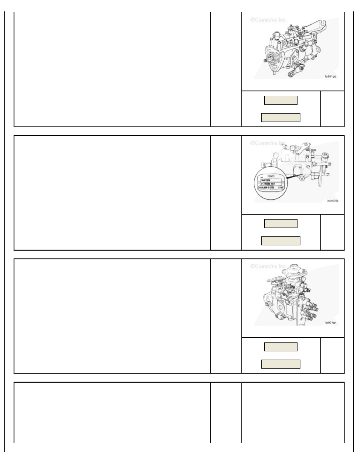
The Lucas CAV DPA distributor-type fuel injection pump
can be found on the following engine applications:
Marine
Industrial.
TOC
SMALL | MEDIUM | LARGE
Next
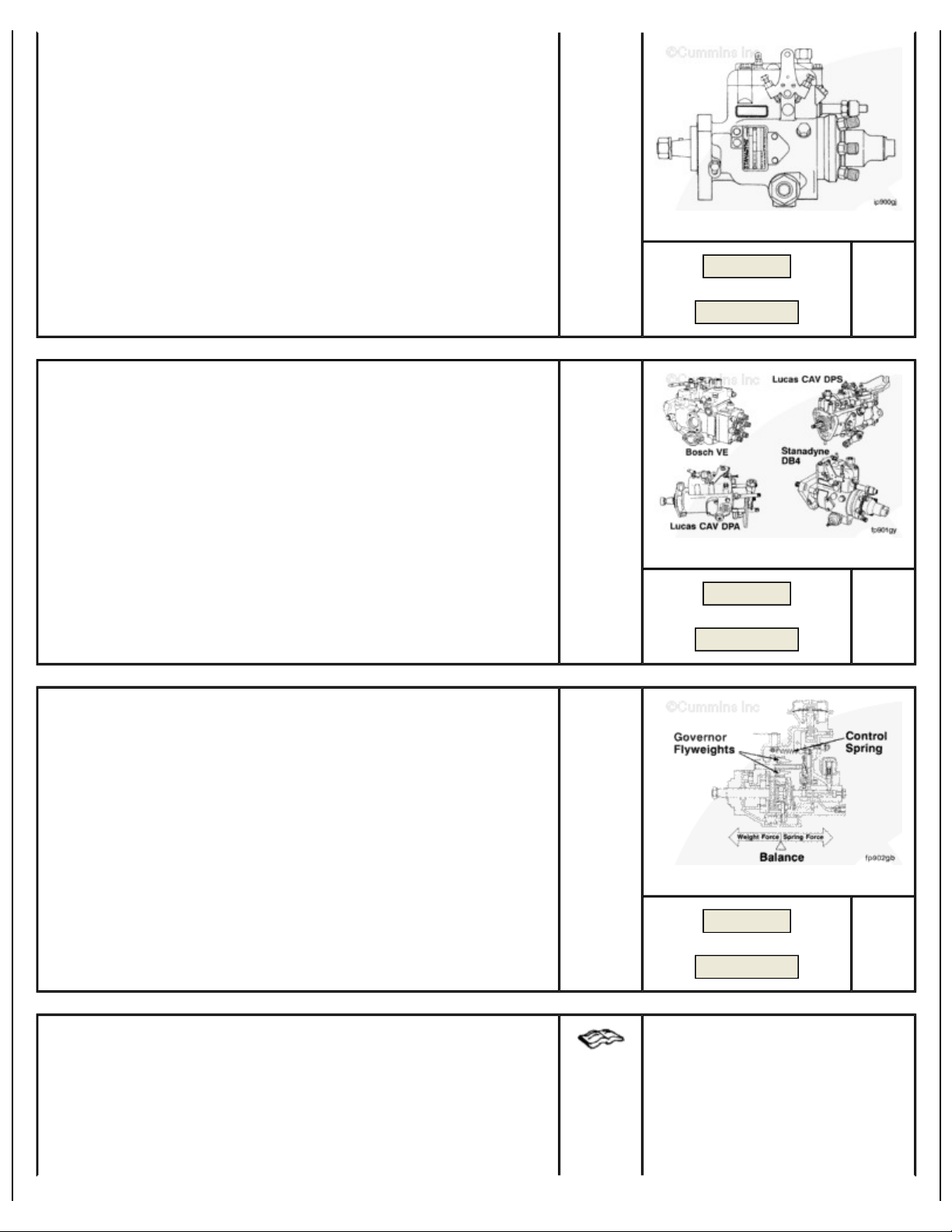
The Lucas CAV DPS distributor-type fuel injection pump
can be found on the following engine application:
European and U.K. automotive ratings.
Page 5
SMALL | MEDIUM | LARGE
Page
5
of 30Fuel Injection Pump, Rotary
10/31/2008
https://quickserve.cummins.com/qs2/pubsys2/xml/en/procedures/40/40
-
005-014-tr.html
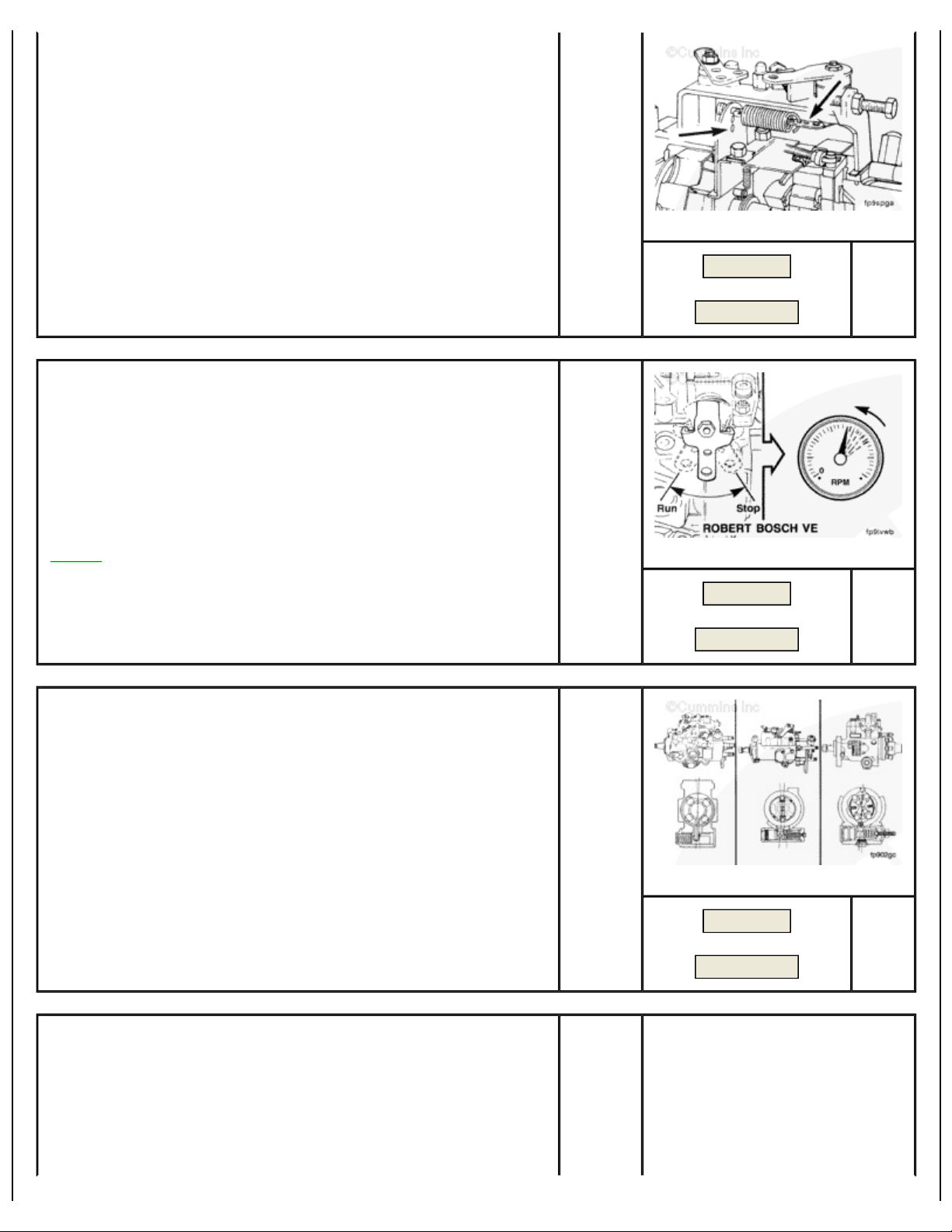
The Delphi DP210 distributor-type fuel injection pump can
be found on the following applications:
Industrial (Tier 2/Stage II Certified).
The Bosch® VE distributor-type fuel injection pump can be
found on the following engine applications:
Previous
Next
SMALL | MEDIUM | LARGE
Previous
Next
Industrial
1991 low-horsepower automotive ratings.
The Stanadyne DB4 distributor-type fuel injection pump can
be found on the following engine application:
Gen Sets
SMALL | MEDIUM | LARGE
Previous
Next
Page 6
SMALL | MEDIUM | LARGE
Page
6
of 30Fuel Injection Pump, Rotary
10/31/2008
https://quickserve.cummins.com/qs2/pubsys2/xml/en/procedures/40/40
-
005-014-tr.html
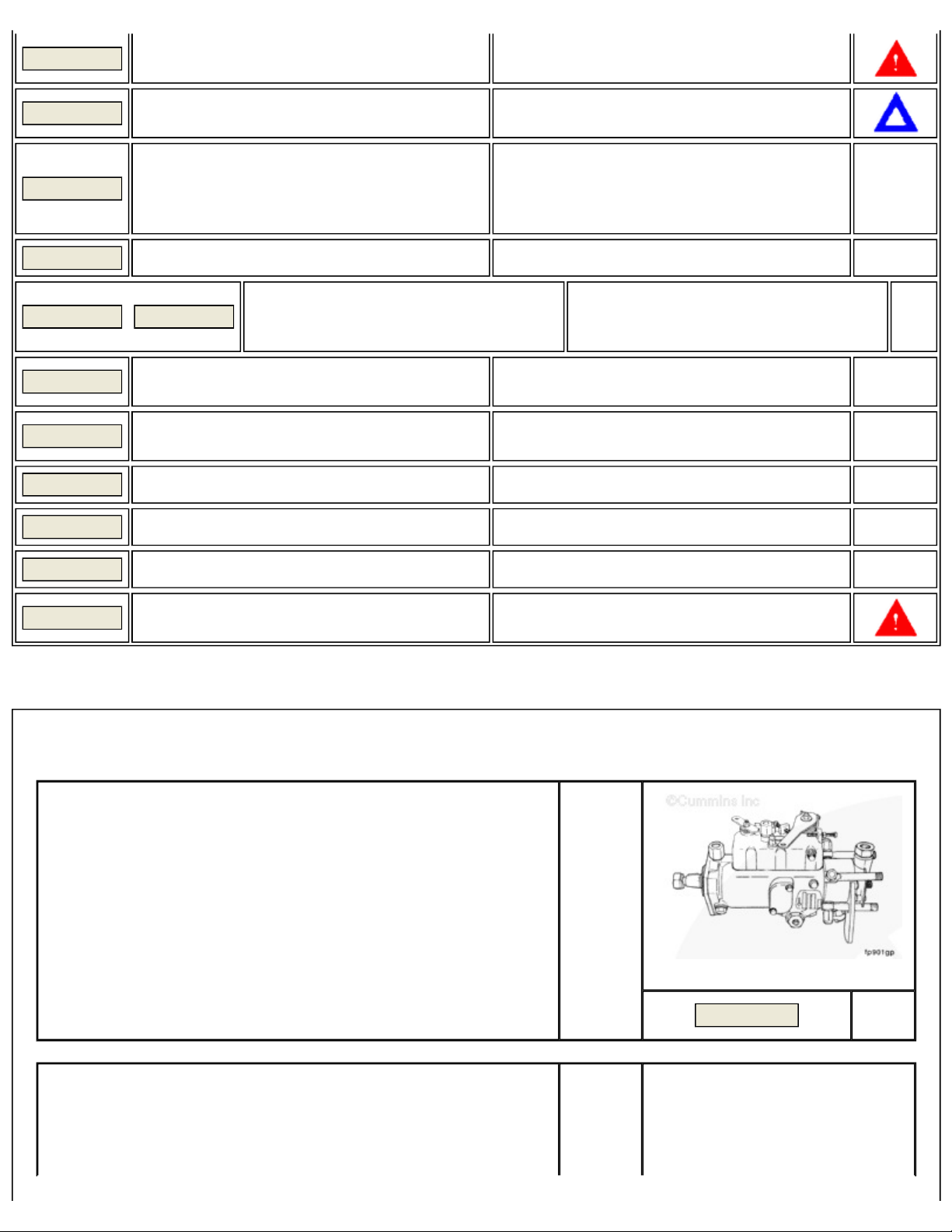
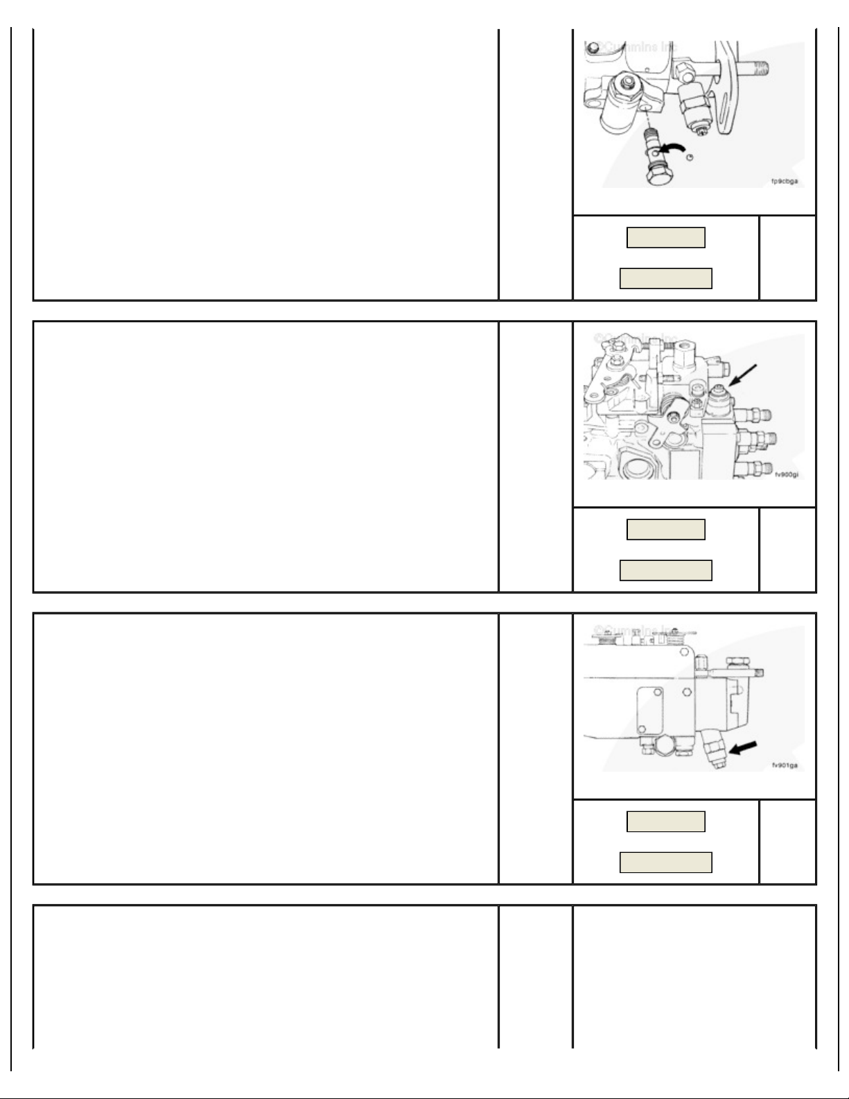
Fuel Injection Pump (Distributor Type)
The fuel injection pumps, Bosch® VE, Lucas CAV DPA,
Stanadyne DB4, Lucas CAV DPS, and Delphi DP210, are
rotary distributor pumps. These pumps perform the four
basic functions of:
1. Producing the high fuel pressure required for injection
2. Metering the exact amount of fuel for each injection
cycle
3. Distributing the high-pressure, metered fuel to each
cylinder at the precise time
4. Varying the timing relative to engine speed.
Distributor-Type Pump Governor
Previous
Next
SMALL | MEDIUM | LARGE
Previous
Next
Balance between the governor flyweights and control lever
position controls the metering of the amount of fuel to be
injected.
The fuel injection pump governor performance and setting
can affect engine power. Special equipment and qualified
personnel are required to verify governor performance. If
the seals are broken on the external Bosch® VE adjustment
screw, the fuel rate can, perhaps, be out of adjustment.
The Lucas CAV DPA/DPS fuel injection pump uses a coded
spring connection to change the governor setting. Incorrect
connection of the governor spring can affect performance.
Adjustments and rating changes are described in the
Master Repair Manual, Injector Pumps and Injectors,
SMALL | MEDIUM | LARGE
Previous
Next
Page 7
Bulletin 3666037.
Page
7
of 30Fuel Injection Pump, Rotary
10/31/2008
https://quickserve.cummins.com/qs2/pubsys2/xml/en/procedures/40/40
-
005-014-tr.html
SMALL | MEDIUM | LARGE
Manual Shutdown Levers
Both fuel injection pumps are equipped with mechanical
shutdown levers. These levers are spring-loaded in the run
position.
all applications will use these manual
Not
shutdown controls and there will be no cable or rod
connected to the lever.
NOTE: Partial actuation of the mechanical shutdown
levers will affect fuel flow and engine power.
Advance Timing Mechanism
Previous
Next
SMALL | MEDIUM | LARGE
Previous
Next
Regulated pressure produced by a vane supply pump in
both fuel injection pumps is used to advance the timing as
the engine speed increases. A return spring is used to
retard the timing as the engine speed is reduced. If a spring
breaks, the timing will go to the advance position, resulting
in torque loss, fuel knock, and possible engine overheating.
Retarded (late) timing will result in torque loss, high fuel
consumption, and white to black smoke.
The Lucas CAV DPA/DPS advance timing mechanism uses
a check ball in the circuit which, if omitted during assembly,
will result in no timing advance. If the fuel injection pump
has been replaced or the mechanism has been removed to
fix a leak, the problem can be that the check ball is missing.
SMALL | MEDIUM | LARGE
Previous
Next
Page 8
SMALL | MEDIUM | LARGE
Page
8
of 30Fuel Injection Pump, Rotary
10/31/2008
https://quickserve.cummins.com/qs2/pubsys2/xml/en/procedures/40/40
-
005-014-tr.html
Electrical Shutoff Valves
The fuel injection pumps are equipped with electrical shutoff
valves. These solenoid-operated valves block the supply of
fuel to the high-pressure pumping and distribution
components.
The Bosch® VE shutoff valve is located at the top rear of
the pump.
The Lucas CAV DPA/DPS shutoff valve is located at the
bottom rear of the pump.
Previous
Next
SMALL | MEDIUM | LARGE
Previous
Next
Both 12- and 24-VDC activate-to-run and activate-to-stop
solenoids are available.
The Stanadyne DB4 shutdown solenoid is located under the
governor cover.
Both 12-VDC and 24-VDC activate-to-run and activate-tostop solenoids are available.
SMALL | MEDIUM | LARGE
Previous
Next
Page 9
SMALL | MEDIUM | LARGE
indexed to the shaft
Page
9
of 30Fuel Injection Pump, Rotary
10/31/2008
https://quickserve.cummins.com/qs2/pubsys2/xml/en/procedures/40/40
-
005-014-tr.html
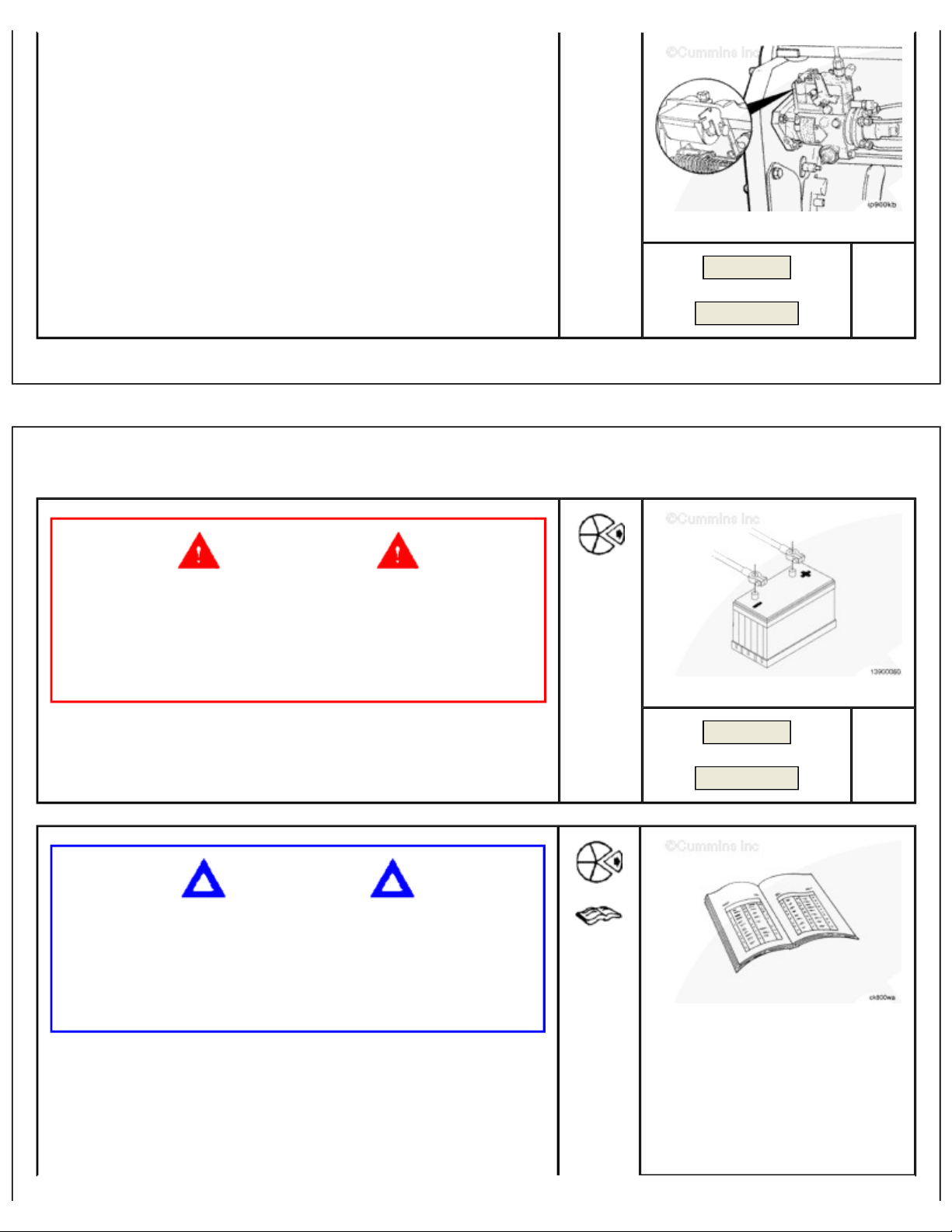
Preparatory Steps
Batteries can emit explosive gases. To reduce the
possibility of personal injury, always ventilate the
compartment before servicing the batteries. To reduce
the possibility of arcing, remove the negative (-) battery
cable first and attach the negative (-) battery cable last.
WARNING
Previous
Next
TOC
SMALL | MEDIUM | LARGE
Disconnect the batteries.
CAUTION
Do not remove the control lever. The fuel control lever on
the Bosch® VE fuel injection pump is
during pump calibration. If the lever has been removed
and reinstalled incorrectly, engine speed and power will
be affected.
Rotary Distributor Type Fuel Injection Pumps
Bosch® VE, Lucas CAV DPA, Stanadyne DB4, and Delphi
DP210
Previous
Next
SMALL | MEDIUM | LARGE
Page 10

Page
10
of 30Fuel Injection Pump, Rotary
10/31/2008
https://quickserve.cummins.com/qs2/pubsys2/xml/en/procedures/40/40
-
005-014-tr.html
Disconnect the fuel drain manifold. Refer to
Previous
Summary 1
Procedure 006-021.
Remove the injection pump supply line. Refer to
Next
Procedure 006-024.
Remove the high-pressure lines. Refer to Procedure
006-051.
Disconnect the electrical wire to the fuel shutoff valve.
Refer to Procedure 005-043.
Remove the fuel air control tube, if used. Refer to
Procedure 006-001.
Disconnect all control linkage. Refer to the OEM
service manual
Remove the pump support bracket. Refer to
Procedure 005-033.
Remove
Front Gear Train
Remove the access cap, gear retaining nut, and washer.
TOC
SMALL | MEDIUM | LARGE
Previous
Next
Summary 2
NOTE: Be sure to disengage the pin after locating top
dead center.
Locate top dead center for cylinder Number 1 by barring the
engine slowly, while pushing in on the top dead center pin.
SMALL | MEDIUM | LARGE
Page 11

Previous
Page
11
of 30Fuel Injection Pump, Rotary
10/31/2008
https://quickserve.cummins.com/qs2/pubsys2/xml/en/procedures/40/40
-
005-014-tr.html
Lucas CAV DPA Pump and Delphi DP210
Loosen the CAV fuel injection pump lock screw and position
the special washer; then tighten the lock screw against the
pump drive shaft.
Torque
Value:
7
n.m
[62 inlb ]
Next
Summary 3
Summary 4
SMALL | MEDIUM | LARGE
Previous
Next
Summary 5
Stanadyne DB4 Pump
Loosen the Stanadyne DB4 fuel injection pump lock screw
and position the special washer. Tighten the lock screw
until contact is made with the fuel injection pump drive
shaft.
Torque
Value:
12
n.m
[106 inlb ]
Summary 6
SMALL | MEDIUM | LARGE
Previous
Next
Summary 7
Summary 8
Bosch® VE
The special washer on the Bosch® VE injection pump
must
be removed so the lock screw can be tightened against the
Page 12

drive shaft.
Page
12
of 30Fuel Injection Pump, Rotary
10/31/2008
https://quickserve.cummins.com/qs2/pubsys2/xml/en/procedures/40/40
-
005-014-tr.html
Torque
Value:
30
n.m
[22 ftlb ]
NOTE: Wire the washer to the pump.
SMALL | MEDIUM | LARGE
Pull the fuel injection pump drive gear loose from the pump
drive shaft.
Use fuel pump gear puller, Part Number 3163381 or Part
Number 3824469, with M8-1.25 x 50 capscrews, Grade
8.8 or equivalent.
Previous
Next
Summary 9
SMALL | MEDIUM | LARGE
Previous
Next
Summary 10
CAUTION
Do not drop drive gear key when removing the pump.
Failure to do so can result in severe engine damage.
Remove the three mounting nuts and take off the fuel
injection pump.
NOTE: Fuel pumps on engines designed to meet Tier
2/Stage II Industrial emissions levels have straight
holes ( not kidney slots) and do not use a timing key.
SMALL | MEDIUM | LARGE
Previous
Next
Summary 11
Page 13

Remove the gasket and clean the surface.
Page
13
of 30Fuel Injection Pump, Rotary
10/31/2008
https://quickserve.cummins.com/qs2/pubsys2/xml/en/procedures/40/40
-
005-014-tr.html
SMALL | MEDIUM | LARGE
Rear Gear Train
Permanently mark the injection pump flange to match the
mark on the fuel pump mounting plate.
Previous
Next
Summary 12
SMALL | MEDIUM | LARGE
Previous
Unlike the front gear train engine, do
remove the
NOT
timing pin until completion of the repair. Failure to do so
can result in difficult reassembly and incorrect timing of the
fuel pump.
Next
Summary 13
SMALL | MEDIUM | LARGE
Previous
Next
Summary 14
Page 14

CAUTION
Page
14
of 30Fuel Injection Pump, Rotary
10/31/2008
https://quickserve.cummins.com/qs2/pubsys2/xml/en/procedures/40/40
-
005-014-tr.html
Failure to properly torque the lock screw will result in
improper timing of the pump during reassembly.
Bosch® VE
The special washer on the Bosch® VE injection pump
be removed so the lock screw can be tightened
must
against the drive shaft.
SMALL | MEDIUM | LARGE
Torque
Value:
40
n.m
[22 ftlb ]
NOTE: Wire the washer to the pump.
NOTE: The torque specification for the rear gear train
engine is higher than the front gear train engine, to
prevent rotation of the pump shaft during installation
of the fuel pump gear retaining nut.
Remove the mounting nuts and bolts affixing the fuel pump
mounting plate to the rear gear housing.
Take off the fuel injection pump, fuel pump mounting plate,
and fuel pump gear as an assembly.
NOTE: Make sure the gear does not rotate during
removal; failure to do so can result in incorrect timing
of the pump during installation.
Previous
Next
Summary 15
SMALL | MEDIUM | LARGE
Remove the gasket and clean the surface.
Previous
Next
Summary 16
Summary 17
Page 15

SMALL | MEDIUM | LARGE
Page
15
of 30Fuel Injection Pump, Rotary
10/31/2008
https://quickserve.cummins.com/qs2/pubsys2/xml/en/procedures/40/40
-
005-014-tr.html
Mark a tooth on the fuel gear pump relative to the fuel
pump mounting plate.
Previous
Next
Summary 18
SMALL | MEDIUM | LARGE
Previous
Next
Summary 19
Remove the fuel pump retaining nut and washer.
Remove the fuel pump gear.
Loosen the three mounting nuts attaching the fuel pump to
the fuel pump mounting plate.
Remove the fuel pump from the fuel pump mounting plate.
SMALL | MEDIUM | LARGE
Previous
Next
Summary 20
Summary 21
Remove the gasket material and clean the surface.
Page 16

SMALL | MEDIUM | LARGE
Page
16
of 30Fuel Injection Pump, Rotary
10/31/2008
https://quickserve.cummins.com/qs2/pubsys2/xml/en/procedures/40/40
-
005-014-tr.html
Install
Front Gear Train
Verify cylinder Number 1 is at top dead center by barring
the engine slowly while pushing in on the top dead center
pin.
Previous
Next
Summary 22
TOC
Install a new gasket.
SMALL | MEDIUM | LARGE
Previous
Next
Summary 23
Page 17

SMALL | MEDIUM | LARGE
Page
17
of 30Fuel Injection Pump, Rotary
10/31/2008
https://quickserve.cummins.com/qs2/pubsys2/xml/en/procedures/40/40
-
005-014-tr.html
CAUTION
The drive shaft must be clean and free of all oil before
installation. Failure to make certain the drive shaft is free
of oil can result in the drive gear slipping on the shaft.
NOTE: The shaft of a new or reconditioned pump is
locked so the key aligns with the drive gear keyway
when cylinder Number 1 is at top dead center on the
compression stroke.
Install the pump. Make sure the key does
gear housing.
fall into the
not
Previous
Next
Summary 24
SMALL | MEDIUM | LARGE
Previous
NOTE: Fuel pumps on engines designed to meet Tier
2/Stage II Industrial emission levels do not use a timing
key.
Hand tighten the three mounting nuts. The pump
must
be
free to move in the slots.
NOTE: Fuel pumps on engines designed to meet Tier
2/Stage II Industrial emissions levels have straight
holes ( not kidney slots) and do not use a timing key.
Next
SMALL | MEDIUM | LARGE
Previous
Next
Summary 25
CAUTION
Page 18

Page
18
of 30Fuel Injection Pump, Rotary
10/31/2008
https://quickserve.cummins.com/qs2/pubsys2/xml/en/procedures/40/40
-
005-014-tr.html
Be sure the timing pin is disengaged before the final
torque step to avoid damage to the timing pin.
Install the pump drive shaft nut and spring washer. The
pump will rotate slightly because of gear helix and
clearance. This is acceptable, provided the pump is free to
move on the flange slots and the crankshaft does
not
move.
SMALL | MEDIUM | LARGE
Previous
Torque
Value:
15 to 20
n.m
[132 to 177
in-lb ]
If installing the original pump, rotate the pump to align the
scribe marks.
Torque
Value:
24
n.m
[18 ftlb ]
Next
Summary 26
SMALL | MEDIUM | LARGE
Previous
Next
Summary 27
If installing a new or rebuilt pump without scribe marks,
take up gear lash by rotating the pump against the
direction of drive rotation. Tighten the flange mounting
nuts.
Torque
Value:
24
n.m
[18 ftlb ]
SMALL | MEDIUM | LARGE
Previous
Next
Summary 28
Page 19

Permanently mark the injection pump flange to match the
Page
19
of 30Fuel Injection Pump, Rotary
10/31/2008
https://quickserve.cummins.com/qs2/pubsys2/xml/en/procedures/40/40
-
005-014-tr.html
mark on the gear housing.
SMALL | MEDIUM | LARGE
Lucas CAV DPA Pump and Delphi DP210
For CAV fuel injection pumps, loosen the lockscrew and
position the special washer behind the lockscrew head.
Torque
Value:
20
n.m
[177 inlb ]
Previous
Next
Summary 29
SMALL | MEDIUM | LARGE
Previous
Next
Summary 30
Stanadyne DB4 Pump
For Stanadyne DB4 fuel injection pumps, loosen the lock
screw and position the special washer behind the lock
screw head.
Tighten the lock screw.
SMALL | MEDIUM | LARGE
Previous
Next
Summary 31
Page 20

Bosch® VE
Page
20
of 30Fuel Injection Pump, Rotary
10/31/2008
https://quickserve.cummins.com/qs2/pubsys2/xml/en/procedures/40/40
-
005-014-tr.html
Loosen the Bosch® fuel pump lock timing screw and install
the special washer that is wired to the fuel pump.
Tighten the Bosch® fuel pump lock timing screw.
Torque
Value:
13
n.m
[115 inlb ]
Disengage the timing pin before rotating the crankshaft.
SMALL | MEDIUM | LARGE
Previous
Next
Summary 32
Tighten the pump retaining nut.
Bosch® VE (M14-1.5 nut) 98 n.m [72 ft-lb ]
Bosch® VE (M12 nut) 65 n.m [48 ft-lb ]
Lucas CAV/DPA 81 n.m [60 ft-lb ]
Stanadyne 65 n.m [48 ft-lb ]
Delphi DP21 93 n.m [68 ft-lb ]
SMALL | MEDIUM | LARGE
Previous
Next
Summary 33
Summary 36
SMALL | MEDIUM | LARGE
Previous
Next
Summary 37
Page 21

Page
21
of 30Fuel Injection Pump, Rotary
10/31/2008
https://quickserve.cummins.com/qs2/pubsys2/xml/en/procedures/40/40
-
005-014-tr.html
Install the access cap.
SMALL | MEDIUM | LARGE
Rear Gear Train
Verify cylinder number 1 is at top dead center by barring
the engine slowly while pushing in on the top dead center
pin.
Previous
Next
Summary 38
SMALL | MEDIUM | LARGE
Previous
Install a new fuel pump gasket on the fuel pump mounting
plate.
Next
Summary 39
SMALL | MEDIUM | LARGE
Previous
Next
Summary 40
Page 22

the drive shaft is free
Page
22
of 30Fuel Injection Pump, Rotary
10/31/2008
https://quickserve.cummins.com/qs2/pubsys2/xml/en/procedures/40/40
-
005-014-tr.html
Install the fuel pump to the fuel pump mounting plate.
Torque
Value:
18
n.m
[159 inlb ]
SMALL | MEDIUM | LARGE
If installing the original fuel pump, rotate the pump to align
the scribe marks on the fuel pump mounting plate.
Torque
Value:
18
n.m
[159 inlb ]
Previous
Next
Summary 41
SMALL | MEDIUM | LARGE
Previous
Next
Summary 42
CAUTION
The drive shaft must be clean and free from oil before
installation. Failure to make certain
of oil can result in the drive gear slipping on the shaft.
Install the fuel pump gear on the fuel pump shaft.
Align the mark on the fuel pump gear with the mark on the
fuel pump mounting plate.
Install the fuel pump drive shaft nut and spring washer.
Tighten the pump retaining nut.
SMALL | MEDIUM | LARGE
Previous
Next
Summary 43
Summary 44
Page 23

Torque
Page
23
of 30Fuel Injection Pump, Rotary
10/31/2008
https://quickserve.cummins.com/qs2/pubsys2/xml/en/procedures/40/40
-
005-014-tr.html
Value:
98
n.m
[72 ftlb ]
With a new fuel pump cover plate gasket, install the fuel
pump, fuel pump mounting plate, and fuel pump gear
assembly onto the rear gear housing.
M8 18 n.m [159 in-lb ]
M10 30 n.m [266 in-lb ]
Loosen the Bosch® fuel pump lock timing screw and install
the special washer that is wired to the pump.
Tighten the Bosch® fuel pump lock timing screw.
Torque
Value:
13
n.m
[115 inlb ]
SMALL | MEDIUM | LARGE
Previous
Next
Summary 45
SMALL | MEDIUM | LARGE
Disengage the timing pin before rotating the crankshaft.
Previous
Next
Previous
SMALL | MEDIUM | LARGE
Summary 46
Summary 47
Page 24

Next
Page
24
of 30Fuel Injection Pump, Rotary
10/31/2008
https://quickserve.cummins.com/qs2/pubsys2/xml/en/procedures/40/40
-
005-014-tr.html
Time
Tier 2/Stage II Timing Adjustment
If the pump timing is out by more than the specified
tolerance as determined in Procedure 005-037 it is
possible on Tier 2/Stage II engines, which no longer use
the keyway in the fuel pump shaft, that the fuel pump gear
has slipped on the fuel pump shaft. The fuel pump gear to
pump shaft taper will need to be broken so the pump timing
can be reset.
NOTE: This procedure applies to front gear train Tier
2/Stage II engines only. Refer to Procedure directions
in 005-037, when adjusting the fuel pump timing of
engines equipped with kidney slots.
The top dead center timing pin
the engine in the
clockwise
direction, when viewed from
the front of the engine, until the dial indicator reading
reflects the plunger travel specified on the engine
dataplate. This point will be beyond top dead center. Lock
the pump drive shaft at this position. Refer to Procedure
100-001 Engine Identification in Section E, for the engine
dataplate location.
NOTE: If barring the engine past the specified timing
plunger travel value, turn the engine in an
counterclockwise direction, when viewed from the
front of the engine, past top dead center at least one
quarter turn, then bring the engine back toward top
dead center in a clockwise direction when viewed from
the front of the engine, until the desired timing value is
achieved.
The special washer on the Bosch® VE injection pump
be removed so the lock screw can be tightened
must
against the drive shaft.
Torque
Value:
30
n.m
be disengaged. Bar
must
[22 ftlb ]
TOC
SMALL | MEDIUM | LARGE
Previous
Next
Summary 48
SMALL | MEDIUM | LARGE
Previous
Next
Summary 49
Page 25

NOTE: Wire the washer to the fuel pump.
recommendations for
Page
25
of 30Fuel Injection Pump, Rotary
10/31/2008
https://quickserve.cummins.com/qs2/pubsys2/xml/en/procedures/40/40
-
005-014-tr.html
Remove the access cap.
Remove the fuel pump gear retaining nut and washer.
SMALL | MEDIUM | LARGE
To remove the fuel pump gear, use gear puller, Part
Number ST647 or 3163381, to separate the fuel pump
gear from the shaft.
With the gear loose from the fuel pump drive shaft, bar the
engine in the opposite direction of rotation, when viewed
from the front of the engine, past top dead center at least
one quarter turn. Then bar engine in the direction of
rotation to top dead center until the timing pin engages the
camshaft.
Previous
Next
Summary 50
SMALL | MEDIUM | LARGE
Previous
Next
Summary 51
WARNING
When using solvents, acids, or alkaline materials for
cleaning, follow the manufacturer's
use. Wear goggles and protective clothing to reduce the
possibility of personal injury.
WARNING
Wear appropriate eye and face protection when using
compressed air. Flying debris and dirt can cause
SMALL | MEDIUM | LARGE
Page 26

personal injury.
Page
26
of 30Fuel Injection Pump, Rotary
10/31/2008
https://quickserve.cummins.com/qs2/pubsys2/xml/en/procedures/40/40
-
005-014-tr.html
Previous
Clean the fuel injection pump drive shaft taper and drive
gear bore with a residue-free cleaner. Dry both surfaces
with compressed air.
Failure to clean and dry the shaft thoroughly can result in
further timing slip after the engine is run.
CAUTION
Prior to torquing the fuel pump gear nut, make sure the
engine is locked and can not rotate during final torquing
of the fuel pump nut.
This can be achieved by using the engine barring tool to
prevent the engine from rotating. Make sure the fuel pump
is locked at this stage.
Next
Summary 52
SMALL | MEDIUM | LARGE
Previous
Next
Summary 53
Push the fuel pump gear onto the shaft and assemble the
washer and nut.
Remove the top dead center timing pin from the camshaft
and the timing pin on the damper, if used.
Tighten the fuel pump retaining nut.
Bosch® VE (M14-1.5 nut) 98 n.m [72 ft-lb ]
Bosch® VE (M12 nut) 65 n.m [48 ft-lb ]
Lucas CAV/DPA 81 n.m [60 ft-lb ]
Stanadyne 65 n.m [48 ft-lb ]
Delphi DP21 93 n.m [68 ft-lb ]
SMALL | MEDIUM | LARGE
Previous
Next
Summary 54
Summary 55
Bosch® VE
Loosen the Bosch® fuel pump lock timing screw and install
the special washer that is wired to the fuel pump.
Page 27

Tighten the Bosch® fuel pump lock timing screw.
Page
27
of 30Fuel Injection Pump, Rotary
10/31/2008
https://quickserve.cummins.com/qs2/pubsys2/xml/en/procedures/40/40
-
005-014-tr.html
Torque
Value:
13
n.m
[115 inlb ]
SMALL | MEDIUM | LARGE
CAUTION
To reduce the possibility of engine or timing pin damage,
you must disengage the timing pin before attempting to
bar or crank the engine.
Disengage the timing pin before rotating the crankshaft.
Install the access cap and check to make sure the engine
barring tool is removed, then recheck the timing as
described in the previous steps.
Previous
Next
SMALL | MEDIUM | LARGE
Previous
Next
Summary 56
If the timing is within tolerance, remove the timing gauge
from the fuel pump and replace the plug.
Torque
Value:
10
n.m
[89 inlb ]
Tighten the gear pump retaining nut.
Bosch® VE (M14-1.5 nut) 98 n.m [72 ft-lb ]
SMALL | MEDIUM | LARGE
Previous
Next
Summary 57
Summary 58
Page 28

Bosch® VE (M12 nut) 65 n.m [48 ft-lb ]
Page
28
of 30Fuel Injection Pump, Rotary
10/31/2008
https://quickserve.cummins.com/qs2/pubsys2/xml/en/procedures/40/40
-
005-014-tr.html
Lucas CAV/DPA 81 n.m [60 ft-lb ]
Stanadyne 65 n.m [48 ft-lb ]
Delphi DP21 93 n.m [68 ft-lb ]
SMALL | MEDIUM | LARGE
Install the access cap.
Previous
Next
Summary 34
Summary 59
SMALL | MEDIUM | LARGE
Previous
Finishing Steps
Rotary Distributor Type Fuel Injection Pumps
Bosch® VE, Lucas CAV DPA, Stanadyne DB4, and Delphi
DP210
Install the injection pump support bracket. Refer to
Procedure 005-033
Next
Summary 35
Summary 60
TOC
Page 29

Feedback / Help
Page
29
of 30Fuel Injection Pump, Rotary
10/31/2008
https://quickserve.cummins.com/qs2/pubsys2/xml/en/procedures/40/40
-
005-014-tr.html
Install all high-pressure fuel lines. Refer to Procedure
006-051
Install the injection pump supply line. Refer to
Procedure 006-024
Connect the fuel drain manifold. Refer to Procedure
006-021
Connect the electrical wire to the fuel shutoff valve.
Refer to Procedure 005-043
If required, install the air-to-fuel control valve. Refer
to Procedure 006-001
Disconnect all control linkage. Refer to OEM service
manual.
NOTE: When connecting the cable and rod to the
control lever, adjust the length so the lever has stopto-stop movement. Adjust the length of the cable or
rod to the mechanical shutdown lever so there is stopto-stop movement.
Replacing the fuel supply lines, fuel filters, fuel injection
pump, high-pressure fuel lines, and injectors will let air
enter the fuel system. Follow the specified procedure to
bleed the air from the system.
SMALL | MEDIUM | LARGE
Previous
Next
Summary 61
Refer to Procedure 006-015, Fuel Filter, Spin-On, for
proper venting of the low pressure side of the fuel
system
Refer to Procedure 006-051, Injector Supply Lines
(High Pressure), for venting of the high-pressure side
of the fuel system.
WARNING
Batteries can emit explosive gases. To reduce the
possibility of personal injury, always ventilate the
compartment before servicing the batteries. To reduce
the possibility of arcing, remove the negative (-) battery
cable first and attach the negative (-) battery cable last.
Connect the batteries
Operate the engine and check for leaks.
SMALL | MEDIUM | LARGE
Previous
Summary 62
Last Modified: 05-Dec-2006
Page 30

Copyright © 2006 Cummins Inc. All rights reserved
Page
30
of 30Fuel Injection Pump, Rotary
10/31/2008
https://quickserve.cummins.com/qs2/pubsys2/xml/en/procedures/40/40
-
005-014-tr.html
 Loading...