

CUMMINS PowerCommand 3100 Series, DQAD, DQAF, DQAE Installation Manual

Power
Generation
Installation Manual
PowerCommand® Control
3100
Series
Generator
Sets
Printed in U.S.A.
DQAD.
Models
DQAE. DQAF
960-0624 5-2001

Table of Contents
SECTION
2
3
TITLE
IMPORTANT SAFETY INSTRUCTIONS iii
INTRODUCTION
SPECIFICATIONS
MOUNTING
MECHANICAL
DC
PAGE
About this Manual 1-1
Installation Overview 1-2
2-1
THE
GENERATOR
General 3-1
Location 3-1
Mounting 3-2
Access to Set 3-2
Vibration Isolators 3-4
CONNECTIONS
General 4-1
Fuel System 4-1
Exhaust System 4-4
Ventilation and Cooling 4-6
CONTROL
Control Wiring .* 5-1
TB1 Remote Monitor/Control Connections 5-1
Run Relays (K11,K12, Kl
Alarm Relay (K14) 5-4
WIRING
SET
3)
5-3
California
Proposition 65
Diesel engine exhaust
to the State of California to cause cancer, birth defects, and
other reproductive harm.
and
some of its constituents are known
Warning
6 AC
7
PRESTART
8
INSTALLATION
ELECTRICAL
General 6-1
Transfer Switch 6-2
AC Wiring 6-3
Control Heater (Optional) 6-5
Coolant Heater 6-6
Generator Heater 6-7
Fuel Transfer Pump 6-8
Ground Fault Alarm Relay (Optional) 6-9
PREPARATION
General 7-1
PCC Power On/Standby Mode 7-1
Electrical System 7-2
PCC Options Prestart Checks 7-3
Starting 7-5
General ..8-1
Generator Set Support 8-1
Cooling Air Flow 8-1
Diesel Fuel System 8-1
Exhaust System 8-2
AC and DC Wiring 8-2
Genset Prestart 8-2
CONNECTIONS
CHECKLIST
9
WIRING
General .• 9-1
DIAGRAMS

IMPORTANT
SAFETY
INSTRUCTIONS
SAVE THESE INSTRUCTIONS important instructions that should be followed during
installation and maintenance of the generator
ies.
Before operating the generator set (genset), read the
Operator's Manual and become familiar with it and the
equipment. Safe and efficient operation can be
achieved only if the equipment is properly operated
and maintained. Many accidents are caused by failure
to follow fundamental rules and precautions.
The following symbols, found throughout this manual,
alert you to potentially dangerous conditions to the operator, service personnel, or the equipment.
ri^ij'isMazd This symbol warns of immediate
hazards which will result in severe personal in-
jury or death.
IAWARNINGI This symbol refers to a hazard or un-
safe practice which can result in severe personal injury or death.
IACAUTIONI This symbol refers to a hazard or un-
safe practice which can result in personal injury
or product or property damage.
This
manual contains
and
batter-
FUEL AND FUMES ARE FLAMMABLE
Fire,
explosion, and personal injury or death can result
from improper practices.
• DO NOT fill fuel tanks while engine is running, unless tanks are outside the engine compartment.
Fuel contact
fire hazard.
• DO NOT permit any flame, cigarette, pilot light,
spark, arcing equipment, or other ignition source
near the generator set or fuel tank.
• Fuel lines must be adequately secured and free of
leaks.
made with an approved flexible
coated or copper fuel lines with diesel
• Be sure all fuel supplies have a positive shutoff
valve.
• Be sure battery area has been well-ventilated prior
to sen/icing near
explosive hydrogen gas that can be ignited by arcing,
sparking, smoking, etc.
with
hot engine or exhaust is a potential
Fuel connection at the engine should be
line.
Do not
it.
Lead-acid batteries emit a highly
fuel.
use
zinc
EXHAUST
• Provide an adequate exhaust system to properly
expel discharged gases away from enclosed or
sheltered areas and areas where individuals are
likely to congregate. Visually and audibly inspect
the exhaust daily for leaks per the maintenance
schedule. Make sure that exhaust manifolds are secured and not
heat a compartment.
• Be sure the unit is well ventilated.
• Engine exhaust and some of its constituents are
known to the state of California to cause cancer,
birth defects, and other reproductive harm.
GASES
warped.
ARE
DEADLY
Do not use exhaust gases to
MOVING PARTS CAN CAUSE SEVERE
PERSONAL INJURY OR DEATH
• Keep your hands, clothing, and jewelry away from
moving parts.
• Before starting work on the generator set, disconnect battery charger from its AC source, then dis-
connect starting batteries, negative (-) cable first.
This will prevent accidental starting.
• Make sure that fasteners on the generator set are
secure. Tighten supports and clamps, keep guards
in position over
• Do not wear loose clothing or jewelry
moving parts, or while working on electrical equipment. Loose clothing and jewelry can become
caught in moving parts.
• If adjustment must be made while the unit is
ning,
use extreme caution around hot manifolds,
moving parts, etc.
fans,
drive belts, etc.
in
the vidnity of
run-
DO NOT OPERATE IN FLAMMABLE AND
EXPLOSIVE ENVIRONMENTS
Flammable vapor
become difficult to stop, resulting in possible fire, explosion,
severe personal injury and
genset where a flammable vapor environment can be
created by fuel
equipped with an automatic safety device to block the air
intake and stop the
the genset are solely responsible for operating the
set safely. Contact your authorized Onan/Cummins
er or distributor for more information.
can
cause an engine to overspeed and
death.
spill,
leak, etc., unless the genset is
engine.
The owners and operators of
Do not operate a
gen-
deal-
in
LS-13L
ELECTRICAL
SEVERE
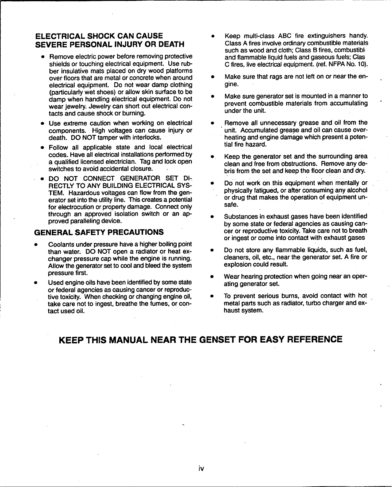
• Remove electric power before removing protective
shields or touching electrical equipment. Use rubber insulative mats placed on dry wood platforms
over floors that are metal or concrete when around
electrical equipment. Do not wear damp clothing
(particularly wet shoes) or allow skin surface to be
damp when handling electrical equipment. Do not
wear jewelry. Jewelry can short out electrical
tacts and cause shock or burning.
• Use extreme caution when working on electrical
components. High voltages can cause injury or
death.
• Follow all applicable state and local electrical
codes. Have all electrical installations performed by
a qualified licensed electrician. Tag and lock open
switches to avoid accidental closure.
• DO NOT CONNECT GENERATOR SET DIRECTLY TO ANY BUILDING ELECTRICAL SYS-
TEM.
Hazardous voltages can flow from the
erator set into the utility
for electrocution or property
through an approved isolation switch or an approved paralleling device.
GENERAL
• Coolants under pressure have a higher boiling point
than
water.
changer pressure cap while the engine is running.
Allow the generator
pressure first.
• Used engine oils have been identified by some state
or federal agencies as causing cancer or reproduc-
tive toxicity. When checking or changing engine oil,
take care not to ingest, breathe the fumes, or
tact used oil.
SHOCK
PERSONAL
DO NOT tamper with interlocks.
SAFETY
DO NOT open a radiator or heat ex-
CAN
INJURY
line.
CAUSE
OR
DEATH
This creates a potential
damage.
Connect only
PRECAUTIONS
set
to cool and bleed the system
con-
gen-
con-
Keep multi-class ABC fire extinguishers handy.
Class A fires involve ordinary combustible materials
such as wood and
and flammable liquid fuels and gaseous
C
fires,
live electrical equipment, (ref. NFPA
Make sure that rags are not left on or near the engine.
Make sure generator set is mounted in a manner to
prevent combustible materials from accumulating
under the unit.
Remove all unnecessary grease and oil from the
* unit. Accumulated grease and oil can cause
heating and engine damage which present a poten-
tial fire hazard.
Keep the generator set and the surrounding area
clean and free from obstructions. Remove any debris from the set and keep the floor clean and dry.
Do not work on this equipment when mentally or
physically
or drug that makes the operation of equipment unsafe.
Substances in exhaust gases have been identified
by some state or federal agencies as causing
cer or reproductive toxicity. Take care not to breath
or ingest or come into contact with exhaust gases
Do not store any flammable liquids, such as
cleaners, oil, etc., near the generator set. A fire or
explosion could result.
Wear hearing protection when going near an
ating generator set.
To prevent serious burns, avoid contact with hot
metal parts such as radiator, turbo charger and exhaust system.
fatigued,
cloth;
Class B
or after consuming any alcohol
fires,
combustibli
fuels;
Clas
No.
10).
over-
can-
fuel,
oper-
KEEP
THIS
MANUAL
NEAR
THE
IV
GENSET
FOR
EASY
REFERENCE
1.
Introduction
ABOUT
This manual covers models produced under the
Cummins®/Onan® and Cummins Power Genera-
tion brand names.
This manual provides installation instructions for
the generator set models listed on the front cover.
This includes the following information:
Mounting Recommendations - for fastening
generator set to base and space requirements
for normal operation and service.
Mechanical Connections and Electrical
connections - covers most aspects of
erator set installation.
THIS
MANUAL
the
gen-
Prestart - Checklist of items or procedures
needed to prepare generator set for operation.
Initial Startup - Test complete system to ensure proper installation, satisfactory performance,
and safe operation. Refer to Operators
Manual for troubleshooting information.
This manual DOES NOT provide application infor-
mation for selecting a generator set or designing the
complete installation. If it is necessary to design the
various integrated systems (fuel, exhaust, cooling,
etc.),
additional information is required. Review
standard installation practices. For engineering
data specific to the generator
ator set Specifications
cation information, refer to Application Manual
T-030, "Liquid Cooled Generator Sets".
and
set,
refer
to
the gener-
Data sheets. For appli-
1-1
INSTALLATION
These installation recommendations apply to
OVERVIEW
typical installations with standard model generator
sets.
Whenever possible, these recommendations
also cover factory designed options or modifica-
tions.
However, because of the many variables in
any installation, it is not possible to provide specific
recommendations for every situation. If there are
any questions not answered by this manual, contact
your nearest Cummins Power Generation distributor for assistance.
Application and Installation
A standby power system must be carefully planned
and correctly installed for proper
operation.
This involves two essential elements: application and installation.
Application (as it applies to generator set installations) refers to the design of the complete standby
power system that usually includes power distribu-
tion equipment, transfer
switches,
ventilation equip-
ment, mounting pads, and cooling, exhaust, and
fuel systems. Each component must be correctly
designed so the complete system will function as intended.
Application and design is an engineering
function generally done by specifying engineers or
other trained specialists. Specifying engineers are
responsible for the design of the complete standby
system and for selecting the materials and products
required.
Installation refers to the actual set-up and assembly of the standby power
system.
The installers set
up and connect the various components of the system as specified in the system design plan. The
complexity of
the
standby system normally requires
the special skills of qualified electricians, plumbers,
sheetmetal workers, etc. to complete the various
segments of the installation. This is necessary so
all components are assembled using standard
methods and practices.
Safety
Considerations
The generator set has been carefully designed to
provide safe and efficient service when properly installed,
maintained, and operated. However, the
overall safety and reliability of the complete system
is dependent on many factors outside the control of
the generator set manufacturer. To avoid possible
safety hazards, make all mechanical and electrical
connections to the generator set exactly as specified in this
manual.
All systems external to the
generator (fuel, exhaust, electrical, etc.) must comply
with all applicable codes. Make certain all required
inspections
code requirements have been satisfied before
and
tests have been completed and all
certifying the installation is complete and ready for service.
Copyright®
Cummins, Onan and PowerCommand are registered trademarks of Cummins Inc.
2001
Cummins Power
Generation.
All rights reserved.
1-2
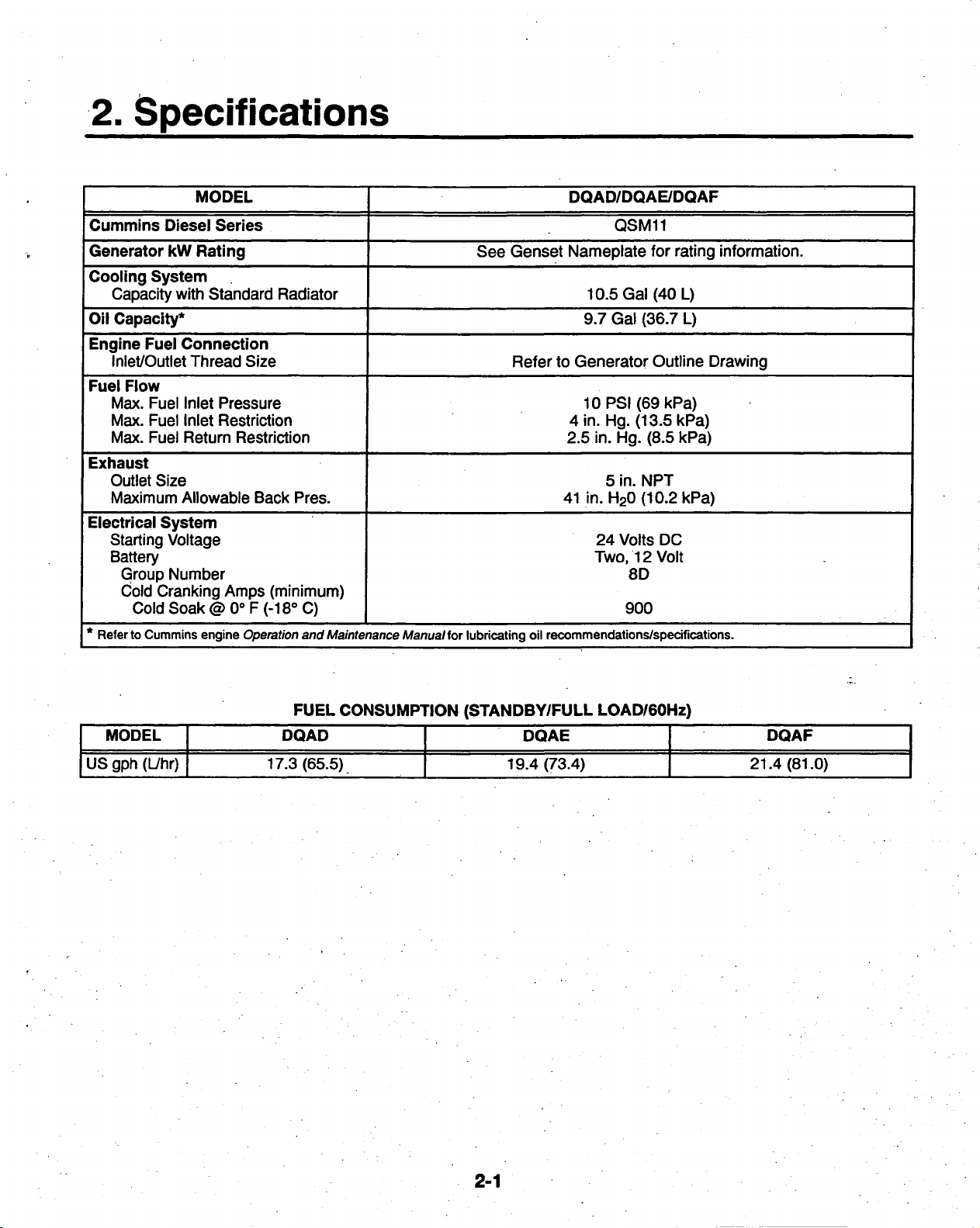
2.
Specifications
MODEL
Cummins
Generator kW Rating See Genset Nameplate for rating information.
Cooling
Capacity with Standard Radiator
Oil
Capacity*
Engine
Inlet/Outlet Thread Size
Fuel
Max. Fuel Inlet Pressure
Max. Fuel Inlet Restriction
Max. Fuel Return Restriction
Exhaust
Outlet Size
Maximum Allowable Back Pres.
Electrical
Starting Voltage
Battery
* Referto Cummins engine Operation and Maintenance Manual for lubricating oil recommendations/specifications.
Diesel
System
Fuel
Flow
System
Group Number
Cold Cranking Amps (minimum)
Cold Soak@0oF(-18o C)
Series
Connection
Refer to Generator Outline Drawing
DQAD/DQAE/DQAF
QSM11
10.5 Gal (40 L)
9.7 Gal (36.7 L)
10PSI(69kPa)
4 in. Hg. (13.5 kPa)
2.5 in. Hg. (8.5 kPa)
5 in. NPT
41 in. H20(10.2kPa)
24 Volts DC
Two,
12 Volt
8D
900
MODEL
US gph (L/hr)
FUEL
CONSUMPTION
DQAD
17.3 (65.5)
(STANDBY/FULL
DQAE
19.4 (73.4)
LOAD/60Hz)
DQAF
21.4(81.0)
2-1

3.
Mounting
the Generator Set
GENERAL
Generator set installations must be engineered so
the generator set will function properly under
pected load
general guide only. Follow the instructions of the
consulting engineer when locating or installing any
components. The complete installation must comply with all local and state building codes, fire ordinances, and other applicable regulations. Consider
these requirements before installation:
Requirements to be considered prior to installation:
• Level mounting surface
• Adequate cooling air
• Adequate fresh induction air
• Discharge of generator set air
• Non-combustible mounting surface.
INCORRECT
PERSONAL
BE
TRAINED AND
PONENT
conditions.
INSTALLATION,
INJURY,
INSTALLATION.
Use these instructions as a
DEATH,
EXPERIENCED
SERVICE
AND/OR EQUIPMENT DAMAGE.
the
ex-
IAWARNING
OR
PARTS
TO
PERFORM
• Discharge of exhaust gases
• Electrical connections
• Accessibility for operation and servicing
• Noise levels
• Vibration isolation
LOCATION
Generator set location is decided mainly by related
systems such as ventilation, wiring, fuel, and exhaust. The set should be located as near as possible to the main power service entrance. Exhaust
must not be able to enter or accumulate around inhabited areas.
Provide a location away from extreme ambient temperatures and protect the generator set from ad-
verse weather conditions.
REPLACEMENT
ELECTRICAL
CAN
SERVICE
AND MECHANICAL COM-
RESULT
PERSONNEL
IN
SEVERE
MUST
DEPENDING
AND
REGULATIONS
BEFORE
POLLUTION
STRUCTION
BEGINNING INSTALLATION OF YOUR
ON YOUR
MAY
CONTROL
PLANS.
LOCATION
REQUIRE
OR AIR QUALITY
AND INTENDED
YOU TO OBTAIN AN AIR QUALITY EMISSIONS PERMIT
IMPORTANT
USE,
GENSET.
AUTHORITIES
3-1
FEDERAL,
BE
SURE
BEFORE
COMPLETING
STATE
TO
OR
LOCAL
CONSULT
YOUR
LAWS
LOCAL
CON-
MOUNTING
Generator sets are mounted on a steel
skid
that provides proper support. The engine-generator assembly is isolated from the skid frame by rubber
mounts that provide adequate vibration isolation for
normal installations. Where required by building
codes or special isolation needs, generator sets
may be mounted on rubber pads or mechanical
spring isolators. The use of unapproved isolators
may result in harmful resonances and may void the
genset warranty.
Mount the generator set on a substantial and level
base such as a concrete pad. A non-combustible
material must be used for the pad.
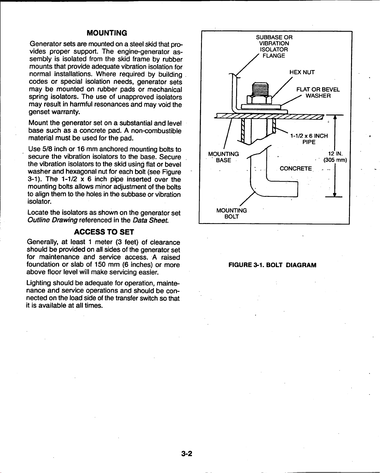
Use 5/8 inch or 16 mm anchored mounting bolts to
secure the vibration isolators to the base. Secure
the vibration isolators to the skid using flat or bevel
washer and hexagonal nut for each bolt (see Figure
3-1). The 1-1/2 x 6 inch pipe inserted over the
mounting bolts allows minor adjustment of the bolts
to align them to the holes
in
the subbase or vibration
isolator.
Locate
Outline Drawing
the
isolators
as
shown
referenced
on the
generator set
in the Data Sheet
MOUNTING
BASE
MOUNTING
BOLT
SUBBASE OR
VIBRATION
ISOLATOR
FLANGE
CONCRETE
HEX NUT
FLAT OR BEVEL
WASHER
1-1/2x6
INCH
PIPE
12 IN.
(305 mm)
ACCESS
TO SET
Generally, at least 1 meter (3 feet) of clearance
should be provided on all sides of the generator set
for maintenance and service access. A raised
foundation or slab of 150 mm (6 inches) or more
above floor level will make servicing easier.
Lighting should be adequate for
nance and service operations and should be
nected on the load side of
the
operation,
mainte-
con-
transfer switch so that
it is available at all times.
FIGURE
3-1.
BOLT DIAGRAM
3-2
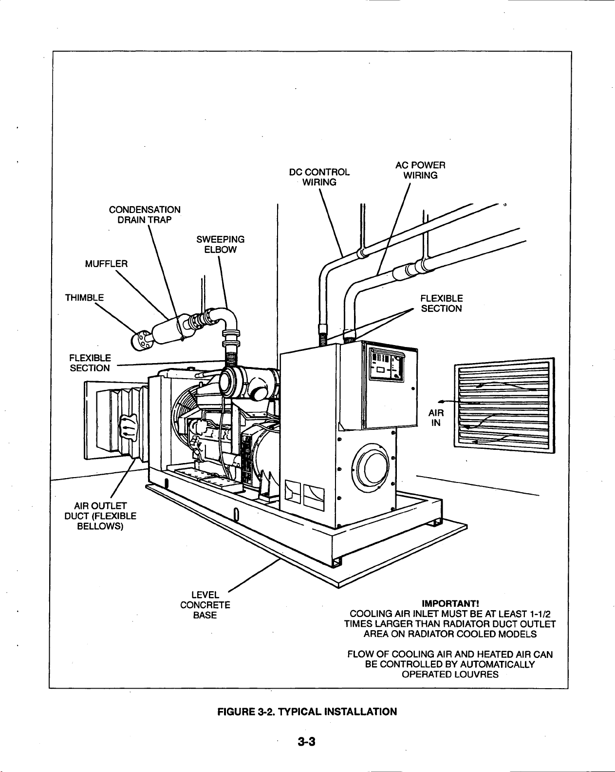
MUFFLER
THIMBLE
FLEXIBLE
SECTION
CONDENSATION
DRAIN TRAP
DC CONTROL
WIRING
AC POWER
WIRING
AIR OUTLET
DUCT (FLEXIBLE
BELLOWS)
LEVEL
CONCRETE
BASE
FIGURE
3-2.
TYPICAL
3-3
IMPORTANT!
COOLING AIR INLET MUST BE AT LEAST 1-1/2
TIMES LARGER THAN RADIATOR DUCT OUTLET
AREA ON RADIATOR COOLED MODELS
FLOW OF COOLING AIR AND HEATED AIR CAN
BE CONTROLLED BY AUTOMATICALLY
OPERATED LOUVRES
INSTALLATION
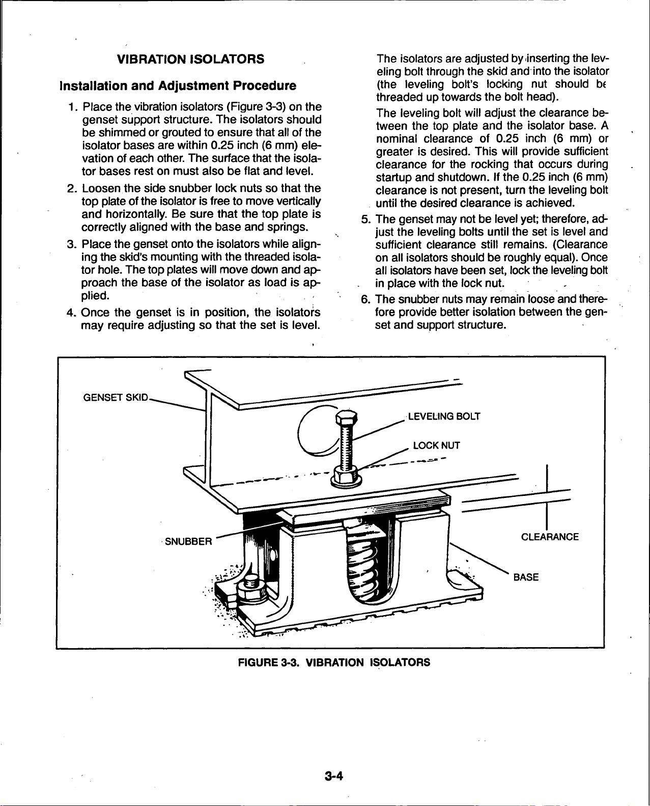
VIBRATION
ISOLATORS
Installation and Adjustment Procedure
1.
Place the vibration isolators (Figure 3-3) on the
genset support structure. The isolators should
be shimmed or grouted to ensure that all of the
isolator bases are within 0.25 inch (6 mm) ele-
vation of each
other.
The surface that the isola-
tor bases rest on must also be flat and level.
2.
Loosen the side snubber lock nuts so that the
top plate ofthe isolator is free to move vertically
and horizontally. Be sure that the top plate is
correctly aligned with the base and springs.
3. Place the genset onto the isolators while aligning the skid's mounting with the threaded isola-
tor
hole.
The top plates will move down and approach the base of the isolator as load is applied.
4.
Once the genset is in position, the isolators
may require adjusting so that the set is level.
The isolators are adjusted by inserting the leveling bolt through the skid and into the isolator
(the leveling bolt's locking nut should be
threaded up towards the bolt head).
The leveling bolt will adjust the clearance be-
tween the top plate and the isolator base. A
nominal clearance of 0.25 inch (6 mm) or
greater is desired. This will provide sufficient
clearance for the rocking that occurs during
startup and shutdown. If the 0.25 inch (6 mm)
clearance is not present, turn the leveling bolt
until the desired clearance is achieved.
5. The genset may not be level
yet;
therefore, adjust the leveling bolts until the set is level and
sufficient clearance still remains. (Clearance
on all isolators should be roughly
all isolators have been set, lock
equal).
the
leveling bolt
in place with the lock nut. -
6. The snubber nuts may remain loose
and
fore provide better isolation between the
set and support structure.
Once
there-
gen-
GENSET SKID.
SNUBBER
FIGURE
3-3. VIBRATION
CLEARANCE
ISOLATORS
3-4
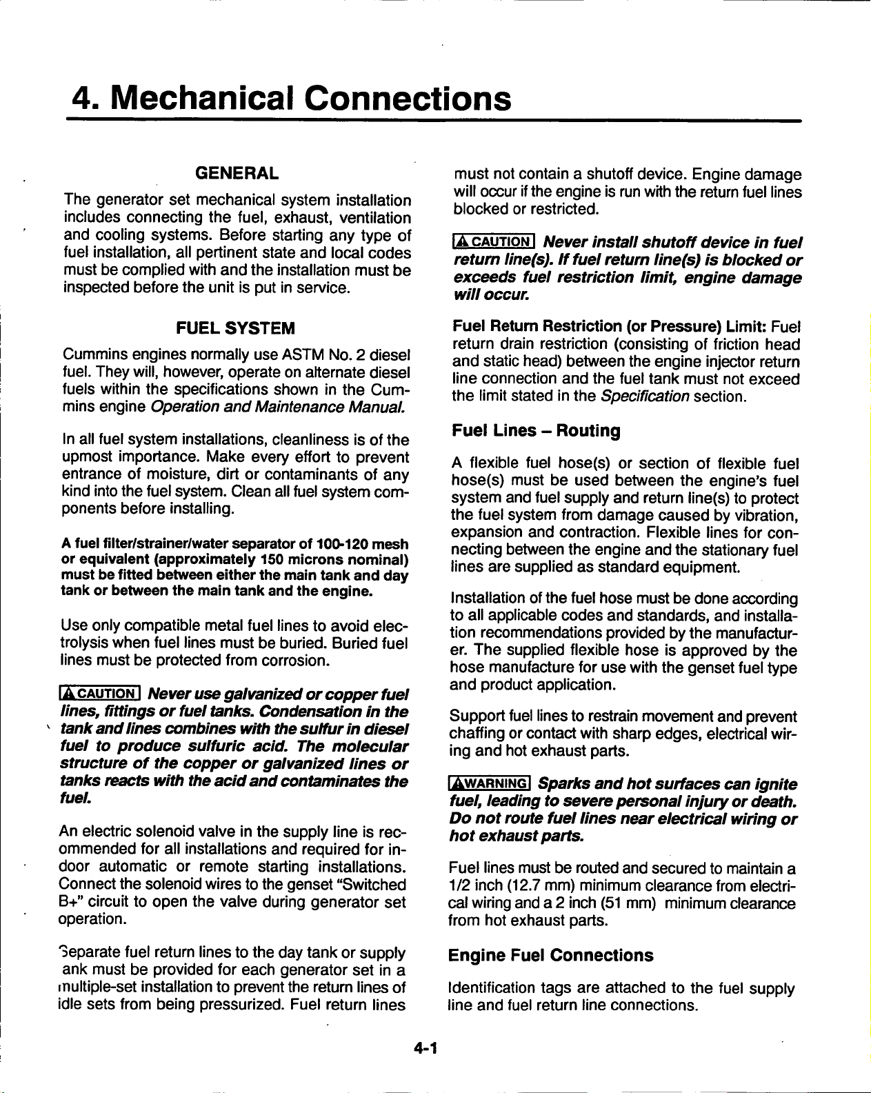
4. Mechanical
Connections
GENERAL
The generator set mechanical system installation
includes connecting the
and cooling systems. Before starting any type of
fuel installation, all pertinent state and local codes
must be complied with and the installation must be
inspected before the unit is put in service.
FUEL
Cummins engines normally use ASTM No. 2 diesel
fuel. They will, however, operate on alternate diesel
fuels within
mins engine Operation and Maintenance Manual.
In all fuel system installations, cleanliness is ofthe
upmost importance. Make every effort to prevent
entrance of moisture, dirt or contaminants of any
kind into the fuel
ponents before installing.
A
fuel filter/strainer/water separator of 100-120 mesh
or equivalent (approximately 150 microns nominal)
must
be
tank or between the main tank
Use only compatible metal fuel lines to avoid elec-
trolysis when fuel lines must be buried. Buried fuel
lines must be protected from corrosion.
IACAUTIONI
lines, fittings
tank and
fuel to produce sulfuric acid. The molecular
structure
tanks reacts with the
fuel.
An electric solenoid valve in the supply line is recommended for all installations and required for indoor automatic or remote starting installations.
Connect the solenoid wires to the genset "Switched
B+"
circuit to open the valve during generator set
operation.
the
specifications shown
system.
fitted between either the main tank and day
Never use galvanized
or
fuel tanks. Condensation
lines combines with the
of the copper or
fuel,
exhaust, ventilation
SYSTEM
in the Cum-
Clean all fuel system com-
and
the engine.
or
copper fuel
sulfur in
galvanized
acid
and contaminates
lines or
in the
diesel
the
must not contain a shutoff
will occur if
blocked or restricted.
IA
retum
exceeds fuel
will
Fuel Retum Restriction (or Pressure) Limit: Fuel
return drain restriction (consisting of friction head
and static head) between the engine injector return
line connection and the fuel tank must not exceed
the limit stated in the Specification section.
Fuel
A flexible fuel hose(s) or section of flexible fuel
hose(s) must be used between the engine's fuel
system and fuel supply and return line(s) to protect
the fuel system from damage caused by vibration,
expansion and contraction. Flexible lines for
necting between the engine and the stationary fuel
lines are supplied as standard equipment.
Installation of
to all applicable codes and standards, and installation recommendations provided by the manufacturer. The supplied flexible hose is approved by the
hose manufacture for use with the genset fuel type
and product application.
Support fuel lines to restrain movement
chaffing or contact with sharp edges, electrical
ing and hot exhaust parts.
IAWARNINGI
fuel,
Do not
hot exhaust parts.
Fuel lines must be routed and secured to maintain a
1/2 inch (12.7 mm) minimum clearance from electrical wiring and a 2 inch
from hot exhaust parts.
CAUTION I
line(s).
occur.
Lines
leading
route
device.
the
engine is
Never
If
fuel return
restriction
- Routing
the
fuel hose must be done according
Sparks
to
severe personal injury
fuel
install
and hot
lines
(51
run
with the return fuel lines
shutoff
limit, engine damage
near
mm) minimum clearance
Engine damage
device
linefs) is
surfaces can
electrical wiring
blocked
and
prevent
or
in fuel
or
con-
wir-
ignite
death.
or
Separate fuel return lines to the day tank or supply
ank must be provided for each generator set in a
multiple-set installation to prevent the return lines of
idle sets from being pressurized. Fuel return lines
Engine
Identification tags are attached to the fuel supply
line and fuel return line connections.
Fuel
Connections
4-1
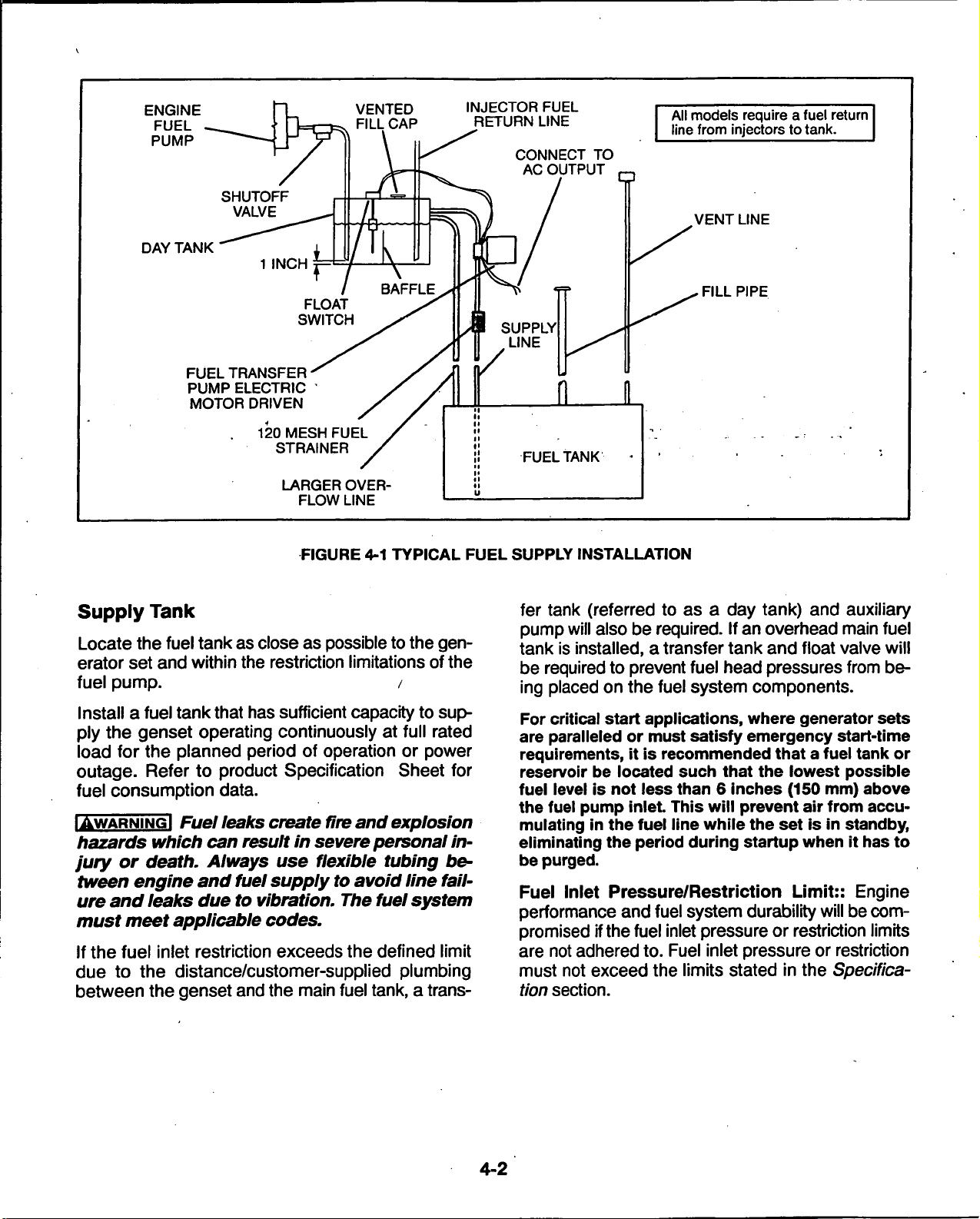
ENGINE
FUEL
PUMP
DAY TANK
FUEL TRANSFER•
PUMP ELECTRIC '
MOTOR DRIVEN
VENTED
FILL CAP
120 MESH FUEL
STRAINER
LARGER OVER-
FLOW LINE
INJECTOR FUEL
RETURN LINE
CONNECT TO
AC OUTPUT
FUELTANK
All models require a fuel return
line from injectors to tank.
VENT LINE
. FILL PIPE
FIGURE 4-1 TYPICAL FUEL SUPPLY INSTALLATION
Supply
Tank
fer tank (referred to as a day tank) and auxiliary
pump will also be required. If an overhead main fuel
Locate the fuel tank as close as possible to the
erator set and within the restriction limitations of the
fuel pump. /
Install a fuel tank that has sufficient capacity to supply the genset operating continuously at full rated
load for the planned period of operation or power
outage. Refer to product Specification Sheet for
fuel consumption data.
gen-
tank is installed, a transfer tank and float valve will
be required to prevent fuel head pressures from be-
ing placed on the fuel system components.
For critical start applications, where generator sets
are paralleled or must satisfy emergency start-time
requirements, it is recommended that a fuel tank or
reservoir be located such that the lowest possible
fuel level is not less than 6 inches (150 mm) above
the fuel pump inlet This will prevent air from accu-
IAWARNINGI Fuel leaks create fire and explosion
hazards which can result in severe personal in-
jury or death. Always use flexible tubing be-
tween engine and fuel supply to avoid line failure and leaks due to vibration. The fuel system
must meet applicable codes.
If the fuel inlet restriction exceeds the defined limit
due to the distance/customer-supplied plumbing
between the genset and the main fuel tank, a trans-
mulating in the fuel line while the set is in standby,
eliminating the period during startup when it has to
be purged.
Fuel Inlet Pressure/Restriction Limit:: Engine
performance and fuel system durability will be compromised ifthe fuel inlet pressure or restriction limits
are not adhered to. Fuel inlet pressure or restriction
must not exceed the limits stated in the Specification section.
4-2
 Loading...