

CUMMINS DGBA, DGBB, DGCB, DGDA, DGDB Service Manual
...
Caution: This document contains mixed page sizes (8.5 x 11 or 11 x
Redistribution or publication of this document
by any means, is strictly prohibited.
Redistribution or publication of this document
by any means, is strictly prohibited.
17), which may affect printing. Please adjust your printer settings
according to the size of each page you wish to print.
Service Manual
Redistribution or publication of this document
by any means, is strictly prohibited.
Redistribution or publication of this document
by any means, is strictly prohibited.
Detector Control
Generator Sets
Printed in U.S.A.
Models
DGBA, DGBB, DGBC, DGCA, DGCB, DGDA, DGDB
DGEA, DGFA, DGFB
QSGBA, QSGCA, QSGCB, QSDA, QSDB, QSEA, QSFA
4B3.9, 4BT3.9, 6BT5.9, 6CT8.3, 6CTA8.3
960-0505 4-2001

Table of Contents
Redistribution or publication of this document
by any means, is strictly prohibited.
Redistribution or publication of this document
by any means, is strictly prohibited.
SECTION TITLE PAGE
SAFETY PRECAUTIONS iii. . . . . . . . . . . . . . . . . . . . . . . . . . . . . . . . . . . . . . . . . . .
1 INTRODUCTION 1-1. . . . . . . . . . . . . . . . . . . . . . . . . . . . . . . . . . . . . . . . . . . . . . . . . .
About This Manual 1-1. . . . . . . . . . . . . . . . . . . . . . . . . . . . . . . . . . . . . . . . . . . . . . .
Test Equipment 1-1. . . . . . . . . . . . . . . . . . . . . . . . . . . . . . . . . . . . . . . . . . . . . . . . . .
2 AC CONTROL 2-1. . . . . . . . . . . . . . . . . . . . . . . . . . . . . . . . . . . . . . . . . . . . . . . . . . . .
General 2-1. . . . . . . . . . . . . . . . . . . . . . . . . . . . . . . . . . . . . . . . . . . . . . . . . . . . . . . .
Standard Control Panel Components 2-1. . . . . . . . . . . . . . . . . . . . . . . . . . . . . . .
Optional Control Panel Components 2-1. . . . . . . . . . . . . . . . . . . . . . . . . . . . . . .
Automatic Voltage Regulator (AVR) Adjustments 2-2. . . . . . . . . . . . . . . . . . . . .
Principle Of Generator Operation 2-7. . . . . . . . . . . . . . . . . . . . . . . . . . . . . . . . . .
3 ENGINE CONTROL 3-1. . . . . . . . . . . . . . . . . . . . . . . . . . . . . . . . . . . . . . . . . . . . . . .
Control Panel 3-1. . . . . . . . . . . . . . . . . . . . . . . . . . . . . . . . . . . . . . . . . . . . . . . . . . .
Standard Control Panel Components 3-1. . . . . . . . . . . . . . . . . . . . . . . . . . . . . . .
Optional Control Panel Components 3-2. . . . . . . . . . . . . . . . . . . . . . . . . . . . . . .
Control Box Interior 3-3. . . . . . . . . . . . . . . . . . . . . . . . . . . . . . . . . . . . . . . . . . . . . .
Engine Control Monitor (A11) 3-4. . . . . . . . . . . . . . . . . . . . . . . . . . . . . . . . . . . . . .
Engine Sensors 3-6. . . . . . . . . . . . . . . . . . . . . . . . . . . . . . . . . . . . . . . . . . . . . . . . .
Auxiliary Control Components 3-10. . . . . . . . . . . . . . . . . . . . . . . . . . . . . . . . . . . .
Sequence Of Operation 3-16. . . . . . . . . . . . . . . . . . . . . . . . . . . . . . . . . . . . . . . . .
4 TROUBLESHOOTING 4-1. . . . . . . . . . . . . . . . . . . . . . . . . . . . . . . . . . . . . . . . . . . . .
The Engine Does Not Crank 4-1. . . . . . . . . . . . . . . . . . . . . . . . . . . . . . . . . . . . . .
The Engine Cranks But Does Not Start 4-4. . . . . . . . . . . . . . . . . . . . . . . . . . . .
The Engine Runs Until Fault Shutdown (Red Shutdown Lamp On) 4-6. . . . .
The Engine Lacks Power Or Stable Speed 4-8. . . . . . . . . . . . . . . . . . . . . . . . .
Amber Warning Lamp On 4-10. . . . . . . . . . . . . . . . . . . . . . . . . . . . . . . . . . . . . . .
The Green Run Lamps Stay Off But The Set Runs Normally 4-11. . . . . . . . .
There Is No Output Voltage (Engine Speed Is Stable) 4-12. . . . . . . . . . . . . . .
Output Voltage Is Too High Or Too Low 4-16. . . . . . . . . . . . . . . . . . . . . . . . . . .
Output Voltage Is Unstable 4-17. . . . . . . . . . . . . . . . . . . . . . . . . . . . . . . . . . . . . .
The Field Circuit Breaker Keeps Tripping 4-18. . . . . . . . . . . . . . . . . . . . . . . . . .
The Phase Currents Are Unbalanced 4-19. . . . . . . . . . . . . . . . . . . . . . . . . . . . .
i

5 SERVICING THE GENERATOR 5-1. . . . . . . . . . . . . . . . . . . . . . . . . . . . . . . . . . . . .
Redistribution or publication of this document
by any means, is strictly prohibited.
Redistribution or publication of this document
by any means, is strictly prohibited.
Testing The Generator 5-1. . . . . . . . . . . . . . . . . . . . . . . . . . . . . . . . . . . . . . . . . . .
Removing And Disassembling The Generator 5-8. . . . . . . . . . . . . . . . . . . . . . .
Reassembling The Generator 5-10. . . . . . . . . . . . . . . . . . . . . . . . . . . . . . . . . . . .
Servicing The PMG 5-10. . . . . . . . . . . . . . . . . . . . . . . . . . . . . . . . . . . . . . . . . . . . .
6 GOVERNORS 6-1. . . . . . . . . . . . . . . . . . . . . . . . . . . . . . . . . . . . . . . . . . . . . . . . . . . .
Mechanical Governor 6-1. . . . . . . . . . . . . . . . . . . . . . . . . . . . . . . . . . . . . . . . . . . .
Electric Governor 6-4. . . . . . . . . . . . . . . . . . . . . . . . . . . . . . . . . . . . . . . . . . . . . . . .
7 DAY TANK FUEL PUMP AND CONTROL 7-1. . . . . . . . . . . . . . . . . . . . . . . . . . . .
Operation 7-2. . . . . . . . . . . . . . . . . . . . . . . . . . . . . . . . . . . . . . . . . . . . . . . . . . . . . . .
Wiring Connections 7-4. . . . . . . . . . . . . . . . . . . . . . . . . . . . . . . . . . . . . . . . . . . . . .
Fuel Transfer Pump Motor Connections 7-5. . . . . . . . . . . . . . . . . . . . . . . . . . . .
Testing The Float Switch Assembly 7-6. . . . . . . . . . . . . . . . . . . . . . . . . . . . . . . .
8 QS- AND QSG-SERIES GENERATOR SETS 8-1. . . . . . . . . . . . . . . . . . . . . . . . .
Optional Power Distribution Panel for QSG-Series 8-1. . . . . . . . . . . . . . . . . . .
Optional Trailer Package for QS- and QSG-Series 8-3. . . . . . . . . . . . . . . . . . .
Fan Belt Replacement Procedure for QSG-Series 8-5. . . . . . . . . . . . . . . . . . .
Blower Replacement Procedure for QS-Series 8-6. . . . . . . . . . . . . . . . . . . . . .
9 WIRING DIAGRAMS 9-1. . . . . . . . . . . . . . . . . . . . . . . . . . . . . . . . . . . . . . . . . . . . . .
ii
IMPORTANT SAFETY INSTRUCTIONS
Redistribution or publication of this document
by any means, is strictly prohibited.
Redistribution or publication of this document
by any means, is strictly prohibited.
SAVE THESE INSTRUCTIONS − This manual contains
important instructions that should be followed during
installation and maintenance of the generator and batteries.
Before operating the generator set (genset), read the
Operator’s Manual and become familiar with it and the
equipment. Safe and efficient operation can be
achieved only if the equipment is properly operated
and maintained. Many accidents are caused by failure
to follow fundamental rules and precautions.
The following symbols, found throughout this manual,
alert you to potentially dangerous conditions to the operator, service personnel, or the equipment.
This symbol warns of immediate
hazards which will result in severe personal injury or death.
WARNING
This symbol refers to a hazard or unsafe practice which can result in severe personal injury or death.
CAUTION
This symbol refers to a hazard or unsafe practice which can result in personal injury
or product or property damage.
FUEL AND FUMES ARE FLAMMABLE
Fire, explosion, and personal injury or death can result
from improper practices.
• DO NOT fill fuel tanks while engine is running, un-
less tanks are outside the engine compartment.
Fuel contact with hot engine or exhaust is a potential
fire hazard.
• DO NOT permit any flame, cigarette, pilot light,
spark, arcing equipment, or other ignition source
near the generator set or fuel tank.
• Fuel lines must be adequately secured and free of
leaks. Fuel connection at the engine should be
made with an approved flexible line. Do not use zinc
coated or copper fuel lines with diesel fuel.
• Be sure all fuel supplies have a positive shutoff
valve.
• Be sure battery area has been well-ventilated prior
to servicing near it. Lead-acid batteries emit a highly
explosive hydrogen gas that can be ignited by arcing, sparking, smoking, etc.
EXHAUST GASES ARE DEADLY
Provide an adequate exhaust system to properly
•
expel discharged gases away from enclosed or
sheltered areas and areas where individuals are
likely to congregate. Visually and audibly inspect
the exhaust daily for leaks per the maintenance
schedule. Make sure that exhaust manifolds are secured and not warped. Do not use exhaust gases to
heat a compartment.
• Be sure the unit is well ventilated.
• Engine exhaust and some of its constituents are
known to the state of California to cause cancer,
birth defects, and other reproductive harm.
MOVING PARTS CAN CAUSE SEVERE
PERSONAL INJURY OR DEATH
•
Keep your hands, clothing, and jewelry away from
moving parts.
• Before starting work on the generator set, discon-
nect battery charger from its AC source, then disconnect starting batteries, negative (−) cable first.
This will prevent accidental starting.
• Make sure that fasteners on the generator set are
secure. Tighten supports and clamps, keep guards
in position over fans, drive belts, etc.
• Do not wear loose clothing or jewelry in the vicinity of
moving parts, or while working on electrical equipment. Loose clothing and jewelry can become
caught in moving parts.
• If adjustment must be made while the unit is run-
ning, use extreme caution around hot manifolds,
moving parts, etc.
DO NOT OPERATE IN FLAMMABLE AND
EXPLOSIVE ENVIRONMENTS
Flammable vapor can cause an engine to overspeed and
become difficult to stop, resulting in possible fire, explosion, severe personal injury and death. Do not operate a
genset where a flammable vapor environment can be
created by fuel spill, leak, etc., unless the genset is
equipped with an automatic safety device to block the air
intake and stop the engine. The owners and operators of
the genset are solely responsible for operating the genset safely. Contact your authorized Onan/Cummins dealer or distributor for more information.
LS-13M
iii

ELECTRICAL SHOCK CAN CAUSE
Redistribution or publication of this document
by any means, is strictly prohibited.
Redistribution or publication of this document
by any means, is strictly prohibited.
SEVERE PERSONAL INJURY OR DEATH
•
Remove electric power before removing protective
shields or touching electrical equipment. Use rubber insulative mats placed on dry wood platforms
over floors that are metal or concrete when around
electrical equipment. Do not wear damp clothing
(particularly wet shoes) or allow skin surface to be
damp when handling electrical equipment. Do not
wear jewelry. Jewelry can short out electrical contacts and cause shock or burning.
• Use extreme caution when working on electrical
components. High voltages can cause injury or
death. DO NOT tamper with interlocks.
• Follow all applicable state and local electrical
codes. Have all electrical installations performed by
a qualified licensed electrician. Tag and lock open
switches to avoid accidental closure.
• DO NOT CONNECT GENERATOR SET DIRECT-
LY TO ANY BUILDING ELECTRICAL SYSTEM.
Hazardous voltages can flow from the generator set
into the utility line. This creates a potential for electrocution or property damage. Connect only
through an approved isolation switch or an approved paralleling device.
MEDIUM VOLTAGE GENERATOR SETS
(601V to 15kV)
Medium voltage acts differently than low voltage.
•
Special equipment and training is required to work
on or around medium voltage equipment. Operation
and maintenance must be done only by persons
trained and qualified to work on such devices. Improper use or procedures will result in severe personal injury or death.
• Do not work on energized equipment. Unauthorized
personnel must not be permitted near energized
equipment. Due to the nature of medium voltage
electrical equipment, induced voltage remains even
after the equipment is disconnected from the power
source. Plan the time for maintenance with authorized personnel so that the equipment can be de-energized and safely grounded.
GENERAL SAFETY PRECAUTIONS
Coolants under pressure have a higher boiling point
•
than water. DO NOT open a radiator or heat exchanger pressure cap while the engine is running.
Allow the generator set to cool and bleed the system
pressure first.
• Used engine oils have been identified by some state
or federal agencies as causing cancer or reproductive toxicity . When checking or changing engine oil,
take care not to ingest, breathe the fumes, or contact used oil.
• Keep multi-class ABC fire extinguishers handy.
Class A fires involve ordinary combustible materials
such as wood and cloth; Class B fires, combustible
and flammable liquid fuels and gaseous fuels; Class
C fires, live electrical equipment. (ref. NFP A No. 10).
• Make sure that rags are not left on or near the en-
gine.
• Make sure generator set is mounted in a manner to
prevent combustible materials from accumulating
under the unit.
• Remove all unnecessary grease and oil from the
unit. Accumulated grease and oil can cause overheating and engine damage which present a potential fire hazard.
• Keep the generator set and the surrounding area
clean and free from obstructions. Remove any debris from the set and keep the floor clean and dry.
• Do not work on this equipment when mentally or
physically fatigued, or after consuming any alcohol
or drug that makes the operation of equipment unsafe.
• Substances in exhaust gases have been identified
by some state or federal agencies as causing cancer or reproductive toxicity. Take care not to breath
or ingest or come into contact with exhaust gases.
• Do not store any flammable liquids, such as fuel,
cleaners, oil, etc., near the generator set. A fire or
explosion could result.
• Wear hearing protection when going near an oper-
ating generator set.
• To prevent serious burns, avoid contact with hot
metal parts such as radiator, turbo charger and exhaust system.
KEEP THIS MANUAL NEAR THE GENSET FOR EASY REFERENCE
iv
1. Introduction
Redistribution or publication of this document
by any means, is strictly prohibited.
Redistribution or publication of this document
by any means, is strictly prohibited.
GENERAL
This manual covers models produced under the
Cummins
tion brand names.
Each operator should read this manual before operating the set for the first time. A generator set (genset) must be operated and maintained properly if
you are to expect safe, reliable and quiet operation.
The manual includes a troubleshooting guide and a
maintenance schedule.
The engine manual is included with the set. Where
there is conflicting information, this manual takes
precedence over the engine manual.
WARNING
nance can lead to severe personal injury or loss
of life and property by fire, electrocution, mechanical breakdown or exhaust gas asphyxiation. Read and follow the safety precautions
on page iii and carefully observe all instructions
and precautions in this manual.
/Onan and Cummins Power Genera-
Improper operation and mainte-
tor. Factory-trained Parts and Service representatives are ready to handle all your service needs.
To contact your local Cummins Power Generation
distributor in the United States or Canada, call
1-800-888-6626 (this automated service utilizes
touch-tone phones only). By selecting Option 1
(press 1), you will be automatically connected to the
distributor nearest you.
If you are unable to contact a distributor using the
automated service, consult the Yellow Pages. Typically, our distributors are listed under:
GENERATORS-ELECTRIC or
ELECTRICAL PRODUCTS
For outside North America, call Cummins Power
Generation, 1-763-574-5000, 7:30 AM to 4:00 PM,
Central Standard Time, Monday through Friday. O r,
send a fax to Cummins Power Generation using the
fax number 1-763-574-8087.
HOW TO OBTAIN SERVICE
When contacting your distributor, always supply the
When the generator set requires servicing, contact
your nearest Cummins Power Generation distribu-
complete Model, Specification, and Serial Number
as shown on the generator set nameplate.
WARNING
INCORRECT SERVICE OR PARTS REPLACEMENT CAN RESULT IN SEVERE PERSONAL INJURY, DEATH, AND/OR EQUIPMENT DAMAGE. SERVICE PERSONNEL MUST BE TRAINED
AND EXPERIENCED TO PERFORM ELECTRICAL AND/OR MECHANICAL SERVICE.
Copyright2001 Cummins Power Generation. All rights reserved.
Cummins and Onan are registered trademarks of Cummins Inc.
Detector is a trademark of Cummins Inc.
1-1

THIS PAGE LEFT INTENTIONALLY BLANK
Redistribution or publication of this document
by any means, is strictly prohibited.
Redistribution or publication of this document
by any means, is strictly prohibited.
1-2
2. AC Control
Redistribution or publication of this document
by any means, is strictly prohibited.
Redistribution or publication of this document
by any means, is strictly prohibited.
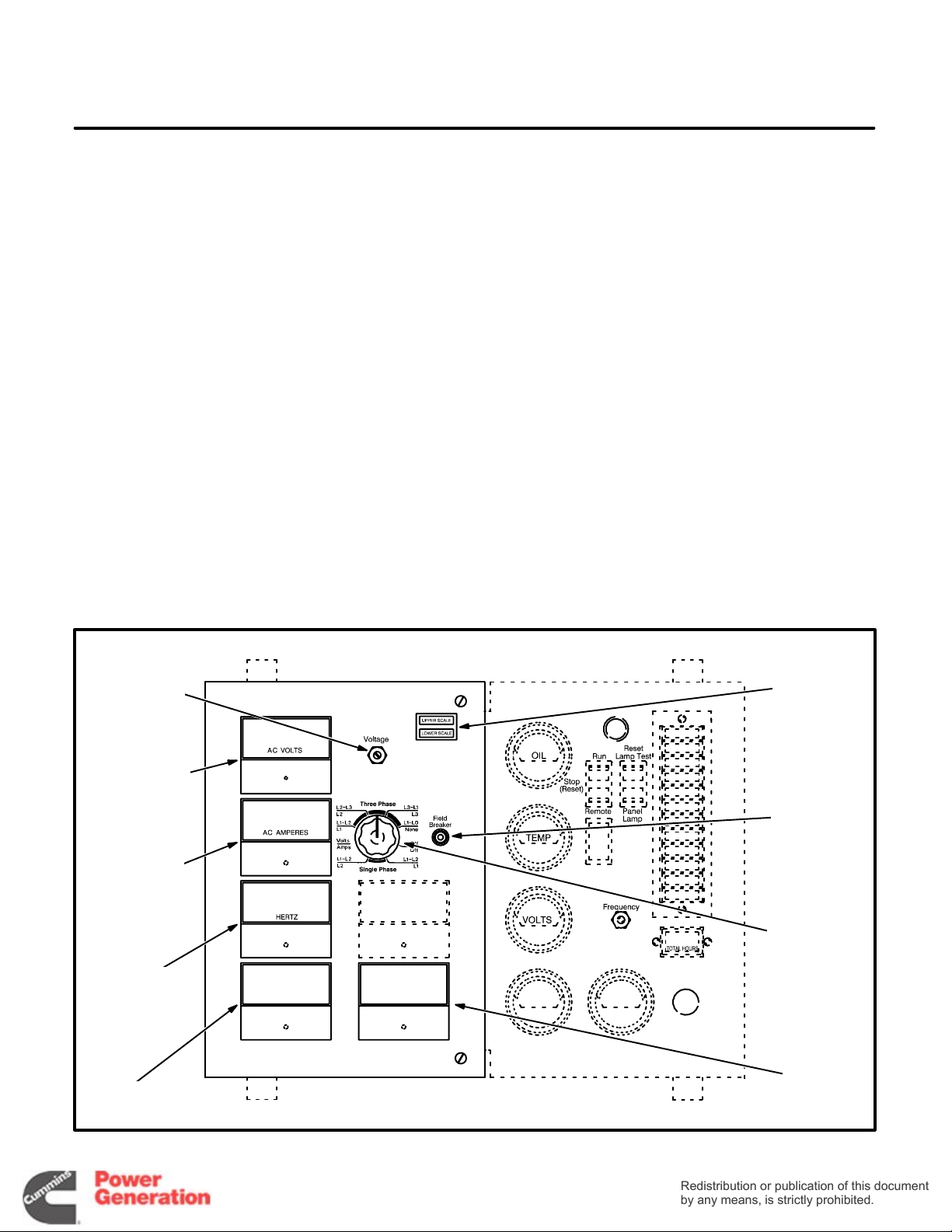
GENERAL
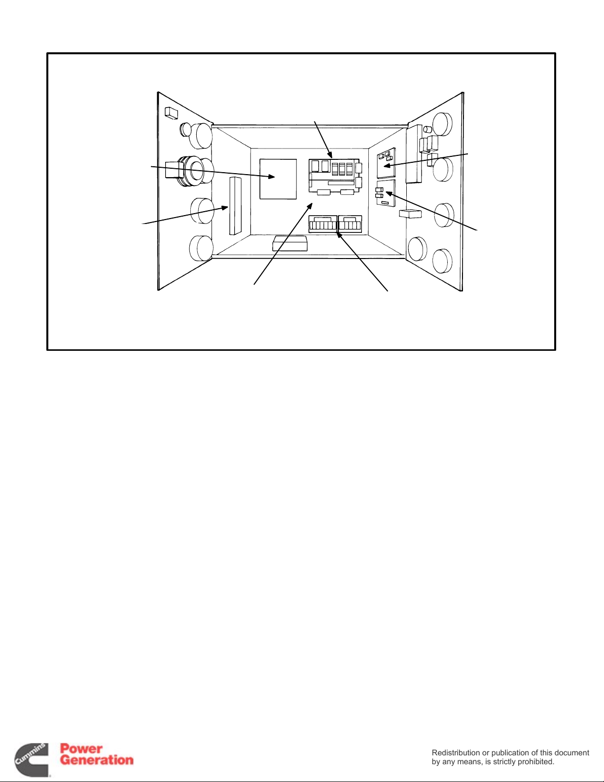
The control box is mounted on top of the generator,
facing the rear. Figure 2-1 points out the components on the AC control panel. Pages 9-3 through
9-6 show the wiring connections.
STANDARD CONTROL PANEL
COMPONENTS
Field Circuit Breaker (CB21) The field circuit
breaker protects the generator from over-excitation.
OPTIONAL CONTROL PANEL
COMPONENTS
AC V oltmeter (M21) The voltmeter indicates output
voltage for the phase selected.
AC Ammeter (M22) The ammeter indicates output
amperage for the phase selected. Input to the am-
meter is from current transformers CT21, CT22 and
CT23.
Phase Selector Switch (S21) The selector switch
is used to select the phase for voltage and amper-
age readings.
Scale Indicator Lamps (DS21 and DS22) The
scale indicator lamps indicate whether to read the
upper or lower scales of the voltmeter and ammeter .
Frequency Meter (M23) The frequency meter indi-
cates output frequency in Hertz (Hz) and engine
speed in RPM.
Wattmeter (M24) The wattmeter indicates output
power in kilowatts (kW).
Powerfactor Meter (M25)
The powerfactor meter
indicates output powerfactor as a percentage of
unity powerfactor.
Output V oltage T rimmer (R21) The output voltage
trimmer can be used to adjust output voltage plus or
minus five percent of nominal voltage.
OUTPUT
VOLTAGE
TRIMMER
AC
VOLTMETER
AC
AMMETER
FREQUENCY
METER
WATTMETER
SCALE
INDICATOR
LAMPS
FIELD
CIRCUIT
BREAKER
PHASE
SELECTOR
SWITCH
POWER
FACTOR
METER
FIGURE 2-1. AC CONTROL PANEL
2-1

AUTOMATIC VOLTAGE REGULATOR
Redistribution or publication of this document
by any means, is strictly prohibited.
Redistribution or publication of this document
by any means, is strictly prohibited.
(AVR) ADJUSTMENTS
Check and readjust the VOLTS pot, if necessary,
each time the STABILITY pot is readjusted.
The automatic voltage regulator is mounted on the
back wall of the control cabinet. It can be adjusted
by means of the potentiometers (pots) shown in Figure 2-2 or 2-3. Figures 2-4 and 2-5 show typical voltage regulating circuits.
These measurements and adjustments are done
while the set is running and require access to uninsulated high voltage parts in the control and power
output boxes.
HIGH VOLTAGE. Touching uninsulated high voltage parts inside the control and
power output boxes can result in severe personal injury or death. Measurements and adjustments must be done with care to avoid
touching high voltage parts.
For your protection, stand on a dry wooden platform or rubber insulating mat, make sure your
clothing and shoes are dry , remove jewelry from
your hands and wear elbow length insulating
gloves.
Jumper Reconnections
Jumpers provide for reconnections to adapt the
voltage regulator to the application. See Figure 2-2.
Reconnect the response jumper, if necessary, so
that terminal A connects to terminal C if generator
output is 90 kW o r less, B to C if generator output is
greater than 90 kW but less than 550 kW and A to B
if output is greater than 550kW. Reconnect the frequency jumper, if necessary, to correspond to the
application frequency.
Voltage and Voltage Stability Adjustments
Use the control panel mounted voltage trimmer, if
provided, for small voltage adjustments. Measure
generator output voltage while the set is running
without load at the nominal frequency. If the trimmer
does not provide enough adjustment, lock it at its
midpoint. Then turn the VOLTS pot fully counter-
clockwise and the STABILITY pot to its midpoint. If
the red LED (light emitting diode) on the board
lights, refer to Jumper Reconnections and to UFRO
Adjustments. Then turn the VOLTS pot clockwise
until rated voltage is obtained. If voltage becomes
unstable when a large load is connected, turn the
STABILITY pot clockwise until voltage is stable.
UFRO Adjustments
The voltage regulator has an under-frequency
protection circuit having a threshold frequency that
can be preset (typically at 59 Hz for 60 Hz applications and 49 Hz for 50 Hz applications). The red
LED on the board lights when frequency dips below
the threshold. The threshold frequency is preset by
turning the UFRO (under frequency roll off) pot
clockwise to raise it and counterclockwise to lower
it. Determine threshold frequency by lowering generator frequency until the LED lights. Note that Dip
and Dwell adjustments, below, are related.
Dip Adjustments
The DIP pot adjusts the voltage vs. frequency slope
of the generator for frequencies below the threshold
preset by the UFRO pot. Turning the DIP pot clockwise increases the slope (for greater voltage roll off
as frequency drops), making it easier for the engine
to pick up a large load, but also increasing the voltage dip. The generator voltage vs. frequency slope
is the same above and below the threshold frequency when the pot is turned fully counterclockwise.
Dwell Adjustments
The DWELL pot times voltage recovery when frequency dips below the preset threshold. Clockwise
adjustment increases dwell time. Full counterclockwise adjustment eliminates dwell, in which case,
voltage recovery follows engine speed recovery.
Droop Adjustments
The DROOP pot is for adjusting the input signal
from the droop compensating CT in paralleling applications. DROOP is preset at the factory for five
percent droop at full load and zero power factor.
V / Trim Adjustments
The V / Trim pot is for adjusting the input signal from
a VAR / PF controller in utility paralleling applications. Full clockwise adjustment is normal, resulting
in maximum sensitivity . The auxiliary controller has
no effect when the pot is turned fully counterclockwise.
EXC, OVER V, I / LIMIT, STAB/1and RMS
These pots are factory preset and do not require adjustment.
2-2
PMG-EXCITED GENERATORS
Redistribution or publication of this document
by any means, is strictly prohibited.
Redistribution or publication of this document
by any means, is strictly prohibited.
I/LIMIT
VOLTS
LED
1
2
3
UFRO
MX321
DIP
V/TRIM
DROOP
STABILITY
DWELL
EXC
OVER V
VOLTAGE REGULATOR
(VR21)
FREQUENCY JUMPER:
50 HZ—3-2
60 HZ—3-1
A
B
C
RESPONSE JUMPER:
A TO C—UNDER 90 KW
B TO C—90-550 KW
A TO B—OVER 550 KW
SELF-EXCITED GENERATORS
ABC
60C 50
UFRO
LED
STABILITY
RESPONSE JUMPER:
A TO C—UNDER 90 KW
B TO C—90-550 KW
A TO B—OVER 550 KW
FREQUENCY JUMPER:
50 HZ—C-50
60 HZ—C-60
THESE JUMPERS
MUST BE:
2-3, 4-5 AND 6-7
FIGURE 2-2. VOLTAGE REGULATOR ADJUSTMENT POTS AND SELECTION JUMPERS
(BEGINNING JANUARY 1990)
2-3
8
7
6
5
4
3
2
1
SX440
VOLTS
DROOP
V/TRIM
PMG-EXCITED GENERATORS
Redistribution or publication of this document
by any means, is strictly prohibited.
Redistribution or publication of this document
by any means, is strictly prohibited.
I/LIMIT
VOLTS
UFRO
DIP
LED
STABILITY
STAB/1
RMS
V/TRIM
DROOP
EXC
OVER V
VOLTAGE REGULATOR
(VR21)
SELF-EXCITED GENERATORS
60C 50
UFRO
LED
FREQUENCY JUMPER:
50 HZ—C-50
60 HZ—C-60
THESE JUMPERS
MUST BE:
2-3, 4-5 AND 6-7
FIGURE 2-3. VOLTAGE REGULATOR ADJUSTMENT POTS AND SELECTION JUMPERS
(PRIOR TO JANUARY 1990)
2-4
8
7
6
5
4
3
2
1
STABILITY
VOLTS
DROOP
V/TRIM
PMG
Redistribution or publication of this document
by any means, is strictly prohibited.
Redistribution or publication of this document
by any means, is strictly prohibited.
ROTOR
N
S
PMG
STATOR
EXCITER
ROTOR
EXCITER
STATOR
ROTATING
RECTIFIERS
MAIN
ROTOR
MAIN
STATOR
8
7
6
OUTPUT
VOLTAGE
SENSING
LEADS
(NOTE 2)
TB21
32
6
25
24
7
23
8
22
21
VOLTAGE
TRIMMER R21
(NOTE 4)
FIELD CIRCUIT
BREAKER
CB21
ISOLATION TRANSFORMER
(NOTE 3)
INPUT OUTPUT
786− 786−
2
1
8
7
6
X
VOLTAGE
XX
REGULATOR
P4
P3
P2
K1
K2
MX321
(VR21)
K1K2 P2 P3 P4 S2 S1 A2 A1XXXX 8 7 6 3 2 1
X
AUXILIARY TERMINAL BOARD
A2
A1
S2
S1
E1
E0
WHEN PARALLELING WITH
A GENERATOR SET OR
UTILITY, TERMINALS S1
AND S2 ARE FOR
CONNECTING A DROOP
COMPENSATING CT
WHEN PARALLELING WITH
A UTILITY, TERMINALS A1
AND A2 ARE FOR
CONNECTING A
VAR / POWER FACTOR
CONTROLLER
1. Connect like numbered terminals on auxiliary
terminal board and voltage regulator.
2. See the appropriate reconnection diagram for
connecting sensing leads 6, 7 and 8.
3. When the generator is connected for singlephase output, voltage regulator terminal 6 is
FIGURE 2-4. TYPICAL VOLTAGE REGULATING CIRCUITS FOR PMG-EXCITED GENERATORS
— NOTES —
not connected to the isolation transformer but
is jumpered to voltage regulator terminal 8.
4. There must be a jumper between voltage regulator terminals 1 and 2 when voltage trimmer
R21 is not used.
2-5
EXCITER
Redistribution or publication of this document
by any means, is strictly prohibited.
Redistribution or publication of this document
by any means, is strictly prohibited.
ROTOR
ROTATING
RECTIFIERS
MAIN
ROTOR
6
7
8
EXCITER
STATOR
TB21
32
25
24
23
22
21
SX440
VOLTAGE
REGULATOR
S2
S1
A2
A1
(VR21)
21 P4 P2P3
3
MAIN
STATOR
OUTPUT
8
VOLTAGE
7
SENSING
LEADS
6
(NOTE 2)
K1K2 P2 P3 P4 S2 S1 A2 A1XXXX 8 7 6 3 2 1
X
AUXILIARY TERMINAL BOARD
WHEN PARALLELING WITH
A GENERATOR SET OR
UTILITY, TERMINALS S1
K1K2XXX
AND S2 ARE FOR
CONNECTING A DROOP
COMPENSATING CT
VOLTAGE
TRIMMER R21
(NOTE 3)
1. Connect like numbered terminals on auxiliary
terminal board and voltage regulator.
2. See the appropriate reconnection diagram for
connecting sensing leads 6, 7 and 8.
FIGURE 2-5. TYPICAL VOLTAGE REGULATING CIRCUITS FOR SELF-EXCITED GENERATORS
— NOTES —
3. There must be a jumper between voltage regu-
2-6
WHEN PARALLELING WITH
A UTILITY, TERMINALS A1
AND A2 ARE FOR
FIELD CIRCUIT
BREAKER
CB21
CONNECTING A
VAR / POWER FACTOR
CONTROLLER
lator terminals 1 and 2 when voltage trimmer
R21 is not used.
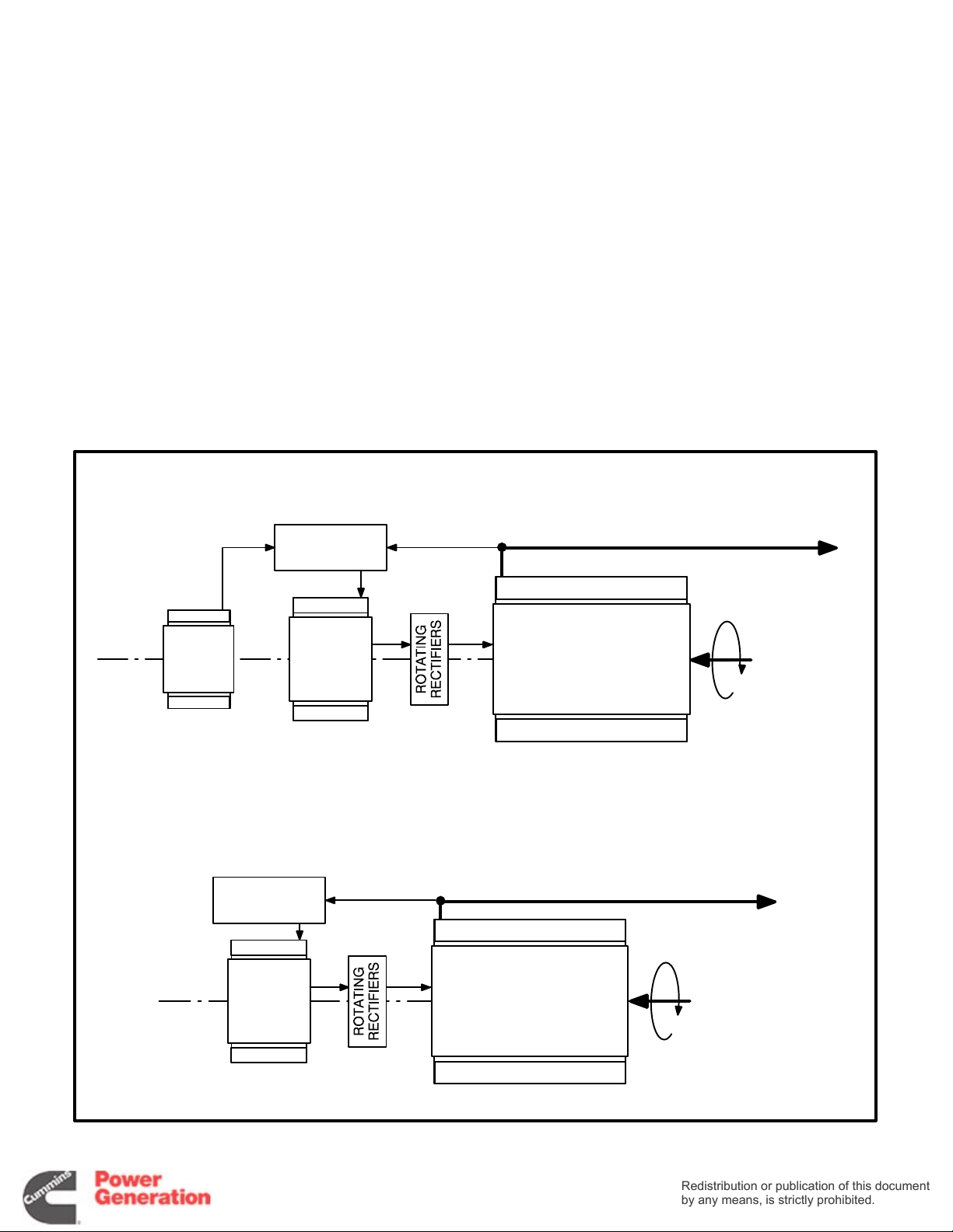
PRINCIPLE OF GENERATOR OPERATION
Redistribution or publication of this document
by any means, is strictly prohibited.
Redistribution or publication of this document
by any means, is strictly prohibited.
1. The generator field (main rotor) is rotated by
the engine to induce output current (AC) in the
main stator windings.
2. Generator output current is proportional to field
strength, which is varied to match the load.
Output voltage and frequency are held
constant by the voltage regulator and engine
governor, respectively.
3. Generator field strength is proportional to field
current, which is supplied by the exciter.
4. The exciter field (stator) induces current in the
exciter rotor windings. A full wave rectifier
bridge (rotating rectifiers) mounted on the exciter rotor converts exciter output (3-phase AC)
to DC. The exciter rotor is mounted on the main
rotor shaft.
PMG-EXCITED GENERATORS
5. Exciter output current is proportional to exciter
field current.
6. The automatic voltage regulator (AVR) regulates exciter field current by comparing generator output voltage and frequency with reference values.
7. PMG-Excited Generators. Exciter field current is supplied by a PMG (permanent magnet)
exciter through the voltage regulator . The PMG
consists of a stator and a permanent magnet
rotor mounted on the end of the main rotor
shaft.
8. Self-Excited Generators. Exciter field current
is supplied by the generator stator through the
voltage regulator. Residual field magnetism initiates “self-excitation” during startups.
PMG
ROTOR
AND
STATOR
AVR
EXCITER
ROTOR
AND
STATOR
AVR
EXCITER
ROTOR
AND
STATOR
ELECTRICAL POWER OUTPUT
MAIN STATOR
MAIN ROTOR
SELF-EXCITED GENERATORS
ELECTRICAL POWER OUTPUT
MAIN STATOR
MAIN ROTOR
ROTATING
MECHANICAL
POWER
INPUT
ROTATING
MECHANICAL
POWER
INPUT
FIGURE 2-6. SCHEMATIC OF GENERATOR OPERATION
2-7

Redistribution or publication of this document
by any means, is strictly prohibited.
Redistribution or publication of this document
by any means, is strictly prohibited.
2-8
3. Engine Control
Redistribution or publication of this document
by any means, is strictly prohibited.
Redistribution or publication of this document
by any means, is strictly prohibited.
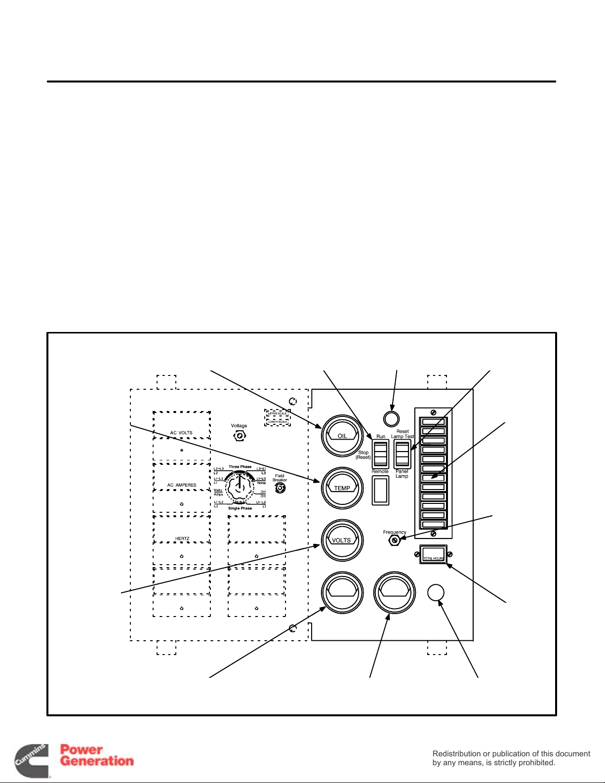
CONTROL PANEL
The control box is mounted on top of the generator,
facing the rear. Figure 3-1 shows the components
on the engine control panel.
STANDARD CONTROL PANEL
COMPONENTS
Run / Stop / Remote Switch (S12) The switch is
pushed to t h e Run position to start and run the generator set and the Stop position to stop the set. The
Remote position allows a remote controller to automatically run the set. The switch must be in the Stop
position when the reset switch (described next) is
used to restore generator set operation following a
fault shutdown.
OIL PRESSURE
GAUGE
COOLANT
TEMPERATURE
GAUGE
RUN/STOP/REMOTE
Reset / Lamp Test / Panel Lamp Switch (S11)
switch is pushed to the Reset position (momentary
contact) to reset the engine control to restore operation following a fault shutdown. The Run / Stop / Re-
mote switch must be in the Stop position for reset to
occur. The Lamp Test position (momentary con-
tact) lights all the fault indicator lamps. Replace
lamps that do not light. The Panel Lamp position
lights the panel illumination lamp.
Oil Pressure Gauge (M11)
The oil pressure gauge
indicates engine oil pressure.
Coolant Temperature Gauge (M12)
The coolant
temperature gauge indicates engine coolant temperature.
RESET/LAMP TEST/
PANEL LIGHT SWITCH
INDICATOR
SWITCH
PANEL
LIGHT
LAMPS
The
DC
VOLTMETER
OIL TEMPERATURE
GAUGE
SPEED
ADJUSTING
RHEOSTAT
HOUR
METER
TACHOMETER EMERGENCY STOP
BUTTON
FIGURE 3-1. ENGINE CONTROL PANEL
3-1
DC Voltmeter (M13) The DC voltmeter indicates
Redistribution or publication of this document
by any means, is strictly prohibited.
Redistribution or publication of this document
by any means, is strictly prohibited.
voltage across the battery terminals during operation.
Hour Meter (M14)
The hour meter indicates the accumulated number of hours the set has run. It cannot be reset.
Panel Lamp (DS1 1) The panel lamp illuminates the
control panel.
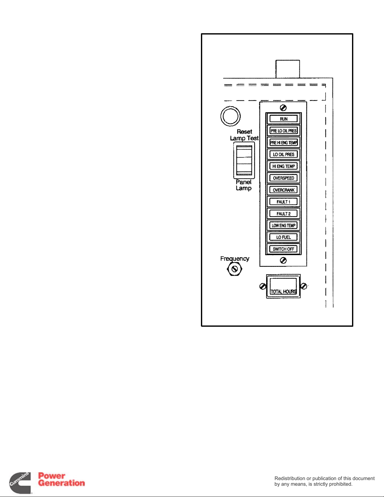
Detector-7 Fault and Status Indicator Lamps
(A12)
• Run (Green) This lamp indicates that the gen-
erator set is running and that the starter has
been disconnected.
• Pre Low Oil Pressure (Yellow) This lamp indi-
cates that engine oil pressure is abnormally low
(less than 20 psi).
• Low Oil Pressure (Red) This lamp indicates
that the engine shut down because of excessively low engine oil pressure (less than
14 psi).
• Pre High Engine Temperature (Yellow) This
lamp indicates that engine coolant temperature is abnormally high (greater than 220
° F).
• High Engine Temperature (Red) This lamp
indicates that the engine shut down because of
excessively high engine coolant temperature
(greater than 230
° F).
• Overcrank (Red) This lamp indicates that the
engine shut down because it did not start during the timed cranking period (approximately
75 seconds, including two rest periods).
• Overspeed (Red) This lamp indicates that the
engine shut down because of overspeed.
539−0741c2
OPTIONAL CONTROL PANEL
COMPONENTS
Oil Temperature Gauge (M15) The oil temperature
gauge indicates engine oil temperature.
Tachometer (M16) The tachometer indicates en-
gine speed in RPM.
Speed Adjusting Rheostat The speed adjusting
rheostat is used to adjust engine speed from the
control panel (an option with the optional electric
governor).
FIGURE 3-2. DETECTOR-12 INDICATOR LAMPS
3-2
Emergency Stop Button (S14) The emergency
Redistribution or publication of this document
by any means, is strictly prohibited.
Redistribution or publication of this document
by any means, is strictly prohibited.
stop button is a red, push-in switch used to stop the
engine. The button lights up when it is pushed in.
The button has to be pulled out and the engine control reset to restore operation.
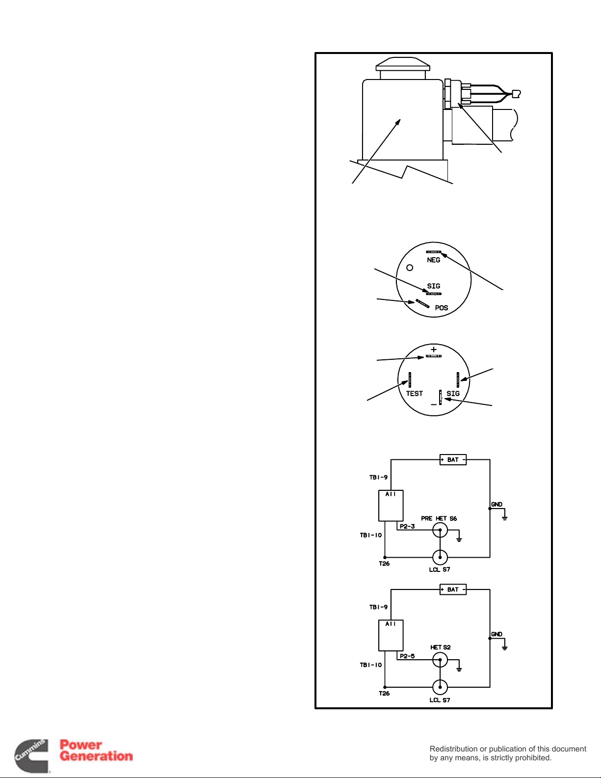
Low Coolant Level Cutout Switch (S7) When
coolant level in the radiator top tank falls below the
switch sensor, the switch closes the circuit to
ground. This switch may be connected in parallel
with the high engine temperature cutout switch to
shut down the engine and light the High Engine
Temperature lamp or in parallel with the pre-high
engine temperature switch to light the Pre High En-
gine Temperature light only.
Detector-12 Fault and Status Indicator Lamps
(A12) The Detector-12 control panel has the five fol-
lowing indicator lamps in addition to the standard
seven.
RADIATOR
TOP TANK
——— SWITCH TERMINALS ——-
SWITCH
S2 OR S6
SWITCHED
B+
(T26)
LOW
COOLANT
LEVEL
SWITCH
(S7)
ENGINE
GROUND
• Low Engine Temperature (Yellow) This lamp
indicates that engine temperature is less than
° F, and the possibility that the engine might
70
not start.
• Low Fuel (Yellow) This lamp indicates that the
fuel level in the supply tank has dropped to less
than the reserve necessary to run the set at full
load for the prescribed number of hours. The
customer has to make connections to use this
lamp.
• Fault 1 (Red) This lamp indicates that the en-
gine shut down because of a system fault. The
customer has to make connections to use this
lamp. The lamp is a part of a 10 second time
delay shutdown circuit. The customer can
make reconnections for non-timed shutdown.
See Engine Control Monitor (ECM).
• Fault 2 (Red) This lamp indicates that the en-
gine shut down because of a system fault. The
customer has to make connections to use this
lamp. The lamp is part of a non-time delay shutdown circuit. The customer can make reconnections for 10 second time delay shutdown.
See Engine Control Monitor (ECM).
SWITCHED
B+
(T26)
NOT
USED
———— SCHEMATICS ————
—— OR ——
ECM
ECM
SWITCH
S2 OR S6
ENGINE
GROUND
WARNING
ONLY
SHUTDOWN
• Switch-off (Flashing Red) This lamp indi-
cates that the Run / Stop / Remote switch is in
the Stop position, which prevents remote, automatic operation.
FIGURE 3-3. LOW COOLANT LEVEL SWITCH
3-3
VOLTAGE
Redistribution or publication of this document
by any means, is strictly prohibited.
Redistribution or publication of this document
by any means, is strictly prohibited.
REGULATOR
VR21
ENGINE
CONTROL
MONITOR A11
TIME DELAY
START/STOP
MODULE A15
TERMINAL BOARD
TB21
RUN RELAYS K11
(NOT SHOWN − MOUNTED ON
A BRACKET IN FRONT OF A11)
FIGURE 3-4. ARRANGEMENT OF COMPONENTS INSIDE THE CONTROL BOX
CONTROL BOX INTERIOR
Figure 3-4 shows the arrangement of components
inside the control box, including the engine control
monitor and some of the auxiliary components under following headings.
ENGINE CONTROL MONITOR (A11)
The heart of the engine control system is the engine
control monitor (ECM). It is a printed circuit board
assembly mounted on the back wall of the control
box. It starts and stops the engine in response to the
control panel switches, engine sensors and remote
control signals. Figure 3-5 shows the newer ECM
board used in current production and as a direct replacement for older boards. The boards are distinquishable from each other in that the newer boards
have automotive-type fuses and the older boards
have cartridge-type fuses.
Terminals and Connectors
See Pages 9-7 through 9-10 for the appropriate
connection and schematic drawings for the DC control system. See Page 9-16 for typical customer
connections at terminal boards TB1 and TB2 on the
ECM and page 9-17 if the set is also equipped with
the auxiliary relay board.
OVERSPEED
MODULE
ALARM RELAY MODULES
A13 AND A14
ES1561s−
1
Fuses
The ECM has five replaceable fuses to protect it
from overloads and groundfaults. They are:
F1 Starter solenoid circuit, 20 amps
F2 Fuel solenoid (switched B+) circuits, 20 amps
F3 Continuous B+ out to remote circuits, 15 amps
F4 ECM circuits, 5 amps
F5 Engine gauge circuits, 5 amps.
Function Selection Jumpers
Newer ECM boards have six selection jumpers that
can be repositioned to provide the following timed
or non-timed warnings or timed or non-timed shutdowns with warnings:
W1 Jumper Position (jumper W8 must be in the B
position):
A Non-timed warning under FLT 2 condi-
tions.
B Non-timed shutdown and warning under
FLT 2 conditions.
C Timed warning under FLT 2 conditions.
D Timed shutdown and warning under FLT 2
conditions.
3-4
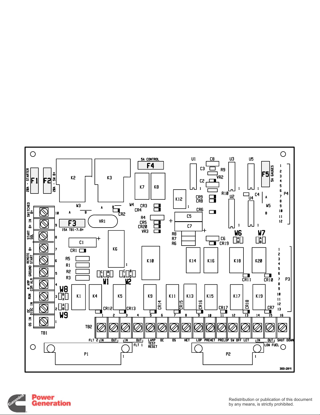
W2 Jumper Position (jumper W9 must be in the B
Redistribution or publication of this document
by any means, is strictly prohibited.
Redistribution or publication of this document
by any means, is strictly prohibited.
position):
A Non-timed warning under FLT 1 condi-
tions.
B Non-timed shutdown and warning under
FLT 1 conditions.
C Timed warning under FLT 1 conditions.
D Timed shutdown and warning under FLT 1
conditions.
W6 Jumper Position:
A Warning under Pre-High Engine Tem-
perature conditions.
B Shutdown and warning under Pre-High
Engine Temperature conditions.
W7 Jumper Position:
A Warning under Pre-Low Oil Pressure
conditions.
B Shutdown and warning under Pre-Low
Oil Pressure conditions.
W8 Jumper Position:
A Warning while running or during standby
under FLT 2 conditions.
B Allows selection of functions with W1
jumper.
W9 Jumper Position:
A Warning while running or during standby
under FLT 1 conditions.
B Allows selection of functions with W2
jumper.
87654321 654321
FIGURE 3-5. ENGINE CONTROL MONITOR FUSES AND FUNCTION SELECTION JUMPERS
3-5
ENGINE SENSORS
Redistribution or publication of this document
by any means, is strictly prohibited.
Redistribution or publication of this document
by any means, is strictly prohibited.
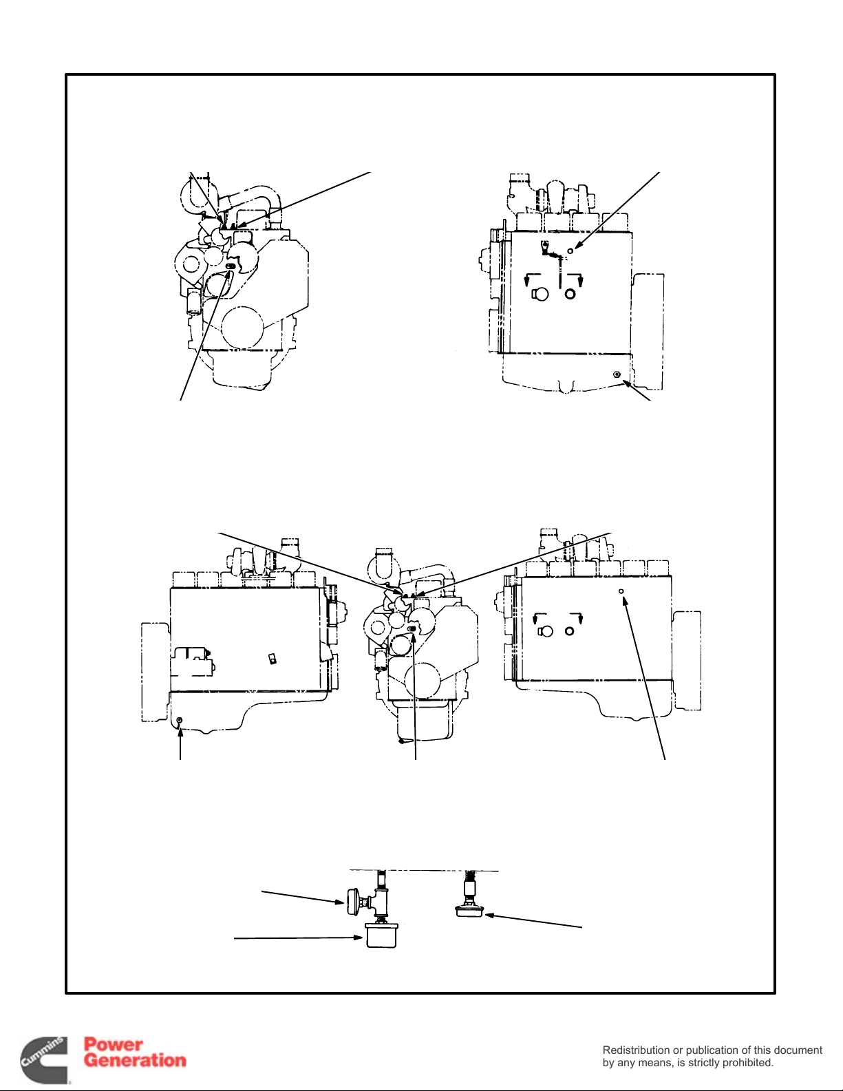
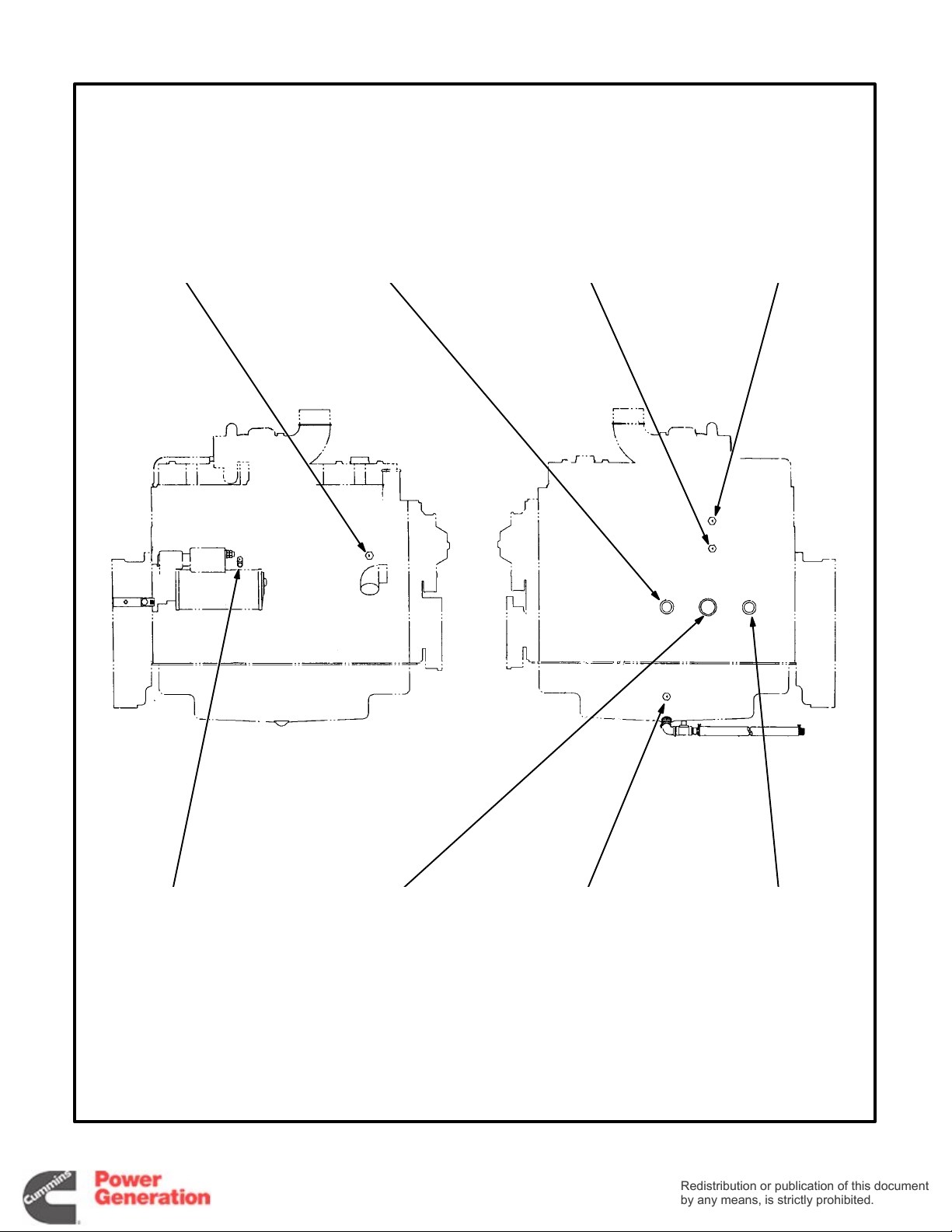
Figures 3-6, 3-7, 3-8 and 3-9 show the locations of
the gauge senders and the coolant temperature
and oil pressure sensing switches to which the ECM
responds. The switches function by closing the fault
or warning circuit to the engine chassis ground (battery negative [-]).
POSITIVE BATTERY
CABLE CONNECTION
POINT (B1)
PRE-LOW OIL
PRESSURE
SENSOR S5
PRE-HIGH ENGINE
TEMPERATURE
SENSOR S6
HIGH ENGINE
TEMPERATURE
SENSOR S2
COOLANT
TEMPERATURE
SENDER E2
GND
AND T26
(SWITCHED B+)
CONNECTION POINT
FIGURE 3-6. ENGINE SENSOR LOCATIONS (FOUR CYLINDER B-SERIES ENGINES)—BEGINNING SPEC H
NEGATIVE
BATTERY CABLE
OIL
PRESSURE
SENDER E1
LOW ENGINE
TEMPERATURE
SENSOR S4
3-6
TEMPERATURE
SENDER E4
LOW OIL
PRESSURE
SENSOR S1
OIL
100-3148, REV
C
POSITIVE BATTERY
Redistribution or publication of this document
by any means, is strictly prohibited.
Redistribution or publication of this document
by any means, is strictly prohibited.
CABLE CONNECTION
POINT (B1)
PRE-LOW OIL
PRESSURE
SENSOR S5
PRE-HIGH ENGINE
TEMPERATURE
SENSOR S6
HIGH ENGINE
TEMPERATURE
SENSOR S2
COOLANT
TEMPERATURE
SENDER E2
OIL
TEMPERATURE
SENDER E4
FIGURE 3-7. ENGINE SENSOR LOCATIONS (SIX CYLINDER B-SERIES ENGINES)—BEGINNING SPEC H
(SWITCHED B+)
OIL
PRESSURE
SENDER E1
GND
AND T26
NEGATIVE
BATTERY CABLE
CONNECTION POINT
3-7
LOW ENGINE
TEMPERATURE
SENSOR S4
LOW OIL
PRESSURE
SENSOR S1
100-3141, REV
D
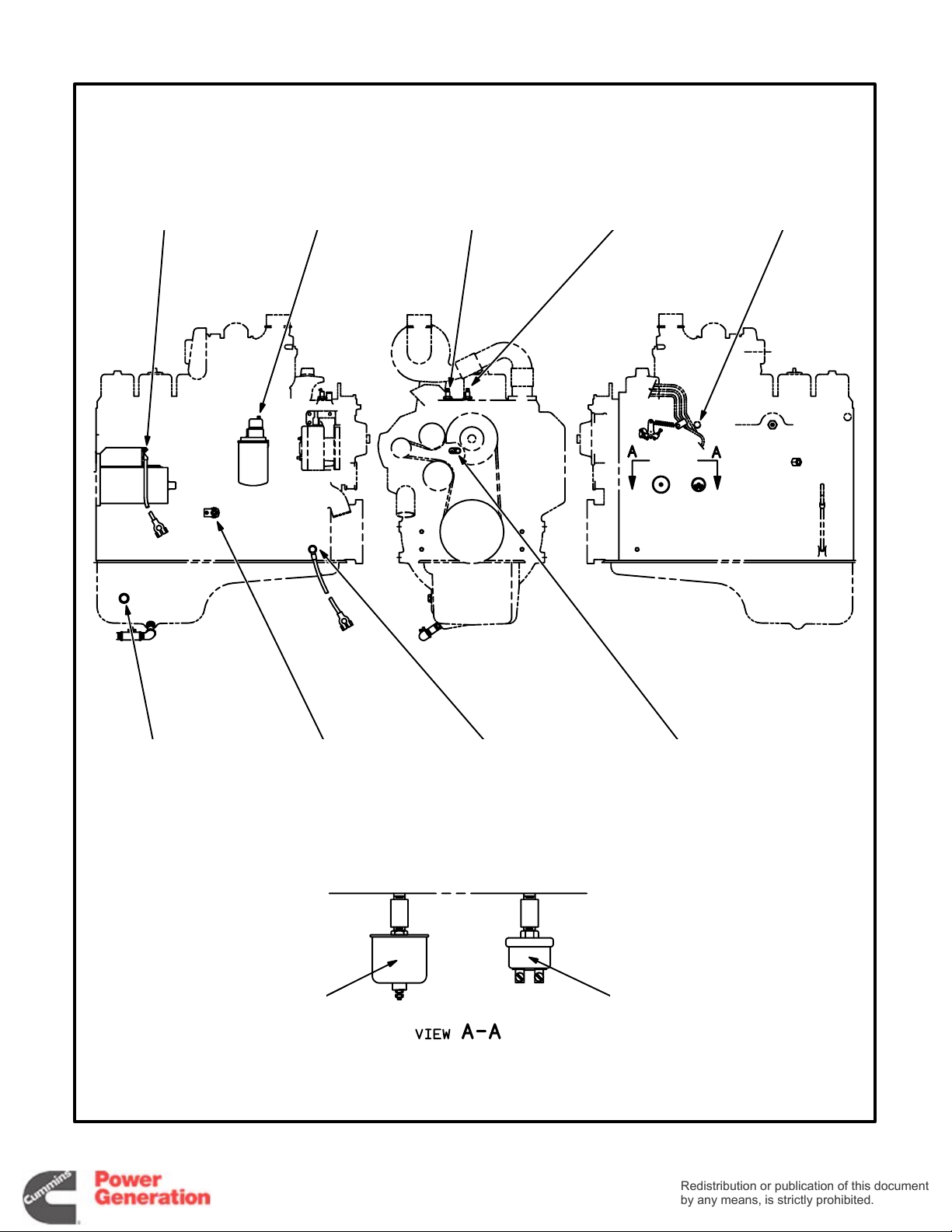
— FOUR CYLINDER ENGINES —
Redistribution or publication of this document
by any means, is strictly prohibited.
Redistribution or publication of this document
by any means, is strictly prohibited.
HIGH ENGINE TEMPERATURE
SENSOR (S2)
LOW ENGINE TEMPERATURE
SENSOR (S4)
HIGH ENGINE TEMPERATURE
SENSOR (S2)
PRE-HIGH ENGINE
TEMPERATURE SENSOR (S6)
— SIX CYLINDER ENGINES —
COOLANT TEMPERATURE
SENDER (E2)
AA
OIL TEMPERATURE
SENDER (E4)
PRE-HIGH ENGINE
TEMPERATURE SENSOR (S6)
OIL TEMPERATURE
SENDER (E4)
LOW OIL PRESSURE
SENSOR (S1)
OIL PRESSURE
SENDER (E1)
LOW ENGINE TEMPERATURE
SENSOR (S4)
— VIEW A-A —
AA
COOLANT TEMPERATURE
PRE-LOW OIL PRESSURE
SENDER (E2)
SENSOR (S5)
M1695
M1695−1
FIGURE 3-8. ENGINE SENSOR LOCATIONS (B-SERIES ENGINES)—PRIOR TO SPEC H
3-8
HIGH ENGINE
Redistribution or publication of this document
by any means, is strictly prohibited.
Redistribution or publication of this document
by any means, is strictly prohibited.
TEMPERATURE
SENSOR (S2)
PRE-LOW OIL
PRESSURE
SENSOR (S5)
PRE-HIGH ENGINE
TEMPERATURE
SENSOR (S6)
COOLANT
TEMPERATURE
SENDER (E2)
LOW ENGINE
TEMPERATURE
SENSOR (S4)
FIGURE 3-9. ENGINE SENSOR LOCATIONS (C-SERIES ENGINES)
OIL
PRESSURE
SENDER (E1)
3-9
OIL
TEMPERATURE
SENDER (E4)
LOW OIL
PRESSURE
SENSOR (S1)
M1720
AUXILIARY CONTROL COMPONENTS
Redistribution or publication of this document
by any means, is strictly prohibited.
Redistribution or publication of this document
by any means, is strictly prohibited.
The set might be equipped with one or more of the
following components.
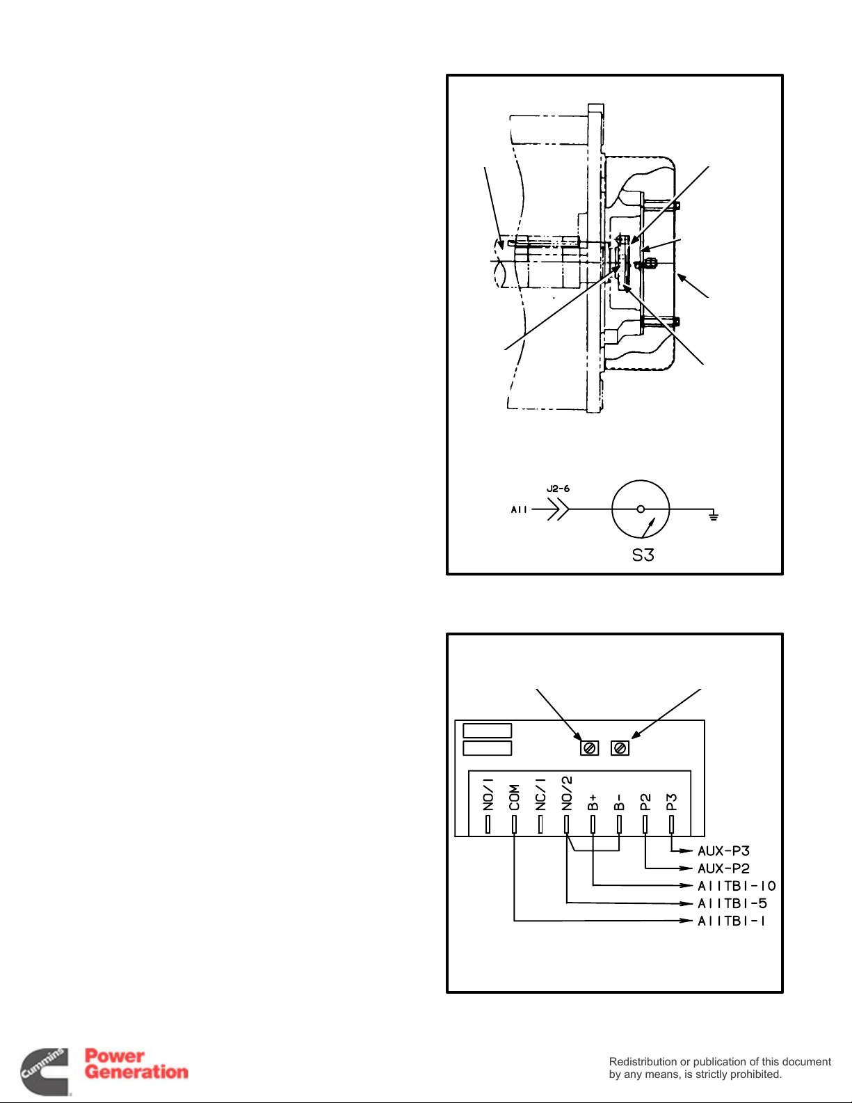
Mechanical Overspeed Switch (Standard)
The mechanical overspeed switch is bolted to the
end of the generator rotor shaft.
1. Check overspeed cutout RPM and turn the adjustment screw, i f necessary, so that shutdown
occurs within the following RPM ranges:
60 Hz Sets 2000 to 2200 RPM. . . . . . . .
50 Hz Sets 1800 to 2100 RPM. . . . . . . .
2. Replace the switch if the cutout speed adjustment results in an air gap between the magnet
and the fly arm of less than 0.005 inches (0.13
mm).
3. Torque the center rotor bolt to 40 ft-lbs (54 Nm)
when replacing the switch.
MAIN
ROTOR
SHAFT
ROTOR
CENTER
BOLT
CUTOUT
SWITCH
ASSEMBLY
SWITCH
CONTACT
BRACKET
SWITCH
COVER
CUTOUT RPM
ADJUSTMENT
SCREW
Es1860s
—SCHEMATIC—
Electronic Overspeed Module (Optional)
PMG-excited generators are equipped with an electronic overspeed module in the control box. The
module senses PMG output frequency to determine
generator speed (frequency). Adjust the overspeed
pot to cut out at 1800 to 1900 RPM for 50 Hz sets
and 2100 to 2200 RPM for 60 Hz sets. Do not adjust
the cranking pot.
FIGURE 3-10. MECHANICAL OVERSPEED SWITCH
FOR FACTORY
ADJUSTMENTS
ONLY
* − AUXILIARY TERMINAL BLOCK
OVERSPEED
ADJUSTMENT
POT
*
*
612-6488
FIGURE 3-11. ELECTRONIC OVERSPEED MODULE
3-10
Run Relays (K11)
Redistribution or publication of this document
by any means, is strictly prohibited.
Redistribution or publication of this document
by any means, is strictly prohibited.
The set can be equipped with one to three 3-pole,
double-throw relays to control auxiliary equipment
such as fans, pumps, and motorized air dampers.
The relays are mounted on a standoff bracket in
front of the ECM.
A11
TB1
TB1
10
K11
B
A
5
The contacts are rated:
• 10 amps at 28 VDC or 120 VAC, 80% PF
• 6 amps at 240 VAC, 80% PF
• 3 amps at 480 VAC, 80% PF
The set might instead be equipped with an auxiliary
relay board. If so, see Auxiliary Relay Board (ARB).
Alarm Relay Modules (A13 and A14)
The set can be equipped with relay modules to interface with a remote annunciator that is powered
independently of the control circuit of the set. Sets
with Detector-7 need module A13 and sets with Detector-12, modules A13 and A14.
These are all normally open contacts and they are
rated:
• 15 amps at 250 VAC
• 15 amps at 30 VDC
K11
K11
K11
FIGURE 3-12. RUN RELAYS
A14
TB1
FAULT#1
FAULT#2
LET
LOW FUEL
SWITCH
OFF
1
7
4
5
3
9
2
8
6
CUSTOMER
CONNECTIONS
TB2
A11-TB2-4
A11-TB2-2
A11-TB2-13
A11-TB2-15
A11-TB2-12
A13-TB2-8
The set might instead be equipped with an auxiliary
relay board. If so, see Auxiliary Relay Board (ARB).
3-11
A13
TB1
RUN
PRE -LOP
PRE-HET
LOP
HET
OS
OC
TB2
A11-TB1-3
A11-TB2-11
A11-TB2-10
A11-TB2-9
A11-TB2-8
A11-TB2-7
A11-TB2-6
A11-TB1-7
A14-TB2-6
(12 LIGHT)
FIGURE 3-13. ALARM RELAY MODULES

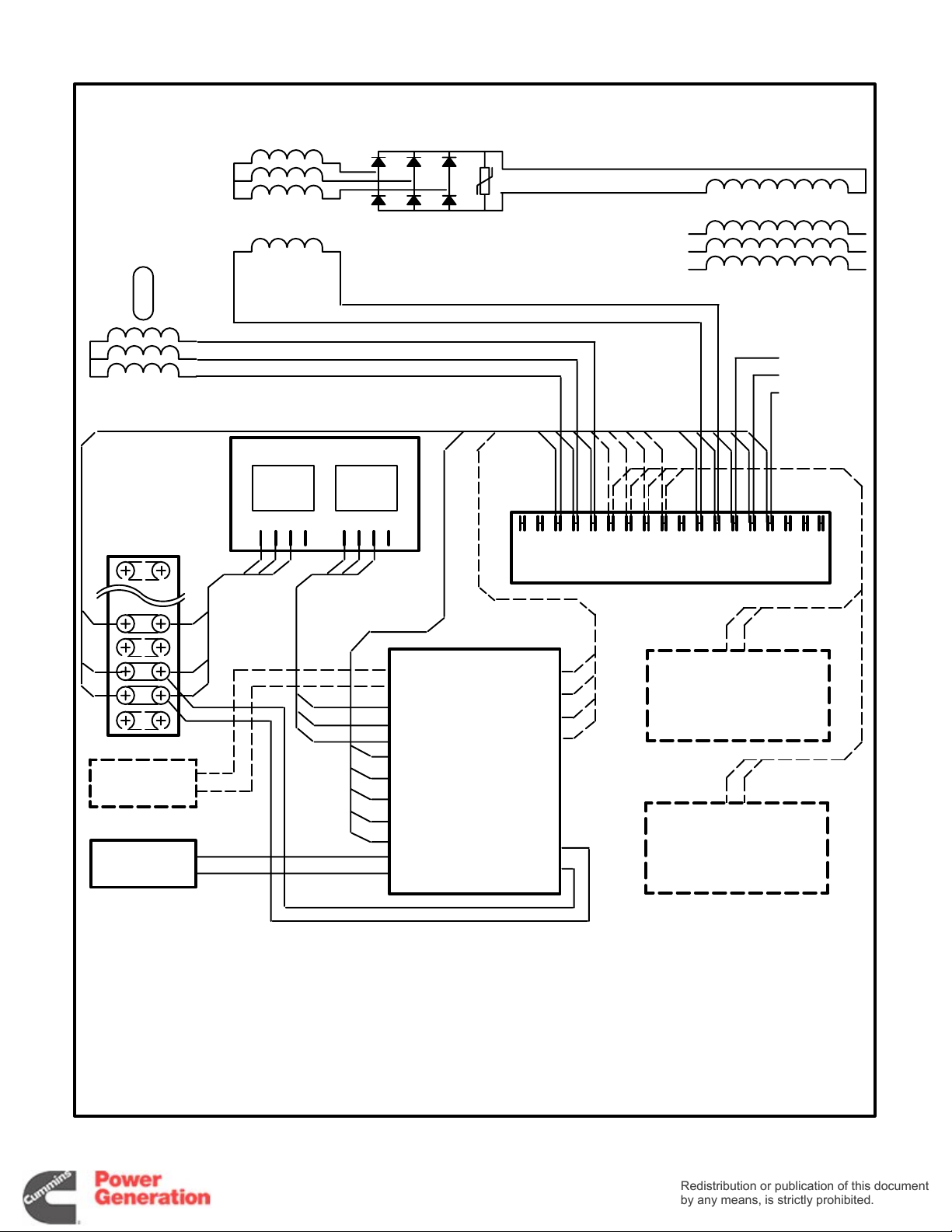
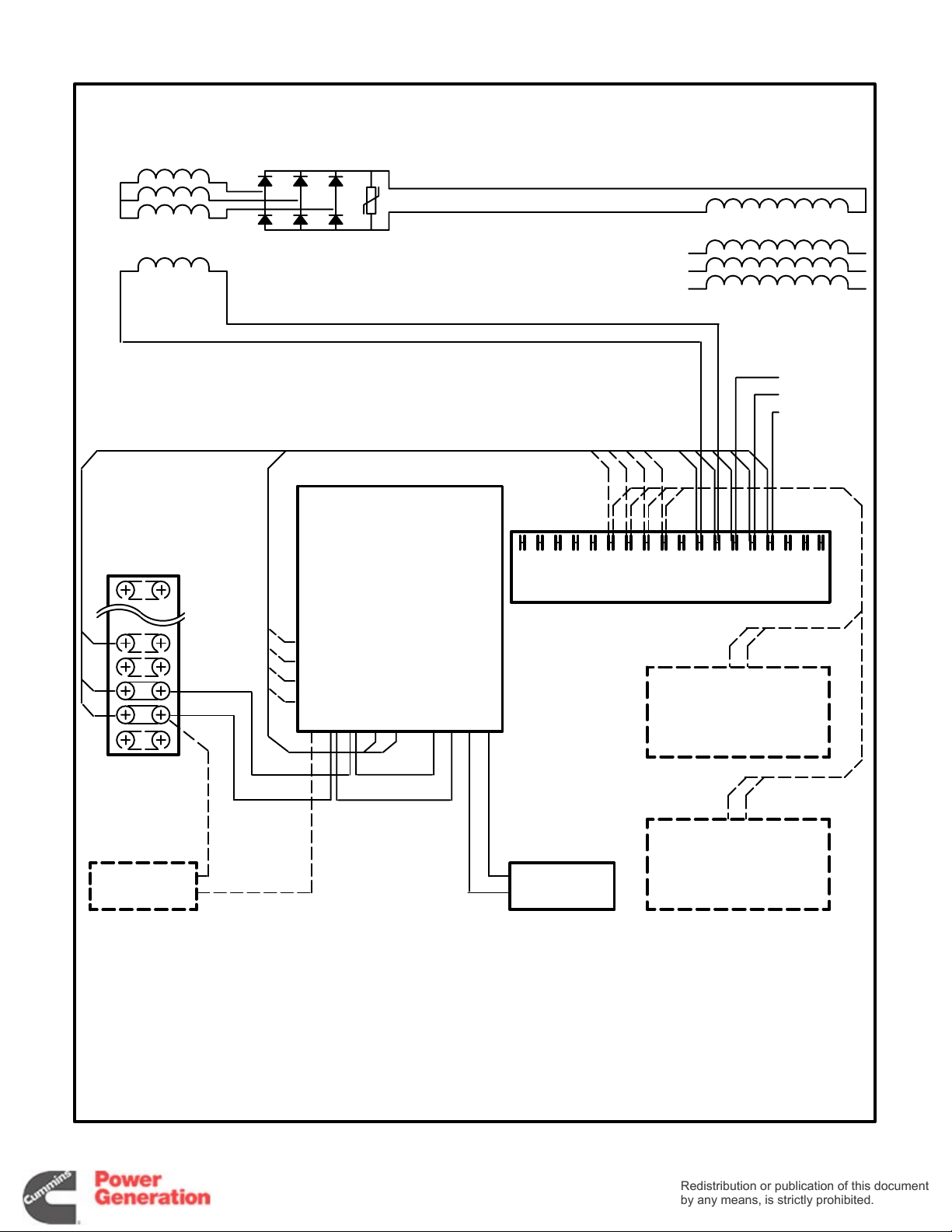
Auxiliary Relay Board (ARB)
Redistribution or publication of this document
by any means, is strictly prohibited.
Redistribution or publication of this document
by any means, is strictly prohibited.
The following describes the design/functional criteria for the auxiliary relay board (ARB) with a Detector-7 or -12 Genset control. The board is mounted
directly on top of the ECM using standoffs and has
access holes for the fuses located on the ECM.
There are two versions of the ARB; with and without
the set of 12 Fault relays (Figure 3-14). Page 9-17 is
a detailed connection diagram for the ARB.
The set might instead be equipped with separate
run and alarm relay modules. If so, see Run Relay
(K11) and Alarm Relay Modules (A13 and A14).
Terminal Blocks:
• TB1 − ARB TB1 and ECM TB1 are identically
numbered and provide the same remote control connection points. Note that additional terminals are provided for terminals 5, 7, and 10 of
ARB TB1.
• TB2 through TB5 − Connection points for re-
lays K1 through K3. TB2 provides the N/O and
N/C connections (three form ‘C’ contacts for
each relay). TB3 through TB5 provide the common connection points (TB3 for K1, TB4 for K2
and TB5 for K3).
• TB6 and TB7 − Connection points for fault re-
lays K4 through K15. Three terminals are provided for each relay, which are labeled COM,
N/C, N/O.
Plug-In Relays (K1, K2, K3):
equipped with one to three 3-pole, double-throw relays. These relays (K1, K2, K3) are field changeable
plug-in relays for easy field addition and replacement.
Each relay can be operated as a RUN, COMMON
ALARM, or ISOLATED COIL with the changing of a
jumper.
The relay contact ratings are:
The ARB can be
• 10 amps at 28 VDC or 120 VAC, 80% PF
• 6 amps at 240 VAC, 80% PF
• 3 amps at 480 VAC, 80% PF
Jumper Positions for Plug-In Relays:
W1, W2 and W3 perform the same functions for
Jumpers
their respective relays, W1 for relay K1, W2 for relay
K2, and W3 for relay K3. They can be located in any
of 3 positions (A, B, C) independently of each other.
• Jumper Position A (Run) − The relay oper-
ates as a Run relay, energizing when SW B+ is
applied from the ECM.
• Jumper Position B (Common Alarm) − The
relay operates as a Common Alarm relay. The
relay energizes any time there is an engine
shutdown. This signal is provided from the
ECM.
• Jumper Position C (Isolated) − The relay op-
erates as an Isolated relay. The relay coil is energized by a customer applied B+ signal
through the terminal block; TB3-1 for relay K1,
TB4-1 for relay K2, and TB5-1 for relay K3.
Jumpers W11, W12, and W13 perform the same
functions for their respective relays; W11 for relay
K1, W12 for relay K2, and W13 for relay K3. They
can be located in two different positions (A, B) independently of one another.
• Jumper Position A − The relay operates iso-
lated from the board. The customer provides
the circuit completion through terminal block;
TB3 for relay K1, TB4-5 for relay K2, and TB5-5
for relay K3. The customer can operate the
relay with switched ground logic or use this
relay in the middle of more complex logic circuits if needed.
• Jumper Position B − The relays operate with
the coils connected to ground through the
board connections. The coil will require a B+
signal to energize with the jumper in this position.
Fault Relays (K4 through K15):
relay modules are used to operate a remote alarm
annunciator that has an independent power source.
This allows the use of either AC or DC for alarm
drives. The relays are energized through the latching relays on the ECM and provided N/O and N/C
contacts for each external alarm connection.
The 12 relays with form ‘C’ contacts are rated:
These optional
• 10 Amp, 120 VAC
• 10 Amp. 30 VDC
3-12
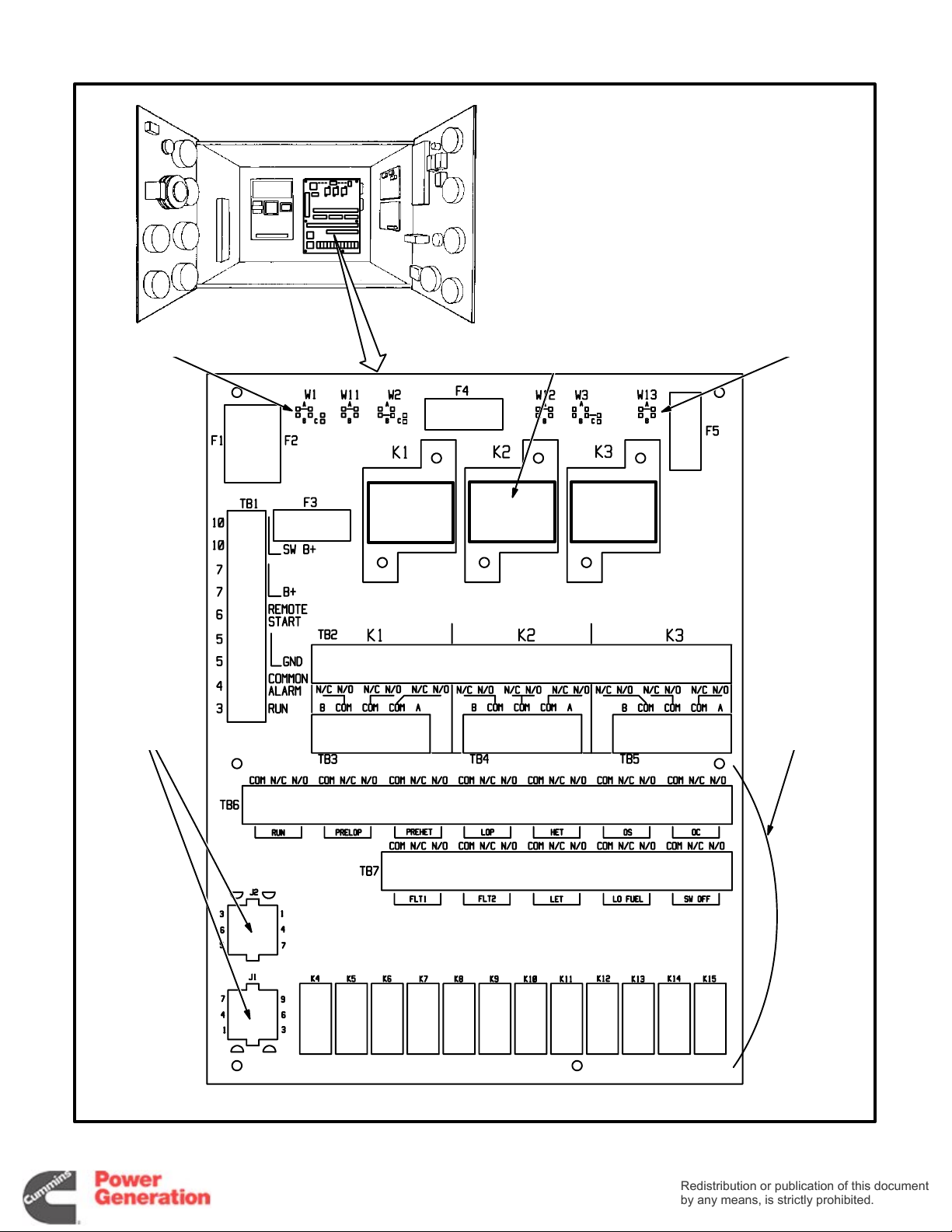
JUMPERS JUMPERS
Redistribution or publication of this document
by any means, is strictly prohibited.
Redistribution or publication of this document
by any means, is strictly prohibited.
RUN RELAY
MODULE(S)
K1 K2 K3
J1, J2 WIRE
HARNESS PLUG
CONNECTIONS
FROM ECM
TB6, TB7 AND
RELAYS K4
THROUGH K15
ARE OPTIONAL
300−4111c
FIGURE 3-14. AUXILIARY RELAY BOARD (ARB)
3-13

Over / Under Voltage Module (A17)
Redistribution or publication of this document
by any means, is strictly prohibited.
Redistribution or publication of this document
by any means, is strictly prohibited.
The set can be equipped with an adjustable voltage-sensitive relay usually connected into the Fault
1 circuit (Detector-12 controls only) to shut down
the set when the output voltage is over or under
nominal voltage by the preselected percentage
(typically 10 percent over and under).
With the module is an adjustable time delay relay
(K17) to prevent nuisance tripping. An adjustment
of 25 percent is equivalent to about 2.5 seconds
delay.
Recalibrate the module as follows before installing
it on 139/240 VAC or 277/480 VAC sets.
1. Remove the two screws that secure the top to
the case of the module and withdraw the top
assembly.
2. Adjust the SET pot for the UNDER setpoint on
the face of the top assembly to 75 percent.
3. Apply single-phase, 60 Hertz, 104.25 VAC
across terminals L and N.
4. Adjust pot R25 on the PC board until the relay
trips (de-energizes).
5. Adjust the SET pot for the OVER setpoint on
the face of the top assembly to 125 percent.
6. Apply single-phase, 60 Hertz, 173.75 VAC
across terminals L and N.
7. Adjust pot R26 on the PC board until the relay
trips (energizes).
8. Repeat the above steps until no adjustments
are necessary.
9. Reassemble the module.
10. On the module nameplate mark out the factory
calibration value for monitored voltage (120 V)
and write in 139 V.
*
*
**
* CONNECTED TO TB11-45 WHEN GENERA-
TOR IS PARALLELED.
** CONNECTED TO GENERATOR LEAD LO
WHEN THE GENERATOR IS CONNECTED
FOR SINGLE PHASE.
FIGURE 3-15. OVER / UNDER VOLTAGE
MODULE
Over / Under Frequency Module (A19)
The set can be equipped with an adjustable frequency-sensitive relay to shut down the set when
the output frequency (Hz) is over or under nominal
frequency by the preselected amount. It is usually
connected into the Fault 2 circuit (Detector-12 con-
trols only) if the over / under voltage module is also
provided. Set points are typically 5 Hertz over and
under nominal frequency (50 or 60 Hertz) and reset
points 3 Hertz over and under.
3-14
300-314
FIGURE 3-16. OVER / UNDER FREQUENCY
MODULE
1
 Loading...