

Page 1

Caution: This document contains mixed page sizes (8.5 x 11 or 11 x
Redistribution or publication of this document
by any means, is strictly prohibited.
Redistribution or publication of this document
by any means, is strictly prohibited.
17), which may affect printing. Please adjust your printer settings
according to the size of each page you wish to print.
Page 2
Service Manual
Redistribution or publication of this document
by any means, is strictly prohibited.
Redistribution or publication of this document
by any means, is strictly prohibited.
Detector Control
Generator Sets
Printed in U.S.A.
Models
DGBA, DGBB, DGBC, DGCA, DGCB, DGDA, DGDB
DGEA, DGFA, DGFB
QSGBA, QSGCA, QSGCB, QSDA, QSDB, QSEA, QSFA
4B3.9, 4BT3.9, 6BT5.9, 6CT8.3, 6CTA8.3
960-0505 4-2001
Page 3

Table of Contents
Redistribution or publication of this document
by any means, is strictly prohibited.
Redistribution or publication of this document
by any means, is strictly prohibited.
SECTION TITLE PAGE
SAFETY PRECAUTIONS iii. . . . . . . . . . . . . . . . . . . . . . . . . . . . . . . . . . . . . . . . . . .
1 INTRODUCTION 1-1. . . . . . . . . . . . . . . . . . . . . . . . . . . . . . . . . . . . . . . . . . . . . . . . . .
About This Manual 1-1. . . . . . . . . . . . . . . . . . . . . . . . . . . . . . . . . . . . . . . . . . . . . . .
Test Equipment 1-1. . . . . . . . . . . . . . . . . . . . . . . . . . . . . . . . . . . . . . . . . . . . . . . . . .
2 AC CONTROL 2-1. . . . . . . . . . . . . . . . . . . . . . . . . . . . . . . . . . . . . . . . . . . . . . . . . . . .
General 2-1. . . . . . . . . . . . . . . . . . . . . . . . . . . . . . . . . . . . . . . . . . . . . . . . . . . . . . . .
Standard Control Panel Components 2-1. . . . . . . . . . . . . . . . . . . . . . . . . . . . . . .
Optional Control Panel Components 2-1. . . . . . . . . . . . . . . . . . . . . . . . . . . . . . .
Automatic Voltage Regulator (AVR) Adjustments 2-2. . . . . . . . . . . . . . . . . . . . .
Principle Of Generator Operation 2-7. . . . . . . . . . . . . . . . . . . . . . . . . . . . . . . . . .
3 ENGINE CONTROL 3-1. . . . . . . . . . . . . . . . . . . . . . . . . . . . . . . . . . . . . . . . . . . . . . .
Control Panel 3-1. . . . . . . . . . . . . . . . . . . . . . . . . . . . . . . . . . . . . . . . . . . . . . . . . . .
Standard Control Panel Components 3-1. . . . . . . . . . . . . . . . . . . . . . . . . . . . . . .
Optional Control Panel Components 3-2. . . . . . . . . . . . . . . . . . . . . . . . . . . . . . .
Control Box Interior 3-3. . . . . . . . . . . . . . . . . . . . . . . . . . . . . . . . . . . . . . . . . . . . . .
Engine Control Monitor (A11) 3-4. . . . . . . . . . . . . . . . . . . . . . . . . . . . . . . . . . . . . .
Engine Sensors 3-6. . . . . . . . . . . . . . . . . . . . . . . . . . . . . . . . . . . . . . . . . . . . . . . . .
Auxiliary Control Components 3-10. . . . . . . . . . . . . . . . . . . . . . . . . . . . . . . . . . . .
Sequence Of Operation 3-16. . . . . . . . . . . . . . . . . . . . . . . . . . . . . . . . . . . . . . . . .
4 TROUBLESHOOTING 4-1. . . . . . . . . . . . . . . . . . . . . . . . . . . . . . . . . . . . . . . . . . . . .
The Engine Does Not Crank 4-1. . . . . . . . . . . . . . . . . . . . . . . . . . . . . . . . . . . . . .
The Engine Cranks But Does Not Start 4-4. . . . . . . . . . . . . . . . . . . . . . . . . . . .
The Engine Runs Until Fault Shutdown (Red Shutdown Lamp On) 4-6. . . . .
The Engine Lacks Power Or Stable Speed 4-8. . . . . . . . . . . . . . . . . . . . . . . . .
Amber Warning Lamp On 4-10. . . . . . . . . . . . . . . . . . . . . . . . . . . . . . . . . . . . . . .
The Green Run Lamps Stay Off But The Set Runs Normally 4-11. . . . . . . . .
There Is No Output Voltage (Engine Speed Is Stable) 4-12. . . . . . . . . . . . . . .
Output Voltage Is Too High Or Too Low 4-16. . . . . . . . . . . . . . . . . . . . . . . . . . .
Output Voltage Is Unstable 4-17. . . . . . . . . . . . . . . . . . . . . . . . . . . . . . . . . . . . . .
The Field Circuit Breaker Keeps Tripping 4-18. . . . . . . . . . . . . . . . . . . . . . . . . .
The Phase Currents Are Unbalanced 4-19. . . . . . . . . . . . . . . . . . . . . . . . . . . . .
i
Page 4

5 SERVICING THE GENERATOR 5-1. . . . . . . . . . . . . . . . . . . . . . . . . . . . . . . . . . . . .
Redistribution or publication of this document
by any means, is strictly prohibited.
Redistribution or publication of this document
by any means, is strictly prohibited.
Testing The Generator 5-1. . . . . . . . . . . . . . . . . . . . . . . . . . . . . . . . . . . . . . . . . . .
Removing And Disassembling The Generator 5-8. . . . . . . . . . . . . . . . . . . . . . .
Reassembling The Generator 5-10. . . . . . . . . . . . . . . . . . . . . . . . . . . . . . . . . . . .
Servicing The PMG 5-10. . . . . . . . . . . . . . . . . . . . . . . . . . . . . . . . . . . . . . . . . . . . .
6 GOVERNORS 6-1. . . . . . . . . . . . . . . . . . . . . . . . . . . . . . . . . . . . . . . . . . . . . . . . . . . .
Mechanical Governor 6-1. . . . . . . . . . . . . . . . . . . . . . . . . . . . . . . . . . . . . . . . . . . .
Electric Governor 6-4. . . . . . . . . . . . . . . . . . . . . . . . . . . . . . . . . . . . . . . . . . . . . . . .
7 DAY TANK FUEL PUMP AND CONTROL 7-1. . . . . . . . . . . . . . . . . . . . . . . . . . . .
Operation 7-2. . . . . . . . . . . . . . . . . . . . . . . . . . . . . . . . . . . . . . . . . . . . . . . . . . . . . . .
Wiring Connections 7-4. . . . . . . . . . . . . . . . . . . . . . . . . . . . . . . . . . . . . . . . . . . . . .
Fuel Transfer Pump Motor Connections 7-5. . . . . . . . . . . . . . . . . . . . . . . . . . . .
Testing The Float Switch Assembly 7-6. . . . . . . . . . . . . . . . . . . . . . . . . . . . . . . .
8 QS- AND QSG-SERIES GENERATOR SETS 8-1. . . . . . . . . . . . . . . . . . . . . . . . .
Optional Power Distribution Panel for QSG-Series 8-1. . . . . . . . . . . . . . . . . . .
Optional Trailer Package for QS- and QSG-Series 8-3. . . . . . . . . . . . . . . . . . .
Fan Belt Replacement Procedure for QSG-Series 8-5. . . . . . . . . . . . . . . . . . .
Blower Replacement Procedure for QS-Series 8-6. . . . . . . . . . . . . . . . . . . . . .
9 WIRING DIAGRAMS 9-1. . . . . . . . . . . . . . . . . . . . . . . . . . . . . . . . . . . . . . . . . . . . . .
ii
Page 5
IMPORTANT SAFETY INSTRUCTIONS
Redistribution or publication of this document
by any means, is strictly prohibited.
Redistribution or publication of this document
by any means, is strictly prohibited.
SAVE THESE INSTRUCTIONS − This manual contains
important instructions that should be followed during
installation and maintenance of the generator and batteries.
Before operating the generator set (genset), read the
Operator’s Manual and become familiar with it and the
equipment. Safe and efficient operation can be
achieved only if the equipment is properly operated
and maintained. Many accidents are caused by failure
to follow fundamental rules and precautions.
The following symbols, found throughout this manual,
alert you to potentially dangerous conditions to the operator, service personnel, or the equipment.
This symbol warns of immediate
hazards which will result in severe personal injury or death.
WARNING
This symbol refers to a hazard or unsafe practice which can result in severe personal injury or death.
CAUTION
This symbol refers to a hazard or unsafe practice which can result in personal injury
or product or property damage.
FUEL AND FUMES ARE FLAMMABLE
Fire, explosion, and personal injury or death can result
from improper practices.
• DO NOT fill fuel tanks while engine is running, un-
less tanks are outside the engine compartment.
Fuel contact with hot engine or exhaust is a potential
fire hazard.
• DO NOT permit any flame, cigarette, pilot light,
spark, arcing equipment, or other ignition source
near the generator set or fuel tank.
• Fuel lines must be adequately secured and free of
leaks. Fuel connection at the engine should be
made with an approved flexible line. Do not use zinc
coated or copper fuel lines with diesel fuel.
• Be sure all fuel supplies have a positive shutoff
valve.
• Be sure battery area has been well-ventilated prior
to servicing near it. Lead-acid batteries emit a highly
explosive hydrogen gas that can be ignited by arcing, sparking, smoking, etc.
EXHAUST GASES ARE DEADLY
Provide an adequate exhaust system to properly
•
expel discharged gases away from enclosed or
sheltered areas and areas where individuals are
likely to congregate. Visually and audibly inspect
the exhaust daily for leaks per the maintenance
schedule. Make sure that exhaust manifolds are secured and not warped. Do not use exhaust gases to
heat a compartment.
• Be sure the unit is well ventilated.
• Engine exhaust and some of its constituents are
known to the state of California to cause cancer,
birth defects, and other reproductive harm.
MOVING PARTS CAN CAUSE SEVERE
PERSONAL INJURY OR DEATH
•
Keep your hands, clothing, and jewelry away from
moving parts.
• Before starting work on the generator set, discon-
nect battery charger from its AC source, then disconnect starting batteries, negative (−) cable first.
This will prevent accidental starting.
• Make sure that fasteners on the generator set are
secure. Tighten supports and clamps, keep guards
in position over fans, drive belts, etc.
• Do not wear loose clothing or jewelry in the vicinity of
moving parts, or while working on electrical equipment. Loose clothing and jewelry can become
caught in moving parts.
• If adjustment must be made while the unit is run-
ning, use extreme caution around hot manifolds,
moving parts, etc.
DO NOT OPERATE IN FLAMMABLE AND
EXPLOSIVE ENVIRONMENTS
Flammable vapor can cause an engine to overspeed and
become difficult to stop, resulting in possible fire, explosion, severe personal injury and death. Do not operate a
genset where a flammable vapor environment can be
created by fuel spill, leak, etc., unless the genset is
equipped with an automatic safety device to block the air
intake and stop the engine. The owners and operators of
the genset are solely responsible for operating the genset safely. Contact your authorized Onan/Cummins dealer or distributor for more information.
LS-13M
iii
Page 6

ELECTRICAL SHOCK CAN CAUSE
Redistribution or publication of this document
by any means, is strictly prohibited.
Redistribution or publication of this document
by any means, is strictly prohibited.
SEVERE PERSONAL INJURY OR DEATH
•
Remove electric power before removing protective
shields or touching electrical equipment. Use rubber insulative mats placed on dry wood platforms
over floors that are metal or concrete when around
electrical equipment. Do not wear damp clothing
(particularly wet shoes) or allow skin surface to be
damp when handling electrical equipment. Do not
wear jewelry. Jewelry can short out electrical contacts and cause shock or burning.
• Use extreme caution when working on electrical
components. High voltages can cause injury or
death. DO NOT tamper with interlocks.
• Follow all applicable state and local electrical
codes. Have all electrical installations performed by
a qualified licensed electrician. Tag and lock open
switches to avoid accidental closure.
• DO NOT CONNECT GENERATOR SET DIRECT-
LY TO ANY BUILDING ELECTRICAL SYSTEM.
Hazardous voltages can flow from the generator set
into the utility line. This creates a potential for electrocution or property damage. Connect only
through an approved isolation switch or an approved paralleling device.
MEDIUM VOLTAGE GENERATOR SETS
(601V to 15kV)
Medium voltage acts differently than low voltage.
•
Special equipment and training is required to work
on or around medium voltage equipment. Operation
and maintenance must be done only by persons
trained and qualified to work on such devices. Improper use or procedures will result in severe personal injury or death.
• Do not work on energized equipment. Unauthorized
personnel must not be permitted near energized
equipment. Due to the nature of medium voltage
electrical equipment, induced voltage remains even
after the equipment is disconnected from the power
source. Plan the time for maintenance with authorized personnel so that the equipment can be de-energized and safely grounded.
GENERAL SAFETY PRECAUTIONS
Coolants under pressure have a higher boiling point
•
than water. DO NOT open a radiator or heat exchanger pressure cap while the engine is running.
Allow the generator set to cool and bleed the system
pressure first.
• Used engine oils have been identified by some state
or federal agencies as causing cancer or reproductive toxicity . When checking or changing engine oil,
take care not to ingest, breathe the fumes, or contact used oil.
• Keep multi-class ABC fire extinguishers handy.
Class A fires involve ordinary combustible materials
such as wood and cloth; Class B fires, combustible
and flammable liquid fuels and gaseous fuels; Class
C fires, live electrical equipment. (ref. NFP A No. 10).
• Make sure that rags are not left on or near the en-
gine.
• Make sure generator set is mounted in a manner to
prevent combustible materials from accumulating
under the unit.
• Remove all unnecessary grease and oil from the
unit. Accumulated grease and oil can cause overheating and engine damage which present a potential fire hazard.
• Keep the generator set and the surrounding area
clean and free from obstructions. Remove any debris from the set and keep the floor clean and dry.
• Do not work on this equipment when mentally or
physically fatigued, or after consuming any alcohol
or drug that makes the operation of equipment unsafe.
• Substances in exhaust gases have been identified
by some state or federal agencies as causing cancer or reproductive toxicity. Take care not to breath
or ingest or come into contact with exhaust gases.
• Do not store any flammable liquids, such as fuel,
cleaners, oil, etc., near the generator set. A fire or
explosion could result.
• Wear hearing protection when going near an oper-
ating generator set.
• To prevent serious burns, avoid contact with hot
metal parts such as radiator, turbo charger and exhaust system.
KEEP THIS MANUAL NEAR THE GENSET FOR EASY REFERENCE
iv
Page 7
1. Introduction
Redistribution or publication of this document
by any means, is strictly prohibited.
Redistribution or publication of this document
by any means, is strictly prohibited.
GENERAL
This manual covers models produced under the
Cummins
tion brand names.
Each operator should read this manual before operating the set for the first time. A generator set (genset) must be operated and maintained properly if
you are to expect safe, reliable and quiet operation.
The manual includes a troubleshooting guide and a
maintenance schedule.
The engine manual is included with the set. Where
there is conflicting information, this manual takes
precedence over the engine manual.
WARNING
nance can lead to severe personal injury or loss
of life and property by fire, electrocution, mechanical breakdown or exhaust gas asphyxiation. Read and follow the safety precautions
on page iii and carefully observe all instructions
and precautions in this manual.
/Onan and Cummins Power Genera-
Improper operation and mainte-
tor. Factory-trained Parts and Service representatives are ready to handle all your service needs.
To contact your local Cummins Power Generation
distributor in the United States or Canada, call
1-800-888-6626 (this automated service utilizes
touch-tone phones only). By selecting Option 1
(press 1), you will be automatically connected to the
distributor nearest you.
If you are unable to contact a distributor using the
automated service, consult the Yellow Pages. Typically, our distributors are listed under:
GENERATORS-ELECTRIC or
ELECTRICAL PRODUCTS
For outside North America, call Cummins Power
Generation, 1-763-574-5000, 7:30 AM to 4:00 PM,
Central Standard Time, Monday through Friday. O r,
send a fax to Cummins Power Generation using the
fax number 1-763-574-8087.
HOW TO OBTAIN SERVICE
When contacting your distributor, always supply the
When the generator set requires servicing, contact
your nearest Cummins Power Generation distribu-
complete Model, Specification, and Serial Number
as shown on the generator set nameplate.
WARNING
INCORRECT SERVICE OR PARTS REPLACEMENT CAN RESULT IN SEVERE PERSONAL INJURY, DEATH, AND/OR EQUIPMENT DAMAGE. SERVICE PERSONNEL MUST BE TRAINED
AND EXPERIENCED TO PERFORM ELECTRICAL AND/OR MECHANICAL SERVICE.
Copyright2001 Cummins Power Generation. All rights reserved.
Cummins and Onan are registered trademarks of Cummins Inc.
Detector is a trademark of Cummins Inc.
1-1
Page 8

THIS PAGE LEFT INTENTIONALLY BLANK
Redistribution or publication of this document
by any means, is strictly prohibited.
Redistribution or publication of this document
by any means, is strictly prohibited.
1-2
Page 9
2. AC Control
Redistribution or publication of this document
by any means, is strictly prohibited.
Redistribution or publication of this document
by any means, is strictly prohibited.
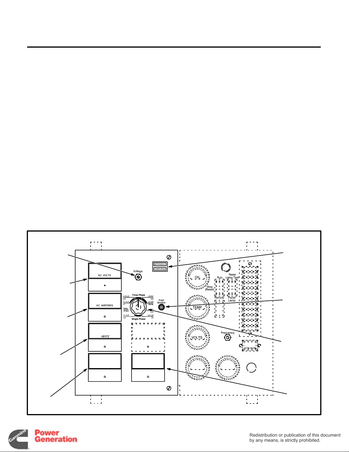
GENERAL
The control box is mounted on top of the generator,
facing the rear. Figure 2-1 points out the components on the AC control panel. Pages 9-3 through
9-6 show the wiring connections.
STANDARD CONTROL PANEL
COMPONENTS
Field Circuit Breaker (CB21) The field circuit
breaker protects the generator from over-excitation.
OPTIONAL CONTROL PANEL
COMPONENTS
AC V oltmeter (M21) The voltmeter indicates output
voltage for the phase selected.
AC Ammeter (M22) The ammeter indicates output
amperage for the phase selected. Input to the am-
meter is from current transformers CT21, CT22 and
CT23.
Phase Selector Switch (S21) The selector switch
is used to select the phase for voltage and amper-
age readings.
Scale Indicator Lamps (DS21 and DS22) The
scale indicator lamps indicate whether to read the
upper or lower scales of the voltmeter and ammeter .
Frequency Meter (M23) The frequency meter indi-
cates output frequency in Hertz (Hz) and engine
speed in RPM.
Wattmeter (M24) The wattmeter indicates output
power in kilowatts (kW).
Powerfactor Meter (M25)
The powerfactor meter
indicates output powerfactor as a percentage of
unity powerfactor.
Output V oltage T rimmer (R21) The output voltage
trimmer can be used to adjust output voltage plus or
minus five percent of nominal voltage.
OUTPUT
VOLTAGE
TRIMMER
AC
VOLTMETER
AC
AMMETER
FREQUENCY
METER
WATTMETER
SCALE
INDICATOR
LAMPS
FIELD
CIRCUIT
BREAKER
PHASE
SELECTOR
SWITCH
POWER
FACTOR
METER
FIGURE 2-1. AC CONTROL PANEL
2-1
Page 10

AUTOMATIC VOLTAGE REGULATOR
Redistribution or publication of this document
by any means, is strictly prohibited.
Redistribution or publication of this document
by any means, is strictly prohibited.
(AVR) ADJUSTMENTS
Check and readjust the VOLTS pot, if necessary,
each time the STABILITY pot is readjusted.
The automatic voltage regulator is mounted on the
back wall of the control cabinet. It can be adjusted
by means of the potentiometers (pots) shown in Figure 2-2 or 2-3. Figures 2-4 and 2-5 show typical voltage regulating circuits.
These measurements and adjustments are done
while the set is running and require access to uninsulated high voltage parts in the control and power
output boxes.
HIGH VOLTAGE. Touching uninsulated high voltage parts inside the control and
power output boxes can result in severe personal injury or death. Measurements and adjustments must be done with care to avoid
touching high voltage parts.
For your protection, stand on a dry wooden platform or rubber insulating mat, make sure your
clothing and shoes are dry , remove jewelry from
your hands and wear elbow length insulating
gloves.
Jumper Reconnections
Jumpers provide for reconnections to adapt the
voltage regulator to the application. See Figure 2-2.
Reconnect the response jumper, if necessary, so
that terminal A connects to terminal C if generator
output is 90 kW o r less, B to C if generator output is
greater than 90 kW but less than 550 kW and A to B
if output is greater than 550kW. Reconnect the frequency jumper, if necessary, to correspond to the
application frequency.
Voltage and Voltage Stability Adjustments
Use the control panel mounted voltage trimmer, if
provided, for small voltage adjustments. Measure
generator output voltage while the set is running
without load at the nominal frequency. If the trimmer
does not provide enough adjustment, lock it at its
midpoint. Then turn the VOLTS pot fully counter-
clockwise and the STABILITY pot to its midpoint. If
the red LED (light emitting diode) on the board
lights, refer to Jumper Reconnections and to UFRO
Adjustments. Then turn the VOLTS pot clockwise
until rated voltage is obtained. If voltage becomes
unstable when a large load is connected, turn the
STABILITY pot clockwise until voltage is stable.
UFRO Adjustments
The voltage regulator has an under-frequency
protection circuit having a threshold frequency that
can be preset (typically at 59 Hz for 60 Hz applications and 49 Hz for 50 Hz applications). The red
LED on the board lights when frequency dips below
the threshold. The threshold frequency is preset by
turning the UFRO (under frequency roll off) pot
clockwise to raise it and counterclockwise to lower
it. Determine threshold frequency by lowering generator frequency until the LED lights. Note that Dip
and Dwell adjustments, below, are related.
Dip Adjustments
The DIP pot adjusts the voltage vs. frequency slope
of the generator for frequencies below the threshold
preset by the UFRO pot. Turning the DIP pot clockwise increases the slope (for greater voltage roll off
as frequency drops), making it easier for the engine
to pick up a large load, but also increasing the voltage dip. The generator voltage vs. frequency slope
is the same above and below the threshold frequency when the pot is turned fully counterclockwise.
Dwell Adjustments
The DWELL pot times voltage recovery when frequency dips below the preset threshold. Clockwise
adjustment increases dwell time. Full counterclockwise adjustment eliminates dwell, in which case,
voltage recovery follows engine speed recovery.
Droop Adjustments
The DROOP pot is for adjusting the input signal
from the droop compensating CT in paralleling applications. DROOP is preset at the factory for five
percent droop at full load and zero power factor.
V / Trim Adjustments
The V / Trim pot is for adjusting the input signal from
a VAR / PF controller in utility paralleling applications. Full clockwise adjustment is normal, resulting
in maximum sensitivity . The auxiliary controller has
no effect when the pot is turned fully counterclockwise.
EXC, OVER V, I / LIMIT, STAB/1and RMS
These pots are factory preset and do not require adjustment.
2-2
Page 11
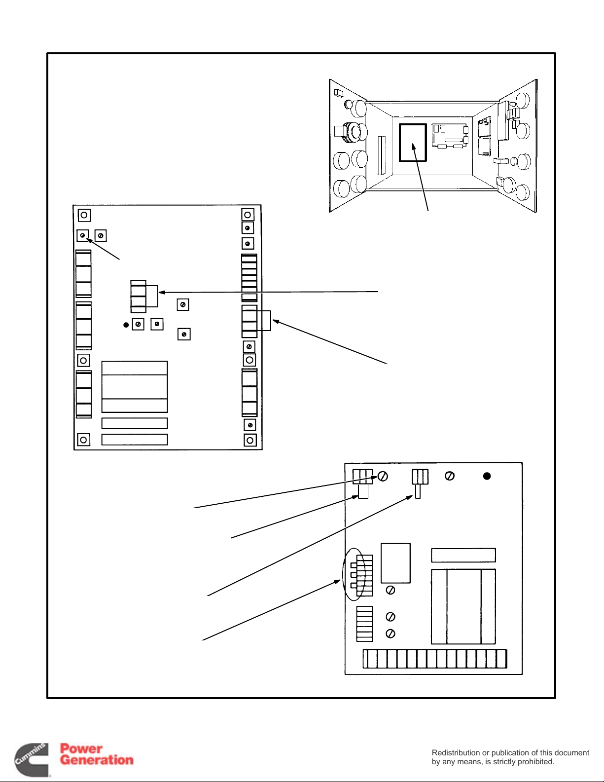
PMG-EXCITED GENERATORS
Redistribution or publication of this document
by any means, is strictly prohibited.
Redistribution or publication of this document
by any means, is strictly prohibited.
I/LIMIT
VOLTS
LED
1
2
3
UFRO
MX321
DIP
V/TRIM
DROOP
STABILITY
DWELL
EXC
OVER V
VOLTAGE REGULATOR
(VR21)
FREQUENCY JUMPER:
50 HZ—3-2
60 HZ—3-1
A
B
C
RESPONSE JUMPER:
A TO C—UNDER 90 KW
B TO C—90-550 KW
A TO B—OVER 550 KW
SELF-EXCITED GENERATORS
ABC
60C 50
UFRO
LED
STABILITY
RESPONSE JUMPER:
A TO C—UNDER 90 KW
B TO C—90-550 KW
A TO B—OVER 550 KW
FREQUENCY JUMPER:
50 HZ—C-50
60 HZ—C-60
THESE JUMPERS
MUST BE:
2-3, 4-5 AND 6-7
FIGURE 2-2. VOLTAGE REGULATOR ADJUSTMENT POTS AND SELECTION JUMPERS
(BEGINNING JANUARY 1990)
2-3
8
7
6
5
4
3
2
1
SX440
VOLTS
DROOP
V/TRIM
Page 12
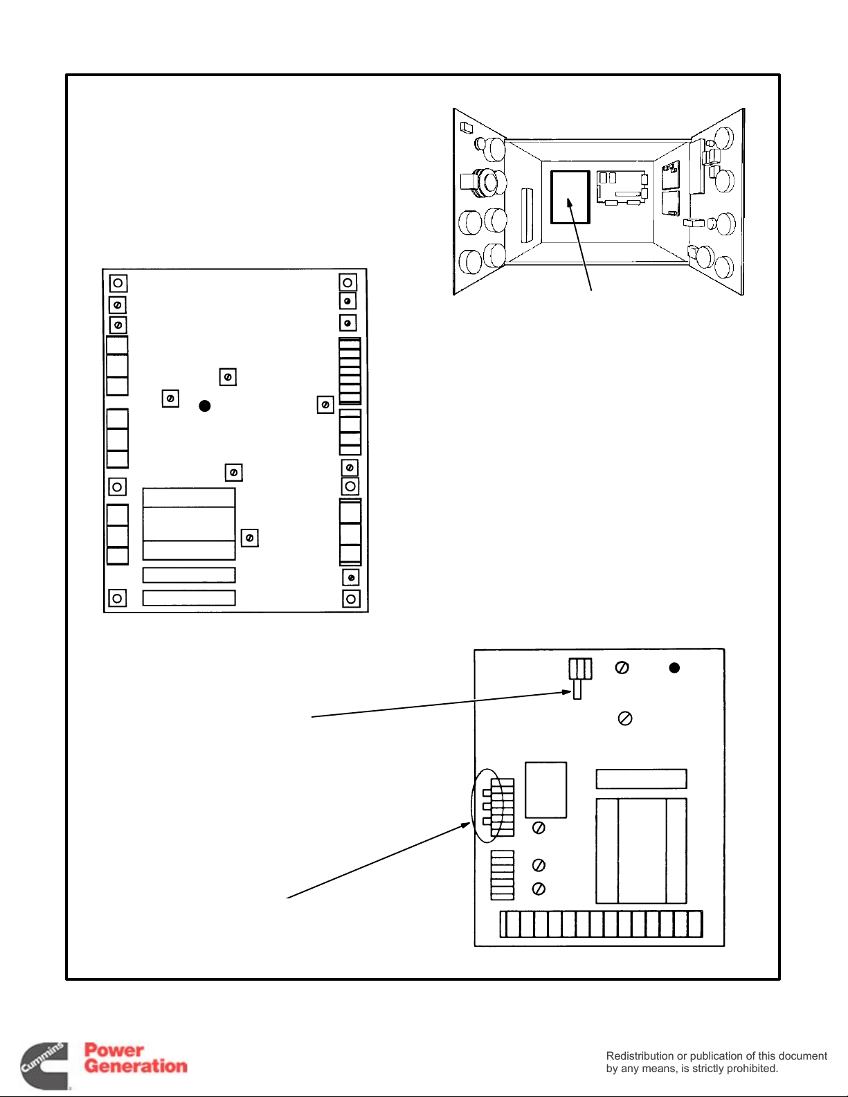
PMG-EXCITED GENERATORS
Redistribution or publication of this document
by any means, is strictly prohibited.
Redistribution or publication of this document
by any means, is strictly prohibited.
I/LIMIT
VOLTS
UFRO
DIP
LED
STABILITY
STAB/1
RMS
V/TRIM
DROOP
EXC
OVER V
VOLTAGE REGULATOR
(VR21)
SELF-EXCITED GENERATORS
60C 50
UFRO
LED
FREQUENCY JUMPER:
50 HZ—C-50
60 HZ—C-60
THESE JUMPERS
MUST BE:
2-3, 4-5 AND 6-7
FIGURE 2-3. VOLTAGE REGULATOR ADJUSTMENT POTS AND SELECTION JUMPERS
(PRIOR TO JANUARY 1990)
2-4
8
7
6
5
4
3
2
1
STABILITY
VOLTS
DROOP
V/TRIM
Page 13
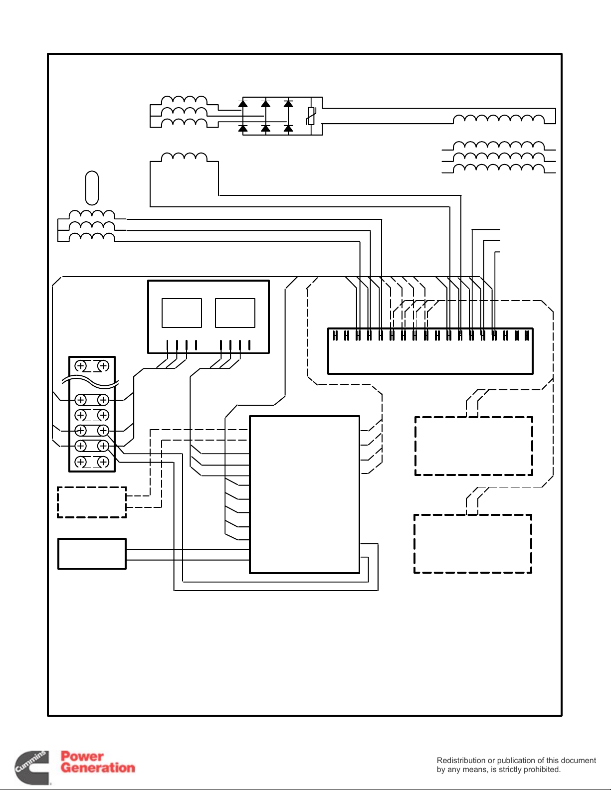
PMG
Redistribution or publication of this document
by any means, is strictly prohibited.
Redistribution or publication of this document
by any means, is strictly prohibited.
ROTOR
N
S
PMG
STATOR
EXCITER
ROTOR
EXCITER
STATOR
ROTATING
RECTIFIERS
MAIN
ROTOR
MAIN
STATOR
8
7
6
OUTPUT
VOLTAGE
SENSING
LEADS
(NOTE 2)
TB21
32
6
25
24
7
23
8
22
21
VOLTAGE
TRIMMER R21
(NOTE 4)
FIELD CIRCUIT
BREAKER
CB21
ISOLATION TRANSFORMER
(NOTE 3)
INPUT OUTPUT
786− 786−
2
1
8
7
6
X
VOLTAGE
XX
REGULATOR
P4
P3
P2
K1
K2
MX321
(VR21)
K1K2 P2 P3 P4 S2 S1 A2 A1XXXX 8 7 6 3 2 1
X
AUXILIARY TERMINAL BOARD
A2
A1
S2
S1
E1
E0
WHEN PARALLELING WITH
A GENERATOR SET OR
UTILITY, TERMINALS S1
AND S2 ARE FOR
CONNECTING A DROOP
COMPENSATING CT
WHEN PARALLELING WITH
A UTILITY, TERMINALS A1
AND A2 ARE FOR
CONNECTING A
VAR / POWER FACTOR
CONTROLLER
1. Connect like numbered terminals on auxiliary
terminal board and voltage regulator.
2. See the appropriate reconnection diagram for
connecting sensing leads 6, 7 and 8.
3. When the generator is connected for singlephase output, voltage regulator terminal 6 is
FIGURE 2-4. TYPICAL VOLTAGE REGULATING CIRCUITS FOR PMG-EXCITED GENERATORS
— NOTES —
not connected to the isolation transformer but
is jumpered to voltage regulator terminal 8.
4. There must be a jumper between voltage regulator terminals 1 and 2 when voltage trimmer
R21 is not used.
2-5
Page 14
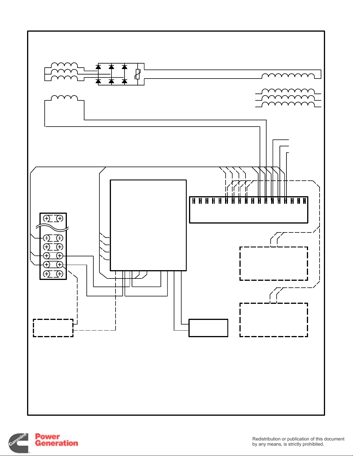
EXCITER
Redistribution or publication of this document
by any means, is strictly prohibited.
Redistribution or publication of this document
by any means, is strictly prohibited.
ROTOR
ROTATING
RECTIFIERS
MAIN
ROTOR
6
7
8
EXCITER
STATOR
TB21
32
25
24
23
22
21
SX440
VOLTAGE
REGULATOR
S2
S1
A2
A1
(VR21)
21 P4 P2P3
3
MAIN
STATOR
OUTPUT
8
VOLTAGE
7
SENSING
LEADS
6
(NOTE 2)
K1K2 P2 P3 P4 S2 S1 A2 A1XXXX 8 7 6 3 2 1
X
AUXILIARY TERMINAL BOARD
WHEN PARALLELING WITH
A GENERATOR SET OR
UTILITY, TERMINALS S1
K1K2XXX
AND S2 ARE FOR
CONNECTING A DROOP
COMPENSATING CT
VOLTAGE
TRIMMER R21
(NOTE 3)
1. Connect like numbered terminals on auxiliary
terminal board and voltage regulator.
2. See the appropriate reconnection diagram for
connecting sensing leads 6, 7 and 8.
FIGURE 2-5. TYPICAL VOLTAGE REGULATING CIRCUITS FOR SELF-EXCITED GENERATORS
— NOTES —
3. There must be a jumper between voltage regu-
2-6
WHEN PARALLELING WITH
A UTILITY, TERMINALS A1
AND A2 ARE FOR
FIELD CIRCUIT
BREAKER
CB21
CONNECTING A
VAR / POWER FACTOR
CONTROLLER
lator terminals 1 and 2 when voltage trimmer
R21 is not used.
Page 15
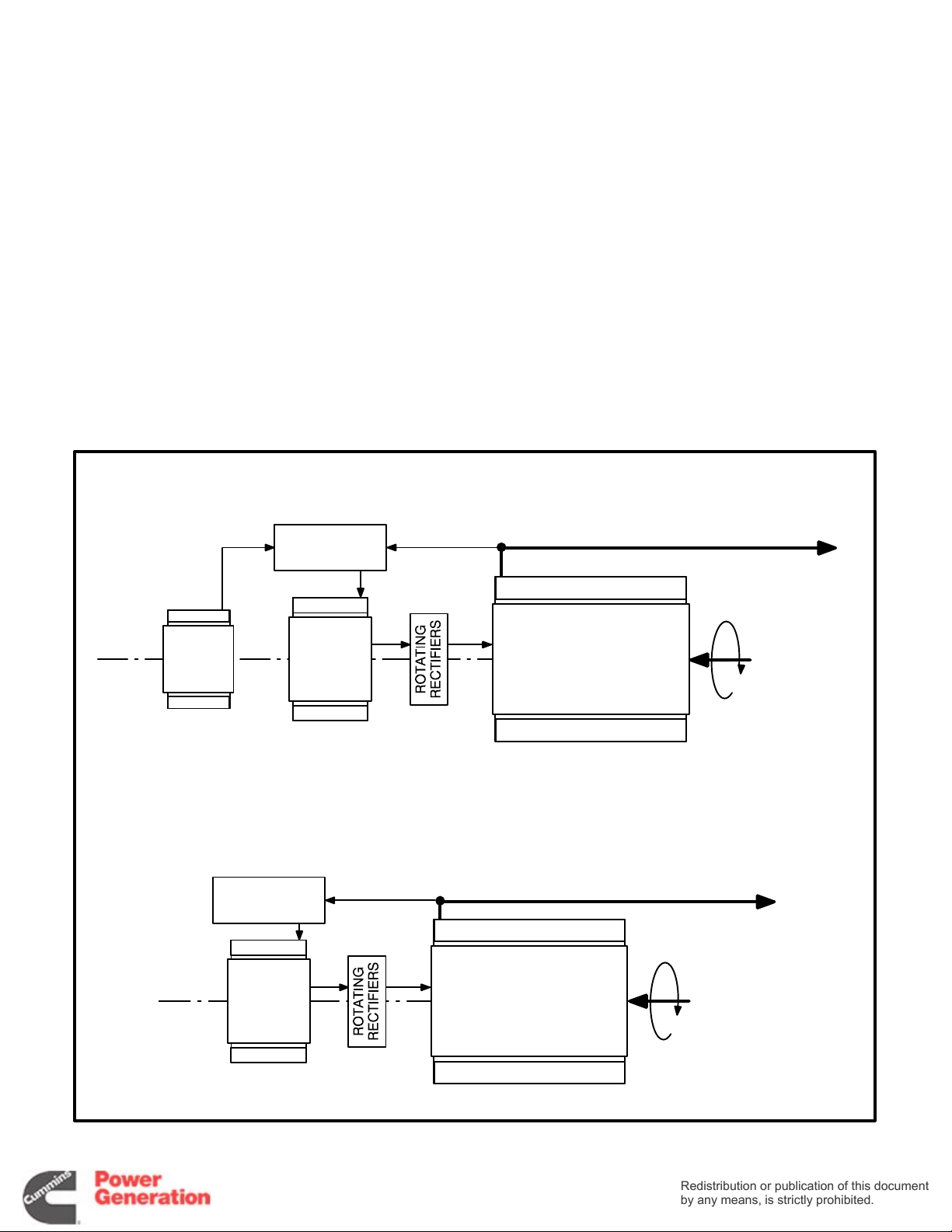
PRINCIPLE OF GENERATOR OPERATION
Redistribution or publication of this document
by any means, is strictly prohibited.
Redistribution or publication of this document
by any means, is strictly prohibited.
1. The generator field (main rotor) is rotated by
the engine to induce output current (AC) in the
main stator windings.
2. Generator output current is proportional to field
strength, which is varied to match the load.
Output voltage and frequency are held
constant by the voltage regulator and engine
governor, respectively.
3. Generator field strength is proportional to field
current, which is supplied by the exciter.
4. The exciter field (stator) induces current in the
exciter rotor windings. A full wave rectifier
bridge (rotating rectifiers) mounted on the exciter rotor converts exciter output (3-phase AC)
to DC. The exciter rotor is mounted on the main
rotor shaft.
PMG-EXCITED GENERATORS
5. Exciter output current is proportional to exciter
field current.
6. The automatic voltage regulator (AVR) regulates exciter field current by comparing generator output voltage and frequency with reference values.
7. PMG-Excited Generators. Exciter field current is supplied by a PMG (permanent magnet)
exciter through the voltage regulator . The PMG
consists of a stator and a permanent magnet
rotor mounted on the end of the main rotor
shaft.
8. Self-Excited Generators. Exciter field current
is supplied by the generator stator through the
voltage regulator. Residual field magnetism initiates “self-excitation” during startups.
PMG
ROTOR
AND
STATOR
AVR
EXCITER
ROTOR
AND
STATOR
AVR
EXCITER
ROTOR
AND
STATOR
ELECTRICAL POWER OUTPUT
MAIN STATOR
MAIN ROTOR
SELF-EXCITED GENERATORS
ELECTRICAL POWER OUTPUT
MAIN STATOR
MAIN ROTOR
ROTATING
MECHANICAL
POWER
INPUT
ROTATING
MECHANICAL
POWER
INPUT
FIGURE 2-6. SCHEMATIC OF GENERATOR OPERATION
2-7
Page 16

Redistribution or publication of this document
by any means, is strictly prohibited.
Redistribution or publication of this document
by any means, is strictly prohibited.
2-8
Page 17
3. Engine Control
Redistribution or publication of this document
by any means, is strictly prohibited.
Redistribution or publication of this document
by any means, is strictly prohibited.
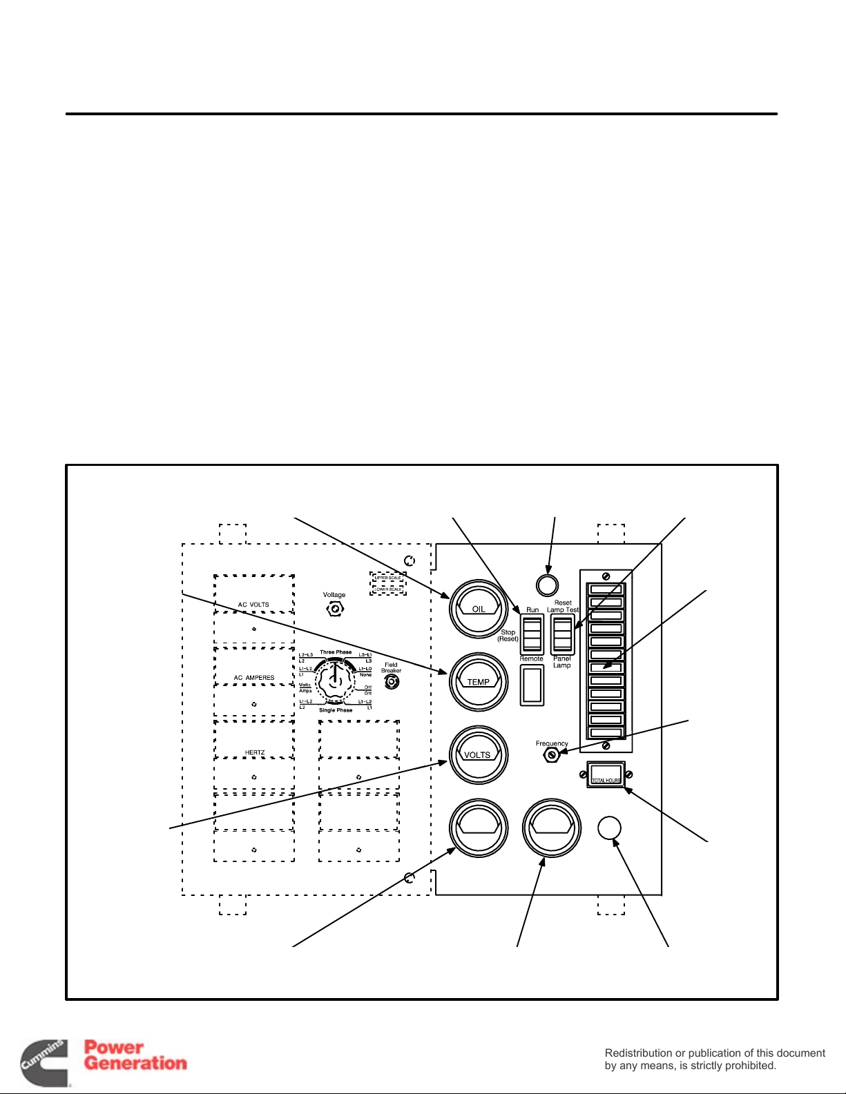
CONTROL PANEL
The control box is mounted on top of the generator,
facing the rear. Figure 3-1 shows the components
on the engine control panel.
STANDARD CONTROL PANEL
COMPONENTS
Run / Stop / Remote Switch (S12) The switch is
pushed to t h e Run position to start and run the generator set and the Stop position to stop the set. The
Remote position allows a remote controller to automatically run the set. The switch must be in the Stop
position when the reset switch (described next) is
used to restore generator set operation following a
fault shutdown.
OIL PRESSURE
GAUGE
COOLANT
TEMPERATURE
GAUGE
RUN/STOP/REMOTE
Reset / Lamp Test / Panel Lamp Switch (S11)
switch is pushed to the Reset position (momentary
contact) to reset the engine control to restore operation following a fault shutdown. The Run / Stop / Re-
mote switch must be in the Stop position for reset to
occur. The Lamp Test position (momentary con-
tact) lights all the fault indicator lamps. Replace
lamps that do not light. The Panel Lamp position
lights the panel illumination lamp.
Oil Pressure Gauge (M11)
The oil pressure gauge
indicates engine oil pressure.
Coolant Temperature Gauge (M12)
The coolant
temperature gauge indicates engine coolant temperature.
RESET/LAMP TEST/
PANEL LIGHT SWITCH
INDICATOR
SWITCH
PANEL
LIGHT
LAMPS
The
DC
VOLTMETER
OIL TEMPERATURE
GAUGE
SPEED
ADJUSTING
RHEOSTAT
HOUR
METER
TACHOMETER EMERGENCY STOP
BUTTON
FIGURE 3-1. ENGINE CONTROL PANEL
3-1
Page 18
DC Voltmeter (M13) The DC voltmeter indicates
Redistribution or publication of this document
by any means, is strictly prohibited.
Redistribution or publication of this document
by any means, is strictly prohibited.
voltage across the battery terminals during operation.
Hour Meter (M14)
The hour meter indicates the accumulated number of hours the set has run. It cannot be reset.
Panel Lamp (DS1 1) The panel lamp illuminates the
control panel.
Detector-7 Fault and Status Indicator Lamps
(A12)
• Run (Green) This lamp indicates that the gen-
erator set is running and that the starter has
been disconnected.
• Pre Low Oil Pressure (Yellow) This lamp indi-
cates that engine oil pressure is abnormally low
(less than 20 psi).
• Low Oil Pressure (Red) This lamp indicates
that the engine shut down because of excessively low engine oil pressure (less than
14 psi).
• Pre High Engine Temperature (Yellow) This
lamp indicates that engine coolant temperature is abnormally high (greater than 220
° F).
• High Engine Temperature (Red) This lamp
indicates that the engine shut down because of
excessively high engine coolant temperature
(greater than 230
° F).
• Overcrank (Red) This lamp indicates that the
engine shut down because it did not start during the timed cranking period (approximately
75 seconds, including two rest periods).
• Overspeed (Red) This lamp indicates that the
engine shut down because of overspeed.
539−0741c2
OPTIONAL CONTROL PANEL
COMPONENTS
Oil Temperature Gauge (M15) The oil temperature
gauge indicates engine oil temperature.
Tachometer (M16) The tachometer indicates en-
gine speed in RPM.
Speed Adjusting Rheostat The speed adjusting
rheostat is used to adjust engine speed from the
control panel (an option with the optional electric
governor).
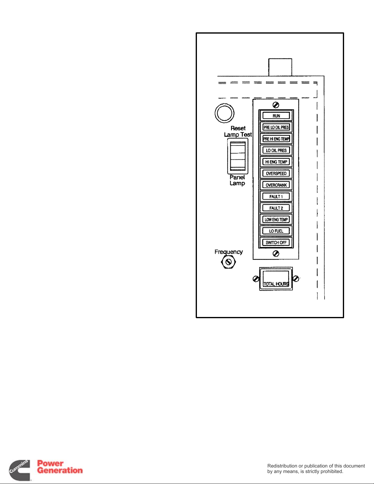
FIGURE 3-2. DETECTOR-12 INDICATOR LAMPS
3-2
Page 19
Emergency Stop Button (S14) The emergency
Redistribution or publication of this document
by any means, is strictly prohibited.
Redistribution or publication of this document
by any means, is strictly prohibited.
stop button is a red, push-in switch used to stop the
engine. The button lights up when it is pushed in.
The button has to be pulled out and the engine control reset to restore operation.
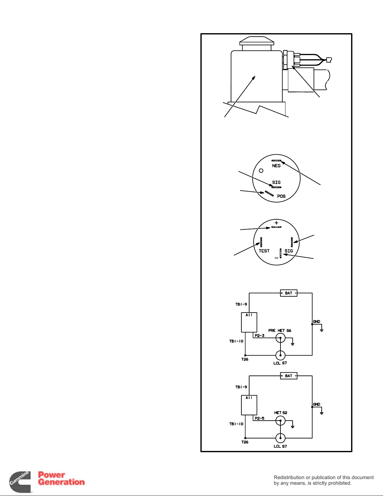
Low Coolant Level Cutout Switch (S7) When
coolant level in the radiator top tank falls below the
switch sensor, the switch closes the circuit to
ground. This switch may be connected in parallel
with the high engine temperature cutout switch to
shut down the engine and light the High Engine
Temperature lamp or in parallel with the pre-high
engine temperature switch to light the Pre High En-
gine Temperature light only.
Detector-12 Fault and Status Indicator Lamps
(A12) The Detector-12 control panel has the five fol-
lowing indicator lamps in addition to the standard
seven.
RADIATOR
TOP TANK
——— SWITCH TERMINALS ——-
SWITCH
S2 OR S6
SWITCHED
B+
(T26)
LOW
COOLANT
LEVEL
SWITCH
(S7)
ENGINE
GROUND
• Low Engine Temperature (Yellow) This lamp
indicates that engine temperature is less than
° F, and the possibility that the engine might
70
not start.
• Low Fuel (Yellow) This lamp indicates that the
fuel level in the supply tank has dropped to less
than the reserve necessary to run the set at full
load for the prescribed number of hours. The
customer has to make connections to use this
lamp.
• Fault 1 (Red) This lamp indicates that the en-
gine shut down because of a system fault. The
customer has to make connections to use this
lamp. The lamp is a part of a 10 second time
delay shutdown circuit. The customer can
make reconnections for non-timed shutdown.
See Engine Control Monitor (ECM).
• Fault 2 (Red) This lamp indicates that the en-
gine shut down because of a system fault. The
customer has to make connections to use this
lamp. The lamp is part of a non-time delay shutdown circuit. The customer can make reconnections for 10 second time delay shutdown.
See Engine Control Monitor (ECM).
SWITCHED
B+
(T26)
NOT
USED
———— SCHEMATICS ————
—— OR ——
ECM
ECM
SWITCH
S2 OR S6
ENGINE
GROUND
WARNING
ONLY
SHUTDOWN
• Switch-off (Flashing Red) This lamp indi-
cates that the Run / Stop / Remote switch is in
the Stop position, which prevents remote, automatic operation.
FIGURE 3-3. LOW COOLANT LEVEL SWITCH
3-3
Page 20
VOLTAGE
Redistribution or publication of this document
by any means, is strictly prohibited.
Redistribution or publication of this document
by any means, is strictly prohibited.
REGULATOR
VR21
ENGINE
CONTROL
MONITOR A11
TIME DELAY
START/STOP
MODULE A15
TERMINAL BOARD
TB21
RUN RELAYS K11
(NOT SHOWN − MOUNTED ON
A BRACKET IN FRONT OF A11)
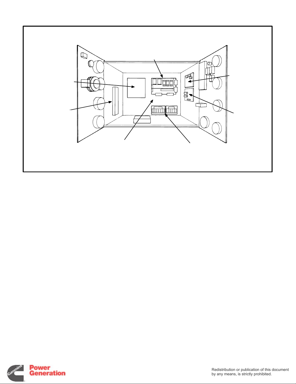
FIGURE 3-4. ARRANGEMENT OF COMPONENTS INSIDE THE CONTROL BOX
CONTROL BOX INTERIOR
Figure 3-4 shows the arrangement of components
inside the control box, including the engine control
monitor and some of the auxiliary components under following headings.
ENGINE CONTROL MONITOR (A11)
The heart of the engine control system is the engine
control monitor (ECM). It is a printed circuit board
assembly mounted on the back wall of the control
box. It starts and stops the engine in response to the
control panel switches, engine sensors and remote
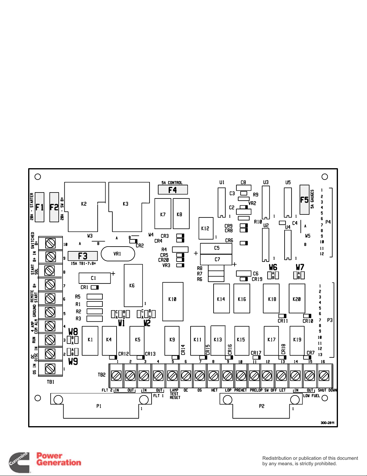
control signals. Figure 3-5 shows the newer ECM
board used in current production and as a direct replacement for older boards. The boards are distinquishable from each other in that the newer boards
have automotive-type fuses and the older boards
have cartridge-type fuses.
Terminals and Connectors
See Pages 9-7 through 9-10 for the appropriate
connection and schematic drawings for the DC control system. See Page 9-16 for typical customer
connections at terminal boards TB1 and TB2 on the
ECM and page 9-17 if the set is also equipped with
the auxiliary relay board.
OVERSPEED
MODULE
ALARM RELAY MODULES
A13 AND A14
ES1561s−
1
Fuses
The ECM has five replaceable fuses to protect it
from overloads and groundfaults. They are:
F1 Starter solenoid circuit, 20 amps
F2 Fuel solenoid (switched B+) circuits, 20 amps
F3 Continuous B+ out to remote circuits, 15 amps
F4 ECM circuits, 5 amps
F5 Engine gauge circuits, 5 amps.
Function Selection Jumpers
Newer ECM boards have six selection jumpers that
can be repositioned to provide the following timed
or non-timed warnings or timed or non-timed shutdowns with warnings:
W1 Jumper Position (jumper W8 must be in the B
position):
A Non-timed warning under FLT 2 condi-
tions.
B Non-timed shutdown and warning under
FLT 2 conditions.
C Timed warning under FLT 2 conditions.
D Timed shutdown and warning under FLT 2
conditions.
3-4
Page 21
W2 Jumper Position (jumper W9 must be in the B
Redistribution or publication of this document
by any means, is strictly prohibited.
Redistribution or publication of this document
by any means, is strictly prohibited.
position):
A Non-timed warning under FLT 1 condi-
tions.
B Non-timed shutdown and warning under
FLT 1 conditions.
C Timed warning under FLT 1 conditions.
D Timed shutdown and warning under FLT 1
conditions.
W6 Jumper Position:
A Warning under Pre-High Engine Tem-
perature conditions.
B Shutdown and warning under Pre-High
Engine Temperature conditions.
W7 Jumper Position:
A Warning under Pre-Low Oil Pressure
conditions.
B Shutdown and warning under Pre-Low
Oil Pressure conditions.
W8 Jumper Position:
A Warning while running or during standby
under FLT 2 conditions.
B Allows selection of functions with W1
jumper.
W9 Jumper Position:
A Warning while running or during standby
under FLT 1 conditions.
B Allows selection of functions with W2
jumper.
87654321 654321
FIGURE 3-5. ENGINE CONTROL MONITOR FUSES AND FUNCTION SELECTION JUMPERS
3-5
Page 22
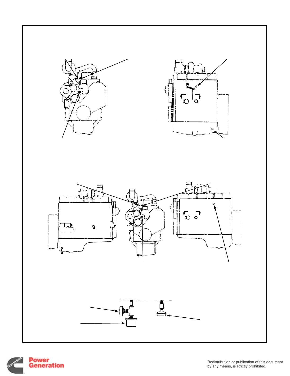
ENGINE SENSORS
Redistribution or publication of this document
by any means, is strictly prohibited.
Redistribution or publication of this document
by any means, is strictly prohibited.
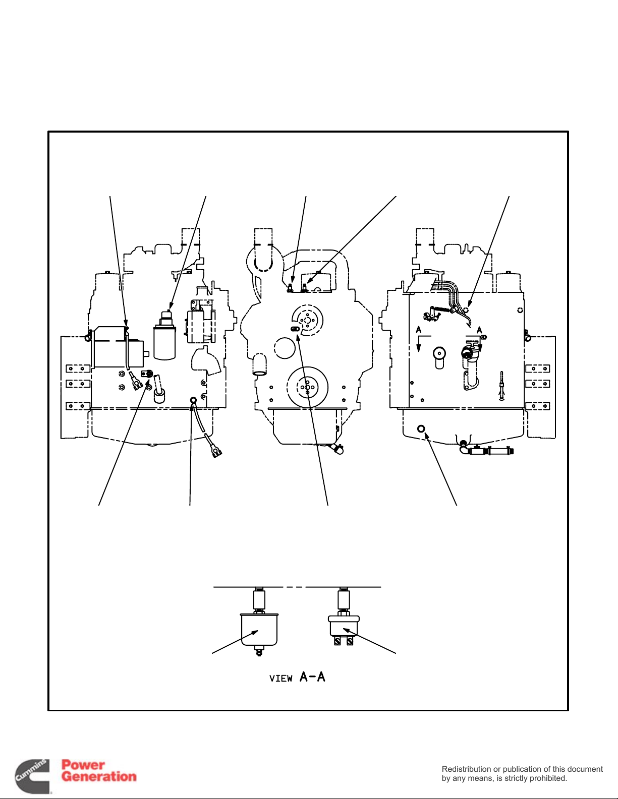
Figures 3-6, 3-7, 3-8 and 3-9 show the locations of
the gauge senders and the coolant temperature
and oil pressure sensing switches to which the ECM
responds. The switches function by closing the fault
or warning circuit to the engine chassis ground (battery negative [-]).
POSITIVE BATTERY
CABLE CONNECTION
POINT (B1)
PRE-LOW OIL
PRESSURE
SENSOR S5
PRE-HIGH ENGINE
TEMPERATURE
SENSOR S6
HIGH ENGINE
TEMPERATURE
SENSOR S2
COOLANT
TEMPERATURE
SENDER E2
GND
AND T26
(SWITCHED B+)
CONNECTION POINT
FIGURE 3-6. ENGINE SENSOR LOCATIONS (FOUR CYLINDER B-SERIES ENGINES)—BEGINNING SPEC H
NEGATIVE
BATTERY CABLE
OIL
PRESSURE
SENDER E1
LOW ENGINE
TEMPERATURE
SENSOR S4
3-6
TEMPERATURE
SENDER E4
LOW OIL
PRESSURE
SENSOR S1
OIL
100-3148, REV
C
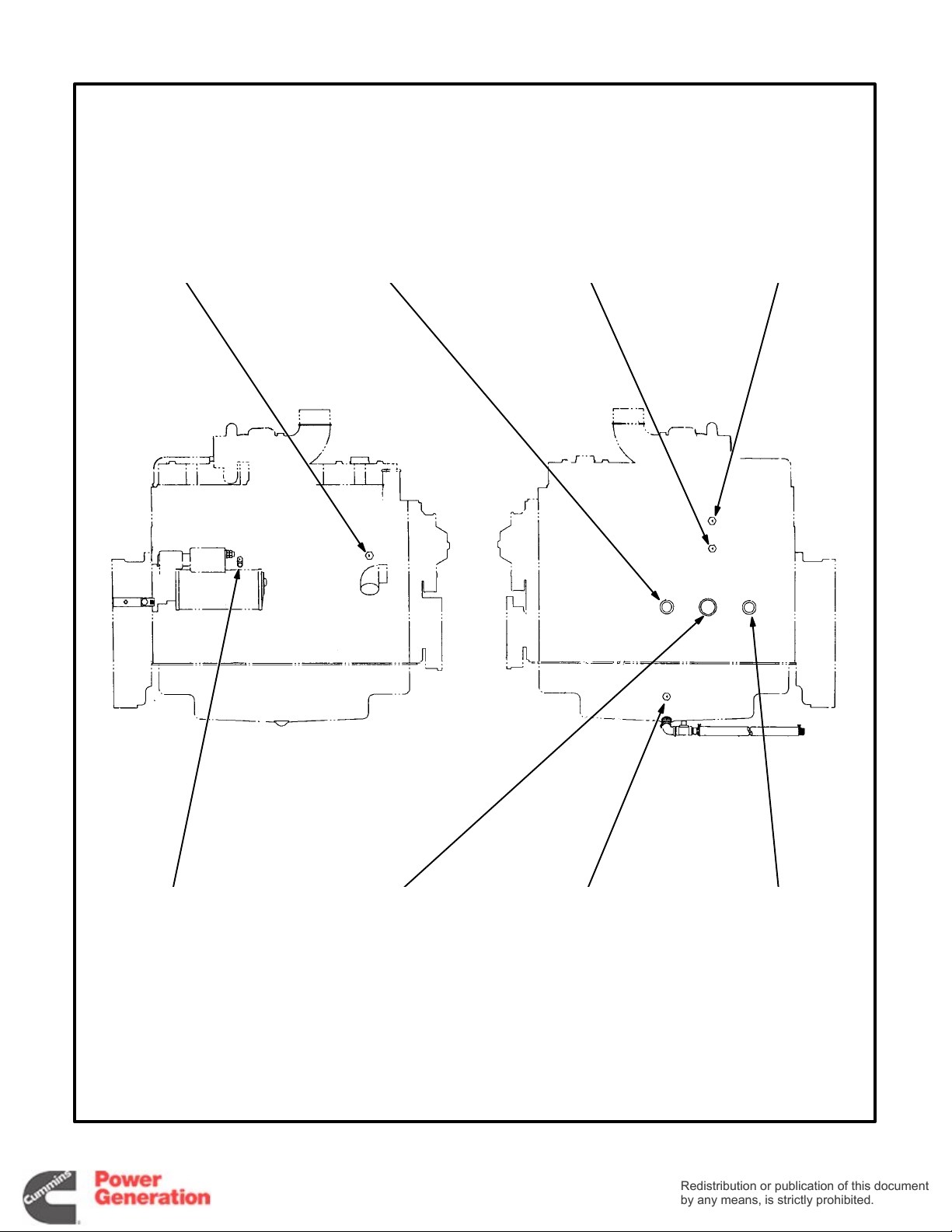
Page 23
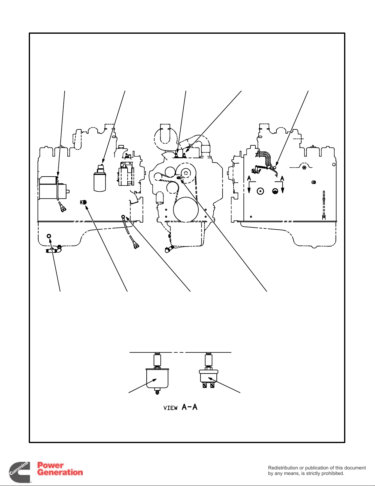
POSITIVE BATTERY
Redistribution or publication of this document
by any means, is strictly prohibited.
Redistribution or publication of this document
by any means, is strictly prohibited.
CABLE CONNECTION
POINT (B1)
PRE-LOW OIL
PRESSURE
SENSOR S5
PRE-HIGH ENGINE
TEMPERATURE
SENSOR S6
HIGH ENGINE
TEMPERATURE
SENSOR S2
COOLANT
TEMPERATURE
SENDER E2
OIL
TEMPERATURE
SENDER E4
FIGURE 3-7. ENGINE SENSOR LOCATIONS (SIX CYLINDER B-SERIES ENGINES)—BEGINNING SPEC H
(SWITCHED B+)
OIL
PRESSURE
SENDER E1
GND
AND T26
NEGATIVE
BATTERY CABLE
CONNECTION POINT
3-7
LOW ENGINE
TEMPERATURE
SENSOR S4
LOW OIL
PRESSURE
SENSOR S1
100-3141, REV
D
Page 24
— FOUR CYLINDER ENGINES —
Redistribution or publication of this document
by any means, is strictly prohibited.
Redistribution or publication of this document
by any means, is strictly prohibited.
HIGH ENGINE TEMPERATURE
SENSOR (S2)
LOW ENGINE TEMPERATURE
SENSOR (S4)
HIGH ENGINE TEMPERATURE
SENSOR (S2)
PRE-HIGH ENGINE
TEMPERATURE SENSOR (S6)
— SIX CYLINDER ENGINES —
COOLANT TEMPERATURE
SENDER (E2)
AA
OIL TEMPERATURE
SENDER (E4)
PRE-HIGH ENGINE
TEMPERATURE SENSOR (S6)
OIL TEMPERATURE
SENDER (E4)
LOW OIL PRESSURE
SENSOR (S1)
OIL PRESSURE
SENDER (E1)
LOW ENGINE TEMPERATURE
SENSOR (S4)
— VIEW A-A —
AA
COOLANT TEMPERATURE
PRE-LOW OIL PRESSURE
SENDER (E2)
SENSOR (S5)
M1695
M1695−1
FIGURE 3-8. ENGINE SENSOR LOCATIONS (B-SERIES ENGINES)—PRIOR TO SPEC H
3-8
Page 25
HIGH ENGINE
Redistribution or publication of this document
by any means, is strictly prohibited.
Redistribution or publication of this document
by any means, is strictly prohibited.
TEMPERATURE
SENSOR (S2)
PRE-LOW OIL
PRESSURE
SENSOR (S5)
PRE-HIGH ENGINE
TEMPERATURE
SENSOR (S6)
COOLANT
TEMPERATURE
SENDER (E2)
LOW ENGINE
TEMPERATURE
SENSOR (S4)
FIGURE 3-9. ENGINE SENSOR LOCATIONS (C-SERIES ENGINES)
OIL
PRESSURE
SENDER (E1)
3-9
OIL
TEMPERATURE
SENDER (E4)
LOW OIL
PRESSURE
SENSOR (S1)
M1720
Page 26
AUXILIARY CONTROL COMPONENTS
Redistribution or publication of this document
by any means, is strictly prohibited.
Redistribution or publication of this document
by any means, is strictly prohibited.
The set might be equipped with one or more of the
following components.
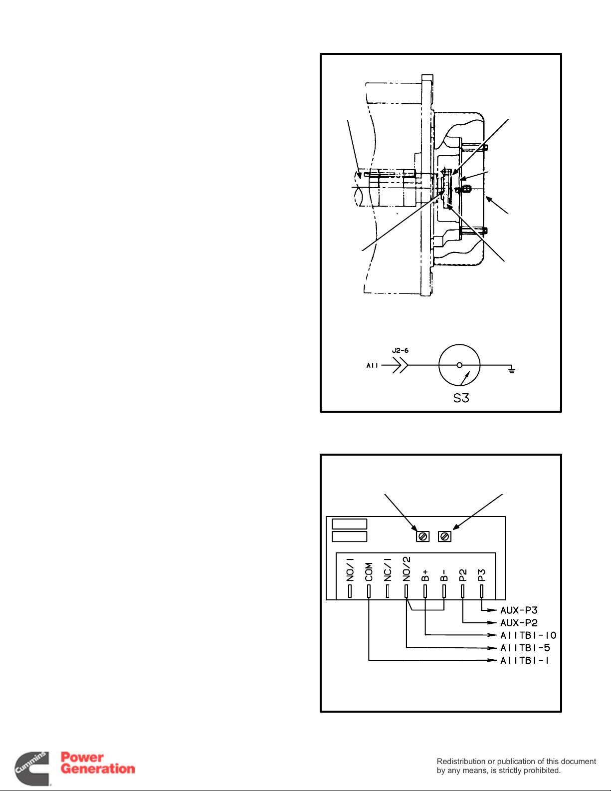
Mechanical Overspeed Switch (Standard)
The mechanical overspeed switch is bolted to the
end of the generator rotor shaft.
1. Check overspeed cutout RPM and turn the adjustment screw, i f necessary, so that shutdown
occurs within the following RPM ranges:
60 Hz Sets 2000 to 2200 RPM. . . . . . . .
50 Hz Sets 1800 to 2100 RPM. . . . . . . .
2. Replace the switch if the cutout speed adjustment results in an air gap between the magnet
and the fly arm of less than 0.005 inches (0.13
mm).
3. Torque the center rotor bolt to 40 ft-lbs (54 Nm)
when replacing the switch.
MAIN
ROTOR
SHAFT
ROTOR
CENTER
BOLT
CUTOUT
SWITCH
ASSEMBLY
SWITCH
CONTACT
BRACKET
SWITCH
COVER
CUTOUT RPM
ADJUSTMENT
SCREW
Es1860s
—SCHEMATIC—
Electronic Overspeed Module (Optional)
PMG-excited generators are equipped with an electronic overspeed module in the control box. The
module senses PMG output frequency to determine
generator speed (frequency). Adjust the overspeed
pot to cut out at 1800 to 1900 RPM for 50 Hz sets
and 2100 to 2200 RPM for 60 Hz sets. Do not adjust
the cranking pot.
FIGURE 3-10. MECHANICAL OVERSPEED SWITCH
FOR FACTORY
ADJUSTMENTS
ONLY
* − AUXILIARY TERMINAL BLOCK
OVERSPEED
ADJUSTMENT
POT
*
*
612-6488
FIGURE 3-11. ELECTRONIC OVERSPEED MODULE
3-10
Page 27
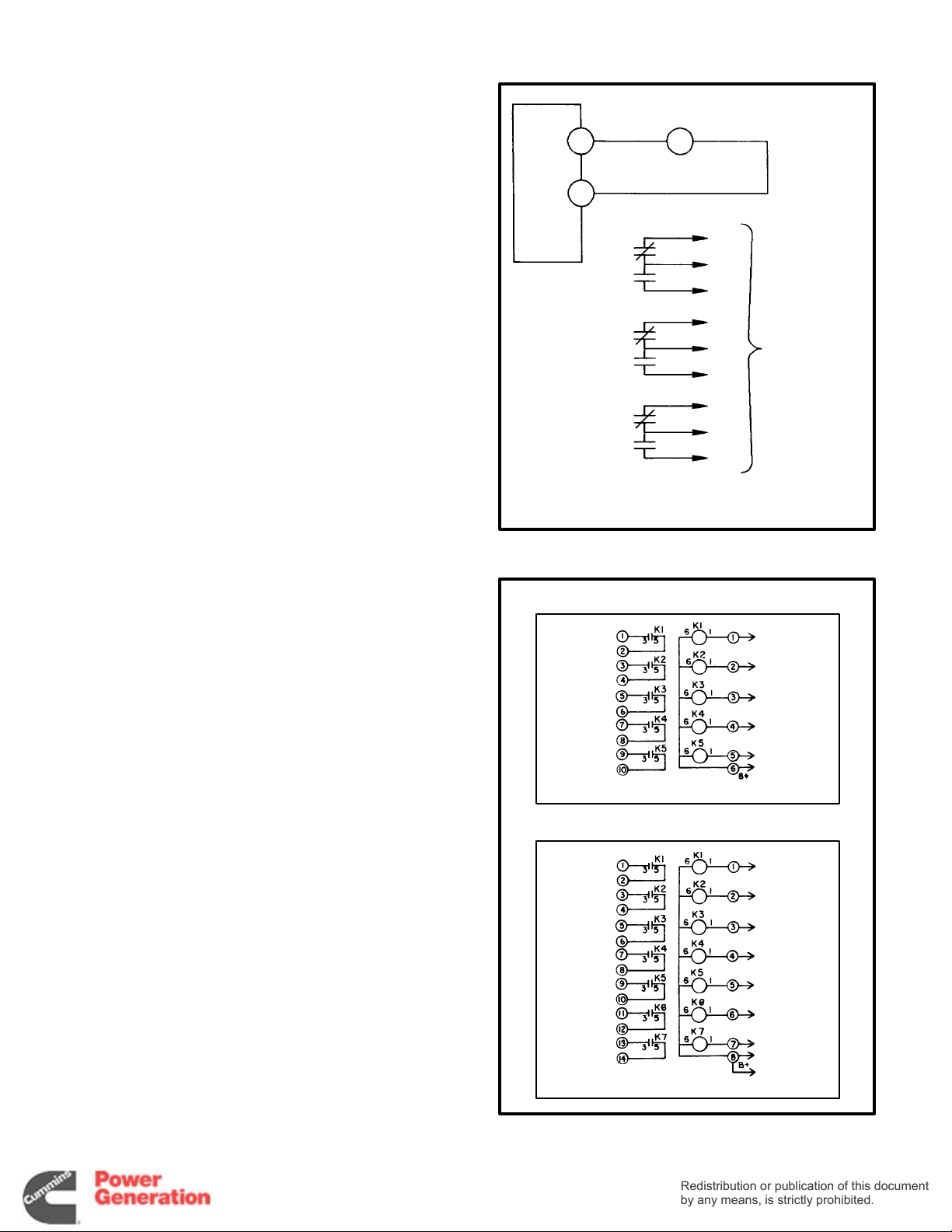
Run Relays (K11)
Redistribution or publication of this document
by any means, is strictly prohibited.
Redistribution or publication of this document
by any means, is strictly prohibited.
The set can be equipped with one to three 3-pole,
double-throw relays to control auxiliary equipment
such as fans, pumps, and motorized air dampers.
The relays are mounted on a standoff bracket in
front of the ECM.
A11
TB1
TB1
10
K11
B
A
5
The contacts are rated:
• 10 amps at 28 VDC or 120 VAC, 80% PF
• 6 amps at 240 VAC, 80% PF
• 3 amps at 480 VAC, 80% PF
The set might instead be equipped with an auxiliary
relay board. If so, see Auxiliary Relay Board (ARB).
Alarm Relay Modules (A13 and A14)
The set can be equipped with relay modules to interface with a remote annunciator that is powered
independently of the control circuit of the set. Sets
with Detector-7 need module A13 and sets with Detector-12, modules A13 and A14.
These are all normally open contacts and they are
rated:
• 15 amps at 250 VAC
• 15 amps at 30 VDC
K11
K11
K11
FIGURE 3-12. RUN RELAYS
A14
TB1
FAULT#1
FAULT#2
LET
LOW FUEL
SWITCH
OFF
1
7
4
5
3
9
2
8
6
CUSTOMER
CONNECTIONS
TB2
A11-TB2-4
A11-TB2-2
A11-TB2-13
A11-TB2-15
A11-TB2-12
A13-TB2-8
The set might instead be equipped with an auxiliary
relay board. If so, see Auxiliary Relay Board (ARB).
3-11
A13
TB1
RUN
PRE -LOP
PRE-HET
LOP
HET
OS
OC
TB2
A11-TB1-3
A11-TB2-11
A11-TB2-10
A11-TB2-9
A11-TB2-8
A11-TB2-7
A11-TB2-6
A11-TB1-7
A14-TB2-6
(12 LIGHT)
FIGURE 3-13. ALARM RELAY MODULES
Page 28

Auxiliary Relay Board (ARB)
Redistribution or publication of this document
by any means, is strictly prohibited.
Redistribution or publication of this document
by any means, is strictly prohibited.
The following describes the design/functional criteria for the auxiliary relay board (ARB) with a Detector-7 or -12 Genset control. The board is mounted
directly on top of the ECM using standoffs and has
access holes for the fuses located on the ECM.
There are two versions of the ARB; with and without
the set of 12 Fault relays (Figure 3-14). Page 9-17 is
a detailed connection diagram for the ARB.
The set might instead be equipped with separate
run and alarm relay modules. If so, see Run Relay
(K11) and Alarm Relay Modules (A13 and A14).
Terminal Blocks:
• TB1 − ARB TB1 and ECM TB1 are identically
numbered and provide the same remote control connection points. Note that additional terminals are provided for terminals 5, 7, and 10 of
ARB TB1.
• TB2 through TB5 − Connection points for re-
lays K1 through K3. TB2 provides the N/O and
N/C connections (three form ‘C’ contacts for
each relay). TB3 through TB5 provide the common connection points (TB3 for K1, TB4 for K2
and TB5 for K3).
• TB6 and TB7 − Connection points for fault re-
lays K4 through K15. Three terminals are provided for each relay, which are labeled COM,
N/C, N/O.
Plug-In Relays (K1, K2, K3):
equipped with one to three 3-pole, double-throw relays. These relays (K1, K2, K3) are field changeable
plug-in relays for easy field addition and replacement.
Each relay can be operated as a RUN, COMMON
ALARM, or ISOLATED COIL with the changing of a
jumper.
The relay contact ratings are:
The ARB can be
• 10 amps at 28 VDC or 120 VAC, 80% PF
• 6 amps at 240 VAC, 80% PF
• 3 amps at 480 VAC, 80% PF
Jumper Positions for Plug-In Relays:
W1, W2 and W3 perform the same functions for
Jumpers
their respective relays, W1 for relay K1, W2 for relay
K2, and W3 for relay K3. They can be located in any
of 3 positions (A, B, C) independently of each other.
• Jumper Position A (Run) − The relay oper-
ates as a Run relay, energizing when SW B+ is
applied from the ECM.
• Jumper Position B (Common Alarm) − The
relay operates as a Common Alarm relay. The
relay energizes any time there is an engine
shutdown. This signal is provided from the
ECM.
• Jumper Position C (Isolated) − The relay op-
erates as an Isolated relay. The relay coil is energized by a customer applied B+ signal
through the terminal block; TB3-1 for relay K1,
TB4-1 for relay K2, and TB5-1 for relay K3.
Jumpers W11, W12, and W13 perform the same
functions for their respective relays; W11 for relay
K1, W12 for relay K2, and W13 for relay K3. They
can be located in two different positions (A, B) independently of one another.
• Jumper Position A − The relay operates iso-
lated from the board. The customer provides
the circuit completion through terminal block;
TB3 for relay K1, TB4-5 for relay K2, and TB5-5
for relay K3. The customer can operate the
relay with switched ground logic or use this
relay in the middle of more complex logic circuits if needed.
• Jumper Position B − The relays operate with
the coils connected to ground through the
board connections. The coil will require a B+
signal to energize with the jumper in this position.
Fault Relays (K4 through K15):
relay modules are used to operate a remote alarm
annunciator that has an independent power source.
This allows the use of either AC or DC for alarm
drives. The relays are energized through the latching relays on the ECM and provided N/O and N/C
contacts for each external alarm connection.
The 12 relays with form ‘C’ contacts are rated:
These optional
• 10 Amp, 120 VAC
• 10 Amp. 30 VDC
3-12
Page 29
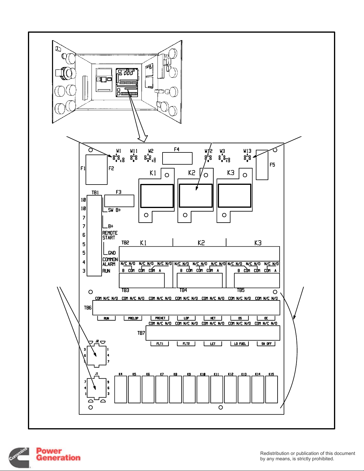
JUMPERS JUMPERS
Redistribution or publication of this document
by any means, is strictly prohibited.
Redistribution or publication of this document
by any means, is strictly prohibited.
RUN RELAY
MODULE(S)
K1 K2 K3
J1, J2 WIRE
HARNESS PLUG
CONNECTIONS
FROM ECM
TB6, TB7 AND
RELAYS K4
THROUGH K15
ARE OPTIONAL
300−4111c
FIGURE 3-14. AUXILIARY RELAY BOARD (ARB)
3-13
Page 30

Over / Under Voltage Module (A17)
Redistribution or publication of this document
by any means, is strictly prohibited.
Redistribution or publication of this document
by any means, is strictly prohibited.
The set can be equipped with an adjustable voltage-sensitive relay usually connected into the Fault
1 circuit (Detector-12 controls only) to shut down
the set when the output voltage is over or under
nominal voltage by the preselected percentage
(typically 10 percent over and under).
With the module is an adjustable time delay relay
(K17) to prevent nuisance tripping. An adjustment
of 25 percent is equivalent to about 2.5 seconds
delay.
Recalibrate the module as follows before installing
it on 139/240 VAC or 277/480 VAC sets.
1. Remove the two screws that secure the top to
the case of the module and withdraw the top
assembly.
2. Adjust the SET pot for the UNDER setpoint on
the face of the top assembly to 75 percent.
3. Apply single-phase, 60 Hertz, 104.25 VAC
across terminals L and N.
4. Adjust pot R25 on the PC board until the relay
trips (de-energizes).
5. Adjust the SET pot for the OVER setpoint on
the face of the top assembly to 125 percent.
6. Apply single-phase, 60 Hertz, 173.75 VAC
across terminals L and N.
7. Adjust pot R26 on the PC board until the relay
trips (energizes).
8. Repeat the above steps until no adjustments
are necessary.
9. Reassemble the module.
10. On the module nameplate mark out the factory
calibration value for monitored voltage (120 V)
and write in 139 V.
*
*
**
* CONNECTED TO TB11-45 WHEN GENERA-
TOR IS PARALLELED.
** CONNECTED TO GENERATOR LEAD LO
WHEN THE GENERATOR IS CONNECTED
FOR SINGLE PHASE.
FIGURE 3-15. OVER / UNDER VOLTAGE
MODULE
Over / Under Frequency Module (A19)
The set can be equipped with an adjustable frequency-sensitive relay to shut down the set when
the output frequency (Hz) is over or under nominal
frequency by the preselected amount. It is usually
connected into the Fault 2 circuit (Detector-12 con-
trols only) if the over / under voltage module is also
provided. Set points are typically 5 Hertz over and
under nominal frequency (50 or 60 Hertz) and reset
points 3 Hertz over and under.
3-14
300-314
FIGURE 3-16. OVER / UNDER FREQUENCY
MODULE
1
Page 31

Time Delay Start / Stop Module (A15)
Redistribution or publication of this document
by any means, is strictly prohibited.
Redistribution or publication of this document
by any means, is strictly prohibited.
The set can be equipped with a module to delay
starting and stopping when the start and stop signals are received from the remote controller. It i s ad -
justable to delay starts from 1 to 15 seconds to prevent nuisance starts in installations where momentary power interruptions are frequent. It is adjustable to delay stops 1 to 30 minutes to allow the
prime source of power time to stabilize.
TIME DELAY START
POTENTIOMETER
A11-TB1-2
(PRIMARY START DISCONNECT)
TIME DELAY STOP POTENTIOMETER
TB1
A11-TB1-6
(REMOTE START)
A11-TB1-3
(SECONDARY START DISCONNECT)
A11-TB1-5
(B−)
FIGURE 3-17. TIME DELAY START / STOP MODULE
REMOTE
CONTROL
A11-TB1-7
(B+)
A11-TB1-7
(B+)
ES1855s
3-15
Page 32

SEQUENCE OF OPERATION
Redistribution or publication of this document
by any means, is strictly prohibited.
Redistribution or publication of this document
by any means, is strictly prohibited.
The sequence of operation is as follows. Refer to
the schematic on Page 9-8 or 9-10, as appropriate.
1. The ECM is powered by cranking battery voltage (24 VDC). Terminal TB1-9 is connected to
battery positive (+) and connector P1-6 to bat-
tery negative (-).
2. The starting cycle begins when relay K7 is
powered, either manually by pushing the panel
Run switch, or automatically by a remote controller connected at terminal TB1-6. (The panel
switch must be in the Remote position for remote, automatic operation.)
3. Relay K7 powers relays K2 and K3.
4. Relay K2 powers the engine gauges and termi-
nal TB1-10, to which the fuel solenoid and igni-
tion module are connected.
5. Relay K3 powers terminal TB1-8 to which start-
er relay K4 is connected. Engine cranking begins.
6. The engine starts and runs up to governed
speed in a matter of seconds.
7. The starter is disconnected when engine
speed gets to about 600 RPM. This is done by
relay K10 or K14, whichever acts first to open
the circuit powering relay K3.
8. Relay K10 is powered by the generator output
voltage (120 V AC) through plug-in connectors
P1-1 and P1-2. The remote Run indicator lamp
should light (connected through terminal
TB1-3).
9. Relay K14 is powered by the engine-driven
battery charging alternator (24 VDC) through
plug-in connector P1-3. The panel Run indicator lamp should light. Relays K10 and K14 are
redundant.*
10. Relays K2 and K3 are deenergized (by latching
relay K6) causing shutdown to occur if the engine does not start within 75 seconds. The
Overcrank indicator lamp lights and common
alarm terminal TB1-4 is powered.
The ECM has a cycle crank feature whereby the
engine is cranked for three 15 second periods
alternated with two 15 second rest periods.
11. Relay K3 is deenergized (by latching relay K6)
causing shutdown to occur during operation
when a low oil pressure, high engine temperature or engine overspeed condition is sensed
or the optional emergency stop button is
pressed. The appropriate fault indicator lamp
lights and common alarm terminal TB1-4 is
powered. (There is no fault lamp for emergency
stop.)
The low oil pressure and high engine temperature shutdowns have 10 second time delays to
allow oil pressure and engine temperature to
stabilize during startup.
12. To restore operation after a shutdown fault has
been serviced, reset latching relay K6 by push-
ing the panel Stop switch and then the Reset
switch. The set should run or be ready to run
when the panel switch is pushed to Run or to
Remote.
If the emergency stop switch has been used, the
control will have to be reset to restore operation.
First pull the emergency stop switch button and
then push the panel Stop and Reset switches.
13. The set is stopped manually by pressing the
panel Stop switch or automatically by a remote
controller. (The panel switch must be in the Re-
mote position for remote, automatic operation.)
* On older ECM boards (those having cartridge-type fuses):
• If the starter disconnects normally but the panel Run indicator lamp does not light, the DC (K14) starter disconnect circuit is
not working.
• If the starter disconnects normally but neither the panel nor the remote Run indicator lamps light, the AC (K10) starter dis-
connect circuit is not working.
* On newer ECM boards (those having automotive-type fuses):
• If the starter disconnects normally but neither the panel nor the remote Run indicator lamps light, the AC (K10) starter dis-
connect circuit is not working.
• Both the remote and the panel Run indicator lamps will light even if the DC (K14) starter disconnect circuit is not working.
Check the DC voltmeter to determine whether or not the battery charging alternator is working.
3-16
Page 33

4. Troubleshooting
Redistribution or publication of this document
by any means, is strictly prohibited.
Redistribution or publication of this document
by any means, is strictly prohibited.
These troubleshooting charts are designed to help
you think through generator set problems. To save
time troubleshooting, read the entire manual ahead
of time to understand the generator set. Try to think
through problems. Go over what was done during
the last service call. The problem could be as simple
as an empty fuel tank, closed fuel shutoff valve,
loose wire, blown fuse or tripped circuit breaker.
THE ENGINE DOES NOT CRANK
The Run-Stop-Remote switch is at Stop.
(The Switch-Off light will be flashing, if
provided.)
The Emergency Stop switch has been
used. (No fault lamp is on.)
WARNING
There are hazards present in troubleshooting that can cause equipment damage,
severe personal injury or death. Troubleshooting must be performed by qualified persons
who know about fuel, electrical and machinery
hazards. Read the safety precautions page and
carefully observe all instructions and precautions in this manual.
Push the Run-Stop-Remote switch to Run or Remote.
Pull the Emergency Switch button. To reset the engine control, push the Run-Stop-Remote switch to
Stop and the Reset switch to Reset. Then push the
Run-Stop-Remote switch to Run or Remote.
The remote control circuit is faulty.
A Fault Shutdown is being indicated by
one of the red lights on the control panel.
A Lo Shutdown is being indicated on the
day tank pump control panel (if provided).
Continued on next page.
Push the Run-Stop-Remote switch to Run. If the engine cranks, find and repair the fault in the remote control circuit.
Service the set as necessary. To reset the engine control, push the Run-Stop-Remote switch to Stop and
the Reset switch to Reset. Then push the Run-Stop-
Remote switch to Run or Remote.
Determine the cause and service as necessary. See
Section 7,
the engine control, push the Run-Stop-Remote
switch to Stop and the Reset switch to Reset. Then
push the Run-Stop-Remote switch to Run or Re-
mote. Note that the engine control will shut down unless the day tank control has been reset first.
Day Tank Fuel Pump and Control
. To reset
4-1
Page 34

WARNING
Redistribution or publication of this document
by any means, is strictly prohibited.
Redistribution or publication of this document
by any means, is strictly prohibited.
There are hazards present in troubleshooting that can cause equipment damage, severe
personal injury or death. Troubleshooting must be performed by qualified persons who know about
fuel, electrical and machinery hazards. Read the safety precautions page and carefully observe all
instructions and precautions in this manual.
THE ENGINE DOES NOT CRANK (CONT.)
Continued from previous page.
Cranking voltage is too low to crank the
engine.
Fuse F1 on the ECM (A11) board has
blown.
Clean and tighten or replace the battery cable connectors and cables at the battery and the set.
Recharge or replace the battery. Specific gravity for a
fully charged battery is approximately 1.260 at 80° F
(27° C).
If the set is in standby service, install a battery charger.
Replace the engine-driven battery charging alternator
if normal battery charging voltage is not between 24
and 28 volts.
Replace the fuse with one of the same type and amp
rating.
If fuse F1 blows again, the wire between ECM terminal
TB1-8 and starter solenoid terminal S may be loose or
damaged, causing a short to ground. Repair as necessary.
The wire between ECM terminal TB1-9
and starter solenoid terminal BAT is
loose, damaged or missing.
Continued on next page.
If fuse F1 still blows, service or replace the starter or
the solenoid according to the engine service manual.
Check for battery voltage (24 VDC) between ECM terminal TB1-9 (B+) and the grounding stud (−) on the
floor of the control cabinet. Check, clean and tighten
the connectors at both ends and replace the wire if it is
damaged.
4-2
Page 35

WARNING
Redistribution or publication of this document
by any means, is strictly prohibited.
Redistribution or publication of this document
by any means, is strictly prohibited.
There are hazards present in troubleshooting that can cause equipment damage, severe
personal injury or death. Troubleshooting must be performed by qualified persons who know about
fuel, electrical and machinery hazards. Read the safety precautions page and carefully observe all
instructions and precautions in this manual.
THE ENGINE DOES NOT CRANK (CONT.)
Continued from previous page.
Check for electrical continuity (zero ohms) between
A grounding strap between the control
box and the battery negative (−) terminal
is loose, damaged or missing.
The Run-Stop-Remote switch (S12) or
wiring is faulty.
the grounding stud on the floor of the control box and
the battery negative (−) terminal. If there is no electri-
cal continuity, check for loose, damaged or missing
grounding straps and repair as necessary.
Disconnect pin c onnector J4 from the ECM board and
check for electrical continuity (zero ohms) between
switch terminals 2 and 3 when the switch is in the Run
position and between terminals 1 and 2 when it is in the
Remote position. Replace the switch if either set of
contacts is faulty.
The ECM is faulty. (Check fuse F1 again.)
The wire between ECM terminal TB1-8
and starter solenoid terminal SW is loose,
damaged or missing.
The starter motor or solenoid is malfunctioning.
If the switch works, check for electrical continuity (zero
ohms) between J4-6 and J4-7 on the wire harness
when the switch is in the Run position and between
J4-5 and J4-6 when the switch is in the Remote posi-
tion. Replace the wire harness if there is no electrical
continuity in either position of the switch.
Push the Run-Stop-Remote switch to Run and check
for battery voltage (24 VDC) between ECM terminal
TB1-8 and the grounding stud on the floor of the con-
trol box. If there is no voltage when the switch is in the
Run position, replace the ECM.
Push the Run-Stop-Remote switch to Run and check
for battery voltage at starter solenoid terminal SW. If
there is no voltage repair the wiring as necessary.
If there is voltage at starter solenoid terminal SW but
the motor does not function, repair or replace the start-
er motor or solenoid according to the engine service
manual.
4-3
Page 36

WARNING
Redistribution or publication of this document
by any means, is strictly prohibited.
Redistribution or publication of this document
by any means, is strictly prohibited.
There are hazards present in troubleshooting that can cause equipment damage, severe
personal injury or death. Troubleshooting must be performed by qualified persons who know about
fuel, electrical and machinery hazards. Read the safety precautions page and carefully observe all
instructions and precautions in this manual.
THE ENGINE CRANKS BUT DOES NOT START
When the Run-Stop-Remote switch is in the Run position, the control will attempt to crank the engine for approximately 75 seconds (including two rest periods) and then the red OVERCRANK lamp will light if the engine does not start. If
the OVERCRANK lamp comes on, reset the control by pushing the Run-Stop-Remote switch to Stop and the Reset
switch to Reset. Then push the Run-Stop-Remote switch to Run or Remote.
The engine is not getting fuel.
Fuse F2 on the ECM board (A11) has
blown.
Open any closed shutoff valve in the fuel line supplying
the engine.
Fill the main fuel supply tank.
Restore fuel pump prime according to the applicable
Operator’s Manual.
Replace the fuse with one of the same type and amp
rating.
If fuse F2 blows again, the wire between ECM terminal
TB1-10 and engine block terminal T26 may be loose
or damaged, causing a short to ground. Repair as necessary.
If fuse F2 still blows, the wire between fuel solenoid K1
and terminal T26 may be loose or damaged, causing a
short to ground. Repair as necessary.
Fuel solenoid K1 is faulty (does not
open).
Continued on next page.
Connect the terminal on fuel solenoid K1 to the BAT
terminal on the starter solenoid with a jumper wire. Replace the fuel solenoid if it does not “click” each time
power is connected.
4-4
Page 37

WARNING
Redistribution or publication of this document
by any means, is strictly prohibited.
Redistribution or publication of this document
by any means, is strictly prohibited.
There are hazards present in troubleshooting that can cause equipment damage, severe
personal injury or death. Troubleshooting must be performed by qualified persons who know about
fuel, electrical and machinery hazards. Read the safety precautions page and carefully observe all
instructions and precautions in this manual.
THE ENGINE CRANKS BUT DOES NOT START (CONT.)
Continued from previous page.
Low engine temperature is causing too
low a cranking speed for starting.
Cranking voltage is too low to reach required cranking speed.
Plug in, repair or install engine coolant and engine oil
heaters.
Replace the engine oil if it is not of the recommended
viscosity for the ambient temperature.
While cranking the engine, measure voltage directly
across the battery terminals and then immediately
across the starter motor terminal and the grounding
bolt on the block. Cable, terminal or relay contact resistance is too high if the difference is more than 2
volts. Service as necessary.
Recharge or replace the battery. Specific gravity for a
fully charged battery is approximately 1.260 at 80° F
(27° C).
Replace the engine-driven battery charging alternator
if normal battery charging voltage is not between 24
and 28 volts.
The ECM is faulty. (Check fuse F2 again.)
The engine fuel system is worn or malfunctioning or has lost prime (fuel lift
pump, injection pump, injectors, timing).
The engine is worn or malfunctioning mechanically.
While cranking, check for battery voltage at the terminal TB1-10 on the ECM. Replace the ECM if there is
no voltage at the terminal.
Service as necessary.The air cleaner is blocked.
Service according to the engine service manual.
Service according to the engine service manual.
4-5
Page 38

WARNING
Redistribution or publication of this document
by any means, is strictly prohibited.
Redistribution or publication of this document
by any means, is strictly prohibited.
There are hazards present in troubleshooting that can cause equipment damage, severe
personal injury or death. Troubleshooting must be performed by qualified persons who know about
fuel, electrical and machinery hazards. Read the safety precautions page and carefully observe all
instructions and precautions in this manual.
THE ENGINE RUNS UNTIL FAULT SHUTDOWN (RED SHUTDOWN LAMP ON)
Reset the ECM by pushing the Run-Stop-Remote
switch to Stop and the Reset switch to Reset and re-
The OVERSPEED lamp comes on when
the engine shuts down.
start the set, monitoring engine speed. Readjust the
cutout speed if it is lower than specified. Replace the
overspeed module (PMG equipped sets) or the overspeed switch if it cannot be readjusted. See Section 3,
Engine Control
.
Adjust the governor according to Section 6,
Gover-
nors.
Mechanical Governor: Service or replace the injection pump unit if the set still shuts down due to overspeed.
Electronic Governor: If the governor cannot be adjusted to prevent shutdown due to overspeed, check
for binding in the linkage. Repair and adjust the linkage
as necessary. (A spring inside the actuator will resist
movement, which is normal.)
If the set still shuts down due to overspeed, re-install
the magnetic speed pick-up unit to make sure the
clearance with the flywheel gear teeth is correct. Replace the speed-pickup unit if output voltage at cranking speed is less than 2.5 VDC as measured at terminals 10 (−) and 11 (+) on the governor controller.
Continued on next page.
Disconnect the actuator leads at governor controller
terminals 4 and 5. Jumper the lead for terminal 4 to the
BAT terminal on the starter solenoid and touch the
lead for terminal 5 to a good ground on the block. Re-
place the actuator unit if it does not drive the linkage
through its full travel when power is connected or return it when power is disconnected.
Replace the governor controller if the set still shuts
down due to overspeed.
4-6
Page 39

WARNING
Redistribution or publication of this document
by any means, is strictly prohibited.
Redistribution or publication of this document
by any means, is strictly prohibited.
There are hazards present in troubleshooting that can cause equipment damage, severe
personal injury or death. Troubleshooting must be performed by qualified persons who know about
fuel, electrical and machinery hazards. Read the safety precautions page and carefully observe all
instructions and precautions in this manual.
THE ENGINE RUNS UNTIL FAULT SHUTDOWN (CONT)
Continued from previous page.
Reset the ECM by pushing the Run-Stop-Remote
The LOW OIL PRESSURE lamp comes
on when the engine shuts down.
switch to Stop and the Reset switch to Reset and fill
up with as much engine oil as necessary and repair all
oil leaks.
If the set still shuts down due to low oil pressure, dis-
connect the wire to fuel solenoid K1 (to keep the en-
gine from starting) and observe oil pressure while
cranking the engine. Service the lubricating oil system
according to the engine service manual if oil pressure
is less than 10 psi. Replace the low oil pressure cutout
switch if oil pressure is greater than 10 psi. See Figure
3-5, 3-6, 3-7 or 3-8 in Section 3,
Engine Control
to lo-
cate the switch.
The HIGH ENGINE TEMPERATURE
lamp comes on when the engine shuts
down.
The FAULT 1 or FAULT 2 lamp comes on
when the engine shuts down.
Reset the ECM by pushing the Run-Stop-Remote
switch to Stop and the Reset switch to Reset and fill
up with as much engine coolant as necessary and re-
pair all leaks.
If the set still shuts down due to high engine tempera-
ture, start the engine and observe coolant tempera-
ture as the system heats up. If shutdown occurs before
the coolant reaches 200° F (93° C), replace the high
engine temperature cutout switch. If coolant tempera-
ture exceeds 200°F (93°C), clean and service the en-
tire cooling system as required to restore full cooling
capacity. See Figure 3-5, 3-6, 3-7 or 3-8 in
Engine Control,
to locate the switch.
Section 3,
Service as required. (The customer has supplied the
system fault indicating switches. By means of selec-
tion jumpers, either fault may be chosen to display the
warning only. See Section 3,
Engine Control
.)
If the set is equipped with the optional low frequency
shutdown feature and the red FAULT 1 or FAULT 2
lamp is on, the set probably ran out of fuel. Service as
required.
4-7
Page 40

WARNING
Redistribution or publication of this document
by any means, is strictly prohibited.
Redistribution or publication of this document
by any means, is strictly prohibited.
There are hazards present in troubleshooting that can cause equipment damage, severe
personal injury or death. Troubleshooting must be performed by qualified persons who know about
fuel, electrical and machinery hazards. Read the safety precautions page and carefully observe all
instructions and precautions in this manual.
THE ENGINE LACKS POWER OR STABLE SPEED
Fuel delivery to the set is inadequate.
The fuel is contaminated.
Check for and replace clogged fuel lines and filters.
Check for air in the fuel lines and repair all air leaks.
Measure the vertical distance between the fuel lift
pump on the engine and the bottom of the dip tube in
the supply tank. Make necessary provisions so that lift
does not exceed 6 feet (1.8 metres).
Connect the set to a container of fuel of known quality
and run the set under various loads. Replace the contents of the fuel supply tank if there is a noticeable improvement in performance.
Continued on next page.
Replace the air filter element.The engine air filter element is dirty.
4-8
Page 41

WARNING
Redistribution or publication of this document
by any means, is strictly prohibited.
Redistribution or publication of this document
by any means, is strictly prohibited.
There are hazards present in troubleshooting that can cause equipment damage, severe
personal injury or death. Troubleshooting must be performed by qualified persons who know about
fuel, electrical and machinery hazards. Read the safety precautions page and carefully observe all
instructions and precautions in this manual.
THE ENGINE LACKS POWER OR STABLE SPEED (CONT.)
Continued from previous page.
The governor adjustment is incorrect.
Adjust the governor according to Section 6,
Gover-
nors.
Mechanical Governor: Service the fuel injection unit
according to the engine service manual if it cannot be
adjusted for full power or stable speed.
Electronic Governor: If the governor cannot be adjusted for full power or stable speed, shut down the set
and check for binding in the linkage. Repair and adjust
the linkage as necessary. (A spring inside the actuator
will resist opening the movement, which is normal.)
Re-install the magnetic speed pick-up unit to make
sure the clearance with the flywheel gear teeth is correct. Replace the speed-pickup unit if output voltage at
cranking speed is less than 2.5 VDC as measured at
terminals 10 (−) and 11 (+) on the governor controller.
Disconnect the actuator leads at governor controller
terminals 4 and 5. Jumper the lead for terminal 4 to the
BAT terminal on the starter solenoid and touch the
lead for terminal 5 to a good ground on the block. Re-
place the actuator unit if it does not drive the linkage
through its full travel when power is connected or return it when power is disconnected.
The engine fuel system (lift pump, injection pump, injectors, timing) is faulty.
The engine is worn.
Replace the governor controller if it still cannot be adjusted for full power or stable speed.
Service the fuel system according to the engine service manual.
Service the engine according to the engine service
manual.
4-9
Page 42

WARNING
Redistribution or publication of this document
by any means, is strictly prohibited.
Redistribution or publication of this document
by any means, is strictly prohibited.
There are hazards present in troubleshooting that can cause equipment damage, severe
personal injury or death. Troubleshooting must be performed by qualified persons who know about
fuel, electrical and machinery hazards. Read the safety precautions page and carefully observe all
instructions and precautions in this manual.
AMBER WARNING LAMP ON
Shut down the set if possible or disconnect non-critical
The PRE-LOW OIL PRESSURE lamp
comes on while the engine is running.
loads.(Oil pressure will be less than 20 psi but greater
than 14 psi.) Service the engine lubricating system ac-
cording to the engine service manual.
The PRE-HIGH ENGINE TEMPERA-
TURE lamp comes on while the engine is
running.
The LOW ENGINE TEMPERATURE
lamp comes on while the set is in standby.
The LOW FUEL lamp comes on.
Shut down the set if possible or disconnect non-critical
loads. (Engine temperature will be greater than 220°F
but less than 230° F.) Service the engine cooling sys-
tem to restore full cooling capacity.
Plug in, repair or install engine coolant and engine oil
heaters.
Fill the main fuel supply tank with the appropriate
grade of fuel. (The customer has supplied the fuel level
switch to make use of this warning.)
FAULT 1 or FAULT 2 (RED)
4-10
Service as required. (The customer has supplied the
system fault indicating switches. By means of selec-
tion jumpers, either fault may be chosen to shut down
the engine. See See Section 3,
Engine Control
.
Page 43

WARNING
Redistribution or publication of this document
by any means, is strictly prohibited.
Redistribution or publication of this document
by any means, is strictly prohibited.
There are hazards present in troubleshooting that can cause equipment damage, severe
personal injury or death. Troubleshooting must be performed by qualified persons who know about
fuel, electrical and machinery hazards. Read the safety precautions page and carefully observe all
instructions and precautions in this manual.
THE GREEN RUN LAMPS STAY OFF BUT THE SET RUNS NORMALLY
The set mounted RUN lamp does not light
although the starter has disconnected
normally and the engine is running
Neither the remote nor the set mounted
RUN lamp light although the starter has
disconnected normally and the engine is
running.
Press the panel Lamp Test switch and replace the run
lamp bulb if it does not light.
If the lamp is good and the set has an older ECM board
(one with cartridge-type fuses) this indicates that the
DC disconnect circuit (K14 relay circuit on the ECM) is
not working. Check the DC voltmeter and if there is not
at least 24 volts, check for loose or missing wiring between the battery charging alternator and terminal
TB1-2 and pin connector P1-3 on the ECM. See Page
9-8 or 9-9 regarding the applicable alternator configu-
ration. If the connections are good, replace the battery
charging alternator.
If the RUN lamp, wiring connections and battery
charging alternator are all good and the RUN lamp
does not light during normal operation, replace the
ECM.
Press the panel Lamp Test switch and replace the run
lamp bulb if it does not light. Test the remote RUN lamp
by suitable means and replace it if it does not light.
If both lamps are good, this indicates that the AC disconnect circuit (K10 relay circuit on the ECM) is not
working. Check the AC voltmeter to determine whether or not there is generator output voltage and service
as necessary. See There Is No Output Voltage.
If there is generator output voltage, check for 120 VAC
across pin connectors P1-1 and P1-2 on the ECM. If
there is no voltage, check for loose or missing leads
between the connectors and TB21-21 and TB21-32
inside the control box and service as necessary.
Replace the ECM if there is 120 VAC across pin connectors P1-1 and P1-2 but neither RUN lamp lights
during normal operation.
4-11
Page 44

WARNING
Redistribution or publication of this document
by any means, is strictly prohibited.
Redistribution or publication of this document
by any means, is strictly prohibited.
There are hazards present in troubleshooting that can cause equipment damage, severe
personal injury or death. Troubleshooting must be performed by qualified persons who know about
fuel, electrical and machinery hazards. Read the safety precautions page and carefully observe all
instructions and precautions in this manual.
THERE IS NO OUTPUT VOLTAGE (ENGINE SPEED IS STABLE)
Find out why the circuit breaker was turned OFF, make
The line circuit breaker is OFF.
The line circuit breaker has TRIPPED.
sure it is safe to reconnect power, and then throw the
circuit breaker ON.
Shut down the set and service as necessary to clear
the short circuit or ground fault that caused tripping,
and then RESET the circuit breaker and start the set.
The line circuit breaker is faulty.
Field circuit breaker CB21 has TRIPPED.
Field circuit breaker CB21 is faulty.
Shut down the set, make sure the power output lines
from the set have been disconnected from all other
sources of power, attempt to RESET the circuit breaker and throw it ON and check for electrical continuity
across each line contact. Replace the circuit breaker if
there is measurable resistance across any contact.
RESET the circuit breaker . If it keeps tripping, troubleshoot according to the chart,
Keeps Tripping
.
Field Circuit Breaker
Shut down the set, attempt to RESET the circuit breaker and disconnect either lead. Replace the circuit
breaker if there is measurable resistance across the
terminals.
Continued on next page.
4-12
Page 45

WARNING
Redistribution or publication of this document
by any means, is strictly prohibited.
Redistribution or publication of this document
by any means, is strictly prohibited.
There are hazards present in troubleshooting that can cause equipment damage, severe
personal injury or death. Troubleshooting must be performed by qualified persons who know about
fuel, electrical and machinery hazards. Read the safety precautions page and carefully observe all
instructions and precautions in this manual.
THERE IS NO OUTPUT VOLTAGE (CONT. )
Continued from previous page.
Determine, as follows, whether the fault is in the VOLTAGE REGULATING or GENERATOR circuits:
1. Throw the line circuit breaker OFF and shut down the set.
CAUTION
This test involves unregulated excitation of the generator. To prevent damage to the generator due to overcurrent, make sure that all loads have been disconnected and that all faults have been
cleared from the power output terminals of the generator.
2. Open the control panel and disconnect the X and the XX leads from the voltage regulator . See Figure 2-2 or 2-3, as
appropriate.
3. Prepare to measure output voltage across the generator terminals while the set is running.
4. Bring two jumpers from a 12 volt battery for connection to the X and XX leads inside the control box. Connect the
jumper from the positive (+) post of the the battery to the X lead. Be prepared to connect the jumper from the negative (−) post of the battery to the X X lead. If one of the 12 volt cranking batteries is used, bring the jumpers from the
battery connected on the grounded side of the system to avoid inadvertently imposing 24 volts on the system.
+
+
X
−−
24 VOLTS 12 VOLTS EXCITER
12 V 12 V
++
−
5. Check polarity again. Polarity must be correct or this test will be inconclusive because the induced and residual
magnetic polarities in the exciter stator will be opposed. Also, it might be necessary to reflash a self-excited generator if polarity is reversed in this test.
HIGH VOLTAGE. T ouching uninsulated high voltage parts inside the control box can result in
severe personal injury or death. Measurements and adjustments must be done with care to avoid touching high voltage parts.
−
XX
For your protection, stand on a dry wooden platform or rubber insulating mat, make sure your clothing
and shoes are dry, remove jewelry from your hands and wear elbow length insulating gloves.
6. Start the set and connect the jumper from the battery negative (−) terminal to the X X lead.
7. The generator is probably okay if rated output voltage or higher is obtained and the voltages for all phases are
balanced when the exciter is powered by a 12 volt battery. Use the appropriate VOLTAGE REGULA TING FAULT
chart to troubleshoot. (Normal excitation voltage ranges from approximately 10 VDC at no-load to approximately
40 VDC at full-load.)
8. Use the GENERATO R FAULT chart to troubleshoot if the output voltages are not balanced or are less than ninety
percent of rated output voltage when the exciter is powered by a 12 volt battery. If the voltages are unbalanced,
troubleshoot the main stator first. If the voltages are uniformly low, troubleshoot the exciter and field circuits first.
Continued on next page.
4-13
Page 46

WARNING
Redistribution or publication of this document
by any means, is strictly prohibited.
Redistribution or publication of this document
by any means, is strictly prohibited.
There are hazards present in troubleshooting that can cause equipment damage, severe
personal injury or death. Troubleshooting must be performed by qualified persons who know about
fuel, electrical and machinery hazards. Read the safety precautions page and carefully observe all
instructions and precautions in this manual.
THERE IS NO OUTPUT VOLTAGE (CONT. )
Continued from previous page.
Disconnect leads P2, P3 and P4 from the voltage reg-
VOLTAGE REGULATING FAULTS
(PMG-EXCITED GENERATORS)
The PMG is faulty.
ulator. While the set is running, check voltage across
lead pairs P2-P3, P3-P4 and P4-P2. Service the PMG
according to
there is less than 150 VAC for 50 Hertz generators or
less than 180 VAC for 60 Hertz generators across any
pair of leads.
Section 5,
Servicing the Generator
if
HIGH VOLTAGE. Touching uninsulated high voltage components and wiring in this
compartment can result in severe personal injury
or death. Testing must be done with care to avoid
touching high voltage parts.
For your protection, stand on a dry wooden platform or rubber insulating mat, make sure your
clothing and shoes are dry, remove jewelry from
your hands and wear elbow length insulating
gloves.
Voltage Regulator VR21 is faulty.
VOLTAGE REGULATING FAULTS
(SELF-EXCITED GENERATORS)
The field has lost its residual magnetism.
Voltage Regulator VR21 is faulty.
Continued on next page.
Check all connections against the wiring diagrams on
pages 9-5 and 9-11, 9-12 or 9-13 and rewire as necessary. Replace the voltage regulator if the wiring is correct and there is no output voltage.
CAUTION
Replacing the voltage regulator before servicing other faults can lead to damage to
the new voltage regulator.
Flash the field according to Section 5,
Generator
Check all connections against the wiring diagrams on
pages 9-6 and 9-11, 9-12 or 9-13 and rewire as necessary. Replace the voltage regulator if the wiring is correct and there is no output voltage.
CAUTION
.
Replacing the voltage regulator be-
Servicing the
fore servicing other faults can lead to damage to
the new voltage regulator.
4-14
Page 47

WARNING
Redistribution or publication of this document
by any means, is strictly prohibited.
Redistribution or publication of this document
by any means, is strictly prohibited.
There are hazards present in troubleshooting that can cause equipment damage, severe
personal injury or death. Troubleshooting must be performed by qualified persons who know about
fuel, electrical and machinery hazards. Read the safety precautions page and carefully observe all
instructions and precautions in this manual.
THERE IS NO OUTPUT VOLTAGE (CONT. )
Continued from previous page.
GENERATOR FAULTS
Shut down the set and check exciter field winding reThe exciter field winding is faulty (open or
shorted).
sistance according to Section 5,
tor
. Replace the exciter field assembly if winding re-
sistance does not meet specifications.
Servicing the Genera-
The rotating rectifier assembly (diodes
CR1 through CR6) is faulty.
The exciter rotor windings are faulty
(open or shorted).
The main rotor winding is faulty (open or
shorted).
Shut down the set and check each diode according to
Section 5,
sary.
Shut down the set and check exciter winding resist-
ances according to Section 5,
tor
. Replace the generator rotor assembly if exciter ro-
tor winding resistances do not meet specifications.
Shut down the set and check main rotor winding resist-
ance according to Section 5,
Replace the generator rotor assembly if main rotor
winding resistance does not meet specifications.
Servicing the Generator
Servicing the Genera-
Servicing the Generator
. Service as neces-
.
The stator windings are faulty (open or
shorted).
4-15
Shut down the set and check stator winding resistanc-
es according to Section 5,
Replace the generator stator assembly if stator wind-
ing resistances do not meet specifications.
Servicing the Generator
.
Page 48

WARNING
Redistribution or publication of this document
by any means, is strictly prohibited.
Redistribution or publication of this document
by any means, is strictly prohibited.
There are hazards present in troubleshooting that can cause equipment damage, severe
personal injury or death. Troubleshooting must be performed by qualified persons who know about
fuel, electrical and machinery hazards. Read the safety precautions page and carefully observe all
instructions and precautions in this manual.
OUTPUT VOLTAGE IS TOO HIGH OR TOO LOW
Engine speed is too high or too low.
The voltage has been adjusted improperly.
Improper connections have been made at
the generator output terminals.
Adjust engine speed according to Section 6,
nors
.
Gover-
If engine speed is unstable, troubleshoot according to
the chart,
Adjust output voltage according to Section 2,
trol
.
The Engine Lacks Power or Stable Speed
AC Con-
Shut down the set and reconnect according to the appropriate reconnection diagram. See Section 9, Wiring Diagrams.
.
The rotating rectifier assembly (diodes
CR1 through CR6) is faulty.
Voltage Regulator VR21 is faulty.
4-16
Shut down the set and check each diode according to
Section 5,
Servicing the Generator
. Service as neces-
sary.
Replace the voltage regulator.
CAUTION
Replacing the voltage regulator before servicing other faults can lead to damage to
the new voltage regulator.
Page 49

WARNING
Redistribution or publication of this document
by any means, is strictly prohibited.
Redistribution or publication of this document
by any means, is strictly prohibited.
There are hazards present in troubleshooting that can cause equipment damage, severe
personal injury or death. Troubleshooting must be performed by qualified persons who know about
fuel, electrical and machinery hazards. Read the safety precautions page and carefully observe all
instructions and precautions in this manual.
OUTPUT VOLTAGE IS UNSTABLE
The voltage has been adjusted improperly.
The voltage adjusting rheostat on the
control panel is faulty (if provided).
Adjust output voltage according to Section 2,
trol
.
AC Con-
Unlock the voltage adjusting screw on the front of the
control panel and disconnect either lead from the rheostat. Measure resistance between terminals 1 and 2
while turning the adjusting screw fully one way and
then the other. Replace the rheostat if it is open at any
point, or if resistance does not vary smoothly from zero
to approximately 1,500 ohms for sets with the SX440
voltage regulator (self-excited) or 5,000 ohms for sets
with the MX321 voltage regulator (PMG-excited).
Voltage Regulator VR21 is faulty.
Replace the voltage regulator.
CAUTION
Replacing the voltage regulator before servicing other faults can lead to damage to
the new voltage regulator.
4-17
Page 50

WARNING
Redistribution or publication of this document
by any means, is strictly prohibited.
Redistribution or publication of this document
by any means, is strictly prohibited.
There are hazards present in troubleshooting that can cause equipment damage, severe
personal injury or death. Troubleshooting must be performed by qualified persons who know about
fuel, electrical and machinery hazards. Read the safety precautions page and carefully observe all
instructions and precautions in this manual.
THE FIELD CIRCUIT BREAKER KEEPS TRIPPING
The rotating rectifier assembly (diodes
CR1 through CR6) is faulty.
The exciter field winding is shorted.
The exciter rotor windings are shorted.
The main rotor winding is shorted.
Shut down the set and check each diode according to
Section 5,
Servicing the Generator
. Service as neces-
sary.
Shut down the set and check exciter field winding resistance according to Section 5,
tor
. Replace the exciter field assembly if winding re-
Servicing the Genera-
sistance does not meet specifications.
Shut down the set and check exciter winding resistances according to Section 5,
tor
. Replace the generator rotor assembly if exciter ro-
Servicing the Genera-
tor winding resistances do not meet specifications.
Shut down the set and check main rotor winding resistance according to Section 5,
Servicing the Generator
Replace the generator rotor assembly if main rotor
winding resistance does not meet specifications.
.
The stator windings are shorted.
Voltage Regulator VR21 is faulty.
4-18
Shut down the set and check stator winding resistances according to Section 5,
Servicing the Generator
Replace the generator stator assembly if stator winding resistances do not meet specifications.
Replace the voltage regulator.
CAUTION
Replacing the voltage regulator before servicing other faults can lead to damage to
the new voltage regulator.
.
Page 51

WARNING
Redistribution or publication of this document
by any means, is strictly prohibited.
Redistribution or publication of this document
by any means, is strictly prohibited.
There are hazards present in troubleshooting that can cause equipment damage, severe
personal injury or death. Troubleshooting must be performed by qualified persons who know about
fuel, electrical and machinery hazards. Read the safety precautions page and carefully observe all
instructions and precautions in this manual.
THE PHASE CURRENTS ARE UNBALANCED
The connected loads are distributed unevenly among the phases.
Improper connections have been made at
the generator output terminals.
Shut down the set and redistribute the loads so that
there is a difference of less than 10 percent between
phases.
Shut down the set and reconnect according to the appropriate reconnection diagram. See Section 9,
Diagrams
.
Wiring
The stator windings are faulty (open or
shorted).
4-19
Shut down the set and check stator winding resistances according to Section 5,
Servicing the Generator
Replace the generator stator assembly if stator winding resistances do not meet specifications.
Service the faulty equipment as necessary.A load has a ground fault or short circuit.
.
Page 52

Redistribution or publication of this document
by any means, is strictly prohibited.
Redistribution or publication of this document
by any means, is strictly prohibited.
4-20
Page 53

5. Servicing the Generator
Redistribution or publication of this document
by any means, is strictly prohibited.
Redistribution or publication of this document
by any means, is strictly prohibited.
TESTING THE GENERATOR
These tests can be performed without removing the
generator. Before starting tests, disconnect the
starting battery cables (negative [-] first) to make
sure the engine will not start while performing these
tests.
WARNING
set while working on it can cause severe personal injury or death. Prevent accidental starting by disconnecting the starting battery cables
(negative [−] first).
Accidental starting of the generator
STATOR
LEADS
OUTPUT
TERMINALS
Arcing can ignite the explosive hydrogen gas
given off by batteries, causing severe personal
injury. Arcing can occur if the negative (−) battery cable is connected and a tool being used to
connect or disconnect the positive (+) battery
cable accidentally touches the frame or other
grounded metal part of the set. To prevent arcing, always remove the negative (−) cable first,
and reconnect it last.
CAUTION
Always disconnect a battery charger from its AC source before disconnecting the
battery cables. Otherwise, disconnecting the
cables can result in voltage spikes high enough
to damage the DC control circuits of the set.
END
PLATE
EXCITER
STATOR
MAIN
STATOR
GENERATOR
ADAPTOR
CASTING
DRIVE
DISCS
COOLING
BLOWER
MAIN ROTOR
(GENERATOR FIELD)
PMG
ASSEMBLY
ROTOR
SHAFT
BEARING
EXCITER
ROTOR
ROTATING
RECTIFIER
ASSEMBLY
FIGURE 5-1. GENERATOR
5-1
Page 54

Exciter Stator
Redistribution or publication of this document
by any means, is strictly prohibited.
Redistribution or publication of this document
by any means, is strictly prohibited.
Testing Winding Resistance: Measure winding
resistance with a Wheatstone bridge or digital ohmmeter. Replace the stator if winding resistance is
not as specified by Table 5-1.
Testing Winding Insulation Resistance: Disconnect the exciter stator leads from terminals X and
XX on the auxiliary terminal board in the generator
output box. Using an ohmmeter, measure resistance between either lead and the stator laminations. Replace the stator if insulation resistance is
less than 1 megohm (1,000,000 ohms)
Flashing the Field (Self-Excited Generators
Only): If necessary, flash the exciter field before or
after installation. Apply 110 to 220 VAC for one to
two seconds to the X and XX leads of the exciter stator. The generator must be shut down, the AVR
disconnected, a diode used to establish correct
polarity and a 3 amp fuse to prevent over-excitation. See the diagram.
Alternatively, while the set is running and disconnected from all loads, apply a 12 VDC battery for
one to two seconds as shown in the diagram. Polar-
ity must be correct: + to X, − to XX.
MEASURE WINDING
INSULATION RESISTANCE
BETWEEN EITHER LEAD
AND THE STATOR
LAMINATIONS
— FLASHING THE FIELD (SELF-EXCITED GENERATORS ONLY) —
APPLY 110 TO 220 VAC TO THE EXCITER
STATOR FOR 1 TO 2 SECONDS WITH THE
AVR DISCONNECTED AND THE SET NOT
RUNNING
X
110 to 220
VAC
3 AMP
FUSE
DIODE
EXCITER
STATOR
MEASURE WINDING
RESISTANCE BETWEEN
THE TWO STATOR
LEADS, X AND XX
ALTERNATIVELY, APPLY 12 VDC FROM A
BATTERY TO THE EXCITER STATOR FOR 1
TO 2 SECONDS WITH THE AVR CONNECTED
AND THE SET RUNNING WITHOUT LOAD
+
X
DIODE
12 VDC
BATTERY
EXCITER
STATOR
AVR
XX
XX
−
FIGURE 5-2. TESTING AND FLASHING THE EXCITER STATOR
5-2
220−4293
Page 55

Exciter Rectifier Bridge (Rotating Rectifier
Redistribution or publication of this document
by any means, is strictly prohibited.
Redistribution or publication of this document
by any means, is strictly prohibited.
Assembly)
sistance is high or low in both directions, replace the
diode.
The exciter rectifier bridge is mounted on the exciter
rotor, inboard, facing the main rotor. It consists of a
positive plate and a negative plate, split diametrically. Each carries three diodes, three terminal posts
for connecting exciter rotor leads to the diode pigtails and a terminal for the main rotor (generator
field) lead. A surge suppresser is connected across
the two plates to prevent transient voltages that
could damage the diodes.
Testing Diodes: Disconnect the diode pigtails from
the terminal posts. Using an ohmmeter, measure
electrical resistance between each diode pigtail and
the plate on which the diode is mounted. Reverse
the meter test probes and repeat the tests. The
electrical resistance across each diode should be
high in one direction and low in the other. If the re-
DIODE (ONE OF SIX)
DISCONNECT THE
DIODE PIGTAIL FROM
THE TERMINAL AND
MEASURE ELECTRICAL
RESISTANCE BETWEEN
THE PIGTAIL AND THE
METAL PLATE UNDER
THE DIODE
Replacing Diodes: Make sure the replacement
diode is o f the correct polarity. Disconnect the pigtail
from the terminal post and unscrew the old diode.
Apply heat-sink compound under the head of the
diode. Make sure the compound does not get on the
threads. Torque the diodes to 36 to 42 in-lbs (4 to 4.8
Nm) and the pigtail terminals to 24 in-lbs (2.7 Nm)
when reassembling.
Surge Suppresser Testing and Replacement:
Remove the suppresser. Replace the suppresser if
it appears to have overheated or if ohmmeter readings indicate less than infinite resistance (end of
scale) in both directions. Torque the terminals to 24
in-lbs (2.7 Nm) when reassembling.
CAUTION
Layers of dust can cause diodes to
overheat and fail. Brush dust off regularly.
TERMINAL
(ONE OF SIX)
DIODE PLATES
(TWO)
SURGE SUPPRESSER
REMOVE TO TEST
201−3434
FIGURE 5-3. TESTING THE ROTATING RECTIFIER ASSEMBLY
5-3
Page 56

Exciter Rotor
Redistribution or publication of this document
by any means, is strictly prohibited.
Redistribution or publication of this document
by any means, is strictly prohibited.
Testing Winding Resistance: Disconnect the six
rotor winding leads from the terminal posts on the
rectifier assembly . With a Wheatstone bridge, measure electrical resistance across each pair of rotor
windings: U (CR1 or CR4) and V (CR2 or CR5), V
(CR2 or CR5) and W (CR3 or CR6), W (CR3 or
CR6) and U (CR1 or CR4). See the winding sche-
matic. Replace the whole rotor shaft assembly if the
resistance of any winding is not as specified in Table
5-1.
Testing Winding Insulation Resistance: Using
an ohmmeter, measure the resistance between an y
rotor winding lead or the terminal to which it is connected and the rotor laminations. Replace the
whole rotor shaft assembly if insulation resistance
is less than 1 megohm.
MEASURE WINDING
INSULATION RESISTANCE
BETWEEN ANY LEAD OR
THE TERMINAL TO WHICH
IT IS CONNECTED AND
THE ROTOR LAMINATIONS
WINDING SCHEMATIC
MAIN ROTOR
LEADS
DISCONNECT THE SIX
ROTOR WINDING LEADS
FROM THEIR TERMINALS
AND MEASURE
ELECTRICAL RESISTANCE
ACROSS EACH PAIR OF
WINDINGS: U-V, V-W, W-U
FIGURE 5-4. TESTING THE EXCITER ROTOR
5-4
Page 57

Main Rotor (Generator Field)
Redistribution or publication of this document
by any means, is strictly prohibited.
Redistribution or publication of this document
by any means, is strictly prohibited.
5-1. Connect the rotor leads and torque the terminals to 24 in-lbs (2.7 Nm) when reassembling.
T esting W inding Resistance: Disconnect the two
leads of the main rotor from the terminals on the rotating rectifier assembly. See Figure 5-4. Measure
electrical resistance between the two leads with a
Wheatstone bridge or digital ohmmeter. Replace
the rotor if the resistance is not as specified in T able
MEASURE WINDING INSULATION
RESISTANCE BETWEEN EITHER
ROTOR LEAD AND THE ROTOR
LAMMINATIONS
Testing Winding Insulation Resistance: Using
an ohmmeter, measure the resistance between either lead of the main rotor windings, or the terminal
to which it is connected, and the main rotor laminations. Replace the rotor if insulation resistance is
less than 1 megohm.
DISCONNECT THE MAIN ROTOR LEADS
FROM THE ROTATING RECTIFIER
ASSEMBLY AND MEASURE THE
WINDING RESISTANCE BETWEEN THEM
201−3475
FIGURE 5-5. TESTING THE MAIN ROTOR
5-5
Page 58

Main Stator
Redistribution or publication of this document
by any means, is strictly prohibited.
Redistribution or publication of this document
by any means, is strictly prohibited.
Testing Winding Resistance: Measure electrical
resistance across each pair of stator leads (U1-U2,
U5-U6, VI-V2, V5-V6, W1-W2 and W5-W6) with a
Wheatstone bridge or ohmmeter having at least
0.001 ohm precision. Replace the stator if the resistance of any winding is not as specified in Table
5-1.
Testing Winding Insulation Resistance: Discon-
nect all stator leads and winding taps from their respective terminals and make sure the ends do not
touch the generator frame. Using an ohmmeter,
measure electrical resistance between any stator
lead and the stator laminations. Replace the stator if
insulation resistance is less than 1 megohm.
THE LAST SIX DIGITS OF THE STATOR
PART NUMBER ARE STAMPED HERE
WHEATSTONE
BRIDGE
G1229s−1
FIGURE 5-6. TESTING THE GENERATOR STATOR
5-6
Page 59

TABLE 5-1. GENERATOR WINDING RESISTANCES*
Redistribution or publication of this document
by any means, is strictly prohibited.
Redistribution or publication of this document
by any means, is strictly prohibited.
MAIN STATOR
PART
NUMBER**
220-4289-31
220-4289-32
220-4289-33
220-4289-34
220-4289-35
220-4298-31
220-4298-32
220-4298-33
220-4298-34
220-4298-35
220-4298-36
220-4289-36
220-4289-37
220-4289-38
220-4289-39
220-4289-40
MAIN
STATOR
(OHMS)
MAIN
ROTOR
(OHMS)
EXCITER
STATOR
(OHMS)
BROAD RANGE GENERATORS
0.170
0.129
0.110
0.069
0.055
0.062
0.047
0.033
0.025
0.022
0.016
0.57
0.64
0.67
0.80
0.93
1.11
1.20
1.31
1.50
1.66
1.80
380 VOLT GENERATORS (60 HERTZ )
0.118
0.088
0.070
0.048
0.036
0.57
0.64
0.67
0.80
0.93
20.3
20.3
19.5
19.5
19.5
19.5
19.5
19.5
19.5
19.5
19.5
20.3
20.3
19.5
19.5
19.5
EXCITER
ROTOR
(OHMS)
0.167
0.167
0.180
0.180
0.180
0.180
0.180
0.210
0.210
0.210
0.210
0.167
0.167
0.180
0.180
0.180
220-4298-37
220-4298-38
220-4298-39
220-4298-40
220-4298-41
220-4298-42
0.045
0.034
0.023
0.020
0.017
0.015
1.11
1.20
1.31
1.50
1.66
1.80
600 VOLT GENERATORS
220-4289-41
220-4289-42
220-4289-43
220-4289-44
220-4289-45
220-4298-43
220-4298-44
220-4298-45
220-4298-46
220-4298-47
220-4298-48
* - These values are approximate, plus or minus 10 percent at 68° F (20° C).
** - See Figure 5-6 for the location of the stator part number.
0.285
0.200
0.150
0.099
0.082
0.090
0.066
0.052
0.040
0.027
0.029
0.57
0.64
0.67
0.80
0.93
1.11
1.20
1.31
1.50
1.66
1.80
19.5
19.5
19.5
19.5
19.5
19.5
20.3
20.3
19.5
19.5
19.5
19.5
19.5
19.5
19.5
19.5
19.5
0.180
0.180
0.210
0.210
0.210
0.210
0.167
0.167
0.180
0.180
0.180
0.180
0.180
0.210
0.210
0.210
0.210
5-7
Page 60

REMOVING AND DISASSEMBLING THE
Redistribution or publication of this document
by any means, is strictly prohibited.
Redistribution or publication of this document
by any means, is strictly prohibited.
GENERATOR
The generator is heavy. You will need an assistant
and a hoist of sufficient capacity to remove and service the generator.
WARNING
tor can damage it and cause severe personal injury and death. The hoist, straps and chains
must have sufficient capacity and be attached
properly so that the load cannot shift.
Accidentally dropping the genera-
reconnections later, make sure each wire is
clearly marked to indicate the correct terminal.
5. If the set has a mounted line circuit breaker, disconnect the cables to the circuit breaker. For
reconnections later, make sure each cable is
clearly marked to indicate the correct terminal.
6. Attach a hoist to the generator output box,
loosen the mounting bolts on the sides of the
generator and remove the box.
Withdrawing The Generator From The Set
Before starting, disconnect the starting battery
cables (negative (-) first) to make sure the set will
not start while working on it.
WARNING
Accidental starting of the generator
set while working on it can cause severe injury
or death. Prevent accidental starting by disconnecting the starting battery cables (negative (-)
first).
Always remove the negative (-) cable first, and
reconnect it last, to prevent arcing if a tool accidentally touches the frame or other grounded
metal part while removing the positive (+) battery cable. Arcing can ignite the explosive hydrogen gas given off by the batteries, causing
severe injury.
Removing The Generator Output Box
1. Disconnect the line cables and conduit. For reconnections later, make sure each cable is
clearly marked to indicate the correct terminal.
2. Disconnect the remote control wiring and conduit. For reconnections later, make sure each
wire is clearly marked to indicate the correct
terminal.
3. Disconnect all engine wiring harness connections in the generator control and output boxes.
For reconnections later, make sure each wire is
clearly marked to indicate the correct terminal.
4. Disconnect all generator control leads (winding
taps) from connections in the output box. For
1. The rotor will be carried inside the stator when
the generator is withdrawn from the engine.
Bar the engine until one of the four poles of the
rotor points straight down so that the rotor will
rest on the face of the pole when the generator
is withdrawn.
CAUTION
The rotor can be damaged if it
rests on the edges of the winding slot between two poles.
2. Attach lifting eyes and a hoist of sufficient capacity (Figure 5-7).
3. Take up hoist slack and remove the two
through bolts securing the generator to the rubber isolation mounts.
4. Raise the generator end approximately one
inch (12 mm) and securely block the engine under the flywheel housing. Lower the generator
slightly so that the blocks carry most of the
weight.
5. Remove the bolts securing the generator drive
discs to the flywheel.
6. Loosen all the bolts securing the generator
adapter casting to the flywheel housing. Adjust
the hoist to carry the full weight of the generator, remove the bolts and pull the generator
away.
CAUTION
Never withdraw the generator
leaving the rotor to hang by the drive discs.
The weight of the rotor will damage the
drive discs.
5-8
Page 61

DRIVE
Redistribution or publication of this document
by any means, is strictly prohibited.
Redistribution or publication of this document
by any means, is strictly prohibited.
DISCS
GENERATOR
LIFT POINTS
COOLING
BLOWER
MAIN
ROTOR
ROTATING
DIODE
ASSEMBLY
EXCITER
ROTOR
STATOR
STATOR
LEADS
MAIN
ROTOR
BEARING
CINCH STRAP
AROUND THE
MIDDLE OF
THE ROTOR
CORE TO LIFT
EXCITER
STATOR
END
PLATE
G1190s−1
FIGURE 5-7. GENERATOR ASSEMBLY
5-9
Page 62

Withdrawing the Rotor From the
Redistribution or publication of this document
by any means, is strictly prohibited.
Redistribution or publication of this document
by any means, is strictly prohibited.
Generator
1. Remove the generator adaptor casting on the
drive disc end and the end plate on the bearing
end.
2. Using a hoist of sufficient capacity, cinch a lifting strap on the drive end of the rotor. Lift the
bearing end of the rotor by hand and push it towards the drive end of the generator until half
the width of the rotor core protrudes from the
stator. Release the weight of the rotor and recinch the lifting strap around the middle of the
rotor core. Withdraw the rotor until it is free of
the stator, guiding it by hand on both ends to
prevent contact with the stator windings
3. Rest the rotor in a cradle, solidly supporting it
on two pole faces—not on the drive discs,
blower or exciter.
4. Remove the retaining clip if the rotor shaft bearing is to be removed.
REASSEMBLING THE GENERATOR
Reassembling is the reverse of disassembling.
Note the following.
1. Apply force to the inner race of the rotor bearing
when pressing it onto the shaft, otherwise, it will
be damaged. Be sure to secure the retaining
clip.
2. The drive disc-to-rotor bolts should be torqued
to 190 ft-lbs (257 Nm).
3. The drive disc-to-flywheel bolts should be
torqued to 50 ft-lbs (67 Nm).
4. The exciter stator mounting screws should be
torqued to 7 ft-lbs (10 Nm).
5. The generator end plate mounting bolts should
be torqued to 25 ft-lbs (34 Nm).
6. Make sure the rubber O-ring is in place in the
bearing bore in the generator endplate.
7. The generator mounting bracket bolts should
be torqued to 65 ft-lbs (88 Nm) if M12 or 35 ftlbs (47 Nm) if M10.
8. The generator-to-adaptor bolts should be
torqued to 40 ft-lbs (55 Nm).
9. The adaptor-to-engine bolts should be torqued
to 35 ft-lbs (48 Nm).
10. Reconnect the generator as required. See
Page 9-11, 9-12 or 9-13.
SERVICING THE PMG
The following is applicable if the generator is
equipped with a PMG (permanent magnet) exciter.
Testing
1. Disconnect leads P2, P3 and P4 from the voltage regulator.
2. Start the engine at the set and let the speed stabilize.
HIGH VOLTAGE. Touching
uninsulated high voltage parts inside the
control and power output boxes can result
in severe personal injury or death. Measurements and adjustments must be done
with care to avoid touching high voltage
parts.
For your protection, stand on a dry wooden
platform or rubber insulating mat, make
sure your clothing and shoes are dry, remove jewelry from your hands and wear elbow length insulating gloves.
3. Measure voltage across lead pairs P2-P3,
P3-P4 and P4-P2. Voltage should be at least
150 VAC for 50 Hz sets and at least 180 VAC for
60 Hz sets, and should be approximately the
same for each set of leads. If the voltages are
low or uneven, check all the leads and connections between the voltage regulator and the
PMG and repair as necessary before disassembling the PMG. Note the connections at the
auxiliary terminal board in the power output
box. See Figure 2-3.
4. Stop the set and measure electrical resistance
across lead pairs P2-P3, P3-P4 and P4-P2 with
a Wheatstone bridge or digital ohmmeter. Each
winding should have a resistance of approximately 4.4 ohms.
5-10
Page 63

Disassembling the PMG
Redistribution or publication of this document
by any means, is strictly prohibited.
Redistribution or publication of this document
by any means, is strictly prohibited.
1. Disconnect the starting battery cables (negative (-) first) to make sure the set will not start
while working on it.
WARNING
erator set while working on it can cause severe injury or death. Prevent accidental
starting by disconnecting the starting battery cables (negative (-) first).
Accidental starting of the gen-
2. Remove the PMG cover and disconnect the
leads at the connector.
3. Remove the bolts and clamps that secure the
PMG stator to the generator frame and carefully pull away the stator.
The rotor is magnetic and will attract the stator.
Hold the stator firmly so that the windings are
not damaged by striking the stator support lugs.
Always remove the negative (-) cable first,
and reconnect it last, to prevent arcing if a
tool accidentally touches the frame or other
grounded metal part while removing the
positive (+) battery cable. Arcing can ignite
the explosive hydrogen gas given off by the
batteries, causing severe injury.
CAUTION
Always disconnect a battery
charger from its AC source before disconnecting the battery cables. Otherwise, disconnecting the cables can result in voltage
spikes high enough to damage the DC control circuits of the set.
4. Remove the rotor center bolt and pull away the
rotor. The rotor is magnetic and will attract iron
filings. Put it in a clean plastic bag until it is remounted. Do not take it apart or it will lose its
magnetism. Also, if the dowel pin in the end of
the shaft is loose, stow it in a safe place until it is
time to reassemble the PMG.
Reassembling the PMG
Reassembling is the reverse of disassembling.
Torque the rotor center bolt to 40 ft-lbs (54 Nm). The
stator leads must be at 12 o’clock.
DOWEL
PIN
PMG
ROTOR
PMG
STATOR
PMG STATOR
CLAMP
SPACER
BOLT
COVER
PMG
ROTOR
THROUGH
BOLT
G1230s
FIGURE 5-8. PMG ASSEMBLY
5-11
Page 64

Redistribution or publication of this document
by any means, is strictly prohibited.
Redistribution or publication of this document
by any means, is strictly prohibited.
5-12
Page 65

6. Governors
Redistribution or publication of this document
by any means, is strictly prohibited.
Redistribution or publication of this document
by any means, is strictly prohibited.
MECHANICAL GOVERNOR
Governor Adjustments: B-Series Engines
(Beginning Spec H on DG Sets and Spec
B on QS Sets)
Output frequency (50 Hz or 60Hz) can be adjusted
by turning the governor speed adjusting screw
while the engine is running at its normal operating
temperature under full load. Adjust droop to within
five percent of nominal frequency (3 Hertz for 60
THROTTLE
LEVER
Hertz sets and 2.5 Hertz for 50 Hertz sets). Check
operation under various loads and increase droop if
the governor hunts. Readjust full-load frequency if
droop is adjusted.
Do not adjust the idle adjusting screw: it is factory
set and sealed.
CAUTION
Do not adjust the idle speed screw
or break its wire seal. Doing so can void the generator set warranty.
SPEED
ADJUSTING
SCREW
THE IDLE SPEED
SCREW IS FACTORY
SET AND SEALED.
DO NOT ADJUST IT
AND DO NOT BREAK
ITS WIRE SEAL.
DROOP
ADJUSTING
SCREW
FIGURE 6-1. B-SERIES ENGINE GOVERNOR
6-1
Page 66

Governor Adjustments: B-Series Engines
Redistribution or publication of this document
by any means, is strictly prohibited.
Redistribution or publication of this document
by any means, is strictly prohibited.
(Prior to Spec H on DG Sets and Spec B
on QS Sets)
Output frequency (50 Hz or 60Hz) can be adjusted
by turning the governor speed adjusting screw
while the engine is running at its normal operating
temperature under full load.
LOCKNUT
SPEED ADJUSTING
SCREW
FS1801s
FIGURE 6-2. B-SERIES ENGINE GOVERNOR
6-2
Page 67

Governor Adjustments: C-Series Engines
Redistribution or publication of this document
by any means, is strictly prohibited.
Redistribution or publication of this document
by any means, is strictly prohibited.
Output frequency (50 Hz or 60Hz) can be adjusted
by turning the governor speed adjusting screw
while the engine is running at its normal operating
temperature under full load. Back off the set screw
first before turning the adjusting screw.
A. Remove the access plug at the top of the
housing.
B. Back off the throttle set screw and the idle
adjustment screw so that the throttle lever
can be rotated clockwise far enough to line
up the lever arm screw (inside pump housing) with the opening.
If the governor hunts, or if droop is excessive (more
than 3 Hz for 60 Hz sets or 2.5 Hz for 50 Hz sets),
make the following adjustments:
1. f droop is excessive, loosen the bumper spring
screw locknut and turn the screw counterclockwise in quarter-turn increments until droop is
within specifications. Note the number of turns
the screw has been turned out. Check for hunting under a range of loads from no-load to fullload. Tighten the locknut if the governor does
not hunt. If the governor hunts, turn the screw
clockwise in quarter-turn increments until hunting stops. Go to Step 2 if the bumper spring
screw does not afford enough adjustment for
droop or hunting.
2. Adjust the governor spring lever arm screw inside the governor housing as follows if the procedure in Step 1 does not afford enough adjustment:
C. It will take a flat bladed screwdriver or a
3/16 inch ball point driver to turn the screw.
D. The screw “clicks” every quarter-turn. Turn
the screw clockwise and count the number
of “clicks” until it bottoms. Write down the
number. Turn the screw out (counterclockwise) the same number of “clicks” to return
the adjustment to the original position.
E. Turn the screw clockwise one “click” if
there is too much droop, and then readjust
the output frequency under full-load. Repeat the procedure until droop is within
specifications. If the governor hunts, turn
the screw counterclockwise one “click” at
a time until hunting stops.
F. If hunting occurs only under light load, ad-
just the bumper spring screw clockwise in
quarter-turn increments until hunting
stops. Then check droop again.
SPEED ADJUSTING
ACCESS
PLUG
SCREW
IDLE ADJUSTING
SCREW
BUMPER
SPRING
SCREW
SET
SCREW
FS1771
FIGURE 6-3. C-SERIES ENGINE GOVERNOR
6-3
Page 68

ELECTRIC GOVERNOR
Redistribution or publication of this document
by any means, is strictly prohibited.
Redistribution or publication of this document
by any means, is strictly prohibited.
Governor Adjustments: B-Series Engines
(Beginning Spec H on DG Sets and Spec
B on QS Sets)
If necessary, adjust the linkage according to Figure
6-6, wire the controller according to Figure 6-9 and
install the magnetic speed pickup unit according to
Figure 6-10. Then adjust the governor controller as
follows:
1. Push both selector switches (S1, S2) on the
controller to their OFF positions.
2. Note that the pots (potentiometers) on the controller are adjustable from zero to 100 percent
and are marked off in divisions of ten percent.
The speed pot has a 20-turn adjustment range.
Set the pots initially as follows:
Gain 20%
I 20%
D 30%
Droop 0%
3. If a remote speed pot is used, set it at its midpoint.
4. Start the set and adjust the Speed pot to obtain
the required output frequency: 60 Hertz (1800
RPM) or 50 Hertz (1500 RPM). Warm up the
set under load until it is up to normal operating
temperature.
5. Disconnect the load and turn the GAIN pot to
100 percent or until operation becomes unstable. Then turn the pot counterclockwise until
operation again becomes stable.
6. Adjust D as in Step 5.
7. Adjust I as in Step 5.
8. Readjust Speed if necessary.
9. Manually push the throttle to the minimum
speed position and hold it there until the engine
reaches minimum speed. Release the throttle
and observe speed overshoot. Two to five
Hertz overshoot may be acceptable. If overshoot is unacceptable, turn the I pot clockwise
(slightly) to reduce overshoot. If the set hunts
during steady state operation, turn the I pot
counterclockwise (slightly) until the set is
stable.
FIGURE 6-4. GOVERNOR CONTROLLER TERMINALS, SWITCHES AND ADJUSTING POTENTIOMETERS
151-0715
6-4
Page 69

Governor Adjustments: C-Series Engines
Redistribution or publication of this document
by any means, is strictly prohibited.
Redistribution or publication of this document
by any means, is strictly prohibited.
and B-Series Engines (Prior to Spec H on
DG Sets and Spec B on QS Sets)
If necessary, adjust the linkage according to Figure
6-7 or 6-8, wire the controller according to Figure
6-9 and install the magnetic speed pickup unit according to Figure 6-10. Then adjust the governor
controller as follows:
1. Warm up the set under at least 1/4 load until the
engine is up to its normal operating temperature.
2. Disconnect the load and turn the Droop potentiometer to zero.
3. Turn the Speed potentiometer to obtain the
specified output frequency (50 Hz or 60 Hz).
4. Turn the Gain potentiometer clockwise until
the governor begins to hunt. Turn it back until
there is no audible hunting.
5. Adjust the D potentiometer (if provided) the
same way as the Gain potentiometer (Step 4).
6. Manually push the throttle to the minimum
speed position and hold it there until the engine
reaches minimum speed. Release the throttle
and observe the overshoot on a frequency meter. Adjust the I potentiometer counterclock-
wise slightly to decrease overshoot. Some
overshoot is acceptable.
7. Connect 1/4 load and readjust the Gain potentiometer (Step 4).
8. Connect rated-load in one step while the set is
running. Shut down the set if it cannot pick up
the load. Lengthen the governor rod by half
turns and repeat the test until the set is able to
pick up rated-load in one step. For B-Series e n gines, shorten the governor rod by half turns
and repeat the test until the set is able to pick up
rated-load in one step. Back off the governor
full speed stop screw if necessary.
9. Check for stability (no audible hunting) under a
range of loads from no-load to full-load.
10. Stop the set and wait for 30 seconds for the turbo to coast down. Restart the set and check for
speed overshoot. If overspeed shutdown occurs, check for linkage binding and repair as
necessary.
11. Set the governor rod locknuts, if necessary,
and check again for binding in the linkage.
FIGURE 6-5. GOVERNOR CONTROLLER TERMINALS AND ADJUSTING POTENTIOMETERS
151-0715
6-5
Page 70

Linkage Adjustments: B-Series Engines
Redistribution or publication of this document
by any means, is strictly prohibited.
Redistribution or publication of this document
by any means, is strictly prohibited.
(Beginning Spec H on DG Sets and Spec
B on QS Sets)
Figure 6-6 illustrates the arrangement of electric
governor components on B-Series engines.
Assemble the linkage as follows.
1. Thread the locknut onto the male swivel-end
link. Then thread the female link five turns onto
the male link and set the lock nut.
If the injection pump has been replaced, it will be
necessary to adjust the position of the throttle lever
before connecting the actuator linkage. The throttle
lever is on the side of the pump away from the engine. See Figure 6-1.
1. Operate the set and disconnect all loads after
the engine has warmed up to normal operating
temperature.
2. Loosen the locknut on the throttle lever speed
adjusting screw and turn the screw counterclockwise to increase engine speed to 1980
RPM (66 Hertz) for 60 Hertz sets or to 1650
RPM (55 Hertz) for 50 Hertz sets.
3. Set the locknut. Leave the spring in place to
maintain the position of the throttle lever.
2. Secure the male end of the link to the injection
pump lever on the engine side of the pump.
Make sure to tighten two nuts on the screw before connecting the swivel end of the link to the
injection pump lever.
3. Loosely thread the locknut and clevis onto the
actuator shaft.
4. Rotate the injection pump lever towards the
front of the engine. Turn the clevis on the actuator shaft until the hole in the link swivel registers
with the holes in the clevis and connect the clevis and link with the screw, nut and lock washer
as shown.
5. Tighten the clevis locknut on the actuator shaft.
6-6
Page 71

MAGNETIC
Redistribution or publication of this document
by any means, is strictly prohibited.
Redistribution or publication of this document
by any means, is strictly prohibited.
SPEED PICKUP
ACTUATOR
FUEL INJEC-
TION PUMP
GOVERNOR
CONTROLLER
—DETAIL OF ACTUATOR, MOUNTING BRACKET AND LINKAGE—
ACTUATOR
SHAFT
SCREW
LOCK WASHER
LOCK NUT
SCREW
NUT AND
CLEVIS LOCK NUTFEMALE
INJECTION PUMP LEVER
(ENGINE SIDE)
TWO
NUTS
NUT AND
LOCK WASHER
SWIVEL-END
LINK
MALE
SWIVEL-END
LINK
FIGURE 6-6. B-SERIES ENGINE ELECTRIC GOVERNOR LINKAGE (BEGINNING SPEC H OR SPEC B)
6-7
Page 72

Linkage Adjustments: B-Series Engines
Redistribution or publication of this document
by any means, is strictly prohibited.
Redistribution or publication of this document
by any means, is strictly prohibited.
(Prior to Spec H on DG Sets and Spec B
on QS Sets)
the actuator lever. Assemble with all the washers shown, in the order shown.
Figure 6-7 illustrates the arrangement of electric
governor components on B-Series engines. The
following should be noted:
1. After the actuator has been mounted, loosen
the four screws around the head of the actuator
and rotate the head, if necessary, until the shaft
inclines approximately 30 degrees (View A-A).
2. Secure the actuator lever on the shaft so that it
points towards the engine and approximately
30 degrees forward, to the front of the engine
(View A-A).
3. Adjust the governor rod to the approximate
length indicated by Detail A and connect it to
4. Rotate the throttle lever to the full speed stop
and the actuator lever towards the generator
end. Adjust the length of the governor rod, if
necessary, so that the holes in the injection
pump lever and rod swivel line up. Assemble
with all the washers shown, in the order shown
(Detail A).
5. The pump and actuator levers should be
approximately parallel when the assembly is
pushed up against the full speed stop. The governor rod should not bind on either lever or on
the fuel line at any point in its travel. Rotate the
head of the actuator, if necessary, and then
tighten the head screws.
6-8
Page 73

MINIMUM
Redistribution or publication of this document
by any means, is strictly prohibited.
Redistribution or publication of this document
by any means, is strictly prohibited.
SPEED STOP
FUEL INJEC-
TION PUMP
FULL
SPEED
STOP
GOVERNOR ROD
(SEE DETAIL A)
ACTUATOR
LEVER
ACTUATOR
A
MAGNETIC SPEED
A
PICKUP
GOVERNOR
CONTROLLER
VIEW A-A
°
30
30
°
ACTUATOR
LEVER
13/16 INCH
WASHER
#10
WASHER
TWO ALUMINUM
SPACER WASHERS
INJECTION
PUMP LEVER
DETAIL A
4-1/2 INCHES (114mm)
4 CYLINDER
10-7/8 INCHES (276mm)
6 CYLINDER
#10
WASHER
ACTUATOR
LEVER
ONE ALUMINUM
SPACER WASHER
13/16 INCH
WASHER
FS1713−2
FIGURE 6-7. B-SERIES ENGINE ELECTRIC GOVERNOR LINKAGE (PRIOR TO SPEC H OR SPEC B)
6-9
Page 74

Linkage Adjustments: C-Series Engines
Redistribution or publication of this document
by any means, is strictly prohibited.
Redistribution or publication of this document
by any means, is strictly prohibited.
Figure 6-8 illustrates the arrangement of electric
governor components on C-Series engines. The
following should be noted:
1. After the actuator has been mounted, loosen
the four screws around the head of the actuator, if necessary, to line up the shaft as shown
by View A-A.
2. Secure the actuator lever on the shaft so that it
points down and towards the front of the engine
approximately 45 degrees (View A-A).
3. Adjust the governor rod to the approximate
length indicated by Detail A and connect it to
the outer hole in the actuator lever. Assemble
with all the washers shown, in the order shown.
4. Before connecting the governor rod to the injector pump lever, start the engine and turn the
idle speed adjusting screw until output frequen-
cy is 10 Hertz above normal frequency, and set
the lock nut.
CAUTION
During this procedure, the injector pump lever has to be turned up by
hand to start the engine and turned down by
hand to stop the engine.
5. Shut down the engine by pushing the control
panel switch to OFF and turning the injector
pump lever down.
6. Rotate the pump lever up until you feel a slight
catch in the movement. This is the maximum
fuel position.
7. Readjust the length of the governor rod, if necessary , s o that when the actuator lever reaches
the end of its travel the pump lever will reach
the maximum fuel position, and connect the
governor rod. Assemble with all the washers
shown, in the order shown (Detail A).
6-10
Page 75

FUEL INJECTION
Redistribution or publication of this document
by any means, is strictly prohibited.
Redistribution or publication of this document
by any means, is strictly prohibited.
PUMP
ACTUATOR
GOVERNOR ROD
(SEE DETAIL A)
MAGNETIC SPEED
PICKUP
A
A
VIEW A-A
45°
INJECTION
PUMP LEVER
WASHER
15/64 INCH
WASHER
ACTUATOR
LEVER
#10
DETAIL A
3.38 INCHES (86 mm)
#10
WASHER
GOVERNOR
CONTROLLER
15/64 INCH
WASHER
ACTUATOR
LEVER
FIGURE 6-8. C-SERIES ENGINE ELECTRIC GOVERNOR LINKAGE
ES1773−1
6-11
Page 76

Electric Governor Wiring
Redistribution or publication of this document
by any means, is strictly prohibited.
Redistribution or publication of this document
by any means, is strictly prohibited.
Wire the governor according to Figure 6-9.
Magnetic Speed Pickup Unit Installation
To install the magnetic speed sensor, bar the engine
until a gear tooth on the flywheel lines up in the center of the mounting hole. Thread the sensor in gently
by hand until it just touches the gear tooth. Back it
out one quarter turn and set the locknut.
539-0857
FIGURE 6-9. WIRING THE GOVERNOR
MAGNETIC SPEED
PICKUP UNIT
FLYWHEEL
HOUSING
539-0857
FIGURE 6-10. MAGNETIC SPEED PICKUP UNIT
6-12
Page 77

7. Day Tank Fuel Transfer Pump and Control
Redistribution or publication of this document
by any means, is strictly prohibited.
Redistribution or publication of this document
by any means, is strictly prohibited.
A fuel transfer pump and control are available when
a sub-base or in-skid day tank are provided. the automatic control operates the fuel pump to maintain a
reservoir of fuel in the day tank.
WARNING
Diesel fuel is highly combustible.
Improper installation of this kit can lead to spill-
CONTROL
age of large quantities of fuel and loss of life and
property if the fuel is accidentally ignited. Installation and service must be performed by qualified persons in accordance with the applicable
codes.
Do not smoke near fuel and keep flames, sparks
and other sources of ignition well away.
FLEXIBLE FUEL
RETURN LINE
FLEXIBLE FUEL
SUPPLY LINE
FUEL PUMP
AND MOTOR
FLOAT SWITCH
ASSEMBLY
FIGURE 7-1. TYPICAL IN-SKID DAY TANK INSTALLATION
DAY
TANK
FUEL
GAUGE
7-1
539−1189
FUEL FILL
CAP
Page 78

OPERATION
Redistribution or publication of this document
by any means, is strictly prohibited.
Redistribution or publication of this document
by any means, is strictly prohibited.
1. Push the control switch to the ON position for
automatic operation. The green SYSTEM
READY light will come on and the pump will fill
the tank if AC power is available for pumping
and DC power is available for the internal logic
circuits. The level of fuel in the tank will be automatically kept between a set of pump-on and
pump-off float switches.
fuel into the tank if the control fails to operate
the pump automatically.
The green PUMP ON light does not come on
when the switch is in the EMERGENCY RUN
position.
4. The red lights indicate fault conditions and the
need for service. The control panel includes the
following lights:
When filling an empty tank, the red LO SHUTDOWN and LO FUEL lights will come on when
the control switch is pushed to the ON position.
This is normal. Push the panel RESET switch to
turn off the red lights after the tank has been
filled.
If the SYSTEM READY light does not come on,
check for correct AC and DC power connections. See Wiring Connections and Fuel Pump
Motor Connections below.
2. The green PUMP ON light indicates when the
pump is running. It will come on and go off as
fuel is pumped to maintain the proper level in
the tank.
3. Push the control switch to the EMERGENCY
RUN position (momentary contact) to pump
A.
HI FUEL:
The fuel in the tank has reached
an abnormally high level, indicating possible failure of the pump-off float switch.
The high-fuel float switch takes over as the
automatic pump-off switch. The HI FUEL
light stays on. The light can be RESET with
the panel switch when the fuel level drops
to normal, but will come back on again during the next pumping cycle if the fault remains.
WARNING
Continued operation with a
HI FUEL fault present can lead to spillage of large quantities of fuel if the
high-fuel float switch fails. Spilled fuel
can cause loss of life and property if it
is accidentally ignited.
SYSTEM READY (GREEN)
HI FUEL (RED)
LO FUEL (RED)
LO SHUTDOWN (RED)
BASIN (RED)
BLANK (RED)
PUMP ON (GREEN)
FIGURE 7-2. FUEL PUMP CONTROL PANEL
7-2
Page 79

B.
Redistribution or publication of this document
by any means, is strictly prohibited.
Redistribution or publication of this document
by any means, is strictly prohibited.
LO FUEL:
The fuel in the tank has
dropped to an abnormally low level, indicating possible failure of the pump-on float
switch. The lo-fuel float switch takes over
as the automatic pump-on switch. The LO
FUEL light stays on. The light can be RESET with the panel switch when the fuel
level rises to normal, but will come back on
again during the next pumping cycle if the
fault remains.
CAUTION
Continued operation with a
LO FUEL fault present can lead to lowfuel shutdown if the low-fuel float
switch fails.
C.
LO SHUTDOWN:
The fuel has dropped to
a level near the bottom of the tank, indicating an empty main fuel tank, pump failure
or possible failure of both the pump-on and
low-fuel level float switches. Further operation will allow air to enter the engine fuel
unit, causing shutdown and the necessity
to bleed the fuel unit to start up the engine
again. Connections should have been
made to Terminals TB1-14 and TB1-15 to
shut down the engine automatically (to
ground terminal TB2-16 on the engine
control monitor board [ECM]). If the light
comes on, check the fuel level in the main
fuel tank and fill it if necessary. As the day
tank is refilling, RESET the light with the
panel switch.
To restore engine operation following this
fault, both the pump control and the engine
control have to be RESET.
D.
BASIN:
Fuel has overflowed into the rupture basin (if provided), indicating possible
failure of both the pump-off and hi-fuel level float switches, or a leak in the day tank.
RESET the control after the fuel in the basin has been safely disposed of and the
cause of the overflow corrected.
E.
BLANK:
The control fault circuits will trip and latch,
requiring RESET, even if AC power is lost.
For customer use.
5. Press the TEST switch to test the indicator
lights and pump operating circuits. Replace
any light that does not come on. The pump will
stop automatically after it has filled the tank to
the normal pump-off fuel level.
6. Press the reset button of the AC or DC circuit
breaker if either has tripped.
7-3
Page 80

WIRING CONNECTIONS
Redistribution or publication of this document
by any means, is strictly prohibited.
Redistribution or publication of this document
by any means, is strictly prohibited.
See page 9-15 when making connections at the
control box ter minal board. The following should be
noted.
1. The control can be powered by 120 VAC or 240
VAC. The control is set up at the factory for connection to 240 VAC. Make sure selector switch
S103 on the control PCB is in the down position
for 240 V. Make the following reconnections
when connecting the control box to a 120 VAC
power source:
A. Remove the two jumpers between termi-
nals TB1-6 and TB1-7 in the control box
and connect one between terminals
TB1-5 and TB1-6 and the other between
terminals TB1-7 and TB1-8.
3. If a two lead wiring harness is provided, the
control does not include a power transformer.
To provide 24 VDC for the control circuit, connect terminal TB1-19 to the positive (+) terminal of the 24 V starter motor solenoid and
terminal TB-20 to the negative (-) terminal.
4. T o immediately shut down the engine when the
LO SHUTDOWN light comes on, connect terminal TB1-14 to a good grounding point on the
engine block and terminal TB1-15 to terminal
TB2-16 on the engine control monitor board
(ECM).
5. Terminals TB1-10 through TB1-17 and TB2-23
through TB2-27 are available for connections
to remote annunciators.
B. Move selector switch S103 on the control
PCB to the up position for 120V.
C. If the control is equipped with a transform-
er, remove the two jumpers between terminals H2 and H3 and connect one
between H1 and H3 and the other be-
tween H2 and H4.
2. Attach a tag to the control box indicating the
supply voltage.
6. Terminal TB2-22 is available for connection of
a grounding signal to activate the blank red
light.
7. Terminals TB1-8 and TB1-5 are available for
connection of a 120 or 240 VAC electric fuel
shutoff valve rated not more than 0.5 amps.
The voltage rating of the valve must correspond with the voltage utilized for the pump.
See Item 2 above.
FIGURE 7-3. FUEL PUMP CONTROL TERMINAL BOARD
7-4
Page 81

FUEL TRANSFER PUMP MOTOR
Redistribution or publication of this document
by any means, is strictly prohibited.
Redistribution or publication of this document
by any means, is strictly prohibited.
CONNECTIONS
terminal on the lead connected at motor terminal P103-3.
Connect a replacement fuel transfer pump motor as
follows.
1. Remove the end bell cover for access to the
motor wiring terminals.
2. Disconnect the brown lead from motor terminal
P103-3 and connect it to terminal P103-6. ( Terminal P103-6 is an insulated receptacle for securing the end of the lead so that it cannot move
and touch the motor frame or a live terminal
and cause a short circuit.)
3. Disconnect the red lead from motor terminal
P103-2. It will be connected to the piggy-back
4. Cut the white lead from its ring connector at
motor terminal P103-4. Strip 1/2 inch (12 mm)
of insulation from the end of the white motor
lead for splicing to the wire harness lead
marked P103-WHITE.
5. Connect each lead of the five-lead wiring harness to the motor terminal or lead marked on it.
6. Connect the red motor lead to the piggy-back
terminal at motor terminal P103-3.
7. Secure the end bell cover.
FIGURE 7-4. FUEL TRANSFER PUMP MOTOR CONNECTIONS
7-5
Page 82

TESTING THE FLOAT SWITCH ASSEMBLY
Redistribution or publication of this document
by any means, is strictly prohibited.
Redistribution or publication of this document
by any means, is strictly prohibited.
The float switch assembly consists of 5 switches.
Each switch has a pair of color coded leads connected to a common jack.
To test the float switches, remove the fuel pump
control cover, disconnect the wiring jack and unscrew the assembly from the top of the day tank.
Test as follows:
1. With an ohmmeter, test for electrical continuity
(switch closed) between each pair of colored
leads, while holding the assembly vertical. Replace the assembly if any switch is open (all the
readings should be zero).
2. Lift each float, in turn, to 1/8 inch (3 mm) below
the C-clip stop above it (use a feeler gauge)
and test for electrical continuity. Replace the
assembly if any switch does not open (all the
readings should be infinity).
3. Use pipe thread sealant when replacing the assembly.
SWITCH 5
SWITCH 4
J5
SWITCH 3
SWITCH 2
SWITCH 1
J5
SWITCH 1 − SHUTDOWN
SWITCH 2 − LOW FUEL
SWITCH 3 − PUMP ON
SWITCH 4 − PUMP OFF
SWITCH 5 − HI FUEL
FIGURE 7-5. FLOAT SWITCH ASSEMBLY
7-6
Page 83

8. QS- and QSG-Series Generator Sets
Redistribution or publication of this document
by any means, is strictly prohibited.
Redistribution or publication of this document
by any means, is strictly prohibited.
OPTIONAL POWER DISTRIBUTION PANEL
FOR QSG-SERIES
The wiring diagrams for QSG-Series generator sets
with the optional power distribution panel are on
pages 9-13 and 9-14. The panel includes:
1. A rotary switch under a lockable cover to select
120/240 V AC single phase, 120/208 VAC three
phase or 277/480 VAC three phase output
VOLTAGE SELECTOR
SWITCH S1
MAIN OUTPUT
TERMINALS
2. A six-pole line circuit breaker
3. Main output terminals
4. A set of convenience receptacles with individual circuit breakers: one 120 VAC, 20 Amp duplex; one 120 VAC, 20 Amp twist lock; one 240
VAC, 30 Amp twist lock and one 240 VAC, 50
Amp twist lock.
CIRCUIT
BREAKER CB13
6-POLE MAIN CIRCUIT BREAKERS
CB1, CB2, CB3, CB7, CB8, CB9
CIRCUIT
BREAKER
CB15
CIRCUIT
BREAKER
CB14
(FOR GENERATOR LEAD CONNECTIONS)
TERMINAL BLOCK TB-2
FIGURE 8-1. OPTIONAL POWER DISTRIBUTION PANEL FOR QSG-SERIES GENERATOR SETS
L1
L2
L3
GROUND
CONVENIENCE
RECEPTACLES
L0
8-1
240
VOLT
50
AMP
240
VOLT
30
AMP
OPENING WITH COVER FOR ACCESS
TO THE TERMINAL BLOCK SCREWS
120
VOLT
20
AMP20AMP
120
VOLT
CIRCUIT
BREAKER
CB12
Page 84

Removing The Power Distribution Panel
Redistribution or publication of this document
by any means, is strictly prohibited.
Redistribution or publication of this document
by any means, is strictly prohibited.
For access to the back of the generator and PMG or
overspeed switch, it is necessary to remove the
power distribution panel. Do so as follows.
1. Shut down the set and disconnect the batteries
(negative [−] cable first) to prevent accidental
starting.
WARNING
erator set while working on it can cause severe personal injury or death. Prevent accidental starting by disconnecting the starting battery cables (negative [−] first).
Arcing can ignite the explosive hydrogen
gas given off by batteries, causing severe
personal injury. Arcing can occur if the negative (−) battery cable is connected and a
tool being used to connect or disconnect
the positive (+) battery cable accidentally
touches the frame or other grounded metal
part of the set. To prevent arcing, always re move the negative (−) cable first, and reconnect it last.
CAUTION
charger from its AC source before disconnecting the battery cables. Otherwise, dis-
Accidental starting of the gen-
Always disconnect a battery
connecting the cables can result in voltage
spikes high enough to damage the DC control circuits of the set.
2. Remove the screws securing the outer door
hinge and lay the door aside.
3. Remove the access cover over terminal block
TB2 and disconnect all the generator leads.
For reconnections later, make sure each cable
is clearly marked to indicate the correct terminal.
4. Disconnect the cable connected (inside) to the
grounding lug below the panel.
5. Open the control box above the panel and disconnect the wires connected to terminals
VR21-2 and VR21-4 on the voltage regulator
and to terminal 23 on terminal block TB21. For
reconnections later, make sure each wire is
clearly marked to indicate the correct terminal
and then push it through the opening in the
back of the box.
6. Remove the panel mounting screws and pull
the panel away.
7. Assembly is the reverse of disassembly.
8-2
Page 85

OPTIONAL TRAILER PACKAGE FOR QS-
Redistribution or publication of this document
by any means, is strictly prohibited.
Redistribution or publication of this document
by any means, is strictly prohibited.
AND QSG-SERIES
The trailer package for QS-Series generator sets incorporates hydraulic surge brakes. When the
brakes are applied in the tow vehicle, trailer momentum forces the hitch / actuator assembly to telescope into the case assembly , applying force to th e
master cylinder piston, thus providing hydraulic
pressure for braking. A break-away mechanism applies brake pressure in the event of coupling failure.
Brake Maintenance
3. There are no adjustments in the brake actuator
for stroke length. Readjust the brake shoes to
reduce actuator stroke length if it exceeds 1
inch (25 mm). (The length of the roller path on
top of the actuator when it is fully extended is
the same as stroke length). Brake shoe adjustments are accessible through slots in the back
of each drum assembly. Turn the brake drum
forward while making shoe adjustments. Back
off each shoe 10 clicks from the point where
you cannot turn the drum by hand.
1. Keep the master cylinder reservoir at least half
full with DOT-3 hydraulic brake fluid.
2. Use a pressure-type brake bleeder if it is necessary to refill and bleed the brake system.
BREAK-AWAY
CABLE
FRONT
ROLLER
MAIN
PIN
BREAK-AWAY
LEVER
WARNING
Braking power can diminish, leading to a serious road accident, when actuator
stroke length exceeds 1 inch (25mm). Check actuator stroke length regularly and service the
brakes if necessary.
BRAKE FLUID
FILL CAP
BRAKE LINE
FITTING
MASTER
BRAKE
CYLINDER
CASE
ASSEMBLY
REAR
ROLLERS
DAMPER
HITCH / ACTUATOR
ASSEMBLY
M1872−1
FIGURE 8-2. TRAILER HITCH AND SURGE BRAKE SYSTEM
8-3
Page 86

Trailer Lights and Wiring
Redistribution or publication of this document
by any means, is strictly prohibited.
Redistribution or publication of this document
by any means, is strictly prohibited.
1. Trailer wiring is color coded as follows:
White - Ground
Brown - Side and rear running lights
Yellow - Left turn signal and brake
Green - Right turn signal and brake.
2. The running lights should come on with the tow
vehicle head lights, the left and right signal
lights should flash at the same time as the tow
vehicle signal lights and the brake lights should
come on each time the tow vehicle brake pedal
is pressed.
3. It may be necessary to install a heavy duty
flasher in the tow vehicle to make the signal
lights work.
4. All points where wiring on the trailer is
grounded to the frame should be checked for a
good electrical bond.
5. Check for reversed trailer wiring or reversed
trailer-to-vehicle connections if trailer and tow
vehicle signal lights flash on opposite sides.
8-4
Page 87

FAN BELT REPLACEMENT PROCEDURE
Redistribution or publication of this document
by any means, is strictly prohibited.
Redistribution or publication of this document
by any means, is strictly prohibited.
FOR QSG-SERIES
The radiator cooling blower is secured by four bolts
to a standoff spacer on the top engine belt pulley.
The stand off spacer extends through a hole in the
blower compartment bulkhead. To change the belt:
1. Shut down the set and disconnect the batteries
(negative [−] cable first) to prevent accidental
starting.
CAUTION
Always disconnect a battery
charger from its AC source before disconnecting the battery cables. Otherwise, disconnecting the cables can result in voltage
spikes high enough to damage the DC control circuits of the set.
2. Go to the front of the set and remove the air inlet screen and box.
3. Remove the air cone.
WARNING
Accidental starting of the generator set while working on it can cause severe personal injury or death. Prevent accidental starting by disconnecting the starting battery cables (negative [−] first).
Arcing can ignite the explosive hydrogen
gas given off by batteries, causing severe
personal injury. Arcing can occur if the negative (−) battery cable is connected and a
tool being used to connect or disconnect
the positive (+) battery cable accidentally
touches the frame or other grounded metal
part of the set. To prevent arcing, always re move the negative (−) cable first, and reconnect it last.
HUB
CAP
4. Loosen the four blower hub bolts and withdraw
the blower and spacers.
5. Go to the engine compartment and slip the old
belt off and the new belt on over the top pulley.
6. Reassemble the blower. Note that the blower
wheel, hub cap, the two rubber isolators, and
the back plate have eight bolt holes. Line up the
four holes in each that match the bolt holes in
the spacer. Tighten all four hub bolts by hand
and then torque each to 8 ft-lbs (11 Nm).
7. Thread the fan belt through the pulleys in accordance with the engine service manual.
8. Reassemble the air cone, screen and box.
SPACER
BLOWER
WHEEL
BACK
PLATE
RUBBER
ISOLATORS
HUB BOLT
(ONE OF FOUR)
AIR INLET
CONE
AIR INLET
SCREEN AND
BOX
FIGURE 8-3. QSG-SERIES RADIATOR COOLING BLOWER
8-5
Page 88

BLOWER REPLACEMENT PROCEDURE
Redistribution or publication of this document
by any means, is strictly prohibited.
Redistribution or publication of this document
by any means, is strictly prohibited.
FOR QS-SERIES
4. Remove the four blower hub bolts and withdraw the blower.
QS-Series generator sets have twin blowers for radiator cooling. The blowers are mounted on separate pulley-driven shafts that extend through the
front bulkhead of the engine compartment. See Figures 8-4 and 8-5.
To remove a blower, its shaft and its bearings:
1. Shut down the set and disconnect the batteries
(negative [−] cable first) to prevent accidental
starting.
WARNING
Accidental starting of the generator set while working on it can cause severe personal injury or death. Prevent accidental starting by disconnecting the starting battery cables (negative [−] first).
Arcing can ignite the explosive hydrogen
gas given off by batteries, causing severe
personal injury. Arcing can occur if the negative (−) battery cable is connected and a
tool being used to connect or disconnect
the positive (+) battery cable accidentally
touches the frame or other grounded metal
part of the set. To prevent arcing, always re move the negative (−) cable first, and reconnect it last.
CAUTION
Always disconnect a battery
charger from its AC source before disconnecting the battery cables. Otherwise, disconnecting the cables can result in voltage
spikes high enough to damage the DC control circuits of the set.
2. Remove the air inlet box.
3. Remove the air cone.
5. Back out the set screw in the bearing collar and
with a light hammer and drift pin tap the collar in
a counterclockwise direction until it is loose and
then withdraw it.
6. Unscrew the nuts that secure the front bearing
retainer. See Figure 8-5.
7. Go to the engine compartment and remove the
fan belt and shaft pulley and remove the bearing collar as in Step 5, except that the collar
must be tapped loose in the clockwise direction.
8. Withdraw the shaft into the blower compartment.
9. If necessary, unscrew the nuts that secure the
bearing retainer (bearing on the pulley end of
the shaft).
Reassembly is the reverse of disassembly. Note the
following:
1. Make sure the shaft shoulder is snug against
the rear bearing (Figure 8-5 ) and then position
and snug the rear bearing locking collar
against the bearing. Lock the collar in place by
tapping it counterclockwise with a light hammer and drift pin and tightening the set screw.
2. Secure the front and rear bearing retainers before positioning the front bearing locking collar.
3. Position and snug the front bearing locking
collar against the bearing and then lock it in
place by tapping it clockwise with a light hammer and drift pin and tightening the set screw.
4. Torque the blower hub bolts to 8 ft-lbs (11 Nm).
8-6
Page 89

AIR INLET
Redistribution or publication of this document
by any means, is strictly prohibited.
Redistribution or publication of this document
by any means, is strictly prohibited.
ASSEMBLY
BLOWER
COMPARTMENT
BLOWER
SHAFT
AIR
CONE
FIGURE 8-4. QS-SERIES RADIATOR COOLING BLOWER (ONE OF TWO)
(ONE OF TWO SIDE-BY-SIDE)
BLOWER
8-7
BELT
TENSIONER
CRANKSHAFT
PULLEY
Page 90

FRONT
Redistribution or publication of this document
by any means, is strictly prohibited.
Redistribution or publication of this document
by any means, is strictly prohibited.
LOCKING COLLAR
REAR BEARING AND
BEARING RETAINER
BLOWER
COMPARTMENT
PARTITION
REAR
LOCKING COLLAR
FOUR BLOWER HUB
BOLTS, LOCK WASHERS
FLAT WASHERS
BLOWER
COMPARTMENT
BULKHEAD
FRONT BEARING AND
BEARING RETAINER
FIGURE 8-5. BLOWER, SHAFT AND BEARING ASSEMBLY
8-8
PULLEY
Page 91

9. Wiring Diagrams
Redistribution or publication of this document
by any means, is strictly prohibited.
Redistribution or publication of this document
by any means, is strictly prohibited.
This section consists of the schematic and connection wiring diagrams referenced in the text. The following drawings are included:
• Page 9-3, AC Control Wiring Diagram
(Without Meters)
• Page 9-4, AC Control Wiring Diagram
(With Meters)
• Page 9-5, Voltage Regulator Installation
(PMG-Excited Generators)
• Page 9-6, Voltage Regulator Installation
(Self-Excited Generators)
• Page 9-7, 7-light DC Wiring, Sheet 1
• Page 9-8, 7-light DC Wiring, Sheet 2
• Page 9-9, 12-light DC Wiring, Sheet 1
• Page 9-10, 12-light DC Wiring, Sheet 2
• Page 9-11, Generator Reconnection Dia-
grams, Sheet 1
• Page 9-12, Generator Reconnection Dia-
grams, Sheet 2
• Page 9-13, QS-Series Generator Connections
When The V oltage Selector Switch Is Provided
• Page 9-14, QS-Series Power Distribution Pan-
el Wiring
• Page 9-15, Day Tank Pump Control Wiring
• Page 9-16, Typical Customer Connections At
The Engine Control Monitor (ECM)
• Page 9-17, Auxiliary Relay Board (ARB)
9-1
Page 92

Redistribution or publication of this document
by any means, is strictly prohibited.
Redistribution or publication of this document
by any means, is strictly prohibited.
9-2
Page 93

Redistribution or publication of this document
by any means, is strictly prohibited.
Redistribution or publication of this document
by any means, is strictly prohibited.
No. 612-6489
Rev. S Sys: Revisio
Modified 6/2001
AC CONTROL WIRING DIAGRAM (WITHOUT METERS)
9-3
Page 94

Redistribution or publication of this document
by any means, is strictly prohibited.
Redistribution or publication of this document
by any means, is strictly prohibited.
No. 612-6490
Rev. ZB Sys: Revisio
Modified 1/2002
AC CONTROL WIRING DIAGRAM (WITH METERS)
9-4
Page 95

Redistribution or publication of this document
by any means, is strictly prohibited.
Redistribution or publication of this document
by any means, is strictly prohibited.
No. 300-3606
Rev. P Sys: Revisio
Modified 3/2000
VOLT AGE REGULATOR INSTALLATION (PMG-EXCITED GENERATORS)
9-5
Page 96

Redistribution or publication of this document
by any means, is strictly prohibited.
Redistribution or publication of this document
by any means, is strictly prohibited.
No. 300-3607
Rev. G Sys: Revisio
Modified 4/1993
VOLT AGE REGULATOR INSTALLATION (SELF-EXCITED GENERATORS)
9-6
Page 97

Redistribution or publication of this document
by any means, is strictly prohibited.
Redistribution or publication of this document
by any means, is strictly prohibited.
No. 612-6487 Sh 1 of 2
Rev. V Sys: CADAM
Modified 7/2000
7-LIGHT DC CONTROL WIRING DIAGRAM, SHEET 1
9-7
Page 98

Redistribution or publication of this document
by any means, is strictly prohibited.
Redistribution or publication of this document
by any means, is strictly prohibited.
No. 612-6487 Sh 2 of 2
Rev. V Sys: Revisio
Modified 7/2000
7-LIGHT DC CONTROL WIRING DIAGRAM, SHEET 2
9-8
Page 99

Redistribution or publication of this document
by any means, is strictly prohibited.
Redistribution or publication of this document
by any means, is strictly prohibited.
No. 612-6488 Sh 1 of 2
Rev. W Sys: CADAM
Modified 1/2002
12-LIGHT DC CONTROL WIRING DIAGRAM, SHEET 1
9-9
Page 100

Redistribution or publication of this document
by any means, is strictly prohibited.
Redistribution or publication of this document
by any means, is strictly prohibited.
No. 612-6488 Sh 2 of 2
Rev. W Sys: Revisio
Modified 1/2002
12-LIGHT DC CONTROL WIRING DIAGRAM, SHEET 2
9-10
 Loading...