

Page 1

Caution: This document contains mixed page sizes (8.5 x 11 or 11 x
17), which may affect printing. Please adjust your printer settings
according to the size of each page you wish to print.
Page 2
Service Manual
Redistribution or publication of this document,
by any means, is strictly prohibited.
PowerCommand Control
2100 Series
Generator Sets
Printed in U.S.A.
Models
DFAB, DFAC, DFBF, DFCB, DFCC, DFCE
DFGB, DFGE, DFLB, DFLC, DFLE
960-0519C 02-2004
Page 3

Table of Contents
Redistribution or publication of this document,
by any means, is strictly prohibited.
SECTION TITLE PAGE
IMPORTANT SAFETY INSTRUCTIONS iii. . . . . . . . . . . . . . . . . . . . . . . . . . . . . . .
1 INTRODUCTION
About this Manual 1-1. . . . . . . . . . . . . . . . . . . . . . . . . . . . . . . . . . . . . . . . . . . . . . .
System Overview 1-1. . . . . . . . . . . . . . . . . . . . . . . . . . . . . . . . . . . . . . . . . . . . . . . .
Test Equipment 1-1. . . . . . . . . . . . . . . . . . . . . . . . . . . . . . . . . . . . . . . . . . . . . . . . . .
How To Obtain Service 1-1. . . . . . . . . . . . . . . . . . . . . . . . . . . . . . . . . . . . . . . . . . .
2 CONTROL OPERATION
General 2-1. . . . . . . . . . . . . . . . . . . . . . . . . . . . . . . . . . . . . . . . . . . . . . . . . . . . . . . .
Control Panel Power On/Off Modes 2-1. . . . . . . . . . . . . . . . . . . . . . . . . . . . . . . .
Front Panel 2-3. . . . . . . . . . . . . . . . . . . . . . . . . . . . . . . . . . . . . . . . . . . . . . . . . . . . .
Menu Display and Buttons 2-5. . . . . . . . . . . . . . . . . . . . . . . . . . . . . . . . . . . . . . . .
Main Menus 2-7. . . . . . . . . . . . . . . . . . . . . . . . . . . . . . . . . . . . . . . . . . . . . . . . . . . .
Controller Configuration Menu 2-8. . . . . . . . . . . . . . . . . . . . . . . . . . . . . . . . . . . . .
Engine Menu 2-10. . . . . . . . . . . . . . . . . . . . . . . . . . . . . . . . . . . . . . . . . . . . . . . . . . .
Alternator Menu 2-12. . . . . . . . . . . . . . . . . . . . . . . . . . . . . . . . . . . . . . . . . . . . . . . .
Adjust Menu 2-14. . . . . . . . . . . . . . . . . . . . . . . . . . . . . . . . . . . . . . . . . . . . . . . . . . .
Faults Menu 2-16. . . . . . . . . . . . . . . . . . . . . . . . . . . . . . . . . . . . . . . . . . . . . . . . . . .
System Menu 2-18. . . . . . . . . . . . . . . . . . . . . . . . . . . . . . . . . . . . . . . . . . . . . . . . . .
History Menu 2-20. . . . . . . . . . . . . . . . . . . . . . . . . . . . . . . . . . . . . . . . . . . . . . . . . . .
About Menu 2-22. . . . . . . . . . . . . . . . . . . . . . . . . . . . . . . . . . . . . . . . . . . . . . . . . . . .
Power Transfer Menu 2-24. . . . . . . . . . . . . . . . . . . . . . . . . . . . . . . . . . . . . . . . . . .
3 CIRCUIT BOARDS AND MODULES
General 3-1. . . . . . . . . . . . . . . . . . . . . . . . . . . . . . . . . . . . . . . . . . . . . . . . . . . . . . . .
Base Board 3-3. . . . . . . . . . . . . . . . . . . . . . . . . . . . . . . . . . . . . . . . . . . . . . . . . . . . .
4 TROUBLESHOOTING
General 4-1. . . . . . . . . . . . . . . . . . . . . . . . . . . . . . . . . . . . . . . . . . . . . . . . . . . . . . . .
InPower Service Tool 4-1. . . . . . . . . . . . . . . . . . . . . . . . . . . . . . . . . . . . . . . . . . . . .
Network Application and Customer Inputs 4-1. . . . . . . . . . . . . . . . . . . . . . . . . .
Safety Considerations 4-2. . . . . . . . . . . . . . . . . . . . . . . . . . . . . . . . . . . . . . . . . . . .
Troubleshooting Procedure 4-3. . . . . . . . . . . . . . . . . . . . . . . . . . . . . . . . . . . . . . .
5 POWER TRANSFER CONTROL (PTC) TROUBLESHOOTING
General 5-1. . . . . . . . . . . . . . . . . . . . . . . . . . . . . . . . . . . . . . . . . . . . . . . . . . . . . . . .
PTC Module 5-1. . . . . . . . . . . . . . . . . . . . . . . . . . . . . . . . . . . . . . . . . . . . . . . . . . . .
Sequence of Events 5-1. . . . . . . . . . . . . . . . . . . . . . . . . . . . . . . . . . . . . . . . . . . . .
Troubleshooting using Fault Codes 5-3. . . . . . . . . . . . . . . . . . . . . . . . . . . . . . . .
PTC Fault Code Troubleshooting Procedure 5-3. . . . . . . . . . . . . . . . . . . . . . . .
Troubleshooting with Symptoms 5-7. . . . . . . . . . . . . . . . . . . . . . . . . . . . . . . . . . .
Source 1 Power Fails, But Genset Does Not Start 5-9. . . . . . . . . . . . . . . . . . .
i
Page 4

SECTION TITLE PAGE
Redistribution or publication of this document,
by any means, is strictly prohibited.
5 POWER TRANSFER CONTROL (PTC) TROUBLESHOOTING (CONT.)
Genset Starts, But Does Not Assume Load 5-11. . . . . . . . . . . . . . . . . . . . . . . .
PTC Module Does Not Retransfer When Source 1 Utility Power
Is Restored After A Power Failure Or On Initial Installation 5-13. . . . . . . .
Genset Continues To Run After Retransfer Of Load To S1 Utility 5-15. . . . . .
Genset Starts During Normal Power Service 5-15. . . . . . . . . . . . . . . . . . . . . . .
Generator Test Runs But Genset Does Not Assume Load 5-15. . . . . . . . . . . .
6 CONTROL ADJUSTMENT AND SERVICE
General 6-1. . . . . . . . . . . . . . . . . . . . . . . . . . . . . . . . . . . . . . . . . . . . . . . . . . . . . . . .
Circuit Board Removal/Replacement 6-2. . . . . . . . . . . . . . . . . . . . . . . . . . . . . . .
Modifying Setup Submenus 6-3. . . . . . . . . . . . . . . . . . . . . . . . . . . . . . . . . . . . . . .
Password Submenu 6-4. . . . . . . . . . . . . . . . . . . . . . . . . . . . . . . . . . . . . . . . . . . . .
Crank/Idle Setup Menu 6-6. . . . . . . . . . . . . . . . . . . . . . . . . . . . . . . . . . . . . . . . . . .
Governor/Regulator Setup Menu 6-8. . . . . . . . . . . . . . . . . . . . . . . . . . . . . . . . . .
Power Transfer Setup Menu 6-10. . . . . . . . . . . . . . . . . . . . . . . . . . . . . . . . . . . . .
PCC Control Panel Box Components (Standard/Optional) 6-12. . . . . . . . . . .
Engine Sensors 6-16. . . . . . . . . . . . . . . . . . . . . . . . . . . . . . . . . . . . . . . . . . . . . . . .
Magnetic Speed Pickup Unit (MPU) 6-19. . . . . . . . . . . . . . . . . . . . . . . . . . . . . . .
Current Transformer (CT) Installation 6-20. . . . . . . . . . . . . . . . . . . . . . . . . . . . . .
7 SERVICING THE GENERATOR
Testing the Generator 7-1. . . . . . . . . . . . . . . . . . . . . . . . . . . . . . . . . . . . . . . . . . . .
Generator/Base Board Isolation Procedure 7-2. . . . . . . . . . . . . . . . . . . . . . . . .
Testing the PMG 7-8. . . . . . . . . . . . . . . . . . . . . . . . . . . . . . . . . . . . . . . . . . . . . . . . .
Generator Disassembly 7-9. . . . . . . . . . . . . . . . . . . . . . . . . . . . . . . . . . . . . . . . . .
Generator Reassembly 7-18. . . . . . . . . . . . . . . . . . . . . . . . . . . . . . . . . . . . . . . . . .
8 FUEL TRANSFER PUMP AND CONTROL
General 8-1. . . . . . . . . . . . . . . . . . . . . . . . . . . . . . . . . . . . . . . . . . . . . . . . . . . . . . . .
Operation 8-2. . . . . . . . . . . . . . . . . . . . . . . . . . . . . . . . . . . . . . . . . . . . . . . . . . . . . . .
Wiring Connections 8-4. . . . . . . . . . . . . . . . . . . . . . . . . . . . . . . . . . . . . . . . . . . . . .
Fuel Transfer Pump Motor Connections 8-6. . . . . . . . . . . . . . . . . . . . . . . . . . . .
Testing the Float Switch Assembly 8-7. . . . . . . . . . . . . . . . . . . . . . . . . . . . . . . . .
9 OPTIONAL ENCLOSURE FUEL TANK SYSTEM
General 9-1. . . . . . . . . . . . . . . . . . . . . . . . . . . . . . . . . . . . . . . . . . . . . . . . . . . . . . . .
Wiring Connections 9-1. . . . . . . . . . . . . . . . . . . . . . . . . . . . . . . . . . . . . . . . . . . . . .
Fuel Transfer Pump 9-2. . . . . . . . . . . . . . . . . . . . . . . . . . . . . . . . . . . . . . . . . . . . . .
External Fuel Fill Box 9-4. . . . . . . . . . . . . . . . . . . . . . . . . . . . . . . . . . . . . . . . . . . .
External Alarm Panel 9-5. . . . . . . . . . . . . . . . . . . . . . . . . . . . . . . . . . . . . . . . . . . . .
Rupture Basin Leak Detect Switch Test 9-6. . . . . . . . . . . . . . . . . . . . . . . . . . . . .
10 WIRING DIAGRAMS
General 10-1. . . . . . . . . . . . . . . . . . . . . . . . . . . . . . . . . . . . . . . . . . . . . . . . . . . . . . .
ii
Page 5
IMPORTANT SAFETY INSTRUCTIONS
Redistribution or publication of this document,
by any means, is strictly prohibited.
SAVE THESE INSTRUCTIONS − This manual contains
important instructions that should be followed during
installation and maintenance of the generator and batteries.
Before operating the generator set (genset), read the
Operator’s Manual and become familiar with it and the
equipment. Safe and efficient operation can be
achieved only if the equipment is properly operated
and maintained. Many accidents are caused by failure
to follow fundamental rules and precautions.
The following symbols, found throughout this manual,
alert you to potentially dangerous conditions to the operator, service personnel, or the equipment.
This symbol warns of immediate
hazards which will result in severe personal injury or death.
WARNING
This symbol refers to a hazard or unsafe practice which can result in severe personal injury or death.
CAUTION
This symbol refers to a hazard or unsafe practice which can result in personal injury
or product or property damage.
FUEL AND FUMES ARE FLAMMABLE
Fire, explosion, and personal injury or death can result
from improper practices.
• DO NOT fill fuel tanks while engine is running, un-
less tanks are outside the engine compartment.
Fuel contact with hot engine or exhaust is a potential
fire hazard.
• DO NOT permit any flame, cigarette, pilot light,
spark, arcing equipment, or other ignition source
near the generator set or fuel tank.
• Fuel lines must be adequately secured and free of
leaks. Fuel connection at the engine should be
made with an approved flexible line. Do not use zinc
coated or copper fuel lines with diesel fuel.
• Be sure all fuel supplies have a positive shutoff
valve.
• Be sure battery area has been well-ventilated prior
to servicing near it. Lead-acid batteries emit a highly
explosive hydrogen gas that can be ignited by arcing, sparking, smoking, etc.
EXHAUST GASES ARE DEADLY
Provide an adequate exhaust system to properly
•
expel discharged gases away from enclosed or
sheltered areas and areas where individuals are
likely to congregate. Visually and audibly inspect
the exhaust daily for leaks per the maintenance
schedule. Make sure that exhaust manifolds are secured and not warped. Do not use exhaust gases to
heat a compartment.
• Be sure the unit is well ventilated.
• Engine exhaust and some of its constituents are
known to the state of California to cause cancer,
birth defects, and other reproductive harm.
MOVING PARTS CAN CAUSE SEVERE
PERSONAL INJURY OR DEATH
•
Keep your hands, clothing, and jewelry away from
moving parts.
• Before starting work on the generator set, discon-
nect battery charger from its AC source, then disconnect starting batteries, negative (−) cable first.
This will prevent accidental starting.
• Make sure that fasteners on the generator set are
secure. Tighten supports and clamps, keep guards
in position over fans, drive belts, etc.
• Do not wear loose clothing or jewelry in the vicinity of
moving parts, or while working on electrical equipment. Loose clothing and jewelry can become
caught in moving parts.
• If adjustment must be made while the unit is run-
ning, use extreme caution around hot manifolds,
moving parts, etc.
DO NOT OPERATE IN FLAMMABLE AND
EXPLOSIVE ENVIRONMENTS
Flammable vapor can cause an engine to overspeed and
become difficult to stop, resulting in possible fire, explosion, severe personal injury and death. Do not operate a
genset where a flammable vapor environment can be
created by fuel spill, leak, etc., unless the genset is
equipped with an automatic safety device to block the air
intake and stop the engine. The owners and operators of
the genset are solely responsible for operating the genset safely. Contact your authorized Cummins Power
Generation distributor for more information.
LS-14L
iii
Page 6

ELECTRICAL SHOCK CAN CAUSE
Redistribution or publication of this document,
by any means, is strictly prohibited.
SEVERE PERSONAL INJURY OR DEATH
Remove electric power before removing protective
•
shields or touching electrical equipment. Use rubber insulative mats placed on dry wood platforms
over floors that are metal or concrete when around
electrical equipment. Do not wear damp clothing
(particularly wet shoes) or allow skin surface to be
damp when handling electrical equipment. Do not
wear jewelry. Jewelry can short out electrical contacts and cause shock or burning.
• Use extreme caution when working on electrical
components. High voltages can cause injury or
death. DO NOT tamper with interlocks.
• Follow all applicable state and local electrical
codes. Have all electrical installations performed by
a qualified licensed electrician. Tag and lock open
switches to avoid accidental closure.
• DO NOT CONNECT GENERATOR SET DIRECT-
LY TO ANY BUILDING ELECTRICAL SYSTEM.
Hazardous voltages can flow from the generator set
into the utility line. This creates a potential for electrocution or property damage. Connect only
through an approved isolation switch or an approved paralleling device.
GENERAL SAFETY PRECAUTIONS
Coolants under pressure have a higher boiling point
•
than water. DO NOT open a radiator or heat exchanger pressure cap while the engine is running.
Allow the generator set to cool and bleed the system
pressure first.
• Used engine oils have been identified by some state
or federal agencies as causing cancer or reproductive toxicity . When checking or changing engine oil,
take care not to ingest, breathe the fumes, or contact used oil.
• Keep multi-class ABC fire extinguishers handy.
Class A fires involve ordinary combustible materials
such as wood and cloth; Class B fires, combustible
and flammable liquid fuels and gaseous fuels; Class
C fires, live electrical equipment. (ref. NFP A No. 10).
• Make sure that rags are not left on or near the en-
gine.
• Make sure generator set is mounted in a manner to
prevent combustible materials from accumulating
under the unit.
• Remove all unnecessary grease and oil from the
unit. Accumulated grease and oil can cause overheating and engine damage which present a potential fire hazard.
• Keep the generator set and the surrounding area
clean and free from obstructions. Remove any debris from the set and keep the floor clean and dry.
• Do not work on this equipment when mentally or
physically fatigued, or after consuming any alcohol
or drug that makes the operation of equipment unsafe.
• Substances in exhaust gases have been identified
by some state or federal agencies as causing cancer or reproductive toxicity. Take care not to breath
or ingest or come into contact with exhaust gases.
• Do not store any flammable liquids, such as fuel,
cleaners, oil, etc., near the generator set. A fire or
explosion could result.
• Wear hearing protection when going near an oper-
ating generator set.
• To prevent serious burns, avoid contact with hot
metal parts such as radiator, turbo charger and exhaust system.
KEEP THIS MANUAL NEAR THE GENSET FOR EASY REFERENCE
iv
Page 7

1. Introduction
Redistribution or publication of this document,
by any means, is strictly prohibited.
ABOUT THIS MANUAL
This manual provides troubleshooting and repair
information regarding the PowerCommand
Control (PCC) and generators for the gensets listed
on the front cover. Engine service instructions are in
the applicable engine service manual. Operating
and maintenance instructions are in the applicable
Operator’s Manual.
This manual does not have instructions for
servicing printed circuit board assemblies. After
determining that a printed circuit board assembly is
faulty, replace it. Do not repair it. Attempts to repair a
printed circuit board can lead to costly damage to
the equipment.
This manual contains basic (generic) wiring
diagrams and schematics that are included to help
in troubleshooting. Service personnel must use the
actual wiring diagram and schematic shipped with
each unit. The wiring diagrams and schematics that
are maintained with the unit should be updated
when modifications are made to the unit.
Read
Safety Precautions
and carefully observe all
instructions and precautions in this manual.
2100
TEST EQUIPMENT
To perform the test procedures in this manual, the
following test equipment must be available
• True RMS meter for accurate measurement of
small AC and DC voltages. Fluke models 87 or
8060A are good choices.
• Grounding wrist strap to prevent circuit board
damage due to electrostatic discharge (ESD).
• Battery Hydrometer
• Jumper Leads
• Tachometer or Frequency Meter
• Wheatstone Bridge or Digital Ohmmeter
• Variac
• Load Test Panel
• Megger or Insulation Resistance Meter
• PCC Service Tool Kit (Harness Tool and Sen-
sor Tool)
• InPower Service Tool (PC based genset ser-
vice tool)
SYSTEM OVERVIEW
The PCC is a microprocessor-based control for
Cummins Power Generation generator sets. All
generator set control functions are contained on
one circuit board (Base board). The Base board
provides engine speed governing, main alternator
voltage output regulation, and complete generator
set control and monitoring.
The operating software provides control of the generator set and its performance characteristics, and
displays performance information on a digital display panel. It accepts menu-driven control and setup input from the push button switches on the front
panel.
Copyright2003 Cummins Power Generation. All rights reserved.
Cummins and PowerCommand are registered trademarks of Cummins Inc.
HOW TO OBTAIN SERVICE
Always give the complete Model, Specification and
Serial number of the generator set as shown on the
nameplate when seeking additional service
information or replacement parts. The nameplate is
located on the side of the generator output box.
WARNING
parts can result in severe personal injury or
death, and/or equipment damage. Service personnel must be qualified to perform electrical
and mechanical service. Read and follow Safety
Precautions, on pages iii and iv.
Incorrect service or replacement of
1-1
Page 8

THIS PAGE LEFT INTENTIONALLY BLANK
Redistribution or publication of this document,
by any means, is strictly prohibited.
1-2
Page 9

2. Control Operation
Redistribution or publication of this document,
by any means, is strictly prohibited.
GENERAL
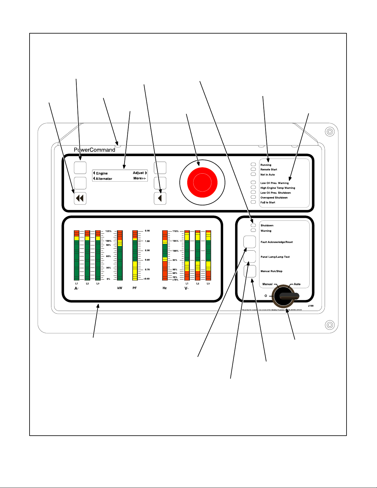
The following describes the function and operation
of the PowerCommand 2100 Control (PCC). All
indicators, control switches/buttons and digital display are located on the face of the control panel as
illustrated in Figure 2-1.
CONTROL PANEL POWER ON/OFF
MODES
The power on/off modes of the control panel and operating software are Power On, Screen Saver and
Sleep/Awake.
Power On Mode: In this mode, power is continuously supplied to the control panel. The control’s
operating software and control panel LEDs/digital
display will remain active until the Screen Saver
mode is activated.
Screen Saver Mode: Power to the digital display is
removed after 30 minutes (generator set not running or running). The 30 minute timer resets and begins after each control panel action (any button or
switch selection) or signal received by the operating
software. All LEDs on the control panel operate normally during Screen Saver mode, indicating that the
operating software is active (Awake mode).
When a “Warning” signal is sensed by the PCC (for
example, low coolant temp), the control displays the
warning message.
Sleep/Awake Mode: In the Sleep mode, the control’s operating software is inactive and the LEDs
and the digital display on the control panel are all off.
Sleep mode is a feature used to reduce battery
power consumption when the control is not being
used and the O/Manual/Auto switch is in the O position.
When all conditions are met (i.e., no unacknowledged faults and O/Manual/Auto switch is in the O
position) the Sleep mode is activated.
The operating software is initialized and the digital
display and control panel LEDs are turned on in response to moving/pressing the following control
panel switch/buttons:
• OManual/Auto switch
• Emergency Stop button
• Fault Acknowledge/Reset button
• Panel Lamp/Lamp Test button
To activate the control and view the menu display
without starting the generator set, press Fault Acknowledge or Panel Lamp button or move mode
switch from O to Manual.
The InPower service tool is required to enable or
disable the Sleep mode. When shipped from the
factory, the Sleep mode is disabled. When disabled,
the operating software will always remain active
(Awake mode). (If network and/or power transfer
control feature is installed, the sleep mode is not
available and should not be enabled − will cause error condition.)
2-1
Page 10
HOME
Redistribution or publication of this document,
by any means, is strictly prohibited.
BUTTON
MENU
SELECTION
BUTTON
(1 of 4)
PANEL
LAMP
(1 of 3)
PREVIOUS
MAIN MENU
BUTTON
DIGITAL
DISPLAY
SHUTDOWN
AND WARNING
STATUS
INDICATORS
EMERGENCY
STOP PUSH
BUTTON
(Pull to reset)
RUNNING/REMOTE
START/NOT IN AUTO
INDICATORS
CONFIGURABLE
INDICATORS
ANALOG AC
METERING
PANEL
(OPTIONAL)
FAULT
ACKNOWLEDGEMENT/
RESET BUTTON
PANEL LAMP
AND LAMP
TEST
BUTTON
FIGURE 2-1. FRONT PANEL
2-2
OFF/MANUAL/
AUTO SWITCH
MANUAL
RUN/STOP
BUTTON
Page 11

FRONT PANEL
Redistribution or publication of this document,
by any means, is strictly prohibited.
Figure 2-1 shows the features of the front panel.
Remote Start Indicator:
This green lamp is lit
whenever the control is receiving a remote start signal.
Digital Display:
This two-line, 20-characters per
line alphanumeric display is used to view menus of
the menu-driven operating system. Refer to the
menu trees later in this section. The display is also
used to show warning and shutdown messages.
Display Menu Selection Buttons:
Four momentary buttons—two on each side of the digital display
window—are used to step through the various
menu options and to adjust generator set parame-
ters. A green triangle (
or ), arrow ( , , , or ),
>>, or plus/minus sign (+ or −) in the digital display
adjacent to the button is shown when the button can
be used (button is “active”). Refer to
And Buttons
Home Button:
later in this section.
Press this button ( ) to view the
Menu Display
Home Menu. Refer to the menu trees later in this
section.
Previous Main Menu Button:
Press this button ( )
to view the previous Main Menu. All main menus include both types of green triangles (
and ). Refer
to the menu trees later in this section.
NOTE: The up and down arrows (
and ) are used
to navigate between submenus.
Emergency Stop Button:
Push this button in for
emergency shutdown of the generator set. This will
stop the generator set immediately and prevent
starting of the set from any location (local and remote).
To reset:
1. Pull the button and allow it to pop out.
2. Turn the O/Manual/Auto switch to O (Off).
3. Press the front panel Fault Acknowledge/Reset button.
4. Select Manual or Auto, as required.
Emergency Stop shutdown can be reset only at the
PCC front panel.
Running Indicator:
This green lamp is lit whenever
the generator (local or remote) is running.
Not in Auto Indicator:
This red lamp flashes continuously when the O/Manual/Auto switch is not in
the Auto position.
Analog AC Metering Panel (Optional):
This panel
simultaneously displays (in percent of genset rated
output):
• 3-phase line-to-line AC current (A~)
• Kilowatts (kW)
• Generator output frequency in hertz (Hz)
• 3-phase line-to-line AC volts (V~)
• Power Factor (PF) (shown in 0.2 increments)
Shutdown Status Indicator:
This red lamp is lit
whenever the control detects a shutdown condition.
The generator set cannot be started when this lamp
is on. After the condition is corrected, shutdown indicators can be reset by turning the O/Manual/Auto
switch to the O position and pressing the Fault Acknowledge/Reset button.
Warning Status Indicator:
This yellow lamp is lit
whenever the control detects a warning condition.
After the condition is corrected, warning indicators
can be reset by pressing the Fault Acknowledge/
Reset button. (It is not necessary to stop the generator set.) In auto mode, warning indicators can also
be reset by cycling the remote reset input after the
condition is corrected.
Some warnings remain active after the condition is
corrected and the control reset button is pressed.
This will require the genset to be shutdown to reset
the warning indicator.
Fault Acknowledge/Reset Button:
Press this button to acknowledge warning and shutdown messages after the fault has been corrected. Pressing
this button clears the fault from the current fault list.
To acknowledge a Warning message, the O/Manual/Auto switch can be in any position. (It is not necessary to stop the generator set to acknowledge an
inactive Warning condition.) To acknowledge a
shutdown message with this button, the O/Manual/
Auto switch must be in the O position.
2-3
Page 12

Panel Lamp and Lamp Test Button:
Redistribution or publication of this document,
by any means, is strictly prohibited.
Press this
button to turn the control panel lamps on or off. The
lights will shut of f after about ten minutes. Press and
hold this button to test all front panel LEDs and meters. The meters will light one bar at a time.
Manual Run/Stop Button:
This button starts and
stops the set locally and will bypass Time Delay to
Start and Stop sequences. The O/Manual/Auto
switch must be in the Manual position to enable this
button.
O/Manual/Auto Switch:
The Manual position en-
ables the use of the Manual Run/Stop button.
The Auto position enables start/stop control of the
engine from a remote location. (It disables the use
of the Manual Run/Stop button.)
The O (Off) position prevents the starting of the set
(local or remote). If the switch is set to O during set
operation, the engine will immediately shut down
(cool-down timers are bypassed). This hot shutdown should be avoided, if possible, to help prolong
the life of the engine.
Configurable Indicators
The following configurable indicators (default values shown) can be changed with the InPower service tool. The configurable items are: change generator event and LED color (green, yellow or red),
and enable/disable indicator.
Low Oil Pressure Warning Indicator:
lamp indicates the oil pressure is lower than the normal range of operation.
High Engine Temperature Warning Indicator:
This yellow lamp indicates the engine temperature
is higher than the normal range of operation.
Low Oil Pressure Shutdown Indicator:
lamp indicates the engine has shut down because
of low oil pressure.
Overspeed Shutdown Indicator:
dicates
speed.
Fail to Start Indicator:
the engine has shut down because of excessive
This red lamp indicates the
engine failed to start.
This yellow
This red
This red lamp in-
2-4
Page 13

MENU DISPLAY AND BUTTONS
Redistribution or publication of this document,
by any means, is strictly prohibited.
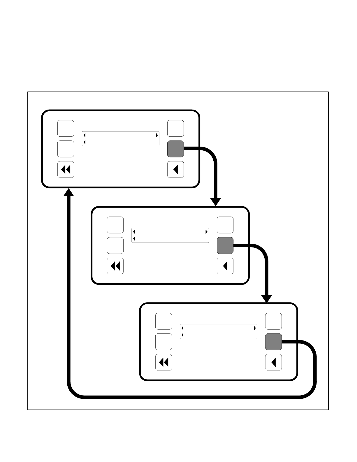
Figure 2-2 shows the digital display and the menu
selection buttons.
Digital Display:
line, digital display is used to view the menus of the
menu-driven operating system. Refer to the menu
trees later in this section. The display is also used to
show fault messages.
Display Menu Selection Buttons:
tary buttons—two on each side of the digital display
window—are used to step through the various
menu options and to adjust generator set parameters. The button is active when a symbol adjacent to
the button is displayed. The displayed symbol indicates the function of the button.
• In the digital display for main menus (Figure
2-3), the
the adjacent button causes the operating pro-
gram to go to the selected submenu (e.g., Engine Menu in Figure 2-5).
The two-line, 20 characters per
Four momen-
and symbols indicate that pressing
• In the digital display, the plus or minus symbols
(+ or −) indicate that pressing the adjacent button can be used to change a parameter or value shown on the display.
When there is a choice of two parameters, one
parameter is associated with the + symbol and
the other is associated with the − symbol.
When changing values, pressing the button a d jacent to the + symbol increase the value and
pressing the button adjacent to the − symbol
decreases the value. Only one numeric character of a field can be changed at a time.
• In the digital display, the
or symbol indicates
that pressing the adjacent button causes the
operating program to move the cursor to the
next numeric character. The selected numeric
character can then be changed by pressing the
buttons adjacent to the + and − symbols. Only
symbol is displayed when the cursor is on
the
the first character of a field that can be
changed. Only the
is displayed when the cursor is on the last character. Both symbols are
displayed when the cursor is on any other character.
• In the digital display, the More>> symbol indicates that pressing the adjacent button causes
the operating program to go to the next main
menu, as shown in Figure 2-3.
• In the digital display, the
or symbols indicate that pressing the adjacent button causes
the operating program to go to the next or previous submenu, as shown in the menu diagrams. Only the
first submenu. Only the
symbol is displayed in the
is displayed in the
last submenu. Both symbols are displayed in
the rest of the submenus.
• After adjusting values/parameters, pressing
the
symbol results in the changes being
saved. If the Home button or Previous Main
Menu button is pressed before pressing the
symbol, the changes are not saved.
Home Button:
Pressing this button causes the operating system to show Main Menu 1 (Figure 2-3) in
the digital display.
Previous Main Menu Button:
Pressing this button
causes the operating system to show the previous
Main Menu in the digital display . All main menus in-
clude both types of green triangles (
and ).
2-5
Page 14

2 LINE, 20 CHARACTERS PER LINE
Redistribution or publication of this document,
by any means, is strictly prohibited.
MENU DISPLAY
DIGITAL DISPLAY
HOME
BUTTON
FIGURE 2-2. DIGITAL DISPLAY AND MENU SELECTION BUTTONS
PREVIOUS MAIN
MENU BUTTON
2-6
Page 15
MAIN MENUS
Redistribution or publication of this document,
by any means, is strictly prohibited.
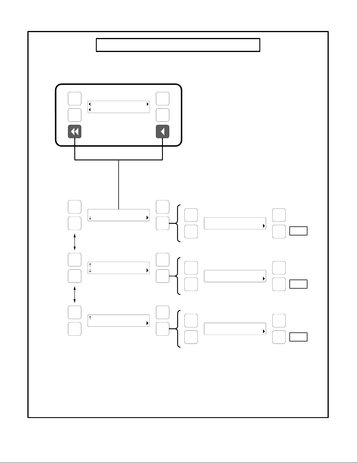
Figure 2-3 shows the three major main menus available to t h e user . Figure 2-3 also includes references
to pages in this section where you can find additional information on submenus. When viewing a submenu, you can press the previous main menu button at any time to view its main menu.
Main Menu 1
As shown in the illustration, each main menu can
branch into one of four directions. Press the button
next to “More>>” in the display to view the next Main
menu. Main Menu 1 is redisplayed when you press
the button next to “More>>” in the Main Menu 3 display.
PAGE
2-11
PAGE
2-13
Engine
Alternator
PAGE
2-17
PAGE
2-19
Adjust
More>>
Main Menu 2
Faults
System
PAGE
NO TAG
History
More>>
PAGE
2-21
Main Menu 3
PAGE
2-23
PAGE
2-25
FIGURE 2-3. MAIN MENUS
About
Pwr Tran
2-7
Setup
More>>
PAGE
5-5
Page 16

CONTROLLER CONFIGURATION MENU
Redistribution or publication of this document,
by any means, is strictly prohibited.
Figure 2-4 shows a block representation of the Controller Configuration menus. These menus are used
to change the default language, temperature units,
and pressure units to be displayed in menus.
To view the first Controller Configuration menu,
make sure Main Menu 1 is displayed and simultaneously press the Home Menu and Previous Main
Menu buttons.
As shown in the diagram, the Controller Configuration menu has three submenus.
Press the button next to the symbol in the display
until the + and − symbols are displayed.
Press the button next to the + or − symbol to select
the desired option.
After selecting option, pressing the
symbol results
in the changes being saved. If the Home button or
Previous Main Menu button is pressed before
pressing the
Language Selected submenu:
symbol, the changes are not saved.
Used to select de-
sired language (default = English).
Temperature Units submenu:
Used to select
Fahrenheit or Centigrade for temperature readings.
Press the buttons next to the
and symbols in the
digital display to navigate between the menus.
Fluid Pressure Units submenu:
PSI or kPA for pressure readings.
Used to select
2-8
Page 17
CONTROLLER CONFIGURATION MENU
Redistribution or publication of this document,
by any means, is strictly prohibited.
Main Menu 1
Engine
Alternator
Language Selected
English
Temperature Units
Deg F
Adjust
More>>
+Language Selected
− English
Back
+Temperature Units
− Deg C
Back
Fluid Pressure Units
PSI
+Fluid Pressure Units
− kPa
FIGURE 2-4. CONTROLLER CONFIGURATION MENU
2-9
Back
Page 18

ENGINE MENU
Redistribution or publication of this document,
by any means, is strictly prohibited.
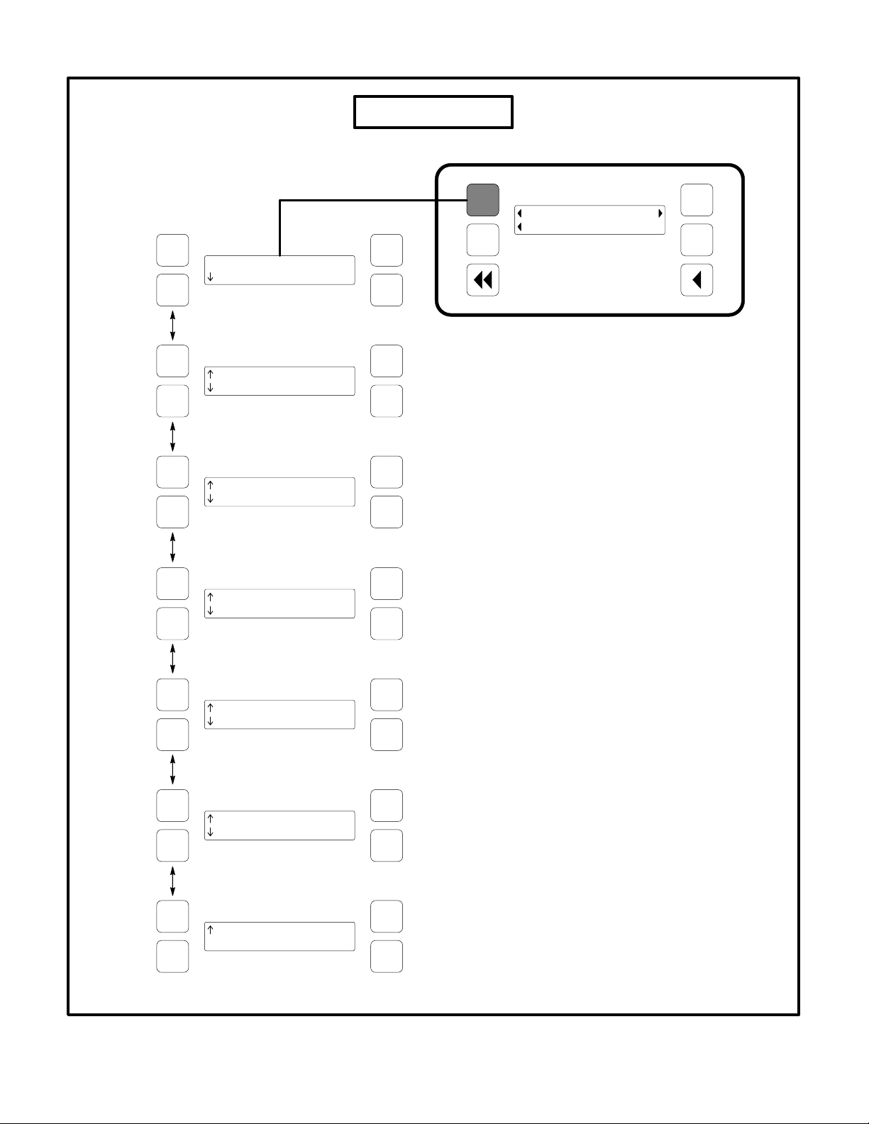
Figure 2-5 shows a block representation of the Engine menu. If you press the button next to the word
“Engine” in the display, the first Engine submenu is
displayed.
As shown in the diagram, the Engine menu has
seven submenus. The data in the submenus will
vary according to the type and number of sensors
provided with the engine.
Press the buttons next to the
digital display to navigate between the menus.
Press the Home button or the Previous Main Menu
button to return to Main Menu 1.
and symbols in the
Coolant Temperature submenu:
This submenu
displays the engine coolant temperature which can
be viewed in degrees Fahrenheit or Centigrade
(see
Controller Configuration Menu
Oil Pressure submenu:
This submenu displays
in this section).
the engine oil pressure which can be viewed in PSI
or kPA (see
Controller Configuration Menu Menu
in
this section).
Oil Temperature submenu:
This submenu displays the engine oil temperature which can be
viewed in degrees Fahrenheit or Centigrade (see
Controller Configuration Menu
Engine Speed submenu:
in this section).
This submenu displays
the engine RPM.
Battery Voltage submenu:
This submenu dis-
plays the engine battery voltage.
Governor Duty Cycle submenu:
This submenu
displays the governor duty cycle (drive) levels in
percentage of maximum.
Active Time Delay submenu:
This submenu displays the time delay that is currently active: warm−
up, cool down, start or stop delays.
2-10
Page 19
ENGINE MENU
Redistribution or publication of this document,
by any means, is strictly prohibited.
Main Menu 1
Coolant Temperature
nnn Deg F
Oil Pressure
nnn PSI
Oil Temperature
nn Deg F
Engine Speed
nnnn RPM
Engine
Alternator
Adjust
More>>
Battery Voltage
nn.n VDC
Governor Duty Cycle
nnn %
Active Time Delay
None nnnn Sec
FIGURE 2-5. ENGINE MENU
2-11
Page 20

ALTERNATOR MENU
Redistribution or publication of this document,
by any means, is strictly prohibited.
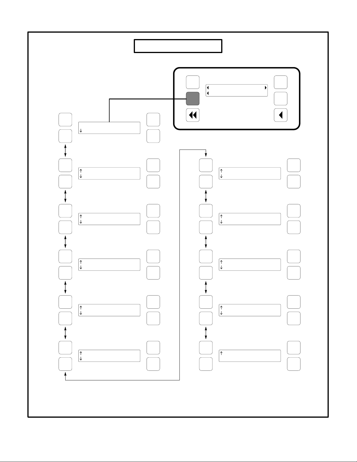
Figure 2-6 shows a block representation of the Alternator menu. If you press the button next to the
word “Alternator” in the display, the first Alternator
submenu is displayed.
As shown in the diagram, the Alternator menu has
eleven submenus.
Press the buttons next to the
digital display to navigate between the menus.
Press the Home button or the Previous Main Menu
button to return to Main Menu 1.
and symbols in the
Line-to-Line V oltage submenu:
The voltage Lineto-Line (L1, L2 and L3) are measured between L1 to
L2, L2 to L3 and L3 to L1, respectively. (Single
phase − L1 to L2 only.)
Line-to-Neutral Voltage submenu:
Note that the
Line-to -Neutral column will not be displayed for a 3
phase/3 wire system. Single phase − L1 to N and L2
to N.
Amps submenu:
All phases. (Single phase − L1
and L2 only.)
Frequency submenu:
Generator set output fre-
quency.
Total Real Power submenu:
This submenu displays the total amount of real power output, in kilowatts (kW).
Real Power submenu:
This submenu displays the
amount of real power output for L1, L2, and L3, in
kilowatts (kW). (Single phase − L1 and L2 only.)
Total Apparent Power submenu:
This submenu
displays the total amount of apparent power output,
in kilovolt amps (kVA).
Apparent Power submenu:
This submenu displays the amount of apparent power output for L1,
L2, and L3, in kilovolt amps (kVA). (Single phase −
L1 and L2 only.)
Total Power Factor submenu:
This submenu displays the power factor with leading/lagging indication.
The PF reading will contain an asterisk if the power
factor is leading (for example, Total PF 0.9 * ).
Power Factor submenu:
This submenu displays a
power factor value for L1, L2, and L3. (Single
phase − L1 and L2 only.)
The PF reading will contain an asterisk if the power
factor is leading (for example, PF L1 0.9*).
AVR Duty Cycle submenu:
This submenu displays the voltage regulator (drive) level in percentage of maximum. (Where maximum is 100% Duty
Cycle, software clamps Duty Cycle maximum to
60% for PMG and 90% for shunt.)
2-12
Page 21
ALTERNATOR MENU
Redistribution or publication of this document,
by any means, is strictly prohibited.
Main Menu 1
Volts L12 L23 L31
V nnn nnn nnn
Volts L1N L2N
V nnn nnn
Amps L1 L2 L3
nnn nnn nnn
Engine
Alternator
Total Power
nn.n kVA
Power L1 L2 L3
kVA nn.n nn.n nn.n
Adjust
More>>
Frequency
nn.n Hz
Total Power
nnn kW
Power L1 L2 L3
kW nn.n nn.n nn.n
Total PF
n.nn*
PF L1 L2 L3
*n.nn *n.nn *n.nn
AVR Duty Cycle
nnn %
FIGURE 2-6. ALTERNATOR MENU
2-13
Page 22

ADJUST MENU
Redistribution or publication of this document,
by any means, is strictly prohibited.
Figure 2-7 shows a block representation of the Adjust menu. If you press the button next to the word
“Adjust” in the display, the first Adjust submenu is
displayed.
As shown in the diagram, the Adjust menu has five
submenus. Each submenu includes a parameter or
value that can be changed.
Press the buttons next to the
digital display to navigate between the menus.
Press the Home button or the Previous Main Menu
button to return to Main Menu 1.
Adjusting Values/Parameters:
and symbols in the
Voltage Adjust submenu:
Voltage can be adjusted to 5 percent of the nominal voltage. For ex-
ample, if genset output voltage is 208 volts, the voltage can be adjusted from 198 to 218 volts.
If the displayed value is greater or less than the allowed (5%) range, the control will not except the
entry and will return to the previous setting. Retry by
entering a smaller change in one volt increments.
Frequency Adjust submenu:
Frequency can be
adjusted to 5 percent of the nominal frequency.
For example, if the genset frequency is 60.0 Hz, the
frequency can be adjusted from 57.0 to 63.0 Hz.
Start Delay submenu:
Start Delay can be set from
0 to 300 seconds (default = 0). This function is bypassed during a manual start/stop sequence.
Stop Delay submenu:
Stop Delay can be set from
0 to 600 seconds (default = 0). This function is bypassed during a manual start/stop sequence and
engine shutdown faults.
1.. Press the button next to the symbol in the display until the + and − symbols are displayed.
2.. If necessary , press the button next to the
or
symbols to move to the numeric character you
wish to change.
3.. Press the button next to the + symbol to increase the value or select parameter; press the
button next to the − symbol to decrease the value or select parameter.
4.. After adjusting values/selecting parameters,
pressing the
symbol results in the changes
being saved. (When adjusting values, make
sure the cursor is on the last numeric character
before pressing the
symbol).
If the Home button or Previous Main Menu button is pressed before pressing the
symbol,
the changes are not saved.
Rated To Idle (Beginning Version 2.303):
Rated
To Idle delay can be set from 0 to 10 seconds (default = 0). (Enter 1 or more to enable.) Entering a
non-zero delay will cause the genset to delay the
transition to Cooldown At Idle.
Idle Start submenu (Not available on all mod-
Idle Start can be enabled or disabled (default =
els):
Disable). This function is only enabled when the
genset is started in manual mode. Idle Start can
also be enabled while the set is running in manual
mode.
Enabling Idle Start will cause the genset to run in
idle mode until Idle Start is disabled. A warning is
displayed if genset is left in idle more than 10 minutes. Long periods of engine idling can eventually
affect engine performance and may void engine
warranty.
The idle speed can be adjusted from 700 to 1100
RPM (default of 800 RPM). Refer to
up Menu
in Section 5. A countdown timer is used to
Crank/Idle Set-
limit engine idle time. With InPower , idle time can be
adjusted from 0 to 60 minutes in 1 minute increments.
2-14
Page 23
ADJUST MENU
Redistribution or publication of this document,
by any means, is strictly prohibited.
Main Menu 1
Voltage Adjust
nnn V
Frequency Adjust
nn.n Hz
Start Delay
nnn Sec
Engine
Alternator
Adjust
More>>
+Voltage Adjust
− nnn V
Back
+Frequency Adjust
− nn.n Hz
Back
+Start Delay
− nnn Sec
Back
Stop Delay
nnn Sec
Rated To Idle Delay
nn Sec
Idle Start
Disable
+Stop Delay
− nnn Sec
Back
+Rated To Idle Delay
− nn Sec
Back
+Idle Start
− Enable
Back
FIGURE 2-7. ADJUST MENU
2-15
Page 24
FAULTS MENU
Redistribution or publication of this document,
by any means, is strictly prohibited.
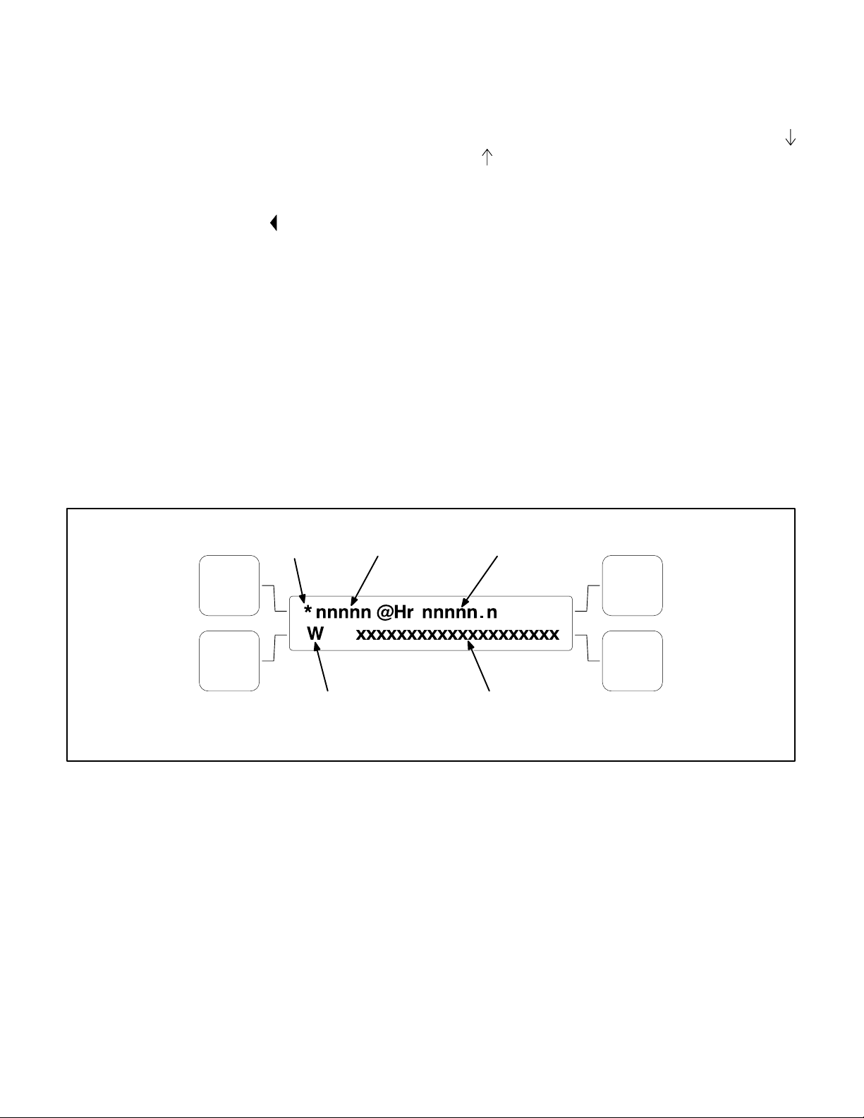
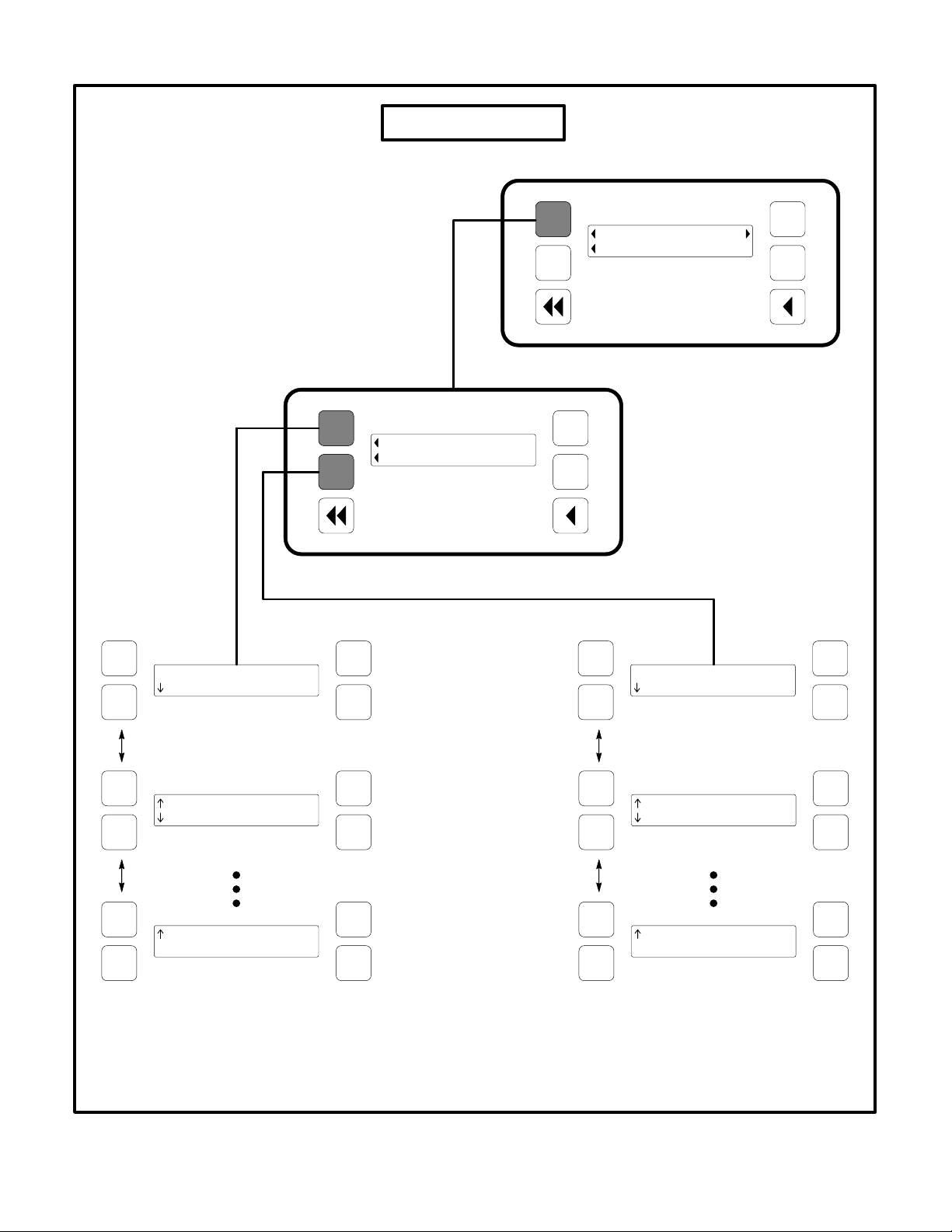
Figure 2-9 shows a block representation of the
Faults menu. Up to 20 of the most recent faults can
be viewed. An example of how a fault code is displayed is shown in Figure 2-8.
The available menus are dependent on the number
of faults that have occurred.
• If there are
word “Faults” is not displayed and no Fault
menus are available.
• If
more than one fault
the button next to the word “Fault” in the
screen display to view the Faults Main Menu.
As shown in the diagram, the Faults Main
Menu has two submenus. Press the Previous
Main Menu button to return to the Faults
Main Menu. Press the Previous Main Menu
button a second time to return to Main
Menu 2.
Press the Home button at any time to return to Main
Menu 1.
no faults
, the symbol next to the
has occurred, press
History submenu:
From the Faults Main Menu,
press the button next to the word “History” in the display to view up to twenty of the most recent ac-
knowledged faults. Press the buttons next to the
and symbols in the digital display to navigate be-
tween the menus. Press the Previous Main Menu
button to return to the Faults Main Menu.
Current Fault submenu:
From the Faults Main
Menu, press the button next to the word “Current” in
the display to view up to twenty of the most recent
unacknowledged faults. Press the Previous Main
Menu button to return to the Faults Main Menu.
ASTERISK =
ACTIVE FAULT
W = WARNING
S = SHUTDOWN
FIGURE 2-8. HISTORY/CURRENT FAULT SUBMENU
FAULT
CODE
HOUR FAULT
OCCURRED
FAULT
DESCRIPTION
2-16
Page 25
FAULTS MENU
Redistribution or publication of this document,
by any means, is strictly prohibited.
Main Menu 2
Faults Main Menu
nnnnn @Hr nnnnn.n
W xxxxxxxxxxxxxxxxxxxx
Fault 1
History
Current
Faults
System
nnnnn @Hr nnnnn.n
S xxxxxxxxxxxxxxxxxxxx
Fault 1
History
More>>
nnnnn @Hr nnnnn.n
S xxxxxxxxxxxxxxxxxxxx
Fault 2
nnnnn @Hr nnnnn.n
W xxxxxxxxxxxxxxxxxxxx
Fault 20
nnnnn @Hr nnnnn.n
W xxxxxxxxxxxxxxxxxxxx
Fault 2
nnnnn @Hr nnnnn.n
W xxxxxxxxxxxxxxxxxxxx
Fault 20
FIGURE 2-9. FAULTS MENU
2-17
Page 26

SYSTEM MENU
Redistribution or publication of this document,
by any means, is strictly prohibited.
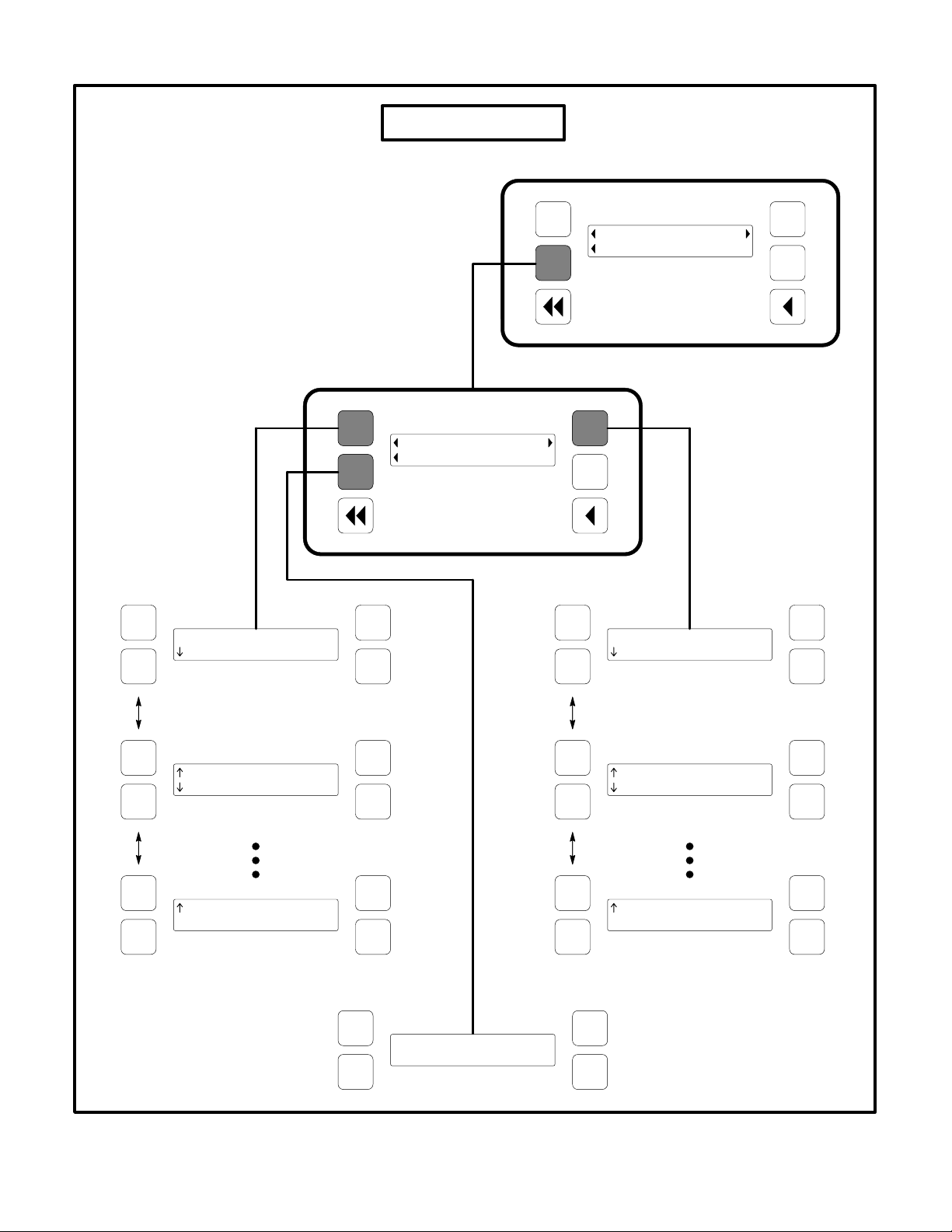
Figure 2-10 shows a block representation of the
System menu. If you press the button next to the
word “System” in the display, the System Main
Menu is displayed. This menu is displayed only if
the network communications module (NCM) feature is installed. The System Main Menu allows you
to view the status and load of other PCC equipment
connected on a common network with the PCC
2100 control.
As shown in the diagram, the System Main Menu
has three submenus.
When viewing ATS and Genset System submenus,
press the buttons next to the
digital display to navigate between the menus.
Press the Previous Main Menu button to return to
the System Main Menu. Press the Previous Main
Menu button a second time to return to Main
Menu 2. Press the Home button to return to Main
Menu 1.
and symbols in the
ATS System submenus:
From the System Main
Menu, press the button next to the word “A TS” in the
display to view the first of up to 16 ATS System submenus. An ATS system must be available in the network to display this submenu.
The ATS submenu allows viewing of the transfer
switch name (configured with InPower), kW load (if
monitored by the ATS system), status (e.g., not in
auto), and source connected and availability (ON =
source connected, OK = source available, or NA =
source not available).
Master System submenu:
From the System Main
Menu, press the button next to the word “Master” in
the display to view the Master System submenu. A
master controller must be available in the network
to display this submenu.
The master submenu allows viewing of the master
controller name (configured with InPower), kW load
and operational state.
Genset System submenus:
From the System
Main Menu, press the button next to the word “Genset” in the display to view the first of up to 16 Genset
System submenus. One genset must be available
in the network to display this submenu.
The genset submenu allows viewing of the genset
name (configured with InPower), kW load and operational state.
If a PCC 2100 control genset, in the network, contains the Power Transfer Control (PTC) feature, a
genset system submenu will be displayed for the
genset and the ATS System submenu will be displayed for the PTC feature.
2-18
Page 27
SYSTEM MENU
Redistribution or publication of this document,
by any means, is strictly prohibited.
Main Menu 2
System Main Menu
ATSnameTag01>nnnnkW
Non Auto S1=On, S2=On
ATS Menu 1
ATS
Master
Genset
Faults
System
GensetName01>nnnnkW
Warning Fail2Start
History
More>>
Genset Menu 1
ATSnameTag02>nnnnkW
NonAut o S1=Ok, S2=NA
ATS Menu 2
ATSnameTag16>nnnnkW
NonAuto S1=Ok, S2=NA
ATS Menu 16
GensetName02>nnnnkW
NonAuto Alarm
Genset Menu 2
GensetName16>nnnnkW
NonAuto Alarm
Genset Menu 16
Master>nnnn kW
Shutdwn N=On,E=NA
FIGURE 2-10. SYSTEM MENU
2-19
Page 28

HISTORY MENU
Redistribution or publication of this document,
by any means, is strictly prohibited.
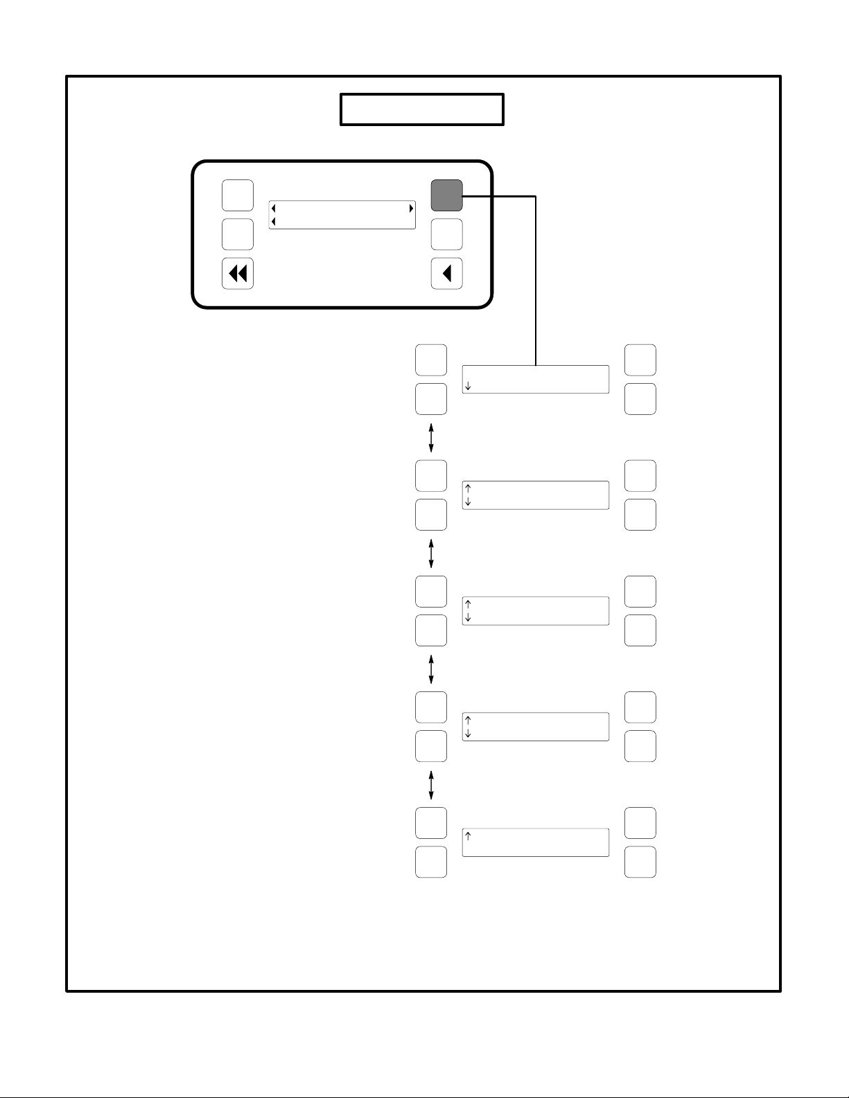
Figure 2-11 shows a block representation of the
History menu. If you press the button next to the
word “History” in the display, the first History submenu is displayed.
Number of Starts submenu:
This submenu shows
the number of engine starts.
Engine Hours submenu:
This submenu shows
the number of operating hours for the engine.
As shown in the diagram, the History menu has five
submenus. This information is stored in non-volatile
memory and will not be deleted due to loss of battery power.
Press the buttons next to the
and symbols in the
digital display to navigate between the menus.
Press the the Previous Main Menu button to return
to Main Menu 2. Press the Home button to return to
Main Menu 1.
Control Hours submenu:
This submenu shows
the number of operating hours for the control.
Kilowatt Hours submenu:
This submenu shows
the number of kilowatt (kW) or megawatt (MW)
hours.
Genset Duty Cycle submenu:
This submenu
shows the percent of genset operating hours that
are less than 30 percent of rated load and percent of
hours that are greater than 90 percent.
2-20
Page 29
HISTORY MENU
Redistribution or publication of this document,
by any means, is strictly prohibited.
Main Menu 2
Faults
System
History
More>>
Number Starts
nnnnn
Engine Hours
nnnnn Hours
Control Hours
nnnnn Hours
kW Hours
nnnnn kW Hrs
Genset Duty Cycle
Hr <30:nn% >90:nn%
FIGURE 2-11. HISTORY MENU
2-21
Page 30

ABOUT MENU
Redistribution or publication of this document,
by any means, is strictly prohibited.
Figure 2-12 shows a block representation of the
About menu. If you press the button next to the word
“About” in the display, the first About submenu is
displayed.
As shown in the diagram, the About menu has three
submenus.
Model submenu:
This submenu shows the genset
model.
Rating submenu:
This submenu shows the rating
(Standby or Prime) and number of kilowatts (kW)).
Press the buttons next to the
and symbols in the
digital display to navigate between the menus.
Press the the Previous Main Menu button to return
to Main Menu 3. Press the Home button to return to
Main Menu 1.
Software Version submenu:
This submenu
shows the software version level. This information
is required to service the generator set.
2-22
Page 31

ABOUT MENU
Redistribution or publication of this document,
by any means, is strictly prohibited.
Main Menu 3
Model
xxxxxxxxxxxxxxx
Rating
Standby nn.n kW
Software Version
nn.nnn
About
Pwr Tran
Setup
More>>
FIGURE 2-12. ABOUT MENU
2-23
Page 32

POWER TRANSFER MENU
Redistribution or publication of this document,
by any means, is strictly prohibited.
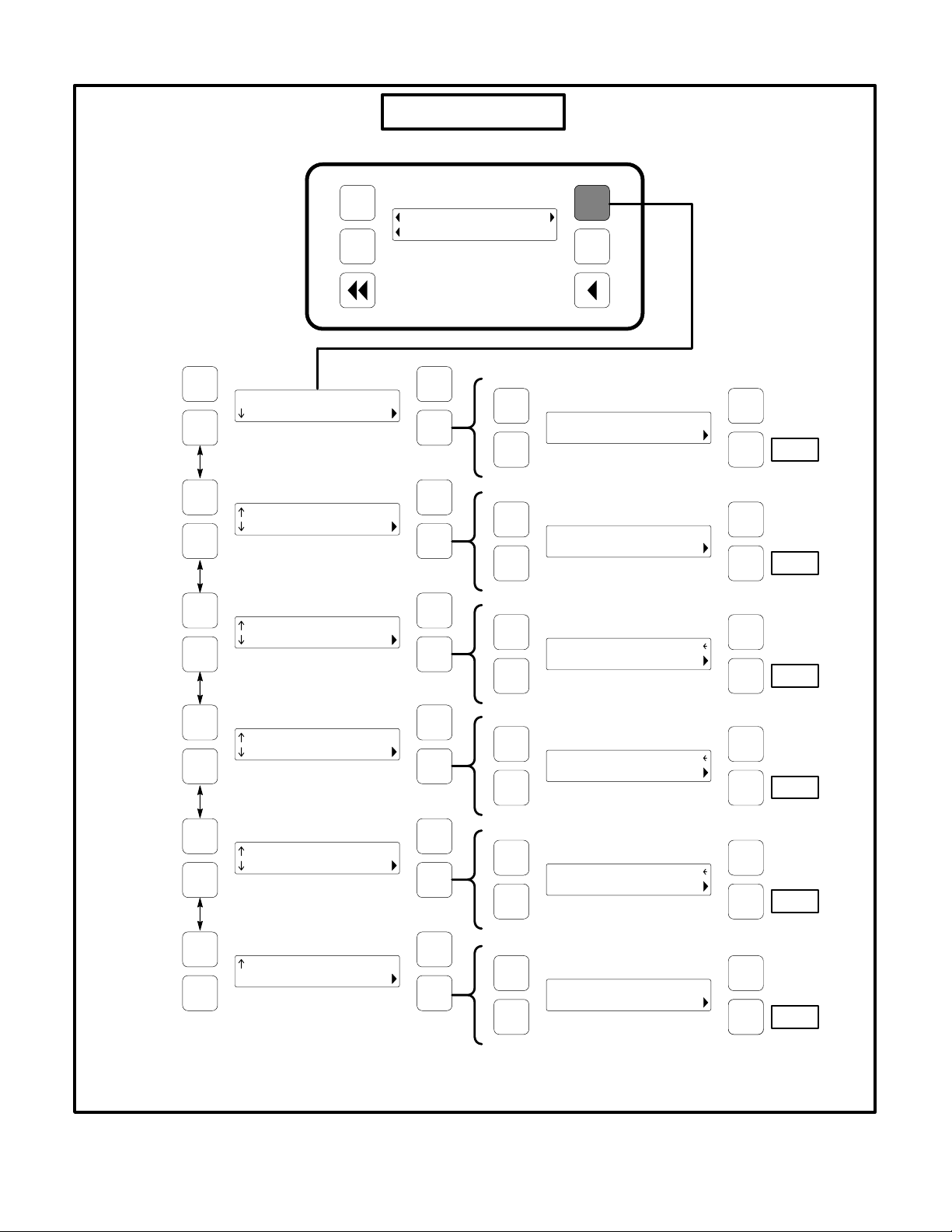
Figure 2-13 shows a block representation of the
Power Transfer menu. If you press the button next
to the word “Pwr Tran” in the display, the first Power
Transfer submenu is displayed. (The Power Transfer Control feature must be installed to display this
submenu.)
With this option installed, the control will monitor the
utility voltage (mains) and frequency for failure. If
power fails, the PTC control will start the generator,
open the mains circuit breakers and close the generator circuit breakers.
S1 (Source 1) submenu:
This submenu shows
power transfer source voltage. The voltages Lineto-Line (L1, L2 and L3) are measured between L1 to
L2, L2 to L3 and L3 to L1, respectively. (Single
phase − L1 to L2 only.)
S1 (L-N Source) submenu:
This submenu is displayed only if the control system is configured for
line−to−neutral voltage sensing of source 1. Single
phase only − L1 to N and L2 to N.
Frequency submenu:
This menu shows power
transfer frequency.
As shown in the diagram, the Power Transfer menu
has five submenus.
Press the buttons next to the
and symbols in the
digital display to navigate between the menus.
Press the the Previous Main Menu button to return
to Main Menu 3. Press the Home button to return to
Main Menu 1.
Source 1 submenu:
This submenu shows utility
status (On, Ok, or NA). “On” means Source 1 is connected and available. “Ok” means Source 1 i s available but not connected. “NA” means Source 1 is not
available.
Genset submenu:
This submenu shows generator
status (On, Ok, or NA). “On” means the genset is
connected and available. “Ok” means the genset is
available but not connected. “NA” means the genset is not available.
Active Transfer Timer submenu:
This submenu
shows the time delay, in seconds.
2-24
Page 33

POWER TRANSFER MENU
Redistribution or publication of this document,
by any means, is strictly prohibited.
Main Menu 3
S1 L12 L23 L31
V nnn nnn nnn
S1 L1N L2N
V nnn nnn
Frequency
nn.n Hz
About
Pwr Tran
Setup
More>>
S1
On
Genset
On
Active Tran Timer
TD Re-Trans nnn Sec
FIGURE 2-13. POWER TRANSFER MENU
2-25
Page 34

THIS PAGE LEFT INTENTIONALLY BLANK
Redistribution or publication of this document,
by any means, is strictly prohibited.
2-26
Page 35

3. Circuit Boards
Redistribution or publication of this document,
by any means, is strictly prohibited.
GENERAL
WARNING
uninsulated parts inside the control panel box
can result in severe personal injury or death.
Measurements and adjustments must be done
with care to avoid touching hazardous voltage
parts.
Stand on a dry wooden platform or rubber insulating mat, make sure your clothing and shoes
are dry, remove jewelry and use tools with insulated handles.
HAZARDOUS VOLTAGE. Touching
INDICATOR
BOARD
DISPLAY
BOARD
This section describes the function of the Power-
Command
2100 Control (PCC) base circuit board
that is contained in the control panel box (Figure
3-1). The block diagram in Figure 3-2, shows the external connections of the PCC system. The system
schematics are provided in
Section 10
of this manu-
al.
CAUTION
Electrostatic discharge will damage
circuit boards. Always wear a grounding wrist
strap when touching or handling circuit boards.
CONTROL
PANEL BOX
BASE
BOARD
FRONT CONTROL
PANEL ASSEMBLY
(MEMBRANE BUTTONS)
BARGRAPH BOARD
(OPTIONAL)
FIGURE 3-1. CIRCUIT BOARD LOCATIONS
3-1
Page 36

Redistribution or publication of this document,
by any means, is strictly prohibited.
FIGURE 3-2. BLOCK DIAGRAM
3-2
Page 37

BASE BOARD
Redistribution or publication of this document,
by any means, is strictly prohibited.
The base circuit board (Figure 3-3) contains all of
the electronic circuitry required to operate the generator set. The Base board provides fuel control
and engine speed governing, main alternator volt-
J6
NCM
J4
DIGITAL DISPLAY
J1
HARNESS
S12, S13
XX = F5 (PCB P/N 300-5381)
RS1 (PCB P/N 327-1379)
age output regulation, and complete generator set
control and monitoring.
The following paragraphs describe each of the connectors (J), fuses (F) and terminal boards (TB)
shown in Figure 3-3.
J2
LED BOARD &
BARGRAPH
J9
InPOWER
J3
MEMBRANE
TB2
PTC
F1 F2 F3
TB1
CUSTOMER CONNECTIONS
FIGURE 3-3. BASE BOARD
XX
F4
F4
J7
ENGINE
J8 − AC
GENERATOR
3-3
Page 38

Connector J1
Redistribution or publication of this document,
by any means, is strictly prohibited.
J1 connects to the Emergency Stop switch (S13)
and the O/Manual/Auto control panel switch (S12).
J1
S13
14
WIRE TABULATION
SIGNAL FROM TO
GND S12-4 J1-8
OFF (O) S12-1 J1-7
MANUAL S12-3 J1-6
AUTO S12-5 J1-5
ESTOP-NC1 S13-1 J1-2
ESTOP-NC2 S13-2 J1-1
ESTOP-NO1 S13-3 J1-3
ESTOP-NO2 S13-4 J1-4
S12
PIN 1
PIN 2
BASE
BOARD
32
EMERGENCY STOP
SWITCH
15
3
4
O/MANUAL/AUTO
SWITCH
FIGURE 3-4. CONNECTOR J1 (CONTROL HARNESS)
3-4
Page 39

Connector J2
Redistribution or publication of this document,
by any means, is strictly prohibited.
J2 connects to LED (indicator) board and bargraph
board of front control panel assembly.
CONNECTOR J2
PIN SIGNAL
1 MOSI
PIN 1
BASE
BOARD
J2
PIN 15
FIGURE 3-5. J2 LED/BARGRAPH CONNECTOR
Connector J3
J3 connects to membrane buttons of front control
panel assembly.
2, 4, 6, 16 GND
3 SCK
5 SEL_A
7 SEL_B
10, 14, 15 VCC
9 SEL_C
11 SEL_D
13 BAR_ENABLE
CONNECTOR J3
PIN SIGNAL
1 HOME MENU <<
2 PREVIOUS MENU <
BASE
BOARD
J3
PIN 10
FIGURE 3-6. J3 MEMBRANE CONNECTOR
3 UPPER LEFT
4 LOWER LEFT
5 UPPER RIGHT
6 LOWER RIGHT
7 FAULT ACK/RESET
8 PANEL LAMP
9 MANUAL RUN/STOP
10 COMMON (GND)
3-5
Page 40

Connector J4
Redistribution or publication of this document,
by any means, is strictly prohibited.
J4 connects to display menu of front control panel
assembly.
PIN 1
BASE
BOARD
J4
PIN 13
FIGURE 3-7. J4 DISPLAY MENU CONNECTOR
CONNECTOR J4
PIN SIGNAL
1 GND
2 VCC
3 N.U.
4 RS
5 R/W
6 ENABLE DISPLAY
7 D[0]
8 D[1]
9 D[2]
10 D[3]
11 D[4]
12 D[5]
13 D[6]
14 D[7]
3-6
Page 41

Connector J7
Redistribution or publication of this document,
by any means, is strictly prohibited.
J7 connects to the engine sensors, battery, starter,
governor actuator and magnetic pickup.
PIN 36
J7
PIN 1
PIN 4
FIGURE 3-8. J7 ENGINE HARNESS CONNECTOR
BASE
BOARD
CONNECTOR J7
PIN SIGNAL
5, 6, 7, 8 GND
1, 2, 3, 4 B+ IN
9
10
11
12
13
17
21
15
16
GEN SW B+
FUEL SOL B−
CT1
CT1−COM
OIL PRE OUT
OIL PRE COM
OIL PRE 5V
CT2
CT2−COM
18 ALT FLASHOUT
19
20
22
26
23
27
24
28
25
29
33
30
34
31
32
35
COOLANT SNDER
COOLANT SNDER COM
CT3
CT3−COM
OIL TEMP
OIL TEMP COM
GEN SW B+
START SOL B−
ACTUATOR +
ACTUATOR −
MAG PICKUP+
MAG PICKUP−
GND
COOL LVL B+
COOL LVL RTN
COOL LVL GND
3-7
Page 42

Connector J8
Redistribution or publication of this document,
by any means, is strictly prohibited.
J8 connects directly to the generator to monitor and
control AC output of the genset.
BASE
BOARD
PIN 24
J8
CONNECTOR J8
PIN SIGNAL COMMENTS
4
12
20
7
13
5
21
22
23
U1 (T1)
V2 (T2)
W3 (T3)
N (T4)
FIELD +
FIELD −
AC2 (PMG2)
AC3 PMG3)
AC4 (PMG4)
Used for alternator
voltage sensing and
power factor angle
sensing
Excitation drive
output
Used for excitation
power (Shunt connection − pins 21 &
22 only)
PIN 1
FIGURE 3-9. J8 AC GENERATOR CONNECTOR
REFERENCE
DESIGNATION
F1 10A Customer B+ (to TB1 customer terminal block)
F2 5A Customer switched B+ (to TB1 customer terminal block)
F3 2A Customer switched B+ (to T26 engine terminal block)
F4 5A Base board power supply fuse
F5 2A B+ supply to Power Transfer Control (PTC) module (optional) (PCB P/N 300-5381)
RS1 (Fuse/Auto
Reset)
PIN 4
TABLE 3-1. BASE BOARD FUSES
RATING FUNCTION
0.9A B+ supply to Power Transfer Control (PTC) module (optional) (PCB P/N 327-1379)
TB1 Customer Connections
Customer monitor/control connections are attached to terminal board TB1. Optional equipment
such as sensing devices used to monitor genset operation, remote start/stop switches and etc. are attached to this terminal. Refer to Customer Connections diagram in
Section 10
for TB1 connections.
TB2 Power Transfer Control (PTC)
Connections
TB2 is used to connect the optional PTC module to
the control. With this option installed, the control will
monitor the utility voltage (mains) and frequency for
failure. If power fails, the PTC control will start the
generator, open the mains circuit breakers and
close the generator circuit breakers. Refer to Customer Connections diagram in
Section 10
connections.
3-8
for TB2
Page 43

4. Troubleshooting
Redistribution or publication of this document,
by any means, is strictly prohibited.
GENERAL
The PowerCommand 2100 Control (PCC) continuously monitors engine sensors for abnormal conditions, such as low oil pressure and high coolant
temperature. If any of these conditions occur, the
PCC will light a yellow Warning lamp or a red Shutdown lamp and display a message on the digital display panel.
INPOWER SERVICE TOOL
The InPower service tool can be used in troubleshooting to perform tests, verify control inputs and
outputs, and test protective functions. Refer to the
InPower User’s Guide, provided with the InPower
software for test procedures.
InPower, when used improperly, can cause symptoms like warnings and shutdowns that appear to be
a defective base board. When these problems occur, always verify that a self-test or fault simulation
(override) have not been left enabled with InPower.
If you do not have InPower, or the enabled fault simulation(s) can not be found using InPower, disconnect battery power to disable the test or override
condition.
Make sure that parameter adjustments and time delays, related to the fault condition, have been appro-
priately set for the application. It may be necessary
to write the initial capture file to the device or update
the calibration file.
Updating a calibration file requires the InPower Pro
version. Confirm that the installed calibration part
number matches the serial plate information.
CAUTION
Using the wrong calibration file can
result in equipment damage. Do not swap Base
boards from another genset model and only use
the calibration file shown on the nameplate.
Some features are not available until the hardware
for that feature is installed and InPower Pro is used
to update (enable) that feature. Confirm that the
feature is installed and enabled prior to troubleshooting the base board for symptoms related to a
feature.
NETWORK APPLICATIONS AND
CUSTOMER INPUTS
In applications with networks and remote customer
inputs, the genset may start unexpectedly or fail to
crank as a result of these inputs. These symptoms
may appear to be caused by the base board. Verify
that the remote input is not causing the symptom or
isolate the control from these inputs before troubleshooting the control.
4-1
Page 44

SAFETY CONSIDERATIONS
Redistribution or publication of this document,
by any means, is strictly prohibited.
WARNING
nents can cause electrocution, resulting in severe personal injury or death. Keep the output
box covers in place during troubleshooting.
Contacting high voltage compo-
CAUTION
Disconnect battery charger from AC
source before disconnecting battery cables.
Otherwise, disconnecting cables can result in
voltage spikes damaging to DC control circuits
of the genset.
High voltages are present when the genset is running. Do not open the generator output box while
the genset is running.
WARNING
Ignition of explosive battery gases
can cause severe personal injury or death. Arcing at battery terminals, light switch or other
equipment, flame, pilot lights and sparks can ignite battery gas. Do not smoke, or switch
trouble light ON or OFF near battery. Discharge
static electricity from body before touching batteries by first touching a grounded metal surface.
Ventilate battery area before working on or near
battery—Wear goggles—Stop genset and disconnect charger before disconnecting battery
cables—Disconnect negative (−) cable first and
reconnect last.
WARNING
Accidental starting of the generator
set can cause severe personal injury or death.
Prevent accidental starting by disconnecting
the negative (−) cable from the battery terminal.
When troubleshooting a generator set that is shut
down, make certain the generator set cannot be accidentally restarted as follows:
1. Move the O/Manual/Auto switch on the control
panel to the O position.
2. Turn off or remove AC power from the battery
charger.
3. Remove the negative (−) battery cable from the
generator set starting battery.
4-2
Page 45

TROUBLESHOOTING PROCEDURE
Redistribution or publication of this document,
by any means, is strictly prohibited.
The following tables are a guide to help you evaluate problems with the generator set. You can save
time if you read through the manual ahead of time
and understand the system.
Try to think through the problem. Go over what was
done during the last service call. The problem could
be as simple as a loose wire, an opened fuse or a
tripped circuit breaker.
NOTE: Each fault code “warning” can be changed to
“shutdown” using InPower. Default settings are
used in this manual. It is recommended that all
changes to settings be recorded at each site to aid in
the troubleshooting of the genset.
This section contains the following information:
• Table 4-1 and 4-2: Describes how to trouble-
shoot a local/remote fail to crank problem when
control panel does not indicate fault condition.
• Table 4-3: Describes each status, warning and
shutdown code, warning and shutdown limits
where applicable, and basic corrective actions,
such as, checking fluid levels, control reset
functions, battery connections, etc.
• Fault Code Tables: Provide detailed trouble-
shooting procedures. In the following tables,
the fault codes are used as the table reference
number and are arranged in numeric order.
Figure 4-2 shows the location of the components
within the control panel that are referenced in the
following troubleshooting procedures. Connector
locations for each circuit board are provided in
tion 3
. The control wiring and circuit board connec-
tions are shown in
CAUTION
Always set the O/Manual/Auto
Section 10
.
switch to the O position before disconnecting
or connecting harness connectors. Otherwise,
disconnecting the harness connectors can result in voltage spikes high enough to damage
the DC control circuits of the set.
CAUTION
Electrostatic discharge will damage
circuit boards. Always wear a wrist strap when
handling circuit boards or when disconnecting
or connecting harness connectors. See Circuit
Board Removal/Replacement in Section 6.
Sec-
4-3
Page 46

EMERGENCY STOP
Redistribution or publication of this document,
by any means, is strictly prohibited.
INDICATOR
BOARD
O/MANUAL/AUTO
SWITCH (S12)
BUTTON
DISPLAY
BOARD
BASE
BOARD
CONTROL ALIVE
INDICATOR
FRONT CONTROL
PANEL ASSEMBLY
(MEMBRANE BUTTONS)
BARGRAPH BOARD
(OPTIONAL)
FIGURE 4-2. PCC CONTROL COMPONENTS
TB2 (1−6) TB1 (1−22)
CHASSIS GROUND
SCREW
AUX RELAYS
(OPTIONAL)
LOCATION
4-4
Page 47

WARNING
Redistribution or publication of this document,
by any means, is strictly prohibited.
Hazards present in troubleshooting can cause equipment damage, severe personal injury
or death. Only trained and experienced service personnel with knowledge of fuels, electricity, and machinery hazards should perform service procedures. Read Safety Precautions page and observe all
instructions and precautions in this manual.
TABLE 4-1. ENGINE DOES NOT CRANK IN MANUAL MODE
(NO FAULT MESSAGE)
Reason: This indicates that the PCC has not received or recognized a manual start signal.
Effect: Engine will not start.
POSSIBLE CAUSE CORRECTIVE ACTION
1. No power supplied to control. (Control
Alive indicator on Base board is not
flashing.)
2. Base board not properly calibrated or
corrupt calibration. (Control Alive indicator flashes every 1/2 second.)
3. The Emergency Stop switch or wiring is
defective.
4. The Manual input is not getting from the
Manual select switch (S12) to the Base
board indicting that S12, Base board or
the harness is bad.
5. The Manual Run/Stop button, harness
or the Base board is bad.
1a. Poor battery cable connections. Clean the battery cable terminals
and tighten all connections.
1b. Remove F4 and check continuity. If open, replace the fuse with one
of the same type and amp rating (5 Amps).
If F4 is OK, remove connector P7 and check for B+ at P7-1 through
P7-4 and GND at P7-5 through P7-8. If B+ or ground missing,isolate to harness and TB BAT terminal mounted on engine block.
If B+ and ground check OK, Base board may be defective. Cycle
power to Base board by reconnecting P7. If Control Alive indicator
does not blink, replace Base board.
2. Confirm that the installed calibration part number matches the serial plate information. Re-enter calibration file if necessary. (When
properly installed, Control Alive indicator flashes every second.)
3. With Emergency Stop push button not activated, remove connector P1 and check for continuity between P1-1 (ESTOP-NC1) and
P1-2 (ESTOP-NC2). (If circuit is open, the control will detect a local
E-Stop condition but will not display the E-Stop condition.) If circuit
is open, isolate to Emergency Stop switch and wiring.
If there is continuity, go to next step.
4. With S12 in Manual, remove connector P1 from the Base board
and check for continuity from P1-6 (MAN) to P1-9 (GND). If no continuity, isolate to switch and wiring.
If there is continuity, go to next step.
5. Remove connector P3 from the Base board and check for continuity from P3-9 (MAN RUN/STOP) to P3-10 (GND). If no continuity
when pressing the Manual Run/Stop button, replace front membrane panel. If there is continuity, the Base board is bad.
4-5
Page 48

WARNING
Redistribution or publication of this document,
by any means, is strictly prohibited.
Hazards present in troubleshooting can cause equipment damage, severe personal injury
or death. Only trained and experienced service personnel with knowledge of fuels, electricity, and machinery hazards should perform service procedures. Read Safety Precautions page and observe all
instructions and precautions in this manual.
TABLE 4-2. ENGINE DOES NOT CRANK IN REMOTE MODE
(NO FAULT MESSAGE)
Reason: This indicates that the PCC has not received or recognized a remote start signal.
Effect: Engine will not start in remote mode, but starts in manual mode.
POSSIBLE CAUSE CORRECTIVE ACTION
1. The remote start switch or customer wiring is faulty.
2. The Auto mode input is not getting from
the Auto select switch (S12) to the Base
board indicting that S12, Base board or
the harness is bad.
1. Reset the control. Attempt to start, and check for ground at TB1-1.
If ground level is not present, isolate to the remote switch or customer wiring. Repair as necessary.
If ground is present, go to next step.
2. With S12 in Auto, remove connector P1 from the Base board and
check for continuity from P1-5 (AUTO) to P1-9 (GND). If no continuity, isolate to switch or wiring harness. If there is continuity, the
Base board is bad.
4-6
Page 49

WARNING
Redistribution or publication of this document,
by any means, is strictly prohibited.
Hazards present in troubleshooting can cause equipment damage, severe personal
injury or death. Only trained and experienced service personnel with knowledge of fuels, electricity, and machinery hazards should perform service procedures. Read Safety Precautions page
and observe all instructions and precautions in this manual.
TABLE 4-3. WARNING AND SHUTDOWN CODES
FAULT CODE CORRECTIVE ACTION
121
SPEED SIGNAL LOST
Lamp: Shutdown
135
OIL PRESSURE SENSOR H
Lamp: Warning
141
OIL PRESSURE SENSOR L
Lamp: Warning
143
PRE-LOW OIL PRES
Lamp: Warning
144
COOL SENSOR HIGH
Lamp: Warning
145
COOL SENSOR LOW
Lamp: Warning
146
PRE-HIGH COOL TMP
Lamp: Warning
Indicates mag pickup speed indication is not being sensed.
Restart and check RPM on the digital display.
Indicates that the control has sensed that the engine oil pressure sender signal is
shorted high. Check sender/connectors/wires.
Indicates that the control has sensed that the engine oil pressure sender signal is
shorted low. Check sender/connectors/wires.
Indicates engine oil pressure has dropped to an unacceptable level. If generator is
powering critical loads and cannot be shut down, wait until next shutdown period
and then follow code 415 procedure.
Indicates that the control has sensed that the engine coolant temperature signal
is shorted high. Check sender/connectors/wires.
Indicates that the control has sensed that the engine coolant temperature signal
is shorted low. Check sender/connectors/wires.
Indicates engine has begun to overheat (coolant temperature has risen to an unacceptable level.
If generator is powering non-critical and critical loads and cannot be shut down,
use the following:
151
HIGH COOLANT TEMP
Lamp: Shutdown
197
LOW COOLANT LEVEL
Lamp: Warning
(Optional)
a. Reduce load if possible by turning off non-critical loads.
b. Check air inlets and outlets and remove any obstructions to airflow.
If engine can be stopped, follow code 151 procedure.
Indicates engine has overheated (coolant temperature has risen above the shut-
down trip point).
Allow engine to cool down completely before proceeding with the following checks:
a. Check coolant level and replenish if low. Look for possible coolant leakage
points and repair if necessary.
b. Check for obstructions to cooling airflow and correct as necessary.
c. Check fan belt and repair or tighten if necessary.
d. Check blower fan and circulation pumps on remote radiator installations.
e. Reset control and restart after locating and correcting problem.
Indicates engine coolant level has fallen below the warning trip point. Allow engine to cool down completely before proceeding.
a. Check coolant level and replenish if low. Look for possible coolant leakage
points and repair if necessary.
b. Reset control and restart after locating and correcting problem.
4-7
Page 50

WARNING
Redistribution or publication of this document,
by any means, is strictly prohibited.
Hazards present in troubleshooting can cause equipment damage, severe personal
injury or death. Only trained and experienced service personnel with knowledge of fuels, electricity, and machinery hazards should perform service procedures. Read Safety Precautions page
and observe all instructions and precautions in this manual.
TABLE 4-3. WARNING AND SHUTDOWN CODES (CONT.)
FAULT CODE CORRECTIVE ACTION
212
OIL TEMP SENSOR H
Lamp: Warning
213
OIL TEMP SENSOR L
Lamp: Warning
234
OVERSPEED
Lamp: Shutdown
235
LOW COOLANT LEVEL
Lamp: Shutdown
359
FAIL TO START
Lamp: Shutdown
415
LOW OIL PRESSURE
Lamp: Shutdown
421
OIL TEMP
Lamp; Warning
(Optional)
Indicates that the control has sensed that the engine oil temperature signal is
shorted high. Check sender/connectors/wires.
Indicates that the control has sensed that the engine oil temperature signal is
shorted low. Check sender/connectors/wires.
Indicates engine has exceeded normal operating speed. Possible causes are
single step large block load removal, flammable vapors drawn into the intake air
passage or turbocharger seals leaking oil.
Indicates engine coolant level has fallen below the shutdown trip point. Allow engine to cool down completely before proceeding.
a. Check coolant level and replenish if low. Look for possible coolant leakage
points and repair if necessary.
b. Reset control and restart after locating and correcting problem.
Indicates possible fuel system problem. (Engine cranks but fails to start)
a. Check for empty fuel tank, fuel leaks, or plugged fuel lines and correct as re-
quired.
b. Check for dirty fuel filter and replace if necessary.
c. Check for dirty or plugged air filter and replace if necessary.
d. Reset the control and restart after correcting the problem.
Indicates engine oil pressure has dropped below the shutdown trip point. Check
oil level, lines and filters. If oil system is OK but oil level is low, replenish. Reset
control and restart.
Indicates engine has begun to overheat (oil temperature has risen to an unacceptable level). If generator is powering non-critical and critical loads and cannot
be shut down, use the following:
a. Reduce load if possible by turning off non-critical loads.
b. Check air inlets and outlets and remove any obstructions to airflow.
If engine can be stopped, follow code 151 procedure and also check engine oil
level.
4-8
Page 51

WARNING
Redistribution or publication of this document,
by any means, is strictly prohibited.
Hazards present in troubleshooting can cause equipment damage, severe personal
injury or death. Only trained and experienced service personnel with knowledge of fuels, electricity, and machinery hazards should perform service procedures. Read Safety Precautions page
and observe all instructions and precautions in this manual.
TABLE 4-3. WARNING AND SHUTDOWN CODES (CONT.)
FAULT CODE CORRECTIVE ACTION
441
LOW BAT VOLTAGE
Lamp: Warning
442
HIGH BAT VOLTAGE
Lamp: Warning
1123
SHUTDOWN AFTER BS
Lamp: Shutdown
1124
DELAYED SHUTDOWN
Lamp: Warning
1131
BATTLE SHORT ACTIVE
Lamp: Warning
Indicates battery voltage supply to the control is approaching a low level at which
unpredictable operation will occur.
a. Discharged or defective battery.
Check the battery charger fuse.
Recharge or replace the battery.
b. Poor battery cable connections. Clean the battery cable terminals and tighten all
connections.
c. Check battery wiring/calibration.
c. Check engine DC alternator. Replace engine DC alternator if normal battery
charging voltage is not obtained.
d. Check battery charge voltage float level if applicable (raise float level).
Indicates battery voltage supply to the control is approaching a high level at which
damage to the control can occur. Check float level on battery charger if applicable
(lower float level). Check battery wiring/calibration.
A shutdown fault occurred while Battle Short was enabled and Battle Short transitioned from enabled to disabled. Review Fault History and perform corrective action.
A shutdown fault became active while the Delayed Shutdown feature was enabled. The shutdown will be delayed by the delayed shutdown time entered. Review Fault History and perform corrective action.
Indicates that the control is in Battle Short mode − used to bypass several critical
fault shutdowns for genset operation during emergencies.
1311, 1312, 1317, 1318
CUSTOMER INPUT #1 − #4
Lamp: Warning/Shutdown or
none for status message.
1313 − 1316
NETWORK FAULT 1 thru 4
Lamp: Warning/Shutdown or
none for status message.
1334
CRIT SCALER OR
Lamp: Shutdown
The nature of the fault is an optional customer selection. Example inputs: Low
Fuel Day Tank, Water In Fuel, Ground Fault, Low Starting Hydraulic Pressure,
Low Starting Air Pressure, etc.
Each of the fault functions can be programmed (using service tool), as follows:
• Enable/disable input (Default: enable)
• Status, Warning or Shutdown (Default: #1−None, #2 thru #4−Warning)
• Active closed or open (Default: closed [ground])
• Change display name using up to 19 characters (Default: #1− Customer Fault 1,
#2−Ground Fault, #3−Low Fuel, #4−Rupture Basin Fault)
Indicates network input (#1−#4) is in an active state.
Each of the fault functions can be programmed (using service tool), as follows:
• Status, Warning or Shutdown
• Change display name using up to 19 characters
Incorrect feature or calibration was entered into control.
4-9
Page 52

WARNING
Redistribution or publication of this document,
by any means, is strictly prohibited.
Hazards present in troubleshooting can cause equipment damage, severe personal
injury or death. Only trained and experienced service personnel with knowledge of fuels, electricity, and machinery hazards should perform service procedures. Read Safety Precautions page
and observe all instructions and precautions in this manual.
TABLE 4-3. WARNING AND SHUTDOWN CODES (CONT.)
FAULT CODE CORRECTIVE ACTION
1335
NONCRIT SCALER OR
Lamp: Warning
1416
FAIL TO SHUTDOWN
Lamp: Warning
1417
POWER DOWN ERROR
Lamp: Warning
1433
EMERGENCY STOP
Lamp: Shutdown
1434
REMOTE E-STOP
Lamp: Shutdown
1435
LOW COOLANT TEMP
Lamp: Warning
Set is not operating. Warning
occurs when engine coolant
temperature is 70° F (21° C)
or lower. NOTE: In applica-
tions where the ambient
temperature falls below 40
F (4° C), Low Coolant Temp
may be indicated even
though the coolant heaters
are operating.
Incorrect feature or calibration was entered into control.
Genset continues to run after receiving shutdown command from the controller.
Battle Short feature enabled − used to bypass several critical fault shutdowns for
genset operation during emergencies.
Indicates that the controller can not power down because of some unknown condition. Possible drain on battery.
Indicates local Emergency Stop. To reset the local/remote Emergency Stop button:
1. Pull the button out.
2. Move the O/Manual/Auto switch to O.
3. Press the front panel Fault Acknowledge/Reset button.
4. Select Manual or Auto, as required.
Indicates remote Emergency Stop. See code 1433 to reset.
Indicates engine coolant heater is not operating or is not circulating coolant.
Check for the following conditions:
a. Coolant heater not connected to power supply. Check for blown fuse or discon-
nected heater cord and correct as required.
b. Check for low coolant level and replenish if required. Look for possible coolant
leakage points and repair as required.
c. Open heater element. Check current draw of heater.
Coolant temperature must be below 70° F (default setting) for one minute to acti-
°
vate warning and be above 70° F for five minutes before the warning can be
cleared.
1438
FAIL TO CRANK
Lamp: Shutdown
1442
WEAK BATTERY
Lamp: Warning
1443
BATTERY FAILED
Lamp: Shutdown
Indicates possible fault with control, speed sensing or starting system.
Indicates that during cranking, the battery voltage is at or below the weak battery
warning trip point for a time greater than or equal to the weak battery set time. See
code 441 for corrective action.
Dead battery − engine will not start. See code 441 for corrective action.
4-10
Page 53

WARNING
Redistribution or publication of this document,
by any means, is strictly prohibited.
Hazards present in troubleshooting can cause equipment damage, severe personal
injury or death. Only trained and experienced service personnel with knowledge of fuels, electricity, and machinery hazards should perform service procedures. Read Safety Precautions page
and observe all instructions and precautions in this manual.
TABLE 4-3. WARNING AND SHUTDOWN CODES (CONT.)
FAULT CODE CORRECTIVE ACTION
1444
KW OVERLOAD
Lamp: Warning
1445
SHORT CIRCUIT
Lamp: Shutdown
1446
HIGH AC VOLTAGE
Lamp: Shutdown
1447
LOW AC VOLTAGE
Lamp: Shutdown
1448
UNDER FREQUENCY
Lamp: Shutdown
1449
OVER FREQUENCY
Lamp: Warning
1452
GEN CB NOT CLOSE
Lamp: Warning
1453
GEN CB NOT OPEN
Lamp: Warning
1459
REVERSE POWER
Lamp: Shutdown
1461
LOSS OF FIELD
Lamp: Shutdown
1466
MODEM FAILURE
Lamp: Warning
1468
NETWORK ERROR
Lamp: Warning
1469
SPEED/HZ MATCH
Lamp: Shutdown
1471
OVER CURRENT
Lamp: Warning
Indicates that generator output power exceeded 105% of genset rating.
Check load and load lead connections.
Indicates that generator output current has exceeded 175% of rated.
Check load and load lead connections. (Fault may not reset for several minutes.)
Indicates that one or more of the phase voltages has exceeded 130% of nominal,
or has exceeded 110% of nominal for 10 seconds.
Indicates that one or more of the phase voltages has dropped below 85% of nominal for 10 seconds.
Indicates that engine speed has dropped below 90% of nominal for 10 seconds.
Check fuel supply, intake air supply and load.
Indicates frequency is 10% above base frequency for 20 seconds.
Refer to Section 5.
Refer to Section 5.
Indicates improper CT phasing. Check wiring to voltage sense circuit. Refer to CT
Installation in
Indicates loss of field (electric) due to reverse kVAR.
Indicates that control can not communicate with the modem. Check for open, short
circuit to ground, and loose connections to the modem.
Indicates momentary loss of communication from the LonWorks Network. Refer to
the LonWorks Network publications for more specific troubleshooting methods.
Indicates that measured speed and measured AC output frequency do not agree.
Check calibration file.
Indicates that generator output current has exceeded 110% of rated for 60 seconds.
Check load and load lead connections.
Section 6
.
4-11
Page 54

WARNING
Redistribution or publication of this document,
by any means, is strictly prohibited.
Hazards present in troubleshooting can cause equipment damage, severe personal
injury or death. Only trained and experienced service personnel with knowledge of fuels, electricity, and machinery hazards should perform service procedures. Read Safety Precautions page
and observe all instructions and precautions in this manual.
TABLE 4-3. WARNING AND SHUTDOWN CODES (CONT.)
FAULT CODE CORRECTIVE ACTION
1472
OVER CURRENT
Lamp: Shutdown
2323 − 2326
NETWORK FAULT 5 thru 8
Lamp: Warning/Shutdown or
none for status message.
2327
PTC FAULT
Lamp: Warning
2329
LOW S1 FREQUENCY
Lamp: Warning
2331
Lamp: Warning
2335
EXCITATION FAULT
Lamp: Shutdown
2336
MEMORY ERROR
Lamp: Shutdown
2337
PWR TRAN DISABLED
Lamp: Warning
2338
PWR TRAN FAILURE
Lamp: Warning
2339
PWR DOWN ENABLED
Lamp: Warning
2341
HIGH CONTROL TEMP
Lamp: Warning
2342
TOO LONG IN IDLE
Lamp: Warning
2358
HIGH S1 VOLTAGE
Lamp: Warning
2396
S1 CB NOT CLOSE
Lamp: Warning
Indicates that generator output current has exceeded 110% of rated, and that a
control time/current calculation has initiated an overcurrent shutdown.
Check load and load lead connections. (Fault may not reset for several minutes.)
Indicates network input (#5−#8) is in an active state. See 1313−1316 fault code
corrective action.
Refer to Section 5.
Refer to Section 5.
Refer to Section 5.
Indicates a loss of all three voltage sense leads or failure in excitation circuit.
Check field wiring (X1 and X2) for shorts or opens.
Indicates control memory error. Data corruption of critical operating parameters.
Try reloading calibration file.
Refer to Section 5.
Refer to Section 5.
Refer to Section 5.
Control temperature is above normal (158° F [70° C]) for a time greater than control temperature set time. Check genset room air flow.
Indicates genset has been in Idle mode too long. Exit idle mode.
Refer to Section 5.
Refer to Section 5.
4-12
Page 55

WARNING
Redistribution or publication of this document,
by any means, is strictly prohibited.
Hazards present in troubleshooting can cause equipment damage, severe personal
injury or death. Only trained and experienced service personnel with knowledge of fuels, electricity, and machinery hazards should perform service procedures. Read Safety Precautions page
and observe all instructions and precautions in this manual.
TABLE 4-3. WARNING AND SHUTDOWN CODES (CONT.)
FAULT CODE CORRECTIVE ACTION
2397
S1 CB NOT OPEN
Lamp: Warning
2966
PTC TIMEOUT
Lamp: Warning
2967
GOVERNOR FAULT
Lamp: Warning
2968
AVR FAULT
Lamp: Warning
2969
LON FAILURE
Lamp: Warning
2971
Lamp: None
2972
FIELD OVERLOAD
Lamp: Shutdown
Refer to Section 5.
Refer to Section 5.
Governor hardware drive circuitry contains a fault condition.
Indicates AVR hardware contains a fault condition.
Indicates no communications with LonWorks board.
Refer to Section 5.
AVR Field has been at Max Field for a time greater than the allowed Max Field
Time.
4-13
Page 56

WARNING
Redistribution or publication of this document,
by any means, is strictly prohibited.
Hazards present in troubleshooting can cause equipment damage, severe personal
injury or death. Only trained and experienced service personnel with knowledge of fuels, electricity, and machinery hazards should perform service procedures. Read Safety Precautions page
and observe all instructions and precautions in this manual.
CODE 121 − SPEED SIGNAL LOST (SHUTDOWN)
Reason: This indicates that the PCC is not sensing the magnetic pickup signal.
Effect: Engine will shut down.
POSSIBLE CAUSE CORRECTIVE ACTION
1. Loose or damaged magnetic pickup
(MPU) wires/connector pins.
2. The magnetic pickup, harness or Base
board could be bad.
1. Inspect the wires/connector pins, and repair or replace as necessary.
2. To isolate the problem, reset the control and attempt to start the set
in Idle mode (select Idle Mode − Enable menu).
a. If 1438 (Fail To Crank) is displayed, or if the engine starts, but then
shuts down on 121 (Speed Signal Lost), the MPU sender could be
bad. Remove the MPU connectors and check for 3.5 to 15 VAC at
the MPU while cranking.
• If no output, check for damage or debris. Also check for improper adjustment of the MPU. (Refer to
still no output, replace the MPU sender.
• If the MPU output is OK, check for MPU voltage at P7−25
(MAG PICK+) to P7-29 (MAG PICK−) while cranking. If OK,
replace the Base board. If not OK, use continuity checks to
isolate connectors/harness.
b. If the engine starts and idles, and does not display a fault, then
there could be a frequency mismatch problem. Measure generator
output frequency with a digital multimeter and compare to the frequency on the PCC display.
• If they do match, multiply the frequency by 30 and compare
this number to the RPM on the PCC display. If these are not
the same, the MPU sender may be bad. Replace the MPU
sender.
• If the multimeter and PCC frequencies do not match, there is a
frequency sensing problem within the Base board. Replace
Base board.
Section 6
.) If there is
4-14
Page 57

WARNING
Redistribution or publication of this document,
by any means, is strictly prohibited.
Hazards present in troubleshooting can cause equipment damage, severe personal
injury or death. Only trained and experienced service personnel with knowledge of fuels, electricity, and machinery hazards should perform service procedures. Read Safety Precautions page
and observe all instructions and precautions in this manual.
CODE 135 − OIL PRESSURE SENSOR HIGH (WARNING)
Reason: This indicates that the engine oil pressure sensor signal is shorted high.
Effect: No engine protection for oil pressure during genset operation.
POSSIBLE CAUSE CORRECTIVE ACTION
1. Fault simulation was enabled with InPower.
2. The sensor connections could be bad. 2. Inspect the sensor and engine harness connector pins. Repair or
3. The sensor could be bad. 3. Disconnect the oil pressure sensor leads, and connect an oil pres-
4. The harness could be bad. 4. Remove connector P7 from Base board and connector from sen-
5. The Base board could be bad. 5. With all connectors attached, check pressure signal (.5 to 4.5 VDC)
1. With InPower, verify that the fault simulation is not enabled for the
oil pressure sensor.
If you do not have InPower, remove battery power from the control
to disable fault simulation overrides.
replace as necessary.
sure sensor simulator to the harness.
“OIL PRESSURE SENSOR H” warning is displayed after the
fault condition is sensed for 10 seconds.
If the control responds to the simulator, replace the sensor. If control does not respond, go to next step.
sor. Check P7-13, 17 & 21 as follows:
• Check for a short circuit from pin to pin (more than 200k ohms
OK).
• Check for an open circuit (10 ohms or less OK).
Repair or replace as necessary.
at P7-13 (OP OUT) and P7-17 (OP COM). If in range, replace Base
board.
4-15
Page 58

WARNING
Redistribution or publication of this document,
by any means, is strictly prohibited.
Hazards present in troubleshooting can cause equipment damage, severe personal
injury or death. Only trained and experienced service personnel with knowledge of fuels, electricity, and machinery hazards should perform service procedures. Read Safety Precautions page
and observe all instructions and precautions in this manual.
CODE 141 − OIL PRESSURE SENSOR LOW (WARNING)
Reason: This indicates that the engine oil pressure sensor signal is shorted low.
Effect: No engine protection for oil pressure during genset operation.
POSSIBLE CAUSE CORRECTIVE ACTION
1. Fault simulation was enabled with InPower.
2. The sensor connections could be bad. 2. Inspect the sensor and engine harness connector pins. Repair or
3. The sensor could be bad. 3. Disconnect the oil pressure sensor leads, and connect an oil pres-
4. The harness could be bad. 4. Remove connector P7 from Base board and connector from sen-
5. The Base board could be bad. 5. With all connectors attached, check pressure signal (.5 to 4.5 VDC)
1. With InPower, verify that the fault simulation is not enabled for the
oil pressure sensor.
If you do not have InPower, remove battery power from the control
to disable fault simulation overrides.
replace as necessary.
sure sensor simulator to the harness.
“OIL PRESSURE SENSOR L” warning is displayed after the
fault condition is sensed for 10 seconds.
If the control responds to the simulator, replace the sensor. If control does not respond, go to next step.
sor. Check P7-13, 17 & 21 as follows:
• Check for an open circuit (10 ohms or less OK).
• Check for a short circuit to the engine block ground (more than
200k ohms OK).
• Check for a short circuit from pin to pin (more than 200k ohms
OK).
Repair or replace as necessary.
at P7-13 (OP OUT) and P7-17 (OP COM). If in range, replace Base
board.
4-16
Page 59

WARNING
Redistribution or publication of this document,
by any means, is strictly prohibited.
Hazards present in troubleshooting can cause equipment damage, severe personal
injury or death. Only trained and experienced service personnel with knowledge of fuels, electricity, and machinery hazards should perform service procedures. Read Safety Precautions page
and observe all instructions and precautions in this manual.
CODE 143/415 − PRE-LOW OR LOW OIL PRESSURE (WARNING/SHUTDOWN)
Reason: Engine oil pressure has dropped below the warning/shutdown threshold for low/high oil pressure.
Effect: Calibration-dependent. No action is taken by the PCC for code 143. Engine will shut down for code 415.
POSSIBLE CAUSE CORRECTIVE ACTION
1. Fault simulation was enabled with InPower.
2. Low oil level. Clogged lines or filters. 2. Check oil level, lines and filters. If oil system is OK but oil level is
3. Sensor or oil pump could be bad. Or the
generator set may be shutting down on
another fault.
4. Harness or Base board could be bad. 4. If the control does not respond to the simulator, the Base board or
1. With InPower, verify that the fault simulation is not enabled for the
oil pressure sensor.
If you do not have InPower, remove battery power from the control
to disable fault simulation overrides.
low, replenish.
3. Disconnect the oil pressure sensor leads, and connect an oil pressure sensor simulator to the harness.
a. If the control responds to the simulator, reconnect the sensor, dis-
connect the ACT− signal wire at the fuel pump actuator, and crank
the engine. Check the oil pressure reading on the digital display.
• If the display shows an acceptable oil pressure, the problem
may not be in the oil or oil sensing system. The genset may be
shutting down on another fault (out of fuel, intermittent connector). Restart the genset and monitor the PCC display panel for other faults.
• If the display does not show an acceptable oil pressure, replace the sensor. If the PCC still doesn’t display an oil pressure while cranking, the oil pump may be bad. Refer to the engine service manual.
If the control does not respond to the simulator, go to next step.
the harness is bad.
Check for +5 VDC at the sensor (lead marked E1-A). If there is no 5
VDC at the sensor:
• Check for 5 VDC at P7-21.
• If yes, harness is bad. If no, Base board is bad.
If there is 5 VDC at the sensor, use the sensor simulator to generate
a signal to P7-13 (OP OUT) and P7-17 (OP COMM). If the pressure
signal (.5 to 4.5 VDC) does not get to P7, isolate to the harness. If
the pressure signal does go to P7, the Base board is bad.
4-17
Page 60

WARNING
Redistribution or publication of this document,
by any means, is strictly prohibited.
Hazards present in troubleshooting can cause equipment damage, severe personal
injury or death. Only trained and experienced service personnel with knowledge of fuels, electricity, and machinery hazards should perform service procedures. Read Safety Precautions page
and observe all instructions and precautions in this manual.
CODE 144 − COOLANT SENSOR HIGH (WARNING)
Reason: This indicates that the coolant temperature sensor signal is shorted high.
Effect: No engine protection for coolant temperature during genset operation. Possible white smoke.
POSSIBLE CAUSE CORRECTIVE ACTION
1. Fault simulation was enabled with InPower.
2. The sensor connections could be bad. 2. Inspect the sensor and engine harness connector pins. Repair or
3. The sensor could be bad. 3. Disconnect the sensor, and plug in a resistive sensor simulator to
4. The harness or Base board could be
bad.
1. With InPower, verify that the fault simulation is not enabled for the
coolant sensor.
If you do not have InPower, remove battery power from the control
to disable fault simulation overrides.
replace as necessary.
isolate the fault.
If the control responds to the simulator, replace the sensor. If con-
trol does not respond, go to next step.
4. Measure the resistance of the coolant sensor and reconnect harness to sensor. Remove connector P7 from Base board and check
resistance between pins P7-30 (IH20) and P7-34 (IH20 COM).
• If resistance is not the same, harness is bad.
• If resistance is the same, Base board is bad.
4-18
Page 61

WARNING
Redistribution or publication of this document,
by any means, is strictly prohibited.
Hazards present in troubleshooting can cause equipment damage, severe personal
injury or death. Only trained and experienced service personnel with knowledge of fuels, electricity, and machinery hazards should perform service procedures. Read Safety Precautions page
and observe all instructions and precautions in this manual.
CODE 145 − COOLANT SENSOR LOW (WARNING)
Reason: This indicates that the coolant temperature sensor signal is shorted low.
Effect: No engine protection for coolant temperature during genset operation. Possible white smoke.
POSSIBLE CAUSE CORRECTIVE ACTION
1. Fault simulation was enabled with InPower.
2. The sensor connections could be bad. 2. Inspect the sensor and engine harness connector pins. Repair or
3. The sensor could be bad. 3. Disconnect the sensor, and plug in a resistive sensor simulator to
4. The harness or Base board could be
bad.
1. With InPower, verify that the fault simulation is not enabled for the
coolant sensor.
If you do not have InPower, remove battery power from the control
to disable fault simulation overrides.
replace as necessary.
isolate the fault.
If the control responds to the simulator, replace the sensor. If con-
trol does not respond, go to next step.
4a. Remove connector P7 from Base board and disconnect sensor.
Check pins P7-30 (IH20) and P7-34 (IH20 COM) for short circuit as
follows:
• Check for a short circuit to the engine block ground (more than
200k ohms OK).
• Check for a short circuit from pin to pin (more than 200k ohms
OK).
Repair or replace as necessary.
4b. Measure the resistance of the coolant sensor and reconnect har-
ness to sensor. Remove connector P7 from Base board and check
resistance between pins P7-30 (IH20) and P7-34 (IH20 COM).
• If resistance is not the same, harness is bad.
• If resistance is the same, Base board is bad.
4-19
Page 62

WARNING
Redistribution or publication of this document,
by any means, is strictly prohibited.
Hazards present in troubleshooting can cause equipment damage, severe personal
injury or death. Only trained and experienced service personnel with knowledge of fuels, electricity, and machinery hazards should perform service procedures. Read Safety Precautions page
and observe all instructions and precautions in this manual.
CODE 146/151 − PRE-HIGH OR HIGH COOLANT TEMPERATURE (WARNING/SHUTDOWN)
Reason: Engine coolant temperature has exceeded the warning threshold for pre-high/high coolant temperature.
Effect: Calibration-dependent. No action is taken by the PCC for code 146. Engine will shut down for code 151.
POSSIBLE CAUSE CORRECTIVE ACTION
1. Fault simulation was enabled with InPower.
2. Engine or sensor circuitry problem. 2. Isolate to the engine or sensor circuitry.
3. The sensor could be bad. 3. Disconnect the sensor and connect a coolant temperature sensor
4. The harness or Base board could be
bad.
1. With InPower, verify that the fault simulation is not enabled for the
coolant sensor.
If you do not have InPower, remove battery power from the control
to disable fault simulation overrides.
Check the sensor accuracy with a thermocouple or similar temperature probe.
• If the PCC ambient coolant temperature reading is accurate,
the engine may be overheating. Refer to the engine service
manual.
• If the PCC ambient coolant temperature reading is not accurate, go to next step.
simulator to the harness.
If the control responds to the simulator, replace the sensor. If con-
trol does not respond, go to next step.
4. Measure the resistance of the coolant sensor and reconnect harness to sensor. Remove connector P7 from Base board and check
resistance between pins P7-30 (IH20) and P7-34 (IH20 COM).
• If resistance is not the same, harness is bad.
• If resistance is the same, Base board is bad.
4-20
Page 63

WARNING
Redistribution or publication of this document,
by any means, is strictly prohibited.
Hazards present in troubleshooting can cause equipment damage, severe personal
injury or death. Only trained and experienced service personnel with knowledge of fuels, electricity, and machinery hazards should perform service procedures. Read Safety Precautions page
and observe all instructions and precautions in this manual.
CODE 197/235 − LOW COOLANT LEVEL (WARNING/SHUTDOWN)
Reason: Engine coolant level has dropped below the warning/shutdown threshold for low/high coolant level.
Effect: No action is taken by the PCC for code 197. Engine will shut down for code 235.
POSSIBLE CAUSE CORRECTIVE ACTION
The sensor, harness or Base board could be
bad.
If the coolant level is normal, isolate the source of the low coolant signal.
(This is a ground signal.)
Disconnect the signal lead at the sender and reset the control.
1. If the 197/235 message drops out and does not reappear, replace
the sender.
2. If the 197/235 message reappears and remains after control reset,
remove connector P7 from Base board and check continuity from
P7-32 to ground.
• If there is continuity, replace the harness.
• If there is not continuity, replace the Base board.
CODE 212 − OIL TEMPERATURE SENSOR HIGH (WARNING)
Reason: This indicates that the oil temperature sensor signal is shorted high.
Effect: No engine protection for oil temperature during genset operation. No effect on performance.
POSSIBLE CAUSE CORRECTIVE ACTION
1. The sensor connections could be bad. 1. Inspect the sensor and engine harness connector pins. Repair or
replace as necessary.
2. The sensor could be bad. 2. Disconnect the sensor, and plug in the simulator to isolate the fault.
If the control responds to the simulator, replace the sensor. If con-
trol does not respond, go to next step.
3. The the harness or Base board could be
bad.
3. Measure the resistance of the oil sensor and reconnect harness to
sensor. Remove connector P7 from Base board and check resistance between pins P7-22 (OIL TEMP) and P7-26 (OIL TEMP
COM).
• If resistance is not the same, harness is bad.
• If resistance is the same, Base board is bad.
4-21
Page 64

WARNING
Redistribution or publication of this document,
by any means, is strictly prohibited.
Hazards present in troubleshooting can cause equipment damage, severe personal
injury or death. Only trained and experienced service personnel with knowledge of fuels, electricity, and machinery hazards should perform service procedures. Read Safety Precautions page
and observe all instructions and precautions in this manual.
CODE 213 − OIL TEMPERATURE SENSOR LOW (WARNING)
Reason: This indicates that the oil temperature sensor signal is shorted low.
Effect: No engine protection for oil temperature during genset operation. No effect on performance.
POSSIBLE CAUSE CORRECTIVE ACTION
1. The sensor connections could be bad. 1. Inspect the sensor and engine harness connector pins. Repair or
replace as necessary.
2. The sensor could be bad. 2. Disconnect the sensor, and plug in the simulator to isolate the fault.
If the control responds to the simulator, replace the sensor. If con-
trol does not respond, go to next step.
3. The harness or Base board could be
bad.
3a. Remove connector P7 from Base board and disconnect sensor.
Check pins P7-22 (OIL TEMP) and P7-26 (OIL TEMP COM) for
short circuit as follows:
• Check for a short circuit to the engine block ground (more than
200k ohms OK).
• Check for a short circuit from pin to pin (more than 200k ohms
OK).
Repair or replace as necessary.
3b. Measure the resistance of the coolant sensor and reconnect har-
ness to sensor. Remove connector P7 from Base board and check
resistance between pins P7-22 (OIL TEMP) and P7-26 (OIL TEMP
COM).
• If resistance is not the same, harness is bad.
• If resistance is the same, Base board is bad.
4-22
Page 65

WARNING
Redistribution or publication of this document,
by any means, is strictly prohibited.
Hazards present in troubleshooting can cause equipment damage, severe personal
injury or death. Only trained and experienced service personnel with knowledge of fuels, electricity, and machinery hazards should perform service procedures. Read Safety Precautions page
and observe all instructions and precautions in this manual.
CODE 234 − OVERSPEED (SHUTDOWN)
Reason: Engine speed signal indicates an engine speed greater than shutdown threshold.
Effect: Engine will shut down.
POSSIBLE CAUSE CORRECTIVE ACTION
1. Cold engine (no coolant heaters) 1. Overspeed can occur when starting a vary cold engine. Clear fault
and restart genset.
2. Single step large block load removal. 2. Clear fault and restart genset.
1. Fault simulation was enabled with In-
Power.
2. Fault threshold is not set correctly with
InPower.
3. Monitor the engine rpm using InPower. 3. If the RPM is not correct, refer to fault code 121 for corrective ac-
4. The electronic governor actuator could
be bad.
1. With InPower, verify that the fault simulation is not enabled for the
coolant sensor.
If you do not have InPower, remove battery power from the control
to disable fault simulation overrides.
2. Reset the threshold to the highest allowable setting. Determine the
required operating range before adjusting the threshold.
tion.
4. Binding in actuator assembly of injection pump. Disassembly of injection pump may be required to inspect/repair O-rings, pump, etc.
Refer to the engine service manual.
CODE 235 − LOW COOLANT LEVEL (SHUTDOWN)
Reason:
Effect:
POSSIBLE CAUSE CORRECTIVE ACTION
1. Refer to code 197. 1. Refer to code 197.
4-23
Page 66

WARNING
Redistribution or publication of this document,
by any means, is strictly prohibited.
Hazards present in troubleshooting can cause equipment damage, severe personal
injury or death. Only trained and experienced service personnel with knowledge of fuels, electricity, and machinery hazards should perform service procedures. Read Safety Precautions page
and observe all instructions and precautions in this manual.
CODE 359 − FAIL TO START (SHUTDOWN)
Reason: This indicates that the engine failed to start after expiration of last crank time.
Effect: Engine will not start.
POSSIBLE CAUSE CORRECTIVE ACTION
1. Restricted fuel supply due to:
a. Fuel level below pickup tube in
tank.
b. Closed shutoff valve in supply line.
c. Fuel injectors clogged.
d. Air in fuel system.
2. Fuel solenoid not energized due to:
a. Fuse F1 o f harness assembly may
be opened.
b. Fuse F3 on Base board may be
open.
c. Base board is bad.
d. K1 Fuel Pilot Relay is bad.
e. Fuel solenoid is bad.
1a. Add fuel if low. Prime the fuel system.
1b. Open any closed shutoff valve in the fuel line supplying the engine.
1c. Refer to engine service manual.
1d. Bleed air from fuel system. Refer to engine service manual.
Isolate to F1, F3, K1 relay, fuel solenoid or Base board.
2a. Remove fuse F1 (located near TB BATT terminal on engine block)
and check continuity. If open, replace the fuse with one of the same
type and amp rating (3 Amps.) If fuse reopens, check wiring continuity of fuel solenoid circuit/test fuel solenoid. (Go to step 2e for solenoid test.)
2b. Remove fuse F3 (located on Base board) and check continuity. If
open, replace the fuse with one of the same type and amp rating (2
Amps.) If fuse reopens, check wiring continuity/test K12 fuel pilot
relay coil.
2c. Install harness tool between Base board P7 connector. Attempt to
start and check for B+ at P9-9 (GEN SW B+) and P7-10 (FUEL
SOL−). (These are the leads to the K1 coil.)
• If there is no B+, the Base board is bad.
• If there is B+, K1 or the harness is bad. Go to step 2d.
2d. Attempt to start and check for B+ IN (K1-30) and OUT (K1-87)
• If there is no B+ IN, check for open circuit.
• If There is B+ IN and not OUT, K1 is bad.
• If there is B+ OU T, fuel solenoid or the harness is bad. Check
circuit between K1-87 and fuel solenoid. Repair as necessary.
If OK, go to step 2e.
2e. Disconnect lead to fuel solenoid. Measure the resistance of the fuel
solenoid between fuel solenoid terminal and the engine block. A
reading of 30 ohms indicates that the solenoid coil is OK.
If coil resistance is OK, check mechanical operation of solenoid by
connecting B+ to solenoid terminal. Solenoid should click when energized.
4-24
Page 67

WARNING
Redistribution or publication of this document,
by any means, is strictly prohibited.
Hazards present in troubleshooting can cause equipment damage, severe personal
injury or death. Only trained and experienced service personnel with knowledge of fuels, electricity, and machinery hazards should perform service procedures. Read Safety Precautions page
and observe all instructions and precautions in this manual.
CODE 359 − FAIL TO START (SHUTDOWN)(CONT.)
Reason: This indicates that the engine failed to start after expiration of last crank time.
Effect: Engine will not start.
POSSIBLE CAUSE CORRECTIVE ACTION
3. Injection pump actuator not energized
due to the harness, governor actuator or
the Base board is bad.
Isolate to harness, governor actuator or Base board.
3a. Display “Governor Duty Cycle” menu. Attempt to start and check
for duty cycle (44% is about average). If percentage of duty cycle is
displayed before shutdown, the harness, actuator or output circuit
of Base board is bad, go to step 3b. (Duty cycle displayed indicates
processor is functioning, but output circuitry of Base board could
still be defective.) If the duty cycle is not displayed, the Base board
is bad.
3b. Remove connector P7 from Base board and check wiring continu-
ity of actuator circuit. P7-24 (ACT +) and P7-28 (ACT −) to appropriate +/− terminals of governor actuator. Repair as necessary. If continuity is OK, go to step 3c.
3c. Disconnect the two leads attached to the injection pump actuator.
Measure the resistance across the two actuator terminals. A reading of 7.5 ohms indicates that the actuator circuit is OK. (This test
only shows that the actuator circuit is not opened or shorted, but not
if there is binding.) Replace actuator assembly if open or short is
measured. If actuator is OK, go to step 3d.
3d. Attempt to start and check for CNTL B+ at terminal lead ACT + of
governor actuator (use engine block for meter ground). If not present, Base board is bad.
If CNTL B+ is present, attempt to start and check for GOV PWM
(pulse width modulated) signal (measure across terminals of actuator). If not present, Base board is bad.
If GOV PWM signal is present, governor actuator is bad (binding in
actuator assembly of injection pump). Disassembly of injection
pump may be required to inspect/repair O-rings, pump, etc. (Refer
to engine service manual.)
4-25
Page 68

WARNING
Redistribution or publication of this document,
by any means, is strictly prohibited.
Hazards present in troubleshooting can cause equipment damage, severe personal
injury or death. Only trained and experienced service personnel with knowledge of fuels, electricity, and machinery hazards should perform service procedures. Read Safety Precautions page
and observe all instructions and precautions in this manual.
CODE 415 − LOW OIL PRESSURE (SHUTDOWN)
Reason: Engine oil pressure has dropped below the shutdown threshold for high oil pressure.
Effect: Engine will shut down.
POSSIBLE CAUSE CORRECTIVE ACTION
1. Refer to code 143. 1. Refer to code 143.
CODE 421 − OIL TEMPERATURE (WARNING)
Reason: Engine oil temperature has exceeded the warning threshold for high oil temperature.
Effect: No action is taken by the PCC. Possible loss of performance.
POSSIBLE CAUSE CORRECTIVE ACTION
1. Fault threshold is not set correctly with
InPower.
2. Engine or sensor circuitry problem. 2. Isolate to the engine or sensor circuitry.
3. The sensor could be bad. 3. Disconnect the sensor and connect an oil temperature sensor sim-
4. The harness or Base board could be
bad.
1. Reset the threshold to the highest allowable setting. Determine the
required operating range before adjusting the threshold.
Check the sensor accuracy with a thermocouple or similar temperature probe.
• If the PCC ambient oil temperature reading is accurate, the
engine may be overheating. Refer to the engine service
manual.
• If the PCC ambient oil temperature reading is not accurate, go
to next step.
ulator to the harness.
If the control responds to the simulator, replace the sensor. If con-
trol does not respond, go to next step.
4. Measure the resistance of the oil sensor and reconnect harness to
sensor. Remove connector P7 from Base board and check resistance between pins P7-22 (OIL TEMP) and P7-26 (OIL TEMP
COM).
• If resistance is not the same, harness is bad.
• If resistance is the same, Base board is bad.
4-26
Page 69

WARNING
Redistribution or publication of this document,
by any means, is strictly prohibited.
Hazards present in troubleshooting can cause equipment damage, severe personal
injury or death. Only trained and experienced service personnel with knowledge of fuels, electricity, and machinery hazards should perform service procedures. Read Safety Precautions page
and observe all instructions and precautions in this manual.
CODE 441 − LOW BATTERY VOLTAGE (WARNING)
Reason: Low voltage has been detected for battery.
Effect: PCC voltage supply approaching level at which unpredictable operation may occur.
POSSIBLE CAUSE CORRECTIVE ACTION
1. Weak or discharged battery. 1. Recharge or replace the battery. Specific gravity for a fully charged
battery is approximately 1.260 at 80° F (27° C).
2. Low electrolyte level in battery. 2. Replenish electrolyte and recharge battery.
3. Battery connections loose or dirty. 3. Clean and tighten or replace the battery cable connectors and
cables at the battery and the set.
4. Wrong battery voltage. 4. Verify that battery voltage 12 or 24 matches calibration.
5. Insufficient battery charging voltage. 5. Adjust charge rate of battery charging circuit, according to
manufactures instructions.
6. Engine DC alternator could be bad. 6. Replace engine DC alternator if normal battery charging voltage
(12 to 14 or 24 to 26 VDC) is not obtained.
7. If the batteries are OK, the problem may
be the harness or the Base board.
7. Remove connector P7 from Base board and check battery voltage
at P7−3 (B+) to P7-7 (GND) and P7−4 (B+) to P7-8 (GND).
• If the voltage at P7 is not the same as the battery voltage, the
harness is bad.
• If the voltage at P7 is OK, the Base board is bad.
CODE 442 − HIGH BATTERY VOLTAGE (WARNING)
Reason: High voltage has been detected for battery.
Effect: PCC damage will occur.
POSSIBLE CAUSE CORRECTIVE ACTION
1. Excessive battery charging voltage. 1. Adjust charge rate of battery charging circuit according to
manufacturers instructions.
2. Engine DC alternator could be bad. 2. Replace engine DC alternator if normal battery charging voltage
(12 to 14 or 24 to 26 VDC) is not obtained.
3. Wrong battery voltage. 3. Verify that battery voltage 12 or 24 matches calibration.
4-27
Page 70

WARNING
Redistribution or publication of this document,
by any means, is strictly prohibited.
Hazards present in troubleshooting can cause equipment damage, severe personal
injury or death. Only trained and experienced service personnel with knowledge of fuels, electricity, and machinery hazards should perform service procedures. Read Safety Precautions page
and observe all instructions and precautions in this manual.
CODE 1311, 1312, 1317, 1318 − CUSTOMER INPUT (WARNING/SHUTDOWN)
Reason: The nature of the fault is an optional customer selection.
Effect: Status, warning or shutdown.
POSSIBLE CAUSE CORRECTIVE ACTION
If there is no actual fault, the problem may be
an external wiring problem, active input
(closed or open) selection is incorrect.
Disconnect the signal lead from TB1 and reset the control.
• CUST_IN1 − TB1-4
• CUST_IN2 − TB1-5
• CUST_IN3 − TB1-6
• CUST_IN4 − TB1-7
If the message drops out, the external wiring has a short or open circuit,
or the active input selection (closed/open) is not correct for customer input (use service tool to check selection).
4-28
Page 71

WARNING
Redistribution or publication of this document,
by any means, is strictly prohibited.
Hazards present in troubleshooting can cause equipment damage, severe personal
injury or death. Only trained and experienced service personnel with knowledge of fuels, electricity, and machinery hazards should perform service procedures. Read Safety Precautions page
and observe all instructions and precautions in this manual.
CODE 1435 − LOW COOLANT TEMPERATURE (WARNING)
Reason: Engine coolant temperature has dropped below the warning threshold for low coolant temperature.
Effect: No action is taken by the PCC. Engine may not start due to slow cranking speed.
POSSIBLE CAUSE CORRECTIVE ACTION
1. Fault simulation was enabled with InPower.
2. Fault threshold is not set correctly with
InPower.
3. The engine coolant heater could be bad.
(Radiant heat should be felt with hand
held close to outlet hose.)
4. The sensor connections could be bad. 4. Inspect the sensor and engine harness connector pins. Repair or
5. The sensor could be bad. 5. Disconnect the sensor, and plug in a resistive sensor simulator to
6. The harness or Base board could be
bad.
1. With InPower, verify that the fault simulation is not enabled for the
coolant sensor.
If you do not have InPower, remove battery power from the control
to disable fault simulation overrides.
2. Reset the threshold to the lowest allowable setting. Determine the
required operating range before adjusting the threshold.
3. Coolant heater not operating due to:
• Coolant heater not connected to power. Check for blown fuse,
or disconnected heater cord and correct as required.
• Low coolant level. Look for possible coolant leakage points
and repair as required.
• Defective heater element/thermostat. With coolant heater removed from engine and power disconnected, flush with cold
tap water for two minutes to close internal heater thermostat
(opens at 100
across input power leads:
a. Open − replace coolant heater.
b. Closed − coolant heater OK (coil resistance of 10 to 60
replace as necessary.
isolate the fault.
If the control responds to the simulator, replace the sensor. If con-
trol does not respond, harness or Base board is bad.
6. Measure the resistance of the coolant temperature sensor and reconnect harness to sensor. Remove connector P7 from Base
board and check resistance between pins P7-30 (IH20) and P7-34
(IH20 COM).
• If resistance is not the same, harness is bad.
• If resistance is the same, Base board is bad.
° F and closes at 80° F). Check resistance
ohms)
4-29
Page 72

WARNING
Redistribution or publication of this document,
by any means, is strictly prohibited.
Hazards present in troubleshooting can cause equipment damage, severe personal
injury or death. Only trained and experienced service personnel with knowledge of fuels, electricity, and machinery hazards should perform service procedures. Read Safety Precautions page
and observe all instructions and precautions in this manual.
CODE 1438 − FAIL TO CRANK (SHUTDOWN) (LOCAL OR REMOTE)
Reason: This indicates that the engine failed to crank after the PCC received a start signal.
Effect: Engine will not start.
POSSIBLE CAUSE CORRECTIVE ACTION
1. Starter is bad. 1. Reset the control. Attempt to start, and test for B+ at the starter. If
there is B+ a t the starter, the starter could be bad. Test starter (see
engine service manual). Replace the starter.
If B+ is not present at the starter, go to next step.
2. Base board is bad or fuse F3 on the
Base board may be open.
3. Start Pilot Relay K4 or starter circuitry
could be bad.
4. The Emergency Stop switch or wiring is
defective.
5. MPU/circuit is bad. 5. Refer to Code 121 instructions.
2. Remove F3 and check continuity. If open, replace the fuse with one
of the same type and amp rating (2 Amps).
If F3 is OK, install harness tool between Base board P7 connector.
Attempt to start and check for B+ at P7-23 (GEN SW B+) and P7-27
(START SOL−). (These are leads to the K4 coil.)
• If there is no B+ signal, the Base board is bad.
• If there is a B+ signal, the Start Pilot Relay K4 or starter circuit-
ry is bad. Go to next step.
3. Check for B+ IN at K4-1 (directly connected to battery B+). If not
present, check for open circuit.
If there is B+ IN, attempt to start and test for B+ OUT at K4-4.
• If there is no B+ OUT at K4-4, K4 is bad.
• If there is B+ OUT at K4-4, check for open circuit between
K4-4 and starter.
4. With Emergency Stop push button not activated, remove connector P1 and check for continuity between P1-1 (ESTOP-NC1) and
P1-2 (ESTOP-NC2). (If circuit is open, the control will detect a local
E-Stop condition but will not display the E-Stop condition.) If circuit
is open, isolate to Emergency Stop switch and wiring.
If there is continuity, go to next step.
4-30
Page 73

WARNING
Redistribution or publication of this document,
by any means, is strictly prohibited.
Hazards present in troubleshooting can cause equipment damage, severe personal
injury or death. Only trained and experienced service personnel with knowledge of fuels, electricity, and machinery hazards should perform service procedures. Read Safety Precautions page
and observe all instructions and precautions in this manual.
CODE 1442 − WEAK BATTERY (WARNING)
Reason: Battery is weak.
Effect: No action is taken by the PCC.
POSSIBLE CAUSE CORRECTIVE ACTION
1. Weak or discharged battery. 1. Recharge or replace the battery. Specific gravity for a fully charged
battery is approximately 1.260 at 80° F (27° C).
2. Low electrolyte level in battery. 2. Replenish electrolyte and recharge battery.
3. Battery connections loose or dirty. 3. Clean and tighten or replace the battery cable connectors and
cables at the battery and the set.
4. Insufficient battery charging voltage. 4. Adjust charge rate of battery charging circuit, according to
manufacturers instructions.
5. If the batteries are OK, the problem may
be the harness.
5. Remove connector P7 from Base board. Check battery voltage at:
P7-3 (CNTL) to P7-7 (GND) and
P7-4 (CNTL) to P7-8 (GND)
If voltage is not OK, repair defective harness.
CODE 1443 − BATTERY FAILED (SHUTDOWN)
Reason: Battery is dead.
Effect: Engine will not start.
POSSIBLE CAUSE CORRECTIVE ACTION
1. Refer to code 1438. 1. Refer to code 1438 instructions.
4-31
Page 74

WARNING
Redistribution or publication of this document,
by any means, is strictly prohibited.
Hazards present in troubleshooting can cause equipment damage, severe personal
injury or death. Only trained and experienced service personnel with knowledge of fuels, electricity, and machinery hazards should perform service procedures. Read Safety Precautions page
and observe all instructions and precautions in this manual.
CODE 1444 − KW OVERLOAD (WARNING)
Reason: The kW has reached overload. The threshold for kW overload is 3 seconds at 110 percent of rated power
output.
Effect: No action taken by the PCC.
POSSIBLE CAUSE CORRECTIVE ACTION
1. Fault threshold is not set correctly with
InPower.
2. Short or overload. 2. Check the load and load cables. Repair if necessary. Check opera-
3. Incorrect CTs or CT connections. 3. Check CTs and CT connections. Correct if necessary. Refer to
4. The problem may be the Base board or
harness connections.
1. Reset the threshold to the highest allowable setting. Determine the
required operating range before adjusting the threshold.
tion by disconnecting load and restarting generator set.
rent Transformer Installation
4. Remove connector P7 from Base board. Check continuity from P7
to CTs.
P7-11 (CT1) to P7-12 (CT1-COM)
P7-15 (CT2) to P7-16 (CT2-COM)
P7-19 (CT3) to P7-20 (CT3-COM)
Repair connections.
in
Section 6
.
CODE 1445 − SHORT CIRCUIT (SHUTDOWN)
Reason: This indicates that the generator output current has exceeded 175% of rated.
Effect: Engine will shut down.
POSSIBLE CAUSE CORRECTIVE ACTION
1. Refer to code 1444. 1. Refer to code 1444.
Cur-
CODE 1471/1472 − OVER CURRENT (WARNING/SHUTDOWN)
Reason: This indicates that the generator output current has exceeded 110% of rated.
Effect: No action is taken by the PCC for code 1471. Engine will shut down for code 1472.
POSSIBLE CAUSE CORRECTIVE ACTION
1. Refer to code 1444. 1. Refer to code 1444.
4-32
Page 75

WARNING
Redistribution or publication of this document,
by any means, is strictly prohibited.
Hazards present in troubleshooting can cause equipment damage, severe personal
injury or death. Only trained and experienced service personnel with knowledge of fuels, electricity, and machinery hazards should perform service procedures. Read Safety Precautions page
and observe all instructions and precautions in this manual.
CODE 1446 − HIGH AC VOLTAGE (SHUTDOWN)
Reason: One or more of the phase voltages has exceeded 130% of nominal, or has exceeded 110% of nominal for
10 seconds.
Effect: Engine will shut down.
POSSIBLE CAUSE CORRECTIVE ACTION
1. Fault simulation was enabled with InPower.
2. Single step large block load removal. 2. Clear fault and restart genset.
3. Fault threshold is not set correctly with
InPower.
4. Base board or generator is bad. 4. Refer to
1. With InPower, verify that the related fault simulation is not enabled.
If you do not have InPower, remove battery power from the control
to disable fault simulation overrides.
3. Reset the threshold to the highest allowable setting. Determine the
required operating range before adjusting the threshold.
Generator/Base Board Isolation Procedure
determine if the generator or the Base board is causing the high A C
voltage shutdown fault.
in
Section 7
to
4-33
Page 76

WARNING
Redistribution or publication of this document,
by any means, is strictly prohibited.
Hazards present in troubleshooting can cause equipment damage, severe personal
injury or death. Only trained and experienced service personnel with knowledge of fuels, electricity, and machinery hazards should perform service procedures. Read Safety Precautions page
and observe all instructions and precautions in this manual.
CODE 1447 − LOW AC VOLTAGE (SHUTDOWN)
Reason: One or more of the phase voltages has dropped below 85% of nominal for 10 seconds.
Effect: Engine will shut down.
POSSIBLE CAUSE CORRECTIVE ACTION
1. Fault simulation was enabled with InPower.
2. Fault threshold is not set correctly with
InPower.
3. Overload. 3. Check the load and correct any overload. Check operation by dis-
4. Improper connections have been made
at the generator output terminals.
5. PMG or field wiring could be bad. 5. Check and repair the PMG or field wiring (
6. Shunt wiring connection could be incorrect.
7. The rotating rectifier assembly (diodes
CR1 through CR6) is faulty.
8. Loose connector or Base board is bad. 8. Repair connections (P8) or replace the Base board if necessary.
1. With InPower, verify that the related fault simulation is not enabled.
If you do not have InPower, remove battery power from the control
to disable fault simulation overrides.
2. Reset the threshold to the lowest allowable setting. Determine the
required operating range before adjusting the threshold.
connecting load and restarting generator set.
4. Reconnect according to the appropriate reconnection diagram.
See
Section 10
6. Check that excitation inputs P8-21 and P8-22 are connected to the
correct voltage. If misconnected to a high voltage, the AVR fault will
shut down excitation and cause Low AC Voltage condition. (
Section 10
7. Check each diode (
.
refer to Section 10
).
refer to
).
refer to Section 7
).
Reason: Generator AC output frequency is low.
Effect: Generator set will shut down.
POSSIBLE CAUSE CORRECTIVE ACTION
1. Fault simulation was enabled with InPower.
2. Fault threshold is not set correctly with
InPower.
3. Overload. 3. Check the load and correct any overload. Check operation by dis-
4. Fuel or air delivery problem. 4. Refer to the engine service manual.
5. Loose connector or Base board is bad. 5. Repair connections (P8) or replace the Base board if necessary.
CODE 1448 − UNDER FREQUENCY (SHUTDOWN)
1. With InPower, verify that the related fault simulation is not enabled.
If you do not have InPower, remove battery power from the control
to disable fault simulation overrides.
2. Reset the threshold to the lowest allowable setting. Determine the
required operating range before adjusting the threshold.
connecting load and restarting generator set.
4-34
Page 77

WARNING
Redistribution or publication of this document,
by any means, is strictly prohibited.
Hazards present in troubleshooting can cause equipment damage, severe personal
injury or death. Only trained and experienced service personnel with knowledge of fuels, electricity, and machinery hazards should perform service procedures. Read Safety Precautions page
and observe all instructions and precautions in this manual.
CODE 1449 − OVER FREQUENCY (WARNING)
Reason: Generator AC output frequency is high.
Effect: No action taken by the PCC.
POSSIBLE CAUSE CORRECTIVE ACTION
1. Fault simulation was enabled with InPower.
2. Fault threshold is not set correctly with
InPower.
3. Fuel or air delivery problem. 3. Refer to the engine service manual.
4. Loose connector or Base board is bad. 4. Repair connections (P7/P8) or replace the Base board if neces-
1. With InPower, verify that the related fault simulation is not enabled.
If you do not have InPower, remove battery power from the control
to disable fault simulation overrides.
2. Reset the threshold to the highest allowable setting. Determine the
required operating range before adjusting the threshold.
sary.
4-35
Page 78

THIS PAGE LEFT INTENTIONALLY BLANK
Redistribution or publication of this document,
by any means, is strictly prohibited.
4-36
Page 79

5. PTC Troubleshooting
Redistribution or publication of this document,
by any means, is strictly prohibited.
GENERAL
This section describes the optional Power Transfer
Control (PTC module) and the related Fault Codes
and troubleshooting procedures.
The PTC troubleshooting procedures use fault
codes, from the PCC 2100 diagnostics, and symptoms. Conditional schematics are used with the
symptoms to help diagnose problems, including
those not covered by the fault codes.
WARNING
Improper operation of the generator
set presents a hazard that can cause severe personal injury or death. Observe all safety precautions in your generator set manuals.
WARNING
AC power at the PTC Module or at
the breakers or contactors present a shock hazard that can cause severe personal injury or
death. Use extreme caution to avoid touching
electrical contacts with body, tools, jewelry,
hair, clothes, etc. Remove power from both
source 1 and source 2 before removing and replacing components. The following procedures
are to be performed only by technically qualified personnel.
PTC MODULE
cluding the genset start signal and network port),
the RS-232 communications port for the service
tool, and drivers for the control panel indicators,
switches, and meters.
Utility voltage is monitored by the PCC 2100 control
via voltage sensing transformers on the PTC module. The PTC module contains relays that are used
to drive external relays (K20 thru K23) to perform
the transfer function.
Two versions of the PTC module are available
based on the application voltage. Four optional external power relays are also required. The relays
must be selected based on the power rating of the
switching mechanism (circuit breaker or contactor),
coil voltage and mounting type. Refer to the PTC kit
instructions for relay selection.
SEQUENCE OF EVENTS
The control executes a prescribed sequence of
events for all PTC operations. The genset must set
to the Auto position for the following sequence of
events to occur. The operations for a typical loss of
S1 utility power and a return of S1 utility power are:
Transfer from Source 1 (Utility) to Source
2 (Genset)
The optional PTC module is used to transfer the
customer load between Source 1 (S1 utility) and
Source 2 (S2 genset) as needed in the event that
the utility power is unstable. The PTC module measures source 1 (Utility) voltage and frequency. The
value of S1 voltage and frequency is monitored by
the base board where the PCC 2100 control determines if the voltage and frequency are within limits.
The system, controlled by the PCC 2100, attempts
to maintain a power source for the customer load.
The PCC 2100 actively performs monitoring and
control of the power source to the customer load.
The PCC 2100 contains the logic and timing circuits
that control the transfer sequence. This control also
contains many of the customer interface circuits (in-
This sequence of events includes a programmed
transition and begins with Source 1 (utility) available and connected. The sequence ends with
Source 2 (generator) assuming the load. (See Figure 2.)
1. Source 1 fails. The control senses that Source
1 voltage and frequency are not within the specified limits with the under-voltage, over-voltage, or frequency.
2. Source 1 (Utility) is no longer within specified
limits (high or low voltage, or low frequency).
3. The control initiates an engine start time delay
(TDES), that delays engine start up for
Source 2.
5-1
Page 80

4. If TDES expires without a return to acceptable
Redistribution or publication of this document,
by any means, is strictly prohibited.
Source 1 power, the control energizes the K4
genset start pilot relay.
5. As soon as the control senses that the generator output reaches 90% (ready to load), it initiates a Transfer Time Delay (Source 1 to
Source 2 transfer) to give the genset time to
stabilize. The transfer time delay counts down.
6. When the transfer time delay expires, the control momentarily energizes the K22 Open Utility
Relay. The K22 relay contacts close energizing
S1-1, the S1 Open Coil. The S1 breaker (or
contactor) opens and the S1-3 auxiliary contact
opens to indicate that S1 is open.
7. The control verifies that the Source 1 breaker
(or contactor) is open.
10. Source 1 is restored and within specified voltage and frequency limits.
11. The control senses when Source 1 output is
within the specified voltage and frequency limits. The status changes to Source 1
Available
.
Utility
12. The control initiates a Retransfer Time Delay
(Source 2 to Source 1) to give Source 1 time
to stabilize. The Retransfer time counts down.
13. When the Retransfer time expires, the control
momentarily energizes the K20 Open Genset
Relay. The K20 relay contacts close energizing
S1-2, the S2 Open Coil. The S2 breaker (or
contactor) opens and the S2-3 contacts opens
to indicate that S2 is open.
8. The control initiates a programmed transition
time delay (or recharge delay), so that residual
voltage from an inductive load can decay. The
delay counts down.
9. When the delay expires, the control momentarily energizes K21, the Close Genset Relay.
K21 contacts close energizing S2-2, the S2
Close Coil. The S2 breaker (or contactor)
closes and the S2-3 contacts close to indicate
that S2 is closed. The generator assumes the
load. The status changes to
Genset
Con-
nected.
Transfer from Source 2 to Source 1
This sequence of events includes a programmed
transition and begins with Source 2 (generator)
available and connected. The sequence ends with
Source 1 assuming the load and the generator cooling down.
14. The control verifies that the Source 2 breaker
(or contactor) is open.
15. The control initiates programmed transition
time delay (or recharge delay), so that residual
voltage from an inductive load can decay. The
delay time counts down.
16. When the delay expires, the control momentarily energizes K23, the Close Utility Relay.
K23 contacts close, energizing S2-1, the S1
Close Coil. The S1 breaker (or contactor)
closes and the S1-3 contacts close to indicate
that S1 is closed. The utiltiy assumes the load.
The status changes to
S1 (Utility)
Connected.
17. The control initiates a TDEC (time delay, engine cool-down) to allow the engine to cool
down under no load conditions. When the time
delay ends the engine shuts down.
5-2
Page 81

TROUBLESHOOTING USING FAULT
Redistribution or publication of this document,
by any means, is strictly prohibited.
CODES
TABLE 5-1. PTC FAULT CODES AND MESSAGES
The Digital Display shows only fault events (warnings and shutdowns). The last 20 faults can be
viewed with the Digital Display. You can also read
the events in the event history file by using the PC
Service Tool.
Fault Events
1452 Genset CB Not Closed
1453 Genset CB Not Open
2327 PTC Fault
2329 Low S1 Frequency
2331 Low S1 Voltage
2337 PWR Tran Disabled
Fault events should be considered alarms for the
genset operator. They indicate that one of the power sources or the PTC is not operating correctly.
2338 PWR Tran Failure
2339 PWR Down Enabled
Table 5-1 lists the fault codes and fault message
and Table 5-2 gives corrective actions for each fault
code.
The controller displays the fault message on the
Digital Display and flashes the asterisk indicator.
2358 High S1 Voltage
2396 S1 CB Not Close
2397 S1 CB Not Open
2966 PTC Timeout
Y ou must press the Reset button on the control panel to acknowledge a fault and clear the display.
TABLE 5-2. PTC FAULT CODE TROUBLESHOOTING
WARNING
Some PTC service procedures present hazards that can result in severe person-
2971 No message (PTC Test Mode Active)
al injury or death. Only qualified service personnel with knowledge of electricity and machinery
hazards should perform service. See Safety Precautions.
GENSET CB NOT CLOSED (1452)
The genset circuit breaker (S2) failed to close when PTC is enabled.
Corrective Action:
1. Refer to Toubleshooting Chart 5-4 for a listing of all the possible causes.
GENSET CB NOT OPEN (1453)
The genset circuit breaker (S2) failed to open when PTC is enabled.
Corrective Action:
1. Refer to Toubleshooting Chart 5-5 for a listing of all the possible causes.
5-3
Page 82

TABLE 5-2. PTC FAULT CODE TROUBLESHOOTING (CONT.)
Redistribution or publication of this document,
by any means, is strictly prohibited.
WARNING
Some PTC service procedures present hazards that can result in severe personal injury or death. Only qualified service personnel with knowledge of electricity and machinery
hazards should perform service. See Safety Precautions.
PTC FAULT (2327)
The PTC module or the communication link to the PTC module is not working properly
when PTC is enabled.
Corrective Action:
1. Check for blinking light on the PTC module to indicate that it has power (Figure 5-1). If off, check for
B+ between TB3-3 and TB3-4. Check PTC status voltage between TB3-5 and TB3-6, 0.2 VDC, if
not present, see steps 2 and 3.
2. Check to make sure cable ground shield, on the cable from the PTC module is properly grounded
at the PCC2100.
3. Repower the PCC2100 control to see if fault clears. (Remove power from the control for 5 seconds,
then repower).
LOW S1 FREQUENCY (2329)
Low utility (S1) frequency.
Corrective Action:
1. Check S1 AC inputs and wiring to PTC at TB5.
2. Check sensor set points at PCC 2100 control.
LOW S1 VOLTAGE (2331)
Low utility (S1) voltage.
Corrective Action:
1. Utility (S1) low voltage. This is a common fault at initial startup due to a delay in sending the S1 voltage status from the PTC module, via the network connection, to the control. Clear the fault and it
should not reoccur until the next S1 failure.
1. Check S1 AC inputs and wiring to PTC at TB5.
2. Check S1 pickup and dropout set points at PCC 2100 control.
POWER TRAN DISABLED (2337)
The PTC module is available, but the PTC feature is not enabled.
Corrective Action:
1. Use the InPower service tool to enable the PTC feature. After enabling the feature, cycle power off
at the control for 5 seconds, then repower control.
5-4
Page 83

TABLE 5-2. PTC FAULT CODE TROUBLESHOOTING (CONT.)
Redistribution or publication of this document,
by any means, is strictly prohibited.
WARNING
Some PTC service procedures present hazards that can result in severe personal injury or death. Only qualified service personnel with knowledge of electricity and machinery
hazards should perform service. See Safety Precautions.
POWER TRAN FAILURE (2338)
The PTC module trim is enabled, but the control could not communicate with the PTC module.
Corrective Action:
1. PTC module does not have power or is not installed. Check for blinking light on the PTC module to
indicate that it has power (Figure 5−1). If off, check for B+ between TB3-3 and TB3-4. Check PTC
status voltage between TB3-5 and TB3-6, 0.2 VDC.
2. Reverse battery connections.
3. Cycle power off at the PCC 2100 control for 5 seconds, then repower control.
POWER DOWN ENABLED (2339)
The Power Down Mode (sleep) function is enabled, but either the PTC module or the network board is
active.
Corrective Action: None required, the message indicates that the control will not go to sleep
under these conditions.
HIGH S1 VOLTAGE (2358)
Indicates utility (S1) voltage has increased above the over voltage threshold.
Corrective Action:
1. Meaure S1 AC inputs at PTC module. Compare with value read using InPower. Check utility nominal
voltage matches measured value.
2. Check sensor set points at PCC 2100 control.
S1 CB NOT CLOSE (2396)
Utility contact (S1) fail to close, with PTC enabled.
Corrective Action:
1. Refer to Toubleshooting Chart 5-5 for a listing of all the possible causes.
S1 CB NOT OPEN (2397)
Utility contact (S1) fail to open with PTC enabled.
Corrective Action:
1. Refer to Toubleshooting Chart 5-4 for a listing of all the possible causes.
5-5
Page 84

TABLE 5-2. PTC FAULT CODE TROUBLESHOOTING (CONT.)
Redistribution or publication of this document,
by any means, is strictly prohibited.
WARNING
Some PTC service procedures present hazards that can result in severe personal injury or death. Only qualified service personnel with knowledge of electricity and machinery
hazards should perform service. See Safety Precautions.
PTC TIMEOUT (2966)
PTC module is not responding. PTC Status may be okay, but the PTC module is no
longer communicating.
Corrective Action:
1. Check PTC status light, if not flashing see steps two and three.
2. Check cable connections between PTC module and PCC 2100 control.
3. Cycle power off at the PCC 2100 control for 5 seconds, then repower control.
(2971) NO MESSAGE
PTC Test Mode active. (Fault code only displayed in InPower)
Corrective Action:None required
5-6
Page 85

TROUBLESHOOTING WITH SYMPTOMS
Redistribution or publication of this document,
by any means, is strictly prohibited.
• Start at rated speed with load
Use the following troubleshooting guide to help
diagnose PTC module problems. It is divided into
sections based on the symptom. Common problems are listed with their possible causes. Refer to
the corrective action column for the appropriate test
or adjustment procedure.
Conditional schematics are used to highlight the circuit that is energized during the sequence of the
events. Always refer to the schematic and wiring
diagram package that was shipped with the equipment for specific information about its configuration.
Make a thorough inspection of the PTC installationwiring to make sure that good wire harness and
ground connections are made. Correct any wiring
problems before performing tests or replacing any
components.
Test Settings
The Test mode can be set to one of four different
settings for use with the PTC module:
• Start at idle without load
• Start at idle with load
• Start at rated speed without load
During an actual power outage the genset will start
and run at rated speed with load.
Circuit Breaker Applications
When using circuit breakers as a transfer pair , make
sure you find out the recharge time and enter it into
the Gen. CB and S1 CB recharge delay time settings.
Troubleshooting Warnings
WARNING
set presents a hazard that can cause severe personal injury or death. Observe all safety precautions in your generator set manuals.
WARNING
the breakers or contactors present a shock hazard that can cause severe personal injury or
death. Use extreme caution to avoid touching
electrical contacts with body, tools, jewelry,
hair, clothes, etc. Remove power from both
source 1 and source 2 before removing and replacing components. The following procedures
are to be performed only by technically qualified personnel.
Improper operation of the generator
AC power at the PTC Module or at
STATUS
INDICATOR
FIGURE 5-1. PTC STATUS LIGHT
5-7
Page 86

5-8
CONDITION: UTILITY POWER FAILURE
BASE BOARD SENSES UTILITY VOLT-
AGE/FREQUENCY OUT OF LIMITS
AND ENERGIZES K4, GENSET
START RELAY
GENSET CRANKS AND STARTS
AFTER TRANSFER TIME DELAY EX-
PIRES, PTC MODULE MOMENTARILY
ENERGIZES K22 RELAY, ACTIVAT-
ING THE S1 OPEN COIL (S1.1)
S1 OPENS, S1.3 POSITION CONTACT
OPENS
PCC 2100
BASEBOARD
J7-23(B+)
OPEN
12 OR 24 VDC (24 VAC IN SOME APPLICATIONS)
J7-27(−)
Genset Start Pilot Relay
CLOSE
OPEN
FIGURE 5-2. CONDITIONAL SCHEMATIC - LOSS OF SOURCE 1 POWER (UTILITY), GENSET STARTS, S1 OPENS
MOMENTARY
Page 87

WARNING
Redistribution or publication of this document,
by any means, is strictly prohibited.
AC power at the PTC Module or at the breakers (or contactors) present a shock hazard that
can cause severe personal injury or death. Use extreme caution to avoid touching electrical contacts
with body, tools, jewelry, hair, clothes, etc. Remove power from both source 1 and source 2 before
removing and replacing components. The following procedures are to be performed only by technically qualified personnel.
TABLE 5-3. SOURCE 1 (UTILITY) POWER FAILS, BUT GENSET DOES NOT START
Trouble and/or Fault Code Possible Cause Corrective Action
PTC Fault − 2327, 2338 1. The PTC module or the com-
munication link to the PTC
module is not working properly.
Not in Auto 1. Selector Switch on genset
Not in Auto position.
Start/TDES mode 1. Engine start time delay ac-
tive.
Genset cranks but does not start 1. Genset problem. 1. Check fuel system. Refer to genset trou-
Genset does not crank 1. Wiring, Battery, or Genset
problem
No Genset Start Signal (TDES
expired)
Fault − 1438 (Fail to Crank)
1. No genset start signal. 1. Check for start signal to the genset start
1. Check for blinking light on PTC module to
indicate that it has power. If not, check for
B+ between TB3-3 and TB3-4, if present,
check PTC status voltage between TB3-5
and TB3-6 of approx. 0.2 VDC. If no status voltage see steps 2 and 3.
2. Make sure cable ground shield, on the
cable from the PTC module is properly
grounded at the PCC 2100.
3. Cycle PCC 2100 control power off for 5
seconds.
1. Set selector switch on genset to Auto
position. (The PTC is disabled when the
switch is in the Manual position).
1. Wait for engine start time delay to expire.
bleshooting section.
1a.Select Manual start on genset control. If
genset starts, check wiring between the
PTC module and the PCC control. If it is
OK, go to next possible cause −
set start signal
1b.If it does not crank, check batteries and
cable connections.
1c.If it cranks but does not start, check fuel
supply and refer to genset troubleshooting section.
pilot relay K4. Attach a voltmeter across
the K4 coil and check for B+. If voltage is
present, check relay K4.
2. If voltage is not present, check continuity
between J7-23 and the K4 coil and between J7-27 and the K4 coil.
3. Check fuse on base board.
4. Check for open or poor wire connection
to E−Stop switch on PCC 2100.
5. If the wiring and connections are good,
the base board is defective.
.
No gen-
5-9
Page 88

5-10
CONDITION: UTILITY FAILURE, GEN-
SET VOLTAGE/FREQUENCY WITHIN LIMITS, S1 AND S2 OPEN
AFTER PROGRAM TRANSITION TIME
OR RECHARGE DELAY EXPIRES,
PTC MODULE MOMENTARILY ENERGIZES K21 RELAY, ACTIVATING
THE S2 CLOSE COIL (S2.2)
S2 CLOSES, S2.3 POSITION CON-
TACT CLOSES
CLOSE
PCC 2100
BASEBOARD
MOMENTARY
CLOSE
CLOSE
FIGURE 5-3. CONDITIONAL SCHEMATIC - GENSET AVAILABLE, S2 CLOSES
Page 89

WARNING
Redistribution or publication of this document,
by any means, is strictly prohibited.
AC power at the PTC Module or at the breakers (or contactors) present a shock hazard that
can cause severe personal injury or death. Use extreme caution to avoid touching electrical contacts
with body, tools, jewelry, hair, clothes, etc. Remove power from both source 1 and source 2 before
removing and replacing components. The following procedures are to be performed only by technically qualified personnel.
TABLE 5-4. GENSET STARTS, BUT DOES NOT ASSUME LOAD
Trouble and/or Fault Code Possible Cause Corrective Action
No S2 (Genset) Available status. 1. Genset output voltage not ac-
ceptable or Source 2 voltage
settings do not match the application.
2. Genset is running at idle.
S2 (Genset) Available status displayed but genset does not assume load.
S2 (Genset) Available, S1 (Utility) remains connected “S1 CB
Not Open”
(Fault 2397)
Refer to Figure 5-2
S2 Genset, not connected to
load.
“Genset CB Not Closed”
(Fault 1452)
Refer to Figure 5-4
1. Transfer time delay active.
2. Program transition time delay
active.
1. No S1 Open utility signal.
K22 Open Utility external
relay not energized or defective.
2. S1-1 Open coil not energized
or defective.
3. S1-3 Position indicator auxiliary contacts defective.
1. No S2 Close genset signal.
K21 Close Genset external
relay not energized or defective.
2. S2-2 Close coil not energized
or defective.
3. S2-3 Position indicator auxiliary contacts defective.
1a.Measure genset output voltage and fre-
quency.
1b.Verify voltage settings in control display
or service tool. Verify that genset ready to
load status is active.
1c.Start genset manually and verify Ready
to Load status goes active.
2. Verify Source 2 voltage input to base
board. If input to base board matches
voltage settings, base board is not calibrated correctly or is defective.
1. Wait for transfer time delay to expire.
2. Wait for program transition time to expire.
1. Check for momentary voltage pulse at
K22 relay coil between TB4-8 and
ground.
2. Check for momentary source 2 voltage at
S1-1 coil. If not present, check K22 contacts (should be closed during transfer). If
present, check breaker or contactor.
3. Check S1-3 auxiliary contact (TB4-6 to
TB4-7), with the utility breaker or contactor open, S1-3 should be open.
1. Check for momentary voltage pulse at
K22 relay coil. If voltage is available between TB4-3 and ground, but not at K22
coil, check K23 NC contacts that are in
series with K21 coil.
2. Check for momentary source 2 voltage at
S2-2 coil. If not present, check S1-4 and
K22 contacts (should be closed during
transfer). If present, check breaker or
contactor.
3. Check S2-3 auxiliary contact (TB4-5 to
TB4-6), with the genset breaker or contactor closed, S2-3 should be closed.
Note: Transfer signals have a very short duration of 10- to 20-milliseconds. Voltage to the relay may be difficult to
measure with some meters. The relays make an audible click when momentarily energized by a transfer signal.
5-11
Page 90

5-12
CONDITION: UTILITY RETURNS
WITHIN VOLTAGE/FREQUENCY
LIMITS
AFTER RETRANSFER TIME DELAY
DELAY EXPIRES, PTC MODULE
MOMENTARILY ENERGIZES K20
RELAY, ACTIVATING THE S2 OPEN
COIL (S2.1)
S2 OPENS, S2.3 POSITION CONTACT
OPENS
OPEN
PCC 2100
BASEBOARD
MOMENTARY
OPEN
CLOSE
FIGURE 5-4. CONDITIONAL SCHEMATIC - SOURCE 1 AVAILABLE, S2 OPENS
Page 91

WARNING
Redistribution or publication of this document,
by any means, is strictly prohibited.
AC power at the PTC Module or at the breakers (or contactors) present a shock hazard that
can cause severe personal injury or death. Use extreme caution to avoid touching electrical contacts
with body, tools, jewelry, hair, clothes, etc. Remove power from both source 1 and source 2 before
removing and replacing components. The following procedures are to be performed only by technically qualified personnel.
TABLE 5-5. PTC MODULE DOES NOT RETRANSFER WHEN SOURCE 1 UTILITY POWER IS RESTORED
AFTER A POWER FAILURE OR ON INITIAL INSTALLATION
Trouble and/or Fault Code Possible Cause Corrective Action
No S1 (Utility) Available status. 1. Not in Auto.
2. Utility output voltage not acceptable or Source 1 voltage
settings do not match the application.
3. Defective PTC module.
S1 (Utility) Available status displayed but utility does not assume load.
1. Transfer time delay active.
2. Program transition time delay
active.
1. Set selector switch on genset to Auto
position.
2a.Measure utiltiy output voltage.
2b.Verify voltage settings in control with digi-
tal display or service tool.
3. Verify Source 1 voltage input to PTC
module. If input to PTC module matches
voltage settings, PTC module is defective.
1. Wait for transfer time delay to expire.
2. Wait for program transition time to expire.
S1 (Utility) Available, Genset remains connected “CB Not Open”
(Fault 1453)
Refer to Figure 5-4
S1 (Utility) Available, S1 open,
S2 Genset, not connected to
load.
“S1 CB Not Closed”
(Fault 2396)
Refer to Figure 5-5
Test with Load Active 1. Test with load active. 1. Wait for Test to complete or deactivate
Note: Transfer signals have a very short duration of 10- to 20-milliseconds. Voltage to the relay may be difficult to
measure with some meters. The relays make an audible click when momentarily energized by a transfer signal.
1. No S2 Open genset signal.
K20 Open Genset external
relay not energized or defective.
2. S2-1 Open coil not energized
or defective.
3. S2-3 Position indicator auxiliary contacts defective.
1. No S1 Close utility signal.
K23 Close Utility external
relay not energized or defective.
2. S1-2 Close coil not energized
or defective.
3. S1-3 Position indicator auxiliary contacts defective.
1. Check for momentary voltage pulse at
K20 relay coil between TB4-10 and
ground.
2. Check for momentary source 1 voltage at
S2-1 coil. If not present, check K20 contacts (should be closed during transfer). If
present, check breaker or contactor.
3. Check S2-3 auxiliary contact (TB4-5 to
TB4-6), with the genset breaker or contactor open, S2-3 should be open.
1. Check for momentary voltage pulse at
K23 relay coil. If voltage is available between TB4-1 and ground, but not at K22
coil, check K21 NC contacts that are in
series with K21 coil.
2. Check for momentary source 1 voltage at
S1-2 coil. If not present, check S2-4 and
K23 contacts (should be closed during
transfer). If present, check breaker or
contactor.
3. Check S1-3 auxiliary contact (TB4-6 to
TB4-7), with the utility breaker or contactor closed, S2-3 should be closed.
remote start to end test.
5-13
Page 92

5-14
CONDITION: UTILITY RETURNS
WITHIN VOLTAGE/FREQUENCY
LIMITS
AFTER PROGRAM TRANSITION TIME
OR RECHARGE DELAY EXPIRES,
PTC MODULE MOMENTARILY ENERGIZES K23 RELAY, ACTIVATING
THE S1 CLOSE COIL (S1.2)
S1 CLOSES, S1.3 POSITION CON-
TACT CLOSES
GENSET SHUTS DOWN AFTER
COOLDOWN TIME DELAY
CLOSE
PCC 2100
BASEBOARD
MOMENTARY
CLOSE
FIGURE 5-5. CONDITIONAL SCHEMATIC - SOURCE 1 AVAILABLE, S1 CLOSES
Page 93

WARNING
Redistribution or publication of this document,
by any means, is strictly prohibited.
AC power at the PTC Module or at the breakers (or contactors) present a shock hazard that
can cause severe personal injury or death. Use extreme caution to avoid touching electrical contacts
with body, tools, jewelry, hair, clothes, etc. Remove power from both source 1 and source 2 before
removing and replacing components. The following procedures are to be performed only by technically qualified personnel.
TABLE 5-6. GENSET CONTINUES TO RUN AFTER RETRANSFER OF LOAD TO S1 UTILITY
Trouble Possible Cause Corrective Action
Genset continues to operate
after retransfer
Remote Start Active 1. RMT signal still active. 1. Measure voltage between TB1-1 and
TABLE 5-7. GENSET STARTS DURING NORMAL POWER SERVICE
1. Time Delay Engine Cool-down
(TDEC) still active.
2. Cool down idle running
1. Wait for TDEC to expire.
2. Wait for cool down idle to expire.
TB1-20 (GND.). Zero VDC indicates
an active RMT signal that holds the
genset ON.
Trouble
Genset starts during normal
power service.
TABLE 5-8. GENERATOR TEST RUNS BUT GENSET DOES NOT ASSUME LOAD
Trouble Possible Cause Corrective Action
Genset test runs but does not
assume load.
Possible Cause Corrective Action
1. Remote test customer input.
2. Momentary source 1 utility voltage
dip.
3. Customer supplied exercise clock
active.
4. PTC Module no longer sensing
Source 1 voltage.
1. Control programmed to test without
load.
1. Check for remote test input at J4-5.
2. Check undervoltage settings, adjust
if needed.
3. Refer to customer supplied exerciser
clock settings.
4. Verify Source 1 voltage input to PTC
Module.
1. Check or change program with Digital Display or PC Service tool to Test
with load.
5-15
Page 94

THIS PAGE LEFT INTENTIONALLY BLANK
Redistribution or publication of this document,
by any means, is strictly prohibited.
5-16
Page 95

6. Control Adjustment and Service
Redistribution or publication of this document,
by any means, is strictly prohibited.
GENERAL
This section contains circuit board removal and replacement procedures and adjustment procedures
for the genset control.
This section also describes the function and operation of engine sensors, genset options, and other
special features of the genset control system, such
as, customer connection points, optional run relays,
etc. Installation information is also provided for
these items where necessary.
WARNING
parts can result in severe personal injury or
death, and/or equipment damage. Service personnel must be trained and experienced to perform electrical and mechanical service.
WARNING
PCC2100 control box must be opened only by
technically qualified personnel. Voltages of up
to 600 VAC are present in the PCC box. These
voltages can cause electrical shock, resulting
in personal injury.
Incorrect service or replacement of
HAZARDOUS VOLTAGE. The
6-1
Page 96

CIRCUIT BOARD
Redistribution or publication of this document,
by any means, is strictly prohibited.
REMOVAL/REPLACEMENT
No special tools (other than a grounding wrist strap
and InPower Service tool ) are required to remove a
circuit board from inside the control box. The InPower Service tool is required when replacing the
Base board.
WARNING
Ignition of explosive battery gases
can cause severe personal injury or death. Arcing at battery terminals, light switch or other
equipment, flame, pilot lights and sparks can ignite battery gas. Do not smoke, or switch
trouble light ON or OFF near battery. Discharge
static electricity from body before touching batteries by first touching a grounded metal surface.
Before replacing the Base board, make sure that a
capture file of the genset’s parameter values has
been created using InPower. (During genset installation, it was suggested that a capture file be made
before and after changes were made to the genset
operating parameters.)
After replacing the Base board, use the capture file
as a template to write the previous settings to the
new Base board software.
Refer to INPOWER User’s Guide for specifics.
Circuit Board Removal Safety Precautions
To prevent circuit board damage due to electrostatic
discharge (ESD), a grounding wrist strap must be
worn when handling circuit boards or socketmounted IC’s. (The wrist strap does not provide a
direct short to ground, but is typically rated at
approximately 1 megohm to ground.)
Ventilate battery area before working on or near
battery—Wear goggles—Stop genset and disconnect charger before disconnecting battery
cables—Disconnect negative (−) cable first and
reconnect last.
CAUTION
Disconnect battery charger from AC
source before disconnecting battery cables.
Otherwise, disconnecting cables can result in
voltage spikes damaging to DC control circuits
of the set.
WARNING
Accidental starting of the generator
set can cause severe personal injury or death.
Prevent accidental starting by disconnecting
the negative (−) cable from the battery terminal.
Attach the clip to the chassis ground screw in the
control box and place the strap around your wrist
before handling a circuit board.
CAUTION
Electrostatic discharge will damage
circuit boards. Always wear a grounding wrist
strap when handling circuit boards or socketmounted IC’s.
Turn off or remove AC power from the battery charger and then remove the negative (−) battery cable
from the set starting battery. This is to make sure
that the set will not start while working on it and to
avoid circuit board damage, caused by voltage
spikes when removing and replacing circuit board
connectors.
6-2
CHASSIS
GROUND
SCREW
GROUND
LEAD CLIP
FIGURE 6-1. WRIST STRAP
WRIST
STRAP
Page 97

MODIFYING SETUP SUBMENUS
Redistribution or publication of this document,
by any means, is strictly prohibited.
The Setup submenus allow you to adjust system
parameters.
There are three setup menus that are selectable
from the Setup Main Menu:
• Crank/Idle Setup Menu
• Governor/Regulator Setup Menu
• Power Transfer Setup Menu
These three menus are intended for qualified service personnel only. For this reason, a three-digit
access code (password) must be entered before
you can proceed to those menus.
CAUTION
Improper adjustment of the control
can cause equipment malfunction or damage.
Adjustment must be performed by technically
qualified personnel only.
6-3
Page 98

PASSWORD SUBMENU
Redistribution or publication of this document,
by any means, is strictly prohibited.
Figure 6-2 shows a block representation of the Setup Main menu. If you press the button next to the
word “Setup” in the display, the Setup Password
submenu is displayed. Use of Setup menus is restricted to service personnel.
Press the Previous Main Menu button to return to
Main Menu 3. Press the Home button to return to
Main Menu 1.
Password submenu:
word, the Setup Main Menu is displayed. When the
Password submenu is displayed, the first numeric
character (0
PCC is: 574
) is flashing. The access code for your
. To enter the password:
1.. Press the button next to the + symbol until the
value reads “5.”
If you enter the correct pass-
2.. Press the button next to the symbol to move
to the next numeric character.
3.. Press the button next to the + symbol until the
value reads “7.”
4.. Press the button next to the
symbol to move
to the next numeric character.
5.. Press the button next to the + symbol until the
value reads “4.”
6.. After you have completed entering the password, press the button next to the symbol.
The Setup Main Menu is displayed.
If a wrong number is entered into any of the numeric
character fields, use the buttons next to the and
symbols until the correct value is entered.
If the wrong character field is selected, use the but-
tons next to the and symbols to move to the character field you wish to change.
6-4
Page 99

Main Menu 3
Redistribution or publication of this document,
by any means, is strictly prohibited.
SETUP MAIN MENU
About
Pwr Tran
Setup
More>>
+Password
− nnn
Setup Main Menu
Crank/Idle
Gov/Reg
FIGURE 6-2. SETUP MAIN MENU
6-5
Pwr Tran
Page 100

CRANK/IDLE SETUP MENU
Redistribution or publication of this document,
by any means, is strictly prohibited.
Figure 6-3 shows a block representation of the
Crank/Idle Setup menu. If you press the button next
to the word “Crank/Idle” in the display, the first
Crank/Idle Setup submenu is displayed.
As shown in the diagram, the Crank/Idle menu has
five submenus. Each submenu includes a parameter or value that can be changed.
Press the buttons next to the
graphical display to navigate between the menus.
Press the Previous Main Menu button to return to
the Setup Main Menu. Press the Previous Main
Menu button again to return to Main Menu 3. Press
the Home button to return to Main Menu 1.
Adjusting Values/Parameters:
1.. Press the button next to the symbol in the display until the + and − symbols are displayed.
2.. If necessary , press the button next to the or
symbols to move to the numeric character you
wish to change.
3.. Press the button next to the + symbol to increase the value or select parameter; press the
button next to the − symbol to decrease the value or select parameter.
4.. After adjusting values/selecting parameters,
pressing the
symbol results in the changes
being saved. (When adjusting values, make
sure the cursor is on the last numeric character
before pressing the
If the Home button or Previous Main Menu button is pressed before pressing the
the changes are not saved.
and symbols in the
symbol).
symbol,
Cycle Crank submenu:
Cycle Crank can be en-
abled or disabled (default = Disable).
Number of Crank Attempts submenu:
This value
can be adjusted from 2 to 7 attempts (default = 3 a t tempts).
Crank Time submenu:
This value can be adjusted
from 2 to 20 seconds (default = 15 seconds).
Rest Time submenu:
This value can be adjusted
from 7 to 40 seconds (default = 15 seconds).
Idle Speed Adjust submenu:
This value can be
adjusted from 700 to 1100 RPM (default = 800
RPM).
6-6
 Loading...