

Page 1
Installation Manual
Generator Set
with PowerCommandR 3100 Controller or Detectort Control
DFAA (Spec A−H), DFAB (Spec A−M), DFAC (Spec A−M),
DFBC (Spec A−F), DFBD (Spec A−F), DFBE (Spec A−F),
DFBF (Spec A−Z), DFCB (Spec A−Z), DFCC (Spec A−Z),
DFCE (Spec A−J), DFEB (Spec E−T), DFEC (Spec A−L),
DFED (Spec A−H), DFFA (Spec E−F), DFFB (Spec E−L),
DFGA (Spec A−H), DFGB (Spec A−K), DFGC (Spec A),
DFJA (Spec E−M), DFJB (Spec E−M), DFJC (Spec E−S),
DFJD (Spec A−J), DFLA (Spec E−H), DFLB (Spec E−T),
DFLC (Spec E−W), DFLD (Spec E−N), DFLE (Spec A−F),
DFMB (Spec E−T), DQAA (Spec A−F), DQAB (Spec A−F),
DQBA (Spec A−G), DQBB (Spec A−G)
English 1-2013 960−0619 (Issue 7)
Page 2

Page 3
Table of Contents
SECTION TITLE PAGE
SAFETY PRECAUTIONS iii. . . . . . . . . . . . . . . . . . . . . . . . . . . . . . . . . . . . . . . . . . .
1 INTRODUCTION
About this Manual 1-1. . . . . . . . . . . . . . . . . . . . . . . . . . . . . . . . . . . . . . . . . . . . . .
Installation Overview 1-2. . . . . . . . . . . . . . . . . . . . . . . . . . . . . . . . . . . . . . . . . . . .
2. SPECIFICATIONS 2-1. . . . . . . . . . . . . . . . . . . . . . . . . . . . . . . . . . . . . . . . . . . . . . . .
3. MOUNTING THE GENERATOR SET 3-1. . . . . . . . . . . . . . . . . . . . . . . . . . . . . . .
4. MECHANICAL CONNECTIONS 4-1. . . . . . . . . . . . . . . . . . . . . . . . . . . . . . . . . . . .
5. DC CONTROL WIRING (PCC) 5-1. . . . . . . . . . . . . . . . . . . . . . . . . . . . . . . . . . . . .
6. DC CONTROL WIRING (Detector Control) 6-1. . . . . . . . . . . . . . . . . . . . . . . . .
7. AC ELECTRICAL CONNECTIONS 7-1. . . . . . . . . . . . . . . . . . . . . . . . . . . . . . . . .
8. ENCLOSURE ELECTRICAL CONNECTIONS 8-1. . . . . . . . . . . . . . . . . . . . . . .
General 8-1. . . . . . . . . . . . . . . . . . . . . . . . . . . . . . . . . . . . . . . . . . . . . . . . . . . . . . .
Optional AC Distribution Panel 8-2. . . . . . . . . . . . . . . . . . . . . . . . . . . . . . . . . . .
Optional Motorized Inlet/Outlet Louvers 8-4. . . . . . . . . . . . . . . . . . . . . . . . . . .
Optional Fuel Transfer Pump 8-5. . . . . . . . . . . . . . . . . . . . . . . . . . . . . . . . . . . . .
9. PRESTART PREPARATION (PCC3100) 9-1. . . . . . . . . . . . . . . . . . . . . . . . . . . .
General 9-1. . . . . . . . . . . . . . . . . . . . . . . . . . . . . . . . . . . . . . . . . . . . . . . . . . . . . . .
PCC Power On / Standby Mode 9-1. . . . . . . . . . . . . . . . . . . . . . . . . . . . . . . . . .
Electrical System 9-3. . . . . . . . . . . . . . . . . . . . . . . . . . . . . . . . . . . . . . . . . . . . . . .
PCC Optiopns Prestart Checks 9-5. . . . . . . . . . . . . . . . . . . . . . . . . . . . . . . . . . .
Starting 9-7. . . . . . . . . . . . . . . . . . . . . . . . . . . . . . . . . . . . . . . . . . . . . . . . . . . . . . .
10. PRESTART PREPARATION (DECTECTOR) 10-1. . . . . . . . . . . . . . . . . . . . . . . .
General 10-1. . . . . . . . . . . . . . . . . . . . . . . . . . . . . . . . . . . . . . . . . . . . . . . . . . . . . .
Electrical System 10-1. . . . . . . . . . . . . . . . . . . . . . . . . . . . . . . . . . . . . . . . . . . . . .
Starting 10-1. . . . . . . . . . . . . . . . . . . . . . . . . . . . . . . . . . . . . . . . . . . . . . . . . . . . . .
11. INSTALLATION CHECKLIST 11-1. . . . . . . . . . . . . . . . . . . . . . . . . . . . . . . . . . . . .
General 11-1. . . . . . . . . . . . . . . . . . . . . . . . . . . . . . . . . . . . . . . . . . . . . . . . . . . . . .
Generator Set Support 11-1. . . . . . . . . . . . . . . . . . . . . . . . . . . . . . . . . . . . . . . . .
Cooling Air Flow 11-1. . . . . . . . . . . . . . . . . . . . . . . . . . . . . . . . . . . . . . . . . . . . . . .
Diesel Fuel System 11-1. . . . . . . . . . . . . . . . . . . . . . . . . . . . . . . . . . . . . . . . . . . .
Exhaut System 11-2. . . . . . . . . . . . . . . . . . . . . . . . . . . . . . . . . . . . . . . . . . . . . . . .
AC and DC Wiring 11-2. . . . . . . . . . . . . . . . . . . . . . . . . . . . . . . . . . . . . . . . . . . . .
Generator Set Prestart 11-2. . . . . . . . . . . . . . . . . . . . . . . . . . . . . . . . . . . . . . . . .
12. FAN BELT ALIGNMENT (DFLE ONLY) 12-1. . . . . . . . . . . . . . . . . . . . . . . . . . . .
General 12-1. . . . . . . . . . . . . . . . . . . . . . . . . . . . . . . . . . . . . . . . . . . . . . . . . . . . . .
Special Tools 12-1. . . . . . . . . . . . . . . . . . . . . . . . . . . . . . . . . . . . . . . . . . . . . . . . . .
13. WIRING DIAGRAMS 13-1. . . . . . . . . . . . . . . . . . . . . . . . . . . . . . . . . . . . . . . . . . . .
General 13-1. . . . . . . . . . . . . . . . . . . . . . . . . . . . . . . . . . . . . . . . . . . . . . . . . . . . . .
i
Page 4

-
California
Proposition 65 Warning
Diesel engine exhaust and some of its constituents are known
to the State of California to cause cancer, birth defects, and
other reproductive harm.
ii
Page 5
Safety Precautions
SAVE THESE INSTRUCTIONS − This manual contains important instructions that should be followed during
installation and maintenance of the generator and batteries.
Before operating the generator set (genset), read the Operator’s Manual and become familiar with it and
the equipment. Safe and efficient operation can be achieved only if the equipment is properly operated
and maintained. Many accidents are caused by failure to follow fundamental rules and precautions.
The following symbols, found throughout this manual, alert you to potentially dangerous conditions to the op-
erator, service personnel, or the equipment.
This symbol warns of immediate hazards which will result in severe personal injury or
death.
WARNING
jury or death.
CAUTION
product or property damage.
FUEL AND FUMES ARE FLAMMABLE
Fire, explosion, and personal injury or death can result from improper practices.
This symbol refers to a hazard or unsafe practice which can result in severe personal in-
This symbol refers to a hazard or unsafe practice which can result in personal injury or
DO NOT fill fuel tanks while engine is running, unless tanks are outside the engine compartment. Fuel
contact with hot engine or exhaust is a potential fire hazard.
DO NOT permit any flame, cigarette, pilot light, spark, arcing equipment, or other ignition source near the
generator set or fuel tank.
Fuel lines must be adequately secured and free of leaks. Fuel connection at the engine should be made
with an approved flexible line. Do not use zinc coated or copper fuel lines with diesel fuel.
Be sure all fuel supplies have a positive shutoff valve.
Be sure battery area has been well-ventilated prior to servicing near it. Lead-acid batteries emit a highly
explosive hydrogen gas that can be ignited by arcing, sparking, smoking, etc.
EXHAUST GASES ARE DEADLY
Provide an adequate exhaust system to properly expel discharged gases away from enclosed or shel-
tered areas and areas where individuals are likely to congregate. Visually and audibly inspect the exhaust
daily for leaks per the maintenance schedule. Make sure that exhaust manifolds are secured and not
warped. Do not use exhaust gases to heat a compartment.
Be sure the unit is well ventilated.
Engine exhaust and some of its constituents are known to the state of California to cause cancer, birth
defects, and other reproductive harm.
MOVING PARTS CAN CAUSE SEVERE PERSONAL INJURY OR DEATH
Keep your hands, clothing, and jewelry away from moving parts.
Before starting work on the generator set, disconnect battery charger from its AC source, then disconnect
starting batteries, negative (−) cable first. This will prevent accidental starting.
Make sure that fasteners on the generator set are secure. Tighten supports and clamps, keep guards in
position over fans, drive belts, etc.
iii
Page 6
Do not wear loose clothing or jewelry in the vicinity of moving parts, or while working on electrical equip-
ment. Loose clothing and jewelry can become caught in moving parts.
If adjustment must be made while the unit is running, use extreme caution around hot manifolds, moving
parts, etc.
DO NOT OPERATE IN FLAMMABLE AND EXPLOSIVE ENVIRONMENTS
Flammable vapor can cause an engine to overspeed and become difficult to stop, resulting in possible fire,
explosion, severe personal injury and death. Do not operate a genset where a flammable vapor environment
can be created by fuel spill, leak, etc., unless the genset is equipped with an automatic safety device to block
the air intake and stop the engine. The owners and operators of the genset are solely responsible for operating
the genset safely. Contact your authorized Cummins Power Generation distributor for more information.
ELECTRICAL SHOCK CAN CAUSE SEVERE PERSONAL INJURY OR DEATH
Remove electric power before removing protective shields or touching electrical equipment. Use rubber
insulative mats placed on dry wood platforms over floors that are metal or concrete when around electrical
equipment. Do not wear damp clothing (particularly wet shoes) or allow skin surface to be damp when
handling electrical equipment. Do not wear jewelry. Jewelry can short out electrical contacts and cause
shock or burning.
Use extreme caution when working on electrical components. High voltages can cause injury or death.
DO NOT tamper with interlocks.
Follow all applicable state and local electrical codes. Have all electrical installations performed by a quali-
fied licensed electrician. Tag and lock open switches to avoid accidental closure.
DO NOT CONNECT GENERATOR SET DIRECTLY TO ANY BUILDING ELECTRICAL SYSTEM. Haz-
ardous voltages can flow from the generator set into the utility line. This creates a potential for electrocu-
tion or property damage. Connect only through an approved isolation switch or an approved paralleling
device.
MEDIUM VOLTAGE GENERATOR SETS
(601V to 15kV)
Medium voltage acts differently than low voltage. Special equipment and training is required to work on or
around medium voltage equipment. Operation and maintenance must be done only by persons trained
and qualified to work on such devices. Improper use or procedures will result in severe personal injury or
death.
Do not work on energized equipment. Unauthorized personnel must not be permitted near energized
equipment. Due to the nature of medium voltage electrical equipment, induced voltage remains even af-
ter the equipment is disconnected from the power source. Plan the time for maintenance with authorized
personnel so that the equipment can be de-energized and safely grounded.
GENERAL SAFETY PRECAUTIONS
Coolants under pressure have a higher boiling point than water. DO NOT open a radiator or heat ex-
changer pressure cap while the engine is running. To prevent severe scalding, let engine cool down be-
fore removing coolant pressure cap. Turn cap slowly, and do not open it fully until the pressure has been
relieved.
Used engine oils have been identified by some state or federal agencies as causing cancer or reproduc-
tive toxicity. When checking or changing engine oil, take care not to ingest, breathe the fumes, or contact
used oil.
Keep multi-class ABC fire extinguishers handy. Class A fires involve ordinary combustible materials such
as wood and cloth; Class B fires, combustible and flammable liquid fuels and gaseous fuels; Class C fires,
live electrical equipment. (ref. NFPA No. 10).
Make sure that rags are not left on or near the generator set.
iv
Page 7
Make sure generator set is mounted in a manner to prevent combustible materials from accumulating
under or near the unit.
Remove all unnecessary grease and oil from the unit. Accumulated grease and oil can cause overheating
and engine damage which present a potential fire hazard.
Keep the generator set and the surrounding area clean and free from obstructions. Remove any debris
from the set and keep the floor clean and dry.
Do not work on this equipment when mentally or physically fatigued, or after consuming any alcohol or
drug that makes the operation of equipment unsafe.
Substances in exhaust gases have been identified by some state or federal agencies as causing cancer
or reproductive toxicity. Take care not to breath or ingest or come into contact with exhaust gases.
Do not store any flammable liquids, such as fuel, cleaners, oil, etc., near the generator set. A fire or explo-
sion could result.
Wear hearing protection when going near an operating generator set.
To prevent serious burns, avoid contact with hot metal parts such as radiator system, turbo charger sys-
tem and exhaust system.
CONTAINERIZED RENTAL UNITS POTENTIAL TIPPING PROBLEM
On all containerized rental equipment, there is a potential problem of having the container tip forward over the
landing legs, pulling the axles off the ground when the container is fully fueled without a semi-tractor under the
king pin. Jack stands for the front of the container are required to mitigate this potential problem.
Note: The figure below shows the jack stands and their placement at the nose of the container.
v
Page 8
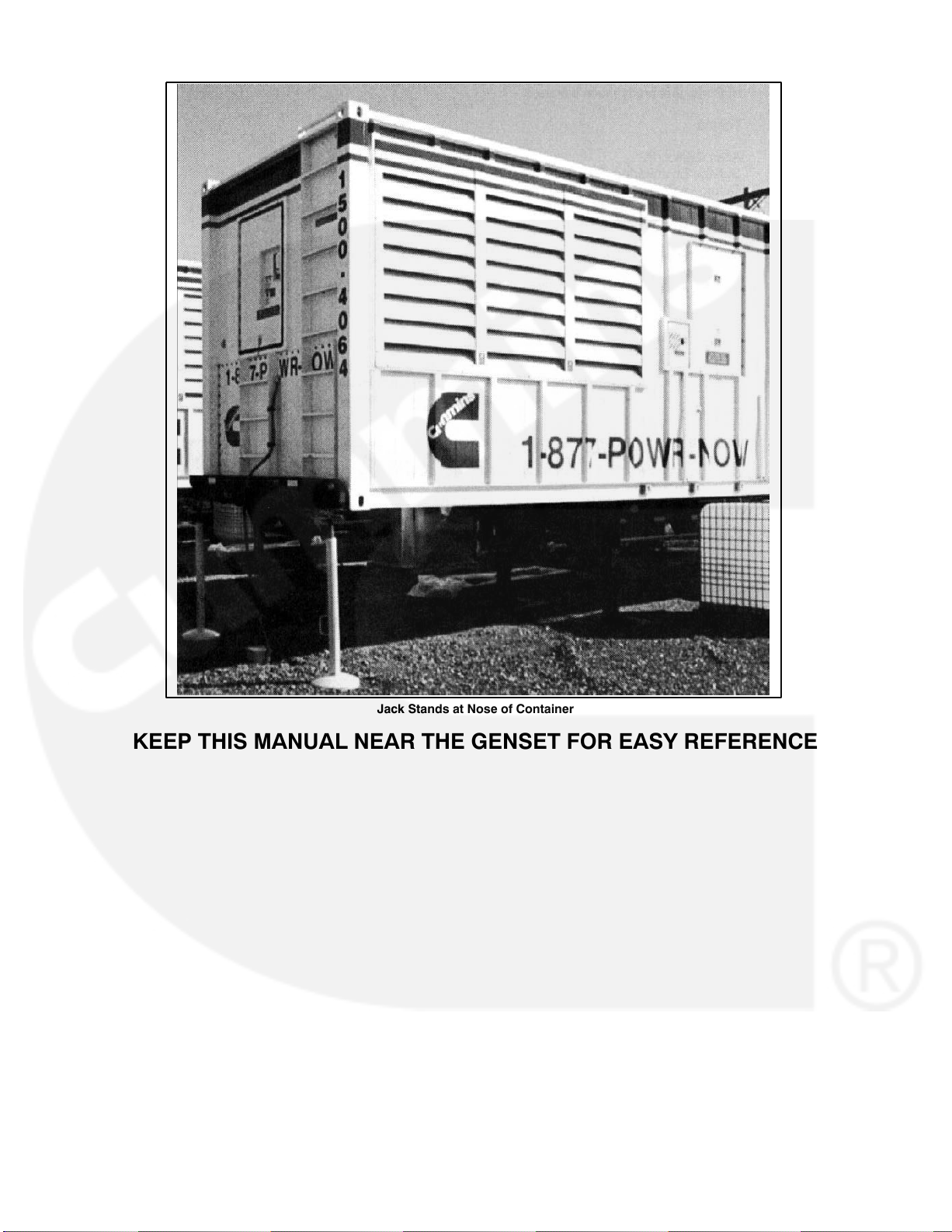
Jack Stands at Nose of Container
KEEP THIS MANUAL NEAR THE GENSET FOR EASY REFERENCE
vi
Page 9
1. Introduction
ABOUT THIS MANUAL
This manual provides installation instructions for the generator set models listed on the front cover. This manual includes the following information:
Mounting Recommendations - for fastening generator set to base and space requirements for normal operation
and service.
Mechanical and Electrical Connections - covers most aspects of the generator set installation.
Optional Enclosure Electrical Connections - covers installation of enclosure optional features.
Prestart − checklist of items or procedures needed to prepare generator set for operation.
Initial Startup − test complete system to ensure proper installation, satisfactory performance, and safe operation.
Refer to Operators Manual for troubleshooting information.
Installation Checklist − reference checks upon completion of installation.
This manual DOES NOT provide application information for selecting a generator set or designing the com-
plete installation. If it is necessary to design the various integrated systems (fuel, exhaust, cooling, etc.), addi-
tional information is required. Review standard installation practices. For engineering data specific to the gen-
erator set, refer to the Specification and Data Sheets. For application information, refer to Application Manual
T-030, “Liquid Cooled Generator Sets”.
INSTALLATION OVERVIEW
These installation recommendations apply to typical installations with standard model generator
sets. Whenever possible, these recommendations also cover factory designed options or modifications. How-
ever, because of the many variables in any installation, it is not possible to provide specific recommendations
for every situation. If there are any questions not answered by this manual, contact your nearest Cummins
Power Generation distributor for assistance.
Application and Installation
A power system must be carefully planned and correctly installed for proper operation. This involves two es-
sential elements: application and installation.
Application (as it applies to generator set installations) refers to the design of the complete power system that
usually includes power distribution equipment, transfer switches, ventilation equipment, mounting pads, and
cooling, exhaust, and fuel systems. Each component must be correctly designed so the complete system will
function as intended. Application and design is an engineering function generally done by specifying engi-
neers or other trained specialists. Specifying engineers or other trained specialists are responsible for the de-
sign of the complete power system and for selecting the materials and products required.
Installation refers to the actual set-up and assembly of the power system. The installers set up and connect
the various components of the system as specified in the system design plan. The complexity of the power
system normally requires the special skills of qualified electricians, plumbers, sheetmetal workers, etc. to
complete the various segments of the installation. This is necessary so all components are assembled using
standard methods and practices.
1-1
Page 10
Safety Considerations
The generator set has been carefully designed to provide safe and efficient service when properly installed,
maintained, and operated. However, the overall safety and reliability of the complete system is dependent on
many factors outside the control of the generator set manufacturer. To avoid possible safety hazards, make all
mechanical and electrical connections to the generator set exactly as specified in this manual. All systems
external to the generator (fuel, exhaust, electrical, etc.) must comply with all applicable codes. Make certain all
required inspections and tests have been completed and all code requirements have been satisfied before
certifying the installation is complete and ready for service.
Standby Heating Devices
In accordance with NFPA 110, Cummins Power Generation recommends installing diesel standby generator
sets (life safety systems) equipped with engine jacket water coolant heaters in locations where the minimum
ambient temperature is above 40
maintain the water jacket temperature determined by the manufacturer for cold start and load acceptance for
the type of system. Although most Cummins Power Generation generator sets will start in temperatures down
to −25
F (−32C) when equipped with engine jacket water coolant heaters, it might take more than 10 seconds
to warm the engine before a load can be applied when ambient temperatures are below 40
On generator sets equipped with a graphic display, the Low Coolant Temperature (Code 210) message, in
conjunction with illumination of the Warning LED, is provided to meet the requirements of NFPA 110. The en-
gine cold sensing logic initiates a warning when the engine jacket water coolant temperature falls below 70
C). In applications where the ambient temperature falls below 40F (4C), a cold engine may be indicated
(21
even though the coolant heaters are connected and operating correctly. Under these conditions, although the
generator set may start, it may not be able to accept load within 10 seconds. When this condition occurs, check
the coolant heaters for proper operation. If the coolant heaters are operating properly, other precautions may
be necessary to warm the engine before applying a load.
F (4C). NFPA also requires that the engine be heated as necessary to
F (4C).
F
Product Modifications
Agency certified products purchased from Cummins Power Generation comply only with those specific re-
quirements and as noted on company product specification sheets. Subsequent modifications must meet
commonly accepted engineering practices and/or local and national codes and standards. Product modifica-
tions must be submitted to the local authority having jurisdiction for approval.
1-2
Page 11
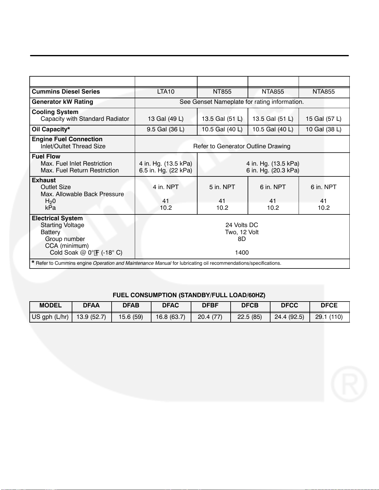
2. Specifications
MODEL DFAA/DFAB/DFAC DFBF DFCB/DFCC DFCE
Cummins Diesel Series LTA10 NT855 NTA855 NTA855
Generator kW Rating See Genset Nameplate for rating information.
Cooling System
Capacity with Standard Radiator
Oil Capacity* 9.5 Gal (36 L) 10.5 Gal (40 L) 10.5 Gal (40 L) 10 Gal (38 L)
Engine Fuel Connection
Inlet/Oultet Thread Size
Fuel Flow
Max. Fuel Inlet Restriction
Max. Fuel Return Restriction
Exhaust
Outlet Size
Max. Allowable Back Pressure
H
0
2
kPa
Electrical System
Starting Voltage
Battery
Group number
CCA (minimum)
Cold Soak @ 0F (-18 C)
* Refer to Cummins engine Operation and Maintenance Manual for lubricating oil recommendations/specifications.
13 Gal (49 L) 13.5 Gal (51 L) 13.5 Gal (51 L) 15 Gal (57 L)
Refer to Generator Outline Drawing
4 in. Hg. (13.5 kPa)
6.5 in. Hg. (22 kPa)
4 in. NPT
41
10.2
5 in. NPT
41
10.2
24 Volts DC
Two, 12 Volt
4 in. Hg. (13.5 kPa)
6 in. Hg. (20.3 kPa)
6 in. NPT
41
10.2
8D
1400
6 in. NPT
10.2
41
FUEL CONSUMPTION (STANDBY/FULL LOAD/60HZ)
MODEL
US gph (L/hr) 13.9 (52.7) 15.6 (59) 16.8 (63.7) 20.4 (77) 22.5 (85) 24.4 (92.5) 29.1 (110)
DFAA DFAB DFAC DFBF DFCB DFCC DFCE
2-1
Page 12

MODEL DFEB DFEC DFED
Cummins Diesel Series KTA19 KTA19 KTA19-G4
Generator kW Rating See Genset Nameplate for rating information.
Cooling System
Capacity with Standard Radiator
Oil Capacity* 12 Gal (45 L)
Engine Fuel Connection
Inlet/Oultet Thread Size
Fuel Flow
Max. Fuel Inlet Restriction
Max. Fuel Return Restriction
Exhaust
Outlet Size
Max. Allowable Back Pressure
H
0
2
kPa
Electrical System
Starting Voltage
Battery
Group number
CCA (minimum)
Cold Soak @ 0F (-18 C)
* Refer to Cummins engine Operation and Maintenance Manual for lubricating oil recommendations/specifications.
5 in. NPT
40.8
10.2
Refer to Generator Outline Drawing
24 Gal (91 L)
4 in. Hg. (13.5 kPa)
6.5 in. Hg. (22 kPa)
6 in. NPT
40.8
10.2
24 Volts DC
Two, 12 Volt
8D
1400
6 in. NPT
40.8
10.2
FUEL CONSUMPTION (STANDBY/FULL LOAD/60HZ)
MODEL
US gph (L/hr) 28.9 (109.5) 31 (117.5) 34 (128.9)
DFEB DFEC DFED
2-2
Page 13
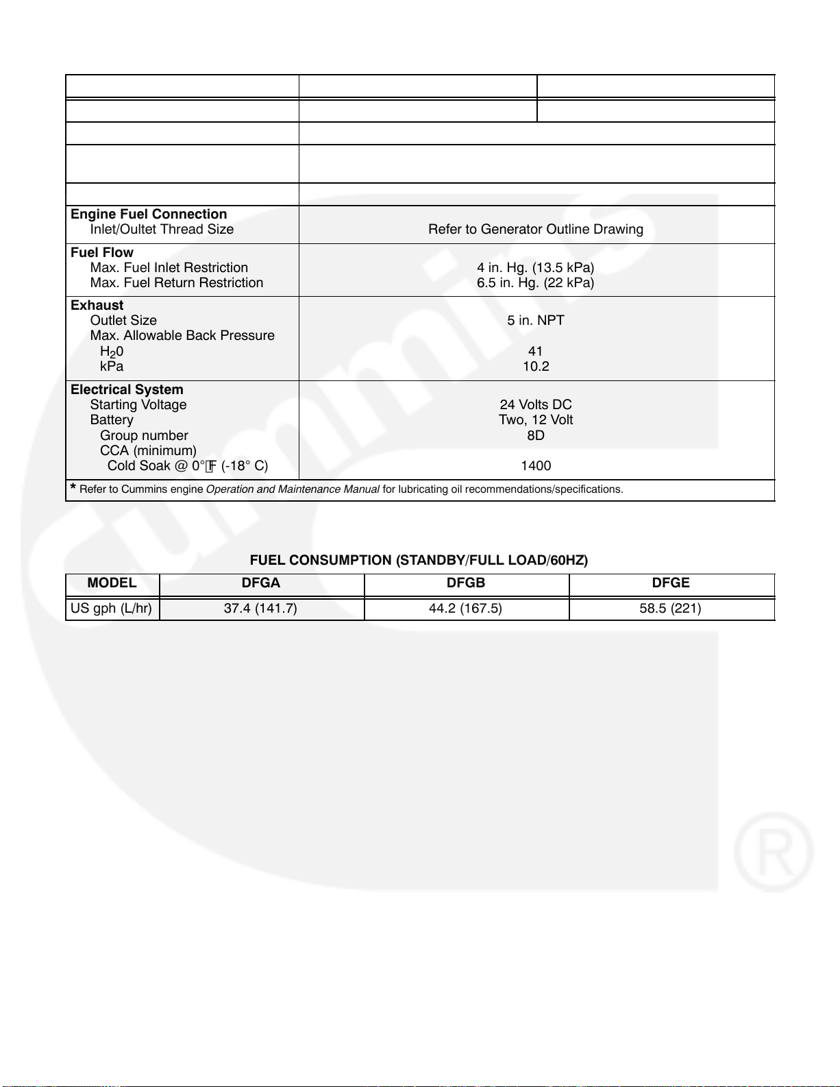
MODEL DFGA/DFGB DFGE
Cummins Diesel Series VTA28-G5 VTA28-G7
Generator kW Rating See Genset Nameplate for rating information.
Cooling System
Capacity with Standard Radiator
Oil Capacity* 22.25 Gal (84 L)
Engine Fuel Connection
Inlet/Oultet Thread Size
Fuel Flow
Max. Fuel Inlet Restriction
Max. Fuel Return Restriction
Exhaust
Outlet Size
Max. Allowable Back Pressure
H
0
2
kPa
Electrical System
Starting Voltage
Battery
Group number
CCA (minimum)
Cold Soak @ 0F (-18 C)
* Refer to Cummins engine Operation and Maintenance Manual for lubricating oil recommendations/specifications.
Refer to Generator Outline Drawing
44 Gal (167 L)
4 in. Hg. (13.5 kPa)
6.5 in. Hg. (22 kPa)
5 in. NPT
41
10.2
24 Volts DC
Two, 12 Volt
8D
1400
FUEL CONSUMPTION (STANDBY/FULL LOAD/60HZ)
MODEL
US gph (L/hr) 37.4 (141.7) 44.2 (167.5) 58.5 (221)
DFGA DFGB DFGE
2-3
Page 14
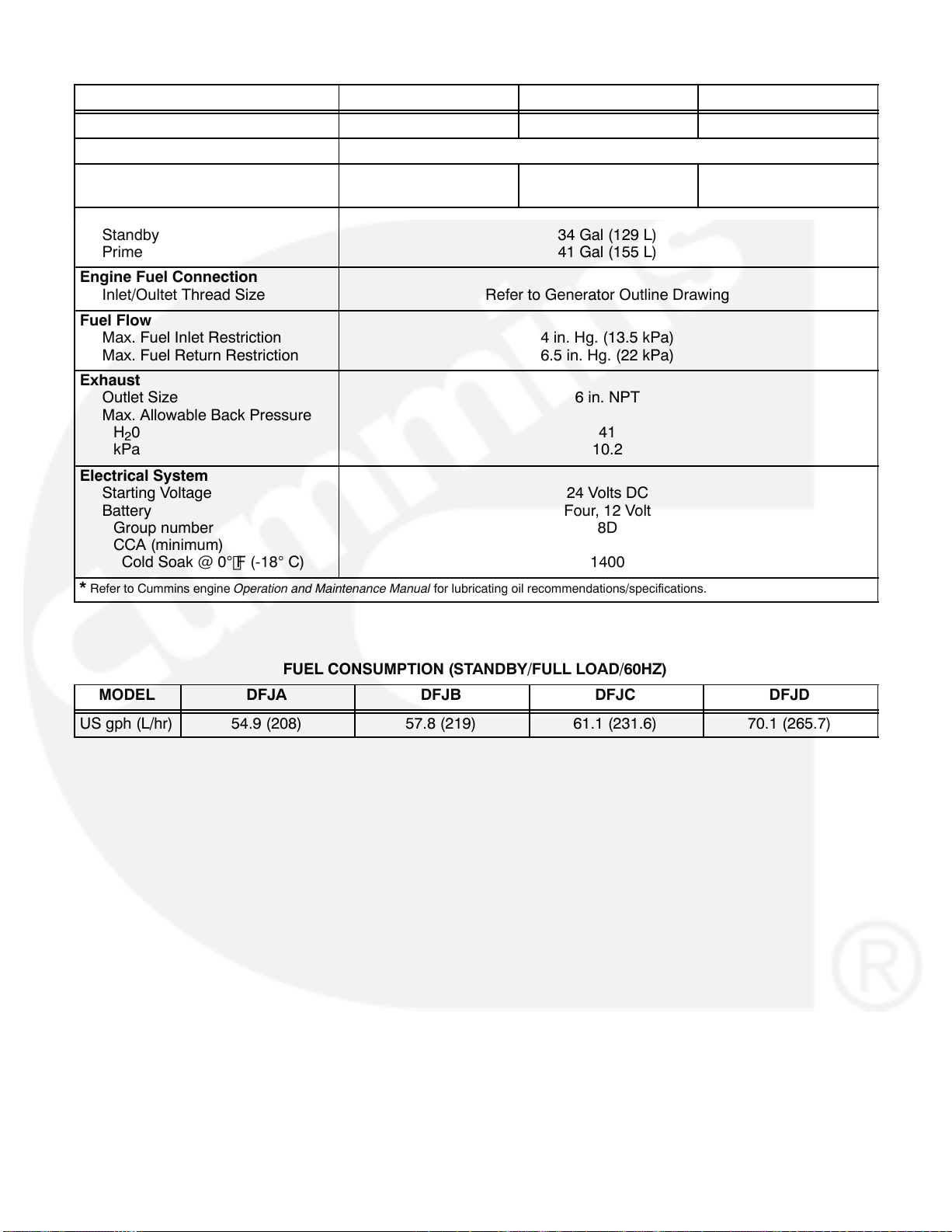
MODEL DFJA DFJB/DFJC DFJD
Cummins Diesel Series KTA38 KTA38 KTA38
Generator kW Rating See Genset Nameplate for rating information.
Cooling System
Capacity with Standard Radiator
Oil Capacity*
Standby
Prime
Engine Fuel Connection
Inlet/Oultet Thread Size
Fuel Flow
Max. Fuel Inlet Restriction
Max. Fuel Return Restriction
Exhaust
Outlet Size
Max. Allowable Back Pressure
H
0
2
kPa
Electrical System
Starting Voltage
Battery
Group number
CCA (minimum)
Cold Soak @ 0F (-18 C)
* Refer to Cummins engine Operation and Maintenance Manual for lubricating oil recommendations/specifications.
81.5 Gal (308 L) 85.3 Gal (323 L) 68.9 Gal (337 L)
34 Gal (129 L)
41 Gal (155 L)
Refer to Generator Outline Drawing
4 in. Hg. (13.5 kPa)
6.5 in. Hg. (22 kPa)
6 in. NPT
41
10.2
24 Volts DC
Four, 12 Volt
8D
1400
FUEL CONSUMPTION (STANDBY/FULL LOAD/60HZ)
MODEL
US gph (L/hr) 54.9 (208) 57.8 (219) 61.1 (231.6) 70.1 (265.7)
DFJA DFJB DFJC DFJD
2-4
Page 15
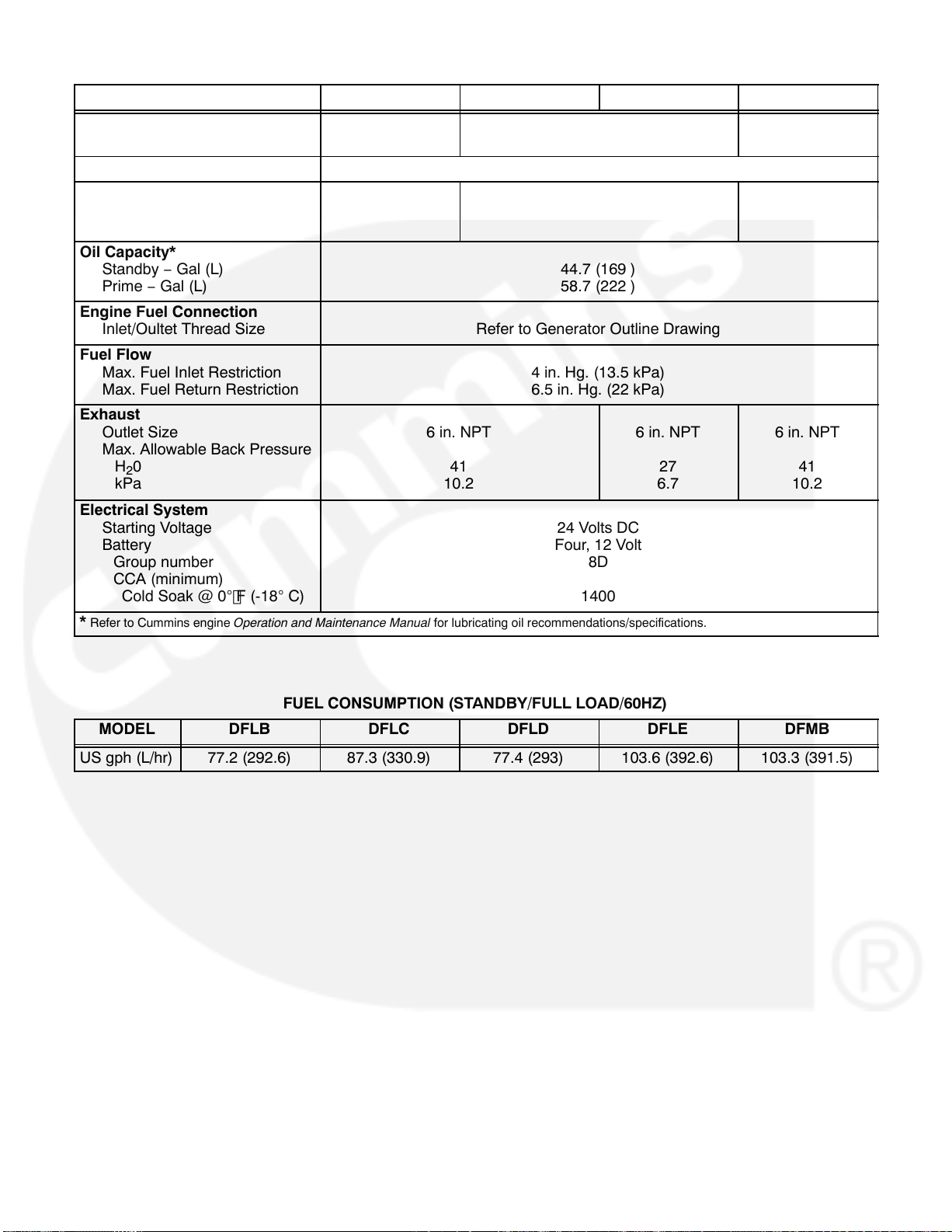
MODEL DFLB DFLC/DFLD DFLE DFMB
Cummins Diesel
Series
Generator kW Rating See Genset Nameplate for rating information.
Cooling System
Capacity w/Standard Ra-
diator − Gal (L)
Oil Capacity*
Standby − Gal (L)
Prime − Gal (L)
Engine Fuel Connection
Inlet/Oultet Thread Size
Fuel Flow
Max. Fuel Inlet Restriction
Max. Fuel Return Restriction
Exhaust
Outlet Size
Max. Allowable Back Pressure
H
0
2
kPa
Electrical System
Starting Voltage
Battery
Group number
CCA (minimum)
Cold Soak @ 0F (-18 C)
* Refer to Cummins engine Operation and Maintenance Manual for lubricating oil recommendations/specifications.
KTA50 KTA50 KTTA50
92 (348) 102 (386) 102 (386)
44.7 (169 )
58.7 (222 )
Refer to Generator Outline Drawing
4 in. Hg. (13.5 kPa)
6.5 in. Hg. (22 kPa)
6 in. NPT
41
10.2
24 Volts DC
Four, 12 Volt
8D
1400
6 in. NPT
27
6.7
6 in. NPT
41
10.2
FUEL CONSUMPTION (STANDBY/FULL LOAD/60HZ)
MODEL
US gph (L/hr) 77.2 (292.6) 87.3 (330.9) 77.4 (293) 103.6 (392.6) 103.3 (391.5)
DFLB DFLC DFLD DFLE DFMB
2-5
Page 16
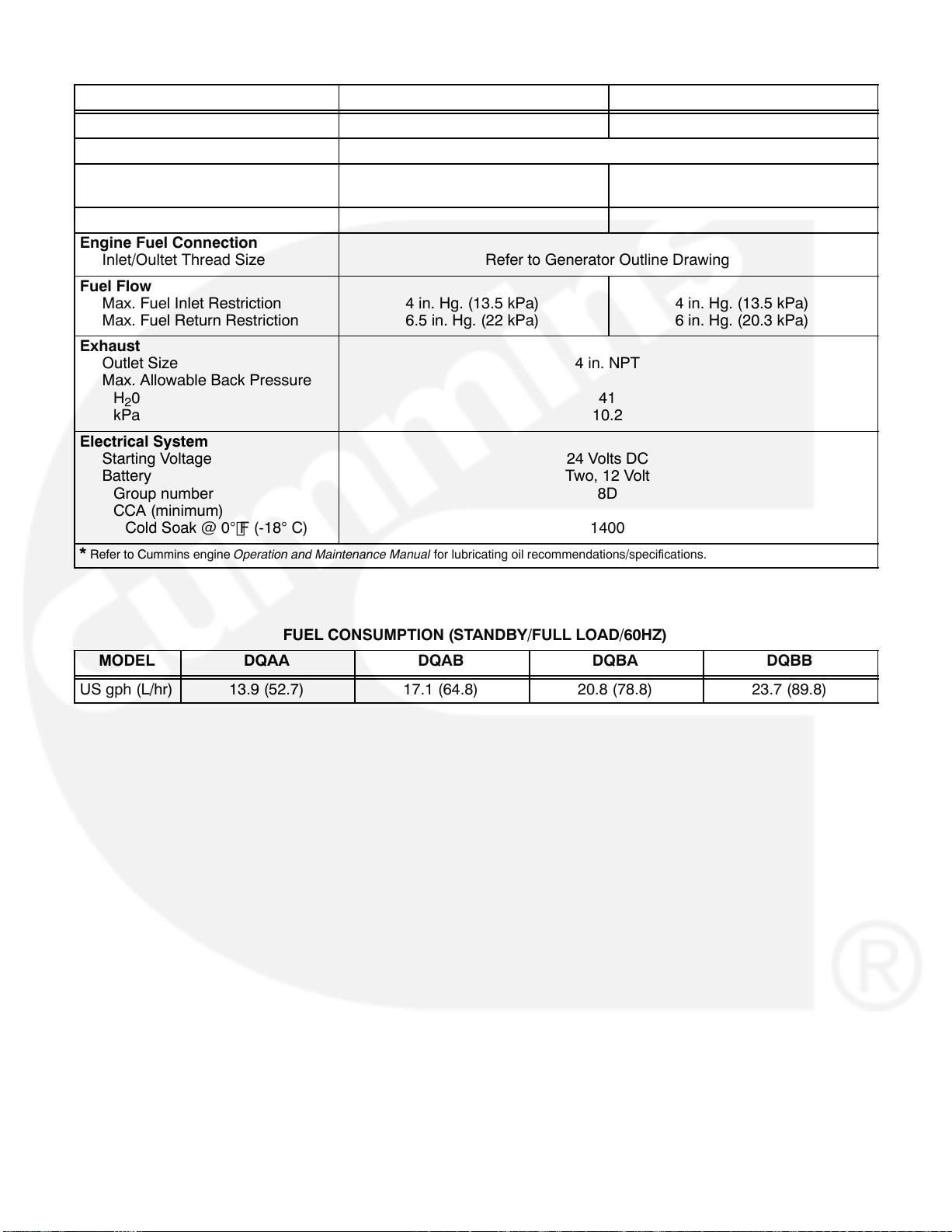
MODEL DQAA/DQAB DQBA/DQBB
Cummins Diesel Series M11 N14
Generator kW Rating See Genset Nameplate for rating information.
Cooling System
Capacity with Standard Radiator
Oil Capacity* 9.5 Gal (36 L) 10 Gal (38 L)
Engine Fuel Connection
Inlet/Oultet Thread Size
Fuel Flow
Max. Fuel Inlet Restriction
Max. Fuel Return Restriction
Exhaust
Outlet Size
Max. Allowable Back Pressure
H
0
2
kPa
Electrical System
Starting Voltage
Battery
Group number
CCA (minimum)
Cold Soak @ 0F (-18 C)
* Refer to Cummins engine Operation and Maintenance Manual for lubricating oil recommendations/specifications.
13 Gal (49 L) 13.5 Gal (51 L)
Refer to Generator Outline Drawing
4 in. Hg. (13.5 kPa)
6.5 in. Hg. (22 kPa)
4 in. NPT
41
10.2
24 Volts DC
Two, 12 Volt
8D
1400
4 in. Hg. (13.5 kPa)
6 in. Hg. (20.3 kPa)
FUEL CONSUMPTION (STANDBY/FULL LOAD/60HZ)
MODEL
US gph (L/hr) 13.9 (52.7) 17.1 (64.8) 20.8 (78.8) 23.7 (89.8)
DQAA DQAB DQBA DQBB
2-6
Page 17
3. Mounting the Generator Set
GENERAL
Generator set installations must be engineered so the generator set will function properly under the expected
load conditions. Use these instructions as a general guide only. Follow the instructions of the consulting engi-
neer when locating or installing any components. The complete installation must comply with all local and
state building codes, fire ordinances, and other applicable regulations.
Requirements to be considered prior to installation:
Level mounting surface
Adequate cooling air
Adequate fresh induction air
Discharge of generator set air
Non-combustible mounting surface.
Discharge of exhaust gases
Electrical connections
Accessibility for operation and servicing
Noise levels
Vibration isolation
CAUTION
drive must be checked after the genset is mounted. Failure to check fan drive alignment can result in
severe fan/radiator damage. Refer to Section 11 for alignment procedure.
Model DFLE 50C radiator-cooled genset only: The alignment of the cooling system fan
LOCATION
Generator set location is decided mainly by related systems such as ventilation, wiring, fuel, and exhaust. The
set should be located as near as possible to the main power service entrance. Exhaust must not be able to
enter or accumulate around inhabited areas.
Provide a location away from extreme ambient temperatures and protect the generator set from adverse
weather conditions. An optional housing is available for outside operation.
WARNING
INCORRECT INSTALLATION, SERVICE OR PARTS REPLACEMENT CAN RESULT IN SEVERE
PERSONAL INJURY, DEATH, AND/OR EQUIPMENT DAMAGE. SERVICE PERSONNEL MUST
BE TRAINED AND EXPERIENCED TO PERFORM ELECTRICAL AND MECHANICAL COMPONENT INSTALLATION.
3-1
Page 18

IMPORTANT
DEPENDING ON YOUR LOCATION AND INTENDED USE, FEDERAL, STATE OR LOCAL LAWS
AND REGULATIONS MAY REQUIRE YOU TO OBTAIN AN AIR QUALITY EMISSIONS PERMIT
BEFORE BEGINNING INSTALLATION OF YOUR GENSET. BE SURE TO CONSULT LOCAL
POLLUTION CONTROL OR AIR QUALITY AUTHORITIES BEFORE COMPLETING YOUR
CONSTRUCTION PLANS.
MOUNTING
Generator sets are mounted on a steel skid that provides proper support. The engine-generator assembly is
isolated from the skid frame by rubber mounts that provide adequate vibration isolation for normal installa-
tions. Where required by building codes or special isolation needs, generator sets may be mounted on rubber
pads or mechanical spring isolators. The use of unapproved isolators may result in harmful resonances and
may void the genset warranty.
Mount the generator set on a substantial and level base such as a concrete pad. A non-combustible material
must be used for the pad.
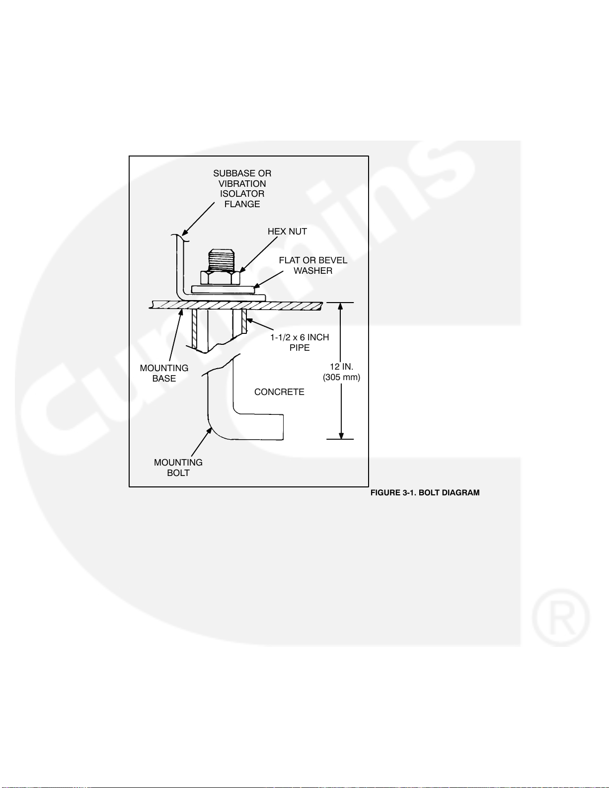
Use 5/8 inch or 16 mm anchored mounting bolts to secure the vibration isolators to the base. Secure the vibra-
tion isolators to the skid using flat or bevel washer and hexagonal nut for each bolt (see Figure 3-1). The 1-1/2 x
6 inch pipe inserted over the mounting bolts allows minor adjustment of the bolts to align them to the holes in
the subbase or vibration isolator.
Locate the isolators as shown on the generator set Outline Drawing referenced in the Data Sheet.
3-2
Page 19
ACCESS TO SET
Generally, at least 1 meter (3 feet) of clearance should be provided on all sides of the generator set for maintenance and service access. (Increase clearance by width of door if optional housing is used.) A raised foundation or slab of 150 mm (6 inches) or more above floor level will make servicing easier.
Lighting should be adequate for operation, maintenance and service operations and should be connected on
the load side of the transfer switch so that it is available at all times.
SUBBASE OR
VIBRATION
ISOLATOR
FLANGE
HEX NUT
FLAT OR BEVEL
WASHER
1-1/2 x 6 INCH
PIPE
MOUNTING
BASE
MOUNTING
BOLT
12 IN.
(305 mm)
CONCRETE
FIGURE 3-1. BOLT DIAGRAM
3-3
Page 20
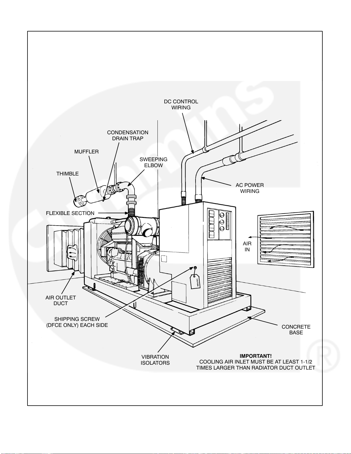
MUFFLER
THIMBLE
FLEXIBLE SECTION
DC CONTROL
WIRING
CONDENSATION
DRAIN TRAP
SWEEPING
ELBOW
AC POWER
WIRING
AIR
IN
AIR OUTLET
DUCT
SHIPPING SCREW
(DFCE ONLY) EACH SIDE
VIBRATION
ISOLATORS
FIGURE 3-2. TYPICAL INSTALLATION
COOLING AIR INLET MUST BE AT LEAST 1-1/2
TIMES LARGER THAN RADIATOR DUCT OUTLET
AREA ON RADIATOR COOLED MODELS
FLOW OR COOLING AIR AND HEATED AIR CAN
BE CONTROLLED BY AUTOMATICALLY
3-4
CONCRETE
BASE
IMPORTANT!
OPERATED LOUVRES
Page 21
VIBRATION ISOLATORS
Installation and Adjustment Procedure
1. Place the vibration isolators (Figure 3-3) on the genset support structure. The isolators should be
shimmed or grouted to ensure that all of the isolator bases are within 0.25 inch (6 mm) elevation of each
other. The surface that the isolator bases rest on must also be flat and level.
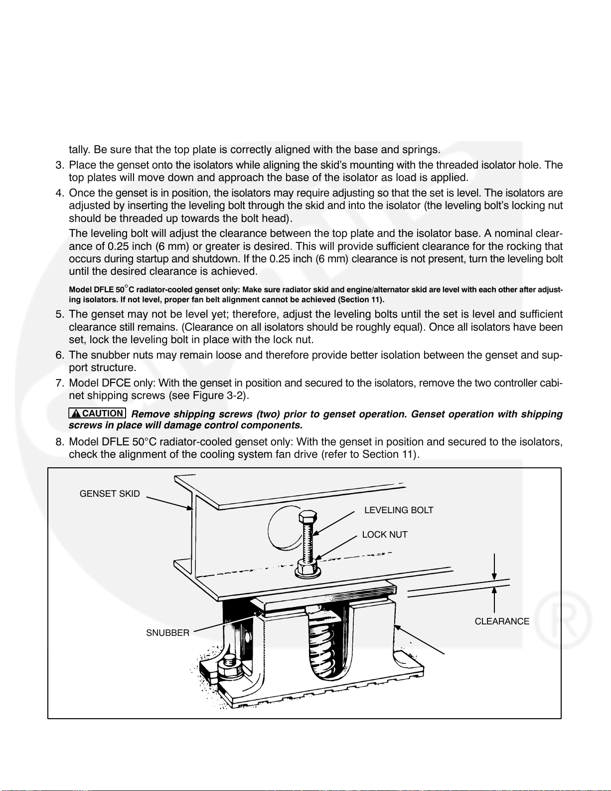
2. Loosen the side snubber lock nuts so that the top plate of the isolator is free to move vertically and horizontally. Be sure that the top plate is correctly aligned with the base and springs.
3. Place the genset onto the isolators while aligning the skid’s mounting with the threaded isolator hole. The
top plates will move down and approach the base of the isolator as load is applied.
4. Once the genset is in position, the isolators may require adjusting so that the set is level. The isolators are
adjusted by inserting the leveling bolt through the skid and into the isolator (the leveling bolt’s locking nut
should be threaded up towards the bolt head).
The leveling bolt will adjust the clearance between the top plate and the isolator base. A nominal clear-
ance of 0.25 inch (6 mm) or greater is desired. This will provide sufficient clearance for the rocking that
occurs during startup and shutdown. If the 0.25 inch (6 mm) clearance is not present, turn the leveling bolt
until the desired clearance is achieved.
Model DFLE 50C radiator-cooled genset only: Make sure radiator skid and engine/alternator skid are level with each other after adjust-
ing isolators. If not level, proper fan belt alignment cannot be achieved (Section 11).
5. The genset may not be level yet; therefore, adjust the leveling bolts until the set is level and sufficient
clearance still remains. (Clearance on all isolators should be roughly equal). Once all isolators have been
set, lock the leveling bolt in place with the lock nut.
6. The snubber nuts may remain loose and therefore provide better isolation between the genset and sup-
port structure.
7. Model DFCE only: With the genset in position and secured to the isolators, remove the two controller cabi-
net shipping screws (see Figure 3-2).
CAUTION
screws in place will damage control components.
Remove shipping screws (two) prior to genset operation. Genset operation with shipping
8. Model DFLE 50C radiator-cooled genset only: With the genset in position and secured to the isolators,
check the alignment of the cooling system fan drive (refer to Section 11).
GENSET SKID
LEVELING BOLT
LOCK NUT
CLEARANCE
SNUBBER
BASE
FIGURE 3-3. VIBRATION ISOLATORS
3-5
Page 22
ALIGNING GENERATOR WITH ENGINE (750 KW GENSETS AND LARGER)
Proper alignment of the generator and engine assemblies is necessary to avoid premature wear and improper
operation of the genset. Review the following alignment conditions and procedures for aligning the generator
assembly to engine flywheel housing.
Angular Misalignment
Angular misalignment is the result of the generator bearing center axis not aligning with axis of the engine
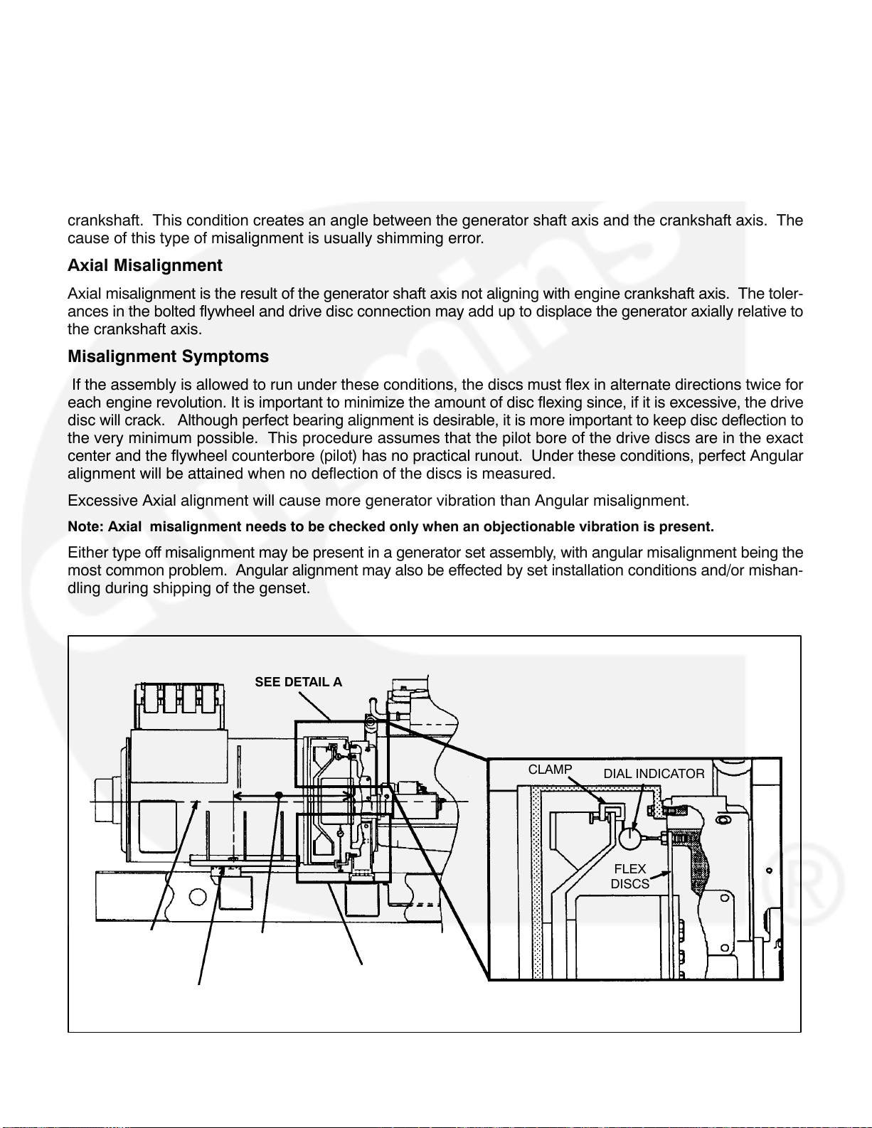
crankshaft. This condition creates an angle between the generator shaft axis and the crankshaft axis. The
cause of this type of misalignment is usually shimming error.
Axial Misalignment
Axial misalignment is the result of the generator shaft axis not aligning with engine crankshaft axis. The toler-
ances in the bolted flywheel and drive disc connection may add up to displace the generator axially relative to
the crankshaft axis.
Misalignment Symptoms
If the assembly is allowed to run under these conditions, the discs must flex in alternate directions twice for
each engine revolution. It is important to minimize the amount of disc flexing since, if it is excessive, the drive
disc will crack. Although perfect bearing alignment is desirable, it is more important to keep disc deflection to
the very minimum possible. This procedure assumes that the pilot bore of the drive discs are in the exact
center and the flywheel counterbore (pilot) has no practical runout. Under these conditions, perfect Angular
alignment will be attained when no deflection of the discs is measured.
Excessive Axial alignment will cause more generator vibration than Angular misalignment.
Note: Axial misalignment needs to be checked only when an objectionable vibration is present.
Either type off misalignment may be present in a generator set assembly, with angular misalignment being the
most common problem. Angular alignment may also be effected by set installation conditions and/or mishan-
dling during shipping of the genset.
SEE DETAIL A
CLAMP
DIAL INDICATOR
FLEX
DISCS
GENERATOR
AND ENGINE
CRANKSHAFT
CENTERLINE
SHIMS
MOUNTING BOLT
TO DISC
MEASUREMENT
FIGURE 3-4. ANGULAR ALIGNMENT MEASUREMENT
AXIAL
ALIGNMENT
3-6
DETAIL A
Page 23
Angular Alignment Procedure
WARNING
Accidental starting of the generator set during this procedure presents the hazard of severe personal injury or death. Make sure to disconnect the negative (-) battery cable(s) before beginning.
Fasten a dial indicator to either the generator shaft or the cooling fan with the sensing point resting on the
capscrew head or the flat surface of the drive disc at the bolt circle diameter, see Figure 3-4. Bar the engine
over in a clockwise rotation as viewed from engine flywheel. Do not allow it to roll back on compression at the
end of the travel of each reading. It is unnecessary to zero the indicator since the total indicator reading (T.I.R.)
of the deflection measurement to the bolt heads is what is required. T.I.R. will be the sum of the maximum
positive and negative dial indicator readings as the engine completes one revolution.
CAUTION
Do not bar engine over by prying on fan blade. This may damage the blade and result in
premature, sudden blade failure.
Sample Generator Runout Readings: When taking the deflection readings described, make a diagram similar
to the example shown in Figure 3-5, with a total indicator reading of .025”. (The highest positive value of +.010”
and the largest negative value of -.015”.) The indicator is closer to the top and further away at the bottom. This
example indicates that the generator bearing is high. Since the side readings are equal, the generator is cen-
tered side to side. To lower the generator, remove equal shims from under both generator mounting feet. To
approximate the amount of shims to remove or add:
1. Measure the distance between the center of the generator shaft to the point the indicator is measuring at.
(For example; a SAE 18 Disc coupling distance is 10.7”).
2. Measure the distance from the generator side of the flex discs to the center of the generator mounting
bolt, refer to Figure 3-4. (For example; a HC6 Frame’s distance is 28.4”.)
3. Compare the distance measured in steps 1 and 2. (28.4” vs 10.7” or a 2.65 to 1 ratio.) Multiply this ratio
times one half the T.I.R. (In our example, .025” divided by 2 is .0125”. This, times 2.65 equals .033”.
Therefore, remove .033” of shims from under both mounting feet.)
3-7
Page 24
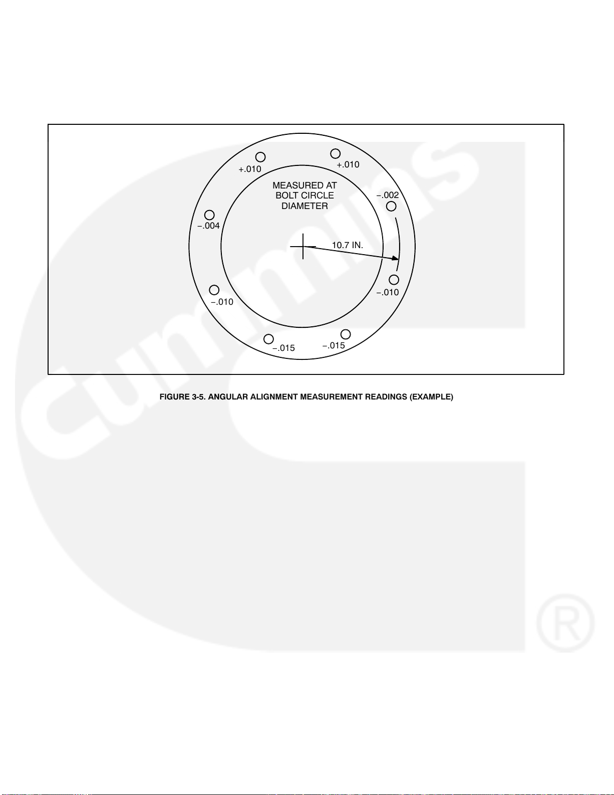
In general, the T.I.R. should not be more than .001” for each inch of radius (center of shaft to indicator axis). If
we use our example of 10.7 inches, then the maximum T.I.R. would be .011”. This would only require a correction of .014” from the T.I.R. of .025”. (A reading of +.002 at the top and −.009 at the bottom would fall within the
satisfactoryrange.)
+.010
MEASURED AT
BOLT CIRCLE
DIAMETER
−.004
−.010
−.015
FIGURE 3-5. ANGULAR ALIGNMENT MEASUREMENT READINGS (EXAMPLE)
+.010
−.002
10.7 IN.
−.010
−.015
3-8
Page 25
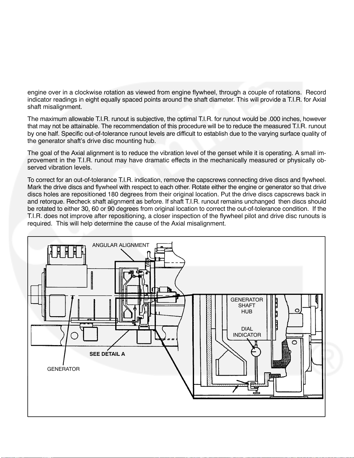
Axial Alignment Procedure
Note: Axial misalignment needs to be checked only when an objectionable vibration is present.
If excessive vibration remains after the angular alignment, check for concentric alignment of the generator
shaft/engine crankshaft axis.
Fasten dial indicator holding device to skid base, engine block, or generator shell with a magnetic base or
clamp and position so the sensor point of indicator rests on the generator shaft hub, see Figure 3-6. Bar the
engine over in a clockwise rotation as viewed from engine flywheel, through a couple of rotations. Record
indicator readings in eight equally spaced points around the shaft diameter. This will provide a T.I.R. for Axial
shaft misalignment.
The maximum allowable T.I.R. runout is subjective, the optimal T.I.R. for runout would be .000 inches, however
that may not be attainable. The recommendation of this procedure will be to reduce the measured T.I.R. runout
by one half. Specific out-of-tolerance runout levels are difficult to establish due to the varying surface quality of
the generator shaft’s drive disc mounting hub.
The goal of the Axial alignment is to reduce the vibration level of the genset while it is operating. A small im-
provement in the T.I.R. runout may have dramatic effects in the mechanically measured or physically ob-
served vibration levels.
To correct for an out-of-tolerance T.I.R. indication, remove the capscrews connecting drive discs and flywheel.
Mark the drive discs and flywheel with respect to each other. Rotate either the engine or generator so that drive
discs holes are repositioned 180 degrees from their original location. Put the drive discs capscrews back in
and retorque. Recheck shaft alignment as before. If shaft T.I.R. runout remains unchanged then discs should
be rotated to either 30, 60 or 90 degrees from original location to correct the out-of-tolerance condition. If the
T.I.R. does not improve after repositioning, a closer inspection of the flywheel pilot and drive disc runouts is
required. This will help determine the cause of the Axial misalignment.
GENERATOR
AND ENGINE
CRANKSHAFT
CENTERLINE
ANGULAR ALIGNMENT
GENERATOR
SHAFT
HUB
DIAL
INDICATOR
SEE DETAIL A
CLAMP
FAN HOUSING
DETAIL A
FIGURE 3-6. AXIAL ALIGNMENT MEASUREMENT
3-9
Page 26

THIS PAGE LEFT INTENTIONALLY BLANK
3-10
Page 27

4. Mechanical Connections
GENERAL
The generator set mechanical system installation includes connecting the fuel, exhaust, ventilation and cooling systems. Before starting any type of fuel installation, all pertinent state and local codes must be complied
with and the installation must be inspected before the unit is put in service.
FUEL SYSTEM
Cummins engines normally use ASTM No. 2 diesel fuel. They will, however, operate on alternate diesel fuels
within the specifications shown in the Cummins engine Operation and Maintenance Manual.
In all fuel system installations, cleanliness is of the upmost importance. Make every effort to prevent entrance
of moisture, dirt or contaminants of any kind into the fuel system. Clean all fuel system components before
installing.
Note: A fuel filter/strainer/water separator of 100-120 mesh or equivalent (approximately 150 microns nominal)
must be fitted between either the main tank and day tank or between the main tank and the engine.
Use only compatible metal fuel lines to avoid electrolysis when fuel lines must be buried. Buried fuel lines must
be protected from corrosion.
CAUTION
and lines combines with the sulfur in diesel fuel to produce sulfuric acid. The molecular structure of
the copper or galvanized lines or tanks reacts with the acid and contaminates the fuel.
An electric solenoid valve in the supply line is recommended for all installations and required for indoor auto-
matic or remote starting installations. Connect the solenoid wires to the genset “Switched B+” circuit to open
the valve during generator set operation.
Separate fuel return lines to the day tank or supply tank must be provided for each generator set in a multiple-
set installation to prevent the return lines of idle sets from being pressurized. Fuel return lines must not contain
a shutoff device. Engine damage will occur if the engine is run with the return fuel lines blocked or restricted.
CAUTION
fuel restriction limit, engine damage will occur.
Fuel Return Restriction (or Pressure) Limit: Fuel return drain restriction (consisting of friction head and
static head) between the engine injector return line connection and the fuel tank must not exceed the limit
stated in the model-specific genset Data Sheet.
Never use galvanized or copper fuel lines, fittings or fuel tanks. Condensation in the tank
Never install shutoff device in fuel return line(s). If fuel return line(s) is blocked or exceeds
Fuel Lines − Routing
A flexible fuel hose(s) or section of flexible fuel hose(s) must be used between the engine’s fuel system and
fuel supply and return line(s) to protect the fuel system from damage caused by vibration, expansion and con-
traction. Flexible lines for connecting between the engine and the stationary fuel lines are supplied as standard
equipment.
WARNING
death. Always use flexible tubing between engine and fuel supply and return to avoid line failure and
leaks due to vibration. The fuel system must meet applicable codes.
Installation of the fuel hose must be done according to all applicable codes and standards, and installation
recommendations provided by the manufacturer. The supplied flexible hose is approved by the hose manufacture for use with the genset fuel type and product application.
Fuel leaks create fire and explosion hazards which can result in severe personal injury or
4-1
Page 28
Support fuel lines to restrain movement and prevent chaffing or contact with sharp edges, electrical wiring and
hot exhaust parts.
WARNING
Sparks and hot surfaces can ignite fuel, leading to severe personal injury or death. Do not
route fuel lines near electrical wiring or hot exhaust parts.
Fuel lines must be routed and secured to maintain a 1/2 inch (12.7 mm) minimum clearance from electrical
wiring and a 2 inch (51 mm) minimum clearance from hot exhaust parts.
ENGINE
FUEL
PUMP
DAY TANK
FUEL TRANSFER
PUMP ELECTRIC
MOTOR DRIVEN
VENTED
FILL CAP
SHUTOFF
VALVE
1 INCH
BAFFLE
FLOAT
SWITCH
INJECTOR FUEL
RETURN LINE
CONNECT TO
AC OUTPUT
SUPPLY
LINE
All models require a fuel return
line from injectors to tank.
VENT LINE
FILL PIPE
120 MESH FUEL
STRAINER
LARGER OVER-
FLOW LINE
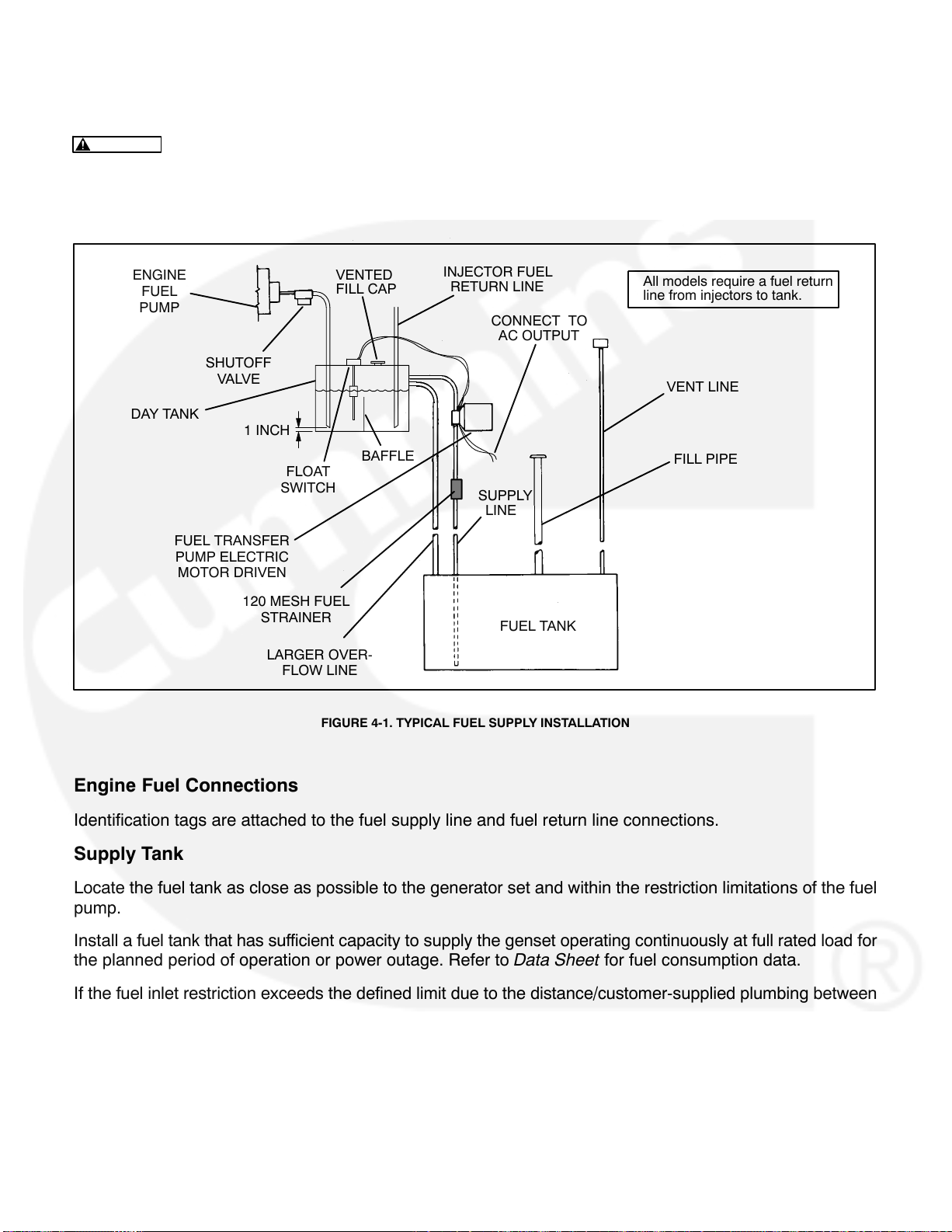
FIGURE 4-1. TYPICAL FUEL SUPPLY INSTALLATION
FUEL TANK
Engine Fuel Connections
Identification tags are attached to the fuel supply line and fuel return line connections.
Supply Tank
Locate the fuel tank as close as possible to the generator set and within the restriction limitations of the fuel
pump.
Install a fuel tank that has sufficient capacity to supply the genset operating continuously at full rated load for
the planned period of operation or power outage. Refer to Data Sheet for fuel consumption data.
If the fuel inlet restriction exceeds the defined limit due to the distance/customer-supplied plumbing between
the genset and the main fuel tank, a transfer tank (referred to as a day tank) and auxiliary pump will also be
required. If an overhead main fuel tank is installed, a transfer tank and float valve will be required to prevent fuel
head pressures from being placed on the fuel system components.
Note: For critical start applications, where generator sets are paralleled or must satisfy emergency start-time
requirements, it is recommended that a fuel tank or reservoir be located such that the lowest possible fuel level
is not less than 6 inches (150 mm) above the fuel pump inlet. This will prevent air from accumulating in the fuel
line while the set is in standby, eliminating the period during startup when it has to be purged.
4-2
Page 29
Fuel Inlet Pressure/Restriction Limit:: Engine performance and fuel system durability will be compromised
if the fuel inlet pressure or restriction limits are not adhered to. Fuel inlet pressure or restriction must not exceed the limits stated in the model-specific genset Data Sheet.
Day Tank (If Used)
Fuel day tanks are used when fuel inlet restriction limits can not be met, or the supply tank is overhead and
presents problems of high fuel head pressure for the fuel inlet and return lines.
Supply Tank Lower Than Engine: With this installation, the day tank is installed near the generator set, be-
low the fuel injection system and within the fuel inlet restriction limit. Install an auxiliary fuel pump, to pump fuel
from the supply tank to the day tank. A float switch in the day tank controls operation of the auxiliary fuel pump.
Note: The supply tank top must be below the day tank top to prevent siphoning from the fuel supply to the day
tank.
Provide a return line from the engine injection system return connection to the day tank. Plumb the return line
to the bottom of day tank as shown in Figure 4-1. Provide a day tank overflow line to the supply tank in case the
float switch fails to shut off the fuel transfer pump.
WARNING
Spilled fuel presents the hazard of fire or explosion which can result in severe personal
injury or death. Provide an overflow line to the supply tank from the day tank.
Supply Tank Higher Than Engine: Install the day tank near the generator set, but below the fuel injection
system. Use fuel line at least as large as the fuel pump inlet. The engine fuel return line must enter the day tank.
Include a shutoff valve in the fuel line between the fuel supply tank and the day tank to stop fuel flow when the
generator set is off.
WARNING
Spilled fuel can create environmental hazards. Check local requirements for containment
and prevention of draining to sewer and ground water.
EXHAUST SYSTEM
Pipe exhaust gases to the outside of any enclosure. Locate the exhaust outlets away from any air inlets to
avoid gases re-entering the enclosure. Exhaust installations are subject to various detrimental conditions
such as extreme heat, infrequent operation and light loads. Regularly inspect the exhaust system both visually
and audibly to see that the entire system remains fume tight and safe for operation.
WARNING
care during installation to provide a tight exhaust system. Terminate exhaust pipe away from en-
closed or sheltered areas, windows, doors and vents.
For indoor installation, the exhaust system must use sealed joint type fittings, (for example NPT fittings) to
provide a tighter exhaust system. Use of slip type fittings (secured with a muffler clamp) may allow leakage of
exhaust gases into the building.
Inhalation of exhaust gases can result in severe personal injury or death. Use extreme
WARNING
Inhalation of exhaust gases can result in severe personal injury or death. Use extreme
care during installation to provide a tight exhaust system. Use NPT or equivalent type fittings for all
indoor installations.
Use an approved thimble (Figure 4-2) where exhaust pipes pass through wall or partitions. Insulated wall/roof
thimbles are used where exhaust pipes pass through a combustible roof or wall. This includes structures, such
as wood framing or insulated steel decking, etc. Uninsulated wall/roof thimbles are used where exhaust pipes
pass through a non-combustible wall or roof, such as concrete. Refer to NFPA 37, Section 6-3. “Stationary
Combustion Engines and Gas Turbines” for accepted design practices. Build according to the code requirements in effect at the installation site.
4-3
Page 30
WARNING
Hot exhaust pipes can start a fire and cause severe injury or death if improperly routed
through walls. Use an approved thimble where exhaust pipes pass through walls or partitions.
WARNING
Inhalation of exhaust gases can result in severe personal injury or death. Do not use exhaust heat to warm a room, compartment or storage area.
Rain caps are available for the discharge end of vertical exhaust pipes. The rain cap clamps onto the end of the
pipe and opens due to exhaust discharge force from the generator set. When the generator set is stopped, the
rain cap automatically closes, protecting the exhaust system from rain, snow, etc.
Use a section of flexible exhaust pipe between the engine and remainder of exhaust system. Support exhaust
system to prevent weight from being applied to engine exhaust outlet elbow/turbocharger connection.
CAUTION
Weight applied to the engine manifold can result in turbocharger damage. Support the
muffler and exhaust piping so no weight or stress is applied to engine exhaust elbow.
The exhaust system design should meet local code requirements.
Note: Liability for injury, death, damage, and warranty expense due to use of unapproved mufflers or modifica-
tions becomes the responsibility of the person installing the unapproved muffler or performing the modifica-
tion. Contact a Cummins Power Generation distributor for approved exhaust system parts.
Avoid sharp bends by using sweeping, long radius elbows and provide adequate support for muffler and tail-
pipe. Pitch a horizontal run of exhaust pipe DOWNWARD (away from engine) to allow any moisture condensa-
tion to drain away from the engine. If an exhaust pipe must be turned upward, install a condensation trap at the
point where the rise begins (Figure 4-3).
Shield or insulate exhaust lines if there is danger of personal contact. Allow at least 12 inches (305 mm) of
clearance if the pipes pass close to a combustible wall or partition. Before installing insulation on exhaust sys-
tem components, check the exhaust system for leaks while operating the genset under full load and correct all
leaks.
WARNING
Exhaust pipes are very hot and they can cause severe personal injury or death from direct
contact or from fire hazard. Shield or insulate exhaust pipes if there is danger of personal contact or
when routed through walls or near other combustible materials.
4-4
Page 31

RAIN CAP
9 INCH
(230 mm)
HORIZONTAL
WALL OR PARTITION
VERTICAL
DRIP CAP
HOLES IN
END OF INNER
SLEEVE
ROOF
9 INCH
(230 mm)
AVOID
SHARP
BENDS
FIGURE 4-2. MOUNTING EXHAUST THIMBLE
IF EXHAUST LINE MUST BE
PITCHED UPWARD, CONSTRUCT
A TRAP AT POINT OF RISE
DRAIN CONDENSATION
TRAP PERIODICALLY
FIGURE 4-3. CONDENSATION TRAP
4-5
Page 32

VENTILATION AND COOLING
Generator sets dissipate heat and fumes that must be removed by proper cooling and ventilation.
Generator sets in factory-mounted housings for outdoor installation are designed for proper cooling and ventilation.
Indoor installations require careful design with respect to cooling and ventilation. In an indoor installation, all
radiator cooling air must be discharged to the out-of-doors. Duct adapter kits are available. See Figure 4-5 for
a typical indoor installation.
WARNING
Engine or radiator cooling air may carry deadly carbon monoxide gas which can cause
asphyxiation and death. All engine or radiator cooling air must be discharged to the out-of-doors. Do
not use it for heating a room or compartment.
Vents and Ducts
For indoor installations, locate vents so incoming air passes through the immediate area of the installation
before exhausting. Install the air outlet higher than the air inlet to allow for convection air movement.
Size the vents and ducts so they are large enough to allow the required flow rate of air. The ”free area” of ducts
must be as large as the exposed area of the radiator. Refer to the genset Data Sheet for the airflow require-
ments and allowed airflow restriction.
Wind will restrict free airflow if it blows directly into the air outlet vent. Locate the outlet vent so the effects of
wind are eliminated. See Figure 4-4.
Dampers
Dampers or louvres protect the genset and equipment room from the outside environment. Their operation of
opening and closing should be controlled by operation of the genset.
In cooler climates movable or discharge dampers are used. These dampers allow the air to be recirculated
back to the equipment room. This enables the equipment room to be heated while the genset engine is still
cold, increasing the engine efficiency.
PREVAILING WINDS PREVAILING WINDS
FIGURE 4-4. WIND BARRIER
4-6
Page 33

Engine Coolant Heater (Optional)
An optional coolant heater is available to keep the engine warm for improved starting and code compliance.
Connect the heater to a power source that will be energized when the engine is NOT running.
Set Mounted Radiator Cooling
Set mounted radiator cooling uses a set mounted radiator and engine pusher fan to cool engine water jacket.
Air travels from the generator end of the set, across the engine and out through the radiator. An integral dis-
charge duct adapter flange surrounds the radiator grille.]
CAUTION
Model DFLE 50C radiator-cooled genset only: The alignment of the cooling system fan
drive must be checked before genset operation. Failure to check fan drive alignment can result in se-
vere fan/radiator damage. Refer to Section 11 for alignment procedure.
Radiator set cooling air is drawn past the control end of the set by a pusher fan that blows air through the radia-
tor (Figure 4-5). Locate the air inlet to the rear of the set. Make the inlet vent opening 1-1/2 to 2 times larger than
the radiator area.
Note: Louvers and screens over air inlet and outlet openings restrict air flow and vary widely in performance. A
louver assembly with narrow vanes, for example, tends to be more restrictive than one with wide vanes. The
effective open area specified by the louver or screen manufacturer should be used.
Locate the cooling air outlet directly in front of the radiator and as close as possible. The outlet opening must be
at least as large as the radiator area. Length and shape of the air outlet duct should offer minimum restriction to
airflow.
Attach a canvas or sheet metal duct to the flange and the air outlet opening using screws and nuts so duct can
be removed for maintenance purposes. The duct prevents circulation of heated air. Before installing the duct,
remove the radiator core guard.
THERMOSTATIC AIR RE-
CIRCULATING DAMPER
*
INLET AIR
DAMPER
COOL AIR
* Louvers should close when room
ambient is above 60
F (16 C)
RADIATOR FLEXIBLE DUCT
CONNECTOR
FIGURE 4-5. TYPICAL RADIATOR SET INSTALLATION
4-7
WIND/NOISE
BARRIER
HOT AIR
D
DISTANCE SHOULD NOT
BE LESS THAN HEIGHT
OF RADIATOR
Page 34

Remote Radiator Cooling (Optional) substitutes a remote mounted radiator and an electrically driven fan in
place of mounted components. Removal of the radiator and the fan from the set reduces noise levels without
forcing dependence on a continuous cooling water supply (necessary with heat exchanger cooling). The remote radiator installation must be completely protected against freezing.
Remote radiator plumbing will vary with installation. Follow recommendations given in Application Manual
T-030. See product Data Sheet for friction head and static head limits.
Note: Before filling cooling system, check all hardware for security. This includes hose clamps, capscrews, fit-
tings and connections. Use flexible coolant lines with heat exchanger or remote mounted radiator.
Heat Exchanger (Optional)
The optional heat exchanger (Figure 4-6) uses a shell and tube type heat exchanger instead of the standard
radiator and fan. Engine jacket coolant circulates through the shell side of the heat exchanger while the cooling
water is pumped through the tubes. Engine coolant and raw water do not mix.
This system may reduce set enclosure airflow requirements and noise levels. Proper operation depends on a
constant supply of raw water for heat removal. Adjust the flow to maintain engine coolant temperature be-
tween165
side of the system can be protected from freezing; the raw water side cannot be protected.
F and 195 F (74 C and 91 C) while viewing the water temperature gauge. The engine coolant
VENTILATING
FAN
COOL AIR
WATER
SOLENOID
VALVE
FIGURE 4-6. TYPICAL HEAT EXCHANGER INSTALLATION
WARM
AIR
4-8
FLEXIBLE WA-
TER
CONNECTIONS
MOUNTED HEAT
EXCHANGER
RAW WATER
SUPPLY
RAW WATER
DISCHARGE
Page 35

5. DC Control Wiring (PCC)
CONTROL WIRING
The generator set accessory box (Figure 5-1), which is located on the backside of the control housing, con-
tains connection points for remote control and monitor options.
CAUTION
Solid copper wire may break due to genset vibration.
Stranded copper wire must be used for all customer connections to the Accessory Box.
TB1 REMOTE MONITOR/CONTROL CONNECTIONS
Customer monitor/control connections are attached to terminal block TB1 (Figure 5-1). Optional equipment
such as a remote annunciator panel, sensing devices used to monitor genset operation, remote start/stop
switches, control box heater, battery charger and etc. are attached to TB1. Refer to PCC Customer Connec-
tions diagram in Section 12.
TB1 Wiring
CAUTION
avoid inducing currents that could cause problems within the control.
Digital Connections: Connection points, other then relayed outputs, network, switched B+ and B+ are con-
sidered digital connections to terminal strip TB1. The type/gauge wire to use for these connections are:
Always run control circuit wiring in a separate metal conduit from AC power cables to
Less than 1000 feet (305m), use 20 gauge stranded copper wire.
1000 to 2000 feet (305 to 610m), use 18 gauge stranded copper wire.
Relay Connections: Due to the wide variety of devices that can be attached to the relay outputs of TB1, the
electrical contractor must determine the gauge of the stranded copper wire that is used at this installation
site. Refer to PCC Customer Connections diagram in Section 12 for the relay specifications.
Network Connections: Refer to 900-0366 PowerCommand Network Installation and Operation manual for
the type/gauge wire to use for these connections.
Switched B+: (Fused at 10 amps.) Same as Relay Connection description.
B+: (Fused at 20 amps.) Same as Relay Connection description.
5-1
Page 36

TB1-1
TB1-40
OPTIONAL RUN
RELAYS K11, K12 &
K13
OPTIONAL RTD
RELAY
GOVERNOR
OUTPUT MODULE
A38
PT/CT BOARD A36
HC 6/7
OPTIONAL
THERMISTOR
RELAY 160
OPTIONAL RUN
RELAYS K11, K12 &
/140 C
TB1-1
K13
OPTIONAL
COMMON ALARM
RELAY K14
OPTIONAL
THERMISTOR
RELAY 160/140
VOLTAGE
REGULATOR
OUTPUT MODULE
A37
GOVERNOR
OUTPUT MODULE
A38
OPTIONAL
COMMON ALARM
RELAY K14
C
TB1-40
OPTIONAL RTD
RELAY
HC 4/5
PT/CT BOARD A36
VOLTAGE
REGULATOR
OUTPUT MODULE
A37
FIGURE 5-1. ACCESSORY BOX
5-2
Page 37

RUN RELAYS (K11, K12, K13)
The optional run relays are rail mounted inside the accessory box (Figure 5-1). The rail mount allows you to
easily remove and replace the snap-on relays. The generator set can be equipped with one, two or three run
relays.
The three-pole, double-throw run relays (Figure 5-2) are used to control auxiliary equipment such as fans,
pumps and motorized air dampers. The run relays are energized when the generator set control receives a
start signal.
The contacts are rated:
10 amps at 28 VDC or 120 VAC, 80%PF
6 amps at 240 VAC, 80%PF
3 amps at 480/600 VAC, 80%PF
K11, K12, K13
A40-TB1-2
(SWITCHED B+)
K11, K12, K13
K11, K12, K13
K11
RUN RELAY
NO
NC
COIL
COM
A40-TB1-4
(B-)
CUSTOMER
CONNECTIONS
K12
RUN RELAY
NO
NC
K13
RUN RELAY
NO
NC
FIGURE 5-2. OPTIONAL RUN RELAYS (K11, K12, K13)
5-3
Page 38

ALARM RELAY (K14)
The optional alarm relay is rail mounted inside the accessory box (Figure 5-1). The rail mount allows you to
easily remove and replace the snap-on relay.
The three-pole, double-throw alarm relay (Figure 5-3) is often used to energize warning devices such as audible alarms. Any generator set warning or shutdown will energize the alarm relay.
The contacts are rated:
10 amps at 28 VDC or 120 VAC, 80%PF
6 amps at 240 VAC, 80%PF
3 amps at 480/600 VAC, 80%PF
K14
A40-TB1-4
(GND)
A40-TB1-8
(COMMON ALARM)
K14
K14
JUMPER WIRE
REQUIRED FOR K14
RELAY OPTION
A40-TB1-1
(B+)
CUSTOMER
CONNECTIONS
K14
COMMON ALARM
NO
NC
COIL
COM
A40-TB1-7
(COMMON ALARM)
FIGURE 5-3. OPTIONAL ALARM RELAY (K14)
5-4
Page 39

RTD RELAY (OPTIONAL)
The optional RTD relay is rail mounted inside the accessory box (Figure 5-1). This relay is used to monitor six
separate temperature zones in the generator windings using resistive temperature detectors (RTDs). The
relay determines the sensed temperature and acts to isolate, alarm, or initiate corrective action.
The RTD relay (Figure 5-4) compares the six inputs to the predetermined setpoint (temperature setpoint is
factory adjusted). If one or more of the inputs exceed the setpoint, the output relay is energized. LED’s indicate
the state of the output relay (green for normal, red for tripped). Additional red LED’s are used to indicate which
inputs exceed the setpoint.
The relay terminals 11, 12 and 14 are for customer connection. These terminals can be attached to any one of
the four Customer Fault inputs on TB1 to provide a warning/shutdown condition or to other customer warning
devices.
The contacts are rated:
240 VAC, 5 amps non-inductive
24 VDC, 25 amps resistive
OUTPUT RELAY
(CUSTOMER USE)
TEMPERATURE RELAY CONNECTIONS
(−)(+)
A40TB1-4
24 VDC
(GROUND)
A40TB1-2
(SWITCHED B+)
TO RTD TERMINAL
BLOCK
TO RTD TERMINAL
BLOCK
FIGURE 5-4. RTD RELAY (OPTIONAL)
5-5
Page 40

THERMISTOR RELAY (OPTIONAL)
The optional thermistor relays are rail mounted inside the accessory box (Figure 5-1). Each relay monitors
three thermistors (one per phase) that are connected in series inside the generator. One series or chain of
thermistors are rated at 140
C and the other at 160 C. The 140 C relay is commonly used in a pre-alarm
circuit. The relay will energize (trip) when the thermistor chain resistance reaches 3000 500 ohms.
The relay terminals 1, 2 and 3 are for customer connection and are normally connected to a breaker shunt trip
or a load shed circuit (Figure 5-5).
The contacts are rated:
3 amps at 250 VAC
1 amp at 480 VAC
THERMISTORS
BLUE
A40-TB1-4
(GROUND)
A40-TB1-2
(SWITCHED B+)
A BC
RELAY CONTACTS
FIGURE 5-5. THERMISTOR RELAY (OPTIONAL)
WHITE/RED
FAULT CHANNELS
(CUSTOMER
CONNECTIONS)
5-6
Page 41

6. DC Control Wiring (Detector Control)
CONTROL WIRING
The generator set control panel box contains connection points for remote control and monitor options. These
connection points are located on the engine control monitor board (ECM), the time-delay module and the op-
tional auxiliary relay board (ARB). (Note that if the optional ARB is installed, no remote monitor connections
are attached to the ECM. The ARB provides all remote monitor connection points.)
CAUTION
Solid copper wire may break due to genset vibration.
The type/gauge wire to use for these connections are:
Stranded copper wire must be used for all customer connections to the control panel box.
Less than 1000 feet (305m), use 18 gauge stranded copper wire.
1000 to 2000 feet (305 to 610m), use 16 gauge stranded copper wire.
CAUTION
avoid inducing currents that could cause problems within the control.
WARNING WARNING
control panel box can result in severe personal injury or death. Control wire installation must be done
with care to avoid touching uninsulated live parts.
For your protection, stand on a dry wooden platform or rubber insulating mat, make sure your clothing
and shoes are dry, remove jewelry and use tools with insulated handles.
Always run control circuit wiring in a separate metal conduit from AC power cables to
HAZARDOUS VOLTAGE Touching uninsulated high voltage parts inside the
6-1
Page 42

ENGINE CONTROL MONITOR BOARD (ECM-A11)
The heart of the engine control system is the engine monitor (A11). It is a printed circuit board assembly
mounted on the back wall of the control box (Figure 6-1). It starts and stops the engine in response to the control panel switches, engine sensors and remote control signals.
Remote Monitor Connections
The Detector control provides the capability of attaching a remote monitor panel. Connections are made on
the terminal blocks TB1 and TB2 located on the ECM board.
Terminal block TB3 provides an alternative direct connection to the ECM for the RUN/STOP/REMOTE switch
for troubleshooting or if desired, customer connection.
TB3-1 = REMOTE
TB3-2 = RUN
TB3-3 = STOP
A detailed connection diagram for the ECM board is provided in Section 12. (If the optional ARB is installed,
remote monitor connections attach to the ARB, not the ECM.)
Remote Start Connections
Connect remote start switch between A11-TB1-9 (B+) and A11-TB1-6 (RMT).
Function Selection Jumpers
ECM board has seven selection jumpers that can be repositioned to provide the following timed or non-timed
warnings or timed or non-timed shutdowns with warnings, and control of the SWITCH OFF indicator:
W1 Jumper Position (jumper W8 must be in the B position):
A Non-timed warning under FLT 2 conditions.
B Non-timed shutdown under FLT 2 conditions.
C Timed warning under FLT 2 conditions.
D Timed shutdown under FLT 2 conditions.
A Non-timed warning under FLT 1 conditions.
B Non-timed shutdown and under FLT 1 conditions.
C Timed warning under FLT 1 conditions.
D Timed shutdown under FLT 1 conditions.
W6 Jumper Position:
A Warning under Pre-High Engine Temperature conditions.
B Shutdown under Pre-High Engine Temperature conditions.
W7 Jumper Position:
A Warning under Pre-Low Oil Pressure conditions.
B Shutdown under Pre-Low Oil Pressure conditions.
W8 Jumper Position:
A Warning while running or during standby under FLT 2 conditions.
B Allows selection of functions with W1 jumper.
W9 Jumper Position:
A Warning while running or during standby under FLT 1 conditions.
B Allows selection of functions with W2 jumper.
W10 Jumper Position (SWITCH OFF Indicator):
6-2
Page 43

A Flashing (standard)
B Constant ON
C OFF
6-3
Page 44

TB1
87654 3 2 1 65 4321
TB2
FIGURE 6-1. ENGINE CONTROL MONITOR BOARD (ECM)
6-4
Page 45

AUXILIARY RELAY BOARD (OPTIONAL)
The following describes the design/functional criteria for the auxiliary relay board (ARB) with a Detector control. The board is mounted directly over the ECM using standoffs and has access holes for the fuses located on
the ECM. A detailed connection diagram for the ARB is provided in Section 12.
Terminal Blocks:
TB1 − ARB TB1 and engine monitor TB1 are identically numbered and provide the same remote control
connection points. Note that additional terminals are provided for terminals 5, 7, and 10 of ARB TB1.
TB2 through TB5 − Connection points for relays K1 through K3. TB2 provides the N/O and N/C connec-
tions (three form ‘C’ contacts for each relay). TB3 through TB5 provide the common connection points
(TB3 for K1, TB4 for K2 and TB5 for K3).
TB6 and TB7 − Connection points for fault relays K4 through K15. Three terminals are provided for each
relay, which are labeled COM, N/C, N/O.
Plug-In Relays (K1, K2, K3): The ARB can be equipped with one to three 3-pole, double-throw relays. These
relays (K1, K2, K3) are field changeable plug-in relays for easy field addition and replacement.
Each relay can be operated as a RUN, COMMON ALARM, or ISOLATED COIL with the changing of a jumper.
The relay contact ratings are:
10 amps at 28 VDC or 120 VAC, 80% PF
6 amps at 240 VAC, 80% PF
3 amps at 480 VAC, 80% PF
Jumper Positions for Plug-In Relays: Jumpers W1, W2 and W3 perform the same functions for their respec-
tive relays, W1 for relay K1, W2 for relay K2, and W3 for relay K3. They can be located in any of 3 positions (A,
B, C) independently of each other.
Jumper Position A (Run) − The relay operates as a Run relay, energizing when SW B+ is applied from
the engine monitor.
Jumper Position B (Common Alarm) − The relay operates as a Common Alarm relay. The relay ener-
gizes any time there is an engine shutdown. This signal is provided from the engine.
Jumper Position C (Isolated) − The relay operates as an Isolated relay. The relay coil is energized by
a customer applied B+ signal through the terminal block; TB3-1 for relay K1, TB4-1 for relay K2, and
TB5-1 for relay K3.
Jumpers W11, W12, and W13 perform the same functions for their respective relays; W11 for relay K1, W12 for
relay K2, and W13 for relay K3. They can be located in two different positions (A, B) independently of one
another.
Jumper Position A − The relay operates isolated from the board. The customer provides the circuit
completion through terminal block; TB3 for relay K1, TB4-5 for relay K2, and TB5-5 for relay K3. The cus-
tomer can operate the relay with switched ground logic or use this relay in the middle of more complex
logic circuits if needed.
Jumper Position B − The relays operate with the coils connected to ground through the board connec-
tions. The coil will require a B+ signal to energize with the jumper in this position.
Fault Relays (K4 through K15): These relay modules are used to operate a remote alarm annunciator that
has an independent power source. This allows the use of either AC or DC for alarm drives. The relays are
energized through the latching relays on the engine monitor and provided N/O and N/C contacts for each external alarm connection.
The 12 relays with form ‘C’ contacts are rated:
6-5
Page 46

10 Amp, 120 VAC
10 Amp. 30 VDC
6-6
Page 47

JUMPERS JUMPERS
K1 K2 K3
RUN RELAY
MODULE(S)
J1, J2 WIRE
HARNESS PLUG
CONNECTIONS
FROM A11
TB6, TB7 AND
RELAYS K4
THROUGH K15
FIGURE 6-2. AUXILIARY RELAY BOARD (ARB)
6-7
Page 48

TIME-DELAY MODULE (A15)
The start delay module is adjustable from 5 to 15 seconds and the stop delay from 30 seconds to 30 minutes.
Turn the delay adjusting potentiometers clockwise to increase delay and counterclockwise to decrease delay.
Remote Control Connections
Remote control connections are made at the terminal block (TB1) that is located on the time-delay module
(Figure 6-3). Connect one or more remote switches across the remote terminal (TB1-5) of the time-delay mod-
ule and the B+ terminal of the ECM (A11).
6-8
Page 49

START DELAY
POTENTIOMETER
TB1
12345 6
STOP DELAY
POTENTIOMETER
PRIMARY START-DISCONNECT
A11 - TB1-2
SECONDARY START-DISCONNECT
(A11 − TB1-3
B− (A11 - TB1-5
RUN SIGNAL OUT (A11 - TB1-6
RUN SIGNAL IN (REMOTE
START/STOP CONTROL
B+ (A11 - TB1-7)
FIGURE 6-3. PREHEAT/TIME-DELAY MODULE
6-9
Page 50

RTD RELAY (OPTIONAL)
The optional RTD relay is used to monitor six separate temperature zones in the generator windings using
resistive temperature detectors (RTDs). The relay determines the sensed temperature and acts to isolate,
alarm, or initiate corrective action.
The preferred mounting location of the RTD relay is the outside back wall of the control box. The second location would be the inside back wall of the output box.
The RTD relay (Figure 6-4) compares the six inputs to the predetermined setpoint. If one or more of the inputs
exceed the setpoint, the output relay is energized. LED’s indicate the state of the output relay (green for nor-
mal, red for tripped). Additional red LED’s are used to indicate which inputs exceed the setpoint.
The relay terminals 11, 12 and 14 are for customer connection. These terminals can be attached to Customer
Fault inputs on TB2 of the Engine Control Monitor board to provide a warning/shutdown condition or to other
customer warning devices.
The contacts are rated:
240 VAC, 5 amps non-inductive
24 VDC, 25 amps resistive
OUTPUT RELAY
(CUSTOMER USE)
TEMPERATURE RELAY CONNECTIONS
(−)(+)
CONTROL
24 VDC
GROUND
A11TB1-10
(SWITCHED B+)
TO RTD TERMINAL
BLOCK
TO RTD TERMINAL
BLOCK
FIGURE 6-4. RTD RELAY (OPTIONAL)
6-10
Page 51

THERMISTOR RELAY (OPTIONAL)
The generator set can contain one or two thermistor relays (Figure 6-5). The preferred mounting location of the
thermistor relay is the outside back wall of the control box. The second location would be the inside back wall of
the output box.
Each relay monitors three thermistors (one per phase) that are connected in series inside the generator. One
series or chain of thermistors are rated at 140
C and the other at 160 C. The 140 C relay is commonly used in
a pre-alarm circuit. The relay will energize (trip) when the thermistor chain resistance reaches 3000 500
ohms.
The relay terminals 1, 2 and 3 are for customer connection and are normally connected to a breaker shunt trip
or a load shed circuit.
The contacts are rated:
3 amps at 250 VAC
1 amp at 480 VAC
THERMISTORS
BLUE
ECM TB1-5
(GROUND)
ECM TB1-10
(SWITCHED B+)
A BC
RELAY CONTACTS
FIGURE 6-5. THERMISTOR RELAY (OPTIONAL)
WHITE/RED
FAULT CHANNELS
(CUSTOMER
CONNECTIONS)
6-11
Page 52

7. AC Electrical Connections
GENERAL
This section provides the procedure that is used to connect the AC electrical system of the genset.
Before making any AC electrical connections, make certain the generator set cannot be accidentally started.
Place the control panel run switch in the OFF position. Turn off or remove AC power from the battery charger
and then remove the negative (−) battery cable from the set starting battery.
WARNING
battery terminals, light switch or other equipment, flame, pilot lights and sparks can ignite battery gas.
Do not smoke, or switch trouble light ON or OFF near battery. Discharge static electricity from body
before touching batteries by first touching a grounded metal surface.
Ventilate battery area before working on or near battery—Wear goggles—Stop genset and disconnect
charger before disconnecting battery cables—Disconnect negative (−) cable first and reconnect last.
CAUTION
wise, disconnecting cables can result in voltage spikes damaging to DC control circuits of the set.
WARNING
accidental starting by disconnecting the negative (−) cable from the battery terminal.
Connecting the genset AC electrical system involves:
Ignition of explosive battery gases can cause severe personal injury or death. Arcing at
Disconnect battery charger from AC source before disconnecting battery cables. Other-
Accidental starting of the generator set can cause severe personal injury or death. Prevent
Generator insulation check
Installation of transfer switch
Generator output voltage selection
Load cable connection
Standard and optional AC equipment connections (e.g., control box heater, coolant heater, etc.
Local regulations often require that wiring connections be made by a licensed electrician, and that the installa-
tion be inspected and approved before operation. All connections, wire sizes, materials used, etc. must con-
form to the requirements of electrical codes in effect at the installation site.
WARNING
death and/or property and equipment damage.
Before starting the genset, check to make sure that all electrical connections are secure, and that all wiring is
complete. Replace and secure any access panels that have been removed during installation. Check that the
load cables from the genset are properly connected.
WARNING
any building electrical system except through an approved device and after building main switch is
opened.
Improper wiring can cause a fire or electrocution, resulting in severe personal injury or
Backfeed to utility system can cause electrocution or property damage. Do not connect to
7-1
Page 53

INSULATION RESISTANCE (MEGGER) & POLARIZATION INDEX (PI) TESTING
Megger and PI testing must be performed on all medium voltage (601 through 15,000 volts) generator sets
before initial start-up. PI testing for low voltage (less than 600 volts) generator sets is recommended by Onan.
These tests are used to verify that the windings are dry before the generator set is operated and develops a
base line for future test comparison.
Before these tests can be performed on medium voltage generator sets, you must first perform the generator
grounding procedure.
Generator Set Grounding Procedure
Prior to performing service or inspection procedures that may expose personnel to conductors normally ener-
gized with voltages greater than 600 volts, the following generator set grounding procedure must be followed.
WARNING
No person should attempt to perform these procedures unless they are fully trained in
medium voltage grounding procedures and have the necessary safety tools and equipment. Persons
who attempt these procedures without these qualification are at risk of severe injury or death due to
high voltage electrical shock.
1. Open, lock-out and tag-out all sources of power to the immediate work area.
2. Disable the starting system of the generator set:
a. Disconnect the battery charger from its AC source.
b. Remove the negative battery cable from the battery.
c. Install a lockout device on the battery cable end. (For engines equipped with an air-powered starting system,
close air valve and install valve locking device.)
3. Put on high voltage gloves with leather protectors.
4. Using two pre-tested voltage detection devices (of the proper rating), verify de-energized condition in the
work area. (Retest voltage detection devices immediately after verification of de-energized condition.)
5, Remove the metal cover from the generator output box to gain access to generator load terminals.
6. Securely install the Grounding Cluster ground clamp to a verified “grounded” conductor.
WARNING
equipment has been applied to the windings and ground, there will be a definite static charge on the wind-
ings. Reconnect Grounding Cluster to remove static charge from the winding after each generator test.
Hazardous voltage. Can cause severe personal injury or death. After DC voltage from the test
7. With the Grounding Cluster in place, you are protected from all static and/or induced charges that may
have been present in the generator stator.
Leave grounds connected for one minute to insure static charge dissipation. Remove ground cluster and
perform PI and/or any other tests required on the stator winding. Reconnect grounds if additional genera-
tor service is necessary.
8. When work on the generator set is complete, remove the Grounding Cluster in the reverse order of instal-
lation.
9. After getting clearance from all personnel involved in the lock-out/tag-out procedure, remove all lock-out
devices in reverse order of installation.
7-2
Page 54

Megger and PI Test
WARNING
Medium-voltage, 601 to 15,000 volts, present special hazards of severe personal injury or
death. Even after genset shutdown, an electrical shock hazard may exist. Service personnel must be
well trained and qualified to work with distribution voltages.
WARNING
Windings of medium voltage (601 through 15,000 volts) generator sets must be dry before
the generator is operated. Failure to ensure dry windings before start-up may result in catastrophic
failure, severe personal injury and death.
Megger Test: The megger test consists of applying voltage for up to one minute. The highest resistance val-
ues shown in Table 7-1 should be obtained for a new generator with dry windings. For a set that has been in
service, the resistance reading should not be less than the lower value shown.
PI Test: The PI test consists of applying a voltage between the winding and ground for ten minutes and record-
ing resistance values at one minute and at ten minutes. The PI is the ratio of a ten minute reading in megohms
divided by a one minute reading in megohms. A ratio of two or greater is considered good for new and in-ser-
vice sets.
If low readings are obtained, investigate the cause and correct before the generator set is returned to service.
1. Perform the Generator Set Grounding Procedure.
2. Disconnect plug J10 from the voltage regulator output stage module and the AC control input leads from
the generator output terminals. The AC control leads are marked 4, 5, 6, 7 and 8. Refer to the reconnec-
tion diagram, which is located on the upper side cover of the control housing.
3. If the RTD (resistive thermal device) option is installed, ground all six resistive thermal device temperature
leads. Each RTD has three leads, one red and two white leads. Total of 18 leads must be grounded.
Main Stator:
4. Remove and separate the neutral leads of the generator from the generator load terminal marked “N”.
5. Connect the megger between one phase of the stator and ground while grounding the other two phases
and conduct the test. Refer to Table 7-1 for megger voltage selection and required resistance values.
Repeat this step in turn for the other two phases.
Main Rotor:
6. Disconnect the main rotor and voltage suppressor leads from terminals F1+ and F2− on the rotating recti-
fier assemblies and isloate them from ground. Tag and mark each lead with its terminal number (F1+ or
F2−).
7. Connect the megger between one of the rotor leads and ground and conduct the test. Refer to Table 7-1
for megger voltage selection and required resistance values.
TABLE 7-1. GENERATOR INSULATION RESISTANCE
GENERATOR VOLTAGE MEGGER VDC
SETTING
600 VAC or less
601 thru 5000 VAC 2500 400 − 50
500 5.0 − 1.0 5.0 − 1.0
1000
MINIMUM RESISTANCE (MEG)
MAIN STATOR MAIN ROTOR
5.0 − 1.0
5001 thru 15000 VAC 5000 1000 − 200
1000 5.0 − 1.0
7-3
Page 55

TRANSFER SWITCH
If the installation is for standby service, a transfer switch must be used for switching the load from the normal
power source to the genset (see Figure 7-1). Follow the installation instructions provided with the transfer
switch when connecting the load and control wiring.
LOAD
NORMAL
SOURCE
GENSET
FIGURE 7-1. TYPICAL LOAD TRANSFER FUNCTION
AC WIRING
Generator Voltage Connections
The available generator output voltages and maximum current ratings are specified on the generator set
nameplate. Line-to-neutral voltage is always the lower voltage shown and line-to-line voltage is the higher
rating.
These generators can be configured to the nameplate voltages as shown on the Reconnection Diagram lo-
cated on the side access cover of the control housing. Many of the voltages listed will require reconfiguration of
the generator output leads on the connection terminal block. This reconfiguration must only be done by service
personnel that are trained and experienced to perform electrical installation. The generator set was adjusted
to produce a specified voltage during production verification testing prior to shipment. The installer must al-
ways check the stator lead terminal block connections and perform any necessary reconnect to obtain the
voltage required.
Some generator sets are capable of producing a wide range of voltages and connection configurations, others
have specific limited capabilities. Refer to wiring diagram and generator voltages (from the nameplate) when
reviewing the voltage connection information and use the wiring diagram supplied with your generator set
when actually performing load connections.
CAUTION
Reconfiguring generator sets to higher voltages can exceed the voltage capability of the
specific generator windings and damage the generator and also decrease line current, rendering line
circuit breakers too large. Consult with your distributor before performing reconnection for a different
voltage.
CAUTION
Reconfiguring generator sets to lower voltages can reduce generator set ratings, and also
increase line current, rendering line circuit breakers too small. Consult with your distributor before
performing reconnection for a different voltage.
Load Connections
Flexible conduit and stranded conductors must be used for connections to take up movement of the generator
set.
7-4
Page 56

All loads are connected to the generator by bolting stranded load wires to the appropriate terminals on the
generator reconnection terminal block or circuit breaker lugs. The terminals are stamped U, V, W and N to
indicate the line and neutral connections. (Reference: U, V, and W correspond with L1, L2 and L3; and N with
L0 respectively).
Load Balancing
When connecting loads to the generator set, balance the loads so the current flow from each line terminal (L1,
L2 and L3) is about the same. This is especially important if both single phase and three phase loads are con-
nected. Any combination of single phase and three phase loading can be used as long as each line current is
about the same, within 10 percent of median value and no line current exceeds the nameplate rating of the
generator. Check the current flow from each line after connections by observing the control panel ammeter.
Current Transformers
Current transformers (CT’s) are required on gensets that contain AC meters. The CT’s must be installed as
noted in the following CT Installation Requirements.
Refer to the Reconnection Diagram to identify the output leads/phase that must be routed through each CT,
and also appropriate transformer post selection for meter sensing leads. The transformers are labeled CT21,
CT22 and CT23 on the reconnection wiring diagram. (The Reconnection Diagram is located on the upper side
cover of the control housing.)
CT Installation Requirements:
A. The CT has a dot on one side. This dot must be facing toward the generator (conventional current flowing
into the dot). A dot is also used to indicate pin 1 of the CT.
B. CT21 − U load leads (A phase),
CT22 − V load leads (B phase)
CT23 − W load leads (C phase)
C. Route the appropriate load wires through each CT.
D. The CT’s have dual secondaries (3 pins). The CT secondary wire marked 1 is connected to pin 1 of the CT.
CT secondary wire marked 2/3 is connected to pin 2 for high voltage gensets or to pin 3 for low voltage
gensets. (Refer to Reconnection Diagram.)
Grounding
The following is a brief description of system and equipment grounding of permanently installed AC genera-
tors within a facility wiring system. It is important to follow the requirements of the local electrical code.
Figure 7-2 illustrates typical system grounding for a 3-pole and a 4-pole automatic transfer switch (ATS). In the
3-pole ATS, note that the generator neutral is connected to the ATS and is NOT bonded to ground at the gener-
ator. In the 4-pole ATS system, a grounding electrode conductor and a bonding jumper are used to connect the
generator neutral to ground.
Make sure the genset is grounded to earth in one location only. On generators without a circuit breaker, ground
to the point indicated on the top of the generator. On gensets with circuit breakers, use the ground lug provided
in the circuit breaker box.
WARNING
be done properly. All metallic parts that could become energized under abnormal conditions must be
properly grounded.
Typical requirements for bonding and grounding are given in the National Electrical Code, Article 250. All connections, wire sizes, etc. must conform to the requirements of the electrical codes in effect at the installation
site.
Electric current can cause severe personal injury or death. Bonding and grounding must
7-5
Page 57

SERVICE ENTRANCE
THREE-PHASE, FOUR-WIRE UTILITY, THREE-POLE ATS
GENERATOR SET
3-POLE ATS
LOAD
SERVICE ENTRANCE
THREE-PHASE, FOUR-WIRE UTILITY, FOUR-POLE ATS
FIGURE 7-2. TYPICAL SYSTEM GROUNDING ONE-LINE DIAGRAMS
GENERATOR SET
4-POLE ATS
LOAD
7-6
Page 58

CONTROL HEATER (OPTIONAL)
A control heater (Figure 7-3) provides a means of humidity /temperature control of the control box interior. It
protects the components when the generator set is subjected to varying ambient air conditions during extended periods of non-use.
HEATER
TO ACCESSORY BOX
A40−TB1-36 & 37
(PCC CONTROL)
TO 120/240 VAC SUPPLY
(DETECTOR CONTROL)
BOTTOM VIEW OF
CONTROL BOX
FIGURE 7-3. OPTIONAL CONTROL HEATER
7-7
Page 59

COOLANT HEATER
The coolant heater keeps engine coolant warm when the engine is shut down. It heats and circulates the coolant within the engine. This reduces startup time and lessens engine wear caused by cold starts. It is electrically
operated and thermostatically controlled.
CAUTION
The coolant heater must not be operated while the cooling system is empty or damage to
the heater will occur.
Figure 7-4 shows a typical coolant heater. Connect the heater to a source of power that will be on during the
time the engine is not running. Be sure the supply voltage and circuit amperage is correct for the heater ele-
ment rating.
Refer to the Single/Dual Coolant Heater Diagram in Section 12 for coolant heater power connections/voltage
selections.
Note: A battery charger is required to prevent battery discharge. The heater control relay draws 83 mA of current
when the heater(s) is off. The heater is off when the engine has reached the proper temperature or the engine is
running.
CAUTION
Do not connect AC power to the heater before connecting battery cables. Heater will run
continuously without DC power and can overheat and damage heater.
7-8
Page 60

THERMOSTAT
COOLANT
FLOW
COOLANT
FLOW
AC ELECTRICAL CONNECTION
BOX (ELECTRICAL DIAGRAM
INSIDE COVER)
DC SUPPLY
LINE
FIGURE 7-4. TYPICAL COOLANT HEATER
DC CONTROL
LINE
DRAIN
AC POWER
LINE
7-9
Page 61

GENERATOR HEATER
A generator heater(s) is used to help keep the generator free of condensation when the generator set is not
running. During cool and humid conditions, condensation can form within a generator, creating flashing and a
shock hazard.
WARNING
Water or moisture inside a generator increases the possibility of flashing and electrical
shock, which can cause equipment damage and severe personal injury or death. Do not use a generator which is not dry inside and out.
Figure 7-5 illustrates the installation of two heater elements. Connect the heater(s) terminals to a source of
power that will be on during the time the engine is not running. Be sure the supply voltage and circuit amperage
is correct for the heater element rating.
HEATER LEADS
HEATER
HEATER LEADS
HEATERS
TERMINAL BOX
HEATER
VOLT/WATTS
LABEL
TERMINAL
BLOCK
FIGURE 7-5. TYPICAL GENERATOR HEATER INSTALLATION
7-10
Page 62

FUEL TRANSFER PUMP
A fuel transfer pump and control are available when a sub-base or in-skid day tank are provided. The automatic control operates the fuel pump to maintain a reservoir of fuel in the day tank.
WARNING
Diesel fuel is highly combustible. Improper installation of this kit can lead to spillage of
large quantities of fuel and loss of life and property if the fuel is accidentally ignited. Installation and
service must be performed by trained and experienced persons in accordance with the applicable
codes.
Do not smoke near fuel and keep flames, sparks, pilot lights, arcing switches and equipment, and oth-
er sources of ignition well away.
CONTROL
FLEXIBLE FUEL
RETURN LINE
FLEXIBLE FUEL
SUPPLY LINE
FUEL PUMP
AND MOTOR
FLOAT SWITCH
ASSEMBLY
FIGURE 7-6. TYPICAL IN-SKID DAY TANK INSTALLATION
DAY
TANK
7-11
FUEL
GAUGE
FUEL FILL
CAP
Page 63

Fuel Pump Control AC Connections
The control can be powered by 120 VAC or 240 VAC. The control is set up at the factory for connection to 240
VAC.
1. To convert the day tank controller from 240 VAC to 120 VAC, perform the following steps.
A. Remove the two jumpers between terminals TB1-6 and TB1-7 in the control box and connect one between
terminals TB1-5 and TB1-6 and the other between terminals TB1-7 and TB1-8.
B. Move selector switch S103 on the control PCB to the up position for 120V.
C. If the control is equipped with a transformer, remove the two jumpers between terminals H2 and H3 and connect
one between H1 and H3 and the other between H2 and H4.
2. To convert the day tank controller from 120 VAC to 240 VAC, perform the following steps.
A. Remove the jumpers between terminals TB1-5 and TB1-6, and TB1-7 and TB1-8 in the control box and con-
nect the two jumpers between terminals TB1-6 and TB1-7.
B. Move selector switch S103 on the control PCB to the down position for 240 VAC.
C. If the control is equipped with a transformer, remove the jumpers between terminals H1 and H3, and H2 and H4
and connect the two jumpers between H2 and H3.
3 Attach a tag to the control box indicating the supply voltage.
4 Terminals TB1-8 and TB1-5 are available for connection of a 120 or 240 VAC electric fuel shutoff valve
rated not more than 0.5 amps. The voltage rating of the valve must correspond with the voltage utilized for
the pump. See Item 2 above.
FIGURE 7-7. FUEL PUMP CONTROL TERMINAL BOARD
7-12
Page 64

GROUND FAULT ALARM RELAY (OPTIONAL)
The optional Ground Fault Relay (GFR) (Figure 7-8) is typically located behind the lower control housing grille.
The ground fault relay continuously monitors the neutral to ground connection and activates a fault alarm
when the connection is broken. During genset operation, the relay continuously monitors the line to neutral
and activates a fault alarm when a ground fault is sensed.
The relay alarm contacts are typically connected to the genset control to provide a “Ground Fault Alarm” indication.
A control reset will clear the fault at the control panel and will also reset the ground fault relay.
The relay has a time delay setting of zero to one second and a current setting of 5 to 1200 amperes.
Adjust the Current and the Time Delay controls on the ground fault relay to the customers specifications.
After the installation of the genset is complete, perform the following procedure to test the operation of the
ground fault relay.
A. Verify that the N-G Fault Indicator on the GFR is not lit. If lit, it indicates that the bonding jumper circuit (neutral to
ground) is open. If genset does not require bonding jumper, a bonding jumper must be installed at the facility
service entrance.
A. Move the control switch to the Run position.
B. Press the TEST switch on the ground fault relay.
C. Verify that the control panel warning message is displayed and the Fault Indicator (>I) on the GFR is lit.
D. Reset the control panel fault (this will also reset the ground fault relay).
7-13
Page 65

CONTROL
HOUSING
GROUND FAULT
RELAY
ASSEMBLY
GRILLE
TEST BUTTON
FAULT INDICATORS
> I
(OVER CURRENT)
N−G
(OPEN CIRCUIT)
FIGURE 7-8. GROUND FAULT ALARM RELAY
ON INDICATOR
RESET BUTTON
(N.U., FACTORY SET
TO AUTO RESET)
TIME DELAY CONTROL
CURRENT CONTROL
7-14
Page 66

THIS PAGE LEFT INTENTIONALLY BLANK
7-15
Page 67

8. Enclosure Electrical Connections
GENERAL
Generator sets configured with an enclosure can contain one or more optional features. The optional features
that require electrical connections when installing the generator set are described in this section. For wiring
diagrams of enclosure options, refer to Section 13, Wiring Diagrams.
CAUTION
Flexible conduit and stranded conductors must be used for connections to take up move-
ment of the genset. Solid copper wire may break due to genset vibration.
Figure 8-1 shows the location of the optional features within the enclosure.
FUEL TRANSFER
PUMP AND CONTROL
INTERNAL FUEL
EXTERNAL
FUEL ALARM
PANEL
EXTERNAL
FUEL FILL BOX
ALARM PANEL
MOTORIZED
OUTLET LOUVER
ENCLOSURE
LIGHTING
AC DISTRIBUTION
FIGURE 8-1. OPTIONAL ENCLOSURE FEATURES
PANEL
GENSET CONTROL
PANEL
EMERGENCY
STOP SWITCH
MOTORIZED
INLET LOUVER
120 VAC
EXTERNAL
RECEPTACLE
8-1
Page 68

OPTIONAL AC DISTRIBUTION PANEL
The AC distribution panel (Figure 8-2) provides a centralized power source (120/220VAC) for all optional enclosure features.
CAUTION
Make sure all circuit breakers are in the OFF position before applying power to the AC dis-
tribution panel. Other options may require additional installation before connecting to power.
CAUTION
When the generator set contains the fuel transfer pump option, power to the AC distribu-
tion panel must be fed from a transfer switch and step-down transformer to maintain 120V power to
the pump when utility power is interrupted. If the transfer pump option is not installed, power to the AC
distribution panel can be fed from a non-emergency source. (Other optional features connected to the
AC distribution panel are not needed for generator set operation.)
All connections to the AC distribution panel are to be done in compliance with the National Electric Code and all
applicable local codes and standards using 60 or 75 degree conductors.
The AC distribution panel is designed to be fed with a 150AMP, 120/240VAC, single phase feeder. The two line
conductors connect into the 150AMP main breaker that is listed for #4 to 2/0 conductors, AL or CU when
torqued to 50 in-lbs.
The neutral conductor connects into the neutral bus which is listed for #5 to 300KCMIL conductors, AL or CU
when torqued to 21 ft-lbs.
The grounding conductor, if used, connects into the ground bar which is listed for #1 to 2/0 conductors, AL or
CU when torqued to 17 ft-lbs.
8-2
Page 69

3/5
7/9
11/13
1/2
4
10
12
14
J7
6
8
J5
24 VAC
TRANSFORMERS
(LOUVER MOTORS)
CIRCUIT BREAKERS
1/2: 150A MAIN
3/5 : 40A COOLANT HEATERS
7/9: 40A COOLANT HEATERS
11/13: 40A ENCLOSURE HEATER
4: 20A ENCLOSURE LIGHTS
RECEPTACLE
6: 20A INTERNAL/EXTERNAL
SERVICE RECEPTACLES
8: 20A INLET/OUTLET LOUVERS
10: 20A J1/J2 RECEPTACLES
12: 20A J3/J4 RECEPTACLES
14: SPARE
FIGURE 8-2. AC DISTRIBUTION PANEL FEATURES
J1
J3
120VAC RECEPTACLES
FOR OPTIONAL FEATURES
J1: ENGINE OIL HEATER
J2: BATTERY HEATER
J3: ALTERNATOR/CONTROL
CABINET HEATERS
J4: BATTERY CHARGER/TRANS-
FER PUMP CONTROLLER
J5: GFCI SERVICE RECEPTACLE
J7: ENCLOSURE LIGHTS RECEP-
TACLE
J2
J4
8-3
Page 70

OPTIONAL MOTORIZED INLET/OUTLET LOUVERS
Louvers (inlet and/or outlet) are powered by either 24VDC supplied by genset control switched B+ or 24VAC
transformer connected to shore power.
With switched B+ or gensets having the AC distribution panel, the motorized louvers are prewired and require
no further installation (Figure 8-3).
Without the AC distribution panel, the 24VAC louvers are not prewired. Louvers operating on 24VAC require
30VA, 24 volt class 2 transformer(s). (Transformers are not supplied with genset that does not contain an AC
distribution panel.) Mount and connect the transformer(s) to the 18 gauge wires terminated at the AC distribu-
tion panel location. Connect the transformer(s) to a source of power that will be on during the time the engine is
not running.
ENCLOSURE
LIGHTING
30VAC
TRANSFORMER(S)
MOTORIZED
OUTLET LOUVER
MOTORIZED
INLET LOUVER
AC DISTRIBUTION
PANEL
FIGURE 8-3. MOTORIZED LOUVERS
8-4
Page 71

OPTIONAL FUEL TRANSFER PUMP
A fuel transfer pump and control are available when a sub-base fuel tank is provided. The automatic control
operates the fuel pump to maintain a reservoir of fuel in the sub-base tank.
CAUTION
Power to the fuel transfer pump must be fed from a transfer switch and step-down transformer to maintain 120V power to the pump when utility power is interrupted. Power must be supplied
to the transfer pump during the time the genset is running or not running.
The fuel transfer pump/controller is prewired and ready to connect to a 120VAC source.
CAUTION
Do not connect AC power to the fuel transfer pump control without having fuel in the sup-
ply tank. Damage to the pump can occur if pump operates with no fuel in supply tank.
Supply Tank
Refer to Section 4 for information regarding the installation/plumping of the supply tank to the sub-base fuel
tank.
Note: The fuel transfer pump has a maximum inlet restriction capability of 16 inch Hg (which is approximately
equivalent to 20 feet of diesel).
FUEL SYSTEM
CONTROL
TO 120 VAC
EMERGENCY SUPPLY
FIGURE 8-4. FUEL TRANSFER PUMP/CONTROL LOCATION
EXTERNAL
FUEL ALARM
PANEL
EXTERNAL
FUEL FILL BOX
INTERNAL FUEL
ALARM PANEL
8-5
Page 72

Main Supply Tank Low Fuel Switch
The fuel control system provides a low fuel switch input, which is used to disable the fuel transfer pump and
light the low fuel indicator. Fuel pump damage will occur if pump operates with no fuel in supply tank.
Connect the leads of the main supply tank low fuel switch (if provided) to P204-3 & 4 of the fuel system control
board.
Switch S3 on the fuel system control board is used to select the desired input (N.O. or N.C.). If the fuel switch
opens during a low fuel condition, place S3 in the N.C. position; If it closes, place S3 in the N.O. position.
Note: If the Low Fuel input is not used, S3 must be set to the N.O. position to allow pump operation.
LOW FUEL
INPUT P204
S
3
N.
O.
N.
C.
FIGURE 8-5. FUEL SYSTEM CONTROL BOARD
8-6
Page 73

9. Prestart Preparation (PCC3100)
GENERAL
Before attempting the initial start of the generator set, be sure to complete the Installation Checklist in Section
11.
PCC POWER ON / STANDBY MODE
WARNING
battery terminals, light switch or other equipment, flame, pilot lights and sparks can ignite battery gas.
Do not smoke, or switch trouble light ON or OFF near battery. Discharge static electricity from body
before touching batteries by first touching a grounded metal surface.
Ventilate battery area before working on or near battery—Wear goggles—Stop genset and disconnect
charger before disconnecting battery cables—Disconnect negative (−) cable first and reconnect last.
CAUTION
wise, disconnecting cables can result in voltage spikes damaging to DC control circuits of the set.
WARNING
accidental starting by disconnecting the negative (−) cable from the battery terminal.
Before opening the PCC control cabinet to make the following Power On/Standby Mode selection, remove the
negative (−) battery cable(s) from the generator set starting battery as follows:
1. Place the run switch on the control panel to the OFF or STOP position.
2. Turn off or remove AC power from the battery charger.
3. Remove the negative (−) battery cable from the generator set starting battery.
Ignition of explosive battery gases can cause severe personal injury or death. Arcing at
Disconnect battery charger from AC source before disconnecting battery cables. Other-
Accidental starting of the generator set can cause severe personal injury or death. Prevent
9-1
Page 74

Selecting Power On or Standby Mode
CAUTION
Electrostatic discharge will damage circuit boards. To prevent this damage, always wear a
grounding wrist strap when working inside control box.
Set the Power On / Standby Mode switch (S5 in Figure 9-1) to the desired position.
Power On Mode: Slide the switch to the left to select the Power On (awake) mode. It is recommended that
switch S5 be left in the Power On mode in all applications, except those where battery charging is not available.
The PCC will initialize the operating software and permit operation of the menu display panel. Power will stay
on until the switch is reset to the Standby Mode.
Standby Mode: Slide the switch to the right to select the Standby (sleep) Mode. In this mode, the PCC operat-
ing software will be initiated by:
moving the Run/Off/Auto switch to the Run position,
pressing the Self Test button,
a remote start input signal (genset in Auto mode), or
any one of several “wake-up” signals from external switches.
With the switch set to Standby mode, pressing the Self Test button will allow you to activate and view the menu
displays without starting the generator set. If no menu selections are made, a software timer will shut down the
power after 30 seconds.
When left in the Standby Mode, and a “Warning” signal is sensed by the PCC (for example, low engine temp),
the control will wake up and display the warning message. The control will remain active until the warning con-
dition is corrected and the Reset button is pressed to clear the warning message.
DISPLAY BOARD
(A35)
PCC POWER ON / STANDBY
MODE SWITCH (S5)
ANALOG BOARD
ENGINE INTERFACE
(A31)
DIGITAL BOARD
(A32)
(A33)
CUSTOMER INTERFACE
(A34)
FIGURE 9-1. CABINET INTERIOR (PCC 3100)
9-2
Page 75

ELECTRICAL SYSTEM
Verify all electrical connections are secure and all wiring is complete and inspected. Replace and secure any
access panels that may have been removed during installation.
Battery Connections
WARNING
Accidental starting of the generator set can cause severe personal injury or death. Make
sure that the Run/Off/Auto switch on the control panel is set to the Off position before connecting the
battery cables.
Starting the unit requires 24 volt battery current, using two or four, 12 volt batteries (see Specification section).
Connect the batteries in series (negative post of first battery to the positive post of the second battery) as
shown in Figure 9-2.
Service the batteries as necessary. If an automatic transfer switch is installed without a built-in charge circuit,
connect a separate battery charger. A battery charger is required when the PowerCommand control is set to
the Power On (awake) mode.
WARNING
Ignition of explosive battery gases can cause severe personal injury or death. Always con-
nect negative (−) battery cable last to prevent arcing.
WARNING
Ventilate battery area before working on or near battery. Arcing at battery terminals, light
switch or other equipment, flame, pilot lights and sparks can ignite battery gas. Do not smoke, or
switch trouble light ON or OFF near battery. Discharge static electricity from body before touching
batteries by first touching a grounded metal surface.
9-3
Page 76

175−350 kW
POSITIVE
NEGATIVE
TWO, 12 VOLT
BATTERIES
400-500 kW
POSITIVE
NEGATIVE
TWO, 12 VOLT
BATTERIES
750-1000 kW
BATTERY POSITIVE
(+) CONNECTION
BATTERY NEGATIVE
(−) CONNECTION
BATTERY POSITIVE
(+) CONNECTION
+
FOUR, 12 VOLT
BATTERIES
FIGURE 9-2. 175 THROUGH 1500 kW GENSET BATTERY CONNECTIONS
−−
1100-1500 kW
BATTERY
NEGATIVE (−)
CONNECTION
+
USE TWO, 12
VOLT BATTERIES
FOR EACH
STARTER
9-4
Page 77

PCC OPTIOPNS PRESTART CHECKS
All generator set configuration options are set at the factory except for site related options, (e.g., Start/Stop
Time Delays, Cycle Crank, Customer Fault 1 and 2, etc..
Adjustment of these options are divided into two categories within the menu driven system. These two categories are Adjust and Setup/Calibrate.
The Setup/Calibrate submenus are intended for qualified service personnel only and require a password to
modify these submenus. The Adjust submenus are intended for service personnel and site personnel.
The Adjust submenus allow site personnel to calibrate the generator set voltage/frequency, idle speed and
start/stop time delays. For the prestart checks, adjustment of only the start/stop delays is required.
Adjust Menu
To adjust the start and stop delays, press the button next to the word “ADJUST” in the Main Menu. Figure 9-3
shows a block representation of the ADJUST menu. After you press the button next to the word “ADJUST” in
the display, the VOLTAGE submenu will appear.
As shown in the diagram, the ADJUST menu has five submenus, including a save/exit procedure. To move
through the VOLTAGE and FREQUENCY submenus, press the button next to the ’>>’ to display the STOP
DELAY submenu.
START DELAY submenu: This delay applies only to remote starting in the Auto mode. Use the buttons next to
” and “” symbols to set the start delay. The start delay adjustment range is 0 to 300 seconds.
the “
STOP DELAY submenu: This delay applies only to remote stopping in the Auto mode. From the START
DELAY submenu, press the button next to the “>>” in the display to move to the STOP DELAY submenu. Use
the buttons next to the “
” and “” symbols to set the stop delay. The stop delay adjustment range is 0 to 600
seconds.
IDLE SPEED submenu: From the STOP DELAY submenu, press the button next to the “>>” in the display to
move to the IDLE SPEED submenu. Use the buttons next to the “
idle speed adjustment range is 800 RPM
Note: The idle speed can be adjusted only when the generator set is running in the idle mode. When not in idle
mode, N/A is displayed in RPM field.
100 RPM. (Default value is 800 RPM.)
” and “” symbols to set the idle speed. The
SAVE/EXIT submenu: From the STOP DELAY submenu, press the button next to the “>>” in the display to
move to the SAVE/EXIT submenu. Select SAVE to save your changes. At the CHANGES SAVED submenu,
select EXIT to return to the Main menu.
Note: If you select SAVE, the adjustments will be retained after shutdown, and will be in effect when the set is
restarted. If you select EXIT without saving first, the adjustments will remain in effect until the genset is shut
down and return to the previous settings when the set is restarted.
9-5
Page 78

ADJUST MENU
<>
ENGINE GEN
ADJUST >>
<>
<
VOLTAGE
<>
_______ >>
<
FREQUENCY
<>
_______ >>
<
START DELAY
<>
_______ SEC >>
<
STOP DELAY
<>
_______SEC >>
IDLE SPEED
<
_______RPM >>
<>
<
SAVE
EXIT >>
<>
<
SAVE
EXIT >>
<>
<
SAVE
EXIT >>
<>
CHANGES SAVED
EXIT >>
<>
CHANGES SAVED
EXIT >>
<>
ENGINE GEN
ADJUST >>
<>
<
VOLTAGE
<>
_______ >>
<>
ENGINE GEN
ADJUST >>
<>
<
VOLTAGE
<><>
_______ >>
FIGURE 9-3. ADJUST MENU
9-6
Indicates OR" Condition
Page 79

STARTING
Refer to the generator set Operator’s manual for important safety precautions and recommended procedures
for starting the genset and verifying proper operation. Start the generator set and verify all engine and generator gauges are displaying the correct values.
9-7
Page 80

THIS PAGE LEFT INTENTIONALLY BLANK
9-8
Page 81

10. Prestart Preparation (Detector)
GENERAL
Before attempting the initial start of the generator set, be sure to complete the Installation Checklist in Section
11.
ELECTRICAL SYSTEM
Verify all electrical connections are secure and all wiring is complete and inspected. Replace and secure any
access panels that may have been removed during installation.
Battery Connections
WARNING
sure that the Run/Off/Auto switch on the control panel is set to the Off position before connecting the
battery cables.
Starting the unit requires 24 volt battery current, using two or four, 12 volt batteries (see Specification section).
Connect the batteries in series (negative post of first battery to the positive post of the second battery) as
shown in Figure 10-1.
Service the batteries as necessary. If an automatic transfer switch is installed without a built-in charge circuit,
connect a separate battery charger.
WARNING
nect negative (−) battery cable last to prevent arcing.
WARNING
switch or other equipment, flame, pilot lights and sparks can ignite battery gas. Do not smoke, or
switch trouble light ON or OFF near battery. Discharge static electricity from body before touching
batteries by first touching a grounded metal surface.
Accidental starting of the generator set can cause severe personal injury or death. Make
Ignition of explosive battery gases can cause severe personal injury or death. Always con-
Ventilate battery area before working on or near battery. Arcing at battery terminals, light
STARTING
Refer to the generator set Operator’s manual for important safety precautions and recommended procedures
to start the genset and to confirm proper operation. Start the generator set and verify all engine and generator
gauges are displaying the correct values.
10-1
Page 82

175−350 kW
POSITIVE
NEGATIVE
TWO, 12 VOLT
BATTERIES
400-500 kW
POSITIVE
NEGATIVE
TWO, 12 VOLT
BATTERIES
750-1000 kW
BATTERY POSITIVE
(+) CONNECTION
BATTERY NEGATIVE
(−) CONNECTION
BATTERY POSITIVE
(+) CONNECTION
+
FOUR, 12 VOLT
BATTERIES
FIGURE 10-1. 175 THROUGH 1500 kW GENSET BATTERY CONNECTIONS
−−
1100-1500 kW
BATTERY
NEGATIVE (−)
CONNECTION
+
USE TWO, 12
VOLT BATTERIES
FOR EACH
STARTER
10-2
Page 83

11. Installation Checklist
GENERAL
Generator set wattage capacity is sufficient to handle maximum anticipated load.
j
j At least 3 feet of clearance (or greater for housing door) is provided around entire generator set for servic-
ing and ventilation.
j Generator set is located in an area not subject to flooding.
j All operating personnel have read and are familiar with Operator’s Manual.
j All operators have been thoroughly briefed on preventive maintenance procedures.
j All operators have read and understand all Important Safety Instructions in Operator’s Manual.
GENERATOR SET SUPPORT
j
Floor, roof or earth on which the generator set rests is strong enough and will not allow shifting or move-
ment. Observe local codes on soil bearing capacity due to freezing and thawing.
j Generator set is properly supported and retained to approved base.
j Supporting base is large enough and is of non-combustible material − extends 6-inches all around set.
COOLING AIR FLOW
j
Generator set air inlet is faced into direction of strongest, prevailing winds.
j Air inlet openings are unrestricted and at least 1−1/2 times larger than air outlet area.
j Cooling air outlet is on downwind side of building (if not, wind barrier is constructed).
j Proper ducting material (sheet metal, canvas) is used between radiator and air outlet.
DIESEL FUEL SYSTEM
j
Fuel tanks meet or exceed all Local, State or National codes.
j Fuel lines are properly installed, supported and protected against damage.
j Approved flexible fuel line is installed between main fuel supply line and generator set’s fuel system, near
the generator set, to protect the fuel system from damage caused by vibration, expansion and contrac-
tion.
j Strainer or fuel screen (100 to 120 mesh) is installed in the fuel supply line to protect the fuel lift pump, day
tank transfer pump or float valve seat from fuel supply tank debris.
j Fuel supply line shutoff valves are installed to prevent fuel flow in case of leaks.
j No shutoff valves are installed on engine fuel return line.
j External fuel pumps are connected and operational at all times (generator set started or shut down).
j Fuel system is properly primed.
j No fuel leaks are found in supply line or engine fuel system.
11-1
Page 84

EXHAUT SYSTEM
j
Operators are thoroughly briefed on the dangers of carbon monoxide gas.
j Areas around set are well ventilated. No possibility of exhaust fumes entering building doors, windows, or
intake fans.
j Exhaust gases are piped safely outside and away from building.
j The correct length of approved rigid pipe is connected to the generator set flexible pipe using approved
securing methods with no weight resting on engine exhaust components. There are no bends in flex sec-
tion.
j Condensation drain is provided in lowest section of exhaust piping.
j Exhaust piping is insulated to guard against burns to personnel.
j Exhaust piping passing through walls or ceilings have approved fire-proof materials and are in com-
pliance with all codes.
j Exhaust piping is large enough in diameter to prevent excessive back pressure on engine.
AC AND DC WIRING
j
Wire sizes, insulation, conduits and connection methods all meet applicable codes.
j AC and DC wires are separated in their own conduit to prevent electrical induction.
j All load, line and generator connections are proper and correct.
j Flexible conduit between generator set and building or surrounding structure.
GENERATOR SET PRESTART
Generator set engine is properly serviced with oil and coolant.
j
j Batteries are properly installed, serviced and charged.
j Battery charger and engine coolant heater are connected and operational.
j All generator set covers and safety shields are installed properly.
j All fuel and coolant shutoff valves are operational.
11-2
Page 85

12. Fan Belt Alignment (DFLE Only)
GENERAL
The following procedure describes how to align the fan drive pulleys of the DFLE 50 C radiator cooling sys-
tem.
SPECIAL TOOLS
This installation requires the following tools:
8 mm hexagon wrench
Straightedge at least 48 inches (1219 mm) long
Large pry bar to align radiator to skid
WARNING
battery terminals, light switch or other equipment, flame, pilot lights and sparks can ignite battery gas.
Do not smoke, or switch trouble light ON or OFF near battery. Discharge static electricity from body
before touching batteries by first touching a grounded metal surface.
Ventilate battery area before working on or near battery—Wear goggles—Stop genset and disconnect
charger before disconnecting battery cables—Disconnect negative (−) cable first and reconnect last.
CAUTION
wise, disconnecting cables can result in voltage spikes damaging to DC control circuits of the set.
WARNING
accidental starting by disconnecting the negative (−) cable from the battery terminal.
Ignition of explosive battery gases can cause severe personal injury or death. Arcing at
Disconnect battery charger from AC source before disconnecting battery cables. Other-
Accidental starting of the generator set can cause severe personal injury or death. Prevent
Align Cooling System Fan Drive
Align the fan drive after the genset is mounted, filled with coolant and leveled (see Section 3). The fan drive
pulleys must be aligned for proper fan drive operation.
1. Place the run switch on the control panel to the OFF or STOP position.
2. Disable the starting system of the generator set:
a. Disconnect the battery charger from its AC source.
b. Disconnect negative (−) cables from the starting batteries and install a lockout device on the battery cable ends.
(For engines equipped with an air-powered starting system, close air valve and install valve locking device.)
3. Remove the left and right side fan drive guards (Figure 11-1) to access fan drive system.
12-1
Page 86

LEFT SIDE
GUARD
RIGHT SIDE
GUARD
FIGURE 11-1. FAN DRIVE GUARD (LEFT/RIGHT SIDE)
12-2
Page 87

4. Check the alignment using a long straightedge (not supplied). The straightedge should be flat against the
vertical surface of the engine pulley near the center. See Figure 11-2. The fan drive pulley should be 0.25”
nominal toward engine from straight edge. If alignment is required, continue with step 5. If OK, continue
with step 8.
FAN
SHROUD
RING
FAN PULLEY
BUSHING
THREADED
HOLE
PILLOW BLOCK
BEARING
0.25 INCH
BUSHING
SCREWS
FAN
PULLEY
ENGINE
CRANKSHAFT
PULLEY
FAN
FAN
SHROUD
RING
STRAIGHTEDGE
figure 11-2. fan drive pulley alignment
12-3
Page 88

5. Remove the fan belt. This procedure requires two people.
WARNING
hands to get between the idler and the belt or the fan hub.
The fan belt idler is under tension and can cause severe personal injury. Do not allow your
Use an 8-point socket and breaker bar or a large wrench to hold the idler in position against the spring
tension (Figure 11-3). Turn the wrench until the idler pulley position is sufficient to remove the belt. With
the belt removed from the pulley, slowly release spring tension of idler arm.
6. To align the fan drive pulley so that it is 0.25” toward engine from the crankshaft pulley:
A. Use pencil to mark current location of fan drive pulley on shaft.
B. Mark estimated (new) location on shaft, determined by width of gap found in Step 1.
C. Remove the two screws from the fan pulley bushing. Install one of these screws into the threaded hole located
between the two screws that were removed. (Figure 11-2). Tighten the screw to separate bushing from pulley
and remove the screw.
D. Move bushing to the new location mark.
E. Install the two screws into the bushing and tighten alternately to 67ft-lbs (91 N
F. Recheck alignment and repeat procedure until alignment is achieved.
Perform a final check by rotating the fan slowly by hand and make sure the specified clearance is achieved. Make
sure any loosened shroud or safety guard fasteners are retightened.
m) torque.
7. Install the drive belt. This procedure requires two people.
WARNING
or the fan hub. Personal injury will result.
The fan belt idler is under tension. Do not allow your hands to get between the idler and the belt
Use an 8-point socket and breaker bar or a large wrench to hold the idler in position against the spring
tension (Figure 11-3). Turn the wrench until the idler pulley position is sufficient to position the belt in front
of the idler pulley. Align the grooves of the belt on the ribs of the pulley and shaft and then slowly release
spring tension onto belt.
The spring-loaded idler used on this design automatically maintains the correct belt tension.
8. Install the left and right side fan drive guards (Figure 11-1) that were removed in step 3.
9. Check to make sure that all fan guards are in place and secure. You should not be able to touch any mov-
ing part with guards properly installed.
WARNING
pieces must be properly fastened in place to prevent unintended contact.
Contact with fan, belt, or pulleys can result in severe personal injury. All shroud and guard
TURN WRENCH IN DIRECTION OF ARROW
UNTIL SPRING TENSION IS RELIEVED
FIGURE 11-3. FAN BELT INSTALLATION
12-4
Page 89

Run The Generator Set
The final check is to observe the drive belt when the genset is running.
1. When starting the engine for the first time after completing the generator set site installation, confirm that
the drive belt is properly seated in all grooves in both pulleys. This only requires visual inspection.
WARNING
Wear safety glasses and stand far from the running fan drive without guards installed.
A misaligned fan drive or improperly installed drive belt can cause the belt to break, causing se-
vere injury to near by personnel. A properly aligned and installed belt can grab loose clothing or
body parts causing severe personal injury.
2. If the belt “wanders”, “walks”, or jumps between pulleys, either the fan drive needs to be realigned, or the
belt was improperly installed.
3. If the belt or drive should be corrected, stop the engine, disconnect the negative lead (−) of the starting
batteries (or close the pneumatic supply valve and bleed pressurized air if equipped with air starters).
Disassemble the fan drive guard, realign the fan drive pulley, and check the alignment again.
4. After the belt is properly installed, start the genset and check belt walk again.
WARNING
pieces must be properly fastened in place to prevent unintended contact.
Contact with fan, belt, or pulleys can result in severe personal injury. All shroud and guard
5. Attach and secure all fan guard pieces that were removed for belt adjustment.
WARNING
the radiator cap or coolant drain.
Contact with hot coolant can result in serious burns. Allow the engine to cool before loosening
6. Recheck coolant levels after engine cools. Add coolant if required.
12-5
Page 90

THIS PAGE LEFT INTENTIONALLY BLANK
12-6
Page 91

13. Wiring Diagrams
GENERAL
This section consists of the schematic and connection wiring diagrams referenced in the text. The following
drawings are included.
Page 13-2 − PCC Customer Connections Diagram
Page 13-3 − PCC Accessory Interconnect Diagram
Page 13-4 − Customer Connections at the Engine Monitor Board
Page 13-5 − Customer Connections at the Auxiliary Relay Board (Detector Control)
Page 13-6 − Accessory Interconnect Diagram (Detector Control)
Page 13-7 − Single/Dual Coolant Heater Wiring Diagram
Page 13-8 and 13-9 − Enclosure/Options Wiring
13-1
Page 92

THIS IS A REPRESENTATIVE (GENERIC)
SCHEMATIC/WIRING DIAGRAM. FOR
TROUBLESHOOTING, REFER TO THE
WIRING DIAGRAM PACKAGE THAT WAS
INCLUDED WITH YOUR GENSET.
No. 612-6658sh 3 of 3
Rev. DSys: HP
Modified 8/13/97
CUSTOMER CONNECTIONS DIAGRAM (PCC)
13-2
Page 93

THIS IS A REPRESENTATIVE (GENERIC)
SCHEMATIC/WIRING DIAGRAM. FOR
TROUBLESHOOTING, REFER TO THE
WIRING DIAGRAM PACKAGE THAT WAS
INCLUDED WITH YOUR GENSET.
No. 630-1345sh 1
Rev. E
Modified 6-29-94
ACCESSORY INTERCONNECT DIAGRAM (PCC)
13-3
Page 94

A15
K12
+−
K11
CUSTOMER CONNECTIONS AT THE ENGINE MONITOR BOARD (DETECTOR CONTROL)
13-4
Page 95

THE TERMINALS IN THE SHADED BOXES ARE FOR CUSTOMER CONNECTIONS
CUSTOMER CONNECTINS AT THE AUXILIARY RELAY BOARD (DETECTOR CONTROL)
13-5
NO. 300-4111
REV. B
MODIFIED
625-2712
Page 96

No. 630-1345sh 3
Rev. H
Modified 2/28/96
ACCESSORY INTECONNECT DIAGRAM (DETECTOR CONTROL)
13-6
Page 97

SINGLE/DUAL COOLANT HEATER DIAGRAMS
SINGLE COOLANT HEATER DIAGRAM DUAL COOLANT HEATER DIAGRAM
SINGLE/DUAL HEATER WIRING DIAGRAM
No. 500-3104sh 1 of 1
Rev. ASys: Revisio
Modified 9/23/96
13-7
Page 98

THIS IS A REPRESENTATIVE DRAWING.
FOR SERVICE, USE DRAWING SUPPLIED
WITH GENSET, IF AVAILABLE.
No. 620-0281sh 1 of 2
Rev. A
Modified 11-2004
ENCLOSURE/OPTIONS WIRING (SHEET 1 OF 2)
13-8
Page 99

THIS IS A REPRESENTATIVE DRAWING.
FOR SERVICE, USE DRAWING SUPPLIED
WITH GENSET, IF AVAILABLE.
No. 620-0281sh 2 of 2
Rev. A
Modified 11-2004
ENCLOSURE/OPTIONS WIRING (SHEET 2 OF 2)
13-9
Page 100

THIS PAGE IS INTENDED TO BE BLANK
 Loading...