

CUMMINS Detector DFBF Series, Detector DFCB Series, Detector DFCC Series, Detector 275 DFBF, Detector 350 DFCC Installation Manual
...Page 1
Installation Manual
Detector Control
Generator Sets
Printed in U.S.A.
Models
DFBF, DFCB, DFCC
960-0606 1-2003
Page 2

Table of Contents
SECTION TITLE PAGE
1 INTRODUCTION 1-1. . . . . . . . . . . . . . . . . . . . . . . . . . . . . . . . . . . . . . . . . . . . . . . . . .
About this Manual 1-1. . . . . . . . . . . . . . . . . . . . . . . . . . . . . . . . . . . . . . . . . . . . . . . . .
Installation Overview 1-1. . . . . . . . . . . . . . . . . . . . . . . . . . . . . . . . . . . . . . . . . . . . . . . . . . .
2 SPECIFICATIONS 2-1. . . . . . . . . . . . . . . . . . . . . . . . . . . . . . . . . . . . . . . . . . . . . . . . .
3 MOUNTING THE GENERATOR SET 3-1. . . . . . . . . . . . . . . . . . . . . . . . . . . . . . . .
General 3-1. . . . . . . . . . . . . . . . . . . . . . . . . . . . . . . . . . . . . . . . . . . . . . . . . . . . . . . . . . . . . .
Location 3-1. . . . . . . . . . . . . . . . . . . . . . . . . . . . . . . . . . . . . . . . . . . . . . . . . . . . . . . . . . . . . .
Mounting 3-2. . . . . . . . . . . . . . . . . . . . . . . . . . . . . . . . . . . . . . . . . . . . . . . . . . . . . . . . . . . . .
Access to Set 3-2. . . . . . . . . . . . . . . . . . . . . . . . . . . . . . . . . . . . . . . . . . . . . . . . . . . . . . . . .
Vibration Isolators 3-4. . . . . . . . . . . . . . . . . . . . . . . . . . . . . . . . . . . . . . . . . . . . . . . . . . . . . .
4 MECHANICAL CONNECTIONS 4-1. . . . . . . . . . . . . . . . . . . . . . . . . . . . . . . . . . . .
General 4-1. . . . . . . . . . . . . . . . . . . . . . . . . . . . . . . . . . . . . . . . . . . . . . . . . . . . . . . . . . . . . .
Fuel System 4-1. . . . . . . . . . . . . . . . . . . . . . . . . . . . . . . . . . . . . . . . . . . . . . . . . . . . . . . . . .
Exhaust System 4-3. . . . . . . . . . . . . . . . . . . . . . . . . . . . . . . . . . . . . . . . . . . . . . . . . . . . . . .
Ventilation and Cooling 4-4. . . . . . . . . . . . . . . . . . . . . . . . . . . . . . . . . . . . . . . . . . . . . . . . .
5 ELECTRICAL CONNECTIONS 5-1. . . . . . . . . . . . . . . . . . . . . . . . . . . . . . . . . . . . .
General 5-1. . . . . . . . . . . . . . . . . . . . . . . . . . . . . . . . . . . . . . . . . . . . . . . . . . . . . . . . . . . . . .
Transfer Switch 5-1. . . . . . . . . . . . . . . . . . . . . . . . . . . . . . . . . . . . . . . . . . . . . . . . . . . . . . . .
AC Wiring 5-2. . . . . . . . . . . . . . . . . . . . . . . . . . . . . . . . . . . . . . . . . . . . . . . . . . . . . . . . . . . . .
DC Wiring 5-3. . . . . . . . . . . . . . . . . . . . . . . . . . . . . . . . . . . . . . . . . . . . . . . . . . . . . . . . . . . .
6 PRESTART PREPARATION 6-1. . . . . . . . . . . . . . . . . . . . . . . . . . . . . . . . . . . . . . . .
General 6-1. . . . . . . . . . . . . . . . . . . . . . . . . . . . . . . . . . . . . . . . . . . . . . . . . . . . . . . . . . . . . .
Ventilation 6-1. . . . . . . . . . . . . . . . . . . . . . . . . . . . . . . . . . . . . . . . . . . . . . . . . . . . . . . . . . . .
Exhaust System 6-1. . . . . . . . . . . . . . . . . . . . . . . . . . . . . . . . . . . . . . . . . . . . . . . . . . . . . . .
Mechanical Checks 6-1. . . . . . . . . . . . . . . . . . . . . . . . . . . . . . . . . . . . . . . . . . . . . . . . . . . .
Electrical System 6-1. . . . . . . . . . . . . . . . . . . . . . . . . . . . . . . . . . . . . . . . . . . . . . . . . . . . . .
Coolant 6-2. . . . . . . . . . . . . . . . . . . . . . . . . . . . . . . . . . . . . . . . . . . . . . . . . . . . . . . . . . . . . . .
Lubrication 6-2. . . . . . . . . . . . . . . . . . . . . . . . . . . . . . . . . . . . . . . . . . . . . . . . . . . . . . . . . . . .
Fuel 6-3. . . . . . . . . . . . . . . . . . . . . . . . . . . . . . . . . . . . . . . . . . . . . . . . . . . . . . . . . . . . . . . . . .
7 INITIAL START AND CHECKS 7-1. . . . . . . . . . . . . . . . . . . . . . . . . . . . . . . . . . . . .
Starting 7-1. . . . . . . . . . . . . . . . . . . . . . . . . . . . . . . . . . . . . . . . . . . . . . . . . . . . . . . . . . . . . . .
Engine Gauges 7-1. . . . . . . . . . . . . . . . . . . . . . . . . . . . . . . . . . . . . . . . . . . . . . . . . . . . . . . .
AC Meters 7-1. . . . . . . . . . . . . . . . . . . . . . . . . . . . . . . . . . . . . . . . . . . . . . . . . . . . . . . . . . . .
Engine Monitor Indicator Lamps 7-1. . . . . . . . . . . . . . . . . . . . . . . . . . . . . . . . . . . . . . . . .
Exhaust System 7-1. . . . . . . . . . . . . . . . . . . . . . . . . . . . . . . . . . . . . . . . . . . . . . . . . . . . . . .
Fuel System 7-2. . . . . . . . . . . . . . . . . . . . . . . . . . . . . . . . . . . . . . . . . . . . . . . . . . . . . . . . . .
DC Electrical System 7-2. . . . . . . . . . . . . . . . . . . . . . . . . . . . . . . . . . . . . . . . . . . . . . . . . . .
Cooling System 7-2. . . . . . . . . . . . . . . . . . . . . . . . . . . . . . . . . . . . . . . . . . . . . . . . . . . . . . .
Mechanical Adjustments 7-2. . . . . . . . . . . . . . . . . . . . . . . . . . . . . . . . . . . . . . . . . . . . . . . .
8 WIRING DIAGRAMS 8-1. . . . . . . . . . . . . . . . . . . . . . . . . . . . . . . . . . . . . . . . . . . . . .
i
Page 3

ii
Page 4
IMPORTANT SAFETY INSTRUCTIONS
SAVE THESE INSTRUCTIONS – This manual contains
important instructions that should be followed during
installation and maintenance of the generator and batteries.
Before operating the generator set (genset), read the
Operator’s Manual and become familiar with it and the
equipment. Safe and efficient operation can be
achieved only if the equipment is properly operated
and maintained. Many accidents are caused by failure
to follow fundamental rules and precautions.
The following symbols, found throughout this manual,
alert you to potentially dangerous conditions to the operator, service personnel, or the equipment.
This symbol warns of immediate
hazards which will result in severe personal injury or death.
WARNING
This symbol refers to a hazard or unsafe practice which can result in severe personal injury or death.
CAUTION
This symbol refers to a hazard or unsafe practice which can result in personal injury
or product or property damage.
FUEL AND FUMES ARE FLAMMABLE
Fire, explosion, and personal injury or death can result
from improper practices.
• DO NOT fill fuel tanks while engine is running, un-
less tanks are outside the engine compartment.
Fuel contact with hot engine or exhaust is a potential
fire hazard.
• DO NOT permit any flame, cigarette, pilot light,
spark, arcing equipment, or other ignition source
near the generator set or fuel tank.
• Fuel lines must be adequately secured and free of
leaks. Fuel connection at the engine should be
made with an approved flexible line. Do not use zinc
coated or copper fuel lines with diesel fuel.
• Be sure all fuel supplies have a positive shutoff
valve.
• Be sure battery area has been well-ventilated prior
to servicing near it. Lead-acid batteries emit a highly
explosive hydrogen gas that can be ignited by arcing, sparking, smoking, etc.
EXHAUST GASES ARE DEADLY
Provide an adequate exhaust system to properly
•
expel discharged gases away from enclosed or
sheltered areas and areas where individuals are
likely to congregate. Visually and audibly inspect
the exhaust daily for leaks per the maintenance
schedule. Make sure that exhaust manifolds are secured and not warped. Do not use exhaust gases to
heat a compartment.
• Be sure the unit is well ventilated.
• Engine exhaust and some of its constituents are
known to the state of California to cause cancer,
birth defects, and other reproductive harm.
MOVING PARTS CAN CAUSE SEVERE
PERSONAL INJURY OR DEATH
•
Keep your hands, clothing, and jewelry away from
moving parts.
• Before starting work on the generator set, discon-
nect battery charger from its AC source, then disconnect starting batteries, negative (–) cable first.
This will prevent accidental starting.
• Make sure that fasteners on the generator set are
secure. Tighten supports and clamps, keep guards
in position over fans, drive belts, etc.
• Do not wear loose clothing or jewelry in the vicinity of
moving parts, or while working on electrical equipment. Loose clothing and jewelry can become
caught in moving parts.
• If adjustment must be made while the unit is run-
ning, use extreme caution around hot manifolds,
moving parts, etc.
DO NOT OPERATE IN FLAMMABLE AND
EXPLOSIVE ENVIRONMENTS
Flammable vapor can cause an engine to overspeed and
become difficult to stop, resulting in possible fire, explosion, severe personal injury and death. Do not operate a
genset where a flammable vapor environment can be
created by fuel spill, leak, etc., unless the genset is
equipped with an automatic safety device to block the air
intake and stop the engine. The owners and operators of
the genset are solely responsible for operating the genset safely. Contact your authorized Cummins Power
Generation distributor for more information.
LS-14M
iii
Page 5

ELECTRICAL SHOCK CAN CAUSE
SEVERE PERSONAL INJURY OR DEATH
Remove electric power before removing protective
•
shields or touching electrical equipment. Use rubber insulative mats placed on dry wood platforms
over floors that are metal or concrete when around
electrical equipment. Do not wear damp clothing
(particularly wet shoes) or allow skin surface to be
damp when handling electrical equipment. Do not
wear jewelry. Jewelry can short out electrical contacts and cause shock or burning.
• Use extreme caution when working on electrical
components. High voltages can cause injury or
death. DO NOT tamper with interlocks.
• Follow all applicable state and local electrical
codes. Have all electrical installations performed by
a qualified licensed electrician. Tag and lock open
switches to avoid accidental closure.
• DO NOT CONNECT GENERATOR SET DIRECT-
LY TO ANY BUILDING ELECTRICAL SYSTEM.
Hazardous voltages can flow from the generator set
into the utility line. This creates a potential for electrocution or property damage. Connect only
through an approved isolation switch or an approved paralleling device.
MEDIUM VOLTAGE GENERATOR SETS
(601V to 15kV)
Medium voltage acts differently than low voltage.
•
Special equipment and training is required to work
on or around medium voltage equipment. Operation
and maintenance must be done only by persons
trained and qualified to work on such devices. Improper use or procedures will result in severe personal injury or death.
• Do not work on energized equipment. Unauthorized
personnel must not be permitted near energized
equipment. Due to the nature of medium voltage
electrical equipment, induced voltage remains even
after the equipment is disconnected from the power
source. Plan the time for maintenance with authorized personnel so that the equipment can be de-energized and safely grounded.
GENERAL SAFETY PRECAUTIONS
Coolants under pressure have a higher boiling point
•
than water. DO NOT open a radiator or heat exchanger pressure cap while the engine is running.
Allow the generator set to cool and bleed the system
pressure first.
• Used engine oils have been identified by some state
or federal agencies as causing cancer or reproductive toxicity . When checking or changing engine oil,
take care not to ingest, breathe the fumes, or contact used oil.
• Keep multi-class ABC fire extinguishers handy.
Class A fires involve ordinary combustible materials
such as wood and cloth; Class B fires, combustible
and flammable liquid fuels and gaseous fuels; Class
C fires, live electrical equipment. (ref. NFP A No. 10).
• Make sure that rags are not left on or near the en-
gine.
• Make sure generator set is mounted in a manner to
prevent combustible materials from accumulating
under the unit.
• Remove all unnecessary grease and oil from the
unit. Accumulated grease and oil can cause overheating and engine damage which present a potential fire hazard.
• Keep the generator set and the surrounding area
clean and free from obstructions. Remove any debris from the set and keep the floor clean and dry.
• Do not work on this equipment when mentally or
physically fatigued, or after consuming any alcohol
or drug that makes the operation of equipment unsafe.
• Substances in exhaust gases have been identified
by some state or federal agencies as causing cancer or reproductive toxicity. Take care not to breath
or ingest or come into contact with exhaust gases.
• Do not store any flammable liquids, such as fuel,
cleaners, oil, etc., near the generator set. A fire or
explosion could result.
• Wear hearing protection when going near an oper-
ating generator set.
• To prevent serious burns, avoid contact with hot
metal parts such as radiator, turbo charger and exhaust system.
KEEP THIS MANUAL NEAR THE GENSET FOR EASY REFERENCE
iv
Page 6

1. Introduction
ABOUT THIS MANUAL
This manual provides installation instructions for
the DF Series generator sets. This includes the following information:
Mounting Recommendations - for fastening
generator set to base and space requirements
for normal operation and service.
Mechanical Connections - Location of connection points for fuel, exhaust, ventilation, and
cooling.
Electrical Connections – Location of electrical connection points for the control, generator,
and starting system.
Prestart – Checklist of items or procedures
needed to prepare generator set for operation.
Initial Startup – Test complete system to ensure proper installation, satisfactory performance, and safe operation. Refer to Operators
Manual for troubleshooting information.
This manual DOES NOT provide application information for selecting a generator set or designing the
complete installation. If it is necessary to design the
various integrated systems (fuel, exhaust, cooling,
etc.), review standard installation practices, or
specify system materials, additional information is
required. For engineering data specific to the generator set, refer to the specification and product
data sheets. For application information, refer to
Application Manual T-030, ”Liquid Cooled Generator Sets”, available from Onan.
INSTALLATION OVERVIEW
These installation recommendations apply to typical installations with standard model generator
sets. Whenever possible, these recommendations
also cover factory designed options or modifications. However, because of the many variables in
any installation, it is not possible to provide specific
recommendations for every situation. If there are
any questions not answered by this manual, contact
an Onan distributor for assistance.
Application and Installation
A standby power system must be carefully planned
and correctly installed for proper operation. This involves two essential elements: application and
installation.
Application (as it applies to generator set installations) refers to the design of the complete standby
power system that usually includes power distribution equipment, transfer switches, ventilation
equipment, mounting pads, and cooling, exhaust,
and fuel systems. Each component must be correctly designed so the complete system will function
as intended. Application and design is an engineering function generally done by specifying engineers
or other trained specialists. Specifying engineers
are responsible for the design of the complete
standby system and for selecting the materials and
products required.
Installation refers to the actual set-up and assembly of the standby power system. The installers set
up and connect the various components of the system as specified in the system design plan. The
complexity of the standby system normally requires
the special skills of qualified electricians, plumbers,
sheet metal workers, etc. to complete the various
segments of the installation. This is necessary so
all components are assembled using standard
methods and practices.
Safety Considerations
The generator set has been carefully designed to
provide safe and efficient service when properly
installed and operated. However, the overall safety
and reliability of the complete system is dependent
on many factors outside the control of the generator
set manufacturer. To avoid possible safety hazards, make all mechanical and electrical connections to the generator set exactly as specified in this
manual. All systems external to the generator (fuel,
exhaust, electrical, etc.) must comply with all applicable codes. Make certain all required inspections
and tests have been completed and all code requirements have been satisfied before certifying
the installation is complete and ready for service.
1-1
Page 7

1-2
Page 8

2. Specifications
Systems 275 DFBF 300 DFCB 350 DFCC
Cummins Model Engine NT855-G6 NTA855-G2 NTA855-G3
Coolant Capacity 66 Qt. 68 Qt. 68 QT.
Engine and Radiator (62.5L) (64.4L) (64.4L)
Oil Capacity 42 QT. 42 Qt. 42 Qt.
(40L) (40L) (40L)
Fuel Pump
Inlet Thread Size 7/8-14 UNF 7/8-14 UNF 7/8-UNF
Outlet Thread Size 3/4-16 UNF 3/4-16 UNF 3/4-16 UNF
Maximum Lift 5 ft (1.5m) 5 ft (1.5m) 5 ft (1.5m)
Exhaust
Outlet Size 5 in NPT 6 in NPT 6 in NPT
Maximum Allowable 40.8 in H
Exhaust Back Pressure (10.2 kPa) (10.2 kPa) (10.2 kPa)
0 40.8 in H20 40.8 in H20
2
Starting System
Voltage DC 24 24 24
Battery Requirements
Battery Two, 12V Two, 12V Two, 12V
Group 8D Group 8D Group 8D
Cold Cranking Amps 975 975 975
IMPORTANT
DEPENDING ON Y O U R L O C ATION AND INTENDED USE, FEDERAL, STATE OR LOCAL LAWS
AND REGULATIONS MAY REQUIRE YOU TO OBTAIN AN AIR QUALITY EMISSIONS PERMIT
BEFORE BEGINNING INSTALLATION OF YOUR GENSET. BE SURE TO CONSULT LOCAL
POLLUTION CONTROL OR AIR QUALITY AUTHORITIES BEFORE COMPLETING YOUR
CONSTRUCTION PLANS.
2-1
Page 9

2-2
Page 10

3. Mounting the Generator Set
GENERAL
Most generator set installations must be designed
so the generator set will function properly under all
anticipated operating conditions. Use these instructions as a general guide only. Follow the instructions of the consulting engineer when locating or
installing any components. The complete installation must comply with all local and state building
codes, fire ordinances, and other applicable regulations.
Requirements to be considered prior to installation
(refer to Figure 3-2):
• Level mounting surface
• Adequate cooling air supply
• Adequate fresh induction air
• Discharge of cooling air
• Discharge of exhaust gases
• Fuel system installation
• Electrical connections
• Accessibility for operation and servicing
• Noise levels
• Vibration isolation
LOCATION
Optimum generator set location is determined by
related systems such as ventilation, wiring, fuel,
and exhaust. The set should be located as near as
possible to the main power fuse box.
Wood floors should be covered with sheet metal extending 12 inches (305 mm) beyond the extremities
of the set.
Provide a location away from extreme ambient temperatures. Protect the generator set from adverse
weather conditions, and unauthorized personnel.
3-1
Page 11
MOUNTING
Generator sets are mounted on a steel subbase
that provides proper support. For critical installations, install vibration isolators between the subbase and the foundation.
Mount the generator set on a substantial and level
base such as a concrete pad. For typical installations, use 3/4 inch anchored mounting bolts to secure the generator set subbase to the floor to prevent movement. Secure the subbase/vibration isolators using flat or bevel washer and hexagonal nut
for each bolt (see Figure 3-1). For proper spacing of
mounting bolts and set mounting dimensions, see
your generator set outline drawing.
ACCESS TO SET
Plan for access to the generator set for servicing
and provide adequate lighting around the set. For
convenience in general servicing such as the radiator, fan belt, and changing the crankcase oil, the
surface of the mounting base should be at least 6
inches (152 mm) above the floor.
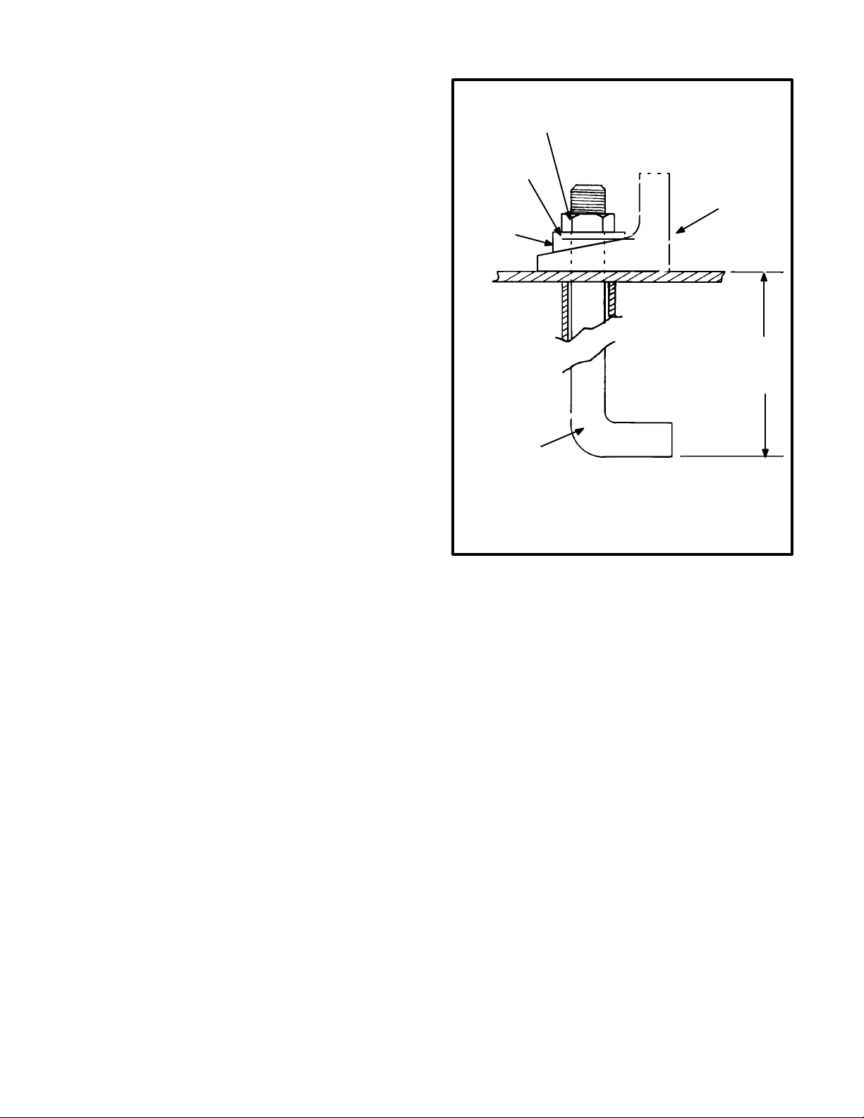
FLAT
WASHER
BEVEL
WASHER
MOUNTING
BOLT
HEX NUT
SKID
12 INCH
(305 mm)
M-1627
FIGURE 3-1. TYPICAL ANCHOR BOLT DIAGRAM
3-2
Page 12

CONDENSATION
DRAIN TAP
DC
CONTROL
WIRING
MUFFLER
THIMBLE
FLEXIBLE SEC-
TION
AIR
OUTLET
DUCT
SWEEPING
ELBOW
AC POWER WIRING
AIR
IN
M-1808
VIBRATION
ISOLATORS
CONCRETE
BASE
IMPORTANT!
COOLING AIR INLET MUST BE AT
LEAST 1-1/2 TIMES LARGER THAN
RADIATOR DUCT OUTLET AREA
ON RADIATOR COOLED MODELS
FLOW OF COOLING AIR AND
HEATED AIR CAN BE CONTROLLED
BY AUTOMATICALLY OPERATED
LOUVRES
FIGURE 3-2. TYPICAL INSTALLATION
3-3
Page 13

VIBRATION ISOLATORS
Installation and Adjustment Procedure
1. Place the isolators (Figure 3-3) on the genset
support structure. The isolators should be
shimmed or grouted to ensure that all of the isolator bases are within 0.25 inch (6 mm) elevation of each other. The surface on which the
isolator bases rest on must also be flat.
2. Loosen the side snubber lock nuts so that the
top plate of the isolator is free to move vertically
and horizontally. Be sure that the top plate is
correctly aligned with the base and springs.
3. Place the genset onto the isolators while aligning the skid’s mounting with the threaded isolator hole. The top plates will move down and approach the base of the isolator as load is applied.
4. Once the genset is in position, the isolators
may require adjusting so that the set is level.
The isolators are adjusted by inserting the leveling bolt through the skid and into the isolator
(the leveling bolt’s locking nut should be
threaded up towards the bolt head).
The leveling bolt will adjust the clearance between the top plate and the isolator base. A
nominal clearance of 0.25 inch (6 mm) or greater is desired. This will provide sufficient clearance for the rocking that occurs during startup
and shutdown. If the 0.25 inch (6 mm) clearance is not present, turn the leveling bolt until
the desired clearance is achieved.
5. The genset may not be level yet, therefore adjust the leveling bolts until the set is level and
sufficient clearance still remains. Once all isolators have been set, then lock the leveling bolt
in place with the lock nut.
6. The snubber nuts may remain loose and therefore provide better isolation between the genset and support structure.
GENSET SKID
SNUBBER
LEVELING BOLT
LOCK NUT
CLEARANCE
BASE
M1828–1s
FIGURE 3-3. VIBRATION ISOLATORS
3-4
Page 14

4. Mechanical Connections
GENERAL
The generator set mechanical system installation
includes connecting the fuel, exhaust, ventilation
and cooling systems (Figure 3-2). Before starting
any type of fuel installation, all pertinent state and
local codes must be complied with and the installation must be inspected before the unit is put in service.
FUEL SYSTEM
Cummins engines used on DF series generator
sets normally use ASTM No. 2 Diesel fuel. They will,
however, operate on alternate diesel fuels within
the specifications shown in engine manual.
In all fuel system installations, cleanliness is of the
upmost importance. Make every effort to prevent
entrance of moisture, dirt or contaminants of any
kind. Clean all fuel system components before
installing.
Use only compatible metal fuel lines to avoid electrolysis when fuel lines must be buried. Use a flexible section of tubing between the engine and fuel
supply line to provide vibration isolation. Refer to
your generator set outline drawing for sizes and
locations.
CAUTION
Never use galvanized or copper fuel
lines, fittings or fuel tanks. Condensation in the
tank and lines combines with the sulfur in diesel
fuel to produce sulfuric acid. The molecular
structure of the copper or galvanized lines or
tanks reacts with the acid and contaminates the
fuel.
An electric solenoid shutoff valve in the supply line
is recommended for all installations and required for
indoor automatic or remote starting installations.
Connect the so l enoid wires to the battery run circuit
to open the valve during genset operation.
Supply Tank
Locate the f uel t ank as close as possible to the genset and within the 5 foot (1.5 m) lift capacity of the
fuel pump. Install a fuel tank that has sufficient capacity to keep the genset operating continuously at
full load for at least 36 hours. Refer to product Specification sheet for fuel consumption data.
FUEL PUMP
WATER/SEDIMENT
SEPARATOR
INJECTOR FUEL
RETURN LINE
VENTED
FILL CAP
DAY TANK
FUEL TRANSFER
PUMP - ELECTRIC
MOTOR DRIVEN
FIGURE 4-1. TYPICAL FUEL SUPPLY INSTALLATION
FLOAT
SWITCH
LARGER
OVERFLOW
LINE
CONNECT TO
AC OUTPUT
SUPPLY
LINE
FUEL TANK
All models require a fuel return
line from injectors to tank.
VENT LINE
FILL PIPE
ES-1214-2
4-1
Page 15

WARNING
Fuel leaks create fire and explosion
hazards which can result in severe personal injury or death. Always use flexible tubing between engine and fuel supply to avoid line failure and leaks due to vibration. The fuel system
must meet applicable codes.
If the main fuel tank is installed below the lift capabilities of the standard fuel transfer pump, a transfer
tank (referred to as a day tank) and auxiliary pump
will also be required. If an overhead main fuel tank is
installed, a transfer tank and float valve will be required to prevent fuel head pressures from being
placed on the fuel system components. See Day
Tank and Figure 4-1.
Day Tank (If Used)
Fuel day tanks are used when the standard engine
fuel pump does not have the capacity to draw the
fuel from the supply tank; or the supply tank is overhead and presents problems of high fuel head pressure for the fuel return.
Supply T ank Lower Than Engine:
lation, the day tank is installed near the generator
set and within the engine fuel pump lift capability,
but below the fuel injection system. Install an auxiliary fuel pump as close as possible to the supply
tank to pump fuel from the supply tank to the day
tank. A float switch in the day tank controls operation of the auxiliary fuel pump.
With this instal-
The supply tank top must be below the day tank top
to prevent siphoning from the fuel supply to the day
tank.
Provide a return line from the engine injection system return connection to the day tank (near the top).
Provide a day tank overflow line to the supply tank in
case the float switch fails to shut off the fuel transfer
pump.
WARNING
Spilled fuel presents the hazard of
fire or explosion which can result in severe personal injury or death. Provide an overflow line
to the supply tank from the day tank.
Supply Tank Higher Than Engine:
tank near the generator set, but below the fuel injection system. Use fuel line at least as large as the fuel
pump inlet. The engine fuel return line must enter
the day tank.
Include a shutoff valve in the fuel line between the
fuel supply tank and the day tank to stop fuel flow
when the generator set is off.
Install the day
Engine Fuel Connections
Identification tags are attached to the fuel supply
line and fuel return line connections by the factory.
Flexible lines for connecting between the engine
and the stationary fuel line are supplied as standard
equipment.
4-2
Page 16

EXHAUST SYSTEM
Pipe exhaust gases to the outside of any enclosure.
Locate the exhaust outlets away from any air inlets
to avoid gases re-entering the enclosure. Exhaust
installations are subject to various detrimental conditions such as extreme heat, infrequent operation
and light loads. Regularly inspect the exhaust system both visually and audibly to see that the entire
system remains fume tight and safe for operation.
WARNING
Inhalation of exhaust gases can result in severe personal injury or death. Use extreme care during installation to provide a tight
exhaust system. Terminate exhaust pipe away
from enclosed areas, windows, doors and
vents.
Use an approved thimble (Figure 4-2) where exhaust pipes pass through wall or partitions. Refer to
NFPA 37, Section 6-3. “Stationary Combustion Engines and Gas Turbines” for accepted design practices. Build according to the code requirements in
effect at the installation site.
WARNING
Inhalation of exhaust gases can result in severe personal injury or death. Do not
use exhaust heat to warm a room, compartment
or storage area.
Rain caps are available for the discharge end of vertical exhaust pipes. The rain cap clamps onto the
end of the pipe and opens due to exhaust discharge
force from the generator set. When the generator
set is stopped, the rain cap automatically closes,
protecting the exhaust system from rain, snow, etc.
RAIN CAP
9 INCH MIN
(230 mm)
VERTICAL
HORIZONTAL
WALL OR PARTITION
FIGURE 4-2. MOUNTING EXHAUST THIMBLE
DRIP CAP
HOLES IN
END OF
INNER SLEEVE
ROOF
9 INCH MIN
(230 mm)
EXS-1036
Use a section of flexible exhaust pipe between the
engine and remainder of exhaust system. Support
exhaust system to minimize weight applied to engine exhaust outlet elbow/turbocharger connection.
CAUTION
Weight applied to the engine manifold can result in turbocharger damage. Support the muffler and exhaust piping so no
weight or stress is applied to engine exhaust el bow.
4-3
Page 17

Avoid sharp bends by using sweeping, long radius
elbows and provide adequate support for muffler
and tailpipe. Pitch a horizontal run of exhaust pipe
DOWNWARD to allow any moisture condensation
to drain away from the engine. If an exhaust pipe
must be turned upward, install a condensation trap
at the point where the rise begins (Figure 4-3).
Shield or insulate exhaust lines if there is danger of
personal contact. Allow at least 12 inches (305 mm)
of clearance if the pipes pass close to a combustible
wall or partition.
IF EXHAUST LINE MUST BE
PITCHED UPWARD, CONSTRUCT
A TRAP AT POINT OF RISE
AVOID
SHARP
BENDS
WARNING
Exhaust pipes are very hot and they
can cause severe personal injury or death from
direct contact or from fire hazard. Shield or insulate exhaust pipes if there is danger of personal contact or when routed through walls or
near other combustible materials.
VENTILATION AND COOLING
Generator sets create considerable heat that must
be removed by proper ventilation. Outdoor installations rely on natural air circulation but indoor installations need properly sized and positioned vents for
required airflow.
Vents and Ducts
For indoor installations, locate vents so incoming air
passes through the immediate area of the installation before exhausting. Install the air outlet higher
than the air inlet to allow for convection air movement.
Size the vents and ducts so they are large enough to
allow the required flow rate of air . The “free area” of
ducts must be as large as the exposed area of the
radiator. Refer to the DF series Product Data
Sheets for the airflow requirements.
DRAIN CONDENSATION
TRAP PERIODICALLY
EXS-1046s
FIGURE 4-3. CONDENSATION TRAP
Wind will restrict free airflow if it blows directly into
the air outlet vent. Locate the outlet vent so the effects of wind are eliminated. See Figure 4-4.
For operation outside a building, a shelter housing
with electrically operated louvers is available as an
option. T ransformers connected across the generator output supply current to the motors.
CS-1366
FIGURE 4-4. WIND BARRIER
4-4
Page 18

Dampers
Dampers or louvers protect the genset and equipment room from the outside environment. Their operation of opening and closing should be controlled
by operation of the genset.
In cooler climates movable or discharge dampers
are used. These dampers allow the air to be recirculated back to the equipment room. This enables the
equipment room to be heated while the genset engine is still cold, increasing the engine efficiency.
Radiator Set Requirements
Radiator set cooling air is drawn past the rear of the
set by a pusher fan that blows air through the radiator (Figure 4-5). Locate the air inlet to the rear of the
set. Make the inlet vent opening 1-1/2 times larger
than the radiator area.
Locate the cooling air outlet directly in front of the radiator and as close as possible. The outlet opening
must be at least as large as the radiator area.
Length and shape of the air outlet duct should offer
minimum restriction to airflow.
The radiator has an air discharge duct adapter
flange. Attach a canvas or sheet metal duct to the
flange and the air outlet opening using screws and
nuts so duct can be removed for maintenance purposes. The duct prevents circulation of heated air.
Before installing the duct, remove the radiator core
guard.
Standard Radiator Cooling uses a set mounted
radiator and engine pusher fan to cool engine water
jacket. Air travels from the generator end of the set,
across the engine and out through the radiator. An
integral discharge duct adapter flange surrounds
the radiator grille.
Remote Radiator Cooling (Optional) substitutes
a remote mounted radiator and an electrically driven fan for the set mounted components. Removal of
the radiator and the fan from the set reduces noise
levels without forcing dependence on a continuous
cooling water supply. The remote radiator installation must be completely protected against freezing.
Remote radiator plumbing will vary with installation.
Follow recommendations given in Application
Manual T-030. See product data sheet for friction
head and static head limits.
Before filling cooling system, check all hardware for
security. This includes hose clamps, capscrews, fittings and connections. Use flexible coolant lines
with heat exchanger, standpipe or remote mounted
radiator.
INLET
AIR
DAMPER
COOL
AIR
* Louvers should close when
room ambient is above 60
° C)
(16
° F
FIGURE 4-5. TYPICAL RADIATOR SET INSTALLATION
THERMOSTATIC AIR
RECIRCULATING
DAMPER *
RADIATOR
FLEXIBLE DUCT
CONNECTOR
WIND/
NOISE
BARRIER
HOT
AIR
D
DISTANCE SHOULD NOT
BE LESS THAN HEIGHT
OF RADIATOR
CS-1382c
4-5
Page 19

Water Jacket Heater (Optional)
An optional water jacket heater can be installed to
keep the engine warm for starting under adverse
weather conditions. Connect the heater to a power
source that will be on when the engine is NOT running.
Heat Exchanger (Optional)
The optional heat exchanger (Figure 4-6) uses a
shell and tube type heat exchanger instead of the
standard radiator and fan. Engine jacket coolant circulates through the shell side of the heat exchanger
while the cooling water is pumped through the
tubes. Engine coolant and raw water do not mix.
This type of cooling separation is necessary when
the raw water contains scale forming lime or other
impurities.
This system can reduce set enclosure airflow requirements and noise levels. Proper operation depends on a constant supply of raw water for heat removal. Adjust the flow to maintain engine coolant
temperature between165
° C) while viewing the water temperature gauge.
91
° F and 195° F (74° C and
The engine coolant side of the system can be protected from freezing; the raw water side cannot be
protected.
VENTILATING
FAN
COOL AIR
WATER
SOLENOID
VALVE
FIGURE 4-6. TYPICAL HEAT EXCHANGER INSTALLATION
WARM
AIR
FLEXIBLE WA-
TER
CONNECTIONS
MOUNTED HEAT
EXCHANGER
RAW WATER
SUPPLY
RAW WATER
DISCHARGE
4-6
Page 20

Coolant Filter
One spin-on type corrosion filter (Figure 4-7) is
standard equipment. This precharge filter is compatible with plain water and all ethylene glycol base
permanent antifreeze coolants. Refer to engine
manufacturer’s manual for instructions if a methoxy
propanal base antifreeze is desired. Replace filter
periodically as recommended in the
Maintenance
section of the Operator’s manual.
Coolant Heater
A coolant heater is used to keep the engine coolant
warm when the engine is shut down. It heats and circulates the coolant within the engine. This reduces
startup time and lessens engine wear caused by
cold starts. It is electrically operated and thermostatically controlled.
COOLANT
FILTER
SHUTOFF
VALVES
FILTER
WARNING
The coolant heater must not be operated while the cooling system is empty or
when the engine is running or damage to the
heater will occur.
Figure 4-8 shows the heater line connections. Connect the heater to a source of power that will be on
during the time the engine is not running. Be sure
the voltage rating is correct for the heater element
rating.
NOTE: OPEN COOLANT FILTER SHUTOFF VALVES
BEFORE OPERATING GENERATOR SET.
CS-1198
FIGURE 4-7. TYPICAL COOLANT FILTER
THERMOSTAT
1/2 NPT
OUTLET
(FOR 1” ID HOSE)
DRAIN
4-7
INLET
(FOR 1” ID HOSE)
CS-1367
FIGURE 4-8. TYPICAL COOLANT HEATER
Page 21

4-8
Page 22

5. Electrical Connections
GENERAL
The genset electrical system includes connecting
the load, installing the control wiring and connecting
the batteries. Connect the batteries last to avoid accidental starting of the unit during installation.
WARNING
Accidental starting of the generator
set while working on it can cause severe personal injury or death. Prevent accidental starting by disconnecting the starting battery cables
(negative [–] first).
Arcing can ignite the explosive hydrogen gas
given off by batteries, causing severe personal
injury. Arcing can occur if the negative (–) battery cable is connected and a tool being used to
connect or disconnect the positive (+) battery
cable accidentally touches the frame or other
grounded metal part of the set. To prevent arcing, always remove the negative (–) cable first,
and reconnect it last.
CAUTION
To prevent arcing, always disconnect a battery charger from its AC source before
disconnecting the battery cables. Otherwise,
disconnecting the cables can result in voltage
spikes high enough to damage the DC control
circuits of the set.
LOAD
NORMAL
SOURCE
NOTE: SHOWN WITH LINE
CONNECTED TO LOAD
FIGURE 5-1. TYPICAL LOAD TRANSFER SWITCH
GENSET
SC-1101-1
Most local regulations require that wiring connections be made by a licensed electrician and the
installation be inspected and approved before operation. All connections, wire sizes, etc. must conform to the requirements of all electrical codes in effect at the installation site.
WARNING
Improper wiring can cause a fire or
electrocution, resulting in severe personal injury or death and/or property and equipment damage.
TRANSFER SWITCH
If the installation is for standby service, a transfer
switch is required for switching the load from the
normal power source to the generator set (Figure
5-1). Either a manual or automatic switch can be
used. Follow the installation instructions provided
with the transfer switch when connecting the load
and control wiring.
5-1
Page 23

AC WIRING
Generator Voltage Connections
The generator output voltage and maximum current
rating are specified on the generator set nameplate.
Line-to-neutral voltage is always the lower voltage
shown and line-to-line voltage is the higher rating.
These generators can be configured for the voltages shown in
these voltages must be reconnected by the installer
to give the voltage required by the installation. Before shipping, the factory tests the generator set
output by connecting the generator to produce a
particular test voltage. The generator may be connected at the factory to produce a specified voltage
per customer order. The installer must always
check the stator lead terminal block connections
and perform any necessary reconnect to obtain the
voltage desired.
Wiring Diagram
section. Most of
ers are labeled CT21, CT22 and CT23 on the wiring
diagram. Refer to
fy the output leads that must be routed through each
current transformer, and also appropriate transformer post selection for meter lead harness connection. Use cable ties to secure the loose transformers to the generator output leads.
Wiring Diagram
section to identi-
Load Balancing
When connecting loads to the generator set, balance the loads so the current flow from each line terminal (L1, L2 and L3) is about the same. This is especially important if both single phase and three
phase loads are connected. Any combination of
single phase and three phase loading can be used
as long as each line current is about the same, within 10 percent of median value and no line current
exceeds the nameplate rating of the generator.
Check the current flow from each line after connections by observing the control panel ammeter.
Refer to
the voltage connection information; and use the
electrical schematic supplied with your generator
set when actually performing load connections.
CAUTION
Wiring Diagram
section when reviewing
Reconnecting factory connected
generator sets to lower voltages can reduce se t
ratings, and also render line circuit breakers too
small. Consult with your distributor before performing reconnection for a different voltage.
Load Connections
Connecting the Load:
the generator by bolting the load wires to the appropriate terminals on the generator terminal block.
The terminals are stamped U, V, W and N to indicate
the line and neutral connections. (Reference: U, V,
and W correspond with L1, L2 and L3; and N with L0
respectively).
When installing sets with AC meters, the generator
output leads must be routed through current transformers for proper meter operation. The transform-
All loads are connected to
Grounding
Grounding involves making a conducting connection between the metal parts of the generator set or
one of its electrical circuits and the earth. The design and installation of a grounding system is affected by many factors such as the use of multiple
transformers, ground fault protection requirements
and physical location of the generator. Follow the
recommendations of the consulting engineer when
installing the grounding system.
WARNING
can result in severe personal injury or death. It
is extremely important that bonding and equipment grounding be properly done. All metallic
parts that could become energized under abnormal conditions must be properly grounded.
Typical requirements for bonding and grounding
are given in the National Electrical Code, Article
250. All connections, wire sizes, etc. must conform
to the requirements of the electrical codes in effect
at the installation site.
Contact with electrical equipment
5-2
Page 24

DC WIRING
Remote Control Connections
inducing currents that could cause problems within
the control.
Provisions are made inside the control box for adding optional remote starting stations and alarms.
Connections are made on the terminal block (TB1)
located on the engine monitor circuit board (A11).
Connect one or more remote switches across remote terminal and B+ terminal. Refer to Figure 5-2.
If the distance between the generator set and remote stations is less than 1000 feet (305 m), use 18
gauge stranded copper wire. If the distance is 1000
to 2000 feet (305 to 610 m), use 16 gauge stranded
copper wire. Always run control circuit wiring in a
separate conduit from the AC power cables to avoid
TB1
7
B+ (DC POWER)
6
RMT (REMOTE START)
5
GND (GROUND)
4
ALM (COMMON ALARM)
CONTROL
PANEL BOX
TB1
Remote Monitor Connections
Provisions are made inside the control box for adding optional remote monitoring on these gensets
employing optional Detector 12 (12 lamp panel).
Connections are made on the terminal block (TB2)
located on the engine monitor circuit board A11. Refer to Figure 5-2.
CAUTION
the same conduit as the AC power. AC voltage
induced currents can create operational problems with electronic solid-state devices.
ENGINE
CONTROL
MONITOR
A11
Do not install DC control wiring in
TB2
10
11
12
13
14
15
16
1
2
3
4
5
6
7
8
9
FAULT 2 - INPUT
FAULT 2 - OUTPUT
FAULT 1 - INPUT
FAULT 1 - OUTPUT
LAMP TEST/RESET
OVERCRANK
OVERSPEED
HIGH ENGINE TEMPERATURE
LOW OIL PRESSURE
PRE-HIGH ENGINE TEMPERATURE
PRE-LOW OIL PRESSURE
SWITCH OFF
LOW ENGINE TEMPERATURE
LOW FUEL - INPUT
LOW FUEL - OUTPUT
SHUTDOWN
NON-TIMED
SHUTDOWN
TIMED
SHUTDOWN
GROUND STUD
(USE GROUND
STUD OR A11-TB1-5
FOR CONTROL
GROUND WIRES)
FIGURE 5-2. REMOTE CONTROL AND REMOTE MONITOR CONNECTION POINTS
A13 A14
INTERFACE
RELAY MODULES
5-3
TB2
ES-1561
Page 25

Battery Connections
Starting the unit requires 24 volt battery current.
Use two, 12 volt (Type 8D) batteries for a normal
installation (Figure 5-3). Connect the batteries in
series (negative post of first battery to the positive
post of the second battery) as shown in Figure 5-3.
Necessary battery cables and rack are on the unit.
Service batteries as necessary. Infrequent use (as
in emergency standby service), may allow battery
to self-discharge to the point where it cannot start
the unit. If installing an automatic transfer switch
that has no built-in charge circuit, connect a separate trickle charger. Onan automatic transfer
switches include such a battery charging circuit.
WARNING
Ignition of explosive battery gases
can cause severe personal injury. Always connect battery negative last to prevent arcing.
WARNING
Do not smoke while servicing the
batteries. Explosive gases are emitted from batteries in operation. Ignition of these gases can
cause severe personal injury.
Control Heater (Optional)
A control heater provides a means of humidity/temperature control of the control box interior. It protects the components and ensures their effectiveness when the generator set is subjected to varying
ambient air conditions during extended periods of
non-use. The element is controlled by an adjustable
thermostat (Figure 5-4).
POSITIVE
NEGATIVE
TWO, 12 VOLT
BATTERIES
ES-1865–1s
FIGURE 5-3. BATTERY CONNECTIONS
THERMOSTAT
TO 120 VAC
SUPPLY
5-4
HEATER
ELEMENT
ES-1563s–3
FIGURE 5-4. OPTIONAL CONTROL HEATER
Page 26

6. Prestart Preparation
GENERAL
Before attempting the initial starting of the generator set, be sure it is serviced and ready for operation
(Figure 6-1). Perform the following:
• Check ventilation and exhaust systems
• Check all mechanical connections
• Fill the coolant, lubrication and fuel systems
• Prime the lubrication and fuel systems
• Check the fuel system for leaks
• Check the lubrication system for leaks
VENTILATION
Verify all air vents and ducts are open and free from
any obstructions. Verify dampers, if used, operate
properly.
EXHAUST SYSTEM
Check the exhaust system for proper installation.
Verify there is at least 12 inches (305 mm) clearance between exhaust pipes and combustible materials, and all connections are tight.
MECHANICAL CHECKS
Check the generator set for loose or damaged components and repair or replace as required.
ELECTRICAL SYSTEM
Verify all electrical connections are secure and all
wiring is complete and inspected. Replace and secure any access panels that may have been removed during installation.
Load Connections
Check that load cables from generator set are properly connected to either a transfer switch or circuit
breaker panel.
EXHAUST
SYSTEM
AIR OUTLET
• FILL COOLANT SYSTEM
• FILL AND PRIME LUBRICATION SYSTEM
• FILL AND PRIME FUEL SYSTEM
FIGURE 6-1. TYPICAL INSTALLATION
AIR INLET
CHECK THAT ALL ASPECTS
OF INSTALLATION ARE
READY FOR OPERATION
M-1808
6-1
Page 27

Battery Connections
4
Use two 12 volt batteries for a normal installation.
Connect the negative (-) battery cable last to reduce
the risk of arcing.
Service the batteries as necessary. If an automatic
transfer switch is not used or installed without a
built-in charge circuit, connect a separate float charger to the battery.
OIL SUPPLY INLET
LINE. DISCONNECT AT
THIS POINT TO PRIME
COOLANT
Engine coolant is drained prior to shipment. Before
starting, fill the cooling system with the recommended coolant. See Operator’s manual
nance
section for more information.
Mainte-
LUBRICATION
Engine oil is drained prior to shipment. Before starting, fill and prime the lubrication system as follows:
1. Remove oil inlet line from turbocharger housing (Figure 6-2), fill bearing housing with clean
engine lubricating oil; replace line and secure.
2. Fill crankcase to “L” (low) mark on dipstick (Figure 6-3) and refer to
Operator’s manual for oil recommendations.
3. Remove plug from head of oil filter housing.
Connect a hand or motor driven priming pump,
equipped with pressure gauge, from a source
of clean lubricating oil to the plug boss in the filter housing.
4. Prime until a 30 psi (207 kPa) pressure is obtained.
5. Disconnect wire from fuel solenoid valve (Figure 6-4).
6. On the engine control panel, depress the RUN
switch to crank the engine, while maintaining
an oil priming pressure of 15 psi (103 kPa) for
15 seconds, at filter head priming port.
7. Stop engine cranking, remove external priming
equipment, reinstall plug in filter housing and
torque to 15 to 20 ft lb (20 to 27 N
8. Reconnect wire to fuel solenoid valve.
9. Complete oil fill to “H” (high) mark on dipstick.
Maintenance
section in
•m).
TURBOCHARGER
HOUSING
PRIMING
PLUG
OIL
FILTER
B-342-3s
FIGURE 6-2. PRIMING TURBOCHARGER
OIL
DIPSTICK
STARTER
B342–7s
FIGURE 6-3. OIL DIPSTICK LOCATION
B3
6-2
Page 28

FUEL
Fill the fuel tanks with the recommended fuel. Engine fuel may not be primed at the fuel filters after
shipment. To verify and reprime the fuel system perform the following procedure:
1. Remove each fuel filter and fill with clean fuel
(Figure 6-5).
CAUTION
Due to the precise tolerances of
diesel injection systems, it is extremely important the fuel be kept clean and free of
water. Dirt or water in the system can cause
severe damage to both the injection pump
and the injection nozzles.
2. Put a light coat of fuel on the sealing gasket.
3. Install and tighten by hand until the gasket just
touches the filter head.
4. Tighten the filter an additional one-half to threefourths turn.
FUEL SOLENOID
FS1692s
FIGURE 6-4. FUEL SOLENOID VALVE LOCATION
FUEL SUPPLY
INLET
FIGURE 6-5. FUEL FILTERS
SUPPLY LINE,
FILTER TO
INJECTION
PUMP
FUEL FILTERS
FS1803s
6-3
Page 29

6-4
Page 30

7. Initial Start and Checks
Before putting the generator set under load conditions, verify the set will perform correctly by checking the following areas.
STARTING
Move the Run/Stop/Remote switch on the engine
control panel to the Run position. The starter should
crank the engine and the engine should start within
a few seconds. If after a few seconds of cranking the
engine fails to start or starts, runs and then stops,
refer to Troubleshooting charts in the Operator’s
Manual.
ENGINE GAUGES
Check the following while the genset is operating:
Oil Pressure Gauge
The oil pressure should be in the range of 40 to 60
psi (275 to 414 kPa) when the engine is at operating
temperature.
Water Temperature Gauge
Frequency Meter
The generator frequency should be stable and the
reading should be the same as the nameplate rating
(50 or 60 hertz).
AC Voltmeter
Turn the phase selector switch to each line-to-line
phase selection shown on the volts scale (L1-L2 on
single phase sets; L1-L2, L2-L3 and L3-L1 on three
phase sets). Read the AC voltmeter using the upper
or lower scale as indicated by the scale indicator
light. At no load, the line-to-line voltage should be
the same as the set nameplate rating.
AC Ammeter
Turn the phase selector switch to each phase selection shown on the amperes scale (L1and L2 on
single phase sets; L1, L2 and L3 on three phase
sets). Read the ammeter using the upper or lower
scale as indicated by the scale indicator light. At no
load, the current readings should be zero. With a
load applied, each line current should be approximately the same and no line current should exceed
the set nameplate reading.
ENGINE MONITOR INDICATOR LAMPS
The water temperature should be in the range of
° to 195°F (74° to 91°C) depending on the load
165
and ambient temperature.
DC Voltmeter
This is a voltage reference gauge, indicating condition of the batteries and also of the battery charging
circuit. Gauge should read approximately 24 to 28
volts while set is running. If reading is high or low,
check batteries and the battery charging circuit.
AC METERS (IF EQUIPPED)
Note the AC instruments on the control panel. The
frequency meter and voltmeter should indicate
rated nameplate frequency and voltage. Turn the
control panel Voltage Adjust control (if equipped) for
nameplate voltage. Use the Phase Selector Switch
to read each of the line-to-line voltages.
Move the Run/Stop/Remote switch on the engine
panel to the Stop position. Hold the Reset/Lamp
Test switch in the Test position. All indicator lamps
should light. Verify all the lamps are on and then release the switch. Contact your authorized service
center if any lamps require replacement.
EXHAUST SYSTEM
With the genset operating, inspect the entire exhaust system including the exhaust manifold, muffler, turbocharger and exhaust pipe. Visually and
audibly check for leaks at all connections, welds,
gaskets and joints. Make sure exhaust pipes are not
heating surrounding areas excessively . If any leaks
are detected, have them corrected immediately.
WARNING
sult in severe injury or death. Inspect exhaust
system visually and audibly for leaks daily. Repair any leaks immediately.
Inhalation of exhaust gases can re-
7-1
Page 31

FUEL SYSTEM
With the genset operating, inspect the fuel supply
lines, filters and fittings for leaks. Check any flexible
sections for cuts, cracks and abrasions and make
sure they are not rubbing against anything that
could cause breakage.
WARNING
that can result in severe personal injury or
death if ignited by a spark. If any leaks are detected, have them corrected immediately.
Leaking fuel will create a fire hazard
WARNING
Ignition of explosive gases can
cause explosion and fire, resulting in severe
personal injury or death. Do not smoke while
servicing the batteries.
COOLING SYSTEM
When the engine is first started, remove the radiator
pressure cap and monitor the coolant level. As
trapped air is expelled from the system, the coolant
level will drop and additional coolant must be added. Replace the pressure cap when the coolant level is stable.
MECHANICAL ADJUSTMENTS
DC ELECTRICAL SYSTEM
With the generator set off, check the terminals on
the battery for clean and tight connections. Loose or
corroded connections create resistance that can
hinder starting. Clean and reconnect the battery
cables if loose. Always connect the negative battery
cable last.
EXCITATION
AC VOLTMETER
AC AMMETER
FIELD
BREAKER
VOLTAGE
ADJUST
UPPER AND
LOWER SCALE
INDICATOR LAMPS
With the generator stopped, check for loose belts
and fittings, leaking gaskets and hoses, or any
signs of mechanical damage. If any problems are
found, have them corrected immediately.
With the set running, listen for any unusual noises
that can indicate mechanical problems. Check the
oil pressure frequently. Refer to Operator’s or Service Manual for required adjustments.
OIL PRESSURE
GAUGE
RUN-STOP-REMOTE
SWITCH
PANEL LAMP
RESET, LAMP TEST,
PANEL LAMP SWITCH
INDICATOR
LAMPS
COOLANT
TEMPERATURE
GAUGE
PHASE SELECTOR
SWITCH
FREQUENCY METER
WATTMETER
OTHER
OPTIONAL
METERS
FIGURE 7-1. CONTROL PANEL WITH OPTIONS
OIL TEMP
GAUGE
7-2
TACHOMETER
DC VOLTMETER
FREQUENCY
ADJUST
RUNNING TIME
METER
EMERGENCY STOP
PUSHBUTTON
Page 32

8. Wiring Diagrams
Reconnectible Voltages 8-3. . . . . . . . . . . . . . . . . . . . . . . . . . . . . . . . . . . . . . . . . . . . . . . . . . . . . . . . . . . . . . . . . .
Non-reconnectible Voltages 8-4. . . . . . . . . . . . . . . . . . . . . . . . . . . . . . . . . . . . . . . . . . . . . . . . . . . . . . . . . . . . . . .
8-1
Page 33

8-2
Page 34

RECONNECIBLE VOLTAGES
8-3
No. 625-2165 Sh 1 of 2
Rev. J Sys: Revisio
Modified 2/1994
Page 35

NON-RECONNECIBLE VOLTAGES
8-4
No. 625-2165 Sh 2 of 2
Rev. J Sys: Revisio
Modified 2/1994
Page 36

Cummins Power Generation
1400 73rd Avenue N.E.
Minneapolis, MN 55432
1-800-888-6626
763-574-5000 International Use
Fax: 763-528-7229
Cummins is a registered trademark of Cummins Inc.
 Loading...