

CUMMINS CFP83 SERIES, CFP83-F10, CFP83-F20, CFP83-F30, CFP83-F40 Operation & Maintenance Manual
CFP83 SERIES
Operation & Maintenance Manual
Fire Pump Drive Engines
www.cumminsfirepower.com

Page ii
Foreword
This manual contains information for the correct operation and maintenance of a Cummins Fire Pump engine.
It also includes important safety information, engine and systems specifications, troubleshooting guidelines, and
listings of Cummins Authorized Repair Locations.
Read and follow all safety instructions. Refer to the General Safety Instructions
Keep this manual with the equipment. If the equipment is traded or sold, give the manual to the new owner.
The information, specifications, and recommended maintenance guidelines in this manual are based on
information in effect at the time of printing. Cummins Fire Power, Cummins NPower and Cummins Engine
Company, Inc. reserve the right to make changes at any time without obligation. If any differences are found
between an engine and the information in this manual, contact the local Cummins Authorized Repair Location.
The latest technology and the highest quality components were used to produce this engine. When replacement
parts are needed, we recommend using only genuine Cummins or ReCon® exchange parts. These parts can be
identified by the following trademarks:
NOTE: Warranty information is located in Section 11. Make sure you are familiar with the warranty or warranties
applicable to your engine.
in Section 1.
© 2005 Cummins Inc., Box 3005, Columbus, IN 47202-3005 U.S.A.
Drawing No. 9777, Section 0, Rev. 02-07

Page iii
Index of Sections
Introduction ………………………………………………………………….……………….......................................... 1
Engine Identification …………………………………………………………………………… ................................... 2
Installation and Operation ………………………………………………………….………….. .................................. 3
Maintenance Guidelines ……………………………………………………….…………...........................................4
Maintenance Procedures ……………………………………………………………..................................................5
System Diagrams …………………………………………………………………………... ......................................... 6
Adjustment, Replace and Replacement……………………………............................... ....................................... 7
Service Literature …………………………………………………………………………… ........................................ 8
Service Assistance ………..………………………………………………………………... ........................................ 9
Maintenance Specifications ……………………………………............................................................................ 10
Warranty Information…………………………………………………………………………………….. ....................11
Troubleshooting …………………………………………………………………………….. ......................................12
Assembly Drawings…………………………………………………………………………. ...................................... 13
Drawing No. 9777, Section 0, Rev. 02-07

Page iv
THIS PAGE INTENTIONALLY LET BLANK
Drawing No. 9777, Section 0, Rev. 02-07

Section 1 – Introduction Page 1-1
CFP83 Series
Section 1 – Introduction
Section Contents
Page
To the Owner and Operator .............................................................................................................1-3
About the Manual..............................................................................................................................1-3
How to Use the Manual ....................................................................................................................1-3
Symbols .............................................................................................................................................1-4
Illustrations .......................................................................................................................................1-5
General Safety Instructions.............................................................................................................1-6
General Cleaning Instructions ........................................................................................................1-8
Acronyms and Abbreviations..........................................................................................................1-14
Drawing No. 9777, Section 1, Rev. 02-07

Page 1-2 Section 1 – Introduction
CFP83 Series
THIS PAGE INTENTIONALLY LEFT BLANK
Drawing No. 9777, Section 1, Rev. 02-07

Section 1 – Introduction Page 1-3
CFP83 Series
To the Owner and Operator
Preventative maintenance is the easiest and least expensive type of maintenance. Follow the maintenance
schedule recommendations outlined in Maintenance Guidelines
Keep records of regularly scheduled maintenance.
in Section 4.
Use the correct fuel, oil, coolant, and filters in the engine as specified in Maintenance Specifications
10.
Cummins Fire Power, Cummins NPower and Cummins Engine Company, Inc use the latest technology and the
highest quality components to produce its engines. Cummins recommends using only genuine Cummins parts.
Personnel at Cummins Authorized Repair Locations have been trained to provide expert service and parts
support. If a problem that can not be resolved by a Cummins Authorized Repair Location occurs, follow the
steps outlined in the Service Assistance
in Section 9.
in Section
About the Manual
This manual contains information needed to operate and maintain an engine correctly as recommended by
Cummins Fire Power, Cummins NPower and Cummins Engine Company, Inc. Additional service literature
(troubleshooting and repair manual) can be ordered by filling out and mailing the Literature Order Form located
in Service Literature
Both metric and U.S. customary values are listed in this manual. The metric value is listed first, followed by the
U.S. customary in brackets.
Numerous illustrations and symbols are used to aid in understanding the meaning of the text. Refer to the
Symbols
Each section is preceded by a Section Contents to aid in locating information more quickly.
subsection in this section for a complete listing of symbols and their definitions.
in Section 8.
How to Use the Manual
This manual is organized according to intervals at which maintenance on the engine is to be performed. A table
that states the required intervals and the checks to be made is located in Section 4. Locate the interval at which
maintenance will be performed, then follow the steps given in the referenced section for all the procedures to be
performed. All the procedures done under previous maintenance intervals must be performed, also.
Keep a record of all the checks and inspections made. A record form for recording date, mileage/kilometer or
hours, and which maintenance checks were performed is located in Section 4.
Refer to the Maintenance Specifications
Company, Inc., for your engine. Specifications and torque values for each engine system are given in that
section.
Drawing No. 9777, Section 1, Rev. 02-07
in Section 10 for specifications recommended by Cummins Engine
Page 1-4 Section 1 – Introduction
CFP83 Series
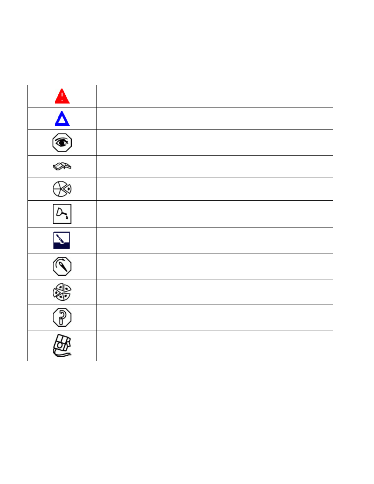
Symbols
The following symbols have been used in this manual to help communicate the intent of the instructions. When
one of the symbols appears, it conveys the meaning define below:
WARNING. Serious personal injury or extensive property damage can result if the
warning instructions are not followed.
CAUTION. Minor personal injury can result or a part, an assembly, or the engine can
be damaged if the caution instructions are not followed.
INSPECTION is required.
Refer to another location in this manual or another publication for additional
information.
Indicates a REMOVAL or DISASSEMBLY step
LUBRICATE the part or assembly.
CLEAN the part or assembly.
TIGHTEN to a specific torque.
Indicates an INSTALLATION or an ASSEMBLY step
PERFORM a mechanical or time MEASUREMENT.
PERFORM an electrical MEASUREMENT.
Drawing No. 9777, Section 1, Rev. 02-07
Section 1 – Introduction Page 1-5
CFP83 Series
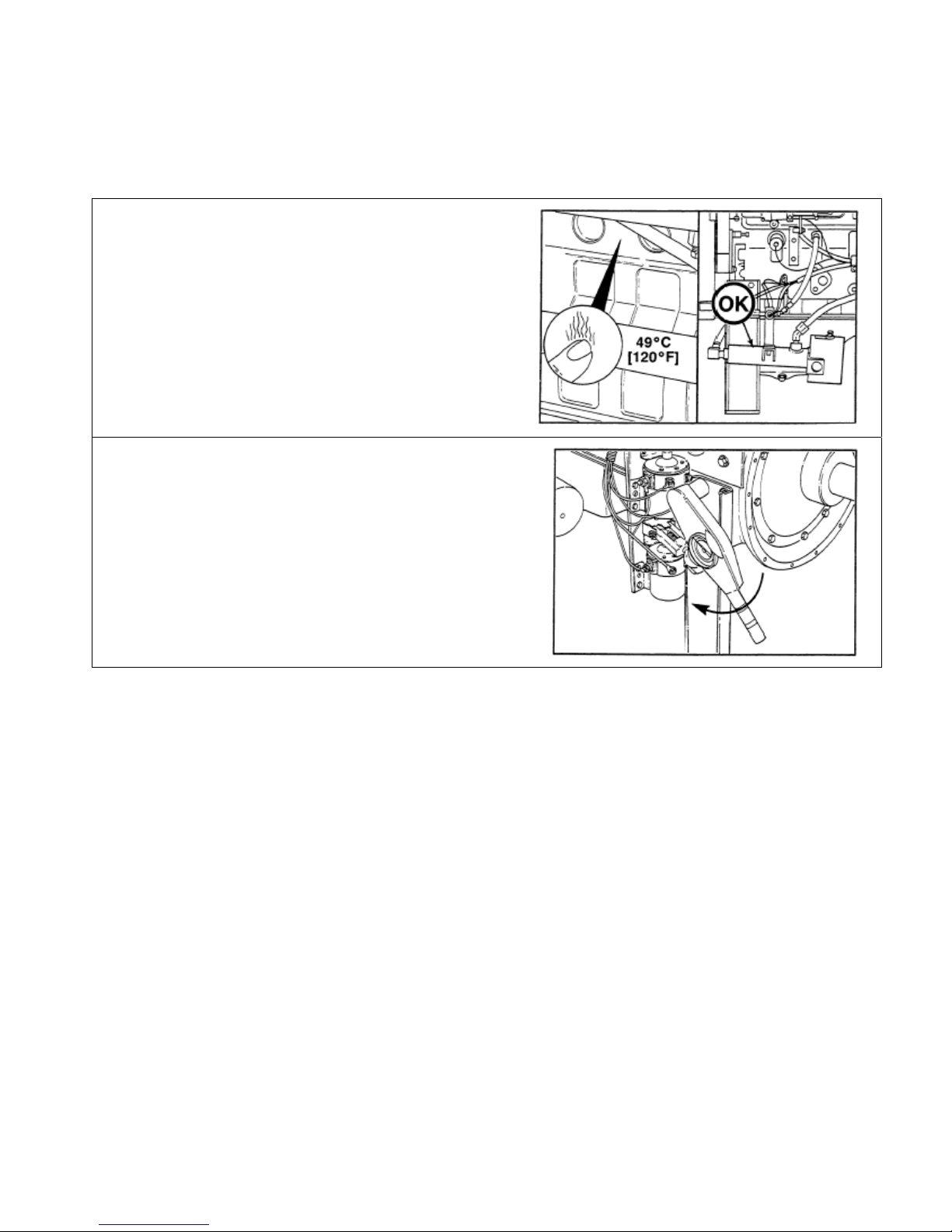
Illustrations
The illustrations used in this manual are
intended to give an example of a problem, and
to show what to look for and where the problem
can be found.
Some of the illustrations are “generic” and might
not look exactly like the engine or parts used in
your application.
The illustrations can contain symbols to indicate
an action required, and an acceptable or not
acceptable condition.
The illustrations are also intended to show
repair or replacement procedures.
The illustration can differ from your application,
but the procedure given will be the same.
Drawing No. 9777, Section 1, Rev. 02-07

Page 1-6 Section 1 – Introduction
CFP83 Series
General Safety Instructions
WARNING
Improper practices or carelessness can cause burns, cuts, mutilation, asphyxiation or other bodily
injury or death.
• Read and understand all of the safety precautions and warnings before performing any repair. This list
contains the general safety precautions that must be followed to provide personal safety. Special safety
precautions are included in the procedures when they apply.
• Make sure the work area surrounding the product is dry, well lit, ventilated; free from clutter, loose tools,
parts, ignition sources and hazardous substances. Be aware of hazardous conditions that can exist.
• Always wear protective glasses and protective shoes when working.
• Rotating parts can cause cuts, mutilation or strangulation.
• Do not wear loose-fitting or torn clothing. Remove all jewelry when working.
• Disconnect the battery (negative [-] cable first) and discharge any capacitors before beginning any repair
work. Put a "Do Not Operate" tag on the controls.
• Use ONLY the proper engine barring techniques for manually rotating the engine. Do not attempt to rotate
the crankshaft by pulling or prying on the fan. This practice can cause serious personal injury, property
damage, or damage to the fan blade(s) causing premature fan failure.
• If an engine has been operating and the coolant is hot, allow the engine to cool before you slowly loosen the
filler cap and relieve the pressure from the cooling system.
• Do not work on anything that is supported ONLY by lifting jacks or a hoist. Always use blocks or proper
stands to support the product before performing any service work.
• Relieve all pressure in the air, oil, and the cooling systems before any lines, fittings, or related items are
removed or disconnected. Be alert for possible pressure when disconnecting any device from a system that
utilizes pressure. Do not check for pressure leaks with your hand. High pressure oil or fuel can cause
personal injury.
• To avoid personal injury, use a hoist or get assistance when lifting components that weigh 23 kg [50 lb] or
more. Make sure all lifting devices such as chains, hooks, or slings are in good condition and are of the
correct capacity. Make sure hooks are positioned correctly. Always use a spreader bar when necessary.
The lifting hooks must not be side-loaded.
• Corrosion inhibitor contains alkali. Do not get the substance in your eyes. Avoid prolonged or repeated
contact with skin. Do not swallow internally. In case of contact, immediately wash skin with soap and water.
In case of contact, immediately flood eyes with large amounts of water for a minimum of 15 minutes.
IMMEDIATELY CALL A PHYSICIAN. KEEP OUT OF REACH OF CHILDREN.
Drawing No. 9777, Section 1, Rev. 02-07

Section 1 – Introduction Page 1-7
CFP83 Series
General Safety Instructions (Cont.)
• Naphtha and Methyl Ethyl Ketone (MEK) are flammable materials and must be used with caution. Follow the
manufacturer's instructions to provide complete safety when using these materials. KEEP OUT OF REACH
OF CHILDREN.
• To avoid burns, be alert for hot parts on products that have just been turned OFF, and hot fluids in lines,
tubes, and compartments.
• Always use tools that are in good condition. Make sure you understand how to use them before performing
any service work. Use ONLY genuine Cummins or Cummins ReCon® replacement parts.
• Always use the same fastener part number (or equivalent) when replacing fasteners. Do not use a fastener
of lesser quality if replacements are necessary.
• Do not perform any repair when fatigued or after consuming alcohol or drugs that can impair your
functioning.
• Some state and federal agencies in the United States of America have determined that used engine oil can
be carcinogenic and can cause reproductive toxicity. Avoid inhalation of vapors, ingestion, and prolonged
contact with used engine oil. Dispose of waste oil in accordance with applicable requirements.
Drawing No. 9777, Section 1, Rev. 02-07

Page 1-8 Section 1 – Introduction
CFP83 Series
General Cleaning Instructions
WARNING
Abrasive material must be kept out of or removed from oil passages and parts wear points. Abrasive
material in oil passages can cause bearing and bushing failures that can progress to major component
damage beyond reuse. This is particularly true of main and rod bearings.
WARNING
Excessive sanding or grinding the carbon ring from the top of the cylinder liners can damage the liner
beyond reuse. The surface finish will be damaged and abrasive particles can be forced into the liner
material which can cause early cylinder wear-out or piston ring failures.
WARNING
When using solvents, acids, or alkaline materials for cleaning, follow the manufacturer’s
recommendations for use. Wear goggles and protective clothing to reduce the possibility of personal
injury.
WARNING
When using a steam cleaner, wear safety glasses or a face shield, as well as protective clothing. Hot
steam can cause serious personal injury.
CAUTION
Do not use bead blasting cleaning methods on aluminum pistons skirts or the pin bores in any piston,
piston skirt or piston crown. Small particles of the media will embed in the aluminum or other soft metal
and result in premature wear of the cylinder liner, piston rings, pins and pin bores. Valves, turbocharger
shafts, etc., can also be damaged. Follow the cleaning directions listed in the procedures.
CAUTION
Do not contaminate wash tanks and tank type solvent cleaners with the foreign material and plastic
beads. Remove the foreign material and plastic beads with compressed air, hot high pressure water or
steam before placing them in tanks or cleaners. The foreign material and plastic beads can contaminate
the tank and any other engine parts cleaned in the tank. Contaminated parts may cause failures from
abrasive wear.
CAUTION
The bead blasting operation must not disturb the metal surface. If the metal surface is disturbed the
engine can be damaged due to increased parts clearance or inadequate surface finish on parts that
move against other parts.
Drawing No. 9777, Section 1, Rev. 02-07

Section 1 – Introduction Page 1-9
CFP83 Series
Definition of Clean
Parts must be free of debris that can contaminate any engine system. This does not necessarily mean they
have to appear as new.
Sanding gasket surfaces until the factory machining marks are disturbed adds no value and is often harmful to
forming a seal. It is important to maintain surface finish and flatness tolerances to form a quality sealing surface.
Gaskets are designed to fill small voids in the specified surface finish.
Sanding gasket surfaces where edge-molded gaskets are used is most often unnecessary. Edge-molded
gaskets are those metal carriers with sealing material bonded to the edges of the gasket to seal while the metal
portion forms a metal to metal joint for stability. Any of the small amounts of sealing material that can stick to the
parts are better removed with a blunt-edged scraper on the spots rather than spending time polishing the whole
surface with an air sander or disc.
For those gaskets that do not have the edge molding, nearly all have a material that contains release agents to
prevent sticking. Certainly this is not to say that some gaskets are not difficult to remove because the gasket has
been in place a long time, has been overheated or the purpose of the release agent has been defeated by the
application of some sealant. The object however is just to remove the gasket without damaging the surfaces of
the mating parts without contaminating the engine (don't let the little bits fall where they can not be removed).
Bead blasting piston crowns until the dark stain is removed is unnecessary. All that is required is to remove the
carbon build-up above the top ring and in the ring grooves. There is more information on bead blasting and
piston cleaning later in this document.
Cummins Inc. does not recommend sanding or grinding the carbon ring at the top of cylinder liners until clean
metal is visible. The liner will be ruined and any signs of a problem at the top ring reversal point (like a dust-out)
will be destroyed. It is necessary to remove the carbon ring to provide for easier removal of the piston assembly.
A medium bristle, high quality, steel wire wheel that is rated above the rpm of the power tool being used will be
just as quick and there will be less damage. Yes, one must look carefully for broken wires after the piston is
removed but the wires are more visible and can be attracted by a magnet.
Oil on parts that have been removed from the engine will attract dirt in the air. The dirt will adhere to the oil. If
possible, leave the old oil on the part until it is ready to be cleaned, inspected and installed, and then clean it off
along with any attracted dirt. If the part is cleaned then left exposed it can have to be cleaned again before
installation. Make sure parts are lubricated with clean oil before installation. They do not need to be oiled all over
but do need oil between moving parts (or a good lube system priming process conducted before cranking the
engine).
Bead blasting parts to remove exterior paint is also usually unnecessary. The part will most likely be painted
again so all that needs happen is remove any loose paint.
Drawing No. 9777, Section 1, Rev. 02-07

Page 1-10 Section 1 – Introduction
CFP83 Series
Using Abrasive Pads and Abrasive Paper
The keyword here is "abrasive". There is no part of an engine designed to withstand abrasion. That is they are
all supposed to lock together or slide across each other. Abrasives and dirt particles will degrade both functions.
WARNING
Abrasive material must be kept out of or removed from oil passages and parts wear points. Abrasive
material in oil passages can cause bearing and bushing failures that can progress to major component
damage beyond reuse. This is particularly true of main and rod bearings.
Cummins Inc. does not recommend the use of emery cloth or sand paper on any part of an assembled engine
or component including but not limited to removing the carbon ridge from cylinder liners or to clean block decks
or counterbores.
Great care must be taken when using abrasive products to clean engine parts, particularly on partially
assembled engines. Abrasive cleaning products come in many forms and sizes. All of them contain aluminum
oxide particles, silicon carbide, or sand or some other similar hard material. These particles are harder than
most of the parts in the engine. Since they are harder, if they are pressed against softer material they will either
damage the material or become embedded in it. These materials fall off the holding media as the product is
used. If the products are used with power equipment the particles are thrown about the engine. If the particles
fall between two moving parts, damage to the moving parts is likely.
If particles that are smaller than the clearance between the parts while they are at rest (engine stopped), but
larger than the running clearance then damage will occur when the parts move relative to each other (engine
started). While the engine is running and there is oil pressure, particles that are smaller than the bearing
clearance are likely to pass between the parts without damage and be trapped in the oil filter. However, particles
larger than the bearing clearance will remove material from one part and can become embedded in one of the
parts. Once embedded in one part it will abrade the other part until contact is no longer being made between the
two parts. If the damage sufficiently degrades the oil film, the two parts will come into contact resulting in early
wear-out or failure from lack of effective lubrication.
Abrasive particles can fly about during cleaning it is very important to block these particles from entering the
engine as much as possible. This is particularly true of lubricating oil ports and oil drilling holes, especially those
located downstream of the lubricating oil filters. Plug the holes instead of trying to blow the abrasive particles
and debris with compressed air because the debris is often simply blown further into the oil drilling.
All old gasket material must be removed from the parts gasket surfaces. However, it is not necessary to clean
and polish the gasket surface until the machining marks are erased. Excessive sanding or buffing can damage
the gasket surface. Many newer gaskets are of the edge molded type (a steel carrier with a sealing member
bonded to the steel). What little sealing material that can adhere is best removed with a blunt-edged scraper or
putty knife. Cleaning gasket surfaces where an edge-molded gasket is used with abrasive pads or paper is
usually a waste of time.
WARNING
Excessive sanding or grinding the carbon ring from the top of the cylinder liners can damage the liner
beyond reuse. The surface finish will be damaged and abrasive particles can be forced into the liner
material which can cause early cylinder wear-out or piston ring failures.
Tape off or plug all openings to any component interior before using abrasive pads or wire brushes. If really
necessary because of time to use a power tool with abrasive pads, tape the oil drillings closed or use plug and
clean as much of the surface as possible with the tool but clean around the oil hole/opening by hand so as to
prevent contamination of the drilling. Then remove the tape or plug and clean the remaining area carefully and
without the tool. DO NOT use compressed air to blow the debris out of oil drilling on an assembled engine! More
likely than not, the debris can be blown further into the drilling. Using compressed air is fine if both ends of the
drilling are open but that is rarely the case when dealing with an assembled engine.
Drawing No. 9777, Section 1, Rev. 02-07

Section 1 – Introduction Page 1-11
CFP83 Series
Cleaning Gasket Surfaces
The object of cleaning gasket surfaces is to remove any gasket material, not refinish the gasket surface of the
part.
Cummins Inc. does not recommend any specific brand of liquid gasket remover. If a liquid gasket remover is
used, check the directions to make sure the material being cleaned will not be harmed.
Air powered gasket scrapers can save time but care must be taken to not damage the surface. The angled part
of the scraper must be against the gasket surface to prevent the blade from digging into the surface. Using air
powered gasket scrapers on parts made of soft materials takes skill and care to prevent damage.
Do not scrape or brush across the gasket surface if at all possible.
Solvent and Acid Cleaning
Several solvent and acid-type cleaners can be used to clean the disassembled engine parts (other than pistons.
See Below). Experience has shown that the best results can be obtained using a cleaner that can be heated to
90 to 95 °C (180 to 200 °F). Kerosene emulsion based cleaners have different temperature specifications, see
below. A cleaning tank that provides a constant mixing and filtering of the cleaning solution will give the best
results. Cummins Inc. does not recommend any specific cleaners. Always follow the cleaner manufacturer's
instructions. Remove all the gasket material, o-rings, and the deposits of sludge, carbon, etc., with a wire brush
or scraper before putting the parts in a cleaning tank. Be careful not to damage any gasket surfaces. When
possible, steam clean the parts before putting them in the cleaning tank.
WARNING
When using solvents, acids, or alkaline materials for cleaning, follow the manufacturer’s
recommendations for use. Wear goggles and protective clothing to reduce the possibility of personal
injury.
Experience has shown that kerosene emulsion based cleaners perform the best to clean pistons. These
cleaners should not be heated to temperature in excess of 77 °C (170 °F). The solution begins to break down at
temperatures in excess of 82 °C (180 °F) and will be less effective.
Do not use solutions composed mainly of chlorinated hydrocarbons with cresols, phenols and/or cresylic
components. They often do not do a good job of removing deposits from the ring groove and are costly to
dispose of properly.
Solutions with a pH above approximately 9.5 will cause aluminum to turn black; therefore do not use high
alkaline solutions.
Chemicals with a pH above 7.0 are considered alkaline and those below 7.0 are acidic. As you move further
away from the neutral 7.0, the chemicals become highly alkaline or highly acidic.
Remove all the gasket material, o-rings, and the deposits of sludge, carbon, etc., with a wire brush or scraper
before putting the parts in a cleaning tank. Be careful to not damage any gasket surfaces. When possible use
hot high pressure water or steam clean the parts before putting them in the cleaning tank. Removing the
heaviest dirt before placing in the tank will allow the cleaner to work more effectively and the cleaning agent will
last longer.
Rinse all the parts in hot water after cleaning. Dry completely with compressed air. Blow the rinse water from all
the capscrew holes and the oil drillings.
If the parts are not to be used immediately after cleaning, dip them in a suitable rust proofing compound. The
rust proofing compound must be removed from the parts before assembly or installation on the engine.
Drawing No. 9777, Section 1, Rev. 02-07

Page 1-12 Section 1 – Introduction
CFP83 Series
Steam Cleaning
Steam cleaning can be used to remove all types of dirt that can contaminate the cleaning tank. It is a good
method for cleaning the oil drillings and coolant passages.
WARNING
When using a steam cleaner, wear safety glasses or a face shield, as well as protective clothing. Hot
steam can cause serious personal injury.
Do not steam clean the following components:
• Electrical Components
• Wiring Harnesses
• Injectors
• Fuel Pump
• Belts and Hoses
• Bearings (ball or taper roller)
• Electronic Control Module (ECM)
• ECM Connectors
Plastic Bead Cleaning
Cummins Inc. does not recommend the use of glass bead blast or walnut shell media on any engine part.
Cummins Inc. recommends using only plastic bead media, Part Number 3822735 or equivalent on any engine
part. Never use sand as a blast media to clean engine parts. Glass and walnut shell media when not used to the
media manufacturer's recommendations can cause excess dust and can embed in engine parts that can result
in premature failure of components through abrasive wear.
Plastic bead cleaning can be used on many engine components to remove carbon deposits. The cleaning
process is controlled by the use of plastic beads, the operating pressure and cleaning time.
CAUTION
Do not use bead blasting cleaning methods on aluminum pistons skirts or the pin bores in any piston,
piston skirt or piston crown. Small particles of the media will embed in the aluminum or other soft metal
and result in premature wear of the cylinder liner, piston rings, pins and pin bores. Valves, turbocharger
shafts, etc., can also be damaged. Follow the cleaning directions listed in the procedures.
CAUTION
Do not contaminate wash tanks and tank type solvent cleaners with the foreign material and plastic
beads. Remove the foreign material and plastic beads with compressed air, hot high pressure water or
steam before placing them in tanks or cleaners. The foreign material and plastic beads can contaminate
the tank and any other engine parts cleaned in the tank. Contaminated parts may cause failures from
abrasive wear.
Plastic bead blasting media, Part Number 3822735, can be used to clean all piston ring grooves. Do not sure
any bead blasting media on piston pin bores or aluminum skirts.
Drawing No. 9777, Section 1, Rev. 02-07

Section 1 – Introduction Page 1-13
CFP83 Series
Plastic Bead Cleaning (Cont)
Follow the equipment manufacturer's cleaning instructions. Make sure to adjust the air pressure in the blasting
machine to the bead manufacturer's recommendations. Turning up the pressure can move material on the part
and cause the plastic bead media to wear out more quickly. The following guidelines can be used to adapt to
manufacturer's instructions:
Bead size: U.S. size Number 16 — 20 for piston cleaning with plastic bead media, Part Number 3822735
Operating Pressure — 270 kPa (40 psi) for piston cleaning. Pressure should not cause beads to break.
Steam clean or wash the parts with solvent to remove all of the foreign material and plastic beads after cleaning.
Rinse with hot water. Dry with compressed air.
CAUTION
The bead blasting operation must not disturb the metal surface. If the metal surface is disturbed the
engine can be damaged due to increased parts clearance or inadequate surface finish on parts that
move against other parts.
When cleaning pistons, it is not necessary to remove all the dark stain from the piston. All that is necessary is to
remove the carbon on the rim and in the ring grooves. This is best done by directing the blast across the part as
opposed to straight at the part. If the machining marks are disturbed by the blasting process, then the pressure
is too high or the blast is being held on one spot too long. The blast operation must not disturb the metal
surface.
Walnut shell bead blast material is sometimes used to clean ferrous metals (iron and steel). Walnut shell
blasting produces a great amount of dust particularly when the pressure if the air pressure on the blasting
machine is increased above media manufacturer's recommendation. Cummins Inc. recommends not using
walnut shell media to clean engine parts due to the risk media embedment and subsequent contamination of the
engine.
Cummins Inc. now recommends glass bead media NOT used to clean any engine parts. Glass media is too
easily embedded into the material particularly in soft materials and when air pressures greater than media
manufacturer's recommend are used. The glass is an abrasive so when it is in a moving part, that part is
abrading all the parts in contact with it. When higher pressures are used the media is broken and forms a dust of
a very small size that floats easily in the air. This dust is very hard to control in the shop, particularly if only
compressed air (and not hot water) is used to blow the media after it is removed from the blasting cabinet
(blowing the part off inside the cabinet may remove large accumulations but never removes all the media).
Bead blasting is best used on stubborn dirt/carbon build-up that has not been removed by first steam/higher
pressure washing then washing in a heated wash tank. This is particularly true of pistons. Steam and soak the
pistons first then use the plastic bead method to safely remove the carbon remaining in the grooves (instead of
running the risk of damaging the surface finish of the groove with a wire wheel or end of a broken piston ring.
Make sure the parts are dry and oil free before bead blasting to prevent clogging the return on the blasting
machine.
Always direct the bead blaster nozzle "across" rather than directly at the part. This allows the bead to get under
the unwanted material. Keep the nozzle moving rather than hold on one place. Keeping the nozzle directed at
one-place too long causes the metal to heat up and be moved around. Remember that the spray is not just
hitting the dirt or carbon. If the machining marks on the piston groove or rim have been disturbed then there has
not been enough movement of the nozzle and/or the air pressure is too high.
Never bead blast valve stems. Tape or use a sleeve to protect the stems during bead blasting. Direct the nozzle
across the seat surface and radius rather than straight at them. The object is to remove any carbon build up and
continuing to blast to remove the stain is a waste of time.
Drawing No. 9777, Section 1, Rev. 02-07

Page 1-14 Section 1 – Introduction
CFP83 Series
Acronyms and Abbreviations
AFC Air Fuel Control in. Inch
Amp Ampere in-lb Inch Pound
API American Petroleum Institute kg Kilograms
ASA Air Signal Attenuator kPa Kilopascal
ASTM American Society of Testing and Materials l Liter
AWG American Wire Gauge lb. pound
C Celsius lbf. Pound force
C.I.D. Cubic Inch Displacement m Meter
CAC Charge Air Cooler ml Milliliter
CARB California Air Resources Board mm Millimeter
cc Cubic Centimeter MPa Megapascal
cm Centimeter MPH Miles Per Hour
CPL Control Parts List MPQ Miles Per Quart
cSt Centistokes N Newton
D. Diameter N•m Newton-meter
DCA Diesel Coolant Additive OEM Original Equipment Manufacturer
E.C.S. Emission Control System oz. Ounce
ECM Electronic Control Module ppm Parts Per Million
EPA Environmental Protection Agency psi Pounds Per Square Inch
EPS Engine Position Sensor PTO Power Takeoff
F Fahrenheit qt Quart
FSO Fuel Shut-Off RPM Revolutions Per Minute
FSOS Fuel Shut-Off Switch S.A.E. Society of Automotive Engineers
ft-lb Foot-Pound STC Step Timing Control
GAL Gallon (US) TDC Top Dead Center
H2O Water US United States of America
Hg Mercury V Volt
HP Horsepower VS Variable Speed
Drawing No. 9777, Section 1, Rev. 02-07

Section 2 – Engine Identification Page 2-1
CFP83 Series
Section 2 - Engine Identification
Section Contents
Page
Fire Pump Engines .............................................................................................................................................2-3
Overspeed Switches...........................................................................................................................................2-3
Operating Speed .................................................................................................................................................2-3
Control System ...................................................................................................................................................2-3
External Engine Components and Views.........................................................................................................2-4
Instrument Panel.................................................................................................................................................2-9
Fire Pump Engine Data Tag.............................................................................................................................2-10
Factory Setting Tag ..........................................................................................................................................2-10
Fuel Injection Pump Dataplate ........................................................................................................................2-11
Drawing No. 9777, Section 2, Rev. 02-07

Page 2-2 Section 2 – Engine Identification
CFP83 Series
THIS PAGE INTENTIONALLY LEFT BLANK
Drawing No. 9777, Section 2, Rev. 02-07

Section 2 - Engine Identification Page 2-3
CFP83 Series
Fire Pump Engines
Cummins’ complete line of fire pump engines have been approved as packaged units (engine and all
accessories) by Factory Mutual Research and listed by Underwriter’s Laboratories, Inc. and Underwriter’s
Laboratories of Canada. Because of the lengthy and expensive process to design and produce a fire pump
engine that meets these requirements, no deviations are permitted without approval. These engines are to be
used only for fire protection applications.
Overspeed Switches
Each engine is equipped with an overspeed switch which will activate the fuel pump solenoid valve and shut off
the engine when the RPM exceeds a present limit. The overspeed switch senses engine speed during the start
cycle and stops the starting motor cranking cycle. The overspeed switch must be adjusted to the required speed
limit during the in-service inspection.
Operating Speed
All Cummins fire pump engines are shipped from the factory with the operating speed adjusted to the lowest
approved operating speed. Final operating speed adjustment must be made at the time of the in-service
inspection to obtain the required fire pump operating speed specified by the pump manufacturer.
Control System
The function of a fire pump controller is to start the engine. These controllers are more sophisticated than
standard industrial controllers because they include special items for fire pumps. Several options are available:
The automatic start controller can be used for either automatic or manual stop after the fire demand signal is
removed.
Pressure recorders are available to provide a permanent record of water pressure fluctuations and engine
starts.
Sequential starting is available for multiple-pump installations to keep all pumps from starting simultaneously.
NOTE: Fire pump controllers are not supplied by Cummins Fire Power, or Cummins Engine Company, Inc.
Drawing No. 9777, Section 2, Rev. 02-07
Page 2-4 Section 2 – Engine Identification
211
4
CFP83 Series
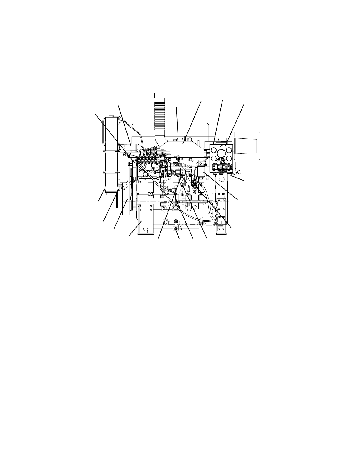
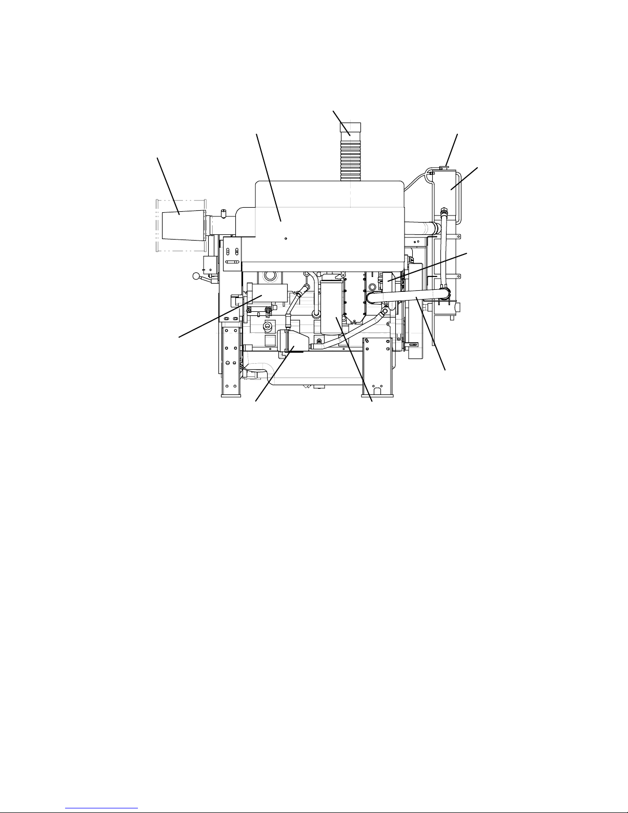
External Engine Components and Views
The following illustrations show the locations of the major external engine components, and other service and
maintenance points. Some external components will be at different locations for different engine models.
Instrument Panel Side
5
6
7
8
9
10
1. Instrument Panel 7. Raw Water Outlet 13. Dipstick
2. Terminal Box 8. Raw Water Inlet 14. Lubricating Oil Fill
3. Charge Air Cooler 9. Flywheel Housing 15. Lift Pump
4. Turbocharger 10. Engine Support 16. Fuel Filter
5. Upper Water Hose/Tube 11. Electric Fuel Solenoid 17. Manual Start
6. Fuel Pump 12. Oil Pan Drain
4
1
3
13 1
2
1
17
16
15
Drawing No. 9777, Section 2, Rev. 02-07
Section 2 - Engine Identification Page 2-5
CFP83 Series
Turbocharger Side
2
3
1
4
9
5
8
76
1. Top Tank Fill 6. Coolant Heater
2. Exhaust 7. Lubricating Oil Filter
3. Turbocharger and Exhaust Shield 8. Lower Water Hose/Tube
4. Air Cleaner Element 9. Alternator
5. Starter Motor 10. Heat Exchanger
10
Drawing No. 9777, Section 2, Rev. 02-07
Page 2-6 Section 2 – Engine Identification
CFP83 Series
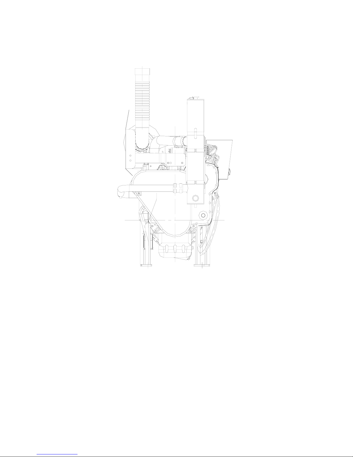
Front View
Drawing No. 9777, Section 2, Rev. 02-07
Section 2 - Engine Identification Page 2-7
CFP83 Series
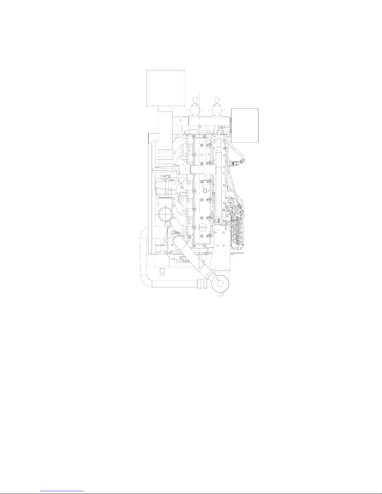
Top View
Drawing No. 9777, Section 2, Rev. 02-07
Page 2-8 Section 2 – Engine Identification
CFP83 Series
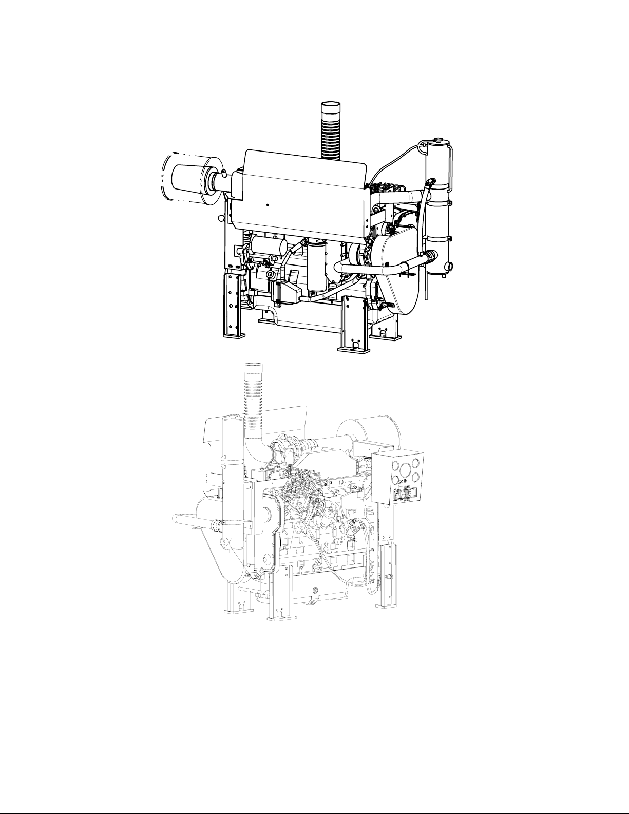
Isometric Views
Drawing No. 9777, Section 2, Rev. 02-07
Section 2 - Engine Identification Page 2-9
CFP83 Series
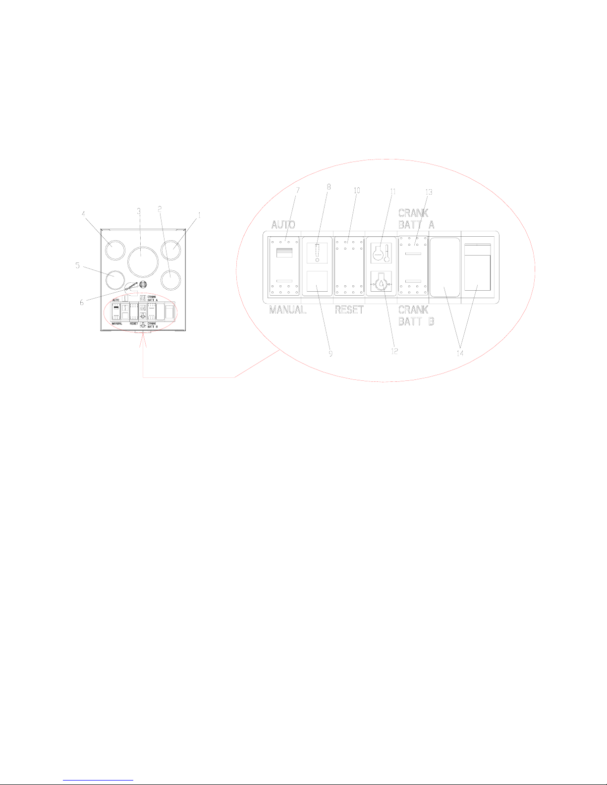
Instrument Panel
1. Battery “A” Voltmeter 8. Overspeed Warning Light
2. Battery “B” Voltmeter 9. Not used
3. Tachometer (with hour-meter) 10. Overspeed Reset Switch
4. Water Temperature Gauge 11. High Water Temperature Warning Light
5. Lubricating Oil Pressure Gauge 12. Low Oil Pressure Warning Light
6. Circuit Breaker 13. Battery A/B Switch
7. ON/OFF Switch (AUTO/MANUAL) 14. ECM Indicators (For Electronic Engine
Models)
Drawing No. 9777, Section 2, Rev. 02-07
Page 2-10 Section 2 – Engine Identification
CFP83 Series
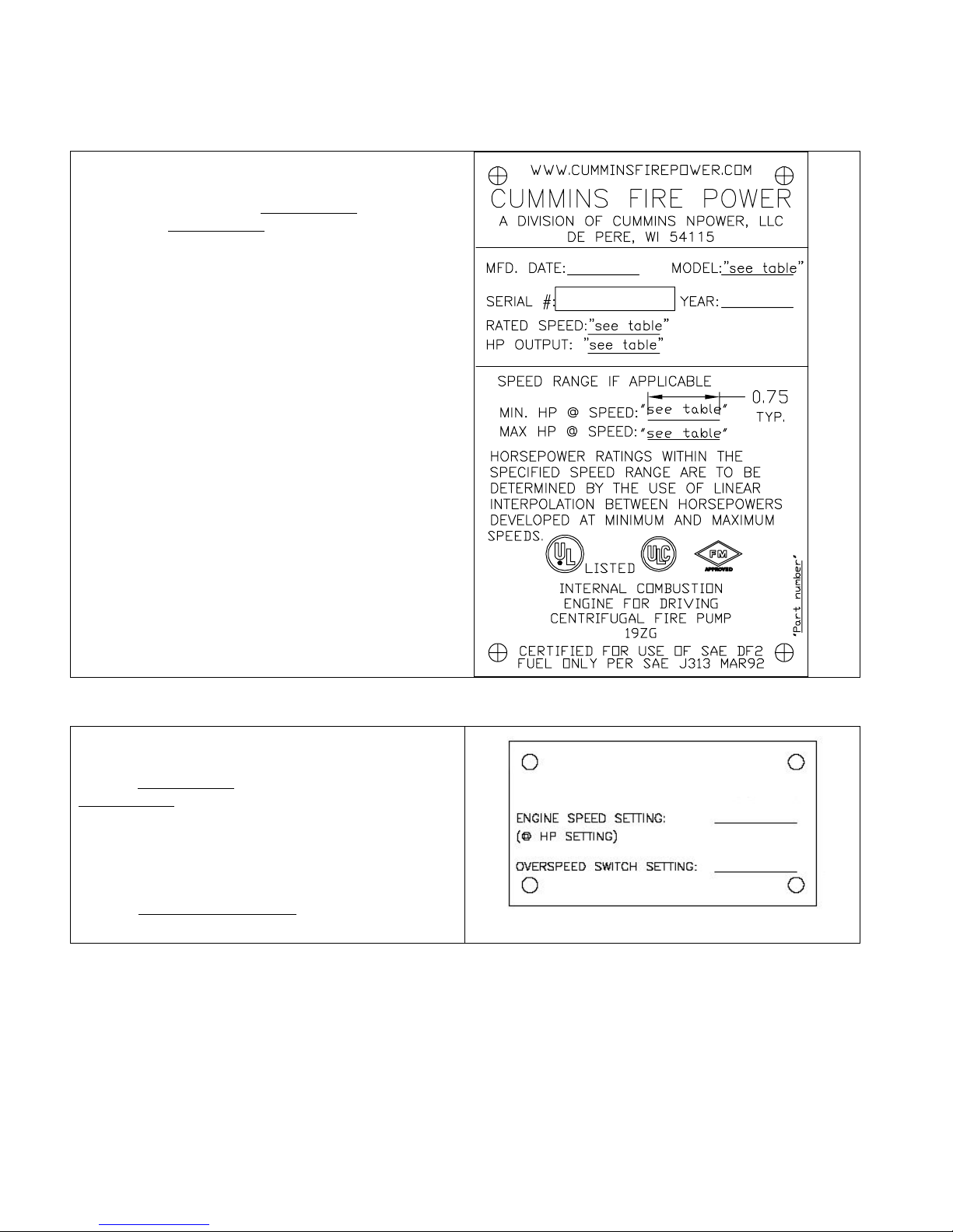
Fire Pump Engine Data Tag
The Fire Pump Engine Data Tag is located at the
pump end of the engine just above the redundant
starter solenoids. Refer to Drawing 8708
F20, F30) or Drawing 8710
for location details.
This tag shows specific information about your engine.
The engine serial number provides information for
ordering parts and service needs.
NOTE: The fire pump dataplate must not be changed
unless approved by Cummins Fire Power.
(CFP83-F40) in Section 13
(CFP83-F10,
Factory Setting Tag
The Factory Setting Tag is located at the pump end of
the engine just above the redundant starter solenoids.
Refer to Drawing 8708
Drawing 8710
details.
This tag identifies to rated operating speed at the rated
horsepower. It also provides the over speed switch
setpoint. Both values are set at the factory.
Refer to Installation Instructions
procedures to verify or adjust either setpoint.
(CFP83-F40) in Section 13 for location
(CFP83-F10, F20, F30) or
in Section 3 for
FACTORY SETTING
Drawing No. 9777, Section 2, Rev. 02-07
Section 2 - Engine Identification Page 2-11
CFP83 Series
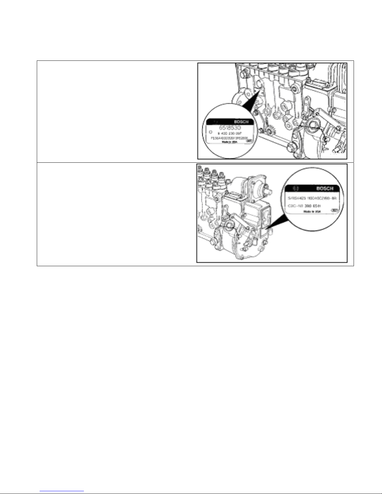
Fuel Injection Pump Dataplate
The Bosch® fuel injection pump dataplate is located
on the side of the injection pump. It provides
information for fuel pump calibration.
The Cummins part number for the fuel pumpgovernor combination is located on the governor
dataplate.
Drawing No. 9777, Section 2, Rev. 02-07

Page 2-12 Section 2 – Engine Identification
CFP83 Series
THIS PAGE INTENTIONALLY LEFT BLANK
Drawing No. 9777, Section 2, Rev. 02-07
 Loading...