

CUMMINS CFP83 SERIES, CFP83-F10, CFP83-F20, CFP83-F30, CFP83-F40 Operation & Maintenance Manual
Page 1
CFP83 SERIES
Operation & Maintenance Manual
Fire Pump Drive Engines
www.cumminsfirepower.com
Page 2

Page ii
Foreword
This manual contains information for the correct operation and maintenance of a Cummins Fire Pump engine.
It also includes important safety information, engine and systems specifications, troubleshooting guidelines, and
listings of Cummins Authorized Repair Locations.
Read and follow all safety instructions. Refer to the General Safety Instructions
Keep this manual with the equipment. If the equipment is traded or sold, give the manual to the new owner.
The information, specifications, and recommended maintenance guidelines in this manual are based on
information in effect at the time of printing. Cummins Fire Power, Cummins NPower and Cummins Engine
Company, Inc. reserve the right to make changes at any time without obligation. If any differences are found
between an engine and the information in this manual, contact the local Cummins Authorized Repair Location.
The latest technology and the highest quality components were used to produce this engine. When replacement
parts are needed, we recommend using only genuine Cummins or ReCon® exchange parts. These parts can be
identified by the following trademarks:
NOTE: Warranty information is located in Section 11. Make sure you are familiar with the warranty or warranties
applicable to your engine.
in Section 1.
© 2005 Cummins Inc., Box 3005, Columbus, IN 47202-3005 U.S.A.
Drawing No. 9777, Section 0, Rev. 02-07
Page 3

Page iii
Index of Sections
Introduction ………………………………………………………………….……………….......................................... 1
Engine Identification …………………………………………………………………………… ................................... 2
Installation and Operation ………………………………………………………….………….. .................................. 3
Maintenance Guidelines ……………………………………………………….…………...........................................4
Maintenance Procedures ……………………………………………………………..................................................5
System Diagrams …………………………………………………………………………... ......................................... 6
Adjustment, Replace and Replacement……………………………............................... ....................................... 7
Service Literature …………………………………………………………………………… ........................................ 8
Service Assistance ………..………………………………………………………………... ........................................ 9
Maintenance Specifications ……………………………………............................................................................ 10
Warranty Information…………………………………………………………………………………….. ....................11
Troubleshooting …………………………………………………………………………….. ......................................12
Assembly Drawings…………………………………………………………………………. ...................................... 13
Drawing No. 9777, Section 0, Rev. 02-07
Page 4

Page iv
THIS PAGE INTENTIONALLY LET BLANK
Drawing No. 9777, Section 0, Rev. 02-07
Page 5

Section 1 – Introduction Page 1-1
CFP83 Series
Section 1 – Introduction
Section Contents
Page
To the Owner and Operator .............................................................................................................1-3
About the Manual..............................................................................................................................1-3
How to Use the Manual ....................................................................................................................1-3
Symbols .............................................................................................................................................1-4
Illustrations .......................................................................................................................................1-5
General Safety Instructions.............................................................................................................1-6
General Cleaning Instructions ........................................................................................................1-8
Acronyms and Abbreviations..........................................................................................................1-14
Drawing No. 9777, Section 1, Rev. 02-07
Page 6

Page 1-2 Section 1 – Introduction
CFP83 Series
THIS PAGE INTENTIONALLY LEFT BLANK
Drawing No. 9777, Section 1, Rev. 02-07
Page 7

Section 1 – Introduction Page 1-3
CFP83 Series
To the Owner and Operator
Preventative maintenance is the easiest and least expensive type of maintenance. Follow the maintenance
schedule recommendations outlined in Maintenance Guidelines
Keep records of regularly scheduled maintenance.
in Section 4.
Use the correct fuel, oil, coolant, and filters in the engine as specified in Maintenance Specifications
10.
Cummins Fire Power, Cummins NPower and Cummins Engine Company, Inc use the latest technology and the
highest quality components to produce its engines. Cummins recommends using only genuine Cummins parts.
Personnel at Cummins Authorized Repair Locations have been trained to provide expert service and parts
support. If a problem that can not be resolved by a Cummins Authorized Repair Location occurs, follow the
steps outlined in the Service Assistance
in Section 9.
in Section
About the Manual
This manual contains information needed to operate and maintain an engine correctly as recommended by
Cummins Fire Power, Cummins NPower and Cummins Engine Company, Inc. Additional service literature
(troubleshooting and repair manual) can be ordered by filling out and mailing the Literature Order Form located
in Service Literature
Both metric and U.S. customary values are listed in this manual. The metric value is listed first, followed by the
U.S. customary in brackets.
Numerous illustrations and symbols are used to aid in understanding the meaning of the text. Refer to the
Symbols
Each section is preceded by a Section Contents to aid in locating information more quickly.
subsection in this section for a complete listing of symbols and their definitions.
in Section 8.
How to Use the Manual
This manual is organized according to intervals at which maintenance on the engine is to be performed. A table
that states the required intervals and the checks to be made is located in Section 4. Locate the interval at which
maintenance will be performed, then follow the steps given in the referenced section for all the procedures to be
performed. All the procedures done under previous maintenance intervals must be performed, also.
Keep a record of all the checks and inspections made. A record form for recording date, mileage/kilometer or
hours, and which maintenance checks were performed is located in Section 4.
Refer to the Maintenance Specifications
Company, Inc., for your engine. Specifications and torque values for each engine system are given in that
section.
Drawing No. 9777, Section 1, Rev. 02-07
in Section 10 for specifications recommended by Cummins Engine
Page 8
Page 1-4 Section 1 – Introduction
CFP83 Series
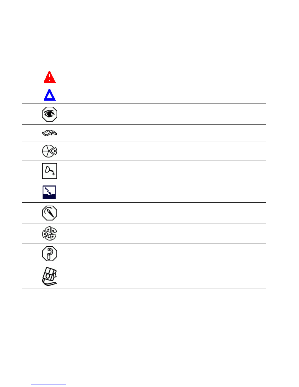
Symbols
The following symbols have been used in this manual to help communicate the intent of the instructions. When
one of the symbols appears, it conveys the meaning define below:
WARNING. Serious personal injury or extensive property damage can result if the
warning instructions are not followed.
CAUTION. Minor personal injury can result or a part, an assembly, or the engine can
be damaged if the caution instructions are not followed.
INSPECTION is required.
Refer to another location in this manual or another publication for additional
information.
Indicates a REMOVAL or DISASSEMBLY step
LUBRICATE the part or assembly.
CLEAN the part or assembly.
TIGHTEN to a specific torque.
Indicates an INSTALLATION or an ASSEMBLY step
PERFORM a mechanical or time MEASUREMENT.
PERFORM an electrical MEASUREMENT.
Drawing No. 9777, Section 1, Rev. 02-07
Page 9
Section 1 – Introduction Page 1-5
CFP83 Series
Illustrations
The illustrations used in this manual are
intended to give an example of a problem, and
to show what to look for and where the problem
can be found.
Some of the illustrations are “generic” and might
not look exactly like the engine or parts used in
your application.
The illustrations can contain symbols to indicate
an action required, and an acceptable or not
acceptable condition.
The illustrations are also intended to show
repair or replacement procedures.
The illustration can differ from your application,
but the procedure given will be the same.
Drawing No. 9777, Section 1, Rev. 02-07
Page 10

Page 1-6 Section 1 – Introduction
CFP83 Series
General Safety Instructions
WARNING
Improper practices or carelessness can cause burns, cuts, mutilation, asphyxiation or other bodily
injury or death.
• Read and understand all of the safety precautions and warnings before performing any repair. This list
contains the general safety precautions that must be followed to provide personal safety. Special safety
precautions are included in the procedures when they apply.
• Make sure the work area surrounding the product is dry, well lit, ventilated; free from clutter, loose tools,
parts, ignition sources and hazardous substances. Be aware of hazardous conditions that can exist.
• Always wear protective glasses and protective shoes when working.
• Rotating parts can cause cuts, mutilation or strangulation.
• Do not wear loose-fitting or torn clothing. Remove all jewelry when working.
• Disconnect the battery (negative [-] cable first) and discharge any capacitors before beginning any repair
work. Put a "Do Not Operate" tag on the controls.
• Use ONLY the proper engine barring techniques for manually rotating the engine. Do not attempt to rotate
the crankshaft by pulling or prying on the fan. This practice can cause serious personal injury, property
damage, or damage to the fan blade(s) causing premature fan failure.
• If an engine has been operating and the coolant is hot, allow the engine to cool before you slowly loosen the
filler cap and relieve the pressure from the cooling system.
• Do not work on anything that is supported ONLY by lifting jacks or a hoist. Always use blocks or proper
stands to support the product before performing any service work.
• Relieve all pressure in the air, oil, and the cooling systems before any lines, fittings, or related items are
removed or disconnected. Be alert for possible pressure when disconnecting any device from a system that
utilizes pressure. Do not check for pressure leaks with your hand. High pressure oil or fuel can cause
personal injury.
• To avoid personal injury, use a hoist or get assistance when lifting components that weigh 23 kg [50 lb] or
more. Make sure all lifting devices such as chains, hooks, or slings are in good condition and are of the
correct capacity. Make sure hooks are positioned correctly. Always use a spreader bar when necessary.
The lifting hooks must not be side-loaded.
• Corrosion inhibitor contains alkali. Do not get the substance in your eyes. Avoid prolonged or repeated
contact with skin. Do not swallow internally. In case of contact, immediately wash skin with soap and water.
In case of contact, immediately flood eyes with large amounts of water for a minimum of 15 minutes.
IMMEDIATELY CALL A PHYSICIAN. KEEP OUT OF REACH OF CHILDREN.
Drawing No. 9777, Section 1, Rev. 02-07
Page 11

Section 1 – Introduction Page 1-7
CFP83 Series
General Safety Instructions (Cont.)
• Naphtha and Methyl Ethyl Ketone (MEK) are flammable materials and must be used with caution. Follow the
manufacturer's instructions to provide complete safety when using these materials. KEEP OUT OF REACH
OF CHILDREN.
• To avoid burns, be alert for hot parts on products that have just been turned OFF, and hot fluids in lines,
tubes, and compartments.
• Always use tools that are in good condition. Make sure you understand how to use them before performing
any service work. Use ONLY genuine Cummins or Cummins ReCon® replacement parts.
• Always use the same fastener part number (or equivalent) when replacing fasteners. Do not use a fastener
of lesser quality if replacements are necessary.
• Do not perform any repair when fatigued or after consuming alcohol or drugs that can impair your
functioning.
• Some state and federal agencies in the United States of America have determined that used engine oil can
be carcinogenic and can cause reproductive toxicity. Avoid inhalation of vapors, ingestion, and prolonged
contact with used engine oil. Dispose of waste oil in accordance with applicable requirements.
Drawing No. 9777, Section 1, Rev. 02-07
Page 12

Page 1-8 Section 1 – Introduction
CFP83 Series
General Cleaning Instructions
WARNING
Abrasive material must be kept out of or removed from oil passages and parts wear points. Abrasive
material in oil passages can cause bearing and bushing failures that can progress to major component
damage beyond reuse. This is particularly true of main and rod bearings.
WARNING
Excessive sanding or grinding the carbon ring from the top of the cylinder liners can damage the liner
beyond reuse. The surface finish will be damaged and abrasive particles can be forced into the liner
material which can cause early cylinder wear-out or piston ring failures.
WARNING
When using solvents, acids, or alkaline materials for cleaning, follow the manufacturer’s
recommendations for use. Wear goggles and protective clothing to reduce the possibility of personal
injury.
WARNING
When using a steam cleaner, wear safety glasses or a face shield, as well as protective clothing. Hot
steam can cause serious personal injury.
CAUTION
Do not use bead blasting cleaning methods on aluminum pistons skirts or the pin bores in any piston,
piston skirt or piston crown. Small particles of the media will embed in the aluminum or other soft metal
and result in premature wear of the cylinder liner, piston rings, pins and pin bores. Valves, turbocharger
shafts, etc., can also be damaged. Follow the cleaning directions listed in the procedures.
CAUTION
Do not contaminate wash tanks and tank type solvent cleaners with the foreign material and plastic
beads. Remove the foreign material and plastic beads with compressed air, hot high pressure water or
steam before placing them in tanks or cleaners. The foreign material and plastic beads can contaminate
the tank and any other engine parts cleaned in the tank. Contaminated parts may cause failures from
abrasive wear.
CAUTION
The bead blasting operation must not disturb the metal surface. If the metal surface is disturbed the
engine can be damaged due to increased parts clearance or inadequate surface finish on parts that
move against other parts.
Drawing No. 9777, Section 1, Rev. 02-07
Page 13

Section 1 – Introduction Page 1-9
CFP83 Series
Definition of Clean
Parts must be free of debris that can contaminate any engine system. This does not necessarily mean they
have to appear as new.
Sanding gasket surfaces until the factory machining marks are disturbed adds no value and is often harmful to
forming a seal. It is important to maintain surface finish and flatness tolerances to form a quality sealing surface.
Gaskets are designed to fill small voids in the specified surface finish.
Sanding gasket surfaces where edge-molded gaskets are used is most often unnecessary. Edge-molded
gaskets are those metal carriers with sealing material bonded to the edges of the gasket to seal while the metal
portion forms a metal to metal joint for stability. Any of the small amounts of sealing material that can stick to the
parts are better removed with a blunt-edged scraper on the spots rather than spending time polishing the whole
surface with an air sander or disc.
For those gaskets that do not have the edge molding, nearly all have a material that contains release agents to
prevent sticking. Certainly this is not to say that some gaskets are not difficult to remove because the gasket has
been in place a long time, has been overheated or the purpose of the release agent has been defeated by the
application of some sealant. The object however is just to remove the gasket without damaging the surfaces of
the mating parts without contaminating the engine (don't let the little bits fall where they can not be removed).
Bead blasting piston crowns until the dark stain is removed is unnecessary. All that is required is to remove the
carbon build-up above the top ring and in the ring grooves. There is more information on bead blasting and
piston cleaning later in this document.
Cummins Inc. does not recommend sanding or grinding the carbon ring at the top of cylinder liners until clean
metal is visible. The liner will be ruined and any signs of a problem at the top ring reversal point (like a dust-out)
will be destroyed. It is necessary to remove the carbon ring to provide for easier removal of the piston assembly.
A medium bristle, high quality, steel wire wheel that is rated above the rpm of the power tool being used will be
just as quick and there will be less damage. Yes, one must look carefully for broken wires after the piston is
removed but the wires are more visible and can be attracted by a magnet.
Oil on parts that have been removed from the engine will attract dirt in the air. The dirt will adhere to the oil. If
possible, leave the old oil on the part until it is ready to be cleaned, inspected and installed, and then clean it off
along with any attracted dirt. If the part is cleaned then left exposed it can have to be cleaned again before
installation. Make sure parts are lubricated with clean oil before installation. They do not need to be oiled all over
but do need oil between moving parts (or a good lube system priming process conducted before cranking the
engine).
Bead blasting parts to remove exterior paint is also usually unnecessary. The part will most likely be painted
again so all that needs happen is remove any loose paint.
Drawing No. 9777, Section 1, Rev. 02-07
Page 14

Page 1-10 Section 1 – Introduction
CFP83 Series
Using Abrasive Pads and Abrasive Paper
The keyword here is "abrasive". There is no part of an engine designed to withstand abrasion. That is they are
all supposed to lock together or slide across each other. Abrasives and dirt particles will degrade both functions.
WARNING
Abrasive material must be kept out of or removed from oil passages and parts wear points. Abrasive
material in oil passages can cause bearing and bushing failures that can progress to major component
damage beyond reuse. This is particularly true of main and rod bearings.
Cummins Inc. does not recommend the use of emery cloth or sand paper on any part of an assembled engine
or component including but not limited to removing the carbon ridge from cylinder liners or to clean block decks
or counterbores.
Great care must be taken when using abrasive products to clean engine parts, particularly on partially
assembled engines. Abrasive cleaning products come in many forms and sizes. All of them contain aluminum
oxide particles, silicon carbide, or sand or some other similar hard material. These particles are harder than
most of the parts in the engine. Since they are harder, if they are pressed against softer material they will either
damage the material or become embedded in it. These materials fall off the holding media as the product is
used. If the products are used with power equipment the particles are thrown about the engine. If the particles
fall between two moving parts, damage to the moving parts is likely.
If particles that are smaller than the clearance between the parts while they are at rest (engine stopped), but
larger than the running clearance then damage will occur when the parts move relative to each other (engine
started). While the engine is running and there is oil pressure, particles that are smaller than the bearing
clearance are likely to pass between the parts without damage and be trapped in the oil filter. However, particles
larger than the bearing clearance will remove material from one part and can become embedded in one of the
parts. Once embedded in one part it will abrade the other part until contact is no longer being made between the
two parts. If the damage sufficiently degrades the oil film, the two parts will come into contact resulting in early
wear-out or failure from lack of effective lubrication.
Abrasive particles can fly about during cleaning it is very important to block these particles from entering the
engine as much as possible. This is particularly true of lubricating oil ports and oil drilling holes, especially those
located downstream of the lubricating oil filters. Plug the holes instead of trying to blow the abrasive particles
and debris with compressed air because the debris is often simply blown further into the oil drilling.
All old gasket material must be removed from the parts gasket surfaces. However, it is not necessary to clean
and polish the gasket surface until the machining marks are erased. Excessive sanding or buffing can damage
the gasket surface. Many newer gaskets are of the edge molded type (a steel carrier with a sealing member
bonded to the steel). What little sealing material that can adhere is best removed with a blunt-edged scraper or
putty knife. Cleaning gasket surfaces where an edge-molded gasket is used with abrasive pads or paper is
usually a waste of time.
WARNING
Excessive sanding or grinding the carbon ring from the top of the cylinder liners can damage the liner
beyond reuse. The surface finish will be damaged and abrasive particles can be forced into the liner
material which can cause early cylinder wear-out or piston ring failures.
Tape off or plug all openings to any component interior before using abrasive pads or wire brushes. If really
necessary because of time to use a power tool with abrasive pads, tape the oil drillings closed or use plug and
clean as much of the surface as possible with the tool but clean around the oil hole/opening by hand so as to
prevent contamination of the drilling. Then remove the tape or plug and clean the remaining area carefully and
without the tool. DO NOT use compressed air to blow the debris out of oil drilling on an assembled engine! More
likely than not, the debris can be blown further into the drilling. Using compressed air is fine if both ends of the
drilling are open but that is rarely the case when dealing with an assembled engine.
Drawing No. 9777, Section 1, Rev. 02-07
Page 15

Section 1 – Introduction Page 1-11
CFP83 Series
Cleaning Gasket Surfaces
The object of cleaning gasket surfaces is to remove any gasket material, not refinish the gasket surface of the
part.
Cummins Inc. does not recommend any specific brand of liquid gasket remover. If a liquid gasket remover is
used, check the directions to make sure the material being cleaned will not be harmed.
Air powered gasket scrapers can save time but care must be taken to not damage the surface. The angled part
of the scraper must be against the gasket surface to prevent the blade from digging into the surface. Using air
powered gasket scrapers on parts made of soft materials takes skill and care to prevent damage.
Do not scrape or brush across the gasket surface if at all possible.
Solvent and Acid Cleaning
Several solvent and acid-type cleaners can be used to clean the disassembled engine parts (other than pistons.
See Below). Experience has shown that the best results can be obtained using a cleaner that can be heated to
90 to 95 °C (180 to 200 °F). Kerosene emulsion based cleaners have different temperature specifications, see
below. A cleaning tank that provides a constant mixing and filtering of the cleaning solution will give the best
results. Cummins Inc. does not recommend any specific cleaners. Always follow the cleaner manufacturer's
instructions. Remove all the gasket material, o-rings, and the deposits of sludge, carbon, etc., with a wire brush
or scraper before putting the parts in a cleaning tank. Be careful not to damage any gasket surfaces. When
possible, steam clean the parts before putting them in the cleaning tank.
WARNING
When using solvents, acids, or alkaline materials for cleaning, follow the manufacturer’s
recommendations for use. Wear goggles and protective clothing to reduce the possibility of personal
injury.
Experience has shown that kerosene emulsion based cleaners perform the best to clean pistons. These
cleaners should not be heated to temperature in excess of 77 °C (170 °F). The solution begins to break down at
temperatures in excess of 82 °C (180 °F) and will be less effective.
Do not use solutions composed mainly of chlorinated hydrocarbons with cresols, phenols and/or cresylic
components. They often do not do a good job of removing deposits from the ring groove and are costly to
dispose of properly.
Solutions with a pH above approximately 9.5 will cause aluminum to turn black; therefore do not use high
alkaline solutions.
Chemicals with a pH above 7.0 are considered alkaline and those below 7.0 are acidic. As you move further
away from the neutral 7.0, the chemicals become highly alkaline or highly acidic.
Remove all the gasket material, o-rings, and the deposits of sludge, carbon, etc., with a wire brush or scraper
before putting the parts in a cleaning tank. Be careful to not damage any gasket surfaces. When possible use
hot high pressure water or steam clean the parts before putting them in the cleaning tank. Removing the
heaviest dirt before placing in the tank will allow the cleaner to work more effectively and the cleaning agent will
last longer.
Rinse all the parts in hot water after cleaning. Dry completely with compressed air. Blow the rinse water from all
the capscrew holes and the oil drillings.
If the parts are not to be used immediately after cleaning, dip them in a suitable rust proofing compound. The
rust proofing compound must be removed from the parts before assembly or installation on the engine.
Drawing No. 9777, Section 1, Rev. 02-07
Page 16

Page 1-12 Section 1 – Introduction
CFP83 Series
Steam Cleaning
Steam cleaning can be used to remove all types of dirt that can contaminate the cleaning tank. It is a good
method for cleaning the oil drillings and coolant passages.
WARNING
When using a steam cleaner, wear safety glasses or a face shield, as well as protective clothing. Hot
steam can cause serious personal injury.
Do not steam clean the following components:
• Electrical Components
• Wiring Harnesses
• Injectors
• Fuel Pump
• Belts and Hoses
• Bearings (ball or taper roller)
• Electronic Control Module (ECM)
• ECM Connectors
Plastic Bead Cleaning
Cummins Inc. does not recommend the use of glass bead blast or walnut shell media on any engine part.
Cummins Inc. recommends using only plastic bead media, Part Number 3822735 or equivalent on any engine
part. Never use sand as a blast media to clean engine parts. Glass and walnut shell media when not used to the
media manufacturer's recommendations can cause excess dust and can embed in engine parts that can result
in premature failure of components through abrasive wear.
Plastic bead cleaning can be used on many engine components to remove carbon deposits. The cleaning
process is controlled by the use of plastic beads, the operating pressure and cleaning time.
CAUTION
Do not use bead blasting cleaning methods on aluminum pistons skirts or the pin bores in any piston,
piston skirt or piston crown. Small particles of the media will embed in the aluminum or other soft metal
and result in premature wear of the cylinder liner, piston rings, pins and pin bores. Valves, turbocharger
shafts, etc., can also be damaged. Follow the cleaning directions listed in the procedures.
CAUTION
Do not contaminate wash tanks and tank type solvent cleaners with the foreign material and plastic
beads. Remove the foreign material and plastic beads with compressed air, hot high pressure water or
steam before placing them in tanks or cleaners. The foreign material and plastic beads can contaminate
the tank and any other engine parts cleaned in the tank. Contaminated parts may cause failures from
abrasive wear.
Plastic bead blasting media, Part Number 3822735, can be used to clean all piston ring grooves. Do not sure
any bead blasting media on piston pin bores or aluminum skirts.
Drawing No. 9777, Section 1, Rev. 02-07
Page 17

Section 1 – Introduction Page 1-13
CFP83 Series
Plastic Bead Cleaning (Cont)
Follow the equipment manufacturer's cleaning instructions. Make sure to adjust the air pressure in the blasting
machine to the bead manufacturer's recommendations. Turning up the pressure can move material on the part
and cause the plastic bead media to wear out more quickly. The following guidelines can be used to adapt to
manufacturer's instructions:
Bead size: U.S. size Number 16 — 20 for piston cleaning with plastic bead media, Part Number 3822735
Operating Pressure — 270 kPa (40 psi) for piston cleaning. Pressure should not cause beads to break.
Steam clean or wash the parts with solvent to remove all of the foreign material and plastic beads after cleaning.
Rinse with hot water. Dry with compressed air.
CAUTION
The bead blasting operation must not disturb the metal surface. If the metal surface is disturbed the
engine can be damaged due to increased parts clearance or inadequate surface finish on parts that
move against other parts.
When cleaning pistons, it is not necessary to remove all the dark stain from the piston. All that is necessary is to
remove the carbon on the rim and in the ring grooves. This is best done by directing the blast across the part as
opposed to straight at the part. If the machining marks are disturbed by the blasting process, then the pressure
is too high or the blast is being held on one spot too long. The blast operation must not disturb the metal
surface.
Walnut shell bead blast material is sometimes used to clean ferrous metals (iron and steel). Walnut shell
blasting produces a great amount of dust particularly when the pressure if the air pressure on the blasting
machine is increased above media manufacturer's recommendation. Cummins Inc. recommends not using
walnut shell media to clean engine parts due to the risk media embedment and subsequent contamination of the
engine.
Cummins Inc. now recommends glass bead media NOT used to clean any engine parts. Glass media is too
easily embedded into the material particularly in soft materials and when air pressures greater than media
manufacturer's recommend are used. The glass is an abrasive so when it is in a moving part, that part is
abrading all the parts in contact with it. When higher pressures are used the media is broken and forms a dust of
a very small size that floats easily in the air. This dust is very hard to control in the shop, particularly if only
compressed air (and not hot water) is used to blow the media after it is removed from the blasting cabinet
(blowing the part off inside the cabinet may remove large accumulations but never removes all the media).
Bead blasting is best used on stubborn dirt/carbon build-up that has not been removed by first steam/higher
pressure washing then washing in a heated wash tank. This is particularly true of pistons. Steam and soak the
pistons first then use the plastic bead method to safely remove the carbon remaining in the grooves (instead of
running the risk of damaging the surface finish of the groove with a wire wheel or end of a broken piston ring.
Make sure the parts are dry and oil free before bead blasting to prevent clogging the return on the blasting
machine.
Always direct the bead blaster nozzle "across" rather than directly at the part. This allows the bead to get under
the unwanted material. Keep the nozzle moving rather than hold on one place. Keeping the nozzle directed at
one-place too long causes the metal to heat up and be moved around. Remember that the spray is not just
hitting the dirt or carbon. If the machining marks on the piston groove or rim have been disturbed then there has
not been enough movement of the nozzle and/or the air pressure is too high.
Never bead blast valve stems. Tape or use a sleeve to protect the stems during bead blasting. Direct the nozzle
across the seat surface and radius rather than straight at them. The object is to remove any carbon build up and
continuing to blast to remove the stain is a waste of time.
Drawing No. 9777, Section 1, Rev. 02-07
Page 18

Page 1-14 Section 1 – Introduction
CFP83 Series
Acronyms and Abbreviations
AFC Air Fuel Control in. Inch
Amp Ampere in-lb Inch Pound
API American Petroleum Institute kg Kilograms
ASA Air Signal Attenuator kPa Kilopascal
ASTM American Society of Testing and Materials l Liter
AWG American Wire Gauge lb. pound
C Celsius lbf. Pound force
C.I.D. Cubic Inch Displacement m Meter
CAC Charge Air Cooler ml Milliliter
CARB California Air Resources Board mm Millimeter
cc Cubic Centimeter MPa Megapascal
cm Centimeter MPH Miles Per Hour
CPL Control Parts List MPQ Miles Per Quart
cSt Centistokes N Newton
D. Diameter N•m Newton-meter
DCA Diesel Coolant Additive OEM Original Equipment Manufacturer
E.C.S. Emission Control System oz. Ounce
ECM Electronic Control Module ppm Parts Per Million
EPA Environmental Protection Agency psi Pounds Per Square Inch
EPS Engine Position Sensor PTO Power Takeoff
F Fahrenheit qt Quart
FSO Fuel Shut-Off RPM Revolutions Per Minute
FSOS Fuel Shut-Off Switch S.A.E. Society of Automotive Engineers
ft-lb Foot-Pound STC Step Timing Control
GAL Gallon (US) TDC Top Dead Center
H2O Water US United States of America
Hg Mercury V Volt
HP Horsepower VS Variable Speed
Drawing No. 9777, Section 1, Rev. 02-07
Page 19

Section 2 – Engine Identification Page 2-1
CFP83 Series
Section 2 - Engine Identification
Section Contents
Page
Fire Pump Engines .............................................................................................................................................2-3
Overspeed Switches...........................................................................................................................................2-3
Operating Speed .................................................................................................................................................2-3
Control System ...................................................................................................................................................2-3
External Engine Components and Views.........................................................................................................2-4
Instrument Panel.................................................................................................................................................2-9
Fire Pump Engine Data Tag.............................................................................................................................2-10
Factory Setting Tag ..........................................................................................................................................2-10
Fuel Injection Pump Dataplate ........................................................................................................................2-11
Drawing No. 9777, Section 2, Rev. 02-07
Page 20

Page 2-2 Section 2 – Engine Identification
CFP83 Series
THIS PAGE INTENTIONALLY LEFT BLANK
Drawing No. 9777, Section 2, Rev. 02-07
Page 21

Section 2 - Engine Identification Page 2-3
CFP83 Series
Fire Pump Engines
Cummins’ complete line of fire pump engines have been approved as packaged units (engine and all
accessories) by Factory Mutual Research and listed by Underwriter’s Laboratories, Inc. and Underwriter’s
Laboratories of Canada. Because of the lengthy and expensive process to design and produce a fire pump
engine that meets these requirements, no deviations are permitted without approval. These engines are to be
used only for fire protection applications.
Overspeed Switches
Each engine is equipped with an overspeed switch which will activate the fuel pump solenoid valve and shut off
the engine when the RPM exceeds a present limit. The overspeed switch senses engine speed during the start
cycle and stops the starting motor cranking cycle. The overspeed switch must be adjusted to the required speed
limit during the in-service inspection.
Operating Speed
All Cummins fire pump engines are shipped from the factory with the operating speed adjusted to the lowest
approved operating speed. Final operating speed adjustment must be made at the time of the in-service
inspection to obtain the required fire pump operating speed specified by the pump manufacturer.
Control System
The function of a fire pump controller is to start the engine. These controllers are more sophisticated than
standard industrial controllers because they include special items for fire pumps. Several options are available:
The automatic start controller can be used for either automatic or manual stop after the fire demand signal is
removed.
Pressure recorders are available to provide a permanent record of water pressure fluctuations and engine
starts.
Sequential starting is available for multiple-pump installations to keep all pumps from starting simultaneously.
NOTE: Fire pump controllers are not supplied by Cummins Fire Power, or Cummins Engine Company, Inc.
Drawing No. 9777, Section 2, Rev. 02-07
Page 22
Page 2-4 Section 2 – Engine Identification
211
4
CFP83 Series
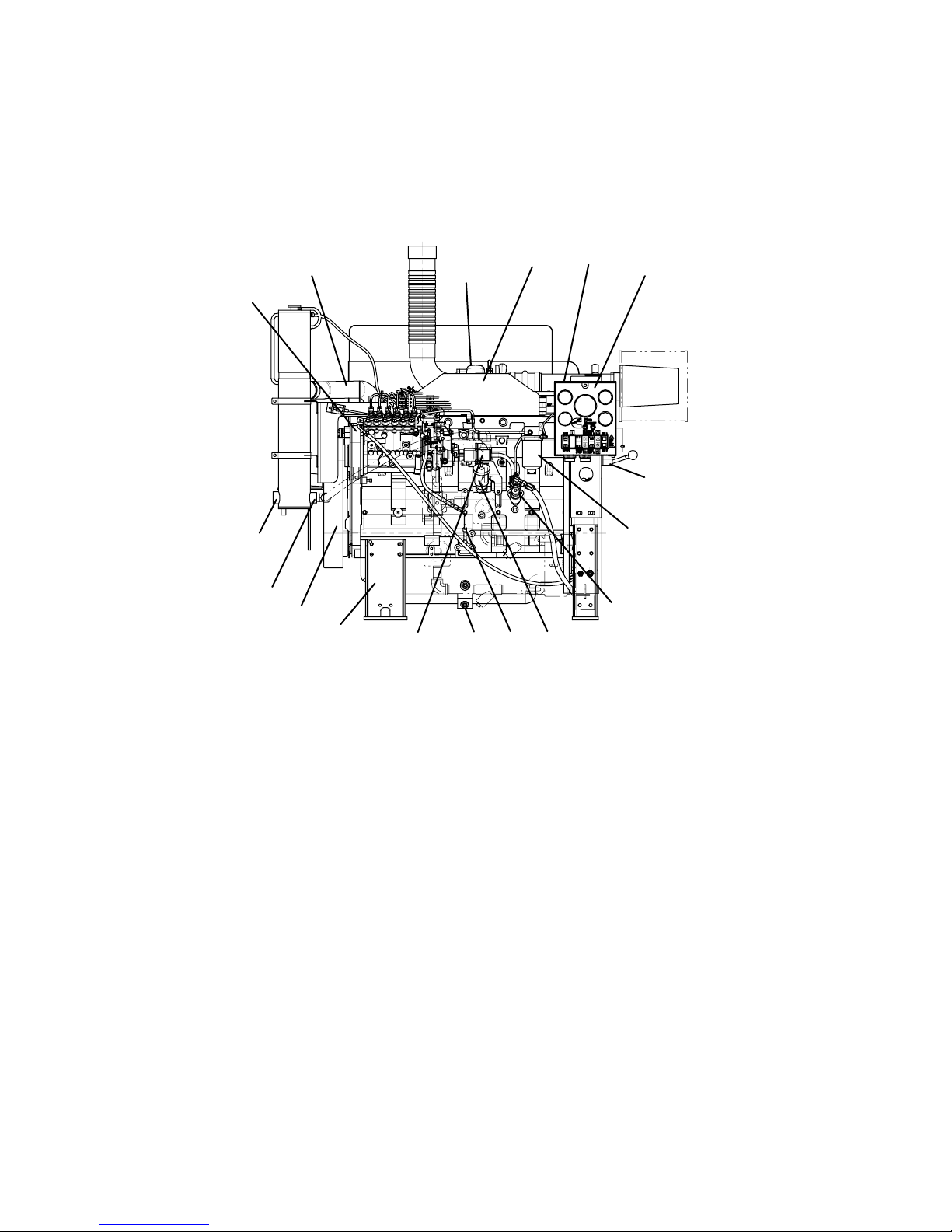
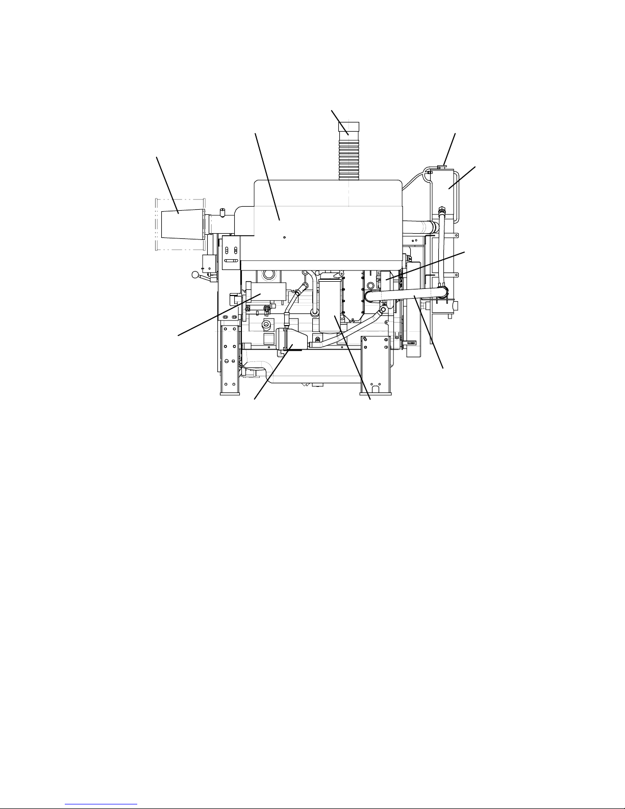
External Engine Components and Views
The following illustrations show the locations of the major external engine components, and other service and
maintenance points. Some external components will be at different locations for different engine models.
Instrument Panel Side
5
6
7
8
9
10
1. Instrument Panel 7. Raw Water Outlet 13. Dipstick
2. Terminal Box 8. Raw Water Inlet 14. Lubricating Oil Fill
3. Charge Air Cooler 9. Flywheel Housing 15. Lift Pump
4. Turbocharger 10. Engine Support 16. Fuel Filter
5. Upper Water Hose/Tube 11. Electric Fuel Solenoid 17. Manual Start
6. Fuel Pump 12. Oil Pan Drain
4
1
3
13 1
2
1
17
16
15
Drawing No. 9777, Section 2, Rev. 02-07
Page 23
Section 2 - Engine Identification Page 2-5
CFP83 Series
Turbocharger Side
2
3
1
4
9
5
8
76
1. Top Tank Fill 6. Coolant Heater
2. Exhaust 7. Lubricating Oil Filter
3. Turbocharger and Exhaust Shield 8. Lower Water Hose/Tube
4. Air Cleaner Element 9. Alternator
5. Starter Motor 10. Heat Exchanger
10
Drawing No. 9777, Section 2, Rev. 02-07
Page 24
Page 2-6 Section 2 – Engine Identification
CFP83 Series
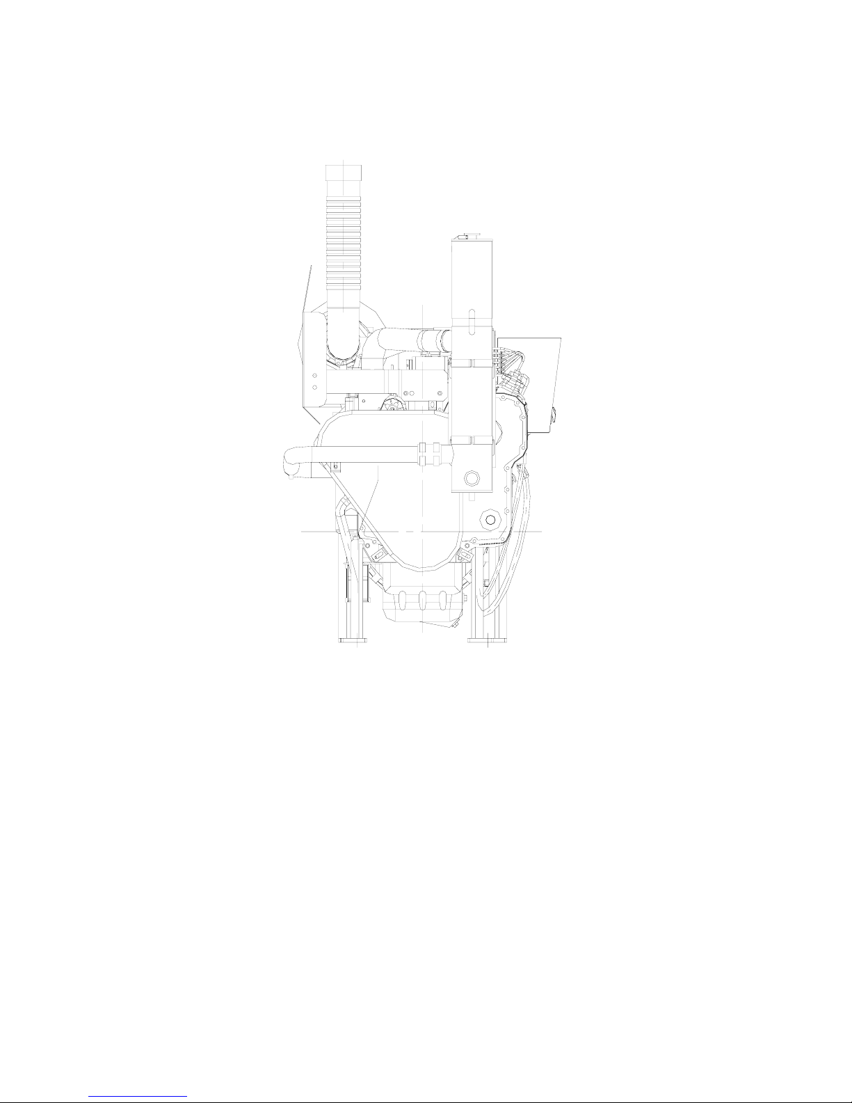
Front View
Drawing No. 9777, Section 2, Rev. 02-07
Page 25
Section 2 - Engine Identification Page 2-7
CFP83 Series
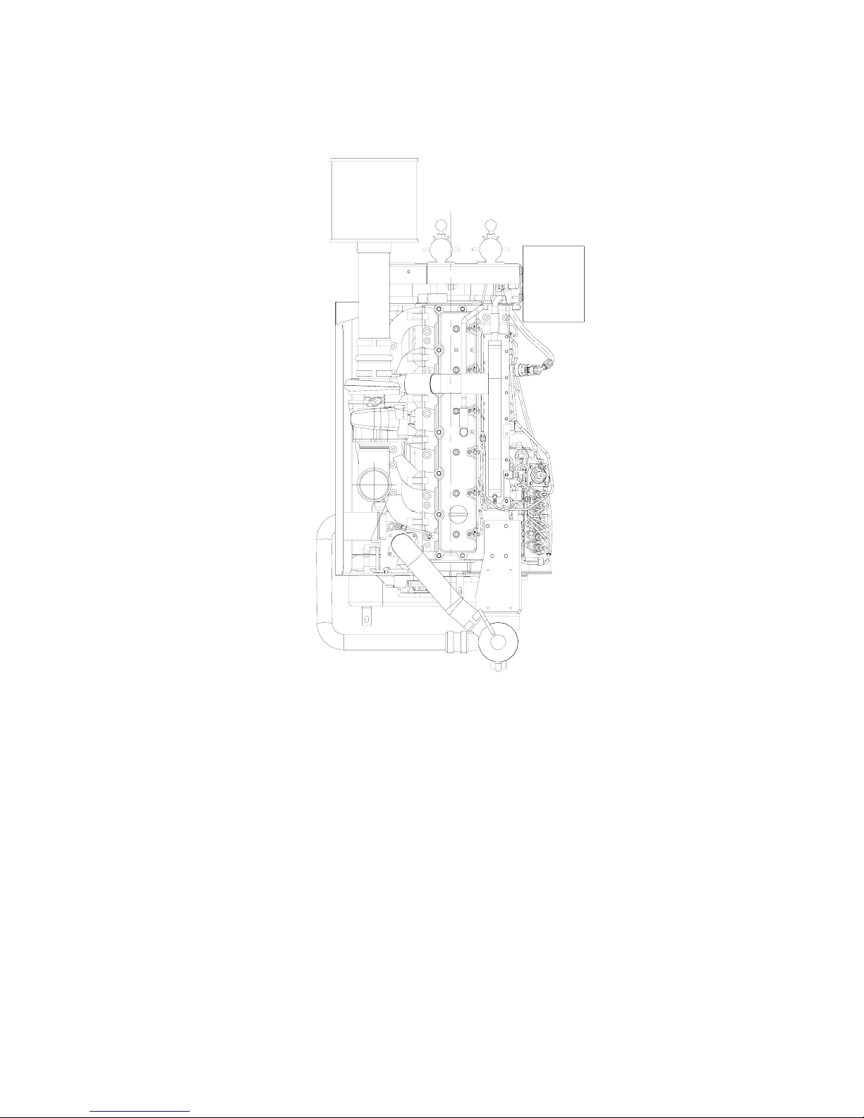
Top View
Drawing No. 9777, Section 2, Rev. 02-07
Page 26
Page 2-8 Section 2 – Engine Identification
CFP83 Series
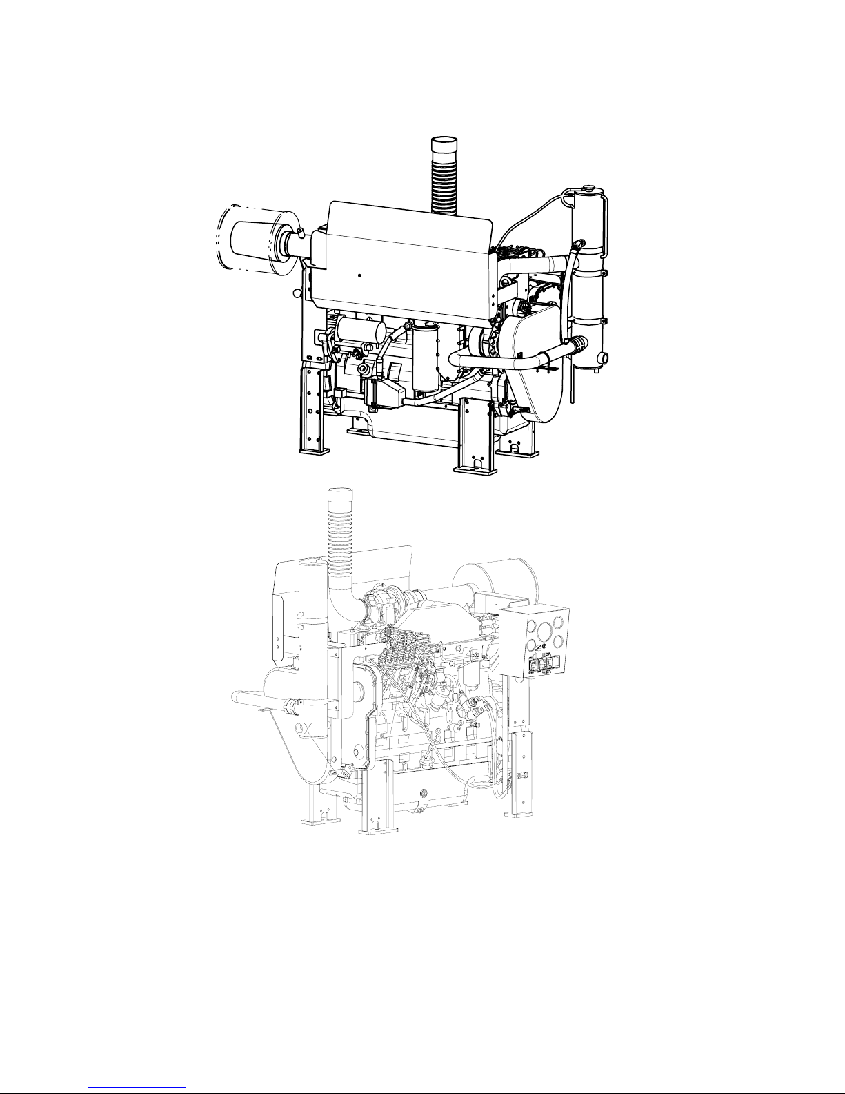
Isometric Views
Drawing No. 9777, Section 2, Rev. 02-07
Page 27
Section 2 - Engine Identification Page 2-9
CFP83 Series
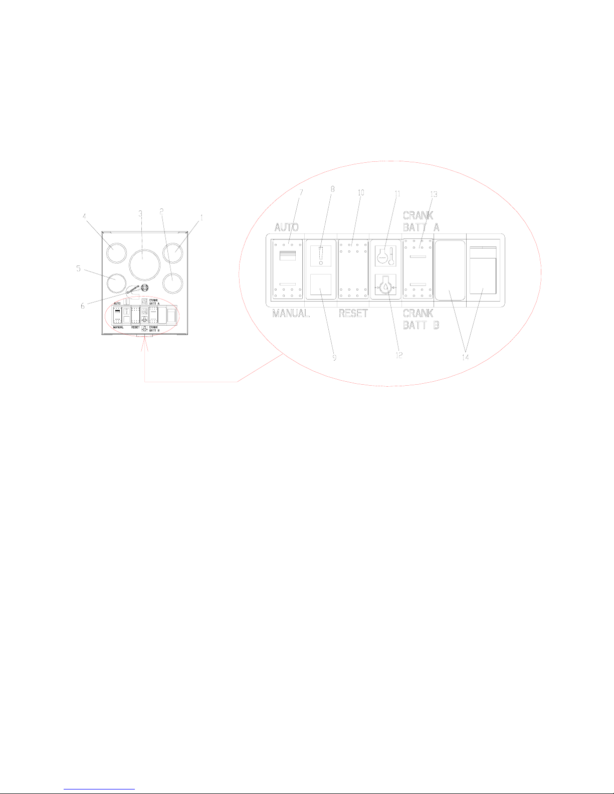
Instrument Panel
1. Battery “A” Voltmeter 8. Overspeed Warning Light
2. Battery “B” Voltmeter 9. Not used
3. Tachometer (with hour-meter) 10. Overspeed Reset Switch
4. Water Temperature Gauge 11. High Water Temperature Warning Light
5. Lubricating Oil Pressure Gauge 12. Low Oil Pressure Warning Light
6. Circuit Breaker 13. Battery A/B Switch
7. ON/OFF Switch (AUTO/MANUAL) 14. ECM Indicators (For Electronic Engine
Models)
Drawing No. 9777, Section 2, Rev. 02-07
Page 28
Page 2-10 Section 2 – Engine Identification
CFP83 Series
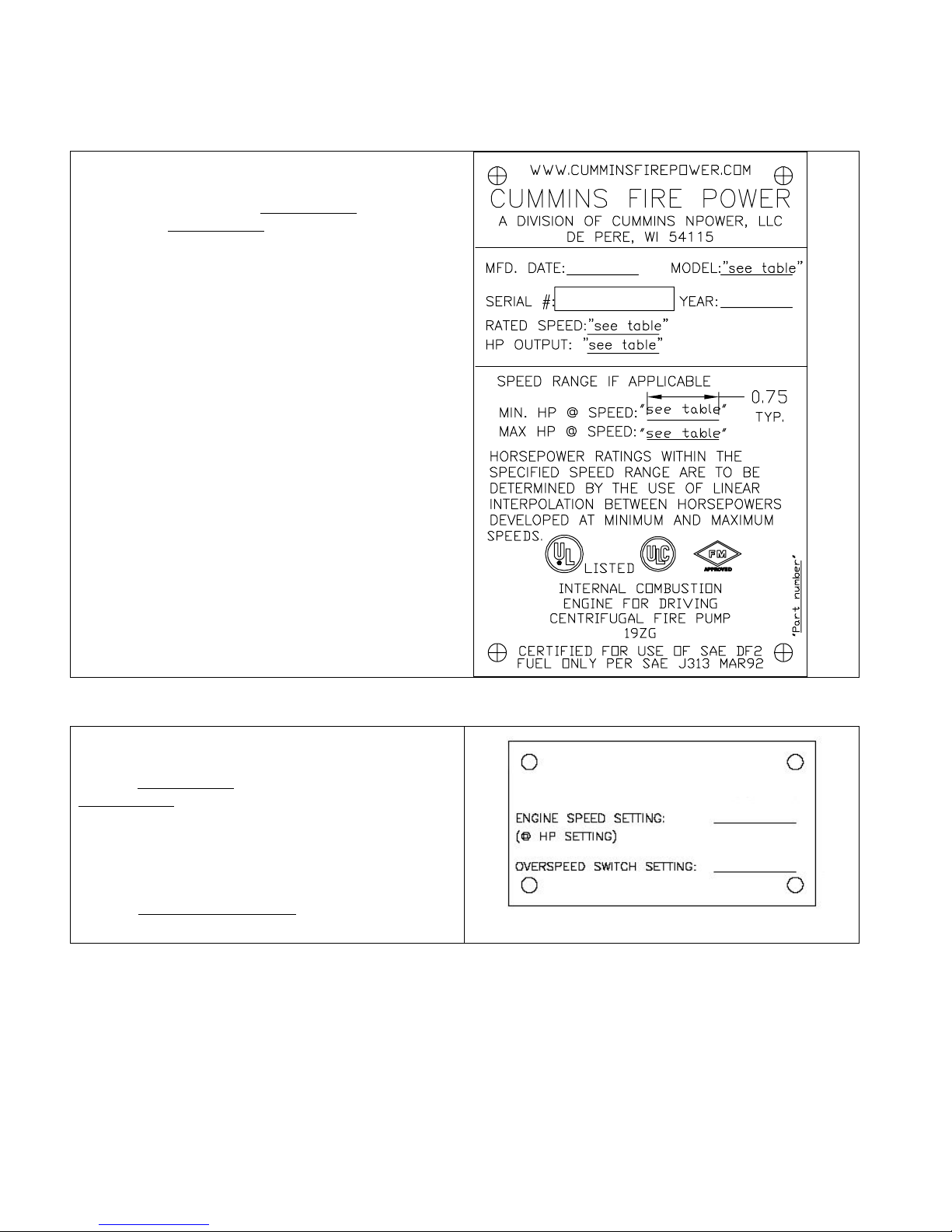
Fire Pump Engine Data Tag
The Fire Pump Engine Data Tag is located at the
pump end of the engine just above the redundant
starter solenoids. Refer to Drawing 8708
F20, F30) or Drawing 8710
for location details.
This tag shows specific information about your engine.
The engine serial number provides information for
ordering parts and service needs.
NOTE: The fire pump dataplate must not be changed
unless approved by Cummins Fire Power.
(CFP83-F40) in Section 13
(CFP83-F10,
Factory Setting Tag
The Factory Setting Tag is located at the pump end of
the engine just above the redundant starter solenoids.
Refer to Drawing 8708
Drawing 8710
details.
This tag identifies to rated operating speed at the rated
horsepower. It also provides the over speed switch
setpoint. Both values are set at the factory.
Refer to Installation Instructions
procedures to verify or adjust either setpoint.
(CFP83-F40) in Section 13 for location
(CFP83-F10, F20, F30) or
in Section 3 for
FACTORY SETTING
Drawing No. 9777, Section 2, Rev. 02-07
Page 29
Section 2 - Engine Identification Page 2-11
CFP83 Series
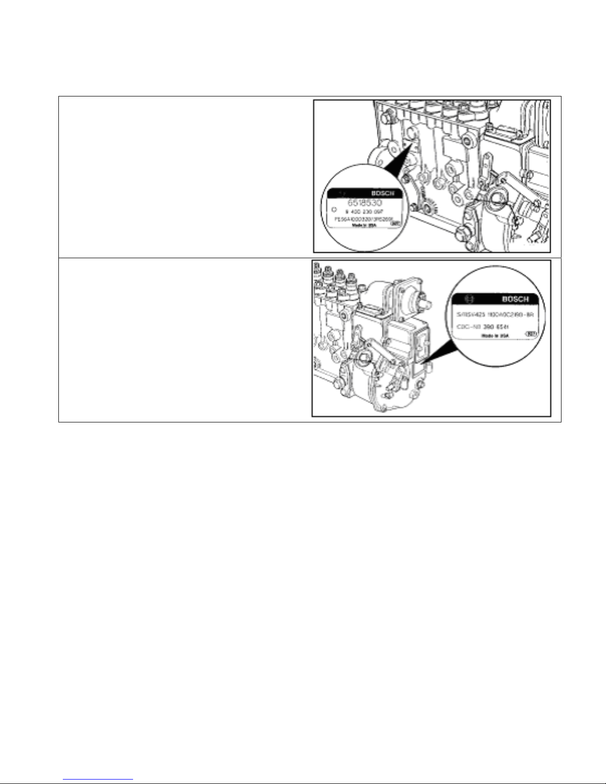
Fuel Injection Pump Dataplate
The Bosch® fuel injection pump dataplate is located
on the side of the injection pump. It provides
information for fuel pump calibration.
The Cummins part number for the fuel pumpgovernor combination is located on the governor
dataplate.
Drawing No. 9777, Section 2, Rev. 02-07
Page 30

Page 2-12 Section 2 – Engine Identification
CFP83 Series
THIS PAGE INTENTIONALLY LEFT BLANK
Drawing No. 9777, Section 2, Rev. 02-07
Page 31

Section 3 – Installation and Operation Page 3-1
CFP83 Series
Section 3 – Installation and Operation
Section Contents
Page
Installation Overview..........................................................................................................................................3-3
Physical Engine Installation ..............................................................................................................................3-4
Fuel Supply Installation .....................................................................................................................................3-6
Fire Pump Installation ........................................................................................................................................3-6
Raw Water Supply Installation ..........................................................................................................................3-7
Battery and Electrical Installation...................................................................................................................3-13
Signal and Control Installation........................................................................................................................3-14
Coolant System Preparation ...........................................................................................................................3-15
Lubricating Oil System Preparation ...............................................................................................................3-18
Fuel System Preparation..................................................................................................................................3-19
Pre-Start Inspections........................................................................................................................................3-21
Pre-Lubricate the Engine (CFP83-F10, F20, F30) ..........................................................................................3-22
Pre-Lubricate the Engine (CFP83-F40) ...........................................................................................................3-23
Lubricate Zerk Fittings on Auxiliary Drive Shaft ...........................................................................................3-24
Check Engine to Pump Alignment..................................................................................................................3-25
Initial Start-Up ...................................................................................................................................................3-26
Initial Start .........................................................................................................................................................3-34
Second Start......................................................................................................................................................3-36
Rated Speed Setpoint Adjustment (CFP83-F10, F20, F30) ...........................................................................3-37
Rated Speed Setpoint Adjustment (CFP83-F40)............................................................................................3-39
Overspeed Setpoint Adjustment and Testing................................................................................................3-41
Crank Terminate Adjustment and Testing .....................................................................................................3-45
Isolated Acceptance Testing ...........................................................................................................................3-48
Integrated Acceptance Testing .......................................................................................................................3-48
General Operating Information .......................................................................................................................3-49
Normal Remote Starting Procedure................................................................................................................3-49
Normal Local Starting Procedure ...................................................................................................................3-50
Jumpering the Batteries...................................................................................................................................3-53
Operating the Engine .......................................................................................................................................3-54
Emergency Manual Starting Procedures .......................................................................................................3-55
Emergency Manual Mode Electric Start .........................................................................................................3-56
Drawing No. 9777, Section 3, Rev. 02-07
Page 32

Page 3-2 Section 3 – Installation and Operation
CFP83 Series
Emergency Staring Manual Mode Non-Electric Start (CFP83-F10, F20, F30) ............................................ 3-58
Emergency Staring in Automatic Mode with Failed Fuel Shut-Off Solenoid............................................. 3-62
Emergency Manual Stopping Procedure....................................................................................................... 3-63
Starting Procedure - After Extended Shutdown or Oil Change .................................................................. 3-64
Drawing No. 9777, Section 3, Rev. 02-07
Page 33

Section 3 – Installation and Operation Page 3-3
CFP83 Series
Installation Overview
The first part of this section provides instructions for the initial installation, adjustment, and testing of the
Cummins NPower Fire Pump engine. Appropriate portions of this section should also be used when returning
the engine to operation after overhaul or major maintenance. The second part details normal operations.
Drawing No. 9777, Section 3, Rev. 02-07
Page 34

Page 3-4 Section 3 – Installation and Operation
CFP83 Series
Physical Engine Installation
Location
Refer to Drawing CFP83 GEN
Refer to the following drawings in Section 13 for the general fire pump engine power module assembly:
CFP83-F10, F20, F30 Drawing 8708
CFP83-F40 Drawing 8710
in Section 13 for the general fire pump and engine layout.
Model Drawing
WARNING
Do not operate a diesel engine where there are or can be combustible vapors. These vapors can be
sucked through the air intake system and cause engine acceleration and overspeeding, which can
result in a fire, an explosion, and extensive property damage. Numerous safety devices are available,
such as air intake shutoff devices, to minimize the risk of overspeeding in which an engine, because of
application, might operate in a combustible environment (from a fuel spill or gas leak, for example).
Cummins Engine Company, Inc. does not know how you will use your engine. The equipment owner and
operator, therefore, are responsible for safe operation in a hostile environment. Consult your Cummins
Authorized Repair Location for further information.
Install the fire pump engine in a sheltered environment protected from extremes of weather. Any enclosure must
protect the water supply from freezing. Ensure that the engine and electrical components are not exposed to
significant water dripping or sprays. Avoid installation in a dusty or dirty environment. Provide adequate physical
protection from other physical damage as may be present in the specific location. (Refer to National Fire
Protection Association NFPA20-2003 Chapter 11 for additional installation requirements for installations in the
USA.)
Design the installation to meet the engine’s mounting requirements. Refer to General Engine Data
Install the engine on a stable level foundation that is designed for the load and vibration of pump operation.
Install the engine with ample room for servicing of the engine, the pump, fuel supply, and support systems.
Ensure that the engine location is free of any risk of exposure to combustible vapors.
in Section 10.
Drawing No. 9777, Section 3, Rev. 02-07
Page 35

Section 3 – Installation and Operation Page 3-5
CFP83 Series
Physical Engine Installation (Cont)
Physical Installation
Use the supplied lifting hooks on the engine to
position the engine.
Provide engine support as required to support
the wet weight specified in General Engine
Data in Section 10.
Position the engine as required for the interface
with the pump, piping, and electrical
connections.
Level the installation with shims as required.
Secure the engine to the support or floor.
Connect the exhaust piping.
Drawing No. 9777, Section 3, Rev. 02-07
Page 36

Page 3-6 Section 3 – Installation and Operation
CFP83 Series
Fuel Supply Installation
NOTE: Refer to National Fire Protection Association NFPA20-2003 Chapter 11 for additional installation
requirements for installations in the USA. Ensure that the fuel system is installed in a safe and an effective
manner.
Install an elevated Diesel # 2 fuel tank or other fuel supply arrangement that meets the specifications listed in
Fuel System Specifications
in Section 10.
Install a 3/8” NPT (minimum) fuel supply line to
the fire pump engine.
Install a 1/4“ NPT (minimum) fuel return line.
Route this line to the bottom of the fuel tank in
order to minimize the return head.
Provide a pre-filter on the fuel line to the fire
pump engine.
Size the fuel tank for the maximum expected
full-load engine operation period with the initial
fuel level at the minimum level for refueling.
3/8” NPT FUEL SUPPY
1/4” NPT FUEL RETURN
Fire Pump Installation
Install the customer supplied fire pump as per the pump manufacturer’s instructions and applicable code
requirements. Refer to National Fire Protection Association NFPA20-2003 Chapter 11 for requirements for
installations in the USA. Ensure that the engine and pump are correctly aligned.
Drawing No. 9777, Section 3, Rev. 02-07
Page 37

Section 3 – Installation and Operation Page 3-7
CFP83 Series
Raw Water Supply Installation
Overview
Raw water is used to cool the engine cooling fluid. Raw water is supplied from the fire pump prior to the pump
discharge flange. It is forced through a cooling loop by fire pump pressure to the heat exchanger. In the heat
exchanger, it flows through the tubes in the bundle and is discharged to an open waste cone. The raw water
supply must be immediately available when the engine is started.
Refer to the Cooling System Flow Diagrams
system. Refer to Cooling System Specifications
Refer to Drawing 9659
Fire Power.
If the piping supplied by the customer, provide raw water supply piping and components equivalent to that can
be supplied by Cummins Fire Power and as shown in Assembly Diagram, Raw Water Piping
to National Fire Protection Association NFPA20-2003 Chapter 11 for installation requirements for installations in
the USA. When choosing the components for the raw water supply and by-pass, care must be taken to ensure
that the internal cross sectional area of the component is at least as large as the recommended pipe size.
When the raw water piping is installed, adjust both pressure regulator setpoints before operating the pump.
Damage to the heat exchanger may occur from improperly regulated raw water supply pressure.
Raw Water Supply and Drain without Cummins Raw Water Manifold (CFP83-F10, F20, and F30 Only)
NOTE: Raw water outlet piping from the heat
exchanger should be one pipe size larger than
the supply piping.
NOTE: The velocity of raw water should be as
great as possible without exceeding the
maximum shown on the appropriate engine data
sheet.
NOTE: Failure to comply will result in engine
overheat and failure.
in Section 13 for the optional raw water piping manifold that is available from Cummins
in Section 6 for a simplified block diagram of the cooling water
in Section 10 for pipe size requirements.
in Section 6. Refer
Provide raw water supply to the engine side of
the heat exchanger.
Provide an open waste cone raw water drain at
the outside of the heat exchanger.
Drawing No. 9777, Section 3, Rev. 02-07
Page 38

Page 3-8 Section 3 – Installation and Operation
CFP83 Series
Raw Water Supply Installation (Cont)
Raw Water Supply & Drain without Cummins Raw Water Manifold (CFP83-F40 Only)
NOTE: Raw water outlet piping from the heat
exchanger should be one pipe size larger than
the supply piping.
NOTE: The velocity of raw water should be as
great as possible without exceeding the
maximum shown on the appropriate engine data
sheet.
NOTE: Failure to comply will result in engine
overheat and failure.
Provide raw water supply to the Charge Air
Cooler water inlet.
Provide an open waste cone raw water drain at
the outside of the heat exchanger.
Raw Water Supply and Drain with Cummins Raw Water Manifold
NOTE: Raw water outlet piping from the
heat exchanger should be one pipe size
larger than the supply piping.
NOTE: The velocity of raw water should
be as great as possible without exceeding
the maximum shown on the appropriate
engine data sheet.
NOTE: Failure to comply will result in
engine overheat and failure.
Provide raw water supply to the raw water
manifold inlet.
Provide an open waste cone raw water
drain at the outside of the heat
exchanger.
Drawing No. 9777, Section 3, Rev. 02-07
Page 39

Section 3 – Installation and Operation Page 3-9
CFP83 Series
Check Raw Water Pressure Regulator Setpoints (CFP83-F10, F20, and F30 Only)
NOTE: Adapt this procedure to the actual
installation if a Cummins raw water manifold is
not supplied.
Temporarily remove the raw water inlet piping
from the engine coolant heat exchanger. Refer
to Drawing 9637
in Section 13.
Temporarily remove the raw water supply
piping from the fire pump to the manifold.
Temporarily supply an alternate source of raw
water to the inlet to the raw water manifold.
The temporary water supply pressure should
exceed 414 kPa [60 psig].
Drawing No. 9777, Section 3, Rev. 02-07
Page 40

Page 3-10 Section 3 – Installation and Operation
CFP83 Series
Raw Water Supply Installation (Cont)
Check Raw Water Pressure Regulator Setpoints (CFP83-F10, F20, and F30 Only) (Cont)
Provide temporary drain piping at the raw water
manifold outlet.
If closed, open the pressure gauge isolation
valve.
NOTE: The normal line has the solenoid valve.
The bypass line does not.
If open, close the normal line inlet valve.
Open the bypass line inlet and outlet valves.
Apply water pressure to the raw water
manifold.
NOTE: The heat exchanger is rated at 414 kPa
[60 psig].
Adjust the bypass pressure regulator for 414
kPa [60 psig] or slightly less.
Close the bypass line inlet valve.
NOTE: Use the correct voltage for unit.
Provide a temporary 12 VDC standard (24
VDC optional) power source for the solenoid
valve at Pin 13 and Pin 17. Refer to Drawing
10423 Sheet 1 in Section 13.
Open the normal line inlet and outlet valves.
Adjust the normal pressure regulator for 414
kPa [60 psig] or slightly less.
Remove the power jumper and reconnect the
wiring.
Re-install the raw water piping from the
manifold to the engine. Refer to Drawing 9637
in Section 13.
Test the pressure regulator setpoints with
water flowing through the heat exchanger. Trim
the setpoints if required.
Remove the temporary water supply to the
manifold.
Re-install the raw water piping at the pump.
Drawing No. 9777, Section 3, Rev. 02-07
Page 41

Section 3 – Installation and Operation Page 3-11
CFP83 Series
Raw Water Supply Installation (Cont)
Check Raw Water Pressure Regulator Setpoints (CFP83-F40 Only)
NOTE: Adapt this procedure to the actual
installation if a Cummins raw water manifold is
not supplied.
Temporarily remove raw water inlet piping at
the charge air cooler. Refer to Drawing 10712
in Section 13.
Provide temporary drain piping at the raw water
manifold outlet.
If closed, open the pressure gauge isolation
valve.
NOTE: The normal line has the solenoid valve.
The bypass line does not.
If open, close the normal line inlet valve.
Open the bypass line inlet and outlet valves.
NOTE Temporary water supply pressure
should exceed 414 kPa [60 psig].
Provide temporary water supply piping to the
raw water manifold.
Adjust the bypass pressure regulator for 414
kPa [60 psig] or slightly less.
Close the bypass line inlet valve.
NOTE: Use the correct voltage for unit.
Provide a temporary 12 VDC standard (24
VDC optional) power source for the solenoid
valve at Pin 13 and Pin 17. Refer to Drawing
10423 Sheet 1 in Section 13.
Drawing No. 9777, Section 3, Rev. 02-07
Page 42

Page 3-12 Section 3 – Installation and Operation
CFP83 Series
Raw Water Supply Installation (Cont)
Check Raw Water Pressure Regulator Setpoints (CFP83-F40 Only) (Cont)
Open the normal line inlet and outlet valves.
Adjust the normal pressure regulator for 414
kPa [60 psig] or slightly less.
Remove the power jumper and reconnect the
wiring.
Re-install the raw water piping from the
manifold to the charge air cooler. Refer to
Drawing 10712
Test the pressure regulator setpoints with
water flowing through the heat exchanger. Trim
the setpoints if required.
Remove the temporary water supply to the
manifold.
Re-install the raw water piping at the pump.
in Section 13.
Drawing No. 9777, Section 3, Rev. 02-07
Page 43

Section 3 – Installation and Operation Page 3-13
CFP83 Series
Battery and Electrical Installation
Overview
Two redundant sets of batteries must be supplied for the selected operating voltage (standard 12 VDC or
optional 24 VDC).
Batteries must meet the requirement listed in Electrical System Specifications
Batteries may be supplied by Cummins Fire Power as an option or may be supplied by the customer.
Refer to National Fire Protection Association NFPA20-2003 Chapter 11 for battery and battery charger
requirements for installations in the USA.
Battery Installation
Install the redundant sets of batteries in a well ventilated or otherwise protected location. Provide adequate
room for servicing or replacing the batteries. Provide protection from extremes of temperature and weather.
Locate the batteries near the engine or increase the size of the conductors as required by applicable codes.
Ensure that the batteries are configured properly for either 12 VDC or 24 VDC operations as appropriate.
Battery Wiring Installation
NOTE: Install the wiring in accordance with applicable codes and specifications.
Install the Loose Wire Kit wires. Refer to Drawing 9767
If purchased, install the optional battery cable kit (Cummins Fire Power Part No. 9609). Otherwise, install
equivalent customer supplied wiring.
in Section 13.
in Section 10.
Drawing No. 9777, Section 3, Rev. 02-07
Page 44

Page 3-14 Section 3 – Installation and Operation
CFP83 Series
Signal and Control Installation
NOTE: Install signal and control wiring at Terminal Board TB. Refer to Drawing 10423 Sheet 1 in Section 13.
Ensure that the fire control system is properly installed and configured as per the manufacturer’s instructions.
Complete the customer-supplied fire pump controller wiring as per the manufacturer’s instructions.
NOTE: Do not connect more than two wires at any point on the fire pump engine control panel terminal board. If
necessary, add a grounding terminal board at the fire control system.
Connect the control power from the fire pump controller at TB-1 (+) and TB-11 (-). This power source is
necessary for fire pump operations while in the AUTO mode.
Connect the two redundant crank signals from the fire pump controller to TB-9 (Crank Battery A) and to TB-10
(Crank Battery B). Connect the signal ground to TB-11.
Connect the Crank Terminate input to the fire pump controller from TB-2 with signal ground at TB-11. This 12 or
24 VDC signal is present when the engine is running. This signal indicates that the engine has started and that
the crank command from the fire pump controller should stop immediately.
Connect the remote overspeed alarm input to the fire pump controller from TB-3. This 12 or 24 VDC signal is
present when the overspeed switch has operated. If this event occurs, the fire pump engine will stop. The local
RESET button must be pressed in order to restart the engine.
Connect the Low Oil Pressure alarm input to the fire pump controller from TB-5. This 0 VDC grounded signal is
present when the oil pressure has dropped below the 110 kPa [16 PSIG] setpoint. The engine will continue to
operate but immediate attention is necessary in order to prevent excessive damage to the engine or
catastrophic engine failure.
Connect the High Water Temperature alarm input to the fire pump controller from TB-5. This 0 VDC grounded
signal is present when the engine is running and the coolant temperature has risen above the 93
o
C [200 oF]
setpoint. The engine will continue to operate but immediate attention is necessary in order to prevent excessive
damage to the engine or catastrophic engine failure.
If used, provide permanently installed redundant battery charging systems with connections at TB 6 and TB-8
(+) and TB-11 (-). TB-6 (+) and TB-8 (+) and TB-11 (-) should also be used for remote battery voltage
indications at the fire control system or elsewhere.
Ensure electrical continuity and adequate insulation resistance for the installed wiring.
Provide the initial charge on the redundant batteries as per the battery charger’s instructions.
Check that both voltmeters on the local control panel indicate the approximate battery voltage.
Drawing No. 9777, Section 3, Rev. 02-07
Page 45

Section 3 – Installation and Operation Page 3-15
CFP83 Series
Coolant System Preparation
Check Cooling System Integrity
NOTE: Refer to Drawing 8708
F20, F30) or Drawing 8710
Section 13 for hose arrangement.
Check that all coolant hoses are properly
installed and that the clamps are tight.
Check that the coolant drain petcock is closed.
(CFP83-F10,
(CFP83-F40) in
CAUTION
The valve must be in the ON position to
prevent engine damage.
Check that the coolant filter valve is open. If
required, turn the shutoff to the ON position by
rotating the knob from horizontal to vertical in
the direction shown.
CFP83-F10, F20, F30 Only
Open the aftercooler coolant vent.
Drawing No. 9777, Section 3, Rev. 02-07
Page 46

Page 3-16 Section 3 – Installation and Operation
CFP83 Series
Coolant System Preparation (Cont)
Add Coolant
Remove the pressure cap from the heat
exchanger.
Refer to Cooling System Specifications and
Coolant Recommendations and Specifications
in Section 10.
NOTE: Use a mixture of at least 50 percent
antifreeze and 50 percent water.
NOTE (CFP83-F10, F20, F30 Only): Close the
coolant vent when coolant level reaches the
vent.
Add coolant until the coolant level is just below
the fill tube in the coolant heat exchanger.
Check for leaks. Correct any leaks.
Install the pressure cap on the heat exchanger.
Check Raw Water Supply Lineup
CAUTION
The raw water lines to and from the fire
pump must be open, and there must be
sufficient water to the heat exchanger when
the engine has started. Insufficient water
supply will cause overheating, resulting in
engine failure.
Check that the pressure gauge isolation valve
is open.
Drawing No. 9777, Section 3, Rev. 02-07
Page 47

Section 3 – Installation and Operation Page 3-17
CFP83 Series
Coolant System Preparation (Cont)
NOTE: The right line is the bypass line. The left
line with the solenoid valve is the normal line.
Check that the bypass line outlet valve is
closed.
Check that the normal line inlet valve is open.
Check that the normal line outlet valve is open.
Drawing No. 9777, Section 3, Rev. 02-07
Page 48

Page 3-18 Section 3 – Installation and Operation
CFP83 Series
Lubricating Oil System Preparation
Add Lubricating Oil
NOTE: For oil requirements, refer to Lubricating
Oil System Specifications and Lubricating Oil
Recommendations and Specifications in Section
10. No change in oil viscosity or type is needed
for new or newly rebuilt engines.
Fill the crankcase with lubricating oil to the “H”
(high) mark on the dipstick.
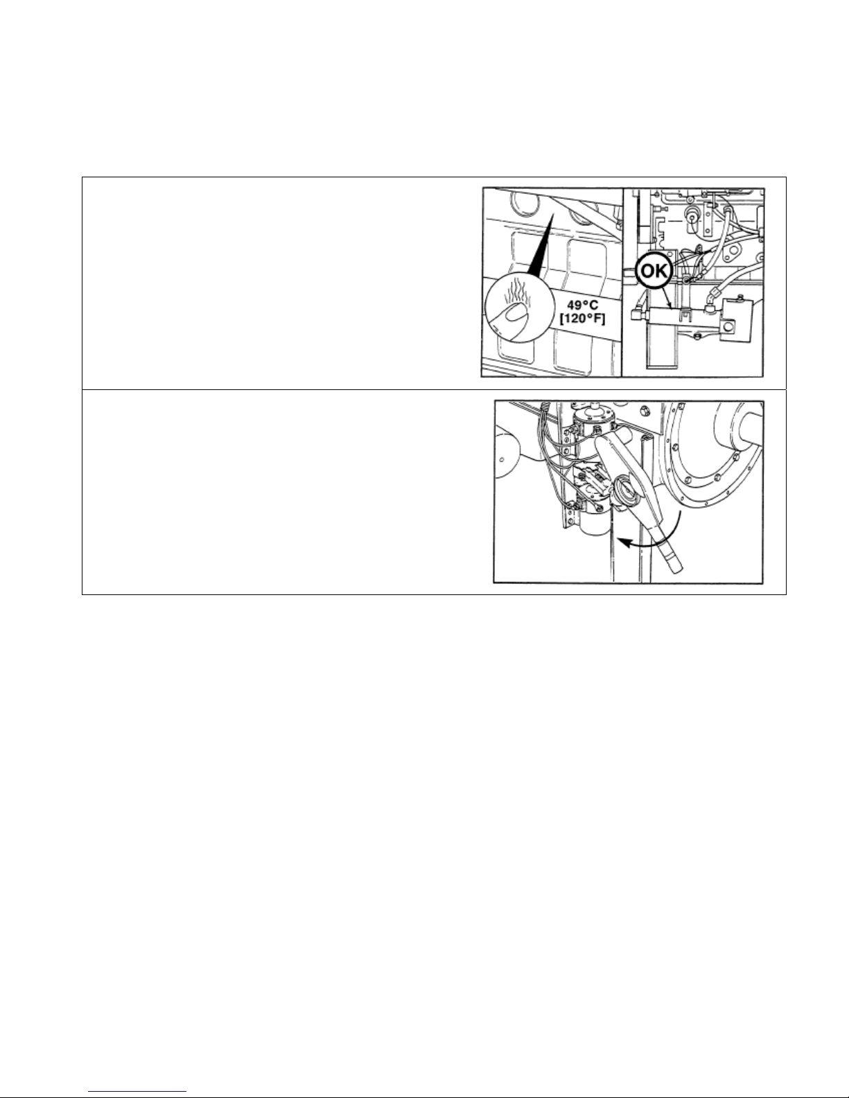
Prime the Turbocharger
CAUTION
New turbochargers must be pre-lubricated
before startup. Failure to pre-lube the
turbochargers will result in turbocharger
bearing failure.
Remove the air intake filter assembly. Refer to
Intake Air Filter Removal/Installation
7.
Remove the turbocharger oil inlet line from the
turbocharger bearing housing.
in Section
NOTE: Rotate the turbine wheel to allow oil to
enter the bearing housing. Any excess oil will
drain through the oil drain line.
Lubricate the bearings by pouring 59 to 89 ml [2
to 3 oz] of clean engine lubricating oil into the
turbocharger oil supply line fitting.
Tighten the oil supply line.
Torque Value: 24 N•m [18 ft-lb]
Install the air intake filter assembly. Refer to
Intake Air Filter Removal/Installation
7.
in Section
Drawing No. 9777, Section 3, Rev. 02-07
Page 49

Section 3 – Installation and Operation Page 3-19
CFP83 Series
Fuel System Preparation
Fill the Fuel Filter
Unscrew the combination fuel filter assembly
and remove it from the engine.
If open, close the water separator drain cock.
Refer to Drain Fuel-Water Separator
Section 5.
in
Lubricate the o-ring seal with clean
lubricating oil.
NOTE: Refer to Fuel Recommendations and
Specifications in Section 10 for fuel
requirements.
Fill the fuel element with fuel.
CAUTION
Mechanical over-tightening will distort the
threads, filter element seal or filter can.
Install the filter on the filter head.
Tighten the filter until the gasket contacts the
filter head surface.
Tighten the filter an additional one-half to
three-fourths of a turn, or as specified by the
filter manufacturer.
Drawing No. 9777, Section 3, Rev. 02-07
Page 50

Page 3-20 Section 3 – Installation and Operation
CFP83 Series
Fuel System Preparation (Cont)
Fill the Fuel Tank
Check that the fuel tank and piping is clean.
Fill the fuel tank with Number 2 Diesel fuel.
Bleed the air from the fuel supply line to the
fire pump engine.
Fill the fuel lines to the engine and fill the fuel
pre-filter.
Tighten all fuel supply line fittings to stop
possible suction leaks.
Bleed the Engine Fuel Lines
Loosen the banjo connector bleed screw at
the fuel filter housing.
Operate the plunger on the fuel lift pump until
the fuel flowing from the fitting is free of air.
Tighten the bleed screw.
Torque Value: 9 N•m [80 in-lb]
Drawing No. 9777, Section 3, Rev. 02-07
Page 51

Section 3 – Installation and Operation Page 3-21
CFP83 Series
Pre-Start Inspections
Perform a visual inspection as follows:
• Check that there is no apparent damage and that all components are installed.
• Check that the drive belt is properly installed.
• Check that all hoses and tubes are properly installed.
• Check that all electrical connections are properly installed.
• Check that the fire pump is properly installed as per the pump manufacturer’s instructions, is correctly
aligned, and is free to rotate.
Drawing No. 9777, Section 3, Rev. 02-07
Page 52

Page 3-22 Section 3 – Installation and Operation
CFP83 Series
Pre-Lubricate the Engine (CFP83-F10, F20, F30)
Disconnect the connector at the electric fuel
solenoid (Fuel Shutoff Valve).
Press the MANUAL position on the
AUTO/MANUAL rocker switch.
NOTE: Monitor engine oil pressure on the local
control panel. Some pressure indication is
expected. Also, the low oil pressure light should
go off.
Crank the engine about two revolutions using
either the CRANK BATT A or the CRANK BATT
B switch positions.
Repeat a second time if oil pressure did not
register on the gauge.
NOTE: Troubleshoot as per Lubricating Oil
Pressure Low in Section 12 if oil pressure did not
register on the gauge.
When pre-lubrication has been accomplished,
reconnect the connector at the fuel injection
pump solenoid (Fuel Shutoff Valve).
Drawing No. 9777, Section 3, Rev. 02-07
Page 53

Section 3 – Installation and Operation Page 3-23
CFP83 Series
Pre-Lubricate the Engine (CFP83-F40)
Check content, option info not found/available
Disconnect the connector at the electric fuel
solenoid.
Press the MANUAL position on the
AUTO/MANUAL rocker switch.
NOTE: Monitor engine oil pressure on the local
control panel. Some pressure indication is
expected.
Crank the engine about two revolutions using
either the CRANK BATT A or the CRANK BATT
B switch positions.
Repeat a second time if oil pressure did not
register on the gauge.
NOTE: Troubleshoot as per Lubricating Oil
Pressure Low in Section 12 if oil pressure did not
register on the gauge.
When pre-lubrication has been accomplished,
reconnect the connector at the fuel injection
pump solenoid.
Drawing No. 9777, Section 3, Rev. 02-07
Page 54

Page 3-24 Section 3 – Installation and Operation
CFP83 Series
Lubricate Zerk Fittings on Auxiliary Drive Shaft
Some lubrication loss may occur during
transport and storage. It is recommended
that all drive shafts be re-lubricated upon
installation.
Grease zerk fittings as shown.
See Lubricating Oil Recommendations
and Specifications in Section 10 for
grease specifications.
Drawing No. 9777, Section 3, Rev. 02-07
Page 55

Section 3 – Installation and Operation Page 3-25
CFP83 Series
Check Engine to Pump Alignment
Ensure engine position is centered on
Frame side to side within +-1/32”, by
measuring outside of frame side to engine
support leg mounting pad. (Compare two
front engine supports and Two back
engine supports).
Align engine centerline to pump centerline
within +-1/32”.
The pump centerline to the engine crank
centerline (in vertical plane) is to be ½”
+0, -1/4” offset.
NOTE: The slip joint must rest in the
middle third of its travel when installed.
Auxiliary Drive shaft mounting flanges
must be parallel within 1.5 degrees.
SIDE VIEW
90°
90°
TOP VIEW
Drawing No. 9777, Section 3, Rev. 02-07
Page 56

Page 3-26 Section 3 – Installation and Operation
CFP83 Series
Initial Start-Up
NOTE: Contact personnel responsible for the fire protection system before starting and to obtain approval to
service or repair the system.
Check the Raw Water Valves
CAUTION
The raw water lines to and from the fire
pump must be open, and there must be
sufficient water to the heat exchanger when
the engine has started. Insufficient water
supply will cause overheating, resulting in
engine failure.
Align raw water supply to the raw water supply
valves.
Align drainage from the heat exchanger raw
water outlet.
Open the raw water supply valves as shown.
Check the Engine Coolant Supply
Close all cooling system drains.
Verify that the vents are opened.
Drawing No. 9777, Section 3, Rev. 02-07
Page 57

Section 3 – Installation and Operation Page 3-27
CFP83 Series
Initial Start-Up (Cont)
Remove the coolant tank cap.
Check coolant level.
Cold coolant level should be between the bottom
of the tube and above the top of the heat
exchange coils.
Add coolant if necessary. Use a mixture of at
least 50 percent antifreeze and 50 percent
water.
Replace the coolant tank cap.
Make a visual check for coolant leaks.
Prime the Fuel System:
Fill the fuel filter (see Fuel Recommendations
and Specifications in Section 10).
Remove the fuel pump suction line and wet the
gear pump gears with clean lubricating oil.
Check and fill the fuel tanks.
Check the injectors to be sure they are properly
adjusted.
Drawing No. 9777, Section 3, Rev. 02-07
Page 58

Page 3-28 Section 3 – Installation and Operation
CFP83 Series
Initial Start-Up (Cont)
Check Initial Crankcase Oil Level:
CAUTION
Never operate the engine with the oil level
below the low (“L”) mark or above the high
(“H”) mark on the dipstick
Check the oil level.
NOTE: No change in oil viscosity or type is
needed for new or newly rebuilt engines.
If below the low mark, fill the crankcase to the
low “L” (low) mark on the dipstick.
See Lubricating Oil Recommendations and
Specifications in Section 10 for oil specifications.
See the Lubricating Oil System
quantity that may be required.
Pre-Lubricate the Turbocharger:
Specification for
CAUTION
New turbochargers must be pre-lubricated
before startup. Failure to pre-lube the
turbochargers will result in turbocharger
bearing failure.
Remove the turbocharger oil inlet line.
Pre-lubricate the housing by adding 50 to 60
cc (2 to 3 oz.) of clean engine lubricating oil.
Replace the line.
Pre-Lubricate the Engine
NOTE: Do not prime the engine lubricating
system from the by-pass filter.
On the top of the fuel pump, disconnect the
electric fuel solenoid. Make sure that the fuel
pump solenoid wire terminal does not touch
the engine.
Close the fuel shutoff valve from the fuel
tank to prevent the engine from starting.
Prime the engine lubricating system until a
30 psi [207 kPa] minimum pressure is
obtained.
Drawing No. 9777, Section 3, Rev. 02-07
Page 59

Section 3 – Installation and Operation Page 3-29
CFP83 Series
Initial Start-Up (Cont)
NOTE: Use the fire pump controller or manual
setting from the gauge panel to crank the engine
through two cranking cycles.
Crank the engine at least 15 seconds, while
maintaining the external oil pressure at a
minimum of 15 psi [103kPa].
CAUTION
Never operate the engine with the oil level
below the low (“L”) mark or above the high
(“H”) mark on the dipstick
Check the oil level again.
Drawing No. 9777, Section 3, Rev. 02-07
Page 60

Page 3-30 Section 3 – Installation and Operation
CFP83 Series
Initial Start-Up (Cont)
NOTE: No change in oil viscosity or type is
needed for new or newly rebuilt engines.
If below the high mark, fill the crankcase to the
high “H” (high) mark on the dipstick.
See Lubricating Oil Recommendations and
Specifications in Section 10 for oil specifications.
See the Lubricating Oil System
quantity that may be required.
Initial Test Run
Move the throttle lever to mid-speed position.
Start the engine.
Specification for
Immediately move the throttle to the low idle
position.
Allow the engine to operate at low idle speed
(700 RPM).
Check the lubricating oil pressure within 15
seconds after the engine starts.
Operate the engine at set point for 8 to 10
minutes.
Check for leaks, unusual noises, or other
indications of incorrect operation. Shut off the
engine and correct any problems found during
the inspection before proceeding.
After 8 to 10 minutes, stop the engine.
Check the engine oil and expansion tank
coolant levels. Top off if necessary.
Clean the raw water strainer.
Drawing No. 9777, Section 3, Rev. 02-07
Page 61

Section 3 – Installation and Operation Page 3-31
CFP83 Series
Initial Start-Up (Cont)
Supplemental Test Run
Start the engine.
Bring it to the fire pump
required operating speed.
Adjust the raw water pressure
regulator to obtain the required
pressure.
Readjust the engine speed if
necessary.
Overspeed Adjustment
Procedure:
NOTE: Overspeed is already
set at factory.
Remove the calibrating screw
cover from the electronic
overspeed switch.
Turn the small screw on the
potentiometer near the word
“OVERSPEED” clockwise to
increase trip speed.
Move the throttle to the half
throttle position. Start the
engine and move the throttle
to the minimum position.
Drawing No. 9777, Section 3, Rev. 02-07
Page 62

Page 3-32 Section 3 – Installation and Operation
CFP83 Series
Initial Start-Up (Cont)
NOTE: Test button triggers overspeed at 10%
below normal.
Depress the “TEST” button push-button on the
inside of the panel.
Turn the screw to increase speed.
Verify overspeed trip/indications.
Operate the RESET switch on the front of the
engine control panel.
Repeat if necessary to further adjust the
overspeed stop setting.
Start the engine.
Check operation at rated speed.
Shut off the engine.
Press the “AUTO” button so the fire pump will
be ready to start automatically.
Drawing No. 9777, Section 3, Rev. 02-07
Page 63

Section 3 – Installation and Operation Page 3-33
CFP83 Series
Initial Start-Up (Cont)
Completion
Support fire pump testing as per NFPA or
applicable requirements.
Contact operating personnel responsible for
fire protection system that engine is ready for
service.
Obtain authorized signature of acceptance.
Drawing No. 9777, Section 3, Rev. 02-07
Page 64

Page 3-34 Section 3 – Installation and Operation
CFP83 Series
Initial Start
NOTE: The object of this test is to check that the engine starts and operates normally with oil pressure being
displayed and raw water flow being established to the coolant heat exchanger. Operation at the factory-adjusted
rated speed is also checked.
NOTE: If the engine does not start, vent the fuel
system. Refer to Air in Fuel
in Section 7, for
instructions on how to vent the fuel system.
NOTE: If the engine still will not start,
troubleshoot as per Engine Cranks But Will Not
Start (No Exhaust Smoke) or Engine Difficult to
Start or Will Not Start - Exhaust Smoke Present
in Section 12.
NOTE: When the engine starts, immediately
check that oil pressure is displayed. It should be
on-scale within a few seconds. Stop the engine if
oil pressure is not displayed within about 15
seconds.
NOTE: When the engine starts, immediately
check that raw water flow is established through
the coolant heat exchanger. Raw water flow
should be established immediately but some
delay may occur before the flow exits the heat
exchanger drain connection.
NOTE: Rated speed is displayed on the Factory
Setting Tag described in Section 2.
NOTE: If the engine fully loaded, it should
operate at rated speed. Unloaded, it may operate
about 10% faster. If it becomes necessary to
adjust the engine’s actual speed to match the
rated value, refer to Rated Speed Setpoint
Adjustment (CFP83-F10, F20, F30) or Rated
Speed Setpoint Adjustment (CFP83-F40) in this
section.
FACTORY SETTING
ENGINE SPEED SETTING:
(@ HP SETTING)
OVERSPEED SWITCH SETTIN G:
Drawing No. 9777, Section 3, Rev. 02-07
Page 65

Section 3 – Installation and Operation Page 3-35
CFP83 Series
Initial Start (Cont)
Start the engine using either the CRANK BATT A
or the CRANK BATT B switch positions.
Check that the engine starts and operates at
about rated speed.
NOTE: If oil pressure is not present or if the Low
Oil Pressure Light does not go out, stop the
engine and troubleshoot as per Lubricating Oil
Pressure Low in Section 12.
Check that lubricating oil pressure is displayed
within 15 seconds after the engine starts.
NOTE: Raw water should be flowing through the
heat exchanger and water pressure shown on the
local pressure gauge should be no more than
414 kPa (60 psig).
Check that raw water is flowing through the heat
exchanger.
Check that raw water supply pressure is correctly
adjusted.
Operate the engine for 8 to 10 minutes.
Check for leaks, unusual noises, or other
indications of incorrect operation.
Shut off the engine by pressing the AUTO
position on the AUTO/MANUAL rocker switch
and by momentarily pressing the RESET switch.
Check that raw water flow stops automatically
shortly after the engine stops.
Correct any problems found during the inspection
before proceeding.
Check the engine lubricating oil level. Refer to
Check Lubricating Oil Level
if necessary.
Check the coolant heat exchanger’s coolant
level. Refer to Check Coolant Leve
Top off if necessary.
Check the raw water strainer. Clean the strainer if
necessary.
in Section 5. Top off
l in Section 5.
Drawing No. 9777, Section 3, Rev. 02-07
Page 66

Page 3-36 Section 3 – Installation and Operation
CFP83 Series
Second Start
The object of this test is to check that the engine operates normally with coolant temperature being maintained.
Oil pressure is checked at rated speed.
NOTE: Adjust engine operating speed as per
Rated Speed Setpoint Adjustment
below.
Start the engine and observe that it is operating
at rated speed.
Check that the oil pressure is as specified in
Lubricating Oil System Specifications
in Section
10.
NOTE: If oil pressure is not within the rated
range, troubleshoot as per Lubricating Oil
Pressure High or Lubricating Oil Pressure Low in
Section 12.
NOTE: If temperature does not stabilize, stop the
engine and refer to Coolant Temperature Above
Normal or Coolant Temperature Below Normal
(Engine Running) in Troubleshooting Section 12.
Check that engine operating temperature
stabilizes between about 82 and 95
o
203
F].
o
C [180 and
Shut off the engine.
Correct any problems found before proceeding.
Check the engine lubricating oil level. Refer to
Check Lubricating Oil Level
in Section 5. Top off
if necessary.
Check the coolant heat exchanger’s coolant
level. Refer to Check Coolant Level
in Section 5.
Top off if necessary.
Check the raw water strainer. Clean the strainer if
necessary.
Drawing No. 9777, Section 3, Rev. 02-07
Page 67

Section 3 – Installation and Operation Page 3-37
CFP83 Series
Rated Speed Setpoint Adjustment (CFP83-F10, F20, F30)
NOTE: If required, use this section to adjust the normal operating speed to the nameplate value.
NOTE: Rated speed is displayed on
the Factory Setting Tag
described in
Section 2.
Start the engine.
Observe that the engine starts and
accelerates the currently adjusted
speed setpoint.
Adjust the speed setpoint to rated
speed.
FACTORY SETTING
FACTORY SETTING
ENGINE SPEED SETTING:
(@ HP SETTING)
OVERSPEED SWITCH SETTIN G:
NOTE: Rated speed is adjusted by
locating the threaded linkage rod on
the fuel pump side of the engine.
Drawing No. 9777, Section 3, Rev. 02-07
Page 68

Page 3-38 Section 3 – Installation and Operation
CFP83 Series
Rated Speed Setpoint Adjustment (CFP83-F10, F20, F30) (Cont)
To increase the rated speed, turn the
bolt on the right side of the throttle
bracket clockwise The adjustment of
the bolt will pivot the throttle bracket
counter-clockwise and will allow more
fuel through the pump to speed up the
engine.
Loosen the lock nut and turn bolt
clockwise to allow for more RPM
speed. When rated speed is correct,
tighten lock nut against stop.
To decrease the speed, turn the bolt
counter-clockwise on the right side of
the throttle bracket. The adjustment of
the bolt will pivot the throttle bracket
clockwise and will allow less fuel to
flow through the pump to slow down
the engine.
When rated speed is correct, tighten
the locking nuts against the stops.
The threaded bolt on the left side of
the bracket is for maximum speed
and may also need to be adjusted if
maximum speed cannot be reached.
The same adjustment sequence can
be performed for maximum speed
adjustment.
Rated speed adjustment
8708-cfp 83
Stop the engine.
Start the engine.
Observe that the engine starts and
accelerates to the rated speed
setpoint.
Stop the engine. Repeat the above
adjustment until the desired speed is
attained.
Drawing No. 9777, Section 3, Rev. 02-07
Page 69

Section 3 – Installation and Operation Page 3-39
CFP83 Series
Rated Speed Setpoint Adjustment (CFP83-F40 Only)
NOTE: If required, use this section to adjust the normal operating speed to the nameplate value.
NOTE: Rated speed is displayed on
the Factory Setting Tag
described
in Section 2.
Start the engine.
Observe that the engine starts and
accelerates the currently adjusted
speed setpoint.
Adjust the speed setpoint to rated
speed.
FACTORY SETTING
ENGINE SPEED SETTING:
(@ HP SETTING)
OVERSPEED SWITCH SETTIN G:
Drawing No. 9777, Section 3, Rev. 02-07
Page 70

Page 3-40 Section 3 – Installation and Operation
CFP83 Series
Rated Speed Setpoint Adjustment (CFP83-F40) (Cont)
To increase the rated speed, turn
the bolt clockwise on the right side
of the throttle bracket. The
adjustment of the bolt will pivot the
throttle bracket to allow more fuel
through the pump to speed up the
engine.
The nut on the right, closest to the
bracket will need to be tightened to
lock in the adjusted speed set point.
Loosen lock nuts and turn threaded
bolt clockwise to allow for more
RPM speed. When rated speed is
correct, tighten lock nut against
stop.
To decrease the speed, turn the
threaded bolt counter-clockwise.
The adjustment of the bolt in a
counter-clockwise direction will
allow less fuel to flow through the
pump to slow down the engine.
Rated speed adjustment
8708-cfp 83
When rated speed is correct,
tighten the locking nut against the
stops.
Stop the engine.
Start the engine.
Observe that the engine starts and
accelerates to the rated speed
setpoint.
Stop the engine. Repeat the above
adjustment until the desired speed
is attained.
Drawing No. 9777, Section 3, Rev. 02-07
Page 71

Section 3 – Installation and Operation Page 3-41
CFP83 Series
Overspeed Setpoint Adjustment and Testing
Overview
Overspeed setpoint adjustment and testing is a repetitive process. Use the Adjustment Procedure
setpoint. Use the Test Procedure
to check the setpoint. Repeat the adjustments and checks until the desired
to change the
setpoint is demonstrated. When the overspeed setpoint is successfully demonstrated, then check that the
engine operates normally while not being tested.
NOTE: The overspeed trip setpoint is displayed
on the Factory Setting Tag described in Section
FACTORY SETTING
2.
NOTE: The overspeed setpoint must be set at
between 115 and 120% of the engine’s rated
speed.
ENGINE SPEED SETTING:
(@ HP SETTING)
OVERSPEED SWITCH SETTIN G:
The speed switch located on the engine’s local
control panel has a TEST button which lowers
the currently adjusted overspeed by 10%. Thus,
an overspeed setpoint of 2112 rpm would be
reduced to (2112 * 0.9 =) 1901 RPM when the
test button is pressed.
Adjust the Speed Switch:
Lower the cover on the engine’s local control
panel.
Disconnect the engine speed sensor signal from
PICK-UP terminals 1 and 2.
Connect a signal generator capable of providing
between 0.25 to 120 VAC RMS signal to the
switch. The signal must be proportional to the
engine’s rated speed.
Provide an overspeed signal at the specified
overspeed switch setting frequency.
Drawing No. 9777, Section 3, Rev. 02-07
Page 72

Page 3-42 Section 3 – Installation and Operation
CFP83 Series
Overspeed Setpoint Adjustment and Testing (Cont)
Remove the calibrating screw cover from the
electronic overspeed switch.
NOTE: Turn the small screw on the
potentiometer near the word “OVERSPEED”
clockwise to increase trip speed. Turn it counterclockwise to reduce trip speed.
If the OVERSPEED light is illuminated with the
signal present, perform the following steps:
Reduce the signal frequency.
Press the RESET button.
Turn the potentiometer clockwise to raise the
setpoint.
Increase the signal frequency to setpoint.
With the OVERSPEED light off, slowly turn the
potentiometer counter-clockwise until the light is
just illuminated.
NOTE: Repeat the adjustments as required to
make the finest adjustment practical.
When the setpoint is adjusted, perform the
following steps:
Replace the screw cover at the potentiometer.
Disconnect the signal generator.
Reset the light.
Reconnect the speed sensor input.
Perform the Test Procedure
the effect of the adjustment.
as outlined to check
Drawing No. 9777, Section 3, Rev. 02-07
Page 73

Section 3 – Installation and Operation Page 3-43
CFP83 Series
Overspeed Setpoint Adjustment and Testing (Cont)
Test Procedure
NOTE: The overspeed trip setpoint is displayed
on the Factory Setting Tag
described in Section
2.
Start the engine.
Observe that the engine starts and operates at
about rated speed.
NOTE: Monitor engine speed on the tachometer.
Record the observed engine speed when it trips.
It must trip between 115 and 120% of rated
speed.
NOTE: Do not exceed 120% of rated speed. If
the engine does not trip at or below 120%, stop
the engine and Adjust the Speed Switch
.
Adjust the mechanical throttle adjustment to
increase engine speed to the setpoint.
FACTORY SETTING
FACTORY SETTING
ENGINE SPEED SETTING:
(@ HP SETTING)
OVERSPEED SWITCH SETTIN G:
Observe that the engine stops automatically and
that the overspeed trip light is illuminated.
Verify that the engine tripped at a speed between
115 and 120% of rated speed.
Press the RESET button on the speed switch.
Press the RESET switch on the front of the
engine control panel.
Observe that the overspeed light has
extinguished.
NOTE: If required by the local authority, restart
the engine at the current mechanical throttle
setpoint to demonstrate a run-away overspeed
shutdown as specified by Underwriter’s
Laboratory UL 1247.
Drawing No. 9777, Section 3, Rev. 02-07
Page 74

Page 3-44 Section 3 – Installation and Operation
CFP83 Series
Overspeed Setpoint Adjustment and Testing (Cont)
Set/Check Normal Operation
Start the engine.
Adjust engine speed for rated value. Refer to
Rated Speed Setpoint Adjustment (CFP83-F10,
F20, F30) or Rated Speed Setpoint Adjustment
(CFP83-F40) in this section.
Stop the engine.
Drawing No. 9777, Section 3, Rev. 02-07
Page 75

Section 3 – Installation and Operation Page 3-45
CFP83 Series
Crank Terminate Adjustment and Testing
NOTE: The crank terminate signal to the remote fire pump controller informs the controller that the engine has
started. This allows the controller to terminate the selected crank signal to the engine. This crank terminate
signal is produced by the overspeed switch in the engine’s local control panel. The setpoint for the crank
terminate signal is adjusted at the factory to a value above normal idling speeds but less than the rated speed.
The setpoint should not require adjustment unless it is necessary to test the switch operation or to replace the
overspeed speed switch.
NOTE: If using this procedure for troubleshooting, perform the test portion prior to making any adjustments.
Verify automatic reset of the crank terminate signal.
Prepare
Place the fire protection system in a safe mode
for engine service.
Place the AUTO/MANUAL rocker switch in the
MANUAL position.
REMOVE BATTERY POWER BEFORE
SERVICING ENGINE OR CONTROLS
For safety reasons, both batteries must be
disconnected before performing service on the
Firepump Engine or on any of its controls.
Before disconnecting the batteries, place the
Firepump Controller in its appropriate service
position in order to avoid a “Battery Failure”
alarm.
Wear safety glasses when disconnecting
batteries!
Next, disconnect both batteries at their terminals.
Drawing No. 9777, Section 3, Rev. 02-07
Page 76

Page 3-46 Section 3 – Installation and Operation
CFP83 Series
Crank Terminate Adjustment and Testing (Cont)
Adjust
NOTE: Refer to Drawing 10423 Sheet 1
Section 13.
Open the engine’s local control panel cover.
Disconnect the GRAY/RED (MPU +) wire from
PICK-UP terminal 1 at the speed switch.
Disconnect the GRAY/BLK (MPU -) wire from
PICK-UP terminal 1 at the speed switch.
Connect a signal or pulse generator to the switch
inputs with the same signal polarity.
Adjust the pulse generator to about 1100 cycles
or pulses per second.
Remove the cover from the speed switch
CRANK/TACH CAL potentiometers.
If, with this signal, the CRANK LED is illuminated
on the speed switch, turn the CRANK
potentiometer E5 clockwise until the LED
extinguishes.
Then, turn the CRANK potentiometer E5 slowly
counterclockwise until the CRANK LED
illuminates.
in
Replace the cover on the speed switch.
Remove the signal generator.
Connect the GRAY/RED (MPU +) wire at PICKUP terminal 1 at the speed switch.
Connect the GRAY/BLK (MPU -) wire at PICKUP terminal 1 at the speed switch.
Drawing No. 9777, Section 3, Rev. 02-07
Page 77

Section 3 – Installation and Operation Page 3-47
CFP83 Series
Crank Terminate Adjustment and Testing (Cont)
For safety reasons, both batteries must be reconnected before putting the engine and fire
protection system controller back in service.
Wear safety glasses when reconnecting
batteries!
Reconnect the batteries at their terminals after all
service work has been completed.
Test
NOTE: Monitor fire pump controller operations
from the controller. Check for the crank terminate
signal at the input terminals and observe that the
controller removes the crank output to the
engine.
Connect a digital voltmeter at crank terminate
output of the local control panel between TB2 (+)
and TB11 (-). Refer to Drawing 10423 Sheet 1
Section 13.
NOTE: The engine’s rated speed is displayed on
the Factory Setting Tag
Place the AUTO/MANUAL rocker switch in the
AUTO position.
Start the engine from the fire pump controller.
Observe that the engine starts and accelerates to
about rated speed.
Observe that the CRANK terminal LED on the
speed switch is illuminated.
Check that the local digital voltmeter indicates the
12 VDC standard (24 VDC optional) signal output
voltage.
described in Section 2.
in
When testing is done, stop the engine.
Remove the digital voltmeter.
Close the cover on the engine control panel.
Drawing No. 9777, Section 3, Rev. 02-07
Page 78

Page 3-48 Section 3 – Installation and Operation
CFP83 Series
Isolated Acceptance Testing
Demonstrate the manual local start, operation, and shutdown of the fire pump from the engine’s local startersolenoid controls. Demonstrate that the engine will operate in the event of blown fuses or other faults in the local
control panel. Demonstrate manual engine speed control. Manual raw water valve operations are required.
Demonstrate the manual local start, operation, and shutdown of the fire pump from the engine’s control panel.
Demonstrate that the engine starts, operates at speed, and stops in the event that the fire pump controller is not
functioning.
Demonstrate the start of the fire pump engine using each battery set separately.
Demonstrate that the fire pump engine alternator operates while the engine is running. Demonstrate that any
customer supplied battery charging systems operate when the engine is not running.
Integrated Acceptance Testing
Demonstrate the start-up, operation, and shutdown of the fire pump engine in response to operations of the
customer-installed fire pump controller. Perform this testing with the testing of the fire pump controller.
Demonstrate that the fire pump controller provides design indications and/or alarms for simulated engine oil
pressure, water temperature, and overspeed faults.
Demonstrate the actual operation of the crank terminate output from the overspeed switch.
Participate in any flushing, pressure testing, flow testing, or capacity testing required for the fire protection
system.
Complete the Cummins Fire Power Start-Up Inspection (SUI) Checklist. This is available on the Cummins Fire
Power web site (www.cumminsfirepower.com/startup).
When these items have been demonstrated, contact operating personnel responsible for fire protection system
that engine is ready for service.
Drawing No. 9777, Section 3, Rev. 02-07
Page 79

Section 3 – Installation and Operation Page 3-49
CFP83 Series
General Operating Information
Cummins fire pumps are tested before being shipped from the factory and are ready to put to work in application
regarding to fire emergencies.
Correct care of your engine will result in longer life, better performance, and more economical operation.
Follow the daily maintenance checks listed in Maintenance Guidelines
Check the water temperature and oil pressure indicators, warning lights, and other gauges daily to make sure
they are operational.
, Section 4.
Normal Remote Starting Procedure
The fire pump engine starts automatically upon receipt of the start command from the customer installed fire
control panel. The remote command starts the engine when the AUTO/MANUAL rocker switch at the local;
control panel is in the AUTO position. The remote start command consists of either the Crank A or the Crank B
signal. Only one should be selected.
The engine continues to operate as long as the run signal is present. When the run signal is lost, the engine
promptly stops.
When the engine starts, the crank terminate signal is sent to the fire control panel to indicate that the engine is
running. How this is displayed depends upon the fire control panel manufacturer. This indication should be
checked in the event that an automatic start is initiated. If the signal is not present, the engine can be started
locally by using the Emergency Starting Procedure
The engine may be stopped locally by selecting the manual position on the AUTO/MANUAL rocker switch and
by pressing the local RESET switch.
in this section.
Drawing No. 9777, Section 3, Rev. 02-07
Page 80

Page 3-50 Section 3 – Installation and Operation
CFP83 Series
Normal Local Starting Procedure
Overview
The fire pump engine is started locally for testing and maintenance. Local starts for testing will be performed at
rated speed. That is, the engine starts and promptly ramps up to operating speed. If it is necessary to operate
the engine at idle speed for maintenance or troubleshooting, the engine speed must be manually reduced. After
maintenance or troubleshooting, the speed must be manually reset to the rated value shown on the Factory
Setting Tag in see Section 2.
Local Starting Procedure for Testing
CAUTION
To prevent damage to the starter, do not engage the starting motor more than 15 seconds. Wait 15
seconds between each attempt to start (electrical starting motors only).
Start the Engine
Press the MANUAL position on the
AUTO/MANUAL rocker switch.
Observe the battery voltages displayed on the
engine control panel. Use the battery with the
highest indicated voltage.
NOTE: Depress the selected switch for up to 15
seconds or until the engine starts. Repeat up to
three times if necessary.
Start the engine using either the CRANK BATT A
or the CRANK BATT B rocker switch positions.
NOTE: If the engine does not start after three
attempts, check the fuel supply system. Absence
of blue or white exhaust smoke during cranking
indicates no fuel is being delivered.
Engine oil pressure must be indicated on the
gauge within 15 seconds after starting.
Stop the Engine
To stop the engine, select the AUTO position on
the AUTO/MANUAL rocker switch and press the
RESET switch.
Drawing No. 9777, Section 3, Rev. 02-07
Page 81

Section 3 – Installation and Operation Page 3-51
CFP83 Series
Normal Local Starting Procedure (Cont)
Local Starting Procedure for Maintenance or Troubleshooting
Engines used in fire pumps or standby service are expected to transition from crank to full load within a short
period of time.
CAUTION
Do not idle the engine for excessively long periods. Long periods of idling (more than 10 minutes) can
damage an engine because combustion chamber temperatures drop so low the fuel will not burn
completely. This will cause carbon to clog the injector spray holes and piston rings, and can cause the
valves to stick. If the engine coolant temperature becomes too low (60°C [140°F]), raw fuel will wash the
lubricating oil off the cylinder walls and dilute the crankcase oil; therefore, all moving parts of the
engine will not receive the correct amount of lubrication.
Adjust the fuel pump as per instructions in
Section 7 to get idle speed.
Manually position the fuel pump at mid throttle
position.
Press the MANUAL position on the
AUTO/MANUAL rocker switch.
CAUTION
To prevent damage to the starter, do not
engage the starting motor more than 15
seconds. Wait 15 seconds between each
attempt to start (electrical starting motors
only).
Start the engine using either the CRANK BATT A
or the CRANK BATT B switch positions.
NOTE: If the engine does not start after three
attempts, check the fuel supply system. Absence
of blue or white exhaust smoke during cranking
indicates no fuel is being delivered.
Engine oil pressure must be indicated on the
gauge within 15 seconds after starting.
Drawing No. 9777, Section 3, Rev. 02-07
Page 82

Page 3-52 Section 3 – Installation and Operation
CFP83 Series
Normal Local Starting Procedure (Cont)
CAUTION
Do not operate the engine at low idle for long
periods. Long periods at low idle, more than
10 minutes, can damage an engine because
combustion chamber temperatures will
decrease and the fuel will not completely
burn. This will cause carbon to build up
around the injector spray holes and piston
rings, which can cause the valves to stick. To
avoid damage, operate the engine at higher
idle.
When the engine starts, immediately position the
throttle linkage to an idle speed setting of about
700 RPM.
To stop the engine, select the AUTO position on
the AUTO/MANUAL rocker switch and press the
RESET switch.
Adjust the engine to operate at rated speed as
per instructions in this section.
Drawing No. 9777, Section 3, Rev. 02-07
Page 83

Section 3 – Installation and Operation Page 3-53
CFP83 Series
Jumpering the Batteries
NOTE: If a battery charging system is not provided, the engine can be started using known good batteries to
provide a temporary power source. Once the engine is started, disconnect the added batteries and allow the
engine’s alternator to charge the existing batteries. It may take some time to charge the batteries with this
method.
NOTE: For maintainable lead acid batteries as supplied by Cummins N Power, check the state of charge by the
measurement of battery cell specific gravity. Refer to Battery Testing
in Section 7 for more information.
WARNING
Batteries can emit explosive gases. To avoid personal injury, always ventilate the compartment before
servicing the batteries. To avoid arcing, remove the negative (-) battery cable first and attach the
negative (-) battery cable last.
CAUTION
When using jumper cables to start the
engine, make sure to connect the cables in
parallel: Positive (+) to positive (+) and
ground (-) to ground (-).
The accompanying illustration shows a typical
parallel battery connection. This arrangement,
positive (+) to positive (+), doubles the
cranking amperage.
Use this type of connection to jump start the
engine.
For a 24 VDC system, two or more 12 VDC
batteries are connected in the parallel
connection as shown. If jumpering a 24 VDC
battery setup, another 24 VDC battery pair is
required as the source.
The accompanying illustration shows a typical
series battery connection.
This arrangement, positive (+) to negative (-),
doubles the voltage.
Do not use this type of connection to jump start
the engine using a second 12 VDC battery.
Drawing No. 9777, Section 3, Rev. 02-07
Page 84

Page 3-54 Section 3 – Installation and Operation
CFP83 Series
Operating the Engine
Monitor Operating Values Frequently
Monitor the oil pressure and coolant temperature gauges frequently. Refer to Lubricating Oil System
Specifications or Cooling System Specifications in Section 10 for recommended operating pressures and
temperatures. Shut off the engine if any pressure or temperature does not meet the specifications.
Do not exceed a maximum coolant temperature (93°C [220°F]). The pressure cap (or radiator cap) must meet
the minimum pressure of 48 kPa [7 psi].
CAUTION
Continuous operation with low coolant temperature (below 60°C [140°F]) or high coolant temperature
(above 100°C [212°F]) can damage the engine.
Verify raw water coolant pressure and flow.
Monitor Engine Condition Periodically
Most engine failures give an early warning. Look and listen for changes in performance, sound, or engine
appearance that can indicate service or engine repair is needed. Some changes to look for are as follows:
• Engine misfires
• Vibration
• Unusual engine noises
• Fuel, oil, or coolant leaks
• Sudden changes in engine operating temperature or oil pressure
• Excessive smoke
• Loss of power
• An increase in oil consumption
• An increase in fuel consumption
Drawing No. 9777, Section 3, Rev. 02-07
Page 85

Section 3 – Installation and Operation Page 3-55
CFP83 Series
Emergency Manual Starting Procedures
Overview
The engine starts automatically in the event of a fire emergency. However, if it fails to start automatically, the
engine can be started locally by either of two means. The Normal Local Starting Procedure
be used to start the engine if it fails to start because of a failure in the remote fire control system. Operating the
engine with this procedure will automatically control raw water flow.
Additionally, manual means are available to start the engine in the event of some local failures. This procedure
requires the manual operation of the raw water valves and the use of the manual starting lever on either of the
two starting solenoids.
in this section can
Use the following procedures as specified:
If the red low lube oil pressure light is
illuminated, attempt an Emergency Manual
Mode Electrical Start.
If the red low lube oil pressure light is not
illuminated, attempt an Emergency Manual
Mode Non-Electrical Start.
Also, if the fuel shutoff valve is known to be
faulted, attempt an Emergency Manual Mode
Non-Electrical Start.
Drawing No. 9777, Section 3, Rev. 02-07
Page 86

Page 3-56 Section 3 – Installation and Operation
CFP83 Series
Emergency Manual Mode Electrical Start
Starting the Engine
Open both manual valves in the raw water
bypass supply piping.
Press the MANUAL position on the
AUTO/MANUAL rocker switch.
NOTE: Use the lever on either solenoid. If one
does not crank the engine, then use the other.
Depress the lever on the selected solenoid to
start the engine.
When the engine starts, release the lever.
If the engine cranks but does not start, try the
Manual Mode Non-Electrical Start
this section.
procedure in
Drawing No. 9777, Section 3, Rev. 02-07
Page 87

Section 3 – Installation and Operation Page 3-57
CFP83 Series
Emergency Manual Mode Electrical Start (Cont)
Stopping the Engine
When emergency operation is done, stop the
engine by pressing the AUTO position on the
AUTO/MANUAL rocker switch and then press
the RESET switch.
Drawing No. 9777, Section 3, Rev. 02-07
Page 88

Page 3-58 Section 3 – Installation and Operation
CFP83 Series
Emergency Manual Mode Non-Electrical Start
(CFP 83-F10, F20, F30)
Starting the Engine
Open both manual valves in the raw water
bypass supply piping.
Throttle cable assembly is provided to allow
the operator to start the unit in manual
mode.
The Throttle cable assembly is located on
the fuel pump side of the engine and has a
pull handle that is attached to the fuel pump
lever which activates the fuel solenoid shutoff (FSO).
The throttle cable assembly is factory installed
and is securely fastened to the fuel pump lever
in position shown to allow engine to run in
closed/automatic mode.
ThrottleCable
Emergency Manual Mode Non-Electrical Start (CFP 83-F10, F20, F30)
(Cont)
Drawing No. 9777, Section 3, Rev. 02-07
Page 89

Section 3 – Installation and Operation Page 3-59
CFP83 Series
In the event the automatic start is not
operational, pull on the throttle handle
assembly which will move the lever to the run
position to start the engine.
Turn handle assembly to lock throttle cable
assembly in position to allow the engine to run
in manual mode.
Press down on the crank solenoid lever to
engage the starter while in manual mode.
Depress until engine starts.
NOTE: If first crank solenoid lever does not
engage the starter, repeat on second crank
solenoid lever.
Run
Closed
Drawing No. 9777, Section 3, Rev. 02-07
Page 90

Page 3-60 Section 3 – Installation and Operation
CFP83 Series
Emergency Manual Mode Non-Electrical Start (CFP 83-F10, F20, F30)
(Cont)
Stopping the Engine
Once engine is operational in automatic mode,
be sure to retract the throttle cable to the
closed or automatic position to allow the engine
to start in automatic mode.
NOTE: If throttle cable assembly does not
retract to correct closed position, manually
push the lever to the closed or automatic
position and adjust the throttle cable assembly
so that when activated, it opens and closes the
FSO lever accordingly.
Periodic inspection of the throttle cable
assembly is recommended.
Run
Closed
Drawing No. 9777, Section 3, Rev. 02-07
Page 91

Section 3 – Installation and Operation Page 3-61
CFP83 Series
Emergency Starting in Automatic Mode with Failed Fuel Shut-Off Solenoid
Throttle Cable assembly will be provided to
allow the operator to start the unit in manual
mode.
The Throttle Cable assembly is located on
the fuel pump side of the engine and has a
pull handle that is attached to the fuel pump
lever which activates the fuel solenoid shutoff (FSO).
The throttle cable assembly is factory
installed and is securely fastened to the fuel
pump lever in position shown to allow engine
to run in closed or automatic mode.
In the event the Fuel Shut-off Solenoid has
failed, pull on the throttle handle assembly
which will move the lever to the run position
to start the engine.
Turn handle assembly to lock cable
assembly in position to allow the engine to
run.
ThrottleCable
Run
Closed
Drawing No. 9777, Section 3, Rev. 02-07
Page 92

Page 3-62 Section 3 – Installation and Operation
CFP83 Series
Emergency Starting in Automatic Mode with Failed Fuel Shut-Off Solenoid
(Cont)
Stopping the Engine
Retract the throttle cable to the closed or
automatic position to allow the engine to
stop.
Once engine is operational and fuel solenoid
has been replaced, the cable assembly to be
restored in the closed or automatic mode.
The engine is now ready to run in automatic
mode.
NOTE: If throttle cable assembly does not
retract to correct closed position, manually
push the lever to the closed or automatic
position and adjust the throttle cable
assembly so that when activated, it opens
and closes the FSO lever accordingly.
Periodic inspection of the throttle cable
assembly is recommended.
Drawing No. 9777, Section 3, Rev. 02-07
Page 93

Section 3 – Installation and Operation Page 3-63
CFP83 Series
Emergency Manual Stopping Procedure
Disconnect the connector at the electric fuel
solenoid (Fuel Shutoff Valve (FSOV)).
Reconnect the connector after the engine as
stopped.
Drawing No. 9777, Section 3, Rev. 02-07
Page 94

Page 3-64 Section 3 – Installation and Operation
CFP83 Series
Starting Procedure - After Extended Shutdown or Oil Change
Complete the following steps after each oil change, or after the engine has been shut off for more than 30 days
to make sure the engine receives the correct oil flow through the lubricating oil system:
Bump the engine. Refer to Pre-Lubricate the Engine
Depending upon the nature of the shutdown, perform other installation checks in this section as appropriate.
Start the engine. Refer to Normal Local Starting Procedure
If required, vent the fuel system. Refer to Air in Fuel
in this section.
in this section.
in Section 7.
Drawing No. 9777, Section 3, Rev. 02-07
Page 95

Section 4 – Maintenance Guidelines Page 4-1
CFP83 Series
Section 4 - Maintenance Guidelines
Section Contents
Page
Overview ..............................................................................................................................................................4-3
Tool Requirements .............................................................................................................................................4-4
Maintenance Schedule .......................................................................................................................................4-5
Maintenance Record Form.................................................................................................................................4-6
Drawing No. 9777, Section 4, Rev. 02-07
Page 96

Page 4-2 Section 4 – Maintenance Guidelines
CFP83 Series
THIS PAGE INTENTIONALLY LEFT BLANK
Drawing No. 9777, Section 4, Rev. 02-07
Page 97

Section 4 – Maintenance Guidelines Page 4-3
CFP83 Series
Overview
Cummins Inc. recommends that the engine must be maintained according to the Maintenance Schedule in this
section.
If the engine is operating in ambient temperatures below -18°C [0°F] or above 38°C [100°F], perform
maintenance at shorter intervals. Shorter maintenance intervals are also required if the engine is operated in a
dusty environment or if frequent stops are made. Contact your local Cummins Authorized Repair Location for
recommended maintenance intervals.
Some of these maintenance procedures require special tools or must be completed by qualified personnel.
Contact your local Cummins Authorized Repair Location for detailed information.
If your engine is equipped with a component or accessory not manufactured by Cummins Inc., refer to the
component manufacturer's maintenance recommendations.
Use the form provided in this section as a convenient way to record maintenance performed.
NOTE:
If the engine is equipped with a component or an accessory not manufactured by Cummins, refer to the
component manufacturer's maintenance recommendations.
Drawing No. 9777, Section 4, Rev. 02-07
Page 98

Page 4-4 Section 4 – Maintenance Guidelines
CFP83 Series
Tool Requirements
Most of the maintenance operations described in this manual can be performed with common hand tools (metric
and S.A.E. wrenches, sockets, and screwdrivers).
The following is a list of special service tools required for some maintenance operations:
Tool Part Number Description
CC-2802 Coolant test kit
CC-2800 Refractometer
ST-1273 Pressure gauge
3375045 Torque wrench (0 to 175 ft-lb)
3375049 Oil filter wrench
3376807 Engine coolant and fuel filter wrench
3377161 Digital multimeter
3822524 Belt tension gauge, click type (v-belts and ribbed with 4 or 5 ribs)
3822525 Belt Tension Gauge, Click-type (for V-ribbed with 6 to 12 ribs)
3824556 Charge air cooler (CAC) pressure kit
3824591 Engine barring gear
3824783 Torque wrench (0 to 300 in-lb)
3824842 M10 Compuchek® fitting
3825157 Fuel Injector Connector Puller
3825156 Fuel Injector Puller
Contact your nearest Cummins Authorized Repair Location for the required service tools.
Sockets Wrenches Other
10 mm 8 mm Engine Barring Gear, Part No. 3377371
12 mm 13 mm Allen Wrench (8 mm)
13 mm 15 mm Breaker Bar (3/8-in drive)
15 mm 19 mm Flat Screwdriver
17 mm 22 mm Ratchet (3/8-in drive)
18 mm 24 mm Ratchet (1/2-in drive)
19 mm 17 mm (open end) Filter Wrenches (75 to 80 mm, 90 to 95 mm, and 118 to 131 mm)
22 mm Pliers
27 mm Torque Wrench
T-Bar Puller (75 mm)
Drawing No. 9777, Section 4, Rev. 02-07
Page 99

Section 4 – Maintenance Guidelines Page 4-5
CFP83 Series
Maintenance Schedule
(as per engine specifications)
Activity
Check Air Intake Filter and Piping. x x x x x x x x x x x x x x 1 5-4
Check Coolant Level x x x x x x x x x x x x x x 2 5-4
Check Crankcase Breather Tube x x x x x x x x x x x x x x 3 5-5
Check Lubricating Oil Level x x x x x x x x x x x x x x 4 5-6
Drain Fuel-Water Separator x x x x x x x x x x x x x x 5 5-6
Inspect After Cooler / Charge Air
Cooler Piping
Inspect Charge Air Cooler Piping x x x x x x x x x x x x x x 6 5-8
Check Coolant Heat Exchanger Piping x x x x x x x x x x x x x x 7 5-9
Check Coolant Heater Piping x x x x x x x x x x x x x x 8 5-10
Bleed Fuel Tanks x x x x x x x x x x x x x 9 5-11
Clean Raw Water Strainers x x x x x x x x x x x x x 10 5-11
Check Battery Condition x x x x x x x x x x x x x 11 5-11
Test Run Engine x x x x x x x x x x x x x 12 5-12
Check Hose Condition x x x x x x x x x x x x 13 5-14
Check Engine Coolant Heater x x x x x x x x x x x x 14 5-14
Inspect Heat Exchanger Zinc Plug x x x x x x x x x x x x 15 5-14
Inspect Electrical Components x x x x x x x x x x x x 16 5-15
Check Turbochargers Mounting Nuts x x x x x x x x x x x x 17 5-15
Check Engine Mounting Bolts x x x x x x x x x x x x 18 5-15
Check Cooling System Condition x x x x x x x x x x x x 19 5-15
Check Air Cleaner Service Indicator x x x x x x x x x x x x 20 5-16
Inspect Air Intake System Piping x x x x x x x x x x x x 21 5-17
Check Fuel Pump x x x x x x x x x x x x 22 5-17
Change Lubricating Oil and Filters x x x x x x x x x x x x 23 5-18
Change Fuel Filter (Spin-on Type) x x x x x x x x x x x x 24 5-23
Clean Charge Air Cooler x x x x x x x x x x x x 25 5-25
Lubrication of Output Shafts x x x x x x x x x x x x 26 5-26
Drain and Flush Cooling System x x x x x x 27 5-27
Change Coolant Filter x x x x x x 28 5-31
Vent Fuel Supply Lines x x x x x x 29 5-34
Vent Injection Pump x x x x x x 30 5-35
Check Overspeed Switch Operation x x x 31 5-36
Check Drive Belt, Tensioner Bearing
and Belt Tension
Adjust Valve Lash Clearance x x x 33 5-42
Inspect Turbocharger x 34 5-46
Inspect Viscous Damper x 35 5-47
Inspect Water Pump x 36 5-47
Engine Steam Cleaning x 37 5-48
Inspect Overhead Set x 38 5-49
Trimonthly
Daily Weekly 1 2 3 4 5 6 7 8 9 10 11 12 Procedure # Page
x x x x x x x x x x x x x x 6 5-7
x x x 32 5-36
Refer to Maintenance Procedures
in Section 5 for instructions.
#
Drawing No. 9777, Section 4, Rev. 02-07
Page 100

Page 4-6 Section 4 – Maintenance Guidelines
CFP83 Series
Maintenance Record Form
Engine Serial No. Engine Model
Owner's Name Equipment Name/Number
Date Hours or Time
Interval
Actual Hours Check
Performed
Performed By Comments
Drawing No. 9777, Section 4, Rev. 02-07
 Loading...