

CUMMINS CFP15E Series Operation & Maintenance Manual
CFP15E SERIES
Operation & Maintenance Manual
Fire Pump Drive Engines
www.cumminsfirepower.com
Table of Contents
Warranty Information
Section 1 - Safety
1.1 Introduction. . . . . . . . . . . . . . . . . . . . . . . . . . . . . . . . . . . . . . . . . . . . . . . . . . . . . . . . . . . . . . . . . . . . . . . 1-1
1.2 Advisory and Cautionary Statements . . . . . . . . . . . . . . . . . . . . . . . . . . . . . . . . . . . . . . . . . . . . . . . . . . . 1-1
1.3 Safety Precautions . . . . . . . . . . . . . . . . . . . . . . . . . . . . . . . . . . . . . . . . . . . . . . . . . . . . . . . . . . . . . . . . . 1-1
Section 2 - Description
2.1 Introduction. . . . . . . . . . . . . . . . . . . . . . . . . . . . . . . . . . . . . . . . . . . . . . . . . . . . . . . . . . . . . . . . . . . . . . . 2-1
2.2 Fire Pump Engines . . . . . . . . . . . . . . . . . . . . . . . . . . . . . . . . . . . . . . . . . . . . . . . . . . . . . . . . . . . . . . . . . 2-1
2.3 Operator Control Panel. . . . . . . . . . . . . . . . . . . . . . . . . . . . . . . . . . . . . . . . . . . . . . . . . . . . . . . . . . . . . . 2-3
2.3.1 Overspeed Switche. . . . . . . . . . . . . . . . . . . . . . . . . . . . . . . . . . . . . . . . . . . . . . . . . . . . . . . . . . . . . 2-4
2.3.2 Operating Speed. . . . . . . . . . . . . . . . . . . . . . . . . . . . . . . . . . . . . . . . . . . . . . . . . . . . . . . . . . . . . . . 2-4
2.4 Fire Pump Controller . . . . . . . . . . . . . . . . . . . . . . . . . . . . . . . . . . . . . . . . . . . . . . . . . . . . . . . . . . . . . . . 2-4
2.5 Air Intake System . . . . . . . . . . . . . . . . . . . . . . . . . . . . . . . . . . . . . . . . . . . . . . . . . . . . . . . . . . . . . . . . . . 2-4
2.6 Raw Water Cooling System . . . . . . . . . . . . . . . . . . . . . . . . . . . . . . . . . . . . . . . . . . . . . . . . . . . . . . . . . . 2-5
2.7 Fuel Cooling System . . . . . . . . . . . . . . . . . . . . . . . . . . . . . . . . . . . . . . . . . . . . . . . . . . . . . . . . . . . . . . . 2-7
2.7.1 Fuel Supply and Drain Location . . . . . . . . . . . . . . . . . . . . . . . . . . . . . . . . . . . . . . . . . . . . . . . . . . . 2-7
2.8 High Pressure Injector (HPI) Fuel System . . . . . . . . . . . . . . . . . . . . . . . . . . . . . . . . . . . . . . . . . . . . . . . 2-7
2.9 Engine Oil System . . . . . . . . . . . . . . . . . . . . . . . . . . . . . . . . . . . . . . . . . . . . . . . . . . . . . . . . . . . . . . . . . 2-9
2.10 Exhaust System . . . . . . . . . . . . . . . . . . . . . . . . . . . . . . . . . . . . . . . . . . . . . . . . . . . . . . . . . . . . . . . . . . 2-9
Section 3 - Installation
3.1 Receiving and Handling Information. . . . . . . . . . . . . . . . . . . . . . . . . . . . . . . . . . . . . . . . . . . . . . . . . . . . 3-1
3.1.1 Damage During Shipping . . . . . . . . . . . . . . . . . . . . . . . . . . . . . . . . . . . . . . . . . . . . . . . . . . . . . . . . 3-1
3.1.2 Claim Filing Procedure . . . . . . . . . . . . . . . . . . . . . . . . . . . . . . . . . . . . . . . . . . . . . . . . . . . . . . . . . . 3-1
3.2 Site Preparation . . . . . . . . . . . . . . . . . . . . . . . . . . . . . . . . . . . . . . . . . . . . . . . . . . . . . . . . . . . . . . . . . . . 3-1
3.2.1 Site Considerations . . . . . . . . . . . . . . . . . . . . . . . . . . . . . . . . . . . . . . . . . . . . . . . . . . . . . . . . . . . . 3-1
3.3 Fuel Supply Installation . . . . . . . . . . . . . . . . . . . . . . . . . . . . . . . . . . . . . . . . . . . . . . . . . . . . . . . . . . . . . 3-3
3.3.1 Fuel System Preparation . . . . . . . . . . . . . . . . . . . . . . . . . . . . . . . . . . . . . . . . . . . . . . . . . . . . . . . . 3-3
3.3.2 Fuel Recommendations . . . . . . . . . . . . . . . . . . . . . . . . . . . . . . . . . . . . . . . . . . . . . . . . . . . . . . . . . 3-4
3.4 Raw Water Supply Installation . . . . . . . . . . . . . . . . . . . . . . . . . . . . . . . . . . . . . . . . . . . . . . . . . . . . . . . . 3-4
3.4.1 Install Raw Water Piping. . . . . . . . . . . . . . . . . . . . . . . . . . . . . . . . . . . . . . . . . . . . . . . . . . . . . . . . . 3-4
3.5 Battery Selection . . . . . . . . . . . . . . . . . . . . . . . . . . . . . . . . . . . . . . . . . . . . . . . . . . . . . . . . . . . . . . . . . . 3-5
3.5.1 Battery Requirements . . . . . . . . . . . . . . . . . . . . . . . . . . . . . . . . . . . . . . . . . . . . . . . . . . . . . . . . . . . 3-5
3.5.2 Battery Installation . . . . . . . . . . . . . . . . . . . . . . . . . . . . . . . . . . . . . . . . . . . . . . . . . . . . . . . . . . . . . 3-6
3.5.3 Auxiliary Battery Starting. . . . . . . . . . . . . . . . . . . . . . . . . . . . . . . . . . . . . . . . . . . . . . . . . . . . . . . . . 3-6
3.6 Signal and Control Installation . . . . . . . . . . . . . . . . . . . . . . . . . . . . . . . . . . . . . . . . . . . . . . . . . . . . . . . . 3-6
3.7 Coolant System Preparation. . . . . . . . . . . . . . . . . . . . . . . . . . . . . . . . . . . . . . . . . . . . . . . . . . . . . . . . . . 3-8
3.8 Charge Air Cooler System . . . . . . . . . . . . . . . . . . . . . . . . . . . . . . . . . . . . . . . . . . . . . . . . . . . . . . . . . . . 3-9
3.9 Lubricating Oil System Preparation . . . . . . . . . . . . . . . . . . . . . . . . . . . . . . . . . . . . . . . . . . . . . . . . . . . 3-10
3.10 Pre-Start Inspections . . . . . . . . . . . . . . . . . . . . . . . . . . . . . . . . . . . . . . . . . . . . . . . . . . . . . . . . . . . . . 3-11
3.11 Engine Start Test . . . . . . . . . . . . . . . . . . . . . . . . . . . . . . . . . . . . . . . . . . . . . . . . . . . . . . . . . . . . . . . . 3-11
3.11.1 Engine Will Not Start. . . . . . . . . . . . . . . . . . . . . . . . . . . . . . . . . . . . . . . . . . . . . . . . . . . . . . . . . . 3-13
3.11.2 Engine Starts . . . . . . . . . . . . . . . . . . . . . . . . . . . . . . . . . . . . . . . . . . . . . . . . . . . . . . . . . . . . . . . 3-13
Fire Power Pump Engine CFP15E
Doc. 9779, Rev. 05-09
TOC-i

Table of Contents
Section 4 - Controls
4.1 Operator Control Panel . . . . . . . . . . . . . . . . . . . . . . . . . . . . . . . . . . . . . . . . . . . . . . . . . . . . . . . . . . . . . . 4-1
4.1.1 Coolant Temperature Gauge. . . . . . . . . . . . . . . . . . . . . . . . . . . . . . . . . . . . . . . . . . . . . . . . . . . . . . 4-1
4.1.2 Lubrication Oil Pressure Gauge . . . . . . . . . . . . . . . . . . . . . . . . . . . . . . . . . . . . . . . . . . . . . . . . . . . 4-1
4.1.3 Tachometer and Hour Meter . . . . . . . . . . . . . . . . . . . . . . . . . . . . . . . . . . . . . . . . . . . . . . . . . . . . . . 4-2
4.1.4 Battery A and B Voltmeters . . . . . . . . . . . . . . . . . . . . . . . . . . . . . . . . . . . . . . . . . . . . . . . . . . . . . . . 4-2
4.1.5 Circuit Breaker Switches . . . . . . . . . . . . . . . . . . . . . . . . . . . . . . . . . . . . . . . . . . . . . . . . . . . . . . . . . 4-2
4.1.6 AUTO/MANUAL Mode Switch . . . . . . . . . . . . . . . . . . . . . . . . . . . . . . . . . . . . . . . . . . . . . . . . . . . . . 4-2
4.1.7 Overspeed Warning Lamp . . . . . . . . . . . . . . . . . . . . . . . . . . . . . . . . . . . . . . . . . . . . . . . . . . . . . . . 4-2
4.1.8 Engine Overspeed Warning Lamp . . . . . . . . . . . . . . . . . . . . . . . . . . . . . . . . . . . . . . . . . . . . . . . . . 4-3
4.1.9 Overspeed RESET/STOP Switch . . . . . . . . . . . . . . . . . . . . . . . . . . . . . . . . . . . . . . . . . . . . . . . . . . 4-3
4.1.10 High Coolant Temperature Warning Lamp . . . . . . . . . . . . . . . . . . . . . . . . . . . . . . . . . . . . . . . . . . 4-3
4.1.11 Low Oil Pressure Warning Lamp. . . . . . . . . . . . . . . . . . . . . . . . . . . . . . . . . . . . . . . . . . . . . . . . . . 4-3
4.1.12 CRANK BATT A/B Switch . . . . . . . . . . . . . . . . . . . . . . . . . . . . . . . . . . . . . . . . . . . . . . . . . . . . . . . 4-4
4.1.13 ECM Fault Code Lamps . . . . . . . . . . . . . . . . . . . . . . . . . . . . . . . . . . . . . . . . . . . . . . . . . . . . . . . . 4-4
4.1.14 ECM A/B Indicator Lamps . . . . . . . . . . . . . . . . . . . . . . . . . . . . . . . . . . . . . . . . . . . . . . . . . . . . . . . 4-4
4.2 Electronic Control Module (ECM) . . . . . . . . . . . . . . . . . . . . . . . . . . . . . . . . . . . . . . . . . . . . . . . . . . . . . . 4-4
4.2.1 ECM Data Plate. . . . . . . . . . . . . . . . . . . . . . . . . . . . . . . . . . . . . . . . . . . . . . . . . . . . . . . . . . . . . . . . 4-4
4.3 Overspeed Switch . . . . . . . . . . . . . . . . . . . . . . . . . . . . . . . . . . . . . . . . . . . . . . . . . . . . . . . . . . . . . . . . . . 4-5
4.4 Raw Water Flow Control Valves . . . . . . . . . . . . . . . . . . . . . . . . . . . . . . . . . . . . . . . . . . . . . . . . . . . . . . . 4-6
4.5 Engine Protection System. . . . . . . . . . . . . . . . . . . . . . . . . . . . . . . . . . . . . . . . . . . . . . . . . . . . . . . . . . . . 4-6
4.5.1 Engine Protection Fault . . . . . . . . . . . . . . . . . . . . . . . . . . . . . . . . . . . . . . . . . . . . . . . . . . . . . . . . . . 4-6
Section 5 - Operation
5.1 Start-up Procedures . . . . . . . . . . . . . . . . . . . . . . . . . . . . . . . . . . . . . . . . . . . . . . . . . . . . . . . . . . . . . . . . 5-1
5.2 General Operating Information . . . . . . . . . . . . . . . . . . . . . . . . . . . . . . . . . . . . . . . . . . . . . . . . . . . . . . . . 5-1
5.3 Remote Starting Procedure . . . . . . . . . . . . . . . . . . . . . . . . . . . . . . . . . . . . . . . . . . . . . . . . . . . . . . . . . . 5-1
5.4 Local Starting Procedure . . . . . . . . . . . . . . . . . . . . . . . . . . . . . . . . . . . . . . . . . . . . . . . . . . . . . . . . . . . . 5-2
5.5 Emergency Starting Procedure. . . . . . . . . . . . . . . . . . . . . . . . . . . . . . . . . . . . . . . . . . . . . . . . . . . . . . . . 5-2
5.6 Engine Operating Speed. . . . . . . . . . . . . . . . . . . . . . . . . . . . . . . . . . . . . . . . . . . . . . . . . . . . . . . . . . . . . 5-3
5.7 Overspeed Set Point. . . . . . . . . . . . . . . . . . . . . . . . . . . . . . . . . . . . . . . . . . . . . . . . . . . . . . . . . . . . . . . . 5-3
5.8 Crank Terminate Set Point . . . . . . . . . . . . . . . . . . . . . . . . . . . . . . . . . . . . . . . . . . . . . . . . . . . . . . . . . . . 5-3
5.9 ECM Fault Code Lamps . . . . . . . . . . . . . . . . . . . . . . . . . . . . . . . . . . . . . . . . . . . . . . . . . . . . . . . . . . . . . 5-3
5.10 Isolated Acceptance Testing . . . . . . . . . . . . . . . . . . . . . . . . . . . . . . . . . . . . . . . . . . . . . . . . . . . . . . . . . 5-5
5.10.1 Integrated Acceptance Testing . . . . . . . . . . . . . . . . . . . . . . . . . . . . . . . . . . . . . . . . . . . . . . . . . . . 5-5
Section 6 - Maintenance
6.1 Introduction . . . . . . . . . . . . . . . . . . . . . . . . . . . . . . . . . . . . . . . . . . . . . . . . . . . . . . . . . . . . . . . . . . . . . . . 6-1
6.2 Engine Operation Report . . . . . . . . . . . . . . . . . . . . . . . . . . . . . . . . . . . . . . . . . . . . . . . . . . . . . . . . . . . . 6-1
6.3 Weekly Maintenance. . . . . . . . . . . . . . . . . . . . . . . . . . . . . . . . . . . . . . . . . . . . . . . . . . . . . . . . . . . . . . . . 6-4
6.3.1 General Walk Around Inspection. . . . . . . . . . . . . . . . . . . . . . . . . . . . . . . . . . . . . . . . . . . . . . . . . . . 6-4
6.3.2 Air Filter and Piping . . . . . . . . . . . . . . . . . . . . . . . . . . . . . . . . . . . . . . . . . . . . . . . . . . . . . . . . . . . . . 6-4
6.3.3 Cooling System . . . . . . . . . . . . . . . . . . . . . . . . . . . . . . . . . . . . . . . . . . . . . . . . . . . . . . . . . . . . . . . . 6-4
6.3.4 Engine Oil System . . . . . . . . . . . . . . . . . . . . . . . . . . . . . . . . . . . . . . . . . . . . . . . . . . . . . . . . . . . . . . 6-5
6.3.5 Fuel System Inspections . . . . . . . . . . . . . . . . . . . . . . . . . . . . . . . . . . . . . . . . . . . . . . . . . . . . . . . . . 6-6
6.3.6 Engine Exhaust System . . . . . . . . . . . . . . . . . . . . . . . . . . . . . . . . . . . . . . . . . . . . . . . . . . . . . . . . . 6-7
6.3.7 Electrical Supply and Controls . . . . . . . . . . . . . . . . . . . . . . . . . . . . . . . . . . . . . . . . . . . . . . . . . . . . 6-7
6.3.8 Crankcase Breather Tube . . . . . . . . . . . . . . . . . . . . . . . . . . . . . . . . . . . . . . . . . . . . . . . . . . . . . . . . 6-7
6.3.9 Clean Raw Water Strainers. . . . . . . . . . . . . . . . . . . . . . . . . . . . . . . . . . . . . . . . . . . . . . . . . . . . . . . 6-7
6.3.10 Check Battery Condition . . . . . . . . . . . . . . . . . . . . . . . . . . . . . . . . . . . . . . . . . . . . . . . . . . . . . . . . 6-7
6.3.11 Engine Test Run . . . . . . . . . . . . . . . . . . . . . . . . . . . . . . . . . . . . . . . . . . . . . . . . . . . . . . . . . . . . . . 6-8
6.3.12 Engine Coolant Heater . . . . . . . . . . . . . . . . . . . . . . . . . . . . . . . . . . . . . . . . . . . . . . . . . . . . . . . . . 6-9
TOC-ii
Fire Power Pump Engine CFP15E
Doc. 9779, Rev. 05-09

Table of Contents
6.3.13 Check Antifreeze. . . . . . . . . . . . . . . . . . . . . . . . . . . . . . . . . . . . . . . . . . . . . . . . . . . . . . . . . . . . . . 6-9
6.3.14 Air Cleaner Service Indicator . . . . . . . . . . . . . . . . . . . . . . . . . . . . . . . . . . . . . . . . . . . . . . . . . . . 6-10
6.4 Annual Maintenance. . . . . . . . . . . . . . . . . . . . . . . . . . . . . . . . . . . . . . . . . . . . . . . . . . . . . . . . . . . . . . . 6-10
6.4.1 Electrical Components . . . . . . . . . . . . . . . . . . . . . . . . . . . . . . . . . . . . . . . . . . . . . . . . . . . . . . . . . 6-10
6.4.2 Turbocharger Mounting Nuts . . . . . . . . . . . . . . . . . . . . . . . . . . . . . . . . . . . . . . . . . . . . . . . . . . . . 6-11
6.4.3 Engine Mounting Bolts . . . . . . . . . . . . . . . . . . . . . . . . . . . . . . . . . . . . . . . . . . . . . . . . . . . . . . . . . 6-11
6.4.4 Inspect Fuel Pump . . . . . . . . . . . . . . . . . . . . . . . . . . . . . . . . . . . . . . . . . . . . . . . . . . . . . . . . . . . . 6-11
6.4.5 Engine Oil and Oil Filter Change . . . . . . . . . . . . . . . . . . . . . . . . . . . . . . . . . . . . . . . . . . . . . . . . . 6-12
6.4.6 Change Fuel Filter or Filter Separator . . . . . . . . . . . . . . . . . . . . . . . . . . . . . . . . . . . . . . . . . . . . . 6-13
6.4.7 Output Shaft Lubrication . . . . . . . . . . . . . . . . . . . . . . . . . . . . . . . . . . . . . . . . . . . . . . . . . . . . . . . . 6-14
6.4.8 Engine Operation Checks . . . . . . . . . . . . . . . . . . . . . . . . . . . . . . . . . . . . . . . . . . . . . . . . . . . . . . . 6-15
6.4.8.1 Crank Termination Set Point . . . . . . . . . . . . . . . . . . . . . . . . . . . . . . . . . . . . . . . . . . . . . . . . . 6-15
6.4.8.2 Engine Speed Calibration . . . . . . . . . . . . . . . . . . . . . . . . . . . . . . . . . . . . . . . . . . . . . . . . . . . 6-15
6.4.8.3 Overspeed Set Point Adjustment . . . . . . . . . . . . . . . . . . . . . . . . . . . . . . . . . . . . . . . . . . . . . 6-16
6.4.9 Coolant Pump Belt Inspection. . . . . . . . . . . . . . . . . . . . . . . . . . . . . . . . . . . . . . . . . . . . . . . . . . . . 6-17
6.4.10 Coolant Pump Belt Tension . . . . . . . . . . . . . . . . . . . . . . . . . . . . . . . . . . . . . . . . . . . . . . . . . . . . 6-17
6.4.11 Alternator Belt Inspection . . . . . . . . . . . . . . . . . . . . . . . . . . . . . . . . . . . . . . . . . . . . . . . . . . . . . . 6-18
6.4.12 Alternator Belt Tension . . . . . . . . . . . . . . . . . . . . . . . . . . . . . . . . . . . . . . . . . . . . . . . . . . . . . . . . 6-18
6.4.13 Heat Exchanger Pressure Test. . . . . . . . . . . . . . . . . . . . . . . . . . . . . . . . . . . . . . . . . . . . . . . . . . 6-19
6.4.14 Turbocharger Inspection . . . . . . . . . . . . . . . . . . . . . . . . . . . . . . . . . . . . . . . . . . . . . . . . . . . . . . . 6-19
6.5 Every 2 Years or 2000 Hours . . . . . . . . . . . . . . . . . . . . . . . . . . . . . . . . . . . . . . . . . . . . . . . . . . . . . . . . 6-20
6.5.1 Coolant Pump Inspection . . . . . . . . . . . . . . . . . . . . . . . . . . . . . . . . . . . . . . . . . . . . . . . . . . . . . . . 6-20
6.5.2 Drain and Flush Cooling System . . . . . . . . . . . . . . . . . . . . . . . . . . . . . . . . . . . . . . . . . . . . . . . . . 6-20
6.6 Every 4 Years or 5000 Hours . . . . . . . . . . . . . . . . . . . . . . . . . . . . . . . . . . . . . . . . . . . . . . . . . . . . . . . . 6-22
6.6.1 Coolant Thermostat Removal/Installation . . . . . . . . . . . . . . . . . . . . . . . . . . . . . . . . . . . . . . . . . . . 6-23
6.6.2 Coolant Pump Belt Replacement . . . . . . . . . . . . . . . . . . . . . . . . . . . . . . . . . . . . . . . . . . . . . . . . . 6-23
6.6.3 Alternator Belt Replacement . . . . . . . . . . . . . . . . . . . . . . . . . . . . . . . . . . . . . . . . . . . . . . . . . . . . . 6-24
6.6.4 Charge Air Cooler Heat Exchanger . . . . . . . . . . . . . . . . . . . . . . . . . . . . . . . . . . . . . . . . . . . . . . . 6-25
Section 7 - Troubleshooting
7.1 Troubleshooting . . . . . . . . . . . . . . . . . . . . . . . . . . . . . . . . . . . . . . . . . . . . . . . . . . . . . . . . . . . . . . . . . . . 7-1
7.1.1 Alternator Overcharging with the Engine Running . . . . . . . . . . . . . . . . . . . . . . . . . . . . . . . . . . . . . 7-8
7.1.2 Neither Battery is Charging with the Engine Running. . . . . . . . . . . . . . . . . . . . . . . . . . . . . . . . . . . 7-8
7.1.3 Only One Battery is Charging with the Engine Running . . . . . . . . . . . . . . . . . . . . . . . . . . . . . . . . . 7-9
7.1.4 Voltage Indications Differ . . . . . . . . . . . . . . . . . . . . . . . . . . . . . . . . . . . . . . . . . . . . . . . . . . . . . . . . 7-9
7.1.5 Coolant Contamination . . . . . . . . . . . . . . . . . . . . . . . . . . . . . . . . . . . . . . . . . . . . . . . . . . . . . . . . . 7-10
7.1.6 Excessive Coolant Loss . . . . . . . . . . . . . . . . . . . . . . . . . . . . . . . . . . . . . . . . . . . . . . . . . . . . . . . . 7-11
7.1.7 Coolant Temperature Above Normal . . . . . . . . . . . . . . . . . . . . . . . . . . . . . . . . . . . . . . . . . . . . . . 7-12
7.1.8 Coolant Temperature Below Normal. . . . . . . . . . . . . . . . . . . . . . . . . . . . . . . . . . . . . . . . . . . . . . . 7-13
7.1.9 Raw Water Drain Steaming . . . . . . . . . . . . . . . . . . . . . . . . . . . . . . . . . . . . . . . . . . . . . . . . . . . . . 7-14
7.1.10 Raw Water Solenoid Valve fails to Operate . . . . . . . . . . . . . . . . . . . . . . . . . . . . . . . . . . . . . . . . 7-14
7.1.11 Auto Start failure - Does not Crank on BATT A or B. . . . . . . . . . . . . . . . . . . . . . . . . . . . . . . . . . 7-15
7.1.12 Auto Start failure - Cranks but does not Start . . . . . . . . . . . . . . . . . . . . . . . . . . . . . . . . . . . . . . . 7-15
7.1.13 Auto Start failure - Engine Starts but Crank Terminate Does Not Occur . . . . . . . . . . . . . . . . . . 7-16
7.1.14 Manual Start Failure from Solenoid Lever - Does not Crank on A or B . . . . . . . . . . . . . . . . . . . 7-17
7.1.15 Manual Start Failure from Control Panel - Does not Crank on A or B . . . . . . . . . . . . . . . . . . . . 7-17
7.1.16 Engine Cranks Normally But Will Not Start (No Exhaust Smoke). . . . . . . . . . . . . . . . . . . . . . . . 7-18
7.1.17 Engine Cranks Slowly But Does Not Start . . . . . . . . . . . . . . . . . . . . . . . . . . . . . . . . . . . . . . . . . 7-19
7.1.18 Engine Stops During Operation . . . . . . . . . . . . . . . . . . . . . . . . . . . . . . . . . . . . . . . . . . . . . . . . . 7-20
7.1.19 Engine Will Not Reach Rated Speed (RPM). . . . . . . . . . . . . . . . . . . . . . . . . . . . . . . . . . . . . . . . 7-21
7.1.20 Engine Will Not Shut Off Remotely . . . . . . . . . . . . . . . . . . . . . . . . . . . . . . . . . . . . . . . . . . . . . . . 7-22
7.1.21 Engine Will Not Shut Off Locally . . . . . . . . . . . . . . . . . . . . . . . . . . . . . . . . . . . . . . . . . . . . . . . . . 7-23
7.1.22 Fuel Consumption is Excessive . . . . . . . . . . . . . . . . . . . . . . . . . . . . . . . . . . . . . . . . . . . . . . . . . 7-23
Fire Power Pump Engine CFP15E
Doc. 9779, Rev. 05-09
TOC-iii

Table of Contents
7.1.23 Fuel or Engine Oil Leaking From Exhaust Manifold . . . . . . . . . . . . . . . . . . . . . . . . . . . . . . . . . . 7-24
7.1.24 Engine Oil is Contaminated. . . . . . . . . . . . . . . . . . . . . . . . . . . . . . . . . . . . . . . . . . . . . . . . . . . . . 7-24
7.1.25 Engine Oil Consumption is Excessive . . . . . . . . . . . . . . . . . . . . . . . . . . . . . . . . . . . . . . . . . . . . . 7-25
7.1.26 Lubrication Oil in the Coolant . . . . . . . . . . . . . . . . . . . . . . . . . . . . . . . . . . . . . . . . . . . . . . . . . . . 7-26
7.1.27 Engine Overspeed Trip . . . . . . . . . . . . . . . . . . . . . . . . . . . . . . . . . . . . . . . . . . . . . . . . . . . . . . . . 7-26
7.1.28 Tachometer Does not Indicate Engine Speed. . . . . . . . . . . . . . . . . . . . . . . . . . . . . . . . . . . . . . . 7-27
Section 8 - Component Parts and Assemblies
8.1 Part Ordering Information . . . . . . . . . . . . . . . . . . . . . . . . . . . . . . . . . . . . . . . . . . . . . . . . . . . . . . . . . . . . 8-1
8.2 Routine Service and Parts . . . . . . . . . . . . . . . . . . . . . . . . . . . . . . . . . . . . . . . . . . . . . . . . . . . . . . . . . . . 8-1
8.3 Emergency Repairs and Technical Service . . . . . . . . . . . . . . . . . . . . . . . . . . . . . . . . . . . . . . . . . . . . . . 8-1
8.4 Recommended Spares Inventory . . . . . . . . . . . . . . . . . . . . . . . . . . . . . . . . . . . . . . . . . . . . . . . . . . . . . . 8-1
Index
TOC-iv
Fire Power Pump Engine CFP15E
Doc. 9779, Rev. 05-09

Table of Contents
List of Figures
Figure 2-1 Heat Exchanger Tanks . . . . . . . . . . . . . . . . . . . . . . . . . . . . . . . . . . . . . . . . . . . . . . . . . . . . . . . . 2-1
Figure 2-2 Raw Water Cooling Loop Manifold . . . . . . . . . . . . . . . . . . . . . . . . . . . . . . . . . . . . . . . . . . . . . . . 2-1
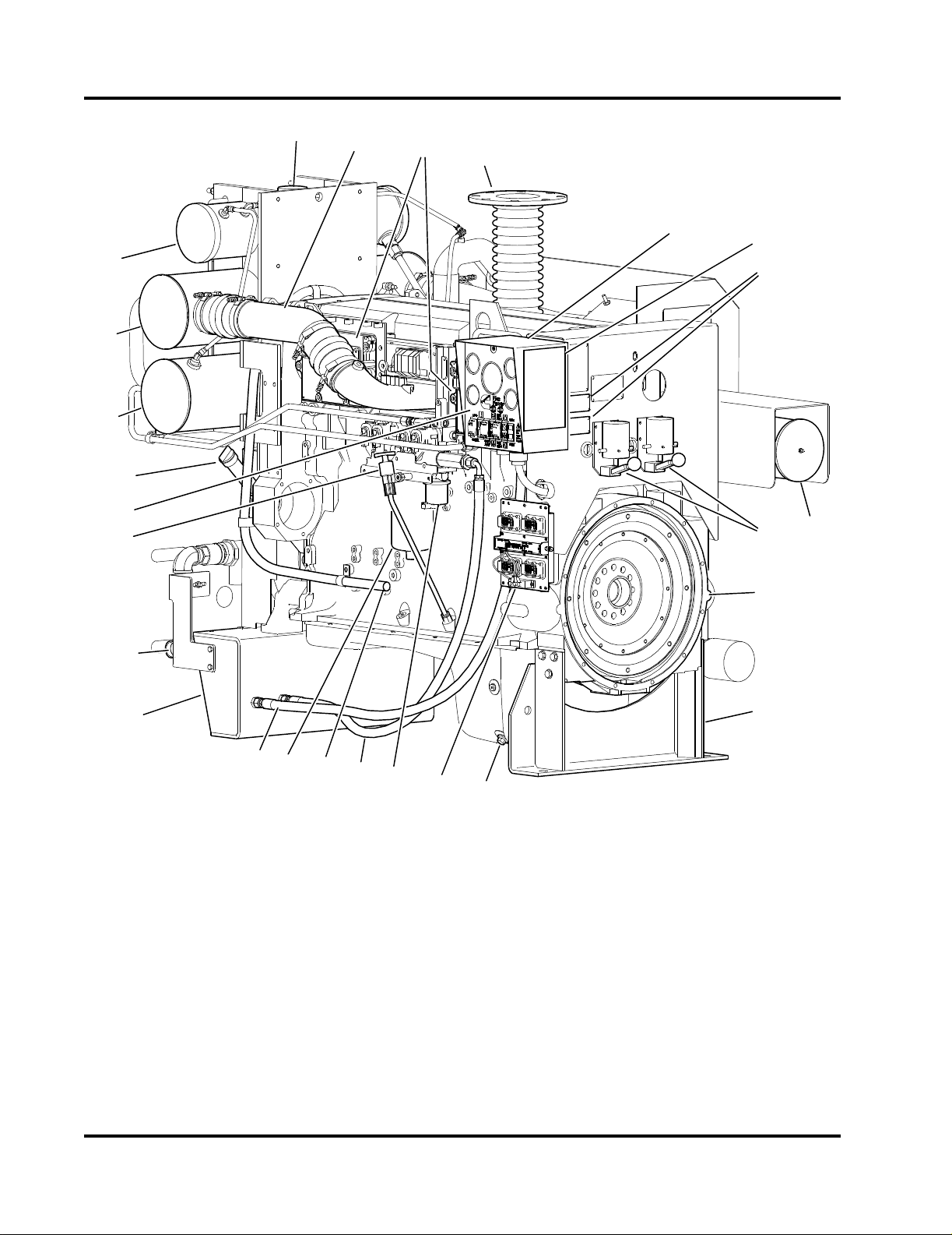
Figure 2-3 Engine Components - Instrument Panel Side . . . . . . . . . . . . . . . . . . . . . . . . . . . . . . . . . . . . . . . 2-2
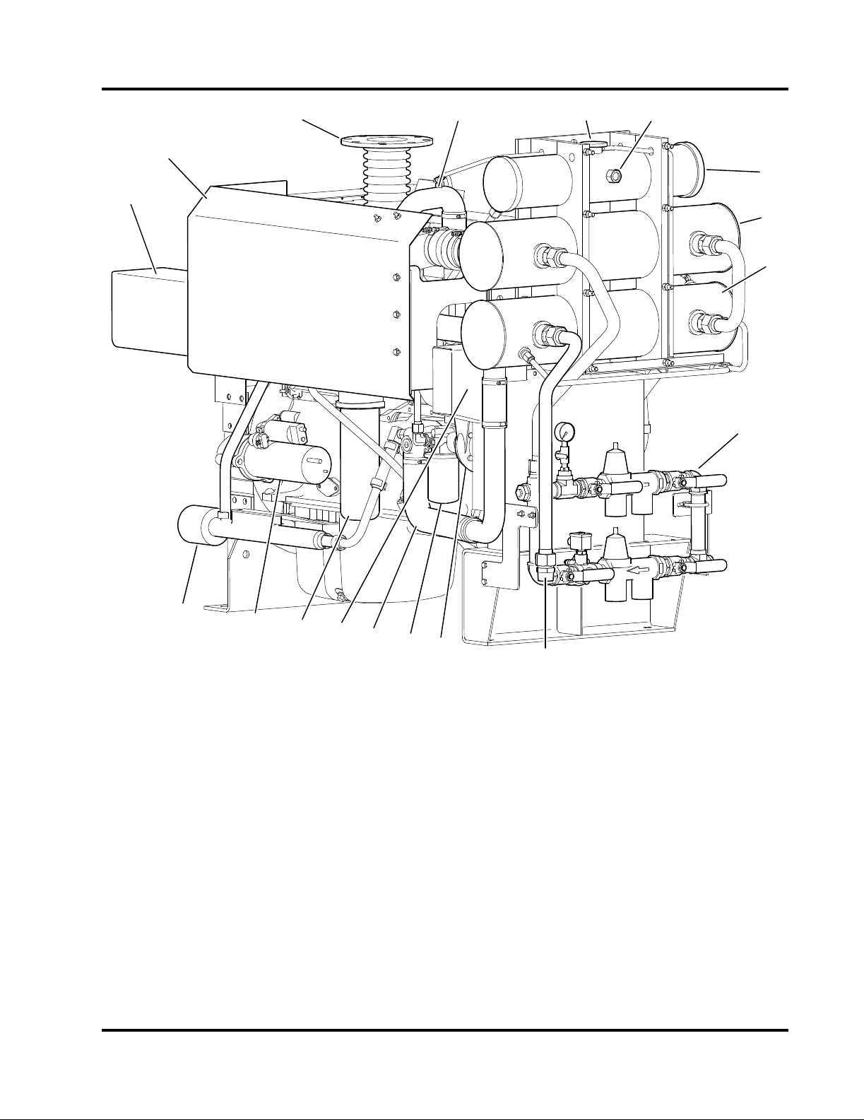
Figure 2-4 Engine Components - Turbocharger Side. . . . . . . . . . . . . . . . . . . . . . . . . . . . . . . . . . . . . . . . . . 2-3
Figure 2-5 Engine Overspeed Control Module . . . . . . . . . . . . . . . . . . . . . . . . . . . . . . . . . . . . . . . . . . . . . . . 2-4
Figure 2-6 Turbocharger and Exhaust Manifold . . . . . . . . . . . . . . . . . . . . . . . . . . . . . . . . . . . . . . . . . . . . . . 2-4
Figure 2-7 Engine Air Intake and Charge Air Cooling Flow Diagram . . . . . . . . . . . . . . . . . . . . . . . . . . . . . . 2-5
Figure 2-8 Engine Cooling System Flow Diagram . . . . . . . . . . . . . . . . . . . . . . . . . . . . . . . . . . . . . . . . . . . . 2-6
Figure 2-9 Fuel System Components. . . . . . . . . . . . . . . . . . . . . . . . . . . . . . . . . . . . . . . . . . . . . . . . . . . . . . 2-8
Figure 2-10 Flow Diagram - Engine Lubricating Oil System (typical) . . . . . . . . . . . . . . . . . . . . . . . . . . . . . . 2-9
Figure 2-11 Flow Diagram - Exhaust System (typical) . . . . . . . . . . . . . . . . . . . . . . . . . . . . . . . . . . . . . . . . 2-10
Figure 2-12 Turbocharger Exhaust Flow Diagram (typical) . . . . . . . . . . . . . . . . . . . . . . . . . . . . . . . . . . . . 2-10
Figure 3-1 Engine Lifting Lugs (Engine Only). . . . . . . . . . . . . . . . . . . . . . . . . . . . . . . . . . . . . . . . . . . . . . . . 3-2
Figure 3-2 Drive Coupling Alignment . . . . . . . . . . . . . . . . . . . . . . . . . . . . . . . . . . . . . . . . . . . . . . . . . . . . . . 3-2
Figure 3-3 Drive Coupling Grease Fittings . . . . . . . . . . . . . . . . . . . . . . . . . . . . . . . . . . . . . . . . . . . . . . . . . . 3-2
Figure 3-4 Fuel Line Inlet and Outlet Hoses. . . . . . . . . . . . . . . . . . . . . . . . . . . . . . . . . . . . . . . . . . . . . . . . . 3-3
Figure 3-5 Engine Fuel Filter . . . . . . . . . . . . . . . . . . . . . . . . . . . . . . . . . . . . . . . . . . . . . . . . . . . . . . . . . . . . 3-3
Figure 3-6 Raw Water Cooling Loop Manifold . . . . . . . . . . . . . . . . . . . . . . . . . . . . . . . . . . . . . . . . . . . . . . . 3-4
Figure 3-7 Cooling Loop Heat Exchangers . . . . . . . . . . . . . . . . . . . . . . . . . . . . . . . . . . . . . . . . . . . . . . . . . 3-5
Figure 3-8 Series Battery Connection - 24 VDC. . . . . . . . . . . . . . . . . . . . . . . . . . . . . . . . . . . . . . . . . . . . . . 3-6
Figure 3-9 Termination Blocks and Wiring Decal . . . . . . . . . . . . . . . . . . . . . . . . . . . . . . . . . . . . . . . . . . . . . 3-7
Figure 3-10 Upper Cooling Hose Clamps. . . . . . . . . . . . . . . . . . . . . . . . . . . . . . . . . . . . . . . . . . . . . . . . . . . 3-8
Figure 3-11 Coolant Circulation System. . . . . . . . . . . . . . . . . . . . . . . . . . . . . . . . . . . . . . . . . . . . . . . . . . . . 3-9
Figure 3-12 Engine Coolant Expansion Tank. . . . . . . . . . . . . . . . . . . . . . . . . . . . . . . . . . . . . . . . . . . . . . . . 3-9
Figure 3-13 Charge Air Cooler Tubing . . . . . . . . . . . . . . . . . . . . . . . . . . . . . . . . . . . . . . . . . . . . . . . . . . . . . 3-9
Figure 3-14 Turbocharger and Charge Air Cooler (CAC) Piping . . . . . . . . . . . . . . . . . . . . . . . . . . . . . . . . 3-10
Figure 3-15 Oil Level Dipstick & Oil Fill Port. . . . . . . . . . . . . . . . . . . . . . . . . . . . . . . . . . . . . . . . . . . . . . . . 3-10
Figure 3-16 Turbocharger Oil Line Location. . . . . . . . . . . . . . . . . . . . . . . . . . . . . . . . . . . . . . . . . . . . . . . . 3-10
Figure 3-17 Turbocharger Turbine Wheel (typical). . . . . . . . . . . . . . . . . . . . . . . . . . . . . . . . . . . . . . . . . . . 3-11
Figure 3-18 Operator Control Panel - Instruments . . . . . . . . . . . . . . . . . . . . . . . . . . . . . . . . . . . . . . . . . . . 3-12
Figure 3-19 Operator Control Panel - Controls. . . . . . . . . . . . . . . . . . . . . . . . . . . . . . . . . . . . . . . . . . . . . . 3-12
Figure 3-20 Manual Starter Contactors . . . . . . . . . . . . . . . . . . . . . . . . . . . . . . . . . . . . . . . . . . . . . . . . . . . 3-12
Figure 4-1 Operator Control Panel - Instruments . . . . . . . . . . . . . . . . . . . . . . . . . . . . . . . . . . . . . . . . . . . . . 4-1
Figure 4-2 Operator Control Panel - Controls. . . . . . . . . . . . . . . . . . . . . . . . . . . . . . . . . . . . . . . . . . . . . . . . 4-2
Figure 4-3 Engine Settings Plates . . . . . . . . . . . . . . . . . . . . . . . . . . . . . . . . . . . . . . . . . . . . . . . . . . . . . . . . 4-3
Figure 4-4 ECM Selector Panel and Switch . . . . . . . . . . . . . . . . . . . . . . . . . . . . . . . . . . . . . . . . . . . . . . . . . 4-4
Figure 4-5 Electronic Control Modules (ECMs) . . . . . . . . . . . . . . . . . . . . . . . . . . . . . . . . . . . . . . . . . . . . . . 4-5
Figure 4-6 Engine Overspeed Control Module . . . . . . . . . . . . . . . . . . . . . . . . . . . . . . . . . . . . . . . . . . . . . . . 4-5
Figure 4-7 Raw Water Flow Control Valves . . . . . . . . . . . . . . . . . . . . . . . . . . . . . . . . . . . . . . . . . . . . . . . . . 4-6
Figure 5-1 Operator Control Panel Switches . . . . . . . . . . . . . . . . . . . . . . . . . . . . . . . . . . . . . . . . . . . . . . . . 5-1
Figure 5-2 ECM Selector Panel and Switch . . . . . . . . . . . . . . . . . . . . . . . . . . . . . . . . . . . . . . . . . . . . . . . . . 5-2
Figure 5-3 Manual Starter Contactors . . . . . . . . . . . . . . . . . . . . . . . . . . . . . . . . . . . . . . . . . . . . . . . . . . . . . 5-3
Figure 5-4 ECM Diagnostic Reader Plug-ins . . . . . . . . . . . . . . . . . . . . . . . . . . . . . . . . . . . . . . . . . . . . . . . . 5-4
Figure 5-5 Control Panel Indicator Lamps . . . . . . . . . . . . . . . . . . . . . . . . . . . . . . . . . . . . . . . . . . . . . . . . . . 5-4
Figure 5-6 Engine Speed Control Panel. . . . . . . . . . . . . . . . . . . . . . . . . . . . . . . . . . . . . . . . . . . . . . . . . . . . 5-5
Fire Power Pump Engine CFP15E
Doc. 9779, Rev. 05-09
TOC-v

Table of Contents
Figure 6-1 Air Filter . . . . . . . . . . . . . . . . . . . . . . . . . . . . . . . . . . . . . . . . . . . . . . . . . . . . . . . . . . . . . . . . . . . 6-4
Figure 6-2 Heat Exchanger Tanks . . . . . . . . . . . . . . . . . . . . . . . . . . . . . . . . . . . . . . . . . . . . . . . . . . . . . . . . 6-5
Figure 6-3 Engine Oil Dipstick . . . . . . . . . . . . . . . . . . . . . . . . . . . . . . . . . . . . . . . . . . . . . . . . . . . . . . . . . . . 6-6
Figure 6-4 Engine Fuel Filter/Water Separator . . . . . . . . . . . . . . . . . . . . . . . . . . . . . . . . . . . . . . . . . . . . . . . 6-6
Figure 6-5 Raw Water Strainers . . . . . . . . . . . . . . . . . . . . . . . . . . . . . . . . . . . . . . . . . . . . . . . . . . . . . . . . . . 6-7
Figure 6-6 24 VDC Series Battery Connection . . . . . . . . . . . . . . . . . . . . . . . . . . . . . . . . . . . . . . . . . . . . . . . 6-8
Figure 6-7 Engine Heater . . . . . . . . . . . . . . . . . . . . . . . . . . . . . . . . . . . . . . . . . . . . . . . . . . . . . . . . . . . . . . . 6-9
Figure 6-8 Air Cleaner Service Indicator. . . . . . . . . . . . . . . . . . . . . . . . . . . . . . . . . . . . . . . . . . . . . . . . . . . 6-10
Figure 6-9 Electrical Control Modules . . . . . . . . . . . . . . . . . . . . . . . . . . . . . . . . . . . . . . . . . . . . . . . . . . . . . 6-10
Figure 6-10 Turbocharger . . . . . . . . . . . . . . . . . . . . . . . . . . . . . . . . . . . . . . . . . . . . . . . . . . . . . . . . . . . . . . 6-11
Figure 6-11 Engine Mounting Bracket . . . . . . . . . . . . . . . . . . . . . . . . . . . . . . . . . . . . . . . . . . . . . . . . . . . . 6-11
Figure 6-12 Fuel Pumps, Filter, Lines and Hoses. . . . . . . . . . . . . . . . . . . . . . . . . . . . . . . . . . . . . . . . . . . . 6-12
Figure 6-13 Oil Pan Drain Plug (right side shown) . . . . . . . . . . . . . . . . . . . . . . . . . . . . . . . . . . . . . . . . . . . 6-12
Figure 6-14 Oil Filter Canister . . . . . . . . . . . . . . . . . . . . . . . . . . . . . . . . . . . . . . . . . . . . . . . . . . . . . . . . . . . 6-13
Figure 6-15 Oil Fill Port and Oil Level Dipstick . . . . . . . . . . . . . . . . . . . . . . . . . . . . . . . . . . . . . . . . . . . . . . 6-13
Figure 6-16 Engine Fuel Filter or Filter/Separator. . . . . . . . . . . . . . . . . . . . . . . . . . . . . . . . . . . . . . . . . . . . 6-14
Figure 6-17 Drive Coupling Grease Fittings . . . . . . . . . . . . . . . . . . . . . . . . . . . . . . . . . . . . . . . . . . . . . . . . 6-14
Figure 6-18 Engine Overspeed Control Module . . . . . . . . . . . . . . . . . . . . . . . . . . . . . . . . . . . . . . . . . . . . . 6-15
Figure 6-19 Coolant Pump Drive Belt . . . . . . . . . . . . . . . . . . . . . . . . . . . . . . . . . . . . . . . . . . . . . . . . . . . . . 6-17
Figure 6-20 Alternator Drive Belt . . . . . . . . . . . . . . . . . . . . . . . . . . . . . . . . . . . . . . . . . . . . . . . . . . . . . . . . 6-18
Figure 6-21 Turbocharger Connections . . . . . . . . . . . . . . . . . . . . . . . . . . . . . . . . . . . . . . . . . . . . . . . . . . . 6-20
Figure 6-22 Turbocharger Turbine Wheel. . . . . . . . . . . . . . . . . . . . . . . . . . . . . . . . . . . . . . . . . . . . . . . . . . 6-20
Figure 6-23 Engine Coolant Drains. . . . . . . . . . . . . . . . . . . . . . . . . . . . . . . . . . . . . . . . . . . . . . . . . . . . . . . 6-21
Figure 6-24 Filter Housing Gasket Mount . . . . . . . . . . . . . . . . . . . . . . . . . . . . . . . . . . . . . . . . . . . . . . . . . . 6-21
Figure 6-25 Thermostat Housing . . . . . . . . . . . . . . . . . . . . . . . . . . . . . . . . . . . . . . . . . . . . . . . . . . . . . . . . 6-23
Figure 6-26 Coolant Pump Drive Belt . . . . . . . . . . . . . . . . . . . . . . . . . . . . . . . . . . . . . . . . . . . . . . . . . . . . . 6-24
Figure 6-27 Alternator Drive Belt . . . . . . . . . . . . . . . . . . . . . . . . . . . . . . . . . . . . . . . . . . . . . . . . . . . . . . . . 6-25
Figure 6-28 Charge Air Cooler (CAC) Heat Exchanger . . . . . . . . . . . . . . . . . . . . . . . . . . . . . . . . . . . . . . . 6-26
TOC-vi
Fire Power Pump Engine CFP15E
Doc. 9779, Rev. 05-09

This manual contains proprietary information to equipment produced by Cummins Fire
Power or Cummins, Inc. and is being supplied solely for the purpose of operating,
maintaining and servicing the fire pump engine purchased from Cummins Fire Power.
© Copyright 2009, Cummins, Inc.

Warranty Information
LIMITED WARRANTY
EXCLUSIVE EXPRESS LIMITED WARRANTY: Cummins Fire Power (CFP), division of Cummins NPower,
LLC expressly warrants to the original end consumer only that, for a period not to exceed the earlier of two (2)
years or 2000 hours of use from the start-up date (or, if the original end consumer fails to register as purchaser
with CFP, six (6) months from CFP shipment date), the diesel fire pump drivers, manufactured and sold by
CFP, shall be free from defects in material and workmanship when used and serviced in accordance with the
Operations and Maintenance manual for the applicable Cummins Fire Pump engine model (the “Exclusive
Warranty”). The Exclusive Warranty is nontransferable and shall immediately terminate and be of no further
force or effect upon the sale, lease, assignment, transfer or other disposition by an original end consumer of a
Cummins Fire Pump engine that contains a diesel fire pump driver covered by this Exclusive Warranty.
Nothing contained herein shall be construed to extend the Exclusive Warranty, and the Exclusive Warranty
shall not be extended, to:
• Maintenance, adjustment, installation or start-up costs;
• Diesel fire pump driver failure due to normal wear, accident, misuse, abuse, neglect, improper installation
or a defect attributable to a Cummins Fire Pump engine;
• Alterations or modifications not authorized in writing by CFP;
• Additional components added to a diesel fire pump driver package subsequent to shipment of the
engine; or
• Starting batteries
• Coolant heaters are covered for 12 months.
DISCLAIMER OF WARRANTIES: Except for the Exclusive Warranty provided above, which is in lieu of all
other express and implied warranties, CFP EXPRESSLY DISCLAIMS ALL EXPRESS AND IMPLIED WARRANTIES, INCLUDING THE IMPLIED WARRANTIES OF MERCHANTABILITY AND FITNESS FOR A PARTICULAR PURPOSE.
LIMITATION AND EXCLUSION OF REMEDIES: All claims under this Exclusive Warranty shall be deemed
waived by the original end consumer if not submitted to CFP or an authorized distributor within thirty (30) days
of initial discovery that a diesel fire pump driver is not conforming to the Express Warranty. The original end
consumer’s remedy under this Exclusive Warranty is limited, in CFP’s reasonable discretion, to repair, replacement or other appropriate adjustment of a nonconforming diesel fire pump driver determined, upon CFP’s
inspection, to have been properly installed, maintained and operated in accordance with the Operations and
Maintenance manual furnished by CFP. IN ANY EVENT, CFP SHALL NOT BE LIABLE FOR INCIDENTAL
OR CONSEQUENTIAL DAMAGES.
The Cummins Industrial Warranty covers the base engine for a period of time not to exceed the earlier of two
(2) years or 2000 hours of operation from the date of delivery and start-up of the engine. Reference bulletin
numbers 3381321 US/Canada & 3381322 Outside US/Canada. Cummins Fire Power components are warranted for a period of time not to exceed the earlier of two (2) years or 2000 hours of operation from the startup date of the fire pump system, and the coverage includes travel time and mileage for the first year of the
Limited Warranty, and repair or replacement of parts and reasonable cost of labor. The Cummins Fire Power
Limited Warranty does not cover failures or damage due to abuse or neglect and including, but not limited to:
shipping damage, improper storage, improper installation, unauthorized modification or lack of maintenance.
Cummins Fire Power is not responsible for incidental or consequential damages.
Section 1 - Safety
WARNING
CAUTION
1.1 Introduction
Cummin’s Fire Power and Engine Manuals should be
considered part of the equipment. Keep the manuals
with the equipment. If the equipment is traded or sold,
give the manuals to the new owner.
All personnel responsible for operation and maintenance of the equipment should read and thoroughly
understand this manual.
1.2 Advisory and Cautionary Statements
Advisory and Cautionary Statements are used
throughout this manual to call attention to special
information, correct operating procedures and to
safety precautions.
NOTE: A general advisory statement relating to
equipment operation and maintenance procedures
IMPORTANT: A specific advisory statement intended
to prevent damage to the equipment or associated
components.
Cautionary Statements consist of two levels:
Warning: Perform a walk around inspection and alert
all area personnel that the equipment will be starting
before manual operation.
Warning: Do not operate faulty or damaged equipment. Ensure that all hoses, pipe connections,
clamps and guards are in place and securely fastened. Electrical components should be kept in good
working condition and repaired immediately by qualified personnel.
Warning: After performing maintenance, remove all
tools and foreign materials, reinstall and securely
fasten ALL guards, covers and protective devices.
Warning: Exposed in-running belt nips can cause
severe personal injury or dismemberment. Ensure
that guards are in place and securely fastened before
operation.
Warning: Rotating drive shafts can lacerate, dismember or cause strangulation. Keep hands, body
parts, long hair, or loose-fitting clothing clear at all
times.
Warning: Never attempt to manually clean a
machine while it is operating or in standby mode.
Indicates the presence of a hazard which CAN
cause severe personal injury.
Indicates the presence of a hazard which CAN
cause personal injury, or cause equipment
damage.
1.3 Safety Precautions
Warning: Read and understand all of the safety pre-
cautions and warnings before performing any repair.
This manual contains the general safety precautions
that must be followed to provide personal safety.
When they apply, special safety precautions are
included with operating procedures.
Fire Power Pump Engine CFP15E
Doc. 9779, Rev. 05-09
Warning: Never open ports on tanks or piping while
the engine is operating. Contact with pressurized
agents can cause severe personal injury.
Warning: Relieve all pressure in the air, oil, and the
cooling systems before any lines, fittings, or related
items are removed or disconnected.
Caution: Engine fuel is flammable when in contact
with electrical spark or flame sources. Remove all
sources of spark or flame from the work area.
Caution: Always use the same fastener part number
(or equivalent) when replacing fasteners.
Caution: Some state and federal agencies in the
USA have determined that used engine oil can be
carcinogenic and can cause reproductive toxicity.
Dispose of waste oil in accordance with applicable
requirements.
1-1

1-2
Fire Power Pump Engine CFP15E
Doc. 9779, Rev. 05-09
Section 2 - Description
6
3
12
4
5
CFP-070
2
1
3
567
4
8
9
10
11
12
CFP-071
2.1 Introduction
This manual contains information for the correct operation and maintenance of a Cummins Fire Pump
Engine. Read and follow all safety instructions. Refer
to the General Safety Instructions in Section 1 -
Safety.
Keep this manual with the equipment. If the equipment is traded or sold, give the manual to the new
owner.
Cummins Fire Power, Cummins NPower and Cummins, Inc. reserve the right to make changes at any
time without obligation. If any differences are found
between an engine and the information in this
manual, contact the local Cummins Authorized
Repair Location.
The latest technology and the highest quality components were used to produce this engine. When
replacement parts are needed, we recommend using
only genuine Cummins or ReCon® exchange parts.
2.2 Fire Pump Engines
Cummins complete line of fire pump engines have
been approved as packaged units (engine and all
accessories) by Factory Mutual Approvals and listed
by Underwriter’s Laboratories, Inc. and Underwriter’s
Laboratories of Canada.
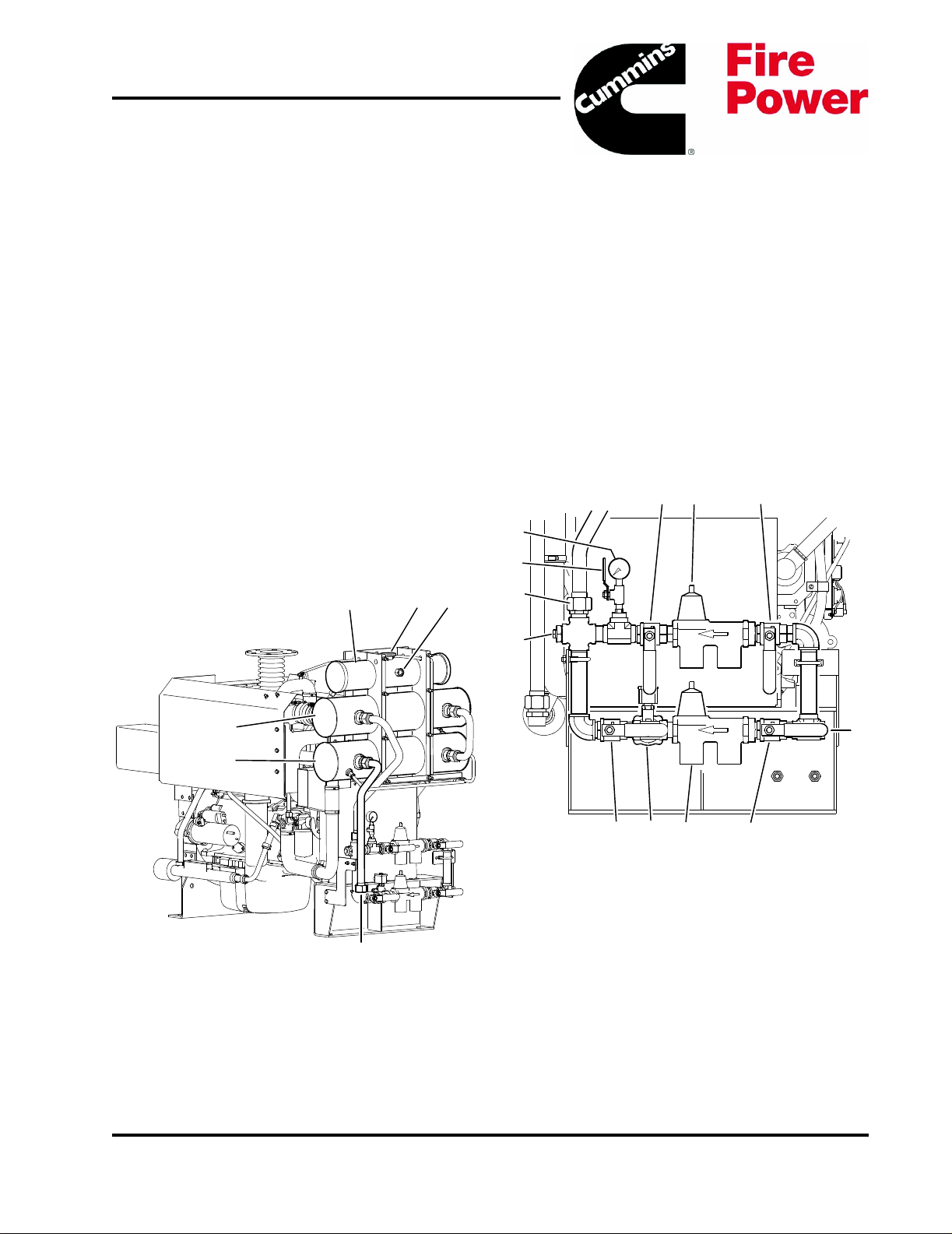
1. Coolant Expansion Tank
2. Coolant Fill Cap
3. Expansion Tank Level Sight Gauge
4. Charge Air Cooler (CAC) Heat Exchanger
5. Coolant/Fuel Heat Exchanger
6. Heat Exchanger Discharge
Figure 2-1 Heat Exchanger Tanks
Fire Power Pump Engine CFP15E
Doc. 9779, Rev. 05-09
1. Bypass Water Outlet Valve
2. Bypass Pressure Regulator/Strainer
3. Bypass Water Inlet Valve
4. 1-1/4” NPT Raw Water Inlet
5. Normal Water Inlet Valve
6. Normal Pressure Regulator/Strainer
7. Normal Water Solenoid Valve
8. Normal Water Outlet Valve
9. Raw Water Drain Plug
10. Pipe To Heat Exchanger
11. Pressure Gauge Isolation Valve
12. Water Supply Pressure Gauge
Figure 2-2 Raw Water Cooling Loop Manifold
2-1
2
1
3
4
5
6
7
8
9
10
11
12
13
14
15
16
17
11
19
20
21
22
23
24
25
18
CFP-072
1. Coolant Pressure/Fill Cap
2. Charge Air Cooler Pipe
3. Electronic Control Modules (ECMs)
4. Exhaust Flex Connection
5. Terminal Box (customer connection inside)
6. Manual Start Instruction Decal
7. Engine Speed Settings Plate
8. Air Cleaner
9. A/B Battery Starter Contactors
10. Flywheel Housing
11. Engine Supports
12. Oil Pan Drain
13. ECM Selector Panel and Switch
Figure 2-3 Engine Components - Instrument Panel Side
14. Fuel Lift Pump
15. Fuel Supply Line
16. Engine Breather Hose
17. Fuel Filter
18. Fuel Return Line
19. 1-1/4” NPT Raw Water Inlet
20. Oil Level Dip Stick
21. Operator’s Control Panel
22. Oil Fill Port
23. Coolant/Fuel Heat Exchanger
24. Charge Air Cooler (CAC) Heat Exchanger
25. Coolant Expansion Tank
2-2
Fire Power Pump Engine CFP15E
Doc. 9779, Rev. 05-09
4
6
5
12
13
14
16
15
2
1
3
7
8
9
10
11
17
18
CFP-073
1. Air Cleaner Assembly
2. Manifold Heat Shield
3. Exhaust Flex Connection
4. Upper Coolant Hose
5. Coolant Pressure/Fill Cap
6. Expansion Tank Level Sight Gauge
7. Coolant Expansion Tank
8. Charge Air Cooler (CAC) Heat Exchanger
9. Coolant/Fuel Heat Exchanger
10. Raw Water Manifold
11. 1-1/2” NPT Raw Water Outlet
12. Coolant Pump
13. Coolant Filter
14. Lower Coolant Hose
15. Alternator (under belt guard)
16. Engine Oil Filter
17. Starter Motor
18. Engine Heater
Figure 2-4 Engine Components - Turbocharger Side
Models CFP15E-F10 through F40 meet Tier 3 emission levels, while models CFP15E-F50 through F70
meet Tier 2 emission levels. This turbocharged
engine requires charge air cooling (CAC) and fuel
cooling.
2.3 Operator Control Panel
The engine control panel is mounted on the flywheel
end on the left (fuel pump) side of the engine. Refer
to Section 4 - Controls for additional information.
No deviations are permitted without prior written
approval. These engines are to be used only for fire
protection applications. Refer to Figure 2-1, Figure
2-2, Figure 2-3 and Figure 2-4.
Fire Power Pump Engine CFP15E
The operator control panel contains controls for starting, monitoring engine performance and controlling
fire pump engine operation.
Doc. 9779, Rev. 05-09
2-3
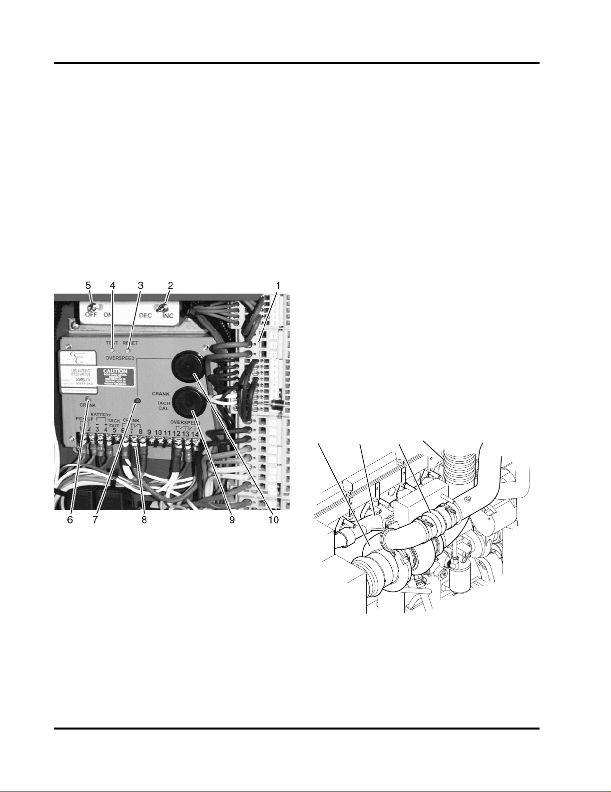
2.3.1 Overspeed Switche
CFP-040
21 43
CFP-142
Each engine is equipped with an electronic overspeed module which activates the fuel pump solenoid
valve and ECM ignition to shut off the engine when
the RPM exceeds a preset limit. The overspeed
switch senses engine speed during the start cycle
and stops the starter motor cranking cycle. Refer to
Figure 2-5.
2.3.2 Operating Speed
All Cummins fire pump engines are shipped from the
factory adjusted to the requested operating speed
(RPM). Final operating speed adjustment must be
made during the in-service inspection to obtain the
required operating speed specified by the pump manufacturer.
2.4 Fire Pump Controller
Fire pump controller is not supplied by Cummins Fire
Power, or Cummins, Inc. The fire pump controller
starts the engine automatically when a remote fire
demand signal is initiated and automatically shuts
down the engine when the fire demand signal is discontinued.
The engine may be started locally in the MANUAL
Mode and shut down using the operator control panel
AUTO/MANUAL Mode Switch by returning the switch
to automatic mode.
NOTE: Pressure recorders are available to provide a
permanent record of water pressure fluctuations and
engine starts. Sequential starting is available for
multiple-pump installations to prevent all pumps from
starting simultaneously.
2.5 Air Intake System
The Air Intake System supplies combustion air to the
fire pump engine cylinders. The air filter prevents particulate matter from entering the air intake. Combustion air drawn into the system by the turbocharger is
directed through the charge air cooler (CAC) heat
exchanger for cooling before entering the intake manifold where the charge air is mixed with fuel. Refer to
Figure 2-6 and Figure 2-7.
1. Spring Clamp Terminal Blocks
2. Speed Increase/Decrease Toggle Switch
3. RESET Button
4. TEST Button
5. Diagnostic ON/OFF Toggle Switch
6. CRANK Termination or Run Signal Indicator
LED (factory use only)
7. Overspeed Indicator LED
8. Pre-wired Terminals
9. Crank Terminate Potentiometer Cover
10. Overspeed Potentiometer Cover
Figure 2-5 Engine Overspeed Control Module
2-4
Fire Power Pump Engine CFP15E
Doc. 9779, Rev. 05-09
1. Turbocharger
2. Exhaust Manifold
3. Turbo Connection to Charge Air Cooler
4. Exhaust Flex Connection
Figure 2-6 Turbocharger and Exhaust Manifold
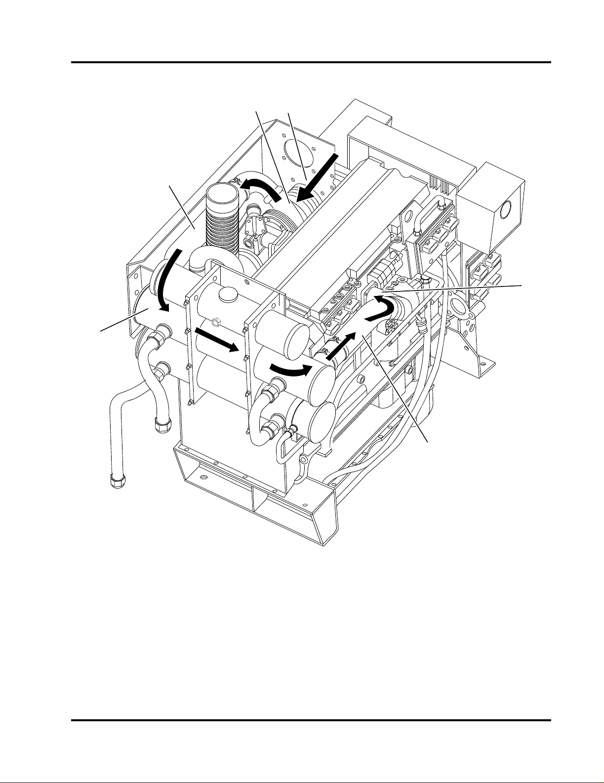
6
1
2
3
4
5
CFP-062
1. Filtered Intake Air from Air Cleaner
2. Turbocharger
3. Air Hose To Charge Air Cooler
Figure 2-7 Engine Air Intake and Charge Air Cooling Flow Diagram
2.6 Raw Water Cooling System
The fire pump raw water supply provides cooling
water for the engine heat exchanger system. A waterto-air Charge-Air-Cooler (CAC) Heat Exchanger
reduces the combustion air temperature at the intake
Fire Power Pump Engine CFP15E
Doc. 9779, Rev. 05-09
4. Charge Air Cooler (CAC) Heat Exchanger
5. Charge Air Cooler Pipe
6. Combustion Air Intake Manifold
manifold. A low charge air temperature (requirement
of 60° C (140° F) (with 25° C (77° F) ambient) meets
emission levels while improving engine performance
and efficiency.
2-5
CFP-063
20 1819
14 15
17
4
5
6
7
97
10
11
78 9 7
12
3
12
16
13
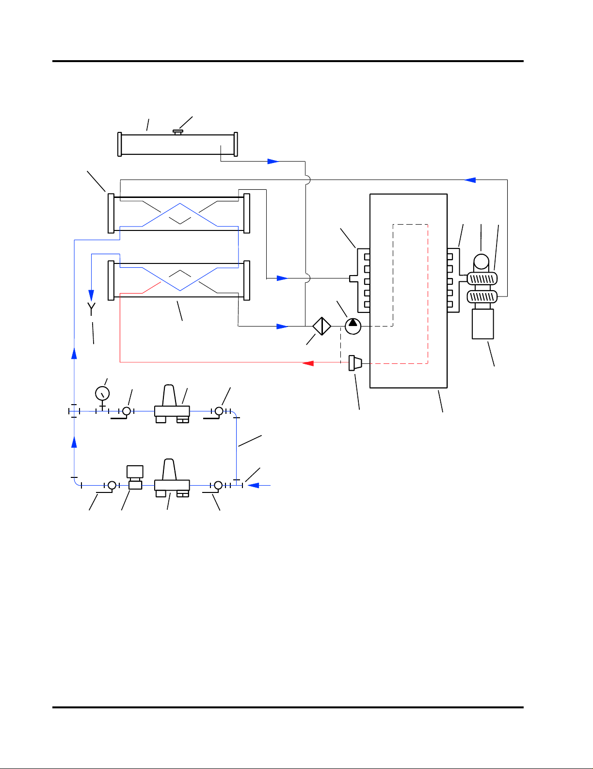
1. Coolant Fill Cap
2. Coolant Expansion Tank
3. Charge Air Cooler (CAC) Heat Exchanger
4. Coolant/Fuel Heat Exchanger
5. Raw Water Drain Line
6. Raw Water Pressure Gauge
7. Manual Shut-off Valve
8. Raw Water Solenoid Valve
9. Raw Water Pressure Regulator/Strainer
10. Bypass Piping
Figure 2-8 Engine Cooling System Flow Diagram
11. Raw Water Inlet Pipe
12. Coolant Pump
13. Coolant Filter
14. 85° C (180° F) Thermostat
15. Engine Block
16. Combustion Air Intake Manifold
17. Air Filter
18. Turbocharger
19. Exhaust Flex Connection
20. Exhaust Manifold
2-6
Fire Power Pump Engine CFP15E
Doc. 9779, Rev. 05-09

Water entering the cooling system through the 1-1/4”
NPT raw water inlet, first circulates through the
charge air cooler (CAC) heat exchanger, cooling the
compressed air from the turbocharger outlet ducting.
The cooled combustion air exits the CAC outlet duct
to the engine air intake manifold. Refer to Figure 2-1,
Figure 2-2 and Figure 2-7.
NOTE: The raw water supply must be immediately
available when the engine is started.
The raw water from the CAC heat exchanger then
enters the Coolant/Fuel Heat Exchanger. The raw
water exits the Coolant/Fuel Cooler Heat Exchanger
through the 1-1/2” NPT drain line. Refer to Figure 2-7.
fill cap must meet the minimum pressure of 10 kPa
(15 psi).
The engine coolant system contains a mixture of at
least 50% anti-freeze and 50% water. The coolant
level should be maintained in or just below the
coolant expansion tank level sight gauge.
CAUTION
Continuous operation with low coolant temperature (below 70° C (158° F)) or high coolant temperature (above 107° C (225° F)) can damage the
engine. Verify raw water coolant pressure and
flow.
IMPORTANT: If the piping will be supplied by the
customer, provide raw water supply piping and components equivalent to components supplied by
Cummins Fire Power and as shown in Assembly Diagram, Raw Water Piping. Refer to National Fire Protection Association NFPA20 Chapter 11 for US
installation requirements. When choosing components for the raw water supply and bypass, ensure
that the internal cross sectional area of the component is at least as large as the recommended pipe
size.
When the raw water piping is installed, adjust both
pressure regulator set points before operating the
pump.
1. The upper line is the bypass line. The bypass
line outlet valve should be closed.
2. The lower line with the solenoid valve is the
normal inlet line. The pressure gauge isolation
valve must be open. The normal raw water inlet
line valve should be open.
IMPORTANT: Monitor the oil pressure and coolant
temperature gauges frequently. Refer to Lubricating
Oil System Specifications or Cooling System Specifications in the Engine Data Sheets for recommended
operating pressures and temperatures. Shut off the
engine if any pressure or temperature does not meet
the specifications.
Maximum engine coolant temperature should not
exceed 107° C (225° F). The coolant expansion tank/
2.7 Fuel Cooling System
A combination coolant/fuel cooling heat exchanger
maintains fuel temperature to meet the maximum
allowable fuel inlet temperature (71° C (160° F)). Performance of the fuel cooling system is critical to
engine durability, performance and emissions compliance.
2.7.1 Fuel Supply and Drain Location
The fuel inlet and drain connections are located at the
front of the unit below the raw water manifold assembly. The fuel inlet line runs from the connection fitting
directly to a Lift Pump and Fleetguard® 25 micron
fuel filter instead of to an ECM cooling plate. Refer to
Figure 2-9.
2.8 High Pressure Injector (HPI) Fuel System
The fire pump engine is equipped with an electronic
fuel system that delivers precise fuel quantities with
precise injection timing at high injection pressures.
The system consists of six (6) high-pressure unit
injectors and an Integrated Fuel System Module
(IFSM). The IFSM provides individual cylinder control
fuel metering and injection timing and controls the
fuel supply pump and regulator pressure using
various system monitoring sensors. The system is
controlled by CM570 Engine Control Modules
(ECMs) for fueling and timing based on temperature,
altitude, boost pressure, and throttle position. Refer
to Figure 2-9.
Fire Power Pump Engine CFP15E
Doc. 9779, Rev. 05-09
2-7
2
1
34 5 6
7
8910111213
CFP-074
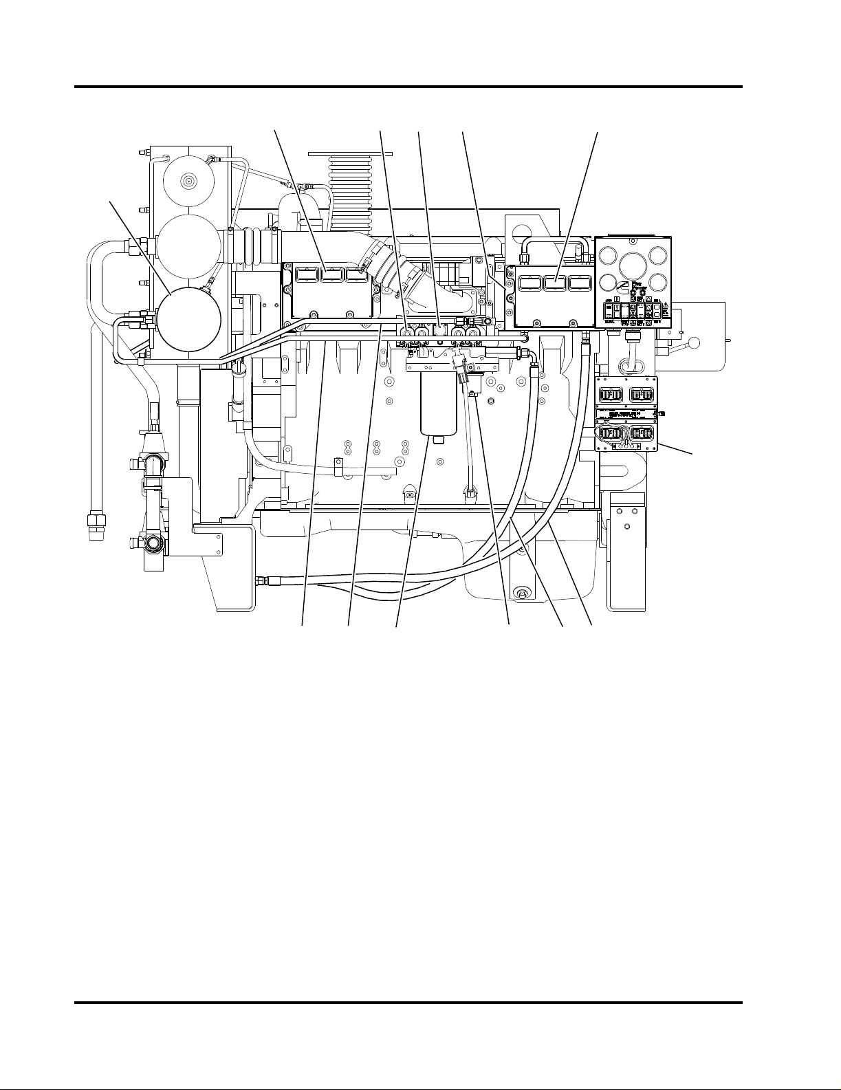
1. Coolant/Fuel Cooling Heat Exchanger
2. ECM Module A
3. Integrated Fuel System Module (IFSM)
4. Fuel Pump
5. ECM Cooling Plate
6. ECM Module B
7. ECM Selector Panel and Switch
Figure 2-9 Fuel System Components
With the HPI fuel system, fuel priming is required for
conditions such as: initial start-up, running out of fuel
and maintenance of fuel system components (i.e.,
filter change). A 24 VDC fuel lift pump is standard.
2-8
Fire Power Pump Engine CFP15E
Doc. 9779, Rev. 05-09
8. Fuel Return Line
9. Fuel Supply Line
10. Fuel Lift Pump
11. Fuel Filter or Filter/Separator
12. Fuel Cooling Line To Heat Exchanger
13. Fuel Cooling Line From Heat Exchanger
NOTE: The system will prime a totally dry fuel system
in 120 seconds or less. Applications with remote fuel
tank requires a fuel lift pump (supplied). Lift pump run
time is limited to two minutes.
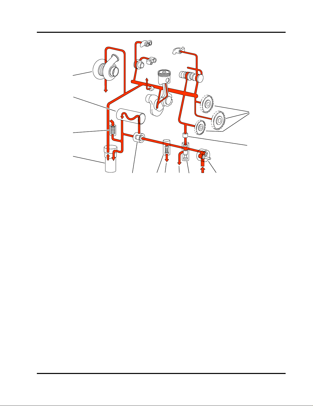
1. Oil Pump
1
2
3
4
7
5
8
9
10
12
6
11
CFP-010
2. Pressure Regulator Valve
3. Oil Return To Pan
4. High Pressure Relief Valve
5. Oil Return To Pan
6. Oil Thermostat
Figure 2-10 Flow Diagram - Engine Lubricating Oil System (typical)
7. Oil Cooler
8. Combination Oil Filter
9. Filter Bypass Gears
10. Idler Gears
11. Viscosity Sensor
12. Turbocharger
2.9 Engine Oil System
The Engine Oil System lubricates moving internal
engine parts (pistons, piston arms, valves, cam
shafts, drive shafts and bearings). The oil pump circulates oil from the oil pan, through the oil filter and into
engine areas where friction may develop. Refer to
Figure 2-10.
Typically engine oil has been added during manufacture and testing procedures, however, shipping
restrictions can affect whether the oil is maintained in
the engine or drained for shipment.
Fire Power Pump Engine CFP15E
Doc. 9779, Rev. 05-09
Check the oil level at the dipstick. Add oil as necessary to bring the oil level to the H (high) mark on the
dipstick.
2.10 Exhaust System
The exhaust system removes engine exhaust from
the cylinders after the combustion process. The
exhaust discharges from the exhaust manifold,
passes through (drives) the turbocharger, and exits
through the exhaust flex-pipe. Refer to Figure 2-11,
and Figure 2-12.
2-9
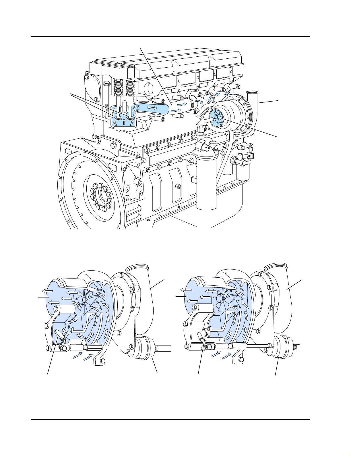
1. Exhaust Valve Ports
1
2
3
4
CFP-008
1
2
3
4
5
1
3
2
CFP-011
2. Exhaust Manifold
3. Combustion Air To Charge Air Cooler
4. Turbocharger Turbine
Figure 2-11 Flow Diagram - Exhaust System (typical)
1. Wastegate Actuator Cylinder
2. Exhaust Flow to Flex Pipe
4. Wastegate OPEN
5. Wastegate CLOSED
3. Combustion Air To Charge Air Cooler
Figure 2-12 Turbocharger Exhaust Flow Diagram (typical)
2-10
Fire Power Pump Engine CFP15E
Doc. 9779, Rev. 05-09

Section 3 - Installation
3.1 Receiving and Handling Information
Cummins Fire Power Pump Engines are pre-assembled and tested before shipment. Parts not shipped
attached to the engine are sometimes shipped individually. The equipment was thoroughly inspected
and prepared for shipping before it was turned over to
the carrier.
1. Carefully remove the components from the shipping container. Remove crating, shipping tape,
braces and tie-downs.
2. Inspect the equipment for damage that may
have occurred in shipping.
3. Check each item carefully against the shipping
manifest or bill of lading.
3.1.1 Damage During Shipping
File a Claim For Damages with the carrier, if your
equipment was received damaged or not received at
all. Notify Cummins Fire Power, or Cummins Inc. as
soon as possible to determine if a replacement item
or repair is required.
3.1.2 Claim Filing Procedure
The following information is required if a claim is filed:
should be used when returning the engine to operation after overhaul or major maintenance.
The site should be clean and relatively level. Clear
the proposed equipment area of overhanging
obstructions and obstacles protruding from the floor.
Raw water piping should be installed by trained technicians, familiar with local, state and federal codes
and regulations, per the equipment layouts supplied
by Cummins Fire Power, or Cummins Inc.
3.2.1 Site Considerations
Refer to the general fire pump and engine layout
drawings for installation dimensions supplied with this
manual.
CAUTION
Avoid installation in a dusty or dirty environment.
Provide adequate physical protection from other
physical damage as may be present in the specific location.
Refer to National Fire Protection Association NFPA
20, Chapter 11 for US installation and applicable local
code requirements.
1. A Claim Statement describing the damaged or
lost merchandise and how the claim was determined.
2. A Bill of Lading or Freight Bill is required as proof
of who transported the freight.
3. A noted Freight Bill or Inspection Report Copy,
as evidence of loss or damage.
4. Invoice Copy or other documents establishing
the cost to you of the freight lost or damaged, or
an Invoice for Repairs.
3.2 Site Preparation
This section provides instructions for the initial installation, adjustment, and testing of the Cummins Fire
Pump Engine. Appropriate portions of this section
Fire Power Pump Engine CFP15E
Doc. 9779, Rev. 05-09
1. Lay out a designated center line on the site floor.
Find the center line of the engine drive shaft. Lay
out a center line on the cross frame members.
IMPORTANT: Ensure that the lifting device or forklift
is capable of handling the package weight and size
requirements.
2. If the engine is lifted separately, use the lifting
hooks (supplied with the engine) and a spreader
bar to position the engine. Refer to Figure 3-1.
If the engine is assembled with the drive line,
pump and mounting base, use the lifting points
provided on the mounting base or lift the entire
skid using an approved fork lift. Refer to the layout drawings supplied with this manual for lifting
points.
3-1
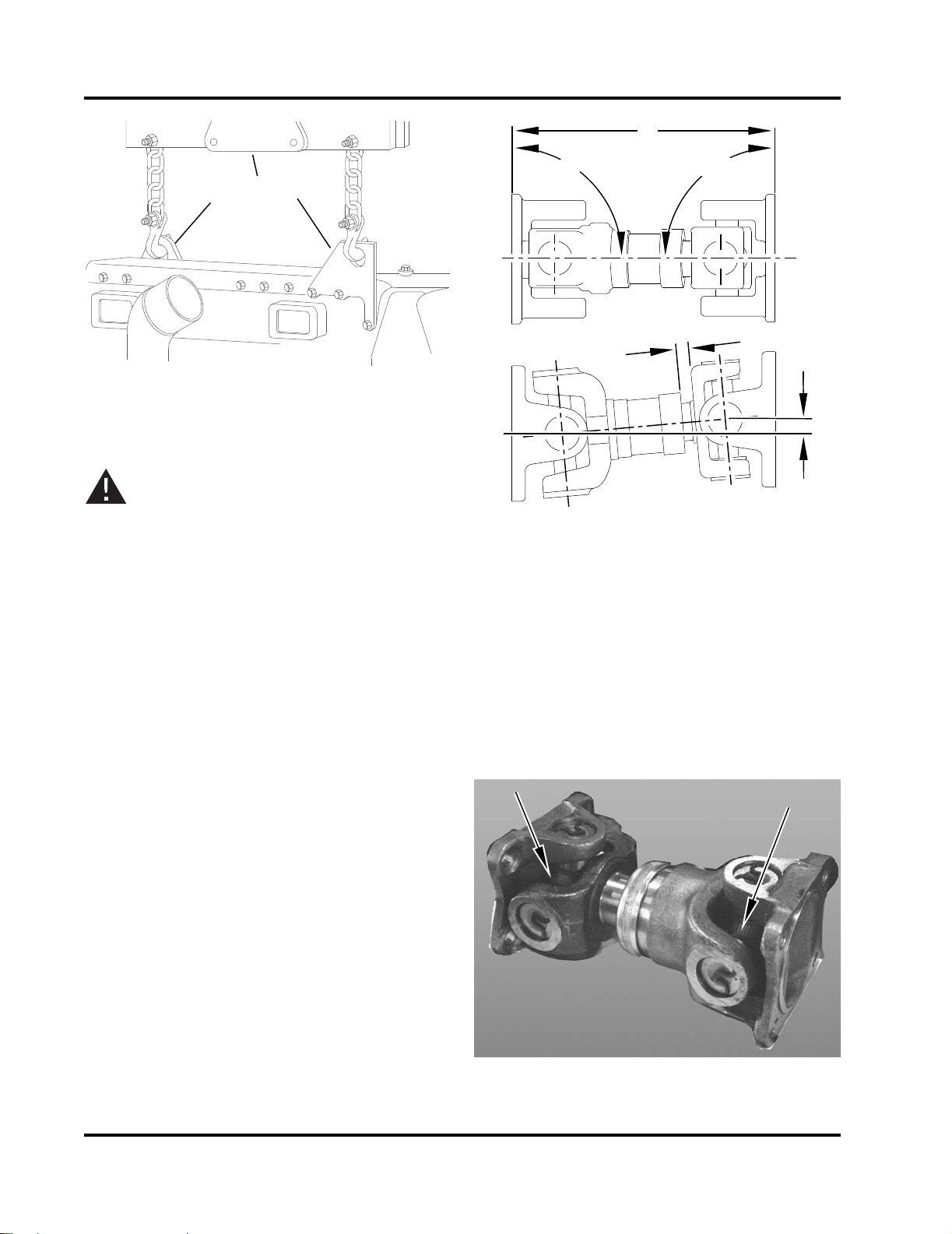
1. Lifting Lug
1
1
2
CFP-064
2
4
1
3
90
°
90
°
TOP
SIDE
CFP-013
CFP-015
2. Lifting Spreader Bar
Figure 3-1 Engine Lifting Lugs (Engine Only)
CAUTION
Ensure that the lifting device is capable of safely
lifting the weight of the engine or the combined
weight of the assembled pump base, drive line
and pump. Refer to the Bill of Lading for combined shipping weights.
3. Position the engine as required for the interface
with the fire pump, water piping, fuel piping,
exhaust and air system connections.
1. Planes Must Be Parallel
2. Align Both Mounting Center lines to
± .03”
3. Distance to Equal Half of Total Travel
4. .25”: +0, -.25” Offset
Figure 3-2 Drive Coupling Alignment
5. Check that the fire pump is properly installed per
the pump manufacturer’s specifications.
4. Position the engine center line to align the
engine drive shaft with the fire pump drive.
Ensure that the engine and pump are correctly
aligned.
a. Ensure engine position is centered on frame
side to side within ± .03 inch, by measuring
outside of frame side to engine support leg
mounting pad. (Compare two front engine
supports and two back engine supports).
b. Align engine center line to pump center line
within ± .03 inch. Refer to Figure 3-2.
c. The pump center line to the engine crank
center line (in vertical plane) is to be .25 inch:
+0, -.25 inch offset.
d. Drive shaft mounting flanges must be
parallel.
3-2
Fire Power Pump Engine CFP15E
6. Connect the exhaust piping to a safe location,
away from building air intake sources (air conditioners, windows, fresh air intake pipes, etc.).
Figure 3-3 Drive Coupling Grease Fittings
Doc. 9779, Rev. 05-09
7. Check that the alternator and coolant pump drive
3
2
1
CFP-075
1
34
5
2
CFP-076
belts are properly installed.
8. Check that all hoses and tubes are properly
installed and all clamps secure.
9. Lubricate grease fittings on the drive shaft universal joint. Refer to Figure 3-3.
a. Wipe the grease fittings and grease gun noz-
zle with a clean cloth.
b. Add grease to the universal joint grease fit-
tings.
c. Wipe excess grease from the grease fittings.
NOTE: Cummins Fire Power, or Cummins Inc. recommends using a good quality semi-synthetic,
molybdenum-fortified NLGI #2 lithium complex
grease which protects from -54° to 400° F such as
Valvoline Durablend®.
NOTE: Some lubrication loss may occur during transport and storage. It is recommended that the drive
shaft be re-lubricated upon installation.
3.3 Fuel Supply Installation
1. Install an elevated no. 2 diesel fuel tank or other
fuel supply arrangement which is compatible
with ASTM no. 2 diesel fuel specifications.
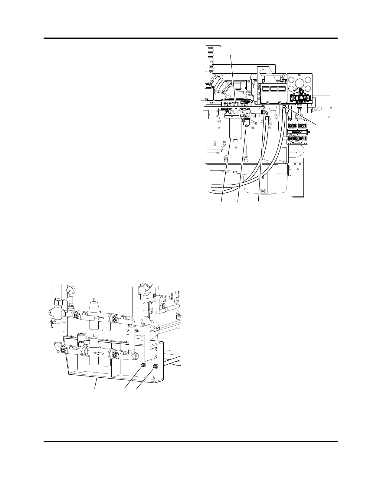
1. Fuel Injection Pump
2. Fuel Return Connection
3. Fuel Supply Connection
4. Fuel Lift Pump
5. Fuel Filter or Filter/Separator
Figure 3-5 Engine Fuel Filter
NOTE: The fuel supply line at the fuel tank must be
higher than the fuel intake port on the engine fuel
filter. Ensure that the fuel system is installed in a safe
and effective manner.
2. Size the fuel tank for the maximum expected fullload engine operation period with the initial fuel
level at the minimum level for refueling.
3. Install a 3/4“ NPT (minimum) fuel return line.
Route this line to the bottom of the fuel tank in
order to minimize the return head. Refer to
Figure 3-4.
4. Install a 3/4” NPT (minimum) fuel supply line to
the fire pump engine.
1. Engine Base Frame
2. 3/4” Fuel Inlet Hose
3. 3/4” Fuel Outlet Hose
NOTE: DO NOT use copper or galvanized pipe for
the fuel return or supply lines.
3.3.1 Fuel System Preparation
The fire pump engine fuel system has been primed
Figure 3-4 Fuel Line Inlet and Outlet Hoses
Fire Power Pump Engine CFP15E
during manufacturing and test procedures. The
3-3
Doc. 9779, Rev. 05-09
engine is equipped with an electric primer pump
WARNING
2
1
3
567
4
8
9
10
11
12
CFP-071
which primes the fuel filter or filter/separator and high
pressure fuel pump when the engine is cranked.
Refer to Figure 3-5.
IMPORTANT: The raw water supply must be immediately available when the engine is started. Ensure
that the supply line valves are in the OPEN position.
A Water Separator must be integrated into the fuel
delivery system of the fire pump engine. A Fuel Filter/
Water Separator may be installed directly on the unit
in the primary fuel filter location, or a separate filter/
separator may be installed in the fuel delivery system
near the fire pump engine assembly.
1. Ensure that the filter/separator is free of water by
opening the fuel filter/water separator drain at
the bottom of the filter. Refer to 6.3.5 Fuel Sys-
tem Inspections for additional information.
2. Drain the fuel into a container until no water is
present. Dispose of the contaminated fuel in
accordance with local environmental regulations.
CAUTION
Due to the precise tolerances of diesel injection
systems, it is extremely important that the fuel be
kept clean and free of dirt or water. Dirt or water
in the system can cause severe damage to both
the fuel pump and the fuel injectors.
CAUTION
When the raw water piping is installed, adjust
both pressure regulator set points before operating the pump. Damage to the heat exchanger may
occur from improperly regulated raw water
supply pressure.
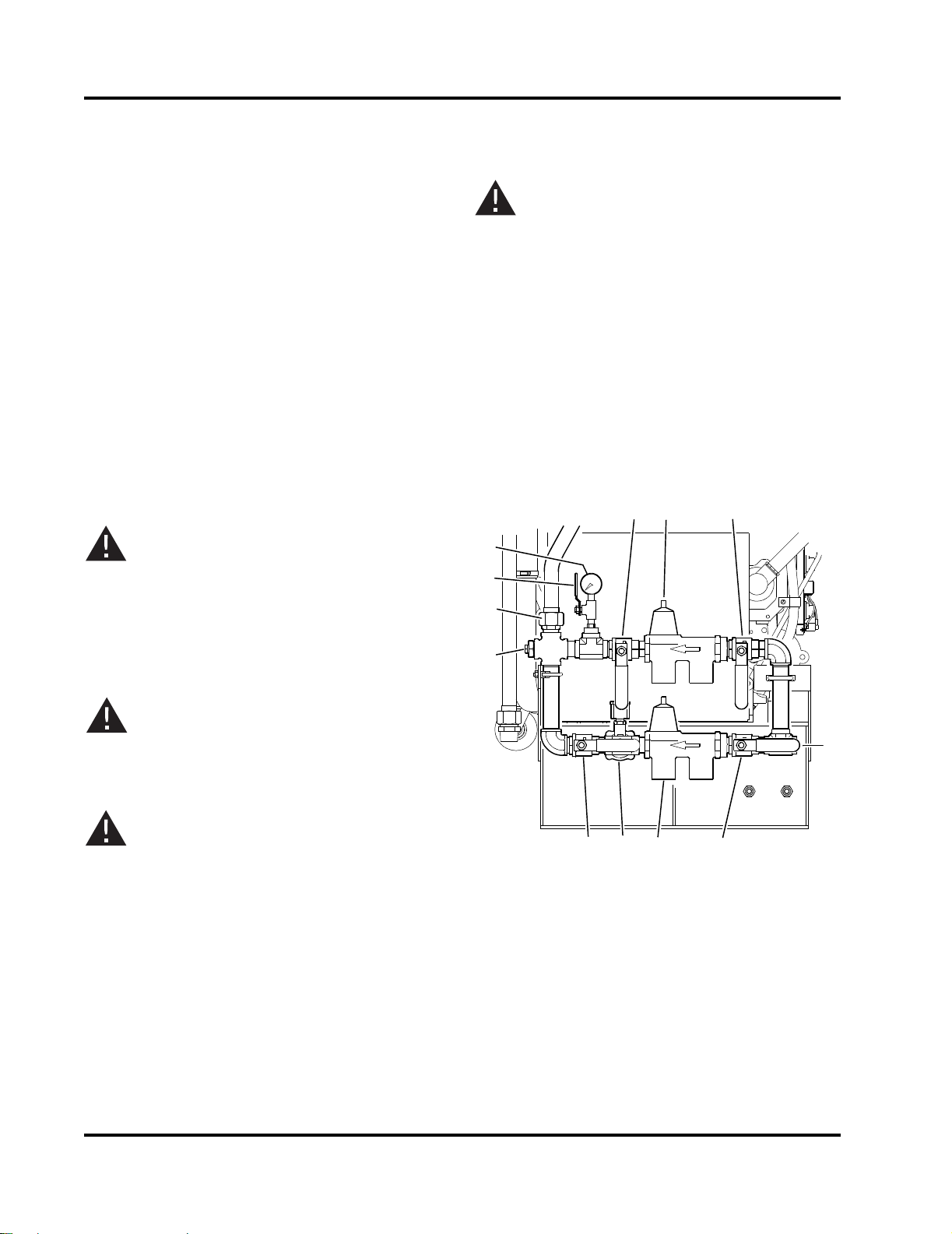
3.4.1 Install Raw Water Piping NOTE: The velocity of the raw water should be as
great as possible without exceeding the maximum
allowable pressure shown in the appropriate engine
data sheet.
1. Provide 1-1/2” NPT raw water drain line at the
outlet of the heat exchanger. Refer to Figure 3-6.
3.3.2 Fuel Recommendations
Do not mix gasoline, alcohol, gasohol, ethanol or
methanol with diesel fuel. This mixture will cause
severe engine damage or explosion.
CAUTION
Use ONLY no. 2 diesel (ASTM no. 2D) fuel. Any
adjustment to compensate for reduced performance with a fuel system using alternate fuel is
not warrantable.
3.4 Raw Water Supply Installation
Raw water circulated through the system cools the
charge air cooler (CAC) heat exchanger, the coolant/
fuel cooling heat exchange fluid. Raw water supplied
from the fire pump water source prior to the pump discharge flange, is forced through the cooling system to
the various heat exchangers. Refer to Figure 3-6 and
Figure 3-7.
1. Bypass Water Outlet Valve
2. Bypass Pressure Regulator/Strainer
3. Bypass Water Inlet Valve
4. 1-1/4” NPT Raw Water Inlet
5. Normal Water Inlet Valve
6. Normal Pressure Regulator/Strainer
7. Normal Water Solenoid Valve
8. Normal Water Outlet Valve
9. Raw Water Drain Plug
10. Pipe To Heat Exchanger
11. Pressure Gauge Isolation Valve
12. Water Supply Pressure Gauge
Figure 3-6 Raw Water Cooling Loop Manifold
3-4
Fire Power Pump Engine CFP15E
Doc. 9779, Rev. 05-09
NOTE: Raw water outlet piping from the heat
2
1
4
5
3
6
CFP-077
exchanger should be one pipe size larger than the
supply piping.
Divide 15 by 5 = 3 (seconds per gallon).
Divide 60 seconds by 3 = 20 gallons per minute.
2. Provide raw water supply line to the 1-1/4” NPT
raw water cooling loop manifold.
NOTE: The water supply set points have been set by
the manufacturer during engine assembly and
testing.
3. Check the pressure regulator setting with water
flowing through the heat exchanger. Both raw
water pressure regulators have been set at 207
kPa (30 psig) or slightly less during manufacture
and testing. The raw water should be adjusted
based on water flow rather than water pressure.
The flow is dependent on the raw water temperature. Refer to the engine curve and data sheet
for details.
5. Adjust both pressure regulators to a pressure
that will provide the flow rate at or above the
specifications.
The minimum raw water flow rate is 25 GPM@
10° C (50° F), 30 GPM @ 21° C (70° F), and 35
GPM @ 32° C (90° F).
IMPORTANT: The manual raw water valves for the
Automatic Loop should remain OPEN at ALL times.
The manual valves for the Bypass Loop should be
CLOSED during Automatic (pump controller) operation.
NOTE: When running, the engine should stabilize
between 82° C and 85° C (180° F and 185° F). The
flow rate may need to be increased if the temperature
stabilizes above this range. Do not exceed 60 psi.
NOTE: Excess cold (4° C to 23° C (40° F to 75° F))
raw water flow can cause condensation inside the
charge air cooler.
IMPORTANT: Continuous operation with low coolant
temperature (below 70° C (158° F)) or high coolant
temperature (above 107° C (225° F)) can damage the
engine.
3.5 Battery Selection
The minimum recommended reserve capacity (SAE
RC) and cold cranking ampere (SAE CCA) values for
a particular engine can be found on the engine curve
and data sheet. RC and CCA definitions can be found
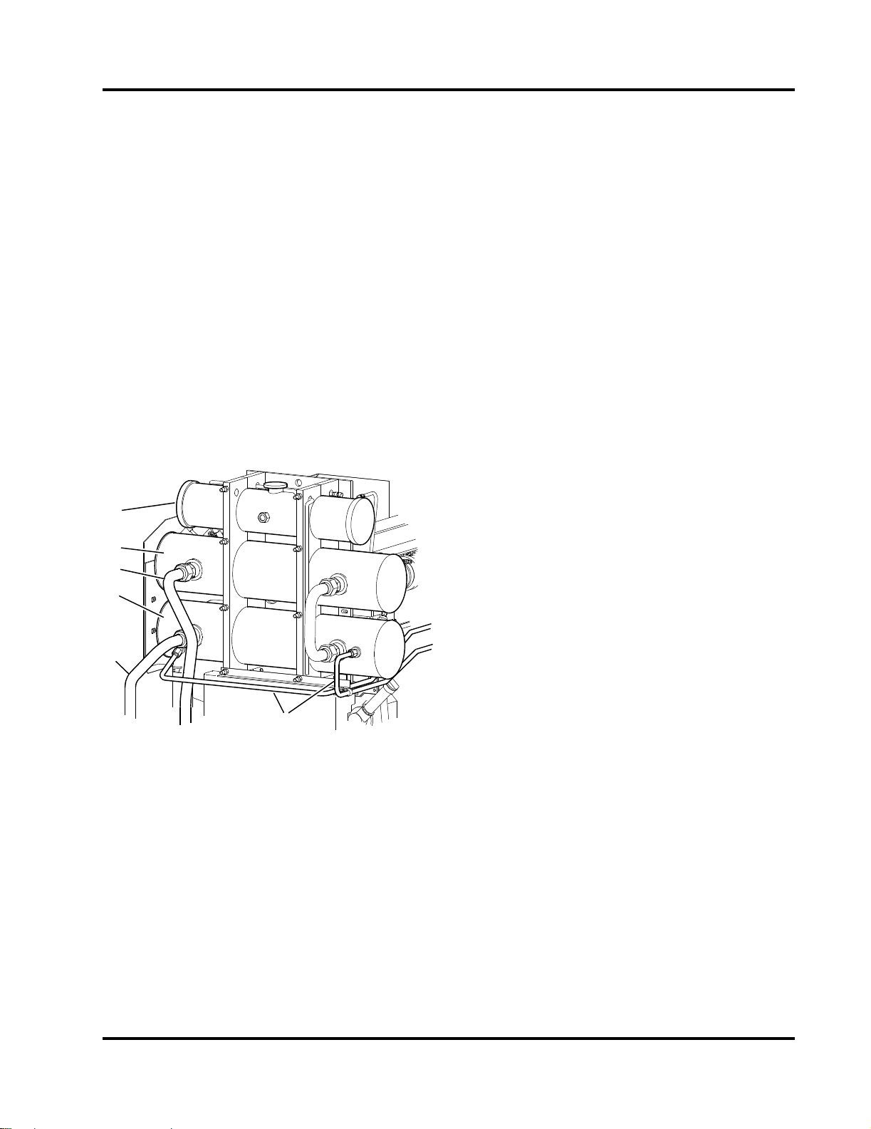
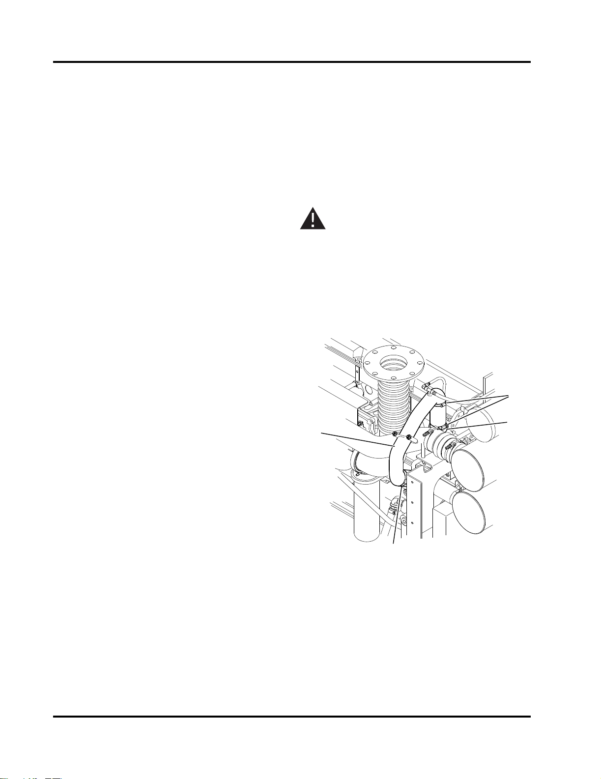
1. Engine Coolant Expansion Tank
2. Charge Air Cooler (CAC) Heat Exchanger
3. Raw Water Inlet Pipe
4. Coolant/Fuel Cooler Heat Exchanger
5. Raw Water Outlet Pipe
6. Fuel Cooling Lines
Figure 3-7 Cooling Loop Heat Exchangers
4. Use a 5 gallon container to measure and time
the flow from discharge pipe.
Flow rate = time to fill container/container.
Example: Time to fill 5 gallon container = 15 seconds.
Fire Power Pump Engine CFP15E
Doc. 9779, Rev. 05-09
in SAE standard J537. All battery information is for
lead/acid batteries.
3.5.1 Battery Requirements
Two redundant sets of batteries must be supplied for
the standard 24 VDC operating voltage. Refer to
National Fire Protection Association, NFPA 20,
Chapter 11 and Section 1 - Safety of this manual for
additional battery installation information.
IMPORTANT: Batteries must meet the requirement
listed in Electrical System Specifications. Batteries
may be supplied by Cummins Fire Power, or
Cummins Inc. as an option or may be supplied by the
customer.
3-5
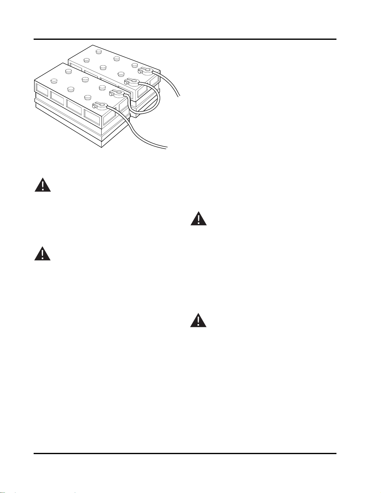
WARNING
2. Locate the batteries near the engine or increase
CFP-014
the size of the conductors as required by applicable codes. Ensure that the batteries are configured properly for 24 VDC standard operations.
Refer to Figure 3-8.
3. Check the battery cables and connections.
NOTE: Coat the terminals with petroleum jelly to
prevent corrosion. Install the cables and tighten the
battery connections.
3.5.3 Auxiliary Battery Starting
If a battery charging system is not provided, the
engine can be started using charged batteries.
Figure 3-8 Series Battery Connection - 24 VDC
Battery electrolyte (sulfuric acid) is highly caustic
and can burn clothing, and skin. Wear acid impervious neoprene gloves, and safety goggles or full
face shield, when working with the batteries.
Always disconnect the negative (-) battery cable
first and attach the negative (-) battery cable last.
CAUTION
DO NOT connect battery charging cables to any
electronic control system component. This can
damage the electronic control system.
NOTE: Use the inductive charging-cranking systems
analyzer, Cummins Part Number 3377193, to test the
output amperage of either maintenance-free or conventional vent cap batteries. Follow the instructions
provided with the test equipment.
3.5.2 Battery Installation
Install the Loose Wire Kit per instructions on
Cummins Drawing 9768. If purchased, install the
optional Battery Cable Kit (Cummins Fire Power Part
No. 14852). Otherwise, install equivalent customer
supplied wiring. Install battery sets in a well ventilated
or otherwise protected location.
NOTE: There are two possible heavy-duty battery
connections: Battery terminal and clamp or threaded
battery terminal and nut.
1. Provide adequate room for servicing or replacing
the batteries. Provide protection from extremes
of temperature and weather.
NOTE: For maintainable lead acid batteries supplied
by Cummins Fire Power, or Cummins Inc., check the
state of charge by measuring battery cell specific
gravity. Refer to Battery Testing in Section 6 - Mainte-
nance for additional information.
WARNING
Batteries can emit explosive gases during charging. Always ventilate the compartment before servicing the batteries. Remove sources of spark or
open flame. To avoid arcing, remove the negative
(-) battery cable first and attach the negative (-)
battery cable last.
3.6 Signal and Control Installation
This section explains how to connect the controller
wires to the terminal block.
CAUTION
If the batteries have been installed prior to the
control wiring, disconnect the negative (-) cable
first and then disconnect the positive (+) battery
lead. Install the cables with the positive (+) cable
first and the negative (-) cable last before testing.
NOTE: Install signal and control wiring at Terminal
Board TB. Refer to the terminal wiring schematic
decal on the inside of the instrument enclosure.
1. Ensure that the fire control system is properly
installed and configured per the manufacturer’s
instructions. Refer to the Wiring Schematic
Drawings provided with the pump manual.
3-6
Fire Power Pump Engine CFP15E
Doc. 9779, Rev. 05-09
303
CFP-044
302
301
12
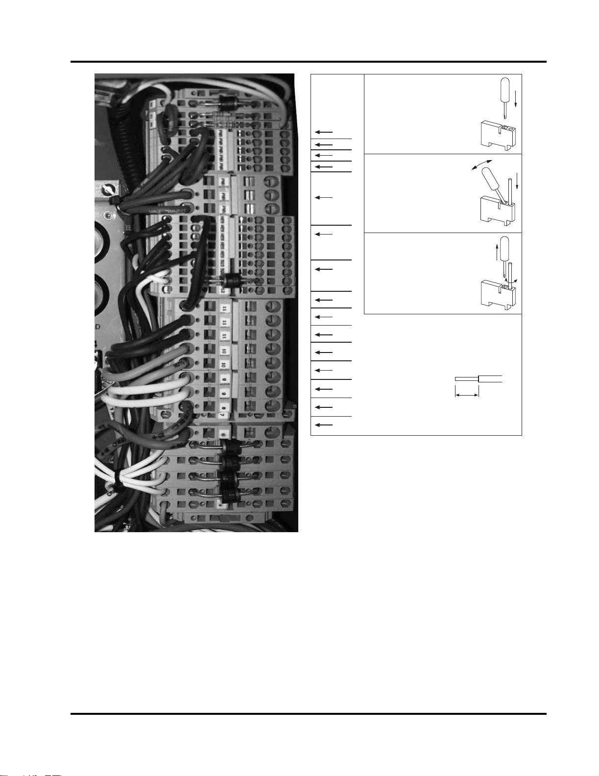
INSERT FLAT SCREW DRIVER
INTO THE SQUARE HOLE
PRY OPEN THE SPRING
CLAMP WITH THE
SCREW DRIVER
11
10
9
8
7
6
5
4
3
2
1
INSERT THE STRIPPED
LEAD WIRE INTO THE
ROUND HOLE.
RELEASE THE SCREW DRIVER.
VERIFY THAT THE
STRIPPED PORTION OF
THE LEAD WIRE (AND
NOT THE INSULATION)
IS CLAMPED BY LIGHTLY
TUGGING ON THE WIRE.
STRIP LENGTH
1/2 INCH
Figure 3-9 Termination Blocks and Wiring Decal
2. Complete the fire pump controller wiring (customer supplied) per the manufacturer’s instructions.
3. Connect the following wires to the Fire Pump
Engine Instrument Panel per the engine electrical diagrams. Refer to Figure 3-9.
a. TB-1: Connect the Control Power from the
Fire Pump Controller. This power source is
necessary for fire pump operations while in
the AUTO Mode.
Fire Power Pump Engine CFP15E
Doc. 9779, Rev. 05-09
b. TB-2: Connect the Crank Terminate input
signal for the Fire Pump Controller. This
signal is present when the engine is running.
This signal indicates that the engine has
started and that the crank command from the
fire pump controller should stop immediately.
c. TB-3: Connect the remote Overspeed Alarm
Input to the Fire Pump Controller. This signal
is present when the overspeed switch has
operated. If this event occurs, the fire pump
engine will stop.
3-7
d. TB-4: Connect the Low Oil Pressure Alarm
2
1
2
3
CFP-143
Input from the Fire Pump Controller. This 0
VDC grounded signal is present when the oil
pressure has dropped below the 110 ±
kPa (16 ± 2 psig) Set Point.
e. TB-5: Connect the High Coolant Tempera-
ture Alarm Input from the Fire Pump Controller. This 0 VDC grounded signal is activated
when the engine is running and the coolant
temperature is at or above 93° C (200° F).
The alarm will deactivate when the engine is
running and the coolant temperature drops
below 88° C (190° F).
f. TB-6: Connect Battery Set “A” lead from the
controller. The controller senses Battery A
charge state and charges the battery through
this heavy gauge wire.
g. TB-8: Connect Battery Set “B” lead from the
controller. The controller senses Battery B
charge state and charges the battery through
this heavy gauge wire.
13
5. Provide the initial charge on the redundant batteries per the battery charger’s instructions.
6. 6. Check that both voltmeters on the operator’s
control panel indicate the approximate battery
voltage.
3.7 Coolant System Preparation
The fire pump engine cooling and lubrication system
was initially filled during manufacture and testing.
CAUTION
Ensure that all cooling and lubrication systems
have been filled to the proper level before operation.
1. Inspect the engine coolant hoses and hose
clamps. Ensure that all coolant hoses and
clamps are properly installed and tight. Refer to
Figure 3-10 and Figure 3-11.
h. TB-9: Connect Crank From Battery A Lead.
During a cranking cycle, the controller energizes the coil of Starter Contactor A through
terminal TB-9 to start the engine.
i. TB-10: Connect Crank From Battery B Lead.
During a cranking cycle, the controller energizes the coil of Starter Contactor B through
terminal TB-10 to start the engine.
j. TB-11: Connect the “Battery Ground” lead
from the controller. This heavy gauge wire
provides a common ground between the
engine and controller.
k. TB-301: Connect the “Operating On Alternate
ECM” lead. This 0 VDC ground signal is
present when the engine’s ECM selector
switch is set to ECM-B.
l. TB-302: Connect the “ECM / Fuel Fault”
signal wire. This 0 VDC ground signal is
present when the engine signals a trouble
fault.
4. Ensure electrical continuity and adequate insulation resistance for the installed wiring.
1. Upper Coolant Hose
2. Hose Clamps
3. Thermostat Housing Flange
Figure 3-10 Upper Cooling Hose Clamps
2. Ensure that the engine coolant level is visible at
the center of the expansion tank sight gauge.
Add coolant as required. DO NOT OVERFILL!
a. If engine coolant temperature is below 50° C
(122° F), remove the expansion tank pressure/fill cap. Refer to Figure 3-12.
3-8
Fire Power Pump Engine CFP15E
Doc. 9779, Rev. 05-09
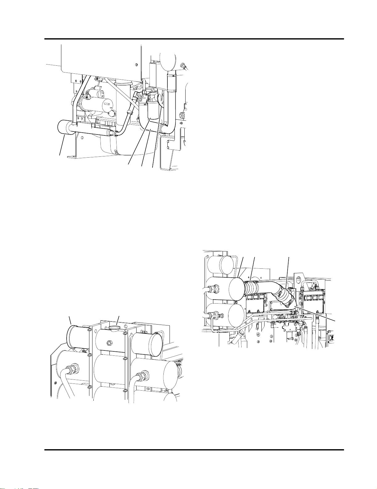
3. The engine coolant heater must maintain an
4
3
2
1
CFP-079
2
1
CFP-078
CFP-080
2
2
3
1
engine coolant temperature of 49° C (120° F) or
above. Refer to Figure 3-11.
Ensure that coolant is present in the engine
heater before plugging in the heater element.
3.8 Charge Air Cooler System
The charge air cooler system reduces the temperature of the compressed combustion air from the turbocharger before entering the air intake manifold.
Refer to Figure 3-13 and Figure 3-14.
1. Inspect the charge air cooler piping and hoses
for loose/missing hose clamps, hose punctures,
leaking manifold seals, or corrosion. Torque the
hose clamps to 8 N-m (72 in-lb).
1. Engine Heater
2. Coolant Filter
3. Lower Coolant Hose
4. Coolant Pump
Figure 3-11 Coolant Circulation System
NOTE: Supplemental engine coolant should be a
mixture of 50% ethylene glycol anti-freeze and 50%
water to avoid engine damage. Refer to Anti-freeze
information found in Section 6 - Maintenance for additional information.
b. Check and correct any cooling system leaks.
c. Install the pressure/fill cap on the Coolant
Expansion Tank.
2. After the engine starts, a whistling noise may
indicate an air leak from the turbocharger to discharge elbow connection, loose hose clamps,
damaged manifold seals, missing hose clamps,
or hose punctures.
3. Inspect for damage. Tighten loosen clamps.
Torque hose clamp screws to 8 N-m (72 in-lb).
1. Charge Air Cooler (CAC) Heat Exchanger
2. CAC Tubing and Clamps
3. Intake Manifold
Figure 3-13 Charge Air Cooler Tubing
1. Engine Coolant Expansion Tank
2. Coolant Expansion Tank Pressure/Fill Cap
Figure 3-12 Engine Coolant Expansion Tank
Fire Power Pump Engine CFP15E
3-9
Doc. 9779, Rev. 05-09
 Loading...