

Page 1

OperatorOperator ManualManual
Generator Set with QSJ5.9G Engine and
PowerCommand® 1.1 Control
C45 N6 (Spec A)
C50 N6 (Spec A)
C60 N6 (Spec A)
C70 N6 (Spec A)
C80 N6 (Spec A)
C100 N6 (Spec A)
English
Original Instructions
8-2017 A051X877 (Issue 6)
Page 2
Page 3

Table of Contents
1. IMPORTANT SAFETY INSTRUCTIONS ....................................................................................... 1
1.1 Warning, Caution, and Note Styles Used in This Manual ..................................................... 1
1.2 General Information ................................................................................................................ 1
1.3 Generator Set Safety Code .................................................................................................... 4
1.4 Moving Parts Can Cause Severe Personal Injury or Death ................................................... 4
1.5 Electrical Shocks and Arc Flashes Can Cause Severe Personal Injury or Death.................. 5
1.6 Fuel and Fumes Are Flammable ............................................................................................ 5
1.7 Batteries Can Explode ............................................................................................................ 6
1.8 Exhaust Gases Are Deadly..................................................................................................... 7
1.9 The Hazards of Carbon Monoxide.......................................................................................... 9
1.10 Earth Ground Connection ..................................................................................................... 9
2. INTRODUCTION.......................................................................................................................... 11
2.1 Safety .................................................................................................................................... 11
2.2 About This Manual................................................................................................................ 11
2.3 Schedule of Abbreviations .................................................................................................... 12
2.4 Related Literature ................................................................................................................. 14
2.5 Model Specifications ............................................................................................................. 15
2.6 After Sales Services.............................................................................................................. 19
2.7 General Operating Conditions .............................................................................................. 20
2.8 Generator Set Nameplate .................................................................................................... 21
2.9 Manufacturing Facilities ........................................................................................................ 23
3. CONTROL SYSTEM .................................................................................................................... 25
3.1 Control System Description .................................................................................................. 25
3.2 Display Text or Symbolic Version ......................................................................................... 29
3.3 Exercise Settings ................................................................................................................. 30
3.4 Brightness and Contrast ....................................................................................................... 38
3.5 History and About Menu ....................................................................................................... 40
3.6 Fault Log ............................................................................................................................... 42
3.7 Selecting Operating Modes................................................................................................... 44
3.8 Operating Modes .................................................................................................................. 49
4. OPERATION - POWERCOMMAND 1.1 ...................................................................................... 51
4.1 Introduction ........................................................................................................................... 51
4.2 General Operating Conditions .............................................................................................. 51
4.3 Generator Set Operation....................................................................................................... 51
5. MAINTENANCE ........................................................................................................................... 63
5.1 Maintenance Safety .............................................................................................................. 63
5.2 Periodic Maintenance ........................................................................................................... 66
5.3 Exercising the Generator Set ............................................................................................... 71
5.4 Engine Oil ............................................................................................................................. 71
iA051X877 (Issue 6) Copyright © 2017 Cummins Inc.
Page 4

Table of Contents 8-2017
5.5 Air Intake System.................................................................................................................. 77
5.6 Batteries ................................................................................................................................ 79
5.7 Spark Plugs .......................................................................................................................... 83
6. TROUBLESHOOTING ................................................................................................................. 85
6.1 Avoiding Generator Set Shutdowns ..................................................................................... 85
6.2 Fault Code Introduction......................................................................................................... 85
6.3 Engine Is Difficult to Start or Does Not Start ........................................................................ 85
6.4 Code 143 - Engine Oil Pressure Low (Warning) .................................................................. 86
6.5 Codes 146 and 151 - Engine Coolant Temperature High (Warning or Shutdown) .............. 86
6.6 Code 155 - Intake Manifold Temperature High (Shutdown) ................................................. 87
6.7 Code 197 - Coolant Level Low (Warning) ............................................................................ 87
6.8 Code 415 - Engine Oil Pressure Low (Shutdown)................................................................ 88
6.9 Code 441 - Battery Voltage Low (Warning).......................................................................... 88
6.10 Code 488 - Intake Manifold Temperature High (Warning).................................................. 89
6.11 Code 1438 - Fail to Crank (Shutdown) ............................................................................... 90
6.12 Code 1472 - High AC Current (Shutdown) ......................................................................... 90
6.13 Code 5134 - Unknown Shutdown at Idle ............................................................................ 90
ii A051X877 (Issue 6)Copyright © 2017 Cummins Inc.
Page 5
1 IMPORTANT SAFETY INSTRUCTIONS
SAVE THESE INSTRUCTIONS. This manual contains important instructions that
should be followed during installation and maintenance of the generator set and
batteries.
Safe and efficient operation can be achieved only if the equipment is properly
operated and maintained. Many accidents are caused by failure to follow
fundamental rules and precautions.
1.1 Warning, Caution, and Note Styles Used in This Manual
The following safety styles and symbols found throughout this manual indicate
potentially hazardous conditions to the operator, service personnel, or equipment.
DANGER
Indicates a hazardous situation that, if not avoided, will result in death or
serious injury.
WARNING
Indicates a hazardous situation that, if not avoided, could result in death or
serious injury.
Indicates a hazardous situation that, if not avoided, could result in minor or
moderate injury.
Indicates information considered important, but not hazard-related (e.g.,
messages relating to property damage).
1.2 General Information
This manual should form part of the documentation package supplied by Cummins
Inc. with specific generator sets. If this manual has been supplied in isolation,
please contact your authorized dealer.
It is in the operator's interest to read and understand all warnings and
cautions contained in the documentation relevant to the generator set
operation and daily maintenance.
CAUTION
NOTICE
NOTICE
1A051X877 (Issue 6) Copyright © 2017 Cummins Inc.
Page 6
1. IMPORTANT SAFETY INSTRUCTIONS 8-2017
General Safety Precautions
WARNING
Hot Pressurized Liquid
Contact with hot liquid can cause severe burns.
Do not open the pressure cap while the engine is running. Let the engine
cool down before removing the cap. Turn the cap slowly and do not open it
fully until the pressure has been relieved.
WARNING
Moving Parts
Moving parts can cause severe personal injury.
Use extreme caution around moving parts. All guards must be properly
fastened to prevent unintended contact.
WARNING
Toxic Hazard
Used engine oils have been identified by some state and federal agencies to
cause cancer or reproductive toxicity.
Do not ingest, breathe the fumes, or contact used oil when checking or
changing engine oil. Wear protective gloves and face guard.
WARNING
Electrical Generating Equipment
Incorrect operation and maintenance can result in severe personal injury or
death.
Do not operate equipment when fatigued, or after consuming any alcohol or
drug.
Make sure that only suitably trained and experienced service personnel
perform electrical and/or mechanical service.
WARNING
Toxic Gases
Substances in exhaust gases have been identified by some state and federal
agencies to cause cancer or reproductive toxicity.
Do not breathe in or come into contact with exhaust gases.
WARNING
High Noise Level
Generator sets in operation emit noise, which can cause hearing damage.
Wear appropriate ear protection at all times.
2 A051X877 (Issue 6)Copyright © 2017 Cummins Inc.
Page 7
1. IMPORTANT SAFETY INSTRUCTIONS8-2017
WARNING
Hot Surfaces
Contact with hot surfaces can cause severe burns.
The unit is to be installed so that the risk of hot surface contact by people is
minimized. Wear appropriate PPE when working on hot equipment and avoid
contact with hot surfaces.
WARNING
Toxic Hazard
Ethylene glycol, used as an engine coolant, is toxic to humans and animals.
Wear appropriate PPE. Clean up coolant spills and dispose of used coolant
in accordance with local environmental regulations.
WARNING
Combustible Liquid
Ignition of combustible liquids is a fire or explosion hazard which can cause
severe burns or death.
Do not store fuel, cleaners, oil, etc., near the generator set. Do not use
combustible liquids like ether.
WARNING
Combustible Gases
Generator sets in operation have combustible gases under pressure, which
if ignited can cause eye and ear damage.
Wear appropriate eye and ear protection at all times.
WARNING
Combustible Gases
Generator sets in operation have combustible gases under pressure, which
if ignited can cause severe injury.
Do not operate the generator set with any doors open.
WARNING
Fire Hazard
Materials drawn into the generator set, as well as accumulated grease and
oil, are a fire hazard. Fire can cause severe burns or death.
Keep the generator set and the surrounding area clean and free from
obstructions. Make sure the generator set is mounted in a manner to prevent
combustible materials from accumulating under the unit.
3A051X877 (Issue 6) Copyright © 2017 Cummins Inc.
Page 8
1. IMPORTANT SAFETY INSTRUCTIONS 8-2017
WARNING
Automated Machinery
Accidental or remote starting of the generator set can cause severe personal
injury or death.
Isolate all auxiliary supplies and use an insulated wrench to disconnect the
starting battery cables (negative [–] first).
NOTICE
Keep multi-type ABC fire extinguishers close by. Class A fires involve
ordinary combustible materials such as wood and cloth. Class B fires
involve combustible and flammable liquid fuels and gaseous fuels. Class C
fires involve live electrical equipment. (Refer to NFPA No. 10 in the
applicable region.)
NOTICE
Before performing maintenance and service procedures on enclosed
generator sets, make sure the service access doors are secured open.
NOTICE
Stepping on the generator set can cause parts to bend or break, leading to
electrical shorts, or to fuel, coolant, or exhaust leaks. Do not step on the
generator set when entering or leaving the generator set room.
1.3 Generator Set Safety Code
Before operating the generator set, read the manuals and become familiar with
them and the equipment. Safe and efficient operation can be achieved only if
the equipment is properly operated and maintained. Many accidents are caused
by failure to follow fundamental rules and precautions.
WARNING
Electrical Generating Equipment
Incorrect operation and maintenance can result in severe personal injury or
death.
Read and follow all Safety Precautions, Warnings, and Cautions throughout
this manual and the documentation supplied with the generator set.
1.4 Moving Parts Can Cause Severe Personal Injury or Death
• Keep hands, clothing, and jewelry away from moving parts.
4 A051X877 (Issue 6)Copyright © 2017 Cummins Inc.
Page 9

1. IMPORTANT SAFETY INSTRUCTIONS8-2017
• Before starting work on the generator set, disconnect the battery charger from
its AC source, then disconnect the starting batteries using an insulated wrench,
negative (–) cable first. This will prevent accidental starting.
• Make sure that fasteners on the generator set are secure. Tighten supports and
clamps; keep guards in position over fans, drive belts, etc.
• Do not wear loose clothing or jewelry in the vicinity of moving parts or while
working on electrical equipment. Loose clothing and jewelry can become
caught in moving parts.
• If any adjustments must be made while the unit is running, use extreme caution
around hot manifolds, moving parts, etc.
1.5 Electrical Shocks and Arc Flashes Can Cause Severe Personal Injury or Death
• Only qualified service personnel certified and authorized to work on power
circuits should work on exposed energized power circuits.
• All relevant service material must be available for any electrical work performed
by certified service personnel.
• Exposure to energized power circuits with potentials of 50 VAC or 75 VDC or
higher poses a significant risk of electrical shock and electrical arc flash.
• Refer to standard NFPA 70E, or equivalent safety standards in corresponding
regions, for details of the dangers involved and for safety requirements.
1.6 Fuel and Fumes Are Flammable
Fire, explosion, and personal injury or death can result from improper practices.
• Do not fill fuel tanks while the engine is running unless the tanks are outside
the engine compartment. Fuel contact with hot engine or exhaust is a potential
fire hazard.
• Do not permit any flame, cigarette, pilot light, spark, arcing equipment, or other
ignition source near the generator set or fuel tank.
• Fuel lines must be adequately secured and free of leaks. Fuel connection at the
engine should be made with an approved flexible line. Do not use copper piping
on flexible lines as copper will become brittle if continuously vibrated or
repeatedly bent.
• Make sure all fuel supplies have a positive shutoff valve.
• Make sure the battery area has been well-ventilated prior to servicing near it.
Lead-acid batteries emit a highly explosive hydrogen gas that can be ignited by
arcing, sparking, smoking, etc.
5A051X877 (Issue 6) Copyright © 2017 Cummins Inc.
Page 10

1. IMPORTANT SAFETY INSTRUCTIONS 8-2017
Do Not Operate in Flammable and Explosive Environments
Flammable vapor can cause an engine to over speed and become difficult to stop,
resulting in possible fire, explosion, severe personal injury, and death. Do not
operate a generator set where a flammable vapor environment can be created,
unless the generator set is equipped with an automatic safety device to block the air
intake and stop the engine. The owners and operators of the generator set are
solely responsible for operating the generator set safely. Contact your authorized
Cummins distributor for more information.
Spillage
Any spillage that occurs during fueling, oil top-off, or oil change must be cleaned up
before starting the generator set.
Fluid Containment
NOTICE
Where spillage containment is not part of a Cummins supply, it is the
responsibility of the installer to provide the necessary containment to
prevent contamination of the environment, especially water courses and
sources.
If fluid containment is incorporated into the bedframe, it must be inspected at
regular intervals. Any liquid present should be drained out and disposed of in line
with local health and safety regulations. Failure to perform this action may result in
spillage of liquids which could contaminate the surrounding area.
Any other fluid containment area must also be checked and emptied, as described
above.
1.7 Batteries Can Explode
Batteries can explode, causing severe skin and eye burns and can release toxic
electrolytes.
Combustible Gases
Batteries can explode, causing severe skin and eye burns, and can release
toxic electrolytes.
Do not dispose of the battery in a fire, because it is capable of exploding. Do
not open or mutilate the battery. Do not charge frozen batteries.
WARNING
6 A051X877 (Issue 6)Copyright © 2017 Cummins Inc.
Page 11

1. IMPORTANT SAFETY INSTRUCTIONS8-2017
WARNING
Electric Shock Hazard
Batteries present the risk of high short circuit current.
When servicing the generator set:
• Remove watches, rings, or other metal objects.
• Use tools with insulated handles.
NOTICE
Servicing of batteries must be performed or supervised by personnel
knowledgeable of batteries and the required precautions. Keep unauthorized
personnel away from batteries.
• Wear safety glasses.
• Do not smoke.
• Do not charge frozen batteries.
• To prevent arcing when disconnecting the battery:
1. Press the Off switch from the display and then press the E-Stop button.
2. Disconnect AC power from any battery chargers.
3. Remove the negative (-) battery cable to prevent starting.
• To prevent arcing when reconnecting the battery:
1. Reconnect the positive (+) cable.
2. Reconnect the negative (-) cable.
3. Reconnect the battery charger to AC power supply.
• When replacing the generator set battery, always replace it with a battery as
specified in this manual.
1.8 Exhaust Gases Are Deadly
• Provide an adequate exhaust system to properly expel discharged gases away
from enclosed or sheltered areas, and areas where individuals are likely to
congregate. Visually and audibly inspect the exhaust system daily for leaks per
the maintenance schedule. Make sure that exhaust manifolds are secured and
not warped. Do not use exhaust gases to heat a compartment.
• Make sure the unit is well ventilated.
7A051X877 (Issue 6) Copyright © 2017 Cummins Inc.
Page 12
1. IMPORTANT SAFETY INSTRUCTIONS 8-2017
Exhaust Precautions
WARNING
Hot Exhaust Gases
Contact with hot exhaust gases can cause severe burns.
Wear personal protective equipment when working on equipment.
WARNING
Hot Surfaces
Contact with hot surfaces can cause severe burns.
The unit is to be installed so that the risk of hot surface contact by people is
minimized. Wear appropriate PPE when working on hot equipment and avoid
contact with hot surfaces.
WARNING
Toxic Gases
Inhalation of exhaust gases can cause asphyxiation and death.
Pipe exhaust gas outside and away from windows, doors, or other inlets to
buildings. Do not allow exhaust gas to accumulate in habitable areas.
WARNING
Fire Hazard
Contaminated insulation is a fire hazard. Fire can cause severe burns or
death.
Remove any contaminated insulation and dispose of it in accordance with
local regulations.
The exhaust outlet may be sited at the top or bottom of the generator set. Make
sure that the exhaust outlet is not obstructed. Personnel using this equipment must
be made aware of the exhaust position. Position the exhaust away from flammable
materials - in the case of exhaust outlets at the bottom, make sure that vegetation is
removed from the vicinity of the exhaust.
The exhaust pipes may have some insulating covers fitted. If these covers become
contaminated they must be replaced before the generator set is run.
To minimize the risk of fire, make sure the following steps are observed:
• Make sure that the engine is allowed to cool thoroughly before performing
maintenance or operation tasks.
• Clean the exhaust pipe thoroughly.
8 A051X877 (Issue 6)Copyright © 2017 Cummins Inc.
Page 13

1. IMPORTANT SAFETY INSTRUCTIONS8-2017
1.9 The Hazards of Carbon Monoxide
Carbon monoxide (CO) is an odorless, colorless, tasteless and non-irritating gas.
You cannot see it or smell it. Red blood cells, however, have a greater affinity for
CO than for oxygen. Therefore, exposure even to low levels of CO for a prolonged
period can lead to asphyxiation (lack of oxygen) resulting in death. Mild effects of
CO poisoning include eye irritation, dizziness, headaches, fatigue and the inability to
think clearly. More extreme symptoms include vomiting, seizures and collapse.
Engine-driven generator sets produce harmful levels of carbon monoxide that can
injure or kill you.
Special Risks of CO near the Home
WARNING
Toxic Gases
Carbon monoxide (CO) gas can cause nausea, fainting, or death. Residents
can be exposed to lethal levels of CO when the generator set is running.
Depending on air temperature and wind, CO can accumulate in or near the
home.
To protect yourself and others from the dangers of CO poisoning, it is
recommended that reliable, approved, and operable CO detector alarms are
installed in proper locations in the home as specified by their manufacturer.
Protecting Yourself from CO Poisoning
• Locate the generator set in an area where there are no windows, doors, or
other access points into the home.
• Make sure all CO detectors are installed and working properly.
• Pay attention for signs of CO poisoning.
• Check the exhaust system for corrosion, obstruction, and leaks every time you
start the generator set and every eight hours when you run it continuously.
1.10 Earth Ground Connection
The neutral of the generator set may be required to be bonded to earth ground at
the generator set location, or at a remote location, depending on system design
requirements. Consult the engineering drawings for the facility or a qualified
electrical design engineer for proper installation.
NOTICE
The end user is responsible to make sure that the ground connection point
surface area is clean and free of rust before making a connection.
9A051X877 (Issue 6) Copyright © 2017 Cummins Inc.
Page 14

1. IMPORTANT SAFETY INSTRUCTIONS 8-2017
NOTICE
The end user is responsible for making sure that an earthing arrangement
that is compliant with local conditions is established and tested before the
equipment is used.
10 A051X877 (Issue 6)Copyright © 2017 Cummins Inc.
Page 15

2 Introduction
2.1 Safety
Hazardous Voltage
Contact with high voltages can cause severe electrical shock, burns, or
death.
Make sure that only a trained and experienced electrician makes generator
set electrical output connections, in accordance with the installation
instructions and all applicable codes.
Electrical Generating Equipment
Faulty electrical generating equipment can cause severe personal injury or
death.
Generator sets must be installed, certified, and operated by trained and
experienced person in accordance with the installation instructions and all
applicable codes.
WARNING
WARNING
2.2 About This Manual
The purpose of this manual is to provide the users with sound, general information.
It is for guidance and assistance with recommendations for correct and safe
procedures. Cummins Inc. cannot accept any liability whatsoever for problems
arising as a result of following recommendations in this manual.
The information contained within the manual is based on information available at the
time of going to print. In line with Cummins Inc. policy of continuous development
and improvement, information may change at any time without notice. The users
should therefore make sure that they have the latest information available before
starting any work. The latest version of this manual is available on QuickServe
Online (https://quickserve.cummins.com).
Users are respectfully advised that, in the interests of good practice and safety, it is
their responsibility to employ competent people to carry out any installation work.
Consult your authorized dealer for further installation information. It is essential that
the utmost care is taken with the application, installation, and operation of any
generator set due to their potentially hazardous nature. Careful reference should
also be made to other Cummins Inc. literature. You must operate and maintain your
generator set properly if you are to expect safe and reliable operation.
For further assistance, contact your authorized Cummins dealer.
11A051X877 (Issue 6) Copyright © 2017 Cummins Inc.
Page 16

2. Introduction 8-2017
NOTICE
This device complies with part 15 of the FCC rules. Operation is subject to
the following two conditions:
• This device may not cause harmful interferences.
• This device must accept any interference received, including
interference that may cause undesired operation.
2.3 Schedule of Abbreviations
This list is not exhaustive. For example, it does not identify units of measure or
acronyms that appear only in parameters, event/fault names, or part/accessory
names.
AmpSentry, INSITE, and InPower are trademarks of Cummins Inc. PowerCommand
is a registered trademark of Cummins Inc.
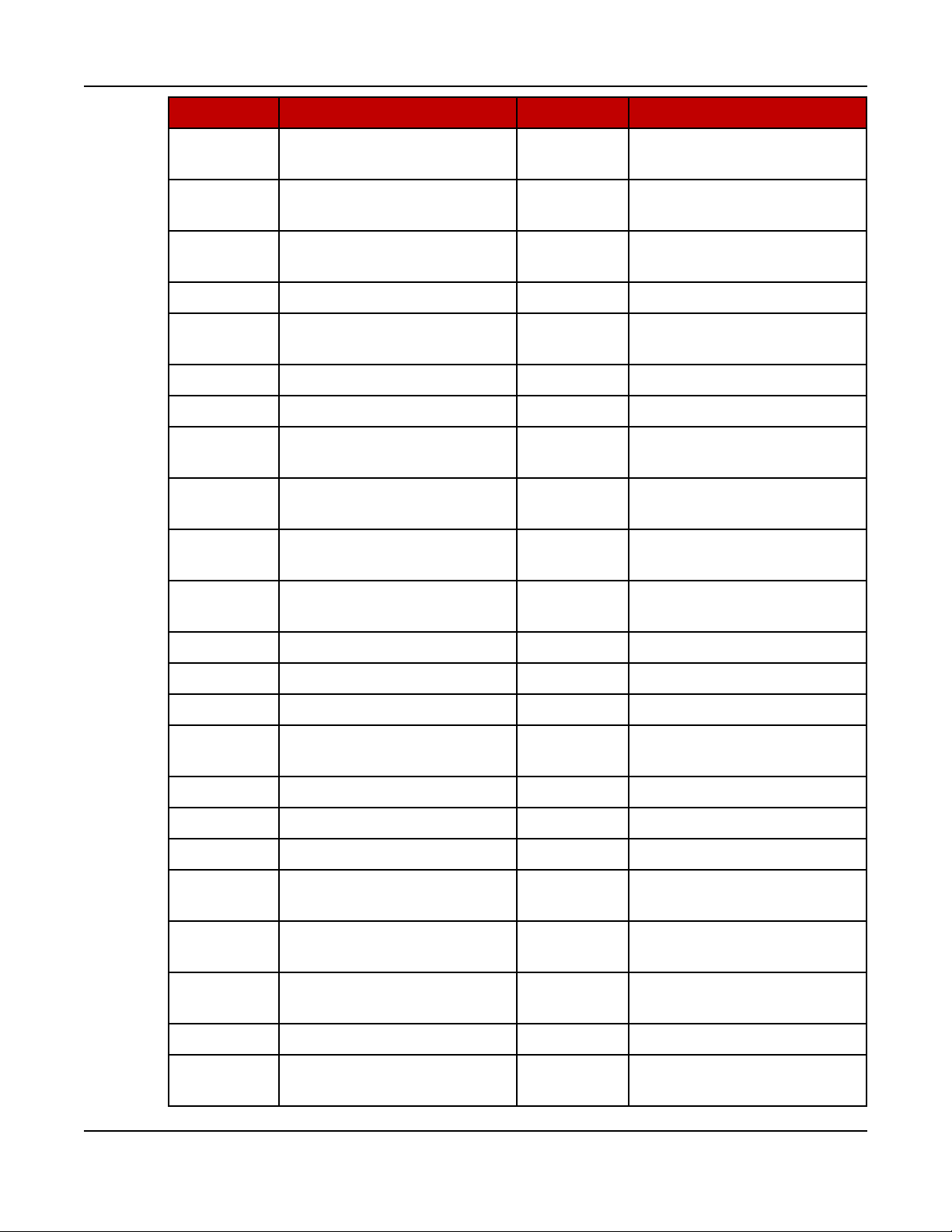
ABBR. DESCRIPTION ABBR. DESCRIPTION
AC Alternating Current LED Light-emitting Diode
AMP AMP, Inc., part of Tyco
Electronics
ANSI American National
Standards Institute
ASOV Automatic Shut Off Valve MFM Multifunction Monitor
ASTM American Society for
Testing and Materials
(ASTM International)
ATS Automatic Transfer Switch MLD Masterless Load Demand
AVR Automatic Voltage
Regulator
AWG American Wire Gauge NC Not Connected
CAN Controlled Area Network NFPA National Fire Protection
CB Circuit Breaker NO Normally Open
CE Conformité Européenne NWF Network Failure
LTS Long Term Storage
LVRT Low Voltage Ride Through
Mil Std Military Standard
NC Normally Closed
Agency
CFM Cubic Feet per Minute OEM Original Equipment
Manufacturer
CGT Cummins Generator
Technologies
12 A051X877 (Issue 6)Copyright © 2017 Cummins Inc.
OOR Out of Range
Page 17
2. Introduction8-2017
ABBR. DESCRIPTION ABBR. DESCRIPTION
CMM Cubic Meters per Minute OORH /
Out of Range High
ORH
CT Current Transformer OORL /
Out of Range Low
ORL
D-AVR Digital Automatic Voltage
PB Push Button
Regulator
DC Direct Current PCC PowerCommand®Control
DEF Diesel Exhaust Fluid PGI Power Generation
Interface
DPF Diesel Particulate Filter PGN Parameter Group Number
ECM Engine Control Module PI Proportional/Integral
ECS Engine Control System PID Proportional / Integral /
Derivative
EMI Electromagnetic
interference
PLC Programmable Logic
Controller
EN European Standard PMG Permanent Magnet
Generator
EPS Engine Protection System PPE Personal Protective
Equipment
E-Stop Emergency Stop PT Potential Transformer
FAE Full Authority Electronic PTC Power Transfer Control
FMI Failure Mode Identifier PWM Pulse-width Modulation
FRT Fault Ride Through RFI Radio Frequency
Interference
FSO Fuel Shutoff RH Relative Humidity
Genset Generator Set RMS Root Mean Square
GCP Generator Control Panel RTU Remote Terminal Unit
GND Ground SAE Society of Automotive
Engineers
LCT Low Coolant Temperature SCR Selective Catalytic
Reduction
HMI Human-machine Interface SPN Suspect Parameter
Number
IC Integrated Circuit SWL Safe Working Load
ISO International Organization
for Standardization
13A051X877 (Issue 6) Copyright © 2017 Cummins Inc.
SW_B+ Switched B+
Page 18

2. Introduction 8-2017
ABBR. DESCRIPTION ABBR. DESCRIPTION
LBNG Lean-burn Natural Gas UL Underwriters Laboratories
LCD Liquid Crystal Display UPS Uninterruptible Power
Supply
2.4 Related Literature
Before any attempt is made to operate the generator set, the operator should take
time to read all of the manuals supplied with the generator set, and to familiarize
themselves with the warnings and operating procedures.
The literature provided with the generator set is as follows:
• Operator Manual (A051X877)
• Installation Manual (A051X873)
NOTICE
A generator set must be operated and maintained properly if you are to
expect safe and reliable operation. The Operator manual includes a
maintenance schedule and a troubleshooting guide.
The Health and Safety manual must be read in conjunction with this manual
for the safe operation of the generator set:
• Health and Safety Manual (0908-0110)
• Warranty Statement (A028U870)
• C45 N6, C50 N6 and C60 N6 models only: Emissions Component Defect
Warranty Statement (A028X278)
• C70 N6, C80 N6 and C100 N6 models only: Emissions Component Defect
Warranty Statement (A028X279)
The relevant manuals appropriate to your generator set are also available. The
documents below are in English:
• Service Manual (A051X880)
• Parts Manual (A051X891)
• EControls, Inc., Global Control Platform (GCP) Software Service Manual
(A035C596)
• EControls, Inc., 4G Software Service Manual (A052G032)
• EControls, Inc., GCP Engine Display Interface Software (EDIS) Training
Manual (A035C608)
• EControls, Inc., 4G Software Operator Manual (A052G024)
• Engine Operation & Maintenance Manual for QSJ5.9G (4388606)
• RA Series Transfer Switch Owner Manual (A046S594) - if applicable
14 A051X877 (Issue 6)Copyright © 2017 Cummins Inc.
Page 19
• PowerCommand® 1302 Controller Owner's Manual (900-0661)
• Service Tool Manual (A043D529)
• Standard Repair Times - HL Family (A053K365)
• T-030: Liquid Cooled Generator Set Application Manual (A040S369) - for
application information
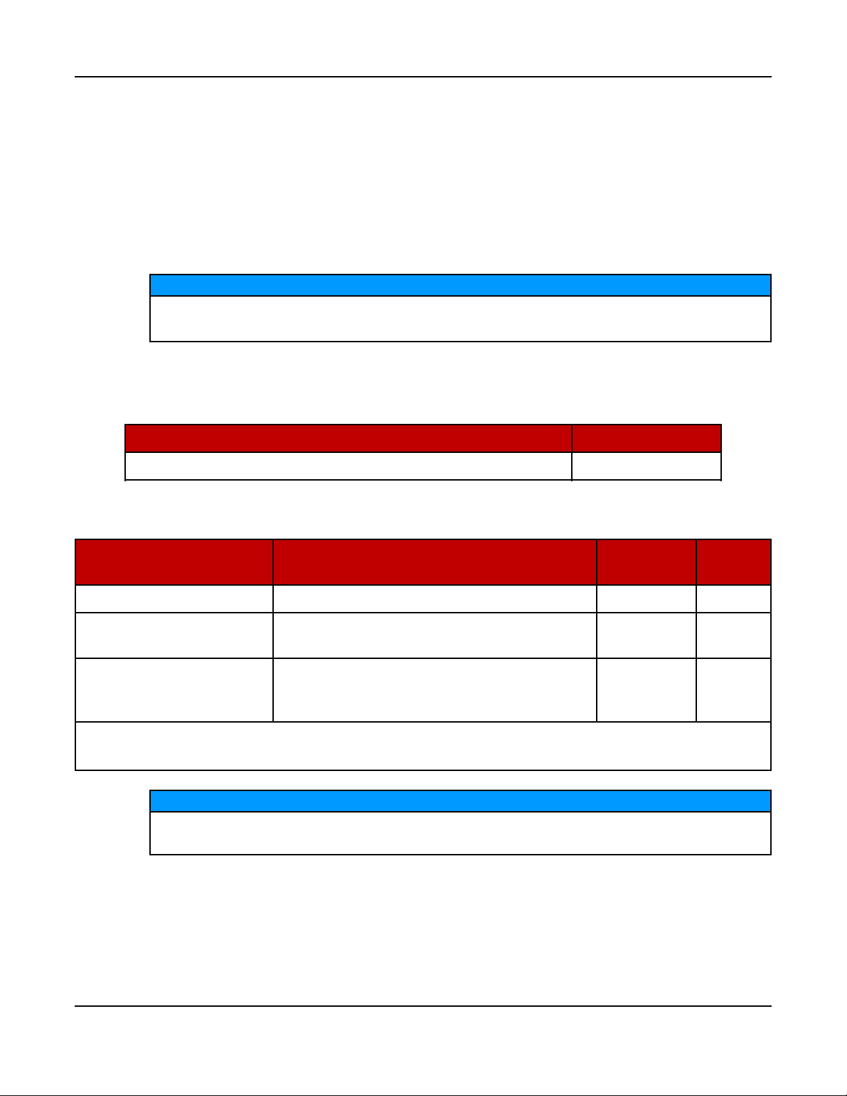
2.5 Model Specifications
Damage caused by failure to follow the manufacturer's recommendation will
not be covered by the warranty. Please contact your authorized distributor.
TABLE 1. 5.9L MODEL VARIATIONS
Models Description
2. Introduction8-2017
NOTICE
C45 N6, C50 N6, C60 N6, C70 N6, C80 N6, C100 N6 60 Hz, 1800 RPM
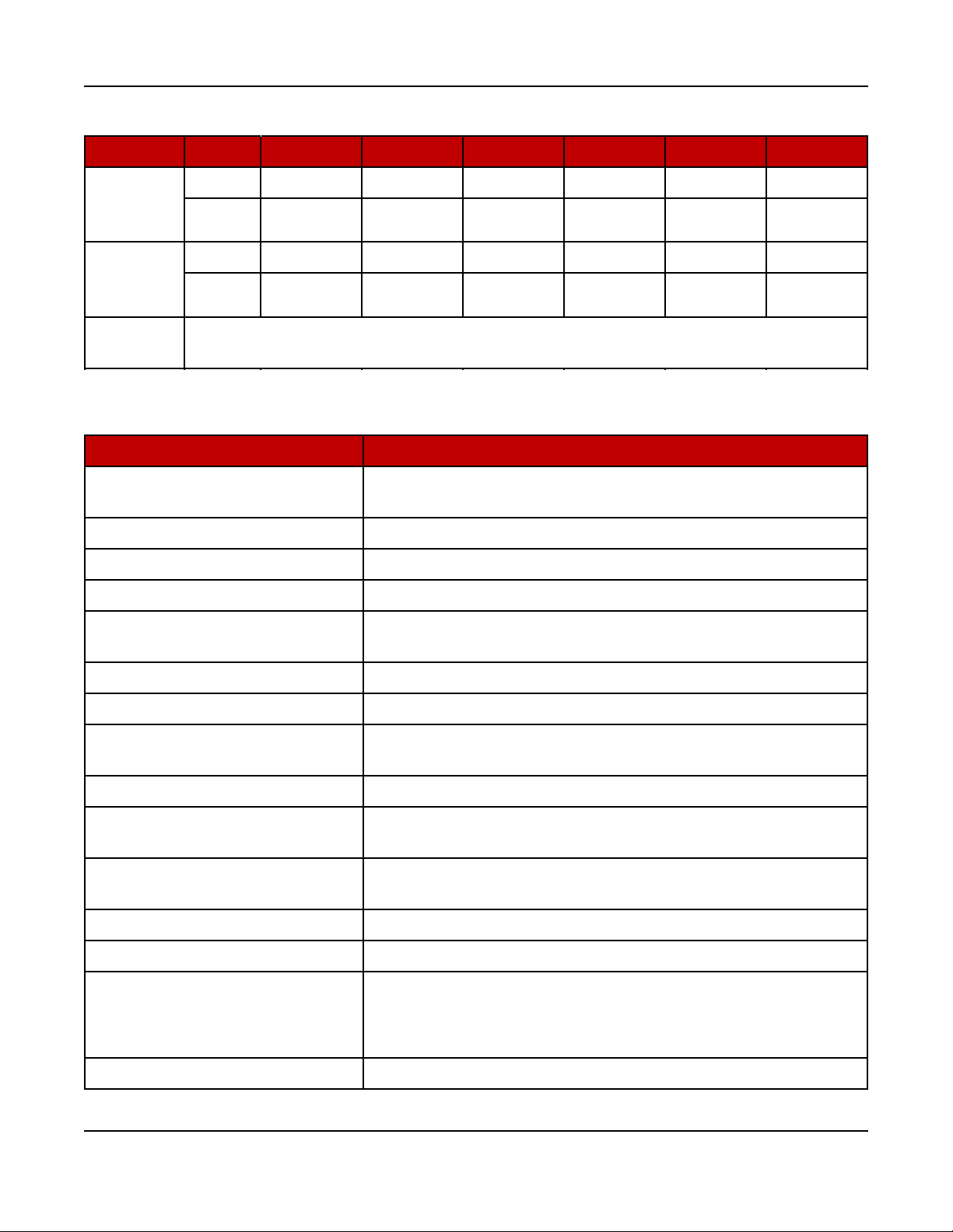
TABLE 2. COLD WEATHER SPECIFICATIONS (ALL MODELS)
Temperature Description
Battery
Type
Group
Above 4 °C (40 °F) Battery charger Standard 34
-17 to 4 °C (0 to 40 °F)
Battery charger, coolant heater (1000W),
CCV heater
1
Standard 34
Battery charger, coolant heater (1500W),
Below -17 °C (0 °F)
1
CCV heaters are provided as part of the cold and extreme cold coolant heater packages.
2
The cold weather starter is provided as part of the extreme cold coolant heater package.
oil heater, battery heater, CCV heater1,
cold weather starter
2
NOTICE
Larger 4D
For NFPA 110 applications, a coolant heater is required. A factory option is
available.
15A051X877 (Issue 6) Copyright © 2017 Cummins Inc.
Page 20
2. Introduction 8-2017
TABLE 3. FUEL SPECIFICATIONS 60 HZ, 1800 RPM
Type Unit C45 N6 C50 N6 C60 N6 C70 N6 C80 N6 C100 N6
Liquid
Propane
scfh 289.6 321.6 370.2 384.2 420.8 518.7
BTU/hr 651,600 723,600 832,950 864,450 946,800 1,167,075
Full Load
Natural
Gas
scfh 711.2 806.3 933.8 988.4 1,083.5 1,317.7
BTU/hr 721,868 818,395 947,807 1,003,226 1,099,753 1,337,466
Full Load
Fuel
6-13 inches of water column (1.5 - 3.2 kPa) under any condition
Pressure
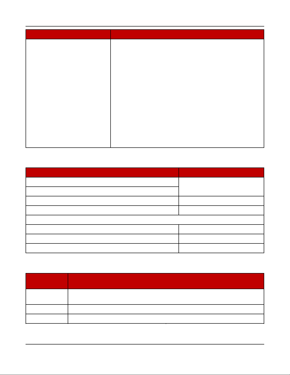
TABLE 4. ENGINE SPECIFICATIONS (ALL MODELS)
Type Specification
Engine
6 cylinder-in-line, single-cam, liquid-cooled, 4-stroke, spark
ignited
Bore 102 mm 94.02 in)
Stroke 120 mm (4.72 in)
Displacement 5.88 L (359 in3)
Compression Ratio (Natural
Gas & LPG)
8.5:1
Firing Order 1-5-3-6-2-4
Spark Plug Gap 45, 50, 60 kW) 0.508 mm (0.020 in)
Spark Plug Gap (70, 80, 100
kW)
0.40 mm (016 in)
Spark Plug Torque 38 Nm (8 ft-lb)
Crankshaft Rotation (Viewed
from the Front of the Engine)
Engine Weight (Dry, Long Block
Only)
Clockwise
413 kg (911 lb)
Valve Clearance (Intake) 0.305 mm (0.012 in)
Valve Clearance (Exhaust) 0.610 mm (0.024 in)
• 50/50 coolant solution (50% pure water and 50% anti-
Coolant
freeze)
• 16 L (4.23 gal) capacity
Oil Capacity 15 L (4 gal)
16 A051X877 (Issue 6)Copyright © 2017 Cummins Inc.
Page 21
Oil Standards
2. Introduction8-2017
Type Specification
• Must adhere to Cummins®Engineering Standard
(CES) 20085
• Use of improper oils can result in engine damage. Use
only the required oils:
◦ 5W-40 (all ambient temperatures)
◦ 15W-40 (above 4 °C [40 °F] ambient temperature)
(use of GEO 15W-40 oil in ambient temperatures
below 4 °C (40 °F] could result in engine
turbocharger damage)
• A sulfated ash limit of 0.6% mass has been placed on
all engine lubricating oils recommended for use in
Cummins® B, natural gas engines. Higher ash oils can
cause valve and/or piston damage, cause spark plug
fouling, and lead to excessive oil consumption and
degradation of the catalyst.
TABLE 5. LUBRICATING OIL SYSTEM SPECIFICATIONS
Type Specification
Lubricating Oil Pressure at Idle (Minimum) 104 kPa (15 psi)
Lubricating Oil Pressure at Rated Speed (Minimum)
Filter Bypass Valve-Opening Pressure 311 kPa (45 psi)
Pressure Regulator Valve-Opening Pressure 449 kPa (65 psi)
Lubricating Oil Capacity (Standard Sump):
--High 14.2 L (15 qt)
--Low 12.4 L (13 qt)
--Total System 15.1 L (16 qt)
TABLE 6. GENERATOR SET SIZE SPECIFICATIONS
Enclosure
Type
Open/Weather
2489 x 1016 x 1473 mm (98 x 40 x 58 in); does not include exhaust
Size (L x W x H)
discharge elbow
Sound Level 1 3023 x 1016 x 1473 mm (119 x 40 x 58 in)
Sound Level 2 3454 x 1016 x 1473 mm (136 x 40 x 58 in)
17A051X877 (Issue 6) Copyright © 2017 Cummins Inc.
Page 22
2. Introduction 8-2017
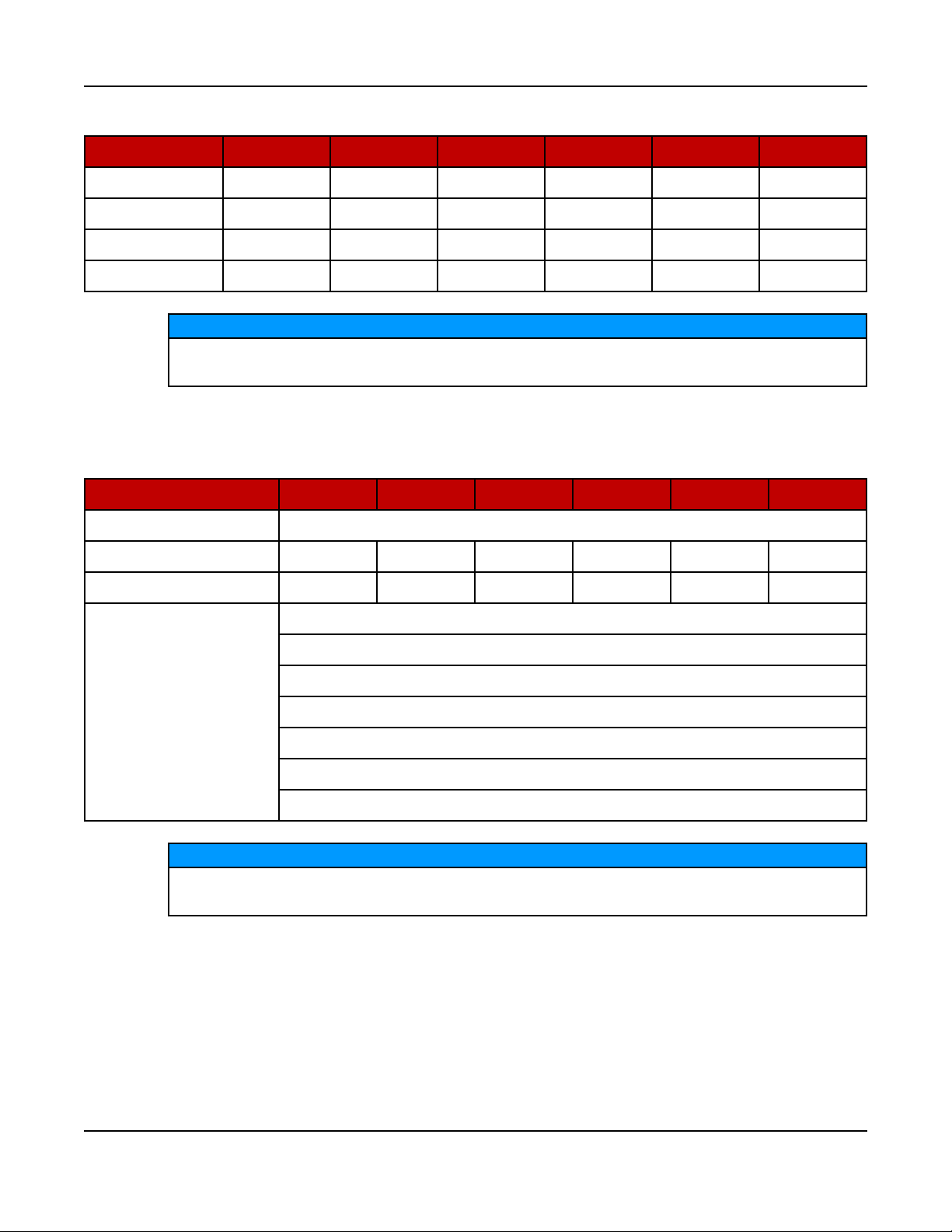
TABLE 7. GENERATOR SET WET WEIGHT (POUNDS) (60 HZ, 1800 RPM)
Configuration C45 N6 C50 N6 C60 N6 C70 N6 C80 N6 C100 N6
Open 2180 2180 2431 2449 2587 2719
Weather 2359 2359 2610 2628 2766 2898
Sound Level 1 2455 2455 2706 2724 2862 2994
Sound Level 2 2485 2485 2736 2754 2892 3024
NOTICE
Weights are approximate and can be affected by selected options. Refer to
outline drawings for specific weight information.
TABLE 8. ALTERNATOR SPECIFICATIONS 60 HZ, 1800 RPM
Type C45 N6 C50 N6 C60 N6 C70 N6 C80 N6 C100 N6
Generator Brushless, 4-pole rotating field, single bearing
Power (kVA) 1 Phase 45 50 60 70 80 100
Power (kVA) 3 Phase 56.3 62.5 75 87.5 100 125
120/240, 1 Ph
227/480, 3 Ph
347/600, 3 Ph
Rated Voltages (V)
120/240, 3 Ph
120/208, 3 Ph
127/220, 3 Ph
F1PO (Reconnectable, Full Single Phase Output)
NOTICE
Maximum I2= 8%. Generator set load unbalance must not exceed 25%
between any phases.
18 A051X877 (Issue 6)Copyright © 2017 Cummins Inc.
Page 23
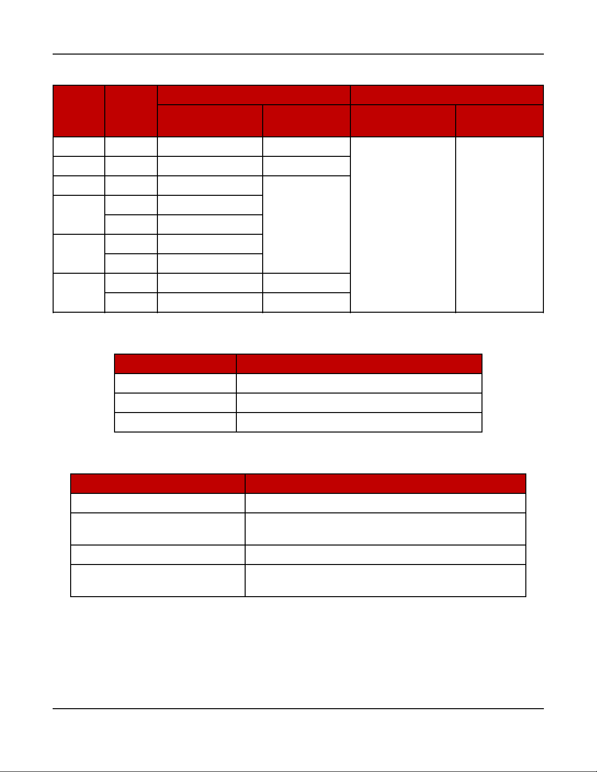
TABLE 9. GENERATOR SET DERATING GUIDELINES
Engine Power Available Up To... Derate At…
Model Phase
Elevation
C45 N6 Both 675 m (2200 ft) 40 °C (104 °F)
C50 N6 Both 150 m (490 ft) 25 °C (77 °F)
C60 N6 Both 1000 m (3280 ft)
Ambient
Temperature
2. Introduction8-2017
Elevation Temperature
C70 N6
C80 N6
C100 N6
1 2575 m (8450 ft)
3 3048 m (10000 ft)
1 1825 m (5985 ft)
3 2500 m (8200 ft)
1 700 m (1560 ft) 25 °C (77 °F)
3 1000 m (3280 ft) 40 °C (104 °F)
TABLE 10. CONTROL SPECIFICATIONS (ALL MODELS)
Control Purpose
PC 1.1 Generator Set
Enovations I28 EPR Engine (45, 50, 60 kW Generator Sets)
Enovations 4G LDI Engine (70, 80, 100 kW Generator Sets)
TABLE 11. DC SYSTEM SPECIFICATIONS (ALL MODELS)
Type Specification
40 °C (104 °F)
per 300 m (985 ft)
4%
2%
per 10 °C (18
°F)
Nominal Battery Voltage 12 VDC
Battery Group
Battery Type Maintenance-free
Minimum Cold Crank Amps
34 standard, 4D high capacity (requires large battery
tray)
850 standard, 1080 high capacity (requires large
battery tray)
2.6 After Sales Services
Cummins offers a full range of maintenance and warranty services.
19A051X877 (Issue 6) Copyright © 2017 Cummins Inc.
Page 24

2. Introduction 8-2017
Maintenance
WARNING
Electrical Generating Equipment
Incorrect service or parts replacement can result in severe personal injury,
death, and/or equipment damage.
Make sure service personnel are qualified to perform electrical and
mechanical service.
For expert generator set service at regular intervals, contact your Cummins Inc.
service provider. See power.cummins.com/sales-service-locator for service
locations that service this application. Maintenance tasks should only be undertaken
by trained and experienced technicians provided by your Cummins Inc. service
provider.
Warranty
For details of the warranty coverage for your generator set, refer to the Warranty
Statement listed in the Related Literature section.
Extended warranty coverage is also available. In the event of a breakdown, prompt
assistance can normally be given by factory trained service technicians with
facilities to undertake all minor and many major repairs to equipment on site.
For further warranty details, contact your authorized dealer.
NOTICE
Damage caused by failure to follow the manufacturer's recommendations
will not be covered by the warranty. Please contact your authorized dealer.
Warranty Limitations
For details of the warranty limitations for your generator set, refer to the
warranty statement applicable to the generator set.
How to Obtain Service
For parts, service, and product information, contact the nearest authorized Cummins
Inc. dealer. To easily locate the nearest certified distributor/dealer for Cummins
generator sets in your area, or for more information, contact us at 1-800CUMMINSTM(1-800-286-6467) or visit http://www.cummins.com/support.
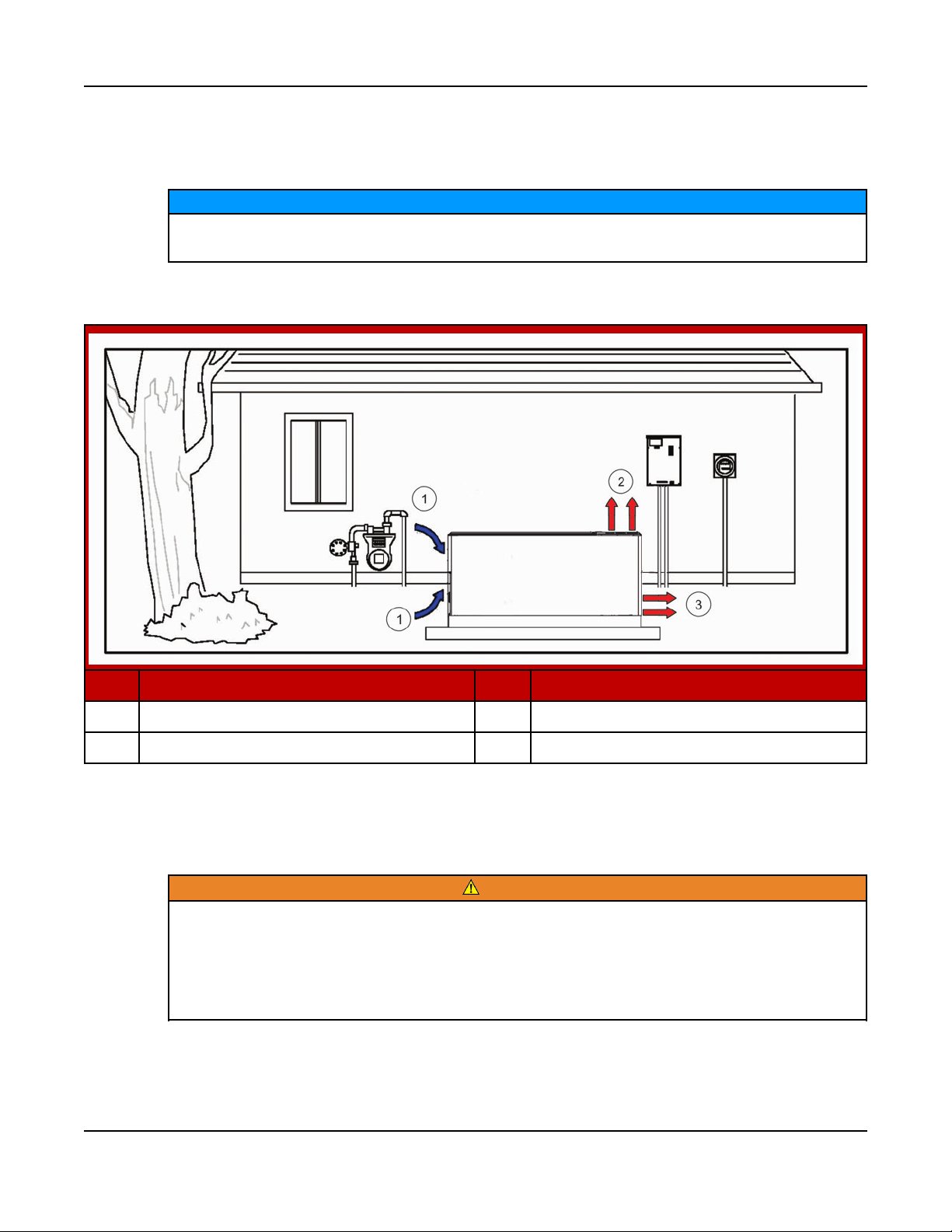
2.7 General Operating Conditions
The area surrounding the generator set is critical for safety and its performance.
Follow the guidelines below.
• Do not stack anything on top of the generator set.
20 A051X877 (Issue 6)Copyright © 2017 Cummins Inc.
Page 25
2. Introduction8-2017
• Do not store anything inside of the generator set.
• Keep areas clear in front of the cool air in and hot air out (free of obstructions,
debris, plants, etc.).
NOTICE
All maintenance procedures must be performed or supervised by authorized
and trained service personnel only.
No. Description No. Description
1 Cool Air In 3 Hot Air Out (Weather Enclosure)
2 Hot Air Out (Sound Level Enclosure)
FIGURE 1. EXAMPLE OF GENERATOR SET LOCATION
2.8 Generator Set Nameplate
WARNING
Electrical Generating Equipment
Improper service or replacement of parts can lead to severe personal injury
or death and to damage to equipment and property.
Make sure service personnel are qualified to perform electrical and
mechanical service.
21A051X877 (Issue 6) Copyright © 2017 Cummins Inc.
Page 26
2. Introduction 8-2017
NOTICE
Unauthorized modifications or replacement of fuel, exhaust, air intake or
speed control system components that affect engine emissions are
prohibited by law in the State of California.
Model, Spec, and Serial Numbers: Be ready to provide the model, spec, and
serial numbers on the generator set nameplate when contacting Cummins Inc. for
information, parts, and service. The nameplate is located on the inside of the control
access door on enclosed products or on the side of the radiator for open products.
Record these numbers so that they are easy to find when needed. Each character
in these numbers is significant for obtaining the right parts listed in the Parts
Catalog. Genuine Cummins Inc. replacement parts are recommended for best
results.
My Generator Set Information
Model
Spec
Serial
Number
22 A051X877 (Issue 6)Copyright © 2017 Cummins Inc.
Page 27

2.9 Manufacturing Facilities
Facility Address Phone Numbers
U.S. and
CANADA
Cummins Inc.
1400 73rd Ave. NE
Minneapolis, MN 55432 USA
Toll Free 1-800-CUMMINS
(1-800-286-6467)
Phone +1 763-574-5000
Fax +1 763-574-5298
2. Introduction8-2017
TM
EMEA, CIS Cummins Inc.
Columbus Avenue
Manston Park
Manston, Ramsgate
Kent CT12 5BF
United Kingdom
Cummins Inc.
Royal Oak Way South
Daventry
Northamptonshire
NN11 8NU
United Kingdom
ASIA
PACIFIC
Cummins Inc.
10 Toh Guan Road #07-01
TT International Tradepark
Singapore 608838
BRAZIL Rua Jati, 310, Cumbica
Guarulhos, SP 07180-900
Brazil
Phone +44 1843 255000
Fax +44 1843 255902
Phone +44 1843 255000
Fax +44 1843 255902
Phone +65 6417 2388
Fax +65 6417 2399
Phone +55 11 2186 4195
Fax +55 11 2186 4729
CHINA Cummins Inc.
2 Rongchang East Street,
Beijing Economic – Technological
Development Area
Beijing 100176, P.R. China
INDIA Cummins Inc.
Power Generation Business Unit,
Plot No B-2, SEZ Industrial Area,
Village-Nandal & Surwadi, Taluka- Phaltan
Dist- Satara, Maharashtra 415523
India
LATIN
AMERICA
3350 Southwest 148th Ave.
Suite 205
Miramar, FL 33027 USA
Phone 86 10 59023001
Fax +86 10 5902 3199
Phone
+91 021 66305514
Phone +1 954 431 551
Fax +1 954 433 5797
23A051X877 (Issue 6) Copyright © 2017 Cummins Inc.
Page 28

2. Introduction 8-2017
Facility Address Phone Numbers
MEXICO Eje 122 No. 200 Zona Industrial
San Luis Potosi, S.L.P. 78395
Mexico
Phone +52 444 870 6700
Fax +52 444 824 0082
24 A051X877 (Issue 6)Copyright © 2017 Cummins Inc.
Page 29

3 Control System
3.1 Control System Description
The control system is used to start and stop the generator set, and provides full
generator set monitoring capability and protection in a stand-alone situation (nonparalleling) from the display screen. It monitors the engine for temperature, as well
as oil pressure and speed. It also provides voltage and current metering. In the
event of a fault, the unit indicates the fault type and, on critical faults, automatically
shuts down the generator set.
All indicators, control buttons, and the display screen are on the face of the operator
panel, as illustrated in the figure below.
There are three fault level signals generated by the control system:
• Event: Signals that a temporary condition exists.
• Warning: Signals an imminent or non-critical fault for the engine. The control
provides an indication only for this condition.
• Shutdown: Signals a potentially critical fault for the engine. The control
immediately takes the engine off-load and automatically shuts it down.
The standard control system operates on 12 VDC (or 24 VDC if applicable) battery
power. History data is stored in non-volatile memory and is not deleted if battery
power is lost.
Standard Operator Panel
The operator panel includes indicator lights (LEDs), display buttons used to
navigate through the menus, control mode buttons, and an LCD display. The display
enables the operator to check the status, adjust the settings, and start and stop the
generator set. The standard operator panel (show below) is located on every
generator set. An optional in-home operator panel accessory is also available for
location inside the home.
25A051X877 (Issue 6) Copyright © 2017 Cummins Inc.
Page 30

3. Control System 8-2017
FIGURE 2. STANDARD OPERATOR PANEL (HMI211)
Standard Key Functions (HMI211)
The user interface includes two fixed action buttons and four soft key buttons.
The action of the soft key buttons changes to meet the requirements of each
screen.
TABLE 12. KEY FUNCTIONS
Key/Symbol Action
Switches to Off mode (fixed action button).
Switches to Auto mode.
Switches to Manual Run mode.
Navigates to the previous menu level (fixed action button).
(Up Arrow) Navigates to the previous screen/menu in a list.
(Down Arrow) Navigates to the next screen/menu in a list.
and Hold the up and down arrows simultaneously for two seconds from any
Info Menu to navigate to the Menu screen.
Save Saves changes and navigates to the associated screen.
Adjust Navigates to the Adjust Menu of a specific menu.
(Right Arrow) Advances the highlighted field to the next editable field.
26 A051X877 (Issue 6)Copyright © 2017 Cummins Inc.
Page 31

Key/Symbol Action
- Decreases value of the highlighted editable field.
+ Increases value of highlighted editable field.
Standard LED Indicators (HMI211)
The operator panel has six LED indicators. Colors, flashing frequency, and
conditions to turn them on/off/blink are included in the table below.
TABLE 13. LED INDICATORS
LED Color Action
Not in Auto Red Indicates the generator set is in Manual or Off Mode.
Shutdown Red Indicates a Shutdown Fault has occurred.
Warning Yellow Indicates a Warning Fault has occurred.
3. Control System8-2017
Remote
Start
Auto Green Indicates that the generator set is in Auto Mode. The generator starts
Manual Run Green Indicates that the generator set has received a Manual Run
Green Indicates that the generator set has received a Remote Start
Command.
when it receives a Remote Start Command.
Command.
In-Home Operator Panel (Accessory)
The in-home operator panel is an optional display that may be purchased. This
panel is intended to serve as a convenience option to the standard operator panel
mounted on the generator set.
27A051X877 (Issue 6) Copyright © 2017 Cummins Inc.
Page 32

3. Control System 8-2017
FIGURE 3. IN-HOME OPERATOR PANEL
Key Functions (In-Home Operator Panel)
The user interface includes two fixed action buttons and four soft key buttons.
The action of the soft key buttons changes to meet the requirements of each
screen.
TABLE 14. KEY FUNCTIONS
Key/Symbol Action
Stop Switches to Off mode. This key works from any screen (fixed action
button).
(Up Arrow) Navigates to the previous screen/menu in a list.
(Down Arrow) Navigates to the next screen/menu in a list.
and Hold the up and down arrows simultaneously for two seconds from any Info
Menu to navigate to the Service Menu.
Back Navigates to the previous screen/menu in a list (fixed action button). In
Adjust screens, settings are not saved.
Save Saves changes and navigates to the associated screen.
Adjust Navigates to the Adjust Menu of a specific menu.
(Right Arrow) Advances the highlighted field to the next editable field.
- Decreases value of the highlighted editable field.
+ Increases value of highlighted editable field.
28 A051X877 (Issue 6)Copyright © 2017 Cummins Inc.
Page 33

3. Control System8-2017
LED Indicators (In-Home Operator Panel)
The operator panel has five LED indicators. Colors, flashing frequency, and
conditions to turn them on/off/blink are included in the table below.
TABLE 15. LED INDICATORS
LED Color Action
Shutdown Red Indicates a Shutdown Fault has occurred.
Warning Yellow Indicates a Warning Fault has occurred.
Auto Start Green Indicates that the generator set has received a Remote Start
Command.
Auto Green Indicates that the generator set is in Auto Mode. The
generator starts when it receives a Remote Start Command.
Manual Run Green Indicates that the generator set has received a Manual Run
Command.
3.2 Display Text or Symbolic Version
The operator panel graphical display can be set to show text (English only) or
symbols for fault messages, operator menus, and the Mode Change Menu.
Descriptions of commonly used symbols are included in the following table.
Combinations of symbols are used to display some fault conditions.
When shipped from the factory, the display is set to display symbols. Qualified
service personnel are required to change the default setting.
TABLE 16. SYMBOLS
Symbol Text
Generator Warning Fault
Generator Shutdown Fault
Coolant Temperature
Oil Pressure
Voltage Alternating Current (VAC)
Voltage Direct Current (VDC)
AC Current
Hz Frequency
29A051X877 (Issue 6) Copyright © 2017 Cummins Inc.
Page 34

3. Control System 8-2017
Symbol Text
Battery
Out of Range
High or Pre-High
Low or Pre-Low
Annunciator
Over Speed
Crank Fail
Emergency Stop
3.3 Exercise Settings
When battery power is lost, these settings must be reset.
Not applicable without an RA series transfer switch.
To access the Clock/Exerciser Menu:
1. From any Information Menu, hold down the up and down arrows simultaneously
for two seconds. The Service Menu appears.
2. Navigate through the screens to find and select Clock/Excr in the Service
Menu.
The following screens represent the standard operator panel (that is,
HMI211). If using an in-home operator panel, which may be additionally
purchased as an option, the screens may look slightly different. This
procedure applies to both operator panels.
NOTICE
NOTICE
NOTICE
30 A051X877 (Issue 6)Copyright © 2017 Cummins Inc.
Page 35

3. Control System8-2017
FIGURE 4. CLOCK/EXERCISER MENU NAVIGATION
31A051X877 (Issue 6) Copyright © 2017 Cummins Inc.
Page 36

3. Control System 8-2017
Updating Exercise Frequency (3-Phase ATS)
NOTICE
Not applicable without an RA series transfer switch.
To update the exercise frequency and dates on the Clock/Exerciser Menu:
1. From any Information Menu, hold down the up and down arrows simultaneously
for two seconds. The Service Menu appears.
2. Access the Time Setup screen by selecting Clock Exerciser on the Genset
Service Menu.
3. Press the down key on the Time Setup screen to access the Daylight Saving
Adjust screen.
4. Select Adjust.
5. Press the down key on the Daylight Saving Adjust Start screen.
6. Select Adjust.
7. Press Exercise Schdr on the Daylight Saving Adjust End screen.
8. Press Adjust.
When updating these settings, the functions of the keys are as follows:
• The horizontal right arrow key is used to select successive blocks for editing
settings on the screen.
• Use the + or - keys to edit the following settings:
◦ Schdr Enable: Enable or Disable
◦ Exercise Schedule: Semi-Annual (every six months), Quarterly, Monthly,
Bi-Weekly (every two weeks) , or Weekly
◦ Exercise Schedule: Day, Hours, Minutes, AM/PM
• Press Save to save any changes. After saving, the Save button changes to the
Adjust button.
32 A051X877 (Issue 6)Copyright © 2017 Cummins Inc.
Page 37

FIGURE 5. EXERCISE FREQUENCY NAVIGATION
3. Control System8-2017
Updating Exercise Duration (3-Phase ATS)
NOTICE
Not applicable without an RA series transfer switch.
To update the exercise duration on the Clock/Exerciser Menu:
1. From any Information Menu, hold down the up and down arrows simultaneously
for two seconds. The Service Menu appears.
2. Access the Time Setup screen by selecting Clock Exerciser on the Genset
Service Menu.
3. Press the down key on the Time Setup screen to access the Daylight Saving
Adjust screen.
4. Select Adjust.
5. Press the down key on the Daylight Saving Adjust Start screen.
6. Select Adjust.
7. Press Exercise Schdr on the Daylight Saving Adjust End screen.
8. Press the down key on the Exercise Schdr Menu.
9. Press Adjust.
When updating these settings, the functions of the keys are as follows:
• The horizontal right arrow key is used to select the duration block for editing
exercise duration.
• Use the + or - keys to edit the exercise duration minutes.
33A051X877 (Issue 6) Copyright © 2017 Cummins Inc.
Page 38

3. Control System 8-2017
• Press Save to save any changes. After saving, the Save button changes to the
Adjust button.
FIGURE 6. EXERCISE DURATION NAVIGATION
Time Setup (3-Phase ATS)
NOTICE
When battery power is lost, these settings must be reset.
NOTICE
Not applicable without an RA series transfer switch.
To set up the generator set clock for the current date and time:
1. From any Information Menu, hold down the up and down arrows simultaneously
for two seconds. The Service Menu appears.
2. Access the Time Setup screen by selecting Clock Exerciser on the Genset
Service Menu.
3. Select Adjust.
When updating these settings, the functions of the keys are as follows:
• The horizontal right arrow key is used to select successive blocks for editing
settings on the screen.
• Select the left arrow to return to the previous screen.
• Adjust values by using the + or - keys on the Adjust Menu of the Time Setup
screen.
• Press Save to save any changes. After saving, the Save button changes to the
Adjust button.
34 A051X877 (Issue 6)Copyright © 2017 Cummins Inc.
Page 39

FIGURE 7. TIME SETUP SCREEN
Updating Daylight Saving Adjust Screens
3. Control System8-2017
Update Values on the Daylight Saving Adjust Screen
1. From any Information Menu, hold down the up and down arrows
simultaneously for two seconds. The Service Menu appears.
2. Navigate to the Genset Service Menu.
3. Select Clock Exerciser to access the Time Setup screen.
4. Press the down key on the Time Setup screen to access the Daylight
Saving Adjust screen.
5. Select Adjust. When updating these settings, the functions of the keys
are as follows:
TABLE 17. KEY FUNCTIONS ON THE DAYLIGHT SAVING ADJUST SCREEN
Key/Button Function
Horizontal right arrow key Select successive blocks for editing settings on the screen
Left arrow key Return to the previous screen
+ or - keys Adjust values on the Adjust screen of the Daylight Saving Adjust
screen
Save button Save any changes; after saving, the Save button changes to the
Adjust button
35A051X877 (Issue 6) Copyright © 2017 Cummins Inc.
Page 40

3. Control System 8-2017
FIGURE 8. "DAYLIGHT SAVING ADJUST SAVING TIME" SCREEN NAVIGATION
Access and Update the Daylight Saving Adjust Start Screen
1. Press the down arrow key on the Daylight Saving Adjust screen.
2. Press Adjust. When updating these settings, the functions of the keys are
as follows:
TABLE 18. KEY FUNCTIONS ON THE DAYLIGHT SAVING ADJUST START SCREEN
Key/Button Function
Horizontal right arrow key Select successive blocks for editing settings on the screen
+ or - keys Adjust Month, Week, Day or Hour
Save button Save any changes; after saving, the Save button changes to the
Adjust button
36 A051X877 (Issue 6)Copyright © 2017 Cummins Inc.
Page 41

FIGURE 9. DAYLIGHT SAVING ADJUST START SCREEN
3. Control System8-2017
Update the Daylight Saving Adjust End Screen
1. Press the down key on the Daylight Saving Adjust Start screen.
2. Press Adjust. When updating these settings, the functions of the keys are
as follows:
TABLE 19. KEY FUNCTIONS ON THE DAYLIGHT SAVING ADJUST END SCREEN
Key/Button Function
Horizontal right arrow key Select successive blocks for editing settings on the screen
+ or - keys Adjust Month, Week, Day or Hour
Save button Save any changes; after saving, the Save button changes to the
Adjust button
37A051X877 (Issue 6) Copyright © 2017 Cummins Inc.
Page 42

3. Control System 8-2017
FIGURE 10. DAYLIGHT SAVING ADJUST END SCREEN
3.4 Brightness and Contrast
The Screen Adjust screen allows the contrast, brightness, and units to be set. To
access the Screen Adjust screen:
1. From any Information screen, hold down the up and down arrows
simultaneously for two seconds to gain access to the Service Menu screen.
2. Select Screen Adjust.
To adjust the contrast, brightness, or units from the Screen Adjust screen:
1. From the Screen Adjust screen, select Adjust to access the screen variables.
2. Press the right arrow to move between the variables.
3. Adjust settings, and press Save to save any changes.
When updating these settings, the functions of the keys are as follows:
• The horizontal right arrow key is used to select successive blocks for editing
settings on the screen.
• Select the left arrow to return to the previous screen.
• Adjust values by using the + or - keys on the Adjust screen of the Display
Setup screen.
• Press Save to save any changes. After saving, the Save button changes to the
Adjust button.
38 A051X877 (Issue 6)Copyright © 2017 Cummins Inc.
Page 43

3. Control System8-2017
NOTICE
The following screens represent the standard operator panel (HMI211). If
using an in-home operator panel, which may be additionally purchased as an
option, the screens may look slightly different. This procedure applies to
both operator panels.
FIGURE 11. BRIGHTNESS AND CONTRAST SCREEN NAVIGATION
39A051X877 (Issue 6) Copyright © 2017 Cummins Inc.
Page 44

3. Control System 8-2017
NOTICE
Adjusting the brightness on the operator panel adjusts the brightness of
both the LCD backlight and the LEDs on the display. The contrast should
never be 0 or 100% on any of the screens. The default value for Brightness is
50%.
3.5 History and About Menu
To access the History/About screen:
1. From any Information Menu, hold down the up and down arrows simultaneously
for two seconds. The Service Menu appears.
2. Select History/About.
3. Advance through the screens to view information about the generator set,
control, and display.
NOTICE
The following screens represent the standard operator panel (HMI211). If
using an in-home operator panel, which may be additionally purchased as an
option, the screens may look slightly different. This procedure applies to
both operator panels.
40 A051X877 (Issue 6)Copyright © 2017 Cummins Inc.
Page 45

3. Control System8-2017
FIGURE 12. HISTORY/ABOUT MENU
41A051X877 (Issue 6) Copyright © 2017 Cummins Inc.
Page 46

3. Control System 8-2017
3.6 Fault Log
To check the fault log:
1. From any Information Menu, hold down the up and down arrows simultaneously
for two seconds. The Service Menu appears.
2. Select Fault History.
NOTICE
The active faults are displayed first. If there are no active faults, this screen
is skipped. Following the Active Faults screen are the Fault History screens.
These screens display the faults in chronological order from newest to
oldest.
NOTICE
The following screens represent the standard operator panel (HMI211). If
using an in-home operator panel, which may be additionally purchased as an
option, the screens may look slightly different. This procedure applies to
both operator panels.
42 A051X877 (Issue 6)Copyright © 2017 Cummins Inc.
Page 47

3. Control System8-2017
FIGURE 13. FAULT LOG SCREEN
43A051X877 (Issue 6) Copyright © 2017 Cummins Inc.
Page 48

3. Control System 8-2017
3.7 Selecting Operating Modes
Selecting Manual Run Mode
WARNING
Electrical Generating Equipment
When changing modes, the generator set can start or stop without warning
(for example, Auto Mode may have been selected with no mains (utility)
power available).
Make sure there is no danger to personnel or equipment, if the generator set
starts or stops when changing modes.
1. Before proceeding to change the mode, make sure that it is safe to do so.
2. Press the Manual Run button on any of the Operator menus or the
"Establishing/Re-establishing communication with control" menus.
3. If the Mode Change Access Code menu is enabled, the Mode Change Access
Code is displayed. Enter the Mode Change Access Code.
4. A menu with alternating arrows is displayed above a second symbol.
5. Press the second Manual Run button, and the generator set will now begin
the Manual start sequence. The Operator menu that was displayed before
Manual Run mode was selected is re-displayed, but with the symbol blacked
out.
NOTICE
To disable Manual Run mode, press the Off button.
NOTICE
Auto mode can also be selected while in Manual Run mode. Switching to
Auto mode may result in the generator set shutting down.
44 A051X877 (Issue 6)Copyright © 2017 Cummins Inc.
Page 49

3. Control System8-2017
No. Description No. Description
1 Menu Displayed Only When the Mode
3 Manual Run Mode Selected
Change Access Code Feature Is
Enabled
2 Alternating Arrows Displayed
FIGURE 14. SELECTING MANUAL RUN MODE
45A051X877 (Issue 6) Copyright © 2017 Cummins Inc.
Page 50

3. Control System 8-2017
Selecting Auto Mode
WARNING
Electrical Generating Equipment
When changing modes, the generator set can start or stop without warning
(for example, Auto Mode may have been selected with no mains (utility)
power available).
Make sure there is no danger to personnel or equipment, if the generator set
starts or stops when changing modes.
To switch to Auto mode (see Figure 15 on page 47),
1. Ensure that it is safe to do so before proceeding to change the mode.
2. Press the Auto button on any of the Operator menus, or the
‘Establishing/Re-establishing communication with control’ menus.
3. If the mode change access code feature is enabled, the Mode Change Access
Code menu is displayed. Enter the Mode Change Access Code.
4. A menu with alternating arrows will then be displayed above a second
Auto symbol.
5. Press this second Auto button. The Operator menu that was displayed
before Auto mode was selected is re-displayed, but with the Auto symbols
blacked out and Manual Run symbols visible.
To disable Auto mode, press the Off button.
The generator set is now ready to receive a remote start signal that will initiate the
Auto run mode.
WARNING
Should a remote start signal be received, the generator set starts
automatically. Make sure there is no danger to personnel or equipment
should the generator set start without warning.
NOTICE
Manual Run mode can also be selected FROM Auto mode. Switching to
Manual Run mode results in the generator set starting up.
46 A051X877 (Issue 6)Copyright © 2017 Cummins Inc.
Page 51

3. Control System8-2017
No. Description No. Description
1 This Menu Is Displayed Only if the
3 Auto Mode Selected
Mode Change Access Code Feature Is
Enabled
2 Alternating Arrows Are Displayed
FIGURE 15. SELECTING AUTO MODE
47A051X877 (Issue 6) Copyright © 2017 Cummins Inc.
Page 52

3. Control System 8-2017
Selecting Off Mode
WARNING
Electrical Generating Equipment
When changing modes, the generator set can start or stop without warning
(for example, Auto Mode may have been selected with no mains (utility)
power available).
Make sure there is no danger to personnel or equipment, if the generator set
starts or stops when changing modes.
To switch to Off mode (see the figure below),
1. Make sure that it is safe to do so before proceeding to stop the set.
2. Press the Off button on any of the Operator menus or the "Establishing/Reestablishing communication with control" menus.
3. If the Mode Change Access Code is enabled, the Mode Change Access Code
will be displayed. Enter the Mode Change Access Code.
4. On entering the last correct digit, the basic screen will re-appear, and the set
will stop without a Time Delay to Stop.
NOTICE
Make sure that there is no danger to personnel or equipment if the
generator set is stopped.
48 A051X877 (Issue 6)Copyright © 2017 Cummins Inc.
Page 53

3. Control System8-2017
No. Description No. Description
1 Off Button 2 This Mode Is Displayed Only if the
Mode Change Access Code Feature Is
Enabled
FIGURE 16. SELECTING OFF MODE
3.8 Operating Modes
The generator set's PowerCommand®control has Manual Run, Off, and Auto
operating modes that are available from the operator panel.
49A051X877 (Issue 6) Copyright © 2017 Cummins Inc.
Page 54

3. Control System 8-2017
Off Mode
When in Off mode, the control does not allow the generator set to start. If the
generator set is already running and the control is set to Off, it initiates a normal
shutdown sequence.
Manual Run Mode
When in Manual Run mode, the generator set starts and continues to run until the
control is put into the Off mode. While in Manual Run mode, the remote start signal
is ignored.
Auto Mode
When in Auto mode, the control allows the generator set to be started with a remote
start signal only.
When in Auto mode, the generator set can start at any time. When a remote start
signal is received, the genset starts after a time delay preheat (if programmed) and
time delay start (if programmed) is completed.
If the generator set is running in Auto mode and the Off button is pressed, the
control immediately stops the genset and the control transitions to the Off mode.
When all remote start signals are removed, the control performs a normal shutdown
sequence which may include a time delay stop.
50 A051X877 (Issue 6)Copyright © 2017 Cummins Inc.
Page 55

4 Operation - PowerCommand 1.1
4.1 Introduction
This section describes the operation of the generator set. The text should be read in
conjunction with the Control System section of this manual.
All indicators, control switches/buttons, and graphical display are located on the
face of the Operator Panel.
4.2 General Operating Conditions
The area surrounding the generator set is critical for safety and its performance.
Follow the guidelines below.
• Do not stack anything on top of the generator set.
• Do not store anything inside of the generator set.
• Keep areas clear in front of the cool air in and hot air out (free of obstructions,
debris, plants, etc.).
NOTICE
All maintenance procedures must be performed or supervised by authorized
and trained service personnel only.
4.3 Generator Set Operation
WARNING
Combustible Vapors
Do not operate an engine where there are or can be combustible vapors.
These vapors can be sucked through the air intake system and cause engine
acceleration and overspeeding, which can result in a fire, an explosion,
personal injury and extensive property damage.
Correct care of your engine will result in longer life, better performance, and more
economical operation.
Cummins Inc. does not know how you will use your generator set. The equipment
owner and operator, therefore, is responsible for safe operation in the installation
site environment. Consult your authorized Cummins dealer for further information.
51A051X877 (Issue 6) Copyright © 2017 Cummins Inc.
Page 56

4. Operation - PowerCommand 1.1 8-2017
NOTICE
Diesel engines only: Cummins Inc. recommends the installation of an air
intake shutoff device or a similar safety device to minimize the risk of
overspeeding where an engine will be operated in a combustible
environment.
NOTICE
Long periods of idling (more than ten minutes) can damage an engine. Do
not idle the engine for excessively long periods.
Sequence of Operation
NOTICE
The following sequences are based on an approximate time duration. Your
generator set may vary slightly from the timing diagrams in this manual. All
referenced times are based on default control settings. The following
sequences are applicable to generator sets connected to an RA series
transfer switch.
Power Outage Sequence
The sequence of operation after a power outage (when the generator set is in
Auto Mode) is as follows:
1. In normal operation, the utility power is running to the transfer switch and
then to the building load, and the generator set is off.
2. The utility power turns off (power outage).
3. One second after the power outage, the transfer switch sends the
command to the generator set to start.
4. If the ambient temperature is below 20 °F/-6.7 °C, the generator set will
idle at 800 rpm for up to 2 minutes to allow sufficient turbo lubrication.
• The set points are 20 °F/-6.7 °C and below, ramping linearly from 0
sec (20 °F/-6.7 °C) to 2 minutes (-40 ° F/-40 °C) and held constant at
2 minutes if below -40 °F/-40 °C.
FIGURE 17. COLD START IDLE ACTIVE
52 A051X877 (Issue 6)Copyright © 2017 Cummins Inc.
Page 57

4. Operation - PowerCommand 1.18-2017
NOTICE
The control box area is equipped with an ambient temperature
sensor for controlling the idle feature. Do not install any heaters in
the control box area as this can influence the sensor and lead to
engine damage.
5. After the generator set ramps up to rated speed, the generator set
provides voltage to the transfer switch, but the transfer switch does not
switch (allowing the voltage to go to the building) until after a delay.
FIGURE 18. TIME REMAINING UNTIL TRANSFER SCREEN
6. Five seconds after starting, the generator set provides a signal to the
transfer switch to transfer the building load to the generator set.
FIGURE 19. BUILDING LOAD TRANSFER IN PROCESS
7. The transfer switch switches the generator set power to the building load.
The building is now running on generator power.
FIGURE 20. GENERATOR SET POWERING BUILDING LOAD
8. When the utility power is back and providing voltage to the transfer
switch, the transfer switch waits for utility power stability.
53A051X877 (Issue 6) Copyright © 2017 Cummins Inc.
Page 58

4. Operation - PowerCommand 1.1 8-2017
FIGURE 21. TIME REMAINING UNTIL RE-TRANSFER
9. When the utility power is stable for 5 minutes, the transfer switch
switches back to utility power.
FIGURE 22. BUILDING LOAD TRANSFER IN PROCESS
FIGURE 23. UTILITY POWERING BUILDING LOAD
10. The generator set runs for a 5-minute cooldown and shuts off.
FIGURE 24. TIME REMAINING UNTIL STOP
11. Normal operation resumes.
Exercise Sequence
The exercise sequence when the programmed exercise time is realized (the
generator set is in Auto Mode) is as follows:
1. The generator set starts and runs.
54 A051X877 (Issue 6)Copyright © 2017 Cummins Inc.
Page 59

4. Operation - PowerCommand 1.18-2017
2. If the ambient temperature is below 20 ° F (6.7 °C), the generator set will
idle at 800 rpm for up to 2 minutes to allow sufficient turbo lubrication.
• Idle time is linear from 2 minutes at -40 °F (4 °C), or below to off at
20 °F (6.7 °C) or above.
FIGURE 25. COLD START IDLE ACTIVE
3. The Exerciser Scheduler On screen displays every 3 seconds and toggles
between the existing Information screen that is displayed for 1 second.
FIGURE 26. EXERCISER SCHEDULER SCREEN AND INFORMATION SCREEN
TOGGLE - EXAMPLE
4. The transfer switch is not commanded to switch the building load to the
generator set.
NOTICE
The user may navigate to other screens from the Information
screens during this duration. No functional keys are active on the
Exerciser Scheduler On screen.
5. The generator set stops after programmed exercise run time.
Manually Starting the Generator Set Sequence
If the generator set is manually started with the standard operator panel,
HMI211 (the generator set is in Man Mode), the sequence is as follows:
55A051X877 (Issue 6) Copyright © 2017 Cummins Inc.
Page 60

4. Operation - PowerCommand 1.1 8-2017
NOTICE
Open the generator set main line circuit breaker to prevent the transfer
switch from transferring building load to the generator set. The
generator set display will still show the RA series ATS transfer;
however, the switch will not transfer if the generator set breaker is
open.
1. In normal operation, the utility power is running to the transfer switch and
then to the building load, and the generator set is off.
2. Manually start the generator set via the standard control (HMI211)
mounted on the generator set.
FIGURE 27. MANUAL START SCREEN, STANDARD OPERATOR PANEL
3. The generator set starts.
4. If the ambient temperature is below 20 ° F (6.7 °C), the generator set will
idle at 800 rpm for up to 2 minutes to allow sufficient turbo lubrication
after which the generator will ramp up to rated speed.
• Idle time is linear from 2 minutes at -40 F (4 °C), or below to off at 20
°F (6.7 °C) or above.
56 A051X877 (Issue 6)Copyright © 2017 Cummins Inc.
Page 61

4. Operation - PowerCommand 1.18-2017
FIGURE 28. COLD START IDLE ACTIVE
5. The generator set provides voltage to the transfer switch. (However, the
transfer switch does not transfer in manual mode.)
Remote Starting the Generator Set Sequence
If the generator set is remote started with the in-home operator panel
accessory, if equipped (the generator set is in Auto Mode), the sequence is as
follows:
1. In a normal operation, the utility power is running to the transfer switch
and then to the building load, and the generator set is off.
2. The generator set-mounted control (HMI211) is set in Auto Mode.
57A051X877 (Issue 6) Copyright © 2017 Cummins Inc.
Page 62

4. Operation - PowerCommand 1.1 8-2017
FIGURE 29. HMI211 SET IN AUTO MODE
3. Manually start the generator set via the in-home operator panel.
58 A051X877 (Issue 6)Copyright © 2017 Cummins Inc.
Page 63

4. Operation - PowerCommand 1.18-2017
FIGURE 30. MANUAL START SCREEN, IN-HOME OPERATOR PANEL
4. The generator set starts and provides voltage to the transfer switch, but
the transfer switch does not switch (allowing the voltage to go to the
building) until after a delay.
FIGURE 31. TIME REMAINING UNTIL TRANSFER SCREEN
5. Five seconds after starting, the generator set provides a signal to the
transfer switch to transfer the building load to the generator set.
59A051X877 (Issue 6) Copyright © 2017 Cummins Inc.
Page 64

4. Operation - PowerCommand 1.1 8-2017
FIGURE 32. BUILDING LOAD TRANSFER IN PROCESS
6. If the ambient temperature is below 20 °F (6.7 °C) , the generator set will
idle at 800 rpm for up to 2 minutes to allow sufficient turbo lubrication.
• Idle time is linear from 2 minutes at -40 F (40 °C), or below to off at
20 °F (6.7 °C) or above.
FIGURE 33. COLD START IDLE ACTIVE
7. The transfer switch switches the generator set power to the building load.
The building is now running on generator power.
FIGURE 34. GENERATOR SET POWERING BUILDING LOAD
8. When the remote display Stop button is pressed, the transfer switch
switches back to utility power after a 5 minute retransfer delay.
FIGURE 35. BUILDING LOAD TRANSFER IN PROCESS
60 A051X877 (Issue 6)Copyright © 2017 Cummins Inc.
Page 65

4. Operation - PowerCommand 1.18-2017
FIGURE 36. UTILITY POWERING BUILDING LOAD
9. The generator set runs for a 5-minute cooldown and shuts off.
FIGURE 37. TIME REMAINING UNTIL STOP
10. Normal operation resumes.
61A051X877 (Issue 6) Copyright © 2017 Cummins Inc.
Page 66

4. Operation - PowerCommand 1.1 8-2017
This page is intentionally blank.
62 A051X877 (Issue 6)Copyright © 2017 Cummins Inc.
Page 67

5 Maintenance
5.1 Maintenance Safety
Automated Machinery
Accidental or remote starting of the generator set can cause severe personal
injury or death.
Isolate all auxiliary supplies and use an insulated wrench to disconnect the
starting battery cables (negative [–] first).
Hydrogen Gas
Arcing can ignite explosive hydrogen gas given off by batteries, causing
severe personal injury or death. Arcing can occur when cables are removed
or replaced, or when the negative (–) battery cable is connected and a tool
used to connect or disconnect the positive (+) battery cable touches the
frame or other grounded metal part of the generator set.
Insulated tools must be used when working in the vicinity of the batteries.
Always remove the negative (–) cable first and reconnect last.
WARNING
WARNING
WARNING
Explosive Fumes
Arcing can ignite explosive fumes causing severe personal injury or death.
Make sure hydrogen from the battery, engine fuel and other explosive fumes
are fully dissipated before working on the generator set.
WARNING
Working at Heights
Using the incorrect equipment when working at heights can result in severe
personal injury or death.
Suitable equipment for performing these tasks must be used in accordance
with the local guidelines and legislation. Failure to follow these instructions
can result in severe personal injury or death.
63A051X877 (Issue 6) Copyright © 2017 Cummins Inc.
Page 68

5. Maintenance 8-2017
WARNING
Access
Using the generator set or part of as a means of access when attaching
lifting shackles, chains, or other lifting aids, may damage the generator set,
causing severe personal injury or death.
Do not use the generator set as a means of access. Failure to follow these
instructions can result in severe personal injury or death.
WARNING
Exposed Terminations
Some panel internal components may have live exposed terminations even if
the generator set is not running. Voltages are present which can cause
electrical shock, resulting in personal injury or damage to equipment.
Isolate all external electrical supplies prior to access of the control panel
NOTICE
Only authorized and qualified maintenance technicians who are familiar with
the equipment and its operation should carry out maintenance.
NOTICE
Dependent upon the control system fitted, this unit may operate
automatically and could start without warning.
NOTICE
Always disconnect a battery charger from its AC source before
disconnecting the battery cables. Failure to do so can result in voltage
spikes high enough to damage the DC control circuits of the generator set.
All maintenance tasks must be performed, but be sure to assess them for health
and safety risks before starting. For example, perform a task with someone present
if doing so will add significantly to the safety of the task.
Read, understand, and comply with all Caution, Warning, and Danger notes in this
section, the Important Safety Instructions section, and the documentation supplied
with the generator set.
Make sure that adequate lighting is available.
64 A051X877 (Issue 6)Copyright © 2017 Cummins Inc.
Page 69

5. Maintenance8-2017
Locking the Generator Set Out of Service
NOTICE
Automated Machinery
Accidental or remote starting of the generator set can cause severe personal
injury or death.
Isolate all auxiliary supplies and use an insulated wrench to disconnect the
starting battery cables, negative (–) cable first.
Before any work is carried out for maintenance, etc., the generator set must be
immobilized. Even if the generator set is put out of service by pressing the Off
switch on the Operator Panel (or the STOP button if applicable), the generator set
cannot be considered safe to work on until the engine is properly immobilized, as
detailed in the following procedure.
NOTICE
Refer also to the engine-specific Operator Manual, if applicable. This manual
contains specific equipment instructions that may differ from the standard
generator set.
To immobilize the generator set:
1. Press the Off switch from the display and then press the E-Stop button to shut
down the engine. This will prevent the starting of the generator set regardless of
the Start signal source and will therefore provide an additional safety step for
immobilizing the generator set. Alternatively, make sure the generator set is in
manual mode (which allows it to be started by manually pushing the buttons).
NOTICE
When the E-Stop button is pressed, the Operator Panel indicates the
Shutdown condition by illuminating the red Shutdown status LED
and displaying a message on the graphical LCD display.
2. Thoroughly ventilate the generator set before disconnecting any leads.
3. Turn off and disconnect the heater (where fitted) from the AC source before
disconnecting the battery cables.
4. Turn off and disconnect the battery charger (where fitted) from the AC source
before disconnecting the battery cables.
5. Turn off the fuel supply to the engine.
6. Disconnect the battery. Disconnect the negative (–) cable first, using an
insulated wrench.
7. Place warning notices at each of the above locations that state, "Maintenance
in Progress – Immobilized for Safe Working."
65A051X877 (Issue 6) Copyright © 2017 Cummins Inc.
Page 70

5. Maintenance 8-2017
5.2 Periodic Maintenance
WARNING
Electrical Generating Equipment
Accidental or remote starting of the generator set can cause severe personal
injury or death.
Before working on the generator set, make sure that the generator set is in
Off mode, disable the battery charger, and remove the negative (– ) battery
cable from the battery to prevent starting.
The table(s) that follow show the recommended service intervals for a generator set
on standby service. If the generator set will be subjected to extreme operating
conditions, the service intervals should be reduced accordingly.
At each scheduled maintenance interval, perform all previous maintenance checks
that are due for scheduled maintenance.
Some of the factors that can affect the maintenance schedule are:
• Extremes in ambient temperature
• Exposure to elements
• Exposure to salt water
• Exposure to windblown dust or sand
Consult with your authorized Cummins Inc. service provider if the generator set will
be subjected to any extreme operating conditions, and determine if extra protection
or a reduction in service intervals is needed. Use the engine hours shown on the
system status screen to keep to keep an accurate log of all service performed for
warranty support. Perform all service at the time period indicated, or after the
number of operating hours indicated, whichever comes first.
Repair or replace worn, damaged, or improperly functioning components identified
during periodic maintenance procedures.
Periodic Maintenance Guidelines
Regularly performing the following periodic maintenance tasks greatly reduces the
chances of a generator set shutdown:
• Maintain an appropriate oil level.
• Keep battery connections clean and tight.
• Do not overload the generator set.
• Keep the air inlet and outlet openings clear.
66 A051X877 (Issue 6)Copyright © 2017 Cummins Inc.
Page 71

5. Maintenance8-2017
Periodic Maintenance Schedule
NOTICE
Perform maintenance tasks as specified using daily or hourly periods,
whichever is sooner.
TABLE 20. PERIODIC MAINTENANCE SCHEDULE
Maintenance Items
Check air cleaner restriction
indicator (where fitted): If the
indicator shows red, replace air
cleaner element and reset the
indicator.
Check air intake system for
leaks: Visually inspect for signs
of wear or damage. Check
audibly when the generator set
is running. Replace worn or
damaged components.
Check coolant level of radiator:
If low, top up to coolant system
specifications level, with
Cummins recommended coolant
mix.
Check cooling fan blades:
Visually inspect the blades
through the guarding for signs
of wear or damage. To replace,
contact your authorized
distributor.
After Every
24 Hours
of Run
1
Time
■
■
■
■
After Every
50 Hours
of Run
Time
12 Months or
After 250
Hours
2
2 Years or
After 500
Hours
2
Checking drive belt condition
and tension: Visually check belt
for evidence of wear or
slippage. To replace, contact
your authorized distributor.
■
67A051X877 (Issue 6) Copyright © 2017 Cummins Inc.
Page 72

5. Maintenance 8-2017
Maintenance Items
Check radiator airflow: Visually
inspect the radiator through the
guarding for blockage, debris or
signs of wear or damage. To
clean or replace, contact your
authorized distributor.
Check fuel lines and hoses:
Visually check for leaks, worn or
damaged hoses. To replace,
contact your authorized
distributor.
Check engine oil level: If low,
top up to engine specifications
level with recommended oil.
Check charge alternator: Check
visually and audibly when the
generator set is running. To
replace, contact your authorized
distributor.
After Every
24 Hours
of Run
1
Time
■
■
■
■
After Every
50 Hours
of Run
Time
12 Months or
After 250
Hours
2
2 Years or
After 500
Hours
2
Check all exhaust components
and hardware (fittings, clamps,
fasteners, etc.): Visually inspect
the exhaust system for signs of
wear or damage. Check audibly
when the generator set is
running.
Check generator set enclosure:
Visually check enclosure. Make
sure no inlets/outlets are
restricted, service access doors
are operational. To replace
damaged parts, contact your
authorized distributor.
Check operation of operator
panel: Check display (the
system will perform a control
panel test on initial activation).
Replace component if not
functioning properly.
■
■
■
68 A051X877 (Issue 6)Copyright © 2017 Cummins Inc.
Page 73

5. Maintenance8-2017
Maintenance Items
Check operation of Emergency
After Every
24 Hours
of Run
Time
After Every
1
50 Hours
of Run
Time
■
12 Months or
After 250
Hours
Stop Button (where fitted): With
the generator set running, press
the Emergency Stop button.
Check all systems before
resetting the fault.
Replace air cleaner. ■
Check coolant lines and radiator
hoses for leaks, wear and
cracks: Visually check the
hoses. Replace worn or
damaged components.
Clean radiator core. ■
Check water pump for leaks.
Check weep holes for evidence
of leaks. Replace if leaking.
2 Years or
After 500
2
3
Hours
2
■
3
■
Verify that the coolant heater
has power and is running
(where fitted). Check for
evidence of leaks. Remove any
corrosion from fittings.
Check CCV heater (where
fitted). Check for evidence of
leaks. Remove any corrosion
from fittings.
Check alternator heater (where
fitted). Check general condition
and wiring connections.
Check battery heater (where
fitted). Check general condition
and wiring connections.
Check engine oil heater (where
fitted). Check general condition
and wiring connections.
Check battery: Check
connections to verify that they
are secure.
■
■
■
■
■
■
69A051X877 (Issue 6) Copyright © 2017 Cummins Inc.
Page 74

5. Maintenance 8-2017
Maintenance Items
Check battery for general
condition. Remove any
corrosion on terminals with wire
brush.
Check electrical connections
(battery, starter motor, alternator
connections). Check for tight
connections, general condition
and remove any corrosion.
Replace engine oil and filters.
Refer to the Engine Oil section
for the procedure.
Check engine ground. Clean as
necessary.
Check engine mounts for
general condition and for signs
of excessive wear.
After Every
24 Hours
of Run
1
Time
After Every
50 Hours
of Run
Time
4
■
12 Months or
After 250
Hours
2
■
■
4
■
■
■
2 Years or
After 500
Hours
2
Check starting motor. ■
Check turbocharger for signs of
leakage. Listen for excessive
noise when test running the
generator set.
Inspect spark plugs. Replace if
showing signs of excessive
wear, carbon deposits, oil
accumulation or damaged.
Replace spark plugs and spark
plug wires.
Check charge air cooler for
damage and debris.
Check valve lash and adjust if
required. See the Valve
Clearance Adjustment
procedure (service manual
only).
Check fan drive idler arm and
fan belt tensioner for general
condition, as well as for
excessive play in both.
■
■
■
■
■
■
70 A051X877 (Issue 6)Copyright © 2017 Cummins Inc.
Page 75

5. Maintenance8-2017
Maintenance Items
After Every
24 Hours
of Run
Time
After Every
1
50 Hours
of Run
Time
12 Months or
After 250
Hours
2
2 Years or
After 500
Hours
Replace cooling system coolant.
Check coolant sensor for
damage and debris.
1
This interval is based on generator run time: daily in an outage or after every 24 hours of
run time.
2
To be performed by a qualified Service Technician.
3
Cleaning schedule may be reduced depending on operating conditions/environment.
4
After the initial 50 hour interval and every 250 hours thereafter.
5.3 Exercising the Generator Set
NOTICE
Audible engine RPM variation may be heard when there is no load applied.
This is normal and does not affect the generator set performance.
2
■
Exercising the generator set drives off moisture, relubricates the engine, and
removes oxides from electrical contacts. The result is better starting, more reliable
operation and longer engine life.
The generator set exerciser mode defaults are as follows.
• Day: Tuesday
• Time: 2:00 pm
• Period: Monthly
• Run Time: 5 minutes
Refer to the Exercise Settings section of this manual for more information on setting
up the exerciser.
5.4 Engine Oil
Recommended Engine Oil
Check the oil level prior to starting the generator set to verify that the oil level is
between the High and Low marks. The generator set is shipped with engine oil.
The use of quality engine oils combined with appropriate oil and filter change
intervals are critical factors in maintaining engine performance and durability.
Cummins Inc. recommends the use of a high quality SAE 5W-40 GEO (all
ambients) or SAE 15W-40 GEO (above 40 °F [4 °C]) engine oil for natural gas
engines. In addition, oil needs to conform with CES 20085. Refer to the Model
Specifications section for oil specification details.
71A051X877 (Issue 6) Copyright © 2017 Cummins Inc.
Page 76

5. Maintenance 8-2017
NOTICE
Use of improper oils can result in engine damage. Use only the
recommended oils.
NOTICE
Use of GEO 15W-40 oil in ambient temperatures below 40 °F (4 °C) could
result in engine turbocharger damage.
Checking Engine Oil Level
WARNING
Automated Machinery
Accidental or remote starting of the generator set can cause severe personal
injury or death.
Isolate all auxiliary supplies and use an insulated wrench to disconnect the
starting battery cables, negative (–) cable first.
WARNING
Hot Surfaces
Contact with hot surfaces can cause severe burns. Wear appropriate PPE
when working on hot equipment and avoid physical contact with hot
surfaces.
WARNING
Toxic Hazard
State and federal agencies have determined that contact with used engine oil
can cause cancer or reproductive toxicity.
Avoid skin contact and breathing of vapors. Use rubber gloves and wash
exposed skin.
WARNING
Toxic Hazard
Crankcase pressure can blow out hot oil and cause severe burns.
Do NOT check oil while the engine is operating.
NOTICE
Check the engine oil level when the engine is not running and is out of Auto
mode.
72 A051X877 (Issue 6)Copyright © 2017 Cummins Inc.
Page 77

5. Maintenance8-2017
NOTICE
Overfilling can cause foaming or aeration of the oil, and operation below the
low mark may cause loss of oil pressure. Do not operate the engine with the
oil level below the low mark or above the high mark.
No. Description No. Description
1 Fill Cap 3 Oil Filter
2 Dipstick 4 Oil Drain Hose
FIGURE 38. ENGINE OIL COMPONENTS
1. Make sure the generator set is shut down and disabled:
a. Press the Off switch from the display and then press the E-Stop button to
stop the generator set. Allow the generator set to thoroughly cool to the
touch.
b. Turn off and disconnect the battery charger from the AC source before
disconnecting the battery cables.
c. Disconnect the negative (–) cable from the battery and secure it from
contacting the battery terminals to prevent accidental starting.
2. To check the engine oil level:
a. Make sure that the engine has not been running for approximately five
minutes.
b. Clean off the area surrounding the dipstick port to prevent entry of debris
into the oil pan.
c. Pull out the dipstick and wipe it clean.
73A051X877 (Issue 6) Copyright © 2017 Cummins Inc.
Page 78

5. Maintenance 8-2017
d. Reinsert and fully seat the dipstick.
e. Remove the dipstick and check the oil level.
NOTICE
The engine oil level indicated on the dipstick should be between the
High (15 qt [14.2L]) and Low (13 qt [12.4L]) marks.
f. Reinsert and fully seat the dipstick.
If the engine oil level check shows excessive or insufficient levels of oil (that is, oil
level line above the High mark or below the Low mark), oil must be drained or
added. Refer to the following sections for instructions and guidelines for draining
and adding oil.
Adding or Draining Oil
WARNING
Hot Surfaces
Contact with hot surfaces can cause severe burns. Wear appropriate PPE
when working on hot equipment and avoid physical contact with hot
surfaces.
WARNING
Hot Engines
Contact with hot engines can cause severe burns. Ensure that the generator
set engine has cooled down before adding or draining the oil.
NOTICE
Too much oil can cause high oil consumption. Too little oil can cause severe
engine damage. Keep the oil level between the High and Low marks on the
dipstick.
Adding Oil
If the oil level is found to be insufficient, oil must be added.
1. Ensure that the oil fill cap area is clean, and prevent debris from entering
the engine.
2. Add the appropriate amount of oil, based on the engine oil level check.
Refer to the Checking Engine Oil Level section and the Model
Specifications section.
3. Recheck the engine oil level. Based on the results, add or drain oil.
4. Clean up and dispose of any oil in accordance with local/state regulations.
74 A051X877 (Issue 6)Copyright © 2017 Cummins Inc.
Page 79

Draining Oil
If the oil level is found to be excessive, oil must be drained from the engine.
1. Detach the oil drain hose from the side of the engine.
2. Place the end of the drain hose into an appropriate container.
Refer to local regulations to determine the appropriate container for used oil.
• Open the oil drain valve to release oil from the engine into the appropriate
container.
• Recheck the engine oil level. Based on the results, add or drain oil.
• When a sufficient amount of oil has been drained from the system:
1. Close the oil drain valve.
2. Wipe the oil drain valve clean.
3. Re-attach the drain hose to the side of the engine.
4. Dispose of the used oil in accordance with local/state regulations.
Changing Engine Oil and Oil Filter
5. Maintenance8-2017
WARNING
Automated Machinery
Accidental or remote starting of the generator set can cause severe personal
injury or death.
Isolate all auxiliary supplies and use an insulated wrench to disconnect the
starting battery cables, negative (–) cable first.
WARNING
Toxic Hazard
State and federal agencies have determined that contact with used engine oil
can cause cancer or reproductive toxicity.
Avoid skin contact and breathing of vapors. Use rubber gloves and wash
exposed skin.
NOTICE
If the oil and/or oil filter are not reused, dispose of them in accordance with
local environmental regulations.
NOTICE
Change the engine oil and filter when the engine is not running and is out of
Auto mode.
NOTICE
Change the oil more often in hot and dusty environments.
75A051X877 (Issue 6) Copyright © 2017 Cummins Inc.
Page 80

5. Maintenance 8-2017
NOTICE
Cummins highly recommends that any service or maintenance work be
performed by qualified technicians.
1. Before changing the oil, the generator set should be operated until the water
temperature is approximately 60 °C (140 °F).
2. Make sure the generator set is shut down and disabled:
a. Press the generator set's "O" (Off) button to stop the generator set. Allow
the generator set to thoroughly cool to the touch.
b. If applicable, turn off and disconnect the battery charger from the AC
source before disconnecting the battery cables.
c. Disconnect the negative (–) cable from the battery and secure it from
contacting the battery terminals to prevent accidental starting.
3. Drain the oil. Place the end of the drain hose into an appropriate container.
NOTICE
Refer to local regulations to determine the appropriate container for
used oil.
4. Remove the oil filter, and clean the filter mounting surface on the engine block.
Remove the old gasket if it remains.
5. Make sure the gasket is in place on the new filter and apply a thin film of clean
oil to the gasket.
6. Install the new filter until the gasket just touches the block. Turn it an additional
1/2 to 3/4 turn. Do not over-tighten.
7. Remove the container used to collect oil when removing the oil filter.
8. Close the oil drain valve.
9. Add the appropriate amount of oil.
NOTICE
Too much oil can cause high oil consumption. Too little oil can cause
severe engine damage. Keep the oil level between the High and Low
marks.
10. Operate the engine at idle to inspect for leaks at the lubricating oil filter and the
drain plug.
11. Confirm that the correct oil level is in the pan:
a. Shut the generator set off and wait 5 minutes.
b. Check the engine oil level.
12. Check and repair any leaks identified.
76 A051X877 (Issue 6)Copyright © 2017 Cummins Inc.
Page 81

13. Dispose of the used oil and oil filter according to local environmental
regulations.
5.5 Air Intake System
The direct flow air cleaner consists of a primary filter and a secondary filter within
the air cleaner housing. The air cleaner has been designed for a maximum
restriction at 25 in water column (6.2 kPa), at which point the filter elements should
be changed.
Normal Duty Air Cleaner Element Replacement
Holes, loose-end seals, dented sealing surfaces, corrosion of pipes, and
other forms of damage render the air cleaner inoperative and require
immediate element replacement or engine damage can occur.
Cummins Inc. does not recommend cleaning paper-type air cleaner
elements.
5. Maintenance8-2017
NOTICE
NOTICE
1. Remove the existing air cleaner:
a. Loosen the strap clamp (2).
b. Wipe away any debris accumulated around the air cleaner connection to
the engine. Ensure that no debris is allowed to enter the body of the air
cleaner or the connection on the engine.
c. Remove the dirty air cleaner (1).
d. Dispose of the dirty element in accordance with local environmental
agency requirements.
2. Install the replacement air cleaner (1) as follows:
a. Install the air cleaner (1).
b. Tighten strap clamp (2). Torque to 2.5 - 3.3 ft-lb (4.3 - 4.65 Nm).
77A051X877 (Issue 6) Copyright © 2017 Cummins Inc.
Page 82

5. Maintenance 8-2017
No. Description No. Description
1 Air Cleaner 2 Strap Clamp
FIGURE 39. EXAMPLE OF NORMAL DUTY AIR CLEANER
Heavy Duty Air Cleaner Element Replacement
CAUTION
Holes, loose-end seals, dented sealing surfaces, corrosion of pipes, and
other forms of damage render the air cleaner inoperative and require
immediate element replacement or engine damage can occur.
NOTICE
Cummins Inc. does not recommend cleaning paper-type air cleaner
elements.
1. To remove the existing air cleaner element:
a. Before disassembly, wipe dirt from the cover and the upper portion of the
air cleaner.
b. Lift the latch (3) and turn the end cover (4) counterclockwise.
c. Pull the end cover (4) away from the housing (1).
d. Remove the air filter element (2) from the housing (1).
e. Dispose of the dirty element in accordance with local environmental
agency requirements.
2. To install the replacement air cleaner element:
a. Ensure that no debris enters the filter element or connection point on the
air cleaner housing.
b. Insert the air filter element (2) into the housing (1).
c. Install the end cover (4) onto the housing (1).
78 A051X877 (Issue 6)Copyright © 2017 Cummins Inc.
Page 83

5. Maintenance8-2017
d. Turn the end cover (4) clockwise until the latch (3) snaps into place.
No. Description No. Description
1 Housing 3 Latch
2 Air Filter Element 4 End Cover
FIGURE 40. EXAMPLE OF HEAVY DUTY AIR CLEANER
5.6 Batteries
Batteries are an essential part of any standby generator set system. A significant
amount of generator set failures are due to battery issues.
It is therefore vital that batteries are stored, commissioned, and maintained as
detailed here. Reference should also be made to the battery manufacturer’s
instructions.
Maintenance free batteries (if supplied with the generator set) need no maintenance
for commissioning.
Storage
Batteries must be stored in a cool, dry, well-ventilated place, in the upright position,
and with the vent caps securely in place.
79A051X877 (Issue 6) Copyright © 2017 Cummins Inc.
Page 84

5. Maintenance 8-2017
Batteries must never be stacked on top of each other and must be protected from
the floor by a wooden pallet or suitably thick cardboard sheet.
Safety Precautions
Servicing of batteries are to be performed or supervised by personnel
knowledgeable of batteries and the required precautions. Keep unauthorized
personnel away from batteries.
General Precautions for Maintenance-Free Batteries
Handling and proper use of batteries is not hazardous if the correct
precautions are observed and personnel are trained in their use.
WARNING
Arcing Hazard
Laying tools or metal objects across the battery can cause arcing that
may ignite battery gases causing explosions resulting in personal
injury.
Never lay tools or metal objects across the top of the battery.
WARNING
Electric Shock Hazard
Voltages and currents present an electrical shock hazard that can
cause severe burns or death.
Use tools with insulated handles to prevent the risk of electric shock.
CAUTION
Toxic Hazard
Electrolyte is a dilute sulphuric acid that is harmful to the skin and
eyes. It is electrically conductive and corrosive.
Wear full eye protection and protective clothing. If electrolyte contacts
the skins, wash it off immediately with water. If electrolyte contacts the
eyes, flush thoroughly and immediately with water and seek medical
attention. Wash spilled electrolyte with an acid neutralizing agent.
NOTICE
Keep batteries upright to prevent spillage.
80 A051X877 (Issue 6)Copyright © 2017 Cummins Inc.
Page 85

5. Maintenance8-2017
Fire Hazard
WARNING
Combustible Gases
Lead acid batteries present a risk of fire because they generate
hydrogen gas.
Do not smoke near the batteries. Do not cause flame or spark in the
battery area. Discharge static electricity from your body before
touching batteries by first touching a grounded metal surface.
WARNING
Before disconnecting a battery, always remove power from the AC
powered battery charger.
WARNING
When putting a battery into service on a generator set, connect the
negative lead LAST; when removing the battery, disconnect the
negative lead FIRST.
Vented Batteries
WARNING
Toxic Hazard
The electrolyte in vented batteries is a dilute sulfuric acid that is
harmful to the skin and eyes. It is also electrically conductive and
corrosive.
Always:
1. Wear full eye protection and protective clothing;
2. If the electrolyte contacts the skin, wash it off immediately with
water;
3. If the electrolyte contacts the eyes, flush them thoroughly and
immediately with water and seek medical attention; and
4. Wash spilled electrolyte down with an acid neutralizing agent. A
common practice is to use a solution of one pound (500 grams)
bicarbonate of soda (also known as baking soda or sodium
bicarbonate) to one gallon (4 liters) of water.
5. Continue to add the bicarbonate of soda solution until the evidence
of reaction (that is, foaming) has stopped.
6. Flush the resulting liquid with water and dry the area.
81A051X877 (Issue 6) Copyright © 2017 Cummins Inc.
Page 86

5. Maintenance 8-2017
Battery Maintenance
WARNING
Automated Machinery
Accidental or remote starting of the generator set can cause severe personal
injury or death. Arcing at battery terminals or in light switches or other
equipment, and flames or sparks can ignite battery gas causing severe
personal injury.
Always follow these procedures to avoid injury and/or damage:
• Ventilate the battery area before working on or near the battery.
• Wear safety glasses.
• Do not smoke.
• Switch a work light on or off away from the battery.
Make sure the generator set is shut down and disabled:
1. Press the generator set's red STOP button on the local display to stop
the generator set. Allow the generator set to thoroughly cool to the
touch.
2. Turn off and disconnect the battery charger from the AC source before
disconnecting the battery cables.
3. Disconnect the negative (–) cable from the battery and secure it from
contacting the battery terminals to prevent accidental starting.
4. Once work is complete, reconnect the negative (-) battery cable last.
Replace the battery charger if the battery keeps running down.
Always:
• Keep the battery case and terminals clean and dry and the terminals tight.
• Remove battery cables with an insulated wrench or battery terminal puller.
• Make sure which terminal is positive (+) and which is negative (-) before
making battery connections, always removing the negative (-) cable first and
reconnecting it last to reduce arcing.
NOTICE
If the battery needs to be replaced, make sure that the replacement battery
specifications match those found in the Model Specifications in this manual.
82 A051X877 (Issue 6)Copyright © 2017 Cummins Inc.
Page 87

Battery Replacement
Combustible Liquid
Burning the battery may cause an explosion. Damage to the casing will
release electrolytes which is harmful to the skin and eyes.
When disposing of a battery, do not mutilate or burn it. Comply with all local
health and safety regulations/codes during handling or disposal.
Always replace the starting battery with the same number and type (e.g., vented,
lead acid, maintenance free) as listed in the specifications section of this document.
Properly dispose of battery in accordance with local environment agency
requirements.
Always use correct handling techniques to lift and move a battery.
5.7 Spark Plugs
5. Maintenance8-2017
WARNING
NOTICE
Make sure service personnel are qualified to perform electrical and
mechanical service.
The generator set has six spark plugs, all accessible from the top of the engine. The
spark plugs must be in good condition for proper engine starting and performance.
A spark plug that fouls frequently or has heavy soot deposits indicates the need for
engine service.
1. Set the generator set control to the Off position before checking the spark
plugs.
2. To prevent cross-threading a spark plug, always thread it in by hand until it
seats. Torque the spark plug to 38 Nm (28 lb-ft).
3. Return the generator set control to the desired setting when finished performing
maintenance.
83A051X877 (Issue 6) Copyright © 2017 Cummins Inc.
Page 88

5. Maintenance 8-2017
This page is intentionally blank.
84 A051X877 (Issue 6)Copyright © 2017 Cummins Inc.
Page 89

6 Troubleshooting
6.1 Avoiding Generator Set Shutdowns
By regularly performing the following periodic maintenance and guidelines, you will
greatly reduce the chances of a generator set shutdown:
• Maintain an appropriate oil level.
• Keep battery connections clean and tight.
• Do not overload the generator set.
• Keep the air inlet and outlet openings clear.
Refer to the Maintenance section for more information.
6.2 Fault Code Introduction
Fault code information, together with warning and shutdown information, is provided
in this section to assist in locating and identifying the possible causes of faults in the
generator set system.
Refer also to the engine-specific operator manual, if it exists. The engine operator
manual contains additional information regarding the running and care of the
generator set as well as specific equipment instructions that may differ from the
standard generator set.
For any fault codes that occur but are not listed, contact your Cummins service
representative.
6.3 Engine Is Difficult to Start or Does Not Start
Possible Causes:
1. Battery voltage problem(s)
2. Fuel system issue(s)
3. Air intake restriction above specification
Diagnosis and Repair:
1. Battery voltage problem(s)
a. If battery voltage is low, interrupted, or open, check:
• Battery connections
• Unswitched battery supply circuit
• Fuses
2. Fuel system issue(s)
a. Verify that the manual fuel shutoff valve is open.
85A051X877 (Issue 6) Copyright © 2017 Cummins Inc.
Page 90

6. Troubleshooting 8-2017
3. Air intake restriction above specification
a. Inspect air filter for obstruction. Replace if necessary.
6.4 Code 143 - Engine Oil Pressure Low (Warning)
Logic: Engine oil pressure is below the low oil pressure warning threshold.
Possible Causes:
1. Lubricating oil level is low
2. External leak
Diagnosis and Repair:
1. Lubricating oil level is low
a. Check the oil level. Add oil, if necessary.
2. External leak
a. Inspect the engine and surrounding area for external oil leaks.
b. If a leak is present, contact your Cummins service representative.
6.5 Codes 146 and 151 - Engine Coolant Temperature High (Warning or Shutdown)
Logic:
• Code 146: Engine coolant temperature has exceeded the warning threshold
and duration parameters set in the ECM or control.
• Code 151: Engine coolant temperature has exceeded the shutdown (alarm)
threshold for high coolant temperature.
Possible Causes:
1. High ambient temperature
2. Enclosure air intake blocked
3. Coolant level below specification
4. Blocked radiator
5. Blocked enclosure air discharge
6. Broken or loose fan belt
Diagnosis and Repair:
1. High ambient temperature
a. Reduce loads or recirculation of discharge air to generator set.
2. Blocked enclosure air discharge
a. Inspect for dirt, debris, or obstructions.
b. Remove blockage or snow/ice buildup if applicable.
86 A051X877 (Issue 6)Copyright © 2017 Cummins Inc.
Page 91

6. Troubleshooting8-2017
3. Coolant level below specification
a. Check coolant level.
b. Add coolant if applicable.
4. Blocked radiator
a. Inspect for dirt, debris, or obstruction.
b. Remove blockage or winterfront if applicable.
5. Enclosure air discharge blocked
a. Inspect for dirt, debris, or obstructions.
b. Remove blockage or snow/ice buildup if applicable.
6. Broken or loose fan belt
a. Inspect belt(s) for damage, wear, and proper tension.
b. Repair or replace belt(s) if damaged or worn.
6.6 Code 155 - Intake Manifold Temperature High (Shutdown)
Logic: The engine intake manifold temperature has exceeded the temperatures
below for greater than 10 seconds:
• Models C45 N6, C50 N6 and C60 N6: 75 °C (167 °F)
• Models C70 N6, C80 N6 and C100 N6: 80 °C (176 °F)
Diagnosis and Repair:
For the troubleshooting procedure, refer to DTC 127 in the E-Controls Manual,
which applies to several applications. See the drawings provided with the generator
set or the wiring diagrams appendix for the appropriate pin numbers.
6.7 Code 197 - Coolant Level Low (Warning)
Logic: Coolant level sensor signal is showing a low coolant level for greater 10
seconds.
Possible Cause:
1. Low coolant
Diagnosis and Repair:
1. Low coolant
a. Remove radiator cap and check that coolant is up to the required level.
87A051X877 (Issue 6) Copyright © 2017 Cummins Inc.
Page 92

6. Troubleshooting 8-2017
6.8 Code 415 - Engine Oil Pressure Low (Shutdown)
Logic:
Engine oil pressure is below 26 psig (180 kpa) for greater than 10 seconds.
Possible Cause:
1. Lubricating oil level is low
2. External leak
Diagnosis and Repair:
1. Lubricating oil level is low
a. Check the oil level. Add oil, if necessary.
2. External leak
a. Inspect the engine and surrounding area for external oil leaks.
b. Contact your local dealer if a leak is present.
6.9 Code 441 - Battery Voltage Low (Warning)
Logic: Battery voltage is low.
Possible Causes:
1. Loose or damaged battery cable connections
2. Battery charger not connected (if equipped)
3. Battery not completely charged
4. Battery is old and does not maintain a charge
Diagnosis and Repair:
1. Loose or damaged battery cable connections
• Inspect the battery cable connections for corrosion and loose connections.
Adjust or repair if needed.
2. Battery charger not connected (if equipped)
a. Make sure that the battery charger is connected to the AC power supply.
b. Make sure that the battery charger is connected correctly to the battery.
3. Battery not completely charged
• Using a voltmeter or multimeter, determine if the voltage is below 11 V. If
so, recharge the battery.
4. Battery is old and does not maintain a charge
• Replace the battery.
88 A051X877 (Issue 6)Copyright © 2017 Cummins Inc.
Page 93

6. Troubleshooting8-2017
6.10 Code 488 - Intake Manifold Temperature High (Warning)
Logic:
The engine intake manifold temperature has exceeded the temperatures below for
more than 90 seconds:
• Models C45 N6, C50 N6 and C60 N6: 158 °F (70 °C)
• Models C70 N6, C80 N6 and C100 N6: 167 °F (75 °C)
Possible Causes:
1. High ambient temperature
2. Enclosure air intake blocked
3. Coolant level is below specification
4. Radiator blocked
5. Enclosure air discharge blocked
6. Fan belt is broken or loose
Diagnosis and Repair:
1. High ambient temperature
a. Reduce loads or recirculation of discharge air to generator in elevated
ambient.
2. Enclosure air intake blocked
a. Inspect for dirt, debris, or obstructions.
b. Remove blockage or snow/ice buildup as applicable.
3. Coolant level is below specification
a. Check coolant level.
b. Add coolant as necessary.
4. Radiator blocked
a. Inspect for dirt, debris or obstructions.
b. Remove blockage or winterfront as applicable.
5. Enclosure air discharge blocked
a. Inspect for dirt, debris, or obstructions.
b. Remove blockage or snow/ice buildup as applicable.
6. Fan belt is broken or loose
a. Inspect belt(s) for damage, wear, and proper tension.
b. Repair or replace if damaged or worn.
89A051X877 (Issue 6) Copyright © 2017 Cummins Inc.
Page 94

6. Troubleshooting 8-2017
6.11 Code 1438 - Fail to Crank (Shutdown)
Logic:
The engine failed to crank after the generator control received a start signal.
Possible Cause:
1. Dead or weak battery
2. Failed starter
Diagnosis and Repair:
1. Dead or weak battery
a. Verify battery voltage is at least 12 VDC (or 24 VDC if applicable).
b. Charge or replace the battery as necessary.
2. Failed starter
a. Press the Reset/Fault acknowledge button on the display.
b. Attempt to start the generator and test for B+ at the starter supply lug.
c. If B+ is present at the starter supply lug, the starter could be defective.
6.12 Code 1472 - High AC Current (Shutdown)
Logic:
The generator output current has exceeded at least 150% of rated current.
Possible Causes:
1. Generator set overload
Diagnosis and Repair:
1. Generator set overload.
a. Reduce the generator set load by powering off to unnecessary household
appliances (examples: washer, dryer, air conditioning, etc.).
6.13 Code 5134 - Unknown Shutdown at Idle
Logic:
Engine is not getting a proper fuel supply.
Possible Causes:
1. Fuel supply issue
Diagnosis and Repair:
1. Fuel supply issue
a. Check that there is a proper supply of fuel to the engine.
90 A051X877 (Issue 6)Copyright © 2017 Cummins Inc.
Page 95

Page 96

power.cummins.com
Copyright © 2017 Cummins Inc. All rights reserved.
Cummins, the "C" logo, PowerCommand, AmpSentry, and InPower are
trademarks of Cummins Inc.
Other company, product, or service names may be trademarks or service
marks of others.
Specifications are subject to change without notice.
 Loading...