

Page 1

InstallationInstallation ManualManual
Generator Set
QSJ2.4 Engine with PowerCommand® 1.1 Control
C20 N6 (Spec A), C22 N6 (Spec A)
C25 N6 (Spec A), C30 N6 (Spec A)
C36 N6 (Spec A), C40 N6 (Spec A)
C30 N6H (Spec A), C36 N6H (Spec A)
C40 N6H (Spec A), C45 N6H (Spec A)
C50 N6H (Spec A), C60 N6H (Spec A)
English
Original Instructions
8-2017 A045R241 (Issue 10)
Page 2
Page 3

Table of Contents
1. IMPORTANT SAFETY INSTRUCTIONS....................................................................................... 1
1.1 Warning, Caution, and Note Styles Used in This Manual ..................................................... 1
1.2 Save These Instructions ........................................................................................................ 1
1.3 General Information ................................................................................................................ 2
1.4 General Precautions .............................................................................................................. 2
1.5 Generator Set Voltage Is Deadly ........................................................................................... 6
1.6 Fuel and Fumes Are Flammable ............................................................................................ 6
1.7 Starting Batteries .................................................................................................................... 7
1.8 Batteries Can Explode............................................................................................................ 7
1.9 Vented Batteries ..................................................................................................................... 8
1.10 Moving Parts Can Cause Severe Personal Injury or Death ................................................ 9
1.11 Exhaust Gases Are Deadly................................................................................................... 9
1.12 The Hazards of Carbon Monoxide...................................................................................... 10
2. INTRODUCTION.......................................................................................................................... 11
2.1 About This Manual................................................................................................................ 11
2.2 Schedule of Abbreviations.................................................................................................... 11
2.3 Related Literature ................................................................................................................. 13
2.4 Before Installation ................................................................................................................. 14
2.5 Model Specifications............................................................................................................. 15
3. PRE-INSTALLATION CONSIDERATIONS.................................................................................. 21
3.2 Installation Codes and Standards for Safety ........................................................................ 22
3.3 Required Items for Installation.............................................................................................. 24
4. INSTALLATION............................................................................................................................ 29
4.1 Site Assessment and Preparation ........................................................................................ 29
4.2 Fuel Selection and Fuel System Connection........................................................................ 32
4.3 Engine Exhaust..................................................................................................................... 43
4.4 Electrical Connections .......................................................................................................... 43
5. STARTUP AND CONFIGURATION............................................................................................. 55
5.1 Time Setup (1-Phase ATS)................................................................................................... 55
5.2 Exercise Settings ................................................................................................................. 58
5.3 Brightness and Contrast ....................................................................................................... 62
5.4 History and About Menu....................................................................................................... 64
5.5 InPower Service Tool............................................................................................................ 66
5.6 Installation Checklist ............................................................................................................. 67
5.7 Startup ................................................................................................................................. 68
APPENDIX A. FUEL LINE SELECTION........................................................................................... 71
A.0 Fuel System Pipe Sizing Introduction................................................................................... 72
A.1 Gas Pipe Sizing.................................................................................................................... 73
iA045R241 (Issue 10) Copyright © 2017 Cummins Inc.
Page 4

Table of Contents 8-2017
APPENDIX B. OUTLINE AND SYSTEM DRAWINGS...................................................................... 85
APPENDIX C. WIRING DIAGRAMS................................................................................................. 99
APPENDIX D. SEISMIC REQUIREMENTS.................................................................................... 109
D.1 Seismic Installation Instructions......................................................................................... 111
ii A045R241 (Issue 10)Copyright © 2017 Cummins Inc.
Page 5

1 IMPORTANT SAFETY INSTRUCTIONS
SAVE THESE INSTRUCTIONS. This manual contains important instructions that
should be followed during installation and maintenance of the generator set and
batteries.
Safe and efficient operation can be achieved only if the equipment is properly
operated and maintained. Many accidents are caused by failure to follow
fundamental rules and precautions.
1.1 Warning, Caution, and Note Styles Used in This Manual
The following safety styles and symbols found throughout this manual indicate
potentially hazardous conditions to the operator, service personnel, or equipment.
DANGER
Indicates a hazardous situation that, if not avoided, will result in death or
serious injury.
WARNING
Indicates a hazardous situation that, if not avoided, could result in death or
serious injury.
CAUTION
Indicates a hazardous situation that, if not avoided, could result in minor or
moderate injury.
NOTICE
Indicates information considered important, but not hazard-related (e.g.,
messages relating to property damage).
1.2 Save These Instructions
This manual contains important instructions for the generator set that should be
followed during installation, operation and maintenance of the generator set and
batteries.
Thoroughly read the operator manual before operating the generator set. Safe
operation and top performance can only be obtained when equipment is properly
operated and maintained.
The following symbols in this manual alert you to potential hazards to the operator,
service person and equipment.
1A045R241 (Issue 10) Copyright © 2017 Cummins Inc.
Page 6

1. IMPORTANT SAFETY INSTRUCTIONS 8-2017
DANGER
Alerts you to an immediate hazard that will result in severe personal injury or
death.
WARNING
Alerts you to a hazard or unsafe practice that can result in severe personal
injury or death.
CAUTION
Alerts you to a hazard or unsafe practice that can result in personal injury or
equipment damage.
1.3 General Information
This manual should form part of the documentation package supplied by Cummins
Inc. with specific generator sets. If this manual has been supplied in isolation,
please contact your authorized dealer.
It is in the operator's interest to read and understand all warnings and
cautions contained in the documentation relevant to the generator set
operation and daily maintenance.
1.4 General Precautions
• Keep multi-type ABC fire extinguishers accessible.
• Make sure that all fasteners are secure and torqued properly.
• Keep the generator set and its compartment clean. Do not store any items in
the generator set compartment.
• Before working on the generator set, make sure the generator set is shut down
and disabled.
1. Press the generator set's "O" (Off) button or the red STOP button on the
local display (whichever is applicable) to stop the generator set. Allow the
generator set to thoroughly cool to the touch.
2. If applicable, turn off and disconnect the battery charger from the AC
source before disconnecting the battery cables.
NOTICE
3. Disconnect the negative (–) cable from the battery and secure it from
contacting the battery terminals to prevent accidental starting.
2 A045R241 (Issue 10)Copyright © 2017 Cummins Inc.
Page 7

1. IMPORTANT SAFETY INSTRUCTIONS8-2017
• Use caution when making adjustments when the generator set is running, hot,
or when parts are electrically live, as all situations may cause personal injury or
death.
• Used engine oil has been identified by some state and federal agencies as
causing cancer or reproductive toxicity. Do not ingest, inhale, or come into
contact with used oil or its vapors.
• Do not work on the generator set when mentally or physically fatigued or after
consuming alcohol or drugs.
NOTICE
Only trained and authorized personnel shall maintain or service the
generator set.
NOTICE
The installation of the generator set shall provide enough ventilation to
ensure that gases generated by vented batteries during charging, or caused
by equipment malfunction, are removed.
General Safety Precautions
WARNING
Hot Pressurized Liquid
Contact with hot liquid can cause severe burns.
Do not open the pressure cap while the engine is running. Let the engine
cool down before removing the cap. Turn the cap slowly and do not open it
fully until the pressure has been relieved.
WARNING
Moving Parts
Moving parts can cause severe personal injury.
Use extreme caution around moving parts. All guards must be properly
fastened to prevent unintended contact.
WARNING
Toxic Hazard
Used engine oils have been identified by some state and federal agencies to
cause cancer or reproductive toxicity.
Do not ingest, breathe the fumes, or contact used oil when checking or
changing engine oil. Wear protective gloves and face guard.
3A045R241 (Issue 10) Copyright © 2017 Cummins Inc.
Page 8

1. IMPORTANT SAFETY INSTRUCTIONS 8-2017
WARNING
Electrical Generating Equipment
Incorrect operation and maintenance can result in severe personal injury or
death.
Do not operate equipment when fatigued, or after consuming any alcohol or
drug.
Make sure that only suitably trained and experienced service personnel
perform electrical and/or mechanical service.
WARNING
Toxic Gases
Substances in exhaust gases have been identified by some state and federal
agencies to cause cancer or reproductive toxicity.
Do not breathe in or come into contact with exhaust gases.
WARNING
High Noise Level
Generator sets in operation emit noise, which can cause hearing damage.
Wear appropriate ear protection at all times.
WARNING
Hot Surfaces
Contact with hot surfaces can cause severe burns.
The unit is to be installed so that the risk of hot surface contact by people is
minimized. Wear appropriate PPE when working on hot equipment and avoid
contact with hot surfaces.
WARNING
Toxic Hazard
Ethylene glycol, used as an engine coolant, is toxic to humans and animals.
Wear appropriate PPE. Clean up coolant spills and dispose of used coolant
in accordance with local environmental regulations.
WARNING
Combustible Liquid
Ignition of combustible liquids is a fire or explosion hazard which can cause
severe burns or death.
Do not store fuel, cleaners, oil, etc., near the generator set. Do not use
combustible liquids like ether.
4 A045R241 (Issue 10)Copyright © 2017 Cummins Inc.
Page 9

1. IMPORTANT SAFETY INSTRUCTIONS8-2017
WARNING
Combustible Gases
Generator sets in operation have combustible gases under pressure, which
if ignited can cause eye and ear damage.
Wear appropriate eye and ear protection at all times.
WARNING
Combustible Gases
Generator sets in operation have combustible gases under pressure, which
if ignited can cause severe injury.
Do not operate the generator set with any doors open.
WARNING
Fire Hazard
Materials drawn into the generator set, as well as accumulated grease and
oil, are a fire hazard. Fire can cause severe burns or death.
Keep the generator set and the surrounding area clean and free from
obstructions. Make sure the generator set is mounted in a manner to prevent
combustible materials from accumulating under the unit.
WARNING
Automated Machinery
Accidental or remote starting of the generator set can cause severe personal
injury or death.
Isolate all auxiliary supplies and use an insulated wrench to disconnect the
starting battery cables (negative [–] first).
NOTICE
Keep multi-type ABC fire extinguishers close by. Class A fires involve
ordinary combustible materials such as wood and cloth. Class B fires
involve combustible and flammable liquid fuels and gaseous fuels. Class C
fires involve live electrical equipment. (Refer to NFPA No. 10 in the
applicable region.)
NOTICE
Before performing maintenance and service procedures on enclosed
generator sets, make sure the service access doors are secured open.
NOTICE
Stepping on the generator set can cause parts to bend or break, leading to
electrical shorts, or to fuel, coolant, or exhaust leaks. Do not step on the
generator set when entering or leaving the generator set room.
5A045R241 (Issue 10) Copyright © 2017 Cummins Inc.
Page 10

1. IMPORTANT SAFETY INSTRUCTIONS 8-2017
1.5 Generator Set Voltage Is Deadly
• Generator set output connections must be made by a trained and experienced
electrician in accordance with all applicable codes.
• This generator set and the public utility may only be connected to house circuits
by means of the automatic transfer switch.
CAUTION
Improper connections can lead to electrocution of utility workers and
damage to equipment. Make sure that the connections are installed
properly by a trained technician.
• Use caution when working on live electrical equipment. Remove jewelry, and
make sure clothing and shoes are dry. Stand on a dry wooden platform.
1.6 Fuel and Fumes Are Flammable
Fire, explosion, and personal injury or death can result from improper practices.
• DO NOT permit any flame, cigarette, pilot light, spark, arcing equipment, or
other ignition source near the generator set or fuel system.
• Fuel lines must be adequately secured and free of leaks. Fuel connection at the
engine should be made with an approved flexible line. Do not use copper piping
on flexible lines because copper will become brittle if continuously vibrated or
repeatedly bent.
• Be sure all fuel supplies have a positive shutoff valve.
• Be sure the battery area has been well-ventilated prior to servicing near it.
Lead-acid batteries emit a highly explosive hydrogen gas that can be ignited by
arcing, sparking, smoking, etc.
6 A045R241 (Issue 10)Copyright © 2017 Cummins Inc.
Page 11

1.7 Starting Batteries
Toxic Hazard
The electrolyte in starting batteries is a dilute sulfuric acid that is harmful to
the skin and eyes. It is also electrically conductive and corrosive.
Always:
1. Wear full eye protection and protective clothing;
2. If the electrolyte contacts the skin, wash it off immediately with water;
3. If the electrolyte contacts the eyes, flush them thoroughly and
immediately with water and seek medical attention; and
4. Wash spilled electrolyte down with an acid neutralizing agent. A
common practice is to use a solution of one pound (500 grams)
bicarbonate of soda (also known as baking soda or sodium bicarbonate)
to one gallon (4 liters) of water.
5. Continue to add the bicarbonate of soda solution until the evidence of
reaction (that is, foaming) has stopped.
6. Flush the resulting liquid with water and dry the area.
1. IMPORTANT SAFETY INSTRUCTIONS8-2017
WARNING
1.8 Batteries Can Explode
Batteries can explode, causing severe skin and eye burns and can release toxic
electrolytes.
Combustible Gases
Batteries can explode, causing severe skin and eye burns, and can release
toxic electrolytes.
Do not dispose of the battery in a fire, because it is capable of exploding. Do
not open or mutilate the battery. Do not charge frozen batteries.
Electric Shock Hazard
Batteries present the risk of high short circuit current.
When servicing the generator set:
• Remove watches, rings, or other metal objects.
• Use tools with insulated handles.
WARNING
WARNING
7A045R241 (Issue 10) Copyright © 2017 Cummins Inc.
Page 12

1. IMPORTANT SAFETY INSTRUCTIONS 8-2017
NOTICE
Servicing of batteries must be performed or supervised by personnel
knowledgeable of batteries and the required precautions. Keep unauthorized
personnel away from batteries.
• Wear safety glasses.
• Do not smoke.
• Do not charge frozen batteries.
• To prevent arcing when disconnecting the battery:
1. Press the Off switch from the display and then press the E-Stop button.
2. Disconnect AC power from any battery chargers.
3. Remove the negative (-) battery cable to prevent starting.
• To prevent arcing when reconnecting the battery:
1. Reconnect the positive (+) cable.
2. Reconnect the negative (-) cable.
3. Reconnect the battery charger to AC power supply.
• When replacing the generator set battery, always replace it with a battery as
specified in this manual.
1.9 Vented Batteries
Toxic Hazard
The electrolyte in vented batteries is a dilute sulfuric acid that is harmful to
the skin and eyes. It is also electrically conductive and corrosive.
Always:
1. Wear full eye protection and protective clothing;
2. If the electrolyte contacts the skin, wash it off immediately with water;
3. If the electrolyte contacts the eyes, flush them thoroughly and
immediately with water and seek medical attention; and
4. Wash spilled electrolyte down with an acid neutralizing agent. A
common practice is to use a solution of one pound (500 grams)
bicarbonate of soda (also known as baking soda or sodium bicarbonate)
to one gallon (4 liters) of water.
5. Continue to add the bicarbonate of soda solution until the evidence of
reaction (that is, foaming) has stopped.
6. Flush the resulting liquid with water and dry the area.
WARNING
8 A045R241 (Issue 10)Copyright © 2017 Cummins Inc.
Page 13
1. IMPORTANT SAFETY INSTRUCTIONS8-2017
1.10 Moving Parts Can Cause Severe Personal Injury or Death
• Do not wear loose clothing or jewelry near moving parts, such as cooling fans.
• Keep hands away from moving parts.
• Keep guards in place over fans.
1.11 Exhaust Gases Are Deadly
• Provide an adequate exhaust system to properly expel discharged gases away
from enclosed or sheltered areas, and areas where individuals are likely to
congregate. Visually and audibly inspect the exhaust system daily for leaks per
the maintenance schedule. Make sure that exhaust manifolds are secured and
not warped. Do not use exhaust gases to heat a compartment.
• Make sure the unit is well ventilated.
Exhaust Precautions
WARNING
Hot Exhaust Gases
Contact with hot exhaust gases can cause severe burns.
Wear personal protective equipment when working on equipment.
WARNING
Hot Surfaces
Contact with hot surfaces can cause severe burns.
The unit is to be installed so that the risk of hot surface contact by people is
minimized. Wear appropriate PPE when working on hot equipment and avoid
contact with hot surfaces.
WARNING
Toxic Gases
Inhalation of exhaust gases can cause asphyxiation and death.
Pipe exhaust gas outside and away from windows, doors, or other inlets to
buildings. Do not allow exhaust gas to accumulate in habitable areas.
WARNING
Fire Hazard
Contaminated insulation is a fire hazard. Fire can cause severe burns or
death.
Remove any contaminated insulation and dispose of it in accordance with
local regulations.
9A045R241 (Issue 10) Copyright © 2017 Cummins Inc.
Page 14

1. IMPORTANT SAFETY INSTRUCTIONS 8-2017
The exhaust outlet may be sited at the top or bottom of the generator set. Make
sure that the exhaust outlet is not obstructed. Personnel using this equipment must
be made aware of the exhaust position. Position the exhaust away from flammable
materials - in the case of exhaust outlets at the bottom, make sure that vegetation is
removed from the vicinity of the exhaust.
The exhaust pipes may have some insulating covers fitted. If these covers become
contaminated they must be replaced before the generator set is run.
To minimize the risk of fire, make sure the following steps are observed:
• Make sure that the engine is allowed to cool thoroughly before performing
maintenance or operation tasks.
• Clean the exhaust pipe thoroughly.
1.12 The Hazards of Carbon Monoxide
Carbon monoxide (CO) is an odorless, colorless, tasteless and non-irritating gas.
You cannot see it or smell it. Red blood cells, however, have a greater affinity for
CO than for oxygen. Therefore, exposure even to low levels of CO for a prolonged
period can lead to asphyxiation (lack of oxygen) resulting in death. Mild effects of
CO poisoning include eye irritation, dizziness, headaches, fatigue and the inability to
think clearly. More extreme symptoms include vomiting, seizures and collapse.
Engine-driven generator sets produce harmful levels of carbon monoxide that can
injure or kill you.
Special Risks of CO near the Home
WARNING
Toxic Gases
Carbon monoxide (CO) gas can cause nausea, fainting, or death. Residents
can be exposed to lethal levels of CO when the generator set is running.
Depending on air temperature and wind, CO can accumulate in or near the
home.
To protect yourself and others from the dangers of CO poisoning, it is
recommended that reliable, approved, and operable CO detector alarms are
installed in proper locations in the home as specified by their manufacturer.
Protecting Yourself from CO Poisoning
• Locate the generator set in an area where there are no windows, doors, or
other access points into the home.
• Make sure all CO detectors are installed and working properly.
• Pay attention for signs of CO poisoning.
• Check the exhaust system for corrosion, obstruction, and leaks every time you
start the generator set and every eight hours when you run it continuously.
10 A045R241 (Issue 10)Copyright © 2017 Cummins Inc.
Page 15

2 Introduction
2.1 About This Manual
Improper installation can result in severe personal injury, death and damage
to equipment. The installation must comply with all applicable building
codes (including project permits and inspections). The installer should be
properly trained and licensed to perform electrical and mechanical
equipment installations (including gaseous fuel installation).
Manuals are updated from time to time to reflect changes in the equipment
and its specifications. The most up-to-date version of this manual is found
on the QuickServe website
(https://quickserve.cummins.com/info/index.html).
This manual is a guide for the installation of the generator set models listed on the
front cover. Proper installation is essential for top performance, reliable operation,
and safety. Read through this manual before starting the installation. This manual
covers outdoor applications only; for other installations, refer to the T-030: Liquid-
Cooled Generator Set Application manual available from your Cummins distributor.
WARNING
NOTICE
NOTICE
The installation must comply with all applicable building codes.
See the generator set's specific operator manual for operation and maintenance and
specific service manual for service.
Refer to the Model Specifications section for specific information about the system
and its components.
Refer to the Outline and System Drawings appendix and the Wiring Diagrams
appendix for specific information about installation and wiring connections.
2.2 Schedule of Abbreviations
This list is not exhaustive. For example, it does not identify units of measure or
acronyms that appear only in parameters, event/fault names, or part/accessory
names.
11A045R241 (Issue 10) Copyright © 2017 Cummins Inc.
Page 16

2. Introduction 8-2017
Abbr. Description Abbr. Description
AC Alternating Current LED Light-Emitting Diode
AMP AMP, Inc. (part of Tyco
MFM Multifunction Monitor
Electronics)
ANSI American National
Mil Std Military Standard
Standards Institute
ASOV Automatic Shut Off Valve MPU Magnetic Pickup
ASTM American Society for
NC Normally Closed
Testing and Materials
(ASTM International)
ATS Automatic Transfer
NC Not Connected
Switch
AVR Automatic Voltage
Regulator
NFPA National Fire Protection
Agency
AWG American Wire Gauge NO Normally Open
CAN Controlled Area Network NWF Network Failure
CB Circuit Breaker OEM Original Equipment
Manufacturer
CE Conformité Européenne OOR Out Of Range
CCA Cold Cranking Ampere OORH/
Out Of Range High
ORH
CFM Cubic Feet per Minute OORL/ORL Out Of Range Low
CGT Cummins Generator
PB Push Button
Technologies
CMM Cubic Meters per Minute PCC PowerCommand®Control
CT Current Transformer PGI Power Generation
Interface
DC Direct Current PGN Parameter Group
Number
DEF Diesel Exhaust Fluid PI Proportional/Integral
DPF Diesel Particulate Filter PID Proportional/Integral/
Derivative
EBS Excitation Boost System PLC Programmable Logic
Controller
ECM Engine Control Module PMG Permanent Magnet
Generator
12 A045R241 (Issue 10)Copyright © 2017 Cummins Inc.
Page 17

2. Introduction8-2017
Abbr. Description Abbr. Description
ECS Engine Control System PPE Personal Protective
Equipment
EMI Electromagnetic
Interference
EN European Standard PTC Power Transfer Control
EPS Engine Protection
System
E-Stop Emergency Stop RFI Radio Frequency
FAE Full Authority Electronic RH Relative Humidity
FMI Failure Mode Identifier RMS Remote Monitoring
FSO Fuel Shutoff RMS Root Mean Square
Genset Generator Set RTU Remote Terminal Unit
GCP Generator Control Panel SAE Society of Automotive
GND Ground scfh Standard Cubic Feet of
HMI Human-Machine
Interface
PT Potential Transformer
PWM Pulse-Width Modulation
Interference
System
Engineers
gas per Hour
SCR Selective Catalytic
Reduction
IC Integrated Circuit SPN Suspect Parameter
ISO International Organization
for Standardization
LBNG Lean-Burn Natural Gas UL Underwriters
LCD Liquid Crystal Display UPS Uninterruptible Power
LCT Low Coolant
Temperature
2.3 Related Literature
The literature provided with the generator set is as follows:
• Installation Manual (A045R241)
• Operator Manual (A045R242)
Number
SW_B+ Switched B+
Laboratories
Supply
13A045R241 (Issue 10) Copyright © 2017 Cummins Inc.
Page 18

2. Introduction 8-2017
CAUTION
A generator set must be operated and maintained properly if you are to
expect safe and reliable operation. The Operator Manual includes a
maintenance schedule and a troubleshooting guide.
The Health and Safety Manual must be read in conjunction with this manual
for the safe operation of the generator set:
• Health and Safety Manual (0908-0110)
• Warranty Statement (A040H442)
• Emissions Component Defect Warranty Statement (A028X278)
The relevant manuals appropriate to your generator set are also available. The
documents below are in English:
• Service Manual (A045R243)
• Parts Manual (A046Z094)
• EControls, Inc. Service Manual (A035C596)
• Global Control Platform (GCP) Engine Display Interface Software (EDIS)
Training Manual (A035C608)
• RA Series Transfer Switch Owner Manual (A046S594) (if applicable)
• PowerCommand® 1302 Controller Owner's Manual (900-0661)
• Standard Repair Times (SRT) Manual (A046Z674)
• Application Manual T-030 - for application information (A040S369)
• Service Tool Manual (A043D529)
2.4 Before Installation
Before beginning the installation of the generator set, verify that the unit was
correctly selected. Check the following features:
• Model
• Specifications
• Options
• Fuel Supply
◦ The gas supplied to the generator set must be of acceptable quality.
◦ The gas supply must have sufficient pressure. Care must be taken to be
sure that the gas supply at the generator set, not just at the source, is of
proper pressure for operation. The specified pressure must be available
while the generator set is starting and running at full load.
14 A045R241 (Issue 10)Copyright © 2017 Cummins Inc.
Page 19

2. Introduction8-2017
◦ The gas must be supplied to the generator set in sufficient volume to
support operation of the generator set. This is normally a matter of
selecting fuel line size to be large enough to transport the volume of fuel
needed. For liquid propane vapor-withdrawal fuel systems the size and
temperature of the fuel tank also affects this requirement.
2.5 Model Specifications
TABLE 1. 2.4L MODEL VARIATIONS
Models Description
C20 N6, C22 N6, C25 N6, C30 N6, C36 N6, C40 N6 60 Hz, 1800 RPM
C30 N6H, C36 N6H, C40 N6H, C45 N6H, C50 N6H, C60 N6H 60 Hz, 3600 RPM
TABLE 2. COLD WEATHER SPECIFICATIONS (ALL MODELS)
Temperature Description Battery Type Group
Above 4 °C (40 °F) No starting aids required. Standard 26
Additional coolant heater and
-17 to 4 °C (0 to 40 °F)
Below -17 °C (0 °F)
For NFPA 110 applications, a coolant heater is required. A factory option is
available.
TABLE 3. FUEL SPECIFICATIONS 60 HZ, 1800 RPM
C20 N6 C22 N6 C25 N6 C30 N6 C36 N6 C40 N6
Full Load
(Propane)
105.1 scfh
265,000
BTU/hr
battery charger recommended for
starting. Factory options available.
All starting aides (battery heater,
coolant heater, battery charger)
recommended. Factory options
available.
NOTICE
112.7 scfh
285,000
BTU/hr
125.4 scfh
315,000
BTU/hr
164.1 scfh
410,000
BTU/hr
Standard 26
Larger 34
182.7 scfh
460,000
BTU/hr
193.6 scfh
490,000
BTU/hr
Full Load
(Natural Gas)
Fuel Pressure 6-13 inches of water column (1.5 - 3.2 kPa) under any condition
259.6 scfh
270,000
BTU/hr
278.8 scfh
290,000
BTU/hr
309.5 scfh
320,000
BTU/hr
15A045R241 (Issue 10) Copyright © 2017 Cummins Inc.
380.9 scfh
395,000
BTU/hr
472.3 scfh
490,000
BTU/hr
519 scfh
540,000
BTU/hr
Page 20

2. Introduction 8-2017
TABLE 4. FUEL SPECIFICATIONS 60 HZ, 3600 RPM
C30 N6H C36 N6H C40 N6H C45 N6H C50 N6H C60 N6H
Full Load
(Propane)
Full load
(Natural Gas)
195.5 scfh
490,000
BTU/hr
476.1 scfh
495,000
BTU/hr
219.6 scfh
550,000
BTU/hr
533.3 scfh
555,000
BTU/hr
236.2 scfh
595,000
BTU/hr
573.2 scfh
595,000
BTU/hr
256.9 scfh
645,000
BTU/hr
623.0 scfh
645,000
BTU/hr
289.5 scfh
725,000
BTU/hr
704.7 scfh
730,000
BTU/hr
324.6 scfh
820,000
BTU/hr
814.2 scfh
840,000
BTU/hr
Fuel Pressure 6-13 inches of water column (1.5 - 3.2 kPa) under any condition
TABLE 5. ENGINE SPECIFICATIONS (ALL MODELS)
Specification Value
Engine 4 cylinder-in-line, SOHC, liquid-cooled, 4-stroke, spark ignited
Displacement 2351 cc (144 in3)
Spark Plug Gap
1.0 mm (0.040 in) (NA)
0.76 mm (0.030 in) (T/TAA)
Spark Plug Torque 20 Nm (15 ft-lb)
Coolant 50/50 coolant solution (50% pure water and 50% ethylene glycol)
High Crankcase Pressure No higher than 1.5 kPa
Low Compression
135 psi (dry test) or higher with less than 15 psi range between
cylinders
Oil Capacity 4.3 L (4.54 quarts)
Oil Recommendation 5W30 API SM
TABLE 6. GENERATOR SET SIZE SPECIFICATIONS WITH SOUND LEVEL 1
ENCLOSURE (L X W X H)
kW RPM mm in
20-25 1800
1830 x 864 x 1152 72 x 34 x 45.2
30 3600
30-40 1800
2384 x 864 x 1152 94 x 34 x 45.2
36-60 3600
16 A045R241 (Issue 10)Copyright © 2017 Cummins Inc.
Page 21

2. Introduction8-2017
TABLE 7. GENERATOR SET WEIGHT 60 HZ, 1800 RPM
Sound Level 1 (Wet) C20 N6 C22 N6 C25 N6 C30 N6 C36 N6 C40 N6
kg 503 503 520 580 615 646
lb 1109 1109 1147 1279 1356 1424
TABLE 8. GENERATOR SET WEIGHT 60 HZ, 3600 RPM
Sound Level 1 (Wet) C30 N6H C36 N6H C40 N6H C45 N6H C50 N6H C60 N6H
kg 514 567 635 635 635 648
lb 1134 1249 1399 1399 1399 1429
TABLE 9. ALTERNATOR SPECIFICATIONS 60 HZ, 1800 RPM
C20 N6 C22 N6 C25 N6 C30 N6 C36 N6 C40 N6
Alternator Brushless, 4-pole rotating field, single bearing
Power (kVa):
1-Phase 20 22 25 30 36 40
3-Phase 25 27.5 31.3 37.5 45 50
Rated Voltages (V):
1-Phase 120/240
120/240
3-Phase
120/208
277/480
347/600
TABLE 10. ALTERNATOR SPECIFICATIONS 60 HZ, 3600 RPM
C30 N6H C36 N6H C40 N6H C45 N6H C50 N6H C60 N6H
Alternator Brushless, 2-pole rotating field, single bearing
Power (kVa):
1-Phase 30 36 40 45 50 60
3-Phase 37.5 45 50 56.3 62.5 75
Rated Voltages (V):
1-Phase 120/240
17A045R241 (Issue 10) Copyright © 2017 Cummins Inc.
Page 22

2. Introduction 8-2017
C30 N6H C36 N6H C40 N6H C45 N6H C50 N6H C60 N6H
120/240
3-Phase
120/208
277/480
NOTICE
Maximum I2= 8%.
18 A045R241 (Issue 10)Copyright © 2017 Cummins Inc.
Page 23

TABLE 11. GENERATOR SET DERATING GUIDELINES
Engine Power Available Up To... Derate At…
2. Introduction8-2017
Model Fuel Elevation
Ambient
Temperature
C20 N6 NG, LP 1005 m (3300 ft) 40 °C (104 °F)
C22 N6 NG 670.5 m (2200 ft) 40 °C (104 °F)
C22 N6 LP 1005 m (3300 ft) 40 °C (104 °F)
C25 N6 NG 0 m (0 ft) 25 °C (77 °F)
C25 N6 LP 114 m (375 ft) 25 °C (77 °F)
C30 N6 NG 762 m (2500 ft) 40 °C (104 °F)
C30 N6 LP 1005 m (3300 ft) 40 °C (104 °F)
C36 N6 NG, LP 1005 m (3300 ft) 40 °C (104 °F)
C40 N6 NG, LP 114 m (375 ft) 40 °C (104 °F)
C30 N6H NG, LP 945 m (3100 ft) 40 °C (104 °F)
C36 N6H NG, LP 1005 m (3300 ft) 40 °C (104 °F)
Elevation Temperature
2% per 10 °C
(18 °F)
above 40 °C
(104 °F)
2% per 10 °C
(18 °F)
above 25 °C
(77 °F)
4% per
305 m
(1000 ft)
2% per 10 °C
(18 °F)
above 40 °C
(104 °F)
C40 N6H NG, LP 1005 m (3300 ft) 40 °C (104 °F)
C45 N6H LP 1005 m (3300 ft) 40 °C (104 °F)
C45 N6H NG, LP 914 m (3000 ft) 40 °C (104 °F)
C50 N6H NG, LP 114 m (375 ft) 25 °C (77 °F)
C60 N6H NG, LP 114 m (375 ft) 40 °C (104 °F)
TABLE 12. CONTROL SPECIFICATION (ALL MODELS)
Specification
Integrated microprocessor based engine, generator, transfer switch control
2% per 10 °C
(18 °F)
above 25 °C
(77 °F)
2% per 10 °C
(18 °F)
above 40 °C
(104 °F)
19A045R241 (Issue 10) Copyright © 2017 Cummins Inc.
Page 24

2. Introduction 8-2017
TABLE 13. DC SYSTEM SPECIFICATIONS (ALL MODELS)
Specification Value
Nominal Battery Voltage 12 VDC
Battery Group
26 standard, 34 high capacity (a high capacity battery requires an
accessory battery tray)
Battery Type Maintenance free
Minimum Cold Crank
Amps
545 standard, 850 high capacity (a high capacity battery requires
an accessory battery tray)
20 A045R241 (Issue 10)Copyright © 2017 Cummins Inc.
Page 25
3 Pre-Installation Considerations
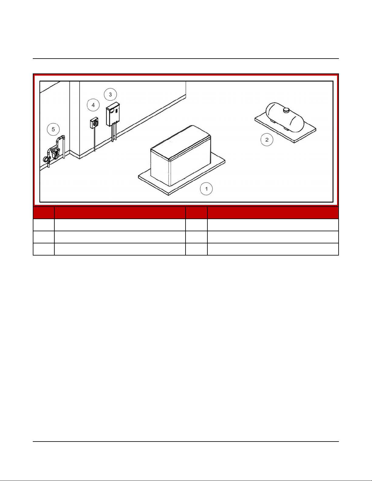
No. Description No. Description
1 Generator Set 4 Electrical Meter
2 Propane Tank 5 Natural Gas Meter
3 Transfer Switch
FIGURE 1. SITE PREPARATION EXAMPLE
Areas of consideration:
• Location of the generator set - this is one of the first decisions to be made, as it
affects all other aspects of the installation, such as:
◦ Length of electric wiring
◦ Length of gas lines (natural gas or propane - must be inspected by the gas
utility inspectors and building inspectors)
◦ Site preparation:
▪ Access to the site
▪ Trenches
▪ Site preparation materials needed
• Fuel supply pressure
• Automatic transfer switch location and connections
• Tools and materials required
21A045R241 (Issue 10) Copyright © 2017 Cummins Inc.
Page 26

3. Pre-Installation Considerations 8-2017
• Minimum distance from the propane tank fill (verify the legal minimum distance
with local code officials)
• Accessories required (if any) for the customer's application (utility power may
be required at the generator set; make plans accordingly)
NOTICE
Depending on the locality and use of the generator set, it may be necessary
to obtain an air quality emissions permit before installation begins. Check
with local pollution control or air quality authority to determine permit
requirements.
3.2 Installation Codes and Standards for Safety
NOTICE
The generator set installer bears sole responsibility for following all
applicable local codes and regulations.
The following list of codes and standards may apply to the installation and operation
of the generator set. This list is for reference only and not intended to be inclusive of
all applicable codes and standards. The address of each agency is listed so that
copies of the codes may be obtained for reference. Installation codes and
recommendations are subject to change, and may vary by location or over time.
22 A045R241 (Issue 10)Copyright © 2017 Cummins Inc.
Page 27

3. Pre-Installation Considerations8-2017
TABLE 14. INSTALLATION CODES AND STANDARDS FOR SAFETY
RECOMMENDATIONS
Type
US
Code or
Standard
Code
NFPA 70 - National Electrical
Code
Title Organization
NFPA 37 - Installation and Use
Code
of Stationary Combustion
Engines and Gas Turbines
Code
NFPA 54 - National Fuel Gas
Code
NFPA 58 - Storage and
Code
Handling of Liquefied Petroleum
Gases
NFPA 110 - Standard for
Code
Emergency and Standby Power
Systems
Code CSA Electrical Bulletin
Code
CSA 22.1 Canadian Electrical
Code
National Fire Protection
Association
470 Atlantic Avenue
Boston, MA 02210
Code
Canada
Standard
Standard
Code
Code
California Code
CSA B149 Installation Code for
Gas Burning Appliances and
Equipment
CSA C22.2 No. 100 Motors and
Generators
CSA C22.2 No. 14 Industrial
Control Equipment
CSA C282 Emergency Electrical
Power Supply for Buildings
CSA Z32 Electrical Safety in
Health Care Facilities
California Administrative Code Title 25 Chapter 3
Canadian Standards
Association
Housing and Construction
Materials Section
178 Rexdale Blvd.
Rexdale, Ontario, Canada M9Q
1R3
State of California
Documents Section
P.O. Box 1015
North Highlands, CA 95660
23A045R241 (Issue 10) Copyright © 2017 Cummins Inc.
Page 28

3. Pre-Installation Considerations 8-2017
3.3 Required Items for Installation
Tools and materials are used for the installation of this generator set. These items
are identified in the following sections. Please refer to local codes and standards,
because they may affect the materials required.
Materials Required
NOTICE
Refer to local codes and standards, which may affect material requirements.
NOTICE
If a 100% rated breaker is used, 90 °C wire must be used for L1, L2, and L3
with the wire size determined by the 75 °C ampacity tables.
NOTICE
A UL-listed grounding electrode terminal within its ratings and suitable for
the application must be installed and labeled “Grounding Electrode
Terminal”.
Electrical Materials:
NOTICE
Class 1 wiring methods must be used for connecting the generator set.
• Four code compliant AC power wires will be needed: L1, L2, N and Gnd (add
another wire for 3-phase for a total of 5 AC wires)
• For RA switches, 4 DC control wires will be needed from the generator to the
transfer switch.
• Wire sizes (DC control and power and AC sense only):
◦ DC control or AC sense wires under 1000 feet circuit length => 18-14
AWG of the insulation type below
◦ DC control or AC sense wires 1000-2000 feet circuit length => 16-14 AWG
of the insulation type below
• All AC and DC wires and cables shall be rated 75 °C minimum, stranded
copper, and rated for wet locations.
◦ For wire sizes 14 AWG and larger, use insulation types including but not
limited to: RHW, RHW-2, THHW, THW, THW-2, THWN, THWN-2, XHHW,
XHHW-2, USE-2, ZW-2
24 A045R241 (Issue 10)Copyright © 2017 Cummins Inc.
Page 29

3. Pre-Installation Considerations8-2017
◦ For wire sizes 16 and 18 AWG, use insulation types including but not
limited to: FFH-2, KFF-2, PAFF, PFF, PGFF, PTFF, RFH-2, RFHH-2,
RFHH-3, SFF-2, TFF, TFFN, ZFF
• Code compliant 20 A, 120 VAC, GFCI protected circuit for alternator heaters,
battery charger, coolant heater, oil heater, and/or battery heater (if equipped)
• Code compliant conduit for all wires
Mounting Materials:
• Four base tie-down bolts
NOTICE
Seismic zone installations require compliance to specific mounting
configurations.
Fuel Materials:
• Flexible fuel line (provided with the generator set, attached to the radiator
guard)
• UL listed pipe thread sealant
• Fuel line (natural gas and propane: 6-13 inches of water column [1.5 - 3.2 kPa]
fuel pressure) at generator set
• Fuel pressure regulator (as required)
• Manual fuel shut-off at generator set ahead of automatic valves on generator
set fuel system
Tools Required
Use appropriate lifting techniques to position the generator set in place.
Transfer Switch Requirements
A transfer switch must be a part of every generator set installation. Transfer
switches transfer loads to the generator set during power outages.
NOTICE
Cummins offers a variety of transfer switches, including residential and light
commercial options.
25A045R241 (Issue 10) Copyright © 2017 Cummins Inc.
Page 30
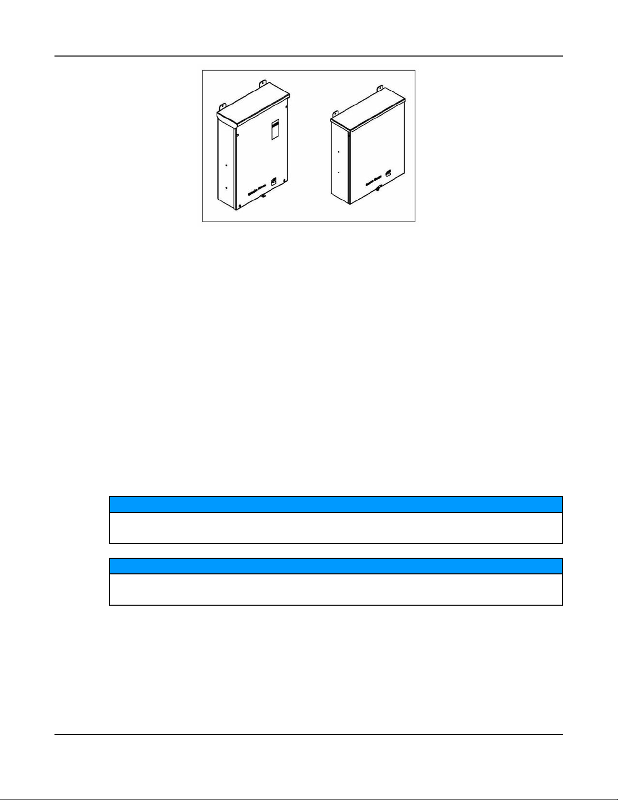
3. Pre-Installation Considerations 8-2017
FIGURE 2. CUMMINS TRANSFER SWITCH (RA SERIES)
Before beginning the installation of the transfer switch, verify that the unit was
correctly selected. Check the following features:
• Specifications (voltage, amperage, frequency, poles, and phases)
• Enclosure (indoor vs. outdoor)
• Model
Refer to the RA Series Transfer Switch Owner Manual (A046S594) for more
detailed information. The RA Series transfer switch is the recommended ATS for
use with these generators.
Choosing a Transfer Switch
This section includes block diagrams showing partial or full load coverage for the
Cummins RA Series transfer switches. For more information, see the RA Series
RA112L1 Automatic Transfer Switch Owner Manual (A052S254) or the RA Series
Automatic Transfer Switch Owner Manual (A046S594) (models RA112N3,
RA212N3, RA112S3, RA212S3, RA412N3, and RA412S3).
NOTICE
These generator sets can be used with either service entrance transfer
switches or non-service entrance transfer switches.
NOTICE
If the load exceeds the generator set rating, it may be necessary to use
Cummins’ load management kit (A051C329).
26 A045R241 (Issue 10)Copyright © 2017 Cummins Inc.
Page 31

3. Pre-Installation Considerations8-2017
FIGURE 3. TRANSFER SWITCH CONNECTIONS FOR PARTIAL COVERAGE LOAD
FIGURE 4. TRANSFER SWITCH CONNECTIONS FOR FULL COVERAGE LOAD
Loose Parts Shipped with the Generator Set
The following loose parts are shipped with the generator set:
• Flexible fuel hose assembly (attached to the radiator guard)
27A045R241 (Issue 10) Copyright © 2017 Cummins Inc.
Page 32

3. Pre-Installation Considerations 8-2017
• One enclosure key (where applicable)
• Battery tie-down
• Sound level 2 baffle (where applicable)
• Weather enclosure exhaust elbow (where applicable)
• Literature (operator manual, installation manual, health and safety manual, and
warranty statements)
28 A045R241 (Issue 10)Copyright © 2017 Cummins Inc.
Page 33

4 Installation
4.1 Site Assessment and Preparation
Proper component location and site preparation have a very important impact on
completing a successful installation. The major components and sources of power
needed for installation include the following items:
• Generator set
• Transfer switch
• Electrical utility
• Fuel source
• Accessories (may be required under certain conditions)
Generator Set Installation Suggestions and Guidelines
• Locate the generator set on stable ground, not subject to flooding. Generator
set should not be installed where significant water runoff from a roof or
downspouts is present. Sump pump discharge should be routed away from the
generator set.
• Locate and orient the generator set such that prevailing winds will carry exhaust
gases and fuel leaks away from the house or occupied areas.
• This unit is to be installed so that the risk of contact by people is minimized.
Picking a Location
WARNING
Exhaust gas is deadly. Locate the generator set away from doors, windows,
and other openings to the house and where exhaust gases will disperse
away from the house.
29A045R241 (Issue 10) Copyright © 2017 Cummins Inc.
Page 34

4. Installation 8-2017
No. Description No. Description
1 Cool Air In 3 Hot Air Out (Weather Enclosure)
2 Hot Air Out
FIGURE 5. EXAMPLE OF GENERATOR SET LOCATION
The generator set location is critical for safety and performance. Follow the
guidelines below:
• Must comply with applicable codes (NFPA, NEC, IBC, etc.).
• Use this manual for outdoor installations only. For other applications, contact
your local Cummins dealer or refer to the application manual at the following
link: http://www.cumminspower.com/www/literature/applicationmanuals/t030.pdf
• Consider access to utilities, such as electric/gas meters, transfer switch, remote
fuel tank location (for liquid propane if applicable), etc.
• Call the local utilities to mark the locations of buried utility services (gas,
electric, or telephone) before digging.
• Verify the locations of any other buried components (gas, electric or telephone)
with the homeowner before digging.
Follow the clearance guidelines below:
• The generator set must be located 5 feet from combustible materials (NFPA 37)
and any opening in a wall (window, door, vent, etc.).
• The generator set must be located such that the exhaust is not able to
accumulate in an occupied area.
• The generator set must have enough room for installation, service, and
maintenance.
• The generator set must be located to ensure ventilation openings are not
blocked.
30 A045R241 (Issue 10)Copyright © 2017 Cummins Inc.
Page 35

4. Installation8-2017
• Position the generator set so that cooling air is free to enter and leave the area.
• Locate and position the generator set so that prevailing winds carry exhaust
gases and potential fuel leaks away from the house or occupied area.
NOTICE
For all clearance requirements, refer to the Outline and System Drawings
section.
Laying the Foundation
When laying the foundation:
1. Clear obstructions, and make sure that there is adequate clearance for access.
2. Level the ground, and make sure that the ground is compact and settled.
Ensure that it is stable ground, not subject to flooding.
3. Prepare the concrete pad.
• The pad should be constructed of reinforced concrete with a 28-day
compressive strength of at least 2500 psi (17,237 kPa).
• The pad dimensions should be the same as those indicated in the Outline
and System Drawings appendix.
NOTICE
Seismic installations may require a different pad and securing
devices.
NOTICE
Local codes and standards may have different requirements.
4. Lift the generator set onto the pad, and secure it.
Lifting and Moving the Generator Set
WARNING
Heavy Load
The generator set is heavy. Handle with care.
Dropping the generator set can cause severe personal injury or death. Use
appropriate lifting techniques to move the generator set. Keep feet and
hands clear when lifting the generator set.
CAUTION
The generator set is shipped with oil in the engine crankcase. Keep the
generator set upright.
31A045R241 (Issue 10) Copyright © 2017 Cummins Inc.
Page 36

4. Installation 8-2017
Mounting the Generator Set
Mount the generator set on a substantial and level base such as a concrete pad. A
non-combustible material must be used for the pad. Verify that the mounting pad is
level by length, by width, and diagonally.
NOTICE
Seismic installation may require specific anchorage.
4.2 Fuel Selection and Fuel System Connection
This generator set has a convertible fuel system. The generator may run on natural
gas or propane, depending on the preferences of the owner. All generator sets
come preconfigured from the factory for natural gas fuel. For more information on
converting the fuel system type, see the Service Manual.
NOTICE
Fuel systems must be installed by qualified service technicians. Improper
installation presents hazards of fire and improper operation, resulting in
severe personal injury or property damage.
NOTICE
In some jurisdictions fuel system installations to the generator set must be
performed by licensed or registered personnel. Check with the authority
having jurisdiction for requirements.
WARNING
Gaseous fuels are flammable, explosive, and can cause severe personal
injury or death. Do not smoke if you smell gas, are near fuel tanks for fuelburning equipment, or are in an area sharing ventilation with such
equipment. Keep flames, sparks, pilot lights, electrical arcs, arc-producing
equipment and all other sources of ignition well away. Keep a type ABC fire
extinguisher handy.
In all fuel system installations, cleanliness is extremely important.
• Make every effort to prevent fuel contamination from:
◦ Moisture
◦ Dirt
◦ Excess thread sealant
◦ Contaminants of any kind
• Clean all fuel system components before installing.
32 A045R241 (Issue 10)Copyright © 2017 Cummins Inc.
Page 37

4. Installation8-2017
Gaseous-fuel supply system design, materials, components, fabrication, assembly,
installation, testing, inspection, operation, and maintenance must comply with the
applicable codes. See NFPA Standards No. 37, 54, and 58. If this is a seismic
installation, refer to IBC codes and standards. Where seismic installation is
required, there may be specific anchorage requirements for the generator set and
other installed components.
Most codes require a manual shutoff valve ahead of a flexible fuel hose. The
generator set includes electric (battery-powered) shutoff valves.
NOTICE
It is recommended that a shutoff valve be located near the generator set for
emergency shut off or servicing the generator set. Follow applicable codes.
Until the generator set is connected, cap the fuel line stub-up at the generator set to
prevent dirt from entering and gas from discharging if the gas supply shutoff valve is
opened accidentally.
To determine the required capacity, refer to the Fuel Line Selection section.
Fuel Line Connections
WARNING
Fuel presents the hazard of fire or explosion that can result in severe
personal injury or death. Do not smoke or allow any flame, spark, pilot light
or other ignition sources near fuel or in the installation area. Read the
important safety precautions in this manual.
1. Refer to the Outline and System Drawings appendix for the location of the fuel
supply connection through the side of the generator set.
2. Install a flexible fuel hose, which must be used between the engine's fuel
system and fuel supply line to protect the fuel system from damage caused by
vibration, expansion and contraction. The fuel hose must be installed according
to all applicable codes and standards.
Installing Fuel Lines
The basic components required for fuel line installation are as follows:
• Flexible fuel line (attached to the radiator guard)
• Fuel line
• Shutoff valve
• Fuel supply
To install the fuel lines:
1. Connect a flexible fuel line to the fuel connection ports on the generator set.
2. Connect the opposite end of the flexible fuel line to the fuel source line near the
shutoff valve.
33A045R241 (Issue 10) Copyright © 2017 Cummins Inc.
Page 38

4. Installation 8-2017
NOTICE
A shutoff valve is recommended and often required by local and state codes.
Natural Gas Fuel System
Requirements for a natural gas generator set are as follows:
TABLE 15. NATURAL GAS GENERATOR SET REQUIREMENTS
Component Description
Gas Pipeline quality
Fuel Supply Adequate fuel supply to operate correctly and run at full load
Shutoff Valve Manual
Fuel Pipe Size The length of the fuel supply pipe from the gas service entrance to the
generator set must be known to determine the correct fuel pipe size.
Refer to the charts in the Fuel Line Selection appendix.
Iron pipe must be a minimum of Schedule 40 subject to the authority
having jurisdiction.
Flexible Fuel Line Attached to the radiator guard. Protects the fuel system from vibration,
expansion, and contraction.
WARNING
Fuel leaks can lead to explosive accumulations of gas. Prevent gas leaks
and the accumulation of gaseous fuel in the event of a leak.
34 A045R241 (Issue 10)Copyright © 2017 Cummins Inc.
Page 39

No. Description No. Description
1 Shutoff Valve 3 Meter
4. Installation8-2017
2 Flexible Fuel Line (Attached to
Radiator Guard)
FIGURE 6. TYPICAL NATURAL GAS INSTALLATION
Natural Gas Supply Line Size
The natural gas supply meter may need to be exchanged for a higher capacity
meter to supply the additional gas consumed by the generator set.
Use the total load requirement of the generator set to determine the size of
the fuel supply pipe. Use the tables and charts in the Fuel Line Selection
appendix to determine the correct pipe size.
An older site might require upgrading and repair of the gas supply system.
Schedule an upgrade or repair to minimize power and gas supply
interruptions.
Make sure the full load fuel supply pressure at the inlet to the generator fuel
shutoff valves matches the requirements in the Model Specifications section.
Propane Fuel System
Propane vapor can be used as a primary fuel source or as a backup fuel source for
the generator sets with two independent fuel sources connected to the generator
set.
4 Secondary Regulator
WARNING
Fuel leaks can lead to explosive accumulations of gas. Propane sinks in air
and can accumulate inside housings, basements, and other below-grade
spaces. Prevent gas leaks and the accumulation of gaseous fuel in the event
of a leak.
35A045R241 (Issue 10) Copyright © 2017 Cummins Inc.
Page 40

4. Installation 8-2017
NOTICE
NFPA Standard No. 58 requires all persons handling and operating propane
to be trained in proper handling and operating procedures.
The required components in a propane vapor fuel system are as follows:
Component Description
Propane Tank Make sure to identify and use the correct tank size based on fuel flow
requirements and the lowest average temperature for your region. If the
tank is sized incorrectly, the generator set could run out of fuel. Refer to
the Fuel Line Selection appendix.
Shutoff Valve Useful during installation or in the event of a leak (may be required to
meet local codes).
Primary Regulator Located at the tank outlet, the primary regulator reduces the tank
pressure to the working pressure in the fuel supply line. Primary and
secondary regulators must be properly matched for a safe and functional
system. Consult with your propane supplier to ensure that the regulators
are properly sized.
Secondary
Regulator
Located near the generator set, the secondary regulator reduces the
higher line pressure to a working pressure that matches the
requirements in the Model Specifications section. Higher pressure before
the secondary regulator is necessary to ensure that there is enough fuel
available at the secondary regulator for a fully loaded generator set.
Fuel Line Connects to the fuel supply. It must be sized properly using the propane
fuel line sizing charts (refer to the Fuel Line Selection appendix).
Installation must comply with all national, state, and local codes.
Cummins Flexible
Fuel Line
Attached to radiator guard. Protects the fuel system from vibration,
expansion, and contraction.
36 A045R241 (Issue 10)Copyright © 2017 Cummins Inc.
Page 41

No. Description No. Description
1 Generator Set 4 Secondary Regulator
4. Installation8-2017
2 Flexible Fuel Line (Attached to
Radiator Guard)
3 Shutoff Valve
FIGURE 7. TYPICAL PROPANE INSTALLATION
Propane Fuel Requirements
Propane presents the hazard of fire or explosion that can cause severe
personal injury or death. Do not permit any flame, spark, arc-producing
equipment, switch, pilot light, cigarette, or other ignition source near
the fuel system. Keep an ABC type fire extinguisher nearby.
Fuel leaks can lead to explosive accumulations of gas. Propane sinks
in air and can accumulate inside housings, basements and other
below-grade spaces. Prevent gas leaks and the accumulation of
gaseous fuel in the event of a leak.
Use clean, fresh HD-5 grade propane or equivalent product consisting of at
least 90% propane.
5 Propane Tank
WARNING
WARNING
NOTICE
NFPA Standard No. 58 requires all persons handling and operating
propane to be trained in proper handling and operating procedures.
37A045R241 (Issue 10) Copyright © 2017 Cummins Inc.
Page 42

4. Installation 8-2017
NOTICE
Commercial propane may contain more than 2.5% butane, which can
result in poor fuel vaporization and low tank pressure, resulting in poor
engine starting and operation in below 32 °F (O °C) temperatures.
Propane Tank Size
When propane is used, size the tank correctly to ensure successful generator
set operation.
Considerations when figuring the proper propane tank size:
• Temperature is a critical factor that affects the size of the tank.
◦ Ambient temperatures can affect how quickly liquid is converted to
gas.
◦ Generator set fuel consumption is the same regardless of the
surrounding temperatures.
◦ Colder weather climates require larger fuel tanks. Larger tanks have
greater surface area, allowing more liquid propane to vaporize and
maintain the required fuel rate.
◦ Propane is stored as liquid. Keep the fuel tank at least 50% full to
operate properly. Fuel tanks that are less than 50% full may not have
the capacity to vaporize enough propane to operate the generator set
and other LP appliances.
• Propane tanks are sized by their internal volume in gallons, not the
amount of fuel they can hold (which is less).
• Propane tanks are generally filled to only 80% of their capacity.
Therefore, a 500-gallon (1892 L) tank results in 400-gallon (1514 L) tank
capacity.
• Low ambient temperatures affect the amount of fuel available from the
propane tank.
• Approximately 60% of the fuel (in gallons) filled in the tank can be
effectively used. Therefore, a 500-gallon (1892 L) tank results in 240gallon (908 L) usable capacity.
To assist in the proper installation of the propane tank, follow the guidelines
below.
• Consult your tank and propane supplier for assistance in all aspects of
determining tank size, selection of components and installation
requirements.
• Fit the propane tanks with a pressure reducing regulator before
connection to the generator set to prevent fuel system damage.
• Locate the propane tanks and all other fuel system components at least
10 feet (3 meters) from any source of combustion (including the generator
set). The fuel supplier or local code may require a larger distance
between the tank and source of combustion.
38 A045R241 (Issue 10)Copyright © 2017 Cummins Inc.
Page 43

4. Installation8-2017
• Install the propane tanks according to all national and local codes and
standards, and as required by the fuel tank and fuel supplier.
Refer to the Fuel Line Selection appendix for propane figures and tables.
Propane Vapor Fuel Supply Line Size and Pressure
Fuel line size depends on the amount of fuel needed to run the generator set
at full load at the distance the fuel must be moved.
To correctly size the fuel pipe, you must also take other loads operated from
the fuel supply line into consideration, such as space heating and water
heating equipment.
Use the total fuel requirement of the generator set and other connected
appliances to determine the size of the fuel supply pipe. Use the tables and
charts in the Fuel Line Selection appendix to determine the correct pipe size.
See the Model Specifications section for fuel system specifications, including
fuel consumption and required fuel system pressure at the generator set.
See the Propane Fuel System section for a typical propane vapor installation.
See the Fuel Line Selection appendix for fuel capacity at given distances and
pipe size.
NOTICE
Make sure the fuel supply pressure at the inlet of the generator set fuel
regulator (at service port) matches the requirements in the Model
Specifications section.
Converting the Fuel System Type
For single-fuel systems, the generator set leaves the factory configured for
natural gas. No mechanical parts are required for fuel conversion. To convert
the fuel system type, configure the control.
1. Enter the Fuel System Menu.
a. From any Info Menu, hold down the up and down arrows
simultaneously for two seconds. The Service Menu appears.
b. Select Setup Menus.
c. Enter the password 574 on the Password screen. The Setup Menu
appears.
d. Select Genset Service.
e. Select Genset.
f. Advance through the screens until the Fuel System Setup Menu
appears.
2. Update the Fuel System Type on the Fuel System Setup Menu. See the
figure below.
a. Press Adjust on the Fuel System Menu.
39A045R241 (Issue 10) Copyright © 2017 Cummins Inc.
Page 44

4. Installation 8-2017
b. Edit the Fuel System using the horizontal arrow key. Change the field
value by using the +/- keys.
FIGURE 8. FUEL SYSTEM TYPE
40 A045R241 (Issue 10)Copyright © 2017 Cummins Inc.
Page 45

4. Installation8-2017
3. Update the Gas Fuel Type on the Fuel System Menu.
a. When changing the Fuel System, a second Fuel System Menu is
enabled. Advance to this menu by pressing the down arrow after
saving any changes.
b. Press Adjust on the Fuel System Menu.
c. Edit the Gas Fuel Type by using the horizontal arrow key. See the
figure below.
FIGURE 9. GAS FUEL TYPE
d. Change the field value to Natural Gas, Liquid Propane, or Dual by
using the +/- keys.
e. Select Save to save the changes.
41A045R241 (Issue 10) Copyright © 2017 Cummins Inc.
Page 46

4. Installation 8-2017
Testing the Fuel System for Leaks
After assembly and before initial operation, all of the fuel system components must
be tested and proven free of any leaks.
WARNING
Fuel presents the hazard of explosion or fire which can result in severe
personal injury or death. Do not use an open flame to check for leaks. Do not
smoke or allow any flame, spark, pilot light, arc-producing equipment, switch
or other ignition sources around fuel or fuel components. Keep multi-type
ABC fire extinguishers close by.
NOTICE
Follow any local codes and standards, as they may require a different
method or documentation of a leak test.
Perform the following fuel piping system leak check:
1. After assembly and before initial operation of generator set, test all fuel system
components as required per the National Fuel Gas Code (NFPA 54).
2. The National Fuel Gas Code requires that the generator set be isolated from
the piping system by disconnecting it and capping the outlet prior to test. The
test pressure required is the greater of 1.5 times the supply pressure or 3 psi
(20.7 kPa) minimum.
3. After successfully completing the previous step, connect the generator set to
the fuel piping system.
4. To verify that all connections from the fuel piping system to the generator set
are free of leaks, conduct a bubble test using an approved leak detection
solution (or equivalent method) with the system pressure of 0.8 to 1.0 psi (5.5 to
7.0 kPa).
5. Spray the bubble solution on all of the joints.
6. Inspect all of the joints and monitor the line pressure. If bubbles appear, there is
a leak.
7. If any leaks are found, repair the joint or replace components as needed.
8. Verify the leak has been fixed.
NOTICE
The leak detection solution (that is, bubble solution) must be non-corrosive
and be free of ammonia and chlorine.
42 A045R241 (Issue 10)Copyright © 2017 Cummins Inc.
Page 47

4.3 Engine Exhaust
The exhaust system for this generator set is complete and was designed specifically
for this generator set. Do not modify or add to the exhaust system of this generator
set.
WARNING
Exhaust gas is deadly. Make sure that the exhaust system terminates away
from building vents, windows, doors, and sheltered spaces that may not
have ample fresh air ventilation.
WARNING
Engine discharge air and exhaust carry carbon monoxide gas (odorless and
invisible) which can cause asphyxiation and death. Never use engine
discharge air or exhaust for heating a room or enclosed space.
4.4 Electrical Connections
4. Installation8-2017
WARNING
Improper installation can lead to electrocution and damage to property.
Electrical connections must be made by a licensed electrician.
WARNING
Automatic startup of the generator set during installation can cause severe
personal injury or death. Make sure the generator set is shut down and
disabled:
1. Press the generator set's "O" (Off) button to stop the generator set.
Allow the generator set to thoroughly cool to the touch.
2. Turn off and disconnect the battery charger from the AC source before
disconnecting the battery cables.
3. Disconnect the negative (–) cable from the battery and secure it from
contacting the battery terminals to prevent accidental starting.
NOTICE
Refer to regional codes and the National Electrical Code (NFPA 70) for all
electrical installation requirements.
NOTICE
Class 1 wiring methods must be used for connecting the generator set.
43A045R241 (Issue 10) Copyright © 2017 Cummins Inc.
Page 48

4. Installation 8-2017
Electrical Preparations
1. Run all wires through a single conduit (unless prohibited by the authority having
jurisdiction).
NOTICE
Be sure to account for any needed accessories, such as a remote
display, etc.
2. Connect the conduit to the generator set. Refer to the specific outline drawing in
the Outline and System Drawings section for the size and location of the hole
provided for electrical conduit connection. The existing hole may be increased
in size to match conduit used.
AC Connections
WARNING
Automated Machinery
Accidental or remote starting of the generator set can cause severe personal
injury or death.
Isolate all auxiliary supplies and use an insulated wrench to disconnect the
starting battery cables, negative (–) cable first.
NOTICE
If a 100% rated breaker is used, 90 °C wire must be used for L1, L2, and L3
with the wire size determined by the 75 °C ampacity tables.
NOTICE
When using a circuit breaker with an adjustable, electronic trip unit, the
amperage and trip curve settings may need adjustment to match the
generator set load wiring, or downstream loads and circuit breakers. An
accessory seal kit (part number A026M166) is available to tamper-proof the
adjustable settings.
1. Make sure the generator set is shut down and disabled:
a. Press the Off switch from the display and then press the E-Stop button to
stop the generator set. Allow the generator set to thoroughly cool to the
touch.
b. Turn off and disconnect the battery charger from the AC source before
disconnecting the battery cables.
c. Disconnect the negative (–) cable from the battery and secure it from
contacting the battery terminals to prevent accidental starting.
2. Remove the enclosure side panel to access the main circuit breaker box.
3. Place the circuit breaker handle in the OFF position.
44 A045R241 (Issue 10)Copyright © 2017 Cummins Inc.
Page 49

4. Installation8-2017
4. Remove the four bolts holding the circuit breaker cover.
5. Connect the conductors to the circuit breaker load-side terminals, neutral lug,
and equipment grounding lug. For grounding and neutral connections, look for
the symbols on the generator set circuit breaker box (shown below, and in the
next image at the bottom).
Equipment Grounding Conductor Symbol Equipment Neutral Connection Symbol
FIGURE 10. SYMBOLS ON CIRCUIT BREAKER BOX
45A045R241 (Issue 10) Copyright © 2017 Cummins Inc.
Page 50

4. Installation 8-2017
FIGURE 11. CIRCUIT BREAKER AC LOAD CONNECTIONS LOCATION (SYMBOLS
SHOWN AT BOTTOM)
6. Torque the circuit breaker terminals per specifications on the circuit breaker
label.
7. Torque the neutral lug to 31.1 Nm (275 in-lb).
8. Torque the equipment grounding lug to 13.8 Nm (120 in-lb).
9. Fill in the stub-up openings with an approved duct seal or mastic tape to keep
out insects and rodents.
10. Install the circuit breaker cover.
46 A045R241 (Issue 10)Copyright © 2017 Cummins Inc.
Page 51

4. Installation8-2017
Automatic Transfer Switch AC Connections
WARNING
Failure to use an approved transfer switch can lead to the electrocution
of personnel working on the utility lines, damage to equipment, fire, or
personal injury. An approved switching device must be used to prevent
interconnection to the public utility.
Install the transfer switch in accordance with the appropriate RA Series
Transfer Switch Owner Manual.
Factory Option and Accessory Connections
NOTICE
Use copper conductors only.
AC powered options or accessories available:
• Battery charger
• Engine coolant heater
• Alternator heater
• Battery warmer
• CCV heater
47A045R241 (Issue 10) Copyright © 2017 Cummins Inc.
Page 52

4. Installation 8-2017
No. Description No. Description
1 AC Distribution Connector(s)
FIGURE 12. AC ACCESSORY CONNECTIONS
The battery charger, engine coolant heater, alternator heater, CCV heater,
and battery warmer require power from a 120 VAC, 20 Amp protected circuit
from the Main Distribution Panel. Use 12 AWG 75 °C (167 °F) conductors to
make connection to the generator set AC distribution connector.
DC Connections
NOTICE
When selecting and installing conduit to the generator set, account for any
needed accessories, such as a remote display, etc.
48 A045R241 (Issue 10)Copyright © 2017 Cummins Inc.
Page 53

4. Installation8-2017
FIGURE 13. DC CUSTOMER CONNECTIONS
Automatic Transfer Switch DC Connections
WARNING
Failure to use an approved transfer switch can lead to the electrocution
of personnel working on the utility lines, damage to equipment, fire, or
personal injury. An approved switching device must be used to prevent
interconnection to the public utility.
49A045R241 (Issue 10) Copyright © 2017 Cummins Inc.
Page 54

4. Installation 8-2017
Install the transfer switch in accordance with the appropriate RA Series
Transfer Switch Owner Manual.
The following image is an example that shows the location of the connectors
in the generator set where the ATS DC control wires terminate. This is also
the location of the connectors where load management control wires (if
applicable) terminate.
Refer to the Wiring Diagrams appendix for generator set to RA transfer switch
DC customer connections.
NOTICE
Class 1 wiring methods should be used for connecting the generator
set and transfer switch signal wiring.
FIGURE 14. EXAMPLE OF RA SERIES TRANSFER SWITCH DC CONNECTIONS
LOCATION
50 A045R241 (Issue 10)Copyright © 2017 Cummins Inc.
Page 55

4. Installation8-2017
Drilling Locations for Electrical Connections
Preferred routing of electrical leads is vertically through conduit that is installed in
the mounting pad that terminates in the electrical connection areas.
• Refer to the generator set foundation outline drawing in the Outline and System
Drawings appendix for location of electrical connection areas.
• In some cases, it may be necessary to route electrical leads horizontally in
conduits that pass through the generator set chassis.
• Refer to the figure below for available drilling space for conduit holes in the side
of the chassis. Holes up to 7.6 cm (3 in) in diameter can be made in the
chassis in the areas shown. Exceeding 7.6 cm (3 in) in diameter may cause
failure of the chassis.
• Comply with NEC and local codes and standards for installation of wires for
electrical circuits. Refer to NEC standards for required wire bend radius and
ampacity of load leads.
No. Description No. Description
1 Circuit Breaker Side 3 Drilling Allowed (Shaded Areas)
2 DC (Left) and AC (Right) Connection
Area
FIGURE 15. DRILLING LOCATIONS FOR SIDE ELECTRICAL CONNECTIONS
51A045R241 (Issue 10) Copyright © 2017 Cummins Inc.
Page 56

4. Installation 8-2017
No. Description No. Description
1 Circuit Breaker 2 Maximum 7.6 cm (3 in) Bend Radius
Gap
FIGURE 16. CABLING ROOM FOR CIRCUIT BREAKER
Grounding
NOTICE
The generator set is shipped from the factory with the neutral and equipment
ground not bonded together.
Refer to local codes and standards for grounding procedures.
Battery
The generator set requires a 12V battery (negatively grounded) for engine cranking
and powering the electronic control system. When the generator set is running, the
battery is charged from the engine-driven battery alternator. When the set is not
running, an AC powered battery charger is needed to keep the battery charged.
As part of the installation, make sure that the battery is secured to the battery tray
with the strap provided.
To connect the battery:
1. Connect the positive battery terminal.
2. Connect the negative battery terminal.
3. Make sure that the black and red battery cable boots are in place.
Refer to the Model Specifications section for battery specifications.
An optional thermostatically controlled battery heater is available for more reliable
starting in ambient temperatures down to -40 °F (-40 °C).
52 A045R241 (Issue 10)Copyright © 2017 Cummins Inc.
Page 57

4. Installation8-2017
To prevent injury due to accidental startup:
• Do not connect the battery cables to the battery until the installation has been
completed;
• Make sure tools, rags, and body parts are kept away from any rotating parts or
electrically live parts; and
• Make sure it is time to start the generator set.
NOTICE
Ensure that the AC power to the battery charger is disconnected when
installing the battery.
NOTICE
Wear proper safety protection when working around batteries. Keep open
flames and sparks away from the equipment.
NOTICE
Only personnel knowledgeable of batteries and required precautions should
perform or supervise battery servicing.
53A045R241 (Issue 10) Copyright © 2017 Cummins Inc.
Page 58

4. Installation 8-2017
FIGURE 17. BATTERY LOCATION
54 A045R241 (Issue 10)Copyright © 2017 Cummins Inc.
Page 59

5 Startup and Configuration
5.1 Time Setup (1-Phase ATS)
NOTICE
When battery power is lost, these settings must be reset.
NOTICE
Not applicable without a single phase RA series transfer switch.
To set up the generator set clock for the current date and time:
1. From any Information Menu, hold down the up and down arrows simultaneously
for two seconds. The Service Menu appears.
2. Access the Time Setup screen by selecting Clock Exerciser on the Genset
Service Menu.
3. Select Adjust.
When updating these settings, the functions of the keys are as follows:
• The horizontal right arrow key is used to select successive blocks for editing
settings on the screen.
• Select the left arrow to return to the previous screen.
• Adjust values by using the + or - keys on the Adjust Menu of the Time Setup
screen.
• Press Save to save any changes. After saving, the Save button changes to the
Adjust button.
FIGURE 18. TIME SETUP SCREEN
55A045R241 (Issue 10) Copyright © 2017 Cummins Inc.
Page 60

5. Startup and Configuration 8-2017
Updating Daylight Saving Adjust Screens
Update Values on the Daylight Saving Adjust Screen
1. From any Information Menu, hold down the up and down arrows simultaneously
for two seconds. The Service Menu appears.
2. Navigate to the Genset Service Menu.
3. Select Clock Exerciser to access the Time Setup screen.
4. Press the down key on the Time Setup screen to access the Daylight Saving
Adjust screen.
5. Select Adjust. When updating these settings, the functions of the keys are as
follows:
TABLE 16. KEY FUNCTIONS ON THE DAYLIGHT SAVING ADJUST SCREEN
Key/Button Function
Horizontal right arrow key Select successive blocks for editing settings on the screen
Left arrow key Return to the previous screen
+ or - keys Adjust values on the Adjust screen of the Daylight Saving Adjust
screen
Save button Save any changes; after saving, the Save button changes to the
Adjust button
FIGURE 19. "DAYLIGHT SAVING ADJUST SAVING TIME" SCREEN NAVIGATION
Access and Update the Daylight Saving Adjust Start Screen
1. Press the down arrow key on the Daylight Saving Adjust screen.
2. Press Adjust. When updating these settings, the functions of the keys are as
follows:
56 A045R241 (Issue 10)Copyright © 2017 Cummins Inc.
Page 61

5. Startup and Configuration8-2017
TABLE 17. KEY FUNCTIONS ON THE DAYLIGHT SAVING ADJUST START SCREEN
Key/Button Function
Horizontal right arrow key Select successive blocks for editing settings on the screen
+ or - keys Adjust Month, Week, Day or Hour
Save button Save any changes; after saving, the Save button changes to the
Adjust button
FIGURE 20. DAYLIGHT SAVING ADJUST START SCREEN
Update the Daylight Saving Adjust End Screen
1. Press the down key on the Daylight Saving Adjust Start screen.
2. Press Adjust. When updating these settings, the functions of the keys are as
follows:
TABLE 18. KEY FUNCTIONS ON THE DAYLIGHT SAVING ADJUST END SCREEN
Key/Button Function
Horizontal right arrow key Select successive blocks for editing settings on the screen
+ or - keys Adjust Month, Week, Day or Hour
Save button Save any changes; after saving, the Save button changes to the
Adjust button
57A045R241 (Issue 10) Copyright © 2017 Cummins Inc.
Page 62

5. Startup and Configuration 8-2017
FIGURE 21. DAYLIGHT SAVING ADJUST END SCREEN
5.2 Exercise Settings
When battery power is lost, these settings must be reset.
Not applicable without a single phase RA series transfer switch.
To access the Clock/Exerciser Menu:
1. From any Information Menu, hold down the up and down arrows simultaneously
for two seconds. The Service Menu appears.
2. Navigate through the screens to find and select Clock/Excr in the Service
Menu.
The following screens represent the standard operator panel (that is,
HMI211). If using an in-home operator panel, which may be additionally
purchased as an option, the screens may look slightly different. This
procedure applies to both operator panels.
NOTICE
NOTICE
NOTICE
58 A045R241 (Issue 10)Copyright © 2017 Cummins Inc.
Page 63

5. Startup and Configuration8-2017
FIGURE 22. CLOCK/EXERCISER MENU NAVIGATION
59A045R241 (Issue 10) Copyright © 2017 Cummins Inc.
Page 64

5. Startup and Configuration 8-2017
Updating Exercise Frequency (1-Phase ATS)
NOTICE
Not applicable without a single phase RA series transfer switch.
To update the exercise frequency and dates on the Clock/Exerciser Menu:
1. From any Information Menu, hold down the up and down arrows simultaneously
for two seconds. The Service Menu appears.
2. Access the Time Setup screen by selecting Clock Exerciser on the Genset
Service Menu.
3. Press the down key on the Time Setup screen to access the Daylight Saving
Adjust screen.
4. Select Adjust.
5. Press the down key on the Daylight Saving Adjust Start screen.
6. Select Adjust.
7. Press Exercise Schdr on the Daylight Saving Adjust End screen.
8. Press Adjust.
When updating these settings, the functions of the keys are as follows:
• The horizontal right arrow key is used to select successive blocks for editing
settings on the screen.
• Use the + or - keys to edit the following settings:
◦ Schdr Enable: Enable or Disable
◦ Exercise Schedule: Semi-Annual (every six months), Quarterly, Monthly,
Bi-Monthly (the first and third week of every month based on the time set
when the Bi-Monthly option is selected), or Weekly
◦ Exercise Schedule: Day, Hours, Minutes, AM/PM
• Press Save to save any changes. After saving, the Save button changes to the
Adjust button.
60 A045R241 (Issue 10)Copyright © 2017 Cummins Inc.
Page 65

5. Startup and Configuration8-2017
FIGURE 23. EXERCISE FREQUENCY NAVIGATION
Updating Exercise Duration (1-Phase ATS)
NOTICE
Not applicable without a single phase RA series transfer switch.
To update the exercise duration on the Clock/Exerciser Menu:
1. From any Information Menu, hold down the up and down arrows simultaneously
for two seconds. The Service Menu appears.
2. Access the Time Setup screen by selecting Clock Exerciser on the Genset
Service Menu.
3. Press the down key on the Time Setup screen to access the Daylight Saving
Adjust screen.
4. Select Adjust.
5. Press the down key on the Daylight Saving Adjust Start screen.
6. Select Adjust.
7. Press Exercise Schdr on the Daylight Saving Adjust End screen.
8. Press the down key on the Exercise Schdr Menu.
9. Press Adjust.
When updating these settings, the functions of the keys are as follows:
• The horizontal right arrow key is used to select the duration block for editing
exercise duration.
• Use the + or - keys to edit the exercise duration minutes.
61A045R241 (Issue 10) Copyright © 2017 Cummins Inc.
Page 66

5. Startup and Configuration 8-2017
• Press Save to save any changes. After saving, the Save button changes to the
Adjust button.
FIGURE 24. EXERCISE DURATION NAVIGATION
5.3 Brightness and Contrast
The Screen Adjust screen allows the contrast, brightness, and units to be set. To
access the Screen Adjust screen:
1. From any Information screen, hold down the up and down arrows
simultaneously for two seconds to gain access to the Service Menu screen.
2. Select Screen Adjust.
To adjust the contrast, brightness, or units from the Screen Adjust screen:
1. From the Screen Adjust screen, select Adjust to access the screen variables.
2. Press the right arrow to move between the variables.
3. Adjust settings, and press Save to save any changes.
When updating these settings, the functions of the keys are as follows:
• The horizontal right arrow key is used to select successive blocks for editing
settings on the screen.
• Select the left arrow to return to the previous screen.
• Adjust values by using the + or - keys on the Adjust screen of the Display
Setup screen.
• Press Save to save any changes. After saving, the Save button changes to the
Adjust button.
62 A045R241 (Issue 10)Copyright © 2017 Cummins Inc.
Page 67

5. Startup and Configuration8-2017
NOTICE
The following screens represent the standard operator panel (HMI211). If
using an in-home operator panel, which may be additionally purchased as an
option, the screens may look slightly different. This procedure applies to
both operator panels.
FIGURE 25. BRIGHTNESS AND CONTRAST SCREEN NAVIGATION
63A045R241 (Issue 10) Copyright © 2017 Cummins Inc.
Page 68

5. Startup and Configuration 8-2017
NOTICE
Adjusting the brightness on the operator panel adjusts the brightness of
both the LCD backlight and the LEDs on the display. The contrast should
never be 0 or 100% on any of the screens. The default value for Brightness is
50%.
5.4 History and About Menu
To access the History/About screen:
1. From any Information Menu, hold down the up and down arrows simultaneously
for two seconds. The Service Menu appears.
2. Select History/About.
3. Advance through the screens to view information about the generator set,
control, and display.
NOTICE
The following screens represent the standard operator panel (HMI211). If
using an in-home operator panel, which may be additionally purchased as an
option, the screens may look slightly different. This procedure applies to
both operator panels.
64 A045R241 (Issue 10)Copyright © 2017 Cummins Inc.
Page 69

5. Startup and Configuration8-2017
FIGURE 26. HISTORY/ABOUT MENU
65A045R241 (Issue 10) Copyright © 2017 Cummins Inc.
Page 70

5. Startup and Configuration 8-2017
5.5 InPower Service Tool
The InPowerTMservice tool can be used in troubleshooting to perform tests, verify
control inputs and outputs, and test protective functions. Refer to the InPower
User's Guide, provided with the InPower software for test procedures.
Disabling the AMF Feature
NOTICE
This procedure must be performed by a qualified technician.
On single-phase units, the control is shipped with the Automatic Mains Failure
(AMF) feature enabled. This feature has logic to control the RA Automatic Transfer
Switch (ATS), including a 5-minute retransfer to utility delay. If you are not using an
RA ATS, you can eliminate the 5-minute retransfer to utility delay by disabling the
AMF feature using the instructions below.
NOTICE
This procedure is optional. If you do not disable the AMF feature, the
generator set will just run for an additional 5 minutes after the utility has
been restored.
NOTICE
These steps cannot be performed with the HMI211; they can only be
performed with the InPower service tool.
1. Connect to the PCC1302 via InPower.
2. Navigate to the Adjustments->Features->Automatic Transfer Switch folder.
3. Select the Auto Mains Failure Enable parameter.
4. Double-click on Enabled in the Value field.
5. A pop-up will appear with available choices. Select Disabled.
6. Select Device->Save Adjustments from the top menu bar.
7. A pop-up will appear asking if the change is to be saved. Click the Save
button.
8. After a pop-up appears confirming that the change has been saved, disconnect
InPower from the PCC1302.
66 A045R241 (Issue 10)Copyright © 2017 Cummins Inc.
Page 71

5.6 Installation Checklist
Tick Item
General
Generator set wattage capacity is sufficient to handle maximum anticipated load.
At least 5 feet of clearance to combustible materials is provided. At least 3 feet of
clearance is provided around the entire generator set for service and ventilation.
The generator set is located in an area not subject to flooding.
All installers have read and are familiar with the Generator Set Installation manual and
the Health and Safety manual.
All installers have been thoroughly briefed on preventive maintenance procedures.
All installers have read and understand all important safety instructions.
Generator Set Support
The floor, roof or earth on which the generator set rests is strong enough and will not
allow shifting or movement. Local codes for soil bearing capacity were followed.
5. Startup and Configuration8-2017
The generator set is properly supported and secured to an approved base.
The supporting base is of non-combustible material and extends 6 inches all around
the generator set.
Fuel System
Verify that the generator set is configured to the fuel being used. (See the Fuel
Selection and Fuel System Connection section.)
Fuel line size has been verified for generator set fuel consumption and pressure.
Approved flexible fuel line is installed between main fuel supply and the generator
set’s fuel system near the generator set
Fuel lines are properly installed, supported and protected against damage.
Fuel supply shutoff valves are installed to turn off fuel flow in case of leaks.
No leaks are found in fuel supply line as a result of leak testing fuel systems.
The inside of all fuel supply lines is free of contaminants.
Fuel pressure is at 6-13 inches of water column (1.5 - 3.2 kPa) under any condition.
Fuel pressure maintains at least 6 inches water column (1.5 kPa) when the generator
set is at rated load.
The installation is compliant with all state and local codes and regulations.
AC and DC Wiring
Wire sizes, wire types, insulation, conduits and connection methods all meet
applicable codes.
67A045R241 (Issue 10) Copyright © 2017 Cummins Inc.
Page 72

5. Startup and Configuration 8-2017
Tick Item
AC and DC wires are separated in their own conduit to prevent electrical induction.
All load, line and generator connections are well made and correct.
Generator Set Pre-Start
A safety check was performed just before starting.
The generator set engine is properly serviced with oil and coolant.
The battery is properly installed, serviced and charged.
The battery charger and engine coolant heater are connected and operational, if
applicable.
All generator set covers and safety shields are installed correctly.
The fuel supply is turned on.
All fuel shutoff valves are operational.
The date and time have been set in the generator set control.
The generator set operating mode has been selected.
5.7 Startup
Automated Machinery
Accidental or remote starting of the generator set can cause severe personal
injury or death.
Isolate all auxiliary supplies and use an insulated wrench to disconnect the
starting battery cables, negative (–) cable first.
After verifying that the installation was completed correctly, start and test the
system. Make sure to connect the battery cables to the battery with the positive (+)
cable first.
Read through the Operator Manual and perform the maintenance and pre-start
checks as instructed.
The following information applies to C70 N6, C80 N6, and C100 N6 generator set
models only: Adaptive learn is an engine ECM function that allows the generator set
to "learn" its environment. There are small differences in the performance of each
engine and fuel system component, so the ECM uses inputs from the engine
sensors to adjust running conditions to operate more consistently for each individual
generator set. After installation is complete and while testing the overall system
function, the generator set must be run with no active faults under load (that is,
transfer switch connected to maximum customer load available) until the engine
temperature reaches 80 °C (175 °F) to allow the adaptive learn function to initialize.
WARNING
68 A045R241 (Issue 10)Copyright © 2017 Cummins Inc.
Page 73

5. Startup and Configuration8-2017
The generator set is shipped from the factory with the proper level of engine oil and
coolant, but each should be checked before the generator set is started. Start and
operate the generator set following all the instructions and precautions in the
Operator Manual. Ensure that the bonding bolts are installed into the service panels
before leaving the site.
NOTICE
Before leaving the site, if the generator set is ready to be placed in service,
put the generator set in Auto mode to provide automatic standby power.
NOTICE
Contact your local Cummins service representative if you encounter a fault
code.
69A045R241 (Issue 10) Copyright © 2017 Cummins Inc.
Page 74

5. Startup and Configuration 8-2017
This page is intentionally blank.
70 A045R241 (Issue 10)Copyright © 2017 Cummins Inc.
Page 75

Appendix A. Fuel Line Selection
Table of Contents
Table 20. Required Information for Determining Fuel Line Size ............................................................. 72
Table 22. NFPA Equivalent Lengths of Pipe Fittings and Valves in Feet (Meters) ................................ 73
Table 24. Natural Gas Schedule 40 Metallic Pipe Sizing in Inches ......................................................... 74
Table 27. Natural Gas Semirigid Copper Tubing Sizing ........................................................................... 76
Table 30. Propane Vapor Schedule 40 Metallic Pipe Sizing .................................................................... 78
Table 33. Propane Vapor Semirigid Copper Tubing Sizing ..................................................................... 79
Table 36. Propane Schedule 40 Iron Pipe Sizing, Liquid Withdrawal (Maximum Capacity of Pipe in
Cubic Feet of Gas per Hour)* ...................................................................................................................... 81
Figure 27. Minimum LPG Tank Size (50% Full) Required to Maintain 5 PSIG at Specific Withdrawal
Rate and Minimum Expected Winter Temperature ................................................................................... 83
71A045R241 (Issue 10) Copyright © 2017 Cummins Inc.
Page 76

Appendix A. Fuel Line Selection 8-2017
A.0 Fuel System Pipe Sizing Introduction
Incorrect fuel line size may cause the generator set to not run or provide
full power output.
Tables are included in this section to help calculate pipe sizing for natural
gas and propane vapor withdrawal under specified conditions. Consult
NFPA 54 or other applicable codes for other operating conditions or other
fuel system installation requirements.
Refer to the Engineering Application Manual T-030: Liquid Cooled
Generator Sets manual (A040S369) for more information.
To determine the optimal fuel line size, the following information is
needed:
TABLE 20. REQUIRED INFORMATION FOR DETERMINING FUEL
LINE SIZE
Category Description
Fuel Flow
Requirements for
the Generator Set
Fuel Source
(Natural Gas or
Propane Vapor)
Fuel Line Length
(Including Fittings)
Fuel Line Type
(e.g., Copper
Tubing or Iron
Pipe)
NFPA 54 has selection tables for other approved fuel lines. Verify
with the authorities having jurisdiction the allowed fuel line type for
the generator set installation.
Fuel flow requirements have a large impact on fuel
line size.
Fuel sources can affect fuel line size. Natural gas
installations generally require a higher fuel flow rate
compared to propane vapor installations, since
propane has a higher energy content.
As fuel line lengths increase, they may require larger
diameter fuel lines. Be sure to consider the
equivalent length of all of the fittings (elbows, tees,
valves) in the installation in addition to the straight
pipe length.
Most fuel line types are iron pipe or copper tubing.
Be sure to use the sizing chart for the fuel line type
when sizing the fuel line.
NOTICE
72 A045R241 (Issue 10)Copyright © 2017 Cummins Inc.
Page 77

A.1 Gas Pipe Sizing
The following tables in this section are reprinted with permission
from NFPA 54-2015, National Fuel Gas Code, Copyright © 2014,
National Fire Protection Association.
• Natural Gas Schedule 40 Metallic Pipe Sizing
• Natural Gas Semirigid Copper Tubing Sizing
• Propane Vapor Schedule 40 Iron Pipe Sizing
• Propane Vapor Semirigid Copper Tubing Sizing
• Propane Schedule 40 Iron Pipe Sizing, Liquid Withdrawal
(Maximum Capacity of Pipe in Cubic Feet of Gas per Hour)
This reprinted material is not the complete and official position of
the NFPA on the referenced subject, which is represented only by
the standard in its entirety.
Appendix A. Fuel Line Selection8-2017
NOTICE
Sizing of gas piping for proper fuel delivery, both flow and pressure, can
become quite complex. A simplified method is to convert all fittings,
valves, etc. to equivalent lengths of pipe in the diameter(s) being
considered. The total equivalent length can then be related to flow
capacity. Equivalent lengths of pipe fittings and valves can be found in the
table below.
TABLE 22. NFPA EQUIVALENT LENGTHS OF PIPE FITTINGS AND VALVES IN FEET
(METERS)
Nominal Inch (Millimeters) Pipe Size
Type of Fitting
90° Std. Elbow or
Tee Reduced ½.
90° Long Radius
Elbow or Straight
Run Tee
45° Elbow 0.8
1/2
(15)
1.6
(0.5)
1.0
(0.3)
(0.2)
3/4
(20)1(25)
2.0
(0.6)
1.4
(0.4)
0.9
(0.3)
2.6
(0.8)
1.7
(0.5)
1.3
(0.4)
1-1/4
(32)
3.3
(1.0)
2.3
(0.7)
1.7
(0.5)
1-1/2
(40)
4.0
(1.2)
2.6
(0.8)
2.1
(0.6)
2
(50)
5.0
(1.5)
3.3
(1.0)
2.6
(0.8)
2-1/2
(65)
6.0
(1.8)
4.1
(1.3)
3.2
(1.0)
3
(80)
7.5
(2.3)
5.0
(1.5)
4.0
(1.2)
4
(100)
10.0
(3.1)
6.7
(2.0)
5.2
(1.6)
180° Std. Bend 2.5
(0.8)
TEE, Side Inlet or
Outlet
(0.9)
3.0
3.2
(1.0)
4.0
(1.2)
4.1
(1.2)
5.0
(1.5)
5.6
(1.7)
7.0
(2.1)
6.3
(1.9)
8.0
(2.4)
73A045R241 (Issue 10) Copyright © 2017 Cummins Inc.
8.2
(2.5)
10.0
(3.0)
10.0
(3.1)
12.0
(3.7)
12.0
(3.7)
15.0
(4.6)
17.0
(5.2)
21.0
(6.4)
Page 78

Appendix A. Fuel Line Selection 8-2017
Foot Valve and
Strainer
Swing Check
Valve,
Fully Open
Globe Valve,
Fully Open
Angle Valve, Fully
Open
Gate Valve, Fully
Open
3.7
(1.1)
6.0
(1.8)
18.0
(5.5)
7.0
(2.1)
0.7
(0.2)
4.9
(1.5)
8.0
(2.4)
22.0
(6.7)
9.0
(2.7)
0.9
(0.3)
7.5
(2.3)
10.0
(3.0)
29.0
(8.8)
12.0
(3.7)
1.0
(0.3)
8.9
(2.7)
14.0
(4.3)
38.0
(11.6)
15.0
(4.6)
1.5
(0.5)
11.0
(3.4)
16.0
(4.9)
43.0
(13.1)
18.0
(5.5)
1.8
(0.5)
15.0
(4.6)
20.0
(6.1)
55.0
(16.8)
24.0
(7.3)
2.3
(0.7)
18.0
(5.5)
25.0
(7.6)
69.0
(21.0)
29.0
(8.8)
2.8
(0.9)
22.0
(6.7)
30.0
(9.1)
84.0
(25.6)
35.0
(10.7)
3.2
(1.0)
29.0
(8.8)
40.0
(12.2)
120.0
(36.6)
47.0
(14.3)
4.5
(1.4)
The remaining tables in this section show maximum gas capacity for
equivalent lengths of various pipe sizes.
Here are some basic but very important steps that all installers must
follow to make sure that fuel lines are sized correctly:
1. Verify adequate fuel flow, quality, and pressure available from the
natural gas utility connection or the propane system.
2. Obtain the maximum fuel consumption requirements at full load for
the specific generator set from the Model Specifications section and
for all gas appliances attached to the pipe system.
3. Make a list of all the fittings and valves in the proposed system used
in this generator set installation.
4. Determine the equivalent length of all fuel line fittings (elbows, tees,
and valves). (See the NFPA Pipe Fittings table in this appendix to
determine the equivalent lengths for all fuel line fittings.)
5. Add the equivalent length of the fuel line fittings to the lengths of
straight pipe to determine the total equivalent length of the system.
6. Choose the applicable table in this appendix based on the fuel type
(natural gas, propane vapor or liquid propane) and fuel line material.
7. Determine the fuel line size at full load:
a. Locate the equivalent length of pipe (or next larger equivalent
length) in the left hand column.
b. Move across the row to where the maximum flow capacity
number is as large or larger than the maximum fuel consumption.
c. Move to the top of that column to where the minimum nominal
pipe size or tubing size required for the system as designed is
shown.
TABLE 24. NATURAL GAS SCHEDULE 40 METALLIC PIPE SIZING IN INCHES
Gas: Natural
74 A045R241 (Issue 10)Copyright © 2017 Cummins Inc.
Page 79

Appendix A. Fuel Line Selection8-2017
Inlet Pressure: Less than 2 psi
Pressure Drop: 0.5 in. water column
Specific Gravity: 0.6
Pipe Size
Nominal: 1⁄2 3⁄4 1 11⁄4 11⁄2 2 21⁄2 3 4 5 6 8 10 12
Actual ID: 0.622 0.824 1.049 1.38 1.61 2.067 2.469 3.068 4.026 5.047 6.065 7.981 10.02 11.938
Length (ft) Capacity in Cubic Feet of Gas per Hour
10 172 360 678 1390 2090 4020 6400 11300 23100 41800 67600 139000 252000 399000
20 118 247 466 957 1430 2760 4400 7780 15900 28700 46500 95500 173000 275000
30 95 199 374 768 1150 2220 3530 6250 12700 23000 37300 76700 139000 220000
40 81 170 320 657 985 1900 3020 5350 10900 19700 31900 65600 119000 189000
50 72 151 284 583 873 1680 2680 4740 9660 17500 28300 58200 106000 167000
60 65 137 257 528 791 1520 2430 4290 8760 15800 25600 52700 95700 152000
70 60 126 237 486 728 1400 2230 3950 8050 14600 23600 48500 88100 139000
80 56 117 220 452 677 1300 2080 3670 7490 13600 22000 45100 81900 130000
90 52 110 207 424 635 1220 1950 3450 7030 12700 20600 42300 76900 122000
100 50 104 195 400 600 1160 1840 3260 6640 12000 19500 40000 72600 115000
125 44 92 173 355 532 1020 1630 2890 5890 10600 17200 35400 64300 102000
150 40 83 157 322 482 928 1480 2610 5330 9650 15600 32100 58300 92300
175 37 77 144 296 443 854 1360 2410 4910 8880 14400 29500 53600 84900
200 34 71 134 275 412 794 1270 2240 4560 8260 13400 27500 49900 79000
250 30 63 119 244 366 704 1120 1980 4050 7320 11900 24300 44200 70000
300 27 57 108 221 331 638 1020 1800 3670 6630 10700 22100 40100 63400
350 25 53 99 203 305 587 935 1650 3370 6100 9880 20300 36900 58400
400 23 49 92 189 283 546 870 1540 3140 5680 9190 18900 34300 54300
450 22 46 86 177 266 512 816 1440 2940 5330 8620 17700 32200 50900
500 21 43 82 168 251 484 771 1360 2780 5030 8150 16700 30400 48100
550 20 41 78 159 239 459 732 1290 2640 4780 7740 15900 28900 45700
600 19 39 74 152 228 438 699 1240 2520 4560 7380 15200 27500 43600
650 18 38 71 145 218 420 669 1180 2410 4360 7070 14500 26400 41800
700 17 36 68 140 209 403 643 1140 2320 4190 6790 14000 25300 40100
75A045R241 (Issue 10) Copyright © 2017 Cummins Inc.
Page 80

Appendix A. Fuel Line Selection 8-2017
750 17 35 66 135 202 389 619 1090 2230 4040 6540 13400 24400 38600
800 16 34 63 130 195 375 598 1060 2160 3900 6320 13000 23600 37300
850 16 33 61 126 189 363 579 1020 2090 3780 6110 12600 22800 36100
900 15 32 59 122 183 352 561 992 2020 3660 5930 12200 22100 35000
950 15 31 58 118 178 342 545 963 1960 3550 5760 11800 21500 34000
1000 14 30 56 115 173 333 530 937 1910 3460 5600 11500 20900 33100
1100 14 28 53 109 164 316 503 890 1810 3280 5320 10900 19800 31400
1200 13 27 51 104 156 301 480 849 1730 3130 5070 10400 18900 30000
1300 12 26 49 100 150 289 460 813 1660 3000 4860 9980 18100 28700
1400 12 25 47 96 144 277 442 781 1590 2880 4670 9590 17400 27600
1500 11 24 45 93 139 267 426 752 1530 2780 4500 9240 16800 26600
1600 11 23 44 89 134 258 411 727 1480 2680 4340 8920 16200 25600
1700 11 22 42 86 130 250 398 703 1430 2590 4200 8630 15700 24800
1800 10 22 41 84 126 242 386 682 1390 2520 4070 8370 15200 24100
1900 10 21 40 81 122 235 375 662 1350 2440 3960 8130 14800 23400
2000 NA 20 39 79 119 229 364 644 1310 2380 3850 7910 14400 22700
TABLE 27. NATURAL GAS SEMIRIGID COPPER TUBING SIZING
Gas: Natural
Inlet Pressure: Less than 2 psi
Pressure Drop: 0.5 in. water column
Specific Gravity: 0.6
Tube Size (in.)
Nominal K & L: 1⁄4 3⁄8 1⁄2 5⁄8 3⁄4 1 11⁄4 11⁄2 2
Nominal ACR: 3⁄8 1⁄2 5⁄8 3⁄4 7⁄8 11⁄8 13⁄8 — —
Outside: 0.375 0.5 0.625 0.75 0.875 1.125 1.375 1.625 2.125
Inside:* 0.305 0.402 0.527 0.652 0.745 0.995 1.245 1.481 1.959
Length (ft.) Capacity in Cubic Feet of Gas per Hour
10 27 55 111 195 276 590 1,060 1,680 3,490
20 18 38 77 134 190 406 730 1,150 2,400
30 15 30 61 107 152 326 586 925 1,930
76 A045R241 (Issue 10)Copyright © 2017 Cummins Inc.
Page 81

Appendix A. Fuel Line Selection8-2017
40 13 26 53 92 131 279 502 791 1,650
50 11 23 47 82 116 247 445 701 1,460
60 10 21 42 74 105 224 403 635 1,320
70 NA 19 39 68 96 206 371 585 1,220
80 NA 18 36 63 90 192 345 544 1,130
90 NA 17 34 59 84 180 324 510 1,060
100 NA 16 32 56 79 170 306 482 1,000
125 NA 14 28 50 70 151 271 427 890
150 NA 13 26 45 64 136 245 387 806
175 NA 12 24 41 59 125 226 356 742
200 NA 11 22 39 55 117 210 331 690
250 NA NA 20 34 48 103 186 294 612
300 NA NA 18 31 44 94 169 266 554
350 NA NA 16 28 40 86 155 245 510
400 NA NA 15 26 38 80 144 228 474
450 NA NA 14 25 35 75 135 214 445
500 NA NA 13 23 33 71 128 202 420
550 NA NA 13 22 32 68 122 192 399
600 NA NA 12 21 30 64 116 183 381
650 NA NA 12 20 29 62 111 175 365
700 NA NA 11 20 28 59 107 168 350
750 NA NA 11 19 27 57 103 162 338
800 NA NA 10 18 26 55 99 156 326
850 NA NA 10 18 25 53 96 151 315
900 NA NA NA 17 24 52 93 147 306
950 NA NA NA 17 24 50 90 143 297
1,000 NA NA NA 16 23 49 88 139 289
1,100 NA NA NA 15 22 46 84 132 274
1,200 NA NA NA 15 21 44 80 126 262
1,300 NA NA NA 14 20 42 76 120 251
1,400 NA NA NA 13 19 41 73 116 241
1,500 NA NA NA 13 18 39 71 111 232
77A045R241 (Issue 10) Copyright © 2017 Cummins Inc.
Page 82

Appendix A. Fuel Line Selection 8-2017
1,600 NA NA NA 13 18 38 68 108 224
1,700 NA NA NA 12 17 37 66 104 217
1,800 NA NA NA 12 17 36 64 101 210
1,900 NA NA NA 11 16 35 62 98 204
2,000 NA NA NA 11 16 34 60 95 199
NA: A flow of less than 10 cfh.
Note: All table entries are rounded to 3 significant digits.
*Table capacities are based on Type K copper tubing inside diameter (shown), which has the
smallest inside diameter of the copper tubing products.
TABLE 30. PROPANE VAPOR SCHEDULE 40 METALLIC PIPE SIZING
Gas: Undiluted Propane
Inlet Pressure: 11.0 in. water column
Pressure Drop: 0.5 in. water column
Specific Gravity: 1.5
INTENDED USE: Pipe Sizing Between Single- or Second-Stage (Low-Pressure)
Regulator and Appliance
Pipe Size (in.)
Nominal
Inside:
Actual: 0.622 0.824 1.049 1.38 1.61 2.067 2.469 3.068 4.026
Length (ft.) Capacity in Thousands of BTU per Hour
10 291 608 1,150 2,350 3,520 6,790 10,800 19,100 39,000
20 200 418 787 1,620 2,420 4,660 7,430 13,100 26,800
30 160 336 632 1,300 1,940 3,750 5,970 10,600 21,500
40 137 287 541 1,110 1,660 3,210 5,110 9,030 18,400
50 122 255 480 985 1,480 2,840 4,530 8,000 16,300
60 110 231 434 892 1,340 2,570 4,100 7,250 14,800
80 101 212 400 821 1,230 2,370 3,770 6,670 13,600
1⁄2 3⁄4 1 11⁄4 11⁄2 2 21⁄2 3 4
100 94 197 372 763 1,140 2,200 3,510 6,210 12,700
125 89 185 349 716 1,070 2,070 3,290 5,820 11,900
150 84 175 330 677 1,010 1,950 3,110 5,500 11,200
175 74 155 292 600 899 1,730 2,760 4,880 9,950
78 A045R241 (Issue 10)Copyright © 2017 Cummins Inc.
Page 83

Appendix A. Fuel Line Selection8-2017
200 67 140 265 543 814 1,570 2,500 4,420 9,010
250 62 129 243 500 749 1,440 2,300 4,060 8,290
300 58 120 227 465 697 1,340 2,140 3,780 7,710
350 51 107 201 412 618 1,190 1,900 3,350 6,840
400 46 97 182 373 560 1,080 1,720 3,040 6,190
450 42 89 167 344 515 991 1,580 2,790 5,700
500 40 83 156 320 479 922 1,470 2,600 5,300
550 37 78 146 300 449 865 1,380 2,440 4,970
600 35 73 138 283 424 817 1,300 2,300 4,700
650 33 70 131 269 403 776 1,240 2,190 4,460
700 32 66 125 257 385 741 1,180 2,090 4,260
750 30 64 120 246 368 709 1,130 2,000 4,080
800 29 61 115 236 354 681 1,090 1,920 3,920
850 28 59 111 227 341 656 1,050 1,850 3,770
900 27 57 107 220 329 634 1,010 1,790 3,640
950 26 55 104 213 319 613 978 1,730 3,530
1,000 25 53 100 206 309 595 948 1,680 3,420
1,100 25 52 97 200 300 578 921 1,630 3,320
1,200 24 50 95 195 292 562 895 1,580 3,230
1,300 23 48 90 185 277 534 850 1,500 3,070
1,400 22 46 86 176 264 509 811 1,430 2,930
1,500 21 44 82 169 253 487 777 1,370 2,800
1,600 20 42 79 162 243 468 746 1,320 2,690
1,700 19 40 76 156 234 451 719 1,270 2,590
1,800 19 39 74 151 226 436 694 1,230 2,500
1,900 18 38 71 146 219 422 672 1,190 2,420
2,000 18 37 69 142 212 409 652 1,150 2,350
Note: All table entries are rounded to 3 significant digits.
TABLE 33. PROPANE VAPOR SEMIRIGID COPPER TUBING SIZING
Gas: Undiluted Propane
Inlet Pressure: 11.0 in. water column
79A045R241 (Issue 10) Copyright © 2017 Cummins Inc.
Page 84

Appendix A. Fuel Line Selection 8-2017
Pressure Drop: 0.5 in. water column
Specific Gravity: 1.5
INTENDED USE: Tube Sizing Between Single- or Second-Stage (Low-Pressure)
Regulator and Appliance
Tube Size (in.)
Nominal K& L: 1⁄4 3⁄8 1⁄2 5⁄8 3⁄4 1 11⁄4 11⁄2 2
Nominal ACR: 3⁄8 1⁄2 5⁄8 3⁄4 7⁄8 11⁄8 13⁄8 — —
Outside: 0.375 0.5 0.625 0.75 0.875 1.125 1.375 1.625 2.125
Inside:* 0.305 0.402 0.527 0.652 0.745 0.995 1.245 1.481 1.959
Length (ft.) Capacity in Thousands of BTU per Hour
10 45 93 188 329 467 997 1,800 2,830 5,890
20 31 64 129 226 321 685 1,230 1,950 4,050
30 25 51 104 182 258 550 991 1,560 3,250
40 21 44 89 155 220 471 848 1,340 2,780
50 19 39 79 138 195 417 752 1,180 2,470
60 17 35 71 125 177 378 681 1,070 2,240
70 16 32 66 115 163 348 626 988 2,060
80 15 30 61 107 152 324 583 919 1,910
90 14 28 57 100 142 304 547 862 1,800
100 13 27 54 95 134 287 517 814 1,700
125 11 24 48 84 119 254 458 722 1,500
150 10 21 44 76 108 230 415 654 1,360
175 NA 20 40 70 99 212 382 602 1,250
200 NA 18 37 65 92 197 355 560 1,170
250 NA 16 33 58 82 175 315 496 1,030
300 NA 15 30 52 74 158 285 449 936
350 NA 14 28 48 68 146 262 414 861
400 NA 13 26 45 63 136 244 385 801
450 NA 12 24 42 60 127 229 361 752
500 NA 11 23 40 56 120 216 341 710
550 NA 11 22 38 53 114 205 324 674
600 NA 10 21 36 51 109 196 309 643
80 A045R241 (Issue 10)Copyright © 2017 Cummins Inc.
Page 85

Appendix A. Fuel Line Selection8-2017
650 NA NA 20 34 49 104 188 296 616
700 NA NA 19 33 47 100 180 284 592
750 NA NA 18 32 45 96 174 274 570
800 NA NA 18 31 44 93 168 264 551
850 NA NA 17 30 42 90 162 256 533
900 NA NA 17 29 41 87 157 248 517
950 NA NA 16 28 40 85 153 241 502
1,000 NA NA 16 27 39 83 149 234 488
1,100 NA NA 15 26 37 78 141 223 464
1,200 NA NA 14 25 35 75 135 212 442
1,300 NA NA 14 24 34 72 129 203 423
1,400 NA NA 13 23 32 69 124 195 407
1,500 NA NA 13 22 31 66 119 188 392
1,600 NA NA 12 21 30 64 115 182 378
1,700 NA NA 12 20 29 62 112 176 366
1,800 NA NA 11 20 28 60 108 170 355
1,900 NA NA 11 19 27 58 105 166 345
2,000 NA NA 11 19 27 57 102 161 335
NA: A flow of less than 10,000 BTU/hr.
Note: All table entries are rounded to 3 significant digits.
*Table capacities are based on Type K copper tubing inside diameter (shown), which has the
smallest inside diameter of the copper tubing products.
TABLE 36. PROPANE SCHEDULE 40 IRON PIPE SIZING, LIQUID WITHDRAWAL
(MAXIMUM CAPACITY OF PIPE IN CUBIC FEET OF GAS PER HOUR)*
Schedule 40 Iron Pipe Size (in.): Nominal (Inside Diameter)
Equivalent
Length of
1/2
(0.622)
3/4
(0.824)1(1.049)
1 1/4
(1.38)
1 1/2
(1.61)2(2.067)3(3.068)
3 1/2
(3.548)4(4.026)
Pipe (ft.)
30 733 1,532 2,885 5,924 8,876 17,094 48,164 70,519 98,238
40 627 1,311 2,469 5,070 7,597 14,630 41,222 60,355 84,079
50 556 1,162 2,189 4,494 6,733 12,966 36,534 53,492 74,518
60 504 1,053 1,983 4,072 6,100 11,748 33,103 48,467 67,519
70 463 969 1,824 3,746 5,612 10,808 30,454 44,589 62,116
81A045R241 (Issue 10) Copyright © 2017 Cummins Inc.
Page 86

Appendix A. Fuel Line Selection 8-2017
80 431 901 1,697 3,484 5,221 10,055 28,331 41,482 57,787
90 404 845 1,593 3,269 4,899 9,434 26,583 38,921 54,220
100 382 798 1,504 3,088 4,627 8,912 25,110 36,764 51,216
150 307 641 1,208 2,480 3,716 7,156 20,164 29,523 41,128
200 262 549 1,034 2,122 3,180 6,125 17,258 25,268 35,200
250 233 486 916 1,881 2,819 5,428 15,295 22,395 31,198
300 211 441 830 1,705 2,554 4,919 13,859 20,291 28,267
350 194 405 764 1,568 2,349 4,525 12,750 18,667 26,006
400 180 377 711 1,459 2,186 4,209 11,861 17,366 24,193
450 169 354 667 1,369 2,051 3,950 11,129 16,295 22,700
500 160 334 630 1,293 1,937 3,731 10,512 15,391 21,442
600 145 303 571 1,172 1,755 3,380 9,525 13,946 19,428
700 133 279 525 1,078 1,615 3,110 8,763 12,830 17,873
800 124 259 488 1,003 1,502 2,893 8,152 11,936 16,628
900 116 243 458 941 1,409 2,715 7,649 11,199 15,601
1000 110 230 433 889 1,331 2,564 7,225 10,579 14,737
1500 88 184 348 713 1,069 2,059 5,802 8,495 11,834
2000 76 158 297 611 915 1,762 4,966 7,271 10,128
*Pipe size recommendations are based on schedule 40 black iron pipe.
82 A045R241 (Issue 10)Copyright © 2017 Cummins Inc.
Page 87

Appendix A. Fuel Line Selection8-2017
FIGURE 27. MINIMUM LPG TANK SIZE (50% FULL) REQUIRED TO MAINTAIN 5 PSIG
AT SPECIFIC WITHDRAWAL RATE AND MINIMUM EXPECTED WINTER TEMPERATURE
83A045R241 (Issue 10) Copyright © 2017 Cummins Inc.
Page 88

Appendix A. Fuel Line Selection 8-2017
This page is intentionally blank.
84 A045R241 (Issue 10)Copyright © 2017 Cummins Inc.
Page 89

Appendix B. Outline and System Drawings
Table of Contents
Figure 28. Generator Set Outline, 20-25 kW 1800 RPM, 30 kW 3600 RPM (Sheet 1 of 2) ..................... 87
Figure 29. Generator Set Outline, 20-25 kW 1800 RPM, 30 kW 3600 RPM (Sheet 2 of 2) ..................... 88
Figure 30. Generator Set Outline, 30-40 kW 1800 RPM, 36-60 kW 3600 RPM (Sheet 1 of 2) ................ 89
Figure 31. Generator Set Outline, 30-40 kW 1800 RPM, 36-60 kW 3600 RPM (Sheet 2 of 2) ................ 90
Figure 32. Foundation Outline, 20-25 kW 1800 RPM, 30 kW 3600 RPM (Sheet 1 of 1) .......................... 91
Figure 33. Foundation Outline, 30-40 kW 1800 RPM, 36-60 kW 3600 RPM (Sheet 1 of 1) .................... 92
Figure 34. Enclosure Outline, 20-25 kW 1800 RPM, 30 kW 3600 RPM (Sheet 1 of 2) ............................ 93
Figure 35. Enclosure Outline, 20-25 kW 1800 RPM, 30 kW 3600 RPM (Sheet 2 of 2) ............................ 94
Figure 36. Enclosure Outline, 30-40 kW 1800 RPM, 36-60 kW 3600 RPM (Sheet 1 of 2) ....................... 95
Figure 37. Enclosure Outline, 30-40 kW 1800 RPM, 36-60 kW 3600 RPM (Sheet 2 of 2) ....................... 96
Figure 38. Circuit Breaker Outline (Sheet 1 of 1) ...................................................................................... 97
85A045R241 (Issue 10) Copyright © 2017 Cummins Inc.
Page 90

Appendix B. Outline and System Drawings 8-2017
The drawings included in this section are representative. For current
complete information, refer to the drawing package that was shipped with
the unit.
86 A045R241 (Issue 10)Copyright © 2017 Cummins Inc.
Page 91

Appendix B. Outline and System Drawings8-2017
FIGURE 28. GENERATOR SET OUTLINE, 20-25 KW 1800 RPM, 30 KW 3600 RPM (SHEET 1 OF 2)
87A045R241 (Issue 10) Copyright © 2017 Cummins Inc.
Page 92

Appendix B. Outline and System Drawings 8-2017
FIGURE 29. GENERATOR SET OUTLINE, 20-25 KW 1800 RPM, 30 KW 3600 RPM (SHEET 2 OF 2)
88 A045R241 (Issue 10)Copyright © 2017 Cummins Inc.
Page 93

Appendix B. Outline and System Drawings8-2017
FIGURE 30. GENERATOR SET OUTLINE, 30-40 KW 1800 RPM, 36-60 KW 3600 RPM (SHEET 1 OF 2)
89A045R241 (Issue 10) Copyright © 2017 Cummins Inc.
Page 94

Appendix B. Outline and System Drawings 8-2017
FIGURE 31. GENERATOR SET OUTLINE, 30-40 KW 1800 RPM, 36-60 KW 3600 RPM (SHEET 2 OF 2)
90 A045R241 (Issue 10)Copyright © 2017 Cummins Inc.
Page 95

Appendix B. Outline and System Drawings8-2017
FIGURE 32. FOUNDATION OUTLINE, 20-25 KW 1800 RPM, 30 KW 3600 RPM (SHEET 1 OF 1)
91A045R241 (Issue 10) Copyright © 2017 Cummins Inc.
Page 96

Appendix B. Outline and System Drawings 8-2017
FIGURE 33. FOUNDATION OUTLINE, 30-40 KW 1800 RPM, 36-60 KW 3600 RPM (SHEET 1 OF 1)
92 A045R241 (Issue 10)Copyright © 2017 Cummins Inc.
Page 97

Appendix B. Outline and System Drawings8-2017
FIGURE 34. ENCLOSURE OUTLINE, 20-25 KW 1800 RPM, 30 KW 3600 RPM (SHEET 1 OF 2)
93A045R241 (Issue 10) Copyright © 2017 Cummins Inc.
Page 98

Appendix B. Outline and System Drawings 8-2017
FIGURE 35. ENCLOSURE OUTLINE, 20-25 KW 1800 RPM, 30 KW 3600 RPM (SHEET 2 OF 2)
94 A045R241 (Issue 10)Copyright © 2017 Cummins Inc.
Page 99

Appendix B. Outline and System Drawings8-2017
FIGURE 36. ENCLOSURE OUTLINE, 30-40 KW 1800 RPM, 36-60 KW 3600 RPM (SHEET 1 OF 2)
95A045R241 (Issue 10) Copyright © 2017 Cummins Inc.
Page 100

Appendix B. Outline and System Drawings 8-2017
FIGURE 37. ENCLOSURE OUTLINE, 30-40 KW 1800 RPM, 36-60 KW 3600 RPM (SHEET 2 OF 2)
96 A045R241 (Issue 10)Copyright © 2017 Cummins Inc.
 Loading...