

Page 1

ServiceService ManualManual
Generator Set
Onan Generator Set for Home Standby
C13N6H (Spec A)
C17N6H (Spec A)
C20N6H (Spec A)
C20N6HC (Spec A)
English
Original Instructions
6-2017 A053X177 (Issue 6)
Page 2
Page 3

Table of Contents
1. IMPORTANT SAFETY INSTRUCTIONS....................................................................................... 1
1.1 Warning, Caution, and Note Styles Used in This Manual ..................................................... 1
1.2 General Information ................................................................................................................ 1
1.3 Generator Set Safety Code .................................................................................................... 4
1.4 Electrical Shocks and Arc Flashes Can Cause Severe Personal Injury or Death.................. 6
1.5 Fuel and Fumes Are Flammable ............................................................................................ 7
1.6 Exhaust Gases Are Deadly..................................................................................................... 8
1.7 The Hazards of Carbon Monoxide.......................................................................................... 9
1.8 Earth Ground Connection..................................................................................................... 10
2. INTRODUCTION.......................................................................................................................... 11
2.1 About This Manual................................................................................................................ 11
2.2 Test Equipment..................................................................................................................... 12
2.3 Schedule of Abbreviations.................................................................................................... 12
2.4 Related Literature ................................................................................................................. 14
2.5 Model Specifications............................................................................................................. 15
2.6 After Sales Services.............................................................................................................. 18
3. STARTUP .................................................................................................................................... 25
3.1 "Establishing Communications" Message ............................................................................ 25
3.2 "Clock Setup" Screen............................................................................................................ 25
3.3 "Exercise" Screen ................................................................................................................ 31
3.4 "Brightness and Contrast" Screen ........................................................................................ 34
3.5 "About" Screen...................................................................................................................... 36
3.6 "Event Log" Screen............................................................................................................... 38
3.7 "Fault Log" Screen................................................................................................................ 39
3.8 "System Status" Screen........................................................................................................ 40
3.9 "Mode" Screen...................................................................................................................... 41
3.10 Automatic Load Management............................................................................................. 44
3.11 Startup ............................................................................................................................... 44
4. OPERATION................................................................................................................................ 47
4.1 Introduction ........................................................................................................................... 47
4.2 General Operating Conditions .............................................................................................. 47
4.3 Generator Set Operation....................................................................................................... 47
4.4 Manual Start Sequence (Local)............................................................................................ 53
4.5 Manual Stop Sequence (Local) ............................................................................................ 54
4.6 Manual Start/Stop Sequence (Remote)................................................................................ 54
4.7 "Fault" and "New Event" Screens......................................................................................... 54
5. MAINTENANCE........................................................................................................................... 59
5.1 Maintenance Safety .............................................................................................................. 59
5.2 Periodic Maintenance ........................................................................................................... 63
iA053X177 (Issue 6) Copyright © 2017 Cummins Inc.
Page 4

Table of Contents 6-2017
5.3 Engine Oil ............................................................................................................................. 65
5.4 Exhaust System Maintenance .............................................................................................. 72
5.5 DC Electrical System............................................................................................................ 73
5.6 Batteries................................................................................................................................ 73
5.7 Spark Plugs .......................................................................................................................... 77
5.8 Cleaning the Generator Set Housing.................................................................................... 77
5.9 Complete System Test ........................................................................................................ 77
6. SERVICE...................................................................................................................................... 79
6.1 Control System ..................................................................................................................... 79
6.2 Fuel System.......................................................................................................................... 88
6.3 Cylinder Head Assembly Replacement................................................................................ 96
6.4 Engine Exhaust..................................................................................................................... 99
6.5 Alternator ............................................................................................................................ 100
6.6 Placing the Generator Set Back in Service ....................................................................... 119
6.7 Transfer Switch................................................................................................................... 119
6.8 Line Circuit Breaker Troubleshooting ................................................................................. 120
7. TROUBLESHOOTING............................................................................................................... 121
7.1 Troubleshooting Procedures............................................................................................... 121
7.2 Safety Considerations......................................................................................................... 121
7.3 GATRR Troubleshooting Approach.................................................................................... 122
7.4 Tools and Parts Required................................................................................................... 123
7.5 Troubleshooting with the Local or Remote Displays ......................................................... 124
7.6 Utility-Powered Battery Charger Troubleshooting .............................................................. 124
7.7 Engine Flywheel Battery Charger Troubleshooting ............................................................ 127
7.8 Fuel Shutoff Solenoid Valve ............................................................................................... 129
7.9 Troubleshooting by Symptom............................................................................................. 130
7.10 Troubleshooting with Fault Codes .................................................................................... 134
7.11 Remote Monitoring Communication Troubleshooting....................................................... 157
APPENDIX A. WIRING DIAGRAMS............................................................................................... 165
A.0 Wiring Diagrams................................................................................................................. 166
ii A053X177 (Issue 6)Copyright © 2017 Cummins Inc.
Page 5
1 IMPORTANT SAFETY INSTRUCTIONS
SAVE THESE INSTRUCTIONS. This manual contains important instructions that
should be followed during installation and maintenance of the generator set and
batteries.
Safe and efficient operation can be achieved only if the equipment is properly
operated and maintained. Many accidents are caused by failure to follow
fundamental rules and precautions.
1.1 Warning, Caution, and Note Styles Used in This Manual
The following safety styles and symbols found throughout this manual indicate
potentially hazardous conditions to the operator, service personnel, or equipment.
DANGER
Indicates a hazardous situation that, if not avoided, will result in death or
serious injury.
WARNING
Indicates a hazardous situation that, if not avoided, could result in death or
serious injury.
Indicates a hazardous situation that, if not avoided, could result in minor or
moderate injury.
Indicates information considered important, but not hazard-related (e.g.,
messages relating to property damage).
1.2 General Information
This manual should form part of the documentation package supplied by Cummins
with specific generator sets. In the event that this manual has been supplied in
isolation please contact your authorized distributor.
It is in the operator’s interest to read and understand all warnings and
cautions contained within the documentation relevant to the generator set,
its operation and daily maintenance.
CAUTION
NOTICE
NOTICE
1A053X177 (Issue 6) Copyright © 2017 Cummins Inc.
Page 6
1. IMPORTANT SAFETY INSTRUCTIONS 6-2017
General Safety Precautions
WARNING
Hot Pressurized Liquid
Contact with hot liquid can cause severe burns.
Do not open the pressure cap while the engine is running. Let the engine
cool down before removing the cap. Turn the cap slowly and do not open it
fully until the pressure has been relieved.
WARNING
Moving Parts
Moving parts can cause severe personal injury.
Use extreme caution around moving parts. All guards must be properly
fastened to prevent unintended contact.
WARNING
Toxic Hazard
Used engine oils have been identified by some state and federal agencies to
cause cancer or reproductive toxicity.
Do not ingest, breathe the fumes, or contact used oil when checking or
changing engine oil. Wear protective gloves and face guard.
WARNING
Electrical Generating Equipment
Incorrect operation and maintenance can result in severe personal injury or
death.
Do not operate equipment when fatigued, or after consuming any alcohol or
drug.
Make sure that only suitably trained and experienced service personnel
perform electrical and/or mechanical service.
WARNING
Toxic Gases
Substances in exhaust gases have been identified by some state and federal
agencies to cause cancer or reproductive toxicity.
Do not breathe in or come into contact with exhaust gases.
WARNING
High Noise Level
Generator sets in operation emit noise, which can cause hearing damage.
Wear appropriate ear protection at all times.
2 A053X177 (Issue 6)Copyright © 2017 Cummins Inc.
Page 7
1. IMPORTANT SAFETY INSTRUCTIONS6-2017
WARNING
Hot Surfaces
Contact with hot surfaces can cause severe burns.
The unit is to be installed so that the risk of hot surface contact by people is
minimized. Wear appropriate PPE when working on hot equipment and avoid
contact with hot surfaces.
WARNING
Toxic Hazard
Ethylene glycol, used as an engine coolant, is toxic to humans and animals.
Wear appropriate PPE. Clean up coolant spills and dispose of used coolant
in accordance with local environmental regulations.
WARNING
Combustible Liquid
Ignition of combustible liquids is a fire or explosion hazard which can cause
severe burns or death.
Do not store fuel, cleaners, oil, etc., near the generator set. Do not use
combustible liquids like ether.
WARNING
Combustible Gases
Generator sets in operation have combustible gases under pressure, which
if ignited can cause eye and ear damage.
Wear appropriate eye and ear protection at all times.
WARNING
Combustible Gases
Generator sets in operation have combustible gases under pressure, which
if ignited can cause severe injury.
Do not operate the generator set with any doors open.
WARNING
Fire Hazard
Materials drawn into the generator set, as well as accumulated grease and
oil, are a fire hazard. Fire can cause severe burns or death.
Keep the generator set and the surrounding area clean and free from
obstructions. Make sure the generator set is mounted in a manner to prevent
combustible materials from accumulating under the unit.
3A053X177 (Issue 6) Copyright © 2017 Cummins Inc.
Page 8
1. IMPORTANT SAFETY INSTRUCTIONS 6-2017
WARNING
Automated Machinery
Accidental or remote starting of the generator set can cause severe personal
injury or death.
Isolate all auxiliary supplies and use an insulated wrench to disconnect the
starting battery cables (negative [–] first).
NOTICE
Keep multi-type ABC fire extinguishers close by. Class A fires involve
ordinary combustible materials such as wood and cloth. Class B fires
involve combustible and flammable liquid fuels and gaseous fuels. Class C
fires involve live electrical equipment. (Refer to NFPA No. 10 in the
applicable region.)
NOTICE
Before performing maintenance and service procedures on enclosed
generator sets, make sure the service access doors are secured open.
NOTICE
Stepping on the generator set can cause parts to bend or break, leading to
electrical shorts, or to fuel, coolant, or exhaust leaks. Do not step on the
generator set when entering or leaving the generator set room.
1.3 Generator Set Safety Code
Before operating the generator set, read the manuals and become familiar with
them and the equipment. Safe and efficient operation can be achieved only if the
equipment is properly operated and maintained. Many accidents are caused by
failure to follow fundamental rules and precautions.
WARNING
Electrical Generating Equipment
Incorrect operation and maintenance can result in severe personal injury or
death.
Read and follow all Safety Precautions, Warnings, and Cautions throughout
this manual and the documentation supplied with the generator set.
Moving Parts Can Cause Severe Personal Injury or Death
• Keep hands, clothing, and jewelry away from moving parts.
• Before starting work on the generator set, disconnect the battery charger from
its AC source, then disconnect the starting batteries using an insulated wrench,
negative (–) cable first. This will prevent accidental starting.
4 A053X177 (Issue 6)Copyright © 2017 Cummins Inc.
Page 9
1. IMPORTANT SAFETY INSTRUCTIONS6-2017
• Make sure that fasteners on the generator set are secure. Tighten supports and
clamps; keep guards in position over fans, drive belts, etc.
• Do not wear loose clothing or jewelry in the vicinity of moving parts or while
working on electrical equipment. Loose clothing and jewelry can become
caught in moving parts.
• If any adjustments must be made while the unit is running, use extreme caution
around hot manifolds, moving parts, etc.
Alternator Operating Areas
WARNING
Ejected Debris
Debris ejected during catastrophic failure can cause serious injury or death
by impact, severing or stabbing.
To prevent injury:
• Keep away from the air inlet and air outlet when the alternator is
running.
• Do not put operator controls near the air inlet and air outlet.
• Do not cause overheating by running the alternator outside rating plate
parameters.
• Do not overload the alternator.
• Do not run an alternator with excessive vibration.
• Do not synchronize parallel alternators outside the specified parameters.
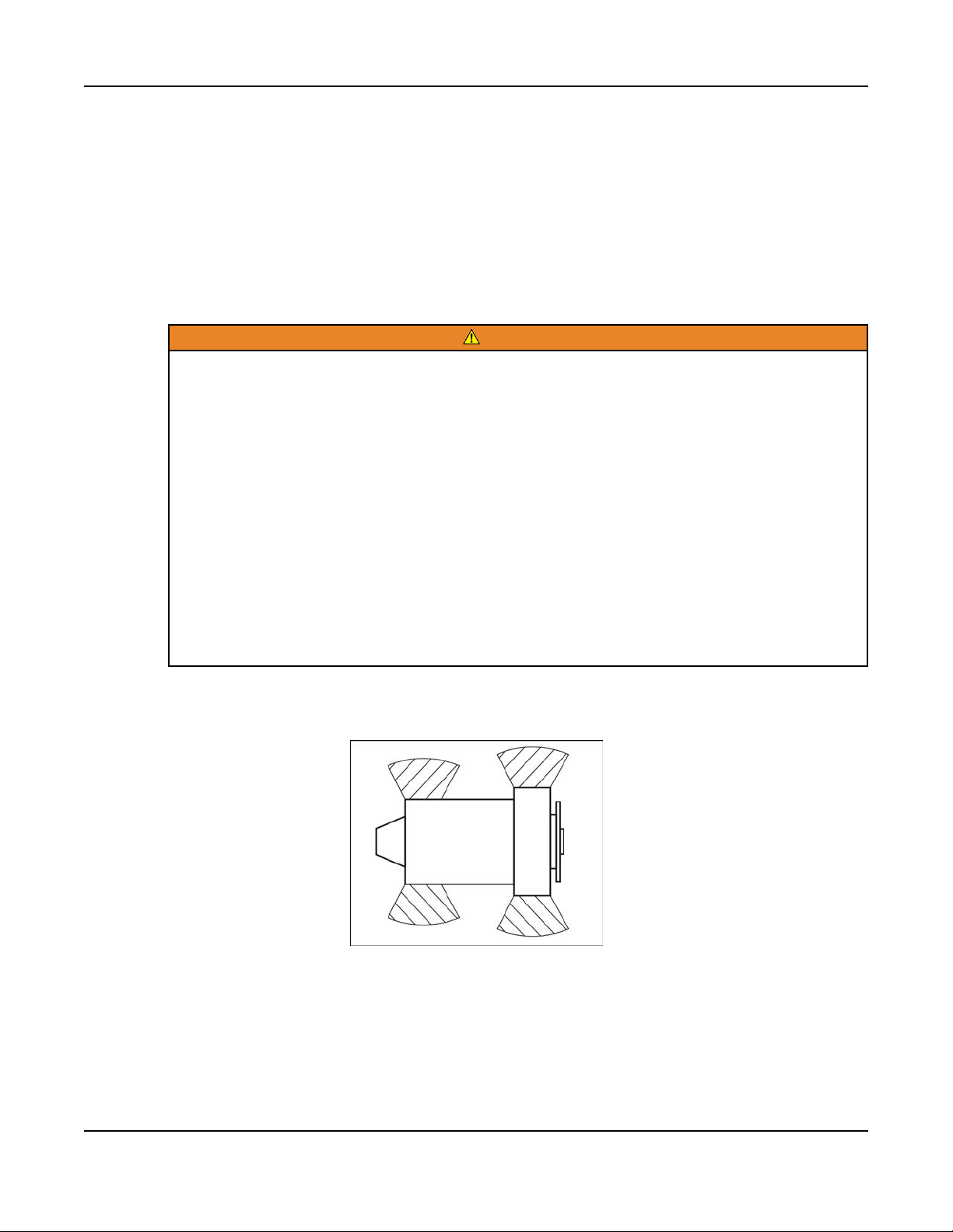
Always wear suitable PPE when working in the hatched areas shown in the diagram
or directly in-line with any air inlet/outlet.
FIGURE 1. HATCHED AREAS
Make sure this consideration is captured in your risk assessment.
5A053X177 (Issue 6) Copyright © 2017 Cummins Inc.
Page 10

1. IMPORTANT SAFETY INSTRUCTIONS 6-2017
1.4 Electrical Shocks and Arc Flashes Can Cause Severe Personal Injury or Death
WARNING
Electric Shock Hazard
Voltages and currents present an electrical shock hazard that can cause
severe burns or death.
Contact with exposed energized circuits with potentials of 50 Volts AC or 75
Volts DC or higher can cause electrical shock and electrical arc flash. Refer
to standard NFPA 70E or equivalent safety standards in corresponding
regions for details of the dangers involved and for the safety requirements.
Guidelines to follow when working on de-energized electrical systems:
• Use proper PPE. Do not wear jewelry and make sure that any conductive items
are removed from pockets as these items can fall into equipment and the
resulting short circuit can cause shock or burning. Refer to standard NFPA 70E
for PPE standards.
• De-energize and lockout/tagout electrical systems prior to working on them.
Lockout/Tagout is intended to prevent injury due to unexpected start-up of
equipment or the release of stored energy. Please refer to the lockout/tagout
section for more information.
• De-energize and lockout/tagout all circuits and devices before removing any
protective shields or making any measurements on electrical equipment.
• Follow all applicable regional electrical and safety codes.
Guidelines to follow when working on energized electrical systems:
NOTICE
It is the policy of Cummins Inc. to perform all electrical work in a deenergized state. However, employees or suppliers may be permitted to
occasionally perform work on energized electrical equipment only when
qualified and authorized to do so and when troubleshooting, or if deenergizing the equipment would create a greater risk or make the task
impossible and all other alternatives have been exhausted.
NOTICE
Exposed energized electrical work is only allowed as per the relevant
procedures and must be undertaken by a Cummins authorized person with
any appropriate energized work permit for the work to be performed while
using proper PPE, tools and equipment.
In summary:
• Do not tamper with or bypass interlocks unless you are authorized to do so.
6 A053X177 (Issue 6)Copyright © 2017 Cummins Inc.
Page 11

1. IMPORTANT SAFETY INSTRUCTIONS6-2017
• Understand and assess the risks - use proper PPE. Do not wear jewelry and
make sure that any conductive items are removed from pockets as these items
can fall into equipment and the resulting short circuit can cause shock or
burning. Refer to standard NFPA 70E for PPE standards.
• Make sure that an accompanying person who can undertake a rescue is
nearby.
AC Supply and Isolation
NOTICE
Local electrical codes and regulations (for example, BS EN 12601:2010
Reciprocating internal combustion engine driven generating sets) may
require the installation of a disconnect means for the generator set, either on
the generator set or where the generator set conductors enter a facility.
NOTICE
The AC supply must have the correct over current and earth fault protection
according to local electrical codes and regulations. This equipment must be
earthed (grounded).
It is the sole responsibility of the customer to provide AC power conductors for
connection to load devices and the means to isolate the AC input to the terminal
box; these must comply with local electrical codes and regulations. Refer to the
wiring diagram supplied with the generator set.
The disconnecting device is not provided as part of the generator set, and Cummins
accepts no responsibility for providing the means of isolation.
AC Disconnect Sources
WARNING
Hazardous Voltage
Contact with high voltages can cause severe electrical shock, burns, or
death.
The equipment may have more than one source of electrical energy.
Disconnecting one source without disconnecting the others presents a
shock hazard. Before starting work, disconnect the equipment, and verify
that all sources of electrical energy have been removed.
1.5 Fuel and Fumes Are Flammable
Fire, explosion, and personal injury or death can result from improper practices.
• Do not fill fuel tanks while the engine is running unless the tanks are outside
the engine compartment. Fuel contact with hot engine or exhaust is a potential
fire hazard.
7A053X177 (Issue 6) Copyright © 2017 Cummins Inc.
Page 12

1. IMPORTANT SAFETY INSTRUCTIONS 6-2017
• Do not permit any flame, cigarette, pilot light, spark, arcing equipment, or other
ignition source near the generator set or fuel tank.
• Fuel lines must be adequately secured and free of leaks. Fuel connection at the
engine should be made with an approved flexible line. Do not use copper piping
on flexible lines as copper will become brittle if continuously vibrated or
repeatedly bent.
• Make sure all fuel supplies have a positive shutoff valve.
• Make sure the battery area has been well-ventilated prior to servicing near it.
Lead-acid batteries emit a highly explosive hydrogen gas that can be ignited by
arcing, sparking, smoking, etc.
Gaseous Fuels
Natural gas is lighter than air, and will tend to gather under covered areas. Propane
is heavier than air, and will tend to gather in sumps or low areas. NFPA code
requires all persons handling propane to be trained and qualified.
Do Not Operate in Flammable and Explosive Environments
Flammable vapor can cause an engine to over speed and become difficult to stop,
resulting in possible fire, explosion, severe personal injury, and death. Do not
operate a generator set where a flammable vapor environment can be created,
unless the generator set is equipped with an automatic safety device to block the air
intake and stop the engine. The owners and operators of the generator set are
solely responsible for operating the generator set safely. Contact your authorized
Cummins distributor for more information.
1.6 Exhaust Gases Are Deadly
• Provide an adequate exhaust system to properly expel discharged gases away
from enclosed or sheltered areas, and areas where individuals are likely to
congregate. Visually and audibly inspect the exhaust system daily for leaks per
the maintenance schedule. Make sure that exhaust manifolds are secured and
not warped. Do not use exhaust gases to heat a compartment.
• Make sure the unit is well ventilated.
Exhaust Precautions
WARNING
Hot Exhaust Gases
Contact with hot exhaust gases can cause severe burns.
Wear personal protective equipment when working on equipment.
8 A053X177 (Issue 6)Copyright © 2017 Cummins Inc.
Page 13
1. IMPORTANT SAFETY INSTRUCTIONS6-2017
WARNING
Hot Surfaces
Contact with hot surfaces can cause severe burns.
The unit is to be installed so that the risk of hot surface contact by people is
minimized. Wear appropriate PPE when working on hot equipment and avoid
contact with hot surfaces.
WARNING
Toxic Gases
Inhalation of exhaust gases can cause asphyxiation and death.
Pipe exhaust gas outside and away from windows, doors, or other inlets to
buildings. Do not allow exhaust gas to accumulate in habitable areas.
WARNING
Fire Hazard
Contaminated insulation is a fire hazard. Fire can cause severe burns or
death.
Remove any contaminated insulation and dispose of it in accordance with
local regulations.
The exhaust outlet may be sited at the top or bottom of the generator set. Make
sure that the exhaust outlet is not obstructed. Personnel using this equipment must
be made aware of the exhaust position. Position the exhaust away from flammable
materials - in the case of exhaust outlets at the bottom, make sure that vegetation is
removed from the vicinity of the exhaust.
The exhaust pipes may have some insulating covers fitted. If these covers become
contaminated they must be replaced before the generator set is run.
To minimize the risk of fire, make sure the following steps are observed:
• Make sure that the engine is allowed to cool thoroughly before performing
maintenance or operation tasks.
• Clean the exhaust pipe thoroughly.
1.7 The Hazards of Carbon Monoxide
Carbon monoxide (CO) is an odorless, colorless, tasteless and non-irritating gas.
You cannot see it or smell it. Red blood cells, however, have a greater affinity for
CO than for oxygen. Therefore, exposure even to low levels of CO for a prolonged
period can lead to asphyxiation (lack of oxygen) resulting in death. Mild effects of
CO poisoning include eye irritation, dizziness, headaches, fatigue and the inability to
think clearly. More extreme symptoms include vomiting, seizures and collapse.
Engine-driven generator sets produce harmful levels of carbon monoxide that can
injure or kill you.
9A053X177 (Issue 6) Copyright © 2017 Cummins Inc.
Page 14

1. IMPORTANT SAFETY INSTRUCTIONS 6-2017
Special Risks of CO near the Home
WARNING
Toxic Gases
Carbon monoxide (CO) gas can cause nausea, fainting, or death. Residents
can be exposed to lethal levels of CO when the generator set is running.
Depending on air temperature and wind, CO can accumulate in or near the
home.
To protect yourself and others from the dangers of CO poisoning, it is
recommended that reliable, approved, and operable CO detector alarms are
installed in proper locations in the home as specified by their manufacturer.
Protecting Yourself from CO Poisoning
• Locate the generator set in an area where there are no windows, doors, or
other access points into the home.
• Make sure all CO detectors are installed and working properly.
• Pay attention for signs of CO poisoning.
• Check the exhaust system for corrosion, obstruction, and leaks every time you
start the generator set and every eight hours when you run it continuously.
1.8 Earth Ground Connection
The neutral of the generator set may be required to be bonded to earth ground at
the generator set location, or at a remote location, depending on system design
requirements. Consult the engineering drawings for the facility or a qualified
electrical design engineer for proper installation.
NOTICE
The end user is responsible to make sure that the ground connection point
surface area is clean and free of rust before making a connection.
NOTICE
The end user is responsible for making sure that an earthing arrangement
that is compliant with local conditions is established and tested before the
equipment is used.
10 A053X177 (Issue 6)Copyright © 2017 Cummins Inc.
Page 15
2 Introduction
Hazardous Voltage
Contact with high voltages can cause severe electrical shock, burns, or
death.
Make sure that only a trained and experienced electrician makes generator
set electrical output connections, in accordance with the installation
instructions and all applicable codes.
Electrical Generating Equipment
Faulty electrical generating equipment can cause severe personal injury or
death.
Generator sets must be installed, certified, and operated by trained and
experienced person in accordance with the installation instructions and all
applicable codes.
WARNING
WARNING
2.1 About This Manual
This manual provides troubleshooting and repair information for the generator sets
listed on the front cover.
The information contained within the manual is based on information available at the
time of going to print. In line with the Cummins Inc. policy of continuous
development and improvement, information may change at any time without notice.
The users should therefore make sure that before commencing any work, they have
the latest information available. The latest version of this manual is available on
QuickServe Online (https://quickserve.cummins.com).
This manual does not include instructions for servicing printed circuit board
assemblies. After determining that a printed circuit board assembly is faulty, replace
it. Do not repair it. Attempts to repair a printed circuit board can lead to costly
damage to the equipment.
This manual contains basic (generic) wiring diagrams and schematics that are
included to help in troubleshooting. The wiring diagrams and schematics that are
maintained with the unit should be updated when modifications are made to the
unit.
Operating and basic maintenance instructions are in the applicable generator set
operator manual. Read and carefully observe all instructions and precautions in this
manual.
11A053X177 (Issue 6) Copyright © 2017 Cummins Inc.
Page 16

2. Introduction 6-2017
2.2 Test Equipment
To perform the test procedures in this manual, the following test equipment must be
available:
• True RMS (Root Mean Square) meter for accurate measurement of small AC
and DC voltages
• Grounding wrist strap to prevent circuit board damage due to electrostatic
discharge (ESD)
• Wheatstone bridge or digital ohmmeter
• Load bank
• Megger or insulation resistance meter
2.3 Schedule of Abbreviations
This list is not exhaustive. For example, it does not identify units of measure or
acronyms that appear only in parameters, event/fault names, or part/accessory
names.
Abbr. Description Abbr. Description
AC Alternating Current LED Light-Emitting Diode
AMP AMP, Inc. (part of Tyco
Electronics)
ANSI American National
Standards Institute
ASOV Automatic Shut Off Valve MPU Magnetic Pickup
ASTM American Society for
Testing and Materials
(ASTM International)
ATS Automatic Transfer
Switch
AVR Automatic Voltage
Regulator
AWG American Wire Gauge NO Normally Open
CAN Controlled Area Network NWF Network Failure
CB Circuit Breaker OEM Original Equipment
MFM Multifunction Monitor
Mil Std Military Standard
NC Normally Closed
NC Not Connected
NFPA National Fire Protection
Agency
Manufacturer
CE Conformité Européenne OOR Out Of Range
CCA Cold Cranking Ampere OORH/
ORH
12 A053X177 (Issue 6)Copyright © 2017 Cummins Inc.
Out Of Range High
Page 17

Abbr. Description Abbr. Description
CFM Cubic Feet per Minute OORL/ORL Out Of Range Low
2. Introduction6-2017
CGT Cummins Generator
PB Push Button
Technologies
CMM Cubic Meters per Minute PCC PowerCommand®Control
CT Current Transformer PGI Power Generation
Interface
DC Direct Current PGN Parameter Group
Number
DEF Diesel Exhaust Fluid PI Proportional/Integral
DPF Diesel Particulate Filter PID Proportional/Integral/
Derivative
EBS Excitation Boost System PLC Programmable Logic
Controller
ECM Engine Control Module PMG Permanent Magnet
Generator
ECS Engine Control System PPE Personal Protective
Equipment
EMI Electromagnetic
PT Potential Transformer
Interference
EN European Standard PTC Power Transfer Control
EPS Engine Protection
PWM Pulse-Width Modulation
System
E-Stop Emergency Stop RFI Radio Frequency
Interference
FAE Full Authority Electronic RH Relative Humidity
FMI Failure Mode Identifier RMS Remote Monitoring
System
FSO Fuel Shutoff RMS Root Mean Square
Genset Generator Set RTU Remote Terminal Unit
GCP Generator Control Panel SAE Society of Automotive
Engineers
GND Ground scfh Standard Cubic Feet of
gas per Hour
HMI Human-Machine
Interface
SCR Selective Catalytic
Reduction
13A053X177 (Issue 6) Copyright © 2017 Cummins Inc.
Page 18
2. Introduction 6-2017
Abbr. Description Abbr. Description
IC Integrated Circuit SPN Suspect Parameter
Number
ISO International Organization
for Standardization
LBNG Lean-Burn Natural Gas UL Underwriters
LCD Liquid Crystal Display UPS Uninterruptible Power
LCT Low Coolant
Temperature
2.4 Related Literature
Before any attempt is made to operate the generator set, the operator should take
time to read all of the manuals supplied with the generator set and familiarize
themselves with the warnings and operating procedures.
A generator set must be operated and maintained properly if you are to
expect safe and reliable operation. The Operator manual includes a
maintenance schedule and a troubleshooting guide.
The Health and Safety manual must be read in conjunction with this manual
for the safe operation of the generator set, as well as the Warranty
Statements.
SW_B+ Switched B+
Laboratories
Supply
NOTICE
The literature provided with the generator set is as follows:
• Installation Manual (A053X172)
• Operator Manual (A053X174)
• Quick Start Installation Guide (A053X181)
• Quick Start Operator Guide (A053X183)
• Health and Safety Manual (0908-0110-00)
• Global Warranty Statement (A056F206)
• Emission Warranty Statement (Federal Emissions EPA Title 40 CFR Part 90
Component Warranty) (A028X278)
The relevant manuals appropriate to your generator set are also available. The
documents below are in English:
• Generator Set Service Manual (A053X177)
• RA Series RA112L1 Automatic Transfer Switch Owner Manual (A052S254) - if
applicable
14 A053X177 (Issue 6)Copyright © 2017 Cummins Inc.
Page 19
• RA Series 100A/200A/400A Automatic Transfer Switch Owner Manual
(A046S594) - if applicable
• Parts Manual (A053X179)
• Standard Repair Times - HO Family (A053X186)
• Service Tool Manual (A043D529)
• Warranty Failure Code Manual (F1115C)
• Engineering Application Manual T-030: Liquid Cooled Generator Sets
(A040S369)
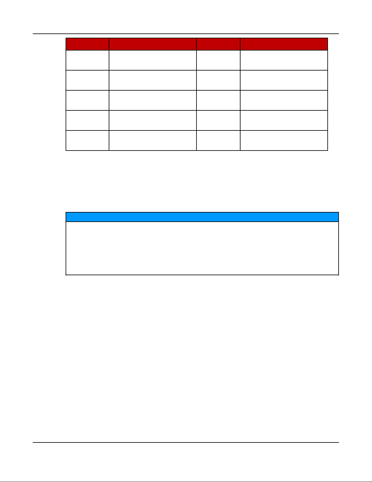
2.5 Model Specifications
TABLE 1. MODEL VARIATIONS
2. Introduction6-2017
Model
C13N6H Both 13 54.2
C17N6H Both 17 70.8
C20N6H,
C20N6HC
Maximum load imbalance allowed is 50% of generator set rating.
TABLE 2. COLD WEATHER SPECIFICATIONS (ALL MODELS)
Temperature Description
Above 4 °C (40 °F) No starting aids required
-17 to 4 °C (0 to 40 °F) Alternator and regulator heaters (supplied with the generator set)
Natural Gas or
Propane Vapor
Natural Gas Only 18 75
Propane Vapor
Only
kW Amps Frequency Voltage
20 83.3
NOTICE
60 Hz
120/240 VAC
Single Phase
Below -17 °C (0 °F)
• Alternator and regulator heaters
• 0W30 oil (see the oil recommendation below)
• Extreme cold weather kit (A045B984) (includes battery and
oil heaters)
15A053X177 (Issue 6) Copyright © 2017 Cummins Inc.
Page 20
2. Introduction 6-2017
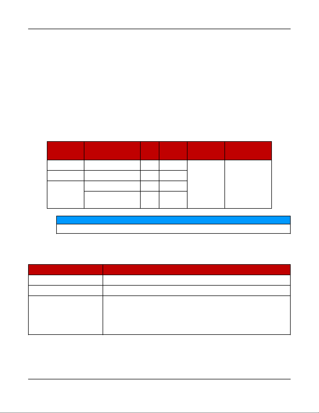
TABLE 3. FUEL SPECIFICATIONS (AT FULL LOAD) (ALL MODELS)
C13N6H C17N6H C20N6H, C20N6HC
Type
scfh BTU/hr scfh BTU/hr scfh BTU/hr
Natural Gas 253 260,000 289 297,000 300 309,000
Propane 85 212,000 101 252,000 116 290,000
Natural Gas: 3.5 - 12 inch water column (0.9 - 3.0 kPa)
Fuel Pressure
Propane Vapor: 1.5 - 3.0 kPa (6 - 12 inch water column)
Maximum pressure for either fuel under any condition: 3.2 kPa (13
inch water column)
TABLE 4. ENGINE SPECIFICATIONS (ALL MODELS)
Type Value
Engine
2 cylinder v-twin, OHV, air-cooled, 4-stroke, spark
ignited
Displacement 999 cc (60.9 in3)
Spark Plug Gap 0.7 - 0.8 mm (0.027 - 0.031 in)
Spark Plug Torque (Cold Engine) 25 - 30 Nm (18 - 22 ft-lb)
RPM 3600
Lubricating Oil Pressure at Rated
Speed (Minimum)
310 kPa (45 psi)
Full synthetic gasoline engine oil which meets or
exceeds API service SN/SN-RC and ILSAC GF-5:
Oil Recommendation
• 5W30: Temperatures above -17 °C (0 °F)
• 0W30: All temperatures, required below -17 °C (0
°F)
Lubricating Oil Capacity:
Lubricating Oil Pressure at Rated
Speed (Minimum)
310 kPa (45 psi)
--Full at High Mark on Dipstick 2.3 L (2.4 qt)
--Low Mark on Dipstick 1.3 L (1.4 qt)
16 A053X177 (Issue 6)Copyright © 2017 Cummins Inc.
Page 21
Model
2. Introduction6-2017
TABLE 5. GENERATOR SET SIZE (ALL MODELS)
Dimension Value
Length 865 mm (34.1 in)
Width 915 mm (36 in)
Height 694 mm (27.3 in)
TABLE 6. GENERATOR SET WET WEIGHT (INCLUDING BATTERY)
Model Value
C13N6H 218 kg (479 lb)
C17N6H, C20N6H, C20N6HC 241 kg (531 lb)
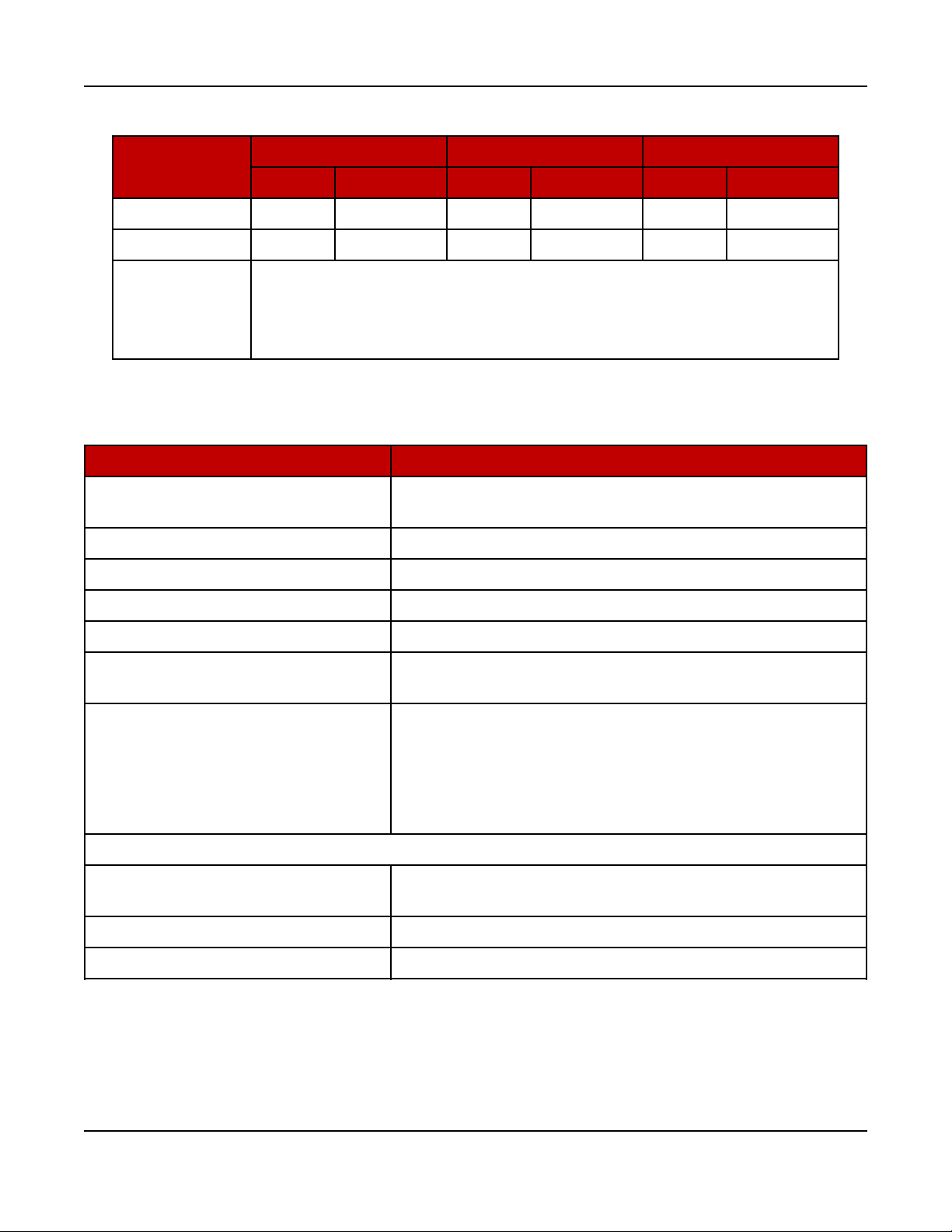
TABLE 7. GENERATOR SET DERATING GUIDELINES
Engine Power Available Up To... Derate At…
Elevation Ambient Temperature Elevation Temperature
C13N6H 2100 m (6900 ft) 25 °C (77 °F)
C17N6H 300 m (1000 ft) 25 °C (77 °F)
C20N6H,
C20N6HC
0 m (0 ft) 15 °C (60 °F)
NOTICE
Derating guidelines: This product's output power is limited by factors such
as BTU content of fuel, ambient temperature, altitude, humidity, engine
condition, etc. The derating guidelines are based on properly maintained
product, using the appropriate fuel. Derate values are based on expected
engine power changes from elevation and temperatures listed.
TABLE 8. ALTERNATOR SPECIFICATIONS (ALL MODELS)
Type Specification
Design Rotating field
Poles 2
3.5% per
300 m
(1000 ft)
1% per
5.5 °C (10 °F)
RPM 3600
Voltage 240
Hz 60
17A053X177 (Issue 6) Copyright © 2017 Cummins Inc.
Page 22
2. Introduction 6-2017
TABLE 9. CONTROL SPECIFICATIONS (ALL MODELS)
Control
Integrated Microprocessor-Based Engine, Alternator, Transfer Switch Controller
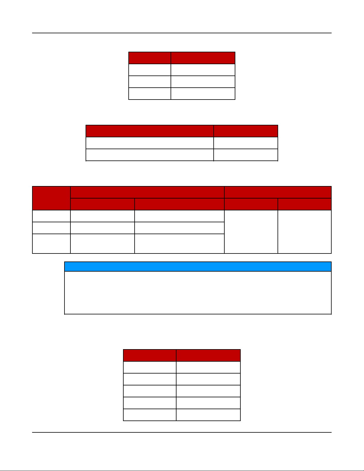
TABLE 10. DC SYSTEM SPECIFICATIONS (ALL MODELS)
Type Value
Nominal Battery Voltage 12 VDC
Battery Group 51 R
Battery Type Lead Acid
Minimum Cold Crank Amps (CCA) 450
2.6 After Sales Services
Cummins offers a full range of maintenance and warranty services.
Maintenance
WARNING
Electrical Generating Equipment
Incorrect service or parts replacement can result in severe personal injury,
death, and/or equipment damage.
Make sure service personnel are qualified to perform electrical and
mechanical service.
For expert generator set service at regular intervals, contact your Cummins Inc.
service provider. See power.cummins.com/sales-service-locator for service
locations that service this application. Maintenance tasks should only be undertaken
by trained and experienced technicians provided by your Cummins Inc. service
provider.
Warranty
For details of the warranty coverage for your generator set, refer to the Global
Warranty Statement listed in the Related Literature section.
In the event of a breakdown, prompt assistance can normally be given by factory
trained service technicians with facilities to undertake all minor and many major
repairs to equipment on site.
Extended warranty coverage is also available.
For further warranty details, contact your authorized service provider.
18 A053X177 (Issue 6)Copyright © 2017 Cummins Inc.
Page 23

2. Introduction6-2017
NOTICE
Damage caused by failure to follow the manufacturer's recommendations
will not be covered by the warranty. Please contact your authorized service
provider.
Warranty Limitations
For details of the warranty limitations for your generator set, refer to the
warranty statement applicable to the generator set.
How to Obtain Service
When a product requires service, contact the nearest authorized Cummins Inc.
service provider. To locate the service provider, refer to power.cummins.com and
select Sales & Service Locator. When contacting the service provider, always
supply the complete model, specification, and serial number as shown on the
nameplate.
Service Technician Support
For technical support for service technicians, call 1-855-TECH711 (1-855-832-
4711) to reach the Channel One Technical Support Hotline in the United
States or Canada. Distributors should contact their Cummins Inc. service
contact.
Fuel Information Needed for Service Issue
When servicing is needed on a failed fuel tank, the following questions must
be answered and conveyed via the submission of the Technical Support
Request form (TSR).
1. Is there an actual confirmed leak?
• Has the rupture basin alarm gone off?
• What Fault Code(s) are present?
• Is the sensor functioning properly?
• Is there visible fuel in the basin or outside the tank (i.e. is there an
EPA concern)?
• If so, what is the leak rate?
• Is the fluid fuel and NOT water?
• What is the level of the fuel, in inches, in the tank and basin? A
dipstick may be required to obtain an accurate reading.
• Can the leak locale be identified?
19A053X177 (Issue 6) Copyright © 2017 Cummins Inc.
Page 24
2. Introduction 6-2017
CAUTION
High Pressure
Excessive pressurization can rupture tanks or basins which
can result in severe personal injury or death.
Remove all liquids before pressure testing. Do not exceed 2
psig when testing a tank or basin.
• Has the tank been previously repaired?
• Is there evidence of physical damage that may be contributing to the
leak?
• Pictures may convey a great deal of information and should be
considered.
2. What are the CPG and manufacturer's details associated with the tank?
Include the following in the Issue:
• CPG part number.
• Manufacturer's part number, model, serial number and date of
manufacture.
3. What time frame is required for the needed repair or replacement (i.e.
how sensitive of an issue is this with the client and do they have any
flexibility in the repair timing)?
• If replacement, has there been an order placed for a new tank?
• If ordered, is it categorized as machine down?
• If not, then please update the order accordingly.
• If an order has been placed, the Issue is to reflect this data (order
number) as well.
Obtaining Information Needed for Fuel Tank Service Issues
CAUTION
High Pressure
Excessive pressurization can rupture tanks or basins which can result
in severe personal injury or death.
Remove all liquids before pressure testing. Do not exceed 2 psig when
testing a tank or basin.
To aid in identifying/isolating the leak or obtaining some of the information
needed for Fuel Tank Service Issues:
1. Seal all penetrations/fittings with plugs except for one.
2. For the remaining penetration, fit up a regulated pressure source with a
calibrated pressure gauge and a pressure relief valve (set to no more
than 2.5 psig).
20 A053X177 (Issue 6)Copyright © 2017 Cummins Inc.
Page 25

2. Introduction6-2017
3. Pressurize the tank or basin to 2 psig and observe for the following:
• For secondary tank (basin) work, spray all exterior weld seams with a
soap water solution. Observe the pressure gauge for no change in a
30 minute period and visually observe the exterior seams for
bubbling. Results are to be conveyed in the Issue details.
• For the primary fuel tank, spray all exterior weld seams with a soap
water solution. Observe the pressure gauge for no change in a 30
minute period and visually inspect the interior of the basin to the
maximum extent possible. Results are to be conveyed in the Issue
details.
NOTICE
For further questions or concerns regarding the information stated
above, please contact (in the following order):
1. Your local Service Manager
2. DFSE-Counterpart
3. The Cummins Distributor Technical Support Line (1-812-377-6517)
21A053X177 (Issue 6) Copyright © 2017 Cummins Inc.
Page 26

2. Introduction 6-2017
Manufacturing Facilities
Facility Address Phone Numbers
U.S. and
CANADA
EMEA, CIS Cummins Inc.
ASIA
PACIFIC
Cummins Inc.
1400 73rd Ave. NE
Minneapolis, MN 55432 USA
Columbus Avenue
Manston Park
Manston, Ramsgate
Kent CT12 5BF
United Kingdom
Cummins Inc.
Royal Oak Way South
Daventry
Northamptonshire
NN11 8NU
United Kingdom
Cummins Inc.
10 Toh Guan Road #07-01
TT International Tradepark
Singapore 608838
Toll Free 1-800-CUMMINS
(1-800-286-6467)
Phone +1 763-574-5000
Fax +1 763-574-5298
Phone +44 1843 255000
Fax +44 1843 255902
Phone +44 1843 255000
Fax +44 1843 255902
Phone +65 6417 2388
Fax +65 6417 2399
BRAZIL Rua Jati, 310, Cumbica
Guarulhos, SP 07180-900
Brazil
CHINA Cummins Inc.
2 Rongchang East Street,
Beijing Economic – Technological
Development Area
Beijing 100176, P.R. China
INDIA Cummins Inc.
Power Generation Business Unit,
Plot No B-2, SEZ Industrial Area,
Village-Nandal & Surwadi, Taluka- Phaltan
Dist- Satara, Maharashtra 415523
India
LATIN
AMERICA
3350 Southwest 148th Ave.
Suite 205
Miramar, FL 33027 USA
Phone +55 11 2186 4195
Fax +55 11 2186 4729
Phone 86 10 59023001
Fax +86 10 5902 3199
Phone
+91 021 66305514
Phone +1 954 431 551
Fax +1 954 433 5797
22 A053X177 (Issue 6)Copyright © 2017 Cummins Inc.
Page 27

Facility Address Phone Numbers
MEXICO Eje 122 No. 200 Zona Industrial
San Luis Potosi, S.L.P. 78395
Phone +52 444 870 6700
Fax +52 444 824 0082
Mexico
2. Introduction6-2017
23A053X177 (Issue 6) Copyright © 2017 Cummins Inc.
Page 28

2. Introduction 6-2017
This page is intentionally blank.
24 A053X177 (Issue 6)Copyright © 2017 Cummins Inc.
Page 29

3 Startup
3.1 "Establishing Communications" Message
NOTICE
Once the battery is connected to the generator set and any display button is
pressed, the local display shows an "establishing communications"
message for approximately 5 seconds. (This may take longer if the signal
integrity is poor between the control and display due to a bad wire or
Electro-Magnetic Interference [EMI].) Once communication is established,
the display shows the HOME screen.
The “establishing communications” message will also be displayed
whenever the control is brought out of “sleep” mode by pressing any button
on the display. Sleep mode is entered after 30 minutes without utility or
generator set power to preserve battery energy since the battery charger will
not have AC power. The 30-minute timer is reset with any button press on
the display.
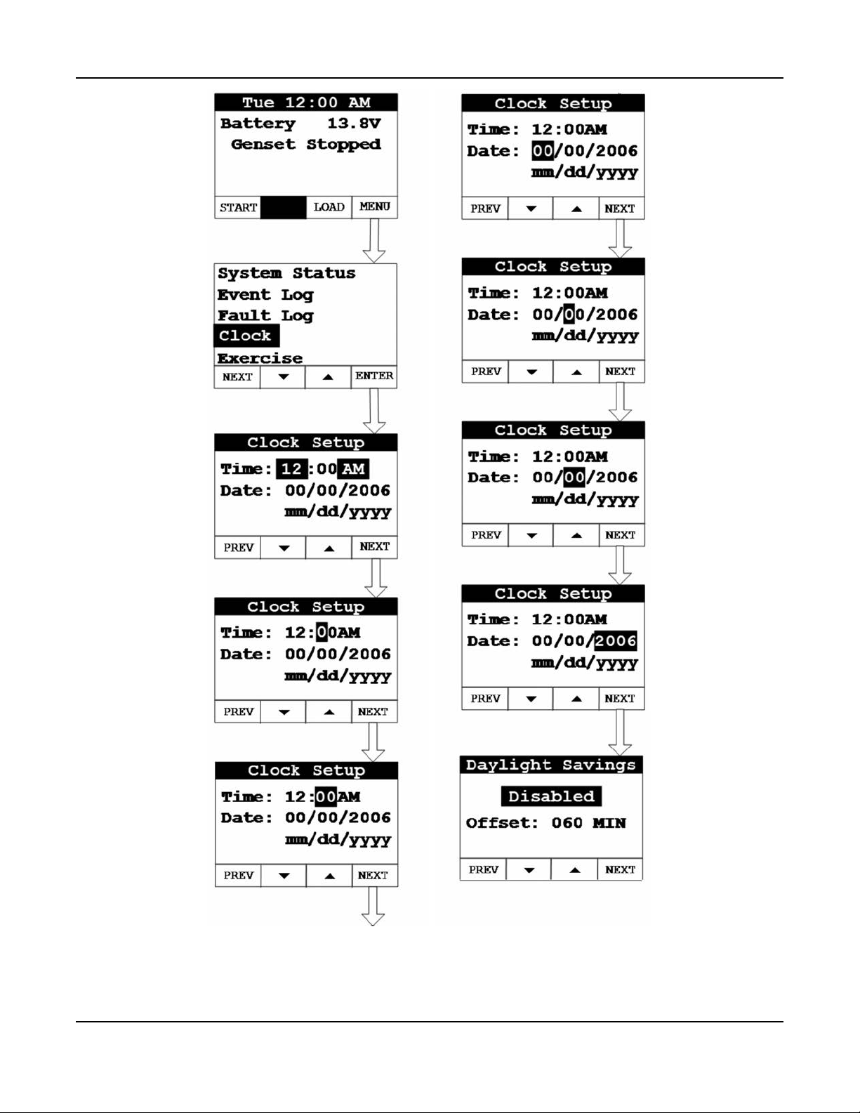
3.2 "Clock Setup" Screen
The Clock needs to be reset whenever the battery power is lost or
disconnected, or the control has entered “sleep” mode. Sleep mode is
entered after 30 minutes without utility or generator set power to preserve
battery energy since the battery charger will not have AC power. The 30minute timer is reset with any button press on the display.
The optional Remote Monitoring System (RMS) uses the generator set's
clock. The clock must be set accurately for the RMS to function properly.
To set up the generator set clock for the current date and time:
1. From the Main screen, select Menu.
2. Use the arrow keys to highlight Clock. Select the Enter key.
3. Use the arrow keys to set the time and date.
NOTICE
NOTICE
25A053X177 (Issue 6) Copyright © 2017 Cummins Inc.
Page 30
3. Startup 6-2017
FIGURE 2. CLOCK SETUP SCREEN
4. Select the Next key to go to the Daylight Savings screen.
26 A053X177 (Issue 6)Copyright © 2017 Cummins Inc.
Page 31

3. Startup6-2017
5. Use the arrow keys to enable/disable Daylight Savings. If enabling, select the
Next key to highlight the Offset field.
FIGURE 3. DAYLIGHT SAVINGS TIME (ENABLED)
6. Use the arrow keys and Next key to set the offset value for Daylight Savings
time.
27A053X177 (Issue 6) Copyright © 2017 Cummins Inc.
Page 32

3. Startup 6-2017
FIGURE 4. OFFSET VALUE
7. Select the Next key to go the screen that is used to set up when Daylight
Savings should start. Use the arrow keys and Next key to set Month (1 – 12),
Week (0 – 5), Day (Sun – Sat) and Hour (12AM – 12PM).
28 A053X177 (Issue 6)Copyright © 2017 Cummins Inc.
Page 33

3. Startup6-2017
FIGURE 5. DAYLIGHT SAVINGS TIME (START TIME SETUP)
8. Select the Next key to go the screen that is used to set up when Daylight
Savings should end. Use the arrow keys and Next key to set Month (1 – 12),
Week (0 – 5), Day (Sun – Sat) and Hour (12AM – 12PM).
29A053X177 (Issue 6) Copyright © 2017 Cummins Inc.
Page 34

3. Startup 6-2017
FIGURE 6. DAYLIGHT SAVINGS TIME (END TIME SETUP)
9. Keep selecting the Back button to save the settings and return to the main
screen.
30 A053X177 (Issue 6)Copyright © 2017 Cummins Inc.
Page 35

3.3 "Exercise" Screen
When installing an RA series transfer switch, follow these steps to configure the
Exercise mode in the generator set's local display or remote display.
Exercise settings need to be reset whenever battery power is lost or
disconnected, or the control has entered “sleep” mode.
Sleep mode is entered after 30 minutes without utility or generator set power
to preserve battery energy since the battery charger will not have AC power.
The 30-minute timer is reset with any button press on the display.
To set up the exercise function:
1. From the Main screen, select Menu.
2. Use the arrow keys to highlight Exercise. Select the Enter key.
3. Startup6-2017
NOTICE
NOTICE
NOTICE
If the time and date have not been set, a pop-up will appear that says,
"Set Valid Date and Time".
3. Use the arrow keys to enable or disable the Crank Exercise feature. Select
the Next key to go to the Exercise Time field. See the Exercise Sequences
section in the operator manual for more information.
NOTICE
When the Crank Exercise feature is enabled, an exercise command will
cause the engine starter to engage and rotate the engine, but will not
allow the engine to start. This feature allows the control system to
monitor critical generator set systems without running the engine. When
Crank Exercise is enabled, the generator set's exercising will alternate
between the Crank Exercise sequence and the normal exercise sequence
(that is, engine running) at scheduled times.
4. Use the arrow keys to set how long the generator set will exercise (from 1 to 20
minutes). Select the Next key to go to the Exercise field. The Exercise Sched
screen appears.
5. Use the arrow keys to set how often the generator set will exercise. The
frequency selections are:
• Weekly
• Bimonthly
• Monthly
31A053X177 (Issue 6) Copyright © 2017 Cummins Inc.
Page 36

3. Startup 6-2017
• Never
Select the Next key to go to the date and time fields.
6. Use the arrow keys to set the day and time the generator set will be exercised.
Select the Next key to highlight the Exercise Now field.
7. Select either arrow key to start the Exercise Now function.
NOTICE
Initiating the Exercise Now function will cause the generator set to start
immediately and run for the amount of time indicated by the Exercise
Time field, or run the Crank Exercise sequence. The ATS does not
transfer to generator power during exercise mode. Normally scheduled
exercise events will occur after the completion of the immediate exercise
event.
8. Keep selecting the Back button to save the settings and return to the Main
screen.
32 A053X177 (Issue 6)Copyright © 2017 Cummins Inc.
Page 37

3. Startup6-2017
FIGURE 7. EXERCISE SETUP SCREEN
33A053X177 (Issue 6) Copyright © 2017 Cummins Inc.
Page 38

3. Startup 6-2017
3.4 "Brightness and Contrast" Screen
To adjust the brightness and contrast of the display:
1. From the Main screen, select Menu.
2. Use the arrow keys to highlight Display Setup. Select the Enter key.
3. Use the arrow keys to set brightness and contrast for the display.
4. Keep selecting the Back button to save the settings and return to the Main
screen.
34 A053X177 (Issue 6)Copyright © 2017 Cummins Inc.
Page 39

3. Startup6-2017
FIGURE 8. BRIGHTNESS AND CONTRAST SCREEN
35A053X177 (Issue 6) Copyright © 2017 Cummins Inc.
Page 40

3. Startup 6-2017
3.5 "About" Screen
To retrieve information about the display:
1. From the Main screen, select Menu.
2. Use the arrow keys to highlight About. Select the Enter key.
36 A053X177 (Issue 6)Copyright © 2017 Cummins Inc.
Page 41

3. Startup6-2017
FIGURE 9. ABOUT SCREEN
37A053X177 (Issue 6) Copyright © 2017 Cummins Inc.
Page 42

3. Startup 6-2017
3.6 "Event Log" Screen
To retrieve information from the Event Log:
1. From the Main screen, select Menu.
2. Use the arrow keys to highlight Event Log. Select the Enter key.
3. Use the arrow keys to navigate through the Event Log.
4. Keep pressing the Back button to return to the Main screen.
FIGURE 10. EVENT LOG SCREEN
38 A053X177 (Issue 6)Copyright © 2017 Cummins Inc.
Page 43

3.7 "Fault Log" Screen
To retrieve information from the Fault Log:
1. From the Main screen, select Menu.
2. Use the arrow keys to highlight Fault Log. Select the Enter key.
3. Scroll through the fault log using the up and down double-arrows. Each screen
provides a brief description of the fault, the fault code number, the engine hours
and the time and date of the fault.
If there are no faults recorded, the “No Stored Faults" screen will appear.
4. Keep pressing the Back button to return to the Main screen.
3. Startup6-2017
NOTICE
39A053X177 (Issue 6) Copyright © 2017 Cummins Inc.
Page 44

3. Startup 6-2017
FIGURE 11. FAULT LOG SCREEN
3.8 "System Status" Screen
To retrieve system status:
1. From the Main screen, select Menu.
2. Use the arrow keys to highlight System Status. Select the Enter key.
3. Keep pressing the Back button to return to the Main screen.
40 A053X177 (Issue 6)Copyright © 2017 Cummins Inc.
Page 45

3. Startup6-2017
FIGURE 12. SYSTEM STATUS SCREEN
3.9 "Mode" Screen
To prevent unexpected starts from remote devices, disable Remote mode
and disconnect the connector on the back of the local display wired to any
remote mounted displays.
When Remote is set to Enabled via the local display, the “Remote On” LED on the
front of the display will illuminate indicating that the control will accept start
commands from remote displays or remote monitoring systems including a web
page or cell phone app.
WARNING
41A053X177 (Issue 6) Copyright © 2017 Cummins Inc.
Page 46

3. Startup 6-2017
NOTICE
The Remote function can only be activated (that is, enabled) from the local
display.
When Standby is on or set to Enabled, the “Standby On” LED on the front of the
display will illuminate indicating the control will start the generator set in response to
a utility power outage. Standby can be turned on at the local display. It can also be
enabled with a remote display, web page, or a cell phone app if Remote has already
been enabled at the local display. The Standby function cannot be enabled
remotely unless the Remote function is on. A manual Start or Stop event will disable
the Standby function. (If the manual Stop event is performed at the local display, the
Remote mode will also be disabled.)
1. To enable or disable the Remote and Standby modes on the LOCAL display:
a. From any screen, select the Mode key to get to the Mode screen.
b. Use the arrow keys to enable or disable the Remote mode. Select the Next
key to go to the next screen.
c. Use the arrow keys to enable or disable the Standby mode.
NOTICE
Whenever Standby is enabled, the Remote mode will also
automatically be enabled.
d. Keep pressing the Back button to save the settings and return to the Main
screen.
42 A053X177 (Issue 6)Copyright © 2017 Cummins Inc.
Page 47

3. Startup6-2017
FIGURE 13. MODE SETUP SCREEN (LOCAL DISPLAY)
2. To enable or disable the Standby mode on the REMOTE display:
NOTICE
Remote must be enabled before Standby mode can be changed from the
Remote display. If Remote mode is not enabled, Standby will remain
disabled and cannot be changed.
a. From any screen, select the Mode key to get to the Mode screen.
b. Use the arrow keys to enable or disable the Standby mode.
c. Keep pressing the Back button to save the settings and return to the Main
screen.
FIGURE 14. MODE SETUP SCREEN (REMOTE DISPLAY)
43A053X177 (Issue 6) Copyright © 2017 Cummins Inc.
Page 48

3. Startup 6-2017
3.10 Automatic Load Management
NOTICE
The capability to automatically add or remove specific electrical loads from
the generator set requires that load management devices be wired to the
generator set load management outputs.
When the generator set is started automatically in Standby mode due to a loss of
utility or manually by the operator, the control will energize all four load
management outputs, disconnecting the associated loads from AC power. Once
the transfer switch transfers to generator set power, the generator set control will
evaluate the total load on the generator set versus a set point programmed into the
control (80% of rated).
If the generator set’s total load is below the set point, the generator set control will
sequentially add the highest priority managed load every three minutes. Managed
loads will continue to be added as long as the size of the next priority load to be
added won’t increase total generator set load above the set point. The control
measures and stores the size of each managed load in its memory. Load priorities
are in the following order:
• Priority #1: load control 1
• Priority #2: load control 2
• Priority #3: load control 3
• Priority #4: load control 4
If the load on the generator set is reduced at any time to below the set point, the
control will add the next highest priority managed load in three minutes provided it
does not increase the total generator set load above the set point.
If the load on the generator set exceeds 95% of its rating, the generator set control
will begin disconnecting the lowest managed priority loads in sequence every
second until the load on the generator set is below 95% of its rating.
Priority #1 load is always the first added and the last disconnected; therefore, it
should be wired to the managed load deemed most critical to the homeowner.
Priority #2 load cannot be added before priority #1 load, nor can it be disconnected
before priority #3 or #4, etc.
3.11 Startup
1. Verify that the installation was completed correctly.
2. Read the operator manual. Perform the pre-start checks as instructed.
3. Connect the battery cables to the battery with the positive (+) cable first.
Immediately cover the battery post and terminal with the red cover provided on
the battery cable.
44 A053X177 (Issue 6)Copyright © 2017 Cummins Inc.
Page 49

3. Startup6-2017
4. Although the generator set is shipped from the factory with the proper level of
engine oil, check the oil level before it is started.
5. Start and test the system.
6. Operate the generator set following all the instructions and precautions in the
operator manual.
NOTICE
Before leaving the site, if the generator set is ready to be placed in service,
enable the Remote and Standby modes from the local display.
NOTICE
Contact your local Cummins service provider if you encounter a fault code.
45A053X177 (Issue 6) Copyright © 2017 Cummins Inc.
Page 50

3. Startup 6-2017
This page is intentionally blank.
46 A053X177 (Issue 6)Copyright © 2017 Cummins Inc.
Page 51

4 Operation
4.1 Introduction
This section describes the operation of the generator set. The text should be read in
conjunction with the Control System section of this manual.
All indicators, control switches/buttons, and graphical display are located on the
face of the local and remote displays.
CAUTION
To avoid injury, be sure to read the instructions in the Operating the
Generator Set Cover Safely section before lifting the generator set cover.
4.2 General Operating Conditions
The area surrounding the generator set is critical for safety and its performance.
Follow the guidelines below.
• Do not stack anything on top of the generator set.
• Do not store anything inside of the generator set.
• Keep areas clear in front of the cool air in and hot air out (free of obstructions,
debris, plants, etc.).
NOTICE
All maintenance procedures must be performed or supervised by authorized
and trained service personnel only.
4.3 Generator Set Operation
WARNING
Combustible Vapors
Do not operate a generator set where there are or can be combustible
vapors.
These vapors can be sucked through the air intake system and cause engine
acceleration and overspeeding, which can result in a fire, an explosion,
personal injury and extensive property damage.
Correct care of your generator set will result in longer life, better performance, and
more economical operation.
47A053X177 (Issue 6) Copyright © 2017 Cummins Inc.
Page 52

4. Operation 6-2017
Cummins Inc. does not know how you will use your generator set. The equipment
owner and operator, therefore, is responsible for safe operation in the installation
site environment. Consult your authorized Cummins Inc. service provider for further
information.
Sequence of Operation
NOTICE
The following sequences are based on an approximate time duration. Your
generator set may vary slightly from the timing diagrams in this manual. All
referenced times are based on default control settings. The following
sequences are applicable to generator sets connected to a single phase RA
series transfer switch.
Auto Start Sequence (with an RA Series Transfer Switch)
NOTICE
Standby Mode must be enabled for Auto Start to execute.
In normal operation, utility power is provided through the transfer switch to the
building loads; the generator set is not running.
FIGURE 15. GENSET STOPPED
If utility power is not available (that is, there is a power outage), the following
sequence will be executed to connect building load to the generator set, and
then reconnect building load back to the utility power when it is available.
1. The generator set starts.
48 A053X177 (Issue 6)Copyright © 2017 Cummins Inc.
Page 53

4. Operation6-2017
FIGURE 16. GENSET STARTING
2. After the generator set reaches rated voltage and frequency, the transfer
switch transfers the building load to the generator set. The building's
electrical power is now provided by the generator set.
FIGURE 17. GENSET POWER
3. When utility power is restored, the sequence to transfer building load to
the utility begins.
4. The generator set continues to run and waits for utility power to stabilize.
49A053X177 (Issue 6) Copyright © 2017 Cummins Inc.
Page 54

4. Operation 6-2017
FIGURE 18. UTILITY RE-TRANS
5. When utility power is stable for 5 minutes, the transfer switch connects
the building load back to utility power.
FIGURE 19. UTILITY RETURNED
6. The generator set runs an additional 5 minutes to cool down and then
shuts off.
FIGURE 20. ENGINE COOLDOWN
7. Normal operation resumes. See Figure 15.
Exercise Sequences
1. Standard Exercise sequence:
NOTICE
Standby Mode must be enabled for standard exercise to execute.
50 A053X177 (Issue 6)Copyright © 2017 Cummins Inc.
Page 55

4. Operation6-2017
NOTICE
While the generator set is exercising, the building load remains
connected to the utility; it is not transferred to the generator set.
The following steps will be executed when the programmed exercise day
and time are reached or the Exercise Now option is selected and the
standard exercise sequence is run:
a. The generator set starts.
FIGURE 21. EXERCISE CYCLE STARTED
b. After the generator set reaches rated speed and voltage, the exercise
timer is started.
51A053X177 (Issue 6) Copyright © 2017 Cummins Inc.
Page 56

4. Operation 6-2017
FIGURE 22. EXERCISING
c. When the defined exercise time has completed, the generator set
stops and normal operation resumes.
FIGURE 23. EXERCISE CYCLE COMPLETED
2. Crank Only Exercise Sequence
NOTICE
Standby Mode must be enabled for Crank Exercise to execute.
When Crank Exercise is enabled, the generator set will alternate between
crank only exercise and standard (that is, generator set running) exercise
sequences.
The following steps will be executed when the programmed exercise day
and time are reached or the Exercise Now option is selected and the
crank only exercise sequence is run:
a. The generator set engine starter engages and rotates the engine, but
the engine does not start.
52 A053X177 (Issue 6)Copyright © 2017 Cummins Inc.
Page 57

4. Operation6-2017
b. The generator set engine starter cranks for 8 seconds, rests for 15
seconds, and cranks another 8 seconds if the generator set control
has not verified the information it is monitoring. Depending on the
outcome of this sequence, either a shutdown fault message is issued
or normal standby operation resumes.
FIGURE 24. CYCLE CRANK
4.4 Manual Start Sequence (Local)
NOTICE
If the utility power supply to the generator set's utility powered battery
charger is interrupted, the battery can become discharged due to parasitic
loads and the generator set may not start when needed. Whenever utility
power is interrupted and the generator set is not in Standby mode for any
reason (fuel preservation, etc.), start and run the generator set for 2 hours
every 24 hour period when temperatures are above 50 °F (10 °C), or every 9
hour period when temperatures are below 50 °F (10 °C).
The following steps will be executed when Manual Start is used at the local display:
1. If you do not want the ATS to transfer load to the generator set, open the
generator set mounted circuit breaker when doing a manual start.
2. From the Main screen, select the START key.
3. A second screen appears notifying the operator that Standby will be disabled.
Select the START key again to start the generator set.
53A053X177 (Issue 6) Copyright © 2017 Cummins Inc.
Page 58

4. Operation 6-2017
4. After the generator set reaches rated voltage and frequency, the transfer switch
transfers the building load to the generator set (unless the circuit breaker on the
generator set is "off"). The building's electrical power is now provided by the
generator set.
FIGURE 25. GENSET POWER
4.5 Manual Stop Sequence (Local)
The following steps will be executed when Manual Stop is selected at the Local
display:
1. Press the red STOP button on the local display. The generator set will stop
immediately and the building load will be transferred to the utility.
2. For normal operation to resume, Standby will need to be enabled. See the
section on enabling Standby Mode.
NOTICE
The red STOP button on the Local display, when pressed, will cause
both Remote and Standby Modes to be disabled.
4.6 Manual Start/Stop Sequence (Remote)
Remote mode must be enabled on the local display to allow manual start and stop
from the Remote display. The manual start and stop sequences are the same for
the Remote display and the Local display.
NOTICE
The red STOP button on the Remote display, when pressed, will cause the
Standby Mode to be disabled.
4.7 "Fault" and "New Event" Screens
Various fault and event screens may appear on the operator display.
"FAULT" SCREEN
54 A053X177 (Issue 6)Copyright © 2017 Cummins Inc.
Page 59

4. Operation6-2017
If a generator set fault occurs that will stop the generator set, the red FAULT light
illuminates and a Fault message appears. The screen shows the Fault Code (FC)
number, a brief description of the fault, current engine hours and the time and date
of the fault.
FIGURE 26. TYPICAL FAULT SCREEN
Press the BACK button to reset the fault and return to the home screen. The red
FAULT light will shut off.
See the "Fault Log" Screen section of this manual for instructions on viewing the log
of the last 20 faults.
“NEW EVENT” SCREEN
A New Event screen appears whenever the system status changes. The screen
provides a brief description of the event, the current engine hours, and the date and
time of the event. The message remains displayed unless superseded by a new
event, or the BACK button is pressed.
1. Operation Events:
FIGURE 27. MANUAL STOP – STANDBY DISABLED
FIGURE 28. STANDBY ENABLED
55A053X177 (Issue 6) Copyright © 2017 Cummins Inc.
Page 60

4. Operation 6-2017
FIGURE 29. AUTO STOP – UTILITY RETURNED
FIGURE 30. EXERCISE CYCLE STARTED
FIGURE 31. EXERCISE CYCLE COMPLETED
2. Maintenance and Service Events:
NOTICE
When a maintenance or service event occurs, the New Event screen will
display and the display's yellow service light will turn on.
56 A053X177 (Issue 6)Copyright © 2017 Cummins Inc.
Page 61

NOTICE
Refer to the Periodic Maintenance Schedule section for more information.
FIGURE 32. SCHEDULED MAINTENANCE REMINDER EXAMPLE
4. Operation6-2017
FIGURE 33. LOW BATTERY VOLTAGE WARNING
FIGURE 34. LOW OIL LEVEL WARNING
Press the BACK button to return to the home screen and turn off the light (if lit).
See the "Event Log" Screen section of this manual for instructions on viewing the
list of the last 20 events.
57A053X177 (Issue 6) Copyright © 2017 Cummins Inc.
Page 62

4. Operation 6-2017
This page is intentionally blank.
58 A053X177 (Issue 6)Copyright © 2017 Cummins Inc.
Page 63

5 Maintenance
5.1 Maintenance Safety
Automated Machinery
Accidental or remote starting of the generator set can cause severe personal
injury or death.
Isolate all auxiliary supplies and use an insulated wrench to disconnect the
starting battery cables (negative [–] first).
Hydrogen Gas
Arcing can ignite explosive hydrogen gas given off by batteries, causing
severe personal injury or death. Arcing can occur when cables are removed
or replaced, or when the negative (–) battery cable is connected and a tool
used to connect or disconnect the positive (+) battery cable touches the
frame or other grounded metal part of the generator set.
Insulated tools must be used when working in the vicinity of the batteries.
Always remove the negative (–) cable first and reconnect last.
WARNING
WARNING
WARNING
Explosive Fumes
Arcing can ignite explosive fumes causing severe personal injury or death.
Make sure hydrogen from the battery, engine fuel and other explosive fumes
are fully dissipated before working on the generator set.
WARNING
Working at Heights
Using the incorrect equipment when working at heights can result in severe
personal injury or death.
Suitable equipment for performing these tasks must be used in accordance
with the local guidelines and legislation. Failure to follow these instructions
can result in severe personal injury or death.
59A053X177 (Issue 6) Copyright © 2017 Cummins Inc.
Page 64

5. Maintenance 6-2017
WARNING
Access
Using the generator set or part of as a means of access when attaching
lifting shackles, chains, or other lifting aids, may damage the generator set,
causing severe personal injury or death.
Do not use the generator set as a means of access. Failure to follow these
instructions can result in severe personal injury or death.
WARNING
Exposed Terminations
Some panel internal components may have live exposed terminations even if
the generator set is not running. Voltages are present which can cause
electrical shock, resulting in personal injury or damage to equipment.
Isolate all external electrical supplies prior to access of the control panel
NOTICE
Only authorized and qualified maintenance technicians who are familiar with
the equipment and its operation should carry out maintenance.
NOTICE
Dependent upon the control system fitted, this unit may operate
automatically and could start without warning.
NOTICE
Always disconnect a battery charger from its AC source before
disconnecting the battery cables. Failure to do so can result in voltage
spikes high enough to damage the DC control circuits of the generator set.
All maintenance tasks must be performed, but be sure to assess them for health
and safety risks before starting. For example, perform a task with someone present
if doing so will add significantly to the safety of the task.
Read, understand, and comply with all Caution, Warning, and Danger notes in this
section, the Important Safety Instructions section, and the documentation supplied
with the generator set.
Make sure that adequate lighting is available.
60 A053X177 (Issue 6)Copyright © 2017 Cummins Inc.
Page 65

5. Maintenance6-2017
Locking the Generator Set Out of Service
NOTICE
Automated Machinery
Accidental or remote starting of the generator set can cause severe personal
injury or death.
Isolate all auxiliary supplies and use an insulated wrench to disconnect the
starting battery cables, negative (–) cable first.
Before any work is carried out for maintenance, etc., the generator set must be
immobilized. Even if the generator set is put out of service by pressing the Off
switch on the Operator Panel (or the STOP button if applicable), the generator set
cannot be considered safe to work on until the engine is properly immobilized, as
detailed in the following procedure.
NOTICE
Refer also to the engine-specific Operator Manual, if applicable. This manual
contains specific equipment instructions that may differ from the standard
generator set.
To immobilize the generator set:
1. Press the Off switch from the display and then press the E-Stop button to shut
down the engine. This will prevent the starting of the generator set regardless of
the Start signal source and will therefore provide an additional safety step for
immobilizing the generator set. Alternatively, make sure the generator set is in
manual mode (which allows it to be started by manually pushing the buttons).
NOTICE
When the E-Stop button is pressed, the Operator Panel indicates the
Shutdown condition by illuminating the red Shutdown status LED
and displaying a message on the graphical LCD display.
2. Thoroughly ventilate the generator set before disconnecting any leads.
3. Turn off and disconnect the heater (where fitted) from the AC source before
disconnecting the battery cables.
4. Turn off and disconnect the battery charger (where fitted) from the AC source
before disconnecting the battery cables.
5. Turn off the fuel supply to the engine.
6. Disconnect the battery. Disconnect the negative (–) cable first, using an
insulated wrench.
7. Place warning notices at each of the above locations that state, "Maintenance
in Progress – Immobilized for Safe Working."
61A053X177 (Issue 6) Copyright © 2017 Cummins Inc.
Page 66

5. Maintenance 6-2017
Operating the Generator Set Cover Safely
To configure the local display or access the generator set, you will need to lift the
cover (lid). The cover of the generator set is designed to latch securely into the "up"
position to prevent accidental closure.
• To open: Lift the cover until the hinge pin drops into the hinge pin slot. Test
that the cover is secure by gently pressing down on the cover.
• To close: Lift up on the cover while pressing upward on the hinge pin and slide
the pin upwards out of the hinge pin slot. Carefully push the cover downward
and let go of the hinge pin allowing it to ride along the hinge until the cover is
closed.
FIGURE 35. HINGE LOCATION
62 A053X177 (Issue 6)Copyright © 2017 Cummins Inc.
Page 67

5.2 Periodic Maintenance
Electrical Generating Equipment
Accidental or remote starting of the generator set can cause severe personal
injury or death.
Before working on the generator set, make sure that the generator set is in
Off mode, disable the battery charger, and remove the negative (–) battery
cable from the battery to prevent starting.
The table(s) that follow show the recommended service intervals for a generator set
on standby service. If the generator set will be subjected to extreme operating
conditions, the service intervals should be reduced accordingly.
At each scheduled maintenance interval, perform all previous maintenance checks
that are due for scheduled maintenance.
Some of the factors that can affect the maintenance schedule are:
• Extremes in ambient temperature
5. Maintenance6-2017
WARNING
• Exposure to elements
• Exposure to salt water
• Exposure to windblown dust or sand
Consult with your authorized Cummins Inc. service provider if the generator set will
be subjected to any extreme operating conditions, and determine if extra protection
or a reduction in service intervals is needed. Use the engine hours shown on the
system status screen to keep to keep an accurate log of all service performed for
warranty support. Perform all service at the time period indicated, or after the
number of operating hours indicated, whichever comes first.
Repair or replace worn, damaged, or improperly functioning components identified
during periodic maintenance procedures.
Periodic Maintenance Guidelines
Regularly performing the following periodic maintenance tasks greatly reduces the
chances of a generator set shutdown:
• Maintain an appropriate oil level.
• Keep battery connections clean and tight.
• Do not overload the generator set.
• Keep the air inlet and outlet openings clear.
63A053X177 (Issue 6) Copyright © 2017 Cummins Inc.
Page 68

5. Maintenance 6-2017
Periodic Maintenance Schedule
Periodic maintenance is essential for top generator set performance. Use the
Maintenance Frequency table below as a guide for normal periodic maintenance.
• In hot and dusty environments, some maintenance procedures should be
performed more frequently, as indicated by the footnotes in the table.
• Maintenance, replacement or repair of emission control devices and systems
may be performed by any engine repair establishment or individual.
◦ Warranty work MUST be completed by your authorized Cummins Inc.
service provider.
WARNING
Automatic startup of the generator set can cause severe personal injury or
death. Make sure the generator set is shut down and disabled:
1. Press the generator set's red STOP button on the local display to stop
the generator set. Allow the generator set to thoroughly cool to the
touch.
2. Turn off and disconnect the battery charger from the AC source before
disconnecting the battery cables.
3. Disconnect the negative (–) cable from the battery and secure it from
contacting the battery terminals to prevent accidental starting.
NOTICE
Perform all service at the time period indicated, or after the number of
operating hours indicated, whichever comes first.
TABLE 11. MAINTENANCE FREQUENCY
Maintenance Frequency
(Running Time)
Maintenance Task
Check Engine Oil Level ■
First 25
Hours and
100 Hours
Every 24
Hours
2, 3
Every 200
Hours
Change Engine Oil and Oil Filter ■ ■
Adjust Engine Valve Clearance ■
1, 6
■
Replace Engine Air Filter ■
Clean and Check Starting Battery ■
Complete System Test ■
4
1, 6
4
5, 6
Every 2
Years
4
■
4
■
5, 6
■
64 A053X177 (Issue 6)Copyright © 2017 Cummins Inc.
Page 69

5. Maintenance6-2017
Maintenance Frequency
(Running Time)
Maintenance Task
1. Perform sooner if engine performance deteriorates.
2. Perform more often when operating in high temperature conditions.
3. Check daily during power outages, or monthly without power outages.
4. Perform more often when operating in dusty conditions.
5. See the automatic transfer switch manual for testing of load transfer.
6. Must be performed by a qualified service technician (authorized Cummins Inc. service
provider).
A "New Event" screen appears and the yellow service LED turns on whenever one
of the following scheduled maintenance time periods occurs:
1. First 25 hours of generator set running
2. First 100 hours of generator set running
First 25
Hours and
100 Hours
Every 24
Hours
Every 200
Hours
Every 2
Years
3. After the first 100 hours, every 200 hours of generator set running
Press the BACK button to turn off the light and return to the home screen.
See the "Fault" and "New Event" Screens section for more information.
5.3 Engine Oil
Recommended Engine Oil
Check the oil level prior to starting the generator set to verify that the oil level is
between the High and Low marks.
The generator set is shipped with 0W30 synthetic engine oil. Refer to the Model
Specification section for the oil specification.
Checking Engine Oil Level
State and federal agencies have determined that contact with used engine oil
can cause cancer or reproductive toxicity. Avoid skin contact and breathing
of vapors. Use rubber gloves and wash exposed skin.
WARNING
65A053X177 (Issue 6) Copyright © 2017 Cummins Inc.
Page 70

5. Maintenance 6-2017
WARNING
Automated Machinery
Accidental or remote starting of the generator set can cause severe personal
injury or death.
The generator set must be off and locked out of service whenever the air
inlet, air outlet, or any interior panels, are removed.
WARNING
Crankcase pressure can blow out hot oil and cause severe burns. Do NOT
check oil while the generator set is operating.
NOTICE
Check the engine oil level when the generator set is not running and is out
of Remote mode.
NOTICE
Overfilling can cause foaming or aeration of the oil, and operation below the
low mark may cause loss of oil pressure. Do not operate the generator set
with the oil level below the low mark or above the high mark.
66 A053X177 (Issue 6)Copyright © 2017 Cummins Inc.
Page 71

5. Maintenance6-2017
No. Description No. Description
1 Engine Oil Level Dipstick 4 Engine Oil Drain Hose
2 Engine Oil Fill 5 Battery
3 Engine Oil Filter
FIGURE 36. ENGINE OIL COMPONENTS (SIDE VIEW)
67A053X177 (Issue 6) Copyright © 2017 Cummins Inc.
Page 72

5. Maintenance 6-2017
No. Description No. Description
1 Engine Oil Level Dipstick 2 Engine Oil Fill
FIGURE 37. ENGINE OIL COMPONENTS (TOP VIEW)
To check the engine oil level:
1. Make sure that the generator set has not been running for approximately five
minutes.
2. Clean off the area surrounding the dipstick port and prevent debris from
entering the engine.
3. Pull out the dipstick and wipe it clean.
4. Reinsert and fully seat the dipstick.
5. Remove the dipstick and check the oil level.
6. Reinsert and fully seat the dipstick.
If the engine oil level check shows excessive or insufficient levels of oil (oil level line
above the High mark or below the Low mark), oil must be drained or added. Refer
to the following sections for instructions and guidelines for draining and adding oil.
68 A053X177 (Issue 6)Copyright © 2017 Cummins Inc.
Page 73

5. Maintenance6-2017
Adding or Draining Oil
WARNING
Hot Surfaces
Contact with hot surfaces can cause severe burns. Wear appropriate PPE
when working on hot equipment and avoid physical contact with hot
surfaces.
WARNING
Hot Engines
Contact with hot engines can cause severe burns. Ensure that the generator
set engine has cooled down before adding or draining the oil.
NOTICE
Too much oil can cause high oil consumption. Too little oil can cause severe
engine damage. Keep the oil level between the High and Low marks on the
dipstick.
Adding Oil
If the oil level is found to be insufficient, oil must be added.
1. Ensure that the oil fill cap area is clean, and prevent debris from entering
the engine.
2. Add the appropriate amount of oil, based on the engine oil level check.
Refer to the Checking Engine Oil Level section and the Model
Specifications section.
3. Recheck the engine oil level. Based on the results, add or drain oil.
4. Clean up and dispose of any oil in accordance with local/state regulations.
Draining Excessive Oil
If the oil level is found to be excessive, oil must first be drained from the
engine.
1. Remove the access panels to get to the drain hose.
2. Place the end of the drain hose into an appropriate container.
NOTICE
Refer to local regulations to determine the appropriate container for
used oil.
3. Open the oil drain cap to release oil from the engine into the appropriate
container.
4. Re-check the engine oil level. Based on the results, add or drain oil.
69A053X177 (Issue 6) Copyright © 2017 Cummins Inc.
Page 74

5. Maintenance 6-2017
5. When a sufficient amount of oil has been drained from the system, close
the oil drain cap.
6. Wipe the oil drain cap clean.
7. Re-install the access panels. Torque the fasteners 3.5 - 5.0 ft-lb (5.0 - 6.6
Nm).
8. Dispose of the used oil in accordance with local and state regulations.
Changing Engine Oil and Oil Filter
NOTICE
Automated Machinery
Accidental or remote starting of the generator set can cause severe personal
injury or death.
Isolate all auxiliary supplies and use an insulated wrench to disconnect the
starting battery cables, negative (–) cable first.
WARNING
Toxic Hazard
State and federal agencies have determined that contact with used engine oil
can cause cancer or reproductive toxicity.
Avoid skin contact and breathing of vapors. Use rubber gloves and wash
exposed skin.
NOTICE
If the oil and/or oil filter are not reused, dispose of them in accordance with
local environmental regulations.
NOTICE
Change the engine oil and filter when the generator set is not running and is
out of Remote mode.
NOTICE
Change the oil more often in hot and dusty environments.
NOTICE
Cummins highly recommends that any service or maintenance work be
performed by qualified technicians.
1. Open the generator set's circuit breaker to prevent the ATS from transferring to
generator set source when manually starting.
2. Before changing the oil, manually start the generator set.
3. Allow the generator set to run for 2 to 5 minutes to warm the engine oil.
70 A053X177 (Issue 6)Copyright © 2017 Cummins Inc.
Page 75

5. Maintenance6-2017
4. Remove the access panels to get to the drain hose.
5. Make sure the generator set is shut down and disabled:
a. Press the generator set's "O" (Off) button to stop the generator set. Allow
the generator set to thoroughly cool to the touch.
b. If applicable, turn off and disconnect the battery charger from the AC
source before disconnecting the battery cables.
c. Disconnect the negative (–) cable from the battery and secure it from
contacting the battery terminals to prevent accidental starting.
6. Open the oil drain cap to release oil from the engine into the appropriate
container.
NOTICE
Refer to local regulations to determine the appropriate container for
used oil.
7. Close the oil drain cap.
8. Wipe the oil drain cap clean.
9. Place an appropriate container below the oil filter to collect oil as the filter is
being removed.
10. Remove the oil filter by turning it counterclockwise.
11. Remove the old gasket if it remains on the engine.
12. Clean the filter mounting surface on the engine block.
13. Make sure the gasket is in place on the new filter and apply a thin film of clean
oil to the gasket.
14. Install the new filter until the gasket just touches the block. Turn it an additional
1/2 to 3/4 turn. Do not over-tighten.
15. Remove the container used to collect oil when removing the oil filter.
16. Add the appropriate amount of oil.
NOTICE
Too much oil can cause high oil consumption. Too little oil can cause
severe engine damage. Keep the oil level between the High and Low
marks.
17. Check the engine oil level. Based on the results, add or drain oil.
18. Remove any oil that has spilled on the generator set during this procedure.
19. Make sure the generator set breaker is open.
20. Reconnect the cables and battery charger:
a. Reconnect the engine battery cables, positive (+) cable first.
b. Reconnect the battery charger to its AC power source.
71A053X177 (Issue 6) Copyright © 2017 Cummins Inc.
Page 76

5. Maintenance 6-2017
21. Operate the generator set with no load for approximately 5 minutes to check for
leaks at the oil filter or oil drain hose.
22. Shut down the generator set, wait 5 minutes, and then confirm that the correct
oil level is in the pan.
23. Check for leaks and repair any that are identified.
24. Dispose of the used oil and oil filter according to local environmental
regulations.
25. Re-install the access panels. Torque the fasteners 5.0 - 6.6 Nm (3.5 - 5.0 ft-lb).
26. Restore the original generator set settings.
27. Close the generator set breaker.
5.4 Exhaust System Maintenance
WARNING
Hot Exhaust Components
Exhaust components become very hot when the generator set is in use and
remain hot for a period of time after the generator set has been shut down.
These components can cause severe personal injury or death from contact.
Allow these components to cool completely before performing any
maintenance tasks.
WARNING
Inhalation of Exhaust Gases
Inhalation of exhaust gases can result in serious personal injury or death.
Be sure deadly exhaust gas is piped outside and away from windows, doors
or other inlets to buildings. Do not allow to accumulate in habitable areas.
WARNING
Moving Parts.
Moving parts can cause severe personal injury or death.
Use extreme caution around moving parts, etc.
With the generator set operating, inspect the entire exhaust system visually and
audibly including the exhaust manifold, muffler, and exhaust pipe without removing
guarding and panels. Check for leaks at all connections, welds, gaskets and joints,
and ensure that exhaust pipes are not heating surrounding areas excessively. If any
leaks are detected, shut down the generator set (if possible). Contact your
authorized dealer and have the leaks corrected immediately.
72 A053X177 (Issue 6)Copyright © 2017 Cummins Inc.
Page 77

5.5 DC Electrical System
Combustible Gases
Ignition of battery gases is a fire and explosion hazard which can cause
severe personal injury or death.
Do not smoke, or switch the trouble light ON or OFF near a battery. Touch a
grounded metal surface first before touching batteries to discharge static
electricity. Stop the generator set and disconnect the battery charger before
disconnecting battery cables. Using an insulated wrench, disconnect the
negative (–) cable first and reconnect it last.
1. Check the harness connections. If any harness connections are damaged,
contact your service representative.
5. Maintenance6-2017
WARNING
FIGURE 38. CHECK HARNESS CONNECTIONS
2. Check the terminals on the batteries for clean and tight connections. Loose or
corroded connections create resistance, which can hinder starting. Clean and
reconnect the battery cables if loose, using an insulated wrench. Always
disconnect both ends of the negative battery cable. Reconnect one end of the
cable to the negative battery terminal and the other end to ground. This will
make sure that any arcing will be away from the battery and least likely to ignite
explosive battery gases.
3. Check connections at the battery charging alternator.
4. Visually inspect the alternator belt to make sure it is not loose or cracked.
5.6 Batteries
Batteries are an essential part of any standby generator set system. A significant
amount of generator set failures are due to battery issues.
It is therefore vital that batteries are stored, commissioned, and maintained as
detailed here. Reference should also be made to the battery manufacturer’s
instructions.
73A053X177 (Issue 6) Copyright © 2017 Cummins Inc.
Page 78

5. Maintenance 6-2017
Maintenance free batteries (if supplied with the generator set) need no maintenance
for commissioning.
Storage
Batteries must be stored in a cool, dry, well-ventilated place, in the upright position,
and with the vent caps securely in place.
Batteries must never be stacked on top of each other and must be protected from
the floor by a wooden pallet or suitably thick cardboard sheet.
General Precautions for Maintenance-Free Batteries
Handling and proper use of batteries is not hazardous if the correct precautions are
observed and personnel are trained in their use.
WARNING
Arcing Hazard
Laying tools or metal objects across the battery can cause arcing that may
ignite battery gases causing explosions resulting in personal injury.
Never lay tools or metal objects across the top of the battery.
WARNING
Electric Shock Hazard
Voltages and currents present an electrical shock hazard that can cause
severe burns or death.
Use tools with insulated handles to prevent the risk of electric shock.
CAUTION
Toxic Hazard
Electrolyte is a dilute sulphuric acid that is harmful to the skin and eyes. It is
electrically conductive and corrosive.
Wear full eye protection and protective clothing. If electrolyte contacts the
skins, wash it off immediately with water. If electrolyte contacts the eyes,
flush thoroughly and immediately with water and seek medical attention.
Wash spilled electrolyte with an acid neutralizing agent.
NOTICE
Keep batteries upright to prevent spillage.
74 A053X177 (Issue 6)Copyright © 2017 Cummins Inc.
Page 79

5. Maintenance6-2017
Fire Hazard
WARNING
Combustible Gases
Lead acid batteries present a risk of fire because they generate
hydrogen gas.
Do not smoke near the batteries. Do not cause flame or spark in the
battery area. Discharge static electricity from your body before
touching batteries by first touching a grounded metal surface.
WARNING
Before disconnecting a battery, always remove power from the AC
powered battery charger.
WARNING
When putting a battery into service on a generator set, connect the
negative lead LAST; when removing the battery, disconnect the
negative lead FIRST.
Vented Batteries
WARNING
Toxic Hazard
The electrolyte in vented batteries is a dilute sulfuric acid that is
harmful to the skin and eyes. It is also electrically conductive and
corrosive.
Always:
1. Wear full eye protection and protective clothing;
2. If the electrolyte contacts the skin, wash it off immediately with
water;
3. If the electrolyte contacts the eyes, flush them thoroughly and
immediately with water and seek medical attention; and
4. Wash spilled electrolyte down with an acid neutralizing agent. A
common practice is to use a solution of one pound (500 grams)
bicarbonate of soda (also known as baking soda or sodium
bicarbonate) to one gallon (4 liters) of water.
5. Continue to add the bicarbonate of soda solution until the evidence
of reaction (that is, foaming) has stopped.
6. Flush the resulting liquid with water and dry the area.
75A053X177 (Issue 6) Copyright © 2017 Cummins Inc.
Page 80

5. Maintenance 6-2017
Battery Maintenance
WARNING
Automated Machinery
Accidental or remote starting of the generator set can cause severe personal
injury or death. Arcing at battery terminals or in light switches or other
equipment, and flames or sparks can ignite battery gas causing severe
personal injury.
Always follow these procedures to avoid injury and/or damage:
• Ventilate the battery area before working on or near the battery.
• Wear safety glasses.
• Do not smoke.
• Switch a work light on or off away from the battery.
Make sure the generator set is shut down and disabled:
1. Press the generator set's red STOP button on the local display to stop
the generator set. Allow the generator set to thoroughly cool to the
touch.
2. Turn off and disconnect the battery charger from the AC source before
disconnecting the battery cables.
3. Disconnect the negative (–) cable from the battery and secure it from
contacting the battery terminals to prevent accidental starting.
4. Once work is complete, reconnect the negative (-) battery cable last.
Replace the battery charger if the battery keeps running down.
Always:
• Keep the battery case and terminals clean and dry and the terminals tight.
• Remove battery cables with an insulated wrench or battery terminal puller.
• Make sure which terminal is positive (+) and which is negative (-) before
making battery connections, always removing the negative (-) cable first and
reconnecting it last to reduce arcing.
NOTICE
If the battery needs to be replaced, make sure that the replacement battery
specifications match those found in the Model Specifications in this manual.
Charging
Where a consistent source of AC power is available, Cummins recommends the use
of a battery charger to maintain battery condition and charge. Cummins offers
several battery chargers.
76 A053X177 (Issue 6)Copyright © 2017 Cummins Inc.
Page 81

5. Maintenance6-2017
Where generator sets are used infrequently and a consistent source of AC power is
not available, battery recharging must be put on a monthly recharge schedule to
ensure that a fully charged condition is maintained.
NOTICE
NEVER allow a battery to become completely flat (fully discharged), or to
stand in a discharged condition, or damage will result.
Follow the battery charger operating instructions for proper use.
Battery Replacement
WARNING
Combustible Liquid
Burning the battery may cause an explosion. Damage to the casing will
release electrolytes which is harmful to the skin and eyes.
When disposing of a battery, do not mutilate or burn it. Comply with all local
health and safety regulations/codes during handling or disposal.
Always replace the starting battery with the same number and type (e.g., vented,
lead acid, maintenance free) as listed in the specifications section of this document.
Properly dispose of battery in accordance with local environment agency
requirements.
Always use correct handling techniques to lift and move a battery.
5.7 Spark Plugs
Spark plugs are designed to last the useful life of the generator set. If a spark plug
malfunction is suspected, remove and inspect the condition of each spark plug.
Check for excessive corrosion, oil accumulation and soot deposits. Refer to the
Model Specifications section for spark plug torque.
5.8 Cleaning the Generator Set Housing
The housing of the generator set housing can be damaged by pressure washing or
solvents and other cleaning agents. Only use soap and water or an “all citrus
degreaser" to clean the housing.
5.9 Complete System Test
NOTICE
Only authorized and qualified maintenance technicians who are familiar with
the equipment and its operation should carry out this test.
77A053X177 (Issue 6) Copyright © 2017 Cummins Inc.
Page 82

5. Maintenance 6-2017
A complete system test is recommended to verify that the electrical system is
working properly. Testing the system once every 200 hours or every 2 years is
required to make sure the transfer switch will transfer the load to the generator set if
there is a utility power failure. For more information, see the transfer switch owner
manual.
To initiate a complete system test:
1. Before starting:
• Check the oil level.
• Make sure there is enough fuel.
• See the Checklist section in the installation manual.
2. Place the generator set in Standby mode.
3. Switch the main utility disconnect from the ON to the OFF position.
4. Make sure the following occurs:
a. The generator set starts.
b. After the generator set starts and stabilizes, the load is transferred from the
utility to the generator set.
5. Switch the main utility disconnect from the OFF to the ON position.
6. Make sure the following occurs:
a. After approximately 5 minutes, the load is transferred back to the utility.
b. Once the transfer switch is connected to utility power, after approximately 5
minutes, the generator set stops.
NOTICE
If the test fails, call your authorized Cummins service provider to fix the
problem.
78 A053X177 (Issue 6)Copyright © 2017 Cummins Inc.
Page 83

6 Service
6.1 Control System
The generator set control system continuously monitors the engine and the
alternator. If an abnormal condition is sensed, either the yellow Service lamp or the
red Fault lamp will illuminate and a message will be displayed on the local and
remote displays. In the event of a generator set shutdown fault (red Fault LED), the
control will stop the generator set immediately.
"Establishing Communications" Message
Once the battery is connected to the generator set and any display button is
pressed, the local display shows an "establishing communications"
message for approximately 5 seconds. (This may take longer if the signal
integrity is poor between the control and display due to a bad wire or
Electro-Magnetic Interference [EMI].) Once communication is established,
the display shows the HOME screen.
The “establishing communications” message will also be displayed
whenever the control is brought out of “sleep” mode by pressing any button
on the display. Sleep mode is entered after 30 minutes without utility or
generator set power to preserve battery energy since the battery charger will
not have AC power. The 30-minute timer is reset with any button press on
the display.
NOTICE
79A053X177 (Issue 6) Copyright © 2017 Cummins Inc.
Page 84

6. Service 6-2017
Control Components
No. Description No. Description
1 B+ Battery Cable 7 Control Board
2 Battery Charger 8 Fuel Shut-Off Valves
3 Local Display 9 Circuit Breaker
4 Oil and Battery Heater Temperature
Switch
5 Current Transformers 11 Alternator Temperature Switch
6 Governor Actuator
FIGURE 39. CONTROL COMPONENTS
10 Battery
80 A053X177 (Issue 6)Copyright © 2017 Cummins Inc.
Page 85

6. Service6-2017
Generator Set Control
Type Description
General The generator set control is an integrated microcontroller-based engine,
alternator and transfer switch control. It provides all the control,
monitoring and diagnostic functions required to operate this generator
set.
Transfer
Switch
Control
Connections Optional Ethernet connections are through a Cat 5a or 6 Ethernet cable
Mounting The generator set control is mounted on the engine end of the generator
Configuration Perform the instructions in the "Generator Config" Screen section when
Control Board
Replacement
Control
Software
Updates
When a transfer switch without a built-in controller is used, all transfer
and retransfer signals come from the generator set control. Transfer
times are pre-set and not adjustable:
• Power transfer delay from the utility to the generator set is set at 1
second.
• Retransfer delay back to the utility is set for five minutes. (After
retransfer, there is a generator set cool down period of five
minutes.)
connector. Refer to the appropriate wiring diagrams and wiring harness
drawings.
set.
replacing the control board.
See the Control Board Replacement section.
1. Disconnect the harness to the local display at J1 before updating the
control software. Refer to the appropriate wiring diagrams for more
information.
2. Connect the InPower Power Generation service tool (PN
A044M377) to service connector J5.
3. Press the Stop button to wake up the control.
4. Connect InPower and update the software.
5. Disconnect the service tool harness and reconnect the local display
to J1.
Display Setup
The HMI Type screen is used to modify the display and user preferences. A display
can be set up to be Local or Remote (default = Remote).
81A053X177 (Issue 6) Copyright © 2017 Cummins Inc.
Page 86

6. Service 6-2017
WARNING
Automated Machinery
When the generator set is in Remote mode, it may start unexpectedly.
Accidental or remote starting of the generator set can cause severe personal
injury or death.
Because any display configured as “Local” can enable the generator set’s
Remote mode, make sure that only the display located at the generator set is
configured as “Local”.
To access the HMI Type screen:
1. From the Main screen, select Menu.
2. Press and hold the NEXT key down for at least 5 seconds to view the Config
Menu.
3. Use the arrow keys to highlight "HMI Type" and click the Enter key. The HMI
Type screen appears.
4. In the Display field, select Local or Remote.
5. Keep selecting the Back button to save the settings and return to the Main
screen.
82 A053X177 (Issue 6)Copyright © 2017 Cummins Inc.
Page 87

6. Service6-2017
FIGURE 40. DISPLAY SETUP MENU NAVIGATION
"Generator Config" Screen
The display's Generator Config screen has two generator set parameters (Config
and Fuel Type) that must be configured if the control board is replaced or reconfigured; failure to do so will result in Fault Code 37. To configure the generator
set:
1. From the Main screen, select Menu.
2. Press and hold the Next key on the Menu screen for at least 5 seconds to view
the Config Menu.
83A053X177 (Issue 6) Copyright © 2017 Cummins Inc.
Page 88

6. Service 6-2017
3. Use the arrow keys to highlight "Config" and click the Enter key. The Generator
Config screen appears.
4. The default setting for the Config field is 1. Use the Next key to navigate to the
Config field. Use the arrow keys to select the appropriate config option.
Config Option Model
20 C20N6H,
C20N6HC
21 C17N6H
22 C13N6H
5. Use the Next key to navigate to the Fuel Type field. Use the arrow keys to
select the fuel type: NG (natural gas; default) or LP (liquid propane).
NOTICE
The Rating field is not configurable by the user. Instead, it will be
automatically populated based on the Config and Fuel Type field
selections.
NOTICE
When converting the generator set to liquid propane, be sure to adjust
the manual fuel selector to the LP setting:
a. Use a 6 mm external hex wrench to rotate the center section of the
fuel valve.
b. Turn the center section clockwise until the detent is reached.
c. When you reach the detent, the required force to turn the valve will
increase significantly - do not rotate center section of valve beyond
this point.
6. Keep selecting the Back button to save the settings and return to the Main
screen.
84 A053X177 (Issue 6)Copyright © 2017 Cummins Inc.
Page 89

6. Service6-2017
FIGURE 41. GENERATOR CONFIG SCREEN
Control Board Replacement
1. Make sure the generator set is shut down and disabled:
a. Press the generator set's red STOP button on the local display to stop the
generator set. Allow the generator set to thoroughly cool to the touch.
b. Turn off and disconnect the battery charger from the AC source before
disconnecting the battery cables.
85A053X177 (Issue 6) Copyright © 2017 Cummins Inc.
Page 90

6. Service 6-2017
c. Disconnect the negative (–) cable from the battery first and secure it from
contacting the battery terminals to prevent accidental starting. Then
disconnect the positive cable.
2. Open the hood and make sure the hood latch drops into place.
3. Remove the control access panel. See the Control Components section for
locations.
4. Remove all wiring harness plugs from the control board, P1, P2, and the
optional Ethernet cord.
5. Remove the bolt retaining the control board.
6. Remove and replace the control board.
7. Re-install the 2 wiring harness plugs P1 and P2 only. Do not reconnect the
optional Ethernet cord until you have entered the generator set serial number
and model number into the control.
8. Reconnect the generator set battery, positive cable first.
9. Enter the serial number and product code from the generator set nameplate:
a. From the Main screen, select Menu.
b. Press and hold the Next key on the Menu screen for at least five seconds
to view the Config Menu.
c. Press the Next key to get to the next page.
d. Highlight “Nameplate Config” and press the Enter key.
e. Manually enter the serial number and model number from the generator set
nameplate.
NOTICE
The model number must be in the 8-digit "A054_###" format.
86 A053X177 (Issue 6)Copyright © 2017 Cummins Inc.
Page 91

6. Service6-2017
FIGURE 42. MENU SCREEN
10. Set the generator output and fuel type in the Generator Config screen, as
described in the Generator Config screen section.
87A053X177 (Issue 6) Copyright © 2017 Cummins Inc.
Page 92

6. Service 6-2017
11. Optional: Re-install the Ethernet cord into the control.
12. Install the control access panel and close the hood.
NOTICE
If the Ethernet cable was plugged in before the serial number and model
number were entered, briefly remove and re-install the Ethernet cable
from the control or the router, or power-cycle the control.
6.2 Fuel System
Fuel System Adjustments
NOTICE
Read the warranty statement provided with the generator set for US
Environmental Protection Agency (EPA) restrictions on servicing specific
components.
Fuel System Components
The generator set's fuel system consists of the following:
88 A053X177 (Issue 6)Copyright © 2017 Cummins Inc.
Page 93

TABLE 12. FUEL SYSTEM COMPONENTS
6. Service6-2017
No. Description No. Description
1 Governor Actuator 5 Fuel Select Valve
2 Intake Manifold 6 Fuel Hose
3 Fuel Shutoff Solenoid Valves (2) 7 Air-Fuel Mixer
4 Fuel Pressure Demand Regulator
Fuel Pressure Requirements
The minimum pressure refers to supply pressure under rated load (maximum gas
flow).
See the Model Specifications section for the maximum permissible fuel supply
pressure for propane vapor and natural gas.
89A053X177 (Issue 6) Copyright © 2017 Cummins Inc.
Page 94

6. Service 6-2017
Converting the Fuel System Type
The generator set leaves the factory set up for natural gas. For operation on liquid
propane vapor, the generator set must be converted by configuring the generator
set control for propane and manually changing the fuel valve position from natural
gas to propane.
1. To change the generator set control's fuel type from natural gas to liquid
propane vapor:
a. From the Main screen, select Menu.
b. Press and hold the Next key on the Menu screen for at least 5 seconds to
view the Config Menu.
c. Use the arrow keys to highlight "Config" and click the Enter key. The
Generator Config screen appears.
d. Use the Next key to navigate to the Fuel Type field. Use the arrow keys to
select the fuel type: NG (natural gas; default) or LP (liquid propane).
NOTICE
Do not change the number in the Config field.
NOTICE
The Rating field is not configurable by the user. Instead, it will be
automatically populated based on the Config and Fuel Type field
selections.
e. Keep selecting the Back button to save the settings and return to the Main
screen.
90 A053X177 (Issue 6)Copyright © 2017 Cummins Inc.
Page 95

6. Service6-2017
FIGURE 43. GENERATOR CONFIG SCREEN
2. Adjust the manual fuel selector to the LP setting:
a. Use a 6 mm external hex wrench to rotate the center section of the fuel
valve.
b. Turn the center section clockwise until the detent is reached.
c. When you reach the detent, the required force to turn the valve will
increase significantly - do not rotate center section of valve beyond this
point.
91A053X177 (Issue 6) Copyright © 2017 Cummins Inc.
Page 96

6. Service 6-2017
FIGURE 44. LOCATION OF FUEL SELECTOR VALVE
No. Description No. Description
1 Natural Gas Fuel Position 2 Liquid Propane Vapor Fuel Position
FIGURE 45. MANUAL FUEL SELECTOR
Fuel Shutoff Solenoid Troubleshooting
If the generator set does not start, first determine if both valves are in good
condition before adjusting the fuel system.
1. Disconnect the four harness leads from the fuel solenoid coils.
92 A053X177 (Issue 6)Copyright © 2017 Cummins Inc.
Page 97

6. Service6-2017
2. Check that battery voltage is being supplied through the generator set harness,
using a multi-meter to measure DC voltage between:
• A pair of leads removed from one coil (FSOL1+ and FSGND1)
• A pair of leads removed from the remaining coil (FSSOL2+ and FSGND2)
while trying to start the generator set
NOTICE
There must be sufficient battery power available to engage the starter
and rotate the engine).
Verify that the voltage is 10.2 VDC:
• If no voltage is measured, check for bad wiring.
• If the voltage is less than 10.2 VDC, check for bad wiring or a discharged
battery.
• If the voltage is greater than 10.2 VDC, check for proper solenoid
operation.
3. Check for proper solenoid operation.
a. While holding onto the solenoid, apply 12 VDC to a coil on one of the
solenoids.
b. Listen and feel for the solenoid to activate.
c. Repeat applying the voltage a few times to be sure the solenoid operates.
d. Repeat these steps for all solenoids.
e. If either solenoid does not activate, replace the gas valve assembly.
4. Check for fuel leaks at the solenoid. With a soapy water solution, check pipe
threads and areas around the base of the solenoid for gas leakage.
• If a pipe thread is showing bubbles, tighten the pipe connection.
• If anywhere on the gas valve shows bubbles or leakage, replace the
complete gas valve assembly.
Air-Fuel Mixer
1. When reinstalling the air-fuel mixer, make sure to assemble the components in
the appropriate order, with three new flange gaskets.
2. Torque the flange bolts to 13 ft-lb (17.5 Nm).
Governor Actuator Removal and Installation
GOVERNOR ACTUATOR REMOVAL
1. Shut off AC power to the generator set accessories.
2. Open the generator set breaker.
3. Before disconnecting the generator set battery, note the exercise schedule
settings.
93A053X177 (Issue 6) Copyright © 2017 Cummins Inc.
Page 98

6. Service 6-2017
4. Disconnect the generator set battery, negative post first, then positive post.
5. Open the hood and make sure the hood latch drops into place.
6. Disconnect the battery charger and display electrical plugs.
7. Remove the control access panel. See the figure in the Control Components
section.
8. Disconnect the electrical leads.
9. Remove and retain the clip that holds the socket on the ball.
10. Remove the 2 mounting bolts from the bracket.
11. Remove the governor actuator.
GOVERNOR ACTUATOR INSTALLATION
1. Attach the governor actuator and mounting bolts to the actuator bracket.
2. Assemble the governor linkage with the components bottomed out.
a. Loosely install the upper jam nut onto the male threads of the pivot joint.
b. Bottom out the ball socket on the male threads of the pivot joint.
c. Loosely place the lower jam nut onto the actuator arm.
d. Bottom out the pivot joint on the male threads of the actuator arm.
3. Install the governor linkage assembly in the generator set.
94 A053X177 (Issue 6)Copyright © 2017 Cummins Inc.
Page 99

6. Service6-2017
No. Description No. Description
1 Ball Socket 3 Pivot Joint
2 Upper Jam Nut 4 Lower Jam Nut
FIGURE 46. GOVERNOR LINKAGE ASSEMBLY
4. Increase the length of the linkage until the gap between the throttle stop screw
and the throttle shaft bracket is 0.25-0.30 mm (0.001 in). Adjust both the ball
socket and pivot joint equally.
5. Verify that the mixer arm can be moved (with the linkage installed) to the fully
open position.
6. Tighten the jam nuts against the base of the ball socket (1) and the base of the
pivot joint (3), as shown in Figure 46.
7. Connect the electrical leads from the wiring harness to the governor actuator.
8. Install the control access panel.
9. Connect the generator set battery and reset the display settings.
10. Turn on AC power to the generator set accessories.
95A053X177 (Issue 6) Copyright © 2017 Cummins Inc.
Page 100

6. Service 6-2017
11. Test run the generator set for 5 minutes with no load.
12. Close the generator set breaker.
6.3 Cylinder Head Assembly Replacement
Parts required:
• Cylinder head assembly
• Cylinder head gasket
• Valve cover gasket
Tools required:
• General mechanical tools
Procedure:
1. Make sure the generator set is shut down and disabled:
a. Press the generator set's red STOP button on the local display to stop the
generator set. Allow the generator set to thoroughly cool to the touch.
b. Turn off and disconnect the battery charger from the AC source before
disconnecting the battery cables.
c. Disconnect the negative (–) cable from the battery first and secure it from
contacting the battery terminals to prevent accidental starting. Then
disconnect the positive cable.
2. Remove the necessary enclosure panels and service access panels (and oil
cooler if needed) to access to the cylinder head.
3. Remove the engine shield below the valve cover.
4. Remove the four valve cover mounting bolts, valve cover and valve cover
gasket.
5. Remove rocker arms, rotating the engine first to ensure there is no valve spring
pressure on the rocker arm you are removing.
6. Remove the six cylinder head bolts and the cylinder head. Make sure to retain
the two cylinder locating sleeves from each cylinder head. See the figure below.
96 A053X177 (Issue 6)Copyright © 2017 Cummins Inc.
 Loading...