

CUMMINS C125 N6, C150 N6 Installation Manual

InstallationInstallation ManualManual
Generator Set
QSJ8.9G Engine with PowerCommand® 2.3 Control
C125 N6 (Spec A)
C150 N6 (Spec A)
English
Original Instructions
6-2017 A056K396 (Issue 2)

Table of Contents
1. IMPORTANT SAFETY INSTRUCTIONS....................................................................................... 1
1.1 Warning, Caution, and Note Styles Used in This Manual ..................................................... 1
1.2 Save These Instructions ........................................................................................................ 1
1.3 General Information ................................................................................................................ 2
1.4 General Precautions .............................................................................................................. 2
1.5 Generator Set Voltage Is Deadly ........................................................................................... 6
1.6 Fuel and Fumes Are Flammable ............................................................................................ 6
1.7 Starting Batteries .................................................................................................................... 7
1.8 Batteries Can Explode............................................................................................................ 7
1.9 Vented Batteries ..................................................................................................................... 8
1.10 Moving Parts Can Cause Severe Personal Injury or Death ................................................ 9
1.11 Exhaust Gases Are Deadly................................................................................................... 9
1.12 The Hazards of Carbon Monoxide...................................................................................... 10
2. INTRODUCTION.......................................................................................................................... 11
2.1 About This Manual................................................................................................................ 11
2.2 Schedule of Abbreviations.................................................................................................... 11
2.3 Related Literature ................................................................................................................. 13
2.4 Model Specifications............................................................................................................. 14
2.5 Before Installation ................................................................................................................. 19
3. PRE-INSTALLATION CONSIDERATIONS.................................................................................. 21
3.2 Installation Codes and Standards for Safety ........................................................................ 22
3.3 Required Items for Installation.............................................................................................. 24
4. INSTALLATION............................................................................................................................ 27
4.1 Site Assessment and Preparation ........................................................................................ 27
4.2 Fuel System Connection....................................................................................................... 31
4.3 Engine Exhaust..................................................................................................................... 35
4.4 Electrical Connections .......................................................................................................... 36
5. STARTUP AND CONFIGURATION............................................................................................. 45
5.1 Operator Panel...................................................................................................................... 45
5.2 Checklist ............................................................................................................................... 57
5.3 Before Starting...................................................................................................................... 59
5.4 Startup ................................................................................................................................. 65
APPENDIX A. FUEL LINE SELECTION........................................................................................... 67
A.0 Fuel System Pipe Sizing Introduction................................................................................... 68
A.1 Gas Pipe Sizing.................................................................................................................... 69
APPENDIX B. OUTLINE AND SYSTEM DRAWINGS...................................................................... 75
APPENDIX C. WIRING DIAGRAMS................................................................................................. 85
iA056K396 (Issue 2) Copyright © 2017 Cummins Inc.

Table of Contents 6-2017
C.0 Wiring Diagrams................................................................................................................... 86
APPENDIX D. SEISMIC REQUIREMENTS.................................................................................... 101
D.1 Seismic Installation Instructions......................................................................................... 103
ii A056K396 (Issue 2)Copyright © 2017 Cummins Inc.
1 IMPORTANT SAFETY INSTRUCTIONS
SAVE THESE INSTRUCTIONS. This manual contains important instructions that
should be followed during installation and maintenance of the generator set and
batteries.
Safe and efficient operation can be achieved only if the equipment is properly
operated and maintained. Many accidents are caused by failure to follow
fundamental rules and precautions.
1.1 Warning, Caution, and Note Styles Used in
This Manual
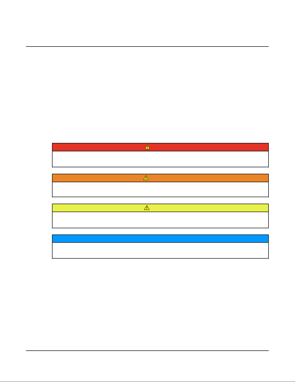
The following safety styles and symbols found throughout this manual indicate
potentially hazardous conditions to the operator, service personnel, or equipment.
DANGER
Indicates a hazardous situation that, if not avoided, will result in death or
serious injury.
WARNING
Indicates a hazardous situation that, if not avoided, could result in death or
serious injury.
CAUTION
Indicates a hazardous situation that, if not avoided, could result in minor or
moderate injury.
NOTICE
Indicates information considered important, but not hazard-related (e.g.,
messages relating to property damage).
1.2 Save These Instructions
This manual contains important instructions for the generator set that should be
followed during installation, operation and maintenance of the generator set and
batteries.
Thoroughly read the operator manual before operating the generator set. Safe
operation and top performance can only be obtained when equipment is properly
operated and maintained.
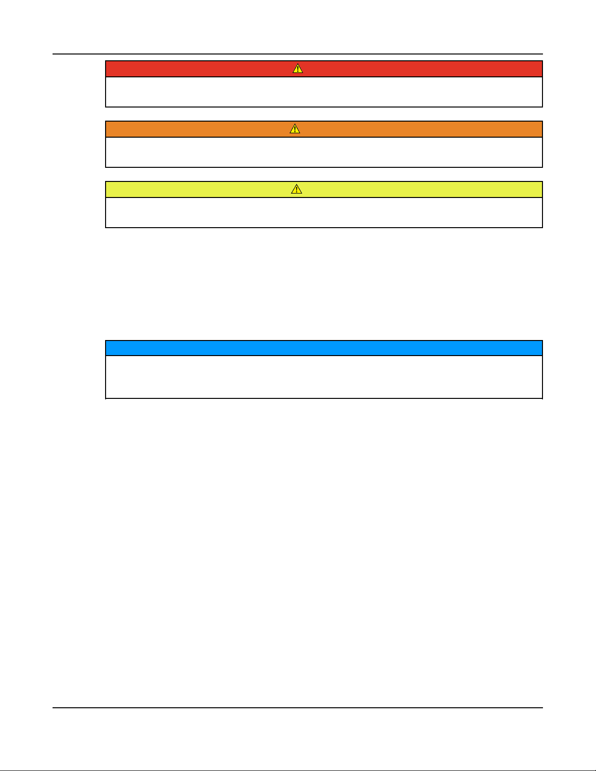
The following symbols in this manual alert you to potential hazards to the operator,
service person and equipment.
1A056K396 (Issue 2) Copyright © 2017 Cummins Inc.
1. IMPORTANT SAFETY INSTRUCTIONS 6-2017
DANGER
Alerts you to an immediate hazard that will result in severe personal injury or
death.
WARNING
Alerts you to a hazard or unsafe practice that can result in severe personal
injury or death.
CAUTION
Alerts you to a hazard or unsafe practice that can result in personal injury or
equipment damage.
1.3 General Information
This manual should form part of the documentation package supplied by Cummins
Inc. with specific generator sets. If this manual has been supplied in isolation,
please contact your authorized dealer.
It is in the operator's interest to read and understand all warnings and
cautions contained in the documentation relevant to the generator set
operation and daily maintenance.
1.4 General Precautions
• Keep multi-type ABC fire extinguishers accessible.
• Make sure that all fasteners are secure and torqued properly.
• Keep the generator set and its compartment clean. Do not store any items in
the generator set compartment.
• Before working on the generator set, make sure the generator set is shut down
and disabled.
1. Press the generator set's "O" (Off) button or the red STOP button on the
local display (whichever is applicable) to stop the generator set. Allow the
generator set to thoroughly cool to the touch.
2. If applicable, turn off and disconnect the battery charger from the AC
source before disconnecting the battery cables.
NOTICE
3. Disconnect the negative (–) cable from the battery and secure it from
contacting the battery terminals to prevent accidental starting.
2 A056K396 (Issue 2)Copyright © 2017 Cummins Inc.

1. IMPORTANT SAFETY INSTRUCTIONS6-2017
• Use caution when making adjustments when the generator set is running, hot,
or when parts are electrically live, as all situations may cause personal injury or
death.
• Used engine oil has been identified by some state and federal agencies as
causing cancer or reproductive toxicity. Do not ingest, inhale, or come into
contact with used oil or its vapors.
• Do not work on the generator set when mentally or physically fatigued or after
consuming alcohol or drugs.
NOTICE
Only trained and authorized personnel shall maintain or service the
generator set.
NOTICE
The installation of the generator set shall provide enough ventilation to
ensure that gases generated by vented batteries during charging, or caused
by equipment malfunction, are removed.
General Safety Precautions
WARNING
Hot Pressurized Liquid
Contact with hot liquid can cause severe burns.
Do not open the pressure cap while the engine is running. Let the engine
cool down before removing the cap. Turn the cap slowly and do not open it
fully until the pressure has been relieved.
WARNING
Moving Parts
Moving parts can cause severe personal injury.
Use extreme caution around moving parts. All guards must be properly
fastened to prevent unintended contact.
WARNING
Toxic Hazard
Used engine oils have been identified by some state and federal agencies to
cause cancer or reproductive toxicity.
Do not ingest, breathe the fumes, or contact used oil when checking or
changing engine oil. Wear protective gloves and face guard.
3A056K396 (Issue 2) Copyright © 2017 Cummins Inc.

1. IMPORTANT SAFETY INSTRUCTIONS 6-2017
WARNING
Electrical Generating Equipment
Incorrect operation and maintenance can result in severe personal injury or
death.
Do not operate equipment when fatigued, or after consuming any alcohol or
drug.
Make sure that only suitably trained and experienced service personnel
perform electrical and/or mechanical service.
WARNING
Toxic Gases
Substances in exhaust gases have been identified by some state and federal
agencies to cause cancer or reproductive toxicity.
Do not breathe in or come into contact with exhaust gases.
WARNING
High Noise Level
Generator sets in operation emit noise, which can cause hearing damage.
Wear appropriate ear protection at all times.
WARNING
Hot Surfaces
Contact with hot surfaces can cause severe burns.
The unit is to be installed so that the risk of hot surface contact by people is
minimized. Wear appropriate PPE when working on hot equipment and avoid
contact with hot surfaces.
WARNING
Toxic Hazard
Ethylene glycol, used as an engine coolant, is toxic to humans and animals.
Wear appropriate PPE. Clean up coolant spills and dispose of used coolant
in accordance with local environmental regulations.
WARNING
Combustible Liquid
Ignition of combustible liquids is a fire or explosion hazard which can cause
severe burns or death.
Do not store fuel, cleaners, oil, etc., near the generator set. Do not use
combustible liquids like ether.
4 A056K396 (Issue 2)Copyright © 2017 Cummins Inc.

1. IMPORTANT SAFETY INSTRUCTIONS6-2017
WARNING
Combustible Gases
Generator sets in operation have combustible gases under pressure, which
if ignited can cause eye and ear damage.
Wear appropriate eye and ear protection at all times.
WARNING
Combustible Gases
Generator sets in operation have combustible gases under pressure, which
if ignited can cause severe injury.
Do not operate the generator set with any doors open.
WARNING
Fire Hazard
Materials drawn into the generator set, as well as accumulated grease and
oil, are a fire hazard. Fire can cause severe burns or death.
Keep the generator set and the surrounding area clean and free from
obstructions. Make sure the generator set is mounted in a manner to prevent
combustible materials from accumulating under the unit.
WARNING
Automated Machinery
Accidental or remote starting of the generator set can cause severe personal
injury or death.
Isolate all auxiliary supplies and use an insulated wrench to disconnect the
starting battery cables (negative [–] first).
NOTICE
Keep multi-type ABC fire extinguishers close by. Class A fires involve
ordinary combustible materials such as wood and cloth. Class B fires
involve combustible and flammable liquid fuels and gaseous fuels. Class C
fires involve live electrical equipment. (Refer to NFPA No. 10 in the
applicable region.)
NOTICE
Before performing maintenance and service procedures on enclosed
generator sets, make sure the service access doors are secured open.
NOTICE
Stepping on the generator set can cause parts to bend or break, leading to
electrical shorts, or to fuel, coolant, or exhaust leaks. Do not step on the
generator set when entering or leaving the generator set room.
5A056K396 (Issue 2) Copyright © 2017 Cummins Inc.

1. IMPORTANT SAFETY INSTRUCTIONS 6-2017
1.5 Generator Set Voltage Is Deadly
• Generator set output connections must be made by a trained and experienced
electrician in accordance with all applicable codes.
• This generator set and the public utility may only be connected to house circuits
by means of the automatic transfer switch.
CAUTION
Improper connections can lead to electrocution of utility workers and
damage to equipment. Make sure that the connections are installed
properly by a trained technician.
• Use caution when working on live electrical equipment. Remove jewelry, and
make sure clothing and shoes are dry. Stand on a dry wooden platform.
1.6 Fuel and Fumes Are Flammable
Fire, explosion, and personal injury or death can result from improper practices.
• DO NOT permit any flame, cigarette, pilot light, spark, arcing equipment, or
other ignition source near the generator set or fuel system.
• Fuel lines must be adequately secured and free of leaks. Fuel connection at the
engine should be made with an approved flexible line. Do not use copper piping
on flexible lines because copper will become brittle if continuously vibrated or
repeatedly bent.
• Be sure all fuel supplies have a positive shutoff valve.
• Be sure the battery area has been well-ventilated prior to servicing near it.
Lead-acid batteries emit a highly explosive hydrogen gas that can be ignited by
arcing, sparking, smoking, etc.
6 A056K396 (Issue 2)Copyright © 2017 Cummins Inc.

1.7 Starting Batteries
Toxic Hazard
The electrolyte in starting batteries is a dilute sulfuric acid that is harmful to
the skin and eyes. It is also electrically conductive and corrosive.
Always:
1. Wear full eye protection and protective clothing;
2. If the electrolyte contacts the skin, wash it off immediately with water;
3. If the electrolyte contacts the eyes, flush them thoroughly and
immediately with water and seek medical attention; and
4. Wash spilled electrolyte down with an acid neutralizing agent. A
common practice is to use a solution of one pound (500 grams)
bicarbonate of soda (also known as baking soda or sodium bicarbonate)
to one gallon (4 liters) of water.
5. Continue to add the bicarbonate of soda solution until the evidence of
reaction (that is, foaming) has stopped.
6. Flush the resulting liquid with water and dry the area.
1. IMPORTANT SAFETY INSTRUCTIONS6-2017
WARNING
1.8 Batteries Can Explode
Batteries can explode, causing severe skin and eye burns and can release toxic
electrolytes.
Combustible Gases
Batteries can explode, causing severe skin and eye burns, and can release
toxic electrolytes.
Do not dispose of the battery in a fire, because it is capable of exploding. Do
not open or mutilate the battery. Do not charge frozen batteries.
Electric Shock Hazard
Batteries present the risk of high short circuit current.
When servicing the generator set:
• Remove watches, rings, or other metal objects.
• Use tools with insulated handles.
WARNING
WARNING
7A056K396 (Issue 2) Copyright © 2017 Cummins Inc.

1. IMPORTANT SAFETY INSTRUCTIONS 6-2017
NOTICE
Servicing of batteries must be performed or supervised by personnel
knowledgeable of batteries and the required precautions. Keep unauthorized
personnel away from batteries.
• Wear safety glasses.
• Do not smoke.
• Do not charge frozen batteries.
• To prevent arcing when disconnecting the battery:
1. Press the Off switch from the display and then press the E-Stop button.
2. Disconnect AC power from any battery chargers.
3. Remove the negative (-) battery cable to prevent starting.
• To prevent arcing when reconnecting the battery:
1. Reconnect the positive (+) cable.
2. Reconnect the negative (-) cable.
3. Reconnect the battery charger to AC power supply.
• When replacing the generator set battery, always replace it with a battery as
specified in this manual.
1.9 Vented Batteries
Toxic Hazard
The electrolyte in vented batteries is a dilute sulfuric acid that is harmful to
the skin and eyes. It is also electrically conductive and corrosive.
Always:
1. Wear full eye protection and protective clothing;
2. If the electrolyte contacts the skin, wash it off immediately with water;
3. If the electrolyte contacts the eyes, flush them thoroughly and
immediately with water and seek medical attention; and
4. Wash spilled electrolyte down with an acid neutralizing agent. A
common practice is to use a solution of one pound (500 grams)
bicarbonate of soda (also known as baking soda or sodium bicarbonate)
to one gallon (4 liters) of water.
5. Continue to add the bicarbonate of soda solution until the evidence of
reaction (that is, foaming) has stopped.
6. Flush the resulting liquid with water and dry the area.
WARNING
8 A056K396 (Issue 2)Copyright © 2017 Cummins Inc.

1. IMPORTANT SAFETY INSTRUCTIONS6-2017
1.10 Moving Parts Can Cause Severe Personal Injury or Death
• Do not wear loose clothing or jewelry near moving parts, such as cooling fans.
• Keep hands away from moving parts.
• Keep guards in place over fans.
1.11 Exhaust Gases Are Deadly
• Provide an adequate exhaust system to properly expel discharged gases away
from enclosed or sheltered areas, and areas where individuals are likely to
congregate. Visually and audibly inspect the exhaust system daily for leaks per
the maintenance schedule. Make sure that exhaust manifolds are secured and
not warped. Do not use exhaust gases to heat a compartment.
• Make sure the unit is well ventilated.
Exhaust Precautions
WARNING
Hot Exhaust Gases
Contact with hot exhaust gases can cause severe burns.
Wear personal protective equipment when working on equipment.
WARNING
Hot Surfaces
Contact with hot surfaces can cause severe burns.
The unit is to be installed so that the risk of hot surface contact by people is
minimized. Wear appropriate PPE when working on hot equipment and avoid
contact with hot surfaces.
WARNING
Toxic Gases
Inhalation of exhaust gases can cause asphyxiation and death.
Pipe exhaust gas outside and away from windows, doors, or other inlets to
buildings. Do not allow exhaust gas to accumulate in habitable areas.
WARNING
Fire Hazard
Contaminated insulation is a fire hazard. Fire can cause severe burns or
death.
Remove any contaminated insulation and dispose of it in accordance with
local regulations.
9A056K396 (Issue 2) Copyright © 2017 Cummins Inc.

1. IMPORTANT SAFETY INSTRUCTIONS 6-2017
The exhaust outlet may be sited at the top or bottom of the generator set. Make
sure that the exhaust outlet is not obstructed. Personnel using this equipment must
be made aware of the exhaust position. Position the exhaust away from flammable
materials - in the case of exhaust outlets at the bottom, make sure that vegetation is
removed from the vicinity of the exhaust.
The exhaust pipes may have some insulating covers fitted. If these covers become
contaminated they must be replaced before the generator set is run.
To minimize the risk of fire, make sure the following steps are observed:
• Make sure that the engine is allowed to cool thoroughly before performing
maintenance or operation tasks.
• Clean the exhaust pipe thoroughly.
1.12 The Hazards of Carbon Monoxide
Carbon monoxide (CO) is an odorless, colorless, tasteless and non-irritating gas.
You cannot see it or smell it. Red blood cells, however, have a greater affinity for
CO than for oxygen. Therefore, exposure even to low levels of CO for a prolonged
period can lead to asphyxiation (lack of oxygen) resulting in death. Mild effects of
CO poisoning include eye irritation, dizziness, headaches, fatigue and the inability to
think clearly. More extreme symptoms include vomiting, seizures and collapse.
Engine-driven generator sets produce harmful levels of carbon monoxide that can
injure or kill you.
Special Risks of CO near the Home
WARNING
Toxic Gases
Carbon monoxide (CO) gas can cause nausea, fainting, or death. Residents
can be exposed to lethal levels of CO when the generator set is running.
Depending on air temperature and wind, CO can accumulate in or near the
home.
To protect yourself and others from the dangers of CO poisoning, it is
recommended that reliable, approved, and operable CO detector alarms are
installed in proper locations in the home as specified by their manufacturer.
Protecting Yourself from CO Poisoning
• Locate the generator set in an area where there are no windows, doors, or
other access points into the home.
• Make sure all CO detectors are installed and working properly.
• Pay attention for signs of CO poisoning.
• Check the exhaust system for corrosion, obstruction, and leaks every time you
start the generator set and every eight hours when you run it continuously.
10 A056K396 (Issue 2)Copyright © 2017 Cummins Inc.

2 Introduction
2.1 About This Manual
Improper installation can result in severe personal injury, death and damage
to equipment. The installation must comply with all applicable building
codes (including project permits and inspections). The installer should be
properly trained and licensed to perform electrical and mechanical
equipment installations (including gaseous fuel installation).
Manuals are updated from time to time to reflect changes in the equipment
and its specifications. The most up-to-date version of this manual is found
on the QuickServe website
(https://quickserve.cummins.com/info/index.html).
This manual is a guide for the installation of the generator set models listed on the
front cover. Proper installation is essential for top performance, reliable operation,
and safety. Read through this manual before starting the installation. This manual
covers outdoor applications only; for other installations, refer to the T-030: Liquid-
Cooled Generator Set Application manual available from your Cummins distributor.
WARNING
NOTICE
NOTICE
The installation must comply with all applicable building codes.
See the generator set's specific operator manual for operation and maintenance and
specific service manual for service.
Refer to the Model Specifications section for specific information about the system
and its components.
Refer to the Outline and System Drawings appendix and the Wiring Diagrams
appendix for specific information about installation and wiring connections.
2.2 Schedule of Abbreviations
This list is not exhaustive. For example, it does not identify units of measure or
acronyms that appear only in parameters, event/fault names, or part/accessory
names.
11A056K396 (Issue 2) Copyright © 2017 Cummins Inc.

2. Introduction 6-2017
Abbr. Description Abbr. Description
AC Alternating Current LED Light-Emitting Diode
AMP AMP, Inc. (part of Tyco
MFM Multifunction Monitor
Electronics)
ANSI American National
Mil Std Military Standard
Standards Institute
ASOV Automatic Shut Off Valve MPU Magnetic Pickup
ASTM American Society for
NC Normally Closed
Testing and Materials
(ASTM International)
ATS Automatic Transfer
NC Not Connected
Switch
AVR Automatic Voltage
Regulator
NFPA National Fire Protection
Agency
AWG American Wire Gauge NO Normally Open
CAN Controlled Area Network NWF Network Failure
CB Circuit Breaker OEM Original Equipment
Manufacturer
CE Conformité Européenne OOR Out Of Range
CCA Cold Cranking Ampere OORH/
Out Of Range High
ORH
CFM Cubic Feet per Minute OORL/ORL Out Of Range Low
CGT Cummins Generator
PB Push Button
Technologies
CMM Cubic Meters per Minute PCC PowerCommand®Control
CT Current Transformer PGI Power Generation
Interface
DC Direct Current PGN Parameter Group
Number
DEF Diesel Exhaust Fluid PI Proportional/Integral
DPF Diesel Particulate Filter PID Proportional/Integral/
Derivative
EBS Excitation Boost System PLC Programmable Logic
Controller
ECM Engine Control Module PMG Permanent Magnet
Generator
12 A056K396 (Issue 2)Copyright © 2017 Cummins Inc.

2. Introduction6-2017
Abbr. Description Abbr. Description
ECS Engine Control System PPE Personal Protective
Equipment
EMI Electromagnetic
Interference
EN European Standard PTC Power Transfer Control
EPS Engine Protection
System
E-Stop Emergency Stop RFI Radio Frequency
FAE Full Authority Electronic RH Relative Humidity
FMI Failure Mode Identifier RMS Remote Monitoring
FSO Fuel Shutoff RMS Root Mean Square
Genset Generator Set RTU Remote Terminal Unit
GCP Generator Control Panel SAE Society of Automotive
GND Ground scfh Standard Cubic Feet of
HMI Human-Machine
Interface
PT Potential Transformer
PWM Pulse-Width Modulation
Interference
System
Engineers
gas per Hour
SCR Selective Catalytic
Reduction
IC Integrated Circuit SPN Suspect Parameter
ISO International Organization
for Standardization
LBNG Lean-Burn Natural Gas UL Underwriters
LCD Liquid Crystal Display UPS Uninterruptible Power
LCT Low Coolant
Temperature
2.3 Related Literature
Before any attempt is made to operate the generator set, the operator should take
time to read all of the manuals supplied with the generator set and familiarize
themselves with the warnings and operating procedures.
Number
SW_B+ Switched B+
Laboratories
Supply
13A056K396 (Issue 2) Copyright © 2017 Cummins Inc.

2. Introduction 6-2017
A generator set must be operated and maintained properly if you are to expect safe
and reliable operation. The Operator manual includes a maintenance schedule and
a troubleshooting guide. The Health and Safety manual must be read in conjunction
with the Operator manual for the safe operation of the generator set.
The following documents are shipped with the generator set:
• Installation Manual for QSJ8.9G Engine with PowerCommand 2.3 Control
(A056K396)
• Operator Manual for QSJ8.9G Engine with PowerCommand 2.3 Control
(A056K398)
• Health and Safety Manual (0908-0110-00)
• Global Commercial Warranty Statement (A040H442)
• Emission Warranty Statement (Federal Emissions EPA Title 40 CFR Part 90
Component Warranty) (A028X279)
The relevant manuals appropriate to your generator set are also available; the
documents below are in English:
• Generator Set Service Manual for QSJ8.9G Engine with PowerCommand 2.3
Control (A056K400)
• Controller Service Manual for PowerCommand 2.3 Controller (A030F082 [09000666])
• Recommended Spares List (RSL) for each model:
◦ C125 N6 (A057P648)
◦ C150 N6 (A057P650)
• Parts Manual for QSJ8.9G Engine with PowerCommand 2.3 Control
(A056K402)
• Universal Annunciator Owner Manual (0900-0301)
• Standard Repair Times - IB Family (A057P652)
• Service Tool Manual (A043D529)
• Failure Code Manual (F1115C)
• Engineering Application Manual T-030: Liquid Cooled Generator Sets
(A040S369)
2.4 Model Specifications
Damage caused by failure to follow the manufacturer's recommendation will
not be covered by the warranty. Please contact your authorized distributor.
NOTICE
14 A056K396 (Issue 2)Copyright © 2017 Cummins Inc.
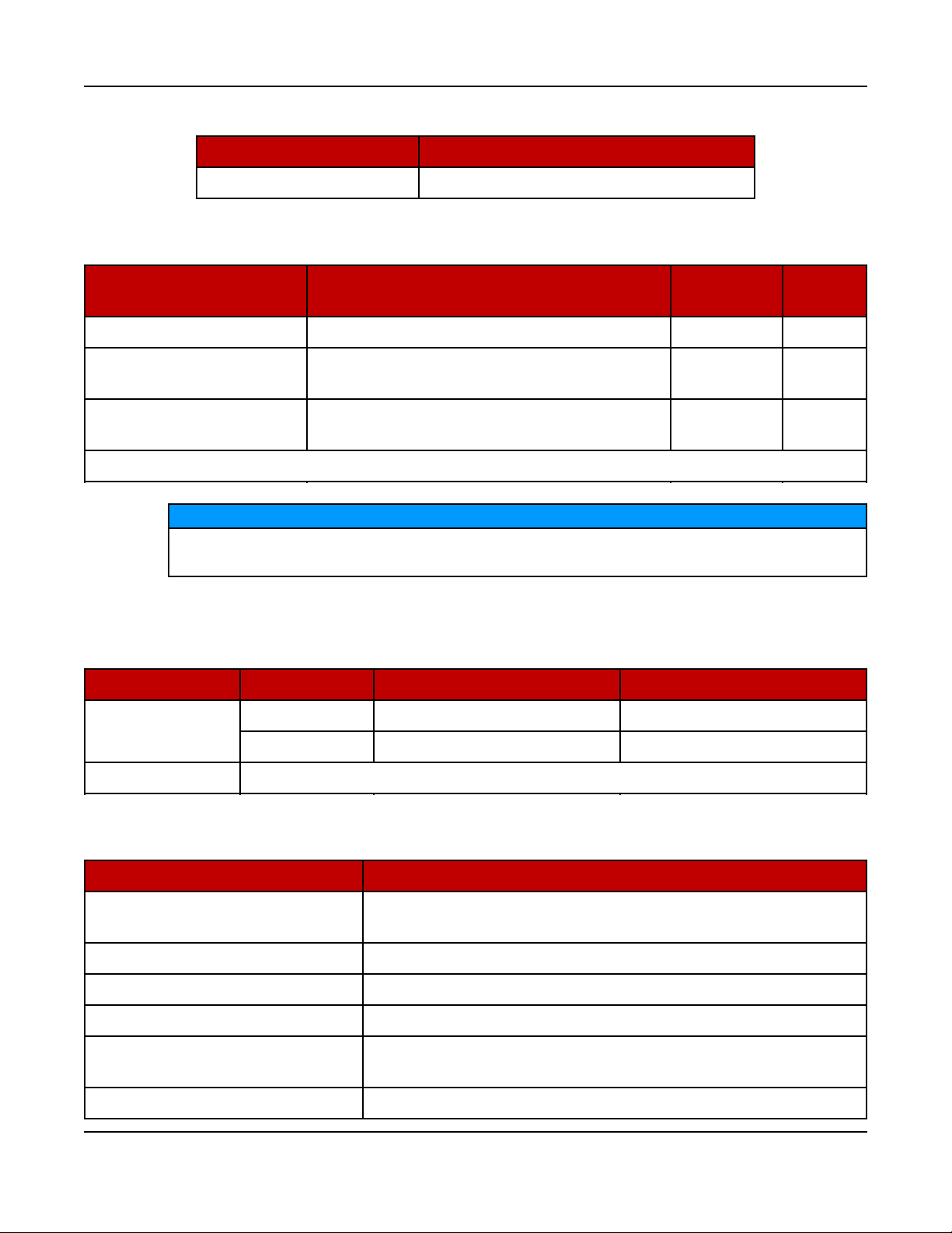
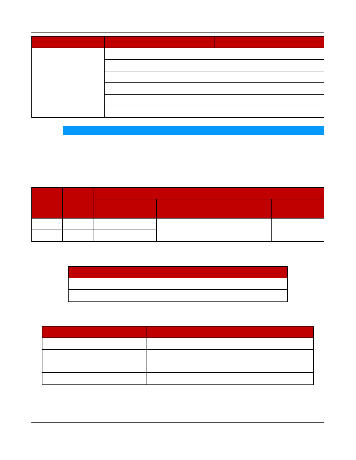
TABLE 1. 8.9L MODEL VARIATIONS
Models Description
C125 N6, C150 N6 60 Hz, 1800 RPM
TABLE 2. COLD WEATHER SPECIFICATIONS (ALL MODELS)
2. Introduction6-2017
Temperature Description of Components
Battery
Quantity
Group
Above 4 °C (40 °F) Battery charger 1 34
–17 - 4 °C (0 to 40 °F)
Below –17 °C (0 °F)
Battery charger, coolant heater (1500 W),
CCV heater*
Battery charger, coolant heater (2000 W),
oil heater, battery heater, CCV heater*
1 34
2 34
*CCV heaters are provided as part of the cold and extreme cold coolant heater packages.
NOTICE
For NFPA 110 applications, a coolant heater is required. A factory option is
available.
TABLE 3. FUEL SPECIFICATIONS 60 HZ, 1800 RPM
Type Unit C125 N6 C150 N6
Natural Gas
Full Load
scfh 1655 1893.3
BTU/hr 1,580,079 1,807,610
Fuel Pressure 1.5 - 3.2 kPa (6 to 13 inches of water column) under any condition
TABLE 4. ENGINE SPECIFICATIONS (ALL MODELS)
Type Specification
Engine
6 cylinder in-line, single-cam, liquid-cooled, 4-stroke, spark
ignited
Bore 114 mm (4.49 in)
Stroke 145 mm (5.69 in)
Displacement 8.9 L (543.1 in3)
Compression Ratio (Natural
Gas)
9.7:1
Firing Order 1-5-3-6-2-4
15A056K396 (Issue 2) Copyright © 2017 Cummins Inc.

2. Introduction 6-2017
Type Specification
Spark Plug Gap 0.40 mm (.016 in)
Spark Plug Torque 38 Nm (28 ft-lb)
Crankshaft Rotation (Viewed
from the Front of the Engine)
Engine Weight (Dry, Long Block
Only)
Clockwise
693 kg (1527.8 lb)
Valve Clearance (Intake) 0.355 mm (0.014 in)
Valve Clearance (Exhaust) 0.6604 mm (0.026 in)
• 50/50 coolant solution (50% pure water and 50% anti-
Coolant
freeze)
• 11 L (2.9 gal) capacity
Oil Capacity 22 L (5.81 gal)
• Must adhere to Cummins®Engineering Standard
(CES) 20085
• Use of improper oils can result in engine damage. Use
only the required oils:
◦ 5W-40 (all ambient temperatures)
◦ 15W-40 (above 4 °C [40 °F] ambient temperature)
Oil Standards
(use of GEO 15W-40 oil in ambient temperatures
below 4 °C (40 °F] could result in engine
turbocharger damage)
• A sulfated ash limit of 0.6% mass has been placed on
all engine lubricating oils recommended for use in
Cummins® B, natural gas engines. Higher ash oils can
cause valve and/or piston damage, cause spark plug
fouling, and lead to excessive oil consumption and
degradation of the catalyst.
TABLE 5. LUBRICATING OIL SYSTEM SPECIFICATIONS
Type Specification
Lubricating Oil Pressure at Idle (Minimum) 69 kPa (10 psi)
Lubricating Oil Pressure at Rated Speed (Minimum) 138 kPa (20 psi)
Filter Bypass Valve-Opening Pressure 345 kPa (50 psi)
Pressure Regulator Valve-Opening Pressure 417 kPa (60 psi)
Lubricating Oil Capacity (Standard Sump):
--High 19 L (20 qt)
16 A056K396 (Issue 2)Copyright © 2017 Cummins Inc.

2. Introduction6-2017
Type Specification
--Low 15 L (16 qt)
--Total System 20.8 L (22 qt)
TABLE 6. GENERATOR SET SIZE SPECIFICATIONS
Enclosure
Type
Open/Weather
2867 x 1016 x 1666 mm (113 x 40 x 65.6 in); does not include exhaust
Size (L x W x H)
discharge elbow
Sound Level 1 3621 x 1016 x 1666 mm (143 x 40 x 65.6 in)
Sound Level 2 4061 x 1016 x 1666 mm (160 x 40 x 65.6 in)
TABLE 7. GENERATOR SET WET WEIGHT (ALL MODELS) (60 HZ, 1800 RPM)
Configuration lbs kg
Open 3475 1576
Weather 3801 1724
Sound Level 1 3907 1772
Sound Level 2 3940 1787
NOTICE
Weights are approximate and can be affected by selected options. Refer to
outline drawings for specific weight information.
TABLE 8. ALTERNATOR SPECIFICATIONS 60 HZ, 1800 RPM
Type C125 N6 C150 N6
Generator Brushless, 4-pole rotating field, single bearing
Power (kVA) 1 Phase 125 150
Power (kVA) 3 Phase 156.25 187.5
17A056K396 (Issue 2) Copyright © 2017 Cummins Inc.
2. Introduction 6-2017
Type C125 N6 C150 N6
120/240, 1 Ph (Reconnectable)
227/480, 3 Ph WYE
347/600, 3 Ph WYE
Rated Voltages (V)
120/240, 3 Ph DELTA
120/208, 3 Ph WYE
127/220, 3 Ph WYE
NOTICE
Maximum I2= 8%. Generator set load unbalance must not exceed 25%
between any phases.
TABLE 9. GENERATOR SET DERATING GUIDELINES
Engine Power Available Up To... Derate At…
Model Phase
Elevation
Ambient
Temperature
C125 N6 1 & 3 2010 m (6600 ft)
40 °C (104 °F)
C150 N6 1 & 3 885 m (2900 ft)
TABLE 10. CONTROL SPECIFICATIONS (ALL MODELS)
Control Purpose
PowerCommand 2.3 Generator Set
Enovation 4G LDI Engine (125, 150 kW Generator Sets)
TABLE 11. DC SYSTEM SPECIFICATIONS (ALL MODELS)
Type Specification
Nominal Battery Voltage 12 VDC
Battery Group 34 (1 standard; 2 optional)
Elevation Temperature
4.5% per
300 m (985 ft)
1.5% per
10 °C (18 °F)
Battery Type Lead acid, maintenance-free
Minimum Cold Crank Amps 850 standard, 1080 high capacity
18 A056K396 (Issue 2)Copyright © 2017 Cummins Inc.
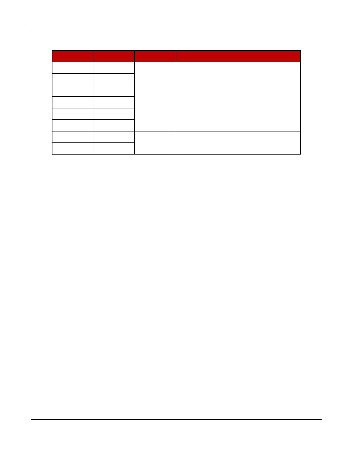
TABLE 12. FUSE SPECIFICATIONS
Fuse Amps Volts Comment
F1 20
F2 10
2. Introduction6-2017
F3 20
32
F4 5
F5 20
F6 10
F7 10
600 Class G size-rejecting, current limiting
F8 10
2.5 Before Installation
Before beginning the installation of the generator set, verify that the unit was
correctly selected. Check the following features:
• Model
• Specifications
• Options
• Fuel Supply
◦ The gas supplied to the generator set must be of acceptable quality.
¼” x 1¼” cylindrical glass cartridge,
fast acting
◦ The gas supply must have sufficient pressure. Care must be taken to be
sure that the gas supply at the generator set, not just at the source, is of
proper pressure for operation. The specified pressure must be available
while the generator set is starting and running at full load.
◦ The gas must be supplied to the generator set in sufficient volume to
support operation of the generator set. This is normally a matter of
selecting fuel line size to be large enough to transport the volume of fuel
needed.
19A056K396 (Issue 2) Copyright © 2017 Cummins Inc.

2. Introduction 6-2017
This page is intentionally blank.
20 A056K396 (Issue 2)Copyright © 2017 Cummins Inc.
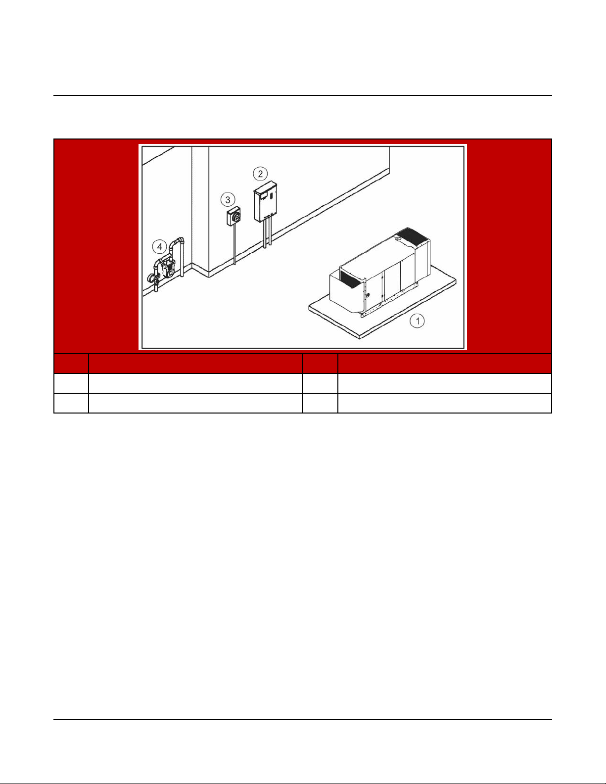
3 Pre-Installation Considerations
Areas of consideration:
No. Description No. Description
1 Generator Set 3 Electrical Meter
2 Transfer Switch 4 Natural Gas Meter
FIGURE 1. SITE PREPARATION EXAMPLE
• Location of the generator set - this is one of the first decisions to be made, as it
affects all other aspects of the installation, such as:
◦ Length of electric wiring
◦ Length of gas lines (natural gas line must be inspected by the gas utility
inspectors and building inspectors)
◦ Site preparation:
▪ Access to the site
▪ Trenches
▪ Site preparation materials needed
• Fuel supply pressure
• Automatic transfer switch location and connections
• Tools and materials required
• Accessories required (if any) for the customer's application (utility power may
be required at the generator set; make plans accordingly)
21A056K396 (Issue 2) Copyright © 2017 Cummins Inc.

3. Pre-Installation Considerations 6-2017
NOTICE
Depending on the locality and use of the generator set, it may be necessary
to obtain an air quality emissions permit before installation begins. Check
with local pollution control or air quality authority to determine permit
requirements.
3.2 Installation Codes and Standards for Safety
NOTICE
The generator set installer bears sole responsibility for following all
applicable local codes and regulations.
The following list of codes and standards may apply to the installation and operation
of the generator set. This list is for reference only and not intended to be inclusive of
all applicable codes and standards. The address of each agency is listed so that
copies of the codes may be obtained for reference. Installation codes and
recommendations are subject to change, and may vary by location or over time.
22 A056K396 (Issue 2)Copyright © 2017 Cummins Inc.

3. Pre-Installation Considerations6-2017
TABLE 13. INSTALLATION CODES AND STANDARDS FOR SAFETY
RECOMMENDATIONS
Type
US
Code or
Standard
Code
NFPA 70 - National Electrical
Code
Title Organization
NFPA 37 - Installation and Use
Code
of Stationary Combustion
Engines and Gas Turbines
Code
NFPA 54 - National Fuel Gas
Code
NFPA 58 - Storage and
Code
Handling of Liquefied Petroleum
Gases
NFPA 110 - Standard for
Code
Emergency and Standby Power
Systems
Code CSA Electrical Bulletin
Code
CSA 22.1 Canadian Electrical
Code
National Fire Protection
Association
470 Atlantic Avenue
Boston, MA 02210
Code
Canada
Standard
Standard
Code
Code
California Code
CSA B149 Installation Code for
Gas Burning Appliances and
Equipment
CSA C22.2 No. 100 Motors and
Generators
CSA C22.2 No. 14 Industrial
Control Equipment
CSA C282 Emergency Electrical
Power Supply for Buildings
CSA Z32 Electrical Safety in
Health Care Facilities
California Administrative Code Title 25 Chapter 3
Canadian Standards
Association
Housing and Construction
Materials Section
178 Rexdale Blvd.
Rexdale, Ontario, Canada M9Q
1R3
State of California
Documents Section
P.O. Box 1015
North Highlands, CA 95660
23A056K396 (Issue 2) Copyright © 2017 Cummins Inc.

3. Pre-Installation Considerations 6-2017
3.3 Required Items for Installation
Tools and materials are used for the installation of this generator set. These items
are identified in the following sections. Please refer to local codes and standards,
because they may affect the materials required.
Materials Required
NOTICE
Refer to local codes and standards, which may affect material requirements.
NOTICE
If a 100% rated breaker is used, 90 °C (194 °F) wire must be used with the
wire size determined by the 75 °C (167 °F) ampacity tables. Aluminum wire is
not allowed with 100% rated breakers.
NOTICE
If required, a UL-listed grounding electrode terminal within its ratings and
suitable for the application must be installed and labeled “Grounding
Electrode Terminal”.
Electrical Materials:
NOTICE
Class 1 wiring methods must be used for connecting the generator set.
• Use code compliant AC wiring for phase, neutral, and ground connections.
• Wire sizes (DC control and power and AC sense only):
◦ Control wires under 305 m (1000 feet) circuit length => 18-14 AWG of the
insulation type below
◦ Control wires 305 - 610 m (1000 - 2000 feet) circuit length => 16-14 AWG
of the insulation type below
• All control wires and cables must be rated 75 °C (167 °F) minimum, stranded
copper, and rated for wet locations.
◦ For wire sizes 14 AWG and larger, use insulation types: RHW, RHW-2,
THHW, THW, THW-2, THWN, THWN-2, XHHW, XHHW-2, USE-2, ZW-2
◦ For wire sizes 16 and 18 AWG, use insulation types: FFH-2, KFF-2, PAFF,
PFF, PGFF, PTFF, RFH-2, RFHH-2, RFHH-3, SFF-2, TFF, TFFN, ZFF
• Code compliant 20 A, 120 VAC, GFCI protected circuit for alternator heaters,
battery charger, coolant heater, oil heater, and/or battery heater (if equipped)
NOTICE
The optional high wattage coolant heater operates at 240 VAC.
24 A056K396 (Issue 2)Copyright © 2017 Cummins Inc.

3. Pre-Installation Considerations6-2017
• Code-compliant conduit for all wires
• Circuit breaker wire binding screws: 3/16”, 5/16”, ½”, 6 mm, 8 mm hex bit
• Customer connections to auxiliary I/O boards and relays
• Pozidriv screwdriver #2 and #3
NOTICE
Seismic zone installations require compliance to specific mounting
configurations.
Fuel Materials:
• Flexible fuel line (provided with the generator set, attached to the radiator
guard)
• UL listed pipe thread sealant
• Fuel line at generator set (natural gas fuel pressure: 1.5 - 3.2 kPa/6 - 13 inches
water column)
• Fuel pressure regulator (as required)
• Manual fuel shut-off at generator set ahead of automatic valves on generator
set fuel system
Tools Required
Use appropriate lifting techniques to position the generator set in place.
Loose Parts Shipped with the Generator Set
The following loose parts are shipped with the generator set:
• Flexible fuel hose assembly (attached to the radiator guard)
• One enclosure key (where applicable)
• Battery tie-down
• Sound level 2 baffle (where applicable)
• Weather enclosure exhaust elbow (where applicable)
• Literature (operator manual, installation manual, health and safety manual, and
warranty statements)
25A056K396 (Issue 2) Copyright © 2017 Cummins Inc.

3. Pre-Installation Considerations 6-2017
This page is intentionally blank.
26 A056K396 (Issue 2)Copyright © 2017 Cummins Inc.
 Loading...