

Page 1

OwnersOwners ManualManual
Generator Set
QSK60G and QSV91 Engines with PowerCommand
3.3 Control
C995 N5C
C1160 N5C
C1200 N5C
C1400 N5C
C1540 N5C
C1750 N5C
C2000 N5C
C1000 N6C
C1100 N6C
®
C1250 N6C
C1400 N6C
C1540 N6C
C1750 N6C
C2000 N6C
C1000 N6
C1250 N6
C1350 N6
C1700 N6
English
Original Instructions
3-2016 0908-0209 (Issue 6)
Page 2

Page 3

Table of Contents
1. IMPORTANT SAFETY INSTRUCTIONS.................................................................................. 1
1.1 Warning, Caution, and Note Styles Used in This Manual ................................................ 1
1.2 General Information........................................................................................................... 1
1.2.1 General Safety Precautions.................................................................................... 1
1.3 Generator Set Safety Code............................................................................................... 4
1.3.1 Moving Parts Can Cause Severe Personal Injury or Death................................... 4
1.3.2 Positioning of Generator Set - Open Sets .............................................................. 4
1.3.3 Moving the Generator Set ...................................................................................... 4
1.3.4 Alternator Operating Areas..................................................................................... 6
1.4 Electrical Shocks and Arc Flashes Can Cause Severe Personal Injury or Death ............ 6
1.4.1 AC Supply and Isolation ......................................................................................... 7
1.4.2 Medium Voltage Equipment (601 V to 15 kV - North America).............................. 7
1.5 Fuel and Fumes Are Flammable ....................................................................................... 7
1.5.1 Natural Gas ............................................................................................................ 7
1.5.2 Spillage.................................................................................................................. 8
1.5.3 Fluid Containment ................................................................................................. 8
1.5.4 Do Not Operate in Flammable and Explosive Environments ................................. 8
1.6 Exhaust Gases Are Deadly ............................................................................................... 8
1.6.1 Exhaust Precautions.............................................................................................. 9
1.7 Decommissioning and Disassembly.................................................................................. 9
2. INTRODUCTION .................................................................................................................... 11
2.1 About This Manual .......................................................................................................... 11
2.2 Schedule of Abbreviations............................................................................................... 11
2.3 Related Literature ............................................................................................................ 13
2.3.1 Further Information - Literature............................................................................. 13
2.4 After Sales Services ........................................................................................................ 14
2.4.1 Maintenance........................................................................................................ 14
2.4.2 Warranty ............................................................................................................... 14
2.4.3 How to Obtain Service ......................................................................................... 14
2.5 Project Details ................................................................................................................. 15
3. SYSTEM OVERVIEW............................................................................................................. 17
3.1 Generator Set Identification............................................................................................. 17
3.1.1 Generator Set Rating............................................................................................ 17
3.1.2 Nameplate - Open Generator Set ........................................................................ 17
3.2 Generator Set Components ............................................................................................ 17
3.3 Air Cleaner....................................................................................................................... 19
3.3.1 Air Cleaner System............................................................................................... 19
3.4 Coolant Specification....................................................................................................... 20
3.5 Gas Train......................................................................................................................... 21
3.6 Heaters ............................................................................................................................ 21
3.6.1 Heater Supply and Isolation ................................................................................. 21
3.7 Mains (Utility) Powered Battery Charger ......................................................................... 22
3.8 Oil Specification............................................................................................................... 22
3.8.1 Low BTU Gas Engines ......................................................................................... 23
i0908-0209 (Issue 6)
Copyright © 2016 Cummins Inc.
Page 4

Table of Contents 3-2016
3.9 Sensors ........................................................................................................................... 24
3.10 System Options ............................................................................................................. 24
3.10.1 PowerCommand Universal Annunciator............................................................. 24
3.10.2 Mains (Utility) Powered Battery Charger ............................................................ 25
3.10.3 Coolant Heater ................................................................................................... 26
4. CONTROL SYSTEM - POWERCOMMAND 3.3 .................................................................... 27
4.1 Control System Description............................................................................................. 27
4.1.1 Control System Panel........................................................................................... 27
4.1.2 Operating Modes .................................................................................................. 28
4.1.3 Power On and Sleep Modes ................................................................................ 30
4.2 Operator Panel ................................................................................................................ 30
4.2.1 Selection Buttons.................................................................................................. 31
4.2.2 Default Settings .................................................................................................... 32
4.2.3 Lamp Indicators .................................................................................................... 32
4.2.4 Lamp (LED) Test Button ...................................................................................... 32
4.2.5 Reset Button ........................................................................................................ 32
4.2.6 CB Open Button .................................................................................................. 32
4.2.7 CB Closed Button ................................................................................................ 33
4.2.8 Graphical Display and Buttons ............................................................................. 33
4.3 Operator Panel - Initial Operator Menu ........................................................................... 35
4.3.1 Initial Menu Data................................................................................................... 35
4.4 Operator Panel - Generator Set Data Operator Menu .................................................... 37
4.4.1 Generator Set Data .............................................................................................. 37
4.5 Operator Panel - Engine Data Operator Menu................................................................ 39
4.5.1 Engine Data.......................................................................................................... 39
4.5.2 History/About Menu .............................................................................................. 41
4.6 Operator Panel - Alternator Data Operator Menu ........................................................... 43
4.6.1 Alternator Data ..................................................................................................... 44
4.7 Operator Panel - Faults and Warnings Menus................................................................ 46
4.7.1 Fault Menu............................................................................................................ 46
4.7.2 Fault Messages .................................................................................................... 48
4.7.3 Fault Acknowledgement ....................................................................................... 48
4.7.4 Warning Fault Menu ............................................................................................. 48
4.7.5 Faults History Data Operator Menu...................................................................... 50
4.8 Operator Panel - Adjust Menu......................................................................................... 52
4.9 Operator Panel - Genset Setup Data Operator Menu..................................................... 53
4.10 Operator Panel - Paralleling Status Menu..................................................................... 54
4.11 Operator Panel - Paralleling/Basic Setup Menu............................................................ 61
4.12 Selecting Operating Modes ........................................................................................... 64
4.12.1 Passwords and Mode Change Access............................................................... 64
4.12.2 Selecting Manual Run Mode .............................................................................. 65
4.12.3 Selecting Auto Mode .......................................................................................... 66
4.12.4 Selecting Off Mode............................................................................................. 67
5. OPERATION - POWERCOMMAND 3.3................................................................................. 69
5.1 Safety .............................................................................................................................. 69
5.2 Introduction ...................................................................................................................... 69
5.3 Maintenance .................................................................................................................... 69
5.4 Operating Recommendations.......................................................................................... 70
Copyright © 2016 Cummins Inc.
ii 0908-0209 (Issue 6)
Page 5

Table of Contents3-2016
5.4.1 Running-in ............................................................................................................ 70
5.4.2 No Load Operation ............................................................................................... 70
5.4.3 Exercise Period .................................................................................................... 70
5.4.4 Low Operating Temperatures............................................................................... 70
5.4.5 High Operating Temperatures.............................................................................. 70
5.4.6 Operating Conditions............................................................................................ 70
5.4.7 De-Rating Factors ............................................................................................... 72
5.5 Generator Set Operation ................................................................................................. 72
5.5.1 Sequence of Operation......................................................................................... 72
5.6 Starting ............................................................................................................................ 73
5.6.1 Operator’s Pre-start Checks ................................................................................. 73
5.6.2 Starting at Operator Panel (Manual Run Mode)................................................... 74
5.6.3 Starting from Remote Location (Auto Mode)........................................................ 75
5.6.4 Cold Starting with Loads ...................................................................................... 76
5.7 Stopping .......................................................................................................................... 76
5.7.1 Stopping at Operator Panel (Manual Mode)......................................................... 77
5.7.2 Stopping from Operator Panel (Auto Mode) ......................................................... 77
5.7.3 Stopping from Remote Location (Auto Mode)...................................................... 77
5.7.4 Emergency Stop (Code 1433 or 1434) ............................................................... 78
5.8 Paralleling Operation ....................................................................................................... 79
5.8.1 Speed and Voltage Matching ............................................................................... 79
5.8.2 Operation When in Parallel ................................................................................. 79
5.8.3 Generator Set Application Type ........................................................................... 79
5.8.4 Standalone Application......................................................................................... 80
5.8.5 Synchronize Only ................................................................................................. 81
5.8.6 Isolated Bus Only ................................................................................................. 82
5.8.7 Power Transfer Control ........................................................................................ 83
5.8.8 Conditions for Each Paralleling State................................................................... 87
6. MAINTENANCE...................................................................................................................... 97
6.1 Locking the Generator Set Out of Service ...................................................................... 98
6.1.1 Immobilizing for Safe Working.............................................................................. 98
6.2 Periodic Maintenance ...................................................................................................... 99
6.2.1 Periodic Maintenance Schedule........................................................................... 99
6.3 Maintenance Procedures - Daily ................................................................................... 100
6.3.1 General Information............................................................................................ 101
6.3.2 Engine Operation Report................................................................................... 101
6.4 Air Intake System .......................................................................................................... 101
6.4.1 Air Cleaner Service Indicator.............................................................................. 102
6.4.2 Air Cleaner System............................................................................................. 102
6.4.3 Air Cleaner System............................................................................................. 103
6.4.4 Air Cleaner System............................................................................................. 103
6.4.5 Air Cleaner Element Replacement ..................................................................... 104
6.5 Batteries ........................................................................................................................ 105
6.5.1 Storage ............................................................................................................... 105
6.5.2 Safety Precautions ............................................................................................. 105
6.5.3 Battery Maintenance........................................................................................... 106
6.5.4 Electrolyte - Specific Gravity and Temperature.................................................. 108
6.5.5 Electrolyte Levels and Bench Charging Rates................................................... 110
6.5.6 Battery Fault Finding .......................................................................................... 112
iii0908-0209 (Issue 6)
Copyright © 2016 Cummins Inc.
Page 6

Table of Contents 3-2016
6.6 Cooling System ............................................................................................................. 113
6.6.1 Water Quality Check........................................................................................... 113
6.6.2 Radiator - Check................................................................................................. 113
6.6.3 Cooling Fan - Inspection .................................................................................... 114
6.7 DC Electrical System..................................................................................................... 114
6.8 Engine Oil ...................................................................................................................... 115
6.8.1 Oil Maintainer - Level Check and Fill ................................................................. 115
6.8.2 Crankcase Ventilation Re-circulator ................................................................... 116
6.9 Exhaust System............................................................................................................. 117
6.10 Fuel System................................................................................................................. 118
6.10.1 Fuel consumption ............................................................................................. 118
6.10.2 Methane Index.................................................................................................. 118
6.10.3 De-rate.............................................................................................................. 118
6.11 Gearbox Inspection ..................................................................................................... 119
6.12 Generator Set Output - AC Electric System ................................................................ 119
6.13 Hoses and Fuel Lines - Check .................................................................................... 120
6.14 Lubricating Oil Analysis ............................................................................................... 120
6.15 Storage and Lay-up of Generator Set ......................................................................... 121
7. TROUBLESHOOTING.......................................................................................................... 123
7.1 Control System .............................................................................................................. 123
7.2 Safety Considerations ................................................................................................... 123
7.3 Fault Finding.................................................................................................................. 124
7.4 Status Indicators - PowerCommand 3.3........................................................................ 125
7.4.1 Not in Auto ......................................................................................................... 125
7.4.2 Remote Start ..................................................................................................... 125
7.4.3 Warning ............................................................................................................. 125
7.4.4 Shutdown Status ............................................................................................... 125
7.4.5 Generator Set Running Lamp ........................................................................... 125
7.5 Fault/Status Codes - PowerCommand 3.3.................................................................... 125
7.5.1 Fault Messages .................................................................................................. 126
7.5.2 Fault Acknowledgement ..................................................................................... 126
7.5.3 Fault Codes - PowerCommand 3.3 .................................................................... 126
7.5.4 Troubleshooting Procedure for Fault Codes ...................................................... 161
7.6 Line Circuit Breaker....................................................................................................... 165
8. BATTERY CHARGER .......................................................................................................... 167
8.1 Mains (Utility) Powered Battery Charger - Wall-Mounted (24 VDC - 30 Amp) ............. 167
8.1.1 Boost................................................................................................................... 167
8.1.2 Specifications - 30 Amp...................................................................................... 168
8.2 Circuits........................................................................................................................... 168
9. MANUFACTURING FACILITIES .......................................................................................... 169
Copyright © 2016 Cummins Inc.
iv 0908-0209 (Issue 6)
Page 7

1 Important Safety Instructions
Save these instructions. This manual contains important instructions that should be followed during
installation and maintenance of the generator set.
Safe and efficient operation can be achieved only if the equipment is properly operated and
maintained. Many accidents are caused by failure to follow fundamental rules and precautions.
1.1 Warning, Caution, and Note Styles Used in This Manual
The following safety styles and symbols found throughout this manual indicate potentially hazardous
conditions to the operator, service personnel, or equipment.
DANGER
Indicates a hazardous situation that, if not avoided, will result in death or serious injury.
WARNING
Indicates a hazardous situation that, if not avoided, could result in death or serious injury.
CAUTION
Indicates a hazardous situation that, if not avoided, could result in minor or moderate injury.
NOTICE
Indicates information considered important, but not hazard-related (e.g., messages relating to
property damage).
1.2 General Information
This manual should form part of the documentation package supplied by Cummins Power Generation
with specific generator sets. In the event that this manual has been supplied in isolation please
contact your authorized distributor.
NOTICE
It is in the operator’s interest to read and understand all warnings and cautions contained
within the documentation relevant to the generator set, its operation and daily maintenance.
1.2.1 General Safety Precautions
WARNING
Hot Pressurized Liquid
Contact with hot liquid can cause severe burns.
Do not open the pressure cap while the engine is running. Let the engine cool down before
removing the cap. Turn the cap slowly and do not open it fully until the pressure has been
relieved.
10908-0209 (Issue 6)
Copyright © 2016 Cummins Inc.
Page 8
1. Important Safety Instructions 3-2016
WARNING
Moving Parts
Moving parts can cause severe personal injury.
Use extreme caution around moving parts. All guards must be properly fastened to prevent
unintended contact.
WARNING
Toxic Hazard
Used engine oils have been identified by some state and federal agencies to cause cancer or
reproductive toxicity.
Do not ingest, breathe the fumes, or contact used oil when checking or changing engine oil.
Wear protective gloves and face guard.
WARNING
Electrical Generating Equipment
Incorrect operation can cause severe personal injury or death.
Do not operate equipment when fatigued, or after consuming any alcohol or drug.
WARNING
Toxic Gases
Substances in exhaust gases have been identified by some state and federal agencies to
cause cancer or reproductive toxicity.
Do not breathe in or come into contact with exhaust gases.
WARNING
Combustible Liquid
Ignition of combustible liquids is a fire or explosion hazard which can cause severe burns or
death.
Do not store fuel, cleaners, oil, etc., near the generator set.
WARNING
High Noise Level
Generator sets in operation emit noise, which can cause hearing damage.
Wear appropriate ear protection at all times.
WARNING
Hot Surfaces
Contact with hot surfaces can cause severe burns.
Wear appropriate PPE when working on hot equipment and avoid contact with hot surfaces.
Electrical Generating Equipment
Incorrect operation and maintenance can result in severe personal injury or death
Make sure that only suitably trained and experienced service personnel perform electrical
and/or mechanical service.
Copyright © 2016 Cummins Inc.
WARNING
2 0908-0209 (Issue 6)
Page 9

1. Important Safety Instructions3-2016
WARNING
Toxic Hazard
Ethylene glycol, used as an engine coolant, is toxic to humans and animals.
Wear appropriate PPE. Clean up coolant spills and dispose of used coolant in accordance
with local environmental regulations.
WARNING
Combustible Liquid
Ignition of combustible liquids is a fire or explosion hazard which can cause severe burns or
death.
Do not use combustible liquids like ether.
WARNING
Automated Machinery
Accidental or remote starting of the generator set can cause severe personal injury or death.
Isolate all auxiliary supplies and use an insulated wrench to disconnect the starting battery
cables (negative [–] first).
WARNING
Fire Hazard
Materials drawn into the generator set are a fire hazard. Fire can cause severe burns or death.
Make sure the generator set is mounted in a manner to prevent combustible materials from
accumulating under the unit.
WARNING
Fire Hazard
Accumulated grease and oil are a fire hazard. Fire can cause severe burns or death.
Keep the generator set and the surrounding area clean and free from obstructions. Repair oil
leaks promptly.
WARNING
Fire Hazard
Materials drawn into the generator set are a fire hazard. Fire can cause severe burns or death.
Keep the generator set and the surrounding area clean and free from obstructions.
NOTICE
Keep multi-class ABC fire extinguishers handy. Class A fires involve ordinary combustible
materials such as wood and cloth. Class B fires involve combustible and flammable liquid
fuels and gaseous fuels. Class C fires involve live electrical equipment. (Refer to NFPA No. 10
in applicable region.)
NOTICE
Before performing maintenance and service procedures on enclosed generator sets, make
sure the service access doors are secured open.
30908-0209 (Issue 6)
Copyright © 2016 Cummins Inc.
Page 10

1. Important Safety Instructions 3-2016
NOTICE
Stepping on the generator set can cause parts to bend or break, leading to electrical shorts,
or to fuel, coolant, or exhaust leaks. Do not step on the generator set when entering or
leaving the generator set room.
1.3 Generator Set Safety Code
Before operating the generator set, read the manuals and become familiar with them and the
equipment. Safe and efficient operation can be achieved only if the equipment is properly operated
and maintained. Many accidents are caused by failure to follow fundamental rules and precautions.
WARNING
Electrical Generating Equipment
Incorrect operation and maintenance can result in severe personal injury or death.
Read and follow all Safety Precautions, Warnings, and Cautions throughout this manual and
the documentation supplied with the generator set.
1.3.1 Moving Parts Can Cause Severe Personal Injury or Death
• Keep hands, clothing, and jewelry away from moving parts.
• Before starting work on the generator set, disconnect the battery charger from its AC source,
then disconnect the starting batteries using an insulated wrench, negative (–) cable first. This will
prevent accidental starting.
• Make sure that fasteners on the generator set are secure. Tighten supports and clamps; keep
guards in position over fans, drive belts, etc.
• Do not wear loose clothing or jewelry in the vicinity of moving parts or while working on electrical
equipment. Loose clothing and jewelry can become caught in moving parts.
• If any adjustments must be made while the unit is running, use extreme caution around hot
manifolds, moving parts, etc.
1.3.2 Positioning of Generator Set - Open Sets
The area for positioning the set should be adequate and level, and the area immediately around the
set must be free of any flammable material.
1.3.3 Moving the Generator Set
WARNING
Heavy Load
Incorrect lifting or repositioning can cause severe personal injury or death.
Make sure that only suitably trained and experienced personnel transport and handle
generator sets and associated components.
Heavy Load
Incorrect lifting or repositioning can cause severe personal injury or death.
Do not lift the generator set by attaching to the engine or alternator lifting points. Do not
stand under or near the generator set when lifting.
Copyright © 2016 Cummins Inc.
WARNING
4 0908-0209 (Issue 6)
Page 11

1. Important Safety Instructions3-2016
WARNING
Mechanical Hazard
Failed components may be ejected or operate incorrectly which can cause severe personal
injury or death.
Do not climb the generator set; this may damage critical parts.
NOTICE
Access or service doors must be closed and locked before repositioning, and they must
remain locked during transportation and siting.
It is essential that there are sufficient trained and experienced personnel in attendance to make sure
the lifting and transportation of the generator set is undertaken in a safe and appropriate manner, and
in accordance to local guidelines and legislation.
Before lifting the generator set, lifting points, angle of slings, mass, access to intended site, and the
distance of movement should all be taken into account when organizing a suitable crane/hoist. Consult
the generator set information supplied with the generator set for details of dimensions and mass.
• Make sure that the crane operating area is able to support the mass of the crane and the
generator set.
• Make sure the equipment used for lifting is adequate to support the weight of the generator set.
• Attach the lifting device to the lifting points only using suitable shackles, chains, and spreader
bars.
• Slowly tighten the slings. Inspect the lifting attachments before commencing a full lift to make
sure they are attached correctly.
• Hoist the generator set slowly using the indicated lifting points only.
• Guide the generator set with ropes at a safe distance to prevent uncontrolled rotation when
positioning the generator set.
• Move the generator set to the desired location and place in position, bringing the set down
slowly.
• Loosen the slings; unhook and remove the shackles.
1.3.3.1 Positioning a Generator Set Using a Forklift Truck
WARNING
Heavy Load
Incorrect lifting or repositioning can cause severe personal injury or death.
Make sure that only suitably trained and experienced personnel transport and handle
generator sets and associated components.
WARNING
Heavy Load
Incorrect lifting or repositioning can cause severe personal injury or death.
Do not attempt to lift a generator set with an undersized forklift truck.
NOTICE
Access or service doors must be closed and locked before repositioning, and they must
remain locked during transportation and siting.
When using a forklift truck to transport/position the generator set, the dimensions, mass, and route
must be taken into account when selecting an appropriate lifting truck.
50908-0209 (Issue 6)
Copyright © 2016 Cummins Inc.
Page 12
1. Important Safety Instructions 3-2016
It is essential that there are sufficient trained and experienced personnel in attendance to make sure
the lifting and transportation of the generator set is undertaken in a safe and appropriate manner.
1. Insert the arms of the forklift into the forklift pockets. Make sure the generator set completely
rests on the forklift arms.
2. Lift and handle the equipment slowly.
3. Lower the generator set in position.
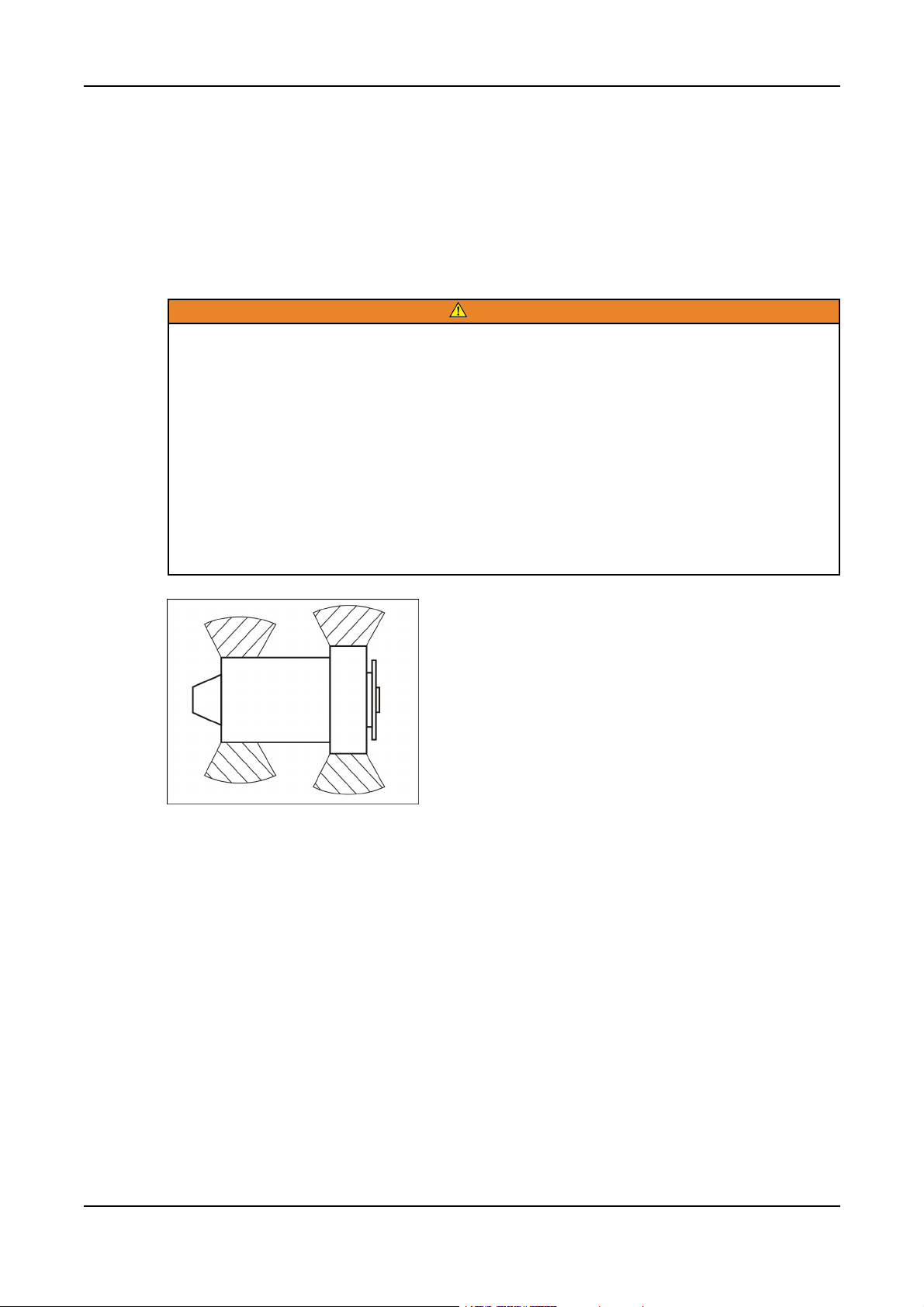
1.3.4 Alternator Operating Areas
WARNING
Ejected Debris
Debris ejected during catastrophic failure can cause serious injury or death by impact,
severing or stabbing.
To prevent injury:
• Keep away from the air inlet and air outlet when the alternator is running.
• Do not put operator controls near the air inlet and air outlet.
• Do not cause overheating by running the alternator outside rating plate parameters.
• Do not overload the alternator.
• Do not run an alternator with excessive vibration.
• Do not synchronize parallel alternators outside the specified parameters.
Always wear suitable PPE when working in the hatched areas shown in the diagram or directly in-line
with any air inlet/outlet.
Make sure this consideration is captured in your risk assessment.
1.4 Electrical Shocks and Arc Flashes Can Cause Severe Personal Injury or Death
• Only qualified service personnel certified and authorized to work on power circuits should work
on exposed energized power circuits.
• All relevant service material must be available for any electrical work performed by certified
service personnel.
• Exposure to energized power circuits with potentials of 50 VAC or 75 VDC or higher poses a
significant risk of electrical shock and electrical arc flash.
• Refer to standard NFPA 70E, or equivalent safety standards in corresponding regions, for details
of the dangers involved and for safety requirements.
Copyright © 2016 Cummins Inc.
6 0908-0209 (Issue 6)
Page 13

1. Important Safety Instructions3-2016
1.4.1 AC Supply and Isolation
NOTICE
Local electrical codes and regulations (for example, BS EN 12601:2010 Reciprocating internal
combustion engine driven generating sets) may require the installation of a disconnect
means for the generator set, either on the generator set or where the generator set
conductors enter a facility.
NOTICE
The AC supply must have the correct over current and earth fault protection according to
local electrical codes and regulations. This equipment must be earthed (grounded).
It is the sole responsibility of the customer to provide AC power conductors for connection to load
devices and the means to isolate the AC input to the terminal box; these must comply with local
electrical codes and regulations. Refer to the wiring diagram supplied with the generator set.
The disconnecting device is not provided as part of the generator set, and Cummins Power
Generation accepts no responsibility for providing the means of isolation.
1.4.2 Medium Voltage Equipment (601 V to 15 kV - North America)
• Medium voltage acts differently than low voltage. Special equipment and training is required to
work on or around medium voltage equipment. Operation and maintenance must be done only
by persons trained and experienced to work on such devices. Improper use or procedures will
result in severe personal injury or death.
• Do not work on energized equipment. Unauthorized personnel must not be permitted near
energized equipment. Due to the nature of medium voltage electrical equipment, induced voltage
remains even after the equipment is disconnected from the power source. Plan the time for
maintenance with authorized personnel so that the equipment can be de-energized and safely
grounded.
1.5 Fuel and Fumes Are Flammable
Fire, explosion, and personal injury or death can result from improper practices.
• Do not fill fuel tanks while the engine is running unless the tanks are outside the engine
compartment. Fuel contact with hot engine or exhaust is a potential fire hazard.
• Do not permit any flame, cigarette, pilot light, spark, arcing equipment, or other ignition source
near the generator set or fuel tank.
• Fuel lines must be adequately secured and free of leaks. Fuel connection at the engine should
be made with an approved flexible line. Do not use copper piping on flexible lines as copper will
become brittle if continuously vibrated or repeatedly bent.
• Make sure all fuel supplies have a positive shutoff valve.
• Make sure the battery area has been well-ventilated prior to servicing near it. Lead-acid batteries
emit a highly explosive hydrogen gas that can be ignited by arcing, sparking, smoking, etc.
1.5.1 Natural Gas
Pipeline Natural Gas is lighter than air. If leakage occurs the gas will first accumulate at high levels,
including ceiling voids. Gas detection equipment should be installed at high level to be effective. If
leakage occurs isolate the gas supply, do not operate any equipment (electrical or otherwise) that may
cause a spark or may be a source of ignition, evacuate the building and completely ventilate the area.
Only suitable qualified personnel who are adequately trained to manage natural gas emergencies are
to be allowed near the plant room or generator set(s) in such emergencies.
70908-0209 (Issue 6)
Copyright © 2016 Cummins Inc.
Page 14

1. Important Safety Instructions 3-2016
Non-Pipeline Gas Generator Sets are designated by Cummins, Inc. as Low Btu Generator Sets. NonPipeline Gas classification includes Landfill Gas, Digester Gas, Well Head Gas and Coal Bed
Methane. Non-pipeline gas, depending on its properties, can be lighter than air, neutral, or heavier
than air. If leakage occurs the gas can accumulate either at high level, mid-level or low level. Gas
detection equipment siting is dependant upon the properties of the gas.
Non-pipeline gases may also contain other substances which may be harmful and can cause personal
injury or death. Analysis of the non-pipeline gas available at site should be performed to identify the
gases properties and consistencies.
Shut down the generator set by following the shut down procedure as described in this manual. Fully
shut the gas train shut-off valve(s). Fully shut all external gas supply valves to the generator set. Alert
the emergency services and local gas supplier.
1.5.2 Spillage
Any spillage that occurs during fueling or during oil top-off or oil change must be cleaned up before
starting the generator set.
1.5.3 Fluid Containment
NOTICE
Where spillage containment is not part of a Cummins supply, it is the responsibility of the
installer to provide the necessary containment to prevent contamination of the environment,
especially water courses and sources.
If fluid containment is incorporated into the bedframe, it must be inspected at regular intervals. Any
liquid present should be drained out and disposed of in line with local health and safety regulations.
Failure to perform this action may result in spillage of liquids which could contaminate the surrounding
area.
Any other fluid containment area must also be checked and emptied, as described above.
1.5.4 Do Not Operate in Flammable and Explosive Environments
Flammable vapor can cause an engine to over speed and become difficult to stop, resulting in
possible fire, explosion, severe personal injury, and death. Do not operate a generator set where a
flammable vapor environment can be created, unless the generator set is equipped with an automatic
safety device to block the air intake and stop the engine. The owners and operators of the generator
set are solely responsible for operating the generator set safely. Contact your authorized Cummins
Power Generation distributor for more information.
1.6 Exhaust Gases Are Deadly
• Provide an adequate exhaust system to properly expel discharged gases away from enclosed or
sheltered areas, and areas where individuals are likely to congregate. Visually and audibly
inspect the exhaust system daily for leaks per the maintenance schedule. Make sure that
exhaust manifolds are secured and not warped. Do not use exhaust gases to heat a
compartment.
• Make sure the unit is well ventilated.
Copyright © 2016 Cummins Inc.
8 0908-0209 (Issue 6)
Page 15

1.6.1 Exhaust Precautions
Hot Exhaust Gases
Contact with hot exhaust gases can cause severe burns.
Wear personal protective equipment when working on equipment.
Hot Surfaces
Contact with hot surfaces can cause severe burns.
Wear appropriate PPE when working on hot equipment and avoid contact with hot surfaces.
Toxic Gases
Inhalation of exhaust gases can cause asphyxiation and death.
Pipe exhaust gas outside and away from windows, doors, or other inlets to buildings. Do not
allow exhaust gas to accumulate in habitable areas.
1. Important Safety Instructions3-2016
WARNING
WARNING
WARNING
WARNING
Fire Hazard
Contaminated insulation is a fire hazard. Fire can cause severe burns or death.
Remove any contaminated insulation and dispose of it in accordance with local regulations.
The exhaust outlet may be sited at the top or bottom of the generator set. Make sure that the exhaust
outlet is not obstructed. Personnel using this equipment must be made aware of the exhaust position.
Position the exhaust away from flammable materials - in the case of exhaust outlets at the bottom,
make sure that vegetation is removed from the vicinity of the exhaust.
The exhaust pipes may have some insulating covers fitted. If these covers become contaminated they
must be replaced before the generator set is run.
To minimize the risk of fire, make sure the following steps are observed:
• Make sure that the engine is allowed to cool thoroughly before performing maintenance or
operation tasks.
• Clean the exhaust pipe thoroughly.
1.7 Decommissioning and Disassembly
NOTICE
Decommissioning and disassembly of the generator set at the end of its working life must
comply with local guidelines and legislation for disposal/recycling of components and
contaminated fluids. This procedure must only be carried out by suitably trained and
experienced service personnel. For more information contact your authorized distributor.
90908-0209 (Issue 6)
Copyright © 2016 Cummins Inc.
Page 16

1. Important Safety Instructions 3-2016
This page is intentionally blank.
Copyright © 2016 Cummins Inc.
10 0908-0209 (Issue 6)
Page 17
2 Introduction
Hazardous Voltage
Contact with high voltages can cause severe electrical shock, burns, or death.
Make sure that only a trained and experienced electrician makes generator set electrical
output connections, in accordance with the installation instructions and all applicable codes.
Electrical Generating Equipment
Faulty electrical generating equipment can cause severe personal injury or death.
Generator sets must be installed, certified, and operated by trained and experienced person
in accordance with the installation instructions and all applicable codes.
2.1 About This Manual
The purpose of this manual is to provide the users with sound, general information. It is for guidance
and assistance with recommendations for correct and safe procedures. Cummins Power Generation
(CPG) cannot accept any liability whatsoever for problems arising as a result of following
recommendations in this manual.
WARNING
WARNING
The information contained within the manual is based on information available at the time of going to
print. In line with Cummins Power Generation policy of continuous development and improvement,
information may change at any time without notice. The users should therefore make sure that before
commencing any work, they have the latest information available. The latest version of this manual is
available on QuickServe Online (https://quickserve.cummins.com).
Users are respectfully advised that, in the interests of good practice and safety, it is their responsibility
to employ competent persons to carry out any installation work. Consult your authorized distributor for
further installation information. It is essential that the utmost care is taken with the application,
installation, and operation of any engine due to their potentially hazardous nature. Careful reference
should also be made to other Cummins Power Generation literature. A generator set must be
operated and maintained properly for safe and reliable operation.
For further assistance, contact your authorized distributor.
2.2 Schedule of Abbreviations
This list is not exhaustive. For example, it does not identify units of measure or acronyms that appear
only in parameters, event/fault names, or part/accessory names.
AmpSentry, INSITE, and InPower are trademarks of Cummins Inc. PowerCommand is a registered
trademark of Cummins Inc.
ABBR. DESCRIPTION ABBR. DESCRIPTION
AC Alternating Current LED Light-emitting Diode
AMP AMP, Inc., part of Tyco
Electronics
ANSI American National Standards
Institute
ASOV Automatic Shut Off Valve MFM Multifunction Monitor
110908-0209 (Issue 6)
LTS Long Term Storage
LVRT Low Voltage Ride Through
Copyright © 2016 Cummins Inc.
Page 18

2. Introduction 3-2016
ABBR. DESCRIPTION ABBR. DESCRIPTION
ASTM American Society for Testing
and Materials (ASTM
International)
ATS Automatic Transfer Switch MLD Masterless Load Demand
AVR Automatic Voltage Regulator NC Normally Closed
AWG American Wire Gauge NC Not Connected
CAN Controlled Area Network NFPA National Fire Protection Agency
CB Circuit Breaker NO Normally Open
CE Conformité Européenne NWF Network Failure
CFM Cubic Feet per Minute OEM Original Equipment
CGT Cummins Generator
Technologies
CMM Cubic Meters per Minute OORH / ORH Out of Range High
CT Current Transformer OORL / ORL Out of Range Low
D-AVR Digital Automatic Voltage
Regulator
DC Direct Current PCC PowerCommand®Control
Mil Std Military Standard
Manufacturer
OOR Out of Range
PB Push Button
DEF Diesel Exhaust Fluid PGI Power Generation Interface
DPF Diesel Particulate Filter PGN Parameter Group Number
ECM Engine Control Module PI Proportional/Integral
ECS Engine Control System PID Proportional/Integral/Derivative
EMI Electromagnetic interference PLC Programmable Logic Controller
EN European Standard PMG Permanent Magnet Generator
EPS Engine Protection System PPE Personal Protective Equipment
E-Stop Emergency Stop PT Potential Transformer
FAE Full Authority Electronic PTC Power Transfer Control
FMI Failure Mode Identifier PWM Pulse-width Modulation
FRT Fault Ride Through RFI Radio Frequency Interference
FSO Fuel Shutoff RH Relative Humidity
Genset Generator Set RMS Root Mean Square
GCP Generator Control Panel RTU Remote Terminal Unit
GND Ground SAE Society of Automotive Engineers
LCT Low Coolant Temperature SCR Selective Catalytic Reduction
HMI Human-machine Interface SPN Suspect Parameter Number
IC Integrated Circuit SWL Safe Working Load
ISO International Organization for
Standardization
LBNG Lean-burn Natural Gas UL Underwriters Laboratories
Copyright © 2016 Cummins Inc.
SW_B+ Switched B+
12 0908-0209 (Issue 6)
Page 19

ABBR. DESCRIPTION ABBR. DESCRIPTION
LCD Liquid Crystal Display UPS Uninterruptible Power Supply
2.3 Related Literature
Before any attempt is made to operate the generator set, the operator should take time to read all of
the manuals supplied with the generator set, and to familiarize themselves with the warnings and
operating procedures.
A generator set must be operated and maintained properly if you are to expect safe and
reliable operation. The Operator manual includes a maintenance schedule and a
troubleshooting guide.
The Health and Safety manual must be read in conjunction with this manual for the safe
operation of the generator set:
• Health and Safety Manual (0908-0110)
The relevant manuals appropriate to your generator set are also available, the documents below are in
English:
2. Introduction3-2016
NOTICE
• Operator Manual for QSV91 & QSK60G Generator Sets with PowerCommand 3.3 control (0908-
0209)
• Installation Manual for QSV91 & QSK60G Generator Sets with PowerCommand 3.3 control
(A029R140)
• Recommended Spares List (RSL) for QSK60G (A046W059)
• Recommended Spares List (RSL) for QSK60G (A046W060)
• Recommended Spares List (RSL) for QSV91 (<2MW) (A046W061)
• Recommended Spares List (RSL) for QSV91 (>2MW) (A046W064)
• Service Manual for PowerCommand 3.3 Control (0900-0670_
• Parts Manual for QSK60G (A029C810)
• Parts Manual for QSV91 (A029B383)
• Service Tool Manual (A043D529)
• Failure Code Manual (F1115C)
• Application Manual T-030, Liquid Cooled Generator Sets - for application information
(A040S369)
• Engine Operation & Maintenance Manual for QSV81/91 (4021313)
• Engine Operation & Maintenance Manual for QSK60G (4021395)
• Engine Owners Manual for QSV81/91 (4915546)
• Engine Owners Manual for QSK60G (4915558)
• Warranty Manual (A040W374)
• ESB Warranty Statement - Lean-Burn Gaseous Fuel Generating Set (A050L829)
2.3.1 Further Information - Literature
Contact your authorized distributor for more information regarding related literature for this product.
130908-0209 (Issue 6)
Copyright © 2016 Cummins Inc.
Page 20

2. Introduction 3-2016
2.4 After Sales Services
Cummins Power Generation offers a full range of maintenance and warranty services.
2.4.1 Maintenance
WARNING
Electrical Generating Equipment
Incorrect operation and maintenance can result in severe personal injury or death
Make sure that only suitably trained and experienced service personnel perform electrical
and/or mechanical service.
For expert generator set service at regular intervals, contact your local distributor. Each local
distributor offers a complete maintenance contract package covering all items subject to routine
maintenance, including a detailed report on the condition of the generator set. In addition, this can be
linked to a 24-hour call-out arrangement, providing year-round assistance if necessary. Specialist
engineers are available to maintain optimum performance levels from generator sets. Maintenance
tasks should only be undertaken by trained and experienced technicians provided by your authorized
distributor.
2.4.2 Warranty
For details of the warranty coverage for your generator set, refer to the Global Commercial Warranty
Statement listed in the Related Literature section.
In the event of a breakdown, prompt assistance can normally be given by factory trained service
technicians with facilities to undertake all minor and many major repairs to equipment on site.
Extended warranty coverage is also available.
For further warranty details, contact your authorized distributor.
Damage caused by failure to follow the manufacturer's recommendations will not be covered
by the warranty. Please contact your authorized distributor.
2.4.2.1 Warranty Limitations
For details of the warranty limitations for your generator set, refer to the warranty statement applicable
to the generator set.
2.4.3 How to Obtain Service
When a product requires servicing, contact the nearest Cummins Power Generation distributor. To
locate the distributor, refer to power.cummins.com and select Distributor Locator. When contacting
the distributor, always supply the complete model, specification, and serial number as shown on the
nameplate.
NOTICE
2.4.3.1 Locating a Distributor
In North America
To easily locate the nearest certified distributor/dealer for Cummins generator sets in your area, or for
more information, contact us at 1-800-344-0039 or visit power.cummins.com.
If unable to contact a distributor using the automated service, consult the Internet.
If unable to arrange a service or resolve an issue, contact the Service Manager at the nearest
Cummins Power Generation distributor for assistance.
Copyright © 2016 Cummins Inc.
14 0908-0209 (Issue 6)
Page 21

When contacting the distributor, always supply the complete Model, Specification, and Serial Number
as shown on the product nameplate.
Outside North America
Refer to power.cummins.com and select Distributor Locator, or send an email to
ask.powergen@cummins.com.
2.5 Project Details
It is important when contacting your authorised distributor to have project information at hand.
Complete this form in order to assist you and the distributor when referencing the installation. (Make
duplicate copies of this page as required.)
2. Introduction3-2016
150908-0209 (Issue 6)
Copyright © 2016 Cummins Inc.
Page 22

2. Introduction 3-2016
Balance of Plant Details
Project Title
Company Name
Address
Contact Name
Phone Numbers Tel: Mobile:
Email
Site Details
Customer Order
Number
Site Name
Address
Contact Name
Phone Numbers Tel: Mobile:
Email
Equipment Details
Generator Model(s)
Number of Sets
Generator Set Serial
Number(s)
Engine Serial
Number(s)
Alternator Serial
Number(s)
Date of
Commissioning
Additional Information
Copyright © 2016 Cummins Inc.
16 0908-0209 (Issue 6)
Page 23
3 System Overview
This section provides an overview of the generator set.
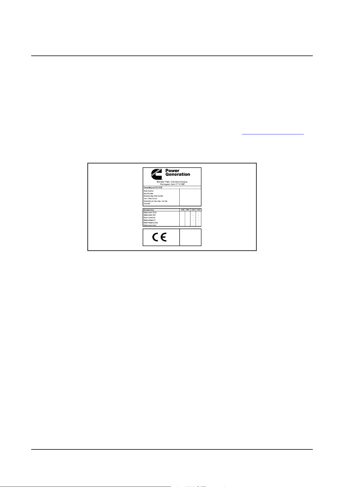
3.1 Generator Set Identification
Each generator set is provided with a nameplate similar to that shown below. The nameplate provides
information unique to the generator set.
3.1.1 Generator Set Rating
Refer to the generator set nameplate for generator set rating. Refer to Section 5.4 on page 70 for
operation at temperatures or altitudes above those stated on the nameplate.
3.1.2 Nameplate - Open Generator Set
FIGURE 1. TYPICAL OPEN GENERATOR SET NAMEPLATE
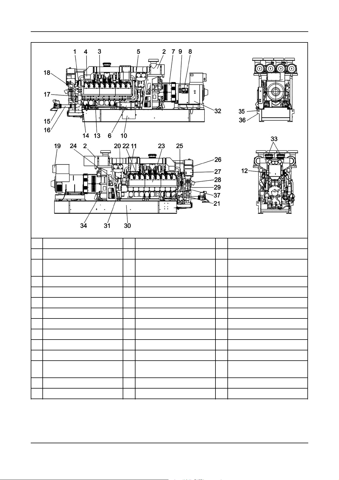
3.2 Generator Set Components
The main components of a typical QSV91G engine generator set are shown below, and referred to
within this section.
There are various options listed although they may not be available for all models.
170908-0209 (Issue 6)
Copyright © 2016 Cummins Inc.
Page 24
3. System Overview 3-2016
No Description No Description No Description
1 Gas Mass Flow Valve 14 Lube-oil Make-up Valve 27 CENSE Module
2 Air Filter 15 DSSOV Solenoid Shut Off
Valve
3 Turbocharger 16 Gas Pipe 29 Low Temp Water Coolant pipe
4 Fuel/Air Mixer 17 Vent Valve 30 Steel Bedframe
5 Gas Mass Flow Valve 18 Centrifugal Oil Filter 31 Electric Starter Motor
6 Crankcase Breather Filter 19 AVR/Controls Box 32 AC Auxiliaries Box
7 Alternator 20 Lube Oil Filters 33 Exhaust Bellows
8 Generator Set Terminal Box 21 Coolant Water Pump 34 Gearbox
9 Generator Set Dataplate 22 Spark Plugs & Ignition Coils 35 Lifting Point
10 Dirty Oil Leak-off Tank 23 Multihousing Cover 36 Jacking Point
11 Engine Dataplate 24 Lube Oil Cooler Coolant Return
Pipe
12 Aftercooler 25 Flotech Gas Valve
13 Lube-oil Dipstick 26 Governor Driver Modules
FIGURE 2. TYPICAL QSV91G ENGINE GENERATOR SET
28 Governor Actuator Module
37 High Temp Water Coolant pipe
Copyright © 2016 Cummins Inc.
18 0908-0209 (Issue 6)
Page 25
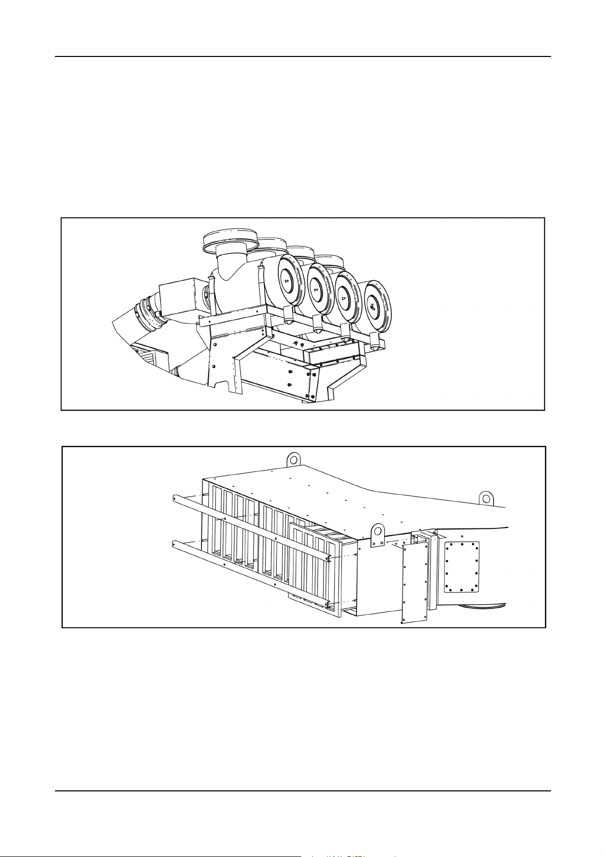
3.3 Air Cleaner
An air cleaner includes an element that must be replaced periodically. Some air cleaners include a
service indicator that indicates when an air cleaner element is dirty and must be replaced.
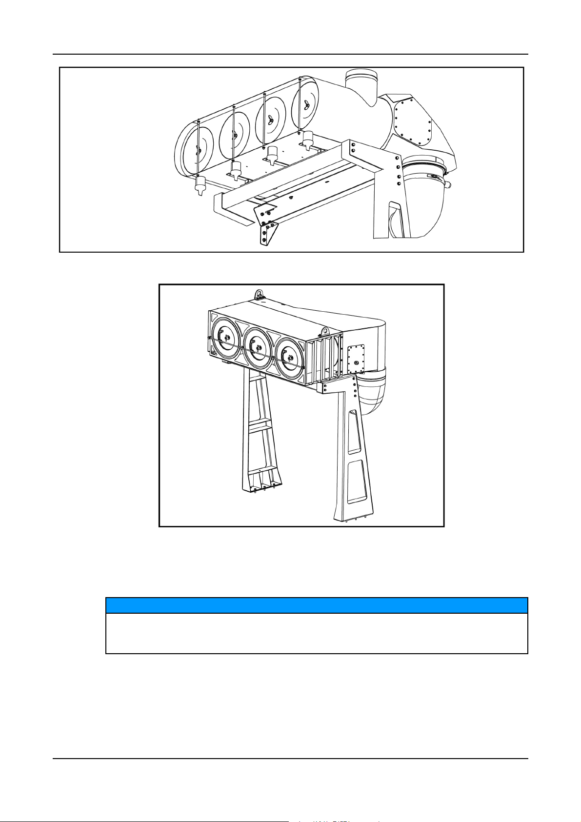
3.3.1 Air Cleaner System
An air cleaner is used to filter particles from the air supply to the engine. Regular maintenace is critical
in achieving optimum performance of the generator set.
Depending on the requirements, one of the following air cleaner systems will be fitted on the generator
set.
3. System Overview3-2016
FIGURE 3. AIR CLEANER ASSEMBLY
FIGURE 4. AIR CLEANER ASSEMBLY
190908-0209 (Issue 6)
Copyright © 2016 Cummins Inc.
Page 26
3. System Overview 3-2016
FIGURE 5. AIR CLEANER ASSEMBLY
FIGURE 6. AIR CLEANER ASSEMBLY
3.4 Coolant Specification
Incorrect coolant concentration or level may allow an engine to overheat without protection
of shutdown device, and cause severe damage to the engine. Maintain coolant level for
proper operation of high engine temperature shutdown system.
It is important that the quality of coolant used in Cummins engines meets the Cummins recommended
specifications (Consult your authorised distributor). A premixed fully formulated coolant or a 50/50
mixture of high quality water and fully formulated concentrated anti-freeze must meet Cummins
Engineering Standard 14603.
Cummins recommend the use of Fleetguard®Antifreeze Coolant ES Compleat containing DCA4 Plus.
Copyright © 2016 Cummins Inc.
NOTICE
20 0908-0209 (Issue 6)
Page 27
For filling and maintenance of Cooling Systems refer to the Operation and Maintenance Manual, or
consult your authorised distributor.
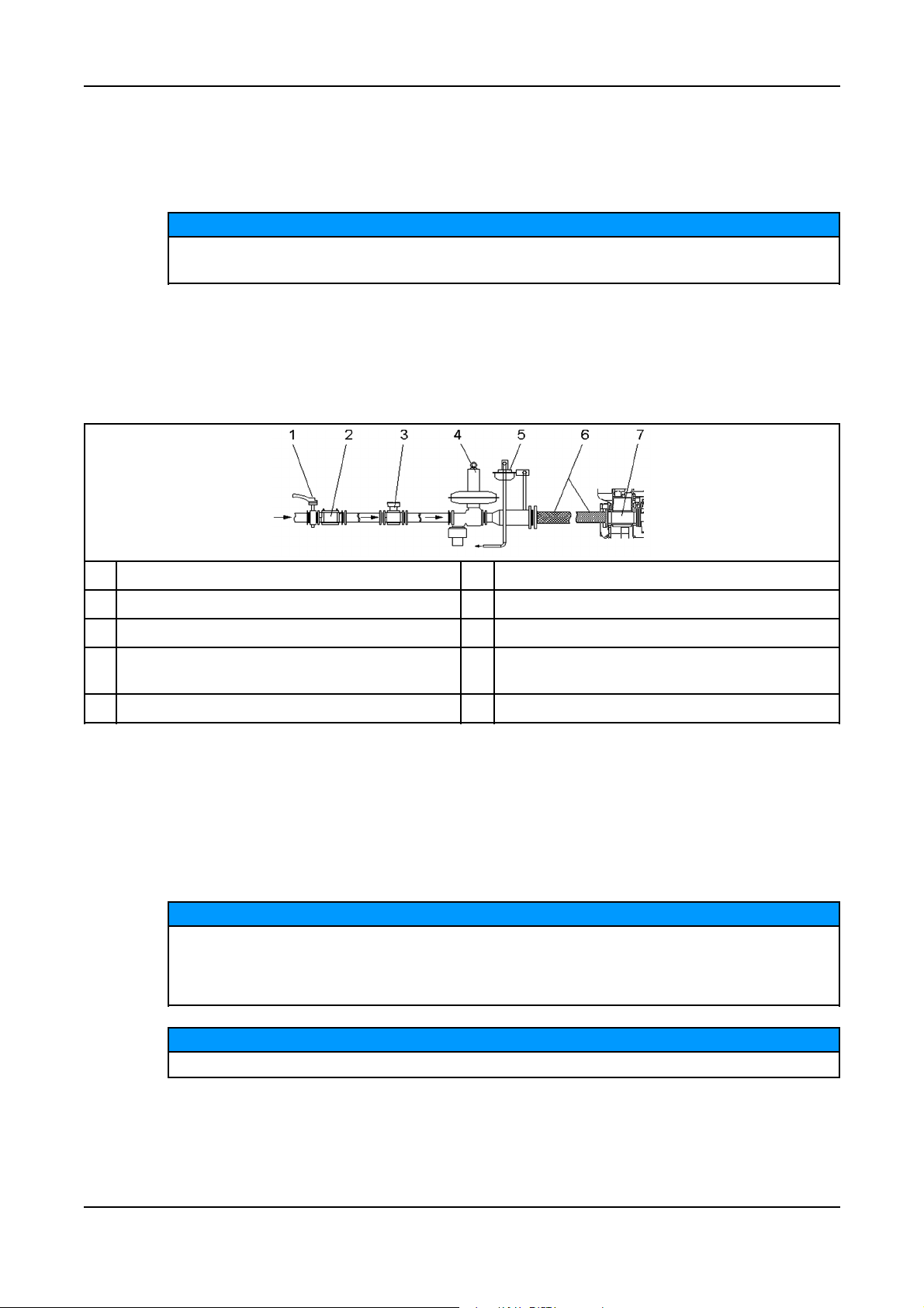
3.5 Gas Train
Installation, maintenance and testing of gas pipe work system must be carried out by suitably
trained and experienced personnel.
Natural Gas is supplied to the engines’ fuel management system through a flexible pipe attached to a
gas train. The gas train includes a main shut-off valve and other gas control components. Control
equipment for the fuel/air ratio and engine speed, are provided on the generator set.
A typical gas train, starting at the gas main supply point, includes the components shown below.
3. System Overview3-2016
NOTICE
No Description No Description
1 Gas Shut-off Valve (GSOV) 5 Pressure Relief Valve (PRV)
2 Filter 6 Flexible Pipe
3 Flowmeter (optional) 7 Double Block & Double Solenoid Shut Off Valve
(DSSOV) (Mounted off-genset - Option)
4 Pressure Regulator
FIGURE 7. TYPICAL GAS TRAIN
3.6 Heaters
3.6.1 Heater Supply and Isolation
A power supply is required for the operation of the engine, coolant, and alternator heaters (if fitted).
NOTICE
It is the sole responsibility of the customer to provide the power supply and the means to
isolate the AC input to the terminal box. Cummins Power Generation accepts no
responsibility for providing the means of isolation. Contact your distributor for more
information.
NOTICE
This disconnecting device is not provided as part of the generator set.
210908-0209 (Issue 6)
Copyright © 2016 Cummins Inc.
Page 28
3. System Overview 3-2016
3.7 Mains (Utility) Powered Battery Charger
CAUTION
Hazardous Voltage
Contact with high voltages can cause severe electrical shock, burns, or death.
Disconnect the battery charger before isolating the battery.
This unit maintains the battery in a fully charged condition without over-charging. The unit also
provides rapid charging, when necessary, at a current up to the rated output.
The charger’s electronic control circuit allows the charger to be left in circuit during engine cranking
and to operate in parallel with the charge alternator.
The charger will supply current to the battery system until the battery terminal voltage becomes equal
to the set float voltage, at which point only a trickle charge current is present. When the battery
becomes discharged due to a load being present and the terminal voltage falls, the charger will again
supply current to restore the voltage of the battery to the float voltage.
3.8 Oil Specification
NOTICE
High quality engine oil, approved by Cummins should be used only. The use of unapproved
oil may cause severe damage to the engine.
Selecting and using the correct grade of engine oil is critical for achieving engine service life, engine
reliability and performance.
It is important to understand that the generator set must be operated and maintained in accordance to
Cummins published recommendations. Failure to follow applicable service intervals and
recommendations in the Operation and Maintenance Manual applicable to the engine can result in
severe engine damage. Consult your authorised distributor for more information.
Use high-quality SAE40 (mono-grade) NG engine oils, such as Valvoline® Premium Blue GEO LA or
its equivalent. The use of the ‘Premium Grade – Long Change Interval’ oils are strongly
recommended. The SAE40 oils approved for use in Cummins HHP natural gas fuelled engines are as
follows:
TABLE 1. QSV91G 2MWE ENGINE (18.2BAR BMEP MODELS): C2000 N5C, C2000 N6C
Manufacturer Oil Names Grade TBN Sulphated Ash %
Manufacturer Oil Names Grade TBN Sulphated Ash %
Mobil Pegasus 805* SAE40 6.2 0.54
Valvoline Premium Blue GEO
LA*
SAE40 5.5 0.44
Valvoline Premium Blue GEO
MA*
Shell Mysella XL* SAE40 4.5 0.48
*Premium grade oil
Copyright © 2016 Cummins Inc.
SAE40 7.2 0.7
22 0908-0209 (Issue 6)
Page 29

3. System Overview3-2016
TABLE 2. QSV81/91G ENGINE (14 & 16BAR BMEP MODELS): C1540 N5C, C1750 N5C, C1250 N6C, C1540
N6C, C1750 N6C, C1700 N6
Manufacturer Oil Names Grade TBN Sulphated Ash %
Mobil Pegasus 805* SAE40 6.2 0.54
Mobil Pegasus 705 SAE40 5.6 0.52
Elf Nateria MH40 SAE40 5.2 0.45
Shell Mysella LA SAE40 5.0 0.45
Shell Mysella XL* SAE40 4.5 0.48
Caltex Geostar LA SAE40 5.2 0.49
Valvoline Premium Blue GEO
SAE40 5.5 0.44
LA*
*Premium grade oil
TABLE 3. QSK60G ENGINE (MULTI AND SINGLE-TURBOCHARGER MODELS): C995 N5C, C1160 N5C,
C1200 N5C, C1400 N5C, C1000 N6C, C1100 N6C, C1400 N6C, C1000 N6, C1250 N6, C1350 N6
Manufacturer Oil Names Grade TBN Sulphated Ash %
Mobil Pegasus 805* SAE40 6.2 0.54
Valvoline Premium Blue GEO
SAE40 5.5 0.44
LA*
Shell Mysella XL* SAE40 4.5 0.48
*Premium grade oil
Regularly sample the oil and perform oil analysis. If regular oil analysis is not performed, then the oil
change interval is reduced and oil analysis must be carried out immediately prior to the oil change to
determine that the oil contamination was within acceptable limits at the time of the oil change. Refer to
the engine specific Operation and Maintenance manual for guidance on intervals and procedures.
3.8.1 Low BTU Gas Engines
Cummins Inc., recommends the use of a high quality SAE40 lubricating oil specifically formulated for
use in Low BTU and aggressive gaseous fueled engines.
Various lubricating oil brands are available worldwide and careful selection is required to match the
product with the type of fuel in use. Cummins Inc. has Low BTU engines operating experience with
ChevronTexaco and ExxonMobil who offer a wide range of products for the various categories of fuel.
The more acidic fuel sources require oil with a higher Total Base Number (TBN) to protect the engine.
Supplier Product Fuel
Chevron Texaco (Caltex) Geotex LA
Geotex HD
Geotex LF
®
®
®
Geotex HDAX LA
Geotex HDAX LFG
ExxonMobil Pegasus 805
Pegasus 605
Pipeline Natural Gas
Non-Pipeline Natural Gas
Non-Pipeline Natural Gas
®
®
®
®
230908-0209 (Issue 6)
Natural Gas
Non-Pipeline Natural Gas
Natural Gas
Non-Pipeline Natural Gas
Copyright © 2016 Cummins Inc.
Page 30

3. System Overview 3-2016
Supplier Product Fuel
Pegasus 610
®
Non-Pipeline Natural Gas
3.9 Sensors
Various generator set parameters are measured by sensors, and the resulting signals are processed
by the control board.
Engine-mounted sensors monitor a number of different systems, such as:
• Lube Oil Pressure
• Cooling System Temperature
3.10 System Options
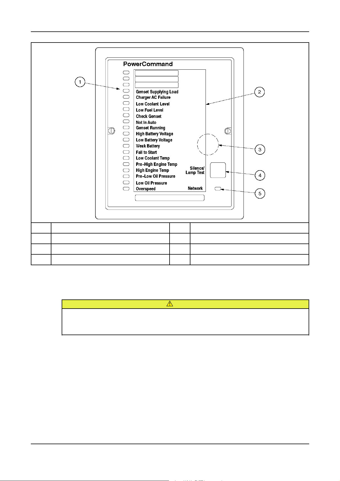
3.10.1 PowerCommand Universal Annunciator
A universal annunciator provides lamps and a horn to annunciate the operating status and fault
conditions of an emergency power system. It is designed for connection to either a 12 VDC or a 24
VDC control system. It can be configured to be either a positive or negative signal device.
Two versions of the PowerCommand universal annunciator are available.
• Panel Mounted
• Panel with Enclosure
The universal annunciator can communicate using either a PCCNet or a Modbus network.
Refer to the annunciator owner's manual for more information.
Copyright © 2016 Cummins Inc.
24 0908-0209 (Issue 6)
Page 31
3. System Overview3-2016
No. Description No. Description
1 System Status Lamps 4 Silence/Lamp Test Button
2 Insert Card 5 Network Status Lamp
3 Horn
FIGURE 8. ANNUNCIATOR COMPONENTS
3.10.2 Mains (Utility) Powered Battery Charger
CAUTION
Hazardous Voltage
Contact with high voltages can cause severe electrical shock, burns, or death.
Disconnect the battery charger before isolating the battery.
This unit maintains the battery in a fully charged condition without over-charging. The unit also
provides rapid charging, when necessary, at a current up to the rated output.
The charger’s electronic control circuit allows the charger to be left in circuit during engine cranking
and to operate in parallel with the charge alternator.
The charger will supply current to the battery system until the battery terminal voltage becomes equal
to the set float voltage, at which point only a trickle charge current is present. When the battery
becomes discharged due to a load being present and the terminal voltage falls, the charger will again
supply current to restore the voltage of the battery to the float voltage.
250908-0209 (Issue 6)
Copyright © 2016 Cummins Inc.
Page 32

3. System Overview 3-2016
3.10.3 Coolant Heater
NOTICE
Operating the heater or heaters when the coolant system has been drained, or there is a
suspicion that the coolant is frozen, can result in equipment damage.
Always make sure the coolant is not frozen and the radiator is filled to the recommended
level before energizing the heater, or heaters.
A coolant heater keeps the engine coolant warm when the engine is shut down. It heats and circulates
the coolant within the engine. This reduces start-up time and lessens engine wear caused by cold
starts. It is electrically operated and thermostatically controlled.
FIGURE 9. TYPICAL COOLANT HEATER
Copyright © 2016 Cummins Inc.
26 0908-0209 (Issue 6)
Page 33

4 Control System - PowerCommand 3.3
4.1 Control System Description
The control system is used to start and stop the generator set from the display screen in either Manual
or Auto mode. It is suitable for stand alone or paralleling generator sets in both standby and primepower applications, providing full generator set monitoring capability and protection. It monitors the
engine for temperature, oil pressure and speed, and provides voltage and current metering. In the
event of a fault the unit indicates the fault type and automatically shuts down the generator set on
critical faults.
All indicators, control buttons and the display screen are on the face of the operator panel as
illustrated in the following figure.
There are two fault level signals generated by the control system as follows:
• Warning: signals an imminent or non-critical fault for the engine. The control provides an
indication only for this condition.
• Shutdown: signals a potentially critical fault for the engine. The control immediately takes the
engine off-load and automatically shuts it down.
The standard control system operates on 12 or 24 VDC battery power. The auxiliary equipment
operates on LV AC power. The history data is stored in non-volatile memory and is not deleted if
battery power is lost.
4.1.1 Control System Panel
No Description
1 Operator Panel
2 Bargraph Meter Panel
3 Alarm Module
4 Emergency Stop Button
5 Isolator Switch
FIGURE 10. TYPICAL CONTROL SYSTEM PANEL
270908-0209 (Issue 6)
Copyright © 2016 Cummins Inc.
Page 34

4. Control System - PowerCommand 3.3 3-2016
4.1.2 Operating Modes
The PowerCommand®3.3 control is operated by the Start/Stop/Manual/Auto buttons on the Operator
Panel. Refer to Figure 11 on page 31.
NOTICE
If the Mode Change access feature is enabled, a password is required to use these buttons to
change the mode of operation. Contact your authorized distributor for options.
4.1.2.1 Stop Button
Press this button to put the generator set into the Off mode. This disables Auto and Manual modes.
The green lamp above this button lights when the generator set is in the Off mode.
If the generator set is running, in either Manual or Auto mode, and the Stop button is pressed, the
engine shuts down.
Refer to Section 4.12 on page 64 for more information on stopping in Auto or Manual mode.
NOTICE
If possible, hot shutdown under load should be avoided to help prolong the reliability of the
generator set.
4.1.2.2 Manual Button
Press this button to put the generator set into the Manual mode. The Start button must then be
pressed within ten seconds. Failure to do this results in the control mode defaulting, putting the
generator set into the Off mode.
The green lamp above this button is lit when the generator set is in Manual mode.
If Mode Change access password feature is enabled, the password must be entered before
pressing the Start button. See Section 4.12.1.
4.1.2.3 Start Button
NOTICE
When the Manual button is pressed, this Start button must be pressed within ten seconds to start the
generator set. The generator set starts up normally but without the Time Delay to Start.
In other modes, this button has no effect.
If the Start button is not pressed within the ten seconds of pressing the Manual button, the
generator set mode changes to the Off mode automatically.
Copyright © 2016 Cummins Inc.
NOTICE
28 0908-0209 (Issue 6)
Page 35

4.1.2.4 Auto Button
Press this button to put the generator set into the Auto mode. In this mode, the generator set is
controlled by a remote switch or device (e.g. transfer switch).
The green lamp above this button lights when the generator set is in Auto mode.
4.1.2.5 Battle Short Mode
Automated Machinery
Battle Short mode overrides some parameters of generator set control. Unmonitored
generator sets can cause a fire or electrical hazard, resulting in severe personal injury or
death.
Make sure that the operation of the set is supervised during Battle Short operation.
Battle Short mode is not a distinct mode of operation. The PowerCommand®control is still in the Off,
Manual, or Auto mode while Battle Short mode is active. The PowerCommand®control still follows the
appropriate sequence of operation to start and stop the generator set. Battle Short mode is a
generator set mode of operation that prevents the generator set from being shutdown by all but a few,
select, critical shutdown faults.
4. Control System - PowerCommand 3.33-2016
WARNING
The purpose of Battle Short mode is to satisfy local code requirements, where necessary. To use this
feature, the necessary software must be installed at the factory when the PowerCommand®control is
purchased. Only authorized service personnel can enable this feature. When shipped from the factory,
this feature is disabled.
NOTICE
The Battle Short feature must be enabled or disabled using the InPower service tool.
This feature must only be used during supervised, temporary operation of the generator set. The faults
that are overridden when in Battle Short mode can affect generator set performance, or cause
permanent engine, alternator or connected equipment damage.
NOTICE
If this mode of operation is selected, the protection of load devices will be disabled.
Cummins Power Generation will not be responsible for any claim resulting from the use of
this mode.
NOTICE
All shutdown faults, including those overridden by Battle Short, must be acted upon
immediately to ensure the safety and well being of the operator and the generator set.
Battle Short is turned on or off with an external switch connected to one of the two customer
configured inputs or a soft switch on the operator panel.
When enabled, Battle Short switch input can be set using a Setup menu. To turn Battle Short mode
on using the soft switch in the operator panel, Battle Short must be set to Operator Panel and
enabled using the InPower service tool (default is Inactive).
When Battle Short mode is enabled, the Warning status indicator lights and code "1131 – Battle Short
Active" is displayed.
290908-0209 (Issue 6)
Copyright © 2016 Cummins Inc.
Page 36

4. Control System - PowerCommand 3.3 3-2016
When Battle Short mode is enabled and an overridden shutdown fault occurs, the shutdown lamp
remains lit even though the set continues to run. "Fault code 1416 – Fail to Shutdown" is displayed. If
the fault is acknowledge, the fault message is cleared from the display but remains in the Fault History
file as long as Battle Short mode is enabled.
Battle Short is suspended and a shutdown occurs immediately if any of the following critical shutdown
faults occur:
• Speed Signal Lost (Loss of Speed Sense) - Fault code 121
• Overspeed - Fault code 234
• Local Emergency Stop - Fault code 1433
• Remote Emergency Stop - Fault code 1434
• Excitation Fault (Loss of Voltage Sense) - Fault code 2335
Or
The Battle Short feature is disabled after an overridden shutdown fault occurred while in Battle Short
mode. Fault code "1123 – Shutdown After Battle Short" is then displayed.
4.1.3 Power On and Sleep Modes
The operating modes of the control panel and operating software are Power On and Sleep.
Power On Mode
In this mode, power is continuously supplied to the control panel. The control’s operating software and
control panel lamps/graphical display remain active until the Sleep mode is activated.
Sleep Mode
Sleep mode is used to reduce battery power consumption when the control is not being used and it is
in the Off or Auto mode. In this mode, the control’s operating software is inactive and the lamps and
graphical display on the control panel are all off.
When all conditions are met (i.e. no unacknowledged faults and the control is in the Off/Auto mode),
the sleep mode activates after five minutes of keypad inactivity. This length of time is configurable.
To activate the control and view the menu display without starting the generator set, press any control
button.
Sleep mode can be enabled/disabled, contact your authorized distributor for options.
4.2 Operator Panel
Figure 11 shows the features of the front panel. It includes five lamp indicators; the graphical display
with four menu select and seven menu navigation buttons; and six control mode buttons. This display
panel enables the operator to look at the status, adjust the settings, and start and stop the generator
set.
NOTICE
Copyright © 2016 Cummins Inc.
30 0908-0209 (Issue 6)
Page 37

4. Control System - PowerCommand 3.33-2016
No. Description No. Description
1 Indicator Lamp – Warning 11 Circuit Breaker – Closed Button
2 Indicator Lamp – Shutdown 12 Circuit Breaker – Open Button
3 Indicator Lamp – Genset Running 13 Manual Button
4 Indicator Lamp – Remote Start 14 Previous Menu Button (or Clear)
5 Indicator Lamp – Not in Auto 15 Item Select Button (OK)
6 Lamp Test Button 16 Menu Navigation Buttons (Up, Down, Left, Right)
7 Reset Button 17 Home Button
8 Auto Mode Button 18 Menu Select Buttons (for use with Item 19)
9 Start Button 19 Graphical Display
10 Stop Button
FIGURE 11. OPERATOR PANEL
4.2.1 Selection Buttons
Four momentary buttons are used to navigate and change the selection in the graphical display.
Press the OK button to select the item that is currently highlighted in the graphical display:
• If the selected item is a menu item, this opens the sub-menu or screen.
• If the selected item is a parameter, this lets you adjust the parameter (if possible) or prompts you
for a password.
• If the selected item is a value you have just adjusted, this saves the change.
• If the selected item is an action, the graphical display runs the action or prompts you for a
password.
310908-0209 (Issue 6)
Copyright © 2016 Cummins Inc.
Page 38

4. Control System - PowerCommand 3.3 3-2016
4.2.2 Default Settings
The Operator Panel can display SAE or Metric units of measurement and should be set during the
initial setup of the generator set. Only trained and experienced personnel are allowed to change the
default setting. Contact your authorized distributor.
4.2.3 Lamp Indicators
Figure 11 on page 31 shows the front panel of the Operator Panel with the five lamp indicators.
4.2.3.1 Warning
This amber lamp is lit whenever the control detects a Warning condition. This lamp is automatically
shut off when the Warning condition no longer exists.
4.2.3.2 Shutdown Status
This red lamp is lit when the control detects a Shutdown condition. The generator set cannot be
started when this lamp is on. After the condition has been corrected, the lamp can be reset by first
pressing the Stop button and then the Reset button.
4.2.3.3 Not in Auto
This red lamp is lit when the control is not in Auto.
4.2.3.4 Remote Start
This green lamp indicates the control is receiving a Remote Run signal. The Remote Run signal has
no effect unless the generator set is in Auto.
4.2.3.5 Generator Set Running Lamp
The green lamp is lit when the generator set is running at, or near, rated speed and voltage. This is
not lit while the generator set is warming up or cooling down.
4.2.4 Lamp (LED) Test Button
Press this button to test the lamps (LEDs). All of the lamps should turn on for five seconds.
Press and hold this for three seconds to turn on or off (to toggle) an external panel lamp.
4.2.5 Reset Button
Press this to reset any active faults.
If the condition(s) that caused an existing shutdown fault still exists, the generator set generates the
fault again.
If the condition(s) that caused an existing warning fault still exists, the generator set generates the
fault again, but the operator panel stops displaying it in the graphical display.
4.2.6 CB Open Button
The circuit breaker open button is used in Manual mode only. When pressed, it enables the
generator set circuit breaker to open and disconnect from the load.
Copyright © 2016 Cummins Inc.
32 0908-0209 (Issue 6)
Page 39

4.2.7 CB Closed Button
The circuit breaker closed button is used in Manual mode only. When pressed it enables the
generator set circuit breaker to close when the set is up to speed and voltage and therefore, ready to
accept the load.
NOTICE
This button has no effect unless the bus is dead, or the generator set is synchronized with
the other source.
4.2.8 Graphical Display and Buttons
Figure 12 on page 33 shows the graphical display and the relevant menu selection buttons.
The graphical display is used to view menus of the menu-driven operating system. System messages
(communication, event, and fault) are also shown on the display.
Four momentary soft-key buttons (item 5) are used to change menus, or pages within each screen.
These selection buttons are “active” when any text or the up and down triangles (▲ and ▼ in Section
4) are displayed in the graphical display. Some sub-menus do not include any active buttons.
4. Control System - PowerCommand 3.33-2016
Use the graphical display to view event/fault information, status, screens, and parameters.
Display Panel Description
Section 1 Control status
Section 2 Active fault or screen name
Section 3 Relevant data to Section 2
Section 4 Additional functions and page up or down availability
Buttons 5 Selection buttons relevant to Section 4
Buttons 6 Selection change or accept buttons
FIGURE 12. GRAPHICAL DISPLAY WITH TYPICAL SCREENSHOT
330908-0209 (Issue 6)
Copyright © 2016 Cummins Inc.
Page 40

4. Control System - PowerCommand 3.3 3-2016
4.2.8.1 Section 1 - Control Status
Section 1 displays the status of the controller.
Status Description
Ready This is the default state. The controller is ready to start the generator set, or it has started
one of the start sequences but has not started the engine yet.
Starting The controller is starting the engine in one of the start sequences, and the engine speed is
greater than zero.
Idle Warmup The controller is raising the engine speed to idle speed, or the engine is running at idle
speed in one of the start sequences.
Rated Freq and
Voltage
Idle Cooldown The controller is reducing the engine speed to idle speed, or the engine is running at idle
Stopping The controller is stopping the engine, and the engine speed is still greater than zero.
Emergency Stop There is an active shutdown fault.
Setup Mode The controller is in Setup mode.
Wait to Powerdown The controller is ready to enter Powerdown mode, but another device is sending a System
Off The controller is in the process of entering power-down mode. The controller is performing
Demo Mode The controller is running a demonstration. Every screen is available in the demonstration,
The controller is raising the engine speed to rated speed; the generator set is running at
rated speed and voltage; or the controller has started one of the stop sequences but has not
started reducing the engine speed yet.
speed in one of the stop sequences.
Wakeup signal.
some last-second checks.
and any changes you make in the demonstration will have no effect on the controller. To
end the demonstration, the Operator Panel must be turned off.
4.2.8.2 Section 2 - Active Fault or Screen Name
Section 2 displays the screen name and information about the last active shutdown fault. If there are
no active shutdown faults, it displays the last active warning fault.
If there is an active fault, the operator panel displays the following information about it:
• Fault type
• Event/fault code
• Name of the controller that detected the fault e.g. the engine ECM unit. This is blank if the
controller detected the fault
• Fault name.
If you press the Reset button, the operator panel stops displaying active warning faults, even if the
condition(s) that caused the fault(s) has not been corrected. The Warning LED remains on, however.
The operator panel always displays any active shutdown faults, even if the Reset button is pressed.
Fault Type Description
Warning This is a warning fault. (See Chapter 7 on page 123)
Derate This is a derate fault. (See Chapter 7 on page 123)
Shutdown This is a shutdown fault that initiates a Shutdown Without Cooldown sequence. (See
Chapter 7 on page 123)
Shutdown with
Cooldown
Copyright © 2016 Cummins Inc.
This is a shutdown fault that initiates a Shutdown With Cooldown sequence
34 0908-0209 (Issue 6)
Page 41

4. Control System - PowerCommand 3.33-2016
4.2.8.3 Section 3 - Interactive Screen or Menu
Section 3 shows information relevant to Section 2. You can view the operating values for the
generator set, navigate through screen and adjust parameters (if permitted).
The default screen is the Genset Data screen.
The following table explains how the operator panel displays when the value of a specific parameter is
missing, unexpected, or outside the range allowed for the parameter.
Operator Panel Description
NWF Network Failure - There is a PCCNet network failure or a CAN (ECM) failure
OORL Out Of Range Low - The value is less that the lowest allowed value for this parameter
OORH Out Of Range High - This value is greater that the highest allowed value for this parameter
-- -- -- This value is not applicable
4.2.8.4 Section 4 - Additional Functions Indicators
Section 4 indicates if additional information or further sub-menus are available by up or down arrows
(▲ and ▼). If that particular page or menu has no additional information, then no arrow will be visible
at this time.
For example if the graphical display is not big enough to display the screen at one time an up and/or
down arrow (▲ and ▼) will be visible. Press the appropriate selection button beneath the graphical
display to look at the previous or next page of information in that screen.
4.2.8.5 Menu Navigation Buttons
Four momentary buttons are used to navigate and change the selection in the graphical display.
Press the OK button to select the item that is currently highlighted in the graphical display:
• If the selected item is a menu item, this opens the sub-menu or screen.
• If the selected item is a parameter, this lets you adjust the parameter (if possible) or prompts you
for a password.
• If the selected item is a value you have just adjusted, this saves the change.
• If the selected item is an action, the graphical display runs the action or prompts you for a
password.
4.3 Operator Panel - Initial Operator Menu
Figure 13 on page 37 shows the initial menu which is displayed over two pages. Use the soft-key
buttons below the up and down arrows (▲ and ▼) to toggle between the two pages.
Use the soft-key buttons below Genset, Alternator, or Engine to short-cut to those menus.
Pressing the Home button from any screen will return the display to the main menu screens.
4.3.1 Initial Menu Data
This menu displays the information available through the menus.
350908-0209 (Issue 6)
Copyright © 2016 Cummins Inc.
Page 42

4. Control System - PowerCommand 3.3 3-2016
TABLE 4. INITIAL MENU DATA
Name Description
History/About Use this screen to view historical information about your generator set.
Faults: If there are no active Faults, these screens will not be available.
Active Shutdowns Use this screen to view active Shutdown faults.
Active Warning Use this screen to view active Warning faults.
History Use this screen to view faults that have been cleared.
Paralleling Status Use this screen to view the bus, circuit breakers, and paralleling states.
Genset Data Use this screen to view the status of the generator set.
Alternator Data Use this screen to view the status of the alternator.
Engine Data Use this screen to view the status of the engine.
Advanced Status:
Genset Use this screen to view power, energy, phase difference, and other detailed
generator set information.
Controller Use this screen to view sequences of operation, configurable inputs and outputs,
and other detailed controller information.
Engine Use this screen to view pressures, voltages, temperatures, and other detailed
engine information.
Help Use this screen to obtain more information regarding the operator panel.
Setup Menus:
Adjust The use of these screens is restricted to authorized personnel only.
Genset Setup
Paralleling Setup
OEM Setup
PCCnet Setup
Modbus Setup
Display Options
Clock Setup
Configurable IO
Calibration
Save/Reserve
Copyright © 2016 Cummins Inc.
36 0908-0209 (Issue 6)
Page 43

4. Control System - PowerCommand 3.33-2016
Press the Home Button to return to the main menu at any time.
Press the C Button to return to the previous menus. Settings will not be saved when this button is pressed.
FIGURE 13. INITIAL OPERATOR MENU
4.4 Operator Panel - Generator Set Data Operator Menu
Figure 14 shows a block representation of a typical Genset Data menu. To navigate from the Home
menu (HOME [1/2]), press the soft-key button below the function button indicating Genset. This will
take you directly to the Genset menu.
The Genset Data menu is displayed on two pages. Use the two soft-key buttons below the up and
down arrows (▲ and ▼) to toggle between the pages.
4.4.1 Generator Set Data
Use this menu to look at the status of the generator set.
370908-0209 (Issue 6)
Copyright © 2016 Cummins Inc.
Page 44

4. Control System - PowerCommand 3.3 3-2016
TABLE 5. GENERATOR SET DATA
PARAMETER DESCRIPTION
Alternator
Genset LL Average Voltage Generator Set Line to Line average voltage
Genset Average Current Generator Set average current
Genset Total kW Generator Set total kW
Genset Total Power Factor Generator Set L1 power factor
Genset Frequency Generator Set frequency
Engine
Engine Running Time Total engine run time
Coolant Temperature Monitor point for the Coolant Temperature
Oil Pressure Monitor point for the Oil Pressure
Allowed values: 0~145 PSI.
Battery Voltage Battery voltage value.
Percent Engine Torque/Duty Cycle Monitor point for the percent engine torque output and
the governor percent duty cycle output when used with
the HM ECM
Allowed values: -125~125%.
Fuel Rate Monitor point for the Fuel Rate
Allowed values: 0~845 liters/hr (223.2 gal/hr)
Fuel Consumption Since Reset Fuel consumption since last reset.
Total Fuel Consumption Total fuel consumption since start of engine.
Genset Application
Genset Application kW rating The Generator Set KW rating.
Genset Application kVA rating The Generator Set KVA rating.
Genset Application Nominal Current The value of the Generator Set application nominal
current.
Genset Standby
Genset Standby kW rating KW rating for the Generator Set in Standby
configuration.
Genset Standby kVA rating KVA rating for the Generator Set in Standby
configuration.
Genset Standby Nominal Current The value of the Generator Set standby nominal
current.
Copyright © 2016 Cummins Inc.
38 0908-0209 (Issue 6)
Page 45

4. Control System - PowerCommand 3.33-2016
Press the Home Button to return to the main menu at any time.
Press the C Button to return to the previous menus. Settings will not be saved when this button is pressed.
FIGURE 14. GENERATOR SET DATA MENU - TYPICAL DATA
4.5 Operator Panel - Engine Data Operator Menu
Figure 15 on page 41 shows a block representation of a typical Engine Data menu. To navigate from
the Home menu (HOME [1/2]), press the soft-key button below the function button indicating Engine.
This will take you directly to the Engine menu.
The Engine Data menu is displayed on one page.
4.5.1 Engine Data
Use this menu to look at the status of the engine.
390908-0209 (Issue 6)
Copyright © 2016 Cummins Inc.
Page 46

4. Control System - PowerCommand 3.3 3-2016
TABLE 6. ENGINE DATA (LBNG GENSET ENABLE IS SET TO DISABLE)
Name Description
Oil Pressure Monitor point for the Oil Pressure
Allowed values: 0~145 PSI.
Boost Pressure Monitor point for the Boost Absolute Pressure
Allowed values: 0~148 PSI.
Coolant Pressure Monitor point for the Coolant Pressure
Allowed values: 0~145 PSI.
Fuel Supply Pressure Monitor point for the Fuel Supply Pressure
Allowed values: 0~145 PSI.
Fuel Outlet Pressure Monitor point for the Fuel Outlet Pressure
Allowed values: 0~36404 PSI.
Crankcase Pressure Monitor point for the Crankcase Pressure
Allowed values: -35.67~38 PSI.
Barometric Absolute Pressure Monitor point for the Barometric Absolute Pressure
Allowed values: 0~37 PSI.
Coolant Temperature Monitor point for the Coolant Temperature
Oil Temperature Monitor point for the Oil Temperature
Allowed values: -40~410 °F.
Intake Manifold Temperature Monitor point for the Intake Manifold Temperature
Allowed values: -40~410 °F.
Fuel Temperature Monitor point for the Fuel Temperature
Allowed values: -40~410 °F.
Aftercooler Temperature Monitor point for the Aftercooler Temperature
Allowed values: -40~410 °F.
Battery Voltage Battery voltage value
Average Engine Speed Monitor point for the Average Engine Speed
Engine Running Time Total engine run time
Glow Plug Command Output of glow plug logic
Allowed values: Driver Off, Driver On.
Oil Pressure Switch Status Low or Not Low.
Allowed values: Not Low, Low.
Copyright © 2016 Cummins Inc.
40 0908-0209 (Issue 6)
Page 47

4. Control System - PowerCommand 3.33-2016
Press the Home Button to return to the main menu at any time.
Press the C Button to return to the previous menus. Settings will not be saved when this button is pressed.
FIGURE 15. ENGINE DATA MENU - TYPICAL DATA
4.5.2 History/About Menu
Figure 16 on page 43 shows a block representation of a typical History/About menu.
To navigate from the Home menu, toggle down until the History/About line of text is highlighted and
press the OK button. This information is displayed over three pages. Use the two soft-key buttons
below the up and down arrows (▲ and ▼) to toggle between the pages.
This screen displays the historical information about the generator set.
TABLE 7. HISTORY/ABOUT
Name Description
Start Attempts (Starts) Total number of start attempts
Allowed values: 0~65535
Total Number of Runs (Runs) Total number of generator set runs
Allowed values: 0~65535
Engine Running Time (Engine
Hours)
Controller On Time (Control
Hours)
Total engine run time in hours
Controller ON time in hours, Upper limit is 136 years
Allowed values: 0~4294967291 hours
Generator Set Total Net (Kw
Hours)
Generator Set Model Number
(Gen Mod #)
Generator Set Serial Number
(Gen Ser #)
Generator set total net kWh accumulation
Allowed values: -2147483648~2147483643 kWh
Number identifying the model of this generator set (Password level: 2)
Serial number identifying this generator set
410908-0209 (Issue 6)
Copyright © 2016 Cummins Inc.
Page 48

4. Control System - PowerCommand 3.3 3-2016
Name Description
Generator Set Nominal
Voltage (Nominal Voltage)
Generator Set Delta/Wye
Connection (Wye/Delta)
Application Rating Select
(Rating Select)
Controller Device Type (Contr
Type)
Calibration Part Number (Calib
Part)
Calibration Revision Date
(Calib Date)
Firmware Version Number
(Contr H/ ver)
Generator set nominal line-line voltage (Password level: 1)
Allowed values: 1~45000 Vac (Default: 1 VAC)
Delta or Wye for generator set connection (Password level: 1)
Allowed values: Delta, Wye (Default: Wye)
Selects generator set's standby/prime/base application rating (Password level: 1)
Allowed values: Standby, Prime, Base (Default: Standby)
Used by the PC Tool
Allowed values: PCC3300, PCC3300 with Masterless Load Demand (MLD)
The unique calibration part number loaded into this control (Password level: 3)
The revision date of the calibration part number loaded into this control
(Password level: 3)
Version of S/W loaded into this control, obtained from PCC Filename
Copyright © 2016 Cummins Inc.
42 0908-0209 (Issue 6)
Page 49
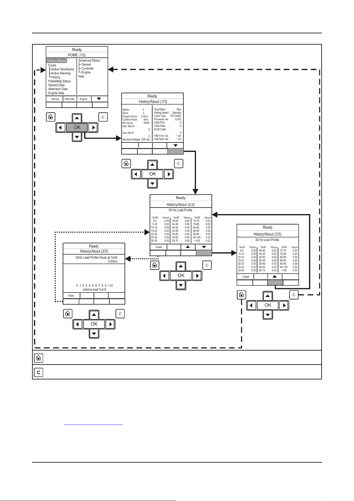
4. Control System - PowerCommand 3.33-2016
Press the Home Button to return to the main menu at any time.
Press the C Button to return to the previous menus. Settings will not be saved when this button is pressed.
FIGURE 16. HISTORY/ABOUT MENU - TYPICAL DATA
4.6 Operator Panel - Alternator Data Operator Menu
Figure 17 on page 46 shows a block representation of a typical Alternator Data menu. To navigate
from the Home menu (HOME [1/2]), press the soft-key button below the function button indicating
Alternator. This will take you directly to the Alternator menu.
The Alternator Data menu is displayed on one page.
430908-0209 (Issue 6)
Copyright © 2016 Cummins Inc.
Page 50

4. Control System - PowerCommand 3.3 3-2016
4.6.1 Alternator Data
Use this menu to look at the status of the alternator. This menu displays line-to-line voltage, line-toneutral voltage, current, and generator set power (in kVA). Some values are not available, dependent
on the number of phases (one or three) and whether or not the application has current transformers.
TABLE 8. ALTERNATOR DATA
Parameter Description
Genset L1L2 Voltage Generator Set L1L2 voltage
Genset L1N Voltage Generator Set L1N voltage
Genset L1 Current Monitors the genset L1 current value
Genset L1 kW Generator Set L1 kW
Genset L1 KVA Generator Set L1 kVA
Genset L1 Power Factor Generator Set L2 power factor
Allowed values: -1.28~1.27 PF
Genset L2L3 Voltage Generator Set L2L3 voltage
Genset L2N Voltage Generator Set L2N voltage
Genset L2 Current Generator Set L2 current
Genset L2 kW Generator Set L2 kW
Allowed values: -32768~32762 kW
Genset L2 KVA Generator Set L2 kVA
Genset L2 Power Factor Generator Set L2 power factor
Allowed values: -1.28~1.27 PF
Genset L3L1 Voltage Generator Set L3L1 voltage
Genset L3N Voltage Generator Set L3N voltage
Genset L3 Current Generator Set L3 current
Genset L3 kW Generator Set L3 kW
Allowed values: -32768~32762 kW
Genset L3 KVA Generator Set L3 kVA
Allowed values: 0~4294967.29 kVA
Genset L3 Power Factor Generator Set L3 power factor
Allowed values: -1.28~1.22 PF
Genset Total kW Generator Set total kW
Genset Total KVA Generator Set total kVA
Genset Total Power Factor Generator Set L1 power factor
Genset Frequency Generator Set frequency
AVR PWM Command The AVR PWM software command. Linear relationship between
counts and % duty cycle with 10000 counts=100% duty cycle
Copyright © 2016 Cummins Inc.
44 0908-0209 (Issue 6)
Page 51

4. Control System - PowerCommand 3.33-2016
Parameter Description
Genset Neutral Current Generator Set neutral current
This is not displayed if the neutral current is not available.
Ground Current Ground current
Alternator Temperatures
NOTICE
Non-Drive End Bearing Temperature
(Aux101)
Drive End Bearing Temperature (Aux101) Monitor point for the Drive End Bearing Temp input from the I/O
Alternator Temperature 1 (Aux101) Monitor point for the Alternator Temp 1 input from the Aux 101 I/O
Alternator Temperature 2 (Aux101) Monitor point for the Alternator Temp 2 input from the Aux 101 I/O
Alternator Temperature 3 (Aux101) Monitor point for the Alternator Temp 3 input from the Aux 101 I/O
Monitor point for the Non-Drive End Bearing Temp input from the
I/O Module.
Allowed values: -65534~65535 °F
Module.
Allowed values: -32767~32762 °F
Module.
Allowed values: -32767~32762 °F
Module.
Allowed values: -32767~32762 °F
Module.
Allowed values: -32767~32762 °F
450908-0209 (Issue 6)
Copyright © 2016 Cummins Inc.
Page 52

4. Control System - PowerCommand 3.3 3-2016
Press the Home Button to return to the main menu at any time.
Press the C Button to return to the previous menus. Settings will not be saved when this button is pressed.
FIGURE 17. ALTERNATOR DATA MENU - TYPICAL DATA
4.7 Operator Panel - Faults and Warnings Menus
The Faults and Warning menu is divided into three main sub-sections; Shutdown Faults (Active
Shutdowns); Warning Faults (Active Warnings); and Faults History (showing up to thirty-two faults that
have been cleared).
4.7.1 Fault Menu
Figure 18 shows a block representation of a typical Fault menu.
To navigate from the Home menu, select the Fault menu from the Home screen.
The fault menu home screen displays, which is divided into three main sub-sections: Active Faults
(Active Shutdowns), Active Warnings, and Faults History. The Faults History screen shows up to
thirty-two faults that have been cleared.
Use the two soft-key buttons below the up and down arrows (▲ and ▼) to toggle between the pages.
TABLE 9. ACTIVE SHUTDOWN FAULTS
Name Description
Index This is the index number of the fault
Fault This is the fault code
Copyright © 2016 Cummins Inc.
46 0908-0209 (Issue 6)
Page 53

4. Control System - PowerCommand 3.33-2016
Name Description
SA Source Address
This is the controller that identified the fault, it is blank if the PCC identified the
fault
Eng Hrs This is how many hours the engine had run (not necessarily continuously) when
the fault was generated
YY/MM/DD This is the date the fault was generated
HH:MM:SS This is the time the fault was generated
Response This is the type of fault that was generated
The name of the fault appears below the rest of the information
Press the Home Button to return to the main menu at any time.
Press the C Button to return to the previous menus. Settings will not be saved when this button is pressed.
FIGURE 18. FAULTS MENU
470908-0209 (Issue 6)
Copyright © 2016 Cummins Inc.
Page 54

4. Control System - PowerCommand 3.3 3-2016
4.7.2 Fault Messages
FIGURE 19. FAULT MESSAGE DISPLAY SCREEN
A Fault message is an indicator of a Warning or Shutdown condition. It includes the fault number, and
a short description. It also includes where the fault occurred if the generator set control did not detect
the fault and is simply reporting the fault. Chapter 7 on page 123 provides a list of the fault codes,
types, and message displayed.
Active and acknowledged faults may be viewed in the Faults menu.
4.7.3 Fault Acknowledgement
Shutdown faults must be acknowledged after the fault has been corrected. If in Auto or Manual mode,
the control must be set to Stop mode (Off). Faults are cleared from the control panel display by
pressing the Reset button.
Faults are re-announced if they are detected again after being acknowledged. Refer to Section 4.2.5
on page 32.
Faults may also be acknowledged when in Auto mode and the Remote Start command is
removed. Contact you authorized distributor for this option.
4.7.4 Warning Fault Menu
Figure 20 shows a block representation of a typical Warning Fault menu.
NOTICE
To navigate from the Home menu, toggle down until the Faults - Warning Fault line of text is
highlighted and press the OK button. This will then display information regarding the current fault. Use
the two soft-key buttons below the up and down arrows (▲ and ▼) to toggle between the pages.
This menu displays up to thirty-two faults. The same event/fault code may appear multiple times if
detected by different sources.
Copyright © 2016 Cummins Inc.
48 0908-0209 (Issue 6)
Page 55

4. Control System - PowerCommand 3.33-2016
TABLE 10. ACTIVE WARNING FAULTS
Name Description
Index This is the index number of the fault
Fault This is the Fault code
SA Source Address
This is the controller that identified the fault, it is blank if the PCC identified the
fault
Eng Hrs This is how many hours the engine had run (not necessarily continuously) when
the fault was generated
HH:MM:SS This is the time the fault was generated.
Response This is the type of fault that was generated.
The name of the fault appears below the rest of the information
490908-0209 (Issue 6)
Copyright © 2016 Cummins Inc.
Page 56

4. Control System - PowerCommand 3.3 3-2016
Press the Home Button to return to the main menu at any time.
Press the C Button to return to the previous menus. Settings will not be saved when this button is pressed.
FIGURE 20. WARNING FAULT MENU - TYPICAL DATA
4.7.5 Faults History Data Operator Menu
Figure 21 on page 51 shows a block representation of a typical Fault History menu.
To navigate from the Home menu, toggle down until the Faults -History line of text is highlighted and
press the OK button. This will then display information regarding the fault(s) history. Use the two softkey buttons below the up and down arrows (▲ and ▼) to toggle between the pages.
This menu displays up to thirty-two faults. The same event/fault code may appear multiple times if
detected by different sources.
Copyright © 2016 Cummins Inc.
50 0908-0209 (Issue 6)
Page 57
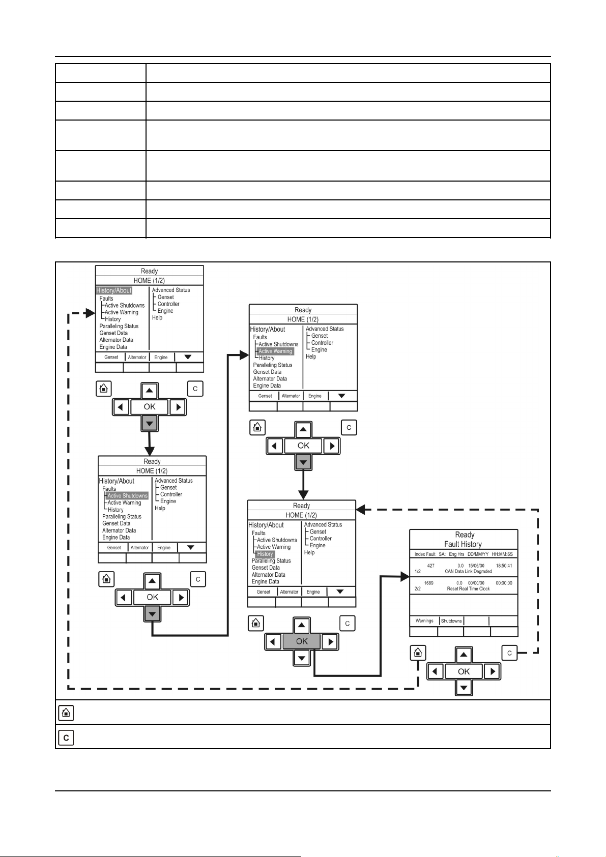
4. Control System - PowerCommand 3.33-2016
Name Description
Index This is the index number of the fault.
Fault This is the Fault code.
SA This is the controller that identified the fault. It is blank if the PowerCommand®3.3 control
identified the fault.
Engine Hrs This is how many hours the engine had run (not necessarily continuously) when the fault
was generated.
MM/DD/YY This is the date the fault was generated.
HH/MM/SS This is the time the fault was generated.
The name of the fault appears below the rest of the information.
Press the Home Button to return to the main menu at any time.
Press the C Button to return to the previous menus. Settings will not be saved when this button is pressed.
FIGURE 21. HISTORY FAULT MENU - TYPICAL DATA
510908-0209 (Issue 6)
Copyright © 2016 Cummins Inc.
Page 58

4. Control System - PowerCommand 3.3 3-2016
4.8 Operator Panel - Adjust Menu
Figure 22 on page 53 shows a block representation of a typical Adjust menu. To navigate from the
Home menu (HOME [1/2]), press the soft-key button below the down arrow in the display window.
This will show the second page of the Home menu (HOME [2/2]). With the Adjust line of text
highlighted, press the OK button to display the information.
The Adjust menu is displayed on one page.
NOTICE
Should any of these settings require amendment or change, please contact your authorized
service center.
NOTICE
You cannot adjust Frequency Adjust or Voltage Adjust if Paralleling Speed Control Mode is
set to Synchronize, Load Share, or Load Govern.
Name Description
Voltage Adjust
Genset LL Average
Voltage
Voltage Adjust A trim that allows the user to add/subtract an offset to the nominal voltage when
Rated/Idle Sw Allowed values: Rated, Idle. Default value: Rated.
Exer Switch Allowed values: Inactive, Active. Default value: Inactive.
Man Warm Byp Allowed values: Normal, Bypass Warmup.
Keyswitch
Keyswitch Status Allowed values: Inactive, Active.
Frequency Adjust
Final Frequency
Reference
Frequency Adjust A method of adding in a frequency offset to the base frequency subject to high and low
Avr Gain A trim that allows the user to modify the overall gains of the AVR. Allowed values:
Generator set Line-to-Line average voltage.
calculating the voltage setpoint. Allowed values: -5~5%. Default value: 0%
The frequency scaled version of the final speed reference. Allowed values: 0~100 Hz.
limit calibrations. Allowed values: -6~6 Hz. Default value: 0 Hz.
0.05~10. Default value: 1
Governor Gain A trim that allows the user to modify the overall gain of the governor. Allowed values:
0.05~10. Default value: 1
Start Delay Allowed values: 0~300 seconds. Default value: 0 seconds.
Stop Delay Allowed values: 0~600 seconds. Default value: 0 seconds.
Copyright © 2016 Cummins Inc.
52 0908-0209 (Issue 6)
Page 59

4. Control System - PowerCommand 3.33-2016
Press the Home Button to return to the main menu at any time.
Press the C Button to return to the previous menus. Settings will not be saved when this button is pressed.
FIGURE 22. ADJUST MENU - TYPICAL DATA
4.9 Operator Panel - Genset Setup Data Operator Menu
Figure 23 on page 54 shows block representations of the Genset Setup Data menu.
Page down to the second page of the Home menu (using the two soft-key buttons below the up and
down arrows [▲ and ▼]). See Section 4.3 on page 35
In the HOME (2/2) menu, using the up and down arrows, toggle down again until the Genset Setup
text is highlighted.
With the Genset Setup line of text highlighted, press the OK button. This will display the Setup Menu.
Use the two soft-key buttons below the up and down arrows [▲ and ▼] to page through the five
pages of the Setup data.
NOTICE
Should any of these settings require amendment or change, please contact your authorized
service center.
530908-0209 (Issue 6)
Copyright © 2016 Cummins Inc.
Page 60

4. Control System - PowerCommand 3.3 3-2016
Press the Home Button to return to the main menu at any time.
Press the C Button to return to the previous menus. Settings will not be saved when this button is pressed.
FIGURE 23. SETUP DATA MENU - TYPICAL DATA
4.10 Operator Panel - Paralleling Status Menu
Figure 24 on page 60 and Figure 25 on page 61 show block representations of a typical Paralleling
Status menu. This screen varies according to the application type. See Section 5.8.3 on page 79.
In the HOME (1/2) menu, using the up and down arrows, toggle down until the Paralleling Status text
is highlighted.
With the Paralleling Status line of text highlighted, press the OK button. This will then display the
Paralleling Status Menu (if the generator set application type is not Standalone).
Copyright © 2016 Cummins Inc.
54 0908-0209 (Issue 6)
Page 61

4. Control System - PowerCommand 3.33-2016
Use the two soft-key buttons below the up and down arrows [▲ and ▼] to page through the six pages
of the Paralleling Status menu.
TABLE 11. PARALLELING STATUS
Parameter Description
ES State Internal paralleling status variable
Allowed values: Standby, Dead Bus, Synchronize, Load Share, Load Govern
Genset LL Average Voltage Generator set line-to-line average voltage
Genset Frequency Generator set frequency
Genset Total kW Generator set total kW
Genset Total kVAR Generator set total kVAR
Genset Total Power Factor Generator set L1 power factor
Genset CB Position Status Indicates generator set breaker position
Allowed values: Open, Closed, Not Available
Phase Match Error Phase error signal for the synchronizer control algorithm
Load Demand Stop Command Indicates status of the final load demand stop command to generator set start
stop control function
Allowed values: Don't Stop, Stop
Genset Bus LL Average
Voltage
Genset Bus Frequency Generator set bus line frequency
Genset Bus Total kW Generator set bus total kW
Genset Bus Total kVAR Generator set bus total kVAR
Genset Bus Total Power
Factor
Synchronizer Status Indicates whether synchronizer is on or off
Bus Status Indicates status of the bus
Permissive Close Allowed Indicates when permissive sync check conditions have been met
Phase Matched Sync check phase match status
Voltage Matched Sync check voltage match status
Frequency Matched Sync check frequency match status
Generator set bus line-to-line average voltage
Generator set bus total power factor
Allowed values: Synchronizer Off, Synchronizer On
Allowed values: Unavailable, Dead, Live
Allowed values: Not Allowed, Allowed
Allowed values: Inactive, Active
Allowed values: Inactive, Active
Allowed values: Inactive, Active
Phase Match Error Phase error signal for the synchronizer control algorithm
Frequency Match Error Frequency match error value used by frequency match PI loop
Voltage Match Error Voltage match error value used by voltage match PI loop
Load Govern kW Target Indicates the final target set point for generator set kW output when paralleled to
utility
550908-0209 (Issue 6)
Copyright © 2016 Cummins Inc.
Page 62

4. Control System - PowerCommand 3.3 3-2016
Parameter Description
Load Govern kVAR Target Indicates the final target set point for generator set kVAR output when paralleled
to utility
Power Factor Setpoint Indicates analog input power factor set point derived from kVAR analog input
Paralleling Speed Control
Mode
Paralleling Voltage Control
Mode
Genset CB Tripped Command Generator set CB tripped command
Genset CB Inhibit Command Generator set CB inhibit command
Load Share %kW Error Indicates %kW error for load sharing control algorithm
Utility CB Tripped Command Utility CB tripped command
Load Share %kVAR Error Indicates %kVAR error for load sharing control algorithm
Utility CB Inhibit Command Utility CB inhibit command
Utility Current Based Breaker
Position
Genset Bus L1L2 Voltage Generator set bus L1L2 voltage
Genset Bus L2L3 Voltage Generator set bus L2L3 voltage
Indicates which speed control algorithm is in effect
Allowed values: Isochronous, Droop, Synchronize, Load Share, Load Govern
Indicates which voltage control algorithm is in effect
Allowed values: Isochronous, Droop, Synchronize, Load Share, Load Govern
Allowed values: Inactive, Active (Default: Inactive)
Allowed values: Inactive, Active (Default: Inactive)
Allowed values: Inactive, Active (Default: Inactive)
Allowed values: Inactive, Active (Default: Inactive)
Indicates utility breaker position based on current
Genset Bus L3L1 Voltage Generator set bus L3L1 voltage
Genset Bus L1N Voltage Generator set bus L1N voltage
Genset Bus L2N Voltage Generator set bus L2N voltage
Genset Bus L3N Voltage Generator set bus L3N voltage
Genset Bus L1 Current Generator set bus L1 current
Allowed values: 0~65530 amps
Genset Bus L2 Current Generator set bus L2 current
Allowed values: 0~65530 amps
Genset Bus L3 Current Generator set bus L3 current
Allowed values: 0~65530 amps
Genset Bus L1 kW Generator set bus L1 kW
Allowed values: -32768~32762 kW
Genset Bus L2 kW Generator set bus L2 kW
Allowed values: -32768~32762 kW
Genset Bus L3 kW Generator set bus L3 kW
Allowed values: -32768~32762 kW
Genset Bus Total kW Generator set bus total kW
Genset Bus L1 kVA Generator set bus L1 kVA
Genset Bus L2 kVA Generator set bus L2 kVA
Genset Bus L3 kVA Generator set bus L3 kVA
Copyright © 2016 Cummins Inc.
56 0908-0209 (Issue 6)
Page 63

Parameter Description
Genset Bus Total kVA Generator set bus total kVA
Genset Bus L1 Power Factor Generator set bus L1 power factor
Allowed values: -1.28~1.22 PF
Genset Bus L2 Power Factor Generator set bus L2 power factor
Allowed values: -1.28~1.22 PF
Genset Bus L3 Power Factor Generator set bus L3 power factor
Allowed values: -1.28~1.22 PF
4. Control System - PowerCommand 3.33-2016
Genset Bus Total Power
Factor
Genset Bus Frequency Generator set bus line frequency
Genset Bus L1 Positive kWh Generator set bus L1 positive kWh accumulation
Genset Bus L2 Positive kWh Generator set bus L2 positive kWh accumulation
Genset Bus L3 Positive kWh Generator set bus L3 positive kWh accumulation
Genset Bus Total Positive
kWh
Genset Bus L1 Negative kWh Generator set bus L1 negative kWh accumulation
Genset Bus L2 Negative kWh Generator set bus L2 negative kWh accumulation
Genset Bus L3 Negative kWh Generator set bus L3 negative kWh accumulation
Genset Bus Total Negative
kWh
Generator set bus total power factor
Allowed values: 0~4294967290 kWh (Default: 0 kWh)
Allowed values: 0~4294967290 kWh (Default: 0 kWh)
Allowed values: 0~4294967290 kWh (Default: 0 kWh)
Generator set bus total positive kWh accumulation
Allowed values: 0~4294967290 kWh (Default: 0 kWh)
Allowed values: 0~4294967290 kWh (Default: 0 kWh)
Allowed values: 0~4294967290 kWh (Default: 0 kWh)
Generator set bus total negative kWh accumulation
Genset Bus Total Net kWh Generator set bus total net kWh accumulation
Genset Bus L1 Positive
kVARh
Genset Bus L2 Positive
kVARh
Genset Bus L3 Positive
kVARh
Genset Bus Total Positive
kVARh
Genset Bus L1 Negative
kVARh
Genset Bus L2 Negative
kVARh
Genset Bus L3 Negative
kVARh
Generator set bus L1 positive kVARh accumulation
Allowed values: 0~4294967290 kVARh (Default: 0 kVARh)
Generator set bus L2 positive kVARh accumulation
Allowed values: 0~4294967290 kVARh (Default: 0 kVARh)
Generator set bus L3 positive kVARh accumulation
Allowed values: 0~4294967290 kVARh (Default: 0 kVARh)
Generator set bus total positive kVARh accumulation
Generator set bus L1 negative kVARh accumulation
Allowed values: 0~4294967290 kVARh (Default: 0 kVARh)
Generator set bus L2 negative kVARh accumulation
Allowed values: 0~4294967290 kVARh (Default: 0 kVARh)
Generator set bus L3 negative kVARh accumulation
Allowed values: 0~4294967290 kVARh (Default: 0 kVARh)
570908-0209 (Issue 6)
Copyright © 2016 Cummins Inc.
Page 64

4. Control System - PowerCommand 3.3 3-2016
Parameter Description
Genset Bus Total Negative
kVARh
Genset Bus Total Net kVARh Generator set bus total net kVARh accumulation
Genset Bus Reset All Energy
Meters Timestamp - Hour
Genset Bus Reset All Energy
Meters Timestamp - Minute
Genset Bus Reset All Energy
Meters Timestamp - Second
Genset Bus Reset All Energy
Meters Timestamp - Day
Genset Bus Reset All Energy
Meters Timestamp - Month
Genset Bus Reset All Energy
Meters Timestamp - Year
Genset Bus L1 kVAR Generator set bus L1 kVAR
Genset Bus L2 kVAR Generator set bus L2 kVAR
Generator set bus total negative kVARh accumulation
Time stamp of when energy meters were last reset
Allowed values: 0~23 (Default: 0)
Time stamp of when energy meters were last reset
Allowed values: 0~59 (Default: 0)
Time stamp of when energy meters were last reset
Allowed values: 0~59 (Default: 0)
Time stamp of when energy meters were last reset
Allowed values: 1~31 (Default: 1)
Time stamp of when energy meters were last reset
Allowed values: 1~12 (Default: 1)
Time stamp of when energy meters were last reset
Allowed values: 0~99 (Default: 0)
Allowed values: -32678~32672 kVAR
Allowed values: -32768~32762 kVAR
Genset Bus L3 kVAR Generator set bus L3 kVAR
Allowed values: -32768~32762 kVAR
Genset Bus L1L2 Phase
Difference
Genset Bus L2L3 Phase
Difference
Genset Bus L3L1 Phase
Difference
Genset Bus L1 kVAh Generator set bus L1 kVAh accumulation
Genset Bus L2 kVAh Generator set bus L2 kVAh accumulation
Genset Bus L3 kVAh Generator set bus L3 kVAh accumulation
Genset Bus Total kVAh Generator set bus total kVAh accumulation
Genset Bus Phase Rotation Generator set bus phase rotation
System Network Termination
Resistor Switch Status
Generator set bus L1L2 voltage phase angle
Generator set bus L2L3 voltage phase angle
Generator set bus L3L1 voltage phase angle
Allowed values: 0~4294967290 kVAh (Default: 0 kVAh)
Allowed values: 0~4294967290 kVAh (Default: 0 kVAh)
Allowed values: 0~4294967295 kVAh (Default: 0 kVAh)
Allowed values: L1-L2-L3, L1-L3-L2, Not Available
Indicates the status of the on-board CAN termination resistor switch (S1)
Load Demand State Indicates the status of load demand operation
PCC3300 MLD controls only
Load Demand Online Capacity Indicates the total amount of online kW bus capacity for load demand
Only generator sets which are eligible for load demand count
PCC3300 MLD controls only
Copyright © 2016 Cummins Inc.
58 0908-0209 (Issue 6)
Page 65

4. Control System - PowerCommand 3.33-2016
Parameter Description
Load Demand Genset Bus
Total kW
Load Demand Surplus
Capacity
Load Demand Total Spare
Capacity Requested
Load Demand Spare Capacity
Available
Load Demand Next Stop
Threshold (kW)
Load Demand Next Start
Threshold (kW)
Load Demand Next Gen to
Start
Load Demand Next Gen to
Stop
Load Demand Initial Delay
Timer
Indicates the total load of system network connected generator sets
PCC3300 MLD controls only
Indicates the amount of unused online kW bus capacity (spinning reserve)
PCC3300 MLD controls only
Indicates the total kW value of all currently active spare capacity requests in the
system
PCC3300 MLD controls only
Indicates when the current load and spare capacity requirements are satisfied
PCC3300 MLD controls only
The kW load at which the next generator set will be stopped
PCC3300 MLD controls only
The kW load at which the next generator set will be started
PCC3300 MLD controls only
Indicates Genset ID of the next generator set to start
PCC3300 MLD controls only
Indicates Genset ID of the next generator set to stop
PCC3300 MLD controls only
Indicates the time remaining before generator sets are allowed to stop after initial
start or after resuming from halted load demand
This timer is set by Load Demand Initial Delay
PCC3300 MLD controls only
Load Demand Start Delay
Timer
Load Demand Stop Delay
Timer
Load Demand Inhibit Local Indicates the status of the Load Demand Inhibit input
Load Demand Genset Status
Table
Genset ID Generator set identifier. All load demand generator sets must have a unique
Load Demand Genset Run
Hours
System Network Datalink
Status
Indicates the time remaining before next generator set is allowed to start
This timer is set by Load Demand Start Delay
PCC3300 MLD controls only
Indicates the time remaining before next generator set is allowed to stop
This timer is set by Load Demand Stop Delay
PCC3300 MLD controls only
When Active all the generator sets will start
PCC3300 MLD controls only
Indicates the load demand priorities and status of all load demand system
network connected generator sets
PCC3300 MLD controls only
Genset ID
PCC3300 MLD controls only
Run hour accumulator used for load demand run hour equalization
This is writable
Allowed Values: 0~999999.9 hours (Default: 0 hours)
PCC3300 MLD controls only
Indicates communication status of the local generator set on system network
(used for load demand)
PCC3300 MLD controls only
590908-0209 (Issue 6)
Copyright © 2016 Cummins Inc.
Page 66

4. Control System - PowerCommand 3.3 3-2016
Parameter Description
Load Demand Spare Capacity
Request Status
Indicates the status of the spare capacity request input
When Active additional spare capacity (set by Load Demand Spare Capacity
Request Value) is requested
PCC3300 MLD controls only
Press the Home Button to return to the main menu at any time.
Press the C Button to return to the previous menus. Settings will not be saved when this button is pressed.
FIGURE 24. PARALLELING STATUS DATA SHEET 1 - TYPICAL DATA
Copyright © 2016 Cummins Inc.
60 0908-0209 (Issue 6)
Page 67

4. Control System - PowerCommand 3.33-2016
Press the Home Button to return to the main menu at any time.
Press the C Button to return to the previous menus. Settings will not be saved when this button is pressed.
FIGURE 25. PARALLELING STATUS DATA SHEET 2 - TYPICAL DATA
4.11 Operator Panel - Paralleling/Basic Setup Menu
Figure 26 on page 63 and Figure 27 on page 64 show block representations of a typical
Paralleling/Basic Setup menu.
To navigate from the HOME (1/2) menu, press the soft-key button below the down arrow in the display
window. This will show the second page of the home menu (HOME 2/2). Using the up and down
arrows, toggle down until the Paralleling/Basic Setup text is highlighted.
With the Paralleling/Basic Setup line of text highlighted, press the OK button. This will then display the
Paralleling/Basic Setup Menu.
610908-0209 (Issue 6)
Copyright © 2016 Cummins Inc.
Page 68

4. Control System - PowerCommand 3.3 3-2016
NOTICE
It is also possible to short-cut to this menu by pressing the soft-key button below the
function button indicating Basic within the Paralleling Status menu.
Use the two soft-key buttons below the up and down arrows [▲ and ▼] to page through the six pages
of the Paralleling/Basic Setup menu.
The adjustment of these submenus is intended for qualified service personnel and site personnel only
and may require a USER password for this operation. If a password is required the USER password
menu will appear when you try to modify the menu. (Refer to Password Menu in Section 4.12.1.1 on
page 64)
NOTICE
Should any of these settings require amendment or change, please contact your authorized
service center.
Copyright © 2016 Cummins Inc.
62 0908-0209 (Issue 6)
Page 69

4. Control System - PowerCommand 3.33-2016
Press the Home Button to return to the main menu at any time.
Press the C Button to return to the previous menus. Settings will not be saved when this button is pressed.
FIGURE 26. PARALLELING/BASIC DATA (SHEET 1 OF 2) - TYPICAL DATA
630908-0209 (Issue 6)
Copyright © 2016 Cummins Inc.
Page 70

4. Control System - PowerCommand 3.3 3-2016
Press the Home Button to return to the main menu at any time.
Press the C Button to return to the previous menus. Settings will not be saved when this button is pressed.
FIGURE 27. PARALLELING/BASIC DATA (SHEET 2 OF 2) - TYPICAL DATA
4.12 Selecting Operating Modes
4.12.1 Passwords and Mode Change Access
4.12.1.1 Entering the Mode Change Access Code
The Mode Change submenus are intended for qualified service personnel and site personnel only,
and by default will require an Access password. If a password is required, the Mode Change – Access
Code menu will appear when you try to switch between Auto, Manual Run, or Stop modes.
Copyright © 2016 Cummins Inc.
64 0908-0209 (Issue 6)
Page 71

4. Control System - PowerCommand 3.33-2016
To enter the mode access code:
1. With the first character highlighted, press the up and down arrow buttons until the required value
is displayed.
2. Press the left arrow button to move to the next numeric character.
3. Repeat steps 1 and 2 until all characters of the Access Code are correct.
4. After you have completed entering the password, press the OK button.
FIGURE 28. MODE CHANGE ACCESS CODE DISPLAY SCREEN
NOTICE
If an incorrect password is entered, the Operator menu that was displayed before Auto,
Manual Run, or Stop mode was selected is re-displayed.
4.12.1.1.1 Passwords
It is possible for the operator to view every parameter in the graphical display; however, a password
may be required before adjustment of a parameter is permitted. The generator set will prompt you if a
password is required and inform you of the level of password required.
Level Description Comment
0 No password None required
1 Operator password Restricted
2 Service password Restricted
3 Engineering password Restricted
4.12.2 Selecting Manual Run Mode
NOTICE
When changing modes, the generator set may start or stop without warning. Make sure there
is no danger to personnel or equipment should the generator set unexpectedly start or stop.
Press the Manual button and then (within ten seconds) the Start button . This bypasses
the 'Time Delay to Start' function and activates the engine control system and the starting system.
If the engine does not start, the starter disengages after a specified period of time and the controller
indicates a 'Fail to Start' shutdown.
650908-0209 (Issue 6)
Copyright © 2016 Cummins Inc.
Page 72

4. Control System - PowerCommand 3.3 3-2016
The generator set can be configured for 1–7 starting cycles with set times for crank and rest periods
for all starting modes (manual/remote). The default setting is 3 start cycles, composed of 15 seconds
of cranking and 30 seconds of rest.
NOTICE
The InPower service tool or access to the setup menu is required to change the cycle
number, and crank and rest times. Contact your authorized distributor for assistance.
To clear a Fail to Start shutdown, press the Stop button and then press the Reset button
.
Before attempting to restart, wait 2 minutes for the starter motor to cool and repeat the starting
procedure. If the engine does not run after a second attempt, refer to Chapter 7 on page 123.
4.12.3 Selecting Auto Mode
NOTICE
When changing modes, the generator set can start or stop without warning. Make sure there
is no danger to personnel or equipment should the generator set start or stop.
NOTICE
Make sure that it is safe to do so before proceeding to change the mode.
Press the Auto button. This allows the generator set to be started from a remote switch or
device (e.g. transfer switch).
In response to the Remote Start, the control lights the Remote Start indicator and initiates the starting
sequence. This start incorporates a Time Delay to Start function.
NOTICE
The InPower service tool or access to the setup menu is required to change the cycle
number, and crank and rest times. Contact your authorized distributor for assistance.
NOTICE
Should a remote start signal be received, the generator set starts automatically. Make sure
there is no danger to personnel or equipment should the generator set start without warning.
The starting/stopping sequence for a remote start is as follows:
1. A remote start signal is received at the customer connection on the generator set. This input
signal is received from a transfer switch, a remote start switch, etc.
2. The Time Delay to Start (0–300 seconds) begins.
3. When the Time Delay to Start has expired, the engine starts. Once it has reached its rated speed
and voltage, the generator set is available for use.
4. When the remote start signal is removed, a Time Delay to Stop (0–600 seconds) begins. This
time delay is used to transfer the load (if connected to another power source) and let the engine
cool down.
5. When the Time Delay to Stop has expired, the engine stops.
Copyright © 2016 Cummins Inc.
66 0908-0209 (Issue 6)
Page 73

If the emergency stop or control off button is pressed at any time during the
starting/stopping sequence, the engine immediately stops, bypassing the cooldown
sequence.
4.12.4 Selecting Off Mode
When changing modes, the generator set can stop without warning. Make sure there is no
danger to personnel or equipment should the generator set stop.
Press the Stop button to put the generator set into the Off mode. This disables Auto and
Manual modes.
If the generator set is running in either Manual or Auto mode and the Stop button is pressed, the
engine will shut down. This action may include a cool down run.
4. Control System - PowerCommand 3.33-2016
NOTICE
NOTICE
NOTICE
Do not perform a hot shutdown under load; a hot shutdown may result in engine damage.
670908-0209 (Issue 6)
Copyright © 2016 Cummins Inc.
Page 74

4. Control System - PowerCommand 3.3 3-2016
This page is intentionally blank.
Copyright © 2016 Cummins Inc.
68 0908-0209 (Issue 6)
Page 75

5 Operation - PowerCommand 3.3
5.1 Safety
WARNING
Toxic Gases
Inhalation of exhaust gases can cause asphyxiation and death.
Use extreme care during installation to provide a tight exhaust system. Terminate exhaust
pipes away from enclosed or sheltered areas, windows, doors, and vents. Do not use exhaust
heat to warm a room, compartment, or storage area.
WARNING
Hazardous Voltage
Contact with high voltages can cause severe electrical shock, burns, or death.
Do not open the generator set output box while the generator set is running. Read and
observe all warnings and cautions in the generator set manuals.
CAUTION
Hazardous Voltage
Contact with high voltages can cause severe electrical shock, burns, or death.
Make sure that only suitably trained and experienced service personnel perform electrical
and/or mechanical service. Even with the power removed, improper handling of components
can cause electrostatic discharge.
Only trained and experienced personnel should carry out generator set operations. Before operating
the system, the operator should become familiar with all health and safety procedures, warnings,
cautions, precautions, and the other documentation supplied with the generator set. (See Chapter 1
on page 1). Observe all of the warnings and cautions at all times.
Before operating the generator set become familiar with the equipment and how it is operated
(including all controls, manually operated valves, and alarm devices). Safe and efficient
operation can only be achieved if the generator set is operated correctly.
5.2 Introduction
This section describes the operation of the generator set. The text should be read in conjunction with
the System Overview and the Control System Sections of this manual.
All indicators, control switches/buttons, and graphical display are located on the face of the Operator
Panel as illustrated in Figure 11 on page 31.
5.3 Maintenance
To ensure maximum performance and reliability from your generator set, it is essential that certain
components are inspected periodically and, where necessary, maintenance procedures are carried
out, as detailed in Chapter 6 on page 97.
NOTICE
690908-0209 (Issue 6)
Copyright © 2016 Cummins Inc.
Page 76

5. Operation - PowerCommand 3.3 3-2016
5.4 Operating Recommendations
5.4.1 Running-in
Refer to the Maintenance section of this manual: Chapter 6 on page 97. Special ‘running-in’ oils are
not recommended for new or rebuilt Cummins engines. Use the same type of oil during ‘running-in’ as
is used in normal operation.
The engine should be run at varying loads during the first few hours of operation to allow the
components to 'bed in.' Avoid long periods of light load or full load running particularly during the early
life of the engine.
5.4.2 No Load Operation
Periods of no load operation should be held to no longer than 15 minutes. Long periods of no load
operation can result in engine and (if fitted) diesel particulate filter damage.
If it is necessary to keep the engine running for long periods of time when no electric output is
required, best engine performance will be obtained by connecting a load of at least 30% rated load,
but not to exceed rated load. Such a load could consist of a heater element or load bank.
5.4.3 Exercise Period
Generator sets on continuous standby must be able to go from a cold start to being fully operational in
a matter of seconds. This can impose a severe burden on engine parts.
Regular exercising keeps engine parts lubricated, prevents oxidation of electrical contacts, and in
general helps provide reliable engine starting.
Exercise the set for a minimum of ten minutes off-load at least once a week and for a minimum of 30
minutes with load at least once each month so that the engine reaches normal operating
temperatures.
5.4.4 Low Operating Temperatures
Use a coolant heater if a separate source of power is available. The optional heater available from
Cummins Power Generation will help provide reliable starting under adverse weather conditions. Make
sure the voltage of the separate power source is correct for the heater element rating.
5.4.5 High Operating Temperatures
In high ambient temperatures, when operating at full load, it is normal for the high temperature
warning to be given. This indicates that the engine is operating near to its maximum capacity and is
normal. If operation in high temperature environments is anticipated, increase the frequency of checks
for coolant level, obstructions of cooling air inlets and outlets, and debris at the radiator.
Refer to the generator set nameplate for the maximum operating temperature, if applicable.
5.4.6 Operating Conditions
All generator sets supplied by Cummins Power Generation must be run under the following
operating conditions, and in accordance with the operating information contained within the
literature package supplied with each generator set.
Copyright © 2016 Cummins Inc.
NOTICE
70 0908-0209 (Issue 6)
Page 77

5. Operation - PowerCommand 3.33-2016
5.4.6.1 Continuous Power Rating (COP) for Constant Load Applications
The Continuous Power Rating (COP) is applicable to utility parallel and other non-variable load
applications for supplying power continuously to a load of up to 100% of the continuous rating for an
unlimited number of hours per year between the stated maintenance intervals and under stated
ambient conditions. All maintenance must be carried out as prescribed in Cummins Power Generation
manuals. No overload capability is available at this rating. This rating is applicable for utility base load
operation. In these applications, generator sets are operated in parallel with a utility source and run
under constant loads for extended periods of time.
5.4.6.2 Prime Power Rating (PRP)
The Prime Power Rating (PRP) is the maximum power available during a variable load sequence
which may be run for an unlimited number of hours per year, between the stated maintenance
intervals and under the stated ambient conditions. All maintenance must be carried out as prescribed
in Cummins Power Generation manuals. Prime power applications fall into one of the following two
categories:
• Unlimited time prime power (for variable load applications)
Prime power is available for an unlimited number of annual operating hours in variable load
applications. The permissible average power output under variable load shall not exceed a 70%
average of the prime power rating during any operation of 250 hours. The total operating time at
100% prime power shall not exceed 500 hours per year. A 10% overload capability is available
for a period of 1 hour within a 12-hour period of operation, in accordance with ISO 8528-1 2005.
Total operating time at the 10% overload power shall not exceed 25 hours per year.
• Limited running time prime power (for constant load applications) (LTP)
Prime power is available for a limited number of hours in a non-variable load application. It is
intended for use in situations where power outages are contracted, such as utility power
curtailment. Generator sets may be operated in parallel with the public utility up to 750 hours per
year at power levels never to exceed the prime power rating. No sustained overload capability is
available at this rating. The customer should be aware, however, that the life of any generator
set will be reduced by constant high load operation. Any operation exceeding 750 hours per year
at the prime power rating should use the Continuous Power Rating.
5.4.6.3 Emergency Standby Power Rating (ESP) for Variable Load Applications
The Emergency Standby Power Rating (ESP) is applicable for supplying emergency power for the
duration of a utility power interruption, between the stated maintenance intervals and under the stated
ambient conditions. All maintenance must be carried out as prescribed in Cummins Power Generation
manuals. No overload capability is available for this rating and utility parallel operation is not permitted
at the standby power rating. For applications requiring sustained utility parallel operation, the limited
time prime power rating or continuous power rating must be utilized as applicable.
This rating is applicable to installations served by a reliable normal utility source. Generator sets
should be sized for a maximum average load factor of 80% of the standby power rating with a
maximum of 200 hours of operation per year, which includes less than 25 hours per year at the
standby power rating. In installations served by unreliable utility sources (where outages last longer or
occur more frequently), where operation is likely to exceed 200 hours per year, the prime power rating
should be applied. The standby rating is only applicable for emergency and standby applications
where the generator set serves as the back up to the normal utility source. Negotiated power outages
are not considered as emergencies.
5.4.6.4 Applicable to all Ratings
The following information applies to all ratings, unless otherwise agreed by the Regional Sales
Manager of Cummins Power Generation in writing:
• When determining the actual average power output of a variable power sequence in any of the
ratings above, powers of less than 30% of the emergency standby power are taken as 30% and
time at no load shall not be counted.
710908-0209 (Issue 6)
Copyright © 2016 Cummins Inc.
Page 78

5. Operation - PowerCommand 3.3 3-2016
• Variable load is calculated in accordance with methods and formulas given in ISO 8528-1-2005.
• All three-phase generators are rated for 0.8 power factor lag. Single-phase generators are rated
for 1.0 power factor.
• All ratings are based on the following reference conditions:
1. Ambient temperature — 27 °C (81 °F).
2. Altitude above sea level — 150 meters (490 feet).
3. Relative humidity — 60%.
4. Output power may be subject to de-rate if the above conditions are exceeded.
• If any of the above conditions are not satisfied, the operational life of the generating set may be
reduced.
• Short term parallel operation with the utility for load transfer purposes only is permitted with all
ratings.
5.4.7 De-Rating Factors
Engine power and resulting electrical output decrease as ambient temperature or altitude increases.
For de-rating factors applicable at specific sites, contact your authorized distributor.
5.5 Generator Set Operation
WARNING
Combustible Vapors
Engine over speeding can cause component failure, fire, or an explosion; which can cause
severe personal injury or death.
Do not operate an engine where there are or can be combustible vapors.
Correct care of the engine will result in longer life, better performance, and more economical
operation.
Numerous safety devices may be available, such as air intake shutoff devices, to minimize the risk of
overspeeding in which an engine, because of application, might operate in a combustible environment
(from a fuel spill or gas leak, for example). Cummins Power Generation does not know how the engine
will be used. The equipment owner and operator, therefore, is responsible for safe operation in a
hostile environment. Consult your authorized distributor for further information.
NOTICE
Cummins Power Generation recommends the installation of an air intake shutoff device or a
similar safety device to minimize the risk of overspeeding where an engine will be operated in
a combustible environment.
NOTICE
Long periods of idling (more than ten minutes) can damage an engine. Do not idle the engine
for excessively long periods.
5.5.1 Sequence of Operation
The generator set is run automatically using a Remote Start signal, or manually using the generator
set control panel buttons. LEDs are provided on the operator panel to indicate the operating run mode
of the generator set. The PowerCommand®control initiates a starter cranking signal and performs an
automatically sequenced manual start, under a complete engine protection system combined with full
monitoring capability. If a fault is sensed at start-up, the engine is locked out and will not start.
Copyright © 2016 Cummins Inc.
72 0908-0209 (Issue 6)
Page 79

The choice of Auto or Manual Run mode is decided by authorized personnel during the generator set
initial setup. An access code is required to switch between the Auto, Manual Run, or Off modes, and
this facility may be permitted or denied by the authorized personnel during the initial setup of the
generator set.
5.6 Starting
One operator should be in complete charge, or working under the direction of someone who
is in charge. Remember that, upon starting the engine, cables and switchgear will become
energized, possibly for the first time. Furthermore, equipment that does not form part of the
generator set installation may become electrically charged. Only authorized and competent
personnel should carry out this work.
Do not use the Emergency Stop button to shut down an engine unless a serious fault
develops. The Emergency Stop button must not be used for a normal shut-down as this will
prevent a cooling down run in which the lubricating oil and engine coolant carry the heat
away from the engine combustion chamber and bearings in a safe manner.
5. Operation - PowerCommand 3.33-2016
NOTICE
NOTICE
NOTICE
Avoid off-load running for other than short periods. A minimum loading of 30% is
recommended. The engine must be shut down as soon as possible after the appropriate
functions have been checked.
Before attempting to start the generator set, the operator should read through this entire manual and
the specific literature provided as part of the documentation pack supplied with the generator set. It is
essential that the operator be completely familiar with the generator set and the PowerCommand
control.
The following sub-sections cover the systems used to start and stop the generator set.
Before starting the generator set, make sure that exhaust and fuel fittings are tight and properly
positioned, and that proper maintenance and pre-start checks have been performed.
During starting automatic checks are carried out for the integrity of various protection systems. The
PowerCommand®control will not allow the generator set to continue the starting sequence if the
integrity of a sensor is considered to be in doubt.
The generator set can be configured for a number of starting cycles (one to seven) with set times for
crank and rest periods for all starting modes (manual/remote). The default setting is for three start
cycles, composed of fifteen seconds of cranking and 30 seconds of rest.
NOTICE
The number of starting cycles, and the crank and rest times are set from within the Setup
menu. Trained and experienced service personnel are required to change the default setting.
Contact your authorized distributor.
®
5.6.1 Operator’s Pre-start Checks
WARNING
Arc Flash and Shock Hazard
Electric arc flash can cause electrical shock, severe burns, or death.
Make sure the alternator is dry before the generator set is operated.
730908-0209 (Issue 6)
Copyright © 2016 Cummins Inc.
Page 80

5. Operation - PowerCommand 3.3 3-2016
WARNING
Hot Pressurized Liquid
Contact with hot liquid can cause severe burns.
Do not open the pressure cap while the engine is running. Let the engine cool down before
removing the cap. Turn the cap slowly and do not open it fully until the pressure has been
relieved.
NOTICE
Some radiators have two fill necks, both of which must be filled when the cooling system has
been drained.
• Fuel Supply – Make sure the fuel tank is filled to the normal level with clean water-free fuel and
that the fuel system is primed and all the valves required for operation are open. Make sure
there are no leaks and that all fittings are tight.
• Lubrication – With the engine stationary, check the engine lubrication oil level and ensure that
the correct level is always maintained.
• Coolant – Check the engine coolant level and make sure that the level is always maintained at
the coolant expansion tank. Fill the cooling system to the bottom of the fill neck in the radiator fill
or expansion tank. Do not check while the engine is hot.
• Cooling Air Inlet/Outlets – Make sure that the cooling air inlets/outlets are unobstructed.
• Exhaust Outlet – Make sure that exhaust components are secured and not warped; that the
exhaust outlet is unobstructed; that no combustible materials are near the system, and gases
are discharged away from building openings. Make sure that there are no leaks and that all
fittings are tight.
• Batteries – Make sure that the batteries are charged and that all connections are correct and
tight.
• Auxiliary AC Supplies – Make sure that all auxiliary equipment is receiving power from the
customer’s supply.
• Emergency Stop – Make sure that the emergency stop button is fully operational.
5.6.2 Starting at Operator Panel (Manual Run Mode)
NOTICE
Make sure that all Pre-start Checks are carried out before starting the generator set. Do not
attempt to start the generator set until it is safe to do so. Warn all others in the vicinity of the
generator set and the connected load equipment that the generator set is about to start.
1. Make sure the main circuit breaker is in the open position.
2. To start the generator set in the Manual Run mode, press the Manual button on the
Operator Panel, and then press the Start button within ten seconds. Failure to press the Start
button within this time will result in the generator set changing to the Off mode. (Refer also to Section
4.12.2 on page 65).
If the mode change access code feature has been enabled, enter the access code when
prompted.(See Section 4.12.1 on page 64).
Copyright © 2016 Cummins Inc.
NOTICE
74 0908-0209 (Issue 6)
Page 81

5. Operation - PowerCommand 3.33-2016
The PowerCommand®control will initiate a starter cranking signal and will perform an automatically
sequenced manual start, under a complete engine protection system combined with full monitoring
capability. This will activate the engine control system and the starting procedure. The starter will
begin cranking, and after a few seconds the engine will start and the starter will disconnect.
Should the engine fail to start, the starter will disengage after a specified period of time and the control
will indicate a Fail to Start shutdown.
To clear a Fail to Start shutdown, press the Stop button and then press the Reset button.
Before attempting to re-start wait a minimum of two minutes for the starter motor to cool and then
repeat the starting procedure. If the engine does not run after a second attempt, refer to Chapter 7 on
page 123.
To disable Manual mode, change to Auto or Off mode. If the generator set is running when it leaves
Manual mode, it will continue to run if Auto mode has been selected and the remote start signal is
active. If there is no active remote start signal, the generator set will stop.
3.Allow the engine to warm up and reach the rated speed and voltage.
4.Close the main circuit breaker and apply load as required.
5.6.3 Starting from Remote Location (Auto Mode)
NOTICE
Make sure that all Pre-start Checks are carried out before starting the generator set. Do not
attempt to start the generator set until it is safe to do so. Warn all others in the vicinity that
the generator set is about to start.
To start the generator set in the Auto Run mode, select the Auto button from the Operator
Panel. (Refer also to Section 4.12.3 on page 66).
Only on receipt of a remote start signal, and after a Time Delay to Start, will the PowerCommand
control initiate the starting sequence as above.
The Remote Start LED will be lit.
There are two start modes that are selectable for the Remote Start input; one for non-emergency start
and the other for emergency start. In the non-emergency start, the control will complete the warm-up
at idle. In the emergency mode, the generator set will omit the warm-up stage and proceed directly to
rated speed and voltage.
In response to the Remote Start signal, or the control detects the loss of the Utility voltage, the control
lights the Remote Start indicator and initiates the starting sequence, except for the following:
• In Auto position, the control will complete the Time Delay to Start (0 to 300 seconds) for a nonemergency start signal only.
NOTICE
®
If the mode change access code feature has been enabled, enter the access code when
prompted. (See Section 4.12.1 on page 64)
To disable Auto mode, change to Manual or Stop mode. Refer to Section 5.7 on page 76.
750908-0209 (Issue 6)
Copyright © 2016 Cummins Inc.
Page 82

5. Operation - PowerCommand 3.3 3-2016
5.6.4 Cold Starting with Loads
NOTICE
Make sure that all pre-start checks are carried out before starting the generator set. Do not
attempt to start the generator set until it is safe to do so. Warn all others in the vicinity that
the generator set is about to start.
Use a coolant heater if a separate source of power is available. The optional heater available from
Cummins Power Generation will help provide reliable starting under adverse weather conditions. Be
sure the voltage of the separate power source is correct for the heater element rating.
Cummins Power Generation recommends equipping standby generator sets (life safety systems) with
engine water jacket coolant heaters to maintain the coolant at a minimum of 32 °C (90 °F) and, for
most applications, accept the emergency load in ten seconds or less. Although most Cummins Power
Generation generator sets will start in temperatures down to -32 °C (-25 °F) when equipped with
engine water jacket coolant heaters, it might take more than ten seconds to warm the engine up
before a load can be applied when ambient temperatures are below 4 °C (40 °F).
To advise the Operator of a possible delay in accepting the load, the Low Coolant Temp (code 1435)
message, in conjunction with illumination of the Warning LED, is provided. The engine cold sensing
logic initiates a warning when the engine water jacket coolant temperature falls below 21 °C (70 °F). In
applications where the ambient temperature falls below 4 °C (40 °F), a cold engine may be indicated
even though the coolant heaters are connected and functioning correctly. Under these conditions,
although the generator set may start, it may not be able to accept load within ten seconds. When this
condition occurs, check the coolant heaters for correct operation. If the coolant heaters are operating
correctly, other precautions may be necessary to warm the engine before applying a load.
5.6.4.1 Checking Coolant Heater Operation
WARNING
Hot Surfaces
Contact with the hot surfaces can cause severe burns.
Avoid contact with hot parts. Allow hot parts to completely cool.
Do not touch the cooling system outlet hose. The coolant heater is operating if radiant heat can be felt
with your hand held close to the outlet hose and the engine is not running.
5.7 Stopping
NOTICE
The access code may be required before initiating the Off button sequence. Refer to Section
4.12.1 on page 64.
NOTICE
Run the generator set at no load for three to five minutes before stopping. This allows the
lubricating oil and engine coolant to carry heat away from the combustion chamber and
bearings.
Copyright © 2016 Cummins Inc.
76 0908-0209 (Issue 6)
Page 83

5. Operation - PowerCommand 3.33-2016
5.7.1 Stopping at Operator Panel (Manual Mode)
NOTICE
If possible, hot shutdown under load should be avoided to help prolong the reliability of the
set. A hot shutdown results in a Hot Shutdown Warning.
NOTICE
Hot shutdown under load should be avoided whenever possible to prolong the reliability of
the set. A hot shutdown may result in a Hot Shutdown Warning.
NOTICE
Pressing the stop button twice stops the generator set immediately without a cool down run
after which the set enters the off mode.
To shutdown a generator set that was started in manual mode.
1. Remove the load.
2. Open the main circuit breaker.
3. Press the stop button on the HMI Operator panel. This initiates the generator set cool down run.
The HMI displays the cool down count down timer at this time. Once the cool down timer has
expired, the generator set shuts off and enters off mode.
5.7.2 Stopping from Operator Panel (Auto Mode)
If the generator set was started in Auto mode, press the Stop button once to stop the
generator set immediately, without a Cooldown run, after which the generator set will enter the Off
mode.
If possible re-start the generator set in Manual mode with the circuit breaker open, and allow to stop
with a Cooldown run.
NOTICE
If possible, hot shutdown under load should be avoided to help prolong the reliability of the
set. A hot shutdown will result in a Hot Shutdown Warning.
NOTICE
When MLD is enabled, stopping a generator set may cause one or more stopped generator
sets to start.
5.7.3 Stopping from Remote Location (Auto Mode)
If the control receives a remote stop signal, the generator set completes its normal shutdown
sequence incorporating a Cooldown run (Refer to Section 4.12.3). (The remote stop signal is actually
the removal of the remote start signal to the control).
The generator set will stop after completing the following Cooldown sequence:
• Time Delay to Stop function (zero to 600 seconds)
• Cooldown at Idle (zero to ten minutes) or longer, if necessary to obtain normal operating
temperature before shutdown.
770908-0209 (Issue 6)
Copyright © 2016 Cummins Inc.
Page 84

5. Operation - PowerCommand 3.3 3-2016
The set will remain in the Auto mode, and subject to a remote start signal, unless the Stop button is
pressed. If this button is pressed the set will enter the Off mode.
NOTICE
The InPower service tool or access to the Setup menus is required to enable and change the
time delay start/stop settings. Contact your authorized distributor for assistance.
5.7.4 Emergency Stop (Code 1433 or 1434)
The local Emergency Stop button is situated on the front of the operator panel. This is a mechanically
latched switch that will unconditionally stop the engine when pressed, bypassing any time delay to
stop. Push this button for emergency shutdown of the engine.
NOTICE
If the engine is not running, pushing the button will prevent the starting of the engine,
regardless of the start signal source (Manual or Auto - Remote).
When the Stop button is pressed, the display panel will indicate the shutdown condition by illuminating
the red Shutdown status LED and displaying the following message on the graphical LCD
display:
• Fault Number: 1433 LOCAL EMERGENCY STOP
A remote Emergency Stop button may be incorporated within the installation. If this remote
Emergency Stop button is activated, the following message will be displayed:
• Fault Number: 1434 REMOTE EMERGENCY STOP
To reset:
1. Pull, or twist and pull the button out.
2. Press the Stop button on the Operator Panel to acknowledge this action.
3. Press the Reset button.
4. Press the Auto or Manual Run button, as previously determined. (See Section 4.12 on page
64).
NOTICE
Do not use an Emergency Stop button to shut down an engine unless a serious fault
develops. The Emergency Stop button must not be used for a normal shut-down as this will
prevent a cooling down run in which the lubricating oil and engine coolant carry away heat
from the engine combustion chamber and bearings in a safe manner.
NOTICE
Make sure that the cause of the Emergency Stop is fully investigated and remedied before a
fault Reset and generator Start are attempted.
An Emergency Stop button is situated in close proximity to the Operator Panel viewing
window.
Copyright © 2016 Cummins Inc.
NOTICE
78 0908-0209 (Issue 6)
Page 85

5.8 Paralleling Operation
5.8.1 Speed and Voltage Matching
Once the generator set has achieved nominal voltage and frequency, the set is ready to be paralleled
with the busbar supply. Each generator set is paralleled completely independently of any others.
The PowerCommand®3.3 control unit monitors both the incoming supply and the busbar voltage and
frequency. It adjusts the incoming supply to match the busbar supply over a wide span of busbar
parameters. Synchronization is achieved under full control and at the correct phase coincidence.
In Automatic mode, the PowerCommand®3.3 control receives a breaker close signal when
synchronization has been achieved, and signals the main breaker to close. In Manual mode, the main
breaker is closed to connect the generator set to the busbars by using the breaker Close button.
NOTICE
The PowerCommand®3.3 control performs a synchronization check in both Manual and Auto
modes before allowing the generator set circuit breaker to close.
5.8.2 Operation When in Parallel
5. Operation - PowerCommand 3.33-2016
When in parallel with the busbar supply, the generator set voltage and frequency are dependent upon
the busbar parameters and the control is changed to kW and kVAR load management.
Each generator set is individually controlled by a separate PowerCommand®3.3 control.
Apart from the protection systems, there is no common coupling between generator sets. This allows
for any set, or its relevant controls, to be under maintenance without affecting the others.
When the control system detects that the generator set is up to speed and voltage, the load ramps
from the mains to the generator set. The engine governor control system keeps the electrical output
within the correct parameters.
5.8.3 Generator Set Application Type
Generator set application type is the primary setting for configuring the paralleling features of the
PowerCommand®3.3 control. Table 12 provides more information about each generator set
application type. It indicates how the generator set can run in parallel and what paralleling states or
processes are available together with how much control the PowerCommand®3.3 control has over the
circuit breakers.
TABLE 12. OVERVIEW OF GENERATOR SET APPLICATION TYPES; PARALLELING STATES AND
PROCESSES
Standalone Synchronizer
Only
Isolated Bus
Only
Utility Single Utility
Multiple
Power
Transfer
Control
Parallel with
Utility
Parallel with
other
generator
sets
Paralleling
States:
Standby Yes Yes Yes Yes Yes Yes
Yes Yes
790908-0209 (Issue 6)
Yes Yes Yes
Copyright © 2016 Cummins Inc.
Page 86

5. Operation - PowerCommand 3.3 3-2016
Standalone Synchronizer
Only
Dead
Bus/First
Start
Synchronize Yes Yes Yes Yes Yes
Load Share Yes Yes
Load Govern Yes Yes Yes
Masterless
Load Demand
(MLD)
Generator Set
CB trip
Generator Set
CB Control
Utility CB
Control
In general, generator set application types are distinguished by what may be run in parallel with the
generator set. Synchronizer Only and Power Transfer Control are further distinguished by other
characteristics as follows:
Yes Yes
Isolated Bus
Only
Yes Yes Yes
Yes
Yes Yes Yes Yes
Utility Single Utility
Multiple
Power
Transfer
Control
Yes
• Synchronizer Only: The generator set is not running in parallel with other generator sets or with
the utility, but the PowerCommand®3.3 control can synchronize its voltage, frequency and phase
with one other power source. This is typically for use in applications with transfer switches which
use fast-close transitions but do not have a built in synchronizer.
• In Power Transfer Control: The PowerCommand®3.3 controls the generator set’s circuit breaker
and utility circuit breaker to ensure the load has power. The PowerCommand®3.3 control does
not control the utility circuit breaker in any other generator set application type.
The PowerCommand®3.3 control does not support paralleling in a Single-Phase
configuration. If Single/3-Phase Configuration is set to Single-Phase, the generator set
application type is Standalone.
5.8.4 Standalone Application
In the generator set application shown in Figure 29, the generator set is not running in parallel with
other sets or with the utility. The controller is always in the Standby state and may be in either the
Power On or Sleep mode.
NOTICE
Copyright © 2016 Cummins Inc.
80 0908-0209 (Issue 6)
Page 87

No. Description
1 PowerCommand®3.3 Controller
5. Operation - PowerCommand 3.33-2016
2 Generator Set
3 Generator Set Circuit Breaker
FIGURE 29. STANDALONE
When the generator set is required to accept a load, the generator set must be started in either
Manual or Auto mode. When the set has run up to speed, the circuit breaker must be closed in either
the Manual or Auto mode to accept the load.
5.8.5 Synchronize Only
In the generator set application shown in Figure 30, the generator set is not running in parallel with
other sets or with the utility, but the PowerCommand®3.3 control can synchronize the voltage,
frequency and phase with one other power source. This is typically used in applications with transfer
switches that use fast-close transitions but do not have a built in synchronizer.
FIGURE 30. SYNCHRONIZED ONLY
The PowerCommand®3.3 control is in the Standby paralleling state until event 1465 (Ready to Load)
is active. Then the PowerCommand®3.3 control synchronizes if all of the following conditions are met:
• The sync enable signal is active.
810908-0209 (Issue 6)
Copyright © 2016 Cummins Inc.
Page 88

5. Operation - PowerCommand 3.3 3-2016
• The synchronizer conditions are met.
If any of these conditions are not met the PowerCommand®3.3 control remains in the Standby
paralleling state.
The Sync Enable Signal may come from the PowerCommand®3.3 control’s Sync Enable connection or
Modbus networks. This signal becomes active when any of these sources are present and remains
active until any of these conditions are changed. When this signal becomes active the
PowerCommand®3.3 control synchronizes with the live bus.
5.8.6 Isolated Bus Only
In the generator set application shown in Figure 31, the generator set is running in parallel with other
generator sets.
FIGURE 31. ISOLATED BUS ONLY – STANDBY PARALLELING STATE
The generator set is in the Standby paralleling state until event 1465 (Ready to Load) is active. The
PowerCommand®3.3 control then considers the current position of the generator set circuit breaker.
Before the PowerCommand®3.3 control closes the generator set circuit breaker, all of the following
conditions must be met:
• Initially the First Start process determines whether or not to close the generator set circuit
breaker onto a dead bus when it is in parallel with other generator sets (provided the sets are in
Auto setup).
• The generator set circuit breaker is then closed if the following conditions are met:
1. There are no generator set circuit breaker Open requests.
2. There is a generator set circuit breaker Close request.
If the PowerCommand®3.3 control is in Manual mode, the CB Close button must be pressed.
NOTICE
The PowerCommand®3.3 control inhibits closure of the paralleling breaker outside the synccheck window. Therefore the breaker close button can be operated even before
synchronization, although the breaker will not close until a signal is sent from the
PowerCommand®3.3 control to allow it.
When all the above conditions are met and the generator set circuit breaker is closed, the generator
set will parallel with the other generator sets to share the load.
In Figure 32 the PowerCommand®3.3 control is now in the Load Share paralleling state, all of the
generator sets’ circuit breakers are closed, so the load is now receiving power from all sources.
Copyright © 2016 Cummins Inc.
82 0908-0209 (Issue 6)
Page 89

5. Operation - PowerCommand 3.33-2016
FIGURE 32. ISOLATED BUS ONLY - LOAD SHARE PARALLELING STATE
Open the generator set circuit breaker if there are any generator set circuit breaker Open requests.
This will place the generator set back into the Standby paralleling state and therefore will no longer
supply power to the load.
5.8.7 Power Transfer Control
In the generator set application shown in Figure 33 (utility circuit breaker closed and taking the load),
a single generator set runs in parallel with the utility; no other generators are connected. This is the
only application whereby the PowerCommand®3.3 control controls the utility circuit breaker as well as
the generator set to make sure the load has continuous power.
FIGURE 33. POWER TRANSFER CONTROL
The PowerCommand®3.3 controls the generator set, the generator set circuit breaker, and the utility
circuit breaker to make sure the load has power. For example, the PowerCommand®3.3 control
monitors the utility; if the utility fails, the PowerCommand®3.3 control starts the generator and
transfers the load to the generator set. When the utility is available again, the PowerCommand®3.3
control transfers the load to the utility and shuts down the generator. In this Power Transfer Control
(PTC), you can also test the generator set, exercise the generator set, and run the generator set in
parallel with the utility.
830908-0209 (Issue 6)
Copyright © 2016 Cummins Inc.
Page 90

5. Operation - PowerCommand 3.3 3-2016
NOTICE
In this generator set application type, Utility Single Mode verify/configurable input #29
function pointer must be set to Default if the PowerCommand®3.3 control is allowed to close
the generator circuit breaker onto a dead bus.
The PTC operating mode determines the conditions under which the PowerCommand®3.3 control
opens and closes the generator set circuit breaker and the utility circuit breaker, as well as conditions
under which the PowerCommand®3.3 control starts and stops the generator set.
The PTC operating mode is related to the mode of operation. Table 13 provides a summary of the
relationships between the mode of operation and the PTC operating mode.
TABLE 13. SUMMARY OF RELATIONSHIPS BETWEEN MODES OF OPERATION AND PTC OPERATING
MODES.
Mode of Operation Condition PTC Operating Mode
Off Default Mode Off
Auto Default Mode Normal
PTC Mode Switch Signal Manual
Exercise Signal Exercise
Remote Start Signal Test
Extended Parallel Signal Extended Parallel
Generator Set is Unavailable Normal Override
Utility is Unavailable Utility Fail
Manual Default Mode Manual
5.8.7.1 Exercise Mode
In this PTC operating mode the PowerCommand®3.3 control responds to the Exercise signal. This
operating mode is similar to the test PTC operating mode with the following exceptions:
• The Exercise signal replaces the Remote Start signal (the Remote Start signal must be inactive).
• If the Exercise Scheduler is active, Scheduler Program Run mode replaces Test With Load
Enable.
5.8.7.2 Extended Parallel Mode
In this PTC operating mode, the PowerCommand®3.3 control responds to the Extended Parallel
signal. The PowerCommand®3.3 control is in the PTC operating mode when all the following
conditions are met:
• Single/3-phase connection is set to 3-phase.
• The PTC mode switch signal is inactive.
• The PowerCommand®3.3 control is in Auto mode.
• The Extended Parallel signal is active.
• Extended Parallel Enable is set to enable.
• Utility circuit breaker Position Status is set to Closed, or the generator set is available and the
generator circuit breaker position status is set to Closed.
Copyright © 2016 Cummins Inc.
84 0908-0209 (Issue 6)
Page 91

5.8.7.3 Manual Mode
This is the default PTC operating mode when Single/3-Phase Connection is set to 3-Phase and one of
these conditions is met:
• The PTC mode switch signal is active.
• The PowerCommand®3.3 control is in Manual mode.
When the PowerCommand®3.3 control enters this PTC operating mode, it considers the current
position of both the generator’s and the utility’s circuit breaker. However, the generator set must be
started manually and the generator set’s circuit breaker will not close to accept the load until the
generator set is up to speed and voltage.
In the following sequences the PowerCommand®3.3 control must be in the Standby
Paralleling State unless otherwise stated and assumes that the PowerCommand®3.3 control
menus have been set for the correct paralleling parameters.
Figure 34 on page 85, Figure 35 on page 86, Figure 36 on page 87 and Figure 37 on page 87
illustrate the various conditions which may be set manually while in a paralleling state. In this instance,
an operator controls how the load is shared by operating the circuit breakers on both the generator
and the utility for the desired mode.
5. Operation - PowerCommand 3.33-2016
NOTICE
In Figure 34 on page 85, the Utility has become unavailable while the generator set is in the Standby
paralleling state.
1 Generator Set
2 PowerCommand®3.3 Controller
3 Utility
4 Utility Circuit Breaker (shown Open)
5 Load
6 Generator Set Circuit Breaker (shown Open)
FIGURE 34. MANUAL MODE – CIRCUIT BREAKER CONTROL SEQUENCE 1
850908-0209 (Issue 6)
Copyright © 2016 Cummins Inc.
Page 92

5. Operation - PowerCommand 3.3 3-2016
Start the generator set in Manual mode. When the generator set is up to speed and voltage, press the
circuit breaker Close button to enable the generator set to accept the load.
NOTICE
The PowerCommand®3.3 control inhibits closure of the paralleling breaker outside the synccheck window. Therefore, the breaker close button can be operated even before
synchronization, although the breaker will not close until a signal is sent from the
PowerCommand®3.3 control to allow it.
In Figure 35 on page 86, the generator set’s circuit breaker is open while the utility circuit breaker is
closed and is therefore accepting the load.
FIGURE 35. MANUAL MODE – CIRCUIT BREAKER CONTROL SEQUENCE 2
The generator’s circuit breaker remains open while the utility circuit breaker is closed. The generator is
running and the load is receiving power from the utility only. In this condition, the Transition Type must
be set to hard or soft closed and the generator and utility must be fully synchronized.
NOTICE
Synchronization requires the Sync Enable signal to be present; otherwise, the
PowerCommand®3.3 control does not automatically synchronize the generator and the utility
together.
To progress further, the generator set circuit breaker closed button must be pressed. This will enable
the generator set to load share with the utility.
In Figure 36 on page 87, the generator set’s circuit breaker is closed and the utility circuit breaker is
open. The load in this instance is receiving power from the generator set only.
Copyright © 2016 Cummins Inc.
86 0908-0209 (Issue 6)
Page 93

5. Operation - PowerCommand 3.33-2016
FIGURE 36. MANUAL MODE – CIRCUIT BREAKER CONTROL SEQUENCE 3
When the utility is again providing power, the utility circuit breaker can be closed.
In Figure 37 on page 87, both generator set and utility are providing power for the load.
FIGURE 37. MANUAL MODE – CIRCUIT BREAKER CONTROL SEQUENCE 4
In this condition, the PowerCommand®3.3 control is in the Load Govern paralleling state; both the
generator and utility circuit breakers are closed, so the load is now receiving power from both sources.
In this condition, the Transition Type is set to Open Transition and the Maximum Parallel Time
(TDMO) has expired.
The Power Transfer menu also indicates if either/both utility and the generator set are available to
accept a load. This will only be allowed if both sources are fully synchronized.
5.8.8 Conditions for Each Paralleling State
5.8.8.1 Utility Single
In this application, the generator is running in parallel with the utility. There are no other generators
employed in this type of system.
870908-0209 (Issue 6)
Copyright © 2016 Cummins Inc.
Page 94

5. Operation - PowerCommand 3.3 3-2016
FIGURE 38. UTILITY - SINGLE MODE
The generator set is in the Standby paralleling state until event 1465 (Ready to Load) is active. The
controller then considers the current position of both the generator set and the utility circuit breakers,
as illustrated in Figure 38 on page 88.
Figure 39 on page 89, Figure 40 on page 90, Figure 41 on page 90 and Figure 42 on page 91
illustrate the various conditions for each paralleling state.
NOTICE
In the following sequences, the PowerCommand®3.3 control must be in the Standby
Paralleling state unless otherwise stated and assumes that the PowerCommand®3.3 control
menus have been set with the correct paralleling parameters.
In Figure 39 on page 89, the circuit breakers on both the generator and utility are open. The
generator is running and power from the Utility is available. In this condition, the load is receiving no
power from either source.
Copyright © 2016 Cummins Inc.
88 0908-0209 (Issue 6)
Page 95

5. Operation - PowerCommand 3.33-2016
FIGURE 39. UTILITY SINGLE – SEQUENCE 1
Before the PowerCommand®3.3 control closes the generator set circuit breaker, all of the following
conditions must be met:
• There is a generator set circuit breaker Close request.
• There are no generator set circuit breaker Open requests.
• Utility Single Mode Verify/Configurable Input #29 Function Pointer is set to Default.
• Configurable Input #29 is active.
If the PowerCommand®3.3 control is in Manual mode, the circuit breaker Close button must be
pressed.
The generator set will then provide power for the load.
NOTICE
The PowerCommand®3.3 control inhibits closure of the paralleling breaker outside the synccheck window. Therefore, the breaker close button can be operated even before
synchronization, although the breaker will not close until a signal is sent from the
PowerCommand®3.3 control to allow it.
In Figure 40 on page 90, the generator set is running with the circuit breaker open and the utility
circuit breaker closed, providing power for the load.
890908-0209 (Issue 6)
Copyright © 2016 Cummins Inc.
Page 96

5. Operation - PowerCommand 3.3 3-2016
FIGURE 40. UTILITY SINGLE – SEQUENCE 2
The PowerCommand®3.3 control will automatically initiate the Synchronize procedure, since it is
synchronizing to the utility.
Before the PowerCommand®3.3 control closes the generator set circuit breaker, both of the following
conditions must be met:
• There are no generator set circuit breaker Open requests.
• There is a generator set circuit breaker Close request.
If the PowerCommand®3.3 control is in Manual mode, the circuit breaker Close button must be
pressed. The generator set will then load share with the utility.
In Figure 41 on page 90, the utility circuit breaker is Open and the generator set is running with the
circuit breaker closed, providing power for the load.
Copyright © 2016 Cummins Inc.
FIGURE 41. UTILITY SINGLE – SEQUENCE 3
90 0908-0209 (Issue 6)
Page 97

5. Operation - PowerCommand 3.33-2016
When the utility is available, its circuit breaker may be closed and therefore available to supply power
to the load. The generator set circuit breaker may then be opened, returning the generator set to the
Standby paralleling state. The generator set will therefore no longer supply power to the load.
The Sync Enable input must be closed to enable the synchronizer, thereby allowing a re-transfer of
load back to the utility.
NOTICE
Utility CB sync check and utility breaker controls are not part of the PowerCommand®3.3
control system.
NOTICE
In Manual mode, it will be necessary to press the CB Open button on the operator panel.
In this condition (see Figure 42 on page 91), the PowerCommand®3.3 control is now in the Load
Govern paralleling state. Both the generator and utility circuit breakers are closed; therefore, the load
is now receiving power from both sources.
FIGURE 42. UTILITY SINGLE – SEQUENCE 4
Open the generator set circuit breaker if there are any generator set circuit breaker Open requests.
5.8.8.2 Utility Multiple
For paralleing with a PC 3.3 Controllar and Motorised Circuit Breaker, to avoid false tripping
of the circuit breaker it is recommened to switch off the earth fault protection. The earth fault
protection switch is located on the control panel .
In the generator set application shown in Figure 43 on page 92, the generator set is running in
parallel with other generator sets which in turn are running in parallel with the utility .
NOTICE
910908-0209 (Issue 6)
Copyright © 2016 Cummins Inc.
Page 98

5. Operation - PowerCommand 3.3 3-2016
FIGURE 43. UTILITY MULTIPLE
The PowerCommand®3.3 control is in the Standby paralleling state until Event 1465 (Ready to Load)
is active. The PowerCommand®3.3 control then considers the current position of the generator set
circuit breaker and the utility circuit breaker, as illustrated in Figure 43 on page 92. To ensure a
seamless transfer of the load between the utility and generator set(s), a closed transition transfer
switch is incorporated.
The generator sets may be in Auto or Manual setup. If in Auto setup, the First Start process will be
available to enable a generator set to close the circuit breaker onto a dead bus. The remaining
generator sets then wait for the bus to go live before synchronizing to it.
Figure 44 on page 93, Figure 45 on page 94, Figure 46 on page 94 and Figure 47 on page 95
illustrate the various conditions for each paralleling state.
NOTICE
In the following sequences, the PowerCommand®3.3 control must be in the Standby
Paralleling State unless otherwise stated and assumes that the PowerCommand®3.3 control
menus have been set with the correct paralleling parameters.
In Figure 44 on page 93, the circuit breakers on both the generator and utility are open. The
generator is running and power from the Utility is available. In this condition the load is receiving no
power from either source.
Copyright © 2016 Cummins Inc.
92 0908-0209 (Issue 6)
Page 99

5. Operation - PowerCommand 3.33-2016
FIGURE 44. UTILITY MULTIPLE – SEQUENCE 1
Before the PowerCommand®3.3 control closes the generator set circuit breaker, all of the following
conditions must be met:
• Initially the First Start process determines whether or not to close the generator set circuit
breaker onto a dead bus when it is in parallel with other generator sets (provided the sets are in
Auto setup).
• The generator set circuit breaker is then closed if the following conditions are met:
1. There are no generator set circuit breaker Open requests.
2. There is a generator set circuit breaker Close request.
If the PowerCommand®3.3 control is in Manual mode, the circuit breaker Close button must be
pressed.
NOTICE
The PowerCommand®3.3 control inhibits closure of the paralleling breaker outside the synccheck window. Therefore, the breaker close button can be operated even before
synchronization, although the breaker will not close until a signal is sent from the
PowerCommand®3.3 control to allow it.
When all the above conditions are met and the generator set circuit breaker is Closed, the generator
set will parallel with the other generator sets and/or the utility to share the load.
In Figure 45 on page 94, the generator set is running with the circuit breaker open and the utility
circuit breaker closed, providing power for the load.
930908-0209 (Issue 6)
Copyright © 2016 Cummins Inc.
Page 100

5. Operation - PowerCommand 3.3 3-2016
FIGURE 45. UTILITY MULTIPLE – SEQUENCE 2
The PowerCommand®3.3 control will automatically initiate the Synchronize procedure since it is
synchronizing to the utility.
Before the PowerCommand®3.3 control closes the generator set circuit breaker, all of the following
conditions must be met:
• There are no generator set circuit breaker Open requests.
• There is a generator set circuit breaker Close request.
If the PowerCommand®3.3 control is in Manual mode, the circuit breaker Close button must be
pressed. The generator set will then load share with the utility.
In Figure 46 on page 94, the utility circuit breaker is Open and a generator set is running with the
circuit breaker Closed, providing power for the load.
When the utility is again available to supply the load, open the generator set circuit breaker if there are
any generator set circuit breaker Open requests. This will place the generator set back into the
Standby paralleling state and therefore will no longer supply power to the load.
Copyright © 2016 Cummins Inc.
FIGURE 46. UTILITY MULTIPLE - SEQUENCE 3
94 0908-0209 (Issue 6)
 Loading...