

CUMMINS B4.5 Series, B3.9 Series, B5.9 Series Installation Manual, Operation And Maintenance Manual
Page 1
Operation and Maintenance Manual
Industrial B3.9, B4.5, and B5.9 Series
Engines
Cummins Customer Assistance Center
1-800-DIESELS
APPLICABLE ONLY IN U.S.A. AND CANADA
TM
(1-800-343-7357)
Page 2
Operation and Maintenance Manual
Industrial B3.9, B4.5, and B5.9 Series
Engines
Copyright© 2013 Bulletin 4021389
Cummins Inc. Printed 17-OCTOBER-2013
All rights reserved
Page 3

Foreword
This manual contains information for the correct operation and maintenance of your Cummins engine. It also includes
important safety information, engine and systems specifications, troubleshooting guidelines, and listings of Cummins
Authorized Repair Locations and component manufacturers.
Read and follow all safety instructions. Refer to the WARNING in the General Safety Instructions in Section i Introduction.
Keep this manual with the equipment. If the equipment is traded or sold, give the manual to the new owner.
The information, specifications, and recommended maintenance guidelines in this manual are based on information in
effect at the time of printing. Cummins Inc. reserves the right to make changes at any time without obligation. If you
find differences between your engine and the information in this manual, contact your local Cummins Authorized
Repair Location or call 1-800-DIESELS (1-800-343-7357) toll free in the U.S. and Canada.
The latest technology and the highest quality components were used to produce this engine. When replacement parts
are needed, we recommend using only genuine Cummins or ReCon® exchange parts.
NOTE: Note: Warranty information is located in Section W. Make sure you are familiar with the warranty or warranties
applicable to your engine.
Page 4

Table of Contents
Section
Introduction ........................................................................................................................................................ i
Engine and System Identification .................................................................................................................... E
Operating Instructions ...................................................................................................................................... 1
Maintenance Guidelines .................................................................................................................................... 2
Maintenance Procedures at Daily Interval ...................................................................................................... 3
Maintenance Procedures at 250 Hours or 3 Months ...................................................................................... 4
Maintenance Procedures at 500 Hours or 6 Months ...................................................................................... 5
Maintenance Procedures at 1000 Hours or 1 Year ......................................................................................... 6
Maintenance Procedures at 2000 Hours or 2 Years ....................................................................................... 7
Adjustment, Repair, and Replacement ............................................................................................................ A
System Diagrams .............................................................................................................................................. D
Service Literature .............................................................................................................................................. L
Service Assistance ............................................................................................................................................ S
Troubleshooting Symptoms ............................................................................................................................. TS
Maintenance Specifications .............................................................................................................................. V
Warranty ............................................................................................................................................................. W
Back .................................................................................................................................................................... back
Page 5

Important Reference Numbers
Fill in the part name and number in the blank spaces provided below. This will give you a reference whenever service
or maintenance is required.
Name Number Number
Engine Model
Engine Serial Number (ESN)
Control Parts List (CPL)
Fuel Pump Part Number
Electronic Control Module (ECM)
Electronic Control Module Serial Numbers (ECM)
Filter Part Numbers:
• Air Cleaner Element
• Lubricating Oil
• Fuel
• Fuel-Water Separator
• Coolant
• Crankcase Ventilation
• Cummins Particulate Filter
Governor Control Module (GCM) (if applicable)
Belt Part Numbers:
•
•
•
Clutch or Marine Gear (if applicable):
• Model
• Serial Number
• Part Number
• Oil Type
• Sea Water Pump
- Model
- Part Number
Page 6

B3.9, B4.5, B5.9 Industrial
Section i - Introduction Page i-a
Section i - Introduction
Section Contents
Page
About the Manual .........................................................................................................................................................i-2
General Information.....................................................................................................................................................i-2
Acronyms and Abbreviations ...................................................................................................................................i-15
General Information...................................................................................................................................................i-15
General Cleaning Instructions ..................................................................................................................................i-10
Abrasive Pads and Abrasive Paper...........................................................................................................................i-10
Definition of Clean......................................................................................................................................................i-10
Fuel System...............................................................................................................................................................i-13
Gasket Surfaces........................................................................................................................................................ i-11
Plastic Bead Cleaning................................................................................................................................................i-12
Solvent and Acid Cleaning.........................................................................................................................................i-11
Steam Cleaning......................................................................................................................................................... i-12
General Repair Instructions ........................................................................................................................................i-8
General Information.....................................................................................................................................................i-8
Welding on a Vehicle with an Electronic Controlled Fuel System................................................................................i-9
General Safety Instructions ........................................................................................................................................i-6
Important Safety Notice...............................................................................................................................................i-6
How to Use the Manual ................................................................................................................................................i-3
General Information.....................................................................................................................................................i-3
Illustrations ...................................................................................................................................................................i-5
General Information.....................................................................................................................................................i-5
Symbols ........................................................................................................................................................................i-4
General Information.....................................................................................................................................................i-4
To the Owner and Operator .........................................................................................................................................i-1
General Information.....................................................................................................................................................i-1
Page 7

B3.9, B4.5, B5.9 Industrial
Page i-b Section i - Introduction
This Page Left Intentionally Blank
Page 8

B3.9, B4.5, B5.9 Industrial To the Owner and Operator
Section i - Introduction Page i-1
To the Owner and Operator
General Information
Preventive maintenance is the easiest and least expensive type of maintenance. Follow the maintenance schedule
recommendations outlined in Maintenance Guidelines (Section 2).
Keep records of regularly scheduled maintenance.
Use the correct fuel, lubricating oil, and coolant in your engine as specified in Maintenance Specifications (Section V).
Blending engine oil with fuel is prohibited for engines with an aftertreatment system.
Cummins Inc. uses the latest technology and the highest quality components to produce its engines. Cummins Inc.
recommends using genuine Cummins new parts and ReCon® exchange parts.
Personnel at Cummins Authorized Repair Locations have been trained to provide expert service and parts support. If
you have a problem that can not be resolved by a Cummins Authorized Repair Location, follow the steps outlined in
the Service Assistance (Section S).
Product coverage, warranty limitations and owner responsibilities are available in Warranty (Section W).
CAUTION
Disconnect both the positive (+) and negative (-) battery cables from the battery before welding on the vehicle.
Attach the welder ground cable no more than 0.61 meters [2 feet] from the part being welded. Do not connect
the ground cable of the welder to the ECM cooling plate or ECM. Welding on the engine or engine mounted
components is not recommended.
Page 9

About the Manual B3.9, B4.5, B5.9 Industrial
Page i-2 Section i - Introduction
About the Manual
General Information
This manual contains information needed to correctly operate and maintain your engine as recommended by
Cummins Inc. For additional service literature and ordering locations, refer to Service Literature (Section L).
This manual does not cover vehicle, vessel, or equipment maintenance procedures. Consult the original vehicle,
vessel, or equipment manufacturer for specific maintenance recommendations.
Both metric and U.S. customary values are listed in this manual. The metric value is listed first, followed by the U.S.
customary in brackets.
Numerous illustrations and symbols are used to aid in understanding the meaning of the text. Refer to Symbols in this
section for a complete listing of symbols and their definitions.
Each section of the manual is preceded by a Section Contents to aid in locating information.
Page 10

B3.9, B4.5, B5.9 Industrial How to Use the Manual
Section i - Introduction Page i-3
How to Use the Manual
General Information
This manual is organized according to intervals at which maintenance on your engine is to be performed. A
maintenance schedule, that states the required intervals and maintenance checks, is located in Maintenance
Guidelines (Section 2). Locate the interval at which you are performing maintenance; then follow the steps given in
that section for all the procedures to be performed.
Keep a record of all the checks and inspections made. A maintenance record form is located in Maintenance
Guidelines (Section 2).
Engine troubleshooting procedures for your engine are located in Troubleshooting Symptoms (Section TS).
Specifications for your engine are located in Maintenance Specifications (Section V).
Page 11
Symbols B3.9, B4.5, B5.9 Industrial
Page i-4 Section i - Introduction
Symbols
General Information
The following symbols have been used in this manual to help communicate the intent of the instructions. When one of
the symbols appears, it conveys the meaning defined below:
Page 12
B3.9, B4.5, B5.9 Industrial Illustrations
Section i - Introduction Page i-5
Illustrations
General Information
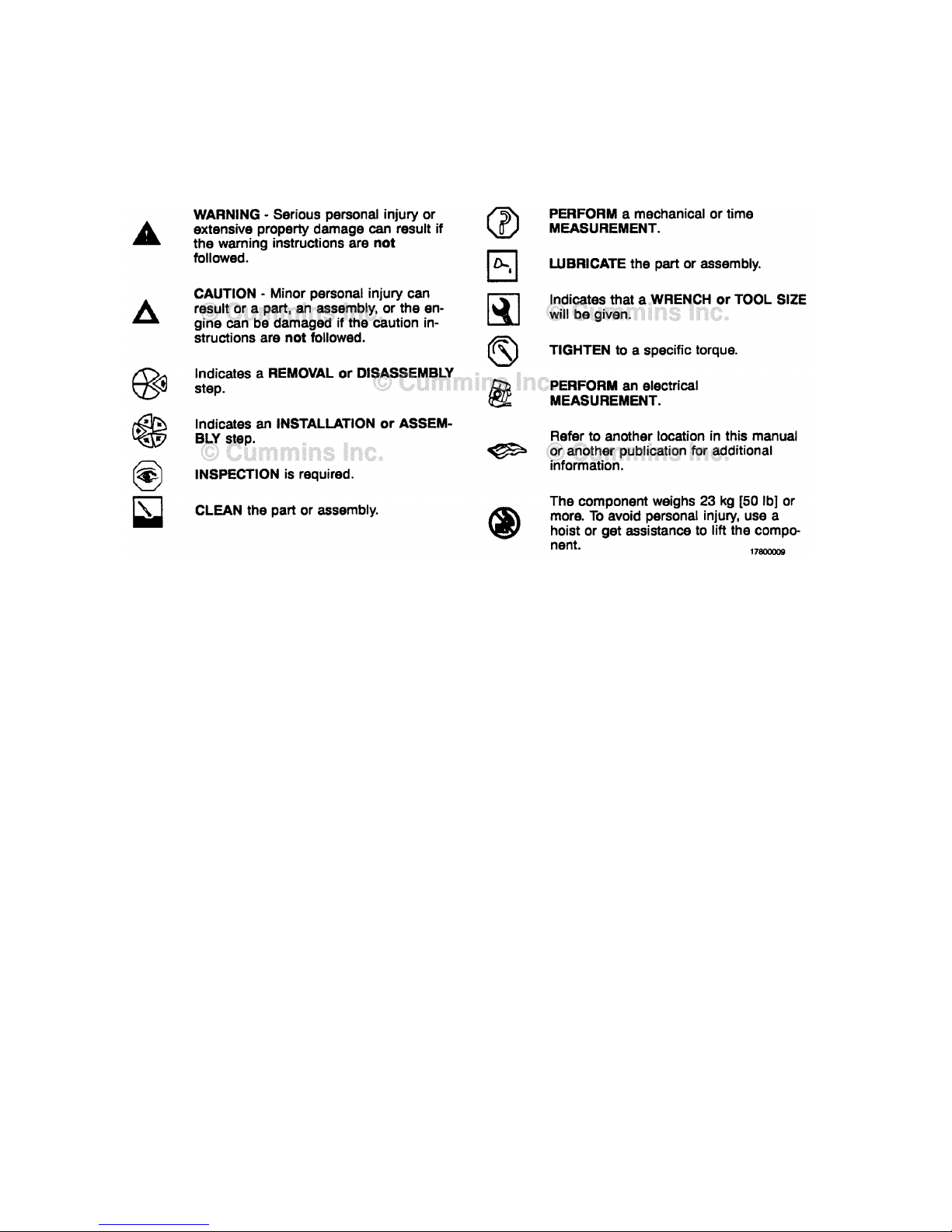
Some of the illustrations throughout this manual are
generic and will not look exactly like the engine or parts
used in your application. The illustrations can contain
symbols to indicate an action required and an acceptable
or not acceptable condition.
The illustrations are intended to show repair or
replacement procedures. The procedure will be the same
for all applications, although the illustration can differ.
Page 13

General Safety Instructions B3.9, B4.5, B5.9 Industrial
Page i-6 Section i - Introduction
General Safety Instructions
Important Safety Notice
WARNING
Improper practices, carelessness, or ignoring the warnings can cause burns, cuts, mutilation, asphyxiation or
other personal injury or death.
Read and understand all of the safety precautions and warnings before performing any repair. This list contains the
general safety precautions that must be followed to provide personal safety. Special safety precautions are included
in the procedures when they apply.
• Work in an area surrounding the product that is dry, well lit, ventilated, free from clutter, loose tools, parts, ignition
sources and hazardous substances. Be aware of hazardous conditions that can exist.
• Always wear protective glasses and protective shoes when working.
• Rotating parts can cause cuts, mutilation or strangulation.
• Do not wear loose-fitting or torn clothing. Remove all jewelry when working.
• Disconnect the battery (negative [-] cable first) and discharge any capacitors before beginning any repair work.
Disconnect the air starting motor if equipped to prevent accidental engine starting. Put a "Do Not Operate" tag in
the operator's compartment or on the controls.
• Use ONLY the proper engine barring techniques for manually rotating the engine. Do not attempt to rotate the
crankshaft by pulling or prying on the fan. This practice can cause serious personal injury, property damage, or
damage to the fan blade(s) causing premature fan failure.
• If an engine has been operating and the coolant is hot, allow the engine to cool before slowly loosening the filler
cap to relieve the pressure from the cooling system.
• Always use blocks or proper stands to support the product before performing any service work. Do not work on
anything that is supported ONLY by lifting jacks or a hoist.
• Relieve all pressure in the air, oil, fuel, and cooling systems before any lines, fittings, or related items are removed
or disconnected. Be alert for possible pressure when disconnecting any device from a system that utilizes
pressure. Do not check for pressure leaks with your hand. High pressure oil or fuel can cause personal injury.
• To reduce the possibility of suffocation and frostbite, wear protective clothing and ONLY disconnect liquid
refrigerant (Freon) lines in a well ventilated area. To protect the environment, liquid refrigerant systems must be
properly emptied and filled using equipment that prevents the release of refrigerant gas (fluorocarbons) into the
atmosphere. Federal law requires capturing and recycling refrigerant.
• To reduce the possibility of personal injury, use a hoist or get assistance when lifting components that weigh 23 kg
[50 lb] or more. Make sure all lifting devices such as chains, hooks, or slings are in good condition and are of the
correct capacity. Make sure hooks are positioned correctly. Always use a spreader bar when necessary. The lifting
hooks must not be side-loaded.
• Corrosion inhibitor, a component of SCA and lubricating oil, contains alkali. Do not get the substance in eyes.
Avoid prolonged or repeated contact with skin. Do not swallow internally. In case of contact, immediately wash
skin with soap and water. In case of contact, immediately flood eyes with large amounts of water for a minimum of
15 minutes. IMMEDIATELY CALL A PHYSICIAN. KEEP OUT OF REACH OF CHILDREN.
• Naptha and Methyl Ethyl Ketone (MEK) are flammable materials and must be used with caution. Follow the
manufacturer's instructions to provide complete safety when using these materials. KEEP OUT OF REACH OF
CHILDREN.
• To reduce the possibility of burns, be alert for hot parts on products that have just been turned off, exhaust gas
flow, and hot fluids in lines, tubes, and compartments.
• Always use tools that are in good condition. Make sure you understand how to use the tools before performing any
service work. Use ONLY genuine Cummins® or Cummins ReCon® replacement parts.
• Always use the same fastener part number (or equivalent) when replacing fasteners. Do not use a fastener of
lesser quality if replacements are necessary.
• When necessary, the removal and replacement of any guards covering rotating components, drives, and/or belts
should only be carried out be a trained technician. Before removing any guards the engine must be turned off and
any starting mechanisms must be isolated. All fasteners must be replaced on re-fitting the guards.
• Do not perform any repair when fatigued or after consuming alcohol or drugs that can impair your functioning.
Page 14

B3.9, B4.5, B5.9 Industrial General Safety Instructions
Section i - Introduction Page i-7
• Some state and federal agencies in the United States of America have determined that used engine oil can be
carcinogenic and can cause reproductive toxicity. Avoid inhalation of vapors, ingestion, and prolonged contact with
used engine oil.
• Do not connect the jumper starting or battery charging cables to any ignition or governor control wiring. This can
cause electrical damage to the ignition or governor.
• Always torque fasteners and fuel connections to the required specifications. Overtightening or undertightening can
allow leakage. This is critical to the natural gas and liquefied petroleum gas fuel and air systems.
• Always test for fuel leaks as instructed, as odorant can fade.
• Close the manual fuel valves prior to performing maintenance and repairs, and when storing the vehicle inside.
• Coolant is toxic. If not reused, dispose of in accordance with local environmental regulations.
• The catalyst reagent contains urea. Do not get the substance in your eyes. In case of contact, immediately flood
eyes with large amounts of water for a minimum of 15 minutes. Avoid prolonged contact with skin. In case of
contact, immediately wash skin with soap and water. Do not swallow internally. In the event the catalyst reagent is
ingested, contact a physician immediately.
• The catalyst substrate contains Vanadium Pentoxide. Vanadium Pentoxide has been determined by the State of
California to cause cancer. Always wear protective gloves and eye protection when handling the catalyst assembly.
Do not get the catalyst material in your eyes. In Case of contact, immediately flood eyes with large amounts of
water for a minimum of 15 minutes. Avoid prolonged contact with skin. In case of contact, immediately wash skin
with soap and water.
• The Catalyst substrate contains Vanadium Pentoxide. Vanadium Pentoxide has been determined by the State of
California to cause cancer. In the event the catalyst is being replaced, dispose of in accordance with local
regulations.
• California Proposition 65 Warning - Diesel engine exhaust and some of its constituents are known to the State of
California to cause cancer, birth defects, and other reproductive harm.
Page 15

General Repair Instructions B3.9, B4.5, B5.9 Industrial
Page i-8 Section i - Introduction
General Repair Instructions
General Information
This engine or system incorporates the latest technology at the time it was manufactured; yet, it is designed to be
repaired using normal repair practices performed to quality standards.
WARNING
Cummins Inc. does not recommend or authorize any modifications or repairs to components except for those
detailed in Cummins Service Information. In particular, unauthorized repair to safety-related components can
cause personal injury or death. Below is a partial listing of components classified as safety-related:
1 Air Compressor
2 Air Controls
3 Air Shutoff Assemblies
4 Balance Weights
5 Cooling Fan
6 Fan Hub Assembly
7 Fan Mounting Bracket(s)
8 Fan Mounting Capscrews
9 Fan Hub Spindle
10 Flywheel
11 Flywheel Crankshaft Adapter
12 Flywheel Mounting Capscrews
13 Fuel Shutoff Assemblies
14 Fuel Supply Tubes
15 Lifting Brackets
16 Throttle Controls
17 Turbocharger Compressor Casing
18 Turbocharger Oil Drain Line(s)
19 Turbocharger Oil Supply Line(s)
20 Turbocharger Turbine Casing
21 Vibration Damper Mounting Capscrews
22 Manual Service Disconnect
23 High Voltage Interlock Loop
24 High Voltage Connectors/Connections and Harnesses
25 High Voltage Battery System
26 Power Inverter
27 Generator Motor
28 Clutch Pressure Plate
• Follow all safety instructions noted in the procedures
• Follow the manufacturer's recommendations for cleaning solvents and other substances used during repairs. Some
solvents have been identified by government agencies as toxic or carcinogenic. Avoid excessive breathing,
ingestion and contact with such substances. Always use good safety practices with tools and equipment
• Provide a clean environment and follow the cleaning instructions specified in the procedures
• The engine or system and its components must be kept clean during any repair. Contamination of the engine,
system or components will cause premature wear.
• All components must be kept clean during any repair. Contamination of the components will cause premature
wear.
Page 16

B3.9, B4.5, B5.9 Industrial General Repair Instructions
Section i - Introduction Page i-9
• Perform the inspections specified in the procedures
• Replace all components or assemblies which are damaged or worn beyond the specifications
• Use genuine Cummins new or ReCon® service parts and assemblies
- The assembly instructions have been written to use again as many components and assemblies as possible.
When it is necessary to replace a component or assembly, the procedure is based on the use of new Cummins or
Cummins ReCon® components. All of the repair services described in this manual are available from all Cummins
Distributors and most Dealer locations.
• Follow the specified disassembly and assembly procedures to reduce the possibility of damage to the components
Complete rebuild instructions are available in the service manual which can be ordered or purchased from a Cummins
Authorized Repair Location. Refer to Section L — Service Literature for ordering instructions.
Welding on a Vehicle with an Electronic Controlled Fuel System
CAUTION
Disconnect both the positive (+) and negative (-) battery cables from the low voltage battery before welding on
the vehicle. Attach the welder ground cable no more than 0.61 meters [2 feet] from the part being welded. Do
not connect the ground clamp of the welder to any of the sensors, wiring harness, electronic control units or
the components. Direct welding of any electronic components must not be attempted. Sensors, wiring
harness, and electronic control unit should be removed if nearby welding will expose these components to
temperatures beyond normal operation. Additionally, all electronic control unit connectors must be
disconnected
Page 17

General Cleaning Instructions B3.9, B4.5, B5.9 Industrial
Page i-10 Section i - Introduction
General Cleaning Instructions
Definition of Clean
Parts must be free of debris that can contaminate any engine system. This does not necessarily mean they have to
appear as new.
Sanding gasket surfaces until the factory machining marks are disturbed adds no value and is often harmful to forming
a seal. It is important to maintain surface finish and flatness tolerances to form a quality sealing surface. Gaskets are
designed to fill small voids in the specified surface finish.
Sanding gasket surfaces where edge-molded gaskets are used is most often unnecessary. Edge-molded gaskets are
those metal carriers with sealing material bonded to the edges of the gasket to seal while the metal portion forms a
metal to metal joint for stability. Any of the small amounts of sealing material that can stick to the parts are better
removed with a blunt-edged scraper on the spots rather than spending time polishing the whole surface with an air
sander or disc.
For those gaskets that do not have the edge molding, nearly all have a material that contains release agents to
prevent sticking. Certainly this is not to say that some gaskets are not difficult to remove because the gasket has
been in place a long time, has been overheated or the purpose of the release agent has been defeated by the
application of some sealant. The object however is just to remove the gasket without damaging the surfaces of the
mating parts without contaminating the engine (don't let the little bits fall where they can not be removed).
Bead blasting piston crowns until the dark stain is removed is unnecessary. All that is required is to remove the carbon
build-up above the top ring and in the ring grooves. There is more information on bead blasting and piston cleaning
later in this document.
Cummins Inc. does not recommend sanding or grinding the carbon ring at the top of cylinder liners until clean metal is
visible. The liner will be ruined and any signs of a problem at the top ring reversal point (like a dust-out) will be
destroyed. It is necessary to remove the carbon ring to provide for easier removal of the piston assembly. A medium
bristle, high quality, steel wire wheel that is rated above the rpm of the power tool being used will be just as quick and
there will be less damage. Yes, one must look carefully for broken wires after the piston is removed but the wires are
more visible and can be attracted by a magnet.
Oil on parts that have been removed from the engine will attract dirt in the air. The dirt will adhere to the oil. If possible,
leave the old oil on the part until it is ready to be cleaned, inspected and installed, and then clean it off along with any
attracted dirt. If the part is cleaned then left exposed it can have to be cleaned again before installation. Make sure
parts are lubricated with clean oil before installation. They do not need to be oiled all over but do need oil between
moving parts (or a good lube system priming process conducted before cranking the engine).
Bead blasting parts to remove exterior paint is also usually unnecessary. The part will most likely be painted again so
all that needs happen is remove any loose paint.
Abrasive Pads and Abrasive Paper
The keyword here is "abrasive". There is no part of an engine designed to withstand abrasion. That is they are all
supposed to lock together or slide across each other. Abrasives and dirt particles will degrade both functions.
WARNING
Abrasive material must be kept out of or removed from oil passages and parts wear points. Abrasive material
in oil passages can cause bearing and bushing failures that can progress to major component damage
beyond reuse. This is particularly true of main and rod bearings.
Cummins Inc. does not recommend the use of emery cloth or sand paper on any part of an assembled engine or
component including but not limited to removing the carbon ridge from cylinder liners or to clean block decks or
counterbores.
Great care must be taken when using abrasive products to clean engine parts, particularly on partially assembled
engines. Abrasive cleaning products come in many forms and sizes. All of them contain aluminum oxide particles,
silicon carbide, or sand or some other similar hard material. These particles are harder than most of the parts in the
engine. Since they are harder, if they are pressed against softer material they will either damage the material or
become embedded in it. These materials fall off the holding media as the product is used. If the products are used with
power equipment the particles are thrown about the engine. If the particles fall between two moving parts, damage to
the moving parts is likely.
If particles that are smaller than the clearance between the parts while they are at rest (engine stopped), but larger
than the running clearance then damage will occur when the parts move relative to each other (engine started). While
the engine is running and there is oil pressure, particles that are smaller than the bearing clearance are likely to pass
between the parts without damage and be trapped in the oil filter. However, particles larger than the bearing clearance
will remove material from one part and can become embedded in one of the parts. Once embedded in one part it will
Page 18

B3.9, B4.5, B5.9 Industrial General Cleaning Instructions
Section i - Introduction Page i-11
abrade the other part until contact is no longer being made between the two parts. If the damage sufficiently degrades
the oil film, the two parts will come into contact resulting in early wear-out or failure from lack of effective lubrication.
Abrasive particles can fly about during cleaning it is very important to block these particles from entering the engine as
much as possible. This is particularly true of lubricating oil ports and oil drilling holes, especially those located
downstream of the lubricating oil filters. Plug the holes instead of trying to blow the abrasive particles and debris with
compressed air because the debris is often simply blown further into the oil drilling.
All old gasket material must be removed from the parts gasket surfaces. However, it is not necessary to clean and
polish the gasket surface until the machining marks are erased. Excessive sanding or buffing can damage the gasket
surface. Many newer gaskets are of the edge molded type (a steel carrier with a sealing member bonded to the steel).
What little sealing material that can adhere is best removed with a blunt-edged scraper or putty knife. Cleaning gasket
surfaces where an edge-molded gasket is used with abrasive pads or paper is usually a waste of time.
WARNING
Excessive sanding or grinding the carbon ring from the top of the cylinder liners can damage the liner beyond
reuse. The surface finish will be damaged and abrasive particles can be forced into the liner material which
can cause early cylinder wear-out or piston ring failures.
Tape off or plug all openings to any component interior before using abrasive pads or wire brushes. If really necessary
because of time to use a power tool with abrasive pads, tape the oil drillings closed or use plug and clean as much of
the surface as possible with the tool but clean around the oil hole/opening by hand so as to prevent contamination of
the drilling. Then remove the tape or plug and clean the remaining area carefully and without the tool. DO NOT use
compressed air to blow the debris out of oil drilling on an assembled engine! More likely than not, the debris can be
blown further into the drilling. Using compressed air is fine if both ends of the drilling are open but that is rarely the
case when dealing with an assembled engine.
Gasket Surfaces
The object of cleaning gasket surfaces is to remove any gasket material, not refinish the gasket surface of the part.
Cummins Inc. does not recommend any specific brand of liquid gasket remover. If a liquid gasket remover is used,
check the directions to make sure the material being cleaned will not be harmed.
Air powered gasket scrapers can save time but care must be taken to not damage the surface. The angled part of the
scraper must be against the gasket surface to prevent the blade from digging into the surface. Using air powered
gasket scrapers on parts made of soft materials takes skill and care to prevent damage.
Do not scrape or brush across the gasket surface if at all possible.
Solvent and Acid Cleaning
Several solvent and acid-type cleaners can be used to clean the disassembled engine parts (other than pistons. See
Below). Experience has shown that the best results can be obtained using a cleaner that can be heated to 90° to 95°
Celsius (180° to 200° Fahrenheit). Kerosene emulsion based cleaners have different temperature specifications, see
below. A cleaning tank that provides a constant mixing and filtering of the cleaning solution will give the best results.
Cummins Inc. does not recommend any specific cleaners. Always follow the cleaner manufacturer's instructions.
Remove all the gasket material, o-rings, and the deposits of sludge, carbon, etc., with a wire brush or scraper before
putting the parts in a cleaning tank. Be careful not to damage any gasket surfaces. When possible, steam clean the
parts before putting them in the cleaning tank.
WARNING
When using solvents, acids, or alkaline materials for cleaning, follow the manufacturers recommendations for
use. Wear goggles and protective clothing to reduce the possibility of personal injury.
Experience has shown that kerosene emulsion based cleaners perform the best to clean pistons. These cleaners
should not be heated to temperature in excess of 77°C (170°F). The solution begins to break down at temperatures in
excess of 82°C (180°F) and will be less effective.
Do not use solutions composed mainly of chlorinated hydrocarbons with cresols, phenols and/or cresylic components.
They often do not do a good job of removing deposits from the ring groove and are costly to dispose of properly.
Solutions with a pH above approximately 9.5 will cause aluminum to turn black; therefore do not use high alkaline
solutions.
Chemicals with a pH above 7.0 are considered alkaline and those below 7.0 are acidic. As you move further away
from the neutral 7.0, the chemicals become highly alkaline or highly acidic.
Remove all the gasket material, o-rings, and the deposits of sludge, carbon, etc., with a wire brush or scraper before
putting the parts in a cleaning tank. Be careful to not damage any gasket surfaces. When possible use hot high
Page 19

General Cleaning Instructions B3.9, B4.5, B5.9 Industrial
Page i-12 Section i - Introduction
pressure water or steam clean the parts before putting them in the cleaning tank. Removing the heaviest dirt before
placing in the tank will allow the cleaner to work more effectively and the cleaning agent will last longer.
Rinse all the parts in hot water after cleaning. Dry completely with compressed air. Blow the rinse water from all the
capscrew holes and the oil drillings.
If the parts are not to be used immediately after cleaning, dip them in a suitable rust proofing compound. The rust
proofing compound must be removed from the parts before assembly or installation on the engine.
Steam Cleaning
Steam cleaning can be used to remove all types of dirt that can contaminate the cleaning tank. It is a good method for
cleaning the oil drillings and coolant passages
WARNING
When using a steam cleaner, wear safety glasses or a face shield, as well as protective clothing. Hot steam
can cause serious personal injury.
Do not steam clean the following components:
• Electrical Components
• Wiring Harnesses
• Belts and Hoses
• Bearings (ball or taper roller)
• Electronic Control Module (ECM)
• ECM Connectors
• Capacitive Coil Driver Module (CCD)
• Ignition Coils and Leads
• NOx Sensor
• Fuel Control Valve
• Throttle Driver and Actuator.
Plastic Bead Cleaning
Cummins Inc. does not recommend the use of glass bead blast or walnut shell media on any engine part. Cummins
Inc. recommends using only plastic bead media, Part Number 3822735 or equivalent on any engine part. Never use
sand as a blast media to clean engine parts. Glass and walnut shell media when not used to the media
manufacturer's recommendations can cause excess dust and can embed in engine parts that can result in premature
failure of components through abrasive wear.
Plastic bead cleaning can be used on many engine components to remove carbon deposits. The cleaning process is
controlled by the use of plastic beads, the operating pressure and cleaning time.
CAUTION
Do not use bead blasting cleaning methods on aluminum pistons skirts or the pin bores in any piston, piston
skirt or piston crown. Small particles of the media will embed in the aluminum or other soft metal and result in
premature wear of the cylinder liner, piston rings, pins and pin bores. Valves, turbocharger shafts, etc., can
also be damaged. Follow the cleaning directions listed in the procedures.
CAUTION
Do not contaminate wash tanks and tank type solvent cleaners with the foreign material and plastic beads.
Remove the foreign material and plastic beads with compressed air, hot high pressure water or steam before
placing them in tanks or cleaners. The foreign material and plastic beads can contaminate the tank and any
other engine parts cleaned in the tank. Contaminated parts may cause failures from abrasive wear.
Plastic bead blasting media, Part Number 3822735, can be used to clean all piston ring grooves. Do not sure any
bead blasting media on piston pin bores or aluminum skirts.
Follow the equipment manufacturer's cleaning instructions. Make sure to adjust the air pressure in the blasting
machine to the bead manufacturer's recommendations. Turning up the pressure can move material on the part and
cause the plastic bead media to wear out more quickly. The following guidelines can be used to adapt to
manufacturer's instructions:
1 Bead size: U.S. size Number 16 — 20 for piston cleaning with plastic bead media, Part Number 3822735
Page 20

B3.9, B4.5, B5.9 Industrial General Cleaning Instructions
Section i - Introduction Page i-13
2 Operating Pressure — 270 kPa (40 psi) for piston cleaning. Pressure should not cause beads to break.
3 Steam clean or wash the parts with solvent to remove all of the foreign material and plastic beads after cleaning.
Rinse with hot water. Dry with compressed air.
CAUTION
The bead blasting operation must not disturb the metal surface. If the metal surface is disturbed the engine
can be damaged due to increased parts clearance or inadequate surface finish on parts that move against
other parts.
When cleaning pistons, it is not necessary to remove all the dark stain from the piston. All that is necessary is to
remove the carbon on the rim and in the ring grooves. This is best done by directing the blast across the part as
opposed to straight at the part. If the machining marks are disturbed by the blasting process, then the pressure is too
high or the blast is being held on one spot too long. The blast operation must not disturb the metal surface.
Walnut shell bead blast material is sometimes used to clean ferrous metals (iron and steel). Walnut shell blasting
produces a great amount of dust particularly when the pressure if the air pressure on the blasting machine is
increased above media manufacturer's recommendation. Cummins Inc. recommends not using walnut shell media to
clean engine parts due to the risk media embedment and subsequent contamination of the engine.
Cummins Inc. now recommends glass bead media NOT used to clean any engine parts. Glass media is too easily
embedded into the material particularly in soft materials and when air pressures greater than media manufacturer's
recommend are used. The glass is an abrasive so when it is in a moving part, that part is abrading all the parts in
contact with it. When higher pressures are used the media is broken and forms a dust of a very small size that floats
easily in the air. This dust is very hard to control in the shop, particularly if only compressed air (and not hot water) is
used to blow the media after it is removed from the blasting cabinet (blowing the part off inside the cabinet may
remove large accumulations but never removes all the media).
Bead blasting is best used on stubborn dirt/carbon build-up that has not been removed by first steam/higher pressure
washing then washing in a heated wash tank. This is particularly true of pistons. Steam and soak the pistons first then
use the plastic bead method to safely remove the carbon remaining in the grooves (instead of running the risk of
damaging the surface finish of the groove with a wire wheel or end of a broken piston ring. Make sure the parts are dry
and oil free before bead blasting to prevent clogging the return on the blasting machine.
Always direct the bead blaster nozzle "across" rather than directly at the part. This allows the bead to get under the
unwanted material. Keep the nozzle moving rather than hold on one place. Keeping the nozzle directed at one-place
too long causes the metal to heat up and be moved around. Remember that the spray is not just hitting the dirt or
carbon. If the machining marks on the piston groove or rim have been disturbed then there has not been enough
movement of the nozzle and/or the air pressure is too high.
Never bead blast valve stems. Tape or use a sleeve to protect the stems during bead blasting. Direct the nozzle
across the seat surface and radius rather than straight at them. The object is to remove any carbon build up and
continuing to blast to remove the stain is a waste of time.
Fuel System
When servicing any fuel system components, which can be exposed to potential contaminants, prior to disassembly,
clean the fittings, mounting hardware, and the area around the component to be removed. If the surrounding areas are
not cleaned, dirt or contaminants can be introduced into the fuel system.
The internal drillings of some injectors are extremely small and susceptible to plugging from contamination. Some fuel
injection systems can operate at very high pressures. High pressure fuel can convert simple particles of dirt and rust
into a highly abrasive contaminant that can damage the high pressure pumping components and fuel injectors.
Electrical contact cleaner can be used if steam cleaning tools are not available. Use electrical contact cleaner rather
than compressed air, to wash dirt and debris away from fuel system fittings. Diesel fuel on exposed fuel system parts
attracts airborne contaminants.
Choose lint free towels for fuel system work.
Cap and plug fuel lines, fittings, and ports whenever the fuel system is opened. Rust, dirt, and paint can enter the fuel
system whenever a fuel line or other component is loosened or removed from the engine. In many instances, a good
practice is to loosen a line or fitting to break the rust and paint loose, and then clean off the loosened material.
When removing fuel lines or fittings from a new or newly-painted engine, make sure to remove loose paint flakes/chips
that can be created when a wrench contacts painted line nuts or fittings, or when quick disconnect fittings are
removed.
Fuel filters are rated in microns. The word micron is the abbreviation for a micrometer, or one millionth of a meter. The
micron rating is the size of the smallest particles that will be captured by the filter media. As a reference, a human hair
Page 21

General Cleaning Instructions B3.9, B4.5, B5.9 Industrial
Page i-14 Section i - Introduction
is 76 microns [0.003 in] in diameter. One micron measures 0.001 mm [0.00004 in.]. The contaminants being filtered
out are smaller than can be seen with the human eye, a magnifying glass, or a low powered microscope.
The tools used for fuel system troubleshooting and repair are to be cleaned regularly to avoid contamination. Like fuel
system parts, tools that are coated with oil or fuel attract airborne contaminants. Remember the following points
regarding your fuel system tools:
• Fuel system tools are to be kept as clean as possible.
• Clean and dry the tools before returning them to the tool box.
• If possible, store fuel system tools in sealed containers.
• Make sure fuel system tools are clean before use.
Page 22

B3.9, B4.5, B5.9 Industrial Acronyms and Abbreviations
Section i - Introduction Page i-15
Acronyms and Abbreviations
General Information
The following list contains some of the acronyms and abbreviations used in this manual.
ANSI American National Standards Institute
API American Petroleum Institute
ASTM American Society of Testing and Materials
ATDC After Top Dead Center
BTU British Thermal Unit
BTDC Before Top Dead Center
°C Celsius
CAN Controller Area Network
CO Carbon Monoxide
CCA Cold Cranking Amperes
CARB California Air Resources Board
C.I.B. Customer Interface Box
C.I.D. Cubic Inch Displacement
CNG Compressed Natural Gas
CPL Control Parts List
cSt Centistokes
DEF Diesel Exhaust Fluid
DOC Diesel Oxidation Catalyst
DPF Diesel Particulate Filter
ECM Engine Control Module
EFC Electronic Fuel Control
EGR Exhaust Gas Recirculation
EPA Environmental Protection Agency
°F Fahrenheit
ft-lb Foot-Pound Force
FMI Failure Mode Indentifier
GVW Gross Vehicle Weight
Hg Mercury
hp Horsepower
H2O Water
inHg Inches of Mercury
in H20 Inches of Water
ICM Ignition Control Module
IEC International Electrotechnical Commission
km/l Kilometers per Liter
kPa Kilopascal
LNG Liquid Natural Gas
LPG Liquified Petroleum Gas
LTA Low Temperature Aftercooling
MCRS Modular Common Rail System
MIL Malfunction Indicator Lamp
MPa Megapascal
mph Miles Per Hour
mpq Miles Per Quart
N•m Newton-meter
Page 23

Acronyms and Abbreviations B3.9, B4.5, B5.9 Industrial
Page i-16 Section i - Introduction
NOx Mono-Nitrogen Oxides
NG Natural Gas
O2 Oxygen
OBD On-Board Diagnostics
OEM Original Equipment Manufacturer
OSHA Occupational Safety and Health Administration
PID Parameter Identification Descriptions
ppm Parts Per Million
psi Pounds Per Square Inch
PTO Power Takeoff
REPTO Rear Power Take Off
RGT Rear Gear Train
rpm Revolutions Per Minute
SAE Society of Automotive Engineers
SCA Supplemental Coolant Additive
SCR Selective Catalytic Reduction
STC Step Timing Control
SID Subsystem Identification Descriptions
TDC Top Dead Center
VDC Volts of Direct Current
VGT Variable Geometry Turbocharger
VS Variable Speed
VSS Vehicle Speed Sensor
Page 24

B3.9, B4.5, B5.9 Industrial
Section E - Engine and System Identification Page E-a
Section E - Engine and System Identification
Section Contents
Page
Cummins® Service Engine Model Product Identification ....................................................................................E-25
General Information..................................................................................................................................................E-25
Engine Diagrams ........................................................................................................................................................E-4
Engine Views..............................................................................................................................................................E-4
Engine Identification ..................................................................................................................................................E-1
Cummins® Engine Nomenclature..............................................................................................................................E-2
Engine Dataplate........................................................................................................................................................E-1
B3.9, B5.9, and B4.5 Engines.................................................................................................................................E-1
B4.5 RGT Engines..................................................................................................................................................E-1
Fuel Injection Pump Dataplate...................................................................................................................................E-3
Bosch® Rotary........................................................................................................................................................E-3
Delphi Rotary...........................................................................................................................................................E-3
Page 25

B3.9, B4.5, B5.9 Industrial
Page E-b Section E - Engine and System Identification
This Page Left Intentionally Blank
Page 26
B3.9, B4.5, B5.9 Industrial Engine Identification
Section E - Engine and System Identification Page E-1
Engine Identification
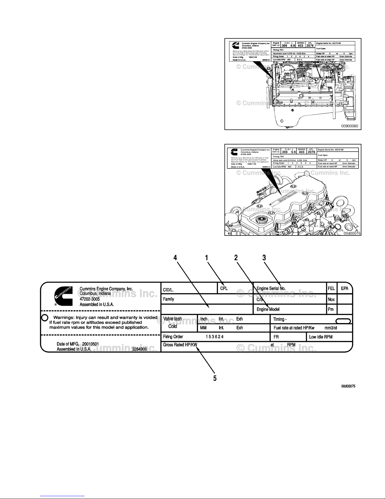
Engine Dataplate
B3.9, B5.9, and B4.5 Engines
The engine dataplate shows specific facts about your
engine. The engine serial number and Control Parts List
provide information for ordering parts and for service. The
engine dataplate must not be changed unless approved
by Cummins Inc.
B4.5 RGT Engines
The engine dataplate shows specific facts about your
engine. The engine serial number and Control Parts List
provide information for ordering parts and for service. The
engine dataplate must not be changed unless approved
by Cummins Inc.
Have the following engine data available when communicating with a Cummins Authorized Repair Location. The
information on the dataplate is mandatory when sourcing service parts.
1. Control parts list (CPL)
2. Model
3. Engine serial number
4. Emissions certification
5. Horsepower and rpm rating.
Page 27
Engine Identification B3.9, B4.5, B5.9 Industrial
Page E-2 Section E - Engine and System Identification
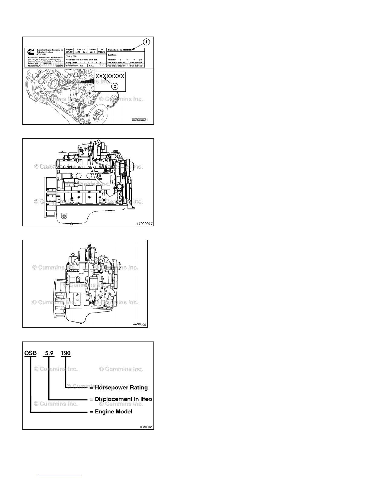
NOTE: If the engine dataplate (1) is not readable, the
engine serial number (2) can be identified on the engine
block above the oil cooler.
Cummins® Engine Nomenclature
B5.9
The model name provides the following engine data:
B = Engine series
5.9 = Displacement in liters.
B3.9
The model name provides the following engine data:
B = Engine series
3.9 = Displacement in liters.
The Cummins engine nomenclature provides the data as
illustrated in the graphic.
Page 28
B3.9, B4.5, B5.9 Industrial Engine Identification
Section E - Engine and System Identification Page E-3
The model name for engines in industrial applications
provides the data shown below For example:
4BTAA-3.9
4 = Number of cylinders
B = Engine series
T = Turbocharged
AA = Charge air cooled
3.9 = Displacement in liters.
NOTE: The suffix RGT refers to “Rear Gear Train”
engines.
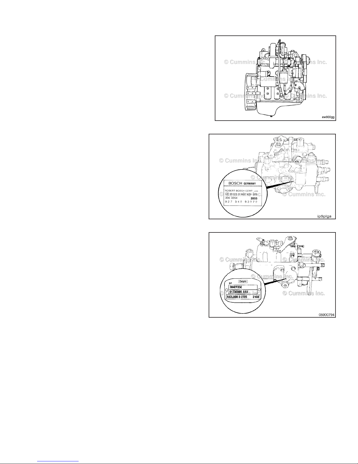
Fuel Injection Pump Dataplate
Bosch® Rotary
The injection pump dataplate for the Bosch® VE pump is
located on the side of the injection pump. The dataplate
provides information for fuel pump calibration.
Delphi Rotary
The injection pump dataplate for the Delphi DP pump is
located on the side of the injection pump. The dataplate
provides information for fuel pump calibration.
Page 29

Engine Diagrams B3.9, B4.5, B5.9 Industrial
Page E-4 Section E - Engine and System Identification
Engine Diagrams
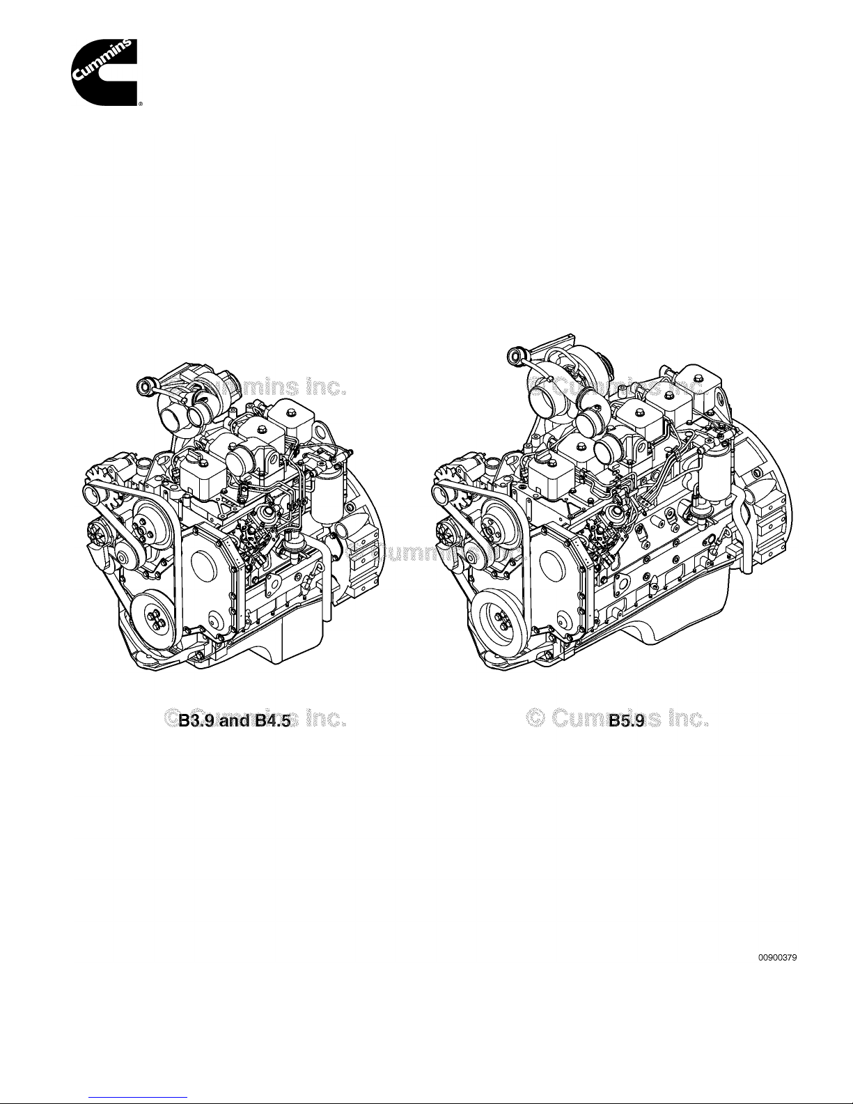
Engine Views
The following illustrations show the locations of the major external engine components, filters, and other service and
maintenance points. Some external components will be at different locations for different engine models.
NOTE: The illustrations are only a reference to show a typical engine.
Page 30
B3.9, B4.5, B5.9 Industrial Engine Diagrams
Section E - Engine and System Identification Page E-5
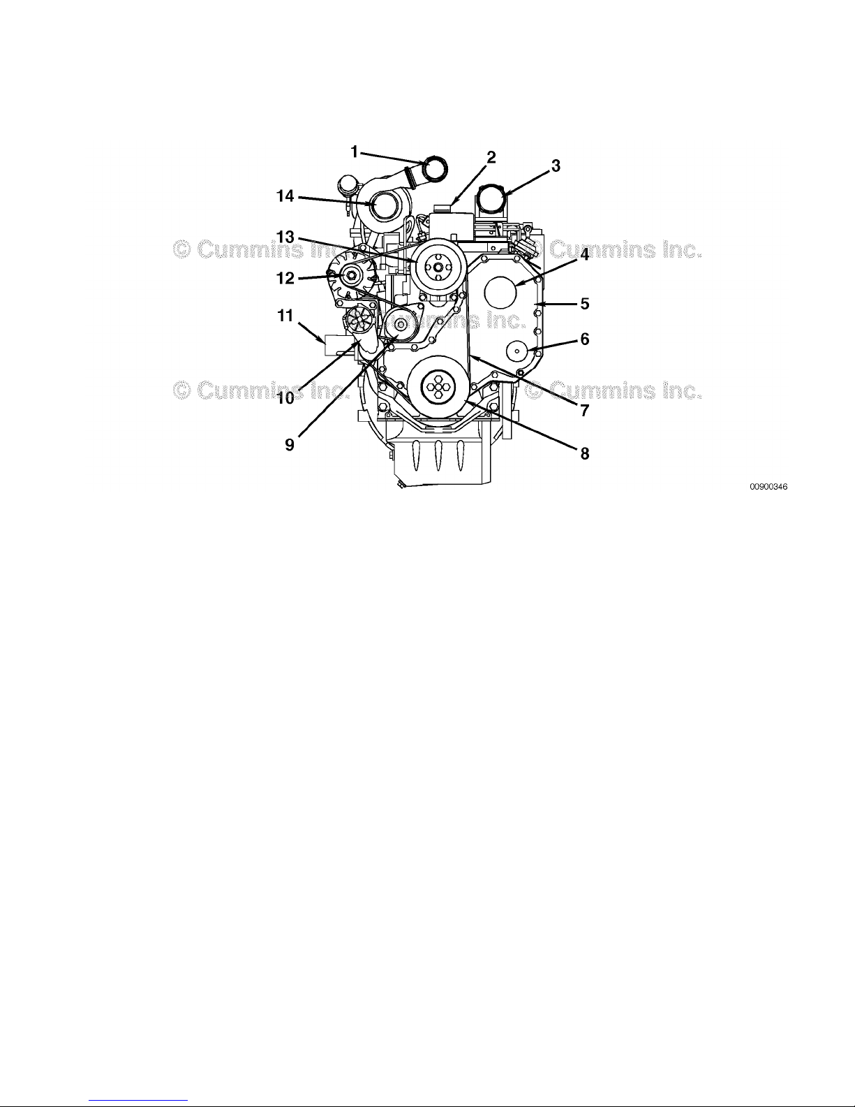
Engine Views
Engine Diagrams
1. Turbocharger air outlet
2. Lubricating oil fill
3. Engine air inlet
4. Fuel pump drive cover
5. Front gear cover
6. Accessory drive cover (optional)
7. Fan drive belt
8. Front Pulley
9. Water pump
10. Automatic belt tensioner
11. Water inlet
12. Alternator
13. Fan pulley
14. Turbocharger air inlet.
Front View - B3.9 Industrial
Page 31

Engine Diagrams B3.9, B4.5, B5.9 Industrial
Page E-6 Section E - Engine and System Identification
Engine Views
Engine Diagrams
1. Engine air inlet
2. Fuel filter/water separator
3. Fuel inlet connection
4. Magnetic pickup location (3/4-16 UNF)
5. Fuel lift pump
6. Crankcase breather tube
7. Lubricating oil dipstick
8. Fuel drain connection
9. Front engine mounting bracket
10. Engine dataplate
11. High pressure fuel lines
12. Fuel injection pump
13. Intake air preheater (optional).
Left Side View - B3.9 Industrial
Page 32

B3.9, B4.5, B5.9 Industrial Engine Diagrams
Section E - Engine and System Identification Page E-7
Engine Views
Engine Diagrams
1. Rear engine lifting bracket
2. Turbocharger exhaust outlet
3. Flexplate mounting holes
4. Flywheel housing
5. Flywheel/flexplate.
Rear View - B3.9 Industrial
Page 33

Engine Diagrams B3.9, B4.5, B5.9 Industrial
Page E-8 Section E - Engine and System Identification
Engine Views
Engine Diagrams
Right Side View - B3.9 Industrial
1. Fuel injection nozzles
2. Turbocharger wastegate actuator
3. Lubricating oil fill
4. Front engine lifting bracket
5. Water outlet
6. Lubricating oil filter
7. Water inlet
8. Lubricating oil cooler
9. Lubricating oil drain
10. Provision for lubricating oil immersion heater
11. Starter motor and solenoid
12. Provision for coolant heater.
Page 34

B3.9, B4.5, B5.9 Industrial Engine Diagrams
Section E - Engine and System Identification Page E-9
Engine Views
Engine Diagrams
1. Water outlet
2. Turbocharger
3. Exhaust manifold
4. Magnetic pickup location (3/4-16 UNF)
5. Engine air inlet.
Top View - B3.9 Industrial
Page 35

Engine Diagrams B3.9, B4.5, B5.9 Industrial
Page E-10 Section E - Engine and System Identification
Engine Views
Engine Diagrams
1. Turbocharger air outlet
2. Lubricating oil fill
3. Engine air inlet
4. Fuel pump drive cover
5. Front gear cover
6. Accessory drive cover (optional)
7. Fan drive belt
8. Front Pulley
9. Water pump
10. Automatic belt tensioner
11. Water inlet
12. Alternator
13. Fan pulley
14. Turbocharger air inlet.
Front View - B4.5 Industrial
Page 36

B3.9, B4.5, B5.9 Industrial Engine Diagrams
Section E - Engine and System Identification Page E-11
Engine Views
Engine Diagrams
1. Engine air inlet
2. Fuel filter/water separator
3. Fuel inlet connection
4. Magnetic pickup location (3/4-16 UNF)
5. Fuel lift pump
6. Crankcase breather tube
7. Lubricating oil dipstick
8. Fuel drain connection
9. Front engine mounting bracket
10. Engine dataplate
11. High pressure fuel lines
12. Fuel injection pump
13. Intake air preheater (optional).
Left Side View - B4.5 Industrial
Page 37

Engine Diagrams B3.9, B4.5, B5.9 Industrial
Page E-12 Section E - Engine and System Identification
Engine Views
Engine Diagrams
1. Rear engine lifting bracket
2. Turbocharger exhaust outlet
3. Flexplate mounting holes
4. Flywheel housing
5. Flywheel/flexplate.
Rear View - B4.5 Industrial
Page 38

B3.9, B4.5, B5.9 Industrial Engine Diagrams
Section E - Engine and System Identification Page E-13
Engine Views
Engine Diagrams
Right Side View - B4.5 Industrial
1. Fuel injection nozzles
2. Turbocharger wastegate actuator
3. Lubricating oil fill
4. Front engine lifting bracket
5. Water outlet
6. Lubricating oil filter
7. Water inlet
8. Lubricating oil cooler
9. Lubricating oil drain
10. Provision for lubricating oil immersion heater
11. Starter motor and solenoid
12. Provision for coolant heater.
Page 39

Engine Diagrams B3.9, B4.5, B5.9 Industrial
Page E-14 Section E - Engine and System Identification
Engine Views
Engine Diagrams
1. Water outlet
2. Turbocharger
3. Exhaust manifold
4. Magnetic pickup location (3/4-16 UNF)
5. Engine air inlet.
Top View - B4.5 Industrial
Page 40

B3.9, B4.5, B5.9 Industrial Engine Diagrams
Section E - Engine and System Identification Page E-15
Engine Views
Engine Diagrams
1. Engine air inlet
2. Lubricating oil dipstick
3. Fan drive belt
4. Front pulley
5. Water pump
6. Automatic belt tensioner
7. Alternator
8. Fan pulley
9. Lubricating oil fill.
Front View - B4.5 RGT
Page 41

Engine Diagrams B3.9, B4.5, B5.9 Industrial
Page E-16 Section E - Engine and System Identification
Engine Views
Engine Diagrams
1. Lubricating oil dipstick
2. High pressure fuel lines
3. Rear engine mounting bracket
4. Fuel return line and fuel drain connection
5. Inlet fuel filter
6. Crankcase breather tube
7. Fuel injection pump
8. Engine dataplate
9. Provision for lubricating oil immersion heater
10. Fuel lift pump
11. Magnetic pickup location (3/4-16 UNF)
12. Fuel filter/water separator
13. Intake air preheater (optional)
14. Engine air inlet.
Left Side View - B4.5 RGT
Page 42

B3.9, B4.5, B5.9 Industrial Engine Diagrams
Section E - Engine and System Identification Page E-17
Engine Views
Engine Diagrams
1. Rear engine lifting bracket
2. Fuel return and fuel drain connection
3. Inline fuel filter
4. Fuel Inlet connection
5. Exhaust outlet
6. Flexplate mounting holes
7. Flywheel/flexplate
8. Flywheel housing
9. Rear gear train housing
10. Crankcase breather tube.
Rear View - B4.5 RGT
Page 43

Engine Diagrams B3.9, B4.5, B5.9 Industrial
Page E-18 Section E - Engine and System Identification
Engine Views
Engine Diagrams
1. Lubricating oil fill
2. Front engine lifting bracket
3. Water outlet
4. Lubricating oil filter
5. Water inlet
6. Lubricating oil cooler
7. Lubricating oil drain
8. Starter motor and solenoid
9. Provision for coolant heater.
Right Side View - B4.5 RGT
Page 44

B3.9, B4.5, B5.9 Industrial Engine Diagrams
Section E - Engine and System Identification Page E-19
Engine Views
Engine Diagrams
1. Exhaust manifold
2. Engine air inlet
3. Magnetic pickup location (3/4-16 UNF).
4. Water outlet
Top View - B4.5 RGT
Page 45

Engine Diagrams B3.9, B4.5, B5.9 Industrial
Page E-20 Section E - Engine and System Identification
Engine Views
Engine Diagrams
1. Turbocharger air outlet
2. Lubricating oil fill
3. Engine air inlet
4. Fuel pump drive cover
5. Front gear cover
6. Accessory drive cover (optional)
7. Fan drive belt
8. Vibration damper
9. Water pump
10. Automatic belt tensioner
11. Water inlet
12. Alternator
13. Fan pulley
14. Turbocharger air inlet.
Front View - B5.9 Industrial
Page 46

B3.9, B4.5, B5.9 Industrial Engine Diagrams
Section E - Engine and System Identification Page E-21
Engine Views
Engine Diagrams
1. Engine air inlet
2. Fuel filter/water separator
3. Fuel inlet connection
4. Magnetic pickup location (3/4-16 UNF)
5. Fuel lift pump
6. Crankcase breather tube
7. Lubricating oil dipstick
8. Fuel drain connection
9. Front engine mounting bracket
10. Engine dataplate
11. High pressure fuel lines
12. Fuel injection pump
13. Intake air preheater (optional).
Left Side View - B5.9 Industrial
Page 47

Engine Diagrams B3.9, B4.5, B5.9 Industrial
Page E-22 Section E - Engine and System Identification
Engine Views
Engine Diagrams
1. Rear engine lifting bracket
2. Turbocharger exhaust outlet
3. Flexplate mounting holes
4. Flywheel housing
5. Flywheel/flexplate.
Rear View - B5.9 Industrial
Page 48

B3.9, B4.5, B5.9 Industrial Engine Diagrams
Section E - Engine and System Identification Page E-23
Engine Views
Engine Diagrams
Right Side View - B5.9 Industrial
1. Fuel injection nozzles
2. Turbocharger wastegate actuator
3. Lubricating oil fill
4. Front engine lifting bracket
5. Water outlet
6. Lubricating oil filter
7. Water inlet
8. Lubricating oil cooler
9. Provision for coolant heater
10. Lubricating oil drain
11. Provision for lubricating oil immersion heater
12. Starter motor and solenoid.
Page 49

Engine Diagrams B3.9, B4.5, B5.9 Industrial
Page E-24 Section E - Engine and System Identification
Engine Views
Engine Diagrams
1. Water outlet
2. Turbocharger
3. Exhaust manifold
4. Magnetic pickup location (3/4-16 UNF)
5. Engine air inlet.
Top View - B5.9 Industrial
Page 50

B3.9, B4.5, B5.9 Industrial Cummins® Service Engine Model Product Identification
Section E - Engine and System Identification Page E-25
Cummins® Service Engine Model
Product Identification
General Information
The Cummins® Service Engine Model Nomenclature
procedure describes how engines are identified within
Cummins service organization. This method was
introduced for models after and including manufacture
year 2007.
Electronic engines are identified by the first two letters,
either an "IS" for On-Highway automotive or "QS" for OffHighway industrial market applications.
The third letter is the engine platform designation followed
by the engine liter size.
If the engine operates on a fuel type other than diesel, the
type will be identified after the liter size.
Page 51

Cummins® Service Engine Model Product Identification B3.9, B4.5, B5.9 Industrial
Page E-26 Section E - Engine and System Identification
The control system is identified with the letters "CM"
followed by the control system model number.
The technology identifier after the control system
designates the prevailing technology used with the
engine. (See table in this procedure for letter
designations.)
Example:
1 On-Highway automotive "X" 15 liter engine
2 Control system number 871
3 Technology supported; Electric EGR and Diesel
Particulate Filter
Page 52

B3.9, B4.5, B5.9 Industrial Cummins® Service Engine Model Product Identification
Section E - Engine and System Identification Page E-27
Technology Name Suffix
Exhaust Gas Recirculation Not used None
Pneumatic P
Electric E
Diesel Particulate Filter (DPF) Not used None
Full Flow DPF F
Partial Flow DPF F2
Diesel Oxidation Catalyst Not used None
DOC C
3-Way Oxidation Catalytic Converter Not used None
3-Way Catalyst J
Selective Catalytic Reduction System Not used None
Air Driven S
Airless A
Nox Sensor Not used None
Nox Sensor N
Modular Common Rail System Used only on QSK19, 38, 50 , 60
MCRS
HHP Engines
Integrated Dosing Control Unit Not Used None
Integrated I
Page 53

Cummins® Service Engine Model Product Identification B3.9, B4.5, B5.9 Industrial
Page E-28 Section E - Engine and System Identification
Notes
Page 54

B3.9, B4.5, B5.9 Industrial
Section 1 - Operating Instructions Page 1-a
Section 1 - Operating Instructions
Section Contents
Page
Cold Weather Starting ................................................................................................................................................1-5
Ether Starting Aids......................................................................................................................................................1-6
Industrial Applications..............................................................................................................................................1-6
Grid Heater.................................................................................................................................................................1-5
Industrial Applications..............................................................................................................................................1-5
With Flame Start System............................................................................................................................................1-5
Electromagnetic Interference (EMI) ..........................................................................................................................1-9
General Information....................................................................................................................................................1-9
System EMI Radiation Levels.....................................................................................................................................1-9
System EMI Susceptibility..........................................................................................................................................1-9
Engine Operating Range ............................................................................................................................................1-8
General Information....................................................................................................................................................1-8
Engine Shutdown ........................................................................................................................................................1-9
General Information....................................................................................................................................................1-9
Normal Starting Procedure ........................................................................................................................................1-2
General Information....................................................................................................................................................1-2
Jump Starting..............................................................................................................................................................1-4
Operating Instructions - Overview ............................................................................................................................1-1
General Information....................................................................................................................................................1-1
Operating the Engine ..................................................................................................................................................1-7
Normal........................................................................................................................................................................1-7
Winterfronts and Shutters...........................................................................................................................................1-8
Starting Procedure After Extended Shutdown or Oil Change ................................................................................1-7
General Information....................................................................................................................................................1-7
Page 55

B3.9, B4.5, B5.9 Industrial
Page 1-b Section 1 - Operating Instructions
This Page Left Intentionally Blank
Page 56

B3.9, B4.5, B5.9 Industrial Operating Instructions - Overview
Section 1 - Operating Instructions Page 1-1
Operating Instructions - Overview
General Information
Correct care of your engine will result in longer life, better
performance, and more economical operation.
Follow the daily maintenance checks listed in
Maintenance Guidelines (Section 2).
The new Cummins® engine associated with this manual
does not require a "break-in" procedure. This section of
the manual provides all of the necessary information
required for proper engine operation.
U.S. legislation requires that stationary compression
ignition internal combustion engines designated for
emergency use are limited to emergency operations and
required maintenance and testing.
Check the oil pressure indicators, temperature indicators,
warning lights, and other gauges daily to make sure they
are operational.
Check the oil pressure, coolant temperatures DEF level,
and other engine parameters daily via the OEM front
panel to make sure they are operational. Check the panel
regularly for any alarm messages. Take appropriate
action to rectify the alarm condition or contact your
nearest Authorized Cummins® Distributor.
Page 57

Normal Starting Procedure B3.9, B4.5, B5.9 Industrial
Page 1-2 Section 1 - Operating Instructions
WARNING
Do not operate a diesel engine where there are or can
BE COMBUSTIBLE vapors. These vapors can be
sucked through the air intake system and cause
engine acceleration and over speeding that can result
in a fire, an explosion, and extensive property
damage. Numerous safety devices are available, such
as air intake shutoff devices, to minimize the risk of
over speeding where an engine, due to its application,
is operating in a combustible environment, such as
due to a fuel spill or gas leak. Remember, Cummins
Inc. has no way of knowing the use you have for your
engine. The equipment owner and operator ARE
responsible for safe operation in a hostile
environment. Consult A Cummins® Authorized Repair
Location for further information.
CAUTION
Do not expose the engine to corrosive chemicals.
Corrosive chemicals can damage the engine.
Cummins recommends the installation of an air intake
shutoff device or a similar safety device to minimize the
risk of overspeeding when an engine is operating in a
combustible environment, such as due to a fuel spill or
gas leak.
Normal Starting Procedure
General Information
WARNING
Do not depress the accelerator pedal or move the
accelerator lever from the idle position while cranking
the engine. This can result in engine overspeed and
severe damage to the engine.
CAUTION
To prevent damage to the starting motor, do not
engage the starting motor for more than 30 seconds.
Wait 2 minutes between each attempt to start
(electrical starting motors only).
NOTE: Engines equipped with air starting motors require
a minimum of 480 kPa [70 psi].
• Disengage the driven unit, or if equipped, put the
transmission in neutral.
• With the accelerator pedal or lever in the idle position,
turn the key switch to the ON position, and wait for the
WAIT-TO-START lamp to go out; then, turn the key to
the START position.
• If the engine does not start after three attempts, check
the fuel supply system. Absence of blue or white
exhaust smoke during cranking indicates no fuel is
being delivered.
Page 58

B3.9, B4.5, B5.9 Industrial Normal Starting Procedure
Section 1 - Operating Instructions Page 1-3
CAUTION
The engine must have adequate oil pressure within 15
seconds after starting. If the WARNING lamp
indicating low oil pressure has not gone out or there
is no oil pressure indicated on a gauge within 15
seconds, shut off the engine immediately to avoid
engine damage. The low oil pressure troubleshooting
procedure is located in Troubleshooting
Symptoms(Section TS).
Idle the engine 3 to 5 minutes before operating with a
load.
After starting a cold engine, increase the engine speed
(rpm) slowly to provide adequate lubrication to the
bearings and to allow the oil pressure to stabilize.
CAUTION
Do not operate engine at low idle for long periods
with engine coolant temperature below the minimum
specification in Maintenance Specifications (Section
V). This can result in the following:
• Fuel Dilution of the lubricating oil
• Carbon build up in the cylinder
• Cylinder head valve sticking
• Reduced performance.
Page 59

Normal Starting Procedure B3.9, B4.5, B5.9 Industrial
Page 1-4 Section 1 - Operating Instructions
Jump Starting
WARNING
Batteries can emit explosive gases. To avoid personal
injury, always ventilate the compartment before
servicing the batteries. To avoid arcing, remove the
negative (-) battery cable first and attach the
negative(-) battery cable last.
CAUTION
When using jumper cables to start the engine, make
sure to connect the cables in parallel: Positive (+) to
positive (+) and negative(-) to negative (-). When using
an external electrical source to start the engine, turn
the disconnect switch to the OFF position. Remove
the key before attaching the jumper cables.
CAUTION
To avoid damage to engine parts, do not connect
jumper starting or battery charging cable to any fuel
system or electronic component.
This illustration shows a typical parallel battery
connection. This arrangement doubles the cranking
amperage.
NOTE: Always reference the relevant OEM literature for
jump starting procedures. Failure to follow correct
procedures can result in damage to the ECM and other
electrical equipment.
This illustration shows a typical series battery connection.
This arrangement, positive (+) to negative (-), doubles the
voltage.
NOTE: Always reference the relevant OEM literature for
jump starting procedures. Failure to follow correct
procedures can result in damage to the ECM and other
electrical equipment.
Page 60

B3.9, B4.5, B5.9 Industrial Cold Weather Starting
Section 1 - Operating Instructions Page 1-5
Cold Weather Starting
With Flame Start System
WARNING
Do not use starting fluids with this engine. This
engine is equipped with a flame start system; use of
starting fluid can cause an explosion, fire, personal
injury, severe damage to the engine and property
damage.
The only recommended cold weather starting aids for
industrial applications with grid a flame start system, are
engine coolant preheaters and oil pan immersion heaters.
Contact a Cummins® Authorized Repair Location for
more information
Cold weather starting aids are available for your engine.
Contact a Cummins® Authorized Repair Location for
more information.
In cold weather, the WAIT-TO-START lamp will stay on
longer.
If ambient temperature is below 16° C [60° F], fully
depress the throttle after engaging the stater. Full throttle
on the VE pump makes sure there is sufficient start fuel
delivery and helps keep the engine operating once
started. The in-line pumps with RQV and RQV-K
governors require full throttle position and hold the rack in
the start fuel position. The throttle must be depressed
after engaging the starter to allow the shutoff lever to
move to the run position before moving the throttle.
Grid Heater
Industrial Applications
WARNING
Do not use starting fluids with this engine. This
engine is equipped with an intake air heater; use of
starting fluid can cause an explosion, fire, personal
injury, severe damage to the engine and property
damage.
The only recommended cold weather starting aids for
marine or industrial applications with grid a heater or air
intake heater, are engine coolant preheaters and oil pan
immersion heaters. Contact a Cummins® Authorized
Repair Location for more information
Cold weather starting aids are available for your engine.
Contact a Cummins® Authorized Repair Location for
more information.
Page 61

Cold Weather Starting B3.9, B4.5, B5.9 Industrial
Page 1-6 Section 1 - Operating Instructions
In cold weather, the WAIT-TO-START lamp will stay on
longer.
If ambient temperature is below 16° C [60° F], fully
depress the throttle after engaging the stater. Full throttle
on the VE pump makes sure there is sufficient start fuel
delivery and helps keep the engine operating once
started. The in-line pumps with RQV and RQV-K
governors require full throttle position and hold the rack in
the start fuel position. The throttle must be depressed
after engaging the starter to allow the shutoff lever to
move to the run position before moving the throttle.
Ether Starting Aids
Industrial Applications
WARNING
Because of the potential for an explosion, do not use
volatile cold starting aids in underground mine or
tunnel operations. Ask the local U.S. Bureau of Mines
inspector for instructions.
WARNING
Starting fluid is highly flammable and explosive. Keep
flames, sparks, and arcing switches away from
starting fluid.
WARNING
To reduce the possibility of personal injury, avoid
inhalation of starting fluid vapors.
CAUTION
Do not use excessive amounts of starting fluid when
starting an engine. The use of too much starting fluid
will cause damage to the engine.
If ambient temperature is below 16° C [60° F], fully
depress the throttle after engaging the stater. Full throttle
on the VE pump makes sure there is sufficient start fuel
delivery and helps keep the engine operating once
started. The in-line pumps with RQV and RQV-K
governors require full throttle position and hold the rack in
the start fuel position. The throttle must be depressed
after engaging the starter to allow the shutoff lever to
move to the run position before moving the throttle.
Spray starting fluid into the air cleaner intake while
another person cranks the engine.
Page 62

B3.9, B4.5, B5.9 Industrial Operating the Engine
Section 1 - Operating Instructions Page 1-7
Starting Procedure After Extended
Shutdown or Oil Change
General Information
Complete the following steps after each oil change, or
after the engine has been shut down for more than 30
days to make sure the engine receives the correct oil flow
through the lubricating oil system.
1. Disconnect the electrical wire from the fuel pump
solenoid.
2. Rotate the crankshaft, using the starting motor, until
oil pressure appears on the gauge or the warning
lamp goes out.
3. Connect the electrical wire to the fuel pump solenoid
valve.
4. Start the engine. Refer to 101-014 (Normal Starting
Procedure).
Operating the Engine
Normal
If equipped, monitor the oil pressure and coolant
temperature gauges frequently. Refer to Lubricating Oil
System specifications and Cooling System specifications,
in Maintenance Specifications (Section V) for
recommended operating pressures and temperatures.
Shut off the engine if any pressure or temperature does
not meet the specifications.
Continuous operation with engine coolant temperature
above or below the engine coolant temperature
specifications listed in Maintenance Specifications
(Section V) can damage the engine.
If an overheating condition starts to occur, reduce the
power output of the engine by releasing the accelerator
pedal or lever or shifting the transmission to a lower gear,
or both, until the temperature returns to the normal
operating range. If the engine temperature does not
return to normal, shut off the engine, and refer to
Troubleshooting Symptoms (Section TS), or contact a
Cummins® Authorized Repair Location.
Page 63

Engine Operating Range B3.9, B4.5, B5.9 Industrial
Page 1-8 Section 1 - Operating Instructions
Winterfronts and Shutters
Winterfronts and shutters can be used on a vehicle or
equipment to reduce air flow through the radiator core into
the engine compartment. This can reduce the time
required to warm the engine and help maintain the engine
coolant temperature. The engine coolant temperature
specifications are in the Maintenance Specification
(Section V).
Engine Operating Range
General Information
CAUTION
Do not operate the engine at full throttle below peak
torque rpm (refer to engine dataplate for peak torque
rpm) for more than 30 seconds. Operating the engine
at full throttle below peak torque will shorten engine
life to overhaul, can cause serious engine damage,
and is considered engine abuse.
Cummins® engines are designed to operate successfully
at full throttle under transient conditions down to peak
torque engine speed. This is consistent with
recommended operating practices.
CAUTION
Do not operate the engine beyond the maximum
engine speed. Operating the engine beyond the
maximum engine speed can cause severe engine
damage. Use proper operating techniques for the
vehicle, vessel, or equipment to prevent engine
overspeed. The maximum engine speed specification
is listed in Maintenance Specifications (Section V).
CAUTION
Do not idle the engine for excessively long periods.
Long periods of idling, more than 10 minutes, can
cause poor engine performance.
Page 64

B3.9, B4.5, B5.9 Industrial Electromagnetic Interference (EMI)
Section 1 - Operating Instructions Page 1-9
Engine Shutdown
General Information
Allow the engine to idle 3 to 5 minutes before shutting it
off after a full-load operation. This allows adequate cool
down of pistons, cylinders, bearings, and turbocharger
components.
NOTE: For engines equipped with an electronic control
module (ECM) ensure the keyswitch is turned off for a
minimum of 70 seconds prior to disconnecting the
continuous (unswitched) battery power supply. If the
unswitched battery power supply is disconnected in less
than 70 seconds after the keyswitch is turned off active
fault codes and incorrect ECM information can occur.
Turn the ignition switch to the OFF position. If the engine
does not shut down, refer to Troubleshooting Symptom
(Section TS) in appropriate Operation and Maintenance
manual.
CAUTION
Failure to follow the correct shutdown procedure may
result in damage to the turbocharger and shorten the
turbocharger life.
Electromagnetic Interference (EMI)
General Information
Some applications utilize accessories such as (CB radios, mobile transmitters, etc.) if not installed and used correctly
the radio frequency energy generated by these accessories can cause electromagnetic interference (EMI) conditions
to exist between the accessory and the Cummins electronically controlled systems. Cummins is not liable for any
performance problems with either the electronically controlled systems or the accessory due to EMI. EMI is not
considered by Cummins to be a system failure and therefore is not warrantable.
System EMI Susceptibility
Your Cummins product has been designed and tested for minimum sensitivity to incoming electromagnetic energy.
Testing has shown that there is no performance degradation at relatively high energy levels; however, if very high
energy levels are encountered, then some noncritical diagnostic fault code logging can occur. The electronically
controlled systems EMI susceptibility level will protect your systems from most, if not all, electromagnetic energyemitting devices that meet the legal requirements.
System EMI Radiation Levels
Your Cummins product has been designed to emit minimum electromagnetic energy. Electronic components are
required to pass various Cummins and industry EMI specifications. Testing has shown that when the systems are
properly installed, they will not interfere with onboard communication equipment or with the vehicle's, equipment's, or
vessel's ability to meet any applicable EMI standards and regulated specifications.
If an interference condition is observed, follow the suggestions below to reduce the amount of interference:
1 Locate the transmitting antenna as far away from the electronically controlled systems and as high as possible.
2 Locate the transmitting antenna as far away as possible from all metal obstructions (e.g., exhaust stacks)
3 Consult a representative of the accessory supplier in your area to:
- Accurately calibrate the device for proper frequency, power output, and sensitivity (both base and remote site
devices must be properly calibrated)
- Obtain antenna reflective energy data measurements to determine the optimum antenna location
- Obtain optimum antenna type and mounting arrangement for your application
- Make sure your accessory equipment model is built for maximum filtering to reject incoming electromagnetic noise.
Page 65

Electromagnetic Interference (EMI) B3.9, B4.5, B5.9 Industrial
Page 1-10 Section 1 - Operating Instructions
Notes
Page 66

B3.9, B4.5, B5.9 Industrial
Section 2 - Maintenance Guidelines Page 2-a
Section 2 - Maintenance Guidelines
Section Contents
Page
Maintenance Guidelines - Overview .........................................................................................................................2-1
General Information....................................................................................................................................................2-1
Maintenance Record Form .........................................................................................................................................2-5
Maintenance Data.......................................................................................................................................................2-5
Maintenance Schedule ...............................................................................................................................................2-3
General Information....................................................................................................................................................2-3
Oil Drain Intervals.......................................................................................................................................................2-4
Tool Requirements .....................................................................................................................................................2-2
General Information....................................................................................................................................................2-2
Page 67

B3.9, B4.5, B5.9 Industrial
Page 2-b Section 2 - Maintenance Guidelines
This Page Left Intentionally Blank
Page 68

B3.9, B4.5, B5.9 Industrial Maintenance Guidelines - Overview
Section 2 - Maintenance Guidelines Page 2-1
Maintenance Guidelines - Overview
General Information
Cummins Inc. recommends that the system be maintained according to the Maintenance Schedule in this section.
If the system is operating in ambient temperatures below -18°C [0°F] or above 38°C [100°F], perform maintenance at
shorter intervals. Shorter maintenance intervals are also required if the system is operated in a dusty environment or if
frequent stops are made. For gas fueled generator sets, shorter maintenance intervals are also required, if operating
at loads below 70% for prolonged periods. Contact your local Cummins® Authorized Repair Location for
recommended maintenance intervals.
Some of these maintenance procedures require special tools or must be completed by qualified personnel. Contact
your local Cummins® Authorized Repair Location for detailed information.
If your system is equipped with a component or accessory not manufactured or supplied by Cummins Inc., refer to the
component manufacturer's maintenance recommendations.
OEM supplied equipment and components can impact on the performance and reliability of the engine if they are not
correctly maintained.
Use the chart provided in this section as a convenient way to record maintenance performed.
Page 69

Tool Requirements B3.9, B4.5, B5.9 Industrial
Page 2-2 Section 2 - Maintenance Guidelines
Tool Requirements
General Information
Most of the maintenance operations described in this manual can be performed with common hand tools (metric and
S.A.E. wrenches, sockets, and screwdrivers).
The following is a list of special service tools required for some maintenance operations:
Tool Part Number Description
ST-1273 Pressure gauge
3375045 Torque wrench (0 to 175 ft-lb)
3375049 Oil filter wrench
3376807 Engine coolant and fuel filter wrench
3824556 Charge air cooler (CAC) pressure kit
3824591 Engine barring gear
3824783 Torque wrench (0 to 300 in-lb)
CC-2800 Refractometer
CC-2802 Coolant test kit
3824842 M10 Compucheck® fitting
3377161 Digital multimeter
3164488 Digital multimeter
Contact your nearest Cummins® Authorized Repair Location for the required service tools.
Page 70

B3.9, B4.5, B5.9 Industrial Maintenance Schedule
Section 2 - Maintenance Guidelines Page 2-3
Maintenance Schedule
General Information
For your convenience, listed below are the section numbers that contain specific instructions for performing the
maintenance checks.
Perform maintenance at whichever interval occurs first. At each scheduled maintenance interval, perform all previous
maintenance checks that are due for scheduled maintenance.
Maintenance Procedures at Daily Interval
• Air Intake Piping - Inspect
• Air Tank and Reservoirs - Drain
• Cooling Fan - Check
• Crankcase Breather Tube - Inspect
• Drive Belts - Check
• Engine Coolant Level - Check
• Engine Lubricating Oil Level - Check
• Fuel-Water Separator - Drain
Maintenance Procedures at 250 Hours or 3 Months
• Air Cleaner Restriction - Check
• Air Compressor Mounting Hardware - Check
• Charge Air Cooler - Check
• Charge Air Piping - Check
• Fuel Injection Pump Mounting Hardware - Check
• Lubricating Oil and Filters - Change
• Radiator Hoses - Check
• Radiator Pressure Cap - Check
Maintenance Procedures at 500 Hours or 6 Months
• Engine Coolant - Check
• Fuel Filter, Canister Type - Change
• Fuel Filter, Spin-On Type - Change
• Lubricating Oil and Filters - Change
Maintenance Procedures at 1000 Hours or 1 Year
• Cooling Fan Belt Tensioner - Check
• Fan Hub, Belt-Driven - Check
• Overhead Set - Adjust
Maintenance Procedures at 2000 Hours or 2 Years
• Air Compressor Discharge Line - Check
•
Cooling System - Flush
5
• Vibration Damper, Rubber - Check
• Vibration Damper, Viscous - Check
1 The lubricating oil and lubricating oil filter interval can be adjusted based on application, fuel consumption, gross
vehicle weight, and idle time. For engines whose aspiration is jacket water-cooled, turbocharged only, or natural,
refer to Table 1 in the Oil Drain Intervals section.
2 The lubricating oil and lubricating oil filter interval can be adjusted based on application, fuel consumption, gross
vehicle weight, and idle time. For engines whose aspiration is charge air cooled, refer to Table 2 in the Oil Drain
Intervals section.
(4)
.................................................................................................Section 3
(1, 4)
..............................................................................Section 4
(2, 3, 4)
...........................................................................Section 5
(4)
....................................................................................Section 6
(3, 4)
...............................................................................Section 7
Page 71

Maintenance Schedule B3.9, B4.5, B5.9 Industrial
Page 2-4 Section 2 - Maintenance Guidelines
3 Antifreeze check interval is every oil change or 500 hours or 6 months, whichever occurs first. The operator must
use a heavy-duty year-round antifreeze that meets the chemical composition of ASTM D6210. The antifreeze
change interval is 2 years, 2000 hours, or whichever occurs first. Antifreeze is essential for freeze, overheat, and
corrosion protection.
4 Follow the manufacturer's recommended maintenance procedures for the starter, alternator, generator, batteries,
electrical components, charge air cooler, radiator, air compressor, air cleaner, refrigerant compressor, and fan
clutch.
5 The cooling system requirement to Flush at this scheduled maintenance includes: Drain, Flush. and Fill.
Oil Drain Intervals
Refer to Table 1 or Table 2 to determine the maximum recommended oil change and filter change intervals engine
operating in hours or months, whichever comes first.
Table 1: Jacket Water Cooled, Turbocharged Only, or Naturally Aspirated Engines
Cummins® Engine
Standard Classification
(CES) (API)
CES-20078, CES-20077,
CES-20076, CES-20072,
CES-20071
CES-20075 API CF-4/SG ACEA E-3, ACEA E-2, JAMA
American Petroleum
Institute Classification
API CI-4/SK, API CI-4, API
CH-4, API CH-4/SJ
API CG-4/SH, API CD, API
CE
International
All Engine Ratings
Classifications
ACEA E-5, Global DHD-1 250 Hours or 3 Months
150 Hours or 6 Weeks
DH-1
ACEA E-1 Obsolete. Do not use.
Table 2: Charge Air Cooled Engines
Cummins® Engine
Standard Classification
American Petroleum
Institute Classification
(CES) (API)
CES-20078, CES-20077,
CES-20076, CES-20072,
API CI-4/SK, API CI-4, API
CH-4, API CH-4/SJ
CES-20071
CES-20075 API CF-4/SG ACEA E-3, ACEA E-2, JAMA
Months API CG-4/SH, API CD, API
CE
International
All Engine Ratings
Classifications
ACEA E-5, Global DHD-1 500 Hours or 6 Months
250 Hours or 3 Months
DH-1
ACEA E-1 Obsolete. Do not use.
Page 72

B3.9, B4.5, B5.9 Industrial Maintenance Record Form
Section 2 - Maintenance Guidelines Page 2-5
Maintenance Record Form
Maintenance Data
Maintenance Record
Engine Serial No.: Engine Model:
Owner's Name: Equipment Name/Number:
Key to table headings:
A = Date
B = km [Miles], Hours or Time Interval
C = Actual km [Miles] or Hours
D = Maintenance Check Performed
E = Check Performed By
F = Comments
A B C D E F
Page 73

Maintenance Record Form B3.9, B4.5, B5.9 Industrial
Page 2-6 Section 2 - Maintenance Guidelines
Notes
Page 74

B3.9, B4.5, B5.9 Industrial
Section 3 - Maintenance Procedures at Daily Interval Page 3-a
Section 3 - Maintenance Procedures at Daily Interval
Section Contents
Page
Air Intake Piping ..........................................................................................................................................................3-2
Maintenance Check....................................................................................................................................................3-2
Air Tanks and Reservoirs ..........................................................................................................................................3-2
Drain...........................................................................................................................................................................3-2
Coolant Level ..............................................................................................................................................................3-4
Maintenance Check....................................................................................................................................................3-4
Crankcase Breather Tube ..........................................................................................................................................3-3
Maintenance Check....................................................................................................................................................3-3
Daily Maintenance Procedures - Overview ..............................................................................................................3-1
General Information....................................................................................................................................................3-1
System Operation Report...........................................................................................................................................3-1
Unusual System Noise...............................................................................................................................................3-1
Drive Belts ...................................................................................................................................................................3-5
Maintenance Check....................................................................................................................................................3-5
Fan, Cooling ................................................................................................................................................................3-2
Inspect for Reuse........................................................................................................................................................3-2
Fuel-Water Separator ..................................................................................................................................................3-6
Drain...........................................................................................................................................................................3-6
Canister Type..........................................................................................................................................................3-6
Spin-on Type...........................................................................................................................................................3-7
Lubricating Oil Level ..................................................................................................................................................3-7
Maintenance Check....................................................................................................................................................3-7
Page 75

B3.9, B4.5, B5.9 Industrial
Page 3-b Section 3 - Maintenance Procedures at Daily Interval
This Page Left Intentionally Blank
Page 76

B3.9, B4.5, B5.9 Industrial Daily Maintenance Procedures - Overview
Section 3 - Maintenance Procedures at Daily Interval Page 3-1
Daily Maintenance Procedures - Overview
General Information
Preventative maintenance begins with day-to-day awareness of the system. Before starting the system, check the
appropriate fluid levels. Look for:
• Leaks
• Loose or damaged parts
• Worn or damaged belts
• Worn or damage low and high voltage harnesses
• Any change in system appearance.
• Odor of fuel
• Odor of electronic devices
System Operation Report
The system must be maintained in top mechanical and electronic condition if the operator is to get optimum
satisfaction from its use. The maintenance department needs daily running reports from the operator to make
necessary adjustments in the time allocated. The daily running report also helps to make provisions for more
extensive maintenance work as the reports indicate the necessity.
Comparison and intelligent interpretation of the daily report, along with a practical follow-up action, will eliminate most
failures and emergency repairs.
Report to the maintenance department any of the following conditions that may apply:
• Low lubricating oil pressure
• Low power
• Power increases or engine surge
• Erratic or no accelerator control or response
• Any warning lights flashing or staying on
• Abnormal water or oil temperature
• Unusual system noise
• Excessive smoke
• Excessive use of coolant, fuel, or lubricating oil
• Any fuel, coolant, or lubricating oil leaks
• Loose or damaged parts
• Worn or damaged belts
• Worn or damaged low or high voltage harnesses
Unusual System Noise
During daily maintenance checks, listen for any unusual
system noise(s) that can indicate that service is required.
Page 77

Fan, Cooling B3.9, B4.5, B5.9 Industrial
Page 3-2 Section 3 - Maintenance Procedures at Daily Interval
Air Intake Piping
Maintenance Check
Inspect the intake piping daily for wear points and damage
to piping, loose clamps, and punctures that can damage
the engine.
Replace damaged pipes and tighten loose clamps, as
necessary, to prevent the air system from leaking.
Torque Value: 8 N•m [ 71 in-lb ]
Check for corrosion under the clamps and hoses of the
intake system piping. Corrosion can allow corrosive
products and dirt to enter the intake system. Disassemble
and clean, as required.
Air Tanks and Reservoirs
Drain
If automatic purging or spitter valves are used, confirm the
valves are operating correctly. If a manual drain valve is
used on the wet tank, open the draincock on the wet tank
to drain any moisture accumulated in the air system. If oil
is present, the air compressor system must be checked.
Contact your Cummins Authorized Repair Location.
Fan, Cooling
Inspect for Reuse
WARNING
Do not rotate the engine by pulling or prying on the
fan. The fan blade(s) can be damaged and cause the
fan to fail and cause personal injury or property
damage. Use the accessory drive shaft or the
crankshaft barring tool to rotate the crankshaft.
A visual inspection of the cooling fan is required daily.
Check for cracks, loose rivets, and bent or loose blades.
Check the fan to make sure it is securely mounted.
Tighten the capscrews, if necessary.
Page 78

B3.9, B4.5, B5.9 Industrial Crankcase Breather Tube
Section 3 - Maintenance Procedures at Daily Interval Page 3-3
WARNING
Do not straighten a bent fan blade or continue to use
a damaged fan. A bent or damaged fan blade can fail
during operation and cause personal injury or
property damage.
Replace original equipment fan that is damaged with a fan
of the identical part number. Cummins Inc. must approve
any other fan changes to be covered under warranty.
Refer to the vehicle or equipment manufacturer's
specifications for capscrew torque.
Crankcase Breather Tube
Maintenance Check
Inspect the breather tube for sludge, debris, or ice in the
tube.
Inspect the tube more frequently in icy conditions.
If sludge, debris, or ice is found clean the tube with
detergent and warm water or a solvent. Dry the tube with
compressed air.
Page 79

Coolant Level B3.9, B4.5, B5.9 Industrial
Page 3-4 Section 3 - Maintenance Procedures at Daily Interval
Visually inspect the tube for cracks or damage. If damage
is found, replace the crankcase breather tube. Contact
your Cummins Authorized Repair Location.
Coolant Level
Maintenance Check
WARNING
Do not remove a pressure cap from a hot engine. Wait
until the coolant temperature is below 50°C [120°F]
before removing the pressure cap. Heated coolant
spray or steam can cause personal injury.
CAUTION
Never use a sealing additive to stop leaks in the
cooling system. This can result in cooling system
plugging and inadequate coolant flow, causing the
engine to overheat.
The coolant level must be checked daily.
CAUTION
Do not add cold coolant to a hot engine. Engine
castings can be damaged. Allow the engine to cool to
below 50°C [120°F] before adding coolant.
Coolant added to the engine must be mixed with the
correct proportions of antifreeze, supplemental coolant
additive, and water to avoid engine damage.
Coolant recommendations and specification details on
correct mixing of coolant can be found in Maintenance
Specifications (Section V).
Fill the cooling system with coolant. Refer to the markings
on the radiator or expansion tank for coolant levels or
refer to the OEM manual.
NOTE: Some radiators have two fill necks, both of which
must be filled when the cooling system is drained.
Page 80

B3.9, B4.5, B5.9 Industrial Drive Belts
Section 3 - Maintenance Procedures at Daily Interval Page 3-5
Drive Belts
Maintenance Check
Poly-Vee Belt
CAUTION
Make sure that the engine is switched off and any
starting mechanisms are isolated before any
inspections are made. Daily belt inspections can be
carried out through an appropriate aperture. Do not
remove any guards.
Inspect the belts daily. Check the belt for intersecting
cracks. Traverse (across the belt width) cracks are
acceptable. Longitudinal (direction of belt length) cracks
that intersect with transverse cracks are not acceptable.
Replace the belt if it is frayed or has pieces of material
missing. Refer to Section A for belt adjustment and
replacement procedures.
Belt damage can be caused by:
• Incorrect tension
• Incorrect size or length
• Pulley misalignment
• Incorrect installation
• Severe operating environment
• Oil or grease on the side of belts.
Cogged Belt
Inspect the belts daily. Replace the belts if they are
cracked, frayed, or have chunks of material missing.
Small cracks are acceptable.
Adjust the belts that have a glazed or shiny surface, which
indicates belt slippage. Correctly installed and tensioned
belts will show even pulley and belt wear. Refer to Section
A for belt adjustment and replacement procedures.
Belt damage can be caused by:
• Incorrect tension
• Incorrect size or length
• Pulley misalignment
• Incorrect installation
• Severe operating environment
• Oil or grease on the belts
Page 81

Fuel-Water Separator B3.9, B4.5, B5.9 Industrial
Page 3-6 Section 3 - Maintenance Procedures at Daily Interval
Measure the belt tension in the center span of the pulleys.
Refer to the Belt Tension Chart in Section V for the
correct gauge and tension value for the belt width used.
An alternate method (deflection method) can be used to
check belt tension by applying 110 N [25 lbf] force
between the pulleys on v-belts. If the deflection is more
than one belt thickness per foot of pulley center distance,
the belt tension must be adjusted.
Refer to Section A for adjustment procedures.
For cogged belts, make sure that the belt tension gauge
is positioned so that the center tensioning leg is placed
directly over the high point (hump) of a cog. Other
positioning will result in incorrect measurement.
Fuel-Water Separator
Drain
WARNING
Drain the water-fuel separator into a container and
dispose of in accordance with local environmental
regulations.
Cummins Inc. requires a fuel-water separator or fuel filter
be installed in the fuel supply system.
Drain the water and sediment from the separator daily.
Canister Type
Shut off the engine.
Pull up on the drain valve lever until fluid drains out of the
drain tube. Drain the filter sump until clear fuel is visible.
Push up on the drain valve until fluid drains out of the
drain tube.
Page 82

B3.9, B4.5, B5.9 Industrial Lubricating Oil Level
Section 3 - Maintenance Procedures at Daily Interval Page 3-7
Spin-on Type
Shut off the engine.
Use your hand to open the drain valve. Turn the valve
counterclockwise approximately 3½ turns until the valve
drops down 25.4mm [1 in] and draining occurs.
Drain the filter sump until clear fuel is visible.
CAUTION
When closing the drain valve, do not overtighten the
valve. Overtightening can damage the threads.
To close the valve, lift the valve and turn clockwise until it
is hand-tight.
Lubricating Oil Level
Maintenance Check
CAUTION
Never operate the engine with oil level below the L
(low) mark or above the H (high) mark. Poor engine
performance or engine damage can occur.
The engine must be level when checking the oil level to
make sure the measurement is correct.
Shut off the engine for an accurate reading.
Wait at least 15 minutes after shutting off the engine to
check the oil level. This allows time for the oil to drain into
the oil pan.
For additional lubricating oil recommendations and oil pan
capacity information, refer to Maintenance Specifications
(Section V).
Page 83

Lubricating Oil Level B3.9, B4.5, B5.9 Industrial
Page 3-8 Section 3 - Maintenance Procedures at Daily Interval
Notes
Page 84

B3.9, B4.5, B5.9 Industrial
Section 4 - Maintenance Procedures at 250 Hours or 3 Months Page 4-a
Section 4 - Maintenance Procedures at 250 Hours or 3
Months
Section Contents
Page
Air Cleaner Restriction ...............................................................................................................................................4-1
Maintenance Check....................................................................................................................................................4-1
Air Compressor ...........................................................................................................................................................4-2
Maintenance Check....................................................................................................................................................4-2
Charge-Air Cooler .......................................................................................................................................................4-2
Maintenance Check....................................................................................................................................................4-2
Charge-Air Piping .......................................................................................................................................................4-3
Maintenance Check....................................................................................................................................................4-3
Closed Crankcase Ventilation Hoses .......................................................................................................................4-3
Maintenance Check....................................................................................................................................................4-3
Fuel Pump ....................................................................................................................................................................4-3
Maintenance Check....................................................................................................................................................4-3
Maintenance Procedures - Overview ........................................................................................................................4-1
General Information....................................................................................................................................................4-1
Radiator Hoses ...........................................................................................................................................................4-3
Maintenance Check....................................................................................................................................................4-3
Radiator Pressure Cap ...............................................................................................................................................4-4
General Information....................................................................................................................................................4-4
Inspect for Reuse........................................................................................................................................................4-5
Pressure Test.............................................................................................................................................................4-5
Page 85

B3.9, B4.5, B5.9 Industrial
Page 4-b Section 4 - Maintenance Procedures at 250 Hours or 3 Months
This Page Left Intentionally Blank
Page 86

B3.9, B4.5, B5.9 Industrial Air Cleaner Restriction
Section 4 - Maintenance Procedures at 250 Hours or 3 Months Page 4-1
Maintenance Procedures - Overview
General Information
All maintenance checks and inspections listed in previous
maintenance intervals must also be performed at this
time, in addition to those listed under this maintenance
interval.
Air Cleaner Restriction
Maintenance Check
Mechanical Indicator
CAUTION
Never operate the engine without an air cleaner.
Intake air must be filtered to prevent dirt and debris
from entering the engine and causing premature
wear.
NOTE: Do not remove the felt washer from the indicator.
The felt washer absorbs moisture.
A mechanical restriction indicator is available to indicate
excessive air restriction through a dry-type air cleaner.
This instrument can be mounted in the air cleaner outlet
or on the instrument panel. The red flag (1) in the window
gradually rises as the cartridge loads with dirt. After
changing or replacing the cartridge, reset the indicator by
pushing the reset button (2).
Restriction or vacuum indicators need to be installed as
close as possible to the turbocharger air inlet in order to
obtain a true indication of restrictions.
Vacuum Indicator
Vacuum switches actuate a warning light on the
instrument panel when the air restriction becomes
excessive.
Page 87

Charge-Air Cooler B3.9, B4.5, B5.9 Industrial
Page 4-2 Section 4 - Maintenance Procedures at 250 Hours or 3 Months
Industrial Gas Mechanical Indicator
A mechanical restriction indicator is available to indicate
excessive air restriction through a dry-type air cleaner.
This instrument is mounted in the air cleaner outlet. The
red flag (1) in the window gradually rises as the cartridge
loads with dirt. When air restriction is indicated the air filter
must be replaced. After changing or replacing the
cartridge, reset the indicator by pushing the reset button
(2)
Air Compressor
Maintenance Check
NOTE: Depending on the application, it is possible
engines will not be equipped with an air compressor.
Inspect the compressor housing for cracks and damage.
Inspect the hydraulic pump couplings for cracks, wear, or
other damage, if equipped.
Inspect the air plumbing for splits or cracks.
Inspect the air compressor mounting nuts, including
support bracket, for loose or damaged hardware.
Operate the engine and check for correct compressor
operation.
Check for air, oil, and coolant leaks.
Torque Value:
Mounting 18 mm
Step 1 77 N•m [ 57 ft-lb ]
Torque Value:
Bracket 10 mm
Step 1 45 N•m [ 33 ft-lb ]
Charge-Air Cooler
Maintenance Check
Inspect the charge-air cooler (CAC) for dirt and debris
blocking the fins. Check for cracks, holes, or other
damage. If damage is found, refer to the vehicle, vessel,
or equipment manufacturer.
Page 88

B3.9, B4.5, B5.9 Industrial Closed Crankcase Ventilation Hoses
Section 4 - Maintenance Procedures at 250 Hours or 3 Months Page 4-3
Charge-Air Piping
Maintenance Check
Inspect the charge-air piping and hoses for leaks, holes,
cracks, or loose connections. Tighten the hose clamps if
necessary. Refer to the vehicle or equipment
manufacturer's specifications for the correct torque value.
Fuel Pump
Maintenance Check
Inspect the fuel injection pump mounting nuts, including
the tail support bracket, for loose or damaged hardware.
Radiator Hoses
Maintenance Check
Check all hoses for cracks, cuts, or collapsing.
NOTE: The silicone engine coolant hose will exhibit
swelling due to the elasticity of the hose.
If damage is found, replace damaged hoses. Contact your
local Cummins Authorized Repair Location.
Closed Crankcase Ventilation Hoses
Maintenance Check
Inspect the closed-crankcase ventilation piping and hoses
for leaks, holes, cracks, or loose connections. Tighten the
hose clamps, if necessary to proper torque. Refer to
Section V for torque specification. The illustration shown
is one of two options available for the closed-crankcase
ventilation system.
Page 89

Radiator Pressure Cap B3.9, B4.5, B5.9 Industrial
Page 4-4 Section 4 - Maintenance Procedures at 250 Hours or 3 Months
The illustration shown is the second of two options
available for the closed-crankcase ventilation system.
Radiator Pressure Cap
General Information
Pressure Caps
The system is designed to use a pressure cap to prevent
boiling of the coolant.
Different caps are specified for the two recommended
systems:
Radiator Cap Pressure Test
System Cap
A (Normal-Duty) 104°C [219°F] 103 KPa [15 psi]
B (Light-Duty) 99°C [210°F] 48 KPa [7 psi]
NOTE: An incorrect or malfunctioning cap can result in
the loss of coolant and the engine running hot.
An incorrect or malfunctioning cap can result in loss of
coolant and the engine running hot.
Page 90

B3.9, B4.5, B5.9 Industrial Radiator Pressure Cap
Section 4 - Maintenance Procedures at 250 Hours or 3 Months Page 4-5
Air in the coolant can result in loss of coolant from the
overflow when the aerated coolant is hot. The heated air
expands, increasing the pressure in the system, causing
the cap to open.
Similarly, coolant can be displaced through the overflow if
the head gasket leaks compression gases to the coolant
system.
The operating pressure of the coolant system and the
lubricating system can result in the mixing of the fluids if
there is a leak between the systems, such as the head
gasket or oil cooler (refer to Procedure 007-037
Lubricating Oil System in Section 7).
NOTE: Transmission fluid can also leak into the coolant
through radiator bottom tank transmission oil coolers.
Refer to the OEM service manual.
Inspect for Reuse
Be sure the correct radiator cap is being used. Refer to
(Cooling System) in Section V - Specifications.
Inspect the rubber seal of the pressure cap for damage.
Inspect the radiator fill neck for cracks or other damage.
Refer to the radiator manufacturer for instructions if the fill
neck is damaged.
Pressure Test
The system is designed to use the pressure cap to
prevent boiling of the coolant.
Different caps are specified for the two recommended
systems:
System Cap
A-Normal-Duty 104°C [219°F] 103 kPa [15 psi]
B-Light-Duty 99°C [210°F] 48 kPa [7 psi]
Page 91

Radiator Pressure Cap B3.9, B4.5, B5.9 Industrial
Page 4-6 Section 4 - Maintenance Procedures at 250 Hours or 3 Months
Pressure-test the radiator cap.
The pressure cap must seal within the value stated on the
cap, or it must be replaced.
NOTE: An incorrect or malfunctioning cap can result in
loss of coolant and the engine running hot.
Page 92

B3.9, B4.5, B5.9 Industrial
Section 5 - Maintenance Procedures at 500 Hours or 6 Months Page 5-a
Section 5 - Maintenance Procedures at 500 Hours or 6
Months
Section Contents
Page
Engine Coolant Antifreeze .........................................................................................................................................5-1
Maintenance Check....................................................................................................................................................5-1
Fuel Filter (Canister Type) ..........................................................................................................................................5-1
Install..........................................................................................................................................................................5-2
Preparatory Steps.......................................................................................................................................................5-1
Prime..........................................................................................................................................................................5-2
Remove......................................................................................................................................................................5-2
Fuel Filter (Spin-On Type) ..........................................................................................................................................5-4
Drain...........................................................................................................................................................................5-4
Finishing Steps...........................................................................................................................................................5-7
Install..........................................................................................................................................................................5-5
Preparatory Steps.......................................................................................................................................................5-4
Prime..........................................................................................................................................................................5-6
General Information.................................................................................................................................................5-6
Remove......................................................................................................................................................................5-4
Lubricating Oil and Filters .........................................................................................................................................5-8
Drain...........................................................................................................................................................................5-8
Fill.............................................................................................................................................................................5-10
Install..........................................................................................................................................................................5-9
Remove......................................................................................................................................................................5-8
Maintenance Procedures - Overview ........................................................................................................................5-1
General Information....................................................................................................................................................5-1
Page 93

B3.9, B4.5, B5.9 Industrial
Page 5-b Section 5 - Maintenance Procedures at 500 Hours or 6 Months
This Page Left Intentionally Blank
Page 94

B3.9, B4.5, B5.9 Industrial Fuel Filter (Canister Type)
Section 5 - Maintenance Procedures at 500 Hours or 6 Months Page 5-1
Maintenance Procedures - Overview
General Information
All maintenance checks and inspections listed in previous
maintenance intervals must also be performed at this
time, in addition to those listed under this maintenance
interval.
Engine Coolant Antifreeze
Maintenance Check
CAUTION
Overconcentration of antifreeze or use of high silicate
antifreeze can cause damage to the engine.
Check the antifreeze concentration. Use a mixture of 50percent water and 50-percent ethylene glycol or propylene
glycol-base antifreeze to protect the engine to -32°C
[-25°F] year-around.
The Fleetguard® refractometer, Part Number C2800,
provides a reliable, easy to read, and accurate
measurement of freezing point protection and glycol
(antifreeze) concentration.
Antifreeze is essential in every climate.
It broadens the operating temperature by lowering the
coolant freezing point and by raising its boiling point.
The corrosion inhibitors also protect the cooling system
components from corrosion and provides longer
component life.
Fuel Filter (Canister Type)
Preparatory Steps
WARNING
Drain the fuel-water separator into a container, and
dispose of contents in accordance with local
environmental regulations.
Lift up on the filter drain lever to drain fuel out of the filter
for approximately 5 seconds. This will eliminate fuel from
running over the top of the filter upon removal.
Page 95

Fuel Filter (Canister Type) B3.9, B4.5, B5.9 Industrial
Page 5-2 Section 5 - Maintenance Procedures at 500 Hours or 6 Months
Remove
Clean all debris from around the canister lid.
Remove the filter lid and filter element. A crescent wrench
can be used if the lid can not be removed by hand.
NOTE: Remove the filter element by twisting the element
sideways from the filter lid.
Install
Install the new element in the canister lid, and place back
in the canister by twisting clockwise.
Refer to Procedure 018-024 (Cummins/Fleetguard® Filter
Specifications) in Section V.
NOTE: The replacement filter element comes with a new
o-ring for the canister lid. The o-ring must be replaced
with the filter element.
Lubricate the o-ring with clean engine oil.
Hand-tighten the canister lid.
Prime
Controlled venting is provided at the injection pump
through the fuel drain manifold. Small amounts of air
introduced by changing the filters or injection pump supply
line will be vented automatically if the fuel filter is changed
in accordance with the instructions.
However, manual bleeding will be required if one of the
following conditions exists:
•
The fuel filter is not filled prior to installation
•
The fuel injection pump is replaced
•
The high-pressure fuel line connections are
loosened or the lines are replaced
•
It is an initial engine start-up or start-up after an
extended period of no engine operation.
Page 96

B3.9, B4.5, B5.9 Industrial Fuel Filter (Canister Type)
Section 5 - Maintenance Procedures at 500 Hours or 6 Months Page 5-3
Open the bleed screw.
Operate the hand lever until the fuel flowing from the
fitting is free of air.
Tighten the bleed screw.
Torque Value: 9 N•m [ 80 in-lb ]
Air and fuel can be vented from the illustrated vent
locations on the Bosch® VE fuel injection pumps.
Loosen the vent screw and operate the priming lever on
the fuel transfer pump until the fuel injection pump is
primed.
Tighten the vent screw.
Torque Value: 9 N•m [ 80 in-lb ]
CAUTION
It is necessary to turn the keyswitch to the ON
position. Because the engine can start, be sure to
follow all safety precautions. Use the normal engine
starting procedure.
CAUTION
When using the starting motor to vent the system, do
not engage it for more than 30 seconds, or starter
damage will occur. Wait 2 minutes before starting the
engine again.
Air can also be vented through the fuel drain manifold line
by operating the starting motor.
Page 97

Fuel Filter (Spin-On Type) B3.9, B4.5, B5.9 Industrial
Page 5-4 Section 5 - Maintenance Procedures at 500 Hours or 6 Months
Fuel Filter (Spin-On Type)
Preparatory Steps
WARNING
Batteries can emit explosive gases. To reduce the
possibility of personal injury, always ventilate the
compartment before servicing the batteries. To
reduce the possibility of arcing, remove the negative
(-) battery cable first and attach the negative (-)
battery cable last.
•
Disconnect the batteries.
Drain
WARNING
Drain the fuel-water separator into a container, and
dispose of contents in accordance with local
environmental regulations.
If equipped, use the filter drain valve to drain fuel out of
the filter for approximately 5 seconds. This will eliminate
fuel from running over the top of the filter upon removal.
Remove
Clean the area around the fuel filter head.
WARNING
Fuel is flammable. Keep all cigarettes, flames, pilot
lights, arcing equipment, and switches out of the
work area and areas sharing ventilation to reduce the
possibility of severe personal injury or death when
working on the fuel system.
Remove the fuel filter.
Page 98

B3.9, B4.5, B5.9 Industrial Fuel Filter (Spin-On Type)
Section 5 - Maintenance Procedures at 500 Hours or 6 Months Page 5-5
Install
WARNING
Fuel is flammable. Keep all cigarettes, flames, pilot
lights, arcing equipment, and switches out of the
work area and areas sharing ventilation to reduce the
possibility of severe personal injury or death when
working on the fuel system.
CAUTION
When pre-filling the filter do not pour fuel down the
center (clean side) of the filter. Pour clean fuel into
the outer openings (dirty side) of the filter. Use a
clean side block off plug, if available, to prevent fuel
from entering the clean side of the filter. Pre-filling on
the clean side of the filter can result in debris entering
the fuel system and damaging fuel system
components.
Fill the new filter(s) with clean diesel fuel.
Lubricate the seal with clean lubricating engine oil.
CAUTION
Mechanical overtightening can distort the threads as
well as damage the filter element seal or filter can.
Install the fuel filter on the fuel filter head. Turn the filter
until the gasket contacts the filter head surface.
Tighten the fuel filter an additional ½ to ¾ of a turn after
the gasket contacts the fuel filter head surface, or as
specified by the fuel filter manufacturer.
Page 99

Fuel Filter (Spin-On Type) B3.9, B4.5, B5.9 Industrial
Page 5-6 Section 5 - Maintenance Procedures at 500 Hours or 6 Months
WARNING
Batteries can emit explosive gases. To reduce the
possibility of personal injury, always ventilate the
compartment before servicing the batteries. To
reduce the possibility of arcing, remove the negative
(-) battery cable first and attach the negative (-)
battery cable last.
Connect the batteries.
Prime
General Information
Controlled venting is provided at the injection pump
through the fuel drain manifold. Small amounts of air
introduced by changing the filters or injection pump supply
line will be vented automatically if the fuel filter is changed
in accordance with the instructions.
However, manual bleeding will be required if one of the
following conditions exists:
•
The fuel filter is not filled prior to installation
•
The fuel injection pump is replaced
•
The high-pressure fuel line connections are
loosened, or the lines are replaced
•
It is an initial engine start-up or start-up after an
extended period of no engine operation.
Refer to Procedure 006-015 (Fuel Filter (Spin-On)) in
Section 6 for proper venting of the low pressure side of
the fuel system.
Refer to the Procedure 005-012 (Fuel Injection Pumps, InLine) in Section 5 to determine if venting the fuel pump is
necessary. Or, refer to Procedure 005-014 (Fuel Injection
Pumps, Rotary) in Section 5 to determine if venting the
fuel pump is necessary.
Refer to Procedure 006-051 Injector Supply Lines (High
Pressure) in Section 6 for venting of the high pressure
side of the fuel system.
Page 100

B3.9, B4.5, B5.9 Industrial Fuel Filter (Spin-On Type)
Section 5 - Maintenance Procedures at 500 Hours or 6 Months Page 5-7
CAUTION
It is necessary to turn the keyswitch to the ON
position. Because the engine can start, be sure to
follow all safety precautions. Use the normal engine
starting procedure.
CAUTION
When using the starting motor to vent the system, do
not engage the starter for more than 30 seconds, or
starter damage will occur. Wait 2 minutes before
starting the engine again.
Air can also be vented through the fuel drain manifold line
by operating the starting motor.
Low Pressure Fuel Line(s)
NOTE: For engines equipped with Distributor type pumps
equipped with bleed screws.
Open the bleed screw.
NOTE: If the engine is not equipped with a bleed screw,
loosen the fitting on the low pressure supply line to the
injection pump. Once priming has been completed, tighten
the fitting to the specified torque.
Operate the hand lever until the fuel flowing from the
fitting is free of air.
Tighten the bleed screw.
Torque Value: 9 N•m [ 80 in-lb ]
Finishing Steps
•
Operate the engine and check for leaks.
 Loading...