

CUMMINS 4.0 KY, 3.3 KY, 3.6 KY Installation Manual

InstallationInstallation ManualManual
RV Generator Set
KY (Spec P)
English
Original Instructions 2-2015 A041D129 (Issue 4)

Table of Contents
1. IMPORTANT SAFETY INSTRUCTIONS ....................................................................................... 1
1.1 Overview ................................................................................................................................. 1
1.2 Warning, Caution, and Note Styles Used in This Manual ...................................................... 1
1.3 General Safety Precautions .................................................................................................... 1
1.4 Automatic Generator Start Control Hazards ........................................................................... 3
1.5 Electrical Shock and Arc Flash Can Cause Severe Personal Injury or Death ....................... 3
1.6 Generator Voltage Is Deadly .................................................................................................. 3
1.7 Engine Exhaust/Carbon Monoxide Is Deadly ......................................................................... 4
1.8 Fuel Is Flammable and Explosive ........................................................................................... 5
1.9 Battery Gas Is Explosive......................................................................................................... 5
1.10 Moving Parts Can Cause Severe Personal Injury or Death ................................................. 5
1.11 CARB .................................................................................................................................... 6
2. INTRODUCTION............................................................................................................................ 7
2.1 About This Manual .................................................................................................................. 7
2.2 Related Literature ................................................................................................................... 7
2.3 Installation Codes and Standards for Safety .......................................................................... 8
2.4 Electromagnetic Compatibility Compliance............................................................................. 9
2.5 Specifications .......................................................................................................................... 9
2.5.1 Gasoline Model Specifications ..................................................................................... 9
2.5.2 LPG Model Specifications .......................................................................................... 10
2.6 List of Acronyms ................................................................................................................... 11
3. LOCATION, MOUNTING, AND VENTILATION ........................................................................... 15
3.1 Location ................................................................................................................................ 15
3.1.1 Typical Generator Set Locations - Class A RV.......................................................... 16
3.1.2 Typical Generator Set Locations - Class C RV ......................................................... 17
3.1.3 Typical Generator Set Locations - Class B Van ........................................................ 17
3.1.4 Typical Generator Set Locations - Pickup Truck Camper ......................................... 18
3.2 Mounting ............................................................................................................................... 18
3.2.1 Below Floor Mounting ................................................................................................ 18
3.2.2 Insulating Materials .................................................................................................... 18
3.2.3 Fire and Exhaust Barriers .......................................................................................... 19
3.3 Ventilation ............................................................................................................................. 19
4. EXHAUST CONNECTIONS......................................................................................................... 21
4.1 Tailpipe Installation ............................................................................................................... 21
4.2 Vehicle Clearances - Class A RV ......................................................................................... 24
4.3 Vehicle Clearances - Class B Van........................................................................................ 25
4.4 Vehicle Clearances - Pickup Truck Camper......................................................................... 25
5. FUEL CONNECTIONS................................................................................................................. 27
5.1 Gasoline Motorized............................................................................................................... 27
A041D129 (Issue 4) i

Table of Contents 2-2015
5.1.1 Fuel Hoses................................................................................................................. 28
5.1.2 Fuel Lines................................................................................................................... 29
5.1.3 Routing Fuel Lines ..................................................................................................... 29
5.2 Gasoline Nonmotorized (EVAP) ........................................................................................... 30
5.2.1 Fuel Hoses................................................................................................................. 33
5.2.2 Fuel Lines................................................................................................................... 33
5.2.3 Routing Fuel Lines ..................................................................................................... 34
5.2.4 Vapor and Fuel Return Line Requirements ............................................................... 34
5.2.5 Fuel Tank ................................................................................................................... 34
5.2.6 Carbon Canister......................................................................................................... 35
5.2.7 Generator Set............................................................................................................. 36
5.3 LPG ....................................................................................................................................... 36
6. ELECTRICAL CONNECTIONS.................................................................................................... 41
6.1 AC Power Output Connections............................................................................................. 41
6.1.1 Wiring Methods .......................................................................................................... 42
6.1.2 Connecting to Shore Power ....................................................................................... 42
6.2 Remote Control Connections................................................................................................ 43
6.3 Starting Battery Connections ................................................................................................ 44
6.3.1 Battery Compartment................................................................................................. 45
6.3.2 Battery Cable Sizes ................................................................................................... 45
6.3.3 Battery Cables............................................................................................................ 45
6.3.4 Battery Cable Connections at the Generator Set ...................................................... 47
6.3.5 Generator Set (Equipment) Grounding Screw........................................................... 48
7. INSTALLATION REVIEW AND STARTUP .................................................................................. 49
7.1 Installation Review ................................................................................................................ 49
7.2 Startup .................................................................................................................................. 49
7.3 Hot Air Recirculation Test ..................................................................................................... 50
7.3.1 Test Method ............................................................................................................... 50
7.3.2 Test Requirement....................................................................................................... 51
APPENDIX A. WIRING DIAGRAMS................................................................................................. 53
A.0 Wiring Diagram..................................................................................................................... 55
APPENDIX B. OUTLINE DRAWINGS .............................................................................................. 57
B.0 Outline Drawing .................................................................................................................... 59
B.1 Outline Drawing - EVAP ....................................................................................................... 60
B.2 Outline Drawing - Floor Cutout ............................................................................................. 61
ii A041D129 (Issue 4)
1 Important Safety Instructions
1.1 Overview
Thoroughly read the Operator Manual before operating the generator set. It contains important
instructions that should be followed during operation and maintenance. Safe operation and top
performance can only be achieved when equipment is properly operated and maintained. The
owners and operators of the generator set are solely responsible for its safe operation.
Generator set operation, maintenance, and installation must comply with all applicable local,
state, and federal codes and regulations. Electricity, fuel, exhaust, moving parts, and batteries
present hazards which can result in severe personal injury or death. Only trained and
experienced personnel with knowledge of fuels, electricity, and machinery hazards should
perform generator set installation or adjustment procedures; or remove, dismantle, or dispose of
the generator set.
1.2 Warning, Caution, and Note Styles Used in This Manual
The following safety styles and symbols found throughout this manual indicate potentially
hazardous conditions to the operator, service personnel, or equipment.
DANGER
Indicates a hazardous situation that, if not avoided, will result in death or serious injury.
WARNING
Indicates a hazardous situation that, if not avoided, could result in death or serious
injury.
CAUTION
Indicates a hazardous situation that, if not avoided, could result in minor or moderate injury.
NOTICE
Indicates information considered important, but not hazard-related (e.g., messages relating to
property damage).
1.3 General Safety Precautions
WARNING
Operation of equipment is unsafe when mentally or physically fatigued. Do not operate
equipment in this condition, or after consuming any alcohol or drug.
A041D129 (Issue 4) 1
1. Important Safety Instructions 2-2015
WARNING
Maintaining or installing a generator set can cause severe personal injury. Wear personal
protective equipment such as safety glasses, protective gloves, hard hats, steel-toed boots, and
protective clothing when working on equipment.
WARNING
Running the generator set without the cover or service door can cause severe personal injury or
equipment damage. Do not operate the generator set with the cover or service doors removed.
WARNING
Starting fluids, such as ether, can cause explosion and generator set engine damage. Do not use.
WARNING
Benzene, found in some fuels, has been identified by some state and federal agencies to cause
cancer or reproductive toxicity. Do not ingest, breathe the fumes, or contact gasoline when
checking, draining, or adding gasoline.
WARNING
Used engine oils have been identified by some state and federal agencies to cause cancer or
reproductive toxicity. Do not ingest, breathe the fumes, or contact used oil when checking or
changing engine oil.
CAUTION
To prevent accidental or remote starting while working on the generator set, disconnect the
negative (-) battery cable at the battery using an insulated wrench.
CAUTION
Unsecured or loose fasteners can cause equipment damage. Make sure all fasteners are secure
and properly torqued.
CAUTION
Oily rags and other material can cause fire and restrict cooling. Keep the generator set, drip pan,
and compartment clean.
CAUTION
Accumulated grease and oil can cause overheating and engine damage presenting a potential
fire hazard. Keep the generator set clean and repair any oil leaks promptly.
NOTICE
Keep multi-class ABC fire extinguishers handy. Class A fires involve ordinary combustible
materials such as wood and cloth. Class B fires involve combustible and flammable liquid fuels
and gaseous fuels. Class C fires involve live electrical equipment. (Refer to NFPA No. 10 in
applicable region.)
2 A041D129 (Issue 4)
2-2015 1. Important Safety Instructions
1.4 Automatic Generator Start Control Hazards
WARNING
Accidental starting can cause severe personal injury or death. Turn off the AGS
whenever performing maintenance or service, when the vehicle is stored between uses,
is awaiting service, or is parked in a garage or other confined area.
Unexpected starting may occur if the generator set is equipped with an inverter-charger or other
Automatic Generator Start (AGS) control. This may cause exposure to:
• Unexpected generator starting
• Moving parts hazards
• Electric shock
• Exhaust carbon monoxide (CO)
1.5 Electrical Shock and Arc Flash Can Cause Severe Personal Injury or Death
WARNING
Electrical shocks and arc flashes can cause severe personal injury or death. Adhere to
the following guidelines:
• Only qualified service personnel certified and authorized to work on power circuits should
work on exposed energized power circuits.
• All relevant service material must be available for any electrical work performed by certified
service personnel.
• Exposure to energized power circuits with potentials of 50 VAC or 75 VDC or higher poses a
significant risk of electrical shock and electrical arc flash.
• Refer to standard NFPA 70E, or equivalent safety standards in corresponding regions, for
details of the dangers involved and for safety requirements.
1.6 Generator Voltage Is Deadly
WARNING
Improperly connected generator electrical output connections can cause equipment
damage, severe personal injury, or death. Electrical connections must be made by a
trained and experienced electrician in accordance with applicable codes.
WARNING
Improper installations can cause equipment damage, severe personal injury, or death.
All installations must be conducted by trained and experienced personnel in
accordance with the installation instructions and all applicable codes.
WARNING
Back feed to shore power can cause electrocution and damage to equipment. The
generator set must not be connected to shore power or to any other source of electrical
power. An approved switching device must be used to prevent interconnections.
A041D129 (Issue 4) 3
1. Important Safety Instructions 2-2015
WARNING
Live electrical equipment can cause electrocution. Use caution when working on live
electrical equipment. Remove jewelry, make sure clothing and shoes are dry, stand on a
dry wooden platform or rubber insulating mat, and use tools with insulated handles.
1.7 Engine Exhaust/Carbon Monoxide Is Deadly
WARNING
Substances in exhaust gases have been identified by some state and federal agencies
to cause cancer or reproductive toxicity. Do not breathe in or come into contact with
exhaust gases.
WARNING
Carbon monoxide is a poisonous gas. Inhalation of this gas can cause severe personal
injury or death. Adhere to the following bullet points to make sure carbon monoxide is
not being inhaled by occupants of the vehicle as well as others working on or around
the generator set.
• Inspect for exhaust leaks, and test and confirm that all carbon monoxide detectors are
working in accordance with the manufacturer's instructions or owner's manual, prior to
every startup, and after every 8 hours of running.
• Never occupy the vehicle while the generator set is running unless the vehicle is equipped
with a working carbon monoxide detector.
• Never operate the generator set when the vehicle is in a confined space, such as a garage,
basement, or building of any kind.
• Make sure the exhaust system is installed in accordance with the generator set installation
manual.
• Never use engine cooling air for heating a working or living space compartment.
Carbon Monoxide (CO) is odorless, colorless, tasteless, and non-irritating. It cannot be seen or
smelled. Exposure, even to low levels of CO for a prolonged period can lead to asphyxiation
(lack of oxygen).
Mild effects of CO poisoning include:
• headache
• dizziness
• drowsiness
• fatigue
• chest pain
• confusion
More extreme symptoms include:
• vomiting
• seizure
• loss of consciousness
4 A041D129 (Issue 4)

2-2015 1. Important Safety Instructions
1.8 Fuel Is Flammable and Explosive
WARNING
Fuel and fuel vapor is highly explosive. Adhere to the following bullets to avoid igniting
fuel and fuel vapors.
• Do not smoke or turn electrical switches on or off where fuel fumes are present or in areas
sharing ventilation with fuel tanks or equipment.
• Keep flame, sparks, pilot lights, arc-producing equipment and all other sources of ignition
well away from fuel lines and sources.
• Fuel lines must be secured, free of leaks, and separated or shielded from electrical wiring.
Leaks can lead to explosive accumulations of gas.
• LPG sinks when released and can accumulate inside housings and basements and other
below-grade spaces.
NOTICE
Natural gas is identifiable by a rotten egg smell.
1.9 Battery Gas Is Explosive
WARNING
Battery gas is highly explosive and may cause personal injury or death if ignited. Take
the proper precautions to avoid personal injury.
• For personal safety, wear appropriate PPE when working on or around the generator set.
• To make sure battery gas is not ignited, do not smoke around the generator set.
• To reduce arcing when disconnecting or reconnecting battery cables, always disconnect
the negative (–) battery cable first and reconnect it last.
1.10 Moving Parts Can Cause Severe Personal Injury or Death
WARNING
Moving parts can cause severe personal injury or death, and hot exhaust parts can
cause severe burns. Make sure all protective guards are properly in place before
starting the generator set.
WARNING
Hot moving, and electrically live parts can cause severe personal injury or death. Keep
children away from the generator set.
A041D129 (Issue 4) 5
1. Important Safety Instructions 2-2015
WARNING
Hot, moving, and electrically live parts can cause severe personal injury or death. Only
trained and experienced personnel should make adjustments while the generator set is
running.
WARNING
Moving parts can catch on loose items such as clothing or jewelry. Do not wear loose
clothing or jewelry near moving parts such as PTO (power take-off) shafts, fans, belts,
and pulleys.
WARNING
Moving parts can entangle appendages such as fingers. Keep the protective guards in
place over fans, belts, pulleys, and other moving parts and keep hands away from all
moving parts.
1.11 CARB
CAUTION
Unauthorized modifications or replacement of fuel, exhaust, air intake, or speed control
system components that affect engine emissions are prohibited by law in the state of
California.
The California Air Resources Board (CARB) has requirements regarding modification & repair of
fuel system & exhaust components.
6 A041D129 (Issue 4)
2 Introduction
2.1 About This Manual
This manual is a guide for the installation of the generator sets listed on the front cover. Proper
installation is essential for top performance. Read through this manual before starting the
installation. Leave this manual in the vehicle.
The installer must be qualified to perform installation of electrical and mechanical equipment.
This manual addresses the following aspects of the installation:
• Location, Mounting, and Ventilation
• Exhaust Connections
• Fuel Connections
• Electrical Connections
• Startup
See the Operator Manual for operation and maintenance and the Service Manual for service.
The information contained within the manual is based on information available at the time of
printing. In line with Cummins Power Generation policy of continuous development and
improvement, information may change at any time without notice. The users should therefore
make sure that before commencing any work, they have the latest information available. The
latest version of this manual is available on QuickServe Online
(https://qsol.cummins.com/info/index.html).
2.2 Related Literature
Before any attempt is made to operate the generator set, the operator should take time to read
all of the manuals supplied with the generator set, and to familiarize themselves with the
warnings and operating procedures.
A generator set must be operated and maintained properly if you are to expect safe and reliable
operation. The Operator manual includes a maintenance schedule and a troubleshooting guide.
The Health and Safety manual must be read in conjunction with this manual for the safe
operation of the generator set:
• Health and Safety Manual (0908-0110)
The relevant manuals appropriate to your generator set are also available, the documents below
are in English:
• Operator Manual for RV Generator Set KY (Spec P) (A041D131)
• Installation Manual for RV Generator Set KY (Spec P) (A041D129)
• Generator Set Service Manual for RV Generator Set KY (Spec P) (A041D133)
• Recommended Spares List (RSL) for RV Generator Set KY (Spec P) (A043Y023)
CAUTION
A041D129 (Issue 4) 7
2. Introduction 2-2015
• Parts Manual for RV Generator Set KY (Spec P) (0981-0246)
• Standard Repair Times - AF Family (0900-0606)
• Service Tool Manual (A043D529)
• Failure Code Manual (F1115C)
• Warranty Manual (A040W374)
• Global Commercial Warranty Statement (A028U870)
2.3 Installation Codes and Standards for Safety
CAUTION
The Commercial Generator Set Warranty applies only when the generator set is installed in a
commercial or recreational vehicle. The RV Generator Set Warranty applies only when the
generator set is installed in a recreational vehicle.
The installer bears sole responsibility for the selection of the appropriate generator set, for its
proper installation, and for obtaining approvals from the authorities (if any) having jurisdiction
over the installation. The generator sets meet the basic requirements of the Standard for Safety
for Engine Generator Sets for Recreational Vehicles, ANSI/RVIA EGS-1 and are suitable for
installation in accordance with:
• ANSI A1192 (NFPA No. 501C)—Recreational Vehicles
• NFPA No. 70, Article 551—Recreational Vehicles and RV Parks
• CSA Electrical Bulletin 946—Requirements for Internal Combustion Engine-Driven Electric
Generators for Use in Recreational Vehicles
Federal, state, and local codes, such as the California Administrative Code—Title 25 (RV
installation), might also be applicable. Installation codes and recommendations can change from
time-to-time and are different in different countries, states, and municipalities. Obtain the
standards listed in the table below for reference.
TABLE 1. REFERENCE CODES AND STANDARDS
Code of Federal
Regulations, Title 49:
Chapter III and
Chapter V
NFPA 58, 70, 1192 470 Atlantic Avenue
ANSI/RVIA-EGS-1 14650 Lee Road
California
Administrative
Code—Title 25,
Chapter 3
CAN/CSA-Z240
Recreational Vehicles 178 Rexdale Blvd.
Bulletin 946
Canadian Standards Association Housing and Construction Materials Section
Superintendent of Documents
P. O. Box 371954
Pittsburgh, PA 15250-7954
National Fire Protection Association
Boston, MA 02210
Recreational Vehicle Industry Association
Chantily, VA 22021
State of California Documents Section
P.O. Box 1015
North Highlands, CA 95660
Rexdale, Ontario, Canada M9W 1R3
8 A041D129 (Issue 4)
2-2015 2. Introduction
SAE J1231, J1508,
J2044, J2599
SAE World Headquarters
400 Commonwealth Drive
Warrendale, PA 15096
2.4 Electromagnetic Compatibility Compliance
Generator sets emit and receive electromagnetic (radio frequency) energy. If the generator set
affects operation of nearby devices, or nearby devices affect generator set operation, increase
the distance between them.
When used in countries where compliance to the EMC directive is required: This generator set
has been evaluated for use in the residential, commercial, and light industrial environments.
2.5 Specifications
2.5.1 Gasoline Model Specifications
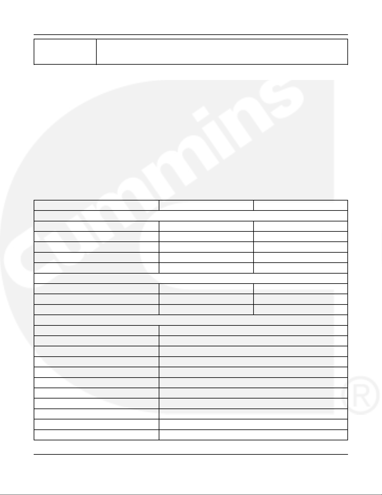
TABLE 2. GASOLINE MODEL SPECIFICATIONS
4.0 KY 3.6 KY
GENERATOR: 2-Pole Revolving Field, Self-Excited, 1-Phase, Microprocessor Regulated
Power 4000 Watts 3600 Watts
Frequency
Voltage 120 Volts 230 Volts
Current 33.3 Amps 15.7 Amps
Speed 3600 RPM 3000 RPM
FUEL CONSUMPTION:
No Load 1.1 l/h (0.29 gph) 0.79 l/h (0.21 gph)
Half Load 1.8 l/h (0.48 gph) 1.4 l/h (0.37 gph)
Fuel Load 2.7 l/h (0.71 gph) 2.2 l/h (0.58 gph)
ENGINE: 1-Cylinder, 4-Cyle, Spark Ignited, OHV, Air-Cooled, Mechanically Governed
Bore 79 mm (3.11 in)
Stroke 62 mm (2.44 in)
Displacement 304 cm3(18.5 in3)
Compression Ratio 8.5 : 1
Oil Capacity 1.5 liters (1.6 qt)
Intake Valve Lash (Cold) 0.05 mm (0.002 in)
Exhaust Valve Lash (Cold) 0.05 mm (0.002 in)
Spark Plug Gap 0.64 mm (0.025 in)
Spark Plug Torque 17 Nm (13 ft-lbs)
Ignition Timing 25° BTDC, non-adjustable
Magneto Air Gap 0.23–0.38 mm (0.009–0.015 in)
1
60 Hz 50 Hz
A041D129 (Issue 4) 9
2. Introduction 2-2015
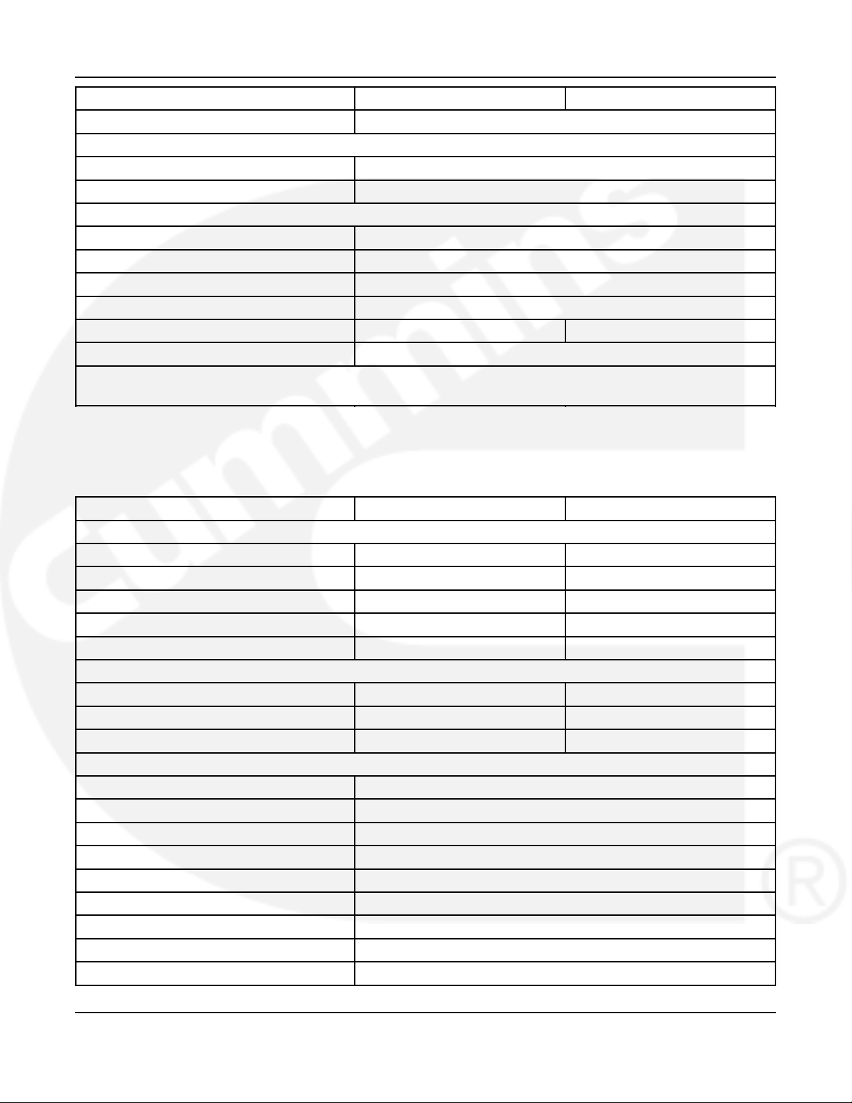
4.0 KY 3.6 KY
Compression 3.9 kgf/cm2(55.47 lbf/in2) @ 500 RPM
DC SYSTEM:
Battery Voltage 12 Volts
Minimum Battery Rating 450 CCA @ –18 °C (0 °F)
INSTALLATION:
Exhaust O. D. 28.7 mm (1.13 in)
Fuel Connection 1/4 inch barb fitting for gasoline hose
Minimum Free Air Inlet Area 258 cm2(40 in2)
Muffler Outlet Collar O.D. 1.13 in
Weight (with engine oil) 81 kg (178 lbs) 84 kg (184 lbs)
Minimum Compartment Size (H x D x W)
2
366 x 508 x 775 mm (14.4 x 20 x 30.5 in)
1. 60 Hz models are listed by CSA and the US Testing Company.
2. See the Installation Manual for additional considerations when sizing the generator set compartment.
2.5.2 LPG Model Specifications
TABLE 3. LPG MODEL SPECIFICATIONS
3.6 KY 3.3 KY
GENERATOR: 2-Pole Revolving Field, Self-Excited, 1-Phase, Microprocessor Regulated
Power 3600 Watts 3300 Watts
Frequency
Voltage 120 Volts 230 Volts
Current 30 Amps 14.3 Amps
Speed 3600 RPM 3000 RPM
FUEL CONSUMPTION:
No Load 0.7 kg/h (1.5 lbs/h) 0.5 kg/h (1.1 lbs/h)
Half Load 1.0 kg/h (2.2 lbs/h) 0.9 kg/h (2.0 lbs/h)
Full Load 1.5 kg/h (3.3 lbs/h) 1.3 kg/h (2.9 lbs/h)
ENGINE: 1-Cylinder, 4-Cycle, Spark Ignited, OHV, Air-Cooled, Mechanically Governed
Bore 79 mm (3.11 in)
Stroke 62 mm (2.44 in)
Displacement 304 cm3(18.5 in3)
Compression Ratio 8.5 : 1
Oil Capacity 1.5 liters (1.6 qt)
Intake Valve Lash (Cold) 0.05 mm (0.002 in)
Exhaust Valve Lash (Cold) 0.05 mm (0.002 in)
Spark Plug Gap 0.51 mm (0.020 in)
Spark Plug Torque 17 Nm (13 ft-lbs)
1
60 Hz 50 Hz
10 A041D129 (Issue 4)
2-2015 2. Introduction
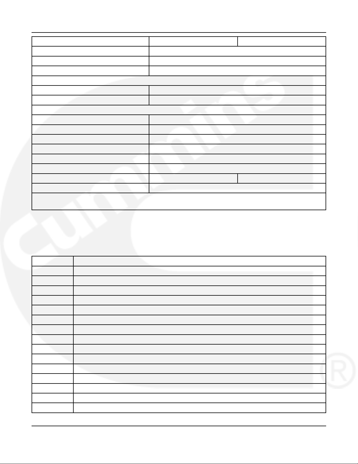
3.6 KY 3.3 KY
Ignition Timing 25° BTDC, non-adjustable
Magneto Air Gap 0.23–0.38 mm (0.009–0.015 in)
Compression 3.9 kgf/cm2(55.47 lbf/in2) @ 500 RPM
DC SYSTEM:
Battery Voltage 12 Volts
Minimum Battery Rating 450 CCA @ –18 °C (0 °F)
INSTALLATION:
Exhaust O. D. 28.7 mm (1.13 in)
Fuel Connection 5/8-18 UNC, SAE 45° Flare Fitting
Minimum Free Air Inlet Area 258 cm2(40 in2)
Muffler Outlet Collar O.D. 1.13 in
LPG Vapor Supply Pressure 228–330 mm (9–13 in) WC
LPG Liquid Connection Pressure 1/4-18 NPTF Tank Pressure
Weight 81 kg (178 lbs) 84 kg (184 lbs)
Minimum Compartment Size (H x D x W)
1. 60 Hz models are listed by CSA and the US Testing Company.
2. See the Installation Manual for additional considerations when sizing the generator set compartment.
2
366 x 508 x 775 mm (14.4 x 20 x 30.5 in)
2.6 List of Acronyms
TABLE 4. ACRONYM DEFINITIONS
Acronym Definition
AC Alternating Current
AGS Automatic Generator Start
AISI American Iron and Steel Institute
ANSI American National Standards Institute
API American Petroleum Institute
ASTM American Society for Testing and Materials (now known as ASTM International)
BS Build Standard
BTDC Before Top Dead Center
CARB California Air Resources Board
CCA Cold Cranking Amp
CFR Code of Federal Regulations
CO Carbon Monoxide
CPG Cummins Power Generation
CSA Canadian Standards Association
DC Direct Current
A041D129 (Issue 4) 11
2. Introduction 2-2015
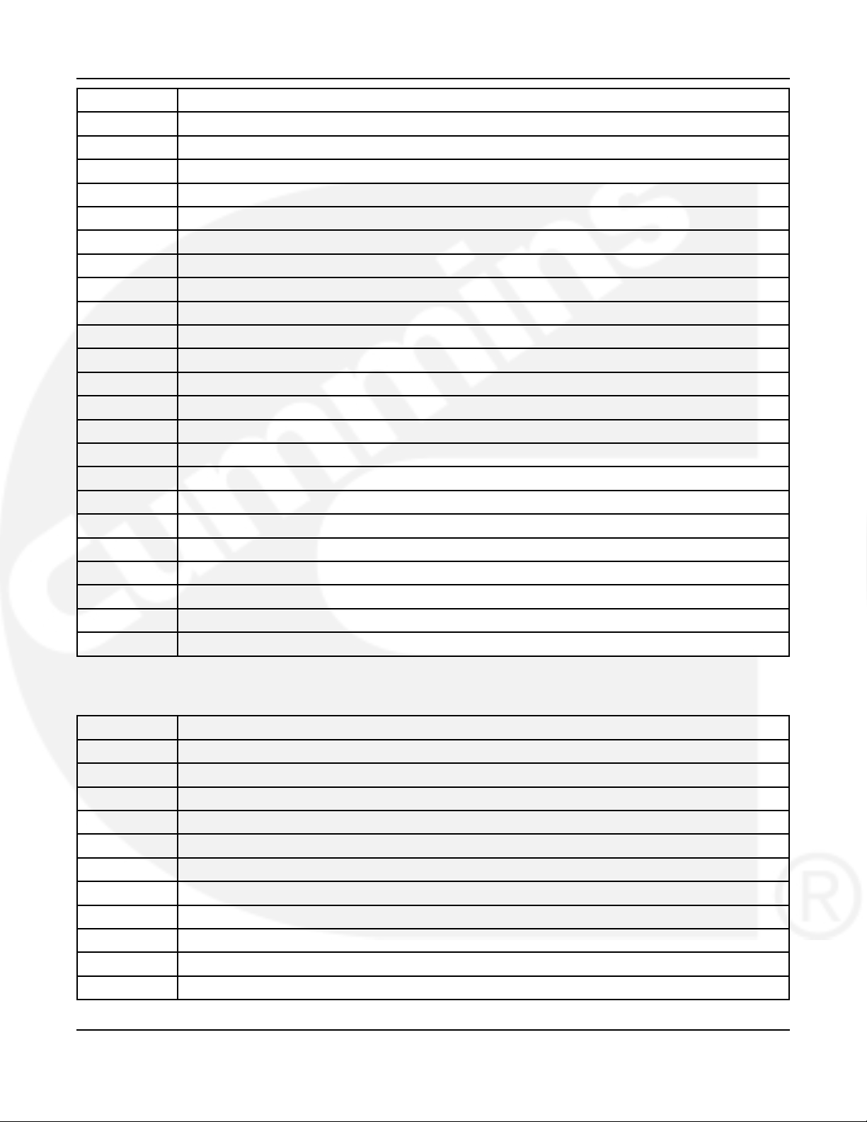
Acronym Definition
EEPROM Electronically Erasable Programmable Read Only Memory
EMC Electromagnetic Compatibility
EPA Environmental Protection Agency
GFCI Grounded Fault Circuit Interrupters
hp High Pressure
I.D. Inside Diameter
ISO International Organization for Standardization
LED Light-emitting Diode
LPG Liquid Petroleum Gas
NFPA National Fire Protection Agency
NPTF National Pipe Taper Fuel
O.D. Outside Diameter
OEM Original Equipment Manufacturer
PPE Personal Protective Equipment
PTO Power Take-Off
RAM Random Access Memory
ROM Read Only Memory
RV Recreational Vehicle
RVIA RV Industry Association
SAE Society of Automotive Engineers
UNC Unified National Coarse
US, U.S. United States
WC Water Column
TABLE 5. ACRONYMS FOR UNITS OF MEASUREMENT
Acronym Definition
Amp Ampere
C Celsius
cm centimeter
D Depth
F Fahrenheit
ft Feet, foot
ft-lbs Foot-pounds
g gram
gph Gallons per hour
H Height
Hz Hertz
12 A041D129 (Issue 4)
2-2015 2. Introduction
Acronym Definition
in Inch
kg kilogram
kg/h kilograms per hour
2
kgf/cm
kilogram-force per square centimeter
kW kilowatt
l/h Liters per hour
lb Pound
lbf/in2OR psi Pound per square inch
lbs/h Pounds per hour
m Meter
mm millimeter
Nm Newton meter
psi OR lbf/in2Pounds per square inch
qt Quart
RPM Revolutions per Minute
VAC Volts Alternating Current
VDC Volts Direct Current
W Watts, Width
A041D129 (Issue 4) 13

2. Introduction 2-2015
This page is intentionally blank.
14 A041D129 (Issue 4)

3 Location, Mounting, and Ventilation
The location, mounting, and ventilation of a generator set must be such that mounting is secure,
engine exhaust and fuel vapors are prevented from entering the vehicle, rain and road debris
are prevented from entering the generator set, and ready access is afforded for operating the
generator set and performing periodic maintenance.
3.1 Location
Typical locations for generator set installation are shown below.
• The location must provide:
• Ready access for starting and stopping the generator set and performing all periodic
maintenance.
• Separation from sources of flammable vapors, such as batteries and fuel tanks, which
the generator set could ignite.
• Access for connecting and disconnecting fuel lines, battery cables, remote control
wiring, and AC wiring.
• Access to single fuel pump screw after removal of control board through service door.
• Access from below for draining engine oil.
• Unobstructed space below the generator set for proper cooling air flow.
• The generator set must not share a compartment or ventilation with batteries or fuel tanks.
An operating generator set can ignite flammable vapors. Make sure that in the first 305 mm
(12 in) of ground clearance there is at least 152.4 mm (6 in) of unobstructed space below
the generator set and open on at least three sides, which is required for proper cooling air
flow.
• Locate or shield the generator set cooling air openings from direct rain, road splash and
debris thrown up by the road wheels.
NOTICE
Mudflaps, air ducts, and deflectors must be used to prevent road debris and tire spray from
going into the generator set.
• The generator set housing is not rain proof. If the generator set is installed where snow
and rain will hit the top of the generator set, a sheet metal or plastic cover should be used
to prevent large amounts of water from running in the seams of the generator set housing.
• Space to mount the generator set with at least 25.4 mm (1 in) clearance on the left side,
25.4 mm (1 in) clearance at the top, 38.1 mm (1.5 in) clearance in front, and 6.35 mm (1/4
in) clearance on the remaining sides of the generator set. Minimum clearances apply to
any thermal or acoustic insulation with which a compartment may be lined.
A041D129 (Issue 4) 15
3. Location, Mounting, and Ventilation 2-2015
NOTICE
For rooftop or other high acceleration locations:
Certain locations for generator set installations can result in 30+ g forces affecting the generator
set. These high road input forces can cause generator set performance issues, from rough
running or stalling to many different types of broken generator set components. It is highly
recommended that the generator set not be located more than 1.524 m (5 ft) above the floor and
aft of the rear axle(s) on a trailer or motorized application.
Damage due to high road input forces (as follows) will not be covered under warranty:
• Broken generator mounts
• Broken exhaust components
• Damaged housings or shrouds from excessive internal generator set component movement
• Torn out wiring harnesses
• Stalling or rough running while the vehicle is in motion
Locating the generator set in these limited access areas also affects proper maintenance. Major
engine damage due to lack of maintenance will not be covered under warranty.
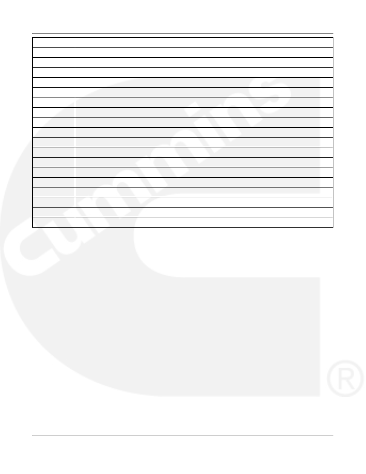
3.1.1 Typical Generator Set Locations - Class A RV
FIGURE 1. TYPICAL GENERATOR SET LOCATIONS - CLASS A RV
16 A041D129 (Issue 4)
2-2015 3. Location, Mounting, and Ventilation
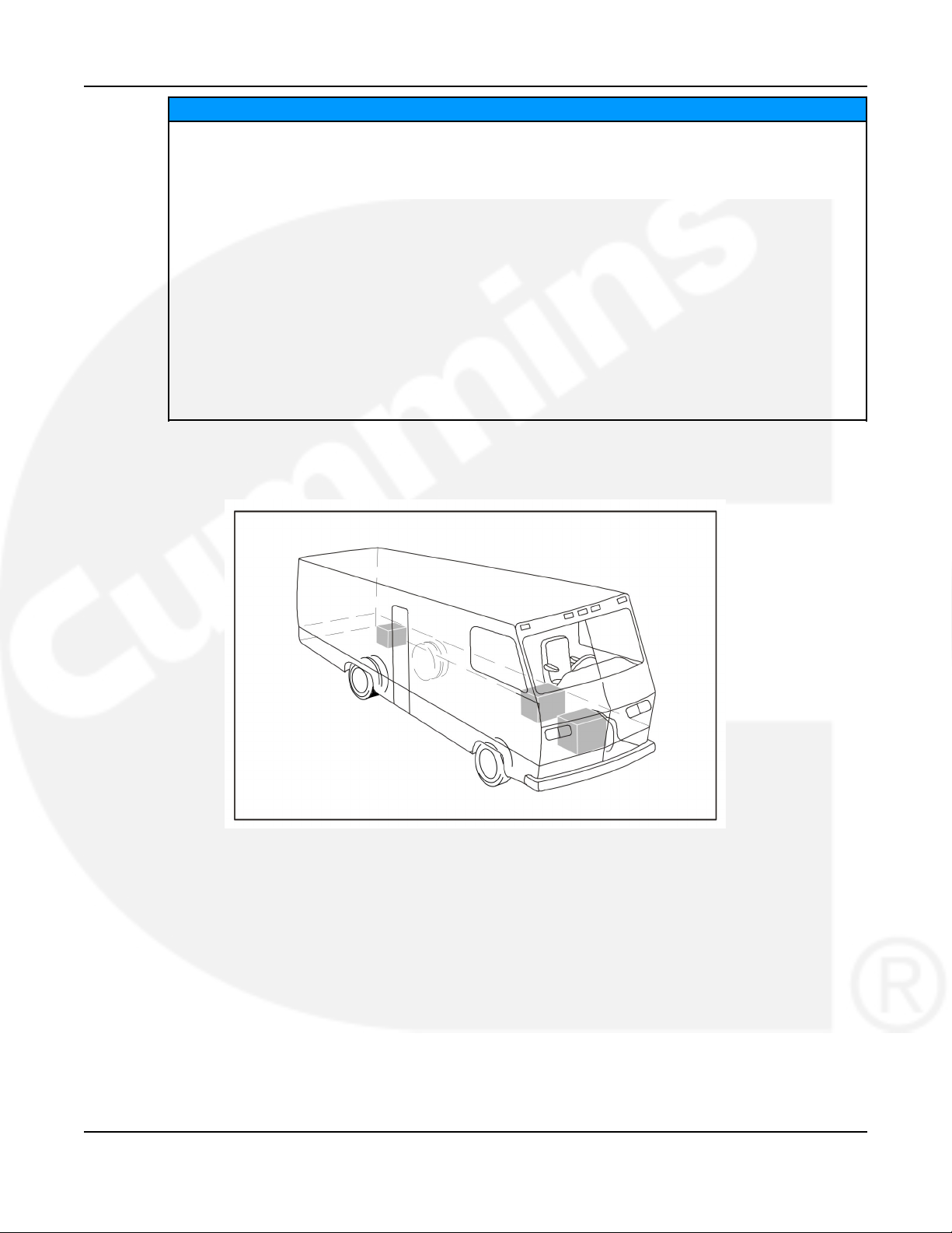
3.1.2 Typical Generator Set Locations - Class C RV
FIGURE 2. TYPICAL GENERATOR SET LOCATIONS - CLASS C RV
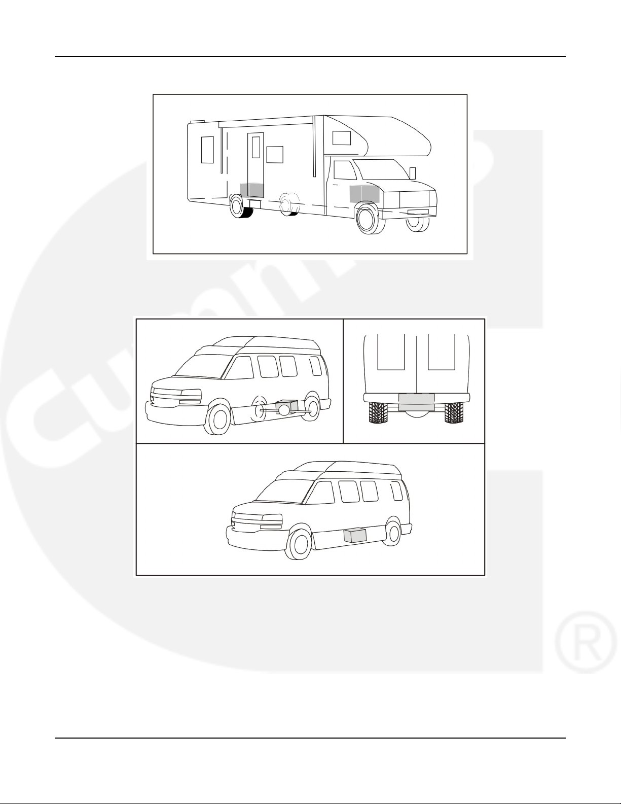
3.1.3 Typical Generator Set Locations - Class B Van
FIGURE 3. TYPICAL GENERATOR SET LOCATIONS - CLASS B VAN
A041D129 (Issue 4) 17
 Loading...