

Page 1
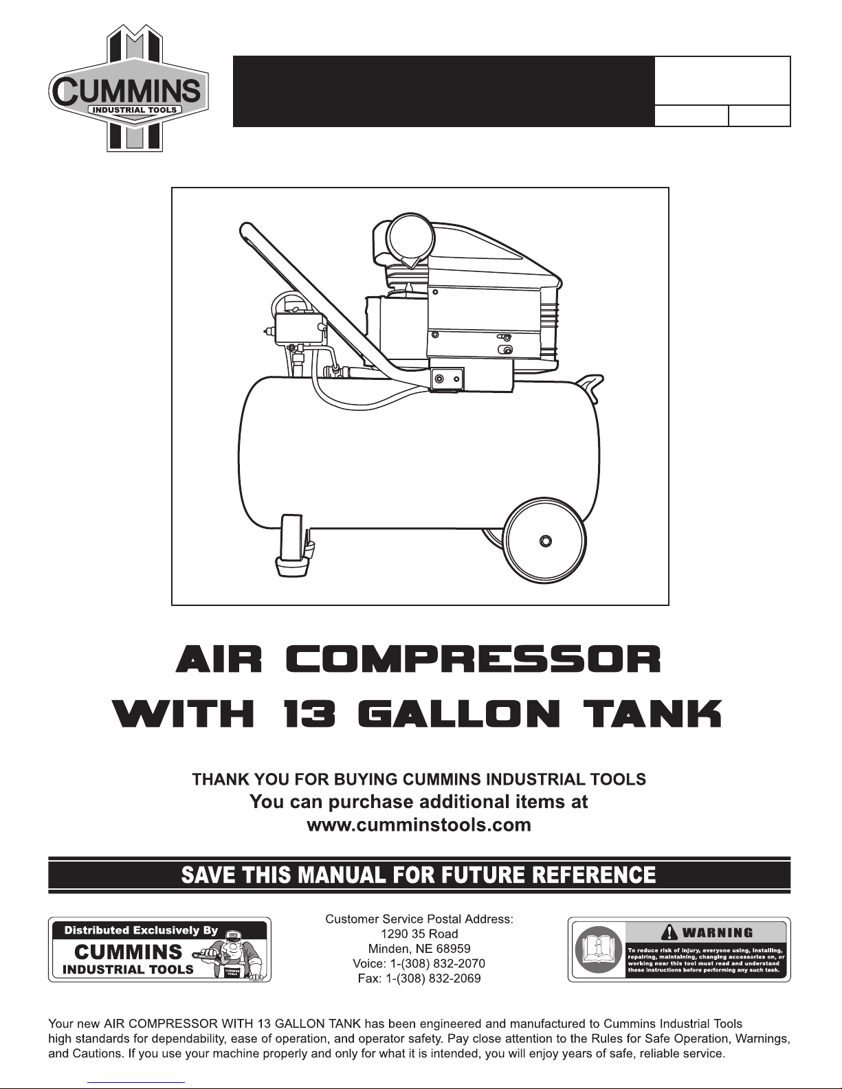
Assembly & Instruction Manual
ITEM 1204
VENDOR: A 1SERIES:
Page 2
TABLE OF CONTENTS
- 1 -
Introduction
1
General Safety Rules
2
Specific Safety Rules
3-4
Product Specifications
4
Unpacking
4
Maintenance
6-7
Exploded Diagram & Parts List
9
Troubleshooting
8
Features
5
Applications
5
Operation
5-6
INTRODUCTION
THIS PRODUCT has many features for making the use of this product more pleasant and enjoyable. Safety,
performance, and dependability have been given top priority in the design of this product making it easy to
maintain and operate.
!!
WARNING: Do not attempt to use this product until you thoroughly read and completely understand the operator’s manual. Pay close attention to the safety rules, including Dangers, Warnings, and Cautions. If you use your product properly and only as
intended, you will enjoy years of safe, reliable service.
!!
Look for this symbol to point out important safety precautions. It means attention!!! Your safety is involved.
!!
WARNING: The operation of any tool can result in foreign objects being
thrown into your eyes, which can result in severe eye damage. Before beginning operation, always wear safety goggles or safety glasses with side shields
and a full face shield when needed. We recommend Wide Vision Safety Mask
for use over eyeglasses or standard safety glasses with side shields. Always
wear eye protection which is marked to comply with ANSI Z87.1.
Page 3

!!
GENERAL SAFETY RULES
WARNING: The warnings, cautions, and instructions discussed in this instruction
manual can not cover all possible conditions and situations that may occur. It must be
understood by the operator that common sense and caution are factors which can not be
built into this product, but must be supplied by the operator.
!!
WARNING: When using tool, basic safety precautions should always be followed to
reduce the risk of personal injury and damage to equipment. Read all instructions before
using the tool!
Do not operate tools if under the influence of alcohol or drugs. Read warning
labels on prescriptions to determine if your judg
ment or reflexes are impaired while taking drugs. If
there is any doubt, do not operate the tool.
Replacement parts and accessories.
When servicing, use only identical replacement
parts. Use of any other parts will void the warranty.
Only use accessories intended for use with this
tool. Approved accessories are available from
Cummins Industrial Tools.
Check for damaged parts. Before using any
tool, any part that appears damaged should be
carefully checked to determine that it will operate
properly and perform its intended function. Any
part that is damaged should be replaced.
Stay alert. Watch what you are doing, use
common sense. Do not operate any tool when you
are tired.
Remove adjusting keys and wrenches.
Check that keys and adjusting wrenches are
removed from the tool or machine work surface
before starting work.
Maintain tools with care. Keep tools sharp
and clean for better and safer performance. Follow
instructions for lubricating and changing accesso
ries. The handles must be kept clean, dry, and free
from oil and grease at all times.
Do not overreach. Keep proper footing and
balance at all times. Do not reach over or across
running machines.
Use eye protection. Always wear ANSI
approved impact safety glasses underneath a full
face shield during use. Also, wear heavy duty work
gloves.
Dress properly. Do not wear loose clothing or
jewelry as they can be caught in moving parts.
Protective, electrically non-conductive clothes and
non-skid footwear are recommended when work
ing. Wear restrictive hair covering to contain long
hair.
Use the right tool for the job. Do not
attempt to force a small tool or attachment to do
the work of a larger industrial tool. There are
certain applications for which this tool was
designed. It will do the job better and more safely
at the rate for which it was intended. Do not modify
this tool and do not use this tool for a purpose for
which it was not intended.
Store idle equipment. When not in use, tools
must be stored in a dry location to inhibit rust.
Always lock up tools and keep out of reach of
children.
Keep children away. Children must never be
allowed in the work area. Do not let them handle
machines, tools or extension cords.
Additional work area conditions. Do not
use machines or power tools in damp or wet loca
tions. Do not expose to rain. Keep work area well
lighted.
Work area conditions. Cluttered areas invite
injuries.
- 2 -
Page 4

SPECIFIC SAFETY RULES
- 3 -
Never use the compressor without connection to a properly grounded outlet with the specified voltage and
fuse protection.
Do not use the compressor in a wet or explosive environment.
Never attempt maintenance or adjustment with power connected of the equipment in operation.
This valve is factory installed to prevent the air receiver from damage should a malfunction occurs in the compressor pump.
It is factory set at a specified limit for your particular model and adjustments should never be tampered by
yourself or the warrant will automatically be void otherwise.
The air pressure switch is set at the factory optimum performance of you equipment. Never bypass or
remove this switch as serious damage to equipment or personal injury could result from too high an air pres
-
sure.
Air compressor get hot while in operation. Never touch the motor, discharge tubing, or compressor pump
while in operation.
The compressor operates automatically while the power is connected.
Never attempt any adjustment with the power on.
Compressor air from the unit may contain carbon monoxide. Air produced is not suitable for breathing
purposes.
Always use a respirator when spraying paint or chemicals.
Always wear safety glasses or goggles when spraying air.
Over pressurizing the air receiver could cause an explosion or rupture. To protect over pressurizing a factory
preset safety valve is included. Do not remove, make adjustments or substitutions to this valve.
Occasionally pull the ring on the valve to make sure that the valve operates freely. If the valve does not operate freely, it must be replaced. Never weld to, drill into, or change the air receiver in any way.
Electrical Shock Hazard
Tank Safety Valve
Pressure Switch
Motor and Compressor Pump
Compressed Air Caution
Air Receiver
Page 5

If any of the above conditions are changed or tampered with this will result in voiding of the manufacturer’s
warranty. Be advised that any replacement parts should be purchased with the same specifications as the
original equipment. Please contact your authorized dealer for replacement parts or specifications.
Do not smoke while operating the air compressor. To avoid the ignition of a fire or explosion, never spray
where sparks or flame is present.
2.5 HP (3HP peak)
13 Gallon
115V, 60Hz, 15 Amp
3400 RPM
Maximum pressure 115 PSI
5.2 SCFM @ 40 PSI, 4.2 SCFM @ 90 PSI
- 4 -
PRODUCT SPECIFICATIONS
Do not discard the packing material until you have carefully inspected and satisfactorily operated the tool.
Make sure that all items listed in the packing list are included.
UNPACKING
When unpacking the tool:
INSTRUCTIONS
Carefully remove the tool and accessories from the box.
Inspect the tool carefully to make sure no breakage or damage
occurred during shipping.
WARNING: If any part are miss-
ing do not operate the tool until the
missing parts are replaced. Failure to
do so could result in possible serious
personal injury.
!!
SPECIFIC SAFETY RULES
Other
Page 6

- 5 -
APPLICATIONS
FEATURES
OPERATION
Tank with one regulator, one coupler and two gauges
50% duty cycle
Single phase, single stage
ASME approved safety valve
Finned copper outlet tube
Direct drive compressor pump
Oil lubrication for long life
Thermal overload protection for safety and reliability
To compress air, the pistons move up and down in the cylinder. On the down stroke, air is drawn in through
the valve inlet. The discharge valve remains closed. On the upstroke of the piston, air is compressed. The
inlet valve closes and compressed air is forced out through the discharge valve, through the check valve and
into the air receiver. Working air is not available until the compressor has raised the air receiver’s pressure
above that required at the air service connection. The air inlet filter openings must be kept clear of obstruction
or else it could reduce air delivery of the compressor.
Depending on the S.C.F.M. draw of the tools being operated, your new air compressor can be used for
operating:
Note: An air pressure regulator is usually necessary for most of these applications.
paint sprayers
air tools
grease guns
airbrushes
caulking guns
sandblasters
inflating tires and plastic toys
spraying week killer and insecticides
etc.
General Description of Operation
Page 7

- 6 -
OPERATION
MAINTENANCE
Installation and Location
Assembly
Locate the compressor in a clean, dry and well-ventilated area. The compressor should be located 12 to 18
inches away from a wall or any other obstruction that could interfere with the air flow through the fan blade
belt wheel. Place the compressor on a firm level surface. The compressor is designed with heat dissipation
fins that allow for proper cooling. Keep the fins and other parts that collect dust or dirt clean. A clean compres
sor runs cooler and provides longer service. Do not place rags, containers, or other material on top of the
compressor.
Remove air filter from plastic bag and screw it into the thread hole. Be sure to always clean air filter before
and after use.
Remove the clear plastic oil cap and replace it with the oil cap.
Disconnect electrical power
Drain air tank of pressure.
Before doing any maintenance or adjustments to your air compressor, the following safety precautions should
be taken:
Daily or before each use
Weekly
Monthly
During the break-in period, nuts and bolts have a tendency to loosen up. After two weeks tighten all nuts and
bolts including head bolts then check everything once a month to make sure all nuts and bolts stay tight.
Check oil level.
Drain condensation from tank.
Check for any unusual noise or vibration.
Be sure all nuts and bolts are tight.
1-
Clean air filter by opening air filter cap. Remove the filter element and clean thoroughly with soap and water.
Rinse thoroughly and allow to dry completely before assembly.
1-
Inspect air system for leaks by applying soapy water to all joints. Tighten those joints if leakage is observed.
1-
2-
Clean breather holes on oil check dipstick.
2-
3-
4-
Page 8

- 7 -
MAINTENANCE
Change compressor oil
Replace oil more often if compressor is used near paint spraying operations or in dusty environments.
Refill with the recommended oil to the red dot in the oil level sight glass.
Make sure all pressure and water is released from tank.
1-
Sit air compressor on level surface. The oil level should be at the red dot on the oil level sight glass.
1-
Remove the oil drain plug. Allow oil to drain completely.
1-
Make sure the amount of oil is adequate before each use.
1-
Turn the power switch off after each use of the compressor.
1-
2-
If oil level is low, remove oil fill plug, add enough oil to bring level to the read dot in the oil level sight glass.
Replace oil fill plug before starting compressor.
2-
Replace the oil drain plug (we recommend the use of a sealing compound or Teflon tape to avoid leakage).
2-
Check all nuts and screws for secured tightness.
2-
Open drain valve underneath the tank and release all the air and moisture inside.
2-
3-
Make sure wiring fuse and power supply is correctly installed.
3-
The pressure gauge should now fall back to 0 PSI.
3-
4-
Release all the air from the attached air tool, then disconnect hose from the quick coupler.
4-
Turn on power switch. The pressure inside the tank will increase until if reaches 90 PSI. The system will then
automatically shut down at this point.
5-
Connect air tool and start the compressor to begin use. Note: Be sure to check manufacturer’s maximum
pressure rating for air tools and accessories. Compressor outlet pressure must be regulated to never exceed
the maximum pressure rating of the tool.
Use the regulator knob to control the amount of air pressure for the attached ail tool. Turn the knob clockwise
to increase air pressure and counter-clockwise to reduce air pressure.
To enable the best air pressure release and avoid air leakage, use Teflon tape to wrap around hose and
coupler thread.
250 hours or six (6) months (whichever comes first)
Compressor with oil level sight glass
Draining the oil
Starting compressor
Air release
Compressor Lubrication
Note: Check the oil quantity and quality before operating the compressor. Do not add or change oil while the
compressor is in operation. Use only SAE 20 or SAE 30 weight non-detergent oil.
3-
6-
7-
8-
Page 9

- 8 -
TROUBLESHOOTING
Trouble
Possible
Corrective Action
No start condition
Fuse blown or circuit breaker tripped.
Check for cause of blown fuse/breaker and
replace or reset.
Replace check valve.
Check for proper adjustment and if problem
persists, replace pressure switch.
Replace oil with SAE 30 or SAE 20 weight nondetergent oil.
Drain crank case and fill to proper level.
Air pressure regulated too high.
Clean or replace filter.
Check wiring connections.
Press the reset button or wait for automatic reset.
Check valve manually by pulling upward on rings.
If condition persists, replace valve.
Clean or replace as necessary.
Improper oil viscosity.
Too much oil in crank case.
Compressor overheated.
Restricted air filter.
Loose electrical connections.
Overheated motor.
Air leak in safety valve.
Restricted air filter.
Defective check valve.
Defective pressure switch or improper adjustment.
Low Pressure
Safety valve releasing
Oil discharge in air
For assistance in solving parts problems please refer to the parts and components for our air compressors
by number.
When a new replacement is needed include the model number of the air compressor, part number and quantity required.
If a new assembly is required, include the model number of the air compressor undergoing repair (according
to the nameplate, the part name, part number and quantity required according to the number on the parts
diagram).
Page 10

- 9 -
EXPLODED DIAGRAM & PARTS LIST
1.
Crank Case
19.
Cylinder
37.
Fan
55.
Bolt
2.
Crank Shaft
20.
Washer
38.
Rear Cap
56.
Safety Valve
3.
Crank Case Cover
21.
Bolt
39.
Stator
57.
Pressure Switch
4.
Crank Case Cover
22.
Valve Gasket
40.
Bearing
58.
Pressure Gauge
5.
Bolt
23.
Valve
41.
Rotator
59.
Connect
6.
Cover
24.
Valve Assembly
42.
Bearing
60.
Regulator
7.
Oil Glass
25.
Gasket
43.
Shaft Seal
61.
Air Cock
8.
Bolt
26.
Cylinder Head Gasket
44.
Tank
62.
Pressure Gauge
9.
Spring
27.
Elbow Exhaust
45.
Bolt
63.
Unloading Screen
10.
Breather
28.
Cylinder Heed
46.
Washer
64.
Unloading
11.
Bolt
29.
Washer
47.
Wheel
65.
Unloading Elbow
12.
Connect Rod
30.
Bolt
48.
Washer
66.
Check Valve
13.
Spring
31.
Air Filter
49.
Washer
67.
Exhaust Pipe Unit
14.
Wrist Pin
32.
Capacitance
50.
Drain Cock
68.
Exhaust Pipe
15.
Piston
33.
Washer
51.
Bolt
69.
Cable Connect
16.
Piston Ring
34.
Bolt
52.
Washer
70.
Plug
17.
Washer
35.
Convoy
53.
Cushion Foot
18.
Gasket
36.
Bolt
54.
Washer
 Loading...