

Page 1
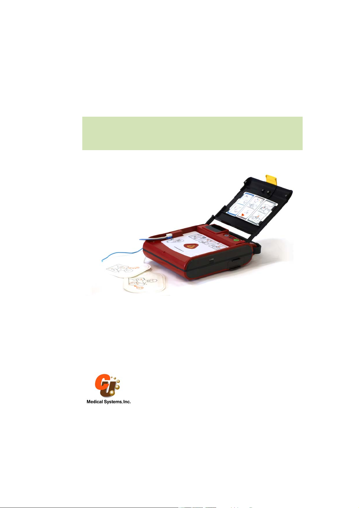
i-PAD NF1200
Service Manual
CU Medical Systems, Inc.
1
Page 2
i-PAD NF1200
Quick Reference Card
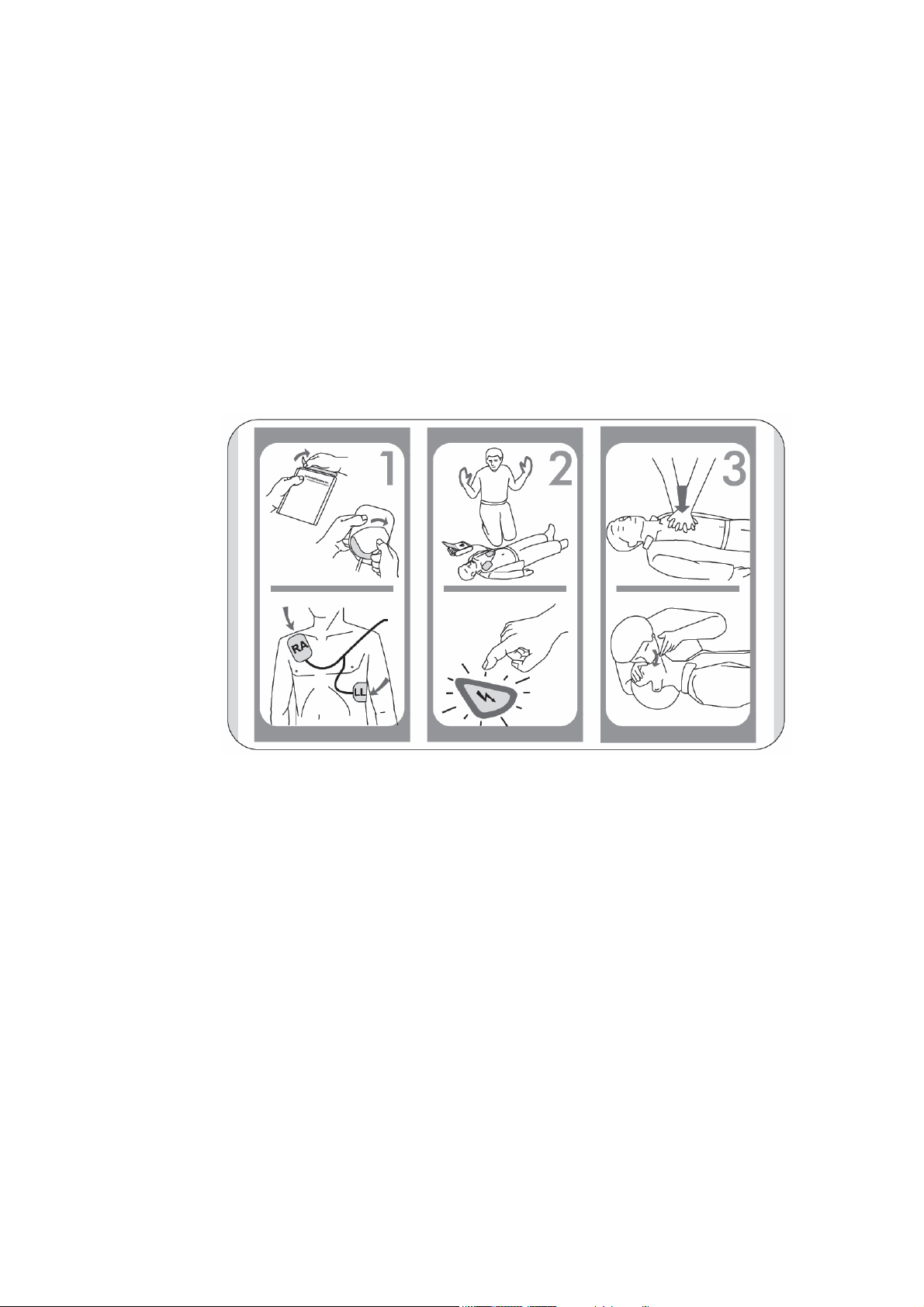
Rescue Steps
1. Connect the defibrillator pads to the i-PAD and then place on patient.
2. Stand clear and press the SHOCK button if instructed.
3. Administer CPR
2
Page 3

Notice
i-P AD NF 1200 Service Manual
CU Medical Systems, Inc. reserves the right to make changes on the device specifications contained in this manual
at any time without prior notice or obligation to customers.
Printed in the Republic of Korea
Publication Date: March 2007
Service Manual Part No.:
© 2007 CU Medical Systems, Inc.
No part of this manual may be reproduced without the permission of CU Medical Systems, Inc.
3
Page 4

Table of Contents
Table of Contents ...................................................................................................................4
1. Introduction........................................................................................................................5
1.1 The i-PAD NF1200.......................................................................................................................................... 5
1.2 Service Manual Overview ...............................................................................................................................5
1.3 Warnings, Cautions, and Notes........................................................................................................................ 5
1.4 i-PAD NF1200 Device Details ........................................................................................................................ 5
1.4.1 Operating Controls, Indicators and Accessories ...................................................................................7
1.4.1.1 Device Parts Illustration .............................................................................................................. 7
1.4.1.2 Accessories ................................................................................................................................10
1.4.2 Voice and Text Prompts .......................................................................................................................11
2. Routine Maintenance ....................................................................................................... 13
2.1 Overview........................................................................................................................................................13
2.2 Cleaning the i-PAD NF1200..........................................................................................................................13
2.3 Periodic Safety and Functional Checks ......................................................................................................... 14
2.4 Batteries .........................................................................................................................................................16
3 Performance Verification .................................................................................................. 17
3.1 Self-Tests........................................................................................................................................................17
3.2 Automatic Self-Tests...................................................................................................................................... 18
3.3 Battery Insertion Test..................................................................................................................................... 18
3.4 Self Test Results.............................................................................................................................................18
3.4.1 Automatic Self Tests ............................................................................................................................ 18
3.4.2 Battery Insertion Test...........................................................................................................................18
3.5 Shock Waveform Verification Test................................................................................................................20
3.6 Data Transmission Test..................................................................................................................................22
3.7 Impedance Measurement Test .......................................................................................................................23
3.8 Voice and Text Prompt Testing......................................................................................................................24
4 Troubleshooting ................................................................................................................ 26
4.1 How to Use This Section ...............................................................................................................................26
4.2 Who Must Perform Repairs ........................................................................................................................... 26
4.3 Replacement Level Supported....................................................................................................................... 26
4.4 Troubleshooting Guide .................................................................................................................................. 26
5 Disassembly and Repair....................................................................................................33
5.1 Disassembly ................................................................................................................................................... 34
5.2 Reassembly ....................................................................................................................................................40
6 Assembly Diagram............................................................................................................41
Technical Specifications ......................................................................................................43
Electromagnetic Compatibility ............................................................................................49
4
Page 5

1. Introduction
1.1 The i-PAD NF1200
The i-PAD is a semi-automated external defibrillator designed for minimally trained individuals. It provides
simple and direct voice prompts and indications for a straightforward rescue operation. It is lightweight and
battery powered for maximum portability.
1.2 Service Manual Overview
This Service Manual contains service information and instructions intended for qualified service personnel who
will repair and service the i-PAD NF1200.
1.3 Warnings, Cautions, and Notes
“WARNING” – used to denote conditions, hazards, or unsafe practices that can result in serious personal injury or
death.
“CAUTIONS” – used to denote conditions, hazards, or unsafe practices that can result in minor personal injury,
damage to the i-PAD NF1200, or loss of data stored in it.
“NOTES” – used to denote items that are important during installation, operation, or maintenance of the i-PAD
NF1200.
1.4 i-PAD NF1200 Device Details
The following description and diagrams show the details of the i-PAD NF1200.
5
Page 6
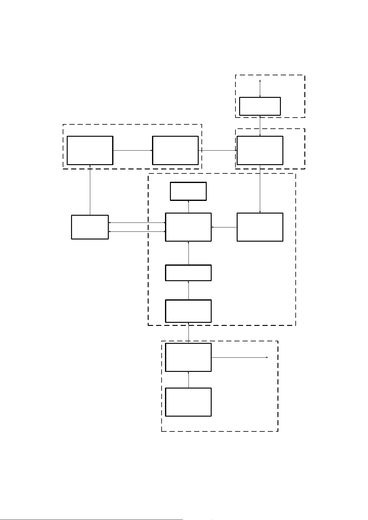
Data Storage and Backup Subsystem
To External
Device
Data Storage and
Backup
Subsystem
Analog Front-end
Patient
Analog Front-end Subsystem
ECG and
impedance
signals
Analog to Digital
Converter
Internal Disarm
Resistor
Switches
H-Bridge
Therapy Capacitor
ECG and
impedance
data
High Voltage Subsystem
High Voltage
Electrical
energy
High Voltage
Electrical
energy
Main Digital Subsystem
Main
Microprocessor and
Memory
Defibrillation
Control Signals
Defib Control
Microprocessor and
Memory
High Voltage Power
Supply
12V
Electrical
energy
General Power
Supply
15V, 5V, 3.3V, -3.3V, 1.8V
To various parts
of the device
Battery Pack
Power Supply Subsystem
i-PAD NF1200 Functional Block Diagram
6
Page 7
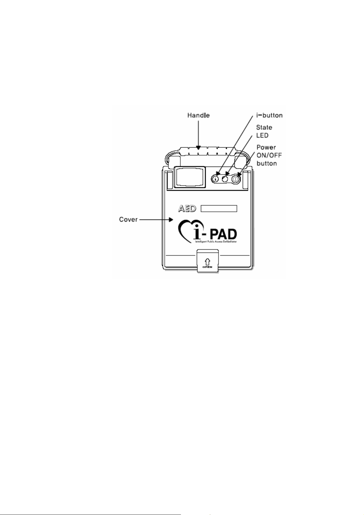
1.4.1 Operating Controls, Indicators and Accessories
1.4.1.1 Device Parts Illustration
Top View of the i-PAD NF1200 with its cover closed
7
Page 8
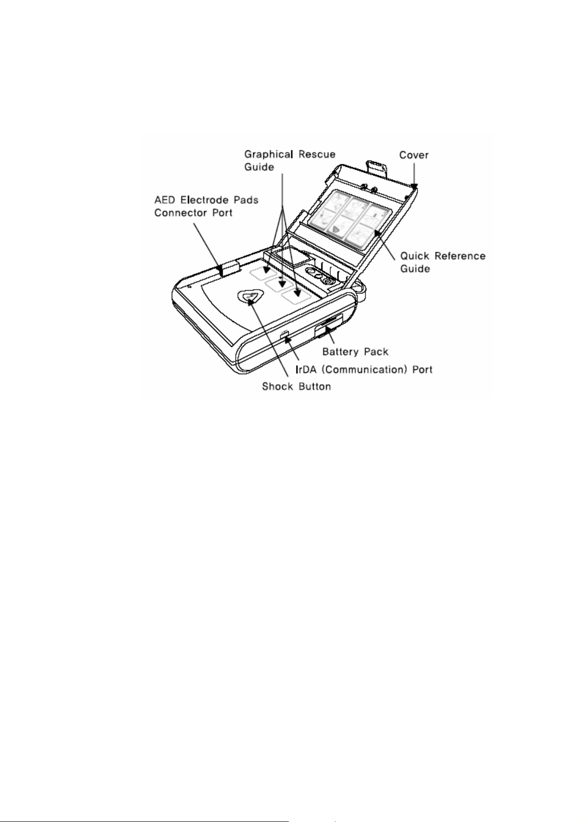
Perspective view of the i-PAD NF1200 with its cover open
8
Page 9

Power ON/OFF
Button
i-Button Press this button to:
State LED Indicates the status of the i-PAD
Handle An easy-grip carrying handle for increased portability of the i-PAD.
Cover Covers the front panel of the i-PAD and retains the defibrillator electrode pads package.
SHOCK button Press this button when the i-PAD prompts you to “Press the flashing orange button now”.
AED electrode
pads connector
port
Graphical Rescue
Guide
Quick Reference
Guide
Battery Pack Provides power to the i-PAD.
IrDA
Communication
Port
Press this button to turn the i-PAD ON or OFF.
• Get information regarding the i-PAD’s last usage (usage time and number of
shocks delivered.)
• Get information regarding errors that were detected during self-tests.
• Toggle between compression-to-breathing ratios during CPR (30:2 and 15:2)
• blinking green: the i-PAD is in standby mode and ready for a rescue operation
• solid green: the i-PAD is in rescue mode.
• blinking red: the i-PAD detected a system error or low battery level during a self-
test.
• solid blue: the i-PAD is conducting a self-test.
• solid white: the i-PAD is in administration mode. It announces last use
information and it senses and waits for a possible data
transfer to a personal computer.
Pressing this button delivers a defibrillation shock to the patient.
Plug the connector of the AED electrode pads into this port
Guides you by indicating the current step in the rescue process.
A printed card that summarizes the steps of a rescue process using the i-PAD.
Initiates a self-test upon insertion.
Port for sending and receiving data to and from a personal computer.
9
Page 10
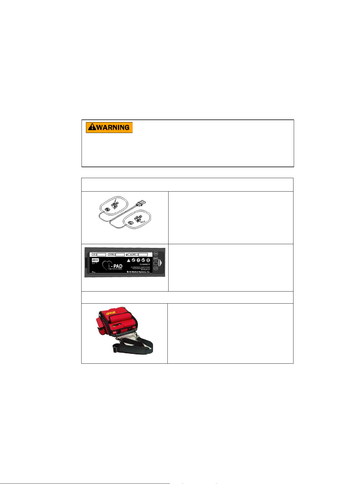
1.4.1.2 Accessories
Only parts and accessories approved by CU Medical Systems, Inc. must be used with the i-PAD NF1200. Using
parts and accessories that are not approved by CU Medical Systems, Inc. may degrade performance.
Using accessories and cables other than the ones specified in this manual may result in increased
ELECTROMAGNETIC EMISSIONS or may decrease the ELECTROMAGNETIC IMMUNITY of the
i-P AD NF 1200
Replacement accessories and consumables must be sourced only from CU Medical Systems, Inc. or its
authorized representatives.
Standard Accessories
Defibrillator Electrode Pads and
Connector Assembly
Disposable, non-rechargeable, LiMnO2
battery pack
Optional Accessory
Self adhesive, pre-gelled defibrillator electrode pads used to
acquire the ECG signal from the patient and to deliver the
defibrillation shock to the patient.
Power source of the i-PAD NF1200. This battery is inside the
case of the device. RETURN the i-PAD NF1200 to an
authorized service representative in case the battery pack needs
to be replaced.
Used to store the i-PAD NF1200 and the accessories needed for
a rescue operation.
Carrying Case
10
Page 11

1.4.2 Voice and Text Prompts
Prompts
The i-PAD NF1200 guides you throughout a rescue operation using voice prompts and other audio-visual
indicators. The following table lists the voice prompts of the i-PAD NF1200.
Table: Voice prompts and their meanings.
Prompt Meaning/Definition
Attach pads
Do not touch the patient
Analyzing heart rhythm
Shock advised
Stand clear
Press the flashing orange button, now.
Deliver shock, now.
Shock delivered
Begin CPR, now
Push the chest down, fast, two inches
Give two breaths. Breath, breath
The shock button was not pressed
No shock advised
Check pulse
If no pulse, begin CPR
System shutting down
Press the flashing orange button, now
Press the flashing blue i-Button
Administration mode
• Indicates that you have to attach the defibrillator electrode
pads to the bare chest of the patient and to the i-PAD
NF1200
• Indicates that you or any bystander must not touch the
patient.
• Indicates that the i-PAD NF1200 is analyzing the ECG of
the patient. Nobody must touch the patient.
• Indicates that a shockable ECG rhythm has been detected
and the i-PAD NF1200 is preparing for a shock delivery.
• Emphasizes the need to stay clear of the patient. Given just
before the prompt to deliver shock is given.
• Indicates that you have to press the shock button in order
for the shock to be delivered. The shock will only be
delivered if you press the shock button.
• Indicates that a shock has been delivered to the patient.
• Indicates the start of CPR.
• You may touch the patient after this prompt is given.
• Indicates that you have to push the chest down for about
two inches during CPR. The chest has to be pushed down
fast.
• Indicates that you have to give artificial breaths to the
patient. Time the breaths with the breathing guide.
• Indicates that you did not press the shock button within 15
seconds when the i-PAD NF1200 prompted you to do so.
• Indicates that the i-PAD NF1200 detected a nonshockable
rhythm.
• Indicates that you have to check the pulse of the patient.
• Indicates that if there is no pulse, you have to begin CPR.
• Indicates that the ON/OFF button of the i-PAD NF1200
has been pressed to turn it OFF.
• Given during battery insertion test. Indicates that you have
to press the SHOCK button so that the i-PAD NF1200 can
test its functionality.
• Given during battery insertion test. Indicates that you have
to press the i-Button button so that the i-PAD NF1200 can
test its functionality.
• Indicates that the i-PAD NF1200 is in administration mode
11
Page 12

Table: Voice prompts and their meanings, continued
Prompt Meaning/Definition
Device usage time is 10 minutes
Shock delivery is 4 times
• Given during administration mode. Indicates the duration
(in minutes) that the i-PAD NF1200 was ON. In this case,
the i-PAD NF1200 was ON for 10 minutes during its
previous usage.
• Given during administration mode. Indicates the number
of shocks that the i-PAD NF1200 delivered. In this case,
the i-PAD NF1200 delivered four shocks during its
previous usage.
12
Page 13

2. Routine Maintenance
2.1 Overview
The i-PAD NF1200 does not need any routine maintenance or calibration of its internal electronic subsystems.
Whenever service is necessary, please contact CU Medical Systems, Inc. or any of its authorized representatives.
2.2 Cleaning the i-PAD NF1200
After each use, clean the i-PAD NF1200 using a soft, damp cloth moistened with any of the following solvents:
Soap and water
70% solution isopropyl alcohol
Chlorine bleach and water mixture (30 ml bleach/liter of water)
Ammonia-based cleaners
Hydrogen peroxide
Do not immerse any part of the i-PAD NF1200 in fluids
Do not let any fluid enter the case of the device.
Do not spill liquids on the case of the device.
Do not use strong, acetone-based cleaners in cleaning the device.
Do not use abrasive materials in cleaning the unit, especially on the LCD display and the infrared
filter on the IrDA port.
Do not sterilize the i-PAD NF1200.
13
Page 14

2.3 Periodic Safety and Functional Checks
It is recommended that the following periodic checks be performed to ensure that the device and its accessories are
in good condition and ready for any emergency.
Maintenance Activities
Frequency Activity Actions to be T aken
Daily
Monthly and after
each use
Check the i-PAD NF1200 for any error
messages that might have been
generated during the Daily Periodic
Self-Test.
Check supplies, accessories, and spare
parts for damage and expiration.
Initiate complete self-test by doing a
Manual Self-Test.
Check the case of the i-PAD NF1200
and the accessories for any sign of
apparent damage.
Check for dirt contamination.
If a message that the battery is low is
displayed, recharge the battery. For any other
error messages, please call the manufacturer
or its designated service center.
If any supplies have expired, replace them
immediately.
If the self test detects any problem, see the
chapter on Troubleshooting.
If there is any apparent damage to the case of
the device, consult the manufacturer.
If there is dirt contamination, clean the case as
suggested in the section on Cleaning.
After each use.
Ensure that the connector of the
defibrillator pad assembly is
disconnected from the ECG-DEFIB
port of the i-PAD NF1200.
Disconnect the pad assembly from the ECG-
DEFIB port
14
Page 15

MAINTENANCE CHECKLIST
i-P AD NF 1200
Serial Number __________________ Location/Vehicle ID _________________
Date
Scheduled Frequency
i-PAD NF1200:
Clean, no signs of damage, free of
excessive wear
Supplies Available
-2 sets of defibrillator electrode pads,
undamaged, sealed, within expiration
date
-supplementary supplies (razor,
scissors, gloves, gauze)
Remarks, Problems, Corrective
Actions
Inspected by
Signature of operator doing the
inspection
15
Page 16

g
2.4 Batteries
The i-PAD NF1200 is equipped with LiMnO2 battery cells. These batteries are nonrechargeable. The status of the
battery charge is monitored by periodic tests (daily, weekly, monthly), power ON test, run-time test, and battery
insertion test. The i-PAD NF1200 indicates through the State LED and the i-Button if the battery pack needs to be
replaced.
If the voltage level of the internal Battery pack falls below the minimum tolerable level, the i-PAD NF1200 is
going to be inoperative.
If this is detected during automatic self-test, the i-PAD NF1200:
a. Flashes the State LED in red
b. Emits a burst of beeps every minute.
When the i-PAD NF1200 is turned ON after a low battery condition is detected, the i-PAD NF1200:
a. Turns the State LED momentarily in blue.
b. Then turns the State LED in solid red.
c. Flashes .the i-Button in red
d. Gives the prompt: “Press the flashing red i-Button”.
e. After the i-Button is pressed, the i-PAD NF1200 gives the prompt: “Low battery. Replace the battery with a
new one.”
The sequence of indications from a to e above is also given when the low battery level is detected during battery
insertion test.
• Do not charge the battery pack
• Do not open the case of the battery pack. Do not saw off or break apart the case of the battery pack.
• Do not let the battery pack come into contact with open flames and other hot objects. Do not dispose
of in fire
• Do not short-circuit the terminals of the battery pack.
• Do not subject the battery pack to serious physical impact. Do not hit it with a hammer.
• In case of leaka
• Keep the battery pack out of children’s reach.
• If the battery pack, leaks and the leaked liquid gets in the eyes, wash them with clean water and
consult a physician immediately.
• Do not leave the battery pack in direct sunlight or in high temperature areas.
• Do not have the battery pack in contact with water.
• Keep the battery pack away from direct sunlight, high temperature, and humidity.
• Follow local regulations when disposing of the battery pack.
• Do not subject the battery pack to conditions beyon d the safe environmental conditio ns for the i-PAD
NF1200.
e or strange smell, keep away from fire to prevent ignition of any leaked electrolyte.
16
Page 17

3 Performance Verification
3.1 Self-Tests
The i-PAD NF1200 conducts automatic self-tests and a battery insertion test to verify the functionality of its
subsystems. The automatic tests are conducted at Power On, Run-time, and daily, weekly, and monthly. It is
important to have the battery connected to the i-PAD NF1200 all the time so that it could conduct the automatic
self-tests.
The battery insertion test conducts all the tests done during automatic self-tests. You have to insert a functioning
battery pack to initiate a battery insertion test.
Daily self-tests, as the name indicates, are conducted daily. A test counter is incremented whenever an automatic
self-test is conducted. Reckoning of self-test timing starts whenever a battery pack is inserted. For example, if the
battery pack is inserted at 11 am on January 1, the next self-test is at 11 am on January 2.
Weekly self-tests are conducted whenever the test counter is a multiple of 7 and not a multiple of 28.
Monthly self-tests are conducted whenever the test counter is a multiple of 28.
17
Page 18

3.2 Automatic Self-Tests
When the i-PAD NF1200 conducts an automatic self-test (Daily, Weekly, Monthly), it wakes up automatically and
turns the State LED solid blue during the duration of the test. It goes back to standby mode after the test.
3.3 Battery Insertion Test
Insert a functioning battery pack to initiate a battery insertion test.
3.3 Self Test Results
3.4.1 Automatic Self Tests
When no problem is detected during automatic self tests, the i-PAD NF1200 does nothing but increment the test
counter. On the other hand, when a problem is detected, the i-PAD NF1200 does the following:
a. Upon detecting the problem
i. Beeper emits bursts of three successive beeps. Bursts are spaced one minute apart.
ii. State LED flashes in red.
b. When the i-PAD NF1200 is turned ON while the State LED is flashing in red:
i. The State LED turns solid blue then solid red.
ii. The i-Button flashes in red.
iii. The beeper emits a short beep and the i-PAD NF1200 gives the voice prompt: “Press the flashing red i-
Button”
iv. After the i-Button is pressed, the beeper emits a short beep and the i-PAD NF1200 gives either of the
following voice prompts: “Low battery level. Replace the battery with a new one.” – if the i-PAD
NF1200 detected a low battery level.
“System failure. Error code is 2”. – if the i-PAD NF1200 detected a system failure. The error code is a
number from 2 to 128.
v. The i-PAD NF1200 turns off automatically.
vi. The State LED flashes in red every 5 seconds and the beeper emits three successive beeps every minute
to signify the occurrence of an error.
3.4.2 Battery Insertion Test
If no problem is detected, the i-PAD NF1200 activates the following indicators and voice prompts:
a. Beeper beeps for 1 second. State LED turns ON in blue for the duration of the self-test.
b. Shock button flashes in orange. At the same time, the i-PAD NF1200 gives the voice prompt: “Press the
flashing orange button, now”. The voice prompt is looped until the shock button is pressed. Beeper emits a
short beep when the flashing shock button is pressed.
c. After the shock button is pressed, the i-Button backlight flashes in blue. At the same time, the i-PAD NF1200
gives the voices prompt: “Press the flashing blue i-Button”. The voice prompt is looped until the i-Button is
pressed. Beeper emits a short beep when the flashing i-Button is pressed.
d. After the i-Button is pressed, the State LED turns OFF then flashes in green three times to signify the end of
the battery insertion test. The State LED then flashes every 5 seconds to signify that it is in standby mode.
18
Page 19

If a problem is detected, the i-PAD NF1200 activates the following indicators and voice prompts:
a. i-Button turns ON in blue.
b. Beeper emits bursts of three successive beeps. Bursts are spaced one minute apart. State LED flashes in red.
Flashes are spaced 5 seconds apart.
c. When the power is turned ON, the State LED turns solid blue then solid red. The i-Button flashes in red, the
beeper emits a short beep, and the i-PAD NF1200 gives the voice prompt: “Press the flashing red i-Button.”
d. After you press the flashing red i-Button, the beeper emits a short beep and the i-PAD NF1200 gives any of
the following voice prompts
“Low battery level. Replace the battery with a new one” – given if the cause of the error is low battery level
“System failure. Error code is 2” – given if the cause of the error is a system error. The error code is a
number between 2 and 128.
e. The i-PAD NF1200 turns OFF automatically.
f. The State LED flashes in red every 5 seconds and the beeper emits three successive beeps every minute to
signify the occurrence of an error.
The list of ERRORS and the corresponding meanings are given in the following table.
Table: Self-Test Error Codes
Error Name Error Code Fault Remedial Action
LOW BATTERY 0001 Low battery charge
SYSTEM ERROR 0002 ROM chip 1 fault See Troubleshooting in Chapter 4
SYSTEM ERROR 0004 ROM chip 2 fault See Troubleshooting in Chapter 4
Error in communication
SYSTEM ERROR 0016
SYSTEM ERROR 0032 Charging failure See Troubleshooting in Chapter 4
SYSTEM ERROR 0064 Discharging failure See Troubleshooting in Chapter 4
SYSTEM ERROR 0128 Disarming failure See Troubleshooting in Chapter 4
between the main and HV
micros
Replace the battery pack with a new
one.
See Troubleshooting in Chapter 4
19
Page 20

3.5 Shock Waveform Verification Test
Equipment needed
Defibrillator Analyzer with energy measurement function
Oscilloscope with high voltage probes (up to 2500 V capacity) and current probe (up to 100 A capacity)
25 1% 100W Wire-Wound
50 1% 100W Wire-Wound
100 1% 100W Wire-Wound
Various 100-Watt resistances
X
125 1% 100W Wire-Wound
150 1% 100W Wire-Wound
Test Setup
Defibrillator
under test
Y
50Ω 1% 100W Wire-Wound
Current
probe
Oscilloscope
resistance
X
resistance
Defibrillator
Y
Analyzer
20
Page 21

Test Procedure
1. Set the load impedance from 25 to 175. As most defibrillator analyzers have only 50 of load
impedance, achieve the other values by varying resistances X and Y. For example, if the defibrillator
analyzer has a 50 impedance, to get a total impedance load of 25, short resistance X and set
resistance Y to 50.
2. Connect the defibrillator analyzer to the i-PAD NF1200 (DUT – defibrillator under test) using banana-
type connectors (defibrillator side end – defibrillator electrode pads connector, analyzer side end –
banana-type connector).
3. Adjust the values of resistances X and Y (hereinafter to be referred as the load adjustment network) to
achieve the desired impedance load.
4. Hook the current probe to the connector between the DUT and the impedance load adjustment network.
5. Connect the high voltage probe to the connector as shown in the test setup above.
6. Set the output of the i-PAD NF1200.
7. Set the defibrillator analyzer to output a shockable rhythm.
8. Set the defibrillator analyzer to measure the energy of the DUT output.
9. Set the oscilloscope for a single sequence operation and set the trigger level accordingly.
10. Set the oscilloscope horizontal scale to 4 ms/div. Set the vertical scale so that the oscilloscope could
accommodate at least 4000 V peak to peak.
11. Turn the setup ON.
12. Press the shock button when prompted in order to deliver the shock.
After the test, there must be measurements for all the combinations in the following matrix.
Output, Energy in Joules
200
25
50
75
100
125
Impedance Load
150
175
13. Verify that the energy of the shock delivered is within ±15% of 200 Joules.
14. Verify from the oscilloscope display that a biphasic shock waveform is delivered.
21
Page 22

3.6 Data Transmission Test
The i-PAD NF1200 is capable of transmitting data that has been recorded during a rescue operation to a personal
computer. The transfer of data to a personal computer is necessary if it is desired to archive the data recorded
during rescue operations. The SmartMedia card or the internal memory flash is overwritten during a rescue
operation. The data in the data memory will no longer be accessible once it has been overwritten.
The data is transferred to a personal computer through the use of CU Expert; a Windows based ECG Data
Management Software that is designed to run in the personal computer.
Test Procedure
Equipment needed
Personal Computer running CU Expert
IrDA Com-Port Serial Adapter
Defibrillator Analyzer
1. Connect the Defibrillator Analyzer to the i-PAD NF1200. Set the defibrillator analyzer to output a 60
bpm normal sinus rhythm ECG waveform.
2. Let the setup run for at least 1 minute.
3. Turn the setup OFF.
4. Disconnect the defibrillator analyzer from the i-PAD NF1200
5. Connect the i-PAD NF1200 to the personal computer through any desired COM Port using the IrDA
Com-Port Serial Adapter.
6. Set the options of the CU Expert for a data reception in accordance with the instructions in its user’s
manual. Do not begin data reception yet.
7. Set the CU Expert to begin data reception.
8. Go back to the i-PAD NF1200. While in standby mode, press the i-Button.
9. The i-PAD NF1200 announces Last-Use-Data.
10. After Last-Use-Data announcement, the i-PAD NF1200 tries to sense for a connection with a personal
computer.
11. When a connection is sensed, the i-PAD NF1200 proceeds with data transmission.
12. Monitor the progress of the data transmission in the CU Expert.
13. Disconnect the i-PAD NF1200 from the personal computer when the data transmission is finished.
14. Go to the personal computer and open the data file received from the i-PAD NF1200. Verify that the 60
bpm normal sinus rhythm ECG waveform is correctly transmitted. Verify that the QRS peaks are 1
second apart.
22
Page 23

3.7 Impedance Measurement Test
The i-PAD NF1200 is designed to work on patients with transthoracic impedances that fall within the range of
25 to 175. Beyond this range, the i-PAD NF1200 does not proceed with ECG analysis.
Test Procedure
Equipment needed
Variable resistive impedance load (10 to 200) with 5 steps
1. Connect the i-PAD NF1200 to the variable resistive impedance load.
2. Set the impedance of the variable resistive impedance load to 10.
3. Turn the i-PAD NF1200 ON.
4. Verify that the i-PAD NF1200 does not go beyond the prompt “ATTACH PADS”. The i-PAD NF1200
senses that the impedance is outside the acceptable limits and it interprets the situation as having the
pads not attached to the patient.
5. Turn the i-PAD NF1200 OFF.
6. Do steps 2 to 5. Vary the setting in step 2 from 10 to 200.
7. Verify that the i-PAD NF1200 does not go past the prompt “ATTACH PADS” when the impedance load
is beyond the range 25 to 175.
8. Verify that the i-PAD NF1200 goes through ECG analysis in when the impedance load is within the
range of 25 to 175.
23
Page 24

3.8 V oice and Text Prompt Testing
The i-PAD NF1200 is designed to guide the operator during rescue operations through voice prompts. The voice
and text prompts indicate the status of the rescue operation and the actions that the operator and bystanders must
do during a rescue operation.
Test Procedure
Equipment needed
Defibrillating ECG Pads Assembly
Defibrillator Analyzer
1. Set the defibrillator analyzer to output an 80 bpm, 1 mV normal sinus rhythm ECG waveform. Connect
the i-PAD NF1200 to the defibrillator analyzer.
2. Verify that the i-PAD NF1200 goes through the protocol shown in the figure in the next page.
24
Page 25

i-P AD NF1200 Rescue P rotocol
25
Page 26

4 TROUBLESHOOTING
4.1 How to Use This Section
This section explains how to identify the causes of problems that may occur during the lifetime of the i-PAD
NF1200. Use this section in conjunction with the sections on Performance Verification and Disassembly Guide.
4.2 Who Must Perform Repairs
Only authorized personnel must service the device. Unauthorized personnel must not open the case of the i-PAD
NF1200 or the cover of its battery compartment.
4.3 Replacement Level Supported
Due to the high density of surface mount components, CU Medical Systems, Inc. recommends that all repairs shall
be done on the printed circuit board (PCB) level. It is not recommended to replace individual components on the
PCBs with the exception of easy to replace items like fuses.
4.4 Tr oubleshoot ing Guide
Failure: i-PAD NF1200 does not turn ON
Possible Causes Action(s)
Low Battery Charge
1
This condition is detectable by the self -
tests.
Discontinuity between the battery pack and
2
the power board
The fuse between the battery pack and the
Power supply subsystem is busted
3
Power Switch failure • Check the operation of the ON/OFF switch SW2 on
4
Power subsystem fault • Change the main power board. If the problem
5
• Perform a battery insertion test using a new battery
pack.
• Check the condition of the battery pack contact spring
J8 on the power board. If damaged, replace the
spring.
• Check fuse F1 or F2
• Replace if busted
• Do not use any fuse other than the one recommended
by the manufacturer.
the main PCB board. Check that the poles are shorted
when the switch is pressed.
• Replace the switch if there is a fault.
persists, replace the original power board and contact
the manufacturer.
26
Page 27

Failure: Failure detected during Automatic or Manual Self Tests. ERROR code given through voice prompt.
Table: Self-Test Error Codes
Error Name Error Code Fault Remedial Action
LOW BATTERY 0001 Low battery charge
SYSTEM ERROR 0002 ROM chip 1 fault Replace the main PCB board
SYSTEM ERROR 0004 ROM chip 2 fault Replace the main PCB board
SYSTEM ERROR 0016
SYSTEM ERROR 0032 Charging failure
Error in communication between
the main and HV micros
Replace the battery pack with a
new one.
• Check the continuity of
the flat cable connector
between terminal J3 on
the main PCB board and
terminal J7 on the power
board. If there is a fault,
change the connector.
• If the problem is not with
the flat cable connector,
change the power board.
• If the problem is not with
the cable connector and
the power board, change
the main PCB board.
• Replace the power board.
• If the problem is not with
the power board, replace
the main PCB.
SYSTEM ERROR 0064 Discharging failure
SYSTEM ERROR 0128 Disarming failure
• Replace the power board.
• If the problem is not with
the power board, replace
the main PCB.
• Replace the power board.
• If the problem is not with
the power board, replace
the main PCB.
27
Page 28

Failure: The i-PAD NF1200 does not go beyond the “ATTACH PADS” prompt even though it is connected
to the patient.
Possible Causes Action
Pads are not properly attached to the
1
patient.
Pads are defective. Verify that there is no apparent damage to the pads.
2
Failure of the connector between the
ECG-DEFIB port and the power board
3
Impedance signal path failure in the
power board.
4
Failure of the connector between the
5
power board (J5 and J6 connectors) and
the main PCB (J4 and J5 connectors)
Failure of the impedance measuring
subsystem.
6
Impedance signal path failure in the
main board.
7
Attach the pads firmly. Make sure that the skin surface is
clean and dry.
Verify that the gel of the pads has not dried out.
Verify that the connector from the pads to the ECG-DEFIB
port is not damaged.
Verify the continuity of the connector between the ECG-
DEFIB port and the power board.
If there is a fault in the connection, replace the ECG-
DEFIB port assembly.
Replace the power board with a new one. Check the
operation of the i-PAD NF1200 by doing either of the
following:
a. Connect the i-PAD NF1200 to an AED analyzer. Set
the analyzer to output a normal sinus rhythm (any
rate between 40 and 150 bpm). Verify that the i-
PAD NF1200 goes past the “ATTACH PADS”
prompt.
b. Connect a 50 resistor across the ECG-DEFIB
port. Verify that the i-PAD NF1200 goes past the
“ATTACH PADS” prompt.
If the problem persists after the replacement of the power
board, put the original power board back in place.
Verify the continuity of the connectors.
Replace the connector if there is a fault.
Replace the front end analog subsystem hybrid integrated
circuit.
Verify the operation of the i-PAD NF1200 by doing the
verification steps in possible cause no. 4 above.
Replace the main board with a new one. Verify the
operation of the i-PAD NF1200 by doing the verification
steps in possible cause no. 4 above.
If the problem persists, contact the manufacturer.
28
Page 29

Failure: No voice prompt is heard when the i-PAD NF1200 is used.
Possible Causes Action
Speaker failure Replace the speaker.
1
J1 header of the wire to board connector
on the main PCB is loose (this is the
2
header that receives the wire coming
from the speaker)
Audio circuit failure; Microprocessor
audio codec interface failure
3
Failure: Beeper is not working.
Possible Causes Action
Beeper failure Replace the Beeper.
1
Beeper controller failure Replace the main board. Verify the solution by doing the
2
Verify that the problem is solved by turning the i-PAD
NF1200 ON. The voice prompt to “ATTACH PADS”
should be heard.
Check the connection of the J1 header. Repair the solder
connection if it is loose.
Change the main PCB. Verify the solution by doing the
verification step in possible cause no. 1.
If the problem is not solved, contact the manufacturer.
Verify that the problem is solved by running the i-PAD
NF1200 with a Ventricular Fibrillation input from a
defibrillator analyzer. Verify that the beeper emits beeps
after the charging of the capacitor and during the time
when the SHOCK button has to be pressed.
verification step in possible cause no. 1.
If the problem is not solved, contact the manufacturer.
29
Page 30

Failure: No shock is delivered when the SHOCK button is pressed after the i-PAD NF1200 issues the
prompt to “PRESS THE FLASHING ORANGE BUTTON, NOW. DELIVER SHOCK, NOW”.
Possible Causes Action
SHOCK button failure. Verify the operation of the SHOCK button by checking the
continuity of the poles of SW4 when it is pressed.
1
Keypad controller failure; Replace the main PCB with a new one. Verify the solution
3
Failure of connector between the main
PCB (J3) and the power board (J7).
4
High voltage subsystem failure. Replace the power board with a new one. Verify the
5
Defibrillating capacitor failure. Replace the defibrillating capacitor with a new one. Verify
6
Failure: Incorrect ECG Review: The ECG displayed during ECG review is not the same as the ECG
recorded.
Possible Causes Action
ECG review only: Internal flash
memory chip failure.
1
If the poles are not continuous when the SHOCK button is
pressed (SW4), replace SW4 with a new one.
by running the i-PAD NF1200 with a Ventricular
Fibrillation input from a defibrillator analyzer. Verify that
a shock is delivered when the SHOCK button is pressed
after the i-PAD NF1200 issues the prompt to “PRESS
THE SHOCK BUTTON”.
Verify the continuity of the connector between the main
board and the power board. If a fault exists, replace the
connector with a new one. Verify the solution by running
the verification test in possible cause no. 3 above.
solution by running the verification in possible cause no. 3
above. If the problem persists, put the original power
board back.
the solution by running the verification step in possible
cause no. 3 above. If the problem persists, put the original
defibrillating capacitor back and contact the manufacturer.
Replace the main board with a new one. Verify that the
solution works by doing the following:
a. Turn the i-PAD NF1200 with a normal sinus
rhythm input from a defibrillator analyzer.
b. Let the i-PAD NF1200 run for at least 2
minutes.
c. Turn the i-PAD NF1200 OFF. Disconnect the
defibrillator analyzer then turn the i-PAD
NF1200 ON.
d. Transfer data to a personal computer (PC)
using CU Expert and verify that the data
recorded is the same as the data displayed in
the CU Expert.
30
Page 31

Failure: Automatic periodic self- tests are not running
Possible Causes Action
Battery pack is not inserted into the i-
PAD NF1200 during storage
1
Real time clock battery is dead. The real time clock chip is powered by a separate 3V
2
Real time clock chip failure Replace the main board.
3
Failure: The i-PAD NF1200 keeps incorrect date and time.
Possible Causes Action
Real time clock chip battery failure. Replace the dedicated real time clock battery cell.
1
Real time clock chip failure;
2
Microprocessor failure
Verify that the battery pack is inserted into the i-PAD
NF1200 during storage. Turn the i-PAD NF1200 and verify
that it turns ON.
Insert the battery pack if it is not inserted.
Toshiba Coin Battery (CR1220) (BT1 on the main PCB). If
the coin battery voltage falls below 2.5 V, replace it with a
new one.
Verify the solution by making the i-PAD NF1200 conduct
automatic self-tests.
If the problem persists, put the original main board back
and contact the manufacturer.
Verify the solution by doing the following:
1. Synchronize the i-PAD NF1200 with a clock
2. Turn the i-PAD NF1200 OFF.
3. After one hour, determine the time setting of
Replace the main PCB. Verify the solution by doing the
verification steps in possible cause no. 1 above.
using the CU Expert.
the i-PAD NF1200 using the CU Expert. Verify
that the time indicated is synchronized with the
clock used in step 1.
31
Page 32

Failure: No data transmitted when transferring data to a PC.
Possible Causes Action
i-PAD NF1200 side
IrDA transceiver is out of range Verify that the IrDA transmitter is within range of the
IrDA port of the i-PAD NF1200. The transmitter of the
COM Port Serial Adapter should be within 5 to 30 cm
1
Transmission done in the presence of
2
intense ambient light
Transmission done in the presence of
3
strong vibration
Pathway between the IrDA port and the
4
IrDA COM Port Serial Adapter is
blocked
5 IrDA COM Port Serial Adapter failure Replace the IrDA COM Port Serial Adapter
6 IrDA port controller failure Replace the main board.
PC side
Incorrect COM Port setting Verify that the COM Port set on the Options dialog of the
8
Incorrect baud rate setting Verify that the baud rate setting on the Options dialog of
9
No key file; key file does not match the
i-PAD NF1200
10
11 CU Expert is corrupted Uninstall then reinstall the CU Expert.
away from the IrDA port of the i-PAD NF1200. The
transmitter must also be within ±15° of the horizontal
plane passing through the IrDA port of the i-PAD
NF1200.
Verify that data transmission is not done in the presence
of intense ambient light. Intense ambient light will
interfere with data transmission through the IrDA port.
Verify that data transmission is not done in the presence
of strong vibration. Strong vibration will interfere with
data transmission through the IrDA port.
Verify that the pathway between the IrDA port of the i-
PAD NF1200 and the IrDA COM Port Serial Adapter is
not blocked.
CU Expert matches the PC COM Port that is used to
connect with the i-PAD NF1200.
the CU Expert is compatible with the baud rate
capabilities of the PC. If you are not sure about the baud
rate capabilities of the PC, try the baud rate setting
options one by one.
Ensure that the key file for the particular i-PAD NF1200
that you are using is in the key file folder of the CU
Expert. The key files are device specific. If you do not
have the key file, you should get it from CU Medical
Systems, Inc.
32
Page 33

5 Disassembly and Repair
This section is a guide on how to disassemble and reassemble the i-PAD NF1200. Do not attempt to disassemble
the i-PAD NF1200 if you have not received any training on servicing the device.
The energy stored in the defibrillating capacitor of the i-PAD NF1200 is lethal. The voltage across the
capacitor reaches more than 1500V during operation.
The i-PAD NF1200 is designed to dump the charge in the defibrillating capacitor if the SHOCK button
is not pressed 15 seconds after a prompt to press the shock button is given. It is also designed to dump
the charge if it is turned OFF while the defibrillating capacitor contains a charge. Thus, under normal
circumstances, no charge will be stored in the defibrillating capacitor if it is turned OFF. However, in
cases when the device malfunctions, the internal dumping functionality of the device might be
impaired.
When the device is opened for servicing, be sure to discharge any charge that may still be in the
defibrillating capacitor.
Discharge the defibrillating capacitor by placing a 10 Watt 50 Ohm resistor across its terminals.
33
Page 34

5.1 Disassembly
1. Remove the battery pack from its receptacle.
2. Remove the screws at the bottom of the chassis of the device. These screws hold the top and bottom
cases of the device together. The locations of the screws are shown encircled in the figure below.
34
Page 35

3. Lift the bottom cover. After lifting the bottom cover, you will see the following:
Discharge the defibrillating capacitor. Disconnect the defibrillating capacitor connector shown encircled
above.
ENERGY stored in the DEFIBRILLATING CAPACITOR is LETHAL.
The
To prevent any chance of unintentional
SHOCK, the DEFIBRILLATING CAPACITOR
MUST BE DISCHARGED before handling
35
Page 36

4. Disconnect the flat printed cable connection between the power board and the main board. Disconnect
the connectors between the power board and the ECG-Defib port and the ECG Hybrid circuit. Remove
the screws that hold down the power board. These are encircled in the picture below.
36
Page 37

5. Lift the power board.
6. Remove the insulator between the power board and the main PCB board by removing the screws
encircled in the picture below.
37
Page 38

7. Remove the screw that holds the main PCB board to the i-PAD NF1200 chassis. This screw is shown
encircle below. Then lift the main PCB board off the chassis.
38
Page 39

8. You will see the top case after you lift up the main PCB board. This is shown in the picture below.
39
Page 40

5.2 Reassembly
1. Reverse the disassembly process. Place the boards and the screws and reconnect the connectors in
reverse order of the disassembly process.
40
Page 41

6 Assembly Diagram
41
Page 42

Assembly Diagram
Larger version (A3 size)
42
Page 43

TECHNICAL SPECIFICATIONS
Physical
Category Nominal Specifications
Size 2.75 in high X 8.66 in wide X 10.23 in deep
(70 mm high X 220 mm wide X 260 mm deep)
Weight Approximately 4.84 lbs (2.2 kg) with battery pack installed
Environmental
Category Nominal Specifications
Operating
Conditions
Temperature
Humidity
32 °F to 104 °F (0 °C to 40 °C)
5 % to 95 % (non-condensing)
Standby Conditions
(Ready for rescue, stored
together with AED Pads)
Humidity 5 % to 95 % (non-condensing)
Temperature 32 °F to 109 °F (0 °C to 43 °C)
Storage Conditions
(device only, no AED
pads)
Altitude
Shock/Drop/Abuse Tolerance
Temperature -4 °F to 140 °F (-20 °C to 60 °C)
Humidity 5 % to 95 % (non-condensing)
Operating: 0 to 15,000 feet
Storage: 0 to 15,000 feet
Withstands 1.2-meter drop to any edge, corner, or surface
MIL-STD-810F Method 516.5, Procedure IV
Meets MIL-STD-810F Method 514.5
• Road Transportation
Vibration
• Air Transportation
• Road Operation
• Helicopter Minimum Integrity Test
Sealing IEC 60529: IP43
ESD Meets IEC 61000-4-2:2001
EMI (Radiated)
EMI (Immunity)
Meets IEC 60601-1-2 limits, method EN 55011:1998+ A1:1999
+A2:2002, Group 1, Class B
Meets IEC 60601-1-2 limits, method EN 61000-4-3: 2001 Level
3 (10V/m 80MHz to 2500MHz)
43
Page 44

Arrhythmia Detector Performance
ECG Analysis System - ECG Database Test
Rhythm
ECG
Class
Rhythms
Coarse
VF
Fast VT 50
SHOCKABLE
Normal
Sinus
Rhythm
AF,SB,S
VT, heart
block,
idioventricular
PVC’s
NON SHOCKABLE
Asystole 100
Minimum test
sample size
200
100
minimum
(arbitrary)
30
(arbitrary)
Performance
goal
>90%
sensitivity
>75%
sensitivity
> 99%
specificity
> 95%
specificity
> 95%
specificity
Tes t
sample
size
Shock
Decision
No Shock
Decision
219 213 6
137 111 26
100 0 100
219 1 218
132 5 127
Observed
Performance
97.26%
(213/219)
sensitivity
81.02%
(111/137)
sensitivity
100%
(100/100)
specificity
99.54%
(218/219)
specificity
96.21%
(127/132)
specificity
90% One
Sided Lower
Confidence
Limit
95%
76%
97%
98%
93%
44
Page 45

Defibrillator
Category Nominal Specifications
Operating Mode Semi-automated
Waveform
Energy 200 Joules nominal into a 50 load
Charge Control
Charge time from “Shock Advised” < 10 seconds, typical
Charge complete indicator
Disarm
Shock Delivery
Shock Delivery Vector Via adult defibrillator pads in the anterior-anterior (Lead II) position.
Patient Isolation Type BF, defibrillation protected
e-cube biphasic (Truncated exponential type); impedance
compensated
By pulse width modulation (PWM) provided by HV micro. HV micro is
activated by arrhythmia detector
• Text prompt (PRESS THE FLASHING ORANGE BUTTON,
NOW)
• flashing backlight of SHOCK button
• beep from the beeper
Once charged, the i-PAD disarms itself if:
• Patient’s heart rhythm changes to non-shockable rhythm, or
• The SHOCK button is not pressed within 15 seconds after the i-
PAD is armed, or
• The ON/OFF button is pressed to turn OFF the i-PAD, or
• The defibrillator pads are removed from the patient or the pads
connector is disconnected from the i-PAD
• The battery pack is removed or is completely depleted.
Shock is delivered if the SHOCK button is pressed while the i-PAD is
armed.
45
Page 46

Waveform Specifications ( 200 Joules)
Patient Impedance
(Ohms)
Phase A, Duration
(milliseconds)
25 1.9 1.9 200
50 3.8 3.8 200
75 5.7 5.7 200
100 7.3 7.3 199
125 9.2 9.2 199
150 11.0 11.0 200
175 12.8 12.8 200
Phase B, Duration
(milliseconds)
Energy Delivered
(Joules)
46
Page 47

ECG Acquisition
Category Nominal Specifications
Acquired ECG Lead Lead II
Frequency Response 1 Hz to 30 Hz
ECG Analysis System
Category Nominal Specifications
Function
Determines the impedance of the patient and evaluates the ECG of the patient
to determine whether it is shockable or non shockable
Impedance Range 25 to 175
Shockable Rhythms Ventricular Fibrillation or Fast Ventricular Tachycardia
Non Shockable Rhythms
ECG rhythms other than Ventricular Fibrillation or Fast Ventricular
Tachycardia
Sensitivity & Specificity: Meets AAMI DF80 guidelines
Controls, Indicators, and Prompts
Category Nominal Specifications
Controls Power On/Off Button, i-Button, Shock Button
Indicators State LED, Graphical Rescue Guide LED
Audio Speaker Provides voice prompts
Beeper Provides various audible indications
Low Battery Detection
Automatic during daily, weekly, and monthly testing, Power ON and
runtime testing
Low Battery Indicator State LED and Voice Prompt
Prompts Voice prompts guide the user throughout a rescue operation
Self-Tests
Automatic
• Power On Self-Test / Run Time Self-Test
• Daily / Weekly/ Monthly
User Initiated Battery Insertion Test
Battery Pack
Category Nominal Specifications
Battery Type
12 Volt DC, 4.2 Ah, lithium manganese dioxide, disposable long-life primary cell.
Capacity Minimum 200 shocks or 10 hours of operating time.
Temperature Range 14 °F to 140 °F (-20 °C to 60 °C)
47
Page 48

Defibrillator Pads (CUA0512F)
Category Nominal Specifications
Type
Adult Pads
Surface Area
Cable Length
self-adhesive, disposable, non-polarized defibrillation pads
Defibrillation pads for patients 8 years of age and older or 55 lbs. (25
kg) and over.
2
Adult : 110cm
each
1.5m
Data Recording and Transmission
Category Nominal Specifications
Infrared
Data Stored
Wireless transmission of event data to PC through IrDA port.
First 40 minutes of ECG and the entire incident’s events and analysis
decisions.
48
Page 49

g
Electromagnetic Compatibility
Guidance and manufacturer’s declaration – electromagnetic emissions
The i-PAD NF1200 is intended for use in the electromagnetic environment specified below. The customer or the user of the i-PAD
NF1200 should assure that it is used in such an environment.
Emissions Test Compliance Electromagnetic environment - guidance
RF Emissions
CISPR 11
RF Emissions
CISPR 11
Harmonic Emissions
IEC 61000-3-2
Voltage fluctuations/
flicker emissions
IEC 61000-3-3
Group 1
Class B
Not Applicable
Not Applicable
The i-PAD NF1200 uses RF energy only for its internal function.
Therefore, its RF emissions are very low and are not likely to
cause any interference in nearby electronic equipment.
The i-PAD NF1200 is suitable for use in all establishments,
including domestic establishments and those directly connected
to the public low-voltage power supply network that supplies
buildings used for domestic purposes.
The i-PAD should not be used adjacent to or stacked with other equipment.
If adjacent or stacked use is necessary, the NF1200 should be observed to verify normal operation
in the confi
uration in which it will be used.
49
Page 50

Guidance and manufacturer’s declaration – electromagnetic immunity
The i-PAD NF1200 is intended for use in the electromagnetic environment specified below. The customer or the user of the i-PAD
NF1200 should assure that it is used in such an environment.
Immunity Test IEC 60601-1 test level Compliance level Electromagnetic environment - guidance
Electrostatic
discharge (ESD)
IEC 61000-4-2
Electrical fast
transient/burst
IEC 61000-4-4
Surge
IEC 61000-4-5
Voltage dips, short
interruptions and
voltage variations on
power supply input
lines
IEC 61000-4-11
Power frequency
(50/60 Hz) magnetic
field
IEC 61000-4-8
±6 kV contact ±6 kV contact
±8 kV air ±8 kV air
±2 kV for power
supply lines
±1 kV for input/output
lines
±1 kV differential
mode
±2 kV common mode
<5 % UT (>95% dip
in UT) for 0,5 cycles
40 % UT (60% dip in
UT) for 5 cycles
70 % UT (30% dip in
UT) for 25 cycles
<5 % UT (>95% dip
in UT) for 0,5 cycles
3 A/m 3 A/m Power frequency magnetic fields should be at levels
Not Applicable
Not Applicable
Not Applicable
There are no special requirements with respect to
electrostatic discharge.
Mains power quality should be that of a typical
commercial or hospital environment.
Mains power quality should be that of a typical
commercial or hospital environment.
Mains power quality should be that of a typical
commercial or hospital environment. If the user of the iPAD NF1200 requires continued operation during
power mains interruptions, it is recommended that the iPAD NF1200 be powered from an uninterruptible
power supply or a battery.
characteristic of a typical location in a typical
commercial or hospital environment.
There are no special requirements for noncommercial/non-hospital environments
50
Page 51
Guidance and manufacturer’s declaration – electromagnetic immunity
The i-PAD NF1200 is intended for use in the electromagnetic environment specified below. The customer or the user of the i-PAD
NF1200 should assure that it is used in such an environment.
Immunity
Tes t
Conducted
RF
IEC 610004-6
Radiated RF
IEC 610004-3
IEC 60601-1 test
level
3 Vrms
Compliance
level
3 Vrms
Electromagnetic environment - guidance
Portable and mobile RF communications equipment should be used no closer to any
part of the i-PAD NF1200, including cables, than the recommended separation
distance calculated from the equation applicable to the frequency of the transmitter.
Recommended separation distance
150 kHz to 80
MHz outside ISM
a
bands
10 Vrms
10 Vrms
150 kHz to 80
MHz in ISM
a
bands
10 V/m
10 V/m
80 MHz to 2,5
GHz
1.16dP=
1.2dP=
1.2dP=
2.3dP=
80 MHz to 800 MHz
800 MHz to 2,5 GHz
where
P is the maximum output power rating of the transmitter in watts
(W) according to the transmitter manufacturer and
separation distance in metres (m)
Field strengths from fixed RF transmitters, as determined by an
electromagnetic site survey
each frequency range
d
.
b
c
, should be less than the compliance level in
d is the recommended
Interference may occur in the vicinity of equipment
marked with the following symbol:
NOTE 1 At 80 MHz and 800 MHz, the higher frequency range applies.
NOTE 2 These guidelines may not apply in all situations. Electromagnetic propagation is affected by absorption and reflection from structures, objects
and people.
The ISM (industrial, scientific and medical) bands between 150 kHz and 80 MHz are 6,765 MHz to 6,795 MHz; 13,553 MHz to 13,567 MHz;
a
26,957 MHz to 27,283 MHz; and 40,66 MHz to 40,70 MHz.
The compliance levels in the ISM frequency bands between 150 kHz and 80 MHz and in the frequency range 80 MHz to 2,5 GHz are intended to
decrease the likelihood that mobile/portable communications equipment could cause interference if it is inadvertently brought into patient areas. For
b
this reason, an additional factor of 10/3 is used in calculating the recommended separation distance for transmitters in these frequency ranges.
Field strengths from fixed transmitters, such as base stations for radio (cellular/cordless) telephones and land mobile radios, amateur radio, AM and
FM radio broadcast and TV broadcast cannot be predicted theoretically with accuracy. To assess the electromagnetic environment due to fixed RF
transmitters, an electromagnetic site survey should be considered. If the measured field strength in the location in which the i-PAD NF1200 is used
c
exceeds the applicable RF compliance level above, the i-PAD NF1200 should be observed to verify normal operation. If abnormal performance is
observed, additional measures may be necessary, such as reorienting or relocating the i-PAD NF1200.
Over the frequency range 150 kHz to 80 MHz, field strengths should be less than 3 V/m.
d
51
Page 52

Recommended separation distances between portable and mobile RF communications equipment
and the i-PAD NF1200
The i-PAD NF1200 is intended for use in an electromagnetic environment in which radiated RF disturbances are controlled. The
customer or the user of the i-PAD NF1200 can help prevent electromagnetic interference by maintaining a minimum distance between
portable and mobile RF communications equipment (transmitters) and the i-PAD NF1200 as recommended below, according to the
maximum output power of the communications equipment.
Rated
maximum
output power
of transmitter
W
0.01 0.116 m 0.12 m 0.12 m 0.23 m
0.1 0.37 m 0.38 m 0.38 m 0.73 m
1 1.16 m 1.2 m 1.2 m 2.3 m
10 3.67 m 3.79 m 3.79 m 7.27 m
100 11.6 m 12 m 12 m 23 m
For transmitters rated at a maximum output power not listed above, the recommended separation distance d in metres (m) can be
determined using the equation applicable to the frequency of the transmitter, where P is the maximum output power rating of the
transmitter in watts (W) according to the transmitter manufacturer.
NOTE 1 At 80 MHz and 800 MHz, the separation distance for the higher frequency range applies.
NOTE 2 The ISM (industrial, scientific and medical) bands between 150 kHz and 80 MHz are 6,765 MHz to 6,795 MHz; 13,553
MHz to 13,567 MHz; 26,957 MHz to 27,283 MHz; and 40,66 MHz to 40,70 MHz.
NOTE 3 An additional factor of 10/3 is used in calculating the recommended separation distance for transmitters in the ISM
frequency bands between 150 kHz and 80 MHz and in the frequency range 80 MHz to 2,5 GHz to decrease the likelihood that
mobile/portable communications equipment could cause interference if it is inadvertently brought into patient areas.
NOTE 4 These guidelines may not apply in all situations. Electromagnetic propagation is affected by absorption and reflection from
structures, objects and people.
150 kHz to 80 MHz
outside ISM bands
1.16dP=
Separation distance according to frequency of transmitter
150 kHz to 80 MHz in
ISM bands
1.2dP=
m
80 MHz to 800 MHz
1.2dP=
800 MHz to 2,5 GHz
2.3dP=
52
Page 53

CU Medical Systems, Inc.
How to Contact Us
■
Product and Order Inquiries:
International Marketing Team
CU Medical Systems, Inc.
#534 Dusan Venturedigm
126-1 Pyeongchon, Dongan, Anyang City, Gyeonggi
431-070 Republic of Korea
Tel: +82 31 478 5725
Fax: +82 31 478 5729
Service Request and Technical Support
Customer Service Team
CU Medical Systems, Inc.
Medical Instrument Industry Park
1720-26, Taejang-dong, Wonju-si,
Kangwon-do, Korea
Tel: +82 33 747 7690
Fax: +82 33 747 7659
Homepage : www.cu911.com
Sales inquiries : sales@cu911.com
Technical inquiries : techinfo@cu911.com
Service: service@cu911.com
53
 Loading...