

Page 1
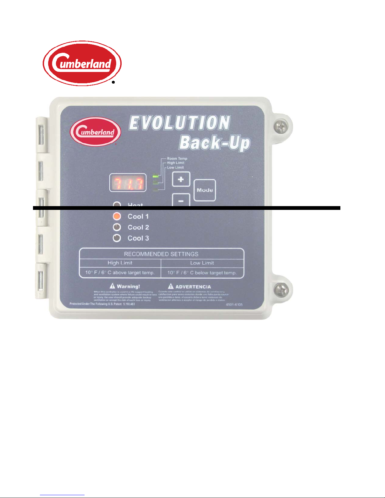
Evolution Back-Up
Cumberland
1004 E. Illinois St.
Assumption, IL 62510
Part No. 4801-5309 Rev 1-15 Owners Manual Evolution Back-Up
CUMBERLAND Assumption, IL 62510 • Phone 217-226-4421 • Fax 217-226-4420
Page 2

Table of Contents
Section Title Page
Ratings and Specifications ............................................................................................................................. 3
1.
2. Warnings ........................................................................................................................................................ 3
3. Introduction to the Evolution Back-Up System ............................................................................................. 4
4. Evolution Back-Up Operating Conditions ..................................................................................................... 4
4.1 Normal Evolution Operation .................................................................................................................. 4
4.2 Emergency Operation ............................................................................................................................. 5
4.3 Override Operation ................................................................................................................................. 5
4.4 Fail-Safe Relay Operation ...................................................................................................................... 5
5. Inlet Operation During Back-up ..................................................................................................................... 5
6. Setting EV-Back-Up Stage Jumpers............................................................................................................... 5
7. Day-to-Day Back-Up Operating Instructions ................................................................................................. 6
7.1 Toggle Sequence of Mode Button .......................................................................................................... 6
7.2 Checking/Adjusting Temperatures, and Settings ................................................................................... 6
8. Set Limits ....................................................................................................................................................... 6
9. Program Mode Parameters ............................................................................................................................. 7
10. Calibrate Sensors ........................................................................................................................................ 7
10.1 Installation .............................................................................................................................................. 8
10.2 Unpacking Components ......................................................................................................................... 8
10.3 Installation Instructions .......................................................................................................................... 8
10.4 Checklist For Setting Up Control of House Temperature ...................................................................... 8
11. Wiring Diagrams ........................................................................................................................................ 9
11.1 Evolution Back-Up Assembly ................................................................................................................ 9
11.2 Wiring the Back-Up Board Sensors and Alarm Connections .............................................................. 10
11.3 Evolution Back-Up Power Trak Override Settings and Wiring ........................................................... 11
11.4 Power Supply Connection .................................................................................................................... 12
11.5 Connecting Local Network & Back-up to the Evolution 3000 ............................................................ 13
12. Temperature vs. Sensor Resistance Table ................................................................................................ 14
13. Error Codes............................................................................................................................................... 15
14. Warranty ................................................................................................................................................... 16
Part No. 4801-5309 rev 1-15 Evolution Back-Up Table of Contents
Page 3
1. Ratings and Specifications
115/230 Volts (Depending on switch position.)
50/60 Hz.
Room Temperature must be between 32F/0C and 122F/50C.
2. Warnings
When this controller is used in a life support heating and ventilation system
where failure could result in loss or injury, the user should provide
adequate back-up, or accept the risk of such loss or injury!
Warning!
Part No. 4801-5309 rev 1-15 Evolution Back-Up 3 of 17
Page 4
g
3. Introduction to the Evolution Back-Up System
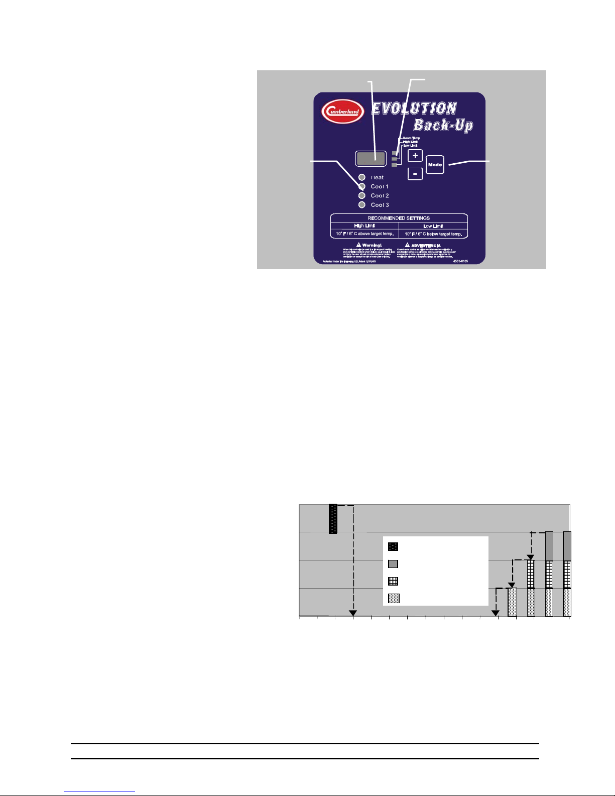
The Evolution system has the
option of containing an integrated
Back-Up System. This Back-Up
System contains 4 stages: 1 Heat
and 3 Cool. This system’s
purpose is to back up the master
controller in the case of failure.
The Back-Up System is a standalone control system. It contains
its own temperature sensors that
react to a High and Low Limit.
This Back-Up System is unlike
any emergency control system on
the market. This system offers a
much higher level of protection.
In addition to being able to
monitor for high and low
temperatures, it also stays in constant communication with the master controller. This communication
allows the Back-Up System to run a minimum ventilation timer on Cool 1 or override the Evolution panel
if certain conditions warrant. The conditions are explained in Section 4. All Back-Up Systems can protect
against a high or low temperature, but only this system can protect against today’s biggest grower concern:
MINIMUM VENTILATION FAILURE!
Back-Up
Indicators
Main Display
e
Sta
®
Display Indicator
Control
Buttons
4. Evolution Back-Up Operating Conditions
As explained above, this is more than your customary Back-Up System. This system contains three
separate modes of operation that are entered depending on the circumstances. These modes are Normal
Operation, Emergency Operation, and Override Operation. These modes will be explained in more detail
below. These modes are entered based on information that it has received, or not received, from the master
controller. No matter what mode of operation the Back-Up System is in, it will always attempt to maintain
the temperature inside the High and Low Limits.
4.1 Normal Evolution Operation
During Normal Operation, the Back-Up System always maintains the temperature between its high and low
limits. It accomplishes this by using its
temperature sensors and its four stage
outputs. If the temperature drops below
the Low Limit, the Heat stage will come
on. That stage will not turn off until it
warms the building at least 2. The
same is true if the temperature goes
above the High Limit however, there
are three levels of cooling stages on the
Back-Up System. The following
example explains the operation of the
stages in relationship to the temperature
and the limits. In this example the Low
Limit is set as 66º F, and the High Limit
is set as 86º F. If the
temperature drops to 66º F, then the HEAT stage turns on. The HEAT stage turns off when the
temperature rises to 68º F (1º above the Low Limit). If the temperature rises to 86º F, then COOL 1 turns
on. If the temperature continues to rise to 87º F (1º above the High Limit), then COOL 2 turns on. If the
temperature rises to 89º F, then COOL 3 turns on. Stages turn off at temperatures as indicated by the
arrows in Graph 1. It is important to note, if COOL 3 turns ‘ON’, COOL 1 will be disabled to insure that
sidewall fans or vent inlets are not operating while the Back-Up system is in ‘Tunnel Vent’ mode.
64 68 72
Graph 1
Cool 1, 2, 3 and Heat
Heat
Cool 3 - Tunnel
Cool 2
Cool 1- Vents
……….
Temperature (ºF)
83
86
85
84
87
88
89
Part No. 4801-5309 rev 1-15 Evolution Back-Up 4 of 17
Page 5
4.2 Emergency Operation
In this mode of operation, the system still maintains the temperature as it does in Normal Operation. In
addition, it will begin running the first cooling stage (Cool 1) on a 5 minute timer. The timer percentage is
determined by the setting in P3 (Emergency Timer Percentage). This mode of operation is entered if
communication is lost between the master controller and the Back-Up System. In this case, the Back-Up
System assumes that the master controller is lost and tries to maintain the minimum ventilation until
someone recognizes the problem. Emergency Operation is indicated by a “LnE” flashing in the display of
the Back-Up System. The alarm relay on the Back-Up System is also engaged in this mode operation.
4.3 Override Operation
In this mode of operation, the system still maintains the temperature as it does in Normal Operation. In
addition, it receives commands from the master controller to turn on certain stages of heating or cooling.
There are many different circumstances that could cause this to happen, in this manual, we will list one of
the most common. For example, if communication were lost inside the EV-3000, the master controller
would be unable to turn the appropriate stages on in the usual way. Therefore, the master controller would
communicate to the Back-Up System and indicate which stages that it is trying to turn on. At this point,
the Back-Up System would obey the command and turn the appropriate stages on. For this mode of
operation to work to its fullest potential, care must be taken to insure that the stage jumpers on the relay
strips match the stage setting in the master controller (Refer to Section 12). Override Operation is
indicated by a “LnO” flashing in the display of the Back-Up System. The alarm relay is also engaged in
this mode of operation.
4.4 Fail-Safe Relay Operation
There are two types of Relay strips used in the Evolution 3000. The Normally Open (NO) strip requires a
signal from the controller board in order to energize a stage of ventilation. Should power be removed from
the EV-3000 the Normally Open Relay strips would not be able to energize a ventilator. On the other hand
the Fail-Safe relay strip would close each of the relays in the strip resulting in energizing the ventilators in
case of a controller power failure. Each of the relay strips contains four relays for controlling four stages.
In the EV-3000 there are a total of four relay strips, three will be N.O. and one will be a Fail-Safe. The
operator must insure that the Fail Safe relay strip is connected only to stages that should be turned on in
case of a controller failure. See the EV-3000 Owners manual Part No. 4801-5307 for a physical
description of the relay strips. It is not recommended to place heating equipment on Fail-Safe stages.
5. Inlet Operation During Back-up
The EV-Back-Up contains a relay that can operate the Vents
and/or Tunnel during Back-up operation of the EV-3000.
The Inlets will automatically open during back-up.
Cool 1 controls Vents Inlet. Cool 3 controls Tunnel Inlets.
When Cool 1 and Cool 3 are not set, Back-up reverts to Normal
operation.
Stage Relay
Stage
Jumpers
COOL 3
COOL 2
COOL 1
HEAT
6. Setting EV-Back-Up Stage Jumpers
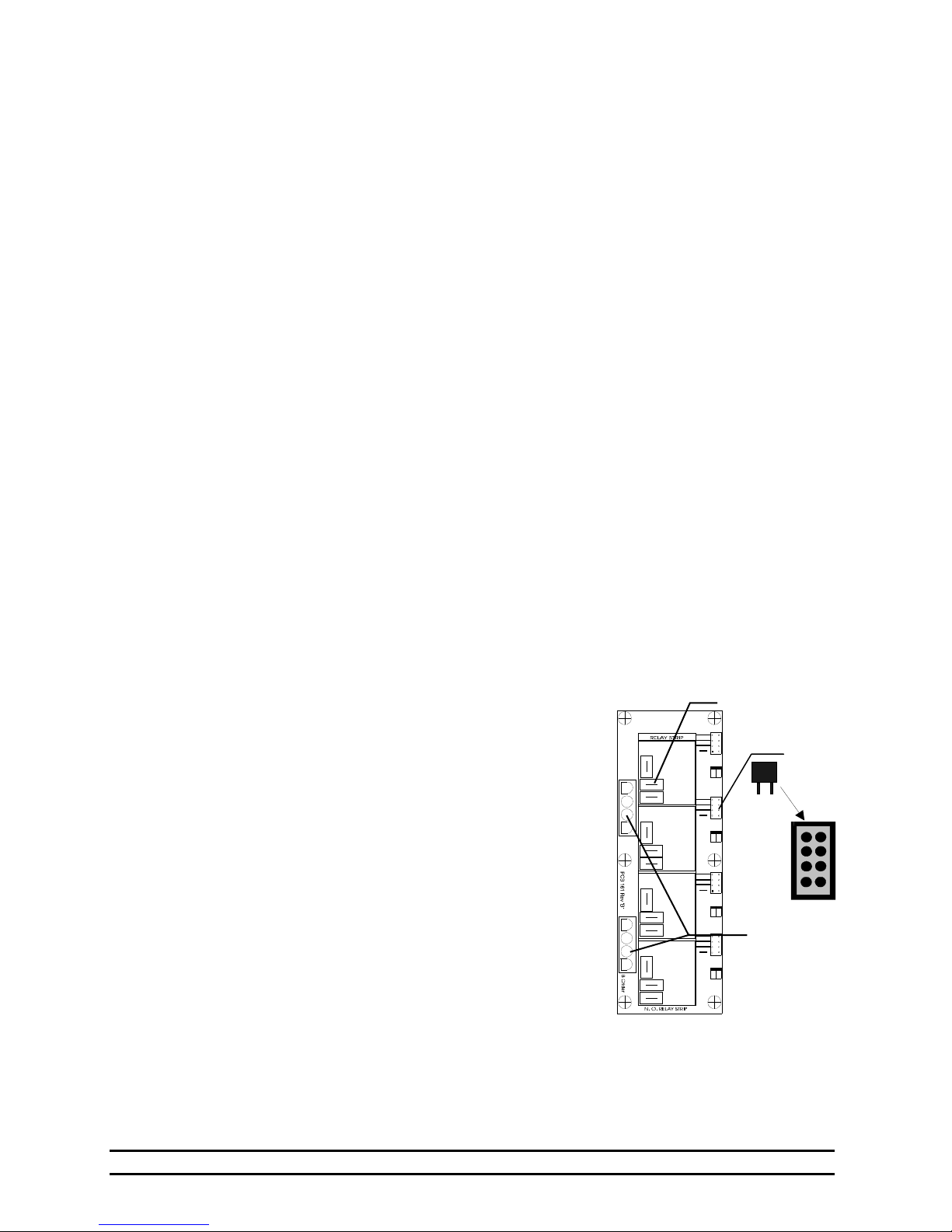
Pictured at the right is a Stage Relay Board consisting of four
stage relays and the associated stage jumper for each stage relay.
The stage jumpers are labeled COOL 1, COOL 2, COOL 3 and
HEAT. Location of the jumper places the stage in one of these
four modes, or if the jumper is not inserted, the stage is not
placed on Back-Up. The jumpers should be placed based on the
operation of stage equipment and should be the same as assigned
in the EV-3000 Controller. Jumpers are placed according the
following table:
Part No. 4801-5309 rev 1-15 Evolution Back-Up 5 of 17
Stage Harness
connector
cables to
Terminal Block
STAGE RELAY BOARD
Page 6
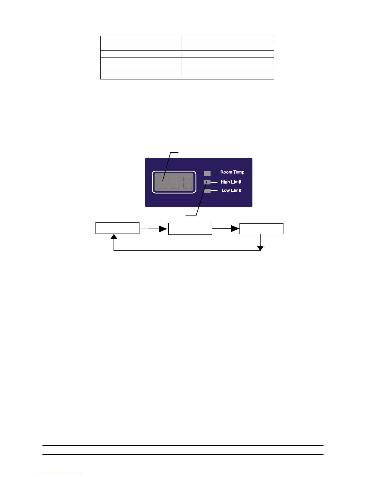
Type of Stage Operation Jumper Assignment
Cool Negative Fan COOL 1
Cool Negative Tunnel Fan COOL 2
Cool Tunnel Fan COOL 3
Heat Stage HEAT
Stage not on Back-Up No Jumper Installed
Additional information can be found in the Evolution 3000 Owners Manual, Part Number 4801-5307.
7. Day-to-Day Back-Up Operating Instructions
7.1 Toggle Sequence of Mode Button
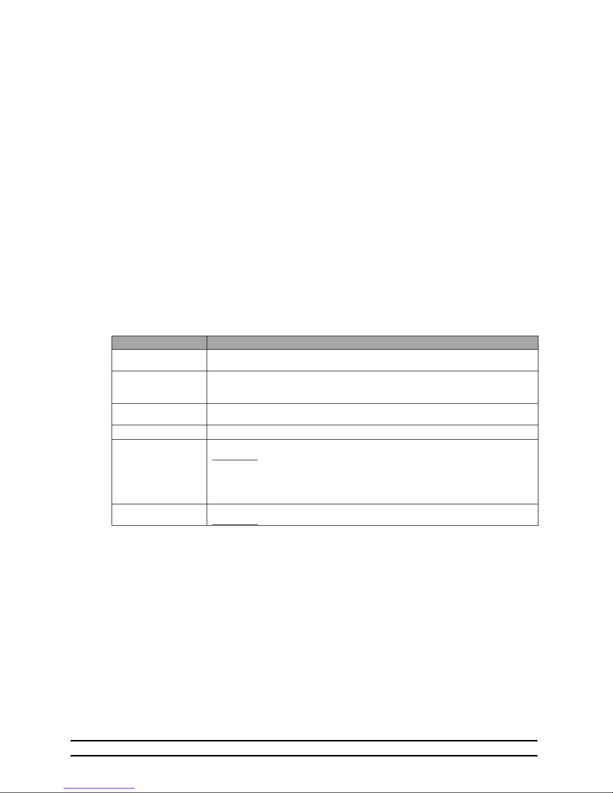
Continuously pressing the Mode button cycles the display through the parameter sequence as illustrated
below. The parameter data is shown in the display.
Room Temp
Display LEDs
Main Display
High Limit
Low Limit
7.2 Checking/Adjusting Temperatures, and Settings
When you press the Mode button, watch the green LED’s beside the main display. Whichever LED is lit is
the parameter you are viewing: “Room Temp”, “High Limit”, and “Low Limit” values. Note: To adjust
these parameters, press the Mode button until you see the parameter you want to adjust, then use the +
button to increase the value, and the - button to decrease the value.
Room Temperature - The average of the sensors located inside the house.
High Limit - The temperature inside the house at which the controller will turn on the first Evolution
Back-Up cooling stage.
Low Limit - The temperature inside the house at which the controller will turn on the first Evolution
heating stage.
8. Set Limits
The EV-3000 Back-Up System requires setting of a High Limit and a Low Limit at which cool/heat stages
will turn on. To determine where to set the High Limit and the Low Limit, first decide on a target
temperature of the house. This is usually the target temperature of the primary controller. Then set the
High Limit to a temperature several degrees above the desired target temperature. Set the Low Limit to a
temperature several degrees below the desired target temperature. Note: It is recommended that the
High Limit be at least 10º above the room’s target temperature and that the Low Limit be 10º below
the room’s target temperature.
Part No. 4801-5309 rev 1-15 Evolution Back-Up 6 of 17
Page 7
To Set High Limit:
1. Press the “Mode” button to select the High Limit Indicator.
2. Press the ”+” and ”–“ buttons to enter the value of the High Limit.
3. Setting Complete.
To Set Low Limit:
1. Press the “Mode” button to select the Low Limit Indicator.
2. Press the + and – button to enter the value of the Low Limit.
3. Setting Complete.
9. Program Mode Parameters
Settings that are usually set up once per growout, or maybe even just for summer or winter are referred to
as program parameters and are accessed by taking the controller to program mode. To get to program
mode, press and hold the “Mode” button for five seconds. When the controller has entered program mode,
the main display will flash between “P1” and the value of this parameter.
The “P1” is known as a parameter number. All the program items for the controller have a parameter
number assigned to them. The numbers are listed in the table “Program Mode Parameters” below with a
short description of each parameter. When in program mode, you change the value of certain parameters
by using the + and - buttons as needed. When you have finished with the current setting, press the “Mode”
button to move to the next parameter. The program mode parameters for the Evolution Back-Up are
shown in Table 1.
Table 1. Program Mode Parameters
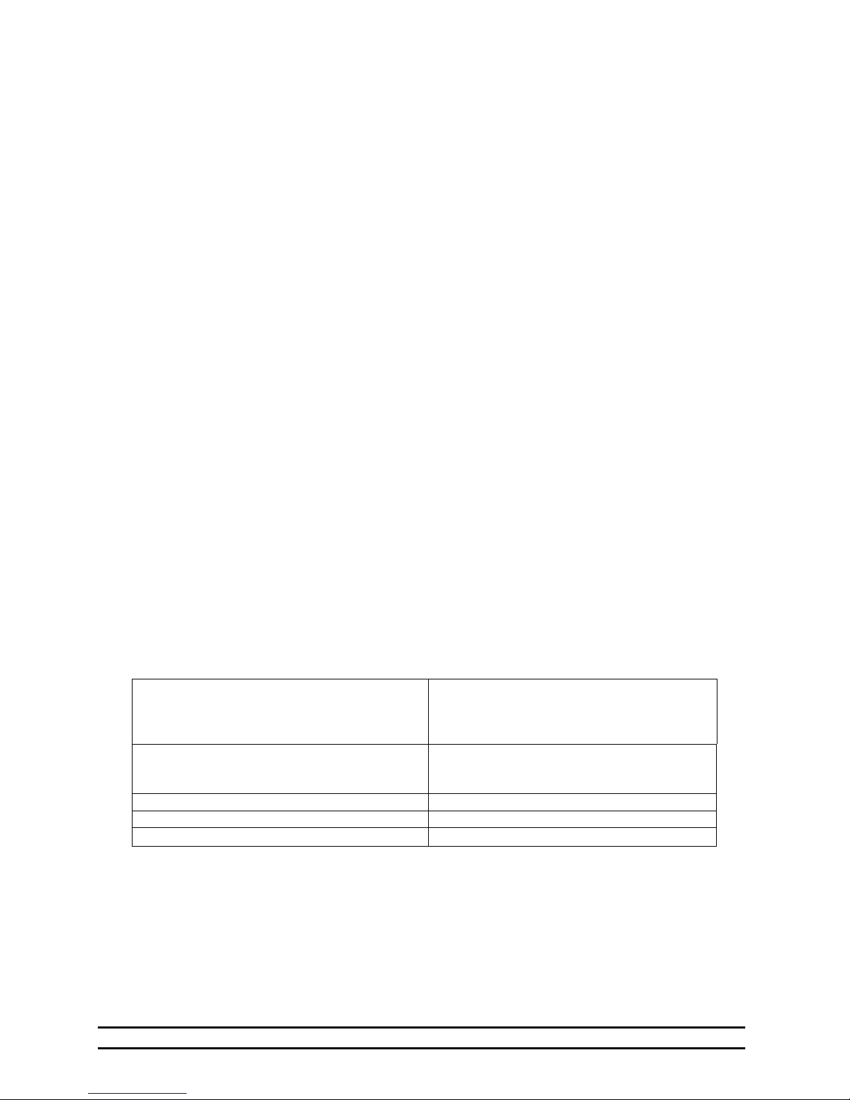
Parameter Description
P1
P2
P3
P41
PS1
PS2
This selects either English (OFF = Fahrenheit) or Metric (ON = Celsius) temperature
units.
Determines if an alarm is sent on a Back-Up condition. (ON = Alarm On, OFF = Alarm
OFF) An alarm will be generated on an error condition even if P2 is set to OFF. See
Section 13.
Emergency Timer Percentage. (0% to 100%). This determines the percentage that
COOL 1 will be run in an Emergency condition.
This is the software version number. Not Changeable.
This is the calibration temperature for Sensor 1.
Instructions:
independent temperature measuring device to measure the temperature at Sensor 1
location. With PS1 selected, use the + and – buttons to set the calibration temperature
to the thermometer reading.
This is the calibration temperature for Sensor 2.
Instructions:
10. Calibrate Sensors
The temperature sensors should be calibrated to ensure accurate temperature detection. To calibrate the
sensors an independent temperature measurement is required such as a thermometer or thermocouple.
1. Place a thermometer inside the house at the location of each sensor. Allow a few minutes for the
temperature to stabilize.
2. Take readings from the thermometers located at Sensor 1 and Sensor 2.
3. Use the Program Mode to set calibrations of Sensor 1 and Sensor 2 (Refer to Table 1).
With the controller operating, use a digital thermometer or similar
Same as Sensor 1 except substitute PS2 for PS1 in the instructions above.
Part No. 4801-5309 rev 1-15 Evolution Back-Up 7 of 17
Page 8
10.1 Installation
10.2 Unpacking Components
Unpack the system, and check that all components are present. Locate the required tools.
1 Evolution 3000 Back-Up
1 Temperature Sensor
1 Manual
10.3 Installation Instructions
1. Hang Evolution Back-Up with four screws and the plastic mounting brackets included.
2. Make sure all power supplies are disconnected before breaking any wires, or reaching into the
enclosure.
3. Locate the sensor connections. Refer to Wiring Diagrams, Schematics, etc.
4. For the Back-Up, run sensors out to locations inside the house. Be sure that the sensors are in a safe
location, free from any extreme temperature influences (direct sunlight, water, etc.) Use care when
securing sensor wires so that you do not cut the wire. Any short or break in the wire will cause
improper sensor operation.
5. Connect each sensor to its appropriate terminals inside the enclosure. See Section 11.2.
6. Wire the power supply. See Section 11.4.
7. Wire the Back-Up to the EV-3000. See Wiring Diagrams at the back of this manual.
8. Wire the Local Network connection.
9. Connect the PowerTrak to the Overrides. See Diagram in Section 11.3.
10. Close the Back-Up and tighten the two screws in th e lid to secure the unit shut.
Tools Required:
Mini Screwdriver
Wire Strippers
Standard Screwdriver
10.4 Checklist For Setting Up Control of House Temperature
Please read and follow the Installation instructions on the followin g pages. Refer to the following
checklist as an aid in setting the Evolution Back-Up controller.
1. Physically install the controller, temperature
sensors, and wires leading from the output
stages to cooling and/or heat equipment or to
a control panel.
2. Verify the Back-Up jumpers on the Stage
Block. Set Heat/Cooling Stage options.
3. Install power to controller. Refer to Section 11.4.
4. Set High Limit & Low Limit Refer to Section 8, Set Limits.
5. Calibrate Sensors Refer to Section 10, Calibrate Sensors
Refer to Section 11, Wiring Diagrams
Refer to the Evolution 3000 Owners Manual,
Part Number 4801-5307 and to Section 6 of
this manual,
Part No. 4801-5309 rev 1-15 Evolution Back-Up 8 of 17
Page 9
11. Wiring Diagrams
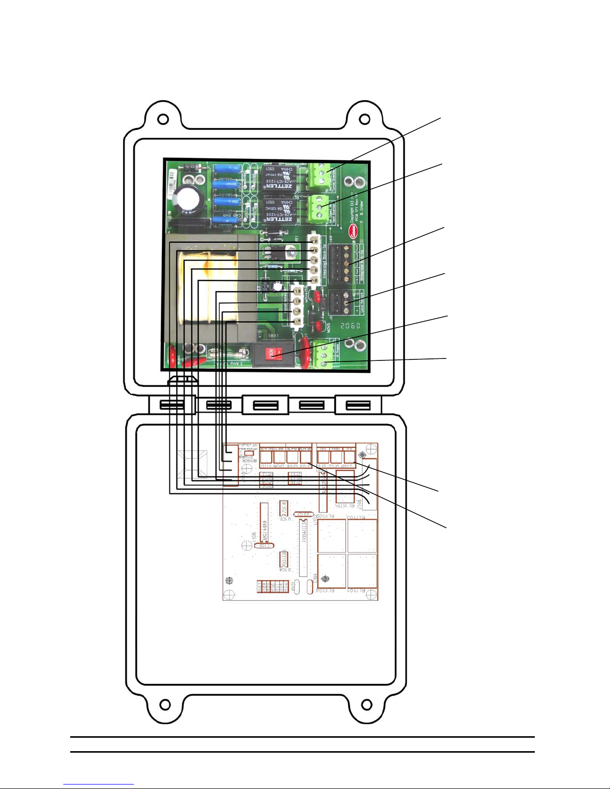
11.1 Evolution Back-Up Assembly
Tunnel
Override
Settings
Vent
Override
Settings
Backup
Connections
to Evolution
Local Network
Connections
Voltage Selector
Switch
Power Supply
Connections
Alarm
Connections
Sensor
Connections
Part No. 4801-5309 rev 1-15 Evolution Back-Up 9 of 17
Page 10
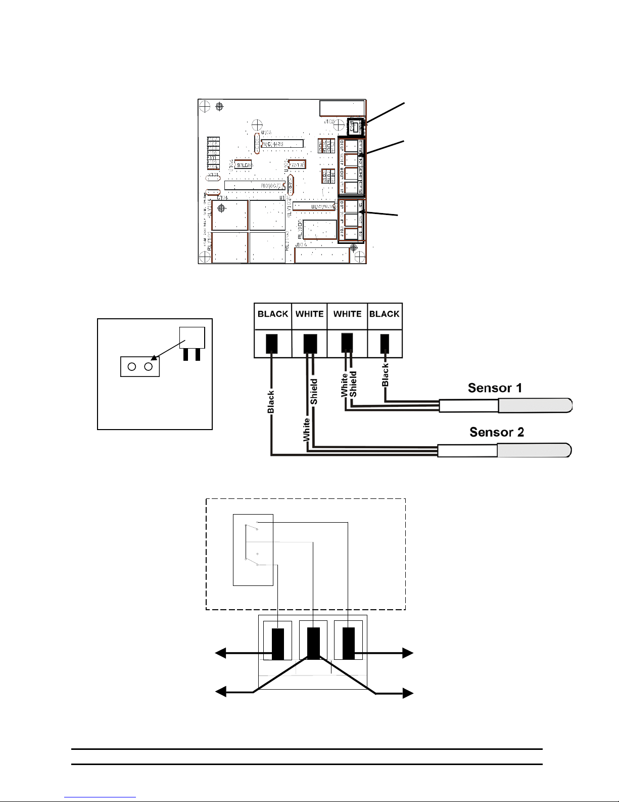
11.2 Wiring the Back-Up Board Sensors and Alarm Connections
Jumper Connection to
Inset A
Enable Sensor 2
Sensor 2
Enabled
Installed – Enabled
Vacant – Disabled
Jumper
Back-Up Alarm Connection
Contacts
For a Series
Alarm Connection
Inset B
Sensor 1 & 2 Connections
Inset C
Internal Wiring
Switch
NO COM NC
BACK-UP ALARM
Inset A
Inset B
Inset C
NOTE: Tape Shields to
Prevent Damage.
For a Parallel
Alarm Connection
Part No. 4801-5309 rev 1-15 Evolution Back-Up 10 of 17
Page 11
V
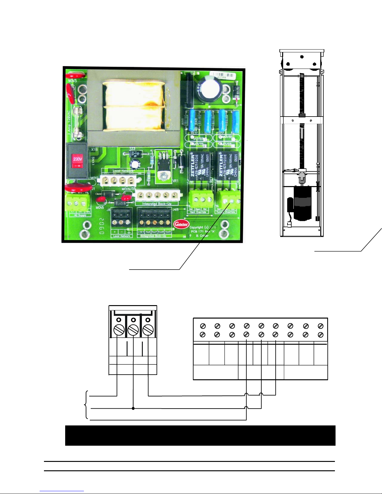
11.3 Evolution Back-Up Power Trak Override Settings and Wiring
Evolution Back-Up Circuit Board
Tunnel Override
Vents Override
Inset A
Vent Override
Inset B
PowerTrak
Cont
PT
Hot
Open
ent Override
PT
Hot
UPPER
AUX
SWITCH
IN
HO
COM
LOWER
OPEN
CLOSE
CONTROLLER AC IN
To
EV-3000
Com
Open
Close
NOTE: If curtain is setup to pull curtain up to open, then reverse wires connected
to 'Open' and 'Close' terminals.
PowerTrak
Inset A
OU
GND
NEUT.
HO
Part No. 4801-5309 rev 1-15 Evolution Back-Up 11 of 17
Page 12
Expansion Module
N
N
N
N
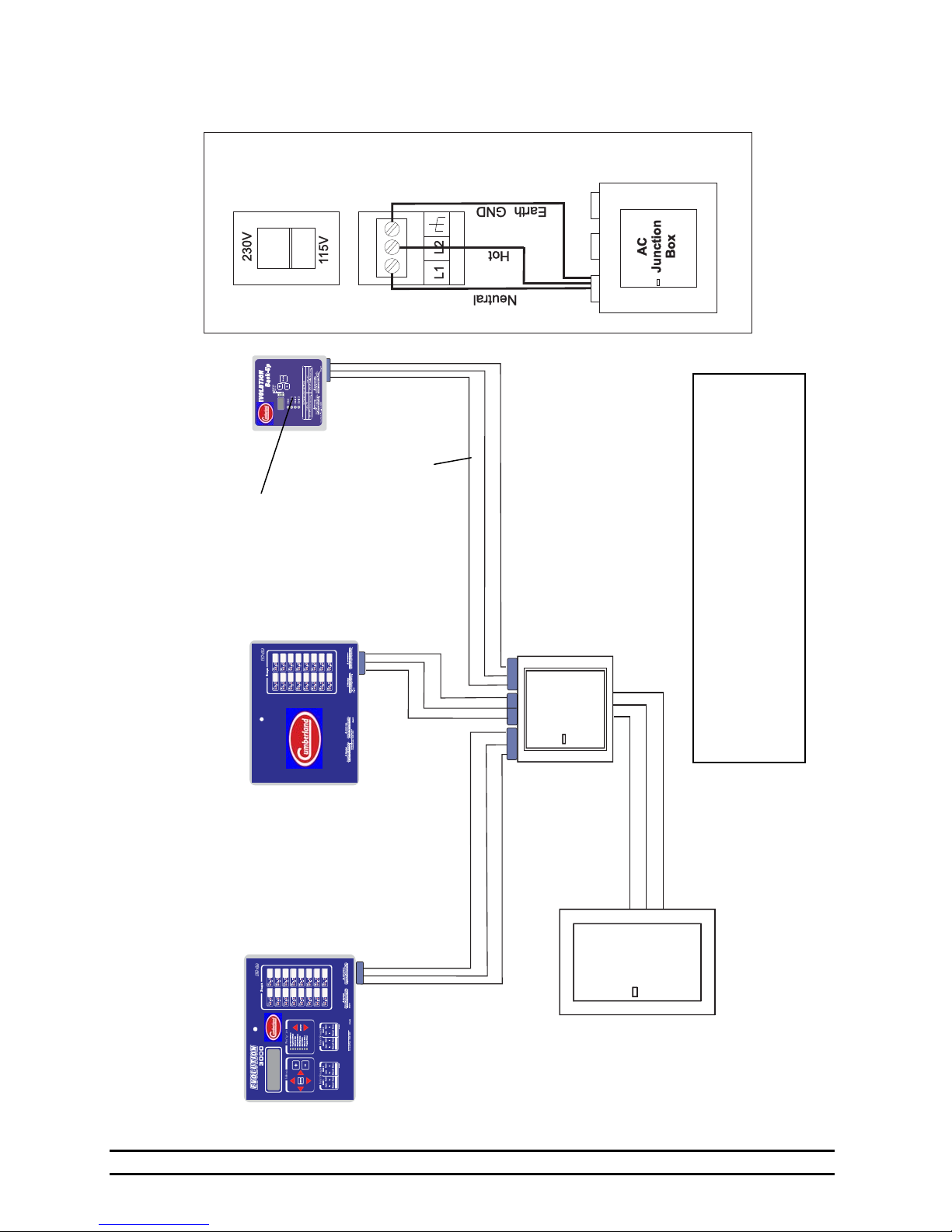
11.4 Power Supply Connection
INSET A
Evolution
Inset A
Evolution 3000 16
NOTE: Controllers shipped from HHI set to
240V. Set slide switch of power selector to
voltage of power supply connected!
Cabinet
Back-up
171)
on PCB
(AC input
cabinet to a common AC
NOTE: Run power cables
junction box. Do NOT run
including ground from each
Stage
Cabinet
Evolution 3000
Hot
between cabinets.
eutral
External GND
AC power and ground
eutral
Hot
External GND
Hot
eutral
External GND
AC
Junction
Box
Hot
eutral
External GND
Box
Breaker
IMPORTANT!
Protection
From Main Controller For Added
Back-up Can Be On A Separate Breaker
Part No. 4801-5309 rev 1-15 Evolution Back-Up 12 of 17
Page 13
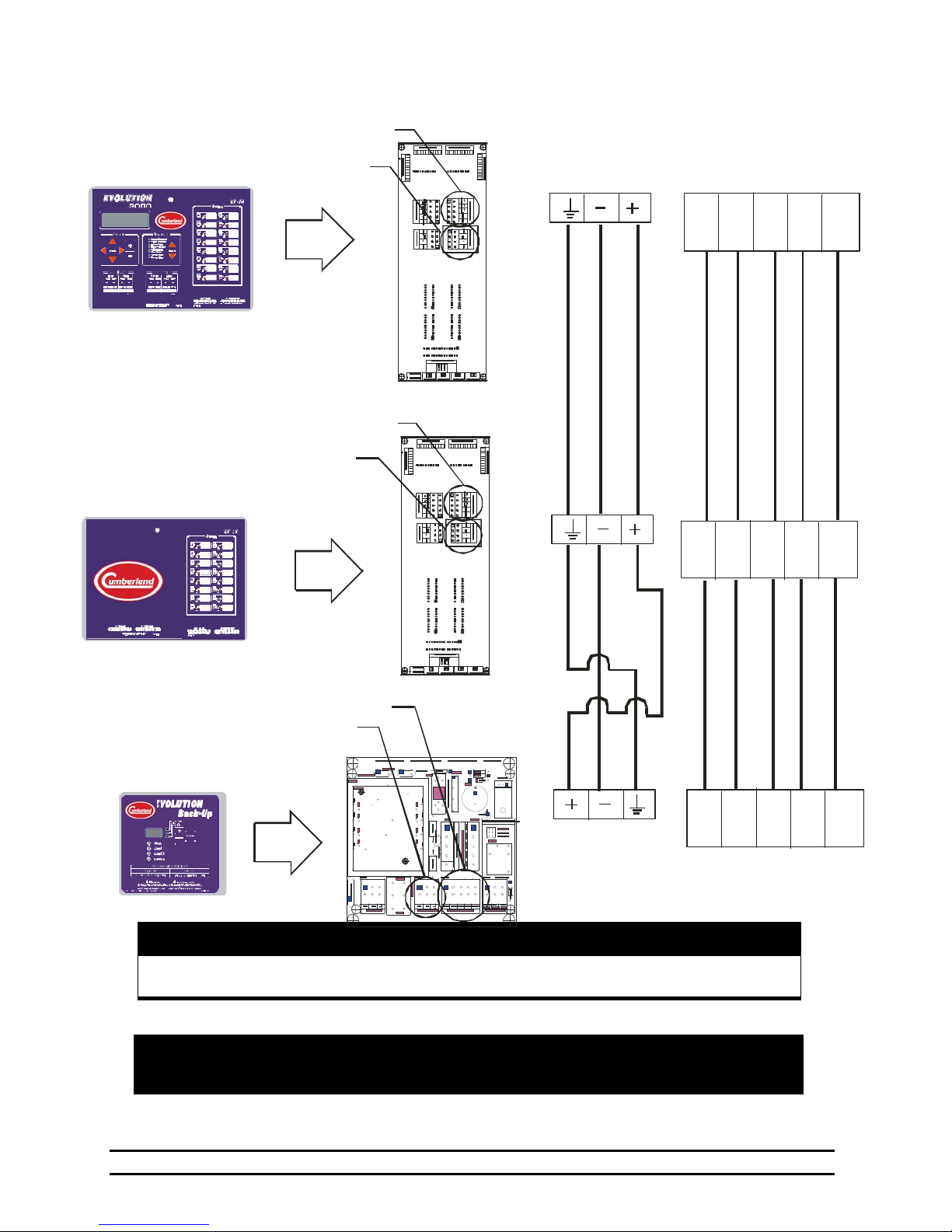
11.5 Connecting Local Network & Back-up to the Evolution 3000
Evolution 3000
Cabinet
Back-up
Local Network
PCB 168
Local Net
Evolution 3000 16 Stage
Expansion Module
Local Network
Back-up
PCB 168
d
l
e
i
n
h
e
S
e
/
r
e
t
G
i
h
W
Local Net
d
n
e
e
r
G
l
e
i
h
S
/
e
t
i
h
W
Evolut ion
Backup
Local net work
Back-up
PCB 171
Local Net
NOTE: Harness to connect Local Network and Back-up together are connected &
Tape Shield To Prevent Damage!
Warning!
Harness In Expansion & Backup
included in the Back-up and 16 Stage Expansion units.
Back-up
1
T
V
2
1
k
c
a
l
B
d
e
R
L
A
O
E
O
H
C
e
g
n
a
r
O
e
t
i
h
W
k
c
a
l
B
3
2
L
L
O
O
O
O
C
C
n
e
e
r
G
Back-up
1
T
V
2
1
k
c
a
l
B
d
e
R
L
A
O
E
O
H
C
e
g
n
a
r
O
e
t
i
h
W
k
c
a
l
B
3
2
L
L
O
O
O
O
C
C
n
e
e
r
G
Back-up
1
T
V
2
1
L
A
O
E
O
H
C
3
2
L
L
O
O
O
O
C
C
Part No. 4801-5309 rev 1-15 Evolution Back-Up 13 of 17
Page 14
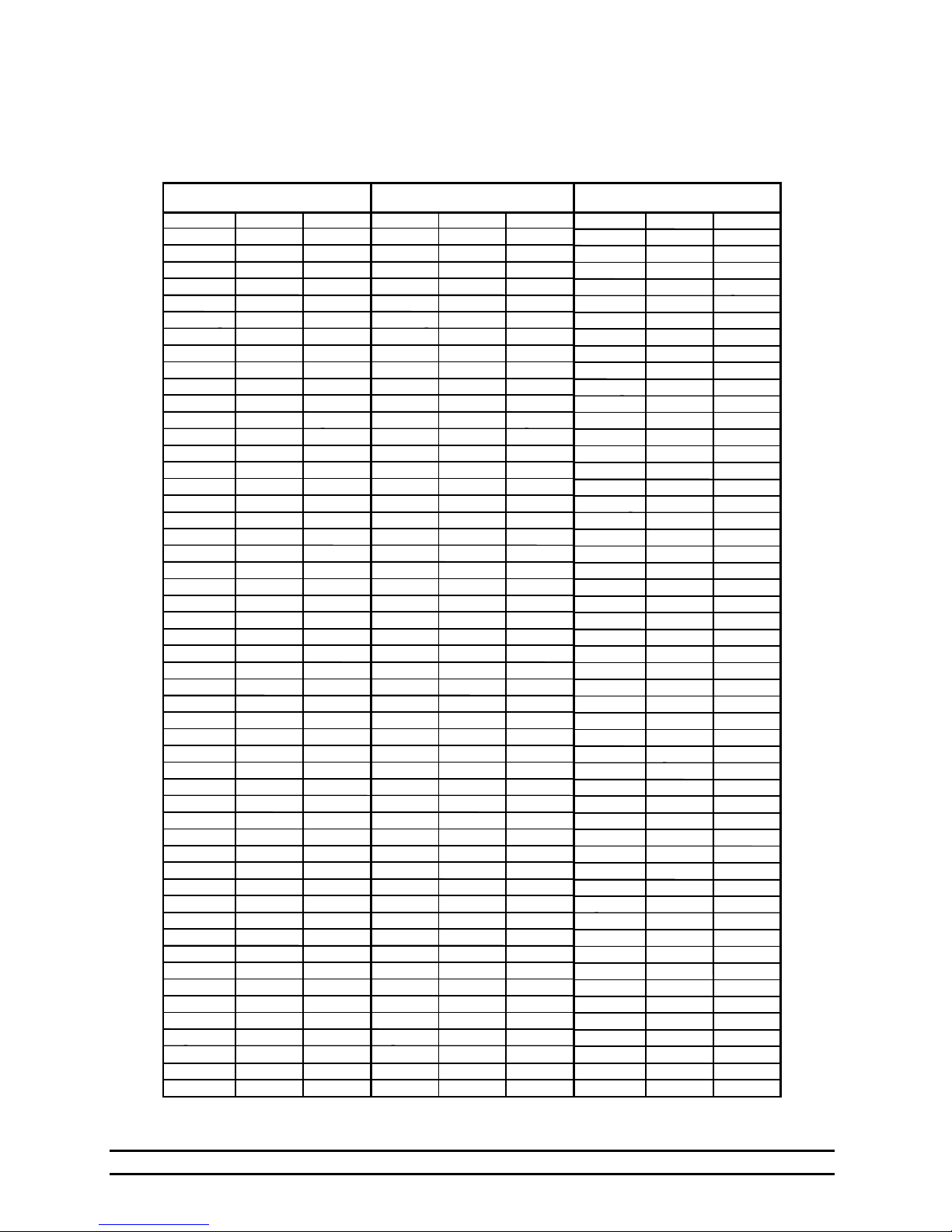
12. Temperature vs. Sensor Resistance Table
The following chart gives the resistance when measured between the white and black sensor wires at a given
temperature. To check a sensor, first know the temperature in the area, then, use a multi-meter to check the
resistance.
Resistance Temp Temp Resistance Temp Temp Resistance Temp Temp
Kohms (F) (C) Kohms (F) (C) Kohms (F) (C)
32.654 32 0 15.714 59 15 8.59 83.3 28.5
32.158 32.5 0.3 15.568 59.4 15.2 8.517 83.7 28.7
31.671 33.1 0.6 15.353 59.9 15.5 8.408 84 28.9
31.191 33.6 0.9 15.211 60.3 15.7 8.336 84.6 29.2
30.72 34.2 1.2 15.001 60.8 16 8.23 85.1 29.5
30.257 34.7 1.5 14.863 61.2 16.2 8.125 85.6 29.8
29.802 35.2 1.8 14.658 61.7 16.5 8.056 86 30
29.355 35.8 2.1 14.457
28.915 36.3 2.4 14.325 62.6 17 7.853 87.1 30.6
28.482 36.9 2.7 14.128 63.1 17.3 7.787 87.4 30.8
28.057 37.4 3 13.999 63.5 17.5 7.689 88 31.1
27.777 37.8 3.2 13.808 64 17.8 7.592 88.5 31.4
27.363 38.3 3.5 13.682 64.4 18 7.496 89.1 31.7
26.957 38.8 3.8 13.496 64.9 18.3 7.433 89.4 31.9
26.557 39.4 4.1 13.373 65.3 18.5 7.34 90 32.2
26.164 39.9 4.4 13.192 65.8 18.8 7.248 90.5 32.5
25.777 40.5 4.7 13.073 66.2 19 7.157 91 32.8
25.523 40.8 4.9 12.896 66.7 19.3 7.098 91.4 33
25.147 41.4 5.2 12.779 67.1 19.5 7.009 91.9 33.3
24.777 41.9 5.5 12.607 67.6 19.8 6.922 92.5 33.6
24.413 42.4 5.8 12.493 68 20 6.836 93 33.9
24.055 43 6.1 12.325 68.5 20.3 6.779 93.4 34.1
23.82 43.3 6.3 12.215 68.9 20.5 6.695 93.9 34.4
23.472 43.9 6.6 12.051 69.4 20.8 6.612 94.5 34.7
23.13 44.4 6.9 11.943 69.8 21 6.531 95 35
22.793 45 7.2 11.783 70.3 21.3 6.45 95.5 35.3
22.572 45.3 7.4 11.678 70.7 21.5 6.371 96.1 35.6
22.244 45.9 7.7 11.522 71.2 21.8 6.319 96.4 35.8
21.922 46.4 8 11.42 71.6 22 6.241 97 36.1
21.71 46.8 8.2 11.268 72.1 22.3 6.165 97.5 36.4
21.397 47.3 8.5 11.168 72.5 22.5 6.089 98.1 36.7
21.088 47.8 8.8 11.02 73 22.8 6.015 98.6 37
20.886 48.2 9 10.874 73.6 23.1 5.941 99.1 37.3
20.586 48.7 9.3 10.778 73.9 23.3 5.869 99.7 37.6
20.29 49.3 9.6 10.636 74.5 23.6 5.798 100.2 37.9
20.096 49.6 9.8 10.542 74.8 23.8 5.728 100.8 38.2
19.809 50.2 10.1 10.404 75.4 24.1 5.658 101.3 38.5
19.526 50.7 10.4 10.312 75.7 24.3 5.59 101.8 38.8
19.34 51.1 10.6 10.177 76.3 24.6 5.522 102.4 39.1
19.065 51.6 10.9 10.088 76.6 24.8 5.456 102.9 39.4
18.884 52 11.1 9.956 77.2 25.1 5.39 103.4 39.7
18.616 52.5 11.4 9.869 77.5 25.3 5.326 104 40
18.352 53.1 11.7 9.741 78.1 25.6 5.262 104.5 40.3
18.179 53.4 11.9 9.614 78.6 25.9 5.199 105.1 40.6
17.503 54.9 12.7 9.53 79 26.1 5.137 105.6 40.9
17.339 55.2 12.9 9.407 79.5 26.4 5.076 106.2 41.2
17.095 55.8 13.2 9.325 79.9 26.6 4.995 106.9 41.6
16.856 56.3 13.5 9.205 80.4 26.9 4.936 107.4 41.9
16.698 56.7 13.7 9.086 81 27.2 4.877 108 42.2
16.465 57.2 14 9.007 81.3 27.4 4.82 108.5 42.5
16.312 57.6 14.2 8.891 81.9 27.7 4.763 109 42.8
16.085 58.1 14.5 8.815 82.2 27.9 4.688 109.8 43.2
15.935 58.5 14.7 8.702 82.8 28.2
62.2 16.8 7.954 86.5 30.3
Part No. 4801-5309 rev 1-15 Evolution Back-Up 14 of 17
Page 15
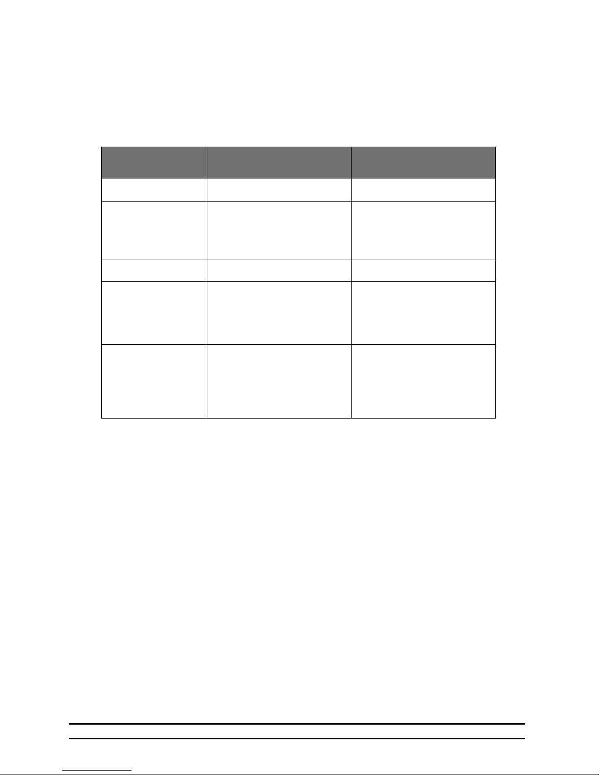
13. Error Codes
If your controller is displaying an “E1” or “E2”, etc. the controller has recorded an error.
The controller records errors based on sensor reading and the communications links. When any of these
errors occur an alarm will be generated.
Error Codes for the Evolution Back-Up System
Error Code Description Explanation
E1
E2
E3
LnE
LnO
Sensor 1 Error
Sensor 2 Error Usually indicates a shorted sensor
Sensor 1 and Sensor 2 Sensors 1 and 2 both shorted.
Local Network Error The Back-Up has lost
Local Network Override Error The Master Controller has lost
Usually indicates a shorted sensor
wire. Check sensor resistance.
wire. Check sensor resistance.
Note: If Sensor 2 is switched
OFF, then this error code is not
active.
Communications with the Master
Controller. NOTE: During this
condition the Back-Up will run
Cool 1 on a 5 minute timer.
communications with one or
more of the StageUnits (PCB
168) connected to it. In this
condition the Back-Up takes
control over the stages.
Part No. 4801-5309 rev 1-15 Evolution Back-Up 15 of 17
Page 16
Limited Warranty
14. Warranty
The GSI Group, LLC. (“GSI”) warrants products which it manufactures to be free of defects in materials and
workmanship under normal usage and conditions for a period of 12 months after sale to the original end-user or if
a foreign sale, 14 months from arrival at port of discharge, whichever is earlier. The end-user’s sole remedy (and
GSI’s only obligation) is to repair or replace, at GSI’s option and expense, products that in GSI’s judgment,
contain a material defect in materials or workmanship. Expenses incurred by or on behalf of the end-user without
prior written authorization from the GSI Warranty Group shall be the sole responsibility of the end-user.
Warranty Extensions: The Limited Warranty period is extended for the following products:
Product Warranty Period
Performer Series Direct Drive
AP Fans and
Flooring
AP/Cumberland Flex-Flo/Pan Feeding Systems 2 Years
Cumberland
Feeding/Watering
Systems
Grain Systems Grain Bin Structural Design 5 Years
Grain Systems
Farm Fans
Zimmerman
GSI further warrants that the frame, basket and excluding all auger and auger drive components of the portable
and tower dyer shall be free from defects in materials for a period of time beginning on the twelth (12
from the date of purchase and continuing until the sixtieth (60
warranty period). During the extended warranty period, GSI will replace the frame or basket components that
prove to be defective under normal conditions of use without charge, excluding the labor, transportation, and/or
shipping costs incurred in the performance of this extended warranty.
Feeder System Pan Assemblies 5 Years **
Feed Tubes (1.75" & 2.00") 10 Years *
Portable & Tower Dryer Frames
and Internal Infrastructure †
Fan Motor
All Fiberglass Housings Lifetime
All Fiberglass Propellers Lifetime
Centerless Augers 10 Years *
Watering Nipples 10 Years *
Portable & Tower Dryers 2 Years
3 Years
5 Years
th
) month from the date of purchase (extended
* Warranty prorated from list price:
0 to 3 years – no cost to end-user
3 to 5 years – end-user pays 25%
5 to 7 years – end-user pays 50%
7 to 10 years – end user pays 75%
** Warranty prorated from list price:
0 to 3 years – no cost to end-user
3 to 5 years – end-user pays 50%
† Motors, burner components and
moving parts not included. Portable
Dryer screens included. Tower Dryer
screens not included.
th
) month
Conditions and Limitations:
THERE ARE NO WARRANTIES THAT EXTEND BEYOND THE LIMITED WARRANTY DESCRIPT ION SET
FORTH ABOVE. SPECIFICALLY, GSI MAKES NO FURTHER WARRANTY OF ANY KIND, EXPRESS OR
IMPLIED, INCLUDING, WITHOUT LIMITATION, WARRANTIES OF MERCHANTABILITY OR FITNESS FOR A
PARTICULAR PURPOSE OR USE IN CONNECTION WITH: (i) PRODUCT MANUFACTURED OR SOLD BY
GSI OR (ii) ANY ADVICE, INSTRUCTION, RECOMMENDATION OR SUGGESTION PROVIDED BY AN
AGENT, REPRESENTATIVE OR EMPLOYEE OF GSI REGARDING OR RELATED TO THE
CONFIGURATION, INSTALLATION, LAYOUT, SUITABILITY FOR A PARTICULAR PURPOSE, OR DESIGN
OF SUCH PRODUCTS.
GSI shall not be liable for any direct, indirect, incidental or consequential damages, including, without limitation,
loss of anticipated profits or benefits. The sole and exclusive remedy is set forth in the Limited Warranty, which
shall not exceed the amount paid for the product purchased. This warranty is not transferable and applies only
to the original end-user. GSI shall have no obligation or responsibility for any representations or warranties
made by or on behalf of any dealer, agent or distributor.
GSI assumes no responsibility for claims resulting from construction defects or unauthorized modifications to
products which it manufactured. Modifications to products not specifically delineated in the manual
accompanying the equipment at initial sale will void the Limited Warranty.
This Limited Warranty shall not extend to products or parts which have been damaged by negligent use,
misuse, alteration, accident or which have been improperly/inadequately maintained. This Limited Warranty
extends solely to products manufactured by GSI.
Prior to installation, the end-user has the responsibility to comply with federal, state and local codes which apply to
the location and installation of products manufactured or sold by GSI.
Part No. 4801-5309 rev 1-15 Evolution Back-Up 16 of 17
Page 17

Part No. 4801-5309 rev 1-15 Evolution Back-Up 17 of 17
 Loading...