

Cumberland Evolution 3000, Evolution 3001, Evolution 1200 Series, Evolution EV-1200-08-00, Evolution EV-1200-08-01 Owner's Manual
...Page 1
Evolution 3000 and 3001
Environmental Controller
Cumberland
Date: 05-18-15 1004 E. Illinois St.
Assumption, IL 62510
Controller Software Version V0.37
Part No. 4801-5307 Rev 2-15 Owners Manual Evolution 3000 and 3001
CUMBERLAND Assumption, IL 62510 • Phone 217-226-4421 • Fax 217-226-4420
Page 2

Table of Contents
Section Title Page
1. Warranty ........................................................................................................................................................4
2. Warnings ........................................................................................................................................................5
3. Ratings and Specifications .............................................................................................................................5
4. Introduction ....................................................................................................................................................6
5. Evolution Front Panel ....................................................................................................................................6
5.1 Navigator Panel .......................................................................................................................................8
5.2 Editor Panel ............................................................................................................................................8
5.3 Main Display Contrast ............................................................................................................................9
5.4 Inlet Stages ..............................................................................................................................................9
5.5 Status Display .......................................................................................................................................10
5.6 Stage Switch ..........................................................................................................................................10
5.7 Locks .....................................................................................................................................................10
6. Viewing Navigator Status Screens ...............................................................................................................11
6.1 Current Conditions ................................................................................................................................11
6.2 Target Conditions..................................................................................................................................12
6.2.1 Target Conditions - Standard Screen With Optimum Mode OFF .................................................12
6.2.2 Target Conditions – Optimum Screen With Optimum Mode ON .................................................13
6.3 Minimum Vent ......................................................................................................................................14
6.4 Stage Conditions ...................................................................................................................................15
6.4.1 Inlet Conditions .............................................................................................................................15
6.4.2 On/Off Stages ................................................................................................................................16
6.4.3 Natural Ventilation Stages ............................................................................................................16
6.4.4 Variable Stages .............................................................................................................................17
6.5 Historical Data ......................................................................................................................................17
6.5.1 Room Temperature .......................................................................................................................17
6.5.2 Humidity #1 (Room) & Humidity #2 (Cooler) .............................................................................18
6.5.3 Water Usage (#1 or #2) .................................................................................................................18
6.5.4 Ventilation Mode ..........................................................................................................................18
6.5.5 Feed History ..................................................................................................................................19
6.5.6 Belt Run Times .............................................................................................................................19
6.5.7 Stage Run Times ...........................................................................................................................19
6.5.8 Power Track Run Times................................................................................................................19
6.5.9 Alarm Log .....................................................................................................................................20
6.5.10 Cooler Temp .................................................................................................................................20
6.6 Back-Up Status .....................................................................................................................................20
6.7 Alarm Status ..........................................................................................................................................21
6.7.1 High Temperature Alarm Details ..................................................................................................22
6.7.2 Low Temperature Alarm Details ...................................................................................................23
6.7.3 Tunnel Vent Alarm Details ...........................................................................................................23
6.8 Network Status ......................................................................................................................................24
6.9 Program Set-Up ....................................................................................................................................24
7. Setting Programming Functions ...................................................................................................................25
7.1 General Settings ....................................................................................................................................25
7.2 Temperature Sensors .............................................................................................................................25
7.3 Feed Level Sensors ...............................................................................................................................26
7.4 Ventilation Inlets ...................................................................................................................................26
7.5 Natural Ventilation ................................................................................................................................27
7.6 Growout Curve ......................................................................................................................................28
7.6.1 Growout Curve With Optimum Mode OFF ..................................................................................28
7.6.2 Growout Curve With Optimum Mode ON ....................................................................................30
7.7 Tunnel Ventilation ................................................................................................................................33
7.8 ON/OFF Stages ................................................................................................ ................................ .....34
7.8.1 On/Off Stage Details .....................................................................................................................35
7.9 Variable Stage Outputs .........................................................................................................................35
Part No. 4801-5307 Rev 2-15 Evolution 3000 and 3001 Table of Contents
Page 3

7.10 Stage Properties ....................................................................................................................................36
7.10.1 Heat Properties ..............................................................................................................................36
7.10.2 Cool Stir Properties .......................................................................................................................36
7.10.3 Cool Negative Properties ..............................................................................................................36
7.10.4 Cool Negative Tunnel Properties ..................................................................................................37
7.10.5 Cool Tunnel Properties .................................................................................................................37
7.10.6 Cool Evaporative Properties .........................................................................................................38
7.10.7 Natural Ventilation Properties.......................................................................................................38
7.11 Feed Clock Setup ..................................................................................................................................39
7.11.1 Feed Clock Schedules ...................................................................................................................39
7.12 Light Clock Setup .................................................................................................................................40
7.12.1 Light Clock Details .......................................................................................................................40
7.13 Seasonal Programs & Password Setup ..................................................................................................40
7.14 Diagnostics ............................................................................................................................................41
8. Fail-Safe Relay Operation ............................................................................................................................43
9. Wiring Diagrams ..........................................................................................................................................44
9.1 Connections of Evolution 3000 & 3001 Enclosure ...............................................................................44
9.2 Setting Address Switches & LEDs on PCB 168 Stage Board ...............................................................45
9.3 Connecting Temperature Sensor to Evolution 3000 & 3001 ................................................................46
9.4 Connecting Static Pressure Sensor to Evolution 3000 & 3001 .............................................................47
9.5 Connecting Humidity Sensor to Evolution 3000 & 3001 ......................................................................47
9.6 Connecting PC Network to Evolution 3000 & 3001 .............................................................................48
9.7 Connecting Alarm Device to Evolution 3000 & 3001 ..........................................................................48
9.8 Connecting Water Meter to Evolution 3000 & 3001 ............................................................................49
9.9 Connecting Stage Jumpers of Evolution 3000 & 3001 .........................................................................50
9.10 Connecting the PowerTrak to the Evolution 3000 & 3001 ...................................................................51
9.11 Connecting the PowerTrak and S-3 Back-Up to the Evolution 3000 & 3001 .......................................52
9.12 Connecting the PowerTrak and EV Back-Up to the Evolution 3000 & 3001 .......................................53
9.13 Connecting the PowerTrak Power Auxiliary Switches to Evolution 3000 & 3001 ...............................54
9.14 Connecting PowerTrak Natural Auxiliary Switches to Evolution 3000 & 3001 ...................................55
9.15 Power Supply Connection .....................................................................................................................56
9.16 Evolution 3000 & 3001 Power Connection ..........................................................................................57
9.17 Connecting Local Network & Backup to the Evolution 3000 & 3001 ..................................................58
10. Temperature vs. Sensor Resistance Table ....................................................................................................59
11. Parts List ......................................................................................................................................................60
Poultry House Layout and Specification ..............................................................................................................64
1. House Specification .....................................................................................................................................64
2. Stage Programming ......................................................................................................................................65
3. Temperature Curve ......................................................................................................................................66
4. Static Pressure Settings ................................ ................................................................ ................................ 66
5. Minimum Vent .............................................................................................................................................66
6. Tunnel Settings ............................................................................................................................................66
7. Lighting Program .........................................................................................................................................67
8. Feed Program ...............................................................................................................................................67
9. Back-up Specifications ................................................................................................................................68
10. Alarm Specifications ....................................................................................................................................68
11. Notes ............................................................................................................................................................69
Part No. 4801-5307 Rev 2-15 Evolution 3000 and 3001 Table of Contents
Page 4
The GSI Group, LLC. (“GSI”) warrants products which it manufactures to be free of defects in materials and workmanship under
normal usage and conditions for a period of 12 months after sale to the original end-user or if a foreign sale, 14 months from
arrival at port of discharge, whichever is earlier. The end-user’s sole remedy (and GSI’s only obligation) is to repair or replace,
at GSI’s option and expense, products that in GSI’s judgment, contain a material defect in materials or workmanship. Expenses
incurred by or on behalf of the end-user without prior written authorization from the GSI Warranty Group shall be the sole
responsibility of the end-user.
Product
Warranty Period
AP Fans and
Flooring
Performer Series Direct Drive
Fan Motor
3 Years
All Fiberglass Housings
Lifetime
All Fiberglass Propellers
Lifetime
AP/Cumberland
Flex-Flo/Pan Feeding Systems
2 Years
Cumberland
Feeding/Watering
Systems
Feeder System Pan Assemblies
5 Years **
Feed Tubes (1.75" & 2.00")
10 Years *
Centerless Augers
10 Years *
Watering Nipples
10 Years *
Grain Systems
Grain Bin Structural Design
5 Years
Grain Systems
Farm Fans
Zimmerman
Portable & Tower Dryers
2 Years
Portable & Tower Dryer Frames
and Internal Infrastructure †
5 Years
* Warranty prorated from list price:
0 to 3 years – no cost to end-user
3 to 5 years – end-user pays 25%
5 to 7 years – end-user pays 50%
7 to 10 years – end user pays 75%
** Warranty prorated from list price:
0 to 3 years – no cost to end-user
3 to 5 years – end-user pays 50%
† Motors, burner components and
moving parts not included. Portable
Dryer screens included. Tower Dryer
screens not included.
Limited Warranty
1. Warranty
Warranty Extensions: The Limited Warranty period is extended for the following products:
GSI further warrants that the frame, basket and excluding all auger and auger drive components of the portable and
tower dyer shall be free from defects in materials for a period of time beginning on the twelth (12th) month from the date
of purchase and continuing until the sixtieth (60th) month from the date of purchase (extended warranty period). During
the extended warranty period, GSI will replace the frame or basket components that prove to be defective under
normal conditions of use without charge, excluding the labor, transportation, and/or shipping costs incurred in the
performance of this extended warranty.
Conditions and Limitations:
THERE ARE NO WARRANTIES THAT EXTEND BEYOND THE LIMITED WARRANTY DESCRIPTION SET FORTH
ABOVE. SPECIFICALLY, GSI MAKES NO FURTHER WARRANTY OF ANY KIND, EXPRESS OR IMPLIED,
INCLUDING, WITHOUT LIMITATION, WARRANTIES OF MERCHANTABILITY OR FITNESS FOR A PARTICULAR
PURPOSE OR USE IN CONNECTION WITH: (i) PRODUCT MANUFACTURED OR SOLD BY GSI OR (ii) ANY
ADVICE, INSTRUCTION, RECOMMENDATION OR SUGGESTION PROVIDED BY AN AGENT, REPRESENTATIVE
OR EMPLOYEE OF GSI REGARDING OR RELATED TO THE CONFIGURATION, INSTALLATION, LAYOUT,
SUITABILITY FOR A PARTICULAR PURPOSE, OR DESIGN OF SUCH PRODUCTS.
GSI shall not be liable for any direct, indirect, incidental or consequential damages, including, without limitation, loss of
anticipated profits or benefits. The sole and exclusive remedy is set forth in the Limited Warranty, which shall not
exceed the amount paid for the product purchased. This warranty is not transferable and applies only to the original
end-user. GSI shall have no obligation or responsibility for any representations or warranties made by or on behalf of
any dealer, agent or distributor.
GSI assumes no responsibility for claims resulting from construction defects or unauthorized modifications to products
which it manufactured. Modifications to products not specifically delineated in the manual accompanying the
equipment at initial sale will void the Limited Warranty.
This Limited Warranty shall not extend to products or parts which have been damaged by negligent use, misuse,
alteration, accident or which have been improperly/inadequately maintained. This Limited Warranty extends solely to
products manufactured by GSI.
Prior to installation, the end-user has the responsibility to comply with federal, state and local codes which apply to the
location and installation of products manufactured or sold by GSI.
Part No. 4801-5307 Rev 2-15 Evolution 3000 and 3001 4 of 70
Page 5
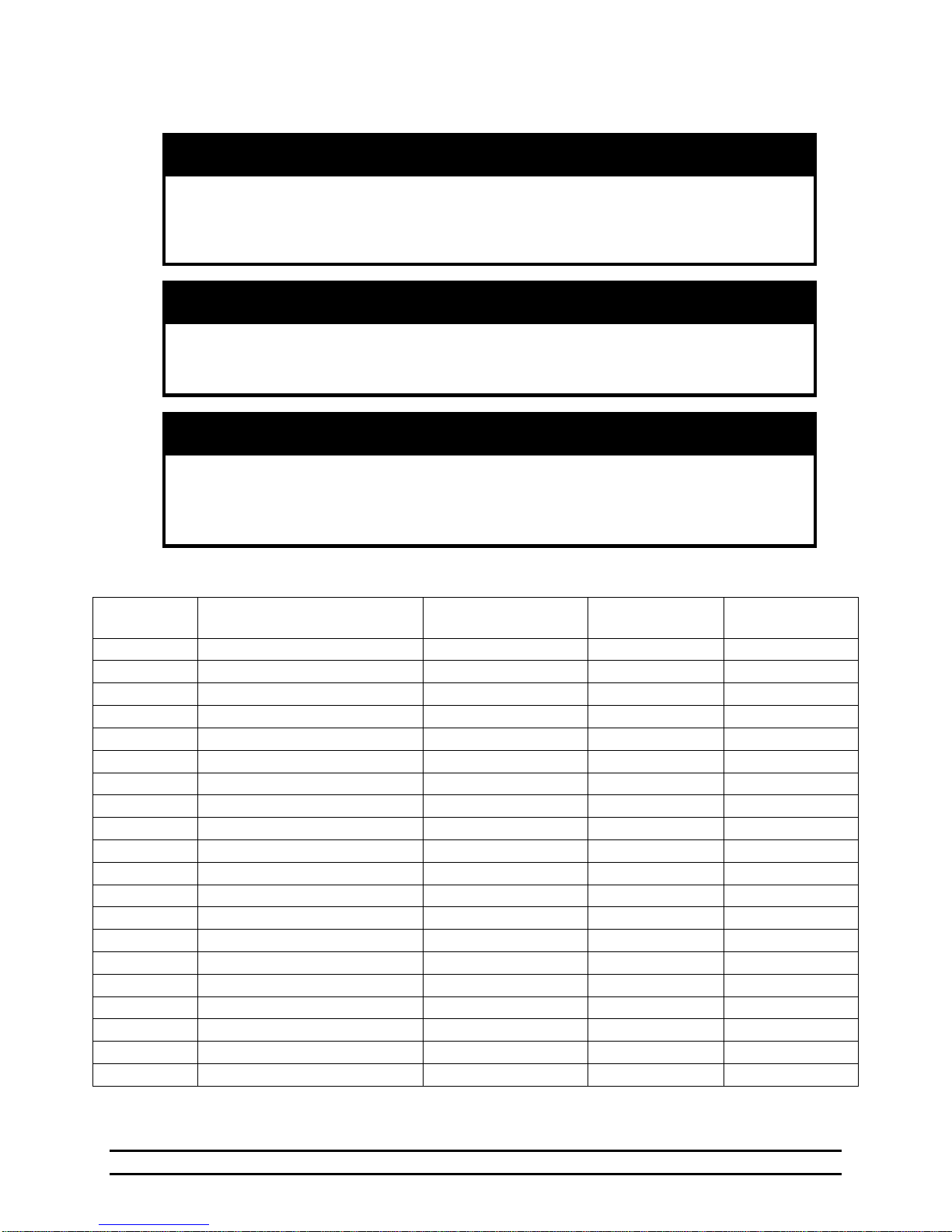
HHI Part
Number
Model
Power Supply
Curtain Output
Stage Output
6607-8015
EV-Back-up
120/230 VAC 50/60 Hz
½ HP @ 240 VAC
12V, 3A
6607-8016
EV-16-Expansion
120/230 VAC 50/60 Hz
NA
1 HP @ 240VAC
6607-8020
EV-3000-R1-00
120/230 VAC 50/60 Hz
½ HP @ 240 VAC
N/A
6607-8021
EV-3000-16-00
120/230 VAC 50/60 Hz
N/A
1 HP @ 240 VAC
6607-8022
EV-3000-16-01
120/230 VAC 50/60 Hz
½ HP @ 240 VAC
1 HP @ 240 VAC
6607-8023
EV-3000-16-02
120/230 VAC 50/60 Hz
½ HP @ 240 VAC
1 HP @ 240 VAC
6607-8024
EV-3000-16-03
120/230 VAC 50/60 Hz
½ HP @ 240 VAC
1 HP @ 240 VAC
6607-8025
EV-3001-16-00
120/230 VAC 50/60 Hz
N/A
1 HP @ 240 VAC
6607-8026
EV-3001-16-01
120/230 VAC 50/60 Hz
½ HP @ 240 VAC
1 HP @ 240 VAC
6607-8027
EV-3001-16-02
120/230 VAC 50/60 Hz
½ HP @ 240 VAC
1 HP @ 240 VAC
6607-8028
EV-3001-16-03
120/230 VAC 50/60 Hz
½ HP @ 240 VAC
1 HP @ 240 VAC
6607-8201
EV-3000-16-S0 Spanish
120/230 VAC 50/60 Hz
N/A
1 HP @ 240 VAC
6607-8202
EV-3000-16-S1 Spanish
120/230 VAC 50/60 Hz
½ HP @ 240 VAC
1 HP @ 240 VAC
6607-8203
EV-3000-16-S2 Spanish
120/230 VAC 50/60 Hz
½ HP @ 240 VAC
1 HP @ 240 VAC
6607-8204
EV-3000-16-S3 Spanish
120/230 VAC 50/60 Hz
½ HP @ 240 VAC
1 HP @ 240 VAC
6607-8205
EV-3001-16-S0 Spanish
120/230 VAC 50/60 Hz
N/A
1 HP @ 240 VAC
6607-8206
EV-3001-16-S1 Spanish
120/230 VAC 50/60 Hz
½ HP @ 240 VAC
1 HP @ 240 VAC
6607-8207
EV-3001-16-S2 Spanish
120/230 VAC 50/60 Hz
½ HP @ 240 VAC
1 HP @ 240 VAC
6607-8208
EV-3001-16-S3 Spanish
120/230 VAC 50/60 Hz
½ HP @ 240 VAC
1 HP @ 240 VAC
2. Warnings
Before connecting power to the controller, be sure to check the position of the
voltage selector switch located next to the transformer on the EVI/O board.
Use adequate ventilation to reduce the risk of overheating of controller!
When this controller is used in a life support heating and ventilation system
where failure could result in loss or injury, the user should provide adequate
Warning!
Improper positioning of this switch will cause system failure.
Warning!
Maximum operating temperature of controller is 50 C (122 F).
Warning!
back-up, or accept the risk of such loss or injury!
3. Ratings and Specifications
NOTE: Room Temperature Must Be Kept Between 32F/0C and 122F/50C.
Part No. 4801-5307 Rev 2-15 Evolution 3000 and 3001 5 of 70
Page 6
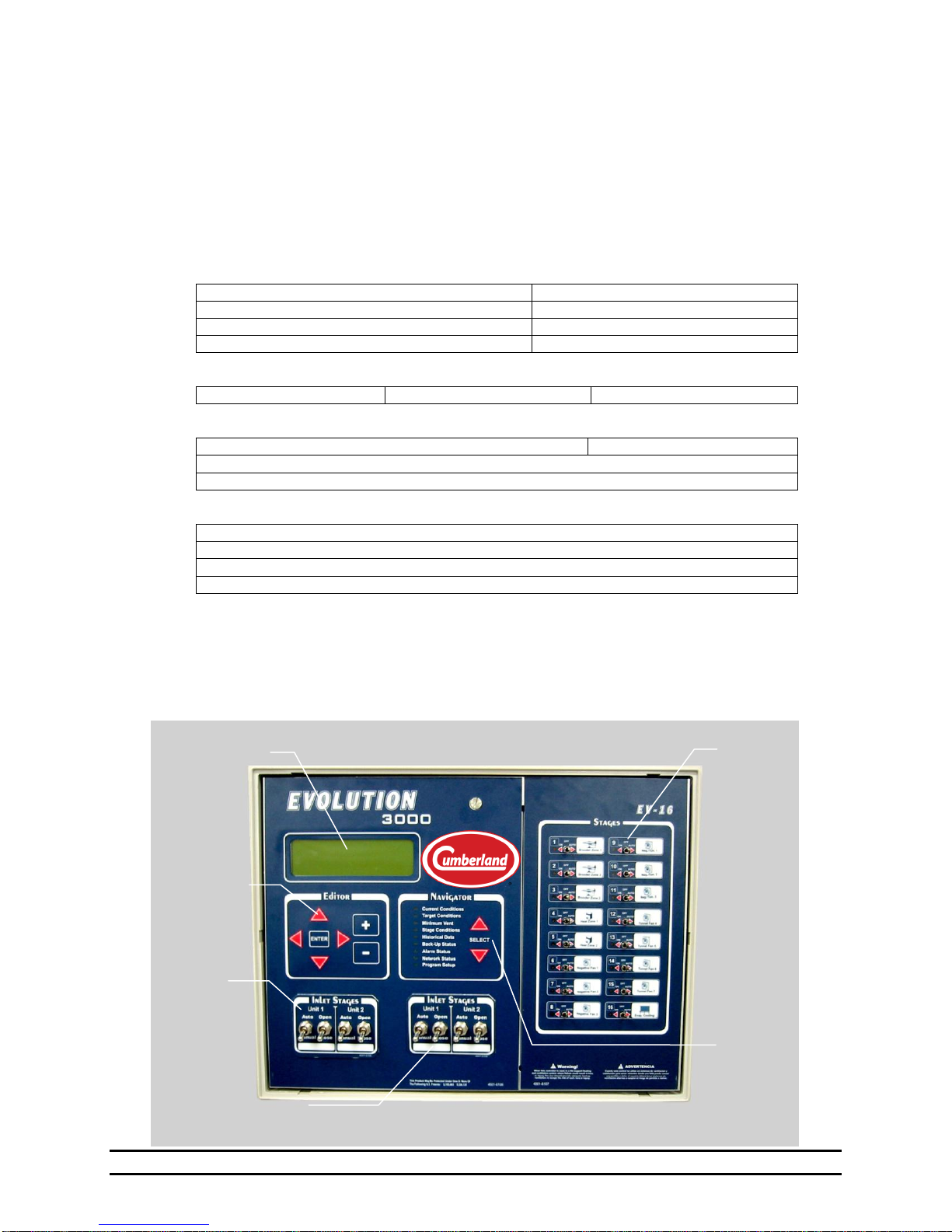
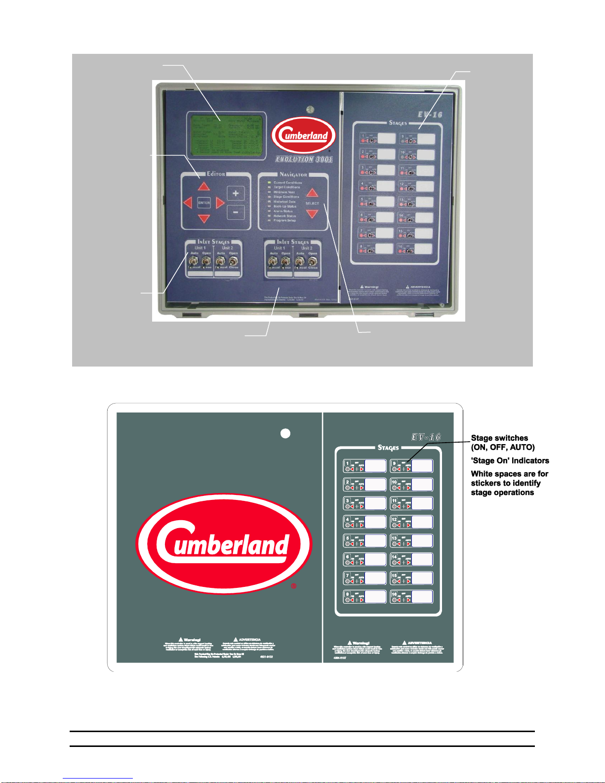
EVOLUTION 3000 FRONT PANEL
Navigator
Buttons
Optional Natural Stages
Stage switches
(ON, OFF,
AUTO)
'Stage On'
Indicators
White spaces
are for stickers
to identify stage
operations
Editor Buttons
Main Display
Optional
Ventilation
Stages
8 inside temperature sensors
1 outside temperature sensor
2 humidity sensors
1 static pressure transducer
2 digital water meter input
HHNet connection for PC compatibility
6 PowerTrak auxiliary switch inputs
2 Feed Bin Level Sensors
2 Auger Runtime Sensors
4 Belt Runtime Sensors
16 On/Off output stages with manual override switches
(2) 0-10 Vdc Analog Outputs
Open/Off/Close PowerTrak stages with manual override (Depending On Model)
1 Alarm relay with both N.O. and N.C. contacts
2 sets of Open/Off/Close PowerTrak stages with manual override
Variable speed output drive
16 On/Off output stages with manual override switches
Patented integrated Evolution Back-up
4. Introduction
The Evolution 3000 Controller is the first member of Cumberland's new environmental controller line. The
Evolution 3001 Controller has the same operational features as the 3000 except the 3001 has a larger
display. The Evolution 3000 and 3001 Controllers have 16 stages standard. The Evolution 3000 and 3001
Controllers can be expanded up to 64 stages. (i.e. 16, 32, 48 and 64 stages).
Features:
Input Device Options
Feed Management (Optional)
Output Devices (Standard)
Output Devices: (Optional)
5. Evolution Front Panel
The Evolution Controller is divided into two main areas. On the left is the Main Control Panel containing
the Main Display, Editor, Navigator and the Inlet Stage Controls. On the right are the Stage Switches. The
Navigator is used to select the information to be displayed in the Main Display. Once the desired
information is selected in the Navigator, the Editor is used to scan and modify the data.
Part No. 4801-5307 Rev 2-15 Evolution 3000 and 3001 6 of 70
Page 7
EVOLUTION 3000 EXPANSION STAGES FRONT PANEL
EVOLUTION 3001 FRONT PANEL
Navigator
Buttons
Optional
Natural
Stages
Stage switches
(ON, OFF,
AUTO)
'Stage On'
Indicators
White spaces
are for stickers
to identify stage
operations
Editor Buttons
Main Display
(Larger Scrolling Area)
Optional
Ventilation
Stages
Part No. 4801-5307 Rev 2-15 Evolution 3000 and 3001 7 of 70
Page 8
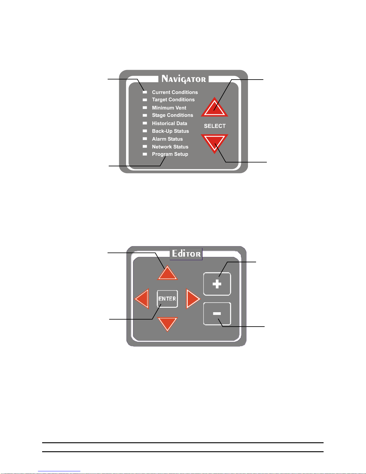
Minus button
(Use to decrease
value of variable)
Enter Button
(Links to other
screens)
Plus button
(Use to increase
value of variable)
Scroll Buttons
Function Modes
Up Select Button
Down Select
Button
Light Emitting
Diode Indicator
5.1 Navigator Panel
The Navigator buttons are used to select a controller function. Press up or down button to toggle between
functions. LED (light emitting diode) lights when a function is selected and the associated data is displayed
in the Main Display.
5.2 Editor Panel
The Editor buttons are used to select functions that appear in the Main Display screen. The arrow buttons
are used to scroll to variables that appear within the current screen of the Main Display. The plus (+) and
minus (-) buttons are used to change or modify a variable's value. The Enter button is used to link to a new
display screen of a selected variable. NOTE: To return to the main function screen, press either Up () or
Down () Navigator button.
Part No. 4801-5307 Rev 2-15 Evolution 3000 and 3001 8 of 70
Page 9
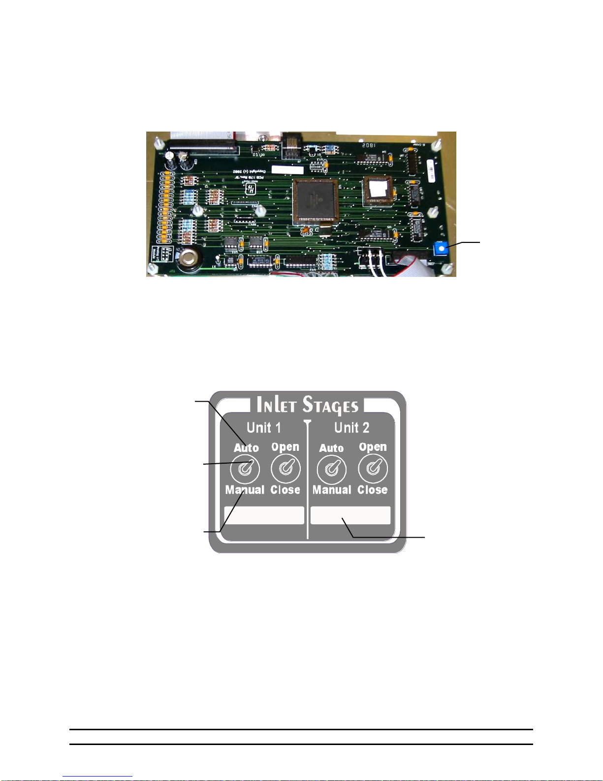
Notation Area
Manually opens or
closes inlet
Toggle switch
(Auto or Manual
operation)
Controller opens or
closes inlet
Contrast Control
5.3 Main Display Contrast
The main display contrast can be adjusted to adapt to various lighting conditions. The Contrast Control is
located on the opposite side of the front panel. Use the Contrast Control potentiometer and a small flathead screw-driver to manually darken or lighten the screen. Turn clockwise to darken the display;
Counter-clockwise to lighten the display.
CAUTION: DO NOT CONTACT OTHER COMPONENTS OR WIRES.
5.4 Inlet Stages
Optional inlet stages may be added to control vents & curtains. Up to 4 inlet stages may be added per
controller unit. When Auto/Manual toggle switch is placed in Auto position, inlet opens and closes
according to programmed instructions. Use the Open/Close toggle switch to manually open or close inlet
when Auto/Manual toggle switch is placed in Manual position. The Notation area is for labeling the inlet.
Under normal circumstances the machines should be left in automatic (Auto) as shown above.
Part No. 4801-5307 Rev 2-15 Evolution 3000 and 3001 9 of 70
Page 10
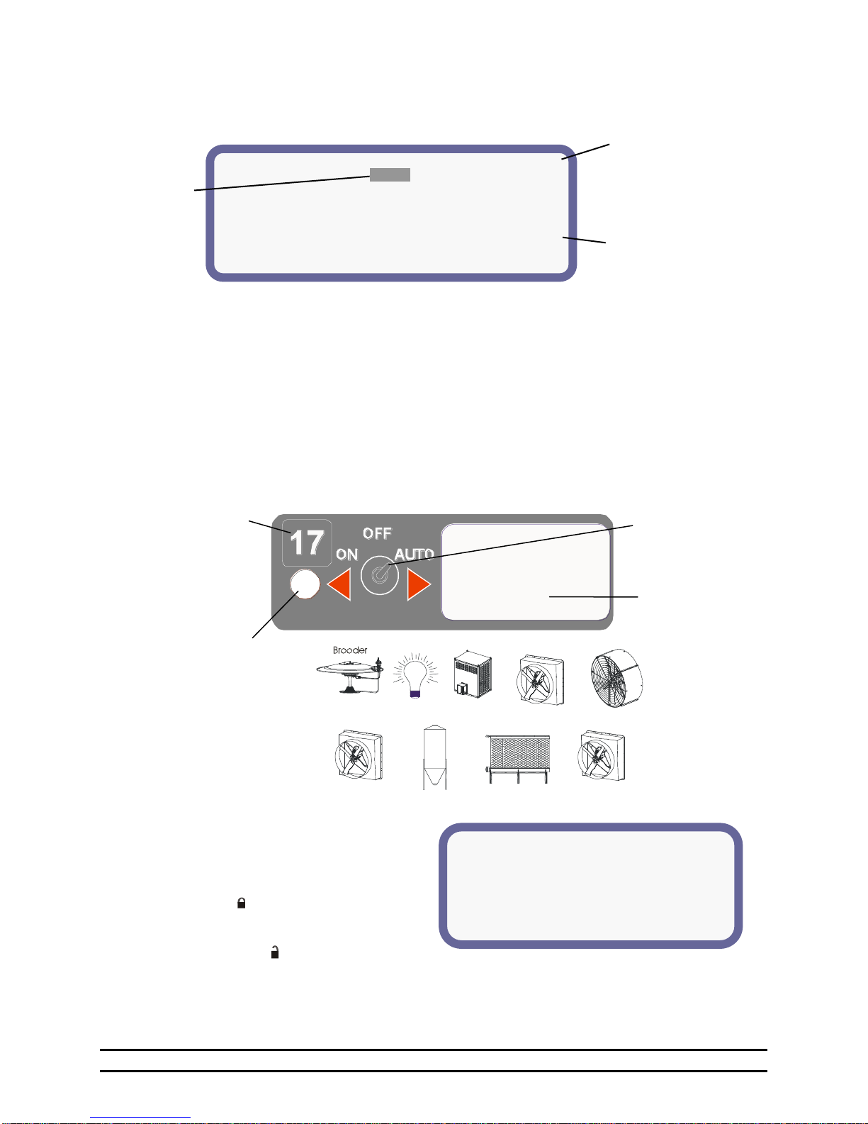
** PASSWORD PROTECTED **
You must enter the current controller
Password to continue.
Press the ENTER button to proceed.
Password: XXXX
1
1
Stage number
(Use labels to denote
stages 17-64)
ON, OFF, AUTO
Switch positions
Stick Icon label onto
white area or use for
notation
LED Indicator (lights
when stage is ON)
Icon labels are provided to
affix to white area of stage
control. Icon symbols are
shown at right.
Heater
Negative Fan
Light
Stir Fan
Neg./Tun.
Feed
Evap. Cooling
Tunnel Fan
The Scroll Symbol is a
flashing down arrow ( ) that
indicates more text outside
of display screen. Use
up/down editor arrow keys
to scroll text.
The Link Symbol ( ) is a right
pointing arrow and indicates a
link to another display screen.
To change
parameter:
Select parameter
using editor
arrow keys. Use
+ and - keys to
change value.
(1)Target Temp =
77.5°
(2)Ramping:
On
(3)Target Press =
0.04 wc
(4)Ramping:
Off
(5)Tunnel Press =
0.00 wc
(6)Target Humidity
< 60%
(7)Light Schedule
(8)Feed
Schedule
77.5°
NOTE: If Optimum Mode is turned On, the Target Conditions screen
will have differences from the standard screen shown above.
5.5 Status Display
The following is an example of Main Display screen displaying the standard Target Conditions status
screen. The Main Display screen displays both status and programming screens.
5.6 Stage Switch
The stage LED indicator lights when a stage is active. The stage switch is used to select Auto operation,
On, or Off. If switch is in Auto position, the stage operation is controlled by the controller. That is, the
stage may turn on and off according to settings selected from the Main Display screen. If switch is in the
On position, a stage is On continuously. If switch is in the Off position, a stage is Off with the exception of
Back-Up conditions.
The white space is used to affix a label indicating stage function (i.e. brooder, fan, light, cool, etc.)
NOTE: Stages 1-16 are marked on Main panel. For optional stages 17-64, use stick-on label to number
stages.
5.7 Locks
A lock feature has been included for additional
security to the Evolution 3000 and 3001 settings
with software versions V0.16 and higher. This
feature locks the Program Setup screens to
prevent changes. Locked screens are noted by a
lock symbol ( ) in the upper right of the
screen. The Target Conditions and Minimum
Vent screens are not lockable. When the lock
feature is disabled ( ), all screens will show
unlocked until the password is changed. See
Section 7.13.
NOTE: The Diagnostics screen can only be unlocked using the HHI Service Code; Contact your local
Part No. 4801-5307 Rev 2-15 Evolution 3000 and 3001 10 of 70
dealer for assistance.
Page 11
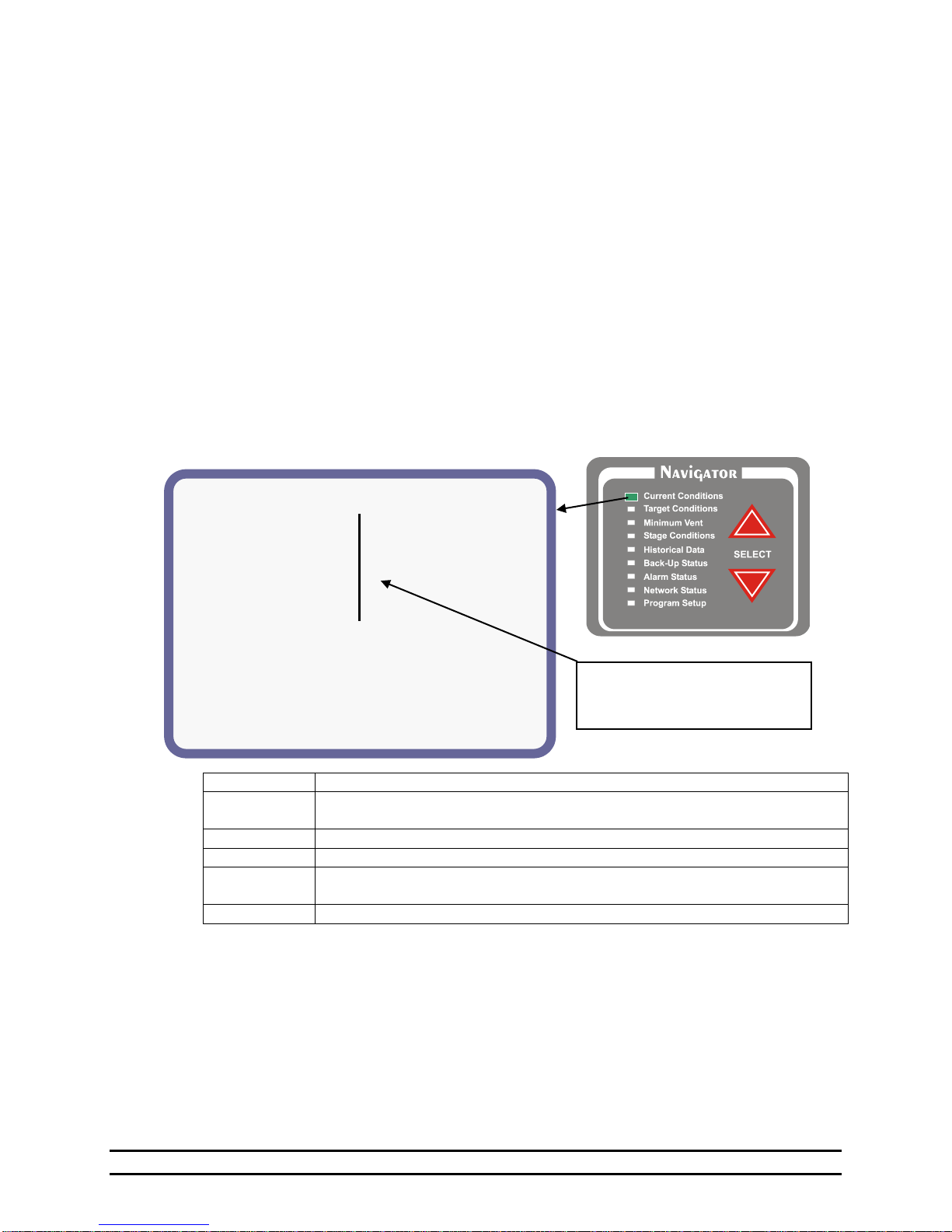
NOTE: In this manual, Reference
numbers refer to descriptions given in
text. These numbers do not appear
on display.
Mon 14 Jun 2007 5:00 p
(1) Vent Mode:
Minimum
(6) Growout Day:
40
(2) Room Temp:
71.4°
(7) Water Consumption
Target:
70.0°
1. 240
(10/hr)
(3) Outside:
77.0°
2. 280
(10/hr)
(4) Pressure:
0.00 wc
(8) Feed Levels
Target:
0.04 wc
1. 11.2ft
( 60%)
(5) Humidity:
0%
2. 5.0ft
( 23%)
(9)
* Sensor 1: 71.6°
* Sensor 2: 71.2°
* Sensor 3: 71.4°
Sensor 4:---.-°
Sensor 5:---.-°
Sensor 6:---.-°
Sensor 7:---.-°
Sensor 8:---.-°
Sensor is enabled
* Sensor used in Room Temp Calculation
VENT MODE
Definition
Minimum
Heat stages or timer fans operating. None of the negative stages are on because of
temperature.
Natural
The main curtains are open.
Power
The curtains are up and there are negative fans on because of temperature.
Transition
The control is transitioning into tunnel ventilation from either power or natural
ventilation. The control is making the adjustments needed to go into tunnel.
Tunnel
The tunnel signal has been activated and the system has entered into tunnel.
6. Viewing Navigator Status Screens
The following nine screens are available: Current Conditions, Target Conditions, Minimum Vent, Stage
Conditions, Historical Data, Back-Up Status, Alarm Status, Network Status, Program Setup. The Navigator
selects the desired status screen by pressing the up and down SELECT arrows. The first eight screens
display status information and various setup options. The last screen is the Program Screen. To change
program parameters the Program Setup Screen must be selected.
6.1 Current Conditions
The current environmental conditions of the building are shown here. Below is a table describing the
variables that can appear in the Current Conditions status screen.
The numbers in brackets e.g. (1) refer to the descriptions below the sample screen displays.
(1) Vent Mode – Indicates the current ventilation mode: either Minimum, Natural, Power, Transition or
Tunnel.
(2) Room Temp – The average temperature of the sensors for display. Target – Target Temperature.
(3) Outside (Temperature) – The outside temperature as indicated by the outside sensor.
(4) Pressure – The current atmospheric pressure internal to the building. Target – Target Pressure.
(5) Humidity – The percent of water vapor of the air inside the building.
(6) Growout Day – The current day in the growout period. The Current Conditions LED on the Navigator
panel will blink if the growout day is later then the current date.
(7) Water Consumption – Water consumed for the current day; The total for the day is listed first then the
units per hour is shown inside ( ). Two water meters may be monitored (Water Meter 1 & Meter
2).
(8) Feed Level – The Feed level is shown in number of feet from the bottom first then the percentage of
feed remaining in the feed bin is shown inside ( ). Two feed bins may be monitored (Bin #1 & Bin
#2).
(9) Sensor 1 through 8 – The current temperature read by each sensor.
Part No. 4801-5307 Rev 2-15 Evolution 3000 and 3001 11 of 70
Page 12
(1)Target Temp =
77.5°
(2)Ramping:
On
(3)Target Press =
0.04 wc
(4)Ramping:
Off
(5)Tunnel Press =
0.00 wc
(6)Target Humidity
< 60%
(7)Light Schedule
(8)Feed Schedule
Cooler Conditions
(9)Temp:
76.1°
(10)Target=
70.5°
(11)Humidity:
43%
(12)Range=
30%-35%
6.2 Target Conditions
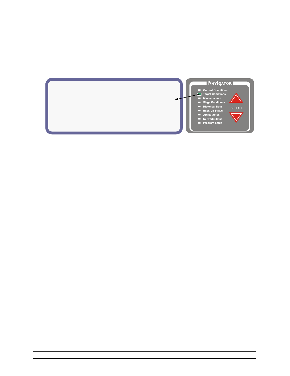
The current target environmental conditions of the building are shown below. The specific Target
Conditions screen features and setting options will depend on whether Optimum Mode is ON or OFF.
Examples and details for both the Standard screen and Optimum screen are shown in the following two
subsections.
6.2.1 Target Conditions - Standard Screen With Optimum Mode OFF
(1) Target Temp - This is the desired temperature of
(2) Ramping – Indicates if ramping of the Target
(3) Target Press - This is the desired negative
(4) Ramping – Indicates if ramping for the Target
(5) Tunnel Pressure – Indicates the desired negative
(6) Target Humidity – The desired humidity inside
NOTE: This only affects the variable timer %.
the building.
Temperature is turned On or Off. You are also
allowed to turn the temperature ramping on or off
in the program set up screen. You use the
Navigator to reach the Program Setup screen and
then navigate down to "Temperature Ramp" and
press enter. See Section 7.6.
pressure in the building. See Section 7.4.
Pressure is turned on: On or Off. You are also
allowed to turn the pressure ramping on or off in
the program setup screen. See Section 7.4.
pressure in the building while in the Tunnel
Mode. See Section 7.4.
the building (Humidity Sensor # 1) is less than
this set number. For every percentage increase in
humidity over the set %, the timer percentage
will increase.
EXAMPLE:
Target Humidity < 65%
Timer Percentage is set to 20% of 5 minutes.
If Humidity in building is at 70%, the timer
percentage will be at 25%.
Min1% and Min2% are unaffected.
(7) Light Schedule – View Light Clock Setup. See
Section 7.12.
(8) Feed Schedule – View Feed Clock Setup. See
Section 7.11.
(9) Cooler Conditions Temp – This is the current
temperature inside the cooler.
(10) Cooler Conditions Temp Target – This is the
desired temperature of the cooler.
(11) Cooler Conditions Humidity – This is the
current humidity inside the cooler (Humidity
Sensor # 2).
(12) Cooler Conditions Humidity Range – This is
the desired humidity range of the cooler.
Part No. 4801-5307 Rev 2-15 Evolution 3000 and 3001 12 of 70
Page 13

Optimum Settings
Adjustments
(1)Target Temp =
77.5°
(2)Adjust =
+0.0°
(3)Optimum Run%:
10%
(4)Adjust =
+00%
(5)Target Press =
0.04 wc
(6)Tunnel =
0.00 wc
(7)Opt. Timer:
--6-4---
(8)Humidity <
60%
(9)Light Schedule
(10)Feed Schedule
Cooler Conditions
(11)Temp:
76.1°
(12)Target=
70.5°
(13)Humidity:
43%
(14)Range=
30%-35%
6.2.2 Target Conditions – Optimum Screen With Optimum Mode ON
The target conditions screen shown below represents the display and options when the Optimum Mode is
turned On. Refer to Section 7.1 for turning the Optimum Mode On or Off and Section 7.6.2 for the
Optimum Mode Growout Curve.
(1) Target Temp – Displays the desired temperature of the building for the current growout day.
(2) Adjust – Adjusts the programmed Target Temperature by this amount until set otherwise. The displayed Target
Temp to the left will increase or decrease as this number is adjusted.
(3) Optimum Run% – Displays the minimum vent run % for the current growout day. The Run % is the percentage
of the Minimum Timer Cycle that the stage will run.
(4) Adjust – Adjusts the programmed Optimum Run% by this amount until set otherwise. The displayed Optimum
Run% to the left will increase or decrease as this number is adjusted.
(5) Target Press - This is the desired negative pressure in the building. See Section 7.4.
(6) Tunnel Pressure – Indicates the desired negative pressure in the building while in the Tunnel Mode. See
Section 7.4.
(7) Opt. Timer – Displays the current optimum timer active determined by the growout curve.
(8) Humidity – The desired target humidity inside the building (Humidity Sensor # 1) is less than this set number.
For every percentage increase in humidity over the set %, the timer percentage will increase.
EXAMPLE:
Target Humidity < 65%
Timer Percentage is set to 20% of 5 minutes.
If Humidity in building is at 70%, the timer percentage will be at 25%.
NOTE: This only affects the variable timer %. Min1% and Min2% are unaffected.
(9) Light Schedule – View Light Clock Setup. See Section 7.12.
(10) Feed Schedule – View Feed Clock Setup. See Section 7.11.
(11) Cooler Conditions Temp – This is the current temperature inside the cooler.
(12) Cooler Conditions Temp Target – This is the desired temperature of the cooler.
(13) Cooler Conditions Humidity – This is the current humidity inside the cooler (Humidity Sensor # 2).
(14) Cooler Conditions Humidity Range – This is the desired humidity range of the cooler.
Part No. 4801-5307 Rev 2-15 Evolution 3000 and 3001 13 of 70
Page 14
(1) MINIMUM TIMERS:
(2)Cycle = 5 m ( 300s)
(6)VARIABLE SPEED:
(3)Min1 % = 40% ( 215s)
(7)V1 Minimum % = 50%(55%)
(4)Min2 % = 20% ( 108s)
(8)V2 Minimum % = 40%(100%)
(5)Var % = 20% ( 108s)
(9)VARIABLE TIMER:
(10)Sensors = Outside
(11)Max Run % = 65%
(12)Max Temp = 85.0°
(13)Min Run % = 20%
(14)Min Temp = 70.0°
(15)COOL TIMER:
(16)Max Run % = 100%
(17)Cycle = 10 m ( 600s)
(18)Min Run % = 55%
NOTE: Cycle in seconds
NOTE: Run Time in seconds
6.3 Minimum Vent
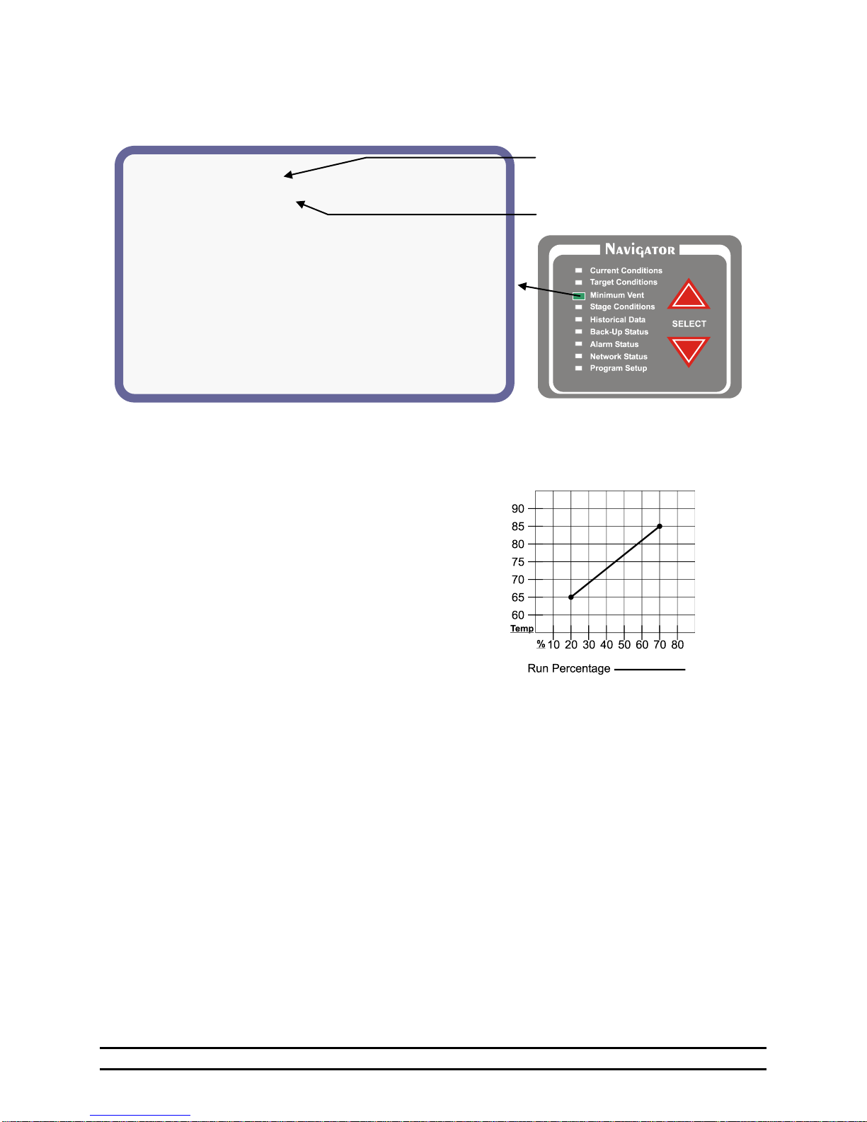
The Minimum Vent status screen display:
(1) Minimum Timer 1 - The Minimum timer one and
two both share the same cycle time. Different timer
percentages may be set for minimum 1 vs.
minimum 2. If the vent anticipation is being used,
the vents will start opening before a negative
ventilation stage turns on and will adjust until the
vent opening necessary for the desired target
pressure is achieved.
(2) Cycle - The length of Timer 1 cycle. Cycle = 1 to
20 minutes.
(3) Min1 % - The percentage of the Timer 1 cycle that
the stage will run.
(4) Min2 % - The percentage of the Timer 2 cycle that
the stage will run.
(5) Var % - The percentage of time a stage is
currently running using the variable timer based off
the temperature.
NOTE: The Minimum timer one and two both share
the same cycle time. Different timer percentages
may be set for Minimum 1 and Minimum 2. If the
vent anticipation is being used, both Minimum 1
and Variable will start the vents open before a stage
comes on.
(6) Variable Speed: These settings are used to set up
variable speed fan operation.
(7) V1 Minimum - The minimum speed or minimum
percentage of light intensity for V1; The value
inside the parenthesis shows the current
percentage.
(8) V2 Minimum -The minimum speed or minimum
percentage of light intensity for V2; The value
inside the parenthesis shows the current percentage.
(9) Variable Timer - The variable timer is similar to
the expanded timer found in the System 2000 PC-8.
The variable timer will vary the timer based on
temperature. See chart shown below.
(10) Sensors - The sensors used to determine the run
time. Active sensors will be indicated by a number
starting with #1 from right to left. Inactive sensors
will be indicated by a - or hyphen. When "outside-"
is displayed, outside sensor is active. For example,
If sensors 1, 2 and 3 are being used, "-----321" will
be displayed. When “outside” is displayed, the
outside sensor is active.
NOTE: When any of the temperature sensors #1-8 are
selected, the “Max Temp” and “Min Temp”
settings will float with the Target Temperature.
When “outside” is selected, the variable timer
strictly uses the “Max Temp” and “Min Temp”
values selected and are not associated with the
Target Temperature (will not float with Target).
(11) Max Run % - The maximum Run Time
percentage.
(12) Max Temp - The temperature at which the timer
will run Maximum Run time % percentage.
(13) Min Run % - The minimum Run Time
percentage.
Part No. 4801-5307 Rev 2-15 Evolution 3000 and 3001 14 of 70
Page 15
Inlet Conditions
#
STATUS
MODE
PRESS
OPENED
CLOSED
U1
Close
Vent
0.00
No
No
U2
Close
Tun
0.00
No
No
#
STATUS
MODE
RTEMP
ON
OFF
TIME
-----------
TARGET
70°
---------
V1
0%
CTUN
79.4°
89.4
89.0
Ramp
V2
0%
Cstir
79.6°
89.4
89.0
None
1
On
Light
Ramp
2
On
Cstir
79.6°
76°
95°
None
. . . . . . .
16
On
Cstir
79.6°
76°
95°
Min1
Inlet Conditions
(1)#
(2)STATUS
(3)MODE
(4)PRESS
(5)OPENED
(6)CLOSED
U1
Open
Vent
0.04
No
No
U2
Close
Tun
0.04
No
Yes
. . . . . . .
. . . . . . .
(14) Min Temp - The minimum temperature. The
timer will be at minimum Run %.
(15) Cool Timer: Cool timer is also allowed a
different timer cycle if needed. This can be used
for foggers or cool cell systems.
(16) Max Run - The Cool Timer Maximum Run Time
percentage.
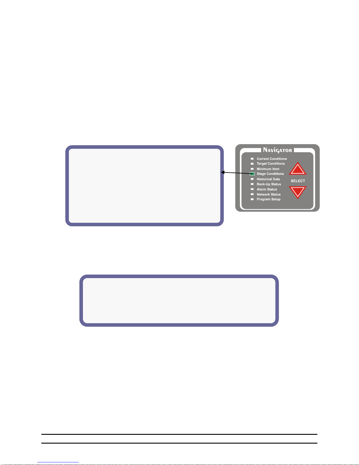
6.4 Stage Conditions
When the Stage Conditions screen is selected by using the Navigator Select arrows, the following menu
screen is shown. Use the up and down arrows in the Editor to view the desired information. Notice that the
Light Clock and Feed Clock Stages are listed after the Inlet Conditions section. The Heat Stages are then
displayed in order of increasing ON Temperatures. The Cool stages, including the Variable Output stages,
are listed below the Target Line in order of increasing ON Temperatures.
(17) Cycle - Cycle Time in Minutes. Cool timer is
also allowed a different timer cycle if needed.
This will be used for foggers or cool cell systems.
(18) Min Run - The Cool Timer Minimum Run Time
percentage.
6.4.1 Inlet Conditions
The Inlet Conditions part of the Stage Conditions screen is used to control Power Trak operation for power
ventilation. U1 is normally for baffle boards and U2 controls tunnel inlets.
(1) #- The stage bank either U1 or U2.
(2) Status - Indicates if the Stage is Off, Opening or Closing.
(3) Mode – The mode column tells you how the machine will be operating. If it will be a vent machine
"VENT" or a tunnel machine "TUN" machine.
(4) Pressure – Indicates the pressure in the building.
(5) Opened – Indicates if the machine is fully open (Yes or No). When the machine is fully open on the
open auxiliary switch, this column will indicate a “Yes”.
(6) Closed – Indicates if the machine is fully closed (Yes or No). When the machine is fully closed on the
closed auxiliary switch, this column will indicate a “Yes”.
Part No. 4801-5307 Rev 2-15 Evolution 3000 and 3001 15 of 70
Page 16
. . . . . . . . . . . . . .
(1)#
(2)STATUS
(3)MODE
(4)RTEMP
(5)ON
(6)OFF
(7)TIME
TUN
OFF
CTUN
79.4°
85°
80°
1 On
Light
Ramp
2
On
Cstir
79.6°
76°
95°
None
. . . . . . .
-----------
(8)TARGET
70°
---------
. . . . . . .
16
On
Cstir
79.6°
76°
95°
Min1
(1)#
(2)STATUS
(3)MODE
(4)RTEMP
(5)ON
(6)OFF
(7)TIME
.
. . . . . . .
. . . . . . .
. . . . . . .
. . . . . . U1
On
NAT
CLOSE
73.0°
72.0°
CLOSED: NO
U2
On
N&T
CLOSE
73.0°
72.0°
CLOSED: NO
Min1
U1
Off
NAT
OPEN
73.0°
74.0°
CLOSED: NO
U2
Off
N&T
OPEN
73.0°
74.0°
CLOSED: NO
.
. . . . . . . . . . . . .
6.4.2 On/Off Stages
The On/Off stages are used for devices that do not need a variable speed capability. This portion of the
Stage Conditions screen shows how the On/Off Stages and are set.
(1) # - Identifies the On\Off stage number
or Tunnel and lists them in the order
of priority. Tunnel is not a stage like
the Stage Master and Vent Master.
This parameter is set in the tunnel
ventilation of Program Setup screen.
See Section 7.7, Tunnel
Ventilation.
(2) Status - Indicates if the stage is currently
Timed, On, or Off.
(3) Mode - This column indicates how the
stage is programmed. Any stage can
be set to any of these modes. The
available stage options are: Off,
Heat, CSTIR, CNEG, CNEGT,
CTUN, LIGHT, FEED or CEVAP.
(4) Rtemp - The Rtemp column will indicate the
current temperature from which the stage is
operating.
(5) On – The current temperature setting for the on
point temperature of the stage.
(6) Off - The current temperature setting for the off
point temperature of the stage.
(7) Time - This column indicates if a stage is on a
timer and shows the different timers you are
allowed to put a stage on. The timer options
are: None, Min1, Min2, Var, Cool, or Opt
xx.
(8) Target – Target Temperature.
6.4.3 Natural Ventilation Stages
Natural Ventilation stages are used to open and close side curtains to allow natural ventilation.
(1) #- The stage bank either U1 or U2.
(2) Status - This column will indicate whether the machine is Off, Opening or Closing.
(3) Mode – The mode column indicates how the machine will be operating. It will be a natural curtain
"NAT" or a natural and tunnel "N&T" machine(U2 only). OPEN or CLOSE will be shown beside
the mode to show whether the specific line refers to the Open or Close function.
(4) Rtemp –The Rtemp column will indicate the current temperature the curtain machine is operating from.
(5) ON – The temperature at which the stage operates.
(6) OFF and (7) TIME – This column indicates if the machine is fully closed. When the machine is on the
closed auxiliary switch, this column will display “Yes”.
Part No. 4801-5307 Rev 2-15 Evolution 3000 and 3001 16 of 70
Page 17
(1)#
(2)STATUS
(3)MODE
(4)RTEMP
(5)ON
(6)OFF
(7)TIME
.
. . . . . . V1
50%
Light
Ramp
.
. . . . . . .
. . . . . . .
. . . . . . .
V2
75%
CStir
88.7°
76.4°
74.0°
None
Min1
.
. . . . . . .
. . . . .
.
Select and Press ‘Enter’:
Room Temperature Stage 1 – 16 RunTimes
Humidity Stage 17 – 32 RunTimes
Water Usage #1 Stage 33 - 48 RunTimes
Water Usage #2 Stage 49 – 64 RunTimes
Ventilation Mode PowerTrack RunTimes
Feed History Alarm Log
Belt Runtimes Cooler Temp
(1)DAY (2)HIGH TEMP (3)AVE (4)LOW TEMP
21 71.0°-12:34p 66.3° 61.6°–12:34a
20 71.0°-12:34p 66.3° 61.6°–12:34a
. . . . . .
. . . . . .
1 71.0°-12:34p 66.3° 61.6°–12:34a
6.4.4 Variable Stages
The Variable stages are used to control devices (i.e. fans & lights) with a variable capability.
(1) # - The Stage bank either V1 or V2.
(2) Status - This is the current run percentage that the device is operating.
(3) Mode – Indicates how the stage is programmed: CSTIR, CNEG, CNEGT, CTUN or LIGHT.
(4) Rtemp –The Rtemp column indicates the current temperature from which the stage is operating.
(5) ON –The ON column indicates the maximum ON temperature at which the variable speed fan will reach
full speed.
(6) OFF -The OFF column indicates the minimum ON temperature at which the fan will run at minimum
speed.
(7) Time – None, Min1, Min2, Var or Always ON (ON). Always ON when Rtemp is below MIN ON.
6.5 Historical Data
This screen provides access to historical data. Highlight the selection and press the ENTER button on the
EDITOR panel.
6.5.1 Room Temperature
This screen shows the highest and lowest
room temperature for each day for up to 99
days. The last day reported will appear at the
top of the list. The list can contain data up
to 99 days. After displaying 99 days, oldest
data will be deleted.
(1) Day – The specific day in the growout
period. Values = 1 day to 99 days.
(2) High Temp – The high recorded temperature and the time of day that it occurred.
(3) AVE – The average recorded temperature for the day.
(4) Low Temp - The low recorded temperature and the time of day low temperature occurred.
NOTE: The High and Low temperature readings are taken from the Sensors for Display in "Sensor Setup"
of the Program Setup Screen.
Part No. 4801-5307 Rev 2-15 Evolution 3000 and 3001 17 of 70
Page 18
Water Meter 1
(1)DAY (2)HIGH RATE (3)DAILY TOTALS
41 24/hr-12:00p 240
40 20/hr-12:34p 210
. . . .
35 10/hr-11:15p 200
. . . .
. . . .
24 15/hr-12:05p 130
. . . .
. . . .
1 5/hr-1:00p 50
(1)DAY (2)High Room (3)High Cooler
21 70%-12:34p 65-12:34p
20 70%-12:34p 65-12:34p
. . . . .
. . . . .
1 70%-12:34p 65–12:34p
Today Yesterday
(1)Minimum Ventilation 6:07 10:31
(2)Power Ventilation 1:10 6:29
(3)Natural Ventilation 2:00 1:00
(4)Transition to Tunnel 0:03 0:09
(5)Tunnel Ventilation 0:45 4:51
6.5.2 Humidity #1 (Room) & Humidity #2 (Cooler)
This screen shows the highest room humidity
& cooler humidity for each day for up to 99
days. The last day reported will appear at the
top of the list. The list can contain data up to
99 days. After displaying 99 days, oldest data
will be deleted.
(1) Day – The specific day in the growout
period. Values = 1 day to 99 days.
(2) High Room – The highest recorded room humidity (Humidity #1) and the time of day that it occurred.
(3) High Cooler - The highest recorded cooler humidity (Humidity #2) and the time of day that it occurred.
6.5.3 Water Usage (#1 or #2)
This screen gives the Water Usage of the
building per day of growout, high rate, and
water total. The screen display format is the
same for either water usage #1 or #2.
(1) Day– The specific day in the growout
period. Values = 1 day to 99 days.
(2) High Rate – The highest recorded water
rate and the time of day that it
occurred.
(3) Total For Each Day – The total water
usage for each day of growout.
6.5.4 Ventilation Mode
This screen shows the length of time in
hours and minutes that the Control is in
different ventilation modes. NOTE:
Natural mode is when the system is in
natural ventilation and the main curtains
are open.
Transition mode is when the control is
between power and tunnel ventilation. The
control is making the adjustments needed
to go into tunnel. Tunnel mode is when
the tunnel signal has been activated and
the system has entered into tunnel.
(1) Minimum Ventilation – The time spent in minimum mode. Heaters & timer fans running.
(2) Power Ventilation – The time spent in the Power Ventilation mode.
(3) Natural Ventilation – The time the side wall curtains are open.
(4) Transition to Tunnel – The time required to transit to tunnel mode. (3 minutes per transition)
(5) Tunnel Ventilation – The time spent in the Tunnel mode.
Part No. 4801-5307 Rev 2-15 Evolution 3000 and 3001 18 of 70
Page 19
(1)Day (2)Belt1 Belt2 Belt3 Belt4
(3)Status On On On On
141 2:24 2:24 2:24 2:24
140 2:24 2:24 2:24 2:24
. . . . .
. . . . .
1 2:24 2:24 2:24 2:24
(1)Day (2)Usage (3)Auger1 (4)Auger2
(5)Status On On
41 2100 lb 4:10 9:10
40 2000 lb 3:00 8:00
. . . .
35 1500 lb 3:00 8:00
. . . .
. . . .
24 1000 lb 1:30 6:30
. . . .
. . . .
1 150 lb 1:10 6:10
(1)Stage (2)Current Day (3)Previous Day
1 2:24 2:24
2 2:24 2:24
. . .
. . .
16 2:24 2:24
Stage Current Day Previous Day
(1)Inlet #1
Open 8:00 8:00
Close 10:00 10:00
(1)Inlet #2
Open 10:00 10:00
Close 10:00 10:00
(2)Nat #1
Open 1:00 1:00
Close 23:00 23:00
(2)Nat #2
Open 1:00 1:00
Close 23:00 23:00
6.5.5 Feed History
This screen shows the estimated daily
amount of feed used and the total time
that the feed line motors have been
running.
(1) Day – The specific day in the
growout period. Values = 1
to 99 days.
(2) Usage – The amount of feed used
from Bin #1 and Bin #2
combined for each day of
growout. Measurements =
pounds (lb.).
(3) Run 1 – The total amount of run-time feed line #1 was running for each day of growout. Measurements
= Hours and minutes.
(4) Run 2 – The total amount of run-time feed line #2 was running for each day of growout. Measurements
= Hours and minutes.
(5) Status – The status of the auger current sensor whether the sensor is On or Off. ON indicates the motor
is running and OFF indicates the motor is not running.
6.5.6 Belt Run Times
This screen shows the history of the Belt
runtimes. It keeps track of the last 100 days.
(1) Day – The specific day in the growout
period.
(2) Belt 1 thru Belt 4 – The length of time in
hours and minutes that the Belt has run
on the current day.
(3) Status – The status of the belt current sensor whether the sensor is On or Off. ON indicates the motor is
running and OFF indicates the motor is not running.
6.5.7 Stage Run Times
This screen shows the length of time in hours and
minutes that the individual stages have run, on
the current day and previous day.
(1) Stage – Identifies the stage number.
(2) Current Day – The length of time in hours
and minutes that the stage has run on the
current day.
(3) Previous Day - The length of time in hours and minutes that the stage has run on the previous day.
6.5.8 Power Track Run Times
This screen shows the length of time that
the Power Track equipment has been
running.
(1) Inlet #1 and #2 - The length of time
in hours and minutes that the
inlets have run on the current
and previous days.
(2) Natural #1 and #2 - The length of
Part No. 4801-5307 Rev 2-15 Evolution 3000 and 3001 19 of 70
time in hours and minutes that
the natural inlets have run on the
current and previous days.
Page 20
(1)DAY (2)HIGH TEMP (3)LOW TEMP
21 71.0°-12:34p 61.6°–12:34a
20 71.0°-12:34p 61.6°–12:34a
. . . . .
. . . . .
1 71.0°-12:34p 61.6°–12:34a
** Alarm Log **
1 (1)Tunnel Vent (2)Corrected @ (3)2/ 5 (4)1:26p
2 Low Press Failure @ 2/ 5 1:09p
3 Lo Water Rate Corrected @ 2/ 3 3:39p
4 Cycle Press Failure @ 2/ 1 4:15a
5 Low Temp Corrected @ 1/ 30 3:09p
6 Lo Water Rate Corrected @ 1/ 27 12:38a
7 Lo Water Rate Corrected @ 1/ 21 7:45a
8 Lo Water Rate Corrected @ 1/ 17 9:52p
9 Low Pressure Failure @ 1/ 15 5:21p
10 Max Runtime1 Corrected @ 1/ 10 8:27a
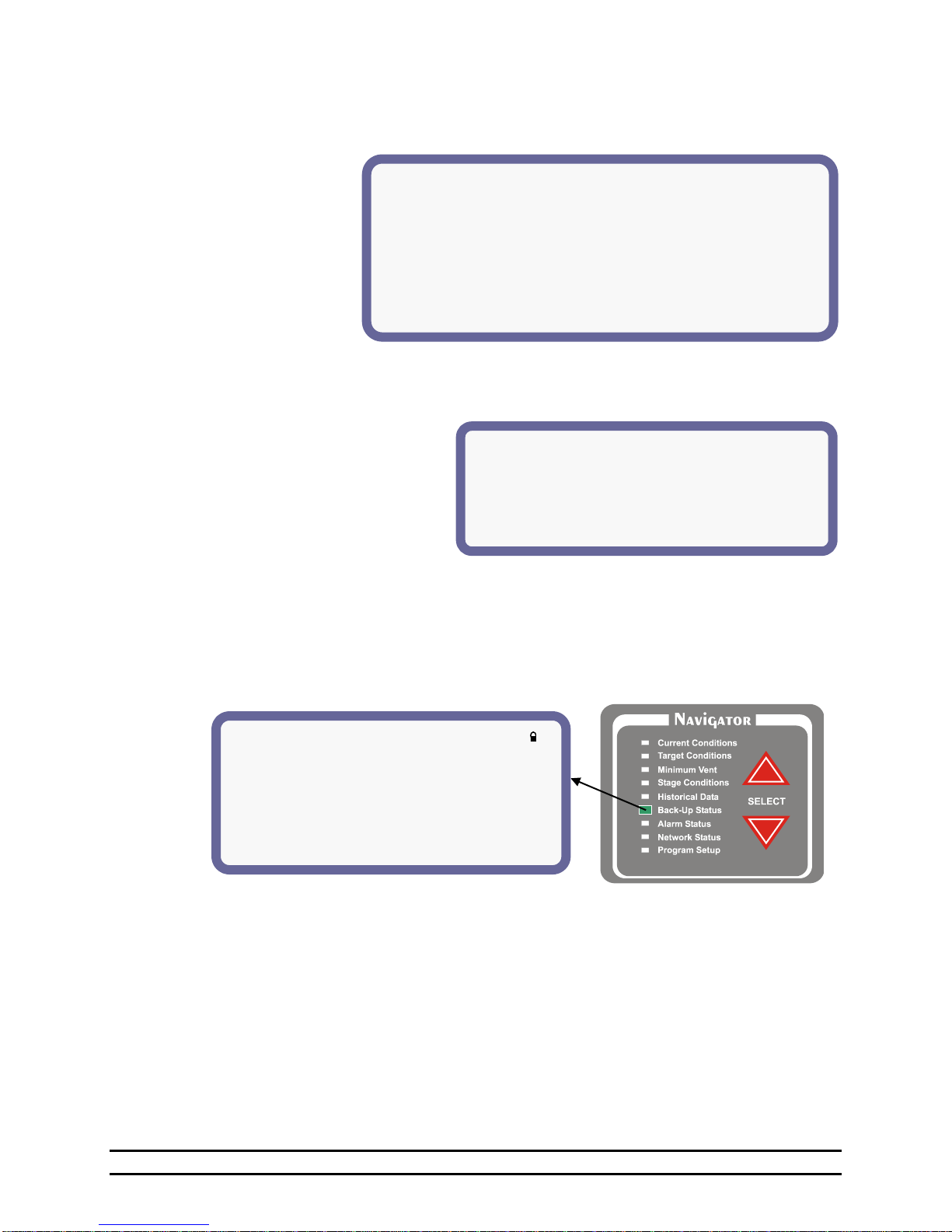
(1)Back-Up High Limit: 86°
(2)Target Temperature: 70°
(3)Back-Up Low Limit: 60°
(4)Back-Up Run %: 0% (5)Cycle: 5 minutes
(6)Warning if Back-Up +/- 11° from Target
(7)Alarm if Back-Up +/- 12° from Target
6.5.9 Alarm Log
This screen shows the list of the past 20 alarms and status information starting with the most recent
occurrence.
(1) Alarm Description –
The alarm problem
area.
(2) Alarm Status – The
alarm status
(Failure or
Correted).
(3) Date of Alarm – The
date the alarm
occurred or was
corrected.
(4) Time of Alarm – The time the alarm occurred or was corrected.
6.5.10 Cooler Temp
This screen shows the highest and lowest
cooler room temperatures for each day for
up to 99 days. The last day reported will
appear at the top of the list. The list can
contain data up to 99 days. After displaying
99 days, oldest data will be deleted.
(1) Day – The specific day in the growout
period. Values = 1 to 99 days.
(2) High Temp – The high recorded temperature and the time of day that it occurred.
(3) Low Temp – The low recorded temperature and the time of day low temperature occurred.
NOTE: The Cooler High and Low temperature readings are recorded ONLY from Sensor 8 for display in
"Sensor Setup" of the Program Setup Screen.
6.6 Back-Up Status
The Back-Up status shows the status information concerning back-up operation.
NOTE: This is the high and low limit of the Evolution Back-Up system. These setting are set in the Back-
Up system.
(1) Back-up High Limit – The high temperature limit at which the Back-up stages will start turning on cool
stages.
(2) Target Temperature – Backup target temperature.
(3) Back-Up Low Limit - The low temperature limit at which the Back-up will turn on the heat stage.
(4) Back-Up Run % The Back-up timer percentage.
NOTE: This is the timer percentage of the Evolution Back-Up system. This setting is set in the Back-Up
Part No. 4801-5307 Rev 2-15 Evolution 3000 and 3001 20 of 70
system. This setting is automatically calculated based on the controller target temperature. If the
Back-Up fails to communicate with the Evolution 3000 control the Back-Up will display an LnE.
At this point the Back-Up will take over minimum ventilation by running all Cool 1 circuits on this
timer. This percentage is how long the fan will run out of five minutes.
Page 21
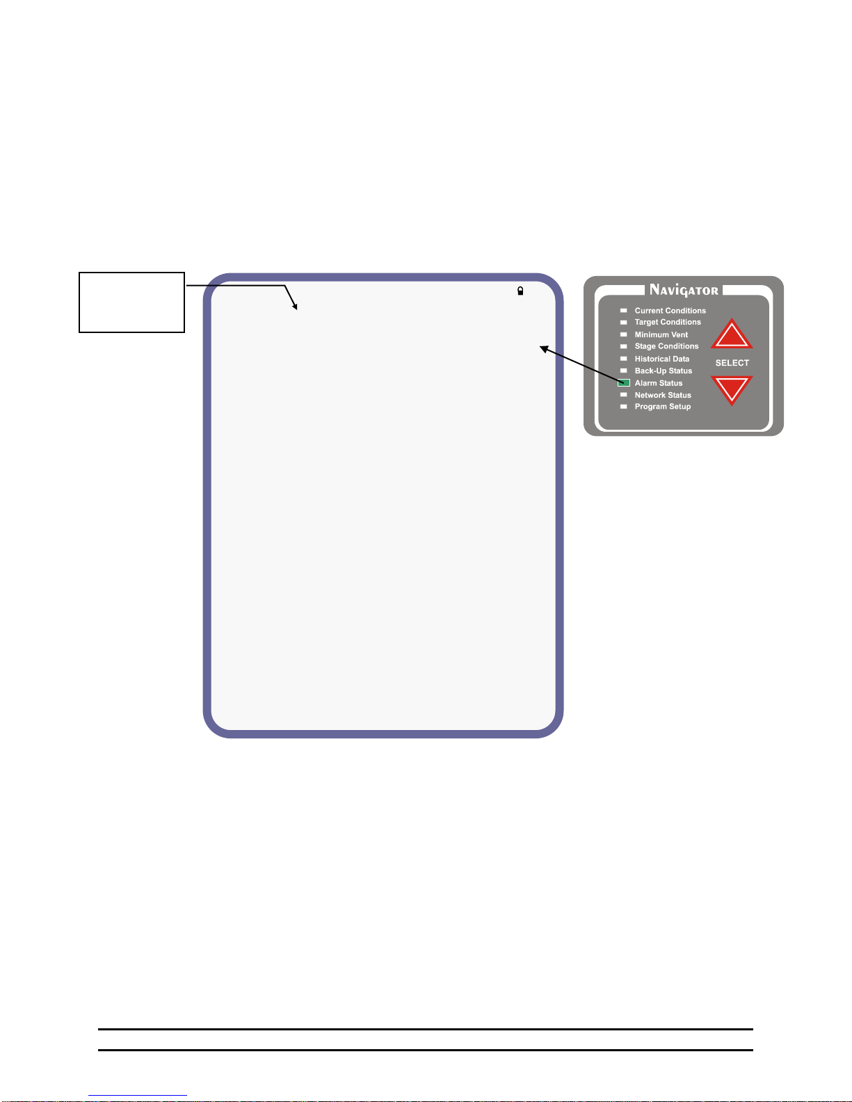
(1) High Temperature Limit & Status - The high temperature setting at which the alarm relay will activate.
See Section 6.7.1.
(2) Low Temperature Limit & Status - The low temperature setting at which the alarm relay will activate. See
Section 6.7.2.
(3) Cooler High Temperature Limit & Status - The high temperature cooler setting at which the alarm relay
will activate. This temperature is taken ONLY from temperature sensor #8.
(4) Cooler Low Humidity Limit & Status - The low humidity setting at which the alarm relay will activate.
This humidity is taken ONLY from humidity sensor #2.
(5) Cycle Pressure Limit & Status - The pressure setting at which the alarm relay will activate provided the
pressure differential is not seen during the timer period.
(6) High Pressure Limit & Status - The High Pressure alarm will send a signal to your existing alarm system
when the pressure exceeds the High Pressure Setpoint for greater than 45 seconds. (High Negative Pressure)
This alarm warns if the vents did not open for some reason (Automatically enabled during Tunnel).
NOTE: The High and Low
temperature reading is taken from
the Sensors for Display in "Sensor
Setup" of the Program Setup Screen.
Proceed
to Detail
Screens
TEMPERATURE LIMIT STATUS LAST ALARM
(1)High Temp 85.0° OK 08/15-10:36p
(2)Low Temp 65.0° OK 08/10-03:36p
COOLER ALARMS LIMIT STATUS LAST ALARM
(3)High Temp 85.0° OK 08/15-10:36p
(4)Low Humidity 20% OK 08/10-03:36p
PRESSURE LIMIT STATUS LAST ALARM
(5)Cycle Press 0.04 Off 08/09-07:36p
(6)High Press 0.15 Off 07/22-01:36p
(7)Low Press 0.03 Off 07/13-06:36p
WATER ALARMS LIMIT STATUS LAST ALARM
(8)High Rate #1 100/hr OK 01/01-12:00a
(9)Low Rate #1 25/hr OFF 01/01-12:00a
(8)High Rate #2 100/hr OK 01/01-12:00a
(9)Low Rate #2 25/hr OFF 01/01-12:00a
FEED ALARMS LIMIT STATUS LAST ALARM
(10)Auger Run1 10min OFF 01/01-12:00a
(11)Auger Run2 10min OFF 01/01-12:00a
SYSTEM STATUS STATUS LAST ERROR
(12)Tunnel Vent ---- OK 07/12-02:36p
(13)Growout Day ---- OK 07/31-05:36p
(14)Local Network---- OK 07/27-05:36p
(15)Back-Up Limits -- OK 07/31-05:36p
(16)Sensor 1 ---- OK 07/27-05:36p
(16)Sensor 2 ---- OK 06/10-09:36p
(16)Sensor 3 ---- OK 06/11-01:36p
(16)Sensor 4 ---- OK 06/13-06:36p
(16)Sensor 5 ---- OK 06/13-03:36p
(16)Sensor 6 ---- OK 06/21-03:36p
(16)Sensor 7 ---- OK 06/17-02:36p
(16)Sensor 8 ---- OK 06/13-10:36p
(17)Outside ---- OK 07/13-02:31p
(5) Cycle 5 Minutes –The cycle time of the back-up stages is 5 minutes.
(6) Warning if Back-Up – If Backup settings are set that far away from target, Back-up status light will
flash.
(7) Alarm if Back-Up -Same as above but will also set off auxiliary alarm contact.
6.7 Alarm Status
The ALARM column lists the elements and sensors that are available. For the High and Low temperatures
and High and Low pressure, the Cycle Pressure the current Alarm Limits are shown. For all entries the
STATUS and the LAST REPORTED alarm are indicated. To change the ALARM LIMIT use the Editor
arrows to highlight the desired entry and the Plus (+) and Minus (-) buttons to increase or decrease the
desired limit.
Part No. 4801-5307 Rev 2-15 Evolution 3000 and 3001 21 of 70
Page 22
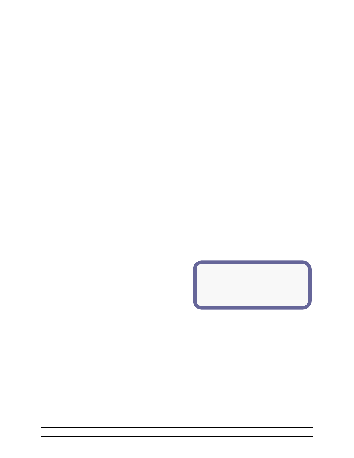
(1)High Temperature Alarm Details
(2)Alarm On/Off = Off
(3)High Temperature Limit = 81.5°
(4)Increase Limit In Tunnel = +2.0
(5)Last Alarm Statistics:
(6)Date: 02/12 (6)Time: 1:09p
(7)Cause: Sensor 1
(7) Low Pressure Limit & Status – When the Low Pressure alarm is enabled, it becomes a constant pressure
alarm. It will send a signal when pressure drops below the Low Pressure setpoint at any time for greater than
45 seconds. Setting the Low Pressure alarm setpoint to "OFF" prevents the alarm from sounding.
(8) High Rate - High water usage rate. Alarm if units per hour exceed. One or two water meters (#1 or #2) can
be monitored.
(9) Low Rate - Low water usage rate. Alarm if units per hour drop below. One or two water meters (#1 or #2)
can be monitored.
NOTE: Low Alarm is disabled when lights are off.
(10) Auger Run1 - Alarm if continuous runtime of feed line #1 exceeds selected time limit.
(11) Auger Run2 - Alarm if continuous runtime of feed line #2 exceed selected time limit.
(12) Tunnel Vent - The Tunnel alarm will send a signal if for some reason the controller is unable to enter
tunnel. See Section 6.7.3.
(13) Growout Day - Status & last error (Warning only).
(14) Local Network - Status & last error.
(15) Back-Up Limits - Status & last error.
(16) Sensor 1 through 8 Limit & Status - If the sensor is disabled, this field will show “off”. If the sensor is
enabled, this field will show “OK” if the sensor is functioning properly or “fail” if the sensor is not properly
reporting the temperature. Check wiring for damage or bad connection.
NOTE: This is the status of the alarms. Once an error has occurred the LED for Alarm Status will start blinking.
Use the Navigator arrows to move down to Alarm Status. You will see what has failed. For a detail of what
caused the failure navigate down to highlight the alarm and press enter. This will give a detail of what
caused it and when it happened. High Temp, Low Temp, and Tunnel Vent have an additional detail screen
viewable by scrolling down and highlighting the desired alarm and pressing enter.
(17) Outside -If the sensor is disabled, this field will show “off”. If the sensor is enabled, this field will show
“OK” if the sensor is functioning properly or “fail” if the sensor is not properly reporting the temperature.
Check wiring for damage or bad connection.
6.7.1 High Temperature Alarm Details
The High Temperature Alarm Details lists the settings for the alarm and the last time the alarm was sounded
and the cause of the alarm.
(1) High Temperature Alarm Details – Identifies
the following information:
(2) Alarm On/Off – The status of the alarm is On or
Off.
(3) High Temperature Limit – The current
temperature setting of the High
Temperature alarm.
(4) Increase Limit In Tunnel – Increase high temperature limit during tunnel mode by this number.
(5) Last Alarm Statistics – Identifies the date, time and cause of the last alarm.
(6) Date & Time – The date and time of the last alarm. Date is given as Month/Day.
(7) Cause – Displays the reading of the high temperature that caused the alarm.
Possible Reasons for High Temperature False Alarm Conditions:
If the same sensor causes multiple alarms, check the location of the sensor and wiring for possible
damage. Also insure that the limit is properly set for the target and room temperature.
Part No. 4801-5307 Rev 2-15 Evolution 3000 and 3001 22 of 70
Page 23
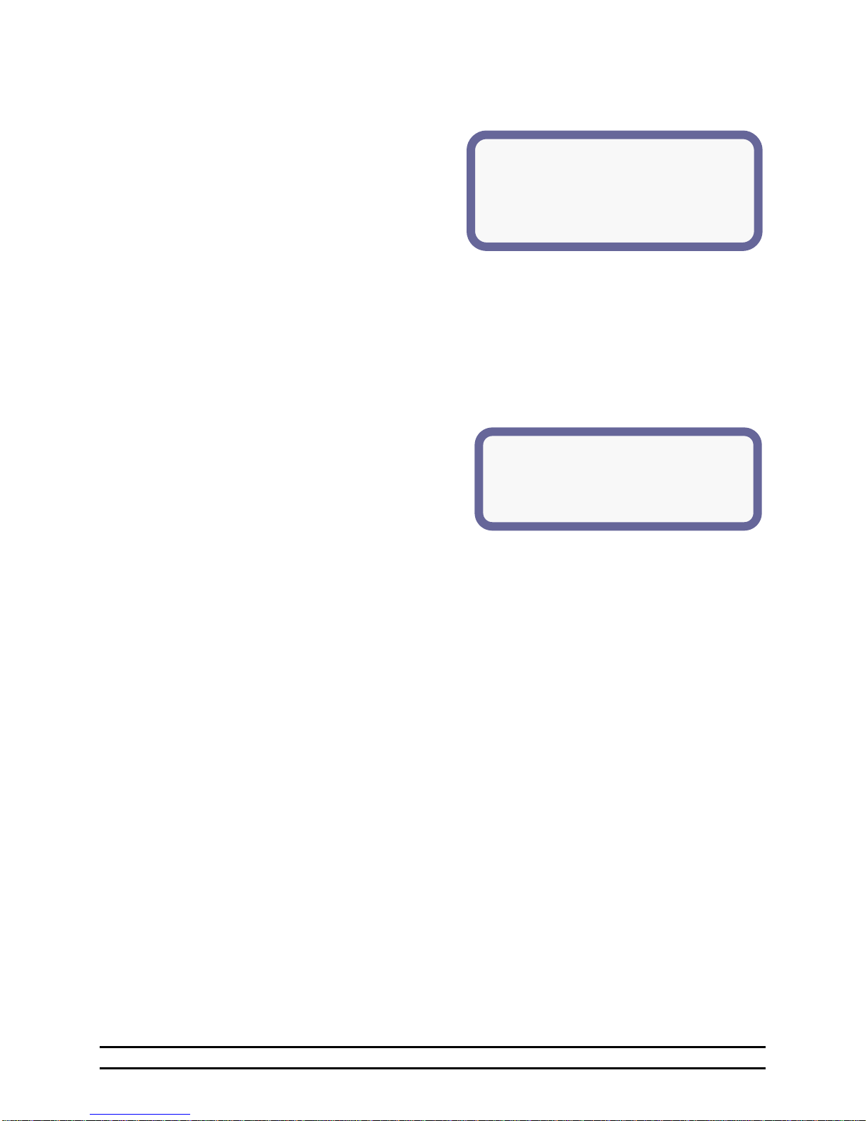
(1)Low Temperature Alarm Details
(2)Alarm On/Off = Off
(3)Low Temperature Limit = 71.5°
(4)Last Alarm Statistics:
(5)Date: 02/12 (5)Time: 1:09a
(6)Cause: Sensor 1
(1)Tunnel Alarm Details
(2)Alarm On/Off = Off
(3)Last Alarm Statistics:
(4)Date: 02/06 (4)Time: 1:09a
(5)Cause: Nat Auxiliary
6.7.2 Low Temperature Alarm Details
The Low Temperature Alarm Details lists the settings for the alarm and the last time the alarm was sounded
and the cause of the alarm.
(1) Low Temperature Alarm Details – Identifies
the following information:
(2) Alarm On/Off – The status of the alarm is On or
Off.
(3) Low Temperature Limit - The current setting of
the Low Temperature alarm limit.
(4)Last Alarm Statistics - Identifies the date, time
and cause of the last alarm.
(5) Date & Time – The date and time of the last alarm. Date is given as Month/Day.
(6) Cause - Displays the reading of the low temperature that caused the alarm.
Possible Reasons for Low Temperature False Alarm Conditions:
If the same sensor causes multiple alarms, check the location of the sensor and wiring for possible
damage. Also insure that the limit is properly set for the target and room temperature.
6.7.3 Tunnel Vent Alarm Details
The Tunnel Alarm Details shows the settings for the
alarm, the last time the alarm was sounded and the
cause of the alarm.
(1) Tunnel Alarm Details – Identifies the following
information:
(2) Alarm On/Off – The status of the alarm is On or
Off due to tunnel. Not settable. Status
indicator only. NOTE: This alarm is
automatically set by the Evolution 3000 or
3001 Controller.
(3) Last Alarm Statistics - Identifies the date, time and cause of the last alarm.
(4) Date & Time - The date and time of the last alarm.
(5) Cause - Displays the cause of the tunnel error. The following are the problems that could cause a
Tunnel Error:
Tunnel Auxiliary would be when the controller has seen a closed signal from the tunnel curtain
during tunnel. After 20 seconds the system will come out of tunnel and return to natural or
power ventilation.
Nat Auxiliary would be when the controller has seen an open signal from the natural curtains
during tunnel or that the curtains never closed from natural allowing the system to go into
tunnel. This alarm would take 13 minutes from when it started to go into tunnel. After 20
seconds the system will come out of tunnel and return to natural or power ventilation.
Low Pressure would be when the pressure fell below the low pressure alarm setting during tunnel.
This alarm will need to see the pressure below the limit for 45 seconds. At this point the
Alarm Status LED will start blinking. Then after another 20 seconds the system will come out
of tunnel and return to natural or power ventilation.
High Pressure would be when the pressure went above the high limit alarm setting during tunnel.
This alarm will need to see the limit exceeded for 45 seconds. At this point the Alarm Status
LED will start blinking. Then after another 20 seconds the system will come out of tunnel and
return to natural or power ventilation.
Possible Reasons for Tunnel Vent Alarm Conditions:
Tunnel Inlet failed to open.
Natural Curtain failed to close.
High Static Pressure due to lack of inlet opening.
NOTE: Due to the nature of these errors, the control tunnel enable must be reset in order for the
control to re-enter tunnel. Be sure to check the cause if this is a reoccurring problem.
Part No. 4801-5307 Rev 2-15 Evolution 3000 and 3001 23 of 70
Page 24
(1)MODULES (2)ENABLED (3)STATUS
EV-INPUT/OUTPUT Yes OK
EV-16(1-16) or SCS-16 Yes OK
EV-16(17-32) or SCS-8 Yes OK
EV-16(33-48) No OK
EV-16(49-64) No OK
BACK-UP/S3 Yes OK
HEAT ZONE No OK
1. General Settings
2. Temperature Sensors
3. Feed Level Sensors
4. Ventilation Inlets
5. Natural Ventilation
6. Growout Curve
7. Tunnel Ventilation
8. On/Off Stages 1-16
9. On/Off Stages 17-32
10. On/Off Stages 33-48
11. On/Off Stages 49-64
12. Variable Stage Outputs
13. Stage Properties
14. Setup Feed Clocks
15. Setup Light Clocks
16. Seasonal Programs & Password Setup
17. Diagnostics
6.8 Network Status
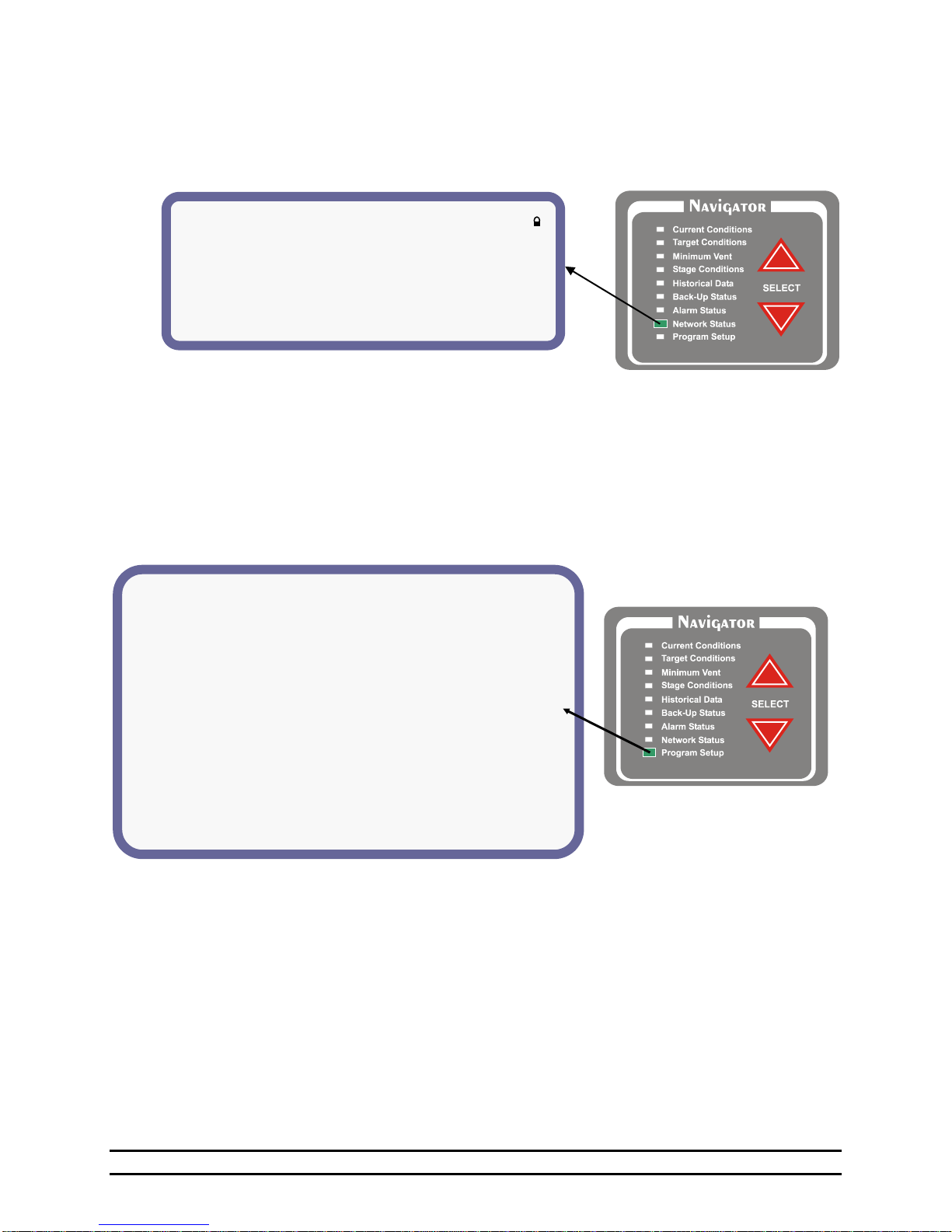
The Network Status shows the installed Evolution Stages, the Back-Up and the Heat Zone. The ENABLED
indicator shows if the stage is enabled and the STATUS indicates OK or Failed.
(1) Modules – The Evolution modules that can be installed will appear here. EV I/O - This is the back
board of the Evolution 3000/3001.
(2) Enabled – Those modules that are enabled will be indicated by Yes. This column lets you know which
modules are turned on for the Evolution control to communicate with. When adding expansion back-up
modules, the ENABLED must be set to “Yes” for proper operation.
(3) Status - OK or Failed. This column lets you know if you have lost communication with one of the
modules.
6.9 Program Set-Up
The Program Setup screen is used to select all of the Programming screens. Highlight an entry and press
the ENTER button. See the next section of this manual for a description of the programming screen.
(1) General Settings – Parameters that usually need to
be set when the system is installed. See Section 7.1.
(2) Temperature Sensors –See Section 7.2.
(3) Feed Level Sensors - See Section 7.3.
(4) Ventilation Inlets - See Section 7.4.
(5) Natural Ventilation - See Section 7.5.
(6) Growout Curve - See Section 7.6.
(7) Tunnel Ventilation - See Section 7.7.
(8)-(11) On/Off Stages - Settings for Set up of stages.
See Section 7.8.
Part No. 4801-5307 Rev 2-15 Evolution 3000 and 3001 24 of 70
(12) Variable Stage Outputs - Set-up for variable
stages. See Section 7.9.
(13) Stage Properties – See Section 7.10.
(14) Setup Feed Clocks – See Section 7.11.
(15) Setup Light Clocks - This feature is added for
those applications that desire light control See
Section 7.12.
(16) Seasonal Programs & Password Setup –
See Section 7.13.
(17) Diagnostics - See Section 7.14.
Page 25
** (1)EV300x v0.32 **
(2)HHNet Address = 1
(3)Optimum Mode = Off
(3)Growout Start Date = 15 Jun 2003
(4)Preheat Mode = Off
(5)Date = 21 Feb 2007
(6)Day = Wed
(7)Time = 05:20p
(8)Units of Measure = English
(9)Pressure Units = Inches of wc
(10)Water Meter-Pulses Per Unit - 100
**SENSOR SETUP**
(1)Room Temperature Sensors = --6-4-2 (2)ALARM on Outside Sensor Error = Off
(3)SENSOR (4)ENABLED (5)VALUE (6)ADJUSTED
1 ON 77.0 + 3.0°
2 ON 77.0° + 1.0°
3 ON 77.0° +00.0°
4 OFF 77.0° +00.0°
5 OFF 77.0° +00.0°
6 OFF 77.0° +00.0°
7 OFF 77.0° +00.0°
8 OFF 77.0° +00.0°
7. Setting Programming Functions
This section discusses the programming screens for the Evolution 3000 and 3001.
7.1 General Settings
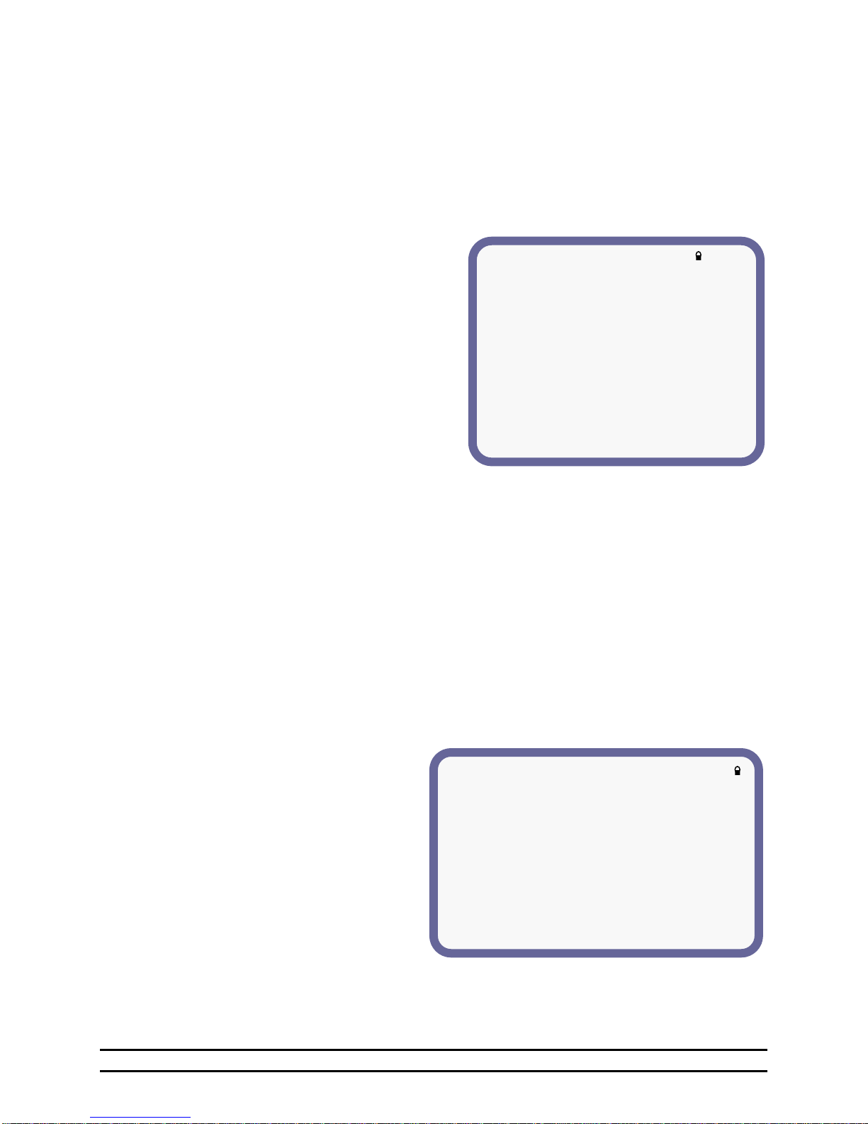
The General Settings contains parameters that usually only need to be set once when the system is installed.
To change any of these parameters, use the EDITOR arrows to navigate through the list and the plus (+) and
minus (-) buttons to increase or decrease the values.
(1) Software Version – The software version currently in use.
(2) HHNET Address - HH.Net permits up to
32 controllers to be addressed on a single
communications port of a personal
computer (PC). In order for the computer
to recognize the communications from the
controllers, each controller must have a
unique network address. For example: If
you have an Evolution 3000 or 3001, a
Stage Master, and two Power Vents you
would need to set the Evolution to address
1, the Stage Master to address 2, the first
Power Vent to address 3, and the second
Power Vent to address 4. Valid settings
are: 1 - 32. (You do not have to address the
controllers in any particular order.)
(3) Optimum Mode – On or Off. Refer to
Section 7.6.2 for a detailed description of
the Optimum Mode features and options.
(4) Growout Start Date - Set the date desired
to start the grow-out. Evolution will use this
date to control the feed, light clock and
ramping functions. NOTE: This must be set
to the first day of grow-out. Your historical
data will start at this date and go for 99 days
or until the next grow-out date has been set
and then that date has been passed.
(5) Preheat Mode – On or Off
(6) Date – The current date as Day/Month/Year.
(7) Day – The current day of the week.
(8) Time – The current time.
(9) Units of Measure - The units of measure can be
selected as English or Metric.
(10) Pressure Units - Pressure units can be selected
as inches of water column or Pascals.
(11) Water Meter-Pulses Per Unit – HH standard
water meter is one pulse per gallon. Select a
value from 1 to 100.
7.2 Temperature Sensors
The Sensor Set-Up screen is used to set the temperature sensors that will be used to determine the internal
temperature of the building.
(1) Room Temperature Sensors - Select any or
all of the internal sensors. Your alarm high
and low limits will use these sensors that are
displayed here.
For example: If you wanted to display
sensors 1,2,3,4,5 for your room temperature
it would look like this: "---54321" If you
turn all the sensors off (by setting it to -) the
control would use the outside temperature
and it would look like this: "Outside-".
(2) Alarm on Outside Sensor Error – On or Off.
(3) Sensor – Identifies up to eight inside and one
outside sensor.
(4) Enabled – Yes or No.
(5) Value – Current temperature reading.
(6) Adjusted – This will indicate if the sensor temperature has been calibrated and the amount of re-calibration.
Part No. 4801-5307 Rev 2-15 Evolution 3000 and 3001 25 of 70
Page 26
**STATIC PRESSURE SETTINGS**
(1)Vent Anticipation = On
(2)Learn Times = Yes
(3)Time before fan starts = 5 s
(4)Time after fan starts = 5 s
(5)Reaction Delay = 5 seconds
(6)Pressure Differential = 0.02
(7)Attic Inlets Installed = Yes
(8)Pressure Ramping = On
(9&10)Target Press. = 0.04 @ High Temp = 84.0°
(11&12)Target Press. = 0.10 @ Low Temp = 72.0°
(13&14) Attic Press. = 0.05 @ Out. Temp = 70.0°
** Feed Level Module Setup **
(1)Bin 1:
(2)Diameter = 6 ft (3)Cap Angle = 30°
(4)# of Rings = 1 (5)Ring Height = 2.67ft
(6)Feed wt: 00 lb (7)Bin ht: 9.07 ft
(8)Bin 2:
(9)Diameter = 6 ft (10)Cap Angle = 30°
(11)# of Rings = 1 (12)Ring Height = 2.67ft
(13)Feed wt: 00 lb (14)Bin ht: 9.07 ft
7.3 Feed Level Sensors
The Feed Level Module Setup screen sets
the parameters required to monitor feed bins.
(1) Bin 1 - These settings provide the feed
level sensor at Bin #1 with necessary
information to calculate the approximate
feed weight and height.
(2) Diameter – Feed Bin #1 diameter = 6,
7, or 9 ft.
(3) Cap Angle – Feed Bin #1 cap angle at
the top of the bin = 30° or 40°
(4) # of Rings – Feed Bin #1 number of rings = 1, 2, 3, 4, or 5
(5) Ring Height - Feed Bin #1 ring height = Measurement from the top/center of one ring to the top/center
of the next ring.
(6) Feed wt - Feed Bin #1 feed weight = The feed weight is calculated by using the entered bin size
information and the current feed level module results.
(7) Bin ht - Feed Bin #1 bin height = The bin height is calculated by using the entered bin size
information.
(8) Bin 2 - These settings provide the feed level sensor at Bin #2 with necessary information to calculate
the approximate feed weight and height.
(9) Diameter – Feed Bin #2 diameter = 6, 7, or 9 ft.
(10) Cap Angle – Feed Bin #2 cap angle at the top of the bin = 30° or 40°
(11) # of Rings – Feed Bin #2 number of rings = 1, 2, 3, 4, or 5
(12) Ring Height - Feed Bin #2 ring height = Measurement from the top/center of one ring to the top/center
of the next ring.
(13) Feed wt - Feed Bin #2 feed weight = The feed weight is calculated by using the entered bin size
information and the current feed level module results.
(14) Bin ht - Feed Bin #2 bin height = The bin height is calculated by using the entered bin size
information.
7.4 Ventilation Inlets
The Static Pressure setting sets the parameters necessary to operate the vents.
(1) Vent Anticipation - When vent
anticipation is turned ON, the vents will
start opening before a negative
ventilation stage turns on and continue to
open until the vent opening necessary for
the desired target pressure is achieved.
(2) Learn Times – When learn times “Yes” is
selected, the controller will automatically
adjust the time (seconds) before and after
the fans turn ON depending on the static
pressure. NOTE: This feature is disabled
in Optimum Mode.
(3) Time before fan starts – The number of
seconds before a negative ventilation
stage turns ON that the vents will start
opening.
(4) Time after fan starts – The number of seconds after a negative ventilation stage turns ON that the vents will
continue to open allowing the fans to increase to full speed.
(5) Reaction Delay – The amount of time delay before the vent machine operates.
(6) Pressure Differential - Number from target to start opening and closing vents.
Example: With Target 0.07 and Differential 0.02, the vents open when the pressure is above 0.08; The
vents will close when the pressure is below 0.06.
(7) Attic Inlets Installed – Select Yes or No; If Attic Inlets are installed, select Yes. Refer to Application
Note # 4809-0011 for complete application details regarding the Inlet Operation with Attic Vents.
Part No. 4801-5307 Rev 2-15 Evolution 3000 and 3001 26 of 70
Page 27

**(1)NATURAL VENTILATION**(Target:70.0°)
(2)Allow Natural Ventilation = No
(3) (4) (5)
Current
Cool
Warm
(6)Temp Diff (In-Out):
( 15° )
30°
5°
(7)Cycle Time
( 2 m )
2 m
3 m
(8)Initial Drop Delay:
(2 cyc)
3 cyc
0cyc
(9)Initial Run Time:
( 42 s)
30 s
60 s
(10)Open Runtime:
( 18 s)
10 s
35 s
(11)Close Runtime:
( 37 s)
41 s
38 s
(12)Aggr Range (+/-):
( 2.6°)
2.0°
5.0°
(13)# (14)SENSORS (15)MODE (16)OPEN (17)CLOSE
U1 --654321 NAT 77.5° 75.0°
U2 --654321 N&T 76.5° 74.0°
(8) Pressure Ramping – Select On or Off to enable or disable pressure ramping.
(9 & 10) Target Press. @ High Temp - The target pressure when the outside temperature is at the high
temperature limit. Set both pressure and temperature limit.
(11 & 12) Target Press. @ Low Temp - The target pressure when the outside temperature is at the low
temperature limit. Set both pressure & temperature limit.
(13 & 14) Attic Pressure – When the Attic Inlets Installed = “Yes” and the conditions allow the Attic Inlets to
be enabled, the target pressure will be the selected pressure when the outside temperature is at the selected
temperature. Set both pressure & temperature. For the controller to allow enabling of the Attic Inlets, first,
the controller must be in Minimum Vent Mode; second, the Attic Inlets become active when either the
Outside Temperature is less than the selected Attic Outside Temperature OR any Heat Stage is activated.
The Attic Inlets will remain active until the averaged house temperature reaches the selected Tunnel OffPoint Temperature. After the Tunnel Off-Point Temperature is reached, the Attic Inlets will be disabled and
remain disabled until any Heat Stage is activated.
NOTE: There are now four inlets: Attic, Sidewall, Tunnel and Tunnel2. Attic and Tunnel2 are optional.
Refer to the diagram in Section 9.1 for connection locations. Attic can be used in the place of U1
Natural and/or Tunnel2 can be used in the place of U2 Natural. The attic vents are able to blend with
the other inlets if too many fans turn on to the point that the attic inlets are all the way open. For
example, if we assume that all inlets are available, the controller will start by using the Attic Inlets. If
enough fans turn on that the Attic Inlets are fully open, the static pressure will be greater than the
target. A timer will start at this point. If conditions stay like this for more than a minute, the
controller will start allowing the sidewall inlets. This same procedure will continue as more fans turn
on until the sidewall inlets are fully open and then it would start blending the tunnel inlet and etc. The
same process happens as fans turn off and the vents become fully closed. If the static pressure stays
below the target for more than a minute, then the controller will shift down to the previous inlet until it
gets down to the lowest level which would be the Attic, if enabled.
7.5 Natural Ventilation
Natural Ventilation options are:
(1) Target Temperature –
Displays the existing
Target Temperature.
(2) Allow Natural Ventilation –
Yes or No. This must be
set to yes before the
control is allowed to enter
into natural ventilation.
(3) Current – This is the value
currently being used
derived from the cool and
warm settings.
(4) Cool – The desired operational settings for a cooler outside temperature.
(5) Warm – The desired operational settings for warm outside conditions which would be very near the
target temperature.
(6) Temp Diff (In-Out) – The Temperature Differential which is the inside target minus the outside
temperature.
(7) Cycle Time – The length of time in minutes between the start of one curtain position adjustment, and
the start of the next curtain position adjustment. ( A Cycle time of 3 means that the curtain will
move up or down, or remain stationary, depending upon temperature for its runtime once every 3
minutes).
(8) Initial Drop Delay – The number of cycles that the curtain will be delayed after the Initial Drop.
(9) Initial Run Time – When the controller determines that the curtains should run open and senses that
they are closed, it uses this parameter for the 'first' run. This setting is used to allow the curtains to
open enough on the first run to guarantee adequate ventilation.
(10) Open Run Time – Period of time the curtain will run open each cycle.
(11) Close Run Time – Period of time the curtain will run close each cycle.
(12) Aggressive Range – If this Temperature limit is exceeded, the run times of the stages are doubled.
Part No. 4801-5307 Rev 2-15 Evolution 3000 and 3001 27 of 70
Page 28

**TEMPERATURE RAMPING**
(1)Number of Points = 10 (2)Ramping = Off
(3)Preheat Target = 95.0° (4)Preheat = Off
(5)Target Temperature Differential
(6)POINT (7)DAY (8)TARGET
1 1 90.0°
2 5 88.0°
3 10 86.0°
4 15 84.0°
5 20 82.0°
6 25 80.0°
7 30 78.0°
8 35 76.0°
9 40 74.0°
10 45 72.0°
NOTE: If the temperature is at the open setting, the control will run the machine for the runtime
you have set. As the temperature moves up, your runtime will also increase. The runtime may
ramp up to two times the selected Run Time depending on the amount of temperature difference
past the Open or Closed set temperatures. As the temperature gets closer to the Aggressive Range
tolerance, the Run Time gets closer to the maximum two times Run Time. Your runtime will have
doubled once the temperature reaches the set Aggressive Range/tolerance. This is also true for the
close side of the curtain machine.
(13) # - Identify either Unit #1 or Unit #2.
(14) Sensors – Identify the sensors used by the controller. This will be the sensor that the curtain machine
will operate from. Active sensors will be indicated by a number starting with #1 from right to left.
Inactive sensors will be indicated by a - or hyphen. When "outside-" is displayed, outside sensor is
active. To use sensors 1,2 and 3, "-----321" should be displayed. See (7).
(15) Mode – Natural (NAT) or Natural Tunnel (N&T). Sets unit 2 to Tunnel Inlet also.
(16) Open –This will be the temperature at which your curtain will open for natural ventilation.
(17) Close - This will be the temperature at which your curtain will close from natural ventilation and start
it back to minimum ventilation.
7.6 Growout Curve
The Growout Curve is used to adjust the temperatures and/or minimum vent requirements automatically by
the grow-out day. The specific Growout Curve screen features and setting options will depend on whether
the Optimum Mode feature is turned ON or OFF. The Optimum Mode feature is selected by entering
“Program Setup” and then “General Settings”. Refer to Section 7.1.
7.6.1 Growout Curve With Optimum Mode OFF
(1) Number of Points –Select 2 through
10 points.
(2) Ramping – Select On or Off to
enable or disable ramping.
(3) Preheat Target – Target
Temperature for preheating.
(4) Preheat – On or Off. Preheat allows
the controller to run the target to a
higher set target temperature for
preheating the house.
Part No. 4801-5307 Rev 2-15 Evolution 3000 and 3001 28 of 70
Page 29
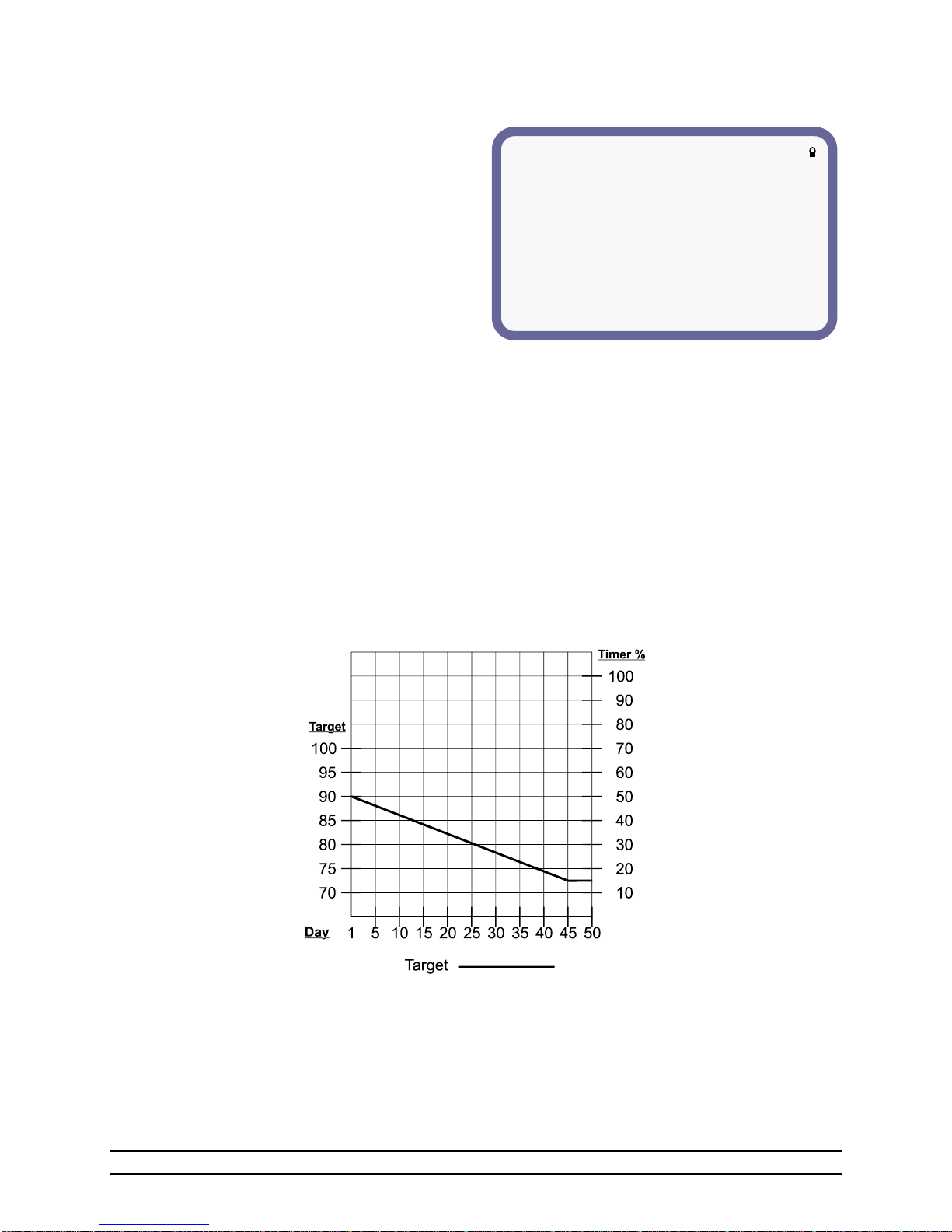
TARGET TEMPERATURE DIFFERENTIAL
(a)Enabled = Yes
(b)Target Adjust = +5.0°
(c)Adjust Between 11:00a and 1:00p
(5) Target Temperature Differential – When enabled, this feature will adjust the target temperature
either higher or lower by the selected number of degrees during the selected time of day.
a. Enabled – Select Yes to enable or
No to disable Target Temperature
Differential.
b. Target Adjust – The desired
degrees above or below the Target
Temperature.
c. Adjust Between – The selected time
of day for which the Target
Temperature Differential will occur.
IMPORTANT: Ramping MUST be enabled
for this feature to operate.
At the start of the specific time range “Adjust Between” entered, the Target Temperature will be
adjusted at a rate of 0.5° per minute until it reaches the total adjustment “Target Adjust” entered. The
same applies when it is at the end of the “Adjust Between” period and is returning to the days original
Target Temperature.
For example, this feature can be used to allow drops in temperature during a Feed Cycle. It could also
be used in the summer to insure that the building remains in Tunnel Ventilation well after dark in an
attempt to relieve the stress after a long hot day.
(6) Point –This table identifies the specific points. You are allowed up to 10 points at which you can
change the target at these points. This allows you to keep the same target for a couple of days and then
start ramping down. When the target temperature changes in the Target column, that target will start the
day that is in the Growout day column.
(7) Day – The day of growout that starts the set Target Temp.
(8) Target – Set the specific target temperature for each of the growout days.
NOTE: The graph below shows an example of how the EV would adjust the target temperature based on
the growout day.
Part No. 4801-5307 Rev 2-15 Evolution 3000 and 3001 29 of 70
Page 30

**OPTIMUM GROWOUT CURVE**
(1)Number of Points = 10 (2)Ramping = Off
(3)Preheat Target = 95.0° (4)Preheat = Off
(5)Target Temperature Differential
(6)Max Reduction of Opt%: 50%
HEAT
TUNNEL
OPTIMUM TIMERS
(7)DAY
(8)TARGET
(9)AJST
(10)AJST
(11)FANS
(12)BASE%
(13)ACTIVE
1
90.0°
- 0.0°
+ 0.0° 2 10%
--6-4---
5
88.0°
- 0.0°
+ 0.0° 2 10%
--6-4---
10
86.0°
- 0.0°
+ 0.0° 3 10%
--6-4---
15
84.0°
- 0.0°
+ 0.0° 3 10%
--6-4---
20
82.0°
- 0.0°
+ 0.0° 4 10%
--6-4---
25
80.0°
- 0.0°
+ 0.0° 5 10%
--6-4---
30
78.0°
- 0.0°
+ 0.0° 6 10%
--6-4---
35
76.0°
- 0.0°
+ 0.0° 7 10%
--6-4---
40
74.0°
- 0.0°
+ 0.0° 8 10%
--6-4---
45
72.0°
- 0.0°
+ 0.0° 9 10%
--6-4---
TARGET TEMPERATURE DIFFERENTIAL
(a)Enabled = Yes
(b)Target Adjust = +5.0°
(c)Adjust Between 11:00a and 1:00p
7.6.2 Growout Curve With Optimum Mode ON
If Optimum Mode is enabled, the grow-out curve screen will expand to the following form. In addition to
the Target Temperature Curve, the table expands to include a Heat Adjustment (HEAT AJST), a Tunnel
Adjustment (TUNNEL AJST), a maximum number of tunnel fans, a minimum runtime percentage, and a
minimum vent level. These allow the grower more automation when it comes to setting up their controller
for the entire grow-out.
(1) Number of Points –Select 2 through 10 points.
(2) Ramping – Select On or Off to enable or disable ramping.
(3) Preheat Target – Target Temperature for preheating.
(4) Preheat – On or Off. Preheat allows the controller to run the target to a higher set target temperature
for preheating the house.
(5) Target Temperature Differential – When enabled, this feature will adjust the target temperature
either higher or lower by the selected number of degrees during the selected time of day.
a. Enabled – Select Yes to enable or
No to disable Target Temperature
Differential.
b. Target Adjust – The desired
degrees above or below the Target
Temperature.
c. Adjust Between – The selected
time of day for which the Target
Temperature Differential will
occur.
IMPORTANT: Ramping MUST be
enabled for this
feature to operate.
At the start of the specific time range “Adjust Between” entered, the Target Temperature will be
adjusted at a rate of 0.5° per minute until it reaches the total adjustment “Target Adjust” entered.
The same applies when it is at the end of the “Adjust Between” period and is returning to the days
original Target Temperature.
For example, this feature can be used to allow drops in temperature during a Feed Cycle. It could
(6) Max Reduction of Opt% – The Evolution 3000/3001 can reduce the optimum timers run time when
(7) Day –This table identifies the specific days of growout that starts the Target Temp. You are allowed
also be used in the summer to insure that the building remains in Tunnel Ventilation well after dark
in an attempt to relieve the stress after a long hot day.
the outside temperature falls below room temperature. This value is the maximum reduction allowed
for this feature. The maximum is reached when the outside temperature is 40 degrees F below room
temperature. From 0% up to 50% may be selected.
up to 10 points at which you can change the target at these points. This allows you to keep the same
Part No. 4801-5307 Rev 2-15 Evolution 3000 and 3001 30 of 70
Page 31

target for a couple of days and then start ramping down. When the target temperature changes in the
Target column, that target will start the day that is in the Growout day column.
(8) Target – Set the specific target temperature for each of the growout days. The target temperature
ramps between growout days.
(9) Heat Adjust – Set the specific heat adjustment for each of the growout days. A young flock requires
a tightly controlled and heated environment. As the flock grows older, heat is less important. The
Heat Adjust feature ramps between growout days and saves heating costs by allowing the heaters to
run less frequently and only turn on at cooler temperatures as the flock grows older. The Heat Adjust
is the set amount (-x.xº) below the heat stages ON point at which the heat stages will operate. Refer to
the following example charts and figures.
(10) Tunnel Adjust – Set the specific tunnel adjustment for each of the growout days. Older flocks
require a tightly controlled and more cooled environment. As the flock grows older, fan cooling is
more important. The Tunnel Adjust ramps between growout days and is the set amount (-x.xº) above
the tunnel temperature at which the controller will allow tunnel ventilation.
NOTE: The ON point for all cool tunnel stages will also be increased by this amount.
Refer to the following example charts and figures.
(11) Tunnel Fans – The desired maximum number of Tunnel Fans which are allowed to turn On for the
specific growout day. This refers to stages programmed as Cool Negative Tunnel or Cool Tunnel.
(12) Optimum Timers Base % – Set the specific minimum vent run % for each of the growout days.
The Run % is the percentage of the Minimum Timer Cycle that the stage will run. This percentage
ramps between growout days.
(13) Optimum Timers Active – This setting is used in conjunction with the 8 optimum timers. In addition
to each stage being able to operate on a Min1, Min2, VAR, or Cool Timer, they now also have the
option of being programmed to use an Optimum Timer (OPTX). These are labeled as OPT1, OPT2,
…., OPT8. This setting relates to which of these OPTx timers are allowed to operate at this time.
The OPTx timer uses the optimum timer percentage that is calculated by the controller with the run%
being its minimum. This setting allows the user to add additional fans to their minimum ventilation as
the animals age or even change fans completely.
NOTE: The following graphs and figure shows examples of how the EV Optimum Mode would adjust the
target, heat, and tunnel temperatures, minimum run %, and vent level based off of the growout
days and target temperatures.
Part No. 4801-5307 Rev 2-15 Evolution 3000 and 3001 31 of 70
Page 32
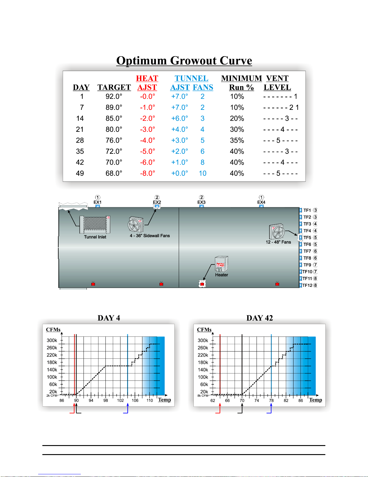
Target
Tunnel
Adjust
Heat
Adjust
Target
Tunnel
Adjust
Heat
Adjust
EXAMPLE OF
Part No. 4801-5307 Rev 2-15 Evolution 3000 and 3001 32 of 70
Page 33
**TUNNEL SETUP**((1)Target = 75°)
(2)Tunnel Enabled = ON
Tunnel (3)Sensors Temperature
On (4)---54321 (5)85.0°
Off (6)-----3-1 (7)80.0°
(8)Use Tunnel Target Pressure = No
(9)Natural Unit #2 is Tunnel Inlet = No
(10)Enable Low Pressure Alarm in Tunnel = Yes
(11)Increase High Temp Limit +2.0 in Tunnel
(12)Tunnel Timeout = 30:00 (13)(30:00 max)
7.7 Tunnel Ventilation
The Tunnel Setup screen sets the parameters necessary to operate in the Tunnel mode.
(1) Target – Displays the target temperature
of the building.
(2) Tunnel Enabled – Select either
Yes or No to enable or
disable going into the Tunnel
mode.
(3) Sensors – The user is given the
choice as to what sensors will
be used to enter and exit
Tunnel Mode; select any or all
of the available sensors. To
use the outside sensor when
entering tunnel set the sensors
to display the word “outside”
by turning all the sensors off.
(4) Tunnel „On Sensors‟ – Selectable for 1-8 sensors. Select the sensors used for entering Tunnel Mode.
(5) Tunnel „On Temperature‟ – The temperature at which the controller will go into tunnel mode.
(6) Tunnel „Off Sensors‟ – Selectable for 1-8 sensors. Select the sensors used for exiting Tunnel Mode.
(7) Tunnel „Off Temperature‟ - The temperature at which the controller will go out of tunnel mode.
(8) Use Tunnel Target Pressure – Yes or No. This will allow a different Target Pressure to be used in the
Tunnel mode.
(9) Natural Unit #2 is Tunnel Inlet – Yes or No. This indicates that PowerTrak Number 2 of the Natural
Set is a Tunnel inlet and will open during Tunnel.
(10) Enable Low Pressure Alarm in Tunnel – Yes or No. Set to Yes if it is desired to use a low pressure
alarm while in the tunnel mode.
(11) Increase High Temperature Limit +##° in Tunnel –While in the tunnel mode the Evolution 3000
can adjust the High Temperature Limit. Enter the number of degrees that the limit is to be
increased while in the tunnel mode. This increase will only be used while in tunnel.
(12) Tunnel Timeout – This feature prevents the controller from flip-flopping in and out of tunnel and also
provides a means for the controller to retry tunnel ventilation after a tunnel error. The Tunnel
Timeout counter forces the controller to wait the selected number of Tunnel Timeout Maximum
minutes between tunnel initiation. For example, if the controller is in tunnel and an error occurs,
the controller will reload the tunnel timeout, exit tunnel ventilation, and sound the alarm. After the
tunnel timeout expires, the controller will reset the tunnel error, turn off the alarm, and if the
conditions allow, retry tunnel ventilation. The tunnel timeout will be reset during a power-on reset
or if the Tunnel Enable is toggled from off to on. As long as the Tunnel Timeout displayed value
is equal to the Tunnel Timeout Maximum displayed value, tunnel ventilation is allowed. If it is in
process of counting, then it is not allowing tunnel ventilation at this time due to a previous error or
because it has recently made an attempt.
(13) Tunnel Timeout Max – Selectable from 10 to 30 minutes in increments of 5 minutes. This setting is
the number of minutes that the Tunnel Timeout counter will count before allowing reentry into
tunnel ventilation.
Part No. 4801-5307 Rev 2-15 Evolution 3000 and 3001 33 of 70
Page 34
NOTE: Highlight and press ENTER to
bring up details on each stage.
**ON/OFF STAGES** ((1)Target = 73.0°)
(2)# (3)SENSORS (4)MODE (5)ON (6)OFF (7)TIMER
1 -------1 Feed 76 74 None
2 Light Ramp
3 -----321 Cstir 76 74 Min 2
4 -------1 Cneg 76 74 Min 1
5 ------2- CNeg 77 75 None
6 -----3-- CNeg 78 76 None
7 ------2- CNeg 79 77 None
8 -------1 CNeg 80 78 None
9 -------1 CNeg 81 79 None
7.8 ON/OFF Stages
You must select the set of stages you
want to set or edit. NOTE: When
programming stages you are allowed to
edit the settings from the main screen.
You are also allowed to go into each
stage and see a detailed screen. To do
this have a stage number highlighted
and then press enter.
(1)Target – Displays the current set
Target Temperature.
(2) Stage # - Stage Numbers.
(3) Sensors – The sensors which may be
used to control the ON or OFF
point of a stage. Sensors 1 thru
8 may be selected or unselected
for each stage. The specific
stage will operate from the
selected sensor/sensors.
Active sensors will be indicated by a number starting with #1 from right to left. Inactive sensors
will be indicated by a - or hyphen. When "outside-" is displayed, the outside sensor is active. To
use sensors 1,2 and 3, "-----321" should be displayed.
(4) Mode – This mode column will indicate how the stage is Programmed to operate.
(OFF) Disables stage from operating during automatic operation.
(Heat) Heat Mode: This method of heating only operates when the curtains are in the closed
position and the operating sensor is below the on temperature.
(CSTIR) Cool Stir Mode: This mode setting allows the cool stage to run whether the main curtain
is open or closed.
(CNEG) Cool Negative: Method of ventilation where air is drawn out of the building by fans,
creating a negative static pressure which draws air into the house from all openings at a
even pace. Will not operate in Tunnel or Nat.
(CNEGT) Cool Negative Tunnel: A combination of the Cool Negative and the Cool Tunnel
Modes.
(CTUN) Cool Tunnel: Only operate during Tunnel operation with one exception being set as a
minimum ventilation timer which will allow the stage to operate on a timer only, in
minimum or power ventilation.
(LIGHT) The LIGHT Mode: See Section 7.12.
(FEED) The FEED mode: See Section 7.11.
(CEVAP) Cool Evaporative mode: See Section 7.10.6
(CHEAT) Cooler Heat mode: Heat stage for the Cooler.
(CCOOL) Cooler Cool mode: Cool stage for the Cooler.
(CHUM) Cooler Humidity mode: Humidifier for the Cooler.
(5&6) ON/OFF –The ON column will indicate the current setting for the onpoint temperature of the stage.
Set this to the temperature you would like for the stage to come on at. The OFF column will
indicate the current setting for the offpoint temperature of the stage. Set this to the temperature you
would like for the stage to turn off at.
(7) TIMER – None, Min1, Min2, Var, Cool, OPT1-OPT8 This Timer column will indicate what type of
timer you want the stage to operate from. If the stage doesn't need a timer then you must have this
setting to none.
Part No. 4801-5307 Rev 2-15 Evolution 3000 and 3001 34 of 70
Page 35
**VARIABLE STAGES**((1)Target: 77.5°)
(2)# (3)SENSORS (4)MODE (5)MaxON (6)MinON (7)CURVE (8)TIME
1 -------1 Light Ramp
2 -------1 Cstir 76.2° 74.0° Fan 4 None
NOTE: Highlight and press ENTER
to bring up details on each stage.
(1) ON/OFF Stage 1 (Target: 70.0)
(2) Sensor(s)= -----------1
(3) Mode = Cool Evap
(4) Timer = None
(5) On/Point = 70.4
(6) OffPoint = 70.0
7.8.1 On/Off Stage Details
(1) ON/OFF STAGE # – Stage number.
(2) Sensor(s) – Sensors used.
(3) Mode –See Section 7.8.
(4) Timer –See Section 7.8.
(5) On/Point – See Section 7.8.
(6) OffPoint –See Section 7.8.
7.9 Variable Stage Outputs
(1) Target – Displays the
target
temperature.
(2) # - Identifies the
Variable Stage
unit below.
(3) Sensors –The selected sensor(s) to operate. Active sensors will be indicated by a number starting with
#1 from right to left. Inactive sensors will be indicated by a - or hyphen. When "outside-" is
displayed, outside sensor is active. To use sensors 1,2 and 3, "-----321" should be displayed.
(4) Mode – CSTIR, CNEG, CNEGT, CTUN, LIGHT. NOTE: This mode column will indicate how the
stage is Programmed. You are allowed to set any stage at any of these modes. When the stage is
used to control lighting then you must set the mode and curve to Light.
(5) MaxON –This MaxON column will indicate the current setting for the Maximum onpoint temperature
of the stage. Set this to the temperature you would like for the stage to reach the desired maximum
speed.
(6) MinON – This MinON column will indicate the current setting for the Minimum onpoint temperature of
the stage. Set this to the temperature you would like for the stage to start running its minimum
speed setting. Minimum speed setting is set at the Minimum Vent screen of the Navigator.
(7) Curve – This is the motor curve for the variable speed fans. If you are using the stage for lights then
make sure the curve is set for light.
Light Run lights. Sets light intensity to vary linearly with time.
Fan 1 For use with Cumberland’s line of Funnel Flow fans that are 24” or less. Also, line
voltage must be single phase.
Fan 2 For operation of 36” fans. The power distributed at each percentage is somewhat
greater than that of Curve 1. Therefore, the speed will be a little greater than that of
Curve 1.
Fan 3 For 3-Phase systems. Its purpose is to shift the voltage curve to give a much higher
power from the varied phase. Conditions that would warrant the use of this curve is a
variable speed fan that varies a great deal from 100% speed to 95% speed.
Fan 4 For 3-Phase systems. Its purpose is to shift the voltage curve to give much less
power from the varied phase. Conditions that would warrant the use of this curve is a
variable speed fan that varies very little from 100% speed to 5% speed.
Fan 5 For use with Cumberland’s newest Emerson fan motor, these motors are typically
used on fans that are 24” or smaller.
(8) Time - None, Min1, Min2, Var, Always ON. This Timer column will indicate what type of timer you
want the stage to operate from. If the stage doesn't need a timer then you must have this setting to
none. Always ON sets the fan to always run at Minimum speed when operating temperature is
below the set Minimum ON temperature.
Part No. 4801-5307 Rev 2-15 Evolution 3000 and 3001 35 of 70
Page 36
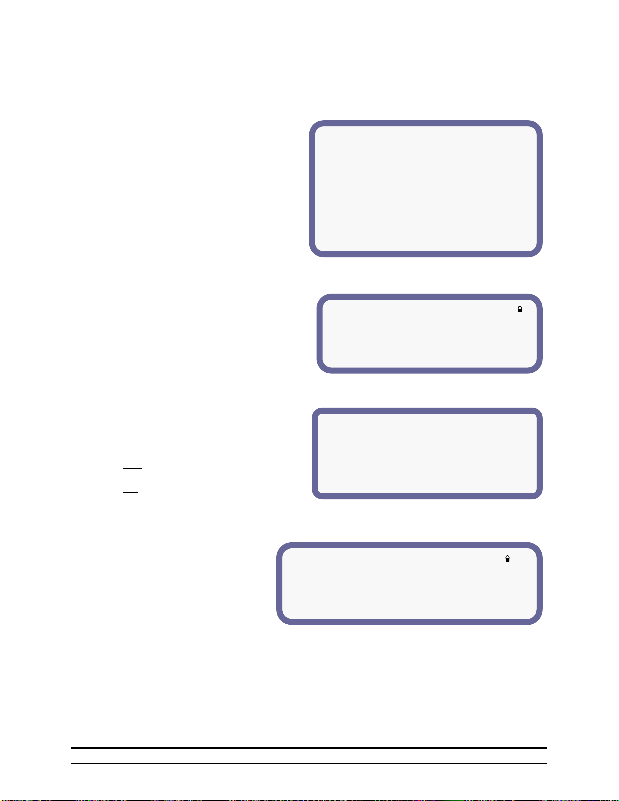
** Cool Negative Properties **
These stages typically operate sidewall fans
Since they are not allowed to operate during
Tunnel Ventilation.
(1) Transitional Stage Override = Yes
(2) Override on Stage # 16
** Stage Properties **
(1)Heat Properties
(2)Cool Stir Properties
(3)Cool Negative Properties
(4)Cool Negative Tunnel Properties
(5)Cool Tunnel Properties
(6)Cool Evaporative Properties
(7)Natural Ventilation Properties
** Heat Properties **
Heat Stages operate heating devices
such as heaters or brooders. The
following are additional properties.
Operate during Minimum Vent only = No
** Cool Stir Properties **
These stages typically operate fans
That are used to stir the air inside
The building. They operate in all
Ventilation modes.
(1)Allow to operate in Tunnel = No
7.10 Stage Properties
The Stage Properties screen is where you link to set up specific parameters for the heating and cooling
modes.
Stage Properties gives you a definition of how a stage will operate and allows you to add additional
variables to some of the properties.
(1)Heat Properties – See Section 7.10.1
(2)Cool Stir Properties – See Section 7.10.2
(3)Cool Negative Properties – See Section
7.10.3
(4)Cool Negative Tunnel Properties – See
Section 7.10.4
(5)Cool Tunnel Properties – See Section
7.10.5
(6) Cool Evaporative Properties - See Section
7.10.6
(7) Natural Ventilation Properties - See
Section 7.10.7
7.10.1 Heat Properties
There is one heat property to be setup. Set
to “Yes” if it is desired to operate the heat
stage only during minimum ventilation.
Otherwise the control will allow a heat stage
to operate at the same time a cool stage is
operating if they are looking at different
sensors.
7.10.2 Cool Stir Properties
This allows stir fans to act as mixing fans during
tunnel ventilation.
(1) Allow to operate in Tunnel – Select Yes or
No.
YES = The stir fans operate in any
ventilation mode.
NO = The stir fans will NOT operate during
tunnel ventilation.
7.10.3 Cool Negative Properties
The following parameters can be set:
(1) Transitional Stage Override –
Yes or No
(2) Override on Stage – Set to an
available Stage Number.
This feature is used to turn Cool
Negative Fans off before entering
tunnel ventilation.
Functionality: When the Override is set (Override on Stage # XX ) to a specific Cool Negative Tunnel
Stage, the Stage turns all of the Cool Negative Fans OFF when the Stage comes ON.
Example: Turning 36” Sidewall Fans OFF when a 48” Negative Tunnel Fan comes ON while still pulling
air through the vent boards.
Part No. 4801-5307 Rev 2-15 Evolution 3000 and 3001 36 of 70
Page 37
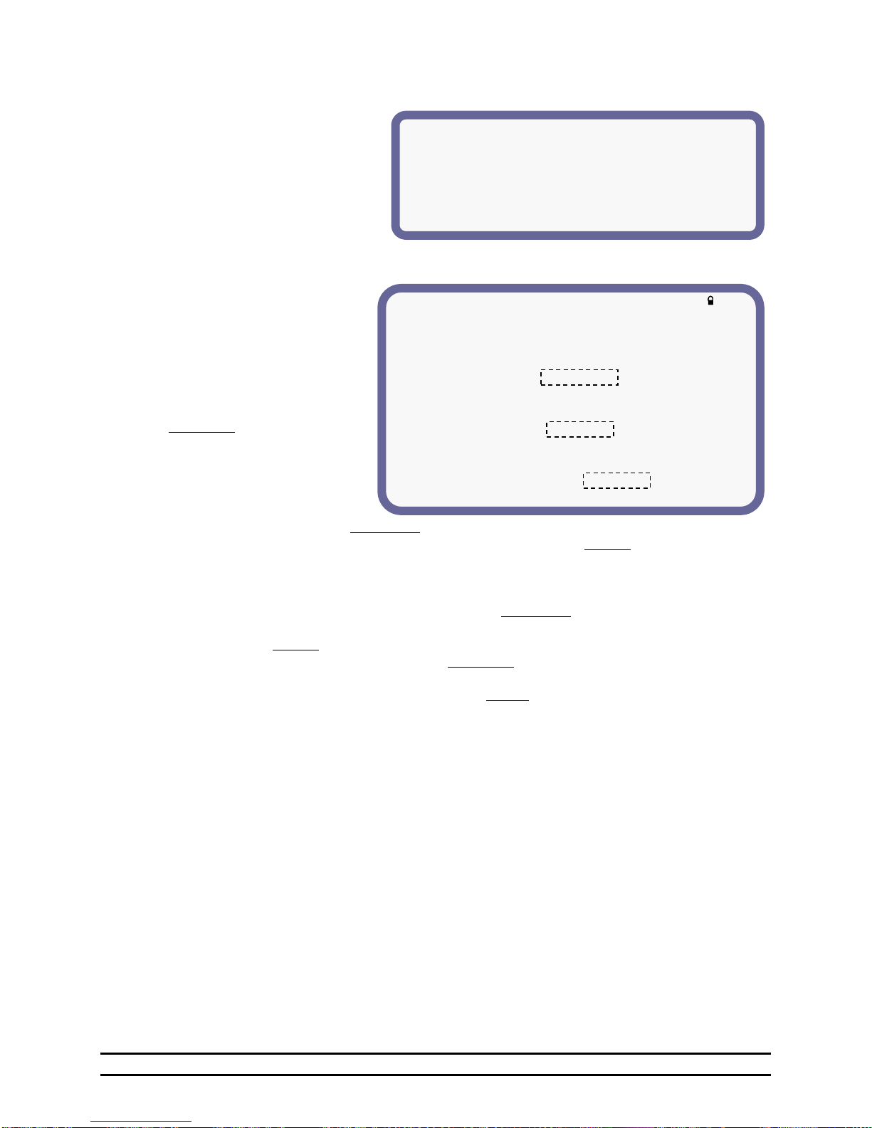
** Cool Negative Tunnel Properties **
These stages typically operate endwall
fans since they are allowed to operate during
both Power and Tunnel Ventilation.
** Cool Tunnel Properties **
These stages typically operate endwall fans
only needed for tunnel Ventilation.
The following are additional properties:
(1)Time Override:
Allow to operate Only While
Time falls between: 2:00p - 2:20p
(2)Growout Day Override:
Allow to operate Always
Growout day > 14
(3)Outside Temperature Override:
Allow to operate Always
Outside Temperature > Target +10.2°
7.10.4 Cool Negative Tunnel Properties
There are no additional parameters
that can be set under this property
display.
7.10.5 Cool Tunnel Properties
The Cool Tunnel Properties
provide for setting override
functions. Take note when setting
the properties. All options must be
true before the stage is allowed to
operate.
For example if all options are set
to Only While, then all options
will have to be true or in the range
before the stage is allowed to
operate. NOTE: Override
parameter settings are "Only
While" and "Always".
(1) Time Override – When set to Only While, the Time Override will allow the stages to operate only
while the time is between the times you set. Otherwise when set to Always, the time will not affect
the stages.
(2) Growout Day Override – During the first days of the growout period, especially during brooding, the
Evolution 3000 or 3001 can be set to only allow the cool tunnel stages to operate after a specified
number of days in the growout period. When set to Only While, the Growout Day Override will
allow the stages to operate only while the growout day is greater than the day you set. Otherwise
when set to Always, the day of growout will not affect the stages.
(3) Outside Temperature Override - When set to Only While the Outside Temperature Override will
allow the stages to operate only while the outside temperature is greater than the target plus or
minus the desired setting. Otherwise when set to Always the outside temperature will not affect the
stages.
Part No. 4801-5307 Rev 2-15 Evolution 3000 and 3001 37 of 70
Page 38
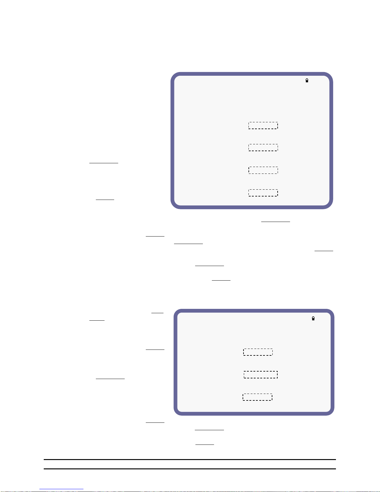
** Cool Evaporative Properties **
These stages typically operate
Evaporative Cooling Systems. The
following are additional properties:
(1)Only Operate During Tunnel Vent = No
(2)Time Override:
Allow to Operate Always
Time falls between 12:00p - 5:00p
(3)Humidity Override:
Allow to Operate Always
Humidity < 75%
(4)Growout Day Override:
Allow to Operate Always
Growout Day > 14
(5)Outside Temperature Override
Allow to Operate Always
Outside Temperature > Target +10.2°
** Natural Ventilation Properties **
The Natural Ventilation Stages typically
operate sidewalls. The following are some
additional properties:
(1)Time Override:
Allow to Operate Always
Time falls between 5:00p - 5:00a
(2)Growout Day Override:
Allow to Operate Only While
Growout Day > 7
(3)Outside Temperature Override
Allow to Operate Always
Outside Temperature > Target +10.2°
7.10.6 Cool Evaporative Properties
Cool Evaporative Properties allow for setting several override functions. Take note when setting the
properties. All options must be true before the stage is allowed to operate.
For example if all options are set to Only While, then all options will have to be true or in the range before
the stage is allowed to operate.
(1) Only Operate During Tunnel
Vent –Setting this to “Yes”
will only allow the
evaporative cooling stages to
operate during tunnel.
Otherwise on “No” will
allow the stages to operate
while not in tunnel. For
example on misting Hogs
during natural ventilation.
(2) Time Override – When set to
Only While, the Time
Override will allow the
stages to operate only while
the time is between the times
you set. Otherwise when set
to Always, the time will not
affect the stages.
(3) Humidity Override - Run while humidity is less than XX%. When set to Only While, the Humidity
Override will allow the stages to operate only while the humidity is less than the humidity you set.
Otherwise when set to Always, the humidity will not affect the stages.
(4) Growout Day Override - When set to Only While, the Growout Day Override will allow the stages to
operate only while the growout day is greater than the day you set. Otherwise when set to Always,
the day of growout will not affect the stages.
(5) Outside Temperature Override - When set to Only While, the Outside Temperature Override will
allow the stages to operate only while the outside temperature is greater than the target plus or
minus the desired setting. Otherwise when set to Always, the outside temperature will not affect
the stages.
7.10.7 Natural Ventilation Properties
(1) Time Override - When set to Only
While, the Time Override will
allow the Natural Curtain
Stages to open while the time
is between the times you set.
Otherwise when set to Always,
the time will not affect the
Natural Curtain Stages.
Part No. 4801-5307 Rev 2-15 Evolution 3000 and 3001 38 of 70
(2) Growout Day Override - When set
to Only While, the Growout
Day Override will allow the
Natural Curtain stages to
operate only while the growout
day is greater than the day you
set.
Otherwise when set to Always, the day of growout will not affect the stages.
(3) Outside Temperature Override - When set to Only While, the Outside Temperature Override will
allow the stages to open only while the outside temperature is greater than the target plus or minus
the desired setting. Otherwise when set to Always, the outside temperature will not affect the
stages.
Page 39
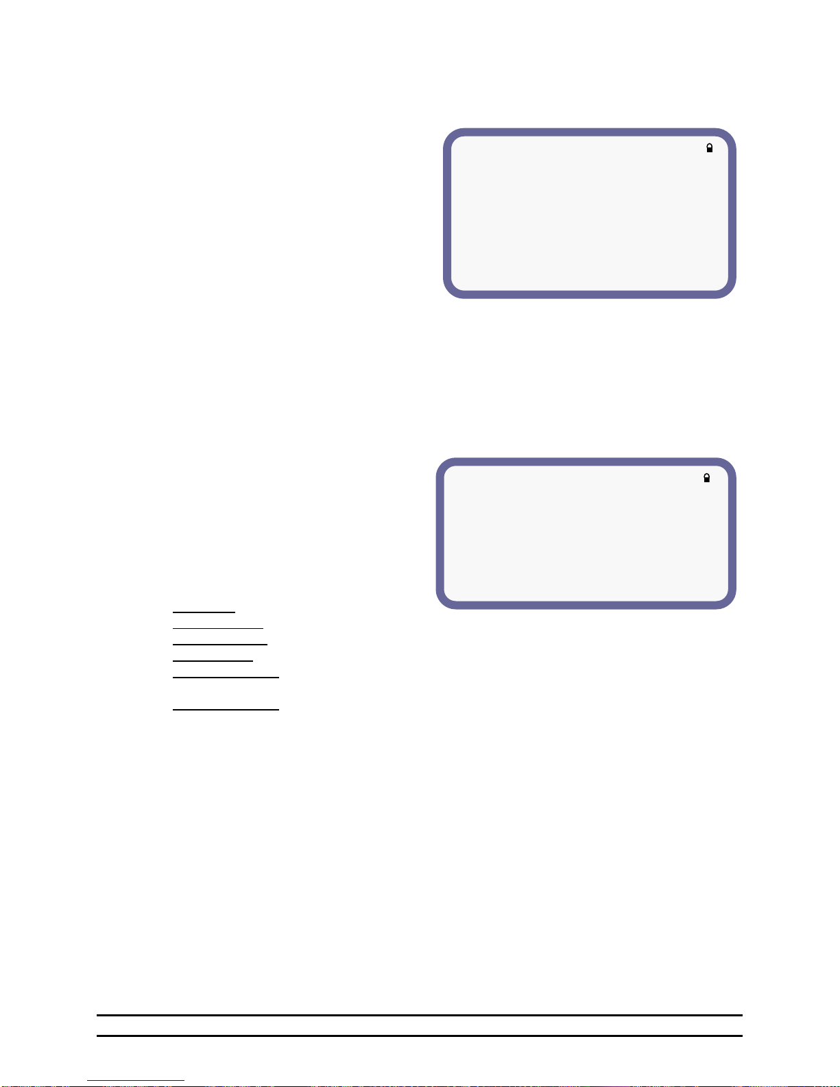
**FEED CLOCK SETUP**
(1)Feed Cycle Light Override = No
(2)Feed Cycle Light Intensity = 25%
(3)Growout Schedules Used by Ramp = 1-4
(4)Schedule (5)START DAY
1 1
2 7
3 14
4 21
5 28
(1)Feed Schedule: 1
(2)Start Day = 1
(3)Number of On/Off Cycles = 3
(4)Days in Operation = Every Day
(5)Choose Days = SMTWTFS
(6)CYCLE (6)START (7)RUNTIME
1 12:00a 1:30
2 5:00a 1:00
3 12:00p 1:00
7.11 Feed Clock Setup
The Feed Clock Setup establishes the parameters necessary to enable automatic feed control functions.
(1) Feed Cycle Light Override – Turns the lights
to a set intensity while running the feed
program.
(2) Feed Cycle Light Intensity – Sets the light
intensity percentage to occur during the feed
cycle.
(3) Growout Schedules Used by Ramp - Set the
number of growout schedules up to five.
(4) Schedule – The schedule number will
automatically be set by Evolution.
(5) Start Day - Displays the growout day on which
the selected schedule will start. The Start Day
is settable on the Schedule screen.
7.11.1 Feed Clock Schedules
The Feed Clock Schedules screen contains options for the feeding period daily cycles, skip days and
runtimes.
Select the individual schedules in the Feed Clock Setup screen.
This screen is also available from the Target Conditions screen as described in Section 6.2.
(1) Feed Schedule – The feed schedule selected from the Feed Clock Setup screen will appear here.
(2) Start Day – Set the growout day in which the
specific schedule starts.
(3) Number of On/Off Cycles – Enter the number
of On/Off cycles desired (up to ten).
(4) Days in Operation – This setting is used for
special feeding cycles running the feed only
every other day if set to odd or even days.
Enter the desired Days In Operation option for
operating growout days.
Every Day – No days skipped.
Odd Days Only – Runs the feed cycles ONLY on the ODD growout days (1, 3, 5, 7, etc.).
Even Days Only – Runs the feed cycles ONLY on the EVEN growout days (2, 4, 6, 8, etc.).
Selected Days – Runs the feed cycles only on the selected days chosen in item 5.
Two On / One Off – The feed clocks will be allowed to operate two days straight starting on Day 1 of
the growout then it will be off for one day. The cycle will then repeat for the entire growout.
One On / Two Off – The feed clocks will be allowed to operate one day starting on Day 3 of the
growout and be off for the next two days. The cycle will then repeat for the entire growout.
(5) Choose Days – Select the specific days for operation. Used only when Days In Operation item 4 is set
to “Selected Days”.
(6) Cycle – This identifies the feed cycle.
(7) Start – Enter the start time in hours and minutes of the feed schedule cycle.
(8) Runtime – Enter the length of time in hours and minutes for the feeding cycle.
Part No. 4801-5307 Rev 2-15 Evolution 3000 and 3001 39 of 70
Page 40
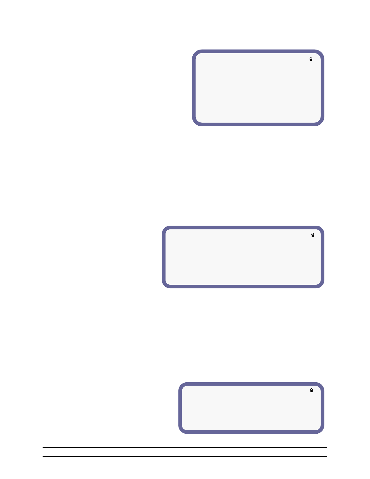
**LIGHT CLOCK SETUP**
(1)Feed Cycle Light Override = No
(2)Feed Cycle Light Intensity = 25%
(3)Growout Schedules used by Ramp 1-4
(4)SCHEDULE (5)START DAY
1 1
2 17
3 19
4 22
5 25
(1)Light Schedule: 4
(2)Start Day = 22
(3)Number of On/Off Cycles = 4
(4)CYCLE (5)START (6)RUNTIME (7)INTENSITY (8)RAMP
1 12:00a 2:00 75% 0:10
2 10:00a 2:00 100% 0:10
3 5:00p 2:00 100% 0:10
4 10:00p 2:00 100% 0:10
**PROGRAMS & SECURITY**
(1)Seasonal Program = 1
(2)Program Name = PROGRAM1
(3)Copy to Program = 2 (4)Enter to Proceed
(5)Change Password
4
7.12 Light Clock Setup
The Light Clock Setup establishes the parameters
necessary to enable automatic control of the
house lights. On each Schedule you will need to
program a start day of when you want the control
to start using this schedule. Then you will need
to set the number of on/off cycles. This is how
many times the light clock needs to come on in a
24-hour period. You are allowed 10 on/off
cycles. Then you set the start time of each cycle
and how long that cycle needs to run. When you
are using a variable speed stage for the lights you
are allowed to set the intensity and ramp.
The intensity is the level you want the lights to be on when your cycle comes on. The ramp allows the light
ramp up and down from off to the intensity you have set. The ramp applies at the beginning and the ending
of the light cycle.
(1) Feed Cycle Light Override - Turns the lights to a set intensity while running the feed program.
(2) Feed Cycle Light Intensity – Set the light intensity percentage to occur during the feed cycle.
(3) Growout Schedules used by Ramp 1-1- Set the number of schedules from one up to five. The next
schedule will start after you have reached the growout day that your schedule starts on.
(4) Schedule – The schedule number will automatically be set by Evolution. After the number of Schedules
have been set you will need to setup each schedule.
(5) Start Day –The starting day of each schedule.
7.12.1 Light Clock Details
Select the individual cycle in the
Light Clock Details screen and enter
the start day time that lighting is to
begin and the length and intensity of
the lighting period. This screen is
also available from the Target
Conditions screen as described in
Section 6.2.
(1) Light Schedule – The selected
schedule.
(2) Start Day – Set to the growout day to start program.
(3) Number of On/Off Cycles – Enter the number of On/Off cycles desired (up to ten).
(4) Cycle –The selected cycle within the schedule.
(5) Start – The start time of the lighting cycle.
(6) Runtime- The runtime of the lighting cycle. (hours : minutes)
(7) Intensity –Set the intensity of the lights from 0% to 100%. (For use with variable units only).
(8) Ramp – If it is desired to ramp the lights, that is to slowly turn the lights on and off, enter the time
period (hours:minutes) over which to turn the lights on and off (For use with variable units).
7.13 Seasonal Programs & Password Setup
The Seasonal Programs & Password Setup screen is used to change programs, copy the settings of one
program into another program or set the password to access applicable screens.
(1) Seasonal Programs – Select Program 0,
1 or 2 for the current operating program.
This selection can also be used to
Part No. 4801-5307 Rev 2-15 Evolution 3000 and 3001 40 of 70
COPY FROM the Seasonal Program
number to the selected program number
shown in the item 3 below.
Page 41
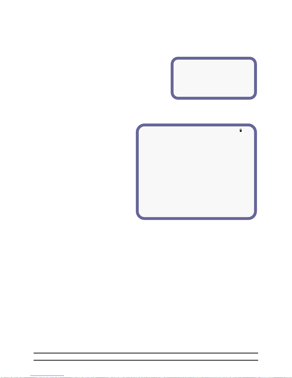
**Password Setup**
Enter a new password for this
controller and press ENTER:
New Password: 0000
**DIAGNOSTICS**
For Qualified Technician Use Only:
(1)Power Ventilation Auxilary SWX:
(2)Ignore Inlet #1 Auxiliary SWX = Yes
(3)Ignore Inlet #2 Auxiliary Swx = Yes
(4)Natural Ventilation Auxiliary SWX:
(5)Ignore Unit #1 Auxiliary SWX = Yes
(6)Ignore Unit #2 Auxiliary Swx = Yes
(7)Feed Level Sensor:
(8)Maximum Range = 26.00 ft
(9)Dead Zone = 1.50 ft
(10)GPAD12 = 115 GPAD13 = 105
GPAD14 = 98 GPAD15 = 90
(11)Soft Resets = 0
(12)Voltage Resets = 0
(13)Hard Resets = 0
(2) Program Name – The program name can be changed to include a special title, letters, numbers, and
characters up to 8 digits in length.
(3) Copy to Program – Enter the COPY TO program number (0, 1, or 2).
(4) Enter to Proceed – When “Enter to Proceed” is selected and the ENTER button is pressed, the Copy to
Program number programming contents is replaced with the programming contents of the Seasonal
Program number.
NOTE: This action is not reversible.
(5) Change Password – Select “Change Password” for
changing the existing password for the Controller. The
four digits will allow a numeric password from 0001 to
9999. Changing the Password to 0000 disables the
locks until the password is changed to a number
between 0001 and 9999.
NOTE: Record the password in a convenient retrievable location.
7.14 Diagnostics
The Diagnostics screen is for qualified
technician use only and can only be
changed by using the service code.
Contact the local dealer for assistance.
(1) Power Ventilation Auxiliary SWX -
Setting these options to Yes will
ignore the indication from the curtain
switch. This feature will totally
ignore the auxiliary switches on the
PT machines when answered yes.
Note: This must be answered 'No' and the
open auxiliary switch of the vent
machine must be connected in order
to use the feature of running the
tunnel curtain with the vents during
Power ventilation when the
pressure is to high and the vents are
completely open.
(2) Ignore Inlet #1 Auxiliary Switch - Yes or No
(3) Ignore Inlet #2 Auxiliary Switch - Yes or No
(4) Natural Ventilation Auxiliary SWX - Setting these options to Yes will ignore the indication from the
curtain switch. This feature will totally ignore the auxiliary switches on the PT machines when
answered "Yes".
Note: The auxiliary switches must be connected and this answered to no in order for the control to enter
into natural ventilation.
(5) Ignore Unit #1 Auxiliary Switch - Yes or No
(6) Ignore Unit #2 Auxiliary Switch - Yes or No
(7) Feed Level Sensor – Settings for setting the maximum range and calibration of the feed level sensor.
(8) Maximum Range - Total sensing range of the sensor.
Part No. 4801-5307 Rev 2-15 Evolution 3000 and 3001 41 of 70
(9) Dead Zone - Distance from the top of the feed bin to the bottom of the sensor.
Page 42
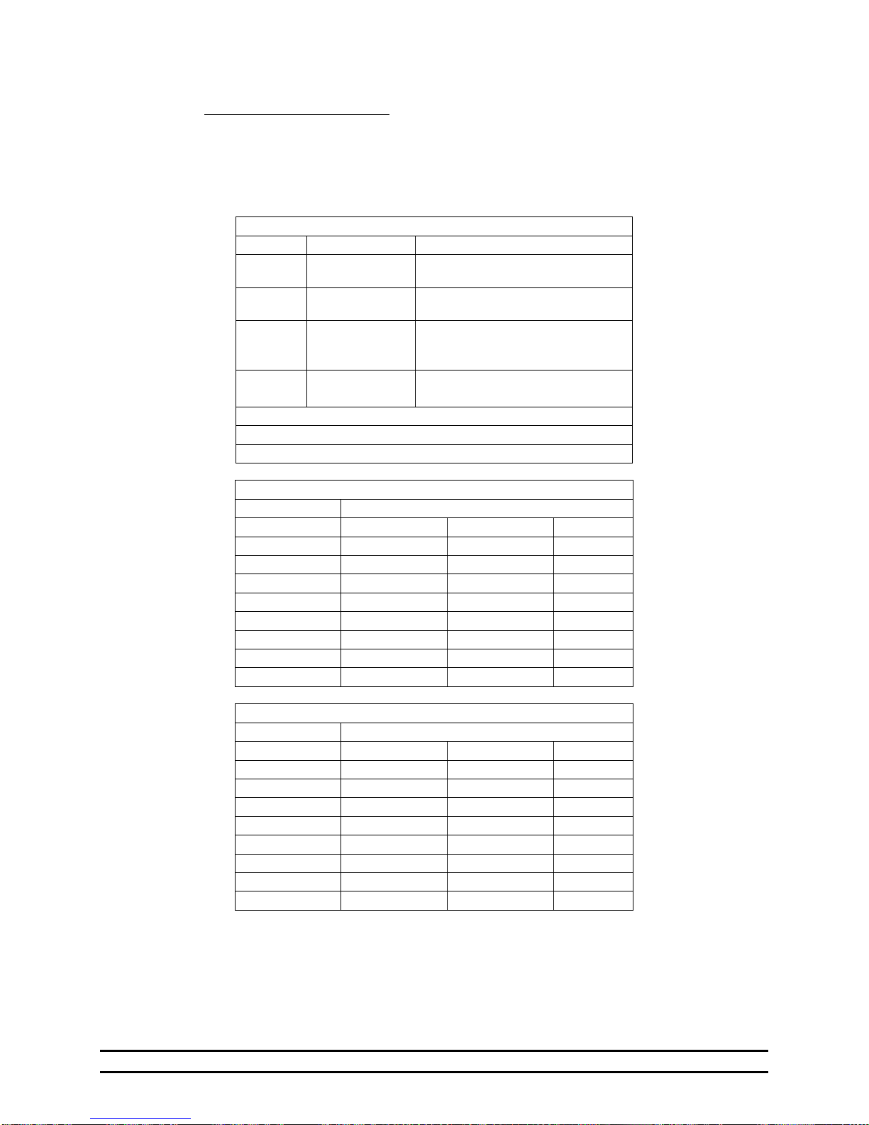
GPAD12 & GPAD13 -- Feed Level Sensor Inputs
Range
Status
Cause
0-24
Bin is full
Feed is on or above proximity
rod.
25-57
Loss of Echo
Bin may be empty or a sensor
error
58-239
Sensing Feed
Value should be based on level
of feed with 58 being
approximately full.
240-255
Error
Could represent empty but
probably a defective sensor.
GPAD12 = Bin 1
GPAD13 = Bin 2
GPAD14 -- Current Sensors for Auger 1, Auger 2, Belt 1
Motor Status
Range
Auger 1
Auger 2
Belt 1
0-115
On
On
On
116-124
Off
On
On
125-136
On
Off
On
137-151
Off
Off
On
152-169
On
On
Off
170-194
Off
On
Off
195-224
On
Off
Off
225-255
Off
Off
Off
GPAD15 -- Current Sensors for Belt 2, Belt 3, Belt 4
Motor Status
Range
Auger 1
Auger 2
Belt 1
0-115
On
On
On
116-124
Off
On
On
125-136
On
Off
On
137-151
Off
Off
On
152-169
On
On
Off
170-194
Off
On
Off
195-224
On
Off
Off
225-255
Off
Off
Off
(10) GPAD12 thru GPAD15 – For HHI Service Technician Use ONLY.
General Purpose A/D Readings:
As shown on the Diagnostics screen in Section 7.14, there is a section with four displays labeled
GPAD12, GPAD13, GPAD14, and GPAD15. These values represent the data being received from
the I/O Expansion Board, if equipped. These values will be used to troubleshoot your controller
by a qualified service technician in the case that a problem occurs with your I/O Expansion board.
The following tables give you an idea of the range of values and what they represent.
(11) Soft Resets - For HHI Use Only. Indicates that the control is sensing environmental problems which
can cause controller malfunctions.
(12) Voltage Resets - For HHI Use Only.
(13) Hard Resets - For HHI Use Only.
Part No. 4801-5307 Rev 2-15 Evolution 3000 and 3001 42 of 70
Page 43
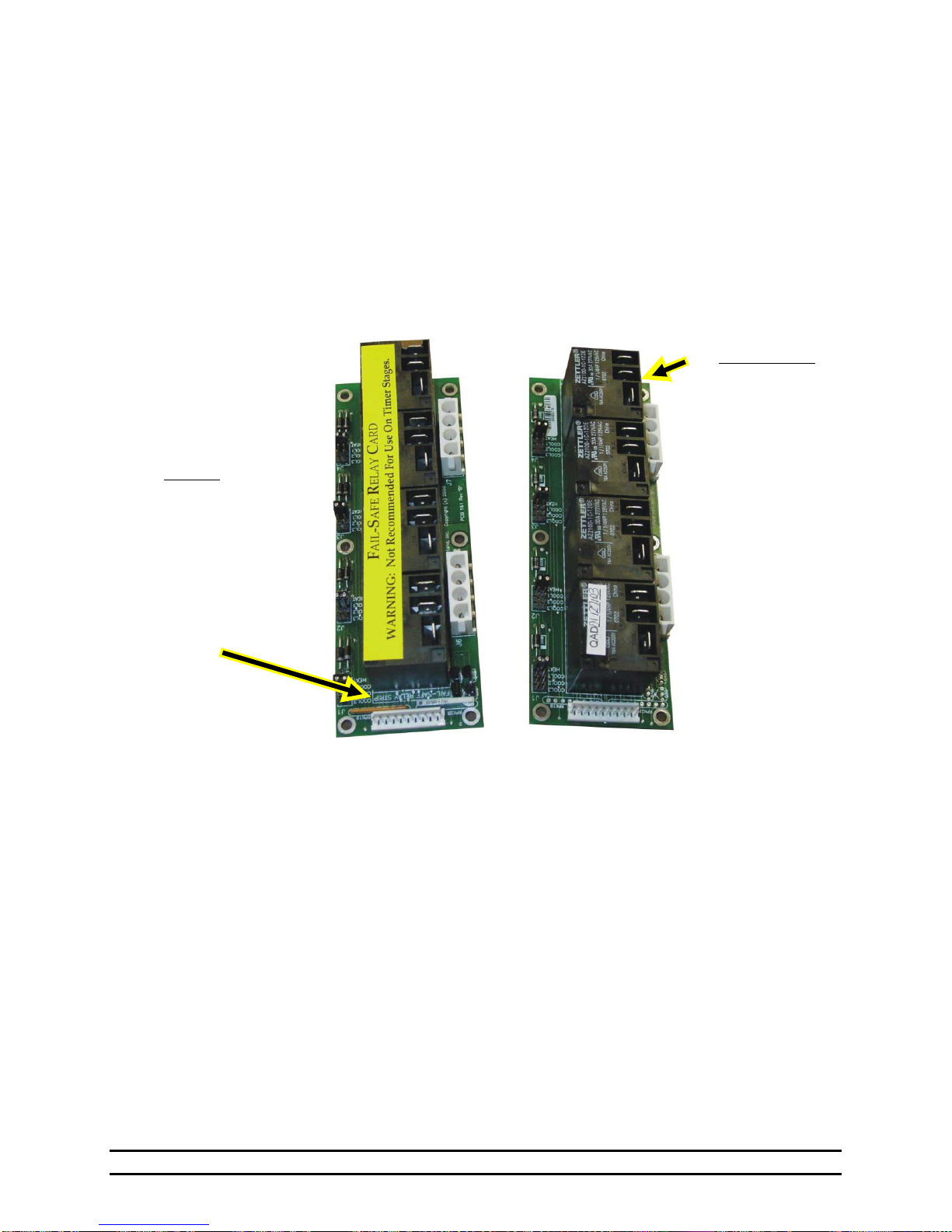
NOTE:
Older versions of the
Fail-Safe Relay Cards
will not have the
Yellow Warning
Label.
Look for the “FAILSAFE RELAY
STRIP” text visible
on this end of the
Fail-Safe Relay Card
circuit board.
NOTE:
The Normally Open
Relay Card will have
the “N.O. RELAY
STRIP” text visible
on this end of the
Relay Card circuit
board.
8. Fail-Safe Relay Operation
There are two types of Relay strips used in the Evolution. The Normally Open (NO) strip requires a signal
from the controller board in order to energize a stage of ventilation. Should power be removed from the
EV-3000 or 3001, the Normally Open Relay strips would not be able to energize a ventilator. On the other
hand, the Fail-Safe relay strip would close each of the relays in the strip resulting in energizing the
ventilators in case of a controller power failure. Each of the relay strips contains four relays for controlling
four stages. In the EV-3000 or 3001 there are a total of four relay strips; Three will be N.O. and one will
be a Fail-Safe. The operator must insure that the Fail-Safe relay strip is connected only to stages that should
be turned on in case of a controller failure. See the Section 9.9 for a physical description of the relay strips.
It is not recommended to place heating equipment on Fail-Safe stages.
WARNING: The Fail-Safe Relay Card Is Not Recommended For Use On Timer Stages.
Fail-Safe Relay Card Normally Open Relay Card
Part No. 4801-5307 Rev 2-15 Evolution 3000 and 3001 43 of 70
Page 44
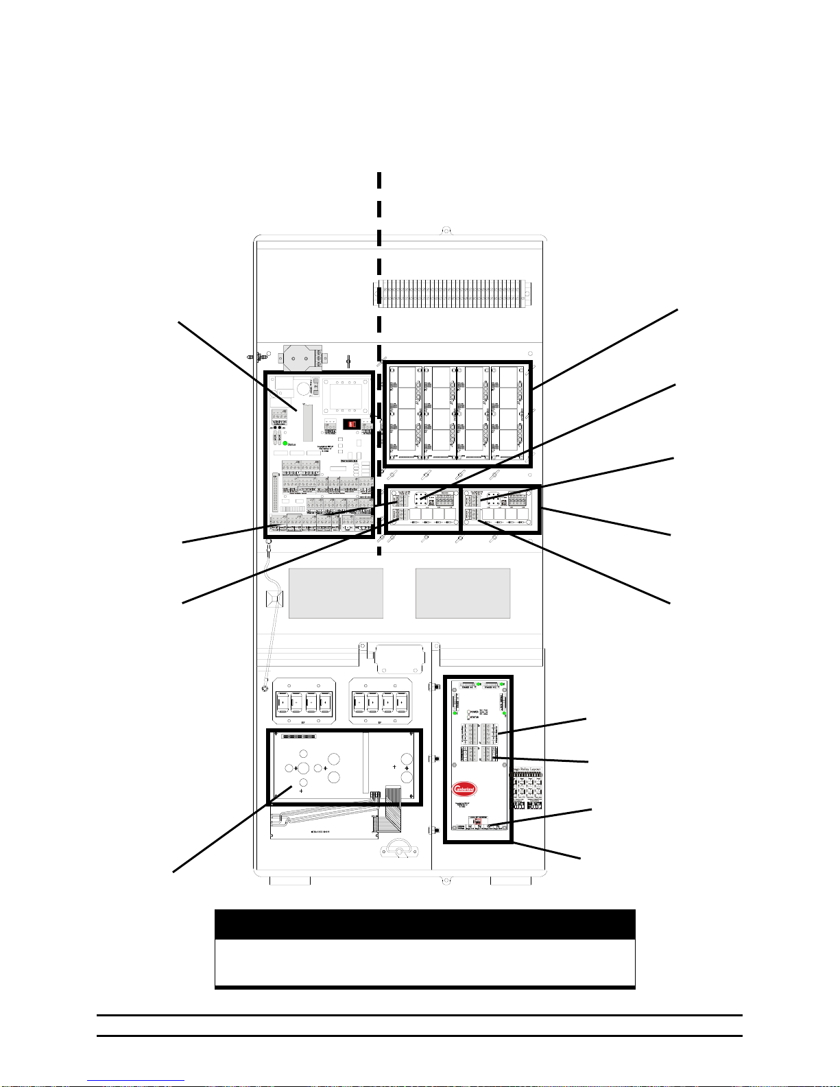
WARNING!
Keep All Low Voltage Wires Such As Sensors, Network, &
Backup, Curtain Aux Switches Separate From AC Wires!
View of Enclosure
Rear View of Front Panel
PCB 169
PCB 167
Power
Ventilation
PCB 167
Natural
Ventilation
Backup
Connection
Local Network
Connection
Stage Relays &
Stage
Connections
Address
Switches
U2 Natural
or Tunnel2
U1 Natural
Power Trak
or Attic
U2 Tunnel
Inlet Power
Trak
U1 Vent
Power Trak
PCB 170
PCB 168
LOW
VOLTAGE
WIRES
HIGH
VOLTAGE
WIRES
9. Wiring Diagrams
9.1 Connections of Evolution 3000 & 3001 Enclosure
Part No. 4801-5307 Rev 2-15 Evolution 3000 and 3001 44 of 70
Page 45
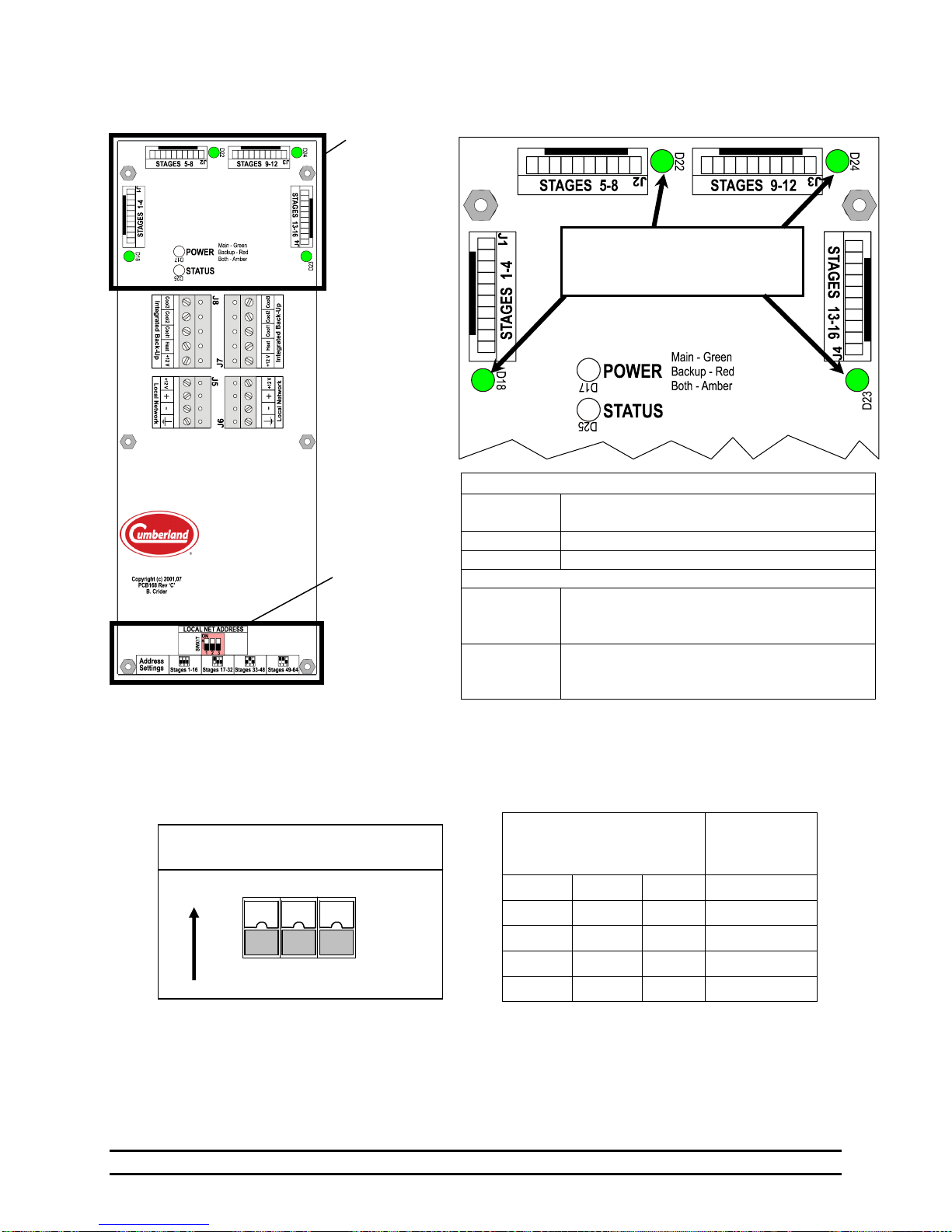
LOCAL NET ADDRESS
SWX 1
ON
1 2 3
Inset A
Inset A
PCB 168
Inset B: Light Emitting Diode (LED) Indicators
Relay POWER Status LED
ORANGE
Backup Power Supply & Main Controller
Power Supply Both Connected.
RED
Main Power Supply Lost
GREEN
Backup Power Supply Lost
STATUS LED
GREEN with
quick RED
flashes
If this LED is flashing Red, this board is
communicating with the PCB170 Board.
A slow
AMBER
flash
If this LED has a slow Amber flash, then a
problem exists with the local network
communication between PCB168 and PCB170.
LOCAL NET ADDRESS
Local addresses are assigned by setting a series of three DIP switches on the PCB 168 circuit board. There are
three switches that can be set as shown in the above table. For example, if all three DIP switches are set to
"ON", the Stages are 1 through 16.
DIP Switch Settings
Stage
Address
Assignment
No. 1
No. 2
No. 3
ON
ON
ON
1 -16
OFF
ON
ON
17-32
ON
OFF
ON
33-48
OFF
OFF
ON
49-64
When the Green Stage LED’s are
ON, PCB168 is sending power to
the Specific Stage Relay Boards.
Inset B
9.2 Setting Address Switches & LEDs on PCB 168 Stage Board
Part No. 4801-5307 Rev 2-15 Evolution 3000 and 3001 45 of 70
Page 46
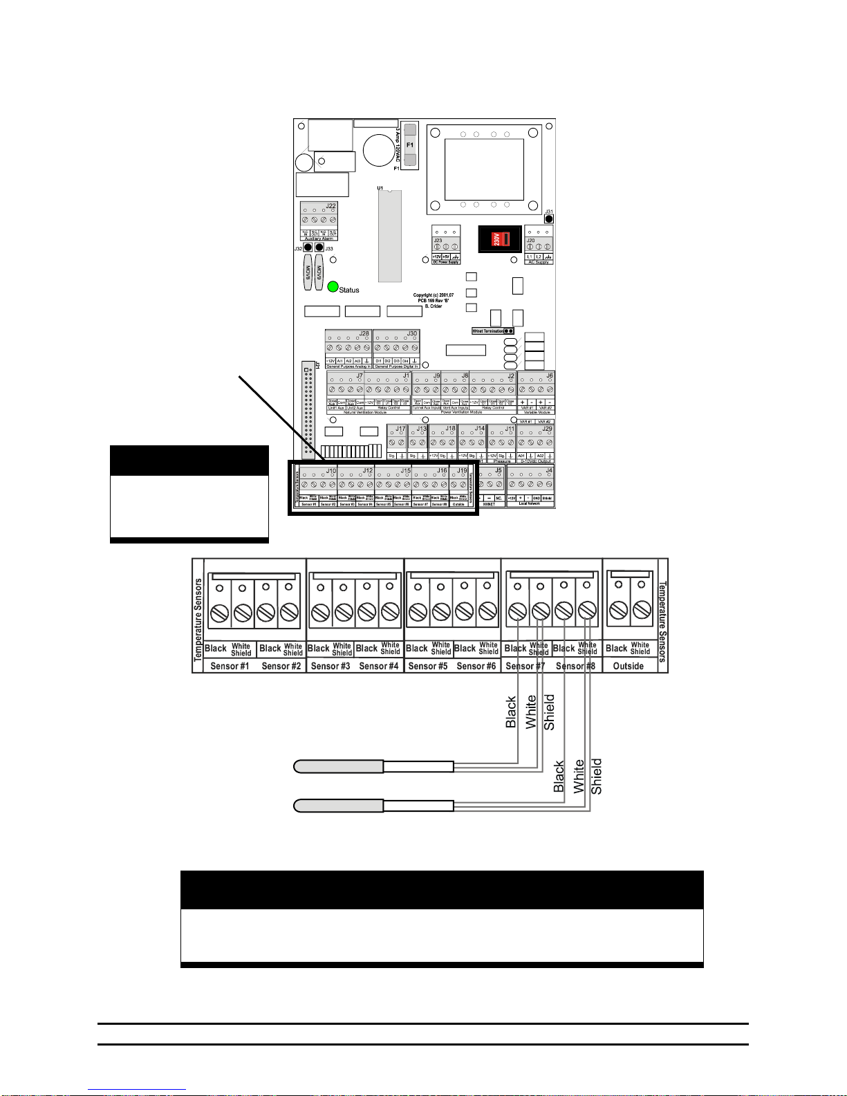
Warning!
Tape Shields To Prevent Bare Wires From Touching!
PCB 169
WARNING!
LOW VOLTAGE!
Keep Separate From
High Voltage Wires!
Inset A
NOTE: Other sensors are
connected similarly.
Inset A
9.3 Connecting Temperature Sensor to Evolution 3000 & 3001
Part No. 4801-5307 Rev 2-15 Evolution 3000 and 3001 46 of 70
Page 47
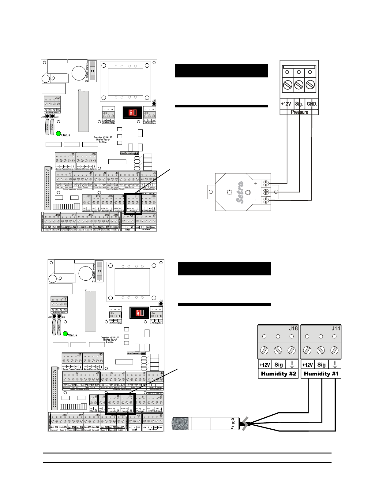
Inset A
Inset A
R
e
d
W
h
t
B
l
k
C
O
M
O
U
T
E
X
C
Pressure Sensor
WARNING!
LOW VOLTAGE!
Keep Separate From
High Voltage Wires!
Inset A
Inset A
Humidity Sensor
WARNING!
LOW VOLTAGE!
Keep Separate From
High Voltage Wires!
PCB 169
PCB 169
Black
Brown
Blue
Cooler
House
9.4 Connecting Static Pressure Sensor to Evolution 3000 & 3001
9.5 Connecting Humidity Sensor to Evolution 3000 & 3001
Part No. 4801-5307 Rev 2-15 Evolution 3000 and 3001 47 of 70
Page 48
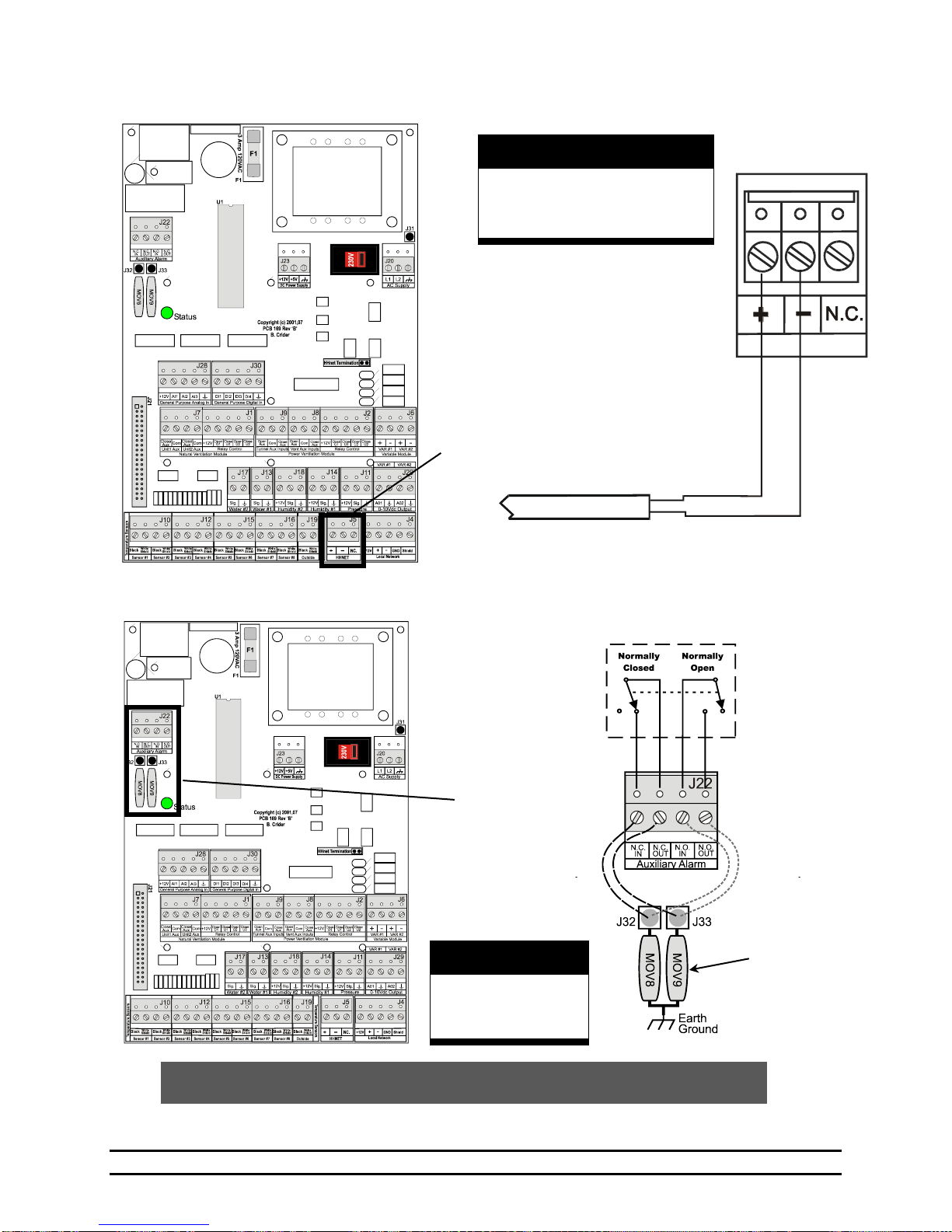
WARNING!
LOW VOLTAGE!
Keep Separate From
High Voltage Wires!
Inset A
PCB 169
Inset A
Twisted Pair
Cable
WARNING!
LOW VOLTAGE!
Keep Separate From
High Voltage Wires!
Inset A
NOTE: The internal wiring shows the condition of the relay during normal conditions
(no alarm present). During an alarm condition, the contact positions will be reversed.
N.O.
for Parallel Alarm
N.C.
for Series Alarm
Internal Circuit
Board Auxiliary
Alarm Relay
PCB 169
Inset A
On-Board Surge
Arrestors for
use with either
N.O. or N.C.
side.
9.6 Connecting PC Network to Evolution 3000 & 3001
9.7 Connecting Alarm Device to Evolution 3000 & 3001
Part No. 4801-5307 Rev 2-15 Evolution 3000 and 3001 48 of 70
Page 49
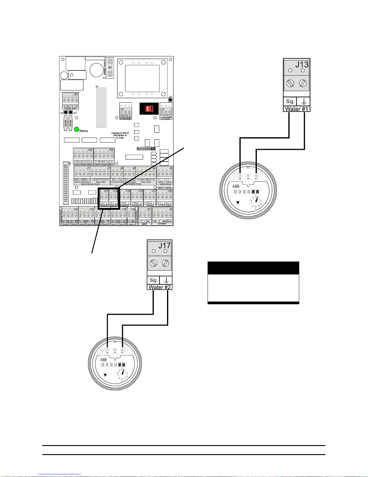
Inset A
Water
Meter #1
WARNING!
LOW VOLTAGE!
Keep Separate From
High Voltage Wires!
Inset B
Water
Meter #2
Inset B
Inset A
PCB 169
9.8 Connecting Water Meter to Evolution 3000 & 3001
Part No. 4801-5307 Rev 2-15 Evolution 3000 and 3001 49 of 70
Page 50
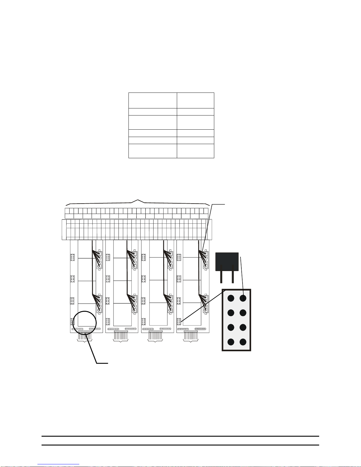
Stage
Operation
Jumper
Cool Negative
COOL 1
Cool Negative
Tunnel Fan
COOL 2
Cool Tunnel Fan
COOL 3
Heat Stage
HEAT
Stage NOT in
Back-up
No Jumper
installed
Fail-safe relays
(NOTE: 'Fail-safe'
written on relay board)
Stage harness
connector cables
to terminal block
Stage
Jumpers
HEAT
COOL 1
COOL 2
COOL 3
In
Out
Stage
In
Out
Stage
In
Out
Stage
In
Out
Stage
In
Out
Stage
In
Out
Stage
In
Out
Stage
In
Out
Stage
In
Out
Stage
In
Out
Stage
In
Out
Stage
In
Out
Stage
In
Out
Stage
In
Out
Stage
In
Out
Stage
In
Out
Stage
To
PCB 168
To
PCB 168
To
PCB 168
To
PCB 168
Stage Connections
J2
J1
J3
J4
J2
J1
J3
J4
J2
J1
J3
J4
J2
J1
J3
J4
Stage 1
Relay
Stage 2
Relay
Stage 3
Relay
Stage 4
Relay
Stage 5
Relay
Stage 6
Relay
Stage 7
Relay
Stage 8
Relay
Stage 9
Relay
Stage 10
Relay
Stage 11
Relay
Stage 12
Relay
Stage 13
Relay
Stage 14
Relay
Stage 15
Relay
Stage 16
Relay
Fail-safe
WARNING:
Do Not Use Timer Fans On Fail-Safe.
9.9 Connecting Stage Jumpers of Evolution 3000 & 3001
Pictured at below is a stage relay board consisting of four stage relays and the associated stage jumper for
each relay. The stage jumpers are labeled COOL 1, COOL 2, COOL 3, and HEAT. Location of the jumper
places the stage in one of these four modes, or if the jumper is NOT inserted, the stage is NOT placed on
Back-up. The jumpers should be placed based on the operation of stage equipment and should be the same
as assigned in the Master Controller.
Jumpers are placed according to the following table:
Part No. 4801-5307 Rev 2-15 Evolution 3000 and 3001 50 of 70
Page 51
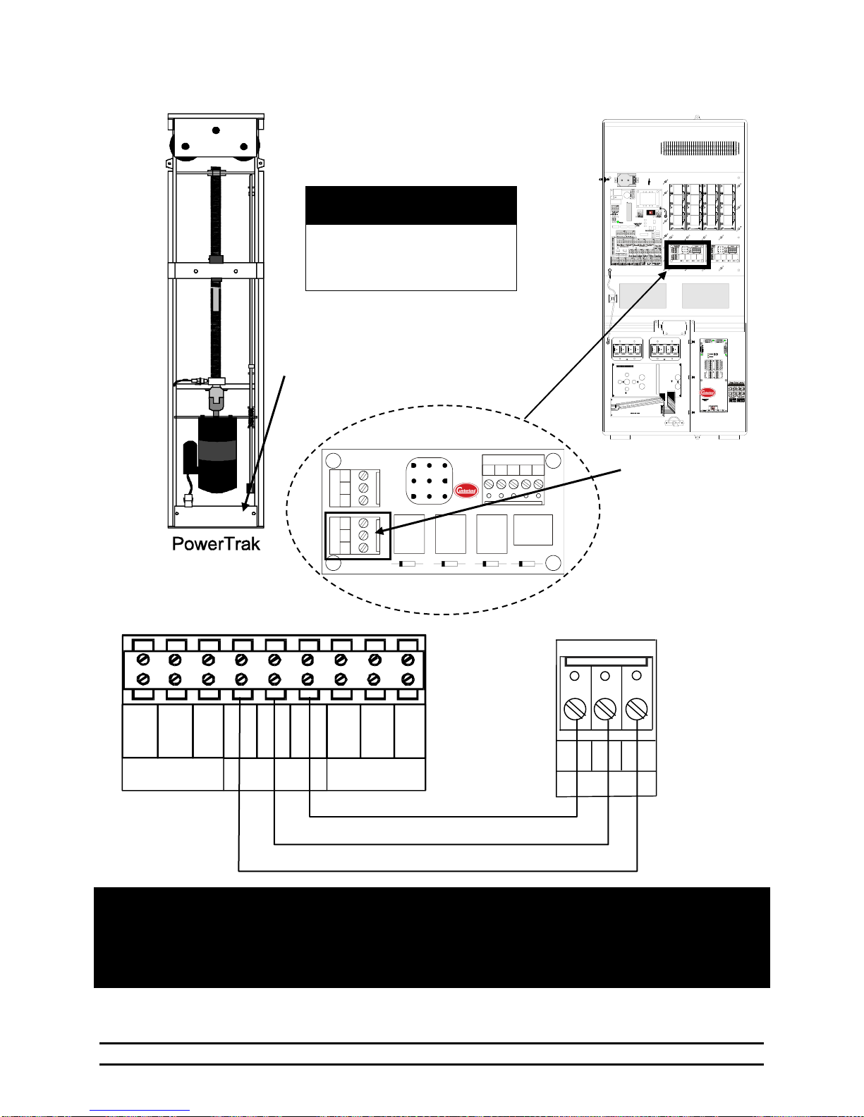
PowerTrak
AUX
SWITCH
CONTROLLER
AC IN
HOT
NEUT.
LOWER GND.
HOT OUT CLOSE
IN OPEN IN
COM UPPER
NOTE: If curtain is setup to pull curtain up to open, then reverse wires connected to "OPEN" and "CLOSE"
terminals.
NOTE: Only 1 Power Trak can be connected to each Power Trak outlet. If Additional Power Traks are needed,
Then use of relay boxes is necessary to separate the load.
NOTE: All PowerTrak units will connect the same.
Inset A
Unit #2 Vents
Unit #2 Vents
COM
Close
Open
Inset B
Inset B
J
1
J
2
Hired - Hand
B. Crider
D
1
D
2
D
3
D
4
Copyright (c) 2000
PCB 167 Rev ‘0’
C
O
M
O
pen
C
lose
U
nit #1 (Vents)
C
O
M
O
pen
C
lose
U
nit #2 (Tunnel)
+12V
Open
U1
Relay Control
CloseU1OpenU2Close
U2
HIRED-HAND
RLY
1
RLY
2
RLY
3
RLY
4
Inset A
PCB – 167 Power Ventilation
WARNING!
Keep High Voltage (Or AC)
Separate From Low Voltage
Wires!
Evolution 3000 / 3001
9.10 Connecting the PowerTrak to the Evolution 3000 & 3001
Part No. 4801-5307 Rev 2-15 Evolution 3000 and 3001 51 of 70
Page 52
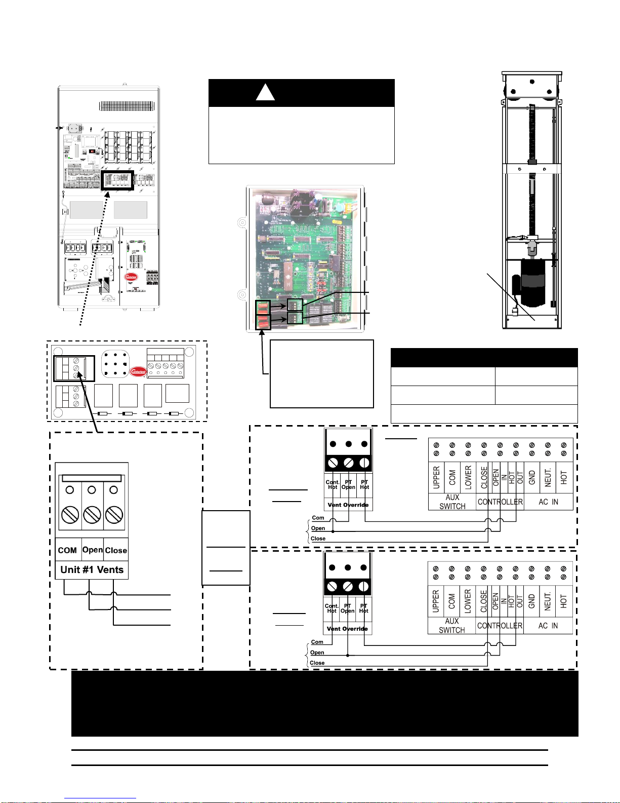
WARNING!
Keep High Voltage (Or AC) Separate
From Low Voltage Wires!
Do not perform modifications or wiring
with voltage applied!
!
Inset B
S-3 Vent
Override
for
Fail-Safe
Action
INLET
MODE
Vent Override
Cool 1
Tunnel Override
Cool 3
Vents & Tunnel Will Wire The Same
PowerTrak
Inset C
Inset B
S-3 Vent
Override
for
Normal
Action
NOTE:
Refer to the
S-3 Manual
4801-2997 for
additional P5
& P6
S-3 Setting
Instructions
PowerTrak
Inset C
PowerTrak
Inset C
Evolution 3000 / 3001
Inset A
PCB – 167 Power Ventilation
NOTE: If curtain is setup to pull curtain up to open, then reverse wires connected to "OPEN" and "CLOSE" terminals.
NOTE: Only 1 Power Trak can be connected to each Power Trak outlet. If Additional Power Traks are needed,
Then use of relay boxes is necessary to separate the load.
NOTE: All PowerTrak units will connect the same.
To
EV-3000/3001
PCB 167
To
EV-3000/3001
PCB 167
Unit #1 Vents
Open
Close
Com
To
EV
S-3
Wire for
Either
Fail-Safe
OR
Normal
Action
NOTE:
If connecting the Back-Up
to a relay box instead of
PowerTrak, Cut and
discard the specific two or
four components shown as
needed.
Secondary Sensing System
Tunnel Override
Inset B
Vent Override
}
EV-3000/3001
PCB 167
J 1 J
2
-
B . C r i d e r D 1 D 2 D 3 D 4 C o p y r i g h t ( c ) 2 0 0 0 P C B 1 6 7 R e v ‘ 0 ’ C O M O p e n C l o s e U n i
t #
1 ( V e n t s ) C O M O p e n C l o s e U n i t #
2 ( T u n n e l ) +12V
Open
U1
Relay Control
Close
U1
Open
U2
Close
U2 R L Y 1 R L
Y 2 R L
Y 3 R L
Y 4
9.11 Connecting the PowerTrak and S-3 Back-Up to the Evolution 3000 & 3001
Part No. 4801-5307 Rev 2-15 Evolution 3000 and 3001 52 of 70
Page 53
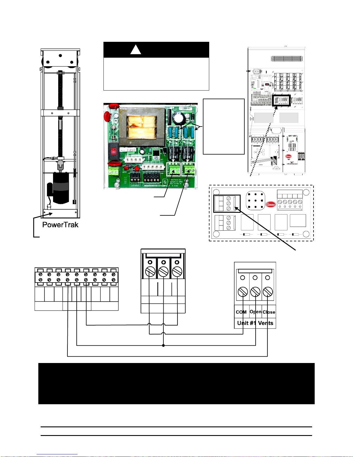
PowerTrak
AUX
SWITCH
CONTROLLER
AC IN
HOT
NEUT.
LOWER GND.
HOT OUT CLOSE
IN OPEN IN
COM UPPER
NOTE: If curtain is setup to pull curtain up to open, then reverse wires connected to "OPEN" and "CLOSE"
terminals.
NOTE: Only 1 Power Trak can be connected to each Power Trak outlet. If Additional Power Traks are needed,
Then use of relay boxes is necessary to separate the load.
NOTE: All PowerTrak units will connect the same.
Inset C
Unit #2 Vents
Inset A
WARNING!
Keep High Voltage (Or AC) Separate
From Low Voltage Wires!
Do not perform modifications or wiring
with voltage applied!
Inset B
Vent Override
PT Hot
Open
Close
Inset A
PowerTrak
Cont
Hot PHot
P
Ope
Vent Override
Com
!
Evolution Back-Up Circuit Board
Inset B
Vent Override
NOTE:
If connecting the
Back-Up to a
relay box instead
of PowerTrak,
Cut and discard
the specific two
or four
components
shown as needed.
Tunnel Override
Evolution 3000 / 3001
Inset C
PCB – 167 Power Ventilation
J
1
J
2
Hired - Hand
B. Crider
D
1
D
2
D
3
D
4
Copyright (c) 2000
PCB 167 Rev ‘0’
C
O
M
O
pen
C
lose
U
nit #1 (Vents)
C
O
M
O
pen
C
lose
U
nit #2 (Tunnel)
+12V
Open
U1
Relay Control
CloseU1OpenU2Close
U2
HIRED-HAND
RLY
1
RLY
2
RLY
3
RLY
4
9.12 Connecting the PowerTrak and EV Back-Up to the Evolution 3000 & 3001
Part No. 4801-5307 Rev 2-15 Evolution 3000 and 3001 53 of 70
Page 54
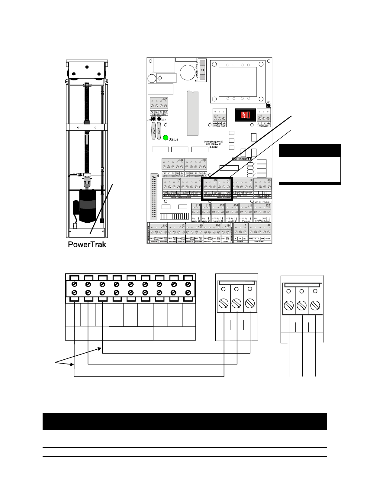
PowerTrak
AUX
SWITCH
CONTROLLER
AC IN
HOT
NEUT.
LOWER
GND.
HOT
OUT
CLOSE
IN
OPEN
IN
COM
UPPER
Inset A
Tunnel Aux. Input
Open
AUX
Close
AUX
Com
Inset A
Tunnel Auxiliary
Input
See Note
below
Inset C
Inset C
Vent Aux. Input
Open
AUX
Close
AUX
Com
Inset B
Vent Auxiliary
Input
NOTE: Vent auxiliary
connects the same as
tunnel auxiliary.
Inset B
WARNING!
LOW VOLTAGE!
Keep Separate From
High Voltage Wires!
PCB 169
9.13 Connecting the Power Trak Power Auxiliary Switches to Evolution 3000 &
3001
NOTE: If curtain is setup to pull curtain up to open, then reverse wires connected to
“Upper” and “Lower” terminals.
Part No. 4801-5307 Rev 2-15 Evolution 3000 and 3001 54 of 70
Page 55
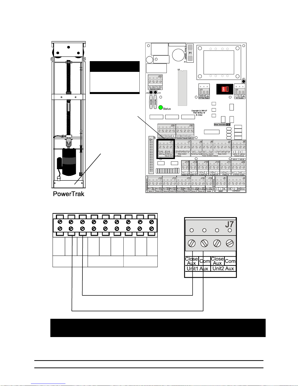
PowerTrak
AUX
SWITCH
CONTROLLER
AC IN
HOT
NEUT.
LOWER
GND.
HOT
OUT
CLOSE
IN
OPEN
IN
COM
UPPER
NOTE: If curtain is setup to pull curtain up to open, then reverse wires
connected to 'Upper' and 'Lower' terminals.
Inset A
Inset B
Inset A
Natural Auxiliary
Input
WARNING!
LOW VOLTAGE!
Keep Separate From
High Voltage Wires!
PCB 169
9.14 Connecting PowerTrak Natural Auxiliary Switches to Evolution 3000 & 3001
Part No. 4801-5307 Rev 2-15 Evolution 3000 and 3001 55 of 70
Page 56
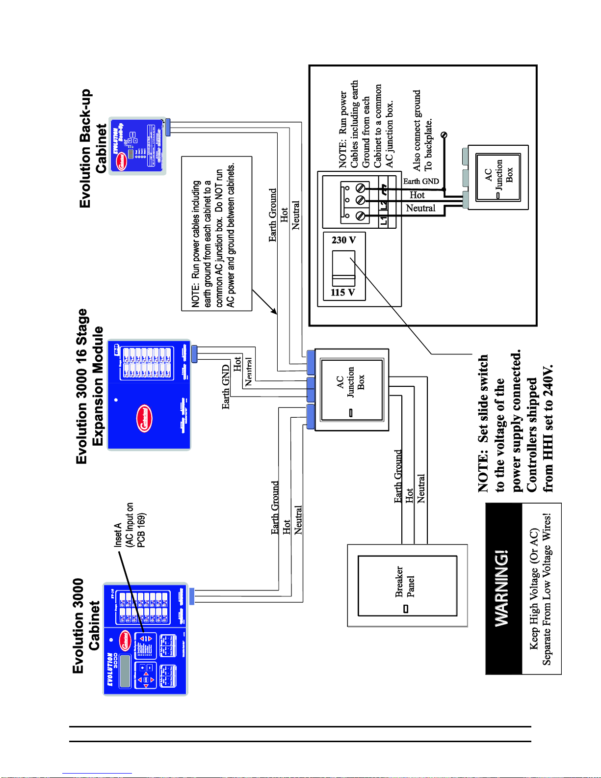
9.15 Power Supply Connection
Part No. 4801-5307 Rev 2-15 Evolution 3000 and 3001 56 of 70
Page 57
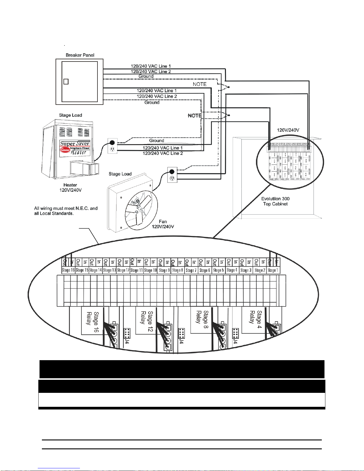
NOTE: Example above shows how to wire stages to heating & cooling equipment. Stage numbers are
shown on label affixed to inside top of controller box.
Connecting Power from Breaker to a Heat Stage
And a Cool Stage in the Evolution 3000
Terminal block for
stage connections
Evolution 3000 & 3001
Top Cabinet
WARNING!
Keep High Voltage (Or AC) Separate From Low Voltage Wires!
9.16 Evolution 3000 & 3001 Power Connection
Part No. 4801-5307 Rev 2-15 Evolution 3000 and 3001 57 of 70
Page 58
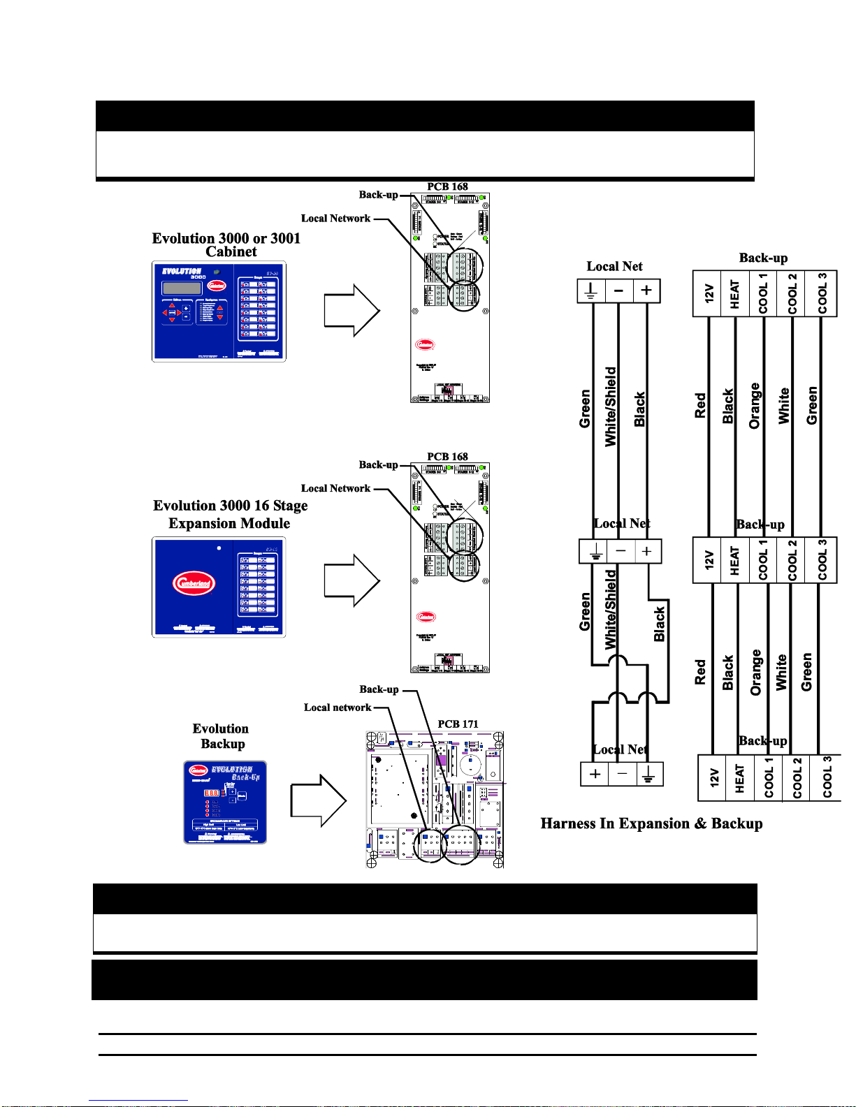
NOTE: Harness to connect Local Network and Back-up together are connected & included
in the Back-up and 16 Stage Expansion units.
Warning!
Tape Shield To Prevent Damage!
WARNING!
LOW VOLTAGE!
Keep Low Voltage Wires Separate Frm High Voltage Wires
9.17 Connecting Local Network & Backup to the Evolution 3000 & 3001
Part No. 4801-5307 Rev 2-15 Evolution 3000 and 3001 58 of 70
Page 59
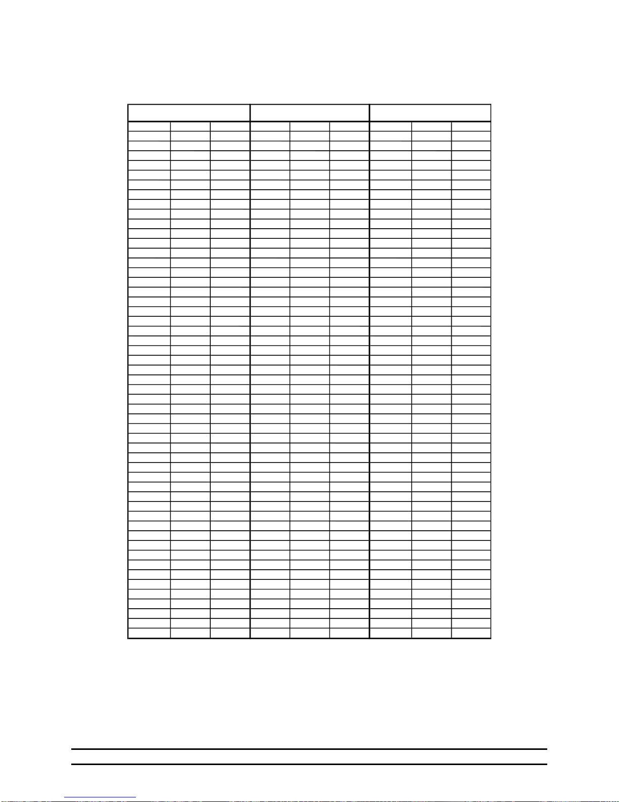
Resistencia
Temp
Temp
Resistencia
Temp
Temp
Resistencia
Temp
Temp
Kohms
(F)
(C)
Kohms
(F)
(C)
Kohms
(F)
(C)
32.654
32015.714
59158.59
83.3
28.5
32.158
32.5
0.3
15.568
59.4
15.2
8.517
83.7
28.7
31.671
33.1
0.6
15.353
59.9
15.5
8.408
84
28.9
31.191
33.6
0.9
15.211
60.3
15.7
8.336
84.6
29.2
30.72
34.2
1.2
15.001
60.8168.23
85.1
29.5
30.257
34.7
1.5
14.863
61.2
16.2
8.125
85.6
29.8
29.802
35.2
1.8
14.658
61.7
16.5
8.056
86
30
29.355
35.8
2.1
14.457
62.2
16.8
7.954
86.5
30.3
28.915
36.3
2.4
14.325
62.6177.853
87.1
30.6
28.482
36.9
2.7
14.128
63.1
17.3
7.787
87.4
30.8
28.057
37.4313.999
63.5
17.5
7.689
88
31.1
27.777
37.8
3.2
13.808
64
17.8
7.592
88.5
31.4
27.363
38.3
3.5
13.682
64.4187.496
89.1
31.7
26.957
38.8
3.8
13.496
64.9
18.3
7.433
89.4
31.9
26.557
39.4
4.1
13.373
65.3
18.5
7.349032.2
26.164
39.9
4.4
13.192
65.8
18.8
7.248
90.5
32.5
25.777
40.5
4.7
13.073
66.2197.157
91
32.8
25.523
40.8
4.9
12.896
66.7
19.3
7.098
91.4
33
25.147
41.4
5.2
12.779
67.1
19.5
7.009
91.9
33.3
24.777
41.9
5.5
12.607
67.6
19.8
6.922
92.5
33.6
24.413
42.4
5.8
12.493
68206.836
93
33.9
24.055
43
6.1
12.325
68.5
20.3
6.779
93.4
34.1
23.82
43.3
6.3
12.215
68.9
20.5
6.695
93.9
34.4
23.472
43.9
6.6
12.051
69.4
20.8
6.612
94.5
34.7
23.13
44.4
6.9
11.943
69.8216.531
95
35
22.793
45
7.2
11.783
70.3
21.3
6.45
95.5
35.3
22.572
45.3
7.4
11.678
70.7
21.5
6.371
96.1
35.6
22.244
45.9
7.7
11.522
71.2
21.8
6.319
96.4
35.8
21.922
46.4811.42
71.6226.241
97
36.1
21.71
46.8
8.2
11.268
72.1
22.3
6.165
97.5
36.4
21.397
47.3
8.5
11.168
72.5
22.5
6.089
98.1
36.7
21.088
47.8
8.8
11.02
73
22.8
6.015
98.6
37
20.886
48.2910.874
73.6
23.1
5.941
99.1
37.3
20.586
48.7
9.3
10.778
73.9
23.3
5.869
99.7
37.6
20.29
49.3
9.6
10.636
74.5
23.6
5.798
100.2
37.9
20.096
49.6
9.8
10.542
74.8
23.8
5.728
100.8
38.2
19.809
50.2
10.1
10.404
75.4
24.1
5.658
101.3
38.5
19.526
50.7
10.4
10.312
75.7
24.3
5.59
101.8
38.8
19.34
51.1
10.6
10.177
76.3
24.6
5.522
102.4
39.1
19.065
51.6
10.9
10.088
76.6
24.8
5.456
102.9
39.4
18.884
52
11.1
9.956
77.2
25.1
5.39
103.4
39.7
18.616
52.5
11.4
9.869
77.5
25.3
5.326
104
40
18.352
53.1
11.7
9.741
78.1
25.6
5.262
104.5
40.3
18.179
53.4
11.9
9.614
78.6
25.9
5.199
105.1
40.6
17.503
54.9
12.7
9.537926.1
5.137
105.6
40.9
17.339
55.2
12.9
9.407
79.5
26.4
5.076
106.2
41.2
17.095
55.8
13.2
9.325
79.9
26.6
4.995
106.9
41.6
16.856
56.3
13.5
9.205
80.4
26.9
4.936
107.4
41.9
16.698
56.7
13.7
9.086
81
27.2
4.877
108
42.2
16.465
57.2149.007
81.3
27.4
4.82
108.5
42.5
16.312
57.6
14.2
8.891
81.9
27.7
4.763
109
42.8
16.085
58.1
14.5
8.815
82.2
27.9
4.688
109.8
43.2
15.935
58.5
14.7
8.702
82.8
28.2
10. Temperature vs. Sensor Resistance Table
The following chart gives the resistance when measured between the white and black sensor wires at a given
temperature. To check a sensor, first know the temperature in the area, then use a multi-meter to check the
resistance.
Part No. 4801-5307 Rev 2-15 Evolution 3000 and 3001 59 of 70
Page 60

Main Controls
HHI Part
Number
Model
Description
6607-8039
EV-S3-16
Secondary Sensing System Control Expansion with 16 stages
6607-8013
EV Secondary Sensing System Plus
With Relay Card
6607-8014
EV Secondary Sensing System
6607-8015
EV-Back-up
6607-8016
EV-16-Expansion
6607-8020
EV-3000-R1-00
(For replacement of VM24 to connect to SCS)
6607-8021
EV-3000-16-00
(No curtain output)
6607-8022
EV-3000-16-01
(With Power Ventilation)
6607-8023
EV-3000-16-02
(With Natural Ventilation)
6607-8024
EV-3000-16-03
(With Power and Natural Ventilation)
6607-8025
EV-3001-16-00
(No curtain output)
6607-8026
EV-3001-16-01
(With Power Ventilation)
6607-8027
EV-3001-16-02
(With Natural Ventilation)
6607-8028
EV-3001-16-03
(With Power and Natural Ventilation)
6607-8201
EV-3000-16-S0 Spanish
(No curtain output)
6607-8202
EV-3000-16-S1 Spanish
(With Power Ventilation)
6607-8203
EV-3000-16-S2 Spanish
(With Natural Ventilation)
6607-8204
EV-3000-16-S3 Spanish
(With Power and Natural Ventilation)
6607-8205
EV-3001-16-S0 Spanish
(No curtain output)
6607-8206
EV-3001-16-S1 Spanish
(With Power Ventilation)
6607-8207
EV-3001-16-S2 Spanish
(With Natural Ventilation)
6607-8208
EV-3001-16-S3 Spanish
(With Power and Natural Ventilation)
11. Parts List
Part No. 4801-5307 Rev 2-15 Evolution 3000 and 3001 60 of 70
Page 61

Accessories
HHI PN
Description
6450-5101
KIT EV static pressure 4 stg
6450-5102
KIT EV natural vent 4 stg
6450-5103
KIT EV Humidity Sensor
6450-5104
KIT EV Vent Expansion
3025-0101
MTR Wtr 5/8x3/4 w/ 1g Reed SWX (Water Meter)
6407-6084
Temperature Sensor Junction Box Assembly
6407-6038
EV-S3 Stand Alone Relay Card
3591-2252
MODULE Static pres xmitr Setra
Variable/Dimmer Modules
6607-8031
EV-Variable 4KW/4HP(2 Outputs)
6607-8032
EV-Variable 8KW/8HP(4 Outputs)
6607-8033
EV-VAR Manual/Auto 4KW/HP(2 Outputs)
6607-8034
EV-VAR Manual/Auto 8KW/HP(4 Outputs)
Feed Management
6407-6035
EV I/O Expansion
6407-6036
Feed Bin Level Sensor
6407-6070
Current Sensor .35-100A (For use with belts, motors, or feed augers.)
Farm Manager Network
6626-0000
Software Kit FH Explorer (Wired)
6626-0100
Software Kit with 2-900SS (Wireless
Farm Manager Accessories
6407-5110
HHI Router / Repeater
6407-5111
900SS Wireless Repeater
6626-3500
Wireless Installation Kit
Palm
6626-3000
Software EV-Ware TO GO (Palm)
6450-5110
/Kit EV-Control Palm Connection
Part No. 4801-5307 Rev 2-15 Evolution 3000 and 3001 61 of 70
Page 62

Circuit Boards
6407-1511
PCB161 EV fail safe rly w QA
6407-1513
PCB161 EV relay w QA
6407-1516
PCB167 EV curtain rly w QA
6407-1518
PCB168 EV 16 Stg SWX w QA
6407-1520
PCB169 EV Master I/O w QA
6407-1522
PCB170 EV 3000 Interface w QA
6407-1523
PCB170 EV 3001 Interface w QA
6407-1592
PCB170 EV 3000 Spanish Interface w QA
6407-1593
PCB170 EV 3001 Spanish Interface w QA
6407-1526
PCB171 EV backup PS w QA
6407-1528
PCB184 EV 16 Stg PS w QA
6407-1536
PCB172 EV-Variable w/QA
6407-6011
EV-3000 Display Assy. (LCD Display only)
6407-6026
EV Back-up Door Assy.
6407-6050
EV-3001 Display Assy. (LCD Display only)
6407-1538
PCB174 Dimmer M/A w/QA
Chips
3701-6061
FLASH EV3000 (For PCB170)
3701-6065
FLASH EV3001 (For PCB170)
3701-6076
FLASH Spanish EV3000 (For PCB170)
3701-6077
FLASH Spanish EV3001 (For PCB170)
3701-6062
PIC EV3000 (For PCB170)
3540-0148
EEPROM 25C640 (For U10 and U11 of PCB170)
3701-6063
PIC EV300X I/O (For PCB169 rev A or 0, Use software Rev0.02 or earlier)
3701-6078
PIC EV300X B I/O
(For PCB169 rev B or later, use software Rev0.03 or later)
3701-6064
PIC EV-Backup (For PCB163)
Fuses
3010-2991
FUSE 3 AMP 5mmX20mm (For PCB169 and 171)
3010-2540
FUSE 20 A 1/4X1-1/4 (For PCB172-Variable Modules)
Terminal Blocks
3006-5076
CONN TBLK 2 pos EBY (Black)
3006-5077
CONN TBLK 3 pos EBY (Black)
3006-5078
CONN TBLK 4 pos EBY (Black)
3006-5079
CONN TBLK 5 pos EBY (Black)
3006-5082
CONN TBLK 3 pos Magnum (Green)
Part No. 4801-5307 Rev 2-15 Evolution 3000 and 3001 62 of 70
Page 63

Harnesses and Cables
1903-4008
HRNS Evo. 40pin I/O to Interface
1903-4009
HRNS Evo. 20pin Interface to Display
1903-5052
HRNS EV. Local Network 6ft.
1702-5190
WC&S 6' 18/5 Back-up connection
6407-6017
/EV.Inlet Machine SWX Assy.
Tools
0605-0107
TOOL PLCC Extraction Tool (For Removal of Chips)
Manuals
4801-5307
MANUAL EVOLUTION 3000/3001
4801-5332
MANUAL EVOLUTION 3000/3001 Spanish
4801-5308
MANUAL Evolution Ventilation. Add-on
4801-5309
MANUAL EVOLUTION BACK-UP
4801-5310
MANUAL EV-3000 Power Supply
4801-5315
MANUAL EV-Variable drives
4801-2997
MANUAL Secondary Sensing System
4801-3001
MANUAL Secondary Sensing System Expansion
4801-2998
MANUAL Feed Management
4801-2995
MANUAL 900SS Wireless
4801-2996
MANUAL HHI Repeater
4801-5152
EV High Temperature Monitor
Application Notes
4809-0011
Application Note – Inlet Operation (for Attic Inlets)
Replacement Parts
Hardware
1001-1462
#6 Nylon nut
1001-1463
#4 Nylon nut
1018-3001
SPACER Nylon .375L For #6 bolt (for PCB 170)
1018-3003
SPACER Nylon .625L For #6 bolt (for PCB 168)
1818-3005
SPACER Nylon .25L For #4 bolt (for Display)
Part No. 4801-5307 Rev 2-15 Evolution 3000 and 3001 63 of 70
Page 64
Cumberland, Inc.
Poultry House Layout and Specification
1. House Specification
Building Size
Name:
Vents
Stage
Equipment
1 2 3 4 5 6 7 8 9 10 11 12
13
14 15 16 17 18 19 20 21 22 23 24
25 26 27 28 29 30 31
32
Legend
Sensors
S Main
B Backup
A Alarm
Equipment
O Brooders
F Fans
H Heaters
T Tunnel
Machine
V Vent
Machine
* Indicates
distance from
end wall on
equipment
* Mark fans
with size and
number
Inlet Size
Cumberland. 1004 E. Illinois St. Assumption, IL 62510 Phone 1-217-226-4421 Fax 1-217-226-4420
Part No. 4801-5307 Rev 2-15 Evolution 3000 and 3001 64 of 70
Manual Part No. 4801-5307
Page 65
Cumberland, Inc.
Poultry House Layout and Specification
Stage
Sensors
On Point
Off Point
Mode
Timers
1.
2.
3.
4.
5.
6.
7.
8.
9.
10.
11.
12.
13.
14.
15.
16.
17.
18.
19.
20.
21.
22.
23.
24.
25.
26.
27.
28.
29.
30.
31.
32.
2. Stage Programming
Target _____
Modes: Heat, Cool Stir, Negative, Negative Tunnel, Tunnel, Feed, Lights
Timers: Minimum 1, Minimum 2, Variable, Cool
Part No. 4801-5307 Rev 2-15 Evolution 3000 and 3001 65 of 70
Page 66
Cumberland, Inc.
Poultry House Layout and Specification
Target
Growout Day
Day
Timer %
Stages
3. Temperature Curve
4. Static Pressure Settings
Vent Inlet Static Pressure _____
Pressure Ramping off of Outside Temperature
Pressure _____ at _____ High Temperature.
Pressure _____ at _____ Low Temperature.
Vent Delay _____ (seconds) Vent Anticipation _____ (seconds)
5. Minimum Vent
Timer Cycle _____ (minutes)
6. Tunnel Settings
Tunnel Sensors: _____
Tunnel On Temperature: _____ (Based off of Target Temperature from Section 2)
Tunnel OFF Temperature: _____ (Based off of Target Temperature from Section 2)
Tunnel Target Pressure: _____
Use Low Pressure Alarm in Tunnel: _____
Disable Tunnel until Growout day: _____
Cool Timer for Evaporative cooling
Timer Cycle _____ (minutes)
Max. Run % _____
Min. Run % _____
Part No. 4801-5307 Rev 2-15 Evolution 3000 and 3001 66 of 70
Page 67
Cumberland, Inc.
Poultry House Layout and Specification
Day
On Time
Run Time
(hours: minutes)
Intensity
Schedule/
Ramp
Day
On
Time
Run Time
(hours: minutes)
Schedule/
Ramp
Day
On
Time
Run Time
(hours: minutes)
Schedule
/Ramp
7. Lighting Program
8. Feed Program
Part No. 4801-5307 Rev 2-15 Evolution 3000 and 3001 67 of 70
Page 68
Cumberland, Inc.
Poultry House Layout and Specification
Back-Up
Stages
Equipment
(Stage Number)
Other Requirements:
Heat
Cool 1
Cool 2
Cool 3
Alarm
Settings
Other Requirements:
High Temperature
Low Temperature
Cycle Pressure
High Pressure
Low Pressure
(If used in Tunnel)
High Water Usage
Low Water Usage
9. Back-up Specifications
10. Alarm Specifications
Part No. 4801-5307 Rev 2-15 Evolution 3000 and 3001 68 of 70
Page 69

Cumberland, Inc.
Poultry House Layout and Specification
12. Notes
Part No. 4801-5307 Rev 2-15 Evolution 3000 and 3001 69 of 70
Page 70

Copyright © 2015 by Group
Printed in the USA CN-317618
Part No. 4801-5307 Rev 2-15 Evolution 3000 and 3001 70 of 70
 Loading...