

Page 1
Heavy Duty Water Filter
Model HD-950A
Installation and Operating Instructions
NOTE: This filter housing does NOT include a filter cartridge.
Choose the appropriate filter cartridge for your needs and install in housing according
to the Cartridge Replacement instructions before proceeding with installation. See
cartridge selection chart.
Operating Specifications
Pressure Range: 30–100 psi (2.1–6.9 bar)
Temperature Range: 40–100°F (4.4–37.7°C)
Parts Included
filter housing SW-3A housing wrench
Tools Required
• 2 adjustable wrenches • file
• 2 pipe wrenches • pencil
• pipe threader • pipe cutter or hacksaw
Materials Required (not included)
Depends on type, size, and location of pipe on which filter will be installed.
Measure the pipe to determine what size nipples, union, and valve you will
need. If you are not installing on 1-inch pipe, you will also need to purchase
the appropriate size bushings. Consult your local hardware store to learn more
about your particular installation needs.
NOTE: Galvanized fittings must be used with galvanized pipe.
Optional Materials
• WBA mounting bracket
• jumper wire
NOTE:
• For cold water use only.
• Make certain that installation complies with all state and local laws and
regulations.
• The contaminants or other substances removed or reduced by the selected
cartridge are not necessarily in your water. Ask your local water municipality
for a copy of their water analysis, or have your water tested by a reputable
water testing lab.
• After prolonged periods of non-use (such as during a vacation) it is
recommended that the system be flushed thoroughly. Let water run for 5–6
minutes before using.
• The filter cartridge used with this system has a limited service life. Changes in
taste, odor, color, and/or flow of the water being filtered indicate that the
cartridge should be replaced.
• Some harmless bacteria may attack cellulose media cartridges.
The CP5-BBS
is not recommended on non-chlorinated water. If your cartridge seems to
disintegrate or develops a musty or moldy odor, switch to a synthetic media
cartridge or consult the manufacturer.
The HD-950A housing has been tested and certified by WQA against
NSF/ANSI Standard 42 for materials safety and structual integrity only.
Precautions
WARNING: Do not use with water that is microbiologically unsafe or of
unknown quality without adequate disinfection before or after the system.
CAUTION: Filter must be protected against freezing, which can cause cracking of
the filter and water leakage.
CAUTION: The rubber O-ring provides the water-tight seal between the cap and
the bottom of the housing. It is important that the O-ring be properly seated in the
groove above the threads of the housing or a water leak could occur.
CAUTION: Because of the product’s limited service life and to prevent costly
repairs or possible water damage, we strongly recommend that the bottom of all
plastic housings be replaced every ten years. If the bottom of your housing has
been in use for longer than this period, it should be replaced immediately. Date
the bottom of any new or replacement housing to indicate the next recommended
replacement date.
Technical Support: 1-800-721-9243
(M-F 8:00 am - 4:30 pm CST)
1
0102070403/09
Page 2
Installation
NOTE:
• Please read all instructions, specifications, and precautions before installing and using
your water filter.
• Install filter cartridge in housing before proceeding with installation (see Filter Cartridge
Replacement on page 3).
• Install filter after water meter or pressure tank.
• Numbered diagrams correspond with numbered steps.
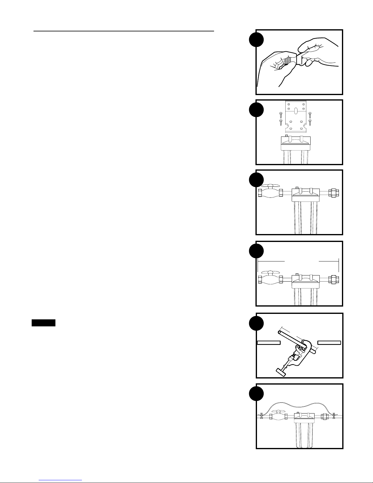
1
1. Apply about 12 inches (300 mm) of Teflon® tape in clockwise direction to pipe threads
of each fitting.
2. If mounting bracket (not supplied) is to be used, attach to cap before assembling the fittings.
NOTE: Allow 1-1/2 inches (33 mm) clearance below housing to enable filter
cartridge changes.
3. Assemble all fittings. Start adapters into cap by hand.
Use a wrench to tighten firmly.
4. Measure length (shown as X on diagram) across assembled fittings and subtract 1 inch
(25 mm) if you are installing on 3/4 inch (19 mm) pipe, or 1-1/2 inches (38 mm) if
you are installing on 1 inch (25 mm) pipe. Mark section of pipe to be removed.
5. Using a pipe cutter or hacksaw, remove marked section of pipe and thread remaining
ends. Wrap threads with Teflon tape.
DO NOT OVER-TIGHTEN.
2
3
4
x
6. Align filter assembly with ends of pipe, making certain cap opening marked “IN” is facing
the incoming water supply. It will be necessary to spread ends of pipe apart to install filter
assembly. Using two adjustable wrenches, hold incoming adapter securely with one wrench
and tighten nut with second wrench. Repeat procedure for outgoing adapter.
CAUTION: If water pipes are used to ground electrical systems, appliances, or phones, be
certain to install a jumper wire. Contact your local electrician for more information.
(Diagram 6)
Slowly turn on water supply to filter and depress red pressure-relief button on cap to
release trapped air. Check for leaks. Open nearest faucet and flush filter for 10 minutes,
wait one hour, then flush again for 10 minutes.
5
x
6
2
Page 3

Cartridge Replacement
A. Turn off water supply to filter. Depress red pressure-relief button on top of filter. Use
wrench to unscrew bottom of housing.
NOTE: If turning off water supply to filter will also turn off water supply to the rest of the
home, be sure to fill a bucket of water first to allow you to clean housing after it has been
removed.
B. Locate and remove large O-ring, wipe clean of lubricant and set aside. Discard used
cartridge. Rinse out bottom of housing and fill about 1/3 full with water. Add about 2
tablespoons of bleach and scrub cap and bottom of housing with nonabrasive sponge or
cloth. Rinse thoroughly. Lubricate O-ring with clean silicone grease. Insert O-ring back
into groove and smooth into place with finger. Insert new cartridge over standpipe in
bottom of housing.
C. Screw bottom of housing onto the cap and hand-tighten.
Turn on water supply slowly to allow filter to fill with water. Depress red pressure-relief
button to release trapped air. Check for leaks before leaving installation.
NOTE: After installation, flush the cartridge for 10 minutes, wait one hour, then flush again
for 10 minutes before using the water.
DO NOT OVER-TIGHTEN.
A
B
C
Troubleshooting
Leaks between cap and bottom of housing:
1. Turn off water supply and depress pressure-relief button.
2. Clean and lubricate O-ring with silicone grease. Also, clean the groove where the o-ring seats. Replace o-ring back in groove above threads. Screw bottom of housing
back on cap securely by hand. Do not overtighten.
3. Turn on water supply. If leaks persist, or if there are other leaks on the system, turn off water supply. Call Technical Support at 1-800-721-9243.
Leaks on inlet/outlet connections:
1. Turn off water supply. For brass fittings, tighten nut 1/2-turn with wrench.
2. Turn on water supply. If leaks persist, or if there are other leaks on system, turn off water supply. Call Technical Support at 1-800-721-9243.
Replacement Parts
1 01020826 OR-100 o-ring
2 01020822 SW-3
For replacement parts, contact your nearest retailer or call Culligan Consumer Services @ 1-800-721-7360.
The HD-950A is covered by a limited five year warranty. See warranty for details.
A housing wrench
2
1
3
Page 4

Cartridge Selection
Select the right cartridge (Model #) R50-BBSA CP5-BBS RFC-BBSA
for your water needs.
Scale and rust particles X X
Coarse sand X X
Sand/dirt/silt X
Fine dirt/silt/sand X
Extra fine dirt/silt/sand X
Bad taste & odor X
Aesthetic Chlorine: Taste & Odor X
Filter Life (in months)* 6 3 6
(gallons) 24,000 12,000 10,000
Micron Rating (Nominal)† 50 5 25
Service Flow Rate gpm (lpm)** 10 (37) 8 (30) 3 (11)
Operating Requirements
Pressure: = 30 - 100 psi (2.07 - 6.9 bar)
Temperature = 40 - 100°F (4.4 - 37.7°C)
Turbidity = 5 NTU Max.
WARNING: Do not use with water that is microbiologically unsafe or of
unknown quality without adequate disinfection before or after the system.
CAUTION: The filters must be protected from freezing. Failure to do so may result
in the cracking of the filter and water leakage.
*NOTE: Filter cartridge life varies depending on usage and water conditions
**NOTE: Flow rates measured at 60 psi (4.1 bar).
†The smaller the micron rating, the smaller the size particle the cartridge will filter. For
comparison purposes, the human hair has a diameter of approximately 70 microns.
Particles smaller than 40 microns are not visible with the human eye.
The HD-950A housing has been tested and certified by WQA against
NSF/ANSI Standard 42 for materials safety and structual integrity only.
Performance Data (RFC-BBSA)
Important Notice
Read this Performance Data information and compare the capabilities of this system with your actual water treatment needs. It is recommended that, before purchasing a water treatment system, you have your water supply tested to determine
your actual water treatment needs.
RFC-BBSA has been tested according to NSF/ANSI 42 for reduction of the substances listed below. The concentration of the indicated substances in water entering the
system was reduced to a concentration less than or equal to the permissible limit
for water leaving the system, as specified in NSF/ANSI 42.
RFC-BBSA
Substance Influent Challenge Reduction Average
Concentration Requirements Reduction
Standard 42
Chlorine 2.0 mg/L±10%
Flow Rate = 3 gpm (11.4 Lpm) Capacity = 10,000 gallons (37,900 L) or 6 months
≥50% 90.3%
Warranty
This warranty applies to the Filter Housing. It does NOT apply to any disposable filter cartridge
where life expectancy varies with the water being filtered. This warranty covers defects in material
and workmanship only for 5 full years from the original date of delivery. Culligan will replace any
part which in Culligan’s opinion is defective, unless: (1) any part of the unit has been subjected
to any type of tampering, alteration, or improper use after delivery, or (2) it has been repaired
by anyone not approved by Culligan. Our Obligation does not include the cost of shipment of
materials. Culligan is not responsible for damage in transit, and claims for such damage should
be presented to the carrier by the customer.
This product has been designed solely for use as a housing for a disposable filter cartridge. It is
NOT warranted against freezing, and neither this product nor its parts is warranted against defects
or deterioration caused by uses for which this product was not expressly intended.
THE FOREGOING WARRANTY IS EXCLUSIVE AND IN LIEU OF ALL OTHER WARRANTIES, EXPRESSED
OR IMPLIED, WHETHER ORAL OR ARISING BY USAGE OF TRADE OR COURSE OF DEALING,
INCLUDING, WITHOUT LIMITATION, ANY WARRANTIES OF FITNESS OR MERCHANTABILITY. THIS
WARRANTY IS THE PURCHASER’S SOLE AND EXCLUSIVE REMEDY, IN NO EVENT SHALL CULLIGAN
BE LIABLE FOR ANY ANTICIPATED OR LOST PROFITS, INCIDENTAL DAMAGES, CONSEQUENTIAL
DAMAGES, COSTS, TIME CHARGES OR OTHER LOSSES, WHETHER BASED ON BREACH OF
CONTRACT, TORTIOUS CONDUCT OR ANY OTHER THEORY, INCURRED IN CONNECTION WITH THE
PURCHASE, INSTALLATION, REPAIR OR OPERATION OF THE OPAQUE FILTER HOUSING. CULLIGAN
DOES NOT AUTHORIZE ANYONE TO ASSUME FOR IT ANY LIABILITY OR TO MAKE ON ITS BEHALF
ANY ADDITIONAL WARRANTIES IN CONNECTION WITH THE OPAQUE FILTER HOUSING OR ANY
PART THEREOF.
For servicing under this warranty, return any defective part to YOUR RETAILER within the 5 year
period referred to above.
Date installed:
Testing was performed under standard laboratory conditions, actual performance may vary.
Test Conditions
Flow Rate = As noted for each individual cartridge
Inlet Pressure = 60 psi (4.14 bar)
pH = 7.5 +/- 1
Temperature = 68°F +/- 5°F (20°C +/- 2.5°C)
The RFC-BBSA was tested at NSF International at a flow rate of 3.0 gpm
to a capacity of 10,000 gal and achieved 90.3% reduction of Aesthetic
Chlorine Taste and Odor.
Culligan International Company
Rosemont, Illinois 60018
www.culligan.com
©2009 Culligan International Company 03/09 01020704
Customer Service
Phone: 1-800-721-7360 Fax: 1-800-721-7390
International: Phone (920) 457-2720 • Fax (920) 457-7366
e-mail: customerservice@culligan.com
M-F 8:00 a.m – 4:30 p.m. CST
4
Sales & Marketing Correspondence
P.O. Box 1086 • Sheboygan, WI 53082-1086
Fax (920) 457-7366
e-mail: sales-marketing@culligan.com
 Loading...