

Culligan G1 Series, G1-2S, G1-3L, G1-4L, G1-1F Installation, Operation And Service Instructions
...
CULLIGAN
Cat. No. 01021713
Rev. E 04/02/13
DCO 013630
Installation,
Operation and
Service
Instructions
®
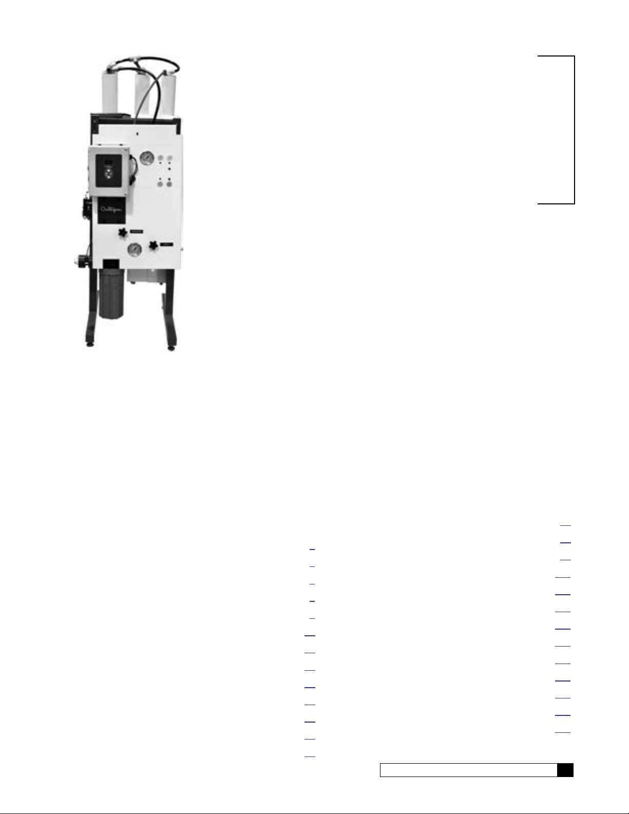
Series G1 Reverse Osmosis
Water Treatment Systems
Models from 2011
©2013 Culligan International Com pa ny
Attention Culligan Customer:
Your local independently operated Culligan dealer employs trained service and maintenance personnel who are experienced in the installation, function and repair of Culligan equipment. This publication is written specifically for these individuals and is intended for their use.
We encourage Culligan users to learn about Culligan products, but we believe that product knowledge is best obtained by
consulting with your Culligan dealer. Untrained individuals who use this manual assume the risk of any resulting property
damage or personal injury.
NOTICE Please send any suggestions for improving this manual to productmanuals@culligan.com
WARNING! Electrical shock hazard! Prior to servicing equipment, disconnect power supply to
prevent electrical shock.
WARNING! If incorrectly installed, operated, or maintained, this product can cause severe injury.
Those who install, operate, or maintain this product should be trained in its proper
use, warned of its dangers, and should read the entire manual before attempting to
install, operate, or maintain this product. Failure to comply with any warning or
caution that results in any damage will void the warranty.
CAUTION! This product is not to be used by children or persons with reduced physical, sensory
or mental capabilities, or lack of experience or knowledge, unless they have been
given supervision or instruction.
CAUTION! Children should be instructed not to play with this appliance.
CAUTION! If the power cord from the transformer to the unit looks or becomes damaged, the
cord and transformer should be replaced by a Culligan Service Agent or similarly qualified person in order to avoid a hazard.
WARNING! This device complies with Part 15 of the FCC rules subject to the two following
conditions: 1) This device may not cause harmful interference, and 2) This device
must accept all interference received, including interference that may cause undesired
operation.
This equipment complies with Part 15 of the FCC rules. Any changes or modifications not expressly approved by the
manufacturer could void the user’s authority to operate the equipment. Changes or modifications not expressly approved
by the party responsible for compliance could void the user’s authority to operate the equipment.
CAUTION! To reduce the risk of fire, use only No. 26 AWG or larger telecommunications line
cord.
NOTE This system is not intended for use with water that is microbiologically unsafe or of unknown quality
without adequate disinfection either before or after the system.
NOTE Check with your public works department for applicable local plumbing and sanitation codes. Follow
local codes if they differ from the standards used in this manual. To ensure proper and efficient operation of the Culligan equipment to your full satisfaction, carefully follow the instructions in this manual.
Products manufactured and marketed by Culligan International Company (Culligan) and its affiliates are protected by patents issued or pending in the United States and other countries. Culligan reserves the right to change the specifications
referred to in this literature at any time without prior notice. Culligan, Aqua-Sensor, Tripl-Hull, and SoftMinder are trademarks of Culligan International Company or its affiliates.
Culligan International Company
9399 West Higgins Road, Suite 1100
Rosemont, Illinois 60018
1-847-430-2800
www.culliganmatrixsolutions.com
Culligan®
Installation
and
Operation
Instructions
Series G1 Reverse Osmosis
Water Treatment Systems
Models From 2011
Contents
Introduction ........................................................................ 1
G1 RO Features ................................................................ 2
G1 RO Series Specifications ............................................. 4
G1 RO System Configurations .......................................... 5
G1 RO Installation ............................................................. 6
GBE RO Controller Program Data................................... 19
First Time Setup .............................................................. 20
Basic Operation ............................................................... 31
Setup ............................................................................... 32
Accessories ..................................................................... 41
Error Limits ...................................................................... 58
System Operating Information ......................................... 60
Service and Maintenance ................................................ 62
GBE RO Controller Menu Structure ................................ 76
G1 RO Parts Diagrams and Lists .................................... 80
Flow Diagram .................................................................. 99
Electrical Installation ...................................................... 101
GBE RO Controller Wiring ............................................. 102
Remote Display Template ............................................. 103
Appendix A G1 RO International ............................. 104
Appendix B Basic Principles ...................................... 121
Appendix C Menu and Key Navigation ...................... 123
Appendix D Quick Programming Guide .................... 125
Appendix E Data Port Output .................................... 129
Appendix F Programming Log ................................... 133
Index .............................................................................. 134
Cat. No. 01021713
i
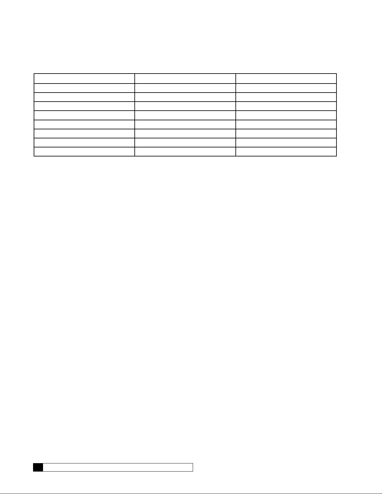
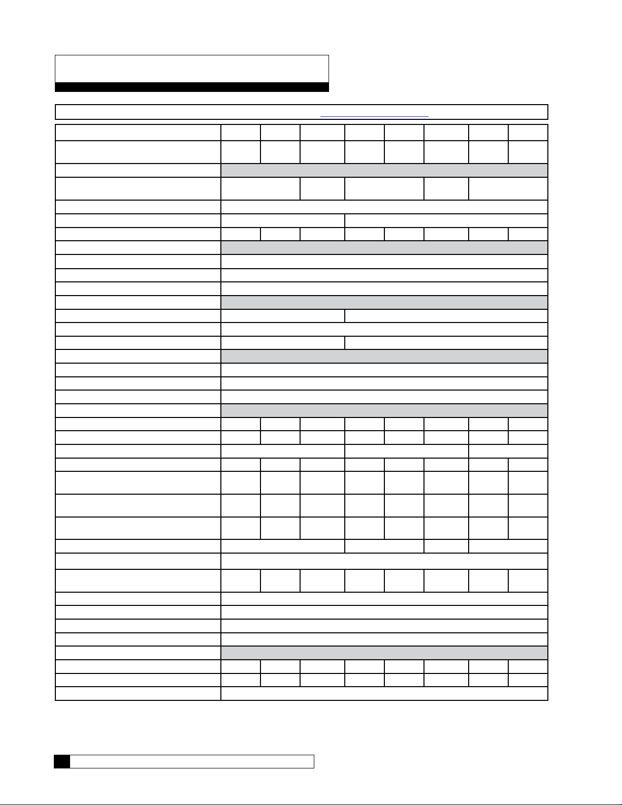
Units of Measure Conversion: U.S. to Metric
Convert From To Multiplication Factor
gallons per minute (gpm) liters per minute (l/min) 3.785
gallons per day (gpd) cubic meters per hour (m^3/hr) 0.000158
gallons (gal) liters (l) 3.785
pounds per square inch (psi) bar 0.0689
degrees Fahrenheit (F) degrees Centigrade (C ) (F-32) x 0.556
pounds (lbs) kilograms (kg) 0.4536
Inches (in) millimeters (mm) 25.4
parts per million (ppm) mg/l 1.00
ii Culligan® Series G1 Reverse Osmosis
ii Cat. No. 01021713
Introduction
Read this Manual First
Before you operate the Culligan® Series G1 reverse osmosis systems, read this manual to become familiar with the
device and its capabilities.
®
Culligan
manual contains important information about the unit, including information needed for installation, operating, and maintenance procedures. A troubleshooting section provides a guide for quick and accurate problem solving.
In order for the water treatment system to continue to provide high quality water, you must develop a thorough understanding of the system and its operation. Review this manual before making any attempt to install, operate, or service
the system. Installation or maintenance done on this system by an untrained service person can cause major damage to
equipment or property damage.
About this Manual
This manual:
This publication is based on information available when approved for printing. Continuing design refinements could cause
changes that may not be included in this publication.
Series G1 reverse osmosis systems are designed to meet the needs of applications for high quality water. This
• Familiarizes the operator with the equipment
• Explains installation and setup procedures
• Provides basic programming information
• Explains the various modes of operation
• Gives specifications and troubleshooting information
Safe Practices
Throughout this manual there are paragraphs set off by special headings.
Notice
Notice is used to emphasize installation, operation or maintenance information which is important, but does not present
any hazard. For example,
NOTICE The nipple must extend no more than 1 inch above the cover plate.
Caution
Caution is used when failure to follow directions could result in damage to equipment or property. For example,
CAUTION! Disassembly while under water pressure can result in flooding.
Warning
Warning is used to indicate a hazard which could cause injury or death if ignored. For example,
WARNING! Electrical shock hazard! Unplug the unit before removing the timer mechanism or
cover plates!
The CAUTION and WARNING paragraphs are not meant to cover all possible conditions and situations that may occur. It
must be understood that common sense, caution, and careful attention are conditions which cannot be built into the equipment. These MUST be supplied by the personnel installing, operating, or maintaining the system.
Be sure to check and follow the applicable plumbing codes and ordinances when installing this equipment. Local codes
may prohibit the discharge of acid or caustic solutions to drain. An extra solution tank should be used to neutralize the
solution before discharging to drain.
Use protective clothing and proper face or eye protection equipment when handling chemicals or power tools.
Cat. No. 01021713
Introduction 1

G1 RO Features
The Series G1 Reverse Osmosis systems are the direct result of Culligan’s long time experience in membrane applications around the world. From process water for any size business to treating water for an entire city, Culligan has the
knowledge and the range of products you need to get the job done.
The Series G1 reverse osmosis system is sized to serve many small-to-medium-sized applications that require high-quality reverse osmosis water. It is designed with the flexibility to closely match your treatment requirements from 0.35 to 2.8
gallons per minute (500 to 4,000 gallons per day). Mount the system on a wall to save floor space, or install it on the floor
using an optional floor stand. A rich standard feature set with multiple options can satisfy virtually any application. Select
the right size and choose any options needed to complete your system.
Key G1 RO System Features
• Simple System Integration
• Global Product Platform
• Flexible Configurations
• Quick Delivery/Easy Installation
• Exclusive Culligan Advanced Electronics
• Multiple Languages
• Historical Operating Data
• Alarm Recognitions
• US Standard and Metric Readings
• Remote Monitoring Options for connection to a control room PLC
• Telemetry Options
• Real Time Clock: tracks date and time has five-year battery back up.
• TDS Probe: TDS probe measures product water quality.
• Remote Alarm Output Connection (Optional): Provides either a N.O. or N.C. Dry Contacts. This feature can be
used to activate an alarm or programmed into a customers (DCS) building alarm system.
GBE RO Controller Features
System Computes Normalized Flow
The system computes normalized flow and can be set to trigger an alarm if the normalized flow drops below a specified
limit.
Power Up Mode
The system can be configured to either go to standby mode or to automatically return to making RO water in the event of
power loss and restoration.
Storage Tank and Pressure Logic
The system has the ability to monitor high and low level switches in an atmospheric storage tank and a pressure switch in
a pressurized storage tank to automatically put the system into standby mode when the tank is full.
Pretreatment Lockout
Allows for single softener or filter pretreatment that can be set to go into regeneration or backwash cycle at low water use
periods and have the RO in standby until cycle is completed. RO product water tank would need to be sized correctly
based on flow demand if continuous RO product water is required.
GBE Historical Data
The GBE RO Controller stores basic performance data over the lifetime of the membranes as an aid to optimizing RO
performance and determining when the membranes need to be cleaned or replaced.
2 Culligan® Series G1 Reverse Osmosis
2 Cat. No. 01021713

Flush Options
The system offers six different membrane flush modes to improve performance and extend membrane life.
NOTE Quality Flush and Permeate Flush are mutually exclusive optional features.
Target TDS
The RO system keeps track of the average product water TDS whenever the RO system is operating, mixing lower quality
water with product water to meet the average product water TDS.
Communications via Modem
An optional modem and monitoring service can be used to remotely monitor the RO performance over time. This service
can also be used to alert the customer and the Culligan dealer in the event that an alarm or error condition occurs.
Wireless Remote Communication
An optional wireless remote can display the current operational status and performance statistics up to 200 feet from the
G1 RO system.
PLC Outputs Available
The GBE Controller collects data once per minute and then streams the data to a customer-owned PLC for data collection
or monitoring. Customer would have to write code to take text information and convert the data for their data collection
system. For more information, see Culligan P/N 01021512 Advanced Communication Manual.
This data, once converted from a text stream, can easily be imported to an excel spreadsheet and the data logged can
then be graphed and trended.
Cat. No. 01021713
G1 RO Features 3
G1 RO Series Specifications
NOTE Specifications for G1 RO 230V (international) are in Appendix A on page 104.
G1-2S G1-3S G1-4S G1-2L G1-3L G1-4L G1-1F G1-2F
Nominal Capacity, GPD [m³/hr]* 500
[0.08]
Dimensional, Series G1 Units
Width - in [mm] 34.5 [876] 38.5
Depth - in [mm] 8.7 [221]
Height - in [mm] 34.8 [884] 45.5 [1156]
Operating Weight, lb [kg] 81 [37] 92 [42] 96 [44] 88 [40] 103 [47] 111 [50] 97 [44] 129 [59]
Unit Connections
Inlet (Tube) - in. 1/2
Product (Tube) - in. 1/2
Concentrate (Tube) - in. 3/8
Electrical
Motor Horsepower, hp [kW] 0.333 [0.25] 0.75 [0.56]
Power Requirement (VAC/Hz/phase) 115/60/1
Full Load Current, amp (@115V) 8 12
Hydraulic - Prefilter
Housing Quantity 1
Cartridge Rating, micron 5
Cartridge Length - in [mm] 10 [254]
Hydraulic - RO
RO Housing Quantity 2 3 4 2 3 4 1 2
RO Element Quantity 2 3 4 2 3 4 1 2
RO Element Size - in 2.5x21 2.5x40 4x40
RO Array 1:1 1:1:1 1:1:1:1 1:1 1:1:1 1:1:1:1 1 1:1
Product Flow - gpm [L/min]* 0.35
[1.32]
Concentrate Flow - gpm [L/min]* 0.35
[1.32]
Required Inlet Feed Flow gpm [L/min] 0.7
[2.65]
Pump Flow @ 150 psi, gpm [Lmin] 1.6 [6.06] 2.7 [10.44]
Maximum Module Feed Pressure psig [kPa] 150 [1034]
Nominal Module Feed Pressure psig [kPa]† 100
[689]
Max. Product Pressure psig [kPa] 40 [275.6]
Inlet Pressure Min., dynamic psig [kPa] 20 [137.8]
Maximum, dynamic psig [kPa] 50 [344.5]
Operating Temp °F [°C] 33-100 [1-38]
Recovery (%)*
Design 50 50 50 50 50 50 25 50
Minimum 40 40 40 40 40 40 15 40
Salt Rejection, Nominal (%) 98
†Calculated using a 0.85 fouling factor
*Nominal capacity based on new RO membranes operating on a properly pretreated feed water of 500 ppm TDS as NaCl,
77 °F (25 °C), Silt Density Index (SDI) below 3, and supplying water to atmosphere. Productivity will vary depending on
the actual feed water quality and temperature.
4 Culligan® Series G1 Reverse Osmosis
750
[0.12]
0.52
[1.97]
0.52
[1.97]
1.04
[3.94]
103
[709.7]
1000
[0.16]
[978]
0.69
[2.61]
0.69
[2.61]
1.38
[5.22]
104
[716.6]
1200
[0.19]
0.83
[3.14]
0.83
[3.14]
1.66
[6.28]
96
[661.4]
1700
[0.27]
34.5 [876] 38.5
1.18
[4.47]
1.18
[4.47]
2.36
[8.93]
97
[668.3]
2200
[0.35]
[978]
1.53
[5.79]
1.53
[5.79]
3.06
[11.58]
3.1 [11.73]
101
[695.9]
4 Cat. No. 01021713
2000
[0.32]
34.5 [876]
1.40
[5.30]
4.17
[15.78]
5.56
[21.04]
5.6 [21.2]
95
[654.6]
4000
[0.63]
2.8
[10.6]
2.78
[10.52]
5.56
[21.04]
101
[695.9]
G1 RO System Configurations
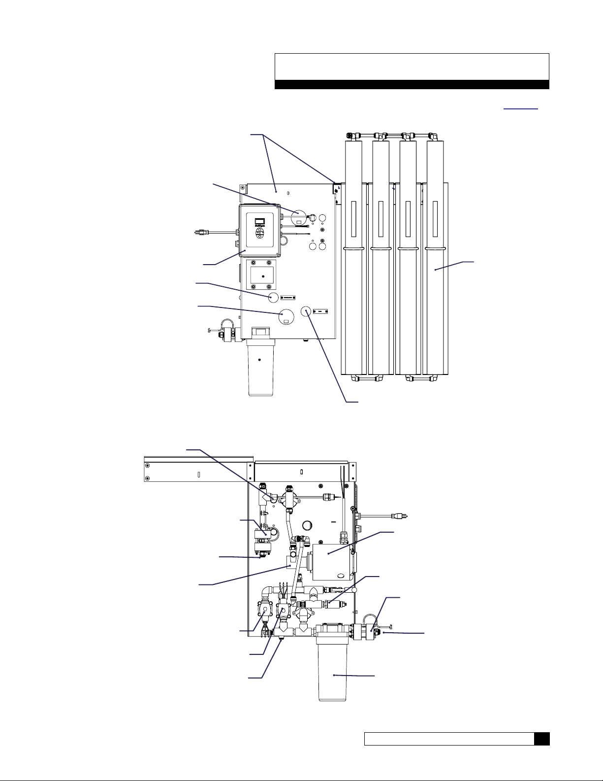
A G1-4L is pictured in Figure 1 and Figure 2. Width of membrane rack varies with model. See parts section on page 80
for a list of component part numbers.
MOUNTING BRACKETS
MEMBRANE FEED PRESSURE
GBE RO CONTROLLER
RECIRCULATION CONTROL
INLET FEED PRESSURE
TDS SENSOR
PRODUCT FLOW METER
MEMBRANES
WASTE CONTROL
Figure 1. G1 RO front view.
MOTOR
PRODUCT WATER OUTLET
Cat. No. 01021713
PUMP
FAST FLUSH SOLENOID
INLET SOLENOID
WASTE WATER OUTLET
PRESSURE SWITCH
FEED FLOW METER
FEED WATER INLET
PREFILTER
Figure 2. G1 RO back view.
G1 RO System Configurations 5
G1 RO Installation
Unpacking the G1 RO
This manual, the warranty, and registration card are packed in the control assembly box. Please complete the registration
card and mail it promptly.
NOTICE Examine each component carefully to check for loose or damaged parts. Report any apparent or
concealed shipping damage to the freight carrier immediately.
Materials Required
To install the system, the following items are required:
• Level
• Drill
• Screws for mounting the bracket for the main plumbing assembly
• Screwdrivers, including a small, flat-bladed (1/8” wide) screwdriver for wiring
• Adjustable wrench
• Tubing;
All—Nat 1/2” Feed Water and Product Water Tubing, P/N 00901801
All—Nat 3/8” Product Concentrate (Waste) Water Tubing, P/N 00444973
• 1-Gallon Bucket calibrated for taking flow rates
• Stopwatch
• Calculator
• Clean rags
• Thermometer
• Portable Total Dissolved Solids meter
• Safety glasses
Unpacking
The G1 reverse osmosis unit requires some assembly. Please check your order thoroughly to make sure you have the
following items. Refer to the table for box quantities.
• Pump/Motor Panel
• Housing Assemblies
• Membranes
• Fitting Kit
Location
The Series G1 unit is designed for wall mounting so that all components are accessible for maintenance and monitoring.
The wall you choose for mounting the unit must be capable of supporting at least 130 pounds. See the assembly section
below for installation detail.
A 120 VAC/60 Hz/1 Phase grounded electrical receptacle with 15 amp fuse protection is required for use with the six-foot,
three-wire power cord.
NOTICE Do NOT use any bolt size smaller than 1/4" diameter.
The unit must be located near a drain able to handle 10 gallons per minute (37.9 liters/min). This is in addition to the flow
from any other water treatment equipment.
CAUTION! The system must not be located near any corrosive chemicals which may cause fail-
ure of the plastic or metal parts of the unit. In addition, do not locate the unit where the
temperature may exceed the feed water temperature limits.
6 Culligan® Series G1 Reverse Osmosis
6 Cat. No. 01021713
Assembly
Bracket
Concrete Wall Installation
Refer to Figure 3 to install the G1 RO system to a concrete wall. Place the unit against the wall, level the unit and mark
the wall through the mounting holes. Drill the holes in the wall and mount the unit. Horizontal holes are on 16" centers.
Vertical holes are on 2" centers.
Wall Mounting Kit (optional)
If the wall is not concrete and wall mounting is necessary, a wall mounting bracket kit is available. The bracket has holes
for mounting on 18” and 20”centers. Use bracket P/N 01023017 for all models.
Place the bracket adapter on the wall with the flat side towards the wall. Level the bracket adapter and mark the wall
through the appropriate holes. Drill holes in the wall. Assemble the wall brackets to the bracket adapter. Mount the adapter and wall brackets to the wall. Mount the pump/motor assembly and the membrane assembly to the brackets.
Align with 20" studs
Align with 18" studs
Mount
To Wall
Wall Mount
Bracket Adaptor
Mounting
Figure 3. G1 RO wall mount bracket kit, P/N 01022077 (included with unit) and optional bracket adapter.
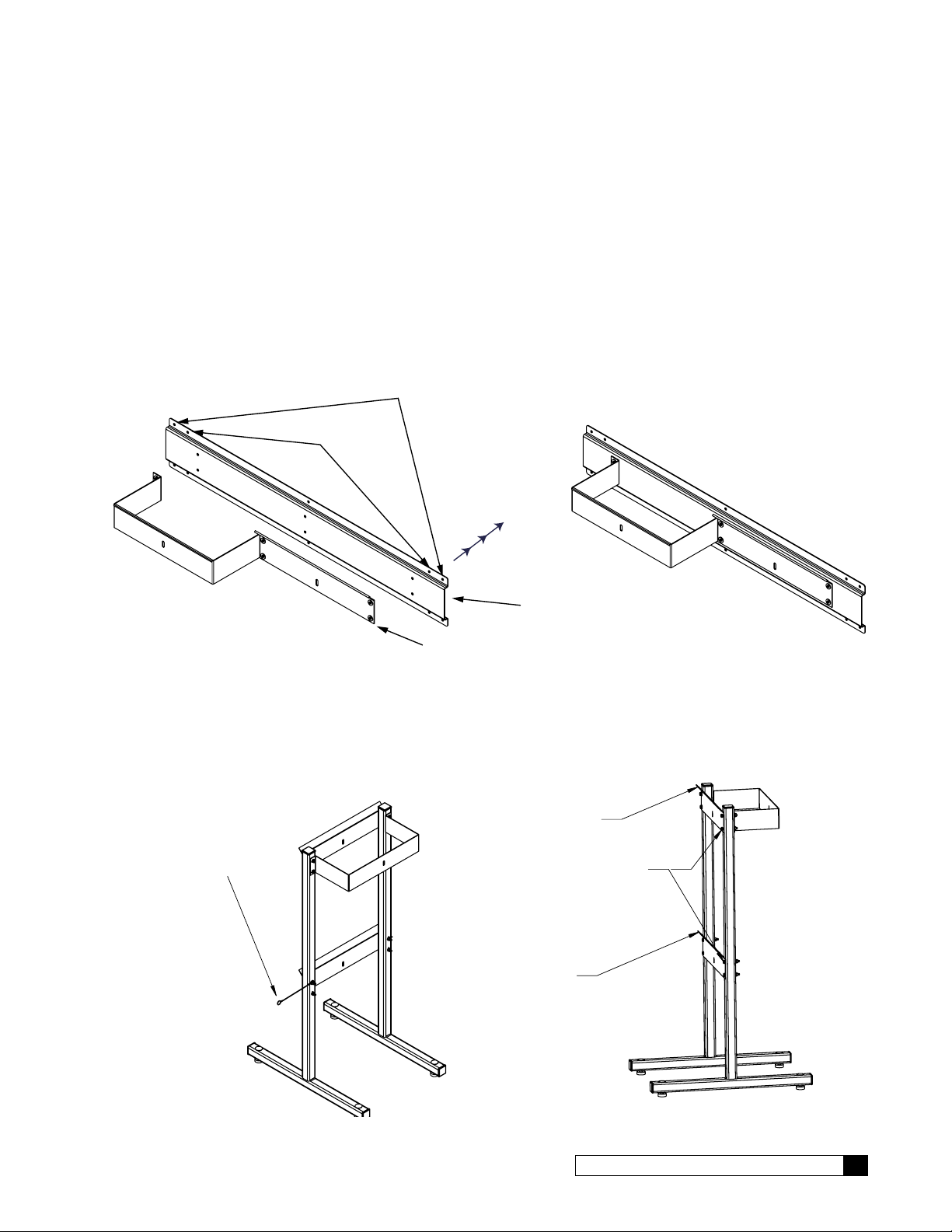
Stand Mounting (optional)
If the RO unit requires floor mounting, a rigid steel stand (P/N 01021987, Figure 4) is available. Wall mount brackets are
used with floor stand to mount unit and membranes.
NOTE DIRECTION
ANGLED FACE UP
LANYARD
NOTE DIRECTION
ANGLED FACE UP
BOLT HEADS
THIS SIDE
Cat. No. 01021713
Figure 4. G1 RO floor assembly.
G1 RO Installation 7
Pump/Motor Panel
Mounting Bracket
Pressure
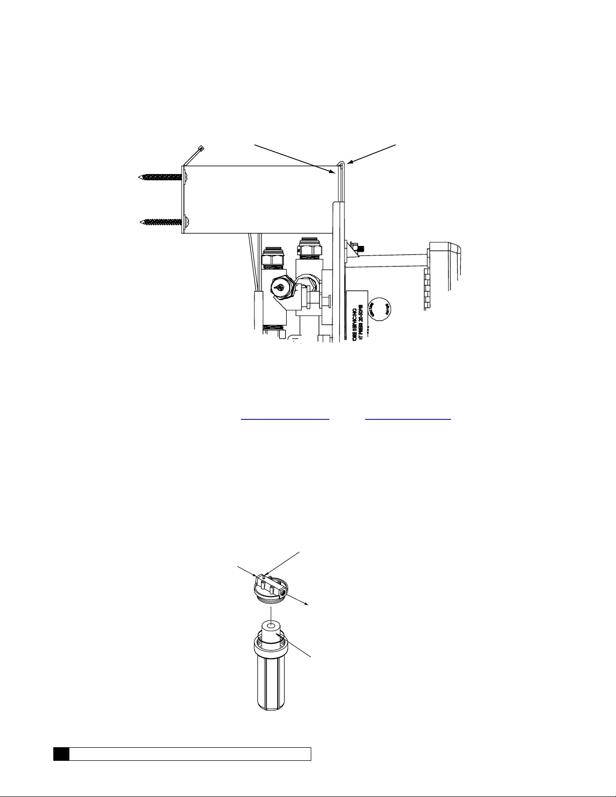
Hang the pump motor panel on the mounting bracket. The top edge of panel hooks on to the bracket. See Figure 5.
Motor Panel
Figure 5. Pump motor panel hanging on mounting bracket.
Fittings
Locate the Membrane Fitting Kit that was shipped with the unit. This kit includes all the fittings needed to connect the
membranes to the pump/motor panel. Refer to Figure 11 on page 13 through Figure 15 on page 17 for the model
you are installing and follow the tubing diagram. Detailed drawings of the fittings and housings can be found in the parts
section.
Prefilter Cartridge
1. Locate the prefilter cartridge packed with the main unit.
2. Unscrew the prefilter bowl.
3. Lubricate the seal ring with silicone lubricant as required.
4. Remove the paper wrapper from the cartridge, place the cartridge in the bowl, and screw the bowl onto the
head.
Inlet
Figure 6. Installing the Prefilter.
Relief
Button
Outlet
Filter Cartridge
8 Culligan® Series G1 Reverse Osmosis
8 Cat. No. 01021713
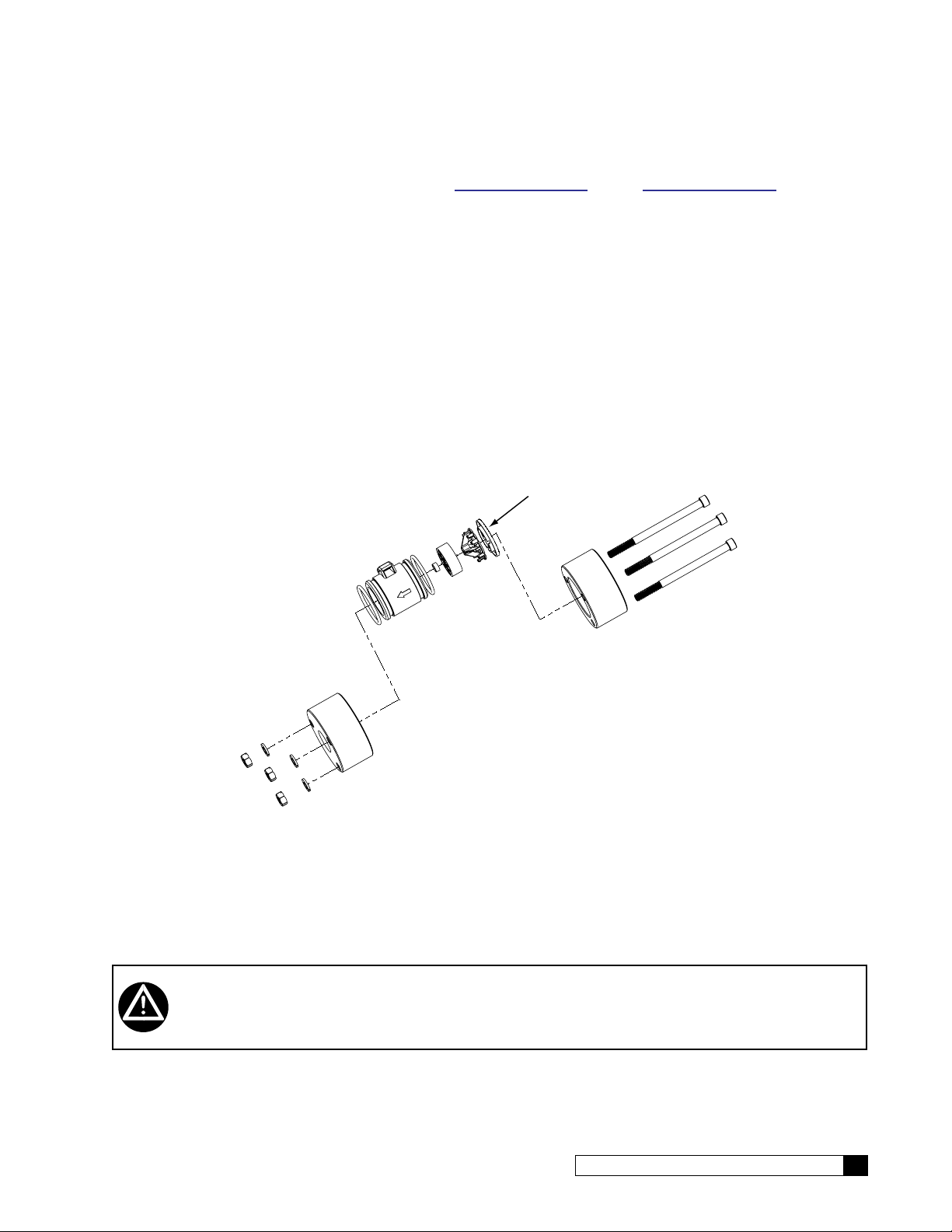
Feed Flow Meter
Screws
1. Install the feed flow meter on the prefilter.
2. Install the flow meter cable.
2
1
Figure 7. Feed flow meter installed on prefilter.
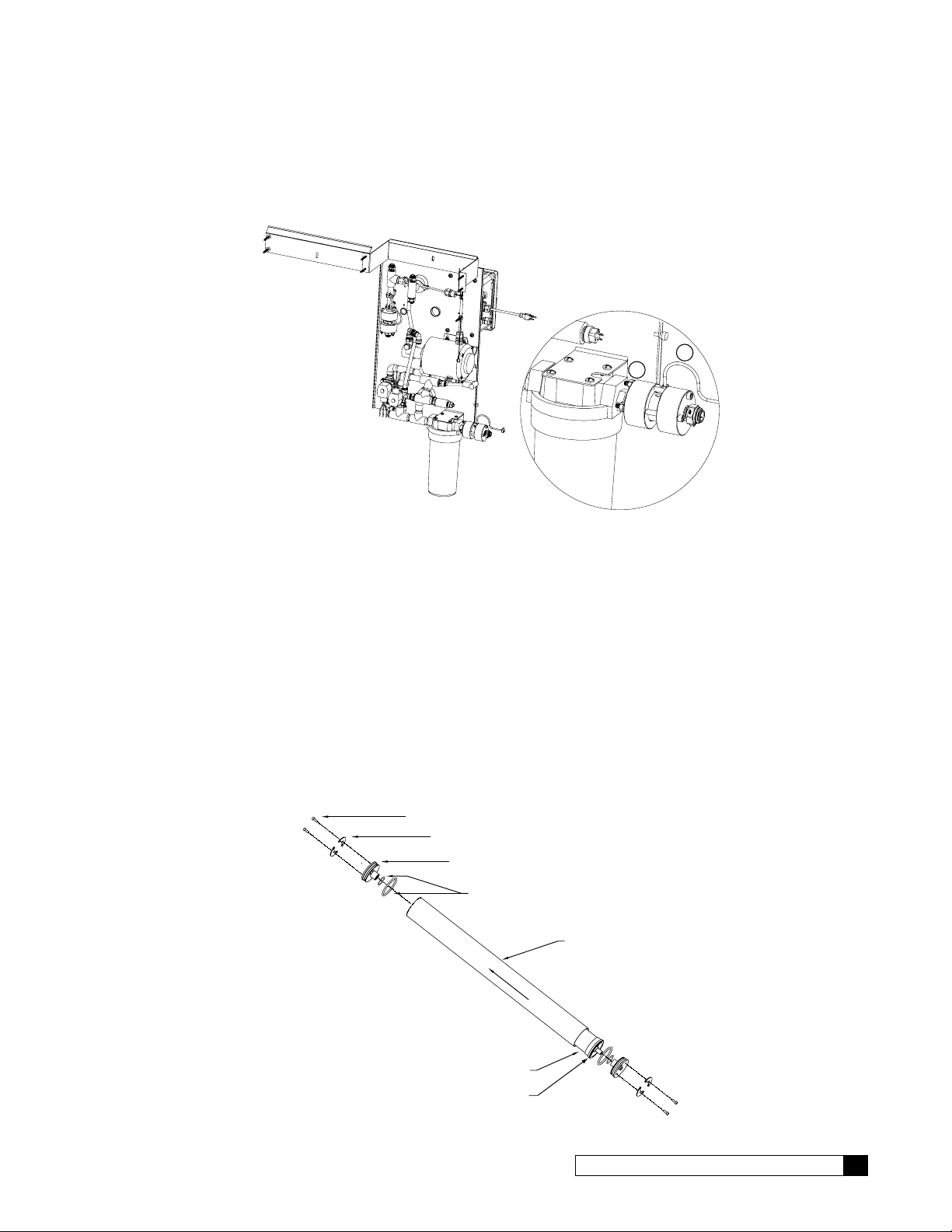
Membranes
Before mounting the membrane housings, the membranes must be inserted into the housings. Take care to not damage
the end cap O-rings or membrane brine seal.
The membranes are shipped in a sealed package. Use extreme caution when opening the package with a sharp instrument. Any damage to the membrane can cause poor quality coming from the unit.
1. The membrane housings have directional arrows on them that indicate direction of flow. Install the membranes
in the direction of flow. Open the housing end opposite the direction of flow.
2. Remove the end caps from all vessels by removing the two Allen head screws that hold down the retaining
clips. The clips are pushed into an internal groove in the housing, so completely remove the screws so the clip
can be slid out of the groove. Note placement of the caps to assure reinstallation in the same orientation.
3. Check the O-ring seals on the membrane and end plug, and the membrane brine seal for damage. If an O-ring
is cut or crimped, it may cause high flow and poor quality. Replace any suspicious O-rings.
Cat. No. 01021713
Retaining Rings
End Cap
O-Rings
Housing
FLOW
Membrane
Brine Seal
Figure 8. Membrane and its housing.
G1 RO Installation 9

4. Remove a new membrane from its plastic bag. Lightly lubricate the O-rings with a silicone-based lubricant or
TO MEMBRANE
use a mixture of 70% glycerin and 30% water.
CAUTION! Do not use a petroleum-based lubricant. It will damage the synthetic rubber and the
membrane.
5. Install the membrane in the same direction as indicated by the arrow on the outside of the membrane vessel.
The brine seal end should go in last.
6. Repeat for the remaining membrane housings. There may be from one to four housings on each model.
G1 Tubing Configuration
A
FEED (1/2" TUBE)
FROM MEMBRANE
C
PRODUCT 1/2" TUBE
B
FROM MEMBRANE
CONCENTRATE 3/8" TUBE
SYSTEM PRODUCT
OUTLET 1/2" TUBE
SYSTEM INLET
1/2" TUBE
SYSTEM WASTE
(CONCENTRATE) 3/8" TUBE
Figure 9. G1 tubing configuration.
WARNING! The system must be grounded. An improperly grounded unit could cause injury from
electrical shock!
10 Culligan® Series G1 Reverse Osmosis
10 Cat. No. 01021713
Plumbing Installation
Low Flow Nozzle
Refer to the appropriate tubing installation instructions (Figure 11 on page 13 through Figure 15 on page 17) for
further information.
Feed Water Connections
Connect tubing to the Feed water inlet. Observe the following:
1. To minimize pressure loss, the tubing size should be at least 1/2”.
2. Install an optional pressure gauge (P/N D1006272) before the pre-filter. This allows you to measure the pres-
sure differential across the filter cartridge.
3. Install a tee, with a shutoff valve on the branch, before the feed flow meter to provide a connection for introduc-
ing cleaning solutions.
4. If necessary, install a pressure regulator (50 psi downstream max. setting) in the inlet plumbing, to assure con-
stant pressure and to prevent harmonic vibration.
5. Install a shutoff valve in the inlet plumbing to simplify maintenance and service.
6. If the feed water can be used for a short period, install bypass plumbing around the unit.
Figure 10. Feed meter and nozzle.
Concentrate Water Connections
1. Direct 3/8" piping to drain from the outlet of the unit.
2. To prevent siphoning of the water in the unit to drain, raise the concentrate piping above the level of the mod-
ules and provide an anti-siphon loop.
WARNING! An air gap must be provided between the end of the concentrate tubing and the drain
to prevent back-siphoning of drain contents.
Cat. No. 01021713
G1 RO Installation 11
Product Water Connections
The product water exits the unit at the product flow meter on the back side of the unit. Connect the product tubing to the
fitting on the flow meter assembly. The product water flow meter contains a nozzle that is used with all models EXCEPT
G1-1F and G1-2F.
CAUTION! This unit produces high quality product water. This water can be contaminated by
plumbing following the unit or it can corrode the plumbing. Use only plumbing components of inert material that are compatible with the application.
The connection of the main product tubing to service plumbing will depend on how the product water will be stored.
CAUTION! Reverse osmosis elements will fail immediately if pressurized product water is allowed
to flow backward into the Series G1 unit.
12 Culligan® Series G1 Reverse Osmosis
12 Cat. No. 01021713
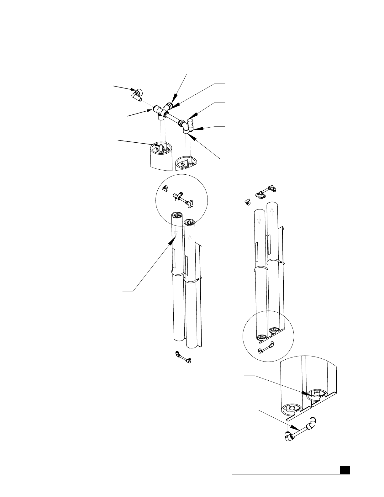
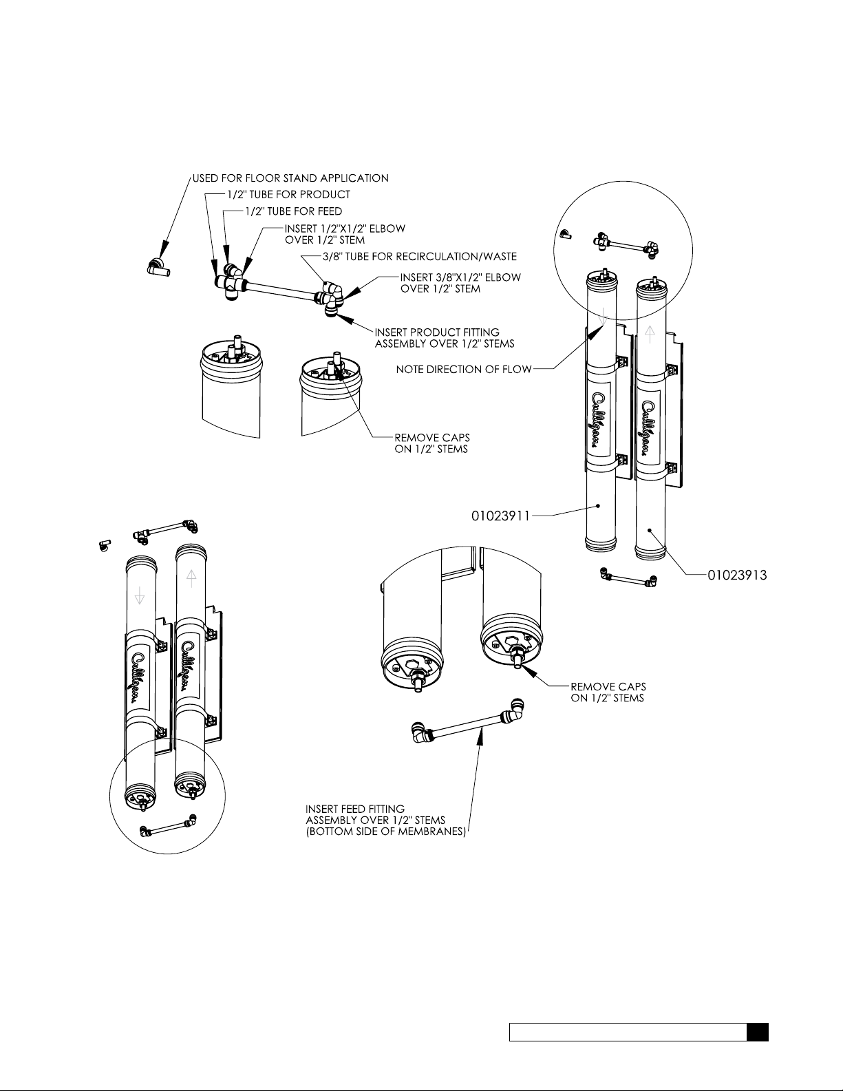
2S/2L Tubing Assembly Instructions
1/2" TUBE FOR FEED
USED FOR FLOOR
STAND APPLICATION
1/2" TUBE
FOR PRODUCT
REMOVE CAPS
ON 3/8" STEMS
INSERT 1/2"X3/8" ELBOW
OVER 3/8" STEM
3/8" TUBE FOR RECIRCULATION/WASTE
INSERT 3/8"X3/8" ELBOW
OVER 3/8" STEM
INSERT PRODUCT FITTING
ASSEMBLY OVER 3/8" STEMS
NOTE DIRECTION
OF FLOW
Cat. No. 01021713
REMOVE CAPS
ON 3/8" STEMS
INSERT FEED FITTING
ASSEMBLY OVER 3/8" STEMS
(BOTTOM SIDE OF MEMBRANES)
Figure 11. RO 2S/2L tubing assembly instructions.
G1 RO Installation 13
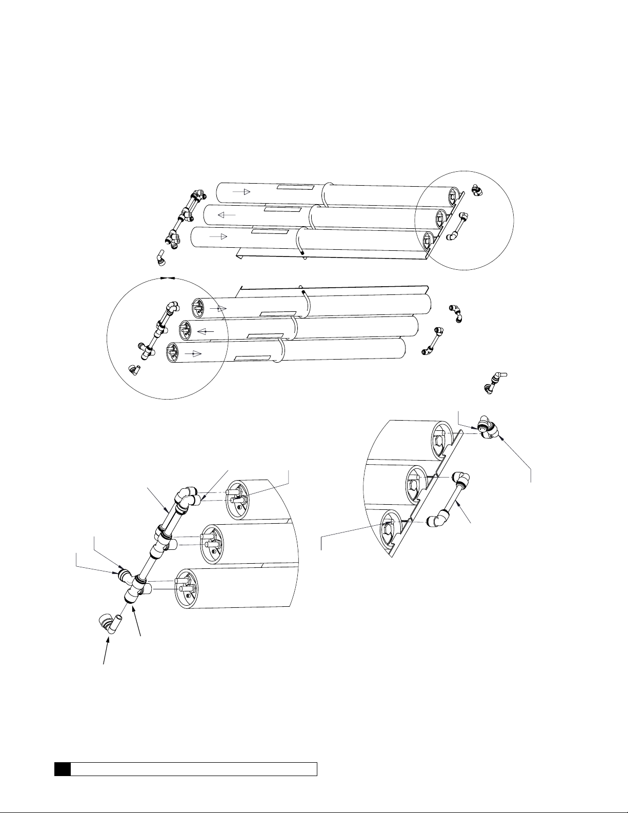
3S/3L Tubing Assembly Instructions
STAND APPLICATION
NOTE DIRECTION
OF FLOW
3/8 STEM ELBOWS, TO
BE INSERTED INTO
RECIRCULATION ASSEMBLY
ON MOTOR PANEL (M1/G1-ONLY)
3/8" TUBE FOR
RECIRCULATION/WASTE
INSERT 1/2"X3/8" ELBOW
OVER 3/8" STEM
1/2" TUBE FOR FEED
USED FOR FLOOR
INSERT FEED FITTING
ASSEMBLY OVER
3/8" STEMS
1/2" TUBE
FOR PRODUCT
Figure 12. RO 3S/3L tubing assembly instructions.
REMOVE CAPS
INSERT PRODUCT FITTING
ASSEMBLY OVER 3/8" STEMS
ON 3/8" STEMS
REMOVE CAPS
ON 3/8" STEMS
INSERT 3/8" FITTING ASSEMBLY
OVER 3/8" STEM
ASSEMBLY OVER 3/8" STEMS
(BOTTOM SIDE OF MEMBRANES)
INSERT FEED FITTING
14 Culligan® Series G1 Reverse Osmosis
14 Cat. No. 01021713
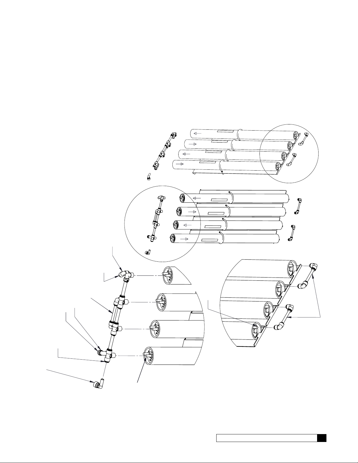
4S/4L Tubing Assembly Instructions
NOTE DIRECTION OF FLOW
REMOVE CAPS
ON 3/8" STEMS
INSERT 3/8"X3/8" ELBOW
OVER 3/8" STEM
3/8" TUBE FOR RECIRCULATION/WASTE
INSERT FEED FITTING
ASSEMBLY OVER 3/8" STEMS
INSERT 1/2"X3/8" ELBOW
OVER 3/8" STEM
1/2" TUBE FOR FEED
1/2" TUBE FOR PRODUCT
USED FOR FLOOR STAND APPLICATION
REMOVE CAPS
ON 3/8" STEMS
INSERT FEED FITTING
ASSEMBLIES OVER 3/8" STEMS
(BOTTOM SIDE OF MEMBRANES)
Cat. No. 01021713
Figure 13. RO 4S/4L tubing assembly instructions.
G1 RO Installation 15
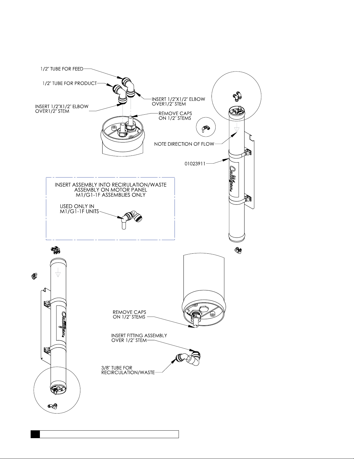
1F Tubing Assembly Instructions
Figure 14. RO 1F tubing assembly instructions.
16 Culligan® Series G1 Reverse Osmosis
16 Cat. No. 01021713
2F Tubing Assembly Instructions
Cat. No. 01021713
Figure 15. RO 2F tubing assembly instructions.
G1 RO Installation 17
Pressurized Storage Tank
The product water can be stored in a pressurized storage tank with the reverse osmosis unit controlled by a pressure
switch. Use the same components used for direct feed (see Figure 16). The pressure switch needs to be wired to the control panel as a float switch (see Figure 57 on page 105 for G1 standard wiring). A pressurized water storage kit is available for the G1 under P/N D1013880 (110V) or P/N D1018976 (220V). Connect the product tubing to a bulkhead fitting at
the top of the storage tank such as P/N 01005095 (2-gallon), P/N 01004776 (3-gallon), or P/N 01004765 (9-gallon).
Non-Pressurized Product Water Storage Tank
Depending on the type of application, a level control may be required to turn the unit off when the storage tank is full.
Install the level control according to the instructions provided with the control. See “GBE RO Controller Basic sub-panel
wiring.” on page 105 for electrical connections.
NOTICE If a repressurization pump is used, an additional level control is recommended to prevent the
pump from running dry if the storage tank is empty.
To maintain high water quality, a hydrophilic air vent filter, vacuum breaker, pop-off valve, ultraviolet lamp, and pressure
relief valve may be required.
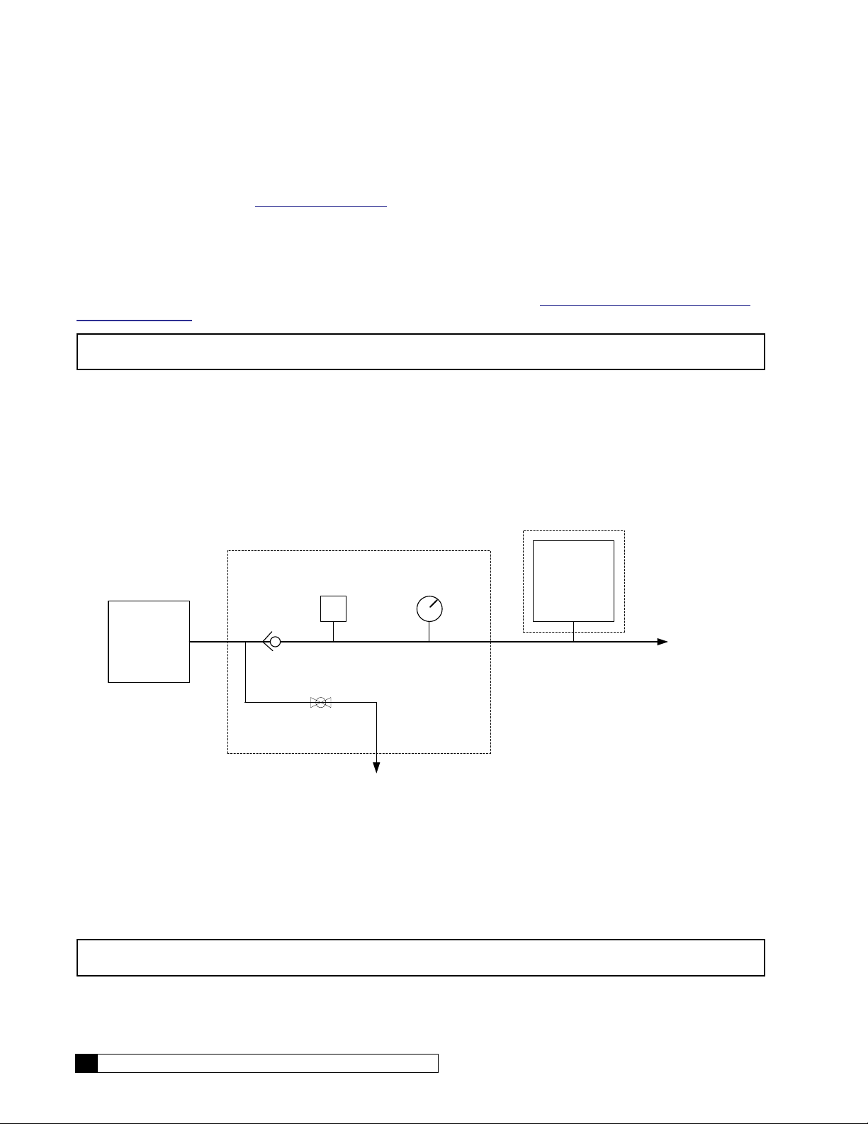
Direct Feed
If the product water is to be used directly, without storage, a few precautions are necessary to prevent damage to the
elements. Install a pressure gauge, pressure relief valve, and a normally-open (“dump”) solenoid in the product water
line as shown in Figure 16, or use pressurized storage kit (P/N D1013880). The pressure gauge will allow the operator to
monitor the product water pressure. The relief valve, which should be set to open at 40 psig, will prevent the product water
pressure from exceeding 40 psi. The dump solenoid will relieve all pressure when the unit is off.
2SWLRQDO
3UHVVXUL]HG
6WRUDJH
7DQN
7R 6HUYLFH
52 6\VWHP
&KHFN
9DOYH
3UHVVXUH 6ZLWFK
36
3UHVVXUH *DXJH
69
3UHVVXUL]HG
6WRUDJH .LW
'
7R 'UDLQ
8VH RI 3UHVVXUL]HG 6WRUDJH7DQN UHTXLUHVXVH RI 3UHVVXUL]HG 6WRUDJH .LW'
Figure 16. Direct feed connection.
Wire the direct feed/pressurized storage solenoid valve in parallel with the motor.
Valve SV4 closes when the RO pump runs; SV4 opens when the pump stops, allowing all membrane back proessure to
be relieved.
NOTICE Product back pressure will decrease the net pressure pushing water through the reverse osmosis
elements. Therefore, the flow of product water will decrease.
18 Culligan® Series G1 Reverse Osmosis
18 Cat. No. 01021713

GBE RO Controller Program Data
Program Data Input
There are a few items to note that can make programming the Culligan® Global RO Controller easier:
Slew Rates This term refers to the speed at which the display moves through the input of material. For ex-
ample, holding down the up arrow key for (5) seconds when inputting minutes for Time of Day
will cause the minutes to pass in (10) minute blocks of time. Press the up arrow or down arrow
keys for shorter periods (less than 5 seconds) will slow the rate. To move through the programming slowly, do not hold down the up arrow or the down arrow keys.
Beeper A beeper is available to assist the user by providing an audible tone (about 70 decibels) to signi-
fy valid (one beep) and invalid (three beeps) key presses. The beeper can be deactivated in the
programming mode. (If error occurs, beep will still sound even if set to “No” programming.)
Programming
Mode Timeout
Program Input
Acceptance
If there is no keypad activity for a one (1) minute period while in the programming mode, the
controller will exit the programming mode and return to the main display. Any setting that was
changed prior to the control timing out will revert to the original value. Pressing the CHECK
MARK button saves the setting.
For programming information to be accepted, the check mark key must be depressed prior to
programming mode timeout.
Cat. No. 01021713
GBE RO Controller Program Data 19
First Time Setup
First Time Setup Procedure
If at any time you need to re-run the First Time Setup, refer to “Menu Default—Rerun First Time Setup” on page 22.
After completing the plumbing connections to the water softener, turn on and program the Global RO Controller.
Select Language (English, French, Italian, Spanish)
LANGUAGE
ENGLISH
1. Apply power to the unit. When a new controller is first turned on, the screen dis-
plays LANGUAGE. Press
gin first time setup in your preferred language.
NOTE You also can change the language setting after first-time setup from
the Setup menu. See “Set Up Language” on page 33.
or and then to change the value and be-
Serial Number
FIRST TIME SETUP
PRESS DOWN ARROW
S/N:00012345
FWR***LT04
1. Plug in the wall transformer. When a new controller is first turned on, the screen
displays FIRST TIME SETUP. Press
2. The screen displays the serial number and firmware version and date installed for
this GROC. Press
ting, month.
to accept this information. The screen displays the first set-
.
MON DD YEAR
NOTE The S/N, firmware, and date displayed in this manual are examples only.
NOTE If this unit will be installed with a modem, it is required that this electronic serial number be reported to
Culligan on the IQR form.
Setting Up Date and Time
SET
MONTH JAN
1. The screen displays the month setting. Press to accept this information and
view the day setting.
SET
MONTH >JAN
SET
MONTH >FEB
2. Press to select the item. The screen displays a cursor next to the value. This
indicates that the value may be changed by pressing the
3. Press to select a new value. The screen displays the new setting value next to
the cursor.
4. Press to select the next available value. You may press or to scroll
through all available options for this setting.
SET
DAY 1
20 Culligan® Series G1 Reverse Osmosis
5. Press to accept the selected screen value. The controller accepts the new value and displays the next setting.
or button.
20 Cat. No. 01021713
Other First Time Setup Settings
Screen Display Range Procedure
SET
DAY 1
SET YEAR
2012
CLOCK TYPE
12 HR
SET HOUR
12PM
SET
MINUTES 25
1–31
2010–2040
12 or 24
12AM–11PM
0–59
1. The screen displays the day setting. Press
then
2. The screen displays the year setting. Press
then
3. The screen displays the clock type setting. Press
4. The screen displays the hour setting. Press
then
5. The screen displays the minutes setting. Press
and then
to change the value and see the next setting.
to change the value and see the next setting.
and then to change the value and see the next setting.
to change the value and see the next setting.
to change the value and see the next setting.
or and
or and
or and
or
or
POWERON MODE
OFFLINE
Running
Offline
SYSTEM UNITS
US INCH
US INCH
METRIC
Completed First Time Setup
STARTING
JAN-01-12 12:01P
RUNNING
JAN-01-12 12:01P
Cat. No. 01021713
1. When the setup is complete, the circuit board microprocessor automatically calcu-
lates the water conditioner capacity. The screen displays the initializing status and
the current date and time, and then transitions to the home screen.
2. The screen displays the current state of the RO system (RUNNING or OFFLINE)
and the date/time set for the unit. This is the default home screen.
6. The screen displays the selected status of the RO when pow-
ered on. Press
ue and see the next setting.
7. The screen displays the units of measure setting. Press
or and then to change the value and complete the
first-time setup.
NOTE This setting does not automatically change to metric
if you select a language other than English.
or and then to change the val-
First Time Setup 21
Menu Lockout
J7
J5 J6
4 = n/c, 3 = ground, 2 = flow pulse signal, 1 = 5 VDC supply
It is possible to lock the keypad of the Global RO controller so that users will only have access to the INFORMATION, GO
TO RUNNING, and GO TO OFFLINE menu screens.
To lock the system, press and hold
NOTE Menu lockout may be completed only from the home screen.
and for 10 seconds. Repeat this process to unlock the keypad.
Menu Default—Rerun First Time Setup
Below is the procedure to default the board to factory settings and begin the first time setup.
1. Power down the control.
2. Press and hold
3. Power up the control while continuing to hold
4. Release
5. Power down the control.
6. Power up the control again. The screen lights up for two seconds and then displays the home screen.
7. Follow the first time setup process.
and .
and for at least five (5) seconds.
and . The display should be blank—if not go back to step 1.
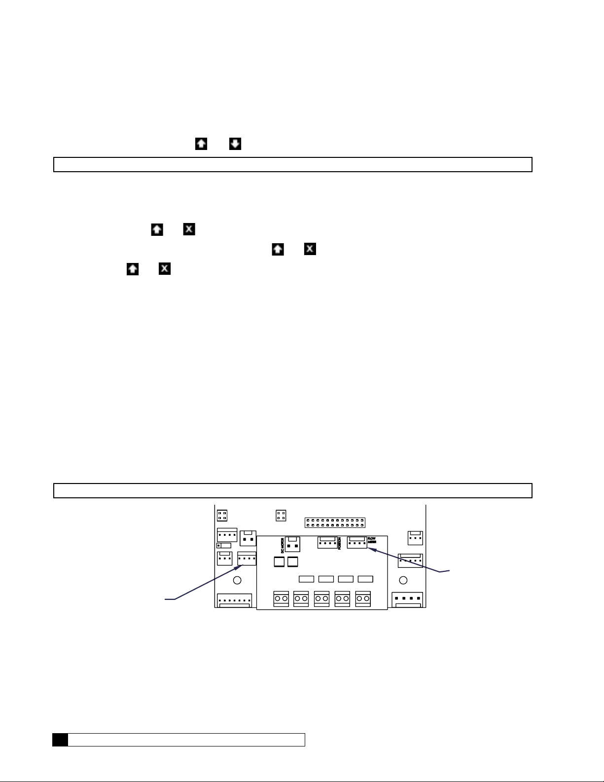
Flow Meters
There are two flow meters on the G1 RO system, the feed flow meter (FM1) and the product flow meter (FM2). Before
using the G1 RO it is necessary to first calibrate both flow meters. See Table 1.
Connect the wires of both flow meters to the CIB board using the 4 - pin connections provided. The feed flow meter connects to FM1 (J11) and the product flow meter connects to FM2 (J12). See Figure 17.
The pins are:
Pin 4 = not connected
Pin 3 = ground
Pin 2 = flow pulse signal
Pin 1 = 5 VDC power supply
NOTE Pin 1 on the GBE board is identified with a small WHITE dot.
J16
J17
J10
J1—PRODUCT
FLOW
J15—INLET FLOW
METER
The 4 - Pin Connections are:
NOTE: Pin 1 is identified with a small WHITE dot.
Figure 17. Flow Meter Connections on GBE Board
22 Culligan® Series G1 Reverse Osmosis
22 Cat. No. 01021713
METER

1. Start with both the recirc valve and the waste valves fully open (turn the valve all the way in a counter-clockwise
direction).
2. Start the RO.
3. When the pump turns on, slowly close the waste and recirc valves clockwise.
4. Try to close the waste valve until the flow rates to product and to drain are approximately even, then begin to
close the recirc valve, to bring the membrane feed pressure within the range of 80–120 psi.
5. Set the K-Factor for both FM1 and FM2 at the values listed in Table 1. See “G1 Tubing Configuration” on page
10.
6. On the GBE RO controller, select 3)INFORMATION and observe the FFLOW and PFLOW rates.
7. Using a stopwatch and a bucket, measure and record the time elapsed (in seconds) to fill a one-gallon bucket
with product water.
8. Meaure and record the time elapsed (in seconds) to fill a one-gallon bucket with waste water.
NOTE Convert your stopwatch readings to minutes (for gallons per minute) by dividing the number of sec-
onds by 60. For example, if you measure 45 seconds to fill a 1-gallon bucket, the fill time is 45/60 = 0.75
minutes, and the flow rate is 1/0.75 = 1.33 gpm.
Feed Flow Meter Product Flow Meter
Model FM1 Initial Nozzle Needed/K Factor FM2 Initial Nozzle Needed/K Factor
2S 500 500
3S 500 500
4S 500 500
2L 80 500
3L 80 500
4L 80 500
1F 80 80
2F 80 80
Table 1. K factor for FM1 and FM2.
9. Calculate the values for “A” and “B” using the following equations:
A =
(FM1 INITIAL) x (FFLOW DISPLAYED)
FFLOW ACTUAL
Where
FM1 INITIAL is from Table 1
FFLOW DISPLAYED
is displayed on the GBE RO controller
FFLOW ACTUAL = (Actual Product Flow) + (Actual Waste), in gallons per minute
(FM2 INITIAL) x (PFLOW DIS-
B =
PLAYED)
PFLOW ACTUAL
Where
FM2 INITIAL is from Table 1
PFLOW DISPLAYED is displayed on the GBE RO controller
PFLOW ACTUAL = (Actual Product), in gallons per minute
10. Use the directions in the next section to change the K factor for FM1 to the value for A, and then change the K
factor for FM2 to the value calculated for B.
11. Verify that the displayed values of FFLOW and PFLOW in the information screen on the GBE RO controller
match the actual measured flow rates from steps 7 and 8 while the RO is running.
Cat. No. 01021713
First Time Setup 23

RUNNING
JAN-01-12 12:01P
1) GO TO RUNNING
2) GO TO OFFLINE
3) INFORMATION
>4) SETUP
2) LANGUAGE
3) POWERON MODE
4) FLUSH MODES
>5) ACCESSORIES
1) WIRELESS REM
2) MODEM
>3) FLOW METERS
4) SWITCH INPTS
1. From the default home screen, press . The screen displays the main menu.
2. Press to scroll to 4) SETUP.
3. Press to select the SETUP menu.
4. Press to select 5)ACCESSORIES. The screen displays the accessories menu.
5. Press to select 3)FLOW METERS. The screen displays the flow meter
settings.
24 Culligan® Series G1 Reverse Osmosis
24 Cat. No. 01021713
Flow Meter Settings
Screen Display Range Changing the Setting
FLOW METERS
INSTALLED
Installed
Not Installed
The screen displays the installation status of the flow meter. Press
to change the state to installed if a flow meter is in-
stalled in the RO system.
FM1 K FACTOR
80.0
0–9999
Press
calculated value for the flow meter FM1 and/or FM2.
or and then to change the K-Factor to the
RUNNING
JAN-01-12 12:01P
6. Press to save the settings and return to the home screen.
12. Once all the desired flows are set, allow the system to run for approximately 30 minutes, and then record the
following measurements using the units gauges (U), GROC information screens (G), and your instruments (I):
a. Feed Flow Rate, gpm (G)
b. Feed Water Temperature, °F (I)
c. Feed Water SDI (I)
d. Feed TDS, ppm (I)
e. Inlet Pressure, psig (U)
f. System (pump outlet) pressure, psig (U)
g. Product TDS, ppm (G)
h. Product Flow, gpm (G) x TCF
i. Product Temperature, °F (G)
j. Product Pressure, psig (I)
k. Concentrate (waste) flow, gpm (a–h)
l. % Recovery (see page 121)
m. % Rejection (see page 121)
1
TCF = Temperature Correction Factor. Refer to Table 2 on page 26 for this value.
1
=
NOTICE The Global RO Controller has a feature which records historical data. The intial startup data is kept
in the controllers memory. It is still a good idea to record the values on a separate sheet of paper
and keep the data near the unit in case of electrical problems.
13. Choose GO TO OFFLINE from the main menu. Connect the product tubing to the service plumbing.
14. Test the operation of the pressure switch by closing the inlet water supply valve. The unit should shut off immediately.
CAUTION! If the unit does not shut off, turn the unit OFF immediately to prevent pump damage.
Disconnect electrical power source, then check the wiring and replace the switch, if
necessary.
15. Open the inlet water supply valve. The unit should restart.
16. If connected, test the storage tank level control shutdown and the pretreatment lockout function.
Cat. No. 01021713
First Time Setup 25
Normal Operation
During normal operation, the system usually will start up and shut down based on signals from a level control or pressure
switch. Adjust the feed pressure as required (no higher than 150 psig) to maintain a constant product flow. Record the
performance data regularly and compare it to the performance on initial start up. If any changes are noticed, the product
flow should be normalized to determine if cleaning is required (see Product Flow Calculations below).
Product Flow Calculations
The product flow rate depends primarily on feed water pressure, product water pressure, and temperature. All 1-Series
RO water conditioners have specified nominal flow rates based on approximately 105 psig net pressure and 77°F temperature. However, in most applications the temperature and pressure are lower, so the product flow rate is lower than the
nominal flow rate. The actual flow rate must be converted to flow under standard conditions, then compared to the initial
performance (also converted to standard conditions) to determine whether the system is still working properly.
To convert the data to standard conditions,
1. Measure the product flow. Example: 1000 ml/min
2. Measure the feed pressure. Example: 120 psig
3. Measure the product pressure. Example: 5 psig
4. Subtract the product pressure from the feed pressure. Example: 115 psig
5. Divide the product flow by the result from step 4. Example: 1000 ÷ 115 = 8.69 ml/min/psi
6. Multiply the result from step 5 by 105. Example: 8.69 x 105 = 913 ml/min
7. Measure the temperature of the feed water, then determine the temperature correction factor from Table 2.
Example: At a temperature of 55°F , the factor is 1.54.
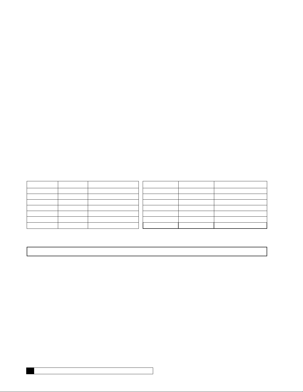
Temp. °F Temp. °C Correction Factor Temp. °F Temp. °C Correction Factor
40 4.4 2.12 75 24 1.04
45 6.7 1.90 80 27 0.95
50 10 1.71 85 29 0.86
55 13 1.54 90 32 0.79
60 16 1.39 95 35 0.72
65 18 1.26 100 38 0.66
70 21 1.14
Table 2. Temperature Correction Factors
8. Multiply the result of step 6 by the temperature correction factor. Example: 913 ml/min x 1.54 = 1406 ml/min.
NOTICE To convert ml/min to gallons per day, multiply by 0.38. For example, 1406 ml/min x 0.38 = 534 gpd.
9. Compare the current standardized flow to the initial standardized flow. If the flow has decreased by 15% or
more, it is time to clean the elements.
Example: If the initial standardized flow was 570 gpd, and the current standardized flow is 470 gpd, the flow has
decreased by 100 gpd, or 18% (100/570) = 0.18. The elements should be cleaned.
10. If the problem cannot be corrected with the troubleshooting guide and assistance is required, please have the
following information available when calling the Culligan dealer:
• Product flow rate
• Concentrate flow rate
• Feed pressure
• Product water quality
• Feed water quality
• Feed water temperature
• Prefilter outlet (and inlet if the optional prefilter inlet gauge was installed)
• Product pressure
26 Culligan® Series G1 Reverse Osmosis
26 Cat. No. 01021713

Switch Inputs
Several switch types may be installed in an RO system, including
• Low Pressure Switch
• Pretreatment Lockout Switch
• Float (Level Control) Switch
See “GBE RO Controller Wiring” on page 102 for a diagram of all three switches.
Low Pressure Switch
The GBE RO Controller is equipped with a low pressure switch to protect the pump from starvation/cavitation. If the inlet
pressure switch goes LOW and stays there for at least XX seconds (set at setup/accessories/switch inputs), the pump will
turn off. For a positive displacement pump, XX should be specified at 1–5 seconds. The controller keeps track of how many
times this happens: if fewer than five times since the most recent of either midnight or the last time the operator manually selected GO TO RUNNING from the main menu, then the system will attempt to restart. If this is the fifth time it has happened,
then the system goes to OFFLINE and throws the LOW INLET PRESSURE error condition.
NOTE This five-time counter on the number of restarts allowed resets to zero every night at midnight and
every time that the operator selects YES from the Main Menu/Go to Running screen.
The pressure switch is prewired at the factory to the GBE RO controller AUX board POSITION (J1) pins utilizing pins 2
and 4. The switch is factory set to 18 psi. The pressure can be adjusted from 6 psi to 30 psi by turning the knurled ring on
the body of switch clockwise to increase the pressure and counter-clockwise to decrease. One revolution is approximately
6.5 psi.
Pretreatment Lockout
The GBE RO controller allows an external contact closure to cause the RO to go into a “pre-treat lockout” condition. If the
GBE RO controller state was in any state other than OFFLINE, the state will change to STANDBY as soon as the pretreat
lockout is engaged. When pretreat lockout is disengaged, the system will either move to STARTING or stay in STANDBY
based upon the status of the float switches and the settings specified at main menu/ setup/ accessories/ switch inputs.
The pretreat lockout can be engaged by either a normally open or normally closed input signal to the pretreat lockout
terminals from the main menu/setup/accessories/switched inputs menus. The factory default is that CLOSED will specify
pretreat lockout.
Note that the pre-treat lockout input switch must move to, and stay in its new position for a continuous period of at least
two (2) seconds for the pretreat lockout to be triggered
®
Timeclock controlled softeners, such as the Hi-Flo
treatment, they should be duplexed, or regenerated by a timeclock so that regeneration can occur when the unit is not in
operation.
3, do not offer pretreatment lockout. If these units are used for pre-
Cat. No. 01021713
First Time Setup 27

Wiring for Softeners and Filters with MVP Controller
For these systems, you must add a 24V relay P/N 01016156, to provide the pretreatment contact.
MVP to Relay: Connect a wire from Terminal 5 of the relay to the left terminal of P8 (Aux 2) on the MVP circuit board.
Connect another wire from terminal 1 of the relay to the right terminal of P8. Refer to Figure 18.
Relay to GBE RO controller: Connect a wire from the POSITION (J2), PIN 3 terminal on the AUX board to terminal 3 on
the relay. Connect another wire from the POSITION (J2), PIN 4 terminal on the AUX board to terminal 4 on the relay.
LCD
SW6 Dip Switch
P11
Battery
P6
Motor
P9 Power
2.5VAC 24V
MVP
P5
Aux1
P7 Sol
Valve
P8
Aux2
P1
Cam
Aqua
Sensor
Flow
Meter
Relay
P3
Comm
GROC BOARD
Figure 18. MVP to GBE RO controller relays.
28 Culligan® Series G1 Reverse Osmosis
28 Cat. No. 01021713

Wiring for Softeners and Filters with GBE RO Controller
For these systems, you must add a 24 VAC relay, part number 01016156, to provide the pretreatment contact.
GBE to Relay: Connect a wire from terminal 5 of the relay to the left terminal of Aux 4 on the GBE softener/filter circuit
board. Connect another wire from terminal 1 of the relay to the right terminal of Aux 4. Refer to Figure 19.
Relay to GBE RO controller: Connect a wire from the POSITION (J2), PIN 3 terminal on the AUX board to terminal 3 on
the relay. Connect another wire from the POSITION (J2), PIN 4 terminal on the AUX board to terminal 4 on the relay. Use
the GBE RO controller Aux cable kit, P/N 01021830, to connect cables to the GBE RO controller board.
J5 J6
J7
GBE SOFTENER/FILTER
J16
AUX OUT 4
J17
J10
J2
Relay
GROC BOARD
Cat. No. 01021713
Figure 19. GBE to GBE RO controller relays.
First Time Setup 29

Float Level Control
P/N: XXXXXXXX rev. X
VENDOR: XXXXXX
DATE CODE: WK/YY
HEX FILE: XXXXXXXX rev. X
Remote Display
RF Board Connector
Modem
Connectors
Product Flow Meter (J1)
The GBE RO controller provides a Level Control High switch as well as a Level Control Low switch. You can use the Level
Control High switch alone, or with the Level Control Low switch.
The Level Control connections are located on the GBE RO controller board. They are labeled POSITION (J12) on the
main GBE RO controller board. Pin 4 is common and Pin 2 is for HIGH level and Pin 3 is for LOW level.
These switches can be specified to be either “OPEN WHEN LEVEL IS ABOVE SWITCH” or “CLOSED WHEN LEVEL IS
ABOVE SWITCH” when the level of water is above the switches. Both switches must have the same OPEN or CLOSED
specification. For example, you can specify (main menu/setup/accessories/switch inputs) that the float switches will be
CLOSED when the level of water is above the level of the switches. The system assumes that a float switch is “off” when
the water is below the switch and it is on when the state of the switch matches to user specified OPEN or CLOSED condition. Use the GBE RO controller switch accessory kit (P/N 01022360) to connect Float Switch and Pretreatment Lockout
to the controller board. The kit contains four connectors (P/N 01021838) with wire leads. See page 102 for wiring information.
Float Switch (J12)
Plug into J12
and Pretreat Lockout
Connectors for Float Switch
Figure 21. J12 float switch.
Figure 20. GROC plug-on connector with wire leads.
4 3 2 1
Storage Tank Setup When Using Both a High and Low Level Float Switch (Two Floats)
When two floats are used, the behavior of the controller is such that it will switch from RUNNING to STANDBY when the
water reaches the upper float switch and it changes state from being off to on. The system will stay in STANDBY until the
LOWER float switch transitions from on to off. When this LOWER switch transitions from on to off, the system will switch
back into RUNNING unless it is also in Pretreat Lockout at this point in which case it will transition to RUNNING when the
Pretreat Lockout disengages.
In order for the system to operate correctly using two float switches, it is necessary to specify a value of 0 (zero) as the Hi
Float Restart Delay time (main menu/steup/accessories/switch inputs).
Storage Tank Setup When Using a Single High Level Float Switch
Connect the level control to the FLTHI terminals. The system will switch from RUNNING to STANDBY when the water
reaches the upper float switch and it changes state from being off to on. The system will transition back to RUNNING a
specified number of minutes after the upper float switch transitions from on back to off. The specified number of minutes
to delay must be greater than 0 (zero). If it is specified as zero, then the system will operate as described in the previous
paragraph for two-float switches. The delay can be specified in whole minutes up to a maximum of 999 minutes. Note that
it is necessary to select this delay carefully, based upon the size of the storage tank and the maximum rate of draw-down
on the storage tank in comparison to the maximum rate of producing RO water or it is possible that the storage tank could
run dry.
NOTICE Do not apply power to these terminals. Use dry contacts only.
30 Culligan® Series G1 Reverse Osmosis
30 Cat. No. 01021713

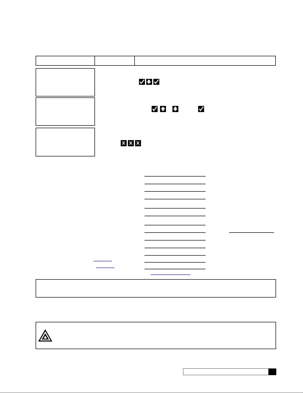
Basic Operation
After the first-time setup has been completed, the RO system will be online (RUNNING) or offline (OFFLINE). You can
change the operation status of the system from the main menu on the Global RO Controller.
RUNNING
JAN-01-12 12:01A
Go To Running
>1)GO TO RUNNING
2)GO TO OFFLINE
3)INFORMATION
4)SETUP
1. This is the home screen. Press any button except to display the main menu.
2. Press to select 1)GO TO RUNNING.
GO TO RUNNING
NO
STARTING
JAN-01-12 12:01P
STARTUP FLUSH
RUNNING
JAN-01-12 12:01A
Go To Offline
1)GO TO RUNNING
>2)GO TO OFFLINE
3)INFORMATION
4)SETUP
GO TO OFFLINE
NO
3. The GROC screen displays the GO TO RUNNING command. Press or
and then
(select NO to cancel the command and return to the main menu).
4. The screen displays the status of the unit as it initiates the startup process.
5. The home screen displays the operational status (RUNNING).
1. Press to select 1)GO TO OFFLINE.
2. The GROC screen displays the GO TO OFFLINE command. Press or
and then
(select NO to cancel the command and return to the main menu).
to change the value to YES if you want the system to start running
to change the value to YES if you want the system to stop running
OFFLINE
JAN-01-12 12:01A
Cat. No. 01021713
3. The screen displays the main menu. Press repeatedly to return to the home
screen, which displays the operational status (OFFLINE).
Basic Operation 31

Setup
After completing the first time setup for the RO, you must also complete the system setup for flush modes, accessories,
and error limits before completing the initial startup.
Flow Meter K-Factor setting is required during setup. All other RO settings are optional depending on the accessories
installed. The RO controller does not require any specific setup to run unless accessories are installed or will be installed.
RO accessories include:
Accessory Global RO Controller (GROC) Setting
Flush Valves Setup—>Flush Modes
Flow Meters Setup—>Accessories—>Flow Meters
Modem Setup—>Accessories—>Modem
Wireless Remote, RF Board Setup—>Accessories—>Wireless Rem—>Channel #
Level Controls Setup—>Accessories—>Switch Inputs
Repressurization System Setup—>Accessories—>Switch Inputs
Pretreatment Lockout Setup—>Accessories—>Switch Inputs
Pressure Transducers (G2, G3 only) Setup—>Accessories—>Press Gauges
System Setup
Set Up Time/Date
If the unit loses time for some reason, you can use this setting to reset the correct date and time. Please note that if you
have a modem installed and connected to the phone line, the unit will check for the correct time each time it calls in.
RUNNING
JAN-01-12 12:01P
1. From the default home screen, press . The screen displays the main menu.
1) GO TO RUNNING
2) GO TO OFFLINE
3) INFORMATION
>4) SETUP
2. Press to scroll to 4) SETUP.
3. Press to select the SETUP menu.
>1) TIME/DATE
2) LANGUAGE
3) POWERON MODE
4. Set Time/Date is the first menu item, so press to select 1) SET TIME/DATE.
The screen displays the first setting that can be changed.
4) FLUSH MODES
Time/Date Settings
Screen Display Range Procedure
SET
MONTH JAN
Jan–Dec
1. The screen displays the month setting. Press
and then
to change the value and see the next setting.
or
SET
DAY 1
32 Culligan® Series G1 Reverse Osmosis
1–31
2. The screen displays the day setting. Press
then
to change the value and see the next setting.
32 Cat. No. 01021713
or and

Screen Display Range Procedure
SET YEAR
2012
CLOCK TYPE
12 HR
SET HOUR
12PM
2010–2040
12 or 24
12AM–11PM
3. The screen displays the year setting. Press
then
4. The screen displays the clock type setting. Press
5. The screen displays the hour setting. Press
then
to change the value and see the next setting.
and then to change the value and see the next setting.
to change the value and see the next setting.
or and
or
or and
SET
MINUTES 25
DAYLIGHT SAVING
YES
0–59
YES
NO
6. The screen displays the minutes setting. Press
and then
7. The screen displays whether you observe daylight savings
time where the RO unit is installed. Press
then
menu.
to change the value and see the next setting.
or and
to change the value and return to the Time/Date
RUNNING
JAN-01-12 12:01P
8. Press to return to the home screen.
Set Up Language
Use the language setting to change the displayed language on the RO controller.
NOTE Ensure the units of measure (US, Metric) are appropriate. See page 21 to change if necessary.
RUNNING
JAN-01-12 12:01P
1. From the default home screen, press . The screen displays the main menu.
or
1) GO TO RUNNING
2) GO TO OFFLINE
3) INFORMATION
>4) SETUP
1) TIME/DATE
>2) LANGUAGE
3) POWERON MODE
4) FLUSH MODES
Cat. No. 01021713
2. Press to scroll to 4) SETUP.
3. Press to select the SETUP menu.
4. Press to select 2)LANGUAGE. The screen displays the last selected lan-
guage of the RO controller.
Setup 33

LANGUAGE
ENGLISH
1) HEURE/DATE
>2) LANGUE
3) EN MARCHE
4) MODES FLUSH
Set Up Power On Mode
RUNNING
JAN-01-12 12:01P
1) GO TO RUNNING
2) GO TO OFFLINE
3) INFORMATION
>4) SETUP
1) TIME/DATE
2) LANGUAGE
>3) POWERON MODE
4) FLUSH MODES
5. Press or and then to change the display to your preferred
language.
6. The screen displays the setup menu in the selected language of the RO controller.
1. From the default home screen, press . The screen displays the main menu.
2. Press to scroll to 4) SETUP.
3. Press to select the SETUP menu.
4. Set Time/Date is the first menu item, so press to select 3)POWERON
MODE.
POWERON MODE
5. Press or and then to select Power On Mode options.
OFFLINE
RUNNING
OFFLINE
RUNNING
JAN-01-12 12:01P
6. Press to return to the home screen.
The RO system will start whenever power is supplied.
The RO system will go into standby when power is supplied to the unit.
Flush Modes
The GBE RO controller can be programmed to operate up to six different flush modes. Multiple flush modes can be specified and operating at any one time. If any one or more flush modes are calling for flushing to happen at a certain time, the
flush will take place. Some flush modes require additional plumbing and components such as solenoid valves.
Startup Flush
In this mode the fast flush solenoid (SV-2) opens for a specified number of minutes each time that the pump turns on.
Standby Flush
In this mode any time that the system state is in STANDBY, the inlet AND fast flush solenoids open for a specified number of
minutes every specified number of hours. This is a line-pressure-level flush (ie the pump does NOT turn on during this flush).
34 Culligan® Series G1 Reverse Osmosis
34 Cat. No. 01021713

Time Trigger Flush
'UDLQ
3XPS
In this mode, any time that the system state is in RUNNING, the fast flush solenoid (SV-2) will open for a specified number
of minutes every specified number of hours. Note that the pump is ON during this flush.
Flow Trigger Flush
In this mode, any time that the system state is in RUNNING, the fast flush solenoid (SV-2) will open for a specified number
of minutes every specified number of PRODUCT RO water generated. Note that the pump is ON during this flush.
Quality Flush
If this mode is enabled, the product diversion solenoid (SV-3, NOT INCLUDED) is opened as soon as the pump turns on
when the RO system is RUNNING. This solenoid will remain open until the measured product TDS drops below the specified quality flush TDS setpoint or until the quality flush time period expires. If the TDS does not drop below the setpoint
during this period, the unit will switch to OFFLINE and the “product TDS High” error will be thrown. The Quality Flush solenoid valve is wired to the AUX board on the GBE RO controller at terminal AUX4. The solenoid valve must be 24 VAC.
7'6
7R 6HUYLFH
69
,QOHW
9DOYH
3XPS
0(0%5$1( +286,1*6
Figure 22. RO quality flush.
69
At startup, SV1 opens, and then the pump turns on. SV3 opens while the system monitors the product TDS level. The
user programs the maximum allowable product TDS and the number of minutes allowed following startup to reach the allowable TDS level. Usually at startup, the TDS level starts high and then drops. If the level drops below the allowable level
within the allowed time, then SV3 will close, and the unit is now in service. If the allowable TDS level cannot be reached,
the unit will shut down and generate an error message.
Permeate Flush
If this mode is enabled, the permeate flush solenoid (SV-3, NOT INCLUDED) is opened as soon as the pump turns off.
This solenoid will remain open until the permeate flush time period expires and permits water from an optional permeate
storage tank to flush the membranes. The Permeate Flush solenoid valve is wired to the AUX board on the GBE RO controller at terminal AUX4 (G1). The solenoid valve must be 24 Volt.
&KHFN
9DOYH
69
36
)(('
69
&KHFN
9DOYH
69
'UDLQ
Cat. No. 01021713
Figure 23. RO permeate flush.
Setup 35

At shutdown, the pump turns off and SV1 closes. Then fast flush solenoid valve SV2 and permeate valve SV3 open for a
programmed number of minutes. During this time, RO product water stored either in an elevated atmospheric tank or in a
pressurized storage tank floods through the pump and the feed side of the membrane, and then SV2 and SV3 close. This
process provides RO-quality water during shutdown on both sides of the membrane to keep the membrane clean. This
process also ensures that the RO will provide high quality product water the next time the pump is turned on.
NOTE Quality Flush and Permeate Flush are mutually exclusive optional features.
Flush Mode RO Pump Inlet Valve Waste (Fast) Flush Valve Product Flush Valve
Start Up On Open Open Closed
Standby Off Open Open Closed
Time On Open Open Closed
Flow On Open Open Closed
Quality On Open Closed Open
Permeate Off Closed Open Open
Table 3. RO pump and valve states during flush modes.
Any time that a Flush is actually taking place while the system state is RUNNING, the system will ignore the following error limits: delivered product TDS high, %recovery low, %recovery high, %reject low, membrane pressure drop, pump feed
pressure low. Once the flush ends, the error checking will resume. If the inlet pressure switch reports LOW pressure for
at least XX (XX is programmable at 1-30 seconds, at the main menu/setup/accessories/switch inputs menu) continuous
seconds, even if this is during or even partially during a flush time, the system will still recognize this instance as an error
condition, and it will begin the LOW PRESSURE process.
Flush Mode Setup
RUNNING
JAN-01-12 12:01P
1) GO TO RUNNING
2) GO TO OFFLINE
3) INFORMATION
>4) SETUP
1) TIME/DATE
2) LANGUAGE
3) POWERON MODE
>4) FLUSH MODES
1. From the default home screen, press . The screen displays the main menu.
2. Press to scroll to 4) SETUP.
3. Press to select the SETUP menu.
4. Set Time/Date is the first menu item, so press to select 4)FLUSH
MODES.
36 Culligan® Series G1 Reverse Osmosis
36 Cat. No. 01021713

Flush Mode Settings
Screen Display Range Procedure
>1) STARTUP
2) STANDBY
3) TIME TRIGGER
4) FLOW TRIGGER
START UP MODE
OFF
FLUSH DURATION
3
MINUTES
STANDBY MODE
OFF
FLUSH DURATION
3
MINUTES
Startup
Standby
Time Trigger
Flow Trigger
Qual Flush
Perm Flush
Off
On
1–180
Off
On
1–180
5. The screen displays the Flush Modes menu. Press
to scroll through the menu and then
setting.
6. The screen displays the Start Up Mode setting. This will flush
the drain prior to starting the pump. Press
then
sure flush.
7. If startup mode is set to ON, the screen displays the flush
duration of the drain. Press
change the value and then return to the Flush Mode menu.
8. The screen displays the Standby Mode setting. This will flush
the drain when the unit is in standby mode. Standby mode
may be triggered manually, by a STORAGE TANK FULL error, by a pretreatment lockout command, or other states. This
is a low pressure flush. Press
change the value if necessary.
9. If standby mode is set to ON, the screen displays the flush du-
ration setting. Press
value and then display the next setting.
to change the value if necessary. This is a line pres-
or and then to
or and then to change the
to select a flush mode
or and
or and then to
or
FLUSH EVERY
3
HOURS
TIME TRIG MODE
OFF
FLUSH DURATION
3
MINUTES
FLUSH EVERY
4
HOURS
Cat. No. 01021713
1–24
Off
On
1–180
1–24
10. If standby mode is set to ON, the screen displays the flush in-
terval setting. Press
value and then return to the Flush Mode menu.
11. The screen displays the Time Trigger Mode setting. A flush
will be triggered after a specified amount of time has passed.
Press
necessary.
12. If time trigger mode is set to ON, the screen displays the flush
duration setting. Press
the value and then display the next setting.
13. If time trigger mode is set to ON, the screen displays the flush
interval setting. Press
the value and then return to the Flush Mode menu.
or and then to change the value if
or and then to change the
or and then to change
or and then to change
Setup 37

Screen Display Range Procedure
FLOW TRIG MODE
OFF
FLOW TRIG MODE
OFF
FLUSH DURATION
3
MINUTES
FLUSH EVERY
100
GALLONS
QUAL FLUSH MODE
DISABLE
Off
On
Off
On
1–180
100–1000
Disable
14. The screen displays the Flow Trigger Mode setting. Press
or and then to change the value and see the flow
trigger mode settings.
15. The screen displays the Flow Trigger Mode setting. If the system is running, the unit will flush after generating a specified
amount of reverse osmosis water. Press
then
16. If flow trigger mode is set to ON, the screen displays the flush
duration setting. Press
the value and then display the next setting.
17. If flow trigger mode is set to ON, the screen displays the flush
interval setting. Press
the value and then return to the Flush Mode menu.
18. The screen displays the Quality Flush Mode setting. When the
system is running, the system sends all water to drain until a
preset quality is reached, at which time the water will flow to
the product outlet. This is a high pressure flush (pump is on).
The quality flush mode is disabled and can not be changed.
Press any button to return to the Flush Mode menu.
to change the value if necessary.
or and then to change
or and then to change
or and
PERM FLUSH
OFF
FLUSH DURATION
10
SECONDS
RUNNING
JAN-01-12 12:01P
38 Culligan® Series G1 Reverse Osmosis
1–180
21. Press to return to the home screen.
Off
On
19. The screen displays the Permeate Flush setting. This flush
requires an optional solenoid valve and permeate storage tank
from where the flush water is drawn. Press
then
20. If permeate flush mode is set to ON, the screen displays the
flush duration setting. Press
change the value and then display the next setting.
to change the value if necessary.
or and then to
38 Cat. No. 01021713
or and

Switch Inputs Programming
RUNNING
JAN-01-12 12:01P
1) GO TO RUNNING
2) GO TO OFFLINE
3) INFORMATION
>4) SETUP
2) LANGUAGE
3) POWERON MODE
4) FLUSH MODES
>5) ACCESSORIES
1) WIRELESS REM
2) MODEM
3) FLOW METERS
>4) SWITCH INPTS
Switch Inputs Settings
Screen Display Range Changing the Setting
1. From the default home screen, press . The screen displays the main menu.
2. Press to scroll to 4) SETUP.
3. Press to select the SETUP menu.
4. Press to select 5)ACCESSORIES. The screen displays the accessories menu.
5. Press to select 4)SWITCH INPTS. The screen displays the switch
inputs settings.
PRESSURE SWITCH
NORMALLY OPEN
PS Sw
Delay: 5
SECONDS
SV1 Delay:
10
SECONDS
PRETREAT SWITCH
NORMALLY OPEN
FLOAT SWITCHES
NORMALLY OPEN
Normally Open
Normally Closed
0–9,#
each digit
0–300
Normally Open
Normally Closed
Normally Open
Normally Closed
Used with the inlet pressure switch. Standard pressure switch is
normally open. Press
state if necessary.
Sets the pressure switch delay time. This is the number of seconds
the low pressure must exist before activating the switch. Press
or and then to change.
The number of seconds elapsed from the inlet solenoid valve (SV-
1) opening until the motor starts. Press
to change.
Used with the inlet pressure switch. Standard pressure switch is
normally open. Press
state if necessary.
Used to set whether float switches (level control) are normally
open or closed. There are two float switch contacts; they both must
be normally open or closed. Press
change the state if necessary.
or and then to change the
or and then
or and then to change the
or and then to
Cat. No. 01021713
Setup 39

Screen Display Range Changing the Setting
FS Hi
Delay: 0
MINUTES
RUNNING
JAN-01-12 12:01P
Used only when using the float switch high contacts. This sets how
0–120
6. Press to save the settings and return to the home screen.
long the float switch stays closed after transitioning from high to
low level.
40 Culligan® Series G1 Reverse Osmosis
40 Cat. No. 01021713

Accessories
5 3/8”
There are several components of the G1 RO that can be configured from the Accessories manu, including:
• Wireless Remote
• Modem
• Flow Meter
• Pressure and Level Control Switches
• Pressure Gauges
• Total Dissoved Solids Probes
• Error or Status Monitor
• SV3 or Target TDS Monitor
Wireless Remote
1. Select a location for the wireless remote monitor (Figure 24). The location must be near an electrical outlet. If a
modem is used in the remote, then the location should also be near a standard RJ-11 type telephone wall jack.
MODEM CONNECTION
SCREWS
Figure 24. Wireless remote monitor.
CAUTION! Do not touch any surfaces of the circuit board. Electrical static discharges may cause
damage to the board. Handle the circuit board by holding only the edges of the circuit
board. Keep replacement boards in their special anti-static bags until ready for use.
Mishandling of the circuit board will void the warranty.
2. Use the Hole Drilling Template as a guide to drilling two holes to mount the remote monitor. If drilling into wall
board, drill two 5/16” diameter holes and insert the plastic drywall anchors into the holes securing them with the
two #10 screws provided. If drilling into a solid surface, drill two 7/32” holes into the surface and screw the two
#10 screws into the holes. In either case, leave a gap of approximately 3/32” between the head of the screw
and the wall.
3. (Optional) If a modem is to be installed into the remote monitor, refer to page 46 for installation and setup.
4. Connect the power cord to the bottom of the remote monitor. If a modem is to be used in the remote, plug a
standard telephone extension cord into the bottom of the remote monitor.
5. Hang the remote monitor on the two screws. Plug into 120V outlet.
6. Disconnect power to the RO unit. Open the control.
POWER CONNECTION
Cat. No. 01021713
Accessories 41

Figure 25. RF board location on GROC board.
7. Install RF board into unit controller. Line up pins in RF board and press firmly into black connectors. Note orientation of RF board (see Figure 25). Make sure the RF board is fully seated into all of the socket. Reconnect
power.
8. Follow the directions on the next page to program BOTH the main and remote monitor units to communicate
with each other. If modem has been installed in the remote, it is also necessary to follow the directions in the
next section of this manual to configure the main controller to use the modem in the remote.
Wireless Remote Setup
Begin the wireless setup using the wireless remote device.
RUNNING
JAN-01-12 12:01P
1) INFORMATION
>2) SETUP
3) DIAGNOSTICS
>1) RF SETUP
2) MODEM SETUP
1. From the default home screen, press . The screen displays the main menu.
2. Press to select 2)SETUP.
3. Press to select 1)RF SETUP.
Wireless Remote Settings
Screen Display Range Changing the Setting
CHANNEL #
1
RF FREQUENCY
915 Mhz
RUNNING
JAN-01-12 12:01P
42 Culligan® Series G1 Reverse Osmosis
1–254
433, 869,
or 915
4. Press to save the settings and return to the home screen.
Press
valve. The CHANNEL # for the RO controller must be the same as the CHANNEL # for the Remote Display.
Use this setting to select the correct radio frequency. Do not change the RF frequency for North America installations.
or and then to select the channel number of the control
42 Cat. No. 01021713

GBE-Wireless Communication Setup
Now set up the RO controller to communicate with the wireless remote.
RUNNING
JAN-01-12 12:01P
1) GO TO RUNNING
2) GO TO OFFLINE
3) INFORMATION
>4) SETUP
2) LANGUAGE
3) POWERON MODE
4) FLUSH MODES
>5) ACCESSORIES
>1) WIRELESS REM
2) MODEM
3) FLOW METERS
4) SWITCH INPTS
REMOTE DISPLAY
NOT INSTALLED
1. From the default home screen, press . The screen displays the main menu.
2. Press to scroll to 4) SETUP.
3. Press
4. Press to select 5)ACCESSORIES. The screen displays the accessories menu.
5. Press to select 5)ACCESSORIES. The screen displays the accessories menu.
6. Press or and then to change the state to INSTALLED.
to select the SETUP menu.
CHANNEL #
>1
RF FREQUENCY
915 Mhz
RUNNING
JAN-01-12 12:01P
7. Press or and then to select the channel number of the control valve.
The CHANNEL # for the RO controller must be the same as the CHANNEL # for
the Remote Display.
8. Use this setting to select the correct radio frequency. Do not change the RF frequency for North America installations..
9. Press to save the settings and return to the home screen.
Cat. No. 01021713
Accessories 43

Check Signal Strength Between the GBE RO Controller and Remote
Check the signal strength once the RO controller and wireless remote are set up.
RUNNING
JAN-01-12 12:01P
1) GO TO RUNNING
2) GO TO OFFLINE
3) INFORMATION
>4) SETUP
3) POWERON MODE
4) FLUSH MODES
5) ACCESSORIES
>6)DIAGNOSTICS
>1) TST WIRELESS
2) TESTPHONELIN
3) USE DATA PORT
4) TEST APP
1. From the default home screen, press . The screen displays the main menu.
2. Press to scroll to 4) SETUP.
3. Press to select the SETUP menu.
4. Press to select 6)DIAGNOSTICS.
5. Press to select 1)TST WIRELESS. The screen displays the wireless test
screen.
WIRELESS TEST
0 / 188
RSSI=5
RUNNING
JAN-01-12 12:01P
6. The screen displays the test number and total number of attempts and the received signal strength indicator (RSSI). The system will continue to test the signal
strength until you press any button to return to the diagnostics menu.
The signal strength indicator (RSSI) will show a value of between 0 and 8. If the
RSSI is at least 4, then the installation is complete. It the SSI drops below 4, then
it may be necessary to select an alternate location for the wireless remote.
7. Press to save the settings and return to the home screen.
44 Culligan® Series G1 Reverse Osmosis
44 Cat. No. 01021713

Modem
NOTE The modem can be installed into either the back of the RO controller or the back of the remote control
board. The functionality of the modem is the same in either installation.
NOTE Use of the modem kit requires a one-year subscription to either a Level 1 or Level 2 Telecom package.
Self-service registration is available at www.myculligan.com.
1. Before installing the modem into the back of the RO Controller board or the back of the remote, the RO
Controller circuit board or the remote must first be powered off.
2. When handling all circuit boards, take care to only touch the edges of the circuit boards—not the metal pins.
The electronics on all circuit boards can be damaged by static electricity.
3. Make sure all of the pins at all four connectors are aligned between the modem board and the main controller
board. Make sure that the modem board is fully seated into all four sockets.
4. When all connections have been made restore power.
5. Connect the modem to the telephone line by plugging a standard RJ-11 phone extension cord into the modem
board.
NOTE The GBE RO Controller is designed to plug into an analog telephone line (standard residential phone
line). This includes phone lines connected to most residential VoIP (voice over Internet) phone systems and to residential DSL phone systems. If you are connecting the RO to a DSL phone system,
follow the DSL provider recommended method to connect standard phones to the DSL service. Many
systems recommend or require the use of DSL line filters between the phone jack and the device.
NOTE Try to place the RO Controller or Remote Display near a telephone jack. A splitter might be needed if
the jack is already in use.
Installing the Modem on the GBE RO Controller Board
Open the controller cover and locate the modem connection on the back of the board (see Figure 26). Insert line modem
board (part number 01020307) into the socket on the back of the board. Make sure that all of the pins in all four connectors are aligned and make sure the modem is fully seated into all of the sockets.
Cat. No. 01021713
Figure 26. Back of GROC board.
Accessories 45

Installing the Modem In the Remote
Open the remote monitor housing by removing the two screws and squeezing the sides of the monitor housing slightly.
Insert the modem board (P/N 01020307) into the socket on the back of the remote board (see Figure 27). Make sure that
all of the pins in all four connectors are aligned and make sure the modem is fully seated into all of the sockets. Snap the
two halves of the remote housing back together using light finger pressure and insert the two screws.
Figure 27. Modem installed on back of remote board.
GBE RO Controller Modem Setup
RUNNING
JAN-01-12 12:01P
1) GO TO RUNNING
2) GO TO OFFLINE
3) INFORMATION
>4) SETUP
2) LANGUAGE
3) POWERON MODE
4) FLUSH MODES
>5) ACCESSORIES
1) WIRELESS REM
>2) MODEM
3) FLOW METERS
4) SWITCH INPTS
1. From the default home screen, press . The screen displays the main menu.
2. Press to scroll to 4) SETUP.
3. Press
4. Press to select 5)ACCESSORIES. The screen displays the accessories menu.
5. Press to select 2)MODEM. The screen displays the modem settings.
to select the SETUP menu.
46 Culligan® Series G1 Reverse Osmosis
46 Cat. No. 01021713

GROC Modem Settings
Screen Display Range Changing the Setting
TELEPHONE MODEM
INSTALLED
MODEM CONNECTION
LANDLINE
MODEM LOCATION
IN MAIN CONTROL
TIME ZONE GMT
+00:00
Installed,
Not
Installed
LandLine
CellModem
In Main
Control
In Remote
0 to +12 or
-12
Press
is installed inside the Smart Controller.
Press
See the note on the previous page about analog and digital phone lines.
Press
Change this setting only if a modem is installed.
Press
location with respect to Greenwich Mean Time (GMT).
When using a modem, the controller will occasionally access the Internet to
synchronize the date and time. In order to do this correctly, the control must
be told which time zone it is installed in. The time zone is specified as so many
hours ahead or behind GMT time. The GMT offset for some common cities is
listed below:
or and then to select INSTALLED if a telephone modem
or and then to change the Modem connection setting.
or and then to change the Modem Location setting.
or and then to specify the time zone of the RO Controller
GMT Offset
New York -5:00 (and anywhere in EST)
Chicago -6:00 (CST)
Denver -7:00 (MST)
Los Angeles -8:00 (PST)
London 0:00
Paris 0:00
Rome +1:00
CALL FREQUENCY
DAILY
CALL TIME
4:30AM
Cat. No. 01021713
Daily
On Error
Daily&Error
Monthly &
Error
12:00AM–
11:30PM
Press
sending data via modem.
Press
via modem. The time changes in increments of 30 minutes.
or and then to specify the frequency of the RO controller
or and then to specify when the RO controller sends data
Accessories 47

Screen Display Range Changing the Setting
DATA PHONE #
>18884137028
DEALER ID
00000000
15 digits
8 digits
Press to change the Data Phone Number setting. Press or and
then
move to the next digit. Press
is necessary to provide a telephone number to be called by the unit. Typically,
it is desired that the unit call a local access number. These local access numbers, for nearly every area code around the globe, can be found from the My
Culligan website at http://www.myculligan.com/technical/tech_ref-gbe-boards.
asp. The unit can also be programmed with the default toll-free access num-
ber. Use a local number whenever possible.
Press
to increase or decrease each digit of the Dealer ID and select the next digit.
Press
ership’s account number.
to increase or decrease each digit of the Data phone number and
when the correct Data phone # is displayed. It
to change the Dealer ID setting. Press or and then
when the correct Dealer ID is displayed. The Dealer ID is your deal-
RUNNING
JAN-01-12 12:01P
6. Press to save the settings and return to the home screen.
Test Modem
This menu attempts to send a test message. The screen indicates whether or not this process is successful. Sending a
test message will also update the time and date on the Smart Controller to the correct time. If the modem is installed on
the main controller (as opposed to installed in the remote control) then this testing process will also check to see if there is
an updated version of firmware available on the Culligan servers.
After conducting a phone line test, it is important to verify that the new time and date settings on the controller are correct.
If the new time setting has the incorrect value for the hours it is likely that the time zone setting on the control is incorrect.
The time zone setting found under the Main Menu / Setup / Accessories / Modem screen is displayed in the format of
GMT +/- X hours. See “GBE RO Controller Modem Setup” on page 46.
RUNNING
JAN-01-12 12:01P
1. From the HOME screen, press to view the main menu.
1) GO TO RUNNING
2) GO TO OFFLINE
3) INFORMATION
>4) SETUP
2. Press to scroll to 4) SETUP.
3. Press to select the SETUP menu.
3) POWERON MODE
4) FLUSH MODES
5) ACCESSORIES
4. Press to select 6)DIAGNOSTICS.
>6) DIAGNOSTICS
1) TST WIRELESS
>2) TESTPHONELIN
3) USE DATA PORT
5. Press to select 2)TESTPHONELIN. The screen displays the modem test
screen.
4) TEST APP
48 Culligan® Series G1 Reverse Osmosis
48 Cat. No. 01021713

MODEM TEST
Emailing now
Please Wait ...
6. Press to begin testing the modem telephone line. The screen displays the sta-
tus of the test before displaying the results. Do not press any buttons before the
test is complete or the controller will return to the Diagnostics menu.
Possible Modem Test Results
MODEM TEST ERROR
NO TONE!!
MODEM TEST
NOT POSSIBLE NOW
TRY LATER!
MODEM EMAIL
SUCCESS
Modem Setup From Remote Display
This setup is completed using the wireless remote device.
RUNNING
JAN-01-12 12:01P
1) INFORMATION
>2) SETUP
3) DIAGNOSTICS
1)RF SETUP
>2)MODEM SETUP
GBE RO Controller Modem Settings (on Remote)
Screen Display Range Changing the Setting
1. From the default home screen, press . The screen displays the main menu.
2. Press to select 2)SETUP.
3. From the Setup menu, press to select 2)MODEM SETUP. The screen dis-
plays the modem settings. Use these to set up the communication between the
wireless remote and the Culligan servers.
MODEM TEST
TIME
SET SUCCESS
TELEPHONE MODEM
NOT INSTALLED
CALL FREQUENCY
DAILY
DATA PHONE #
18884137028
1)RF SETUP
>2)MODEM SETUP
Cat. No. 01021713
Installed
Not Installed
Daily
On Error
Daily&Error
Monthly & Error
0–9,#
each digit
1–2
The screen displays the installation status of the modem. Press
to change the state to installed if a telephone modem is in-
stalled inside the RO remote display.
Press
controller sending data via modem.
The screen displays the data phone number, up to fifteen digits.
Press
number. When the final digit is entered press
tire phone number.
The screen displays the setup menu. Press
tings and display the home screen.
or and then to specify the frequency of the RO
or and then to change each digit of the phone
to accept the en-
to save the set-
Accessories 49

TDS Programming
The Global RO Controller uses one TDS probe, measuring the product water. The probe is connected via the SBT terminal J20 on the GROC board. The probes are factory installed and calibrated. If the measured TDS levels exceed the
maximum allowed in the product water (see page 26), the RO controller displays an error condition (see “PRODUCT
TDS TOO HIGH” on page 63).
RUNNING
JAN-01-12 12:01P
1) GO TO RUNNING
2) GO TO OFFLINE
3) INFORMATION
>4) SETUP
2) LANGUAGE
3) POWERON MODE
4) FLUSH MODES
>5) ACCESSORIES
3) FLOW METERS
4) SWITCH INPTS
5) PRESS GAUGES
>6) TDS
1. From the default home screen, press . The screen displays the main menu.
2. Press to scroll to 4) SETUP.
3. Press to select the SETUP menu.
4. Press to select 5)ACCESSORIES. The screen displays the accessories menu.
5. Press to select 6)TDS. The screen displays the switch inputs
settings.
TDS Probe Settings
Screen Display Range Changing the Setting
TDS PROBE:
NONE
ACTUAL TDS OUT
0
PPM
TEMP OFFSET
0 F
TEMP COMP VALUE:
0.025
RUNNING
JAN-01-12 12:01P
None
Product
Both
0–6000 (TDS1)
0–200 (TDS2)
-50–50
N/A
6. Press to save the settings and return to the home screen.
For the G1 RO, there is only one TDS probe, so the correct setting
is PRODUCT. For the G2 and G3 RO, the correct setting is BOTH.
Press
Disconnect the TDS probe from the RO plumbing and submerge it
into a solution of known TDS. Press
value.
Use this value to make minor corrections to the displayed temperature
value. For example if you use a handheld temperature device that
shows the water temperature two degrees warmer, change this value
to 2 to compensate.
Please do not change this value unless you are told to do so by Culligan Rosemont. This value changes the slope used to interpret the
temperature.
or and then to change the state if necessary.
or to enter the actual TDS
50 Culligan® Series G1 Reverse Osmosis
50 Cat. No. 01021713

Alarm Outputs
UG IN
ALARM
Alarm Relay Board
The GBE RO controller board offers support for the Culligan Alarm Relay board (P/N 01022238). See Figure 28. To use
the alarm relay board, install it onto the back of the GBE RO controller board. See Figure 29.
RELAY
BOARD
PL
HERE
BACK OF
GBE BOARD
Figure 28. Alarm Relay board.
Figure 29. Alarm Relay board install to GROC.
The alarm relay board is plugged into the GBE RO controller board alarm relay socket. When Error Status is selected on
the GBE RO controller, this relay will be in the Normally Open position when the controller board has power on AND there
are no errors present (i.e. “Problem Found” is not showing on the Home screen.) The relay will be in the Normally Closed
Position when the controller is either powered OFF or there is an error present on the controller board.
LAMP or BUZZER
NORMAL OPERATION:
Terminals NO and NC are connected,
leaving the lamp circuit open (lamp off)
24VAC SUPPLY
RELAY
ERROR CONDITION:
Terminals NO and COM are connected,
ALARM SIGNAL PCB
completing the lamp circuit (lamp on)
Figure 30. Example of customer wiring to the GROC Alarm Signal Output
RUNNING
JAN-01-12 12:01P
1. From the default home screen, press . The screen displays the main menu.
Cat. No. 01021713
Accessories 51

1) GO TO RUNNING
2) GO TO OFFLINE
3) INFORMATION
>4) SETUP
2. Press to scroll to 4) SETUP.
3. Press to select the SETUP menu.
2) LANGUAGE
3) POWERON MODE
4) FLUSH MODES
4. Press to select 5)ACCESSORIES. The screen displays the accessories menu.
>5) ACCESSORIES
4) SWITCH INPTS
5) PRESS GAUGES
6) TDS
5. Press to select 4)SWITCH INPTS. The screen displays the switch
inputs settings.
>7) RELAY MODE
Relay Mode Settings
Screen Display Range Changing the Setting
RELAY MODE:
ERROR STATUS
FLOW TRIGGER
25
Gals
Error Status
Network
Pulsed Output
1–9999
Select Error Status to use board as an alarm relay. See below for more
information.
Network selection is not used.
Select Pulsed Output to use the relay to control a chemical feed pump.
Press
When using this relay to turn a chemical feed pump on and off, specify
the number of gallons of product water produced after the relay is turned
on. Press
or and then to change the state if necessary.
or to enter the actual TDS value.
GROC Alarm Signal Output
The GBE RO controller Alarm Signal Output is provided through three screw terminals located on the alarm relay board.
These terminals provide a pair of dry contacts rated at 30VDC x 10A. One dry contact is open and one is closed at all
times as defined in Table 4 below.
When GBE RO Controller is… Contact A
(screw terminals NO & NC)
Operating Normally Continuity Open circuit
In “Error Condition” or when the GBE
RO controller is not powered on
Table 4. GBE RO controller dry contact configurations in normal and error conditions.
Open circuit Continuity
(screw terminals NO & COM)
Contact B
A simple error alarm can be constructed by routing a customer supplied power source thru the Alarm Signal Output
contact terminals NO and NC as shown in Figure 30. The indicating light will be ON any time that the GBE RO controller
is either not powered on, or if it is in an “error condition.” Alternatively, the Alarm Signal Output contact terminals can be
wired to a customer supplied PLC or SCADA system to provide an indication to the customer of the status of the GBE RO
controller-controlled equipment.
52 Culligan® Series G1 Reverse Osmosis
52 Cat. No. 01021713

Multiple Unit ROs
The GBE RO controller supports two multi-unit modes: Two Pass and Alternating.
When in two-pass or alternating mode, the system is configured to support two GBE RO controllers that are connected
together using the communication cable (P/N 01016327). See Figure 31. One of these boards is set as the master, controlling the operations of the other unit, also known as the slave. The slave unit performs as a sensing device.
Two-Pass RO
When in Two-Pass RO mode, the primary unit, identified as the master, issues commands to control the secondary unit,
identified as the slave.
FFLOW IFLOW PFLOW
Figure 31. Two-pass RO process.
Two-Pass RO Start Up Sequence
When configured for two-pass RO, the master unit runs a start up sequence described as follows:
• The SV1 on the GBE master opens
• The system waits for the amount of time set on the master as “SV1 Delay”
• If the pressure-switch-1 shows that pressure is present, then the GBE master turns on the pump for the first unit.
• The system waits for the amount of seconds set on the master as the “PASS 2 DELAY”.
• If the pressure-switch-2 shows that pressure is present at pressure-switch-2 then the master sends an operation
command to the slave unit that turns on the second pass pump.
The master will turn off the slave’s motor output any time it detects that one of the inlet pressure switches is off for more
than the specified “PS SW DELAY”. After the slave unit pump turns off, the master will wait three (3) seconds and then
turn off the master pump. The units follow the same procedure if operating conditions trigger the PTLO or the Tank Full
switches.
G1 Series Two-Pass Pairings
NOTE The RO G1 Series Two-Pass requires that the unit have the firmware version FWR202LT04 with a born-
on-date no earlier than FEB 01 2013.
For hardware, plumbing, and wiring, order the following:
Required Kit Part Numbers
Two-Pass Offerings Feed TDS>500 Feed TDS<500
G1 2L(master), 2S(slave) 01025957 01025959
G1 3L(master), 3S(slave) 01025957 01025959
G1 4L(master), 4S(slave) 01025957 01025959
G1 2F(master), 3L(slave) 01025957 01026007
Cat. No. 01021713
Accessories 53

Duplex-Alternating RO Mode
Connector for Additional Units (used for certain multiple unit configurations)
The GBE RO controller controller is capable of coordinating the alternating operation of two RO units plumbed in parallel. This operation mode is designed for situations where RO redundancy is desired. As long as both RO units remain
functional, the controllers will direct one of the units, called “Unit A,” to be in the “ready-to-run” mode for a one hour block
of time beginning at the top of the hour. During that one hour block, Unit A will produce RO water as long as the storage
tank is NOT full and as long as there is no pre-treatment-lockout condition in effect. During this first hour, Unit B will be in
standby mode. At the beginning of the next hour, control switches to Unit B and Unit A will switch to Standby. During that
second hour, Unit B will produce RO water as long as the storage tank is NOT full, and as long as there is no pre-treatment-lockout condition in effect. The units will continue to switch over control at the top of each hour indefinitely.
For example, the master RO pumps on even hours (12:00 to 1:00, 2:00 to 3:00, 4:00 to 5:00, etc.), and the slave RO
pumps on odd hours (1:00 to 2:00, 3:00 to 4:00, 5:00 to 6:00, etc.).
If at any time while in duplex-alternating mode either Unit A or Unit B stops functioning, or enters an “error state” (for example if the product TDS exceeds the maximum allowable product TDS level) then the other unit will take over operation
and will continue to operate as a single stand-alone mode until an operator clears the error on the first unit.
If at any time while in duplex-alternating mode the two units lose communication with each other (for example if the communication cable is cut or becomes unplugged), then both units will switch into single stand-alone mode until communications are re-established and an operator instructs the units to return to duplex alternating mode using the GROC menu
screens.
In Alternating-Mode, each RO unit has its own GROC controller. A standard communication cable (P/N 01016327) is
used to connect the two GROC controllers together as shown in Figure 32 and the units are plumbed as shown in Figure
33. It is necessary for each RO unit have its own independent storage tank level (or pressure) switch. If a pre-treatment
lockout system is to be used, each RO must also have its own independent dry contact closure signal from the pre-treatment system wired to the individual GROC controllers.
When either unit is the “running” unit, it operates as a single unit.
Unit #1 (Master) Unit #2 (Slave)
Figure 32. Wiring for two-pass and alternating mode.
54 Culligan® Series G1 Reverse Osmosis
54 Cat. No. 01021713

35(75($7
6<67(0
&21752//(5
37/2 $
81,7 $
&$%/(
&20081,&$7,21
37/2 %
81,7 %
Figure 33. RO duplex alternating plumbing.
81,7 %
+,*+ /(9(/
6:,7&+
81,7 $
+,*+ /(9(/
6:,7&+
Cat. No. 01021713
Accessories 55

Alternating RO Unit Settings
RUNNING
JAN-01-12 12:01P
1) GO TO RUNNING
2) GO TO OFFLINE
3) INFORMATION
>4) SETUP
2) LANGUAGE
3) POWERON MODE
4) FLUSH MODES
>5) ACCESSORIES
5) PRESS GAUGES
6) TDS
7) RELAY MODE
>8) MULT UNIT RO
Screen Display Range Changing the Setting
1. From the default home screen, press . The screen displays the main menu.
2. Press to scroll to 4) SETUP.
3. Press to select the SETUP menu.
4. Press to select 5)ACCESSORIES. The screen displays the accessories menu.
5. Press to select 8)MULT UNIT RO. The screen displays the multiple unit RO settings.
MULTI UNIT RO
SINGLE
MUL UNIT RO ROLE
MASTER
Single
Two Pass RO
Alternating
Master
Slave
Press
configuration.
For Two-Pass configuration, refer to the Series G1 RO Two-Pass
Kit manual (P/N 01026027).
If you select Alternating, press
MASTER if the selected RO will control the functions of the entire
RO system. Select SLAVE if the selected RO will be controlled by
the master RO.
NOTE The Master RO must be set up first.
or and then to select the RO system
or and then to select
56 Culligan® Series G1 Reverse Osmosis
56 Cat. No. 01021713

SV3 (Solenoid Valve) Mode/TDS Target
Drain
Solenoid valve SV3 is physically connected to the mini-aux board AUX4. When connected to AUX4, the TDS probe is set
up as PRODUCT.
NOTE Unlike SV1 and SV2, which operate at line voltage (115VAC for G1, 230VAC for M2), SV3 must be a 24V
solenoid valve such as P/N 01021310.
SV3 has three possible modes of operation: quality flush, permeate flush, and TDS target.
NOTE Quality and Permeate Flush are disabled in TDS Target mode.
TDS Target
Target TDS: The RO system keeps track of the average product water TDS whenever the RO system is operating, mixing
lower quality water with product water to meet the average product water TDS. The average TDS measurements of the
RO product water are taken once per second, over an interval specified by the “TDS Target Time.” The controller opens
and closes valve SV3 every few seconds in order to produce product water with a TDS level near the programmed value.
Figure 34. Target TDS.
For hardware, plumbing, and wiring details, order P/N 01025749 (Kit, Target TDS, 1-Series).
Cat. No. 01021713
Accessories 57

Error Limits
Setting Error Limits
Limits can be set for various operating parameters. If these limits are exceeded, the GBE RO Controller will trigger an
error message and shut down the RO system. User intervention is required to restart the RO system. If the modem option
is installed, this error will be transmitted when the system calls in.
RUNNING
JAN-01-12 12:01P
1) GO TO RUNNING
2) GO TO OFFLINE
3) INFORMATION
>4) SETUP
4) FLUSH MODES
5) ACCESSORIES
6) DIAGNOSTICS
>7) ERROR LIMITS
Error Limits Settings
Press or and then to change the value if necessary.
1. From the default home screen, press . The screen displays the main menu.
2. Press to scroll to 4) SETUP.
3. Press to select the SETUP menu.
4. Press to select 7)ERROR LIMITS.
Screen Display Range Procedure
MAX RECOVER%
90%
MIN RECOVER%
10%
MAX IN TEMP
120F
MIN IN TEMP
33F
MAX TDS OUT
250
PPM
0–100
0–100
0–200 This is the maximum allowable temperature for the system.
33–100 This is the minimum allowable temperature for the system.
1–500
The system’s recovery changes as operating parameters fluctuate
and membranes age. Set this value to the maximum allowable recovery. As the recovery increases, product quality decreases (TDS
increases).
Set this to trigger an alarm if the recovery falls below the setting. A
very low recovery can indicate membrane fouling or a mis-adjusted
system.
Select the highest total dissolved solids in the product water (lowest product quality) accepted by the G1 or M2 RO. Product water
that exceeds the maximumTDS level will trigger an error condition,
HIGH TDS OUT (see page 63).
58 Culligan® Series G1 Reverse Osmosis
58 Cat. No. 01021713

MAX PUMPTIME
0
Hours/Day
0–23
Specify the maximum number of hours per day that the pump is
to run. If the value is set to 0 then this feature is ignored. If the
value is non-zero then each day (at the time of the daily email) the
system checks to see if, within the past 24 hours, the pump run
time has exceeded the specified number of hours. If the number of
hours HAS EXCEEDED the specified limit, the system will continue
to operate, but the error flag corresponding to the maximum number of pump hours per day will be sent in the email message and
the message “Max Pump hrs/day” will show along with the “Problem Found” message on the home screen.
MIN N FLOW
0.00
GPM
STD PRESSURE
120
PSI
RUNNING
JAN-01-12 12:01P
QUAL FLUSH
Specify the minimum flow rate in gallons per minute at a normal-
0–250
1–1000
5. Press to return to the home screen. The screen displays any additional
modes in progress that are triggered by an error state. For example, the RO system will have a quality flush if TDS exceeds the Max TDS Out.
ized temperature of 77°. If the flow rate drops below the minimum,
the GROC will display an error limit message.
NOTE If the MIN N FLOW value is left at zero, this error
level will be ignored, and it will not be displayed in
the Information screen.
If the minimum normalized flow setting is specified (any number
other than zero), then specify the standard pressure across the
membranes at the normalized temperature of 77° (p1-p2)/2
Cat. No. 01021713
Error Limits 59

System Operating Information
At any time, you can view the system operation information. The information includes settings and performance data.
>1)GO TO RUNNING
2)GO TO OFFLINE
3)INFORMATION
4)SETUP
Information Settings
NOTE When you display any Information screen, it will stay on the display until changed by the operator.
Screen Display Range Procedure
1. Press to select 3)INFORMATION.
FFLOW 0.00 PGM
DFLOW 0.00 GPM
PFLOW 0.00 GPM
RECOVERY 0.0 %
TDS PPM
TDS IN = 1075
TDS OUT = 192
% REJ = 82
TDS AVERAGE
0
PPM
RECOVERY 0.0%
PFLOW 0.00 GPM
TDS OUT = 169
ACTUAL NFLOW:
0.00
GPM
0.00–??
0.00–??
0–999
0–??
0.00–??
0–999
0.00–??
The screen displays Feed Flow, Reject Flow(waste), Product Flow,
and Recovery. Flow Meters must be installed for this screen to display values.
If the RO is offline/not running, the screen displays FLOW
METERS DISABLE.
G2/G3 only: this screen shows the TDS of the incoming and product water as well as the percent rejected. The TDS sensors must
be installed for this screen to display values.
If the RO is offline/not running, the screen displays TDS DISABLE.
When SV3 is selected, the RO controller information screen displays the TDS average in ppm. This should be the average TDSout value over the last 10 cycles of “TDS Target Time.”
Alternate information screen showing recovery, rejection, product
flow and product TDS.
If the RO is offline/not running, the screen displays FM OR TDS
DISABLE.
This is the normalized product flow (flow at 77°F)
NOTE: This value is displayed only if the Min NFlow Error limit is
greater than zero.
P IN 122 PSI
P OUT 124 PSI
dP -2 PSI
Actual Temp:
91 F
PS1 = OPEN
PTLO = OPEN
FS HI = OPEN
FS LO = OPEN
60 Culligan® Series G1 Reverse Osmosis
Incoming (G2 Plus and G3 only) pressure and waste pressure are
shown and the pressure differential (dP) is calculated. The screen
displays DISABLE if no pressure gauges are connected.
If the RO is offline/not running, the screen displays PRESS
GAUGES DISABLE.
The screen displays the temperature of the product water.
Indicates whether the pressure switch, pretreatment lockout, high
float switch or low float switch is open or closed (if installed).
60 Cat. No. 01021713

Screen Display Range Procedure
TOTAL FEED WATER
0
GALLONS
TOTAL PROD WATER
0
GALLONS
PUMPING TIME
0
HOURS
ERROR: 1
Water Press Low
JAN-01-12 12:01P
FWR202LT04
Jan 30 2012
S/N:00000000
Displays the total number of incoming untreated water gallons
since the unit was put into service.
Displays the total number of product water gallons since the unit
was put into service.
Displays the total number of hours the unit has been in service
(running) since the unit was put into service.
The screen displays the last one to five errors flagged by the unit.
If no errors are flagged the display reads NONE.
The screen displays the firmware version, firmware installation
date, and the GROC board serial number.
HISTORICAL DATA
JAN 01
REJ=97% REC=50
DP = 77 PSI
CLEAR HIST DATA?
NO
100–1000
Yes
No
The GROC has a built in data logging feature which takes a “snapshot” at the start of each month. The first time each month that the
system has been in a “RUNNING” state for a continuous 10 minute
block of time, the system will save the current values of:
Totalized gallons since new
Current % recovery
Current % rejection
Current Product TDS
Current water temperature
This data is stored on the local GROC board. The snapshots
from the first three months are always stored with the most recent
24-month snapshots. This historical data is available even if the
modem option is not used. If the historical data has been cleared,
the screen displays NONE.
Press
from the screen. Press
menu.
Erase this data ONLY when replacing the membranes.
to change setting to Yes, which clears historical data
again; the program returns to the main
Cat. No. 01021713
System Operating Information 61

Service and Maintenance
Serial Numbers
The Culligan G Series units have a serial number located directly behind the electronic controller on the side panel. Do
not remove or destroy these serial number labels.
They must be referenced if you require repairs or parts replacement under warranty.
Troubleshooting
Problem Probable Cause Solution
1. Unit is set to Go to Running but
unit does not start.
2. Unit running but not holding
high pressure.
3. Unit running but poor quality
(less than 95% rejection)
4. Low quantity of product water. A.-D. Same as 3. A.-D. Same as 3.
5. Excessive noise. A. Air in the plumbing. A. Check fittings for leaks. Purge air from
6. Inadequate product pressure
(direct feed systems)
A. No power to unit. A. Check circuit breaker.
B. Low feed pressure. B. Correct low pressure condition.
C. Inlet solenoid failure C. Replace solenoid
D. Prefilter fouled. D. Replace cartridge
A. Pump malfunction. A. Replace pump.
B. System pressure control valve
malfunction.
C. Concentrate flow too high. C. Check and adjust concentrate flow, re-
D. Product flow too high. D. Test modules.
A. Low pump pressure. A. See 2.
B. Module failure. B. Replace modules. Check product line
C. Concentrate throttling valve
open.
D. Poor seal on endcap. D. Check o-rings inside endcap. Replace
E. Cold water. E. Install additional modules.
B. Misaligned pump. B. Remove pump and check for bearing
C. Harmonic vibration. C. Install a pressure regulator ahead of the
D. Low feed pressure. D. Increase feed pressure above 20 psig.
A. Low quantity of product water. A. See 4.
B. Demand for product water exceeds unit capacity.
B. Replace valve.
place tubing on A.
over pressurization.
C. Throttle valve down.
o-rings if necessary.
system.
wear.
prefilter.
B. Install additional modules.
62 Culligan® Series G1 Reverse Osmosis
62 Cat. No. 01021713

Error Codes
When the G Series RO Controller encounters an error, the screen displays a PROBLEM FOUND message.
Press to scroll to the error message.
STANDBY
JAN-01-12 1:55P
Problem Found
No Remote Signal
REJECTION RATE LOW
RECOVERY RATE HIGH
RECOVERY RATE LOW
PRODUCT TDS TOO
HIGH
NO REMOTE SIGNAL
FEED QUALITY LOW
All of the above conditions initiate an alert that will be sent back to the dealership if the telemetry (modem) options are set
up, and the RO will shut down. User intervention is required to restart the RO. See Installing Modem for information about
setting up this feature. Additional fees apply.
This message is triggered when the rejection rate goes below the value set in MIN REJECT %. This indicates the membranes should be cleaned.
This message is triggered when the recovery percentage goes above the value set in MAX
RECOVERY %. This could indicate a change in water chemistry, temperature, or accidental setting change.
This message is triggered when the recovery percentage goes below the value set in MIN
RECOVERY %. This could indicate a change in water chemistry, temperature, accidental
setting change, or that the membrane is fouling.
This message is triggered when the product TDS goes above the value set in MAX TDS
OUT. This indicates that the membranes may be getting fouled and are losing their rejection capability.
This message is triggered when the system and the wireless remote lose contact. An optional wireless remote must be installed to see this message.
In a multiple-RO configuration, the master will command the slave to turn off its aux output
if the feed quality input signal reported by the slave remains triggered for more than 5
minutes.
Cat. No. 01021713
Service and Maintenance 63

Diagnostics
RUNNING
JAN-01-12 12:01P
1) GO TO RUNNING
2) GO TO OFFLINE
3) INFORMATION
>4) SETUP
3) POWERON MODE
4) FLUSH MODES
5) ACCESSORIES
>6) DIAGNOSTICS
>1) TST WIRELESS
2) TESTPHONELIN
3) USE DATA PORT
4) TEST APP
Test Wireless Remote
>1) TST WIRELESS
2) TESTPHONELIN
3) USE DATA PORT
4) TEST APP
1. From the default home screen, press . The screen displays the main menu.
2. Press to scroll to 4) SETUP.
3. Press to select the SETUP menu.
4. Press to select 6)DIAGNOSTICS. The screen displays the
diagnostics menu.
5. The screen displays the diagnostics menu.
6. Press to select 1)TST WIRELESS. The screen displays the wireless test
screen.
WIRELESS TEST
0 / 188
RSSI=5
Test Phone Line
1) TST WIRELESS
>2) TESTPHONELIN
3) USE DATA PORT
4) TEST APP
MODEM TEST
Emailing now
Please Wait ...
7. The screen displays the test number and total number of attempts and the received signal strength indicator (RSSI). The system will continue to test the signal
strength until you press any button to return to the diagnostics menu.
The signal strength indicator (RSSI) will show a value of between 0 and 8. If the
RSSI is at least 4, then the installation is complete. It the SSI drops below 4, then
it may be necessary to select an alternate location for the wireless remote.
8. Press to select 2)TESTPHONELIN. The screen displays the modem test
screen.
9. Press to begin testing the modem telephone line. The screen displays the
status of the test before displaying the results. Do not press any buttons before the
test is complete or the controller will return to the Diagnostics menu.
64 Culligan® Series G1 Reverse Osmosis
64 Cat. No. 01021713

Possible Results
MODEM TEST ERROR
NO TONE!!
Use Data Port
1) TST WIRELESS
2) TESTPHONELIN
>3) USE DATA PORT
4) TEST APP
MINI REPORT
Sending ...
MINI REPORT
Sent!
Test App
1) TST WIRELESS
2) TESTPHONELIN
3) USE DATA PORT
>4) TEST APP
MODEM TEST
NOT POSSIBLE NOW
TRY LATER!
10. Press to select 3)USE DATA PORT. The screen displays the data report status screen.
11. Press to to send the mini report.
12. The RO controller displays the message delivery status. Press to exit the
screen. See Appendix A regarding report data.
13. Press to select 4)TEST APP. This diagnostic is used only for factory
testing.
MODEM EMAIL
SUCCESS
MODEM TEST
TIME
SET SUCCESS
TEST APP
OFF
Cat. No. 01021713
This diagnostic is used only for factory testing.
Service and Maintenance 65

Prefilter Cartridge Replacement
The prefilter cartridges should be changed when the pressure drop across the prefilter increases by 15 psi (103 kPa).
Refer to the diagram in the installation section.
CAUTION! The pressure after the prefilter should not be less than 15 psi (103 kPa), or the pump
might be damaged.
Replacing the Prefilter Cartridge
1. Turn the unit OFF, then shut off the inlet water supply.
2. Unscrew the filter bowl.
3. Remove the old cartridge.
4. Clean the filter bowl with a damp cloth, rinse thoroughly.
5. Remove the wrappers from a new cartridge (10" P/N 01022387, 20" P/N 01000222). Install the cartridge in the
bowl, making sure it seats in the bottom of the bowl.
6. Check the O-ring seal for dryness and cuts. Replace the seal if necessary and use silicone lube as needed.
CAUTION! Do not use petroleum-based lubricants, which destroy the synthetic rubber seal.
7. Screw the filter bowl back onto the filter head.
8. Turn on the inlet water supply.
Membrane Replacement
Replace an element that has been damaged or cannot be cleaned. (Refer to Figure 35).
1. Turn off the system. Allow pressure to be completely relieved. Turn main feed line to RO off.
2. Remove retaining clips from both ends of all vessels. Do not dispose of retaining rins. They will be needed
during replacement.
3. Remove end caps from all vessels, with the tubing remaining in place. Note placement of the caps to assure
re-installation in the same orientation.
4. Remove the RO element from the housing. Note orientation of membranes to assure re-installation in same
orientation. Brine seal will be facing the incoming feed to the vessel. Flow direction is indicated by the arrow on
the outside of the membrane vessel.
5. Check the o-ring seals on the element and end plug, and the element brine seal for damage. If an O-ring is cut
or crimped, it may have caused high flow and poor quality. Replace the O-rings and retest before replacing the
entire element.
6. Remove a new element from its plastic bag. Lightly lubricate the O-rings with a silicone-based lubricant or use a
mixture of 70% glycerin and 30% water.
CAUTION! DO NOT use a petroleum-based lubricant, because it will damage the synthetic rubber
and the membrane.
7. Make sure the brine seal is located in the direction of the incoming feed to that vessel according to the flow
arrow and the original membrane orientation.
66 Culligan® Series G1 Reverse Osmosis
66 Cat. No. 01021713

8. Lubricate the O-ring on the end plugs with a silicone-based lubricant or use a mixture of 70% glycerin and 30%
Screws
water. Re-install the end plugs in to the vessels same as the original orientation. Reinstall the retaining clips.
9. Refer to the section on Initial Startup for information on flushing the shipping solution form the new elements.
NOTE Do not forget to record the new values for flow, pressure, temperature, and TDS.
Retaining Rings
End Cap
O-Rings
Housing
FLOW
Membrane
Brine Seal
Figure 35. G Series membrane.
Pump Replacement
The pump should be replaced when it cannot develop the pressure required to maintain the appropriate pressure. The
most common cause of pump failure is inadequate pressure to the pump inlet. Therefore, correct any low inlet pressure
problem before replacing the pump to prevent damage to the new pump. Replace the pump when it cannot develop the
pressure required to maintain the desired product flow rate, up to the maximum pump pressure of 225 psig.
To replace the pump:
1. Turn the unit OFF, then shut off the inlet water supply.
2. Remove the tubing from the pump inlet and outlet.
3. While holding the bottom of the pump with one hand, loosen the screw on the coupling band securing the pump
to the motor. The pump will drop down. Remove the coupling band.
4. Examine the pump shaft. If it is broken or rounded, remove the old shaft and install a replacement shaft, P/N
01000331. Examine the slot in the motor. If the slot is damaged, replace the motor.
5. Remove the plumbing fittings from the old pump, apply fresh Teflon tape, and install the fittings in the new
pump. (Skip this step if replacing only the shaft.)
6. Place the coupling band over the shaft end of the new pump. Insert the pump shaft into the slot in the motor.
7. Observe the alignment of the pump against the motor, making certain the pump and motor flanges are in com-
plete contact and are not skewed.
Cat. No. 01021713
Service and Maintenance 67

8. Make sure the clamp is fully seated around the entire circumference of the pump and motor flanges. Tighten the
coupling screw fully, then loosen the screw 1/4 to 1/2 turn.
9. Rotate the pump so that the inlet and outlet ports point to the right. Verify that the pump is still aligned properly
to the motor.
CAUTION! If the pump is not properly aligned, the pump bearings will wear prematurely.
10. Tighten the coupling screw using 15 to 30 inch-pounds of torque, then attach the inlet and outlet.
Motor Replacement
1. Disconnect the pump from the motor as outlined in steps 1-4 in pump replacement section.
2. Disconnect the motor cord from the old motor.
3. Remove the pump and motor assembly from the mounting bracket by removing the four (4) nuts, lock-washers
and washers, holding the motor onto the motor mounts.
4. Mount the new motor onto the motor mounts and secure with nuts and washers.
5. Wire the motor cord connections to the new motor as indicated on the wiring schematic on the motor label for
110 volt operation.
6. Reinstall the pump, fittings and tubing following steps 7 through 10 as outlined in the pump replacement section
on page 67.
NOTICE Some replacement motors may be prewired for 220 Volt operation at shipment. Refer to wiring
schematic on the motor label and verify that the motor is wired for 110 Volt operation.
68 Culligan® Series G1 Reverse Osmosis
68 Cat. No. 01021713

Sanitizing Modules
The modules may need sanitizing if either of the following conditions exist:
• The RO system is subject to biofouling and the operator wants to reduce the cleaning frequency.
• The water treatment application limits the microbial count in the product water.
CAUTION! The bottom of the tank must be higher than the pump on the RO unit to prevent cavita-
tion of the pump when solution is drawn from the tank.
NOTICE Replace the prefilter cartridges if they are discolored by iron.
The frequency of sanitization will depend on the frequency of biofouling or excess microbial counts. Once the frequency of
the problem has been determined, sanitization can be scheduled for preventative maintenance. To sanitize the system,
obtain a tank which will hold the sanitizing solution volume.
NOTE When cleaning the 1-series RO units that use brass pumps and solenoid valves, do not use a cleaning
agent with a pH below 5.0.
CAUTION! Always use caution when handling any chemical. Refer to the material safety data
sheet for recommendations in the safe handling of this chemical. The MSDS is available from the manufacturer of the chemical. Use the proper protective safety equipment.
CAUTION! Local codes may prohibit the discharge of hazardous materials to drain. If necessary,
an extra tank can be used to neutralize the solutions before discharge to drain.
Prepare Equipment for Sanitizing
1. Prepare the cleaning solution (see Table 5 and Table 6) with permeate water for a five-gallon solution.
2. Choose OFFLINE from the product status menu.
3. Disconnect the product line from service and direct the line into a drain.
4. Turn off the inlet water supply.
Max Temp 45°C (113°F) pH Range Max Temp 35°C (95°F) pH Range Max Temp 25°C (77°F) pH Range
5–10.5 5–12 5–13
Table 5. pH range and temperature limits during cleaning.
Cat. No. 01021713
Service and Maintenance 69

Cleaner
Foulant
Inorganic Salts
(e.g. CaCO
Sulfate Scales
(CaSO
Metal Oxides
(Iron)
Inorganic Colloids (Silt)
Silica Alternative Preferred
Biofilms Alternative Preferred
Organic Alternative Preferred
)
3
)
4
0.1% (W) NaOH and pH 12,
35°C max. or 1% (W) Na4EDTA
and pH 12, 35°C max.
Preferred
Table 6. Cleaning solutions.
0.1% (W) NaOH and pH 12,
35°C max. or 0.025% (W) Na-
DSS and pH 12, 35°C max.
Preferred
1.0% (W) Na2S2O4, 25°C and
pH 5
Preferred
Preferred
Service the Filter and Tubing
1. Remove the sediment filter from the cartridge.
2. Install the bowl without the filter.
3. Connect the tubing from the solution bucket to the feed flowmeter.
4. Change the pressure switch setting from NORMALLY OPEN to NORMALLY CLOSED. See “Switch Inputs
Settings” on page 39.
5. Disconnect the concentrate tubing from the membrane to the motor panel and direct the tubing to the drain.
Draw the Sanitizing Solution Through the Unit
1. Choose GO TO RUNNING from the main menu to turn on the unit
2. Allow about half of the sanitizing solution to be drawn through the system.
CAUTION! If the unit vibrates severely, the pump may be cavitating. Turn the power switch OFF.
Raise the bucket to ensure adequate pressure to the pump.
3. Choose GO TO OFFLINE from the main menu.
4. Allow the unit to sit undisturbed for at least two hours.
NOTICE If the unit is going to be left unused for up to three months, allow the solution to remain in the unit.
If the unit will remain unused for longer than three months, sanitize the unit every three months.
Flush the Unit
1. Connect the inlet water supply.
2. Choose GO TO RUNNING from the main menu.
3. Slowly close the recirculation and drain valves until the system operating pressure increases to normal pressure.
NOTE Increase the pressure no faster than 5 psi per second.
70 Culligan® Series G1 Reverse Osmosis
70 Cat. No. 01021713

4. Allow the unit to run for at least 30 minutes. Check the product water until the pH for the concentrate and prod-
uct remains stable for five (5) minutes and the TDS is greater than 95 percent rejection.
5. Choose GO TO OFFLINE from the main menu.
6. Connect the concentrate tubing from the membrane to the motor panel.
7. Reconnect the product tubing to the service line. Install the new sediment filter.
8. Change the pressure switch setting to NORMALLY OPEN.
The system is now ready for use.
Testing
If the product flow calculations or NFLOW values show a loss of flow, or the product quality has become poor, one or
more elements will require cleaning or replacement. Because poor performance might be due to only one element, test
the product flow and quality from individual housings.
To test each element:
1. Disconnect the product tubing from the housing to be tested.
2. Choose GO TO RUNNING from the main menu.
3. Measure the product flow and TDS from the test element.
4. Choose GO TO OFFLINE from the main menu.
5. Reinstall the tubing.
6. Continue testing the elements as needed to determine which should be cleaned or replaced.
Cleaning
During the operation of any reverse osmosis system, dissolved solids and particulate matter are concentrated inside the
module element. If these contaminants are present in relatively low concentrations, the concentrate flow from the system
flushes them to drain. In most cases, water pretreatment such as filters and softeners will prevent the deposit of these
contaminants.
When these deposits occur, there will be a decrease in the product water flow and quality. When these symptoms become excessive, the modules must be cleaned before they are permanently damaged.
To determine when cleaning is needed, compare the current system performance to the performance of the system when
the reverse osmosis elements were new. Use Table 7 to obtain data and compare the performance of the system, “new”
and “now” (record the data in pencil).
Test Data Feed Product Concentrate
New Now New Now New Now
Flow (gpm)
TDS (ppm)
Pressure (psi)
Temp. (°F)
Table 7. System performance—new vs. present.
NOTICE If new data is not available, use the specifications listed earlier in these instructions. However,
keep in mind that the new elements may have exceeded these specifications, so performance may
have decreased even if the unit still exceeds specifications.
In addition to differences in product flow and quality (TDS), determine whether there were any changes in concentrate water flow, feed water TDS, feed water temperature and feed or product pressures. Changes in these values provide clues
to indicate the cause of any problems with the product water.
Cat. No. 01021713
Service and Maintenance 71

If there were changes in feed water temperature or pressure, the product water flow rates will have to be converted to flow
rates under standard conditions (77° F and 200 psig) in order for any comparison to be valid. Refer to the Product Flow
Calculation section to calculate flow rates under standard conditions, then compare the converted values. A decrease in
the product water flow may have been due only to a decrease in temperature or pressure, in which case cleaning would
not be indicated.
If any change in the performance of the elements was not due to a change in operating conditions, it may be time to clean
the elements. In general clean the elements:
1. When the product flow rate decreases by 10% (or when the feed pressure must be increased by 10% to maintain the same product flow), or
2. When the percent of rejection decreases below specification.
NOTICE Because strong chemicals are used to clean the elements, maintenance cleaning is not recom-
mended. If the elements need to be cleaned frequently (more than twice a year), the pretreatment
may be inadequate. Obtain a current water analysis and test the Silt Density Index and the Total
Chlorine level of the water on-site to review what changes in pretreatment may be needed.
When cleaning is required, the type of material which is fouling the element should be identified, if possible. Refer to
Table 8 to determine the possible causes of the performance change.
Percent
Rejection
Low Hardness Scale Hardness Scale (light) or Iron Membrane Damage
High Silt or Biofouling — Membrane Damage (light)
For example, if the product flow is low but the percent rejection is normal, the likely causes of the problem are silt or
biofouling. Please note that if the product flow rate has increased (with no increase in temperature or pressure) the likely
reason is damage to the membrane, which cannot be repaired by cleaning.
Once the foulant has been identified, choose the recommended cleaning chemical(s) from Table 9.
Membrane Problem Cleaning Chemical
Hardness Scale Hydrochloric acid, phosphoric acid
Iron Hydrochloric acid, phosphoric acid
Silt Phosphoric acid and sodium hydroxide
Biofouling Phosphoric acid and sodium hydroxide
Because phosphoric acid can be used by itself or in combination with sodium hydroxide to clean almost all types of foulants, it is generally recommended over hydrochloric acid when choosing a “stock” acid.
NOTICE Some municipal surface water supplies are treated with alum. Aluminum fouling results in low flow
and, occasionally, in low rejection. If aluminum fouling is suspected, use only hydrochloric acid.
Use a pH meter to prepare acid and caustic solutions, and to monitor pH changes as the solutions react with any foulants.
Materials required:
1. Solution tank (50 gallon capacity, minimum), to prepare and store the chemical solution.
2. Tank stand, to elevate solution tank to level above pump.
3. Tubing 1/2” O.D. to connect cleaning adapter ahead of Pre-filter.
4. A pH meter.
5. A pre-filter cartridge (P/N 00955004).
Before proceeding record the “NOW” values in Table 7.
Low Normal High
Table 8. Performance change possible causes.
Table 9. Recommended membrane cleaning chemicals.
Flow
72 Culligan® Series G1 Reverse Osmosis
72 Cat. No. 01021713

Prepare the Equipment for Cleaning
1. Choose GO TO OFFLINE from the main menu.
2. Place the solution tank on the tank stand. Connect the tubing to the cleaning adapter then place the other end
of the tubing at the bottom of the solution tank.
NOTICE The tubing length should be as short as possible to prevent excessive pressure drop. Cut the tub-
ing as required to minimize the length.
3. Remove the product tubing from the service connection and place the end in the solution tank. The concentrate
tubing should still be directed to drain.
4. Replace the Pre-filter cartridge.
5. Choose GO TO RUNNING from the main menu.
6. Fill the tank with 30-40 gallons of RO product water.
CAUTION! DO NOT turn on the RO system unless water can flow from the product and waste
lines.
NOTE Soft water is an acceptable substitute for RO water. When the solution tank is filled, direct the prod-
uct tubing to drain. Next, open the pump system pressure control valve until the system pressure is
approximately 50 psig.
7. Choose GO TO OFFLINE from the main menu. Remove wires from terminals 3 and 4 (Pressure switch) and
install a jumper wire across those two terminals.
8. Open the cleaning valve to allow feed water to displace air in the cleaning tubing, then close the inlet water
shutoff valve.
Clean the Tank
1. Choose GO TO RUNNING from the main menu.
CAUTION! If the pump is noisy, cavitation is occurring and the pump will be damaged. Turn the
power switch OFF and check for any obstructions to flow. Reduce the pump pressure
as required to prevent cavitation.
2. Record the pump pressure and measure the product water flow at low pressure. This flow will be used to esti-
mate if cleaning has been successful. Turn the power switch to OFF.
3. Add enough acid to the solution tank until the pH is between 2.0 and 2.5.
NOTE If the foulant to be removed is silt or a biofilm, use phosphoric acid.
WARNING! Acid and Sodium Hydroxide are strong chemicals that must be handled carefully to
avoid injury. Wear protective clothing and have a source of water nearby to flush any
spills.
CAUTION! Local codes may prohibit the discharge of acid and caustic solutions to drain. If
necessary, an extra tank can be used to neutralize the solutions before discharging to
drain.
4. Choose GO TO RUNNING from the main menu. After approximately 5 gallons have been drawn from the solu-
tion tank, Choose GO TO OFFLINE from the main menu.
5. Allow elements to soak for 15 minutes. Choose GO TO RUNNING from the main menu. Draw another 5 gallons
from the solution tank. Choose GO TO OFFLINE from the main menu.
Cat. No. 01021713
Service and Maintenance 73

6. Remove the end of concentrate tubing from the drain and place it in the solution tank.
7. Choose GO TO RUNNING from the main menu. Allow the acid solution to circulate for 30 minutes. During recirculation, monitor the pH of the solution. If the pH rises above 3.0, add acid to reduce the pH to 2.0.
CAUTION! The temperature of the chemical solution will rise as it is recirculated. If the temper-
ature exceeds 95°F, turn the power switch to OFF and allow the solution to cool to
prevent damage to the RO elements.
NOTE A plastic gallon jug filled with ice may be placed in the solution to cool it.
8. When 30 minutes have passed, adjust the system pressure to the pressure recorded in Step 9. Measure the
product flow rate, then compare this flow to the flow recorded in Step 9. If cleaning is successful a noticeably
higher product flow should now be observed.
9. Choose GO TO OFFLINE from the main menu. If the cleaning was for removal of hardness scale or iron only,
go to “Finish Cleaning Procedure”
Clean Silt or Biofouling
1. If the cleaning was for silt or biofouling, take a 250 ml sample of phosphoric acid solution and carefully add
sodium hydroxide until the pH is at least 12. If the solution turns cloudy, it contains hardness and/or iron.
Discard the contaminated acid and prepare a fresh 30 gallons of phosphoric acid solution.Add sodium hydroxide
to the phosphoric acid solution. The pH of the solution should be increased to 11.0-11.5.
NOTE The result is an alkaline solution of tri-sodium phosphate (TSP), a common ingredient in detergents.
2. If the solution remains clear, then direct the concentrate tubing to drain, then choose GO TO RUNNING from
the main menu. Check that the unit is drawing chemical solution.
CAUTION! If the pump is noisy, cavitation is occurring and the pump will be damaged. Choose
GO TO OFFLINE from the main menu and check for any obstructions to flow. Reduce
the pump pressure as required to prevent cavitation..
3. After approximately 5 gallons have been drawn from the solution tank, choose GO TO OFFLINE from the main
menu.
4. Allow the elements to soak for 15 minutes. Turn the power switch to ON. Draw another 5 gallons from the solution tank. Choose GO TO OFFLINE from the main menu.
5. Remove the end of concentrate tubing from the drain and place it in the solution tank. Choose GO TO
RUNNING from the main menu. Allow the alkaline solution to circulate for 30 minutes. During recirculation monitor the pH of the solution. If the pH drops below 10.0 add sodium hydroxide to increase the pH to 11.5.
NOTE If the caustic solution becomes dark brown (like coffee), it probably is saturated with organic material.
Discard the solution and prepare a fresh batch of phosphoric acid and sodium hydroxide.
For more accurate testing, use a Hach Model DE-2 detergent test kit or equivalent to ensure that the
product water is less than 0.05 ppm detergent.
A plastic gallon jug filled with ice may be placed in the solution tank to cool the solution.
CAUTION! The temperature of the chemical solution will rise as it is recirculated. If the tempera-
ture exceeds 95°F, choose GO TO OFFLINE from the main menu and allow the solution
to cool to prevent damage to the RO elements.
74 Culligan® Series G1 Reverse Osmosis
74 Cat. No. 01021713

Finish Cleaning Procedure
1. When 30 minutes have passed, adjust the system pressure to the pressure recorded during low pressure.
Measure the product flow rate, then compare this flow to the flow recorded during low pressure. If cleaning is
successful a noticeably higher product flow should now be observed.
2. Choose GO TO OFFLINE from the main menu. Remove the concentrate and product tubing from the solution
tank and direct them both to drain. Choose GO TO RUNNING from the main menu to draw most of the remaining cleaning solution from the tank.
CAUTION! Do not allow the unit to draw air from the tank, or the pump will be damaged.
3. Choose GO TO OFFLINE from the main menu. Close the cleaning valve, reconnect the wires to the pressure
switch, then open the feed water valve.
4. Choose GO TO RUNNING from the main menu and flush the cleaning solution from the unit for 30 minutes or
until the pH levels of the concentrate water and the product water remain constant.
CAUTION! Soft water must be used to flush the caustic solution, or hardness will precipitate. If
soft water is not available, use temporary portable exchange softener tanks.
5. Adjust the system pressure to the normal value. Measure all flows, TDS levels, pressures, and temperature.
Compare these values with the “new” and “now” values to determine if cleaning has been successful. If cleaning
has not been successful, contact the service department at Culligan International Company for suggestions on
alternate cleaning chemicals. If cleaning has been successful, note which chemicals were effective. Use the
same chemical(s) when the unit is cleaned again.
6. Replace the Pre-filter cartridge.
7. After cleaning and rinsing have been completed, connect the product tubing to the service line. Remove the
jumper installed and reconnect the pressure switch. Rinse the cleaning tank and tubing with fresh water.
Cat. No. 01021713
Service and Maintenance 75

GBE RO Controller Menu Structure
FWR***LT04
MON DD YEAR
76 Culligan® Series G1 Reverse Osmosis
76 Cat. No. 01021713

Cat. No. 01021713
GBE RO Controller Menu Structure 77

*2725811,1*
*2722))/,1(
,1)250$7,21
!6(783
$&&(6625,(6
:,5(/(66 5(0
5(027(',63/$<
127,167$//('
,167$//('
&+$11(/
5))5(48(1&<
0+]
7(/(3+21(02'(0
127,167$//('
,167$//('
02'(0&211(&7,21
/DQGOLQH
02'(0/2&$7,21
,10$,1&21752/
7,0(=21(*07
&$//)5(48(1&<
'$,/<
&$//7,0(
$0
)/2: 0(7(56
)/2:0(7(56
127,167$//('
,167$//('
)0.)$&725
02'(0
)0.)$&725
35(6685(6:,7&+
1250$//<23(1
366Z
'HOD\
6(&21'6
69'HOD\
6(&21'6
35(75($76:,7&+
1250$//<23(1
)/2$76:,7&+(6
1250$//<23(1
)6+L
'HOD\
0,187(6
35(66 *$8*(6
!3*,167$//
&$/3*"
&$/3*"
3* ,167$//
35(66*$8*(6
7'6
<(6
6:,7&+ ,1376
&$/3*"
&$/ 3*"
<(6
3*2))6(7
36,
3*&$/)$&725
P9ROWV36,
&$/3*"
&$/ 3*"
<(6
3*2))6(7
5(/$< 02'(
5(/$<02'(
(552567$786
38/6('287387
)/2:75,**(5
*DOV
08/7,81,752
6,1*/(
7:23$6652
2U
$/7(51$7,1*
08/81,75252/(
0$67(5
0$67(57:23$6621/<
7:23$66'(/$<
6(&21'6
69
6(76902'(
7'67$5*(7
7'67$5*(7
7'67$5*(79$/8(
08/781,752
330
7'67$5*(77,0(
0,187(6
36,
3*&$/)$&725
P9ROWV36,
'$7$3+21(
'($/(5,'
B
$&78$/7'6287
330
7(032))6(7
)
7(03&2039$/8(
78 Culligan® Series G1 Reverse Osmosis
352'8&7
7'6352%(
121(
%27+
$&78$/7'6,1
330
$&78$/7'6287
330
7(032))6(7
)
7(03&2039$/8(
78 Cat. No. 01021713

FWR***LT04
MON DD YEAR
Cat. No. 01021713
GBE RO Controller Menu Structure 79

G1 RO Parts Diagrams and Lists
Series G1 Major Components and Water Connections
1
6
17
4
2
18
10
12
11
15
16
4
From Membrane Product
1/2” Tube
System Product
1/2” Tube
Figure 36. G1 RO front view.
6
To Membrane
Feed 1/2” Tube
1
5
7
4
2
System Waste
3/8” Tube
17
8
From Membrane
Concentrate 3/8” Tube
14
13
3
System Inlet
1/2” Tube
10
12
11
80 Culligan® Series G1 Reverse Osmosis
Figure 37. G1 RO rear view.
80 Cat. No. 01021713

G1 RO Series 2S 3S 4S 2L 3L 4L 1F 2F
Item Part No. Description Qty Qty Qty Qty Qty Qty Qty Qty
1 01024508 Motor Panel Assembly, G1-2S, 3S, 4S 1 1 1
1 01024517 Motor Panel Assembly, G1-2L, 3L 1 1
1 01024518 Motor Panel Assembly, G1-4L 1
1 01024519 Motor Panel Assembly, G1-1F, 2F 1 1
2 01021992 Assembly, Feed, G1 1 1 1 1 1 1 1 1
3 01021993 Assembly, Return, G1 1 1 1 1 1 1 1 1
4 01021994 Assembly, Drain w/Solenoid Flush, G1 1 1 1 1 1 1 1 1
5 01024512 Assembly, Product Flow Meter, G1 1 1 1 1 1 1
5 01024520 Assembly, Product Flow Meter, G1-1F, 2F 1 1
6 01021997 Assembly, Pressure Gauge, G1/Q1/V1 1 1 1 1 1 1 1 1
7 01022855 Pump, Rotary Vane, Brass, 100 GPH 1 1 1
7 01023798 Pump, Rotary Vane, Brass, 165 GPH 1 1
7 01023800 Pump, Rotary Vane, Brass, 190 GPH 1
7 01022106 Pump, Rotary Vane, Brass, 330 GPH 1 1
8 01022856 Motor, 1/3 HP, 115V, 1725 RPM, Nema
Frame 48Y, Carbonator Mount Style
8 01022107 Motor, 3/4 HP, 115V, 1725 RPM, Nema
Frame 48Y, Carbonator Mount Style
9 01022033 V-Band, Pump/Motor 1 1 1 1 1 1 1 1
10 01021033 Flow Meter, Inlet, 1/2" NPT—see page 22 1 1 1 1 1 1 1 1
– 01022706 Flow Meter, Inlet, 1/2" NPT 1 1 1
11 01025480 Filter Housing, 10" BB 1 1 1 1 1 1 1 1
12 01022387 Cartridge Filter, 5 micron, 10" 1 1 1 1 1 1 1 1
13 01022145 U-Bend, PI 1 1 1 1 1 1 1 1
14 01022144 Check Valve, Inline 1 1 1 1 1 1 1 1
15 01024455 Bracket Kit, Wall Mount 1 1 1 1 1 1
15 01024484 Bracket Kit, Wall Mount 1 1
16 01023412 Assembly, Membrane Housing, Single,
2.5"x21"
16 01023417 Assembly, Membrane Housing, Single,
2.5"x40"
16 01022875 Assembly, Membrane, Single, 4”x40” 1 2
17 01021977 GROC Controller—see page 10. 1 1 1 1 1 1 1 1
18 01025825 Cable, Meter, 48"L w/ Strain Relief 1 1 1 1 1 1 1 1
1 1 1
1 1 1 1 1
2 3 4
2 3 4
Cat. No. 01021713
G1 RO Parts Diagrams and Lists 81

Feed Assembly and Solenoid Cable
6
5
9
4
8
7
3
2
1
Figure 38. Manual feed assembly (includes solenoid cable).
Item Part No. Description Quantity
01021992 Assembly, Feed (items 1–8)
1 — Tee, 1/2", Threaded, PVC Sch. 80 1
2 — Male Adapter, 1/2" Spigot x NPT, Sch. 80 4
3 — Elbow, 1/2" Soc, PVC Sch. 80 1
4 — Bushing, 1/2 x 1/4, SxT, PVC Sch. 80 1
5 01023380 Solenoid Assy, 120V/60Hz with bullet connectors 1
— 01023070 Solenoid Coil, Repl, 110-120V/50–60Hz 1
6 01007604 Pressure Gauge, 1/4" NPT, 0–200 PSI, Liquid filled 1
7 — Tee, 1/2" Socket, PVC Sch. 80 1
8 — Plug, 1/2", Spig 1
9 01024477 Cable, Solenoid, E1/M1/G1 1
82 Culligan® Series G1 Reverse Osmosis
82 Cat. No. 01021713

Return/Recycle Assembly and Pressure Transducer
10
1
To Pump Inlet
9
8
3
2
4
7
11
6
5
Figure 39. Return/Recycle assembly with pressure transducer.
12
Item Part No. Description Quantity
01021993 Assembly, Return (items 1–11)
1 — 1/2" Sch.80 Pipe, 3.5" length 1
2 — Tee, 1/2” Socket, PVC Sch.80 1
3 — Tee, 1/2", Threaded, PVC Sch.80 1
4 — Male Adapter, 1/2" Spigot x NPT, Sch.80, Spears 861-005 1
5 — Bushing, 1/2"x1/4", TxT, PVC Sch.80 1
6 01024302 Switch, Adjustable Pressure, 6–30 PSI 1
7 — Bushing, 1/2”x1/4”, SxT, PVC Sch.80 1
8 — Stem Adapter, 1/2T x 1/2 Stem, Polypropylene 1
9 — Elbow, Union, 1/2 Tube, Polypropylene 1
10 — Elbow, 1/2” Soc, Sch.80, Spear 806-005 1
11 — Connector, Male, 1/4 NPT x 3/8 Tube, PI, Polypropylene 1
12 01022370 Cable, Pressure, Transducer, 39"L 1
Cat. No. 01021713
G1 RO Parts Diagrams and Lists 83

Drain Assembly with Fast Flush Solenoid Valve
From Last Membrane
6
10
(Concentrate)
18
8
7
2
16
13
13
11
17
4
3
5
9
14
1
12
To Return
Assembly
15
Out To Drain
19
Figure 40. G1 drain assembly with fast flush solenoid valve.
Item Part No. Description Qty
01021994 Drain Assembly (items 1–18)
1 01022013 Needle Valve, 1/4" FNPT, Brass 2
2 — Nipple, 1/4 x Close, PVC Sch. 80, TBE 1
3 — Tee, 3/8", Socket, PVC Sch. 80 2
4 — Bushing, 3/8 x 1/4, SxT, PVC Sch. 80 2
5 — Pipe, 3/8", Sch. 80, Length 1.75" 2
6 — Elbow, 3/8 Soc x FNPT, Sch. 80, Spears 807-003 1
7 — Bushing, 1/2 x 3/8, TxT, PVC Sch. 80 1
8 — Nipple, 3/8 x Close, PVC Sch. 80, TBE 1
9 — Bushing, 3/8 x 1/4, SxS, PVC Sch. 80 1
10 — Connector, Male, 1/4 NPT x 3/8 Tube, PI, Polypropylene 2
11 — Tee, Union, 3/8 Tube, Polypropylene, PI 1
12 — Tube, 3/8", cut length 3" 1
13 — Tube, 3/8", cut length 2" 2
14 — Nipple, 1/4 x 1-3/4, PVC Sch. 80, TOE 1
15 — Stem Adapter, 1/4T x 3/8 Stem, Polypropylene 1
16 — Connector, Male, 1/2 NPT x 3/8 Tube, PI, Polypropylene 1
17 — Elbow, Union, 3/8 Tube, PI, Polypropylene 1
18 01023380 Solenoid Valve, 1/2” NPT, 120V/60Hz, Wiring Harness 1
01023070 Replacement Coil for Solenoid
19 01024477 Cable, Solenoid 1
84 Culligan® Series G1 Reverse Osmosis
84 Cat. No. 01021713

Product Assembly
11.53
REF.
NOTE DIRECTION OF
FLOW METER
Product from
Membrane Assy
3
2
Figure 41. G1 Product Assembly.
C
5
1
6
7
4
Product Outlet
For G1 2S, 3S, 4S, 2L, 3L, 4L
Item Part No. Description Qty
01024512 Assembly, Product Flow Meter, G1
1 — Nipple, 1/2"x5, PVC Sch. 80, TBE 1
01021033 Adapter Assembly, Flow Meter,
2
3 — Tee, 1/2", Threaded, PVC Sch. 80 1
4 — 1/2"-1/2" NPT Tube, Male Connector 2
5 01024516 Sensor, TDS, 24"L with 5 Pos Conn 1
6 01025827 Harness, Meter, 28" Long 1
7 01022706 Nozzle, Flow Meter 1
1/2" NPT
For G1 1F, 2F
Item Part No. Description Qty
01024520 Assembly, Product Flow Meter, G1-1F,
2F
1 — Nipple, 1/2"x5, PVC Sch. 80, TBE 1
01021033 Adapter Assembly, Flow Meter,
2
3 — Tee, 1/2", Threaded, PVC Sch. 80 1
4 — 1/2"-1/2" NPT Tube, Male Connector 2
5 01024516 Sensor, TDS, 24"L with 5 Pos Conn 1
6 01025827 Harness, Meter, 28" Long 1
7 — NOT USED
1/2” NPT
1
1
Cat. No. 01021713
G1 RO Parts Diagrams and Lists 85

System Pressure Gauge Assembly
3
2
1
Figure 42. Pressure Gauge Assmbly.
4
Item Part No. Description Quantity
01021997 System Pressure Gauge Asembly
1 — Bushing, 1/2"x1/4", TxT, PVC Sch. 80 1
2 — Tee, 1/2”, Threaded, PVC Sch. 80 1
3 — 1/2”-1/2” NPT Tube, Male Connector 2
4 01007604 Pressure Gauge 1
86 Culligan® Series G1 Reverse Osmosis
86 Cat. No. 01021713

Membrane Vessel
1
Housing
Screws
Retaining Rings
3
End Cap
4
O-Rings
FLOW
2
Membrane
Brine Seal
Figure 43. Membrane vessel.
Item Part No. Description 1S 2S 3S 4S 2L 3L 4L 1F 2F
01023417 Assy, Membrane Housing, Single, 2.5"x40" 2 3 4
01023412 Assy, Membrane Housing, Single, 2.5"x21" 1 2 3 4
01022875 Assy, Membrane Housing, Single, 4"x40" 1 2
1 01022666 Housing, 2.5"x21"Membrane 1 2 3 4
1 01022825 Housing, 2.5"x40"Membrane 2 3 4
1 01022877 Housing, Filter, FRP 4" End Port 1 2
2 01024288 Membrane, 2.5"x21" 1 2 3 4
2 01024289 Membrane, 2.5"x40" 2 3 4
2 01024290 Membrane, 4"x40" 1 2
3 01023071 End Cap Assy 2.5" 2 4 6 8 4 6 8
3 01023073 End Cap Assy 4" 2 4
4 01023072 O-Ring kit 2.5" 1 2 3 4 2 3 4
4 01023074 O-Ring Kit 4" 1 2
01023411 Clamps, RO Housings, 2.5" 1 2 3 4 2 3 4
01023075 Clamps, RO Housings, 4" 2 4
1
Housing assemblies do not include membranes.
Cat. No. 01021713
G1 RO Parts Diagrams and Lists 87

Feed Flow Meter Sub-Assembly
3
1
2
Figure 44. G1 feed flow meter sub-assembly.
Item Part No. Description Qty.
01021033 Feed Flow Meter 1
1 P1009099 O-ring, Meter #126 2
2 01021877 Meter Body Assembly with Impaller, O-Rings 1
3 01022706 Nozzle for low flow (used on feed flow meter for G1-2S, 3S, 4S) 1
88 Culligan® Series G1 Reverse Osmosis
88 Cat. No. 01021713

2S/2L Sub-Assembly
4
Note
orientation
of flow
7
PRODUCT
Used Only When
Mounting on
Floor Stand
6
FEED
A
C
1
1
Top View
3
A = to Feed Port
B = to Recirculating Assy
C = to Center Port (Product)
C
C
5
A
4
8
1
Figure 45. 2S/2L sub-assembly.
B
Bottom View
5
A
2
C
4
1
Item Part No. Description Quantity
01023412 Assembly, Membrane Housing, Single, 2.5"x21" (2S)
01023417 Assembly, Membrane Housing, Single, 2.5"x40" (2L)
01023907 Kit, Tube and Fittings, 2S, 2L (includes items 1–8)
1 — Elbow, Union, 3/8 Tube, PI, Polypropylene 3 EA
2 — Tube, 3/8", cut length 3" 1 EA
3 — Tube, 1/2", Length 3.5" 1 EA
4 — Stem Adapter, 1/4Tx3/8 Stem, Polypropylene 6 EA
5 — Elbow, Union, Reducing, 1/2 x 3/8, PI, Polypropylene 2 EA
6
7 — Elbow,1/2 Stem x 1/2T,PI 1 EA
8 — Plug, 1/4" NPT, PVC Sch 80 2 EA
Cat. No. 01021713
— Tee, Union, Reducing, 1/2 Ends, 3/8 Branch, PI,
Polypropylene
G1 RO Parts Diagrams and Lists 89
1 EA

3S/3L Sub-Assembly
Note orientation
of flow
For Recirculating
Assembly on
Motor Panel
7
Used Only
When
Mounting
on Floor
Stand
Bottom View
PRODUCT
6
4
Top View
7
1
FEED
C
A
C
A
4
3
1
2
1
1
A
A
C
A = to Feed Port
B = to Recirculating Assy
C = to Center Port (Product)
C
5
Figure 46. 3S/3L sub-assembly.
Item Part No. Description Qty
01023412 Assembly, Membrane Housing,
01023417 Assembly, Membrane Housing,
01023908
1
2
3
4
— Elbow, Union, 3/8 Tube, PI,
— Tube, 3/8", cut length 4.4"
— Tube, 1/2", Length 4.25"
— Stem Adapter, 1/4Tx3/8 Stem,
Single, 2.5"x21"
Single, 2.5"x40"
Kit, Tube and Fittings, 3S, 3L
(includes items 1–9)
Polypropylene
Polypropylene
5 EA
2 EA
2 EA
9 EA
B
4
8
1
2
1
1
7
Item Part No. Description Qty
5
6
7
8
9
— Fitting, Union, Reducing, 1/2 x
3/8, PI, Polypropylene
— Tee, Union, Reducing, 1/2 Ends,
3/8 Branch, PI, Polypropylene
— Elbow,1/2 Stem x 1/2T,PI
— Plug, 1/4" NPT, PVC, Sch 80
— Elbow, 3/8" stem, 3/8 tube
2 EA
2 EA
1 EA
3 EA
3 EA
90 Culligan® Series G1 Reverse Osmosis
90 Cat. No. 01021713

4S/4L Sub-Assembly
Note Orientation
of Flow
Used Only
When Mounting
on Floor Stand
PRODUCT
7
C
6
4
Bottom View
Top View
1
FEED
A
3
1
2
3
1
A
C
6
C
A
C
A
4
8
A
1
B
A = to Feed Port
B = to Recirculating Assy
C = to Center Port (Product)
4
C
5
Figure 47. 4S/4L sub-assembly.
Item Part No. Description Qty
01023412 Assembly, Membrane Housing,
01023417 Assembly, Membrane Housing,
01023909
1
2
3
— Elbow, Union, 3/8 Tube, PI,
— Tube, 3/8", cut length 4.4"
— Tube, 1/2", Length 4.25"
Single, 2.5”x21”
Single, 2.5"x40"
Kit, Tube and Fittings, 4S,4L
cludes items 1–8)
Polypropylene
(in-
7 EA
3 EA
3 EA
1
2
1
1
2
1
8
Item Part No. Description Qty
4
5
6
7
8
— Stem Adapter, 1/4Tx3/8 Stem,
Polypropylene
— Elbow, Union, Reducing, 1/2 x
3/8, PI, Polypropylene
— Tee, Union, Reducing, 1/2 Ends,
3/8 Branch, PI, Polypropylene
— Elbow,1/2 Stem x 1/2T,PI
— Plug, 1/4” NPT, PVC, Sch 80
12
EA
2 EA
3 EA
1 EA
4 EA
Cat. No. 01021713
G1 RO Parts Diagrams and Lists 91

G1-1F Sub-Assembly
92 Culligan® Series G1 Reverse Osmosis
Figure 48. G1-1F sub-assembly.
92 Cat. No. 01021713

Item Part No. Description Quantity
01022875 Assembly, Membrane Housing, Single, 4.0"x40"
01023922 Kit, Tube and Fittings, 1F (includes items 1–7)
1
2
3
4
5
6
7
—
—
—
—
—
—
—
Elbow, Union, Reducing, 1/2 x 3/8, PI, Polypropylene 1 EA
Elbow, Plug In, 3/8" stem, 3/8 tube 3 EA
Elbow, Union, 1/2 Tube, Polypropylene 2 EA
Stem Adapter, 1/2Tx1/2 Stem, Polypropylene 3 EA
Plug, 1/2" NPT, PVC Sch 80 1 EA
BUSHING,3/4x1/2,TxT,PVC SCH.80, 2 EA
Carton, Tubing and Fittings Kit 1 EA
Cat. No. 01021713
G1 RO Parts Diagrams and Lists 93

G1-2F Sub-Assembly
94 Culligan® Series G1 Reverse Osmosis
Figure 49. G1-2F sub-assembly.
94 Cat. No. 01021713

Item Part No. Description Quantity
01022875 Assembly, Membrane Housing, Single, 4.0"x40"
01023914 Kit, Tube and Fittings, 2F (includes items 1–8)
1 — Elbow, Union, Reducing, 1/2 x 3/8, PI, Polypropylene 1 EA
2 — Elbow, Union, 1/2 Tube, Polypropylene 4 EA
3 — Stem Adapter, 1/2Tx1/2 Stem, Polypropylene 6 EA
4 — Plug, 1/2" NPT, PVC Sch 80 2 EA
5 — BUSHING,3/4x1/2,TxT,PVC SCH.80, 4 EA
6 — Tee, Union, 1/2 Tube, PI, Polypropylene 1 EA
7 — Elbow,1/2 Stem x 1/2T,PI 1 EA
8 — Tube, 1/2", Length 7.5" 2 EA
Cat. No. 01021713
G1 RO Parts Diagrams and Lists 95

Controller Sub-Assembly
4
1
Figure 50. G1 Controller front panel.
Figure 51. G1 Controller main and auxiliary boards.
96 Culligan® Series G1 Reverse Osmosis
96 Cat. No. 01021713
 Loading...