

Page 1
Cat. No. 01882359
Rev. A 09/18/01
DCO #2401
Installation,
Operating
Instructions
and Parts List
CULLIGAN GOLD SERIES
™
AUTOMATIC WATER FILTERS
with Cullar®, Cullneu® or Cullsan® Media
MODELS FROM 2001
©2001 Culligan International Company
Printed in USA
Page 2
Attention Culligan Customer:
The installation, service and maintenance of this equipment should be
rendered by a qualified and trained service technician. Your local independently operated Culligan dealer employs trained service and maintenance
personnel who are experienced in the installation, function and repair of
Culligan equipment. This publication is written specifically for these individuals and is intended for their use.
We encourage Culligan users to learn about Culligan products, but we
believe that product knowledge is best obtained by consulting with your
Culligan dealer. Untrained individuals who use this manual assume the
risk of any resulting property damage or personal injury.
WARNING - Prior to servicing equipment, disconnect
power supply to prevent electrical shock.
WARNING - If incorrectly installed, operated or maintained,
this product can cause severe injury. Those who install, operate, or maintain this product should be trained in its proper
use, warned of its dangers, and should read the entire manual
before attempting to install, operate or maintain this product.
THIS SYSTEM IS NOT INTENDED TO BE USED FOR TREATING WATER THAT IS MICROBIOLOGICALLY UNSAFE OR OF UNKNOWN
QUALITY WITHOUT ADEQUATE DISINFECTION BEFORE OR AFTER THE SYSTEM.
Products manufactured and marketed by Culligan International Company (Culligan) and its affiliates are protected by
patents issued or pending in the United States and other countries. Culligan reserves the right to change the specifications
referred to in this literature at any time, without prior notice. Culligan, Culligan Gold Series, Cullar, Filtr-Cleer, Cullneu,
Cullsan, Cul-Cleer, Accusoft, Tripl-Hull, Culcite, Culligan Man and www.culligan.com are trademarks of Culligan International Company or its affiliates.
CULLIGAN INTERNATIONAL COMPANY
One Culligan Parkway
Northbrook, Illinois 60062-6209
847.205.6000
Page 3
Instructions
and Parts List
CULLIGAN GOLD SERIES
AUTOMATIC WATER FILTERS
with Cullar, Cullneu or Cullsan Media
MODELS FROM 2001
Installation,
Operating
Table of Contents
Page
Introduction ............................................................... 2
Specifications............................................................ 3
Preparation ............................................................... 4
Installation ................................................................. 6
Settings ................................................................... 11
Programming ............................................................ 12
Manual Cycling ........................................................14
Service Check .......................................................... 15
Operation ................................................................. 16
Operation, Care and Maintenance ............................17
Parts List .................................................................18
Page 4
Introduction
The Culligan Gold Series water filters are tested and validated by WQA against WQA S-200.
The Culligan Gold Series Filtr-Cleer® filter has been tested and validated by WQA against S200 for Class IV (≥15µm to <30µm) particulate reduction as verified and substantiated by test
data.
The Culligan Gold Series Cullar
filter has been tested and validated by WQA against WQA S-200 for the
®
effective reduction of chlorine up to 120,000 gallons for the 9” filter and 180,000 gallons for the 12” filter.
The Culligan Gold Series Cullneu® filter has been tested and validated by WQA against S-200 for neutralization
up to 14,500 gallons for the 9” Cullneu filter and 21,750 gallons for the 12” Cullneu filter as verified and substantiated by test data.
For installations in Massachusetts, the Commonwealth of Massachusetts Plumbing Code 248 CMR shall be
adhered to. Consult your licensed plumber for installation of the system. This system and its installation must
comply with state and local regulations.
SAFE PRACTICES
Throughout this manual there are paragraphs set off by special headings.
NOTICE: Notice is used to emphasize installation, operation or maintenance information which is important, but
does not present any hazard.
Example: NOTICE: The nipple must extend no more than 1 inch above the cover plate.
CAUTION: Caution is used when failure to follow directions could result in damage to equipment or
property. Example:
CAUTION: Disassembly while under water pressure can result in flooding.
WARNING: Warning is used to indicate a hazard which could cause injury or death if ignored. Example:
WARNING! ELECTRICAL SHOCK HAZARD! UNPLUG THE UNIT BEFORE
REMOVING THE COVER OR ACCESSING ANY INTERNAL CONTROL PARTS.
SERIAL NUMBERS
The control valve serial number is located on the back of the timer case.
The media tank serial number is located on the top surface of the tank.
NOTICE: Do not remove or destroy the serial number. It must be referenced on request for warranty repair or
replacement.
This publication is based on information available when approved for printing. Continuing design refinement
could cause changes that may not be included in this publication.
2 CULLIGAN GOLD SERIES WATER FILTERS
Page 5
Specifications
Culligan Gold Series Water Filters with Cullar, Cullneu, or Cullsan Media
9-INCH 12-INCH
GENERAL
Mineral Tank Size 9x45 in. 12x45 in.
Control Hi-Flo Power Valve Hi-Flo Power Valve
Timer Electronic Electronic
Temperature Limits 33-120°F 33-120°F
Water Pressure Limits 20-120 psi 20-120 psi
Water Pressure Limits (Canada) 20-90 psi 20-90 psi
Electrical Requirements 24V/50-60 Hz 24V/50-60 Hz
Electrical Power Consumption, Min./Max. 3 Watts/45 Watts 3 Watts/45 Watts
Overall Height 51 in. 51 in.
FILTR-CLEER
Rated Service Flow @ Pressure Drop 9.0 gpm @ 8 psi 12.0 gpm @ 15 psi
Minimum Practical Filtration Size 15 microns 15 microns
Maximum Particulate Matter 150 NTU 150 NTU
Maximum Suspended Solids 150 mg/L 150 mg/L
Drain Flow, Maximum
pH Limitation 6.0 - 9.5 6.0 - 9.5
Recharge Time
Recharge Water Consumption, Av.
Freeboard
4
1
2
3
4.5 gpm 7.0 gpm
30 min. 30 min.
90 gal. 140 gal.
20 ± 1.5 inches 19 ± 1.5 inches
CULLAR
Rated Service Flow @ Pressure Drop 4.0 gpm @ 2.0 psi 6.0 gpm @ 4.0 psi
Drain Flow, Maximum
1
2 gpm 5.5 gpm
pH Limitation 5.0 - 11.0 5.0 - 11.0
Recharge Time
Recharge Water Consumption, Av.
2
3
30 min. 30 min.
40 gal. 110 gal.
Cullar Media Volume 0.75 cu. ft. 1.5 cu. ft.
Cullsan® Underbedding Media Amount 10 lbs. (.1 ft3) 20 lbs. (.2 ft3)
Freeboard
4
22 ± 1.5 inches 24 ± 1.5 inches
Rated Capacity 120,000 gallons 180,000 gallons
CULLNEU
Rated Service Flow @ Pressure Drop 4.0 gpm @ 1.0 psi 6.0 gpm @ 3.0 psi
Drain Flow, Maximum
pH Limitation
*
Recharge Time
Recharge Water Consumption, Av.
1
3.5 gpm 5.5 gpm
5.2 to ≥ 6.8 5.2 to ≥ 6.8
2
3
30 min. 30 min.
70 gal. 110 gal.
Cullneu Media Volume 1.1 cu. ft. 1.6 cu. ft.
Freeboard
4
13 ± 1.5 inches 18 ± 1.5 inches
Rated Capacity 14,500 gallons 21,750 gallons
1 Backwash at 120 psi (830 kPa).
2 Factory Settings.
3 Factory Settings and 120 psi line pressure.
4 Measured from top of media surface to top surface of tank threads (backwashed and drained).
*NOTE: Under dynamic conditions, it may be necessary to mix five parts Cullneu with one part Cullneu C to effectively raise
the pH.
SPECIFICATIONS 3
Page 6

Preparation
The success of the installation will depend to a great extent on advanced planning and preparation. Careful
attention to the unit's location, accessibility to electrical and drain facilities, and the availibility of the proper tools
will ensure a professional looking installation. Of utmost importance is the assurance that the filter has been
properly applied and meets all specifications.
APPLICATION
Correct application is directly associated with the performance and life expectancy of any water conditioner. It is
important, therefore, to understand how your Culligan® Water Filter functions, and to know its capabilities and
limitations so that a correct application can be made. By following the guidelines and recommendations set forth in
this manual, you can be certain your conditioner is applied correctly.
FILTR-CLEER
The Filtr-Cleer Automatic Water Filter is capable of removing particulate matter down to 15 microns particle size. It
will not remove color, organics, collodial turbidity or dissolved solids. Some applications follow:
• Removal of suspended matters in any water system.
• Removal of particulate matter, such as clay, mud, etc.
• Prefiltration of oxidized iron ahead of an automatic or manual softener.
• Removal of light sand. NOTICE: If sands cannot be removed from the Filtr-Cleer tank during backwashing,
a sand trap should be installed.
• After the retention tank when a Cul-Cleer® system is used to correct hydrogen sulfide or collodial suspension
problems.
The quality and number of gallons of filtered water between backwashes will depend upon the amount, type, and
size of the particulate matter being filtered. If a water sample is sent to our laboratory, where application of a Filtr-
Cleer unit is contemplated, write "Filtr-Cleer Analysis" on the sample tag. Send an additional sample of water for
a standard water analysis. The laboratory will test for Nephelometric Turbidity Units (NTU) and suspended solids
(mg/L). The sample will also be filtered through 10 micron filter paper and NTU run on a filtered sample. If the NTU
of the raw water exceeds 150, suspended solids exceed 150 mg/L or the filtered water through the 10 micron filter
paper is of an unacceptable quality, a Filtr-Cleer filter may not be applicable. As a guide, the U.S. Public Health
Drinking Water standards states the turbidity should not exceed 1 NTU. The exact number of gallons filtered
between backwashes cannot be given because of many variables.
CULLAR FILTER
Automatic Water Filter with Cullar Media will control chlorine taste and odor, and will also remove most objectional
organic colors. It will not remove hydrogen sulfide. It is important to note that whenever the cause of an objectionable
taste or odor has not been established, Health Authorities should determine if water is safe to drink. If bacterial
contamination is present, a Cul-Cleer system is indicated. Do not use with water that is microbiologically unsafe or
of unknown quality without adequate disinfection before or after the system.
CULLNEU FILTER
Automatic Water Filter with Cullneu Media will neutralize slightly acid water (pH of 5.2 to ≥ 6.8) and thus help to
prevent unsightly brown or green stains due to corrosion of household plumbing. If the pH is from 5 to 6, 1 part of
Cullneu C media should be mixed with 5 parts of Cullneu media to provide additional neutralizing capability. If the
water to be treated has a pH less than 5, a high hardness, or a high carbon dioxide level, Cullneu may not be
applicable; a solution feeder should be used. Since Cullneu adds hardness, it should be used prior to a softener.
NOTICE: Under dynamic conditions it may be necessary to mix 5 parts Cullneu with 1 part Cullneu C to effectively
raise the pH.
In order to size and apply the equipment correctly, a complete analysis of the water supply should be obtained.
4 CULLIGAN GOLD SERIES WATER FILTERS
Page 7
COMPONENT DESCRIPTION
The water conditioner is shipped from the factory in several cartons. Remove all components from their cartons
and inspect them before starting installation.
Control Valve Assembly - Includes the 5-cycle regeneration control valve and the Accusoft® Microprocessor. Small
parts packages will contain additional installation hardware, and the conditioner Owner’s Guide.
Media Tank - Includes Tripl-Hull™ media tank.
Outlet Manifold - Includes the manifold for use in the Tripl-Hull tank.
Bypass Valve - Includes the molded bypass valve, the interconnecting couplings, and the assembly pins.
Media Pack - Includes the filter media, see the Filling Procedure located in the Installation section for proper
filling instructions.
TOOLS AND MATERIALS
The following tools and supplies will be needed, depending on installation method. Observe all applicable codes.
All Installations
• Safety glasses
• Phillips screwdrivers, small and medium tip.
• Gauge assembly (PN 00-3044-50 or equivalent)
• Silicone lubricant (PN 00-4715-07 or equivalent) - DO NOT USE PETROLEUM-BASED LUBRICANTS
• A bucket, preferably light-colored
• Towels
Tools & Materials
• Torch, solder and flux for sweat copper connections
• Threading tools, pipe wrenches and thread sealer for threaded connections.
• Saw, solvent and cement for plastic pipe connections.
• Drain line, 1/2” (PN 00-3030-82, gray, semi-flexible; or PN 00-3319-46, black, semi-rigid; or equivalent)
• Thread sealing tape
• Pressure reducing valve (if pressure exceeds 125 psi [860 kPa], PN 00-4909-00 or equivalent)
• Pipe and fittings suited to the type of installation
APPLICATION
Pressure - If pressure exceeds 125 psi (860 kPa), install a pressure reducing valve (see materials checklist). On
private water systems, make sure the minimum pressure (the pressure at which the pump starts) is greater than 20
psi (140 kPa). Adjust the pressure switch if necessary.
CAUTION: The use of a pressure reducing valve may limit the flow of water
in the household.
Temperature - Do not install the unit where it might freeze, or next to a water heater or furnace or in direct
sunlight. Ensure that the system is installed so that it is only supplied with cold water.
LOCATION
Space requirements - Allow 6-12 inches (15-30 cm) behind the unit for plumbing and drain lines.
Drain facilities - Choose a nearby drain that can handle the rated drain flow (floor drain, sink or stand pipe). Refer
to the Drain Line Chart, Table 1 (page 10), for maximum drain line length.
NOTICE: Most codes require an anti-siphon device or airgap. Observe all local plumbing codes and drain
restrictions. The system and installation must comply with all state and local laws and regulations.
Electrical facilities - A 10-foot cord and wall mount plug-in transformer are provided. The customer should provide
a receptacle, preferably one not controlled by a switch that can be turned off accidentally. Observe local electrical
codes.
PREPARATION 5
Page 8
Installation
PLACEMENT
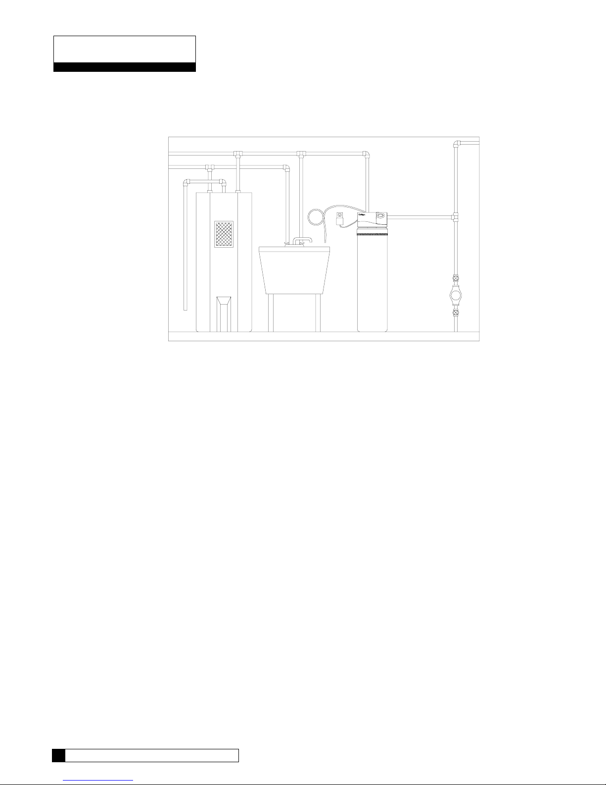
Refer to Figure 1 for system placement.
• Set the media tank on a solid, level surface near water, drain and electrical facilities.
FILLING PROCEDURE
Heater
Treated Water Out
Drain Line
Air Gap
FIG. 1
Raw Water In
Filter
To
Hose
Bibs
Water
Meter
or
Pump
FILTR-CLEER WATER FILTER
The 9" Filtr-Cleer filters are shipped with one media pack, and the media for the 12" Filtr-Cleer filters are shipped
with two media packs. The Filtr-Cleer media needs to be loaded into the tank according to the following procedure
to ensure its proper operation. Verify that you have the correct amounts of media on site prior to loading the tank.
• Cover the top of the manifold with a clean rag.
• Place a wide-mouth funnel in the tank opening.
• Open the media pack(s) by cutting along the bottom of the carton and lifting up to expose the four individual
media packages. Notice: The performance of the filter may be severely affected if the media are not added in
the proper sequence shown.
• With no water in the tank, slowly pour the Cullsan U media into the tank.
• With no water in the tank, slowly pour the Cullsan G-50 media into the tank and level.
• With no water in the tank, slowly pour the Cullsan A media into the tank and level.
• Slowly pour the Cullcite® media into the tank and level.
• Thread the inlet strainer into the tank until it bottoms out.
CULLAR FILTERS
The 9" Cullar filters are shipped with 3/4 cubic foot carton of carbon and a 20 lb bag of Cullsan underbedding, the
12" Cullar filters are shipped with 2 - 3/4 cubic foot cartons of carbon and a 30 lb bag of Cullsan underbedding..
• Cover the top of the manifold with a clean rag.
• Place a wide mouth funnel in the tank opening.
• Open the bag of Cullsan underbedding. Pour the entire contents into the tank. Shake the tank to level the media.
• Open the bag of carbon. Slowly pour the carbon into the tank via the funnel. The carbon should be within 17"19" of the top of the tank for the 9" and within 15"-17" on the 12" filters.
• Thread the inlet strainer into the tank until it bottoms out.
• Fill the tank with water and allow the media to soak for 24-48 hours. The water level in the tank will decrease as
the media soaks up water. Add water to the tank to keep the media submerged so all of the media gets saturated.
6 CULLIGAN GOLD SERIES WATER FILTERS
Page 9
CULLNEU FILTERS
Cullneu filters are shipped with 2 bags of Cullneu with 9" filters and 3 bags of Cullneu with 12" filters.
• Cover the top of the manifold with a clean rag.
• Place a wide mouth funnel in the tank opening. The Cullneu media should be added with no water in the tank.
• For 9" Cullneu filters, slowly pour the contents of both bags of media into the tank, the media will be within 13"
of the top of the tank.
• For 12" Cullneu filters, slowly pour the contents of the three bags of media into the tank, the media will be
within 18" of the top of the tank.
• Thread the inlet strainer into the tank until it bottoms out.
NOTICE: DO NOT OVERFILL. Overfilling will result in excess media being lost to drain during backwash,
possibly plugging the control valve. Shake the tank to level the media.
MOUNT THE CONTROL VALVE
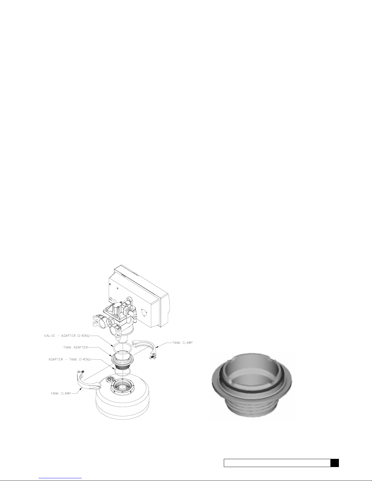
See Figure 2 for a visual on mounting the control valve to the tank.
• Assemble the o-rings, located in the parts part, to the tank adapter.
• The valve adapter o-ring sits on the first step on the adapter. See Figure 3.
NOTICE: Do not push the top o-ring down to the flange surface on the adapter.
NOTICE: The larger of the two o-rings in the parts pack goes between the adapter and the valve, do not stretch
the smaller o-ring onto the top of the tank adapter.
• Lubricate the large inside bore of the valve body, the top o-ring on the tank adapter and the outlet manifold o-ring
with silicone lubricant.
• Screw the adapter into the tank until the adapter bottoms out on the tank flange.
NOTICE: The adapter only needs to be tightened hand-tight to the tank flange.
• Align the manifold with the center opening in the valve, and press the valve onto the adapter firmly.
NOTICE: Make sure to push the valve straight down onto the manifold. If the valve is cocked it may cause the
o-ring to slip off the manifold.
• Assemble the tank clamp to the control, and tighten the clamp screw.
NOTICE: The clamp and valve will be able to rotate on the tank until pressure is applied. Align the control
onto the tank prior to tightening the clamp. The o-ring may cut or tear if the control is rotated after the clamp
is tightened.
FIG. 2
FIG. 3
INSTALLATION 7
Page 10
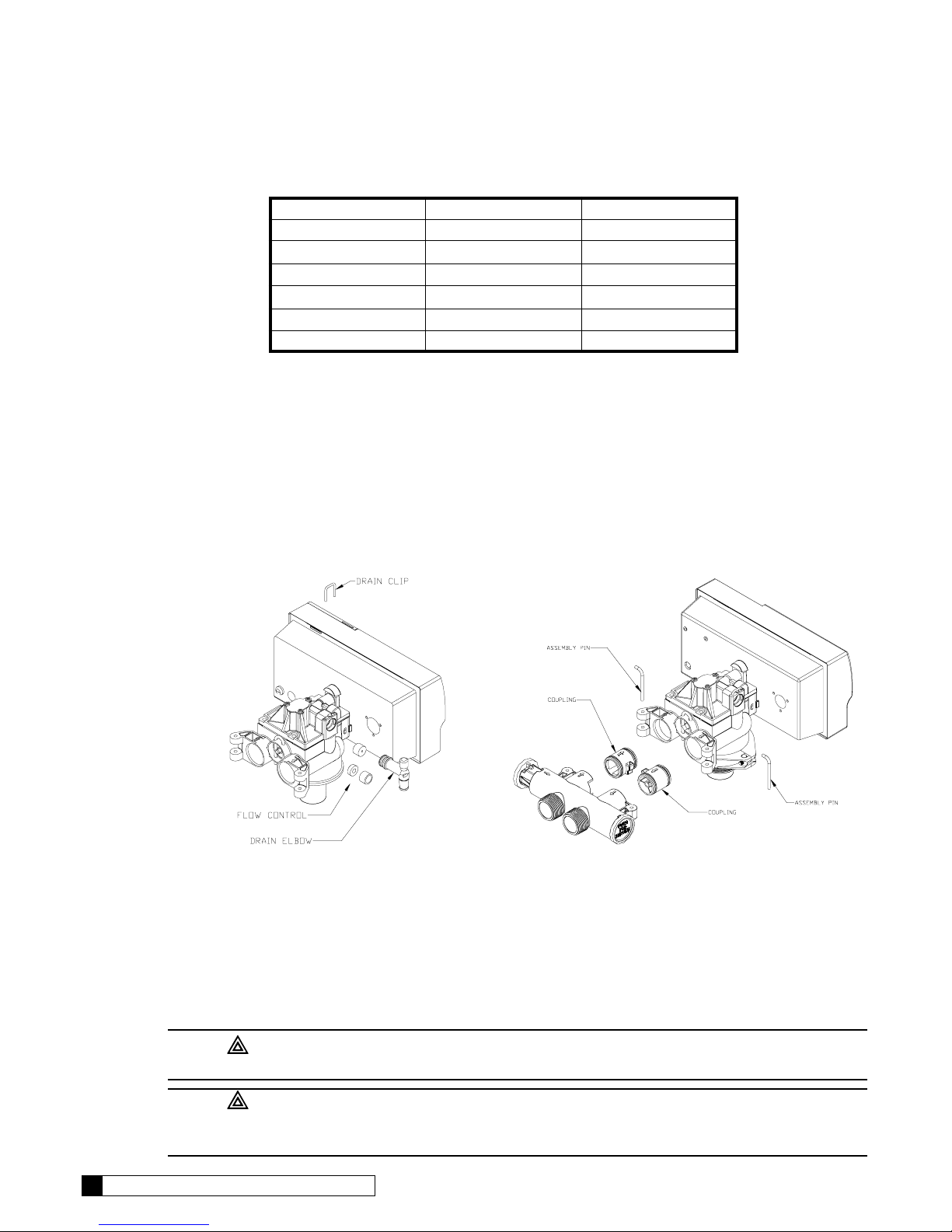
PROPER FLOW CONTROL INSTALLATION
As shipped from the factory, each control is equipped with a 2.0 gpm flow control for the 9" Cullar filters. Addi-
tional flow controls are included in the parts pack with each control for conversion for use with other filter tanks.
Refer to Table 1 for installation of the proper flow control.
TABLE 1
Filter Flow Control Color
9" Cullar 2.0 gpm Brown
12" Cullar 5.5 gpm Black
9" Cullneu 3.5 gpm Green
12" Cullneu 5.5 gpm Black
9" Filtr-Cleer 4.5 gpm Red
12" Filtr-Cleer 7.0 gpm* Black (Thin)
* Use with flow control spacer provided. Figure 4 shows installation of the flow control with the spacer.
For the backwash flow control conversion, refer to figure 4 and the instructions listed below.
• Remove the drain clip and pull the drain elbow straight off.
• Remove thebackwash flow control located behind the elbow. Put the flow control specified in Table 1 in its place.
NOTICE: For the 12" Filtr-Cleer, insert the plastic spacer after the 7 gpm flow control washer. See Figure 4.
NOTICE: The number on the flow control should face into the valve body.
• Insert the drain elbow back into the valve body and re-assembly the drain clip.
FIG. 4 FIG. 5
PLUMBING CONNECTIONS
Shipped with each filter is a Culligan bypass valve, which is used to connect the softener to the plumbing system.
The bypass valve can be directly plumbed into the system, or can be connected with the optional sweat
connection kit, P/N 01-0107-83.
CAUTION: Close the inlet supply line and relieve system pressure before
cutting into the plumbing! Flooding could result!
CAUTION: When making sweat connections, use care to keep heat away from the
plastic nuts used to connect the plumbing to the bypass. Damage to these components
may result otherwise.
8 CULLIGAN GOLD SERIES WATER FILTERS
Page 11
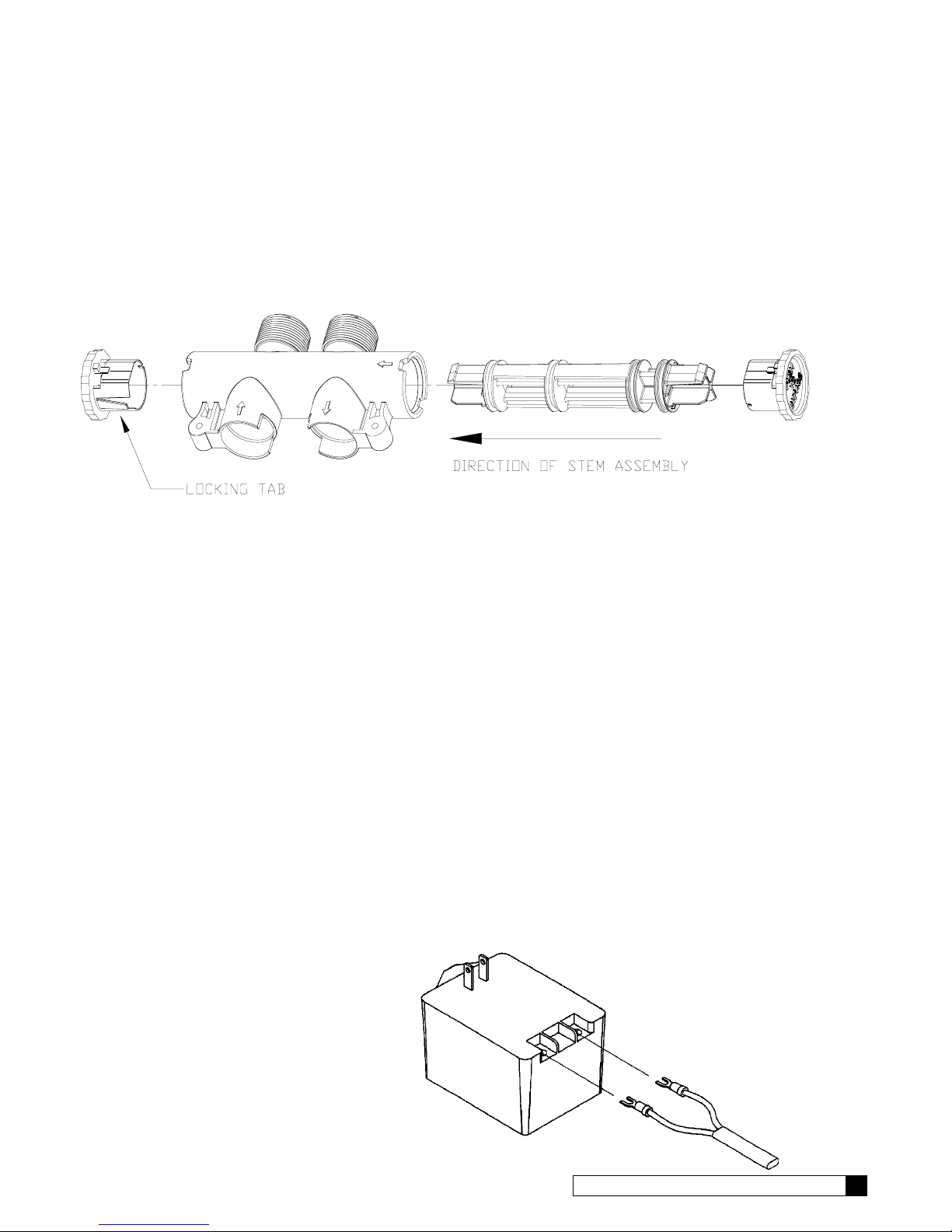
BYPASS VALVE INSTALLATION
The bypass valve connects directly to the control valve with a pair of couplings and two assembly pins (Figure 5).
Lubricate all o-rings on the couplings with silicone lubricant.
NOTICE: The bypass stem can only be removed from valve on the bypass side (red knob). The bypass valve is
designed so that it can be flipped over, with the bypass (red) knob on the left side of the valve. This will need to
be taken into consideration if the control is plumbed in close to a wall which may prevent the stem from being
easily removed.
The bypass valve has knobs that easily snap on and off of the stem. A screwdriver can be used to depress the snap
lever on the stem for knob removal. The knobs have alignment tabs that mate into the notches in the bypass body
to ensure that the stem is properly aligned in the bypass body. The service knob (blue) has a locking feature, which
must be drpressed in order to shift the stem out of the bypass position (Figure 6).
FIG. 6
NOTICE: If the ground from the electrical panel or breaker box to the water meter or underground copper pipe
is tied to the copper water lines and these lines are cut during installation of the bypass valve, an approved
grounding strap must be used between the two lines that have been cut in order to maintain continuity. The length
of the grounding strap will depend upon the number of units being installed. In all cases where metal pipe was
originally used and is later interrupted by the bypass valve to maintain proper metallic pipe bonding, an
approved ground clamp c/w not less than #6 copper conductor must be used for continuity. Check your local
electrical code for the correct clamp and cable size.
DRAIN LINE CONNECTION
Refer to Table 2, page 11 under the applicable tank size for drain line length and height limitations.
• Remove 1/2” pipe clamp from the small parts pack included with the control.
• Route a length of 1/2” drain line from the drain elbow to the drain.
• Fasten the drain line to the elbow with the clamp.
• Secure the drain line to prevent its movement during regeneration. When discharging into a sink, or open floor
drain, a loop in the end of the tube will keep it filled with water and will reduce splashing at the beginning of each
regeneration.
NOTICE: Waste connections or drain outlets shall be designed and constructed to provide for connection to the
sanitary waste system through an air gap of 2 pipe diameters or 1 inch, whichever is larger.
NOTICE: Observe all plumbing codes. Most codes require an anti-siphon device or air gap at the discharge
point. The system and installation must comply with state and local laws and regulations.
ELECTRICAL CONNECTION
The power cord needs to be connected to the plugin transformer. Figure 7 shows the power cord
attachement to the transformer.
NOTICE: Observe all state and local electrical
codes.
NOTICE: The plug-in transformer is rated for
indoor installations only.
FIG. 7
INSTALLATION 9
Page 12
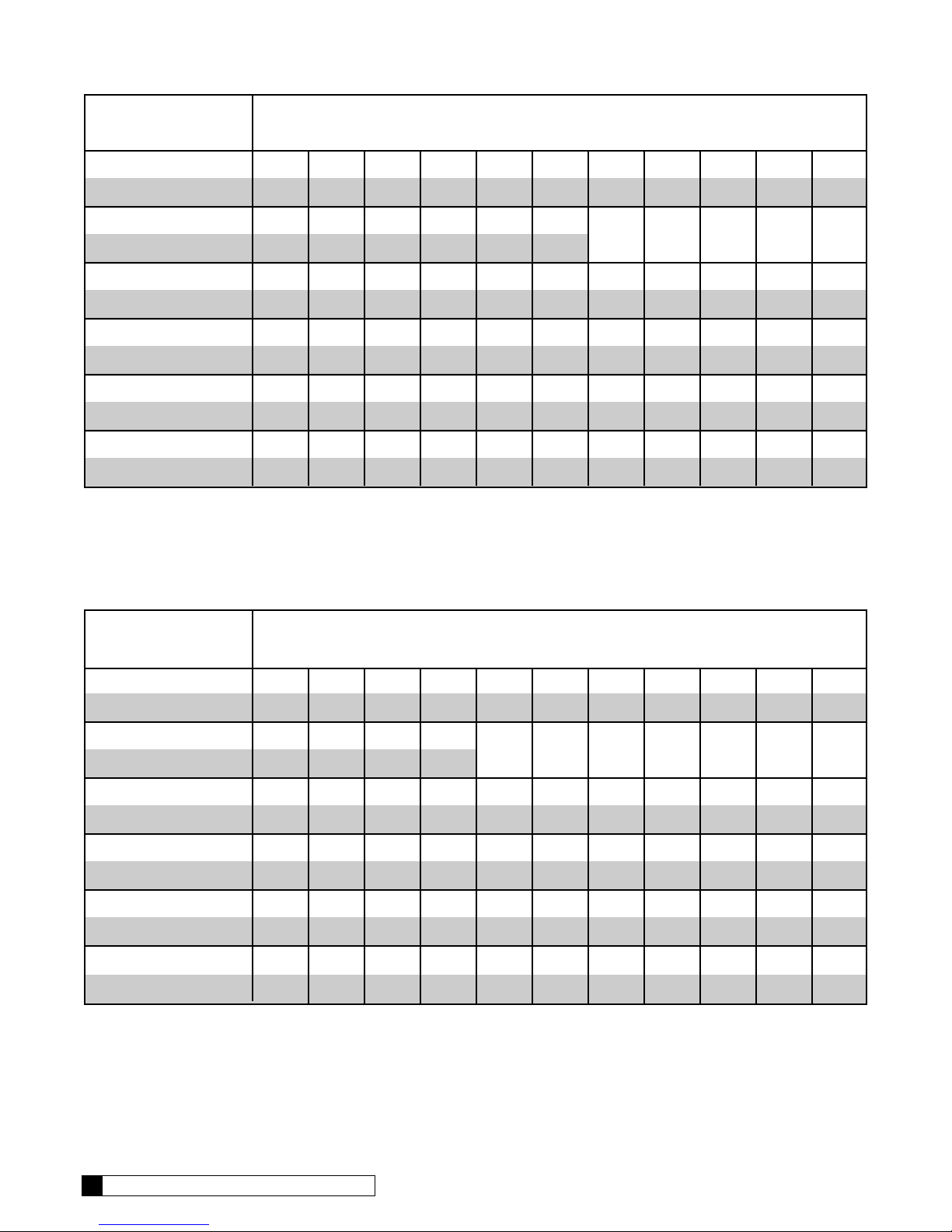
9-INCH MODELS
Average Water
Pressure Height of Drain Discharge Above Floor Upon Which Filter Sets
psi 4 in. 1 ft 2 ft 3 ft 4 ft 5 ft 6 ft 7 ft 8 ft 9 ft 10 ft
kPa 0.1 m 0.3 m 0.6 m 0.9 m 1.2 m 1.5 m 1.8 m 2.1 m 2.4 m 2.7 m 3.1 m
30 56 50 40 30 20 10
210 17.1 15.3 12.2 9.2 6.1 3.1
50 112 106 96 86 76 66 56 46 36 26 16
350 34.2 32.3 29.3 26.2 23.2 20.1 17.1 14.0 11.0 7.9 4.9
70 143 137 127 117 107 97 87 77 67 57 47
480 43.6 41.8 38.7 35.7 32.6 29.6 26.5 23.5 20.4 17.4 14.3
90 153 147 137 127 117 107 97 87 77 67 57
620 46.7 44.8 41.8 38.7 35.7 32.6 29.6 26.5 23.5 20.4 17.4
120 159 153 143 133 123 113 103 93 83 73 63
830 48.5 46.7 43.6 40.6 37.5 34.5 31.4 38.4 25.3 22.3 19.2
TABLE 1 - DRIAN LINE LENGTH AND HEIGHT LIMITATIONS
12-INCH MODELS
Average Water
Pressure Height of Drain Discharge Above Floor Upon Which Filter Sets
psi 4 in. 1 ft 2 ft 3 ft 4 ft 5 ft 6 ft 7 ft 8 ft 9 ft 10 ft
kPa 0.1 m 0.3 m 0.6 m 0.9 m 1.2 m 1.5 m 1.8 m 2.1 m 2.4 m 2.7 m 3.1 m
30 44 38 28 18
210 13.4 11.6 8.5 5.5
50 103 97 87 77 67 57 47 37 27 17 7
350 31.4 29.6 26.5 23.5 20.4 17.4 14.3 11.3 8.2 5.2 2.1
70 129 123 113 103 93 83 73 63 53 43 33
480 39.3 37.5 34.5 31.4 28.4 25.3 22.3 19.2 16.2 13.1 10.1
90 145 139 129 119 109 99 89 79 69 59 49
620 44.2 42.4 39.3 36.3 33.2 30.2 27.1 24.1 21.0 18.0 14.9
120 153 147 137 127 117 107 97 87 77 67 57
830 46.7 44.8 41.8 38.7 35.7 32.6 29.6 26.5 23.5 20.4 17.4
10 CULLIGAN GOLD SERIES WATER FILTERS
Page 13
Settings
The Culligan Automatic Water Filter is designed to perform efficiently on a wide range of water supplies. In order
to ensure proper operation of the filter, and before initiating the initial recharge and putting the unit into service, the
following settings need to be made.
BACKWASH
The backwash setting is important in that backwashing expands and loosens the media bed. This flushes away the
particulate matter that has accumulated in the bed. The backwash interval is preset at the factory for 10 minutes,
which is adequate for most water supplies. It is recommended that the backwash cycle last just long enough so that
the effluent from the drain line is clear. Backwash too long and water is wasted, not long enough and the tank
becomes fouled with sediment. Refer to the programming section for instructions on adjusting the backwash time.
PAUSE CYCLE
Because this Automatic Water Filter shares it timer with other water conditioning products, it momentarilly stops in
a pause cycle. This setting is used in other controls for the eduction and rinsing of salt, or other regenerant
chemicals. The pause cycle is factory set at 10 minutes. Refer to the programming section for instructions on
adjusting the pause time.
RAPID RINSE
The rapid rinse setting settles and compacts the media after backwashing and flushes any residual particulate
matter from the bottom of the filter bed before returing the filter to the service position. The rapid rinse setting is
factory set at 10 minutes. Refer to the programming section for instructions on adjusting the rapid rinse time.
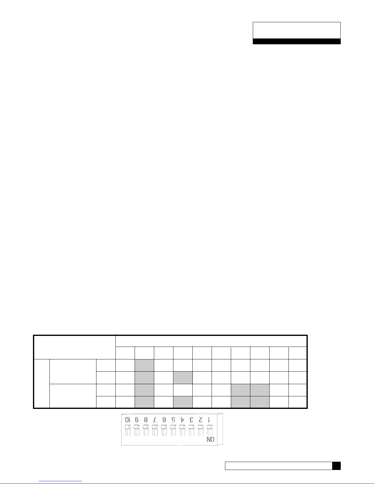
DIP SWITCH SETTINGS
The microprocessor has several dip switches that can be switched for various additional functions. Listed are the
functions for the dip switches used on the Gold Series Filter controls.
Dip Switch Function Default (OFF) Position
2 Filter / Softener Softener
4 9" - 12" Tank Settings 9" Tank
6 Delay vs. Immediate Regeneration Delayed Regeneration
7 English vs. Metric Settings English Settings
8 12 or 24 Hour Clock 12 Hour Clock
Refer to Table 3 and Figure 8 for setting the dipswitches. Factory shipped all dip switches are in the off position.
NOTICE: The end of a ball point pen works well to flip the dip switches as little force is required to flip the
switches. DO NOT use a pencil as the graphite may damage the dip switch.
TABLE 3 - Dip Switch Setting
DIP SWITCHES
1234567 8910
ENGLISH 9" OFF ON OFF OFF OFF OFF OFF OFF OFF OFF
SETTINGS 12" OFF ON OFF ON OFF OFF OFF OFF OFF OFF
METRIC 9" OFF ON OFF OFF OFF OFF ON ON OFF OFF
SETTINGS 12" OFF ON OFF ON OFF OFF ON ON OFF OFF
CONTROL TYPE
FIG. 8
SETTINGS 11
Page 14
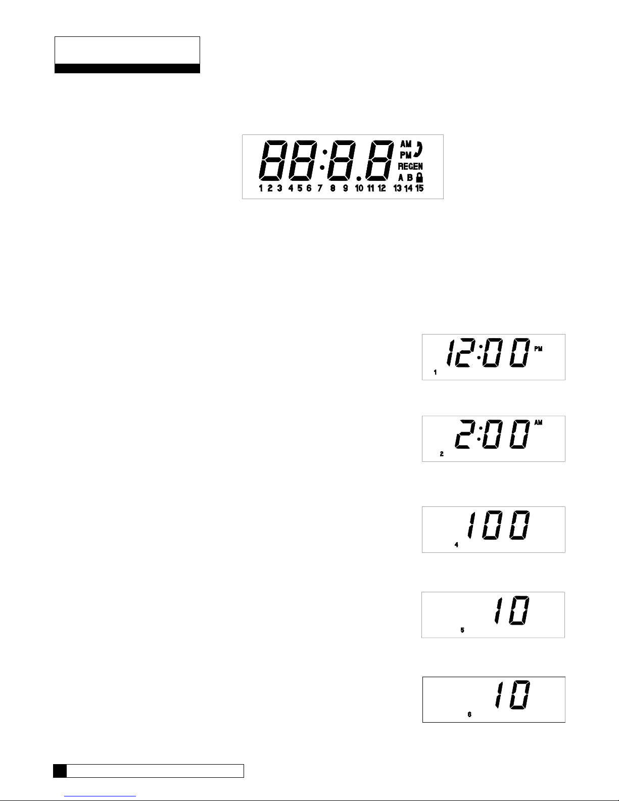
Programming
Make sure the inlet water supply is turned off, then supply power to the timer. The display will power up flashing
"12:00 PM". After 1 minute the motor will energize and cycle the control, without stopping, to the home position.
This is required to ensure that the control is in the home position.
The timer uses four buttons:
1. STATUS: Advance timer through display options.
2. UP ARROW: Increase the setting.
3. DOWN ARROW: Decrease the setting.
4. REGEN.: Initiate a manual regeneration.
SETTING THE MICROPROCESSOR
1. With a flashing or blank display, pressing the status button twice will
move to the Time-of-Day adjustment. Adjust the time by using the up
and down arrows. A number “1” will appear at the bottom of the display
while in this mode.
FIG. 11 - Circuit Board Display
Press ▲ to increase or
▼ to decrease
2. Press status again, this displays the Time-of-Regeneration for delayed
units, adjust using the up and down arrows. A number “2” will appear
at the bottom of the display while in this mode.
3. Press status again, the disply will skip setting "3" and a number “4” will
appear at the bottom of the display. This setting is not used, and any
changes made will not affect the operation of the microprocessor.
4. Press status again, this displays the Backwash Time in minutes. The
setting can be adjusted between 1 and 40 minutes by using the up and
down arrows. A number “5” will appear at the bottom of the display
while in this mode.
5. Press status again to display the Pause Time in minutes. The settings
can be adjusted between 1 and 15 minutes using the up and down
arrows. A number “6” will appear at the bottom of the display while in
this mode.
Press ▲ to increase or
▼ to decrease
Press ▲ to increase or
▼ to decrease
Press ▲ to increase or
▼ to decrease
12 CULLIGAN GOLD SERIES WATER FILTERS
Page 15
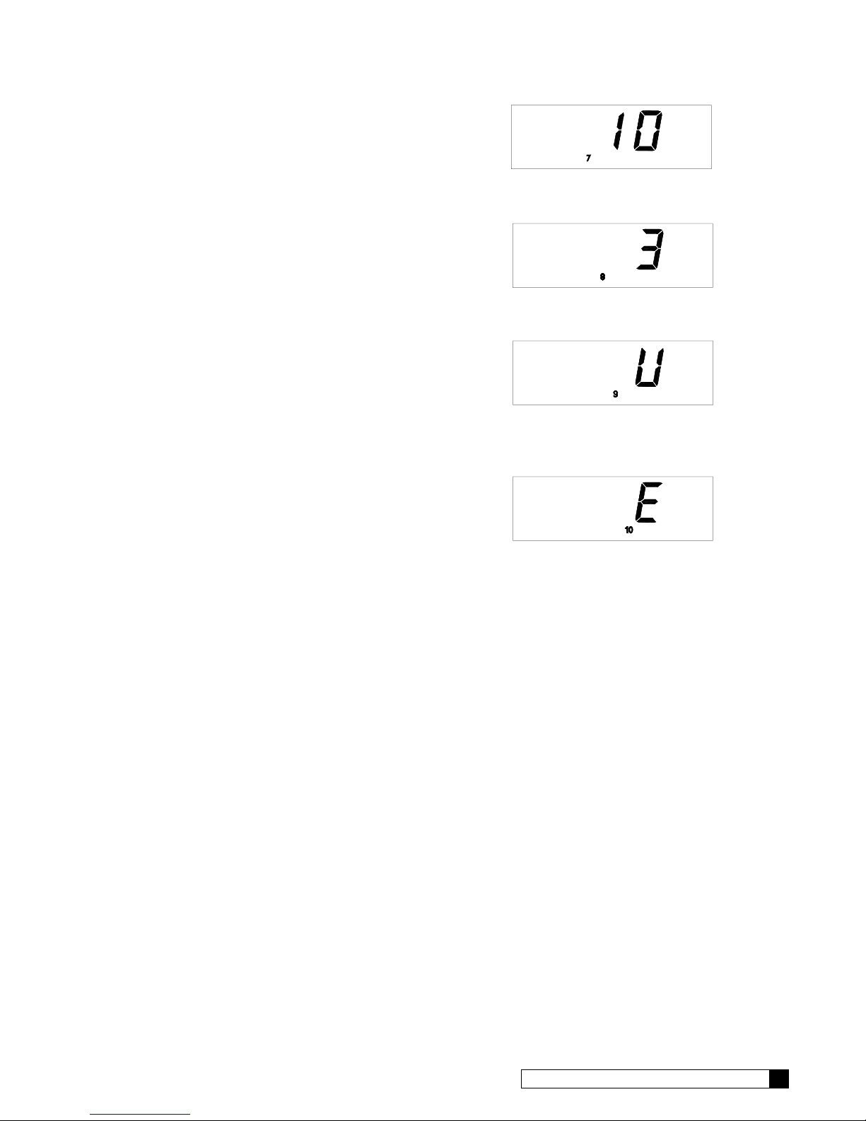
6. Press status again to display the Fast Rinse Time in minutes. The
setting can be adjusted from 5-30 minutes by using the up and down
arrows. A number “7” will appear at the bottom of the display while in
this mode.
7. Press status again, the display will show the Regeneration Interval.
The setting can be adjusted from 1-42 days using the up and down
arrows. A number “8” will appear at the bottom of the display while in
this mode.
8. Pressing status again will display the Lock/Unlock feature. A “U” in
the display signifies an unlocked microprocessor, while a “L” will lock
the settings except for the time of day. To toggle between the two
settings press both arrow keys simultaneously. A number “9” will
appear at the bottom of the display while in this mode.
9. Pressing status again brings up the ability to Enable/Disable the screen
blanking. To have the display constantly lit, press the up arrow, a “d”
for disable will appear in the display. Pressing the up arrow again
displays an “E”, signifying that display blanking is enabled. A number
“10” will appear at the bottom of the display while in this mode.
Press ▲ to increase or
▼ to decrease
Press ▲ to increase or
▼ to decrease
Press ▲ simultaneously
▼
Press ▲ to change
NOTICE: Programming changes are not locked into the microprocessor
memory until the control completes a regeneration cycle. To initiate a manual
regeneration, press the REGEN. button twice, the "REGEN" enunciator will
flash on the display. Refer to the Manual Cycling section on how to step
through the regeneration stages.
PROGRAMMING 13
Page 16
Manual Cycling
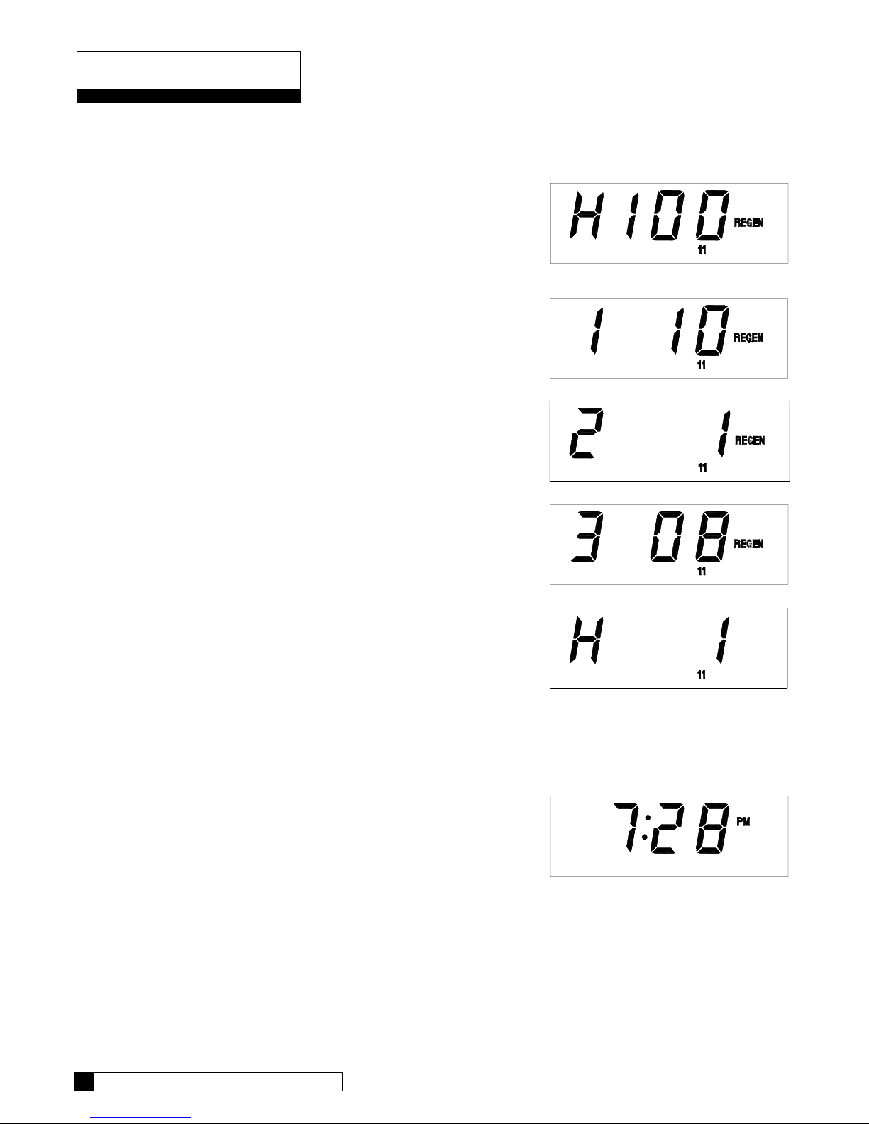
The Culligan microprocessor can be indexed through the various regeneration stages. For all steps, the cycle
numbers do not appear, or change, until the motor stops.
1. Press the status button to move past steps 1-10 until the
display is blank. Push the up arrow. The number “11” icon will
light up. An "H" will appear in the display. The control is in
the HOME position. Pressing the regen button once will light
the 'REGEN' icon.
2. Press the regen button one more time. The 'REGEN' icon will
blink, and the motor will advance the control. A '1' will appear.
The unit is now in the BACKWASH position. The numbers to
the right indicate the time remaining for the cycle.
3. Press the up arrow. A '2' will appear in the display, along with
the cycle time remaining. The control is in the PAUSE cycle.
4. Press the up arrow. A '3' will appear in the display, along with
the cycle time remaining. The control is now in the FAST
RINSE cycle.
5. Press the up arrow. An 'H' will appear in the display. The unit
is in the HOME position. The 'REGEN' enunciator is no longer
blinking.
NOTICE: Because the filter software is common to other products,
the display will initially display 'H 1', and will flip to the
value set in option 4, 'H 100' after 1 minute. It will then count
down too zero, count for 1 minute, and reset to the option 4
value. This does not affect the operation of the control.
6. Press the status key. Time-of-Day appears in the display.
14 CULLIGAN GOLD SERIES WATER FILTERS
Page 17
Service Check
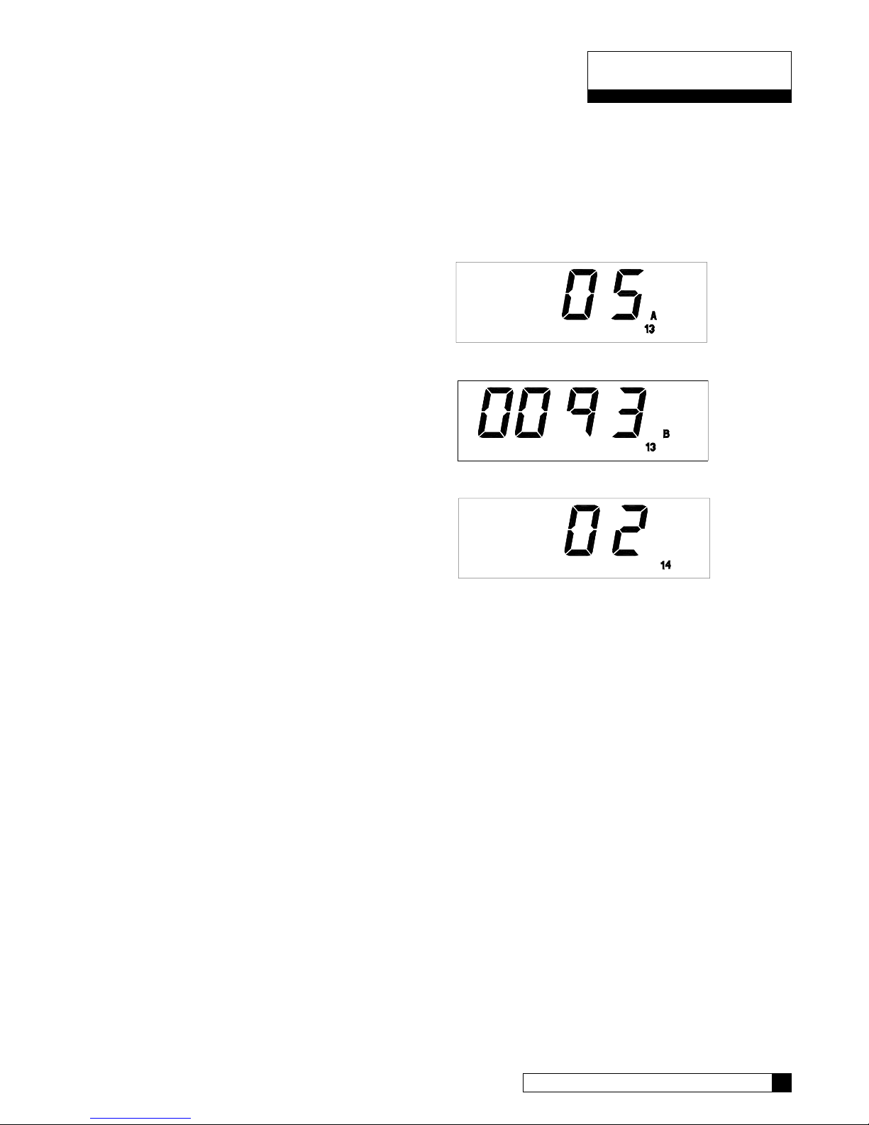
The service check mode allows one to view the instantaneous flow rate, the days since the last regeneration, the
total number of regenerations, the regenerations in the past fourteen days, and the gallons remaining.
To enter the service check mode, follow these steps:
1. Press the status key to move past steps 1-10 until the
display is blank.
2. Press the down arrow. The number '13' and an "A" will
light at the bottom of the display. The display will
indicate the number of regenerations that have
occurred in the last 14 days.
3. Press the down arrow. The number '13' and a 'B' will
light at the bottom of the display. The display will
indicate the total number of regenerations this control
has cycled through.
4. Press the down arrow. The number '14' will light at the
bottom of the display. The number in the display
indicates the number of days since last regeneration.
NOTICE: Pushing the up arrow at any of these displays will
immediately bring you to the control position display, the
number '11' will light at the bottom of the display.
SERVICE CHECK 15
Page 18

Operation
DISPLAY
There are two display modes on the Culligan microprocessor. As shipped from the factory, the display of the board
is initially set to turn off if there has been no keyboard activity after a 1 minute period. Touching any key will relight
the display. The display can be set so that it will always display the time. For information on changing the display
lighting option, refer to the programming section.
REGENERATION
There are several conditions that will cause the control to trip a regeneration. The 'REGEN' enunciator will light when
the control has signaled for a regeneration. The 'REGEN' enunciator will flash while the control is in regeneration.
The following are conditions that will call for regeneration:
1. When the time clock has counted past the set number of days.
2. At the preset time, when the 'REGEN.’ button is depressed once. 'REGEN.' will light.
3. Immediately, when the ‘REGEN.” button is depressed twice. 'REGEN.' will light and blink.
4. Immediately, if power to the unit has been off for more than 3 hours.
START-UP
• Close the main water supply valve.
• Set the bypass valve to the bypass position.
• Ensure that all faucets at the installation site are closed.
• Direct the drain line discharge into a bucket where flow can be observed.
• Plug the transformer into a 120 Volt, 60 Hz, single-phase receptacle.
• Wait 1 minute for the control to energize the motor and home itself.
• Set the timer to the correct time of day.
• Open the main supply valve.
• Initiate an immediate regeneration to move the control into the backwash position.
• Refer to the section on manual cycling for information on cycling the control through its positions.
• When in the backwash position, slowly shift the bypass to the service position until water flows.
• Allow the tank to fill slowly until water flows from the drain line.
• When the unit is filled with water, return the timer to the service position and proceed with setting the
microprocessor. Refer to the programming section.
• Initialte a full regeneration prior to leaving the installation site.
NOTICE: For Cullar and Cullneu models, bypass and unplug the control and allow the media to soak for 24 to
48 hours. After allowing the media to soak, plug the control in, shift the bypass to the service position, and verify
that the mircroprocessor settings are correct.
NOTICE: Unplugging the Culligan Gold Series Filter will not affect any of the timer settings. Once programmed
in, the settings will be stored indefinitely. In the event of a power failure the time-of-day setting will be stored for
1-2 days. If longer time storage is necessary, a battery backup is available. Refer to the Service
Manual for additional information.
BEFORE LEAVING THE INSTALLATION SITE
Explain the operation of the filter to the customer. Make sure the customer knows that there will be new sounds
associated with the recharging of the unit.
Check the approiate filter model box in the Owner's Guide, and then sign and date the corresponding performance
data sheet. Leave the Owner's Guide with the customer.
Clean up the unit and installation site, removing any soldering, or pipe threading, residues from the equipment and
surrounding area with a damp towel.
16 CULLIGAN GOLD SERIES WATER FILTERS
Page 19
Operation, Care and Maintenance
CULLNEU FILTER REFILLING
As water passes through a Cullneu water filter, the media slowly dissolvers and neutralizes the water. The rate at
which the Cullneu media dissolves depends on a number of factors such as temperature, flow rate and pH. Because
these factors are so variable, it is often difficult to determine how often new Cullneu media should be added. Tables
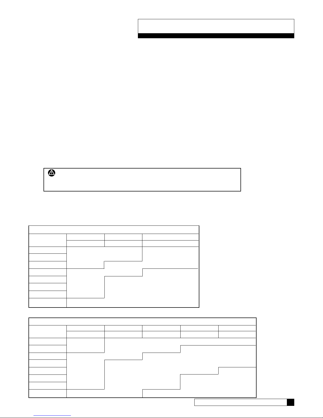
4 and 5 show the recommended intervals for inspection and replenishment of Cullneu media. The following
procedure should be used to determine when new media should be added.
• Press the 'REGEN.' button twice to initiate a recharge cycle.
• Unplug the unit when it stops in the backwash position, and shift the bypass valve to the bypass position.
• Disconnect the tank clamp on the valve and remove the valve from the tank.
• Remove the tank adapter, and the inlet strainer from the tank.
• Measure the distance from the top of the media to the top of the threads on the tank flange (This distance is
the freeboard). For 9" filters, if the freeboard is greater than 19 inches, add enough Cullneu to decrease the
freeboard to 13 inches. For the 12" filters, if the freeboard is greater than 24 inches, add enough Cullneu to
decrease the freeboard to 18 inches.
• Make sure that there is no Cullneu media on the o-ring sealing surface of the tank flange, and re-assemble
the inlet strainer and tank adapter. Assemble the control back to the adapter, and tighten the tank clamp.
• Place the bypass back into the service position, plug the unit back in, and allow the filter to complete its
recharge cycle.
WARNING: SOME WATER SUPPLIES CONTAIN POTENTIALLY HAZARDOUS
GASES. DO NOT INSPECT THE INTERIOR OF THE TANK USING A SPARK OR
HEAT SOURCE, OR AN EXPLOSION MAY RESULT.
NOTICE: It is possible to check the freeboard height by dropping a dowel rod, of 1/2" diameter or less, into the
A/S port hole, and then measuring how far in it drops. Marks could be made on the rod which could be used to
quickly gage if the media needs to be replenished.
TABLE 4
9-INCH NEUTRALIZERS; MINERAL REPLENISHMENT INTERVAL
CO2 (GPG) 2 Persons 3 4
150 gpd 225 300
3 Every
4 Every 6 3
5 Months Every Months
6 3 Months
7 Every
8 3 USE
9 Months CHEMICAL
10 FEED
TABLE 5
12-INCH NEUTRALIZERS; MINERAL REPLENISHMENT INTERVAL
CO2 (GPG) 2 Persons 3456
150 gpd 225 300 375 450
3 Annually Every
4 6 Every
5 Months 3
6 Every Every Months
76 3
8 Months Months USE
9 CHEMICAL
10 FEED
OPERATION, CARE AND MAINTENANCE 17
Page 20
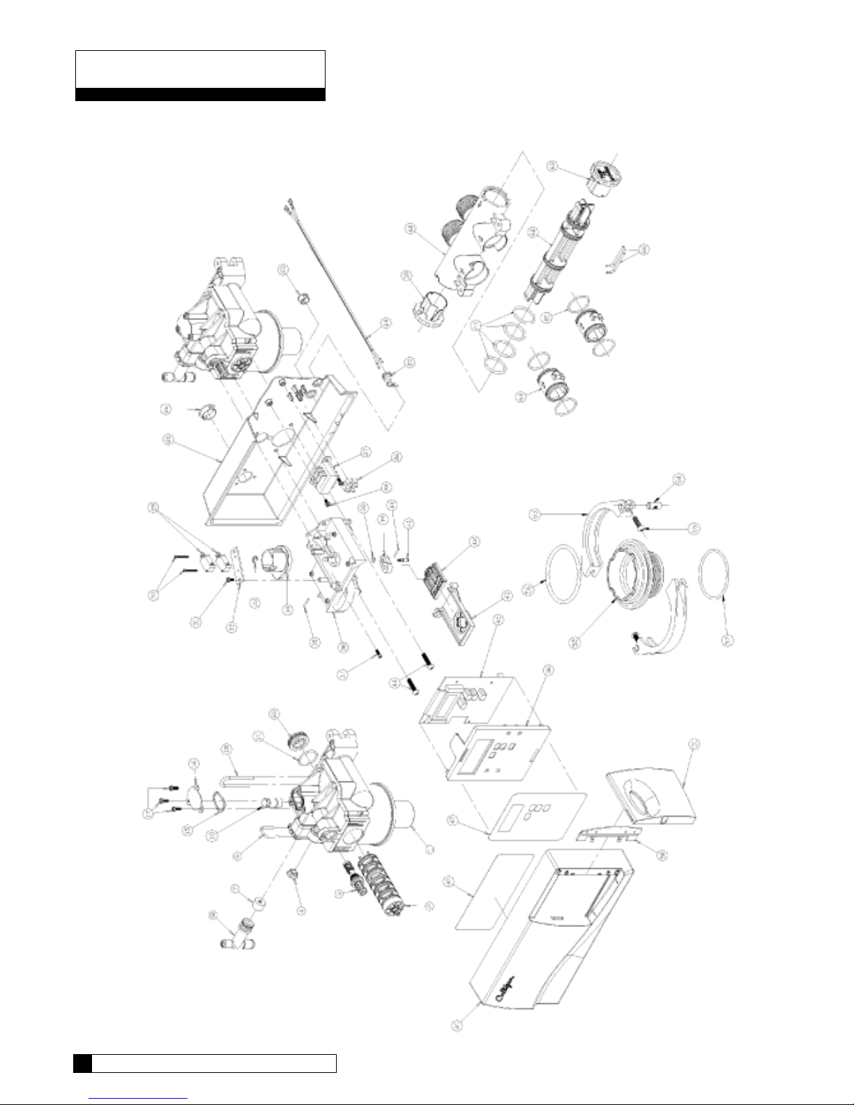
Parts List - Control
18 CULLIGAN GOLD SERIES WATER FILTERS
Page 21

41 01-0126-49 Follower
42 01-0126-48 Yoke
43 01-0126-47 Bracket
44 00-3184-52 Screw
45 01-0130-94 Circuit Board
46 01-0140-28 Circuit Board Mounting Plate
47 01-0128-68 Timer Label
48 01-8823-57 Setting Label, Filter
49 01-0140-26 Cover
50 01-0140-30 Hinge
51 01-0140-29 Door
52 01-0139-58 Tank Adapter
53 01-0139-59 Tank Clamp
54 01-0136-69 Clamp Pin
55 00-318-383 Screw
56 01-0140-31 O-Ring
57 00-4400-52 O-Ring
59 01-0139-63 Knob, Bypass - Service
60 01-0139-61 Bypass Body, 1-1/4" NPT
61 01-0130-95 O-Ring
62 01-0139-65 Bypass Stem
63 01-0139-64 Knob, Bypass - Bypass
64 01-0080-66 Coupling
* 01-0129-56 Wall Mount Transformer
* 01-0136-70 1-1/4" Bypass Assembly
* 01-0129-58 Wire Harness, Cam
* 00-4517-01 Hose Clamp, Drain
65 01-0090-99 O-Ring
66 01-0090-75 Assembly Pin
* 01-0138-39 Back-up Battery
‡ Recommended Spare Parts
* Not Illustrated
00-3316-37 Backwash Restrictor, 4.5 GPM
00-4010-34 Backwash Restrictor, 5.5 GPM
P0-3316-36 Backwash Restrictor, 3.5 GPM (10/Kit)
1 01-0139-76 Control Valve
— 01-0145-65 Control Valve Assembly - Gold Series
Item Part No. Description Item Part No. Description
‡ 2 01-0130-83 Seal Pack Assembly
‡ 3 01-0012-58 Eductor Sleeve Filter
4 00-4464-75 Plug
7 P0-3316-35 Backwash Restrictor, 2.0 GPM (10/Kit)
‡ * P0-4479-86 O-Ring, Eductor Sleeve, Small O-Ring (25/Kit)
‡ * P0-3084-07 O-Ring, Eductor Sleeve, Large O-Ring (25/Kit)
A0-7080-08 Backwash Restrictor, 7 GPM (Needs Spacer)
01-0144-26 Backwash Spacer, 7 GPM (With A0-7080-08)
8 00-4468-35 Drain Elbow Assembly w/O-Ring
9 00-4473-87 Retainer, Drain Elbow
‡ 10 00-4486-68 Plug, Eductor
‡ * P0-3084-37 O-Ring, Eductor Plug (25/Kit)
‡ 15 00-4457-97 Gasket
20 00-4481-26 Rear Body Plug
21 01-0140-27 Control Back Plate
16 00-4010-22 Eductor Port Cover
17 00-4486-87 Screw
18 00-4481-28 Retainer, Rear Body Plug
22 01-0139-66 Plug, 1.000" Snap-in
‡ 19 P0-4449-14 O-Ring, Rear Seal (10/Kit)
23 01-0064-98 Plug, .562" Snap-in
24 A0-4880-16 Power Cord
25 01-0003-72 Strain Relief
26 00-3318-48 Terminal Strip
27 01-0128-45 Transformer
28 P1-0084-73 Screw (10/Kit)
‡ 29 00-4452-44 Switch
30 00-4486-86 Screw
31 00-3184-55 Screw
32 00-4010-40 Switch Bracket
33 P1-0130-43 Retaining E-Ring (10/Kit)
34 01-0130-31 Cam
35 00-4435-59 Roll Pin
36 01-0141-79 Drive Motor & Bracket Assembly 24V/60Hz
37 01-0017-84 Screw
38 00-3183-54 Nut
39 00-4452-21 Bellcrank
40 00-4452-46 Roll Pin
PARTS LIST 19
Page 22
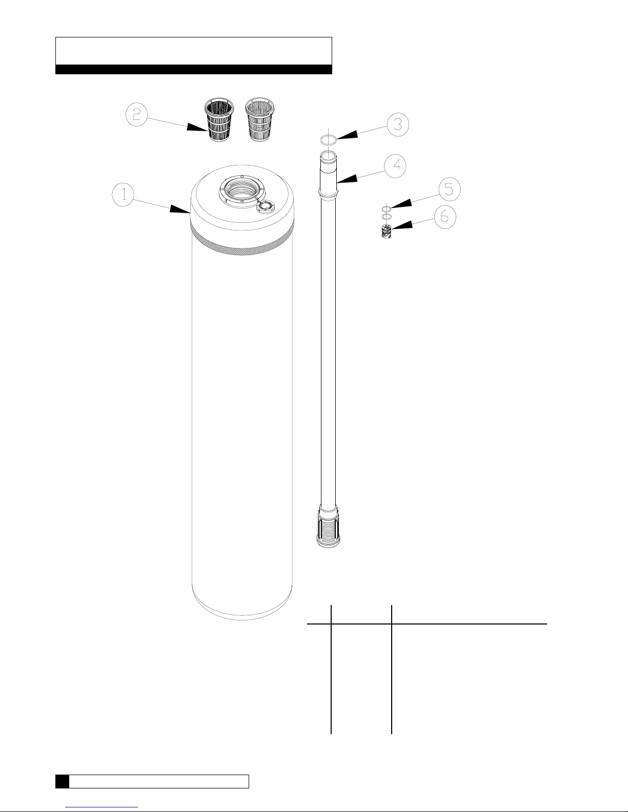
Parts List - Tank Assembly
20 CULLIGAN GOLD SERIES WATER FILTERS
Item Part Number Description Qty.
1 01-0112-82 Tank Replacement, 9", Empty
01-0112-83 Tank Replacement, 12", Empty
2 01-0098-47 Top Strainer - Fine Slot
01-0111-95 Top Strainer - Wide Slot 1
3 01-0090-99 O-Ring, Manifold 1
4 01-0096-15 Outlet Manifold 1
5 00-4704-29 O-Ring, Plug 2
6 01-0100-46 Plug 1
 Loading...