

Page 1

Installation and Operation Manual
Next Generation On-Camera Prompter Displays
Model CSF10-SDI Prompter
Page 2

2
1 Contents
CueScript CSF10-SDI Prompter ........................................................................................................................... 6
2 CueScript Prompter Features ..................................................................................................................... 6
3 Display Technical Specifications ................................................................................................................. 6
3.1 Model CSF10-SDI .................................................................................................................................. 6
4 Signal Inputs ................................................................................................................................................ 6
5 Power Requirements .................................................................................................................................. 7
6 Dimensions ................................................................................................................................................. 7
7 Environmental............................................................................................................................................. 7
8 Routine Maintenance ................................................................................................................................. 7
9 Installation .................................................................................................................................................. 7
9.1 Inspecting New Prompter and Accessories ......................................................................................... 7
9.2 Installation Requirements .................................................................................................................... 7
10 Connectors and Controls ............................................................................................................................ 8
10.1 DC Power .......................................................................................................................................... 8
10.2 Composite Video In and Out ............................................................................................................ 9
10.3 VGA ................................................................................................................................................... 9
10.4 SDI ..................................................................................................................................................... 9
10.5 USB Out ............................................................................................................................................ 9
11 Operation .................................................................................................................................................. 10
11.1 Control Panel .................................................................................................................................. 10
11.2 Power Button .................................................................................................................................. 10
11.3 Rotate Button ................................................................................................................................. 10
11.4 Menu keys ...................................................................................................................................... 10
11.5 Tally Controls .................................................................................................................................. 11
11.6 LCD Controller Menu ...................................................................................................................... 11
12 OSD Menu Layout ..................................................................................................................................... 11
12.1 To enter next level .......................................................................................................................... 11
12.2 To exit from current level ............................................................................................................... 11
13 INFO Menu ................................................................................................................................................ 12
13.1 MODEL ............................................................................................................................................ 12
13.2 INPUT .............................................................................................................................................. 12
Page 3

3
13.3 FORMAT .......................................................................................................................................... 12
13.4 COLOR TEMP .................................................................................................................................. 12
13.5 RANGE ............................................................................................................................................ 12
13.6 VERSION .......................................................................................................................................... 12
14 INPUT Menu .............................................................................................................................................. 13
14.1 RETURN ........................................................................................................................................... 13
14.2 INPUT .............................................................................................................................................. 13
14.3 SETUP LEVEL ................................................................................................................................... 13
14.4 ANALOG CALIBRATE ....................................................................................................................... 13
15 PICTURE..................................................................................................................................................... 14
15.1 RETURN ........................................................................................................................................... 14
15.2 BRIGHT ............................................................................................................................................ 14
15.3 CONTRAST ...................................................................................................................................... 14
15.4 CHROMA ......................................................................................................................................... 14
15.5 SHARPNESS ..................................................................................................................................... 14
15.6 GAMMA .......................................................................................................................................... 14
15.7 RESET TO DEFAULT ......................................................................................................................... 14
16 COLOR ....................................................................................................................................................... 15
16.1 RETURN ........................................................................................................................................... 15
16.2 COLOR TEMP .................................................................................................................................. 15
16.3 BIAS ................................................................................................................................................. 15
16.4 GAIN ................................................................................................................................................ 15
17 SCREEN ...................................................................................................................................................... 16
17.1 RETURN ........................................................................................................................................... 16
17.2 SCAN ............................................................................................................................................... 16
17.3 ASPECT ............................................................................................................................................ 16
17.4 MONO/COLOR ................................................................................................................................ 16
17.5 FLIP H/FLIP V ................................................................................................................................... 16
18 MARKER .................................................................................................................................................... 17
18.1 RETURN ........................................................................................................................................... 17
18.2 MARKER .......................................................................................................................................... 17
18.3 CENTER ........................................................................................................................................... 17
Page 4

4
18.4 ASPECT ............................................................................................................................................ 17
18.5 SAFETY ............................................................................................................................................ 17
18.6 CROSSHATCH .................................................................................................................................. 18
18.7 MARKER MAT ................................................................................................................................. 18
18.8 LINE THICKNESS .............................................................................................................................. 18
19 AUDIO ....................................................................................................................................................... 18
19.1 RETURN ........................................................................................................................................... 18
19.2 FRONT VOLUME ............................................................................................................................. 18
19.3 REAR VOLUME(Optional)................................................................................................................ 18
20 LEVEL METER ............................................................................................................................................ 18
20.1 What is Audio a Level Meter? ........................................................................................................ 18
20.2 LEVEL METER .................................................................................................................................. 18
21 WAVEFORM .............................................................................................................................................. 19
21.1 What is a Waveform Monitor? ....................................................................................................... 19
21.2 RETURN ........................................................................................................................................... 19
21.3 WAVEFORM .................................................................................................................................... 19
22 VECTORSCOPE ........................................................................................................................................... 20
22.1 What is a Vector Scope? ................................................................................................................. 20
22.2 RETURN ........................................................................................................................................... 20
22.3 VECTORSCOPE ................................................................................................................................ 20
23 ClipGuide ................................................................................................................................................... 21
23.1 RETURN ........................................................................................................................................... 21
23.2 CLIPGUIDE ....................................................................................................................................... 21
23.3 MODE .............................................................................................................................................. 21
23.4 Y UPPER LIMIT ................................................................................................................................ 21
23.5 Y LOWER LIMIT ............................................................................................................................... 21
23.6 C UPPER LIMIT ................................................................................................................................ 21
23.7 C LOWER LIMIT ............................................................................................................................... 21
24 USER ASSIGN ............................................................................................................................................. 22
24.1 RETURN ........................................................................................................................................... 22
24.2 Available Options ............................................................................................................................ 22
24.2.1 INPUTS ........................................................................................................................................ 22
Page 5

5
24.2.2 Screen Modes ............................................................................................................................. 22
24.2.3 Screen Modes ............................................................................................................................. 22
24.2.4 Utility ........................................................................................................................................... 22
24.2.5 Audio ........................................................................................................................................... 22
25 SETUP ........................................................................................................................................................ 23
25.1 RETURN ........................................................................................................................................... 23
25.2 FORMAT DISPLAY ........................................................................................................................... 23
25.3 TIMECODE....................................................................................................................................... 23
25.4 USERBIT .......................................................................................................................................... 23
25.5 PICTURE DELAY ............................................................................................................................... 23
25.6 POWER SAVE .................................................................................................................................. 23
25.7 KEY LOCK ......................................................................................................................................... 23
25.8 BACKLIGHT ...................................................................................................................................... 23
25.9 OSD ALPHA ..................................................................................................................................... 23
25.10 RESET TO DEFAULT ......................................................................................................................... 24
25.11 BACKUP USER CONFIG .................................................................................................................... 24
25.12 RESTORE USER CONFIG .................................................................................................................. 24
26 EMC Compliance ....................................................................................................................................... 24
27 CE Declaration ........................................................................................................................................... 24
28 SAFETY INFORMATION ............................................................................................................................. 24
Page 6

6
CueScript CSF10-SDI Prompter
CueScript was created with a “clean slate” in order to design the most up to date prompters in the industry.
These new low profile prompters have all the state of the art features demanded by professional prompter
users. A unique dual curved Cue Light window system enhances the ability for all studio personnel to see
the active prompter. A quick, no-tools required, mounting system instantly installs the prompter to the
mount.
The CueScript CS-10.4 monitor has very high Brightness LED edge-lit screens and delivers superb picture
quality.
2 CueScript Prompter Features
• Unique quick mount system for simple installation.
• Aluminium case with scratch resistant powder coat finish.
• USB-A 5 Volt DC power out connector for powering external devices.
• Powered by 12V DC.
• Designed for maximum performance with minimum power consumption.
• Instant four-way picture rotate pushbutton switch.
• Picture auto-flip with internal tilt sensor.
• 1500 nit screen for ultra-high brightness picture.
• Internal Tally system with multiple tally light displays
• Tally sensor input with sensitivity control.
• Designed for under camera or direct view prompting.
• SDI input as well as Composite, Component, VGA, and DVI (HDMI).
3 Display Technical Specifications
3.1 Model CSF10-SDI
Screen Size 10.4 inch diagonal
Display Area 210.432(H) x 157.824(V)mm
Native Resolution 1024 x 768 (XGA)
Brightness 1500 cd/m2
Contrast Ratio 900:1
Viewing Angle 160°(H), 160°(V)
Backlight Technology LED
4 Signal Inputs
CueScript CSF10-SDI prompters are designed to accept the most common video signals used in prompting.
The following signals are compatible. Please contact CueScript for any special requirements.
• Composite PAL, NTSC, or SECAM Video
• VGA
• DVI (HDMI)
• SDI
Page 7

7
• HD Component
5 Power Requirements
CueScript CSF10 series prompter monitors are powered with 12 VDC. The maximum power consumed is a
follows:
DC 12V 1.2A (14.4W)
6 Dimensions
Outside Dimensions:
Model CS-10.4: 254 mm W x 208.4 mm H x 38.1 mm D (10” W X 8.205” H X 1.5” D)
Weight: 1.23 kg. 2.7Lb.
7 Environmental
All CueScript CSF10 prompter monitors are designed to be operated within the environment specified
below.
Temperature Range: Operating: 5 to 40 degrees C
Storage: -20 to 60 degrees C
Relative Humidity: 0-95% Non-condensing
8 Routine Maintenance
All CueScript prompter monitors are designed to be operated with limited maintenance. Recommended
maintenance is as follows:
Remove dust from the cabinet when it accumulates. The front LCD panel may cleaned with a soft cotton
cloth. Use only a small amount of mild soap and water solution to dampen the cloth if necessary.
No routine checks or adjustments are required.
9 Installation
9.1 Inspecting New Prompter and Accessories
Each item should be inspected as it is unpacked to see if any damage has occurred in shipping. If so, please
file a claim with the shipping carrier. Please retain the original packaging in the event it is necessary to
reship the unit.
Any missing items should be noted and brought to the attention of the shipper.
9.2 Installation Requirements
The following requirements should be observed when installing a CSF10 prompter.
Page 8
8
Do not exceed the maximum operating ambient temperature of +40°C .
Do not block any ventilation holes in the prompter cabinet. Free flow of air is required for proper operation.
Use the power supply cord supplied with the unit. Connect the cord to a grounded AC mains outlet.
EMC and Safety Compliance: CSF10 Prompters have been designed for EMC and safety compliance.
However, the installer or operator is responsible for compliance of the system as built and used under the
regulations governing such use.
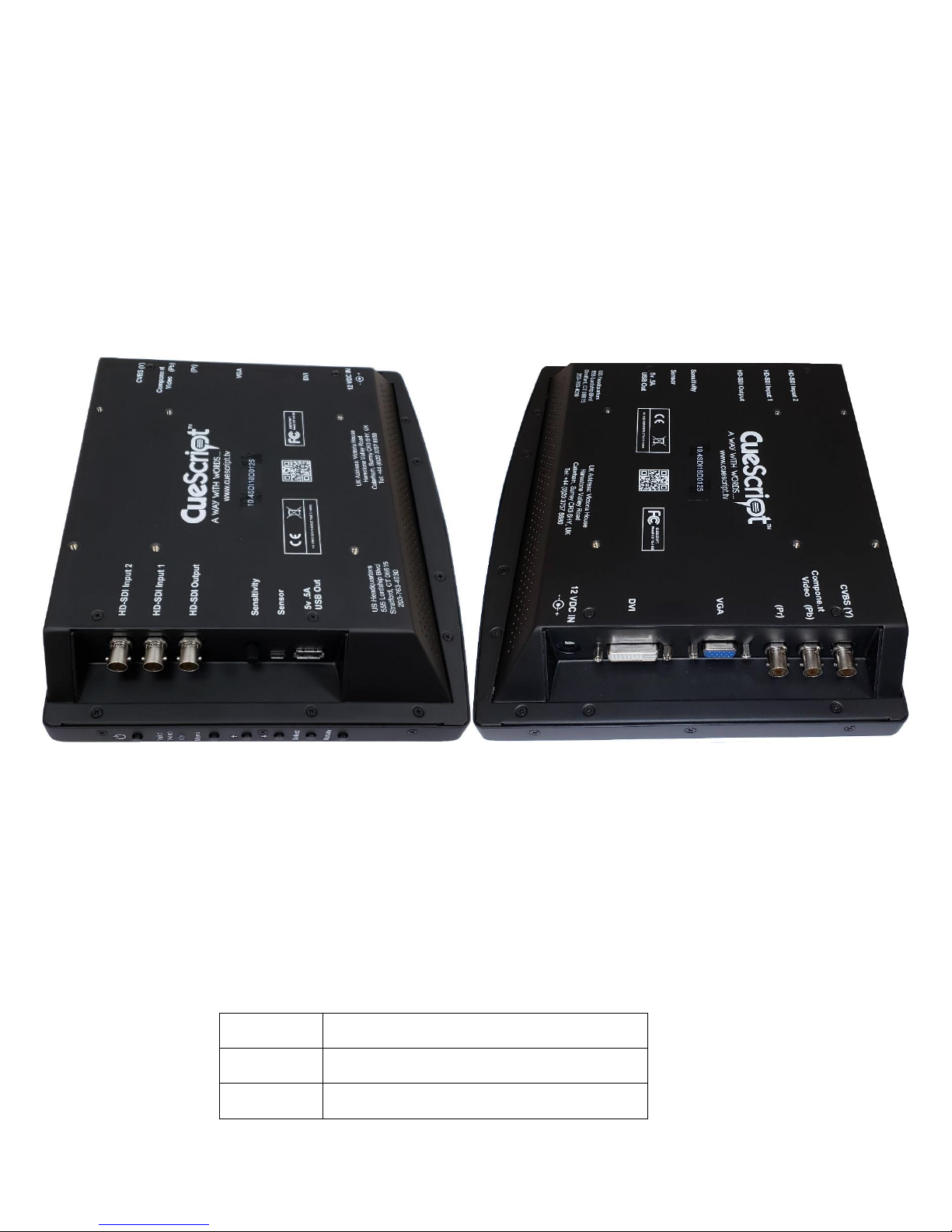
10 Connectors and Controls
10.1 DC Power
The CueScript CSF10 prompters require a regulated source of 12 VDC that should be capable of supplying
approximately 2 amperes. Alternatively, a battery with sufficient capacity may be used.
Prompter Connector type: 2.5mm X 5.5mm Male coaxial plug
Mating (cable) connector: 2.5mm X 5.5mm Female coaxial socket
Pin
Description
Outer Shell
GROUND (connected to monitor chassis)
Center Pin
+12V DC
Page 9
9
Power Consumption Tables
10.2 Composite Video In and Out
Prompter Connector type: 75 Ohm BNC Socket
Mating (source) connector: 75 Ohm BNC Plug
Pin
Description
Center
Composite Video In (PAL,NTSC, or SECAM)
Outer
Ground
10.3 VGA
Description: CueScript CSF10 prompters have a PC compatible VGA input. The prompter
will automatically scale the input resolution to the screen native resolution.
Prompter Connector type: 15 pin High Density D socket
Pin connections are standard VGA.
10.4 SDI
Description: CueScript CSF10 prompters have a two SDI BNC input available. The selected
input (from the menu) will appear on the BNC SDI output connector as well as
the screen. The prompter will automatically scale the input resolution to the
screen native resolution.
Prompter Connector type: Standard DVI to HDMI Connector (not supplied).
10.5 USB Out
Provides a .5A source of 5 VDC to power accessories. Provides Tally signal to Camera Number system.
Prompter Connector type: USB-A (Standard USB)
Mating (cable) connector: USB-A (USB) plug
Pin
Description
1
+5 VDC
2
-Tally Repeat
3
+Tally Repeat
Model CSF10
Power Consumption @ 12 VDC
1.2A DC
14.4 Watts
Page 10
10
4
No Connection
5
Ground
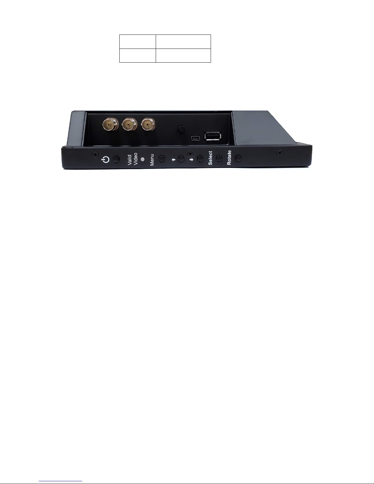
11 Operation
11.1 Control Panel
There are 6 buttons on the right side of the prompter. Each are described below:
11.2 Power Button
Pressing the power button will turn the monitor on. To turn the monitor off, you must press and hold the
power button until the monitor turns off.
11.3 Rotate Button
When the prompter is first turned on, the internal tilt switch will be activated and automatically set the
correct image when mounted either in the front facing position or in the under camera prompting position.
Tilting the prompter back and forth will cause the image to automatically switch the image orientation. This
will continue unless the “Rotate” button is pressed. Once pressed, the image rotation will be in a manual
mode and unaffected by the tilt switch. Only turning off the power and turning it back on will re-activate
the tilt switch.
Pressing the rotate button will cause the screen to “flip” in both the horizontal way and the vertical way for
a total of four possible ways. Successively pressing the rotate button while watching the prompting mirror,
allows for a quick set up for proper operation.
11.4 Menu keys
There is a group of four buttons arranged as Up and Down, and Left and Right, with one button in the
center. The operation of these buttons for the on-screen display is as follows:
MENU
• Activates or deactivates the OSD (On-Screen-Display) menu
• Reverts to one higher level menu page
DOWN ARROW
• Moves the OSD selection DOWN one item
Page 11
11
UP ARROW
• Moves the OSD selection UP one item
RIGHT ARROW (+)
• Increments the OSD item value
• Enters into a OSD sub menu
• Stores the new value entered on the OSD
LEFT ARROW (-)
• Decrements the OSD item value
11.5 Tally Controls
The right side of the prompter has a Sensor jack for a CueScript Tally sensor. A potentiometer is present to
adjust the sensitivity of the tally sensor. The USB output connector is designed to connect with the
CueScript Tally Number system and provide a camera number and tally system within the CSF10 prompter.
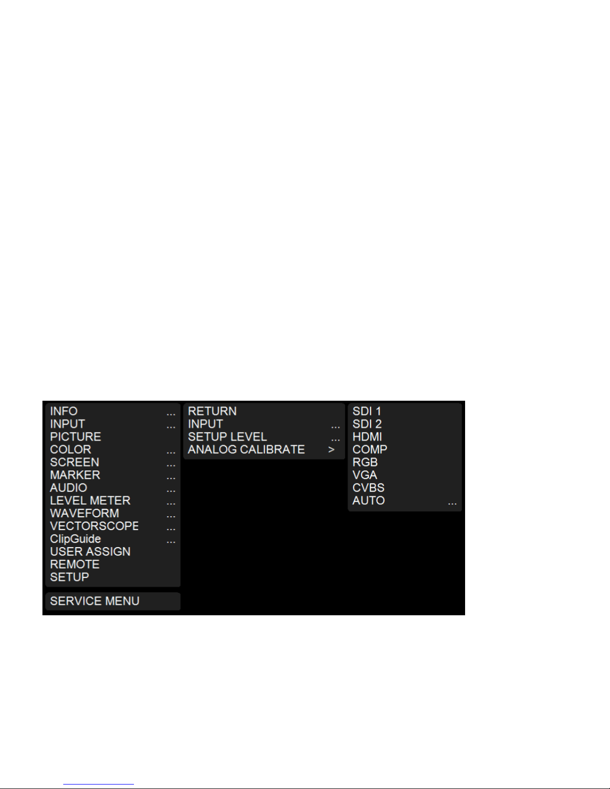
11.6 LCD Controller Menu
12 OSD Menu Layout
Menu consists of 3 level as below from left to right for deeper level.
12.1 To enter next level
Choose Level1 item and press SELECT key to enter Level2 items.
12.2 To exit from current level
Press MENU key or Choose RETURN menu.
Page 12

12
13 INFO Menu
13.1 MODEL
Shows product model name “Venus2 Pro” as default
13.2 INPUT
Shows current selected video input port such as SDI 1 or HDMI
13.3 FORMAT
Shows current detected video format such as 1080/60i
13.4 COLOR TEMP
Shows current selected color temperature such as D65
13.5 RANGE
Shows current digital representation range such as LIMITED or FULL
LIMITED uses 16-235 in 8 bits representation.
FULL uses 0-255 in 8 bits representation.
13.6 VERSION
Shows current firmware version information.
Page 13

13
14 INPUT Menu
14.1 RETURN
Return to Level 1 menu
14.2 INPUT
Selects an input port.
⚫ SDI1: Selects SDI1 Input, SDI Out will be copy of SDI 1
⚫ SDI2: Selects SDI2 Input, SDI Out will be copy of SDI 2
⚫ HDMI: Selects HDMI
⚫ COMP: Use 3 BNC Input as Component input (Y/Pb/Pr)
⚫ RGB: Use 3 BNC Input as RGB input (R/Gs/B)
⚫ VGA: Selects VGA port
⚫ CVBS: Use 1 BNC input as CVBS (NTSC/PAL)
⚫ AUTO: Scans for valid video format on selected ports
14.3 SETUP LEVEL
Choose setup level for CVBS input.
7.5 IRE: Default value for NTSC-M SMPTE 170M Standard
0 IRE: Japanese black level
14.4 ANALOG CALIBRATE
Calibrate ADC with 8 COLOR BARS.
IMPORTANT 8 ColorBars must contain 8th color as BLACK.
Dual confirmation is required to start calibration.
Selects CALIBRATE then move up(or down) and selects for final confirm.
Page 14

14
15 PICTURE
15.1 RETURN
Return to Level 1 menu
15.2 BRIGHT
Changes black level at range of 0 to 100.
Default value is 50 for even black level to LCD panel’s black.
15.3 CONTRAST
Changes video gain at range of 0 to 100.
Default value is 80 for unity gain and maximum dynamic range.
Minimum value 0 shows no video because of gain value at 0.
Maximum value 100 boosts video up with approx. 20% saturation.
15.4 CHROMA
Changes Chroma level at range of 0 to 100.
Default value is 50 for standard color representation.
Minimum value 0 shows video in grayscale.
Maximum value 100 shows boosted color approx. 6dB.
15.5 SHARPNESS
Changes sharpness level at range of 0 to 100.
Default value is 0 for neutral image processing.
15.6 GAMMA
Changes gamma curve at range of 0.45 to 3.00 with 0.05 steps.
Default value is 2.20.
Typical value is between 2.20 and 2.40.
Lower range helps enhancing dark area for easier view.
15.7 RESET TO DEFAULT
Resets only picture related values back to default values.
Other values will not be changed.
Page 15

15
16 COLOR
16.1 RETURN
Return to Level 1 menu
16.2 COLOR TEMP
Selects color temperature for CIE D65 and Japanese D93.
D65 offers preset 6500K for white balance.
D93 offers preset 9300K for white balance.
USER allows manual adjustment for gain and bias.
Default value is CIE D65.
16.3 BIAS
Adjusts black level of LCD panels at range of -50 to +50.
Often used to calibrate lower luminance white balance points.
However, leave it as 0 on all channels are recommended for general practice.
Default value is 0 on all channels.
16.4 GAIN
Adjusts post processing video gain at range of 0 to 255.
Often used to calibrate higher luminance white balance points.
In general, any channels should not exceed 128.
Use only lower than 128 to avoid unnecessary saturation.
E.g. 120/128/124 for R/G/B
Default value is 128 on all channels.
Page 16

16
17 SCREEN
17.1 RETURN
Return to Level 1 menu
17.2 SCAN
⚫ NORMAL
◼ Displays all valid video region.
◼ Also known as JUST SCAN or ZERO SCAN.
⚫ OVERSCAN
◼ Crop and zoom approx. 5%
⚫ ZOOM
◼ Crop and zoom at the center of video input for magnification.
17.3 ASPECT
⚫ AUTO
◼ Maintains original aspect ratio.
◼ Border may appear according to panel’s native aspect ratio.
⚫ 4:3
◼ Forces any video input to 4:3 ratio.
⚫ 16:9
◼ Forces any video input to 16:9 ratio
⚫ FILL
◼ Forces any video stretch to panel’s all valid area.
17.4 MONO/COLOR
⚫ RGB
◼ Displays all three(RGB) channels for normal operation.
⚫ MONO
◼ Displays video in grayscale.
⚫ RED/GREEN/BLUE
◼ Displays only one channel at a time for channel verification.
17.5 FLIP H/FLIP V
Flips image horizontally and vertically.
Page 17

17
18 MARKER
Marker is a utility which helps to find center, perpendicular and aspect ratio.
Marker is hidden when OSD menu is displayed.
Marker is hidden when there is no valid input signal.
18.1 RETURN
Return to Level 1 menu
18.2 MARKER
Enables/Disables marker lines.
18.3 CENTER
Enables/Disables center cross marker.
18.4 ASPECT
Enables/Disables marker for aspect ratio guide line.
⚫ OFF
⚫ 4:3
⚫ 16:9
⚫ 1.85:1
⚫ 2.35:1
⚫ 4:3&1.85:1
⚫ 4:3&2.35:1
18.5 SAFETY
Adjusts margin for safety marker at range from 80% to OFF.
Default value is 80.
Page 18

18
18.6 CROSSHATCH
Enables/Disables crosshatch type markers. Crosshatch marker is used for perpendicular guide.
⚫ OFF(DEFAULT)
⚫ SMALL
⚫ MEDIUM
⚫ LARGE
18.7 MARKER MAT
Choose background type when marker is enabled.
⚫ CLEAR(DEFAULT) background is clear
⚫ HALFTONE background is half transparent.
⚫ BLACK background is opaque black.
18.8 LINE THICKNESS
Controls thickness of markers at range from 1 to 3.
[Thin] 1 to 3 [Thick]
Default value is 1 [Thinnest].
19 AUDIO
Controls volume for an external speaker if available.
19.1 RETURN
Return to Level 1 menu
19.2 FRONT VOLUME
Default Volume is 50.
19.3 REAR VOLUME(Optional)
Default Volume is 50.
20 LEVEL METER
20.1 What is Audio a Level Meter?
SDI signal can carry embedded audio along video signal.
Often confirmation of audio signal presence is required for various reasons.
Audio level meter offers not only the presence of audio signal but it also displays precisely measured level
in dBFS (Decibel in Full Scale).
Venus2 Pro displays audio channel 1 on left and channel 2 on right.
20.2 LEVEL METER
Enables/Disables Audio Level Meter for embedded audio from SDI inputs.
Page 19
19
21 WAVEFORM
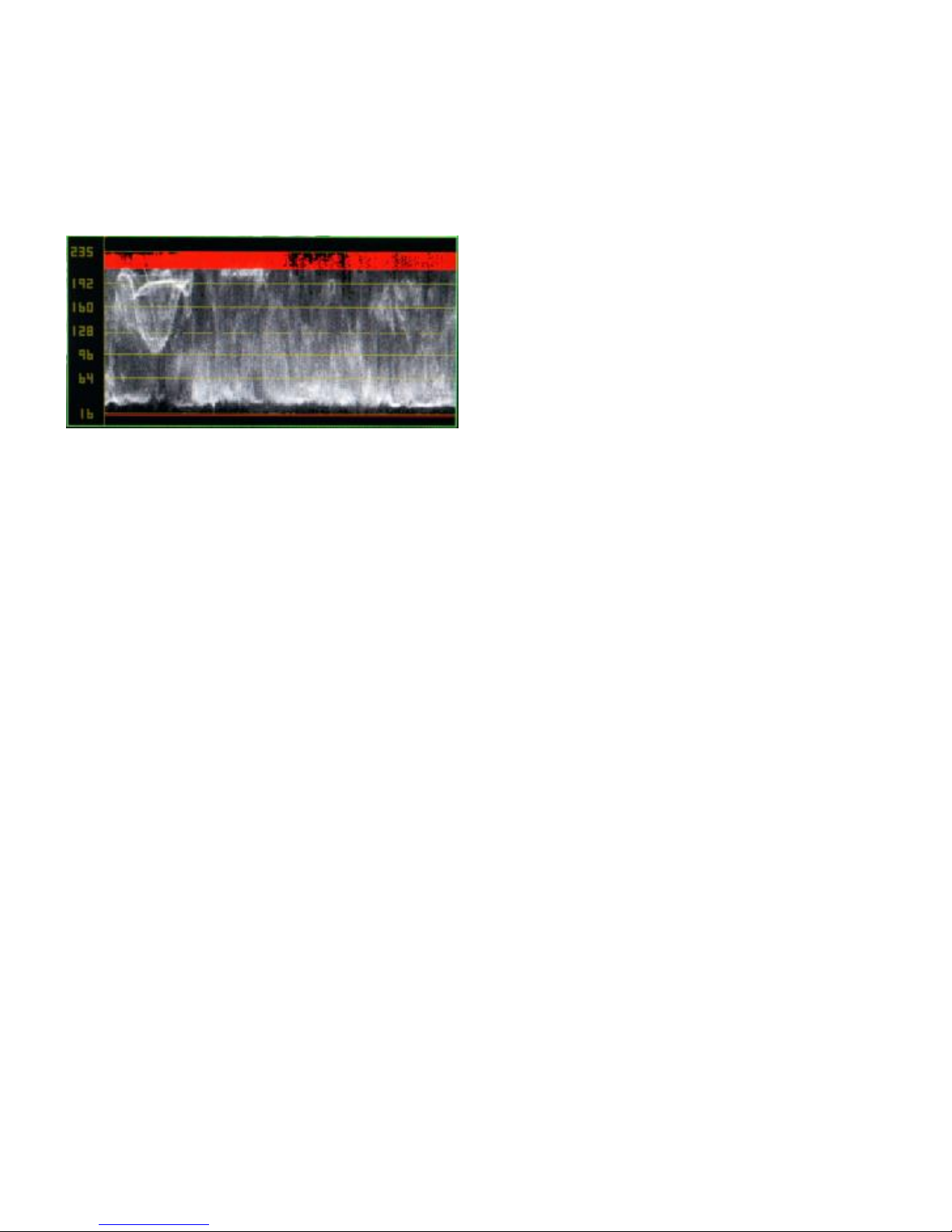
21.1 What is a Waveform Monitor?
To prevent accidental over exposure (or saturation), engineers need to verify valid range of dynamic range.
Waveform monitor helps engineer to determine dynamic range of input signal. It also helps to adjust optical
focus on camera shooting.
21.2 RETURN
Return to Level 1 menu
21.3 WAVEFORM
Enables/Disables Waveform monitor for video analysis from SDI inputs.
Page 20
20
22 VECTORSCOPE
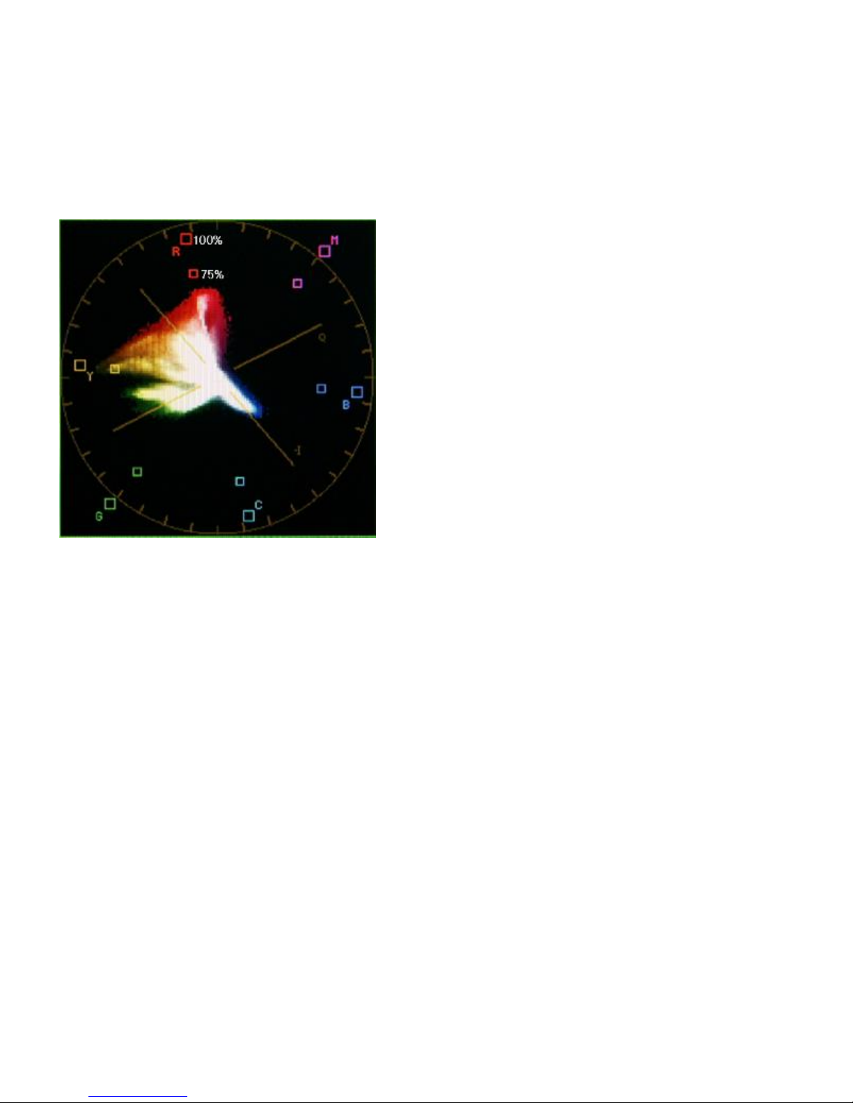
22.1 What is a Vector Scope?
Conventional TV system limits color reproduction range due to limitation of technical reasons like
bandwidth and interference over RF transmit.
VectorScope is designed to verify chrominance range over the content in real time.
22.2 RETURN
Return to Level 1 menu
22.3 VECTORSCOPE
Enables/Disables VectorScope for video analysis from SDI inputs.
Page 21

21
23 ClipGuide
Monitor input video range on luminance and chrominance to avoid accidental clipping or saturation. This
feature is also known as Zebra but ClipGuide is more enhanced with color and lower/upper thresholds.
23.1 RETURN
Return to Level 1 menu
23.2 CLIPGUIDE
Enables/Disables ClipGuide feature.
23.3 MODE
⚫ LUMA[Y]
◼ Apply ClipGuide on luminance(Y) channel only
⚫ Y ON MONO
◼ Apply ClipGuide on luminance(Y) channel only
◼ Displays original video content in grayscale for better identification.
⚫ CHROMA
◼ Apply ClipGuide on chrominance channel only
⚫ C ON MONO
◼ Apply ClipGuide on chrominance channel only
◼ Displays original video content in grayscale for better identification.
⚫ Y & C
◼ Use both Luminance and Chrominance.
⚫ Y & C ON MONO
◼ Use both Luminance and Chrominance.
◼ Displays original video content in grayscale for better identification.
23.4 Y UPPER LIMIT
Sets threshold at range of -7.3 to 109.1 in IRE representation.
Default value is 103.2 in IRE representation.
23.5 Y LOWER LIMIT
Sets threshold at range of -7.3 to 109.1 in IRE representation.
Default value is -0.9 in IRE representation.
23.6 C UPPER LIMIT
Sets upper threshold at range of 0 to 255 in 8 bits digital representation.
Default value is 240 in 8bpp representation.
23.7 C LOWER LIMIT
Sets lower threshold at range of 0 to 255 in 8 bits digital representation.
Default value is 16 in 8bpp representation.
Page 22

22
24 USER ASSIGN
Sets user selected feature as a hotkey for specific features.
24.1 RETURN
Return to Level 1 menu
24.2 Available Options
24.2.1 INPUTS
SDI1/SDI2/CVBS/HDMI/RGB/VGA/COMPONENT
24.2.2 Screen Modes
Rotates available options of each feature.
⚫ MONO
⚫ COLOR
⚫ CHANNEL
24.2.3 Screen Modes
Rotates available options of each feature.
⚫ SCAN
⚫ ASPECT
⚫ ZOOM
24.2.4 Utility
Enables/Disables each feature.
⚫ MARKER
⚫ AUDIO METER
⚫ WAVEFORM MON
⚫ VECTORSCOPE
⚫ ClipGuide
⚫ TIMECODE
24.2.5 Audio
Mutes/Unmutes audio output
⚫ AUDIO MUTE
Page 23

23
25 SETUP
25.1 RETURN
Return to Level 1 menu
25.2 FORMAT DISPLAY
⚫ AUTO – Displays detected video format approx. 5 sec.
⚫ ON – Displays detected video format always.
⚫ OFF- Does not display detected video format.
Default value is AUTO.
25.3 TIMECODE
Enables/Disables TIMECODE from SDI signal.
⚫ OFF – Does not display timecode from SDI.
⚫ LTC – Displays LTC from SDI ANC.
⚫ VITC1/VITC2 - Displays VITC1 or VITC2 from SDI ANC.
Default value is OFF.
25.4 USERBIT
Enables/Disables Userbit from SDI
25.5 PICTURE DELAY
⚫ NORMAL – Enables all video enhancement processing for optimum quality.
⚫ FAST – Reduces some video processing for faster picture response.
Default value is NORMAL.
25.6 POWER SAVE
Enables/Disables power consumption control when there is no valid video signal.
⚫ ALWAYS ON – Does not control power saving.
⚫ OTHER – Waits for selected period until it goes to sleep.
Default value is ALWAYS ON.
Wakes up at any key input or valid video input signal.
25.7 KEY LOCK
Prohibits OSD key operation except MENU key.
25.8 BACKLIGHT
Controls backlight at range from 0 to 100%.
Default value is 80%.
25.9 OSD ALPHA
Controls transparency of OSD menu at rage from 0 to 6.
[Opaque] 0 ~ 6 [Transparent]
Default value is 0.
Page 24

24
25.10 RESET TO DEFAULT
Restores all setting back to factory standard.
Requires dual confirmation.
25.11 BACKUP USER CONFIG
Backs up current setting at where it can be retrieved later.
25.12 RESTORE USER CONFIG
Restores backed up setting from where user saved for the last time
26 EMC Compliance
The CueScript CSF10 series prompter monitors have been tested by TUV Rhineland and are compliant with
the following standards:
Guidance Documents:
Emissions: EN55103-1:1996
Immunity: EN55103-2:1996
Test Methods:
Emissions: EN55022:2010 & FCC Part 15
EN61000-3-2:2006 +A1:2009 +A2:2009, EN61000-3-3:2013
Immunity: EN55024:2010,
EN61000-4-2:2009, EN61000-4-3:2006 + A2:2010,
EN61000-4-4:2012, EN61000-4-5:2006, EN61000-4-6:2009,
EN61000-4-8:2010, EN61000-4-11:2004
Meet requirements for VCCI 2010. (Japan)
27 CE Declaration
The CueScript CSF10 prompter monitors are compliant with all applicable directives necessary for
declaration of conformity. All models are RoHS compliant and all models are have the CE mark affixed.
28 SAFETY INFORMATION
The CueScript model CSF10-SDI prompter monitors are not user serviceable. Please return to CueScript in
the event that servicing is required. After any servicing, the CueScript service center will re-test each
prompter to ensure product safety is intact.
In no event should any modification be made to any CueScript prompter without authorization from
CueScript. Doing so without authorization will void the warranty and possibly affect the safety of the
product.
Page 25
25
Notes:
________________________________________________________________________________________
________________________________________________________________________________________
________________________________________________________________________________________
________________________________________________________________________________________
________________________________________________________________________________________
________________________________________________________________________________________
________________________________________________________________________________________
________________________________________________________________________________________
________________________________________________________________________________________
________________________________________________________________________________________
________________________________________________________________________________________
________________________________________________________________________________________
________________________________________________________________________________________
________________________________________________________________________________________
________________________________________________________________________________________
________________________________________________________________________________________
________________________________________________________________________________________
________________________________________________________________________________________
________________________________________________________________________________________
________________________________________________________________________________________
________________________________________________________________________________________
________________________________________________________________________________________
________________________________________________________________________________________
________________________________________________________________________________________
________________________________________________________________________________________
 Loading...