

Page 1
CUDA 2848
A
TTENTION
USE ONL
Y CUD
A APP
R
O
VED
DETERGENTS
T
O EXTEND
LABOR
W
ARRANTY
T
O 1-YEAR!
MIX DETERGENTS 1 LB (1/2 KG) PER
5-GALLONS (15 LITERS) OF
W
A
TER
For CUD
A App
ro
ved Dete
r
g
ents visit
http://ww
w
.cudausa.com or
call 888-319-0882
9.807-513.0
90-DAY LABOR WARRANTY
EXTENDS TO 1-YEAR
WITH EXCLUSIVE USE OF
CUDA DETERGENTS
LIMITED
This
is
a
heated
pa
r
ts
c
leane
r
.
Use
on
l
y
nonflamma
b
l
e
,
non-
co
m
b
ustib
l
e
,
wate
r
-based
c
leaning
compounds
in
this
ma
c
h
in
e
.
Do
n
ot
fill
or
contaminate
with
an
y
flamma
b
le
o
r
com
b
u
stib
l
e
materia
l
su
c
h
as
gasolin
e,
al
c
ohol
,
mineral
spirits
, etc
.
Drain
pa
r
ts
to
be
c
leaned
of
a
n
y
com
b
u
sti
b
le
or
flamm
a
b
le
material
be
f
ore
placing
i
nside
cabinet
.
F
ailure
to
obse
r
ve
t
h
is
warning
will
creat
e
an
e
xtreme
l
y
haza
r
dous condition
.
Este
es
un
limpiad
or
de
pa
r
tes
que
se
calienta
.
Util
i
c
e
sola
-
mente
en
esta
máquina
compon
entes
de
li
mpiez
a
base
a
gua
,
no
inflama
b
le
s
y
no
com
b
us
ti
b
les
.
N
o
llenar
o
contam
inar
con
algún
material
inflama
b
le
como
,
gaso
lina
,
alcohol
,
esencias
m
inerales,
et
c. Drene las
pa
r
tes a ser limpiadas de cu
a
lquie
r com
b
usti
b
le o
material
inflama
b
le
an
tes
de
in
tr
odu
c
ir
en
el
gabinet
e
.
Si
descuida
obse
r
v
ar
estas
precauciones
,
pueden
crea
r
se
c
ondici
o
-
nes
extremada
mente pelig
r
o
sas
.
Ce
nett
o
y
eur
de
pièces
est
c
h
auffé
.
Utiliser
dans
cet
a
pparei
l
seulement
des
n
e
t
t
o
y
eu
r
s
à
base
d
’eau
,
non
com
b
usti
b
l
es
et
non
in
flammab
l
es
.
N
e
pas
y
ajouter
o
u
contaminer
a
vec
des
matériaux
com
b
usti
b
les
tels
:
gasolin
e
,
alcool
,
etc
.
Vider
les
p
ièces
conten
a
nt
des
ma
téria
ux
com
b
usti
b
l
e
s
ou
inflamma
b
les
a
van
t
de
le
s
placer
à
l’intérieur
d
u
cabinet
.
Ne
pas
obse
r
ver
ces
ave
r
tissements
peut
créer des si
tuations risquée
s
.
H
O
T
W
A
TER
Be
f
ore op
ening lid
,
wait 5
seconds to all
o
w spr
a
y
arm/turnta
b
le to stop
spinning.
A
G
UA
CALIENTE
Antes de abrir la tapa
,
espere 5 segundos pa
ra
que la barr
a
r
otatoria se
detenga.
EA
U
CH
A
UDE
A
v
ant d’ouvrir
le couve
r
t,
attendez 5
s
e
condes
pour
permettre au
bras
v
ap
orisa
-
teur/plaque tournante
d’arrêter
de tourne
r
.
WARNING
PRECA
UCION
/
A
D
VE
RTISSEMENT
CA
UTION
CUI
D
ADO /
A
TTENTION
OPER
A
TING INST
RUCTIONS
INST
R
UCCIONESDE OPER
A
CION
INSTRUCTIONS D’OP
É
R
A
TIO
N
IMPO
R
T
AN
T
:
Be
f
ore op
e
rating th
i
s
m
a
chin
e
,
complet
e
ly
f
a
mi
l
i
a
r
i
z
e
y
ourself with inst
r
u
cti
on
ma
nual pr
ov
ided
.
On
l
y auth
o
r
i
z
ed and
prope
r
ly
inst
r
uc
t
ed ind
i
viduals
s
h
ould o
p
e
r
ate this machin
e.
Bef
ore loading pa
r
ts onto t
u
r
nt
a
b
le/ b
as
k
et, be cer
-
ta
in
the pump is off and not
r
unning and
the
w
ash
solutio
n
s a
re at op
e
r
ating tempe
ra
tur
e
.
1
.
F
ill tank
w
ith
w
ater and cleaning solution
.
W
at
e
r l
e
v
e
l
should b
e 2" below
t
he acces
s door
s
.
Ch
e
c
k da
i
l
y
.
2
.
Pro
g
r
a
m heater timer
f
or d
esi
red pe
r
iod of
ope
r
ation
.
All
o
w t
ime
f
or un
i
t
to
p
reheat cleaning
solution
.
3.
Open door
/l
id
and
place ar
ticles to be clean onto
bas
k
et
/t
u
r
nta
b
l
e
.
Be ce
r
tain no pa
r
ts
prot
r
ude
throu
gh the
b
ot
tom or b
ey
ond the sides of th
e
bas
k
et/tu
r
nta
b
le
.
Do not
e
xceed the sp
ecified
heigh
t
or
w
eight limit
f
or this s
p
ra
y
w
ash
cabi
n
et.
4
.
Close door/lid and la
t
ch se
c
urel
y
.
With machine
set
to
w
ash, tur
n
“
w
ash cycle
”
ti
mer
to
the desi
r
ed
clea
ning tim
e.
Pump will sta
r
t
a
n
d
r
un until time
has
e
xpired.
5.
Bef
ore opening the
do
o
r/l
id, tu
r
n
w
ash cycle timer
off an
d
w
ai
t
5
sec
on
ds f
or machine to stop spin
-
ning
.
This w
i
l
l
al
l
ow stea
m
to e
sc
ape t
he cabinet
and
e
x
ce
s
s
w
ater to d
r
ain fro
m
y
our pa
r
t
s
.
IMPO
R
T
ANTE:
Antes de opa
r
ar e
l
equip
o,
f
amiliarícese com
-
pletamente con el ma
n
u
a
l de ope
ració
n
que se inclu
y
e
.
Solo
p
e
r
sonal
a
uto
r
izado y de
bidamente capaci
tad
o debe
opa
rar
éste equip
o
.
A
n
te
s
d
e
a
b
r
ir
l
a pue
r
ta
/
cu
b
ie
r
t
a
o l
as piezas de
carga
sobre la to
r
n
a
mes
a
/canast
a
, a
s
eg
úrese de q
u
e la b
o
mba
es
t
é apagada y sin funcio
na
r
, y q
ue
la
s soluci
o
nes
de limpiez
a
estén
a tempe
r
atu
r
a
de
f
un
c
ionamient
o
.
1
.
Ll
e
ne
el depósito con
agua y la s
olución pa
r
a limpi
eza
. E
l
n
i
v
el de
l agua
d
ebe est
a
r 2" por debajo de l
as pue
r
ta de ac
-
ceso
.
V
e
r
ifi
qu
e
el
ni
v
el dia
r
iamente
.
2
. Pro
gr
am
e
el
T
em
p
o
r
iz
a
do
r
d
el calentador pa
r
a el período de
ope
r
ació
n
de
s
e
a
d
o
. Deje pa
sar un tiempo pa
r
a
que la
uni
d
a
d
precalie
n
te la s
olución pa
r
a limpie
za.
3
.
A
b
ra la pue
r
ta/tap
a
y coloque las piezas a l
a
v
ar en la tor
-
na
m
esa/canasta, ase
g
úrese
de que ninguna pieza so
-
brepase el f
o
ndo
ni el períme
t
ro de la to
r
namesa
.
No
e
x
ceda
l
o
s limites especificados de pe
so y altu
r
a pa
ra
el gabinete
de
la
v
ad
o
.
4.
Cierre la
pue
r
ta/tapa y a
s
egure el
can
dad
o
.
C
o
n la máq
ui
n
a
en posición de l
a
v
a
r
, aj
uste el tempo
r
izador
de
“ciclo de
la
v
ado
”
al t
i
e
mpo desead
o
. L
a bomba
ar
r
a
ncará y func
i
onará
du
r
a
nte el tiempo seleccionad
o
.
5
.
Antes de
ab
r
ir la pue
r
ta/
cubie
r
ta, apague e
l
tempo
r
izador del
ciclo de l
av
a
do y e
s
p
ere 5 segundos pa
r
a que la máquina
deje de
gi
ra
r
.
Esto
pe
r
mitirá que el
v
apor salga del gabinete
y
el
e
xceso de agua drene
de la
s
p
ieza
s
.
IMPO
R
T
A
NT
:
A
v
a
nt d’ut
i
l
iser
c
e
tt
e machin
e
,
f
amilia
r
isez
-
v
ous
co
m
plètement
a
v
ec
l
e ma
n
uel d’
inst
r
ucti
on
f
our
ni
. Cette
mach
in
e d
e
v
r
ait être utilisée
s
eulement pa
r du personnel
a
uto
r
isé e
t
f
or
mé
.
A
v
ant l’ou
v
e
r
ture de la po
r
te/du c
o
u
v
e
rcle
o
u du charge
men
t des pièces sur la ta
b
le t
ou
r
nante
/l
e pa
nie
r
,
s’assurer que la pom
pe est en position arrêt et
n
e
f
oncti
on
ne
pas et que les solutions
de l
a
v
age sont à tempé
r
ature
de
f
o
nctionnement
.
1
.
Remplir le rése
r
v
oir d’ea
u
et
d’une
solution de nett
o
y
ag
e
.
Le ni
v
eau d’eau doit se t
rouv
er à 5
cm (2 po) sous
les
po
r
tes d’
accè
s
.
Vé
r
ifier quotidiennement.
2
.
Prog
r
a
mmer le mi
n
ute
r
ie de chauf
f
age de l’appareil pour
la pé
r
iod
e de
f
onctionnement souhaité
e
.
Pré
v
oir du temps
pour
qu
e l’a
ppareil préchauff
e la s
olutio
n de nett
o
y
ag
e
.
3
.
O
uv
r
i
r
l
a po
r
t
e
/cou
v
e
r
t e
t placez
l
es a
r
ticles à
ê
tre l
a
vé
sur le
panier/pl
a
que tou
r
nan
t
e
.
Assurez-
v
ou
s qu’il n’y est
aucune pièce dépassant
le painer ou dans le
f
ond au-delà
du painer/plaq
u
e tou
r
nant
e
.
4.
F
e
r
m
ez la po
r
te/cou
v
e
r
t et
v
errouillez de
f
a
ç
on sécu
r
itair
e
.
La ma
c
hine prête po
u
r le l
av
ag
e
, tour
nez le
m
i
n
uteur
“
w
ash
cycle
”
a
u
temp
s
de la l
a
v
age désiré.
La pompe
f
onctionne
r
a
jusqu’à
c
e que temps sélectionné
soit écoulé.
5
.
A
v
ant d’ou
v
r
ir la po
r
te/le c
ou
v
ercl
e
, mettre la mi
n
u
te
r
i
e
du
cycle de l
a
v
ag
e à l’ar
rêt et at
t
e
ndre pendant 5 secon
d
e
s
que
l
’appareil s
’a
r
r
ête de to
u
r
ne
r
.
Cela pe
r
mett
r
a à la
v
apeur de
s’échapper du cabinet et à l’
e
xcès d’eau
de
s’écouler de
v
os
pièce
s
.
WARNING
PRECA
UCION
/
A
D
VE
R
TISSEMENT
•
Ma
c
hine m
ust be connect
ed
to a p
r
oper
l
y si
z
e
d
lo
c
kab
le disconnect.
•
Installation
m
ust comp
l
y with NEC code
.
•
For supp
l
y connection
,
use w
ires accepta
ble
f
or
at least 90
degrees
C.
•
Do not use bel
o
w grade floor or grade l
e
vel.
T
h
e
f
oll
o
w
i
n
g
s
c
he
d
u
l
e
is ba
s
e
d
on a
v
e
r
a
g
e
us
e
.
Hi
g
he
r
u
sa
g
e
m
a
y req
u
i
r
e mo
re
freq
u
en
t
m
a
int
e
-
na
n
c
e.
I
MPO
R
T
ANT
:
Be sur
e
e
l
e
ctr
ical supply is OFF be
-
f
ore d
r
aining sum
p
. O
nl
y
qua
li
fied p
e
rsonnel should
se
r
vice this machin
e
.
D
AIL
Y
:
•
Che
c
k
w
ater l
e
v
el in the sump dail
y
. T
opping
off the
w
ater dai
ly wi
ll pr
e
v
ent damage to the
heate
r element.
•
Rem
o
v
e and clean deb
r
is sc
reen.
•
Visually che
c
k
f
or plugged nozzle
s
. Rem
ov
e
and clean if needed
. Reinsta
ll in the
e
xact o
r
igi
-
n
al position.
WEEKL
Y
:
•
G
r
ease/oil door
hinge
s
.
M
ONTHL
Y
:
•
P
e
r
f
o
r
m
v
i
s
u
a
l
che
c
k o
f
t
u
r
nt
a
b
l
e d
r
i
v
e
c
h
a
i
n
.
•
D
rain
w
ash solution from sum
p
, rem
ov
e s
a
nd/
gr
it from bo
ttom of the sum
p
.
C
a
re should be
ta
k
en
to
av
oi
d bending
or
d
a
maging heater ele
-
ment du
r
ing the cle
aning proces
s
.
•
When sump h
a
s been cleaned and refilled with
w
ate
r
,
add t
h
e
reco
mmended q
uant
ity of deter
-
g
ent
f
or
y
o
ur machin
e.
N
O
TE
:
D
is
sol
v
e cleaning
p
o
w
d
er into
w
a
r
m w
a
t
er
be
f
ore adding the ma
n
u
f
acturer
’
s recommended
amount to the tank.
8.922
-
402.0
•
La máquina debe estar conectada a un
en
c
hu
f
e
eléctrico de seg
u
ri
dad
.
•
La instalación debe cu
mplir
co
n el código NEC.
•
P
ara l
a
s con
e
xiones de alimentación
,
use ca
b
le
a
-
do
para al menos 90 grado
s centígrados.
No ut
ilice por debajo del niv
el
del p
iso.
•
L
’
appareil doi
t
être connecté à un
sectionneur
ver
r
o
uilla
b
le de taille
appr
oprié
e
.
•
L
’in
stallat
io
n
doit
se con
former au code
N
E
C
.
•
P
our le
racco
r
demen
t
de l
’alimen
tation
,
u
tilise
r des
fi
ls po
u
v
an
t accep
ter au moins 90 degrés Ce
lsius
.
Ne p
a
s utiliser un calibre ou un grade
inférieu
r
.
Le ta
b
leau sui
v
ant
e
s
t
f
o
ndé sur une utilisation
m
o
y
enn
e
.
U
ne uti
lisation plus impo
r
t
a
nte peut
e
xiger un en
tretien plu
s
fréquent.
IMPO
R
TANT
:
S’assurer que le système élect
r
ique est à l’arrêt
a
v
ant de vider le rése
r
v
o
i
r
.
Seul
l
e
p
ersonne
l qua
lifié doit ré
-
p
are
r
cet appareil.
Q
U
O
TIDIENNEMEN
T
:
•
Vér
ifi
er quotidiennement le ni
v
eau d’eau dans le
rés-
e
r
v
oi
r
.
Le rempl
issage quotidie
n
d’eau pe
r
m
e
t
d
’
éviter
d’endom
m
a
ger
l’élément chau
f
f
ant.
•
Démonter
e
t nett
o
y
er le fil
t
re à dé
b
r
i
s
.
•
Vé
r
ifier visuellement si des
bus
es sont bo
uchées/ob
-
st
r
u
é
e
s
.
Démonter et n
et
to
y
e
r
, le cas échéant.
Réinstaller
dans l
a
po
sition initiale
e
xact
e
.
HEBDOMADAIREMEN
T
:
•
G
r
aisser/huiler les pentures/cha
r
nières d
e la po
r
t
e
.
M
ENSUELLEMEN
T
:
•
P
r
océder à un
cont
rôle
visuel de la
chaîne d’ent
r
aîne
m
ent
de la ta
b
le tou
r
nante
.
•
Assécher la solution d
e l
av
a
g
e du rése
r
v
o
i
r
,
et enl
e
v
er tout
sa
b
le/
g
r
a
vier se trou
v
ant a
u
f
ond
.
Des préc
autions d
o
i
v
ent
être p
r
ises pour éviter de plier/courber l’élément
c
hauf
f
ant
ou de l’endommager au cours du processus de nett
o
y
ag
e
.
•
L
ors
q
ue
l
e
ré
s
e
r
vo
i
r
a
ét
é
n
et
t
o
yé
e
t
r
e
m
pli
d
’e
a
u,
ajo
u
t
e
r
l
a
q
u
a
n
ti
té
de
d
é
t
erg
e
n
t
r
e
c
o
m
m
an
d
é
e
p
o
u
r
vo
t
re
a
p
p
a
r
e
il
.
N
O
TE:
Bien dissoud
re
la poudre
dans l’eau chaude
avant
d
’
aj
outer dans le rés
e
r
v
oi
r
.
El
pl
an
d
e
ma
nt
e
n
imi
en
t
o
que
se
p
r
es
e
nt
a
a
co
n
t
i
n
ua
ción, est
á
b
a
s
a
do
e
n
u
n
u
s
o
p
r
o
m
ed
io
d
e
l
e
qu
i
po
.
Un
uso m
á
s fr
ec
ue
n
t
e
o
s
e
v
e
r
o
p
u
e
d
e r
e
q
u
e
r
i
r
u
n
m
an
t
en
i
m
i
ent
o
m
ás
f
re
cu
e
nt
e
.
IMPO
R
T
ANT
E
:
Asegúrese de que el sistema eléct
r
i
co
esté
A
P
A
GADO antes de
v
aciar el cá
r
te
r
.
Sólo
personal califi
cad
o
deb
e
re
pa
r
ar esta máquina.
DIARIAMENTE
:
•
Comp
r
uebe el ni
v
el del ag
ua en e
l cá
r
ter dia
r
iament
e
.
M
a
ntener e
l
ni
v
el ade
c
uado del agua
e
vitará
dañar e
l
elem
e
nto del c
alen
tado
r
.
•
Retire y limpie los residuos de la c
r
iba.
•
Comp
r
uebe visualmente que las boq
uilla
s
están i
ns
t
aladas
correctament
e
.
Retire y limpie si es ne
c
es
a
r
i
o
.
Reinstale en
la
p
os
ici
ó
n o
r
iginal
e
xacta.
SEMANAL
M
EN
T
E
:
•
Lubr
ique las bisa
g
ras de la pue
r
ta.
M
E
NS
U
A
LMEN
T
E
:
•
Realice una
v
er
ificaci
ó
n visual de la cad
ena de propulsión
d
e
l
a to
r
namesa.
•
Drene
la soluci
ó
n
de limpieza
de
l cá
r
te
r
, retire
del
f
ondo de
cá
r
ter los s
ediment
o
s
. Debe tener cuidado
de
n
o do
b
lar o
d
añar
el elemento del calentador du
r
ant
e
el proceso de
limpieza.
•
Una
v
ez que
el cá
r
ter
e
s
t
á limpio y relleno de agua,
a
gregue
la cantidad recome
ndada de deter
g
e
nte pa
r
a la
m
áquina
.
N
O
T
A:
D
i
s
u
e
l
va
e
l d
e
t
e
rg
e
n
t
e e
n
ag
u
a
c
a
l
i
en
t
e
a
nt
es
de a
g
re
g
a
r
-
lo
a
l
t
a
n
qu
e
en
la
can
tid
a
d rec
ome
n
d
a
d
a
p
o
r el f
ab
r
i
c
a
n
t
e
.
MA
I
N
T
E
NANC
E
INST
R
UCTIONS
I
NS
T
R
UCC
I
ONES
DE
M
ANT
EN
IMI
EN
TO
DIRECTIVES D’ENTRETIEN
Operator’ s Manual
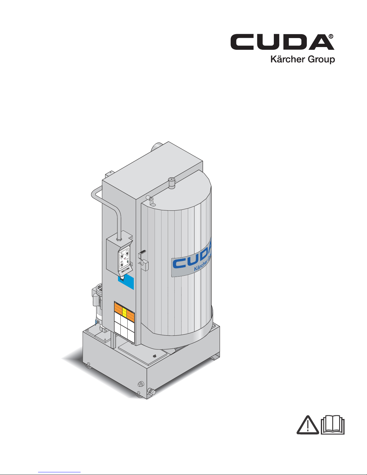
Automatic Parts Washer
Front-Load
MODELS: 1.043-394.0
1.043-421.0
1.043-422.0
1.043-423.0
1.043-424.0
1.043-425.0
1.043-480.0
1.043-481.0
1.043-482.0
1.043-483.0
1.043-484.0
1.043-485.0
For the Cuda Dealer nearest you,
consult our web page at
www.CudaUSA.com
8.930-369.0-AG 05/04/17
Page 2
Machine Data Label
2 CUDA 2848 Operator’s Manual 8.930 -369.0 - AG
Page 3

Table of Contents
Machine Data Label. . . . . . . . . . . . . . . . . . . . . . . . . .2
Table of Contents . . . . . . . . . . . . . . . . . . . . . . . . . . .3
How To Use This Manual . . . . . . . . . . . . . . . . . . . . .4
Safety
Introduction & Safety Information . . . . . . . . . . . . . . .5
General Safety Information. . . . . . . . . . . . . . . . . . . .6
Operations
Component Identification . . . . . . . . . . . . . . . . . . . . .8
Rear View . . . . . . . . . . . . . . . . . . . . . . . . . . . . . . . . .9
Component Identification . . . . . . . . . . . . . . . . . . . .10
Installation . . . . . . . . . . . . . . . . . . . . . . . . . . . . . . . .11
Before You Begin . . . . . . . . . . . . . . . . . . . . . . . . . .11
Step 1: Make Electrical Connections . . . . . . . . . . .11
Step 2: Configure The 24-hour, 7-day Timers
(Optional) . . . . . . . . . . . . . . . . . . . . . . . . . . . . . .11
Step 3: Connect A Compressed-air Line And
Accessories. . . . . . . . . . . . . . . . . . . . . . . . . . . . .11
Step 4: Connect A Water Line . . . . . . . . . . . . . . . .12
Step 5: Fill The Machine With Water And Add
Detergent . . . . . . . . . . . . . . . . . . . . . . . . . . . . . .12
Main Operating Components . . . . . . . . . . . . . . . . .13
Control Panel . . . . . . . . . . . . . . . . . . . . . . . . . . . . .13
Heater Control. . . . . . . . . . . . . . . . . . . . . . . . . . . . .13
Wash Cycle Control . . . . . . . . . . . . . . . . . . . . . . . .13
Skimmer Control. . . . . . . . . . . . . . . . . . . . . . . . . . .13
Turntable Switch . . . . . . . . . . . . . . . . . . . . . . . . . . .13
24-hour, 7-day Timers. . . . . . . . . . . . . . . . . . . . . . .13
Thermostat . . . . . . . . . . . . . . . . . . . . . . . . . . . . . . .13
Adjusting the Thermostat . . . . . . . . . . . . . . . . . . . .13
Adjusting the Safety Switch . . . . . . . . . . . . . . . . . .14
Debris Screen. . . . . . . . . . . . . . . . . . . . . . . . . . . . .14
Air Flow Valve (Optional) . . . . . . . . . . . . . . . . . . . .14
Detail Tray. . . . . . . . . . . . . . . . . . . . . . . . . . . . . . . .15
Detail Sump . . . . . . . . . . . . . . . . . . . . . . . . . . . . . .15
Power Brush (Optional). . . . . . . . . . . . . . . . . . . . . .15
Detail Brush and Flow Regulator . . . . . . . . . . . . . .15
Adjusting the Flow of Cleaning Solution . . . . . . . . .15
Oil Skimmer . . . . . . . . . . . . . . . . . . . . . . . . . . . . . .16
Water Level. . . . . . . . . . . . . . . . . . . . . . . . . . . . . . .16
Automatic Water Fill (Optional). . . . . . . . . . . . . . . .16
Low Water Shut-off. . . . . . . . . . . . . . . . . . . . . . . . .16
Filtration System (Optional) . . . . . . . . . . . . . . . . . .17
Sump Sweep System (Optional). . . . . . . . . . . . . . .17
Detergents And Additives . . . . . . . . . . . . . . . . . . . .17
Rust Inhibitor Additive. . . . . . . . . . . . . . . . . . . . . . .18
Preparing The Machine For Use. . . . . . . . . . . . . . .18
Washing Parts. . . . . . . . . . . . . . . . . . . . . . . . . . . . .18
Shutting Down The Machine. . . . . . . . . . . . . . . . . .18
Maintenance
Maintaining The Machine . . . . . . . . . . . . . . . . . . . .19
Daily Maintenance . . . . . . . . . . . . . . . . . . . . . . . . .19
Weekly Maintenance. . . . . . . . . . . . . . . . . . . . . . . .19
Monthly Maintenance . . . . . . . . . . . . . . . . . . . . . . .19
Semi-Annual Maintenance . . . . . . . . . . . . . . . . . . .19
Cleaning and Aligning the Spray Nozzles. . . . . . . .20
Using the Oil Skimmer System . . . . . . . . . . . . . . . .20
Cleaning out the Sump
Filtration and Sump Sweep System . . . . . . . . . .21
Manual Sump Clean out . . . . . . . . . . . . . . . . . . . . .22
Cleaning the Filters. . . . . . . . . . . . . . . . . . . . . . . . .22
Repairing The Machine . . . . . . . . . . . . . . . . . . . . . .23
Heating Elements . . . . . . . . . . . . . . . . . . . . . . . . . .23
Thermostat . . . . . . . . . . . . . . . . . . . . . . . . . . . . . . .23
Turntable Motor. . . . . . . . . . . . . . . . . . . . . . . . . . . .24
Timers and Switches on the Control Panel. . . . . . .24
Oil Skimmer Motor . . . . . . . . . . . . . . . . . . . . . . . . .25
Troubleshooting . . . . . . . . . . . . . . . . . . . . . . . . . . .26
Parts
Cuda 2848 Front. . . . . . . . . . . . . . . . . . . . . . . . . . 34
Cuda 2848 Rear . . . . . . . . . . . . . . . . . . . . . . . . . . 38
Spray Arm. . . . . . . . . . . . . . . . . . . . . . . . . . . . . . . 42
TT Motor . . . . . . . . . . . . . . . . . . . . . . . . . . . . . . . . 44
Side Control Panel . . . . . . . . . . . . . . . . . . . . . . . . 46
Electrical Panel - 208V 1PH . . . . . . . . . . . . . . . . . 48
Electrical Panel - 230V 1PH . . . . . . . . . . . . . . . . . 50
Electrical Panel - 208V 3PH . . . . . . . . . . . . . . . . . 52
Electrical Panel - 230V 3PH . . . . . . . . . . . . . . . . . 54
Electrical Panel - 460V 3PH . . . . . . . . . . . . . . . . . 56
Electrical Panel - 575V 3PH . . . . . . . . . . . . . . . . . 58
Oil Skimmer . . . . . . . . . . . . . . . . . . . . . . . . . . . . . 60
Door Latch . . . . . . . . . . . . . . . . . . . . . . . . . . . . . . 62
CUDA 2848 Operator’s Manual 8.930 -369.0 - AG
3
Page 4

How To Use This Manual
Model:
Date of Purchase:
Serial Number:
Dealer:
Address:
Phone Number:
Sales Representative:
This manual contains the following sections:
• How to Use This Manual
•Safety
• Operations
• Maintenance
• Parts List
The HOW TO USE THIS MANUAL section will tell you
how to find important information for ordering correct
repair parts.
Parts may be ordered from authorized dealers. When
placing an order for parts, the machine model and
machine serial number are important. Refer to the
MACHINE DATA box which is filled out during the
installation of your machine. The MACHINE DATA box
is located on the inside of the front cover of this manual.
The model and serial number of your machine is
located on the back of the machine.
The SAFETY section contains important information
regarding hazardous or unsafe practices of the
machine. Levels of hazards are identified that could
result in product damage, personal injury, or severe
injury resulting in death.
The OPERAT IONS section is to familiarize the operator
with the operation and function of the machine.
The MAINTENANCE section contains preventive maintenance to keep the machine and its components in
good working condition. They are listed in this general
order:
• Maintenance and Repair
• Maintaining The Machine
• Daily Maintenance
• Weekly Maintenance
• Monthly Maintenance
• Semi-Annual Maintenance
• Cleaning and Aligning the Spray Nozzles
• Using the Oil Skimmer System
• Cleaning out the Sump
• Filtration and Sump Sweep System
• Manual Sump Clean out
• Cleaning the Filters
• Repairing The Machine
• Heating Elements
•Thermostat
• Turntable Motor
• Timers and Switches on the Control Panel
• Oil Skimmer Motor
• Troubleshooting
4
CUDA 2848 Operator’s Manual 8.930 -369.0 - AG
The PARTS LIST section contains assembled parts
illustrations and corresponding parts list. The parts lists
include a number of columns of information:
• REF – column refers to the reference number
on the parts illustration.
• PART NO. – column lists the part number for
the part.
• QTY – column lists the quantity of the part used
in that area of the machine.
• DESCRIPTION – column is a brief description
of the part.
• NOTES – column for information not noted by
the other columns.
NOTE: If a service or option kit is installed on your
machine, be sure to keep the KIT INSTRUCTIONS
which came with the kit. It contains replacement parts
numbers needed for ordering future parts.
NOTE: The manual part number is located on the
lower right corner of the front cover.
Page 5

Introduction & Safety Information
This manual covers the operation and maintenance of
your automatic parts washer. All information in this
manual is based on the latest product information
available at the time of printing.
We reserve the right to make changes at any time
without incurring any obligation.
Owner/User Responsibility:
The owner and/or user must have an understanding of
the manufacturer’s operating instructions and warnings
before using this machine. Warning information should
be emphasized and understood. If the operator is not
fluent in English, the manufacturer’s instructions and
warnings shall be read to and discussed with the
operator in the operator’s native language by the
purchaser/owner, making sure that the operator
comprehends its contents.
Owner and/or user must study and maintain for future
reference the manufacturers’ instructions.
Safety
Save these Instructions
This manual should be considered a permanent
part of the machine and should remain with it if
machine is resold.
When ordering parts, please specif y mo de l an d
serial number. Use only id entical replacement
parts.
This machine is to be used only by trained
operators.
CUDA 2848 Operator’s Manual 8.930 -369.0 - AG
5
Page 6
Safety
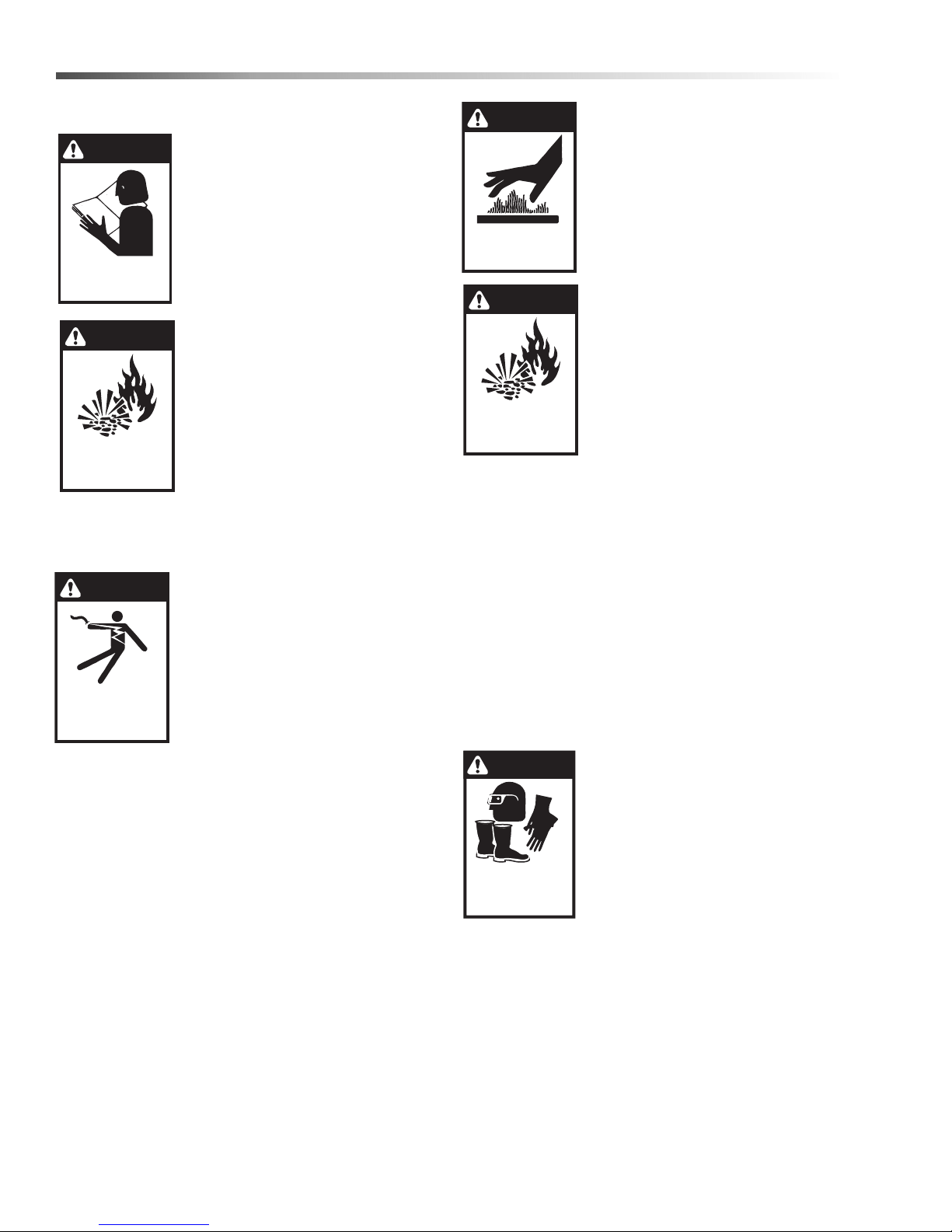
WARNING
READ OPERATOR’S
MANUAL THOROUGHLY
PRIOR TO USE.
OPERATIONS
SAFETY
MAINTENANCE
WARNING
RISK OF EXPLOSION:
AVOID FLAMMABLE
LIQUIDS.
WARNING
EXTREMELY HOT:
USE CAUTION WHEN
OPENING LID
WARNING
RISK OF EXPLOSION:
AVOID FLAMMABLE
LIQUIDS.
WARNING
USE PROTECTIVE
EYE WEAR, GLOVES
AND FOOTWEAR
WHEN OPERATING.
DANGER
KEEP WATER
SPRAY AWAY FROM
ELECTRICAL WIRING.
General Safety Information
WARNING: To reduce the risk of
injury, read operating instructions
carefully before using.
1. Read the owner’s manual thoroughly. Failure to follow instructions could cause a malfunction
of the parts washer and result in
death, serious bodily injury and/
or property damage.
WARNING: This is a heated parts
cleaner. Use only nonflammable,
noncombustible, water-based
cleaning compounds in this
machine. Do not fill or contaminate with any flammable or
combustible material such as
gasoline, alcohol, mineral spirits,
etc. Drain parts to be cleaned of
any combustible or flammable
material before placing inside cabinet. Failure to
observe this warning will create an extremely
hazardous condition.
DANGER: Keep water away from
electric wiring or fatal electric
shock may result.
2. All installations must comply with
local codes. Contact your electrician, plumber, utility company or
the selling dealer for specific
details.
Install the machine in compli-
ance with the National Electric
Code. Connect to a properly sized lockable disconnect and ground machine using the grounding stud
inside the main electrical panel.
3. Do not touch machine with wet hands or while
standing in water. Always disconnect the power
before servicing.
4. Never make adjustments on machine while it is in
operation except those prescribed in this manual.
WARNING: Use extreme caution
when opening the door of this
parts washer. Hot water/detergent
vapors will be emitted. Stand
Back! Hot cleaning solution could
cause serious injury.
5. Do not allow high concentrations
of flammable fluids, acids, or
caustics to be introduced into
this machine.
WARNING: Flammable liquids can
create fumes which can ignite
causing property damage or
severe injury.
6. Do not locate this machine in the
vicinity of any flammable vapors,
liquids or solids.
7. Before servicing the machine,
refer to all safety data sheets (SDS’s) on the
material identified in the waste stream. You must
comply with all warnings and wear all protective
clothing stated on the SDS.
8. When the machine is working, do not cover or
place in a closed space where ventilation is insufficient. Avoid installing machines in small confined
areas.
9. In cold climates, this parts washer will freeze if not
in operation and must be located in a heated enclosure.
10. Running this machine without water will damage
the heating elements and will void the warranty.
WARNING: Eye protec tion, gloves
and foot protection must be worn
while loading and unloading parts.
11. Eye protection, gloves, foot
protection and other safety
devices must be worn when
loading and unloading parts to
be cleaned.
6
CUDA 2848 Operator’s Manual 8.930 -369.0 - AG
Page 7

WARNING: Slips and falls from wet surfaces could
cause serious injury.
12. Use caution when lifting items in and out of parts
basket to prevent back injuries.
13. Always ensure that your parts washer is clean.
Pump and heating elements could be damaged by
continued build-up of sludge.
14. Check water level daily. Never allow water level to
drop below pump inlet screen or heating elements.
15. Before discarding the spent washing solution,
check with your local EPA or sewer district for
disposal regulations.
16. Do not operate the machine with the lid or door
open and do not override the safety switch.
17. After the machine stops, wait 10 seconds before
opening the lid or door.
Safety
CUDA 2848 Operator’s Manual 8.930 -369.0 - AG
7
Page 8
Operations
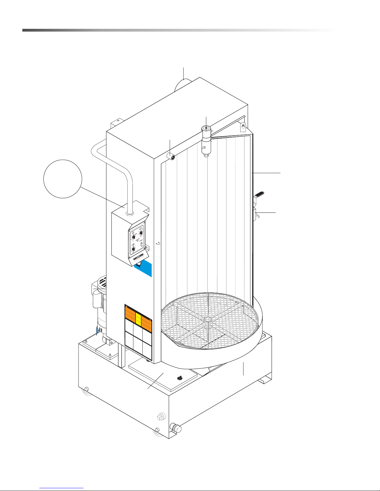
For Detail
See Control
Box Illus.
Steam Vent
Door Safety
Switch
Plunger
Revolving
Door Pivot
Assy.
Revolving
Door
Debris
Screen
Sump
Cover
Door Latch
Pump
Component Identification
Front View
LI
M
IT
ED
90-D
A
A
Y
TTENTION
LABOR W
EXTENDS T
WITH EXCLUSI
ARRANTY
USE
O
1
CUDA DETERGE
-YEA
ON
VE USE OF
R
DETERGENT
L
Y CU
LABO
NT
S
D
R
A APP
W
ARRANTY
S
M
IX
T
R
O EX
DET
O
5
VED
-GALLONS (15
E
RGEN
TEND
T
O 1-YEAR!
For CU
TS
1
L
LITER
B (
D
A
1
/
h
Ap
2
t
S
KG
tp:/
) OF
p
roved Dete
) P
/
w
ER
W
w
A
w
TE
call 8
.cuda
R
r
88-319
usa
g
ents visit
.com or
-0882
9.807-513.
0
PR
Thi
E
s
W
C
co
i
s
A
m
ARNING
UCION
a
b
Do
ust
heat
not
i
b
mate
ed
l
e
,
fi
w
/
pa
l
to
rial
l
a
A
be
t
r
or
er
t
D
s
su
placin
-bas
VE
contami
c
c
c
lea
lean
h
ed
R
as
an
n
g
TI
e
ed
gasol
c
e
r
inside
.
nat
l
x
SSEM
e
t
of
Use
anin
rem
e
i
a
n
w
n
e,
e
cabin
g
on
y
i
l
t
Es
y haza
alcoho
h
compound
E
co
l
y
te
a
N
m
e
n
nonflamm
ment
t
T
y
b
e
.
r
u
s
F
d
l
flamma
,
s
a
ous
min
u
t
i
inflama
lure
e
i
n
b
s
en
le
era
limp
conditi
in
to
mate
or
a
es
b
b
l
th
le
spirit
obs
l
b
t
i
fl
e
ador
a
is
les
C
,
amm
or
e
ri
máqui
on.
C
t
n
e
al
ma
c
on-
A
y
r
s
UI
.
co
ve
Drene
infla
,
de
no
a
c
material
et
m
UTION
b
h
D
this
na
c
le
i
b
co
n
pa
A
.
ma
ust
e
D
descuida
mate
componente
m
DO
las
.
r
rain
warni
te
b
b
i
b
l
u
s
e
le
pa
s
nes
infla
r
pa
c
/
ial
qu
t
i
o
n
r
b
A
r
m
tes
g
e
le
t
e
be
ma
T
s
obser
o
wil
xtre
s
H
se
a se
T
,
.
f
ore
gasolina
b
N
l
s
EN
Be
le
O
o
madament
creat
calient
de
a
v
r lim
llenar
ar
f
T
TION
ore
limpieza
n
es
Ce
e
t
pi
e
W
sec
,
a
op
s
ta
a
adas de
o
.
nett
lc
s
Uti
seuleme
cont
A
de
e pelig
ond
prec
o
en
hol
lice
in
TE
o
base
arm
y
ing
amina
inflam
eu
s to
aucione
,
cualqui
t
e
r
sola
r
r
o
s
PR
R
o
/tu
nt
a
lid
encias
ducir
s
gua
co
de
all
r
a
m
de
rnta
-
,
s.
co
m
EC
wai
a
pièces
,
s
s
o
W
b
e
b
de
n
no
,
w
u
r co
netto
le
minera
pued
en
b
A
algún
stib
sp
s
s
t 5
le to
sp
ARNING
.
UCION
maté
m
à
N
inn
•
el
les
y
r
e
e
es
b
l’inté
eu
a
n
ust
pa
s
y
les
ing
t
gabine
Ma
te
riau
crea
créer des
r
s
top
s
c
i
ls
rieu
b
,
hauf
à
y
c
.
le
:
x
r
hine
gasolin
ajout
b
/
se
lo
co
o
r
ase
A
t
fé
e
•
du
cka
condicio
m
.
D
.
A
sit
er
b
d’eau
m
Uti
Si
VE
cabin
Inst
usti
b
G
e
ou
uatio
u
• For
,
lise
CALIENTE
le
st b
a
R
b
U
lc
cont
alla
,
disco
le
e
Antes
-
TI
r
non
ool
t
ns risquée
s
A
.
e c
d
o
S
Ne
tio
aminer
a
,
espe
supp
u
S
n
et
co
OPER
onnecte
s
p
at
nnec
n m
inflamma
EM
c
de
m
a
.
•
ce
s
Vider
lea
b
re 5
que
obs
usti
t
us
a
E
ly
ab
s
Do n
ve
t.
appare
st 9
.
IMP
A
T
O
IN
comp
R
T
G
AN
m
lete
T
INST
a
:
n
Be
ly
ual p
inst
f
am
f
ore
r
r
ucted
R
i
o
Be
li
op
vide
a
r
f
i
ore
e
z
indiv
e
r
d
tain t
atin
.
l
y
Only
o
ours
a
g this
iduals
he pump i
ding pa
soluti
autho
elf w
ons ar
sho
i
1
th inst
r
.
r
t
Fill
s o
i
z
s off a
uld o
ed an
e a
nto tur
tank
W
t
p
nd not
o
er
a
per
with
t
ate this machi
e
nta
Ch
r
atin
l
e
b
w
e
v
le/ b
r
2
unni
c
el sh
ate
g tem
.
k dail
Pro
r and
ng and
ould
g
p
y
r
op
.
am
e
cleani
r
atur
e
b
heate
r
e
ation
s
2
o
" bel
luti
ng so
3.
.
r tim
Al
on.
O
o
l
w the
pen do
o
er
w
ba
t
f
ime
or de
s
or/
k
et
f
thr
or
sired per
l
/t
id an
ough
u
unit
r
ntab
ba
d pl
to prehea
s
the bo
k
l
e
et/
ace
heigh
.
B
t
u
e ce
4
r
a
ttom
ntab
.
r
Clos
t or
ti
c
r
tain
les to be
or
l
w
e
e door
.
eig
set
Do n
b
no pa
e
ht li
y
t
o
on
cleani
o
/lid
w
mit
t
d the si
ash, tu
e
and lat
xceed
f
has
or
ng ti
this sp
5.
r
e
m
n
xpire
ch se
Bef
“
e
w
.
Pump will
ash
ore
r
d
cure
off
.
open
cycl
and
l
ning
e
ing
”
w
st
tim
ait
.
the d
a
and
Thi
r
5 second
t and
s will
e
oor/li
xcess
al
d, t
l
s
o
w
w ste
f
or m
u
ater t
r
n
am t
ach
M
o
d
AI
r
o esca
ain
N
f
r
T
om
T
EN
h
e
f
o
H
AN
l
l
i
o
g
w
he
i
C
n
n
r
a
g
u
E
n
s
s
c
a
c
INST
e
he
g
.
I
e
M
d
m
u
P
l
a
O
e
y
f
ore
R
i
r
s
RUCTION
T
e
b
AN
q
a
d
u
ser
s
r
ire
aini
T
e
:
d
vice t
Be sure
m
o
ng su
o
n
D
r
e
AI
his m
f
r
m
L
e
Y:
electr
p
•
.
achi
On
Chec
ly quali
n
ical supply i
e.
off the
k
w
fied personnel
ater
hea
w
•
l
e
ater
ter
v
el in
el
Re
daily will
eme
•
m
the s
ove an
nt
Vi
.
ump
sually ch
pr
d clea
and
e
v
ent damag
clean i
nal p
e
n de
c
WEE
k
f
ositio
b
or
f nee
r
is sc
K
plugged n
•
L
n.
Y
ded
reen.
:
Gr
.
M
ease/
Reins
ON
ozzl
TH
oil d
tall i
•
L
Y
oor hing
P
:
e
r
•
f
o
r
m
D
e
r
v
s
ain
i
.
s
u
g
a
wash so
r
l c
it fro
h
ta
e
c
m b
k
k
en to
lut
o
ott
men
f
ion fr
t
u
o
•
r
a
m
n
t du
v
t
oi
a
of the
om su
When
b
d
r
ing
bend
w
su
mp
sump
the cle
ater
i
m
n
g
p
ge
, add
.
or
Car
has b
ani
nt
N
da
O
f
ng proces
or
TE:
the r
ma
be
een cle
y
our
Dissol
f
ecom
ore
m
amo
addi
achi
aned a
men
ve cle
unt to
ng the
n
ded qu
e
.
aning
t
he tank
ma
p
n
o
u
wd
f
.
acture
er in
r
’
s re
N
t co
connec
er
b
rir la
c
l
s
la barr
es
T
d to
les
b
de
ve
eg
0 de
le
ot
pièces
mpl
r
s
s
et
il
undo
ce
a
mat
tapa
use
a
•
non
v
gr
s
y wit
p
tio
an
a
ériaux
a
r
e
La
be
cont
dete
r
ve
op
t
,
s
n
es
otato
de
,
r
m
para
use
h N
e
tis
l
o
enant
C.
r
les
nga
elé
EA
áq
l
w gr
sement
y s
ria
EC co
•
place
uina
wire
ctri
.
i
s
UCTION
mach
d pro
e
r
t
t
he specified
a
y
w
y
.
With m
er
r
w
ash
ine to
pe the
y
our pa
av
q
u
e
dai
e
n the
l
e
d
, re
e shou
gi
s
nd re
antity o
to
comm
z
A
ad
U
La
ed
e
v
co
•
s
ant d’ouvrir le
debe
s a
e flo
r
ins
d
peut
CH
atte
e
de
Para la
cce
.
tala
or
se
es
ndez 5 se
permet
A
pt
or
do
ció
gur
S
tar c
a
U
gra
s c
te
b
par
n d
le
DE
ida
ur/plaque tournante
in
No
on
tre au bras
one
couve
de
f
e
ebe
or
a a
r
d
,
condes pour
u
e
.
utili
ct
l
xi
ctad
e
l me
i
on
cu
vel
one
INST
r
ce
t,
p
mplir con el
.
a a
nos
e
s de
por
r
•
ly
v
de tourner
aporisa
un
a
90 gr
IMP
R
deb
s
L
ali
k
’a
en
UCCIONESDE OP
e
O
t, be
ppa
n
menta
pleta
R
e
ajo
c
d
ado
ve
.
the
T
huf
’
ANTE
arrêt
•
reil doi
código
cer
r
men
perso
.
.
del
r
s centí
w
o
e
-
ción
L
ash
u
er
te con el m
’ins
:
•
i
éste equi
An
niv
nal
ll
lution
a
t être
,
tes de o
NE
us
tal
b
P
auto
el d
grad
carg
le d
o
acce
.
latio
ur le
e c
C.
r
el
p
co
iza
a
e t
a
fils
esté a
o
os
sobr
pis
a
n
ss do
pa
.
Antes
d
n d
u
b
ra
aille
nnec
o
a
.
r
le
a
y de
po
l
estén a tem
e la
o
r
d
Ne
cco
paga
oit se
a
o
e
.
e
ER
r
u
-
de ab
a
l
s
e
iod of
o
t
té
b
vant acc
pas
.
p
o
p
idam
quip
r
da y s
e
rnam
d
1.
p
à un
A
r
eme
ació
r
co
Llene
r
opr
util
o
CI
ir
ente
t clean
,
la
esa/ca
p
in fun
n
f
n que
am
se
e
ON INST
nt d
f
ié
ni
r
puer
ise
el dep
o
capacit
at
ept
iliar
v
rm
e
ctio
u
el del
ing
c
.
r
r un
nasta, asegúre
e
ion
se inc
a de
ta/c
er
ce
ícese c
e
l’al
clea
r
ósito
nneur
a
s
au
agua debe e
au
ado d
ubie
o
r
2
funcio
ca
, y
s pr
.
.
ime
Prog
l
u
mo
V
n
y
o
q
co
r
cod
e
libr
e
ot
ta o l
onto
m
u
ebe op
r
.
ifiqu
e
n
Sol
ntat
des of t
r
-
nam
r
u
a
ins
ope
a
las s
e o
de
e NE
m
gua y l
as piez
e el
o
se de
e
ion
r
i
ent
a
a
90
u un
star
oluc
precal
e
ción
r
h
ar
l
ni
C.
o
T
e
de
,
IMPO
a so
utili
R
.
v
em
3
que l
ione
as de
2" po
el di
ash ca
.
desea
gra
UCTIONS D’OP
Abr
ie
grés
po
l
nte la
v
uci
s de lim
R
a bom
a
ser des
ous
r
a la
r deb
izad
r
T
de
iam
ón pa
nam
binet
A
d
Cel
o
N
mac
pu
comp
soluci
infé
.
or d
ent
D
T
ajo
to the de
achine
ba
esa/can
:
pieza
.
bre
e
ra
eje p
siu
A
hine
e
r
el cal
au
de la
ta/ta
vant d’ut
.
lèt
rie
l
p
im
un unti
ón pa
to
a
s
e
los li
asar
se
pi
d
u
m
.
r
pa y co
s pu
ou du char
entado
is
e
asta,
e
r
sir
ent
v
é et
.
el
z
r
r
mites
un
a lim
a
a
l ti
l
e
a
i
f
.
e
li
it ê
d
El
ondo
a
v
s
ser
r
me
aseg
v
f
ad
’
ta de a
tiem
o
assu
loqu
4
r pa
ec le
tre utilisé
pieza
r
esp
.
o
m
ÉR
cet
Cierre la pu
.
ni el
p
é
ú
gem
po pa
r
cycle t
e la
r
a
a el p
.
r
t
er
ecificado
m
ese de
e
s
.
c
A
A
-
a
e
et que les s
mach
s pieza
que la
vant l’
ent d
stop
per
f
n
n
o
TION
r
e seu
uel d
p
eríod
a que
ncti
imer
ímet
osición
l
qu
es piè
a
in
spin
onnem
o
e
s de p
v
pom
’inst
s a
e
leme
1
u
o de
r
ad
e nin
la un
ro d
ta/tapa
,
.
v
cabine
e
f
Rem
du
o
a
l
r
r
de
a
pe es
oluti
ces su
”
m
ture
uctio
e la t
nt pa
r
v
r
eso y a
guna p
al tie
en
t
ante
il
idad
ar en la to
5
s
i
plir
.
a
Le n
.
la
y aseg
Ant
t
ons d
t
de la
.
r
n
v
o
t en p
isez
r du
m
le r
el t
a
r la
r
f
nam
r
o
i
po dese
es de
ieza s
,
v
ltu
po
ajuste
u
eau d
-
e
ta
po
ciclo
ie
ése
r
per
r
ni
osition
ure el can
r
l
a pa
mpo
esa
tes
a
b
r
2
.
-
r
C
v
le to
.
r
sonnel
te/du co
o
ab
a
de
v
Pr
dej
d’a
’eau
oir
ette
el
.
g
ad
r
sele
No
r
a el
e son
o
ir
u
arr
d’ea
e de
l
g
temp
o
a
ccè
la pu
r
r
nante/
.
la p
v
doit se
el
amm
La
e
gabi
ccionad
ado
ê
dad
xc
u
s
t et n
t à te
exceso
u et d’u
gi
vercl
.
é
o
eda
bomb
Vér
e
y espe
r
r
rizad
o
p
er le
nete de
a
iode
r
le p
.
o
ta/cub
Con
tro
r
e
mp
.
ur
e
r
a
S
g
e
n
u
t
s
m
e
.
a
i
n
t
e
-
s OFF be
shou
ld
l
y
.
T
op
ping
e to t
he
s
.
Remo
e
v
e
xact
o
r
ig
i
r
i
v
e
c
h
a
m
i
n
o
.
v
e san
n
d/
g
ld be
h
ea
.
te
r
el
e
filled
with
f det
e
r
w
-
a
r
m
w
ate
ended
r
e
ifi
Esto
3
o
f
er qu
que l’
de a
mi
ani
a ar
or
o
.
.
u
n
de
é
Ou
nct
v
la m
e so
de
r
re 5 s
er à
atur
i
nu
e
e
r
f
pe
r
v
ionne
onctio
ancar
r
,
otidi
gua
t
ta, apa
r
“c
appareil p
e
lutio
ir l
sur
5 cm
áquin
r
e de
r
m
iclo de
egun
ie de
I
a p
dren
enn
itirá qu
N
le pa
á y fu
n de
nnement
aucu
S
o
(2
a
gue el tem
eme
chauf
dos p
r
e de l
t
T
e
nett
nier
po) so
/
réch
nciona
e el
R
c
ne pièc
du p
nt.
ou
a
U
E
/pla
o
f
as pie
a
r
sou
v
auf
v
y
l
4.
a qu
ge de
e
ainer
C
p
apor
a
us les
r
rá
que to
l
g
F
p
a
t et
fe la so
hait
C
e dépa
e
b
o
e
n
e la m
.
a
z
r
r
salga
d
izado
/plaq
mez l
I
s
a
l’app
placez l
é
e
ON
a
s
La m
e
d
u
.
m
s
.
o
Pré
r
e
lutio
ssant l
a
n
áqu
ue to
v
r del
a po
e
del g
arei
n
a
e
E
n
achin
cycl
t
n
r
e
v
o
es a
n de n
u
t
ina
S
n
e
oir
l po
IM
n
r
p
u
i
.
m
te/cou
e
e pai
u
abine
r
As
u
du t
D
nant
”
jusqu’
PO
e prête po
ed
i
r
au tem
s
e
ur
ticle
o
n
s
E
AP
e
ett
t
ur
R
5
p
o
ner
emp
e
r
te y
.
r
v
T
e
o
ez-
A
o
s
q
.
M
e
à ce
A
AN
q
y
à être
m
u
GAD
r
v
ag
u
debe
ou d
t et
e
ps de l
v
an
s
e
ANT
e
T
ous
d
s
e
r
que temps
ur l
E
i
t d’ou
e
cycle d
i
.
r
o
v
O ant
ans le
:
u
p
rep
erro
d
e
A
l
qu’i
n
r
a
e
DIA
e
a
s
l
vé
m
l
E
a
s
l’appa
egú
v
e
ar
l
uil
e
v
l n’y
a
es de
r
a
e
q
i
ag
n
N
RIAM
v
r la
n
ar e
f
lez de
u
t
on
a
l
t
rese
a
a
i
e
e
I
p
g
• Com
s’échapp
v
s
n
M
a
reil s’ar
est
, to
d au-del
o
e dé
po
age
sta m
i
.
élec
m
vacia
c
EN
U
de que
I
o
r
u
i
t
E
e
n
f
n
p
e
r
açon
s
à l’a
n
u
t
ne
i
tionné
T
/le c
i
i
è
N
t
ré
áquin
nu
o
r
E
s
c
rête
z le m
p
er
o
el cá
e
Man
.
à
:
m
T
a
La p
rrêt
r
s
o
m
ueb
c
sécu
el sistem
á
.
du
O
u
de
i
ó
s
soit é
á
a.
v
et
tener
n,
s
r
cab
erc
f
elem
e el
om
te
i
r
n
f
e
to
r
e
r
a
uteur
ita
r
c
e
• Retir
l
st
.
u
tten
e
u
Sólo
pe
cu
in
ni
c
r
el n
,
i
á
e
ento
mett
n
r
o
et
e
nt
e
a el
e
v
ul
f
dre
.
n
o
el del
r.
e
“
et
te
é
nctio
per
w
i
.
v
C
• Com
.
éc
del
re la
ash
el a
à l’
pend
o
el
e y lim
t
sonal c
a
DIRECTIVES D’EN
agua
r
e
nne
calent
ico es
decuad
Le tab
p
xcès d
mi
ant
e
r
r
n
mett
a
pie
p
ute
en el
cor
5 seconde
r
Une
té
ado
ali
uebe
leau
’eau
o del
r
los r
rect
r
ficado
i
a
e du
r
uti
la p
.
cá
à la
fr
visual
ame
su
de s
esiduos de
équent.
agua
S
lisation plu
r
osición
EMAN
i
t
v
er
v
s qu
a
apeu
’éc
n
nt
t
di
IMP
m
e
e
o
•
a
.
e
Reti
e
en
vitar
A
uler de
r
st
r de
iame
o
L
O
te q
r
a
M
Lu
la
f
igin
R
s im
ondé sur
v
á
re y
E
T
an
M
b
d
N
u
nt
ANT
c
r
al
E
r
e las
v
T
añar el
t de vi
ique
po
par
e
iba
o
NS
exacta.
E
limp
.
s
:
TRETIE
r
.
er c
tante
U
:
• Realice una
las
S’as
une u
boqui
A
ie si
der
L
Q
et ap
M
bisa
peut
U
sure
E
le r
es ne
O
llas
N
tilisa
TID
parei
g
T
ése
de l
-
•
r q
r
E
e
a
están
:
xiger
N
cesa
IENN
tion
s de
•
ue le
r
a tor
l.
Vé
v
oi
Dre
m
la pu
r
r
r
u
v
instal
.
ifier
EM
i
Seul
nam
o
e
o
systèm
n e
e
.
r
y
Reins
n
r
ifica
en
E
quoti
voi
e l
cá
ntr
e
esa.
N
adas
le pe
n
r
a solu
r
r
T
ta
d’en
ción vi
e
etien
.
ter
Le r
:
e él
.
.
tale
•
dien
daña
los se
dom
r
ec
s
plus
en
ción
em
onnel
Démon
sua
nem
tr
r el
limpieza
mag
•
ique
plissa
de lim
d
l d
•
im
ent le
elem
quali
e la
Vé
er l’é
e
ento
ter
Una
ge q
s
r
.
t
ca
ifier v
pie
ni
et netto
ento
fié do
à l
s
st
lém
.
v
v
dena de pr
uotid
za de
a
r
’arr
Debe
eau d’
ez q
ué
g
del ca
e
isue
reg
it r
n
e
dans la
êt
t cha
s
ien
y
ue el
máq
l cá
.
é
ue la
HEBDOM
er
Dém
llem
tener
eau da
-
N
le fil
d’eau p
lenta
r
O
uf
uina.
te
cá
ent si
opu
cantid
positi
T
f
onter
r
cuid
a
•
A
, re
tre à
l
r
nt
o
dor
ns le
ter es
:
lsión
.
a
D
tire
e
A
des
G
l
ado de
durante el
on in
et nett
i
r
s
ad re
t
D
dé
me
an
r
u
ME
del
aisser/hu
AIR
ré
tá li
e
b
q
b
l
t d’év
s
v
r
itiale e
u
NS
uses
-
a
i
com
s
e
EME
mpio
fon
no d
o
.
e
e
y
•
UELL
l
d
n
e
do de
iter
sont bouchée
e
r
pro
e
l
N
y re
, le cas
iler le
ndad
x
a
o
t
Procéder
a
e
T
b
c
c
rg
:
lar
a
EME
ceso d
t
e
n
llen
e
a
s
.
t
o
n
i
de la
d
t
de
pent
e
échéa
a
o de
N
•
d
e
detergen
T
e
à un co
n
re
:
ures
ta
a
agua,
Assé
c
s/ob
g
b
o
n
u
le
m
t
.
/cha
a
Réin
to
e
-
cher
sa
c
n
ntrôl
a
te pa
u
d
b
l
r
r
a
i
nièr
e
nant
le/
stalle
d
la s
n
e visu
êtr
a
t
g
e
r
p
es de
a la
r
e
e
a
a
o
olutio
.
r
vier
n
r
p
ou de l
t
e
el de
r
e
ises p
l
s
la
•
se t
f
d
a
n de
b
e
po
la cha
ri
L
a
’end
rou
c
our
o
r
a
g
l
t
r
a
n
re
e
s
v
v
t
.
éviter
q
e
o
g
ant a
age du ré
q
u
.
îne d’
a
mm
u
e
r
N
a
-
l
n
O
e
ager
u
t
de pli
i
TE:
r
t
e
f
é
é
o
n
s
d’ajouter dans
nd
d
tr
e
Bie
se
au co
e
aînement
r
.
v
er/
d
r
Des p
o
v
é
n
i
oi
r
cour
t
disso
e
a
urs
r
r
, et en
g
é
e
r
t
ber
é
é
du proce
n
c
udre
t
n
a
l’élé
e
r
u
l
eco
e
t
le ré
ti
t
v
o
o
la po
er
y
n
m
m
é
s
se
tout
s
ent cha
m
e
doiv
sus de
t
r
a
udre
v
r
n
e
oi
d
m
e
r
é
.
n
p
dans
e
u
t
net
li
f
p
f
d
ant
o
’
e
t
u
o
l’ea
a
r
y
u
v
a
,
o
g
aj
t
u chaude
e
r
e
o
.
u
a
t
p
e
p
r
a
l
a
r
e
i
a
l
.
v
a
nt
8.922-402.0
8
CUDA 2848 Operator’s Manual 8.930 -369.0 - AG
Page 9
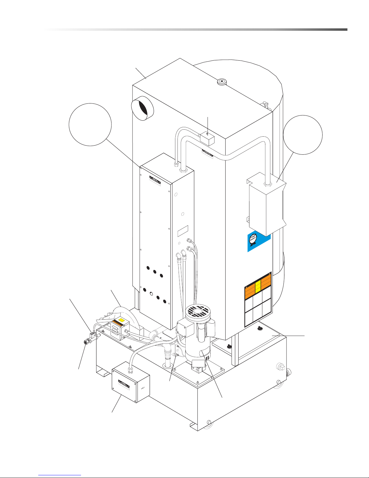
Component Identification
KEEP
DRY
ATTENTION
USE ON
L
Y CU
D
A AP
P
R
O
VED
DETERGENTS
T
O EXTEND
LABO
R
W
ARRANTY
T
O 1-YEAR!
MIX DETERGENTS 1 LB (1/2 KG) PER
5-GALLONS (15 LITERS) OF
W
A
TE
R
For CUD
A App
r
o
ved Dete
r
g
ents visit
http://www
.cudausa.com
or
call 888-319-0882
9.807
-51
3.
0
90-D
A
Y
LABOR WARRAN
TY
EXTEN
DS
TO 1
-YEAR
WITH
EXCLUS
IVE USE OF
CU
DA
D
ETERGENT
S
LI
MIT
E
D
T
hi
s
is
a
heated
p
a
r
ts
c
l
e
an
e
r
.
Us
e
o
n
l
y
n
o
n
fl
am
m
a
b
l
e
,
non
-
c
o
m
b
ust
i
b
l
e
,
wate
r
-based
c
l
e
a
n
in
g
co
m
pound
s
in
this
m
a
c
h
i
n
e.
Do
n
ot
fil
l
o
r
c
o
nta
m
in
a
t
e
w
ith
a
n
y
fl
a
mm
a
b
le
o
r
co
m
b
ust
i
b
le
mat
e
r
ia
l
s
u
c
h
a
s
gas
o
l
i
n
e
,
a
lc
oho
l
,
min
e
ra
l
s
p
iri
t
s
,
e
t
c
.
D
r
ai
n
p
a
r
ts
to
b
e
c
l
e
aned
o
f
a
ny
c
o
m
b
ust
i
b
le
o
r
fl
a
mm
a
b
le
m
ateria
l
b
ef
or
e
pl
a
c
i
n
g
i
nsi
d
e
c
a
b
i
n
e
t
.
F
ailure
to
o
b
s
e
r
v
e
this
warnin
g
w
ill
create
a
n
ex
t
rem
e
l
y haza
r
d
o
u
s
c
ond
i
t
i
on
.
Este
e
s
u
n
limpiador
d
e
p
a
r
tes
q
u
e
s
e
c
ali
ent
a
.
Utilice
s
o
l
a
-
me
nt
e
en
e
st
a
má
q
u
in
a
c
o
mponent
e
s
d
e
l
i
m
p
ie
z
a
bas
e
a
g
u
a
,
n
o
i
nfla
m
a
b
le
s
y
n
o
co
m
bu
sti
b
le
s
.
No
l
l
e
n
ar
o
co
n
ta
m
ina
r
c
o
n
a
l
gún
mat
e
r
ia
l
i
nfl
a
ma
b
le
co
mo
,
gas
o
l
in
a
,
a
lc
oh
o
l
,
e
s
e
nc
ia
s
min
e
ra
l
e
s
,
e
t
c
.
D
ren
e
l
as
p
a
r
t
e
s
a
s
e
r
l
i
mp
ia
das
de
cual
q
u
i
e
r
c
o
m
b
usti
b
le o
mat
e
r
ia
l
i
nfl
a
m
a
b
le
ant
e
s
d
e
in
t
r
odu
c
i
r
e
n
e
l
gabi
n
et
e
.
Si
des
c
u
i
d
a
o
b
s
e
r
v
ar
e
s
t
as
pr
e
c
a
u
c
i
on
es,
pued
e
n
c
r
e
a
r
s
e
co
n
di
ci
o-
nes
e
x
t
rema
da
me
n
t
e
pe
li
g
r
osa
s
.
Ce
n
e
t
t
o
y
eur
d
e
pièces
e
s
t
c
hau
f
f
é
.
Utiliser
d
a
n
s
ce
t
appa
rei
l
s
e
u
le
me
n
t
d
es
nettoy
e
u
r
s
à
bas
e
d
’
e
au
,
n
o
n
c
om
b
usti
b
le
s
e
t
non
i
nfl
a
mm
a
b
le
s
.
Ne
pa
s
y
a
j
out
e
r
o
u
contamin
er
a
v
ec
d
e
s
matériaux
c
o
mbus
t
i
b
le
s
t
el
s
:
g
a
sol
in
e
,
a
lc
o
o
l
,
e
t
c
.
Vi
d
e
r
le
s
piè
c
e
s
c
o
nte
n
ant
d
e
s
matériau
x
co
m
b
usti
b
le
s
o
u
i
nfl
a
mma
b
le
s
a
v
a
n
t
d
e
le
s
pl
a
c
e
r
à
l’intérieur
d
u
c
a
b
ine
t
.
Ne
p
a
s
o
b
s
e
r
v
e
r
c
es
a
ve
r
t
i
s
se
me
nt
s
p
e
u
t
cr
é
e
r
d
e
s
s
i
tuati
o
n
s
r
i
squ
é
e
s.
HO
T
W
A
TE
R
Be
f
or
e
ope
ni
ng li
d
, wait
5
se
conds
to a
llo
w
sp
r
a
y
arm/
turnta
b
l
e t
o st
op
s
p
in
ning
.
A
G
U
A
CALIENTE
Antes
de
a
brir
la
tap
a
,
espe
re
5
seg
undos para
que
l
a
b
ar
ra
r
otat
o
r
i
a
se
dete
nga.
E
A
U
CH
A
UD
E
A
v
ant d’ouvrir
le couv
e
r
t,
attendez 5 secondes pour
permettre a
u bras
v
aporis
a
-
t
e
u
r
/pl
a
q
u
e t
ou
rna
n
te
d’a
rr
ête
r
d
e
t
o
urne
r
.
W
ARNIN
G
P
RE
C
AU
C
ION
/
A
D
V
E
R
TISS
E
ME
N
T
CA
UTIO
N
C
U
I
D
AD
O
/
A
TTENTION
OPER
A
TING
INST
R
UCTIO
NS INST
R
UCCIONESDE O
PER
A
CION
INST
R
UCTIO
NS D’O
P
É
R
A
TIO
N
IMPO
R
T
AN
T
:
Be
f
ore op
e
r
ating this machin
e
,
completely
f
amil
ia
r
ize
y
ourself with i
nst
r
u
ctio
n
man
u
al
p
r
o
vided
.
On
l
y
au
t
h
o
r
i
z
e
d an
d p
r
op
e
r
ly
inst
r
u
cte
d
in
d
ivi
d
u
als
s
ho
u
ld
o
pe
r
at
e t
his machin
e
.
Be
f
o
r
e
l
o
a
d
in
g p
a
r
t
s
o
n
to
tu
r
n
t
a
b
le/ ba
s
k
et, be ce
r
-
t
a
in
t
he
p
u
m
p
i
s o
ff
a
n
d
n
ot
r
u
n
n
i
n
g
a
n
d t
h
e
w
a
sh
s
o
l
u
t
ion
s
a
r
e
a
t o
p
e
r
ating temp
e
r
a
tur
e
.
1
.
Fill
t
a
nk
w
it
h
w
ater and cleaning solution
.
W
a
te
r
l
e
v
e
l s
h
o
u
l
d
be
2
"
b
e
l
o
w the access door
s
.
Chec
k
da
ily
.
2
.
Pro
g
r
am
he
a
te
r
t
imer
for desired pe
r
i
o
d
o
f
o
pe
r
a
tio
n
.
All
o
w ti
me
f
o
r
un
it
t
o
p
r
e
h
e
a
t
c
le
a
nin
g
solution.
3
.
O
p
e
n
d
oo
r
/
l
id
a
nd
p
la
c
e
a
r
ticles to be clean onto
b
as
k
et/tu
r
n
t
a
bl
e.
Be
c
e
r
t
a
in
n
o
p
a
r
t
s
p
r
ot
r
u
d
e
t
hrou
g
h t
h
e b
o
tto
m
or
b
e
y
o
n
d
th
e
s
ide
s
of
t
he
b
as
k
et/tu
r
n
t
a
bl
e
.
Do not
e
xceed the specifi
ed
h
ei
g
h
t o
r
w
e
igh
t
l
i
mi
t
f
or this spr
a
y
w
a
s
h
c
a
b
i
n
et.
4
.
Close door
/lid and l
atch securely
.
With machine
set to
w
a
sh, tu
r
n
“
w
a
sh
c
yc
le”
timer to the desi
red
c
lea
n
ing
t
i
m
e
.
Pump wil
l st
a
r
t
an
d
r
u
n un
til
t
i
m
e
h
as
e
x
pi
r
e
d
.
5
.
Be
f
ore opening the door/lid, tur
n
w
ash cycle timer
o
ff
a
n
d
w
ait 5 seconds
f
or machine to stop spin
-
n
ing.
T
h
is
w
il
l
a
l
l
o
w steam
to
escape the cabinet
a
n
d
e
xc
es
s
w
a
te
r
t
o
d
r
a
in
f
ro
m
y
our pa
r
t
s
.
IMPO
R
TANTE:
Antes
de op
a
r
a
r
el
e
qu
i
p
o
,
f
amil
iarícese com
-
p
let
a
me
n
t
e
co
n
el
ma
n
u
al
d
e o
p
e
r
a
ció
n
qu
e
se
i
nc
l
u
y
e
.
So
lo
p
e
r
so
n
al
a
uto
r
iza
d
o
y
d
e
b
i
d
a
m
en
t
e
c
a
p
a
c
i
t
ad
o
deb
e o
p
a
r
a
r
é
ste
e
qu
i
p
o
.
Antes de ab
r
ir
la
p
ue
r
t
a
/c
u
bie
r
ta
o las pi
ezas de
c
a
r
ga
s
ob
r
e
l
a
t
o
r
n
a
m
es
a
/ca
n
a
s
t
a
, a
s
e
g
úr
e
s
e
d
e qu
e l
a
bom
ba
esté apagada y si
n funciona
r
, y que las soluciones de li
mpieza
estén a temp
e
r
a
tu
r
a
de
f
un
c
io
n
a
m
ien
t
o
.
1
.
Lle
ne el depósito con agua y la sol
ución pa
r
a
li
m
p
iez
a
.
El
n
i
v
e
l d
e
l a
g
u
a
d
e
b
e
e
st
a
r
2"
p
o
r
d
e
b
a
j
o
d
e
la
s
pu
e
r
ta de ac
-
c
e
s
o
.
V
e
r
ifi
qu
e
el
n
i
v
el di
a
r
iament
e
.
2
.
Pr
o
g
r
a
me
e
l
T
empor
i
z
ad
o
r
de
l
ca
l
e
nt
a
d
o
r
p
a
r
a
el
p
e
r
í
o
d
o
d
e
o
pe
r
ación desead
o
.
D
e
j
e
pas
a
r
u
n
ti
e
mpo
p
a
r
a
que
la
u
ni
d
a
d
p
r
e
ca
li
e
n
t
e
l
a
so
luci
ó
n
pa
r
a
l
i
mp
iez
a
.
3
.
Ab
r
a
la
p
u
e
r
ta/tapa y coloque las pi
eza
s a
l
a
v
ar en l
a to
r
-
n
a
m
esa
/ca
n
a
s
ta
, a
s
e
g
ú
r
e
s
e
d
e qu
e n
i
n
gu
n
a p
i
ez
a
s
o
-
b
r
e
pa
s
e el
f
o
n
d
o
n
i
e
l p
e
r
íme
t
r
o
de
la
to
r
namesa
.
No
e
xceda
los limites esp
ecificados de peso y altu
r
a pa
r
a
el
g
ab
i
n
et
e
de
l
a
v
ad
o
.
4.
Ci
e
r
r
e
l
a
p
u
e
r
ta/tapa y asegure el candado
.
C
o
n
l
a
m
á
q
ui
n
a
e
n po
s
i
c
i
ó
n
d
e
l
a
v
a
r
, ajuste el temp
o
r
iz
ad
o
r
de
“
c
ic
l
o
de
la
v
ad
o
”
a
l
t
ie
m
p
o
de
s
ea
d
o
.
L
a
b
om
b
a
a
r
r
ancará y funcionará
d
u
r
ante el ti
empo selecci
onad
o
.
5
.
Antes de ab
r
ir
la
p
u
e
r
t
a
/c
u
bier
t
a
,
a
p
a
g
u
e el
te
m
p
or
i
z
ad
o
r
de
l
c
iclo de
l
a
v
a
d
o
y
es
p
e
r
e
5
se
g
u
n
d
o
s p
a
r
a
qu
e
la
m
áq
u
in
a
d
eje
d
e
g
i
r
a
r
.
Esto pe
r
mitir
á que el
v
a
p
o
r
s
a
lga
del
ga
b
ine
t
e
y
e
l
e
xceso de agua drene de las
piez
a
s
.
IMPO
R
T
AN
T
:
A
v
ant d’utili
ser cette machin
e
,
f
a
m
i
li
a
r
ise
z
-
v
ous complèteme
nt
a
v
e
c l
e
ma
n
u
el
d
’
ins
t
r
u
cti
o
n
fo
u
r
n
i
.
Cette
machine
d
e
v
r
a
it
ê
t
r
e
u
tili
s
ée
s
eu
lem
en
t
pa
r
d
u
p
e
r
so
n
n
e
l
auto
r
i
sé
e
t
fo
r
mé
.
A
v
a
nt
l’
o
u
v
e
r
t
ur
e
d
e l
a
po
r
te/du co
u
v
ercle
ou du chargement des pièces sur
la ta
b
l
e
to
u
r
n
a
n
t
e
/le
p
an
i
e
r
,
s’assurer que l
a pompe est en position arrêt et ne fo
n
c
t
i
on
n
e
pas et que les solutions de
l
a
v
a
g
e
s
on
t
à
t
e
mp
é
r
ature de
f
o
n
c
t
io
nn
e
me
n
t
.
1
.
Rempli
r le rése
r
v
o
i
r
d
’e
au
e
t
d
’un
e
so
lu
ti
o
n de
ne
tt
o
y
a
g
e
.
L
e ni
v
e
a
u
d
’ea
u
doit s
e
t
r
o
u
v
er à 5 cm (2 po) sous les
p
o
r
tes d’accè
s
.
Vé
r
i
fi
e
r
q
u
o
t
i
di
e
n
n
em
en
t.
2
.
Pr
o
gr
ammer le mi
n
u
te
r
i
e
d
e
ch
a
uff
a
g
e
d
e l
’a
pp
a
r
ei
l
p
ou
r
l
a
p
é
r
io
de
d
e
f
o
n
c
tio
nn
e
men
t
s
ou
h
ait
é
e
.
Pr
é
v
oir du temps
p
o
u
r
q
u
e
l’a
p
p
a
r
eil
p
r
éc
h
a
u
f
f
e
la
s
ol
u
tio
n
de
n
et
t
o
y
a
g
e
.
3
.
Ou
v
r
i
r
la
p
o
r
te/cou
v
e
r
t et placez les
a
r
ticles à êtr
e
la
v
é
s
u
r
l
e
pa
n
ie
r
/
p
laq
u
e t
o
u
r
n
a
n
t
e.
Assurez
-
v
o
u
s
q
u’i
l
n
’y
e
st
a
u
cu
n
e pièc
e
d
ép
a
s
s
a
n
t l
e
pa
i
n
e
r
o
u d
a
n
s
le
f
o
n
d au
-
d
el
à
d
u pa
ine
r
/
pl
a
q
u
e
to
u
r
n
an
t
e
.
4.
F
e
r
mez l
a
po
r
te/cou
v
e
r
t
et
v
e
r
rouill
e
z
d
e
f
açon sécu
r
it
ai
r
e
.
L
a
m
a
c
h
i
n
e
p
r
ê
t
e
p
o
u
r
l
e
l
a
v
a
g
e,
to
u
r
nez le mi
n
u
teur
“
w
a
s
h
c
y
c
l
e
”
au temps de la
l
a
v
age désiré
.
L
a
p
o
m
pe
f
o
nc
t
ion
n
e
r
a
jusqu’à ce que temps sélecti
onné soit écoulé
.
5
.
A
v
ant d’ou
v
r
ir la po
r
te/l
e
co
u
v
e
rc
l
e
, mettre la mi
n
ut
e
r
ie du
cycle de
l
a
v
age à
l’arrêt et attendre p
endant 5 second
es que
l’appareil s’arrête
de to
u
r
ne
r
.
Cela p
e
r
mett
r
a à la
v
apeur de
s’échapper
du cabinet et
à l’
e
xcès d’eau de s’écouler d
e
v
os
pièce
s
.
W
ARNIN
G
P
R
E
C
A
U
CIO
N
/
A
D
V
E
R
T
ISS
E
M
E
N
T
•
Ma
chine
m
ust
be
connected t
o a
p
r
op
e
r
l
y si
z
ed
lo
c
ka
b
le
di
sc
on
nect.
•
Ins
t
alla
t
ion
m
ust co
mp
l
y w
ith NE
C c
o
d
e
.
•
For
supp
l
y
con
necti
o
n
,
us
e wi
res a
cc
epta
bl
e
f
or
at le
as
t 9
0 deg
rees
C.
•
Do
n
o
t
use
be
l
o
w g
rade
floor or
grade
l
e
ve
l
.
T
h
e
f
o
l
l
o
w
i
n
g
s
ch
e
d
u
l
e
i
s
b
a
s
e
d
on
a
v
e
r
a
g
e
u
s
e
.
H
i
g
he
r
u
s
age
ma
y r
eq
u
i
r
e
m
o
r
e
f
r
e
q
u
e
n
t
m
a
in
t
e
-
n
a
n
c
e
.
I
MP
O
R
T
ANT
:
Be sure elec
t
r
i
c
a
l
s
up
p
ly
is
O
FF
be
-
f
ore dr
aining su
m
p
.
Onl
y
qu
a
lifi
e
d p
e
r
s
on
n
el
s
h
o
u
ld
s
e
r
vice this mach
in
e
.
D
A
IL
Y:
•
Chec
k
w
a
te
r
l
ev
el in the sump dail
y
.
T
o
p
p
i
n
g
off the
w
a
te
r
d
ail
y
wi
l
l pr
e
v
e
nt
d
a
m
a
g
e t
o
th
e
h
e
a
te
r
e
le
m
e
n
t.
•
Remo
v
e
an
d
cl
e
a
n
d
e
b
r
is screen.
•
Visually che
c
k
f
o
r
plu
g
g
e
d
no
z
zl
e
s
.
Re
m
o
v
e
a
n
d
c
le
an
if
n
ee
d
ed
.
R
e
i
n
sta
ll in
t
he
e
xa
ct
o
r
ig
i
-
n
al
p
o
s
i
t
ion
.
WEE
K
L
Y
:
•
Gre
ase/oi
l door hing
e
s
.
M
ONTH
L
Y
:
•
P
e
r
f
o
r
m
v
i
s
u
a
l
ch
e
c
k
o
f
t
u
r
n
t
a
b
l
e
d
r
i
v
e
c
h
a
i
n
.
•
D
r
a
in
w
ash solution fr
om su
m
p,
re
m
o
v
e
sa
n
d
/
g
r
it from bottom of the su
m
p
.
Care shoul
d be
ta
k
e
n t
o
a
v
o
id
b
e
n
d
in
g
o
r
da
m
a
g
ing
he
a
te
r
e
l
e
-
m
e
n
t
d
ur
in
g
th
e
c
lea
n
ing
pr
oc
e
s
s
.
•
When sump has been cleaned
and refill
ed wi
th
w
a
t
e
r
,
ad
d
th
e
r
ec
om
m
e
nd
e
d q
u
a
n
t
i
t
y
o
f d
e
ter
-
g
e
n
t
f
o
r
y
our machin
e.
N
O
T
E
:
D
iss
o
l
v
e cleaning
p
o
wder into
w
a
r
m
w
a
ter
b
e
f
o
r
e
a
d
din
g
th
e
ma
n
u
f
acture
r
’
s recomme
nded
a
mo
u
n
t
to
t
he
t
an
k
.
8
.92
2
-
4
02
.
0
•
La
máquin
a
debe
es
tar c
one
ctada
a
un e
n
chu
f
e
el
éc
trico
de
segu
ridad
.
•
La i
nsta
l
a
c
ión debe
c
um
plir
co
n el
c
ód
igo
N
EC.
•
P
ara
las
c
on
e
x
i
o
nes
d
e
a
l
i
m
entac
ión
,
use
ca
ble
a
-
d
o
p
a
r
a
al
m
e
nos
90
gr
ados
c
en
tí
g
r
ad
os
.
N
o
uti
l
i
c
e
por
de
baj
o de
l
niv
e
l del
piso
.
•
L
’
a
p
pa
r
e
i
l
doit ê
t
r
e
con
ne
c
t
é
à
u
n s
ec
t
ionneur
ver
r
ouil
la
b
le
de
tail
l
e
ap
p
r
o
p
r
ié
e
.
•
L
’
i
nstall
a
t
io
n
doit s
e
co
n
f
orm
er a
u c
ode
NEC.
•
P
our l
e ra
cc
o
r
dement de
l
’al
ime
ntati
on
,
u
til
is
er
d
e
s
fils
po
uv
ant
ac
ce
pter
au
moi
ns
90
de
grés
Ce
lsi
u
s
.
N
e
pas
u
til
i
s
e
r un
cal
i
b
re
o
u
u
n
gr
a
d
e
i
nféri
e
u
r
.
L
e t
a
b
le
au
s
u
i
v
a
nt
e
st f
o
n
d
é
s
u
r
u
n
e
u
til
i
s
at
i
o
n
m
o
y
e
nne.
Une
u
til
i
s
at
io
n
p
lus
imp
o
r
t
a
nt
e
pe
u
t
e
xiger u
n entretien plus
f
réqu
e
nt
.
IMPO
R
T
ANT
:
S’assur
er que le
système élec
t
r
iq
ue
e
st
à
l
’a
r
rêt
a
v
a
nt
d
e v
id
e
r
l
e
r
és
e
r
v
o
i
r
.
Seu
l
le
p
e
r
so
n
n
e
l
q
ua
lifi
é
d
oit
ré
-
p
a
r
e
r
c
et
a
p
p
a
r
e
il
.
Q
U
O
TIDIENNEME
N
T
:
•
Vé
r
i
fier
q
u
o
t
id
ie
n
n
em
e
n
t l
e
ni
v
e
a
u
d
’ea
u
dan
s l
e
r
é
s
-
e
r
v
o
i
r
.
Le
remp
l
is
sa
g
e qu
oti
d
ien
d
’e
a
u p
e
r
m
e
t
d
’
évi
t
e
r
d
’en
d
o
m
mag
e
r
l’é
lé
men
t
ch
a
u
f
fa
nt
.
•
Dé
mo
n
t
er
e
t
ne
tt
o
y
e
r
l
e
fi
lt
r
e
à
d
éb
r
is
.
•
Vé
r
ifier visuellement si des
bu
se
s
s
on
t
bo
u
c
h
ée
s/o
b
-
s
t
r
u
ée
s
.
D
ém
o
n
te
r
e
t n
e
tt
o
y
e
r
, le cas échéant
. Réi
nstall
er
d
a
n
s
la
p
o
s
i
t
ion
ini
t
i
a
l
e
e
xa
ct
e
.
HEBDOMA
D
AIR
EME
N
T
:
•
G
r
aisser/huile
r les pentures/cha
r
n
iè
r
e
s
de
la
p
o
r
t
e
.
MENSUE
LLEMEN
T
:
•
Pr
o
c
éd
e
r
à
u
n c
o
nt
r
ô
le
v
is
ue
l
de
l
a
c
h
a
î
n
e d’e
n
t
r
a
îne
m
e
n
t
d
e l
a
ta
b
l
e
tou
r
n
a
n
t
e
.
•
Assécher la solution de
l
av
age du rése
r
v
oi
r
,
et
e
nl
e
v
e
r tout
s
a
b
le
/
g
r
a
vier se trou
v
ant au
f
o
nd
.
Des précauti
ons do
i
v
e
nt
ê
t
r
e
p
r
ise
s
p
ou
r
é
vit
e
r
de
p
li
e
r
/
co
u
r
b
e
r
l
’é
lé
m
e
n
t
c
h
a
u
f
f
a
nt
o
u d
e
l’e
n
d
omm
a
g
e
r
a
u
co
u
r
s
d
u
p
r
o
c
e
s
s
u
s d
e
ne
t
t
o
y
a
g
e
.
•
L
o
r
s
q
u
e
l
e
r
é
s
e
rv
o
ir
a
é
t
é
n
e
t
t
o
y
é
e
t
r
e
m
p
l
i
d
’e
a
u
,
a
j
o
u
t
e
r
l
a
q
u
a
n
t
i
t
é
d
e
d
é
t
e
r
g
e
n
t
r
e
c
o
m
m
a
n
d
é
e
p
o
u
r
v
o
t
r
e
a
p
p
a
r
e
i
l
.
N
O
T
E
:
Bien
d
is
s
o
u
d
r
e
la
p
ou
d
r
e
d
a
n
s
l
’e
a
u
ch
a
u
d
e
a
vant
d
’aj
o
uter
d
an
s
le
ré
se
r
v
o
i
r
.
E
l
p
l
a
n
d
e
m
an
t
e
n
i
m
i
en
t
o
q
ue
s
e
p
res
en
t
a
a
c
o
n
t
i
n
u
a
c
i
ó
n
,
e
st
á
b
a
s
a
d
o
e
n
un
u
s
o
p
r
o
m
e
d
i
o
d
e
l e
q
u
i
p
o
.
U
n
us
o
m
á
s
f
r
ec
u
en
t
e
o
s
e
v
e
r
o
pu
e
d
e
r
e
q
u
e
r
i
r
u
n
m
a
n
t
en
i
m
i
e
n
t
o
m
á
s
fr
e
c
ue
n
t
e
.
IMPO
R
TANT
E
:
Asegúrese de que el
siste
ma eléc
t
r
ico esté
A
P
A
GA
DO
a
nte
s
de
v
ac
iar el cá
r
te
r
.
Sólo personal cali
ficado
d
e
b
e
repa
r
a
r
es
t
a
má
q
uin
a
.
DIA
RIAMENTE
:
•
Comp
r
u
e
b
e
e
l
n
i
v
e
l d
e
l a
g
u
a
e
n e
l
cá
r
ter di
a
r
ia
men
t
e
.
Mantener el ni
v
el
a
d
e
c
u
a
d
o
d
el
a
g
u
a
e
vitará dañar el
e
le
m
e
n
to
d
el
c
ale
n
tad
o
r
.
•
Retire y limpi
e los residuos de la
c
r
ib
a.
•
Comp
r
u
e
b
e
v
is
u
al
m
e
n
te
q
u
e
las
b
o
q
u
i
l
la
s
e
st
á
n i
n
sta
l
a
da
s
correctamente.
Retire y
limpie si
es necesa
r
i
o
.
R
e
i
n
sta
le
e
n
la posi
ción
o
r
i
gi
na
l
e
xa
ct
a
.
S
E
M
A
N
A
L
M
E
N
T
E
:
•
L
u
b
r
ique las bi
sa
g
r
a
s d
e
la
p
ue
r
ta
.
M
E
N
S
U
A
L
M
E
N
T
E
:
•
Re
a
l
ic
e
u
n
a
v
e
r
ific
a
c
ión
v
is
u
al
d
e l
a
ca
d
e
n
a
d
e
p
r
o
pu
lsi
ó
n
d
e l
a
to
r
n
am
e
s
a
.
•
Drene la soluc
ión de li
mpieza del
cá
r
te
r
, retire del
f
o
n
d
o
d
e
c
á
r
ter los sediment
o
s
.
D
e
b
e
te
n
e
r
c
u
ida
d
o d
e
no
d
o
b
lar o
d
añ
a
r
e
l e
l
e
m
e
n
to
d
el
c
ale
ntad
o
r
d
u
r
a
nte
e
l
p
r
o
ce
s
o d
e
li
m
p
i
e
z
a
.
•
Un
a
v
e
z q
u
e e
l
cá
r
t
er
e
s
tá
limp
io
y
r
e
l
l
e
n
o
de
a
gu
a
,
a
g
r
e
g
ue
la
c
a
n
t
id
ad
re
co
m
e
n
da
d
a de
det
er
ge
n
te
p
a
r
a
la
máquina.
N
O
T
A:
D
i
s
u
e
l
v
a
e
l
d
e
t
e
r
g
e
nt
e
en
ag
u
a
c
a
l
i
en
t
e
an
tes
d
e
a
g
r
ega
r
-
l
o
a
l
t
anq
u
e
e
n
l
a
ca
nt
i
d
a
d r
e
c
o
m
e
n
d
ad
a
por
e
l
f
ab
r
i
can
t
e
.
M
A
I
N
T
E
N
ANC
E
IN
ST
R
UCTION
S
I
NS
T
R
U
C
C
I
O
NE
S
D
E
M
A
N
TEN
IM
I
EN
T
O
DIRECTIVES D’ENTRETIE
N
Sump
Cover
Solenoid
Valve
(Optional)
Fresh
Water In
Low Water
Shut-Off
Assy.
Pump
Heating
Element &
Thermostat
Enclosure
Oil Skimmer
Assy
Steam
Vent
For Detail
See Main
Control Panel
Illus.
Door
Safety
Switch
For Detail
See Side
Control Box
Illus.
Rear View
Operations
CUDA 2848 Operator’s Manual 8.930 -369.0 - AG
9
Page 10
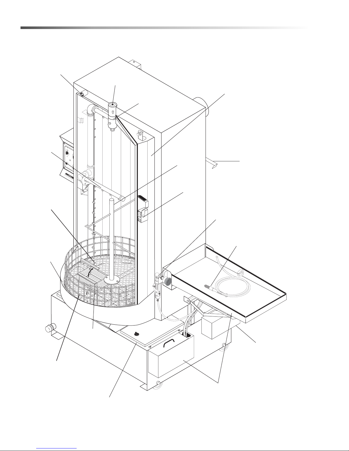
Operations
L
O
W
W
A
TE
R
T
U
RNTABLE
J
OG
W
AS
H
C
YC
LE
6
0
5
0
4
0
3
0
2
0
10
MIN
U
T
E
S
0
2
4
6
8
1
2
10
T
U
R
N
P
A
S
T
2
HEA
TER
0
2
4
6
8
1
2
1
0
T
U
R
N
P
A
S
T
2
O
IL
S
K
IM
M
ER
Door
Switch Rod
Door
Spacer
Door
Spindle
Door
Pa
rts Tree
Power
Brush
(Optional)
Detail
Brush
(Optional)
Oil Drain
Container
Side
Sink/Pump
(Optional)
Sump
Cover
Door
Latch
Small Pa
rts
Basket
Containment
Ring
Turntable
Chain
Turntable
Swing
Do
wn
Spray
old
Sink Tr ay
Latch
(Optional)
Component Identification
Front Options
Manif
10
CUDA 2848 Operator’s Manual 8.930 -369.0 - AG
Page 11
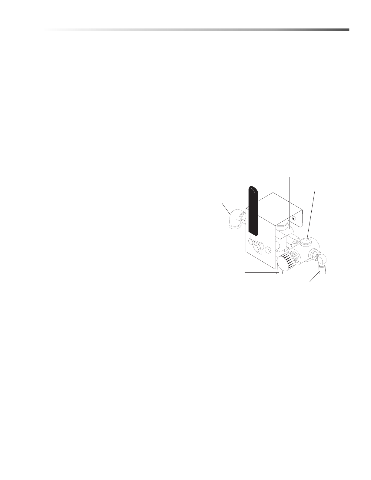
Operations
Outlet to
Power Brush
Air Regulator
3 Way Air
Valve
To
Compressed
Air Supply
Outlet to
Detail Brush
Installation
Before You Begin
To prepare to install the machine, choose an unobstructed, level site that allows convenient access for
operators and maintenance personnel. Sources for
water and electrical power should be located near the
installation site. If your machine is equipped with the
optional power brush and hand detail brush you must
also run a compressed air line to the installation site.
If you have any questions regarding the installation,
please contact your dealer or call a customer service
representative.
When contacting customer service please refer to the
machine identification tag inside the front cover of this
manual for detailed machine specifications.
Step 1: Make Electrical Connections
NOTE: All electrical installation tasks must be
performed by a licensed, professional electrician to
ensure safe and proper operation. The installation
must comply with the National Electric Code and all
applicable state and local codes.
The timer is located below the electrical panel inside
the main electrical enclosure. To configure the timer,
refer to the instruction label inside the timer door.
Step 3: Connect A Compressed-air Line
And Accessories
NOTE: This step is required for machines equipped
with the Deluxe Kit option package. If your machine is
not equipped with the Deluxe Kit option package, skip
the following procedure.
1. Remove the power brush from the box, install the
wire brush in the chuck, and connect the air hose.
2. Familiarize yourself with the three-way air flow
valve, then install a fitting to accommodate a
connection to your compressed-air supply.
The machine can only operate on the type of electrical power indicated on the electrical specifications tag.
Read and understand the electrical specifications tag to
determine the electrical power requirements before
installing the machine.
Step 2: Configure The 24-hour , 7-day
Timers
NOTE: This step is required for machines equipped
with an optional 24-hour, 7-day heater timer or a 24hour, 7-day heater and oil skimmer timer. If your
machine does not have a 24-hour, 7-day timer, skip
this step.
The optional 24-hour, 7-day heater timer controls the
heating system. The optional 24-h our, 7 -day heater and
oil skimmer timer controls the heating system and the
oil skimmer.
The parts washer requires approximately 1 to 2 hours
to heat the wash solution to operating temperature, and
the oil skimmer requires 10 to 15 minutes to effectively
remove oil from the wash solution. Using either timer,
you can schedule the heating system to turn on several
hours before you begin to use the machine each day . In
addition, the optional 24- hour, 7-day heater and oil
skimmer timer allows you to schedule the oil skimmer
to operate while the machine sits idle.
(Optional)
3. Connect the shop compressed-air line to the
machine.
NOTE: To ensure proper operation and to minimize
the possibility of premature component failure, make
sure the compressed air is supplied at 75 to 90 psi.
Manufacturer also recommends an in-line moisture
trap and an in-line lubricator on the main air supply
line. Refer to the documentation provided with the
power brush for more information.
4. Connect the hose from the power brush to the air
flow valve.
5. Hang the power brush on the bracket mounted
along the right side of the machine.
CUDA 2848 Operator’s Manual 8.930 -369.0 - AG
11
Page 12
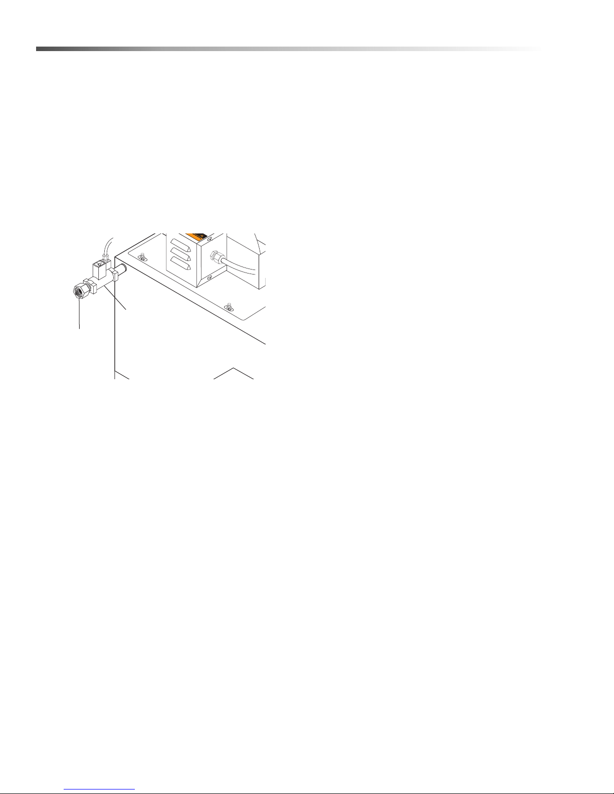
Operations
Fresh
Water In
Solenoid
Valve
Step 4: Connect A Water Line
NOTE: This step is required for machines equipped
with the optional automatic water fill feature. If your
machine does not have this option, skip this step.
The optional automatic water fill feature automatically
maintains the correct water level in the sump. The
feature requires that you connect the machine to a
dedicated water supply line.
To connect the machine to a water supply line , attach a
suitable burst-proof hose to the hose connection on the
rear of the machine below the oil skimmer assembly,
then connect the hose to a nearby water spigot.
3. Turn the heater timer to the 2-hour position. The
sump water will reach operating temperature (160–
180°F) in approximately 1-2 hours.
NOTE: To avoid waiting for the sump water to heat to
operating temperature every day, manufacturer
recommends a 24-hour, 7-day heater timer. With a
24-hour, 7-day timer you can set the heating system
to turn on several hours before you begin to use the
machine each day. For more informatio n ab out 24 hour, 7-day timers refer to 24-hour, 7-day Timers.
4. While the sump water is heating, add the appropriate quantity of factory approved detergent to the
wash chamber. We recommend mixing the
detergent with warm water in a separate bucket/
container and then pouring th e dissolved detergen t
into the sump.
NOTE: Factory approved detergent is the only
detergent approved for use with this automatic parts
washer. It is specially formulated with rust inhibitors
and anti-foaming agents to optimize performance and
minimize maintenance. The use of any other
detergent during the warranty period will void the
warranty. In addition, using factory detergents will
extend your 90 day labor warranty to 1 year.
NOTE: The machine is designed for portability, and
some maintenance tasks require that you move the
machine. DO NOT make a permanent connection
from your shop water supply to the machine.
Step 5: Fill The Machine With Water And
Add Detergent
1. Fill the sump with water. If your machine is
equipped with the automatic water fill feature,
simply open the water inlet valve; if not, add water
through the wash chamber. The sump capacity is
50 gallons.
2. When the sump is full and the low water light has
gone out, shut off the water. If your machine is
equipped with the automatic water fill feature the
water will shut off automatically when the sump is
full.
NOTE: Monitor the water level carefully – do not
overfill the machine. If you overfill the machine,
remove excess water using a small submersible
pump or a suitable container. The correct water level
is two inches from the top of the sump tank when the
pump is off.
5. Close and latch the door.
6. Turn the wash cycle timer to 2 hours for the first
time, and allow the machine to complete the cycle
to thoroughly dissolve the detergent into the water.
7. Deluxe Kit (Optional)
After the machine stops, remove the right sump
cover and transfer approximately two gallons of
wash solution into the detail sump using a small
submersible pump or a suitable container.
WARNING: Hot cleaning solution could cause
serious injury. Always wear rubber gloves and
approved eye protection when handling hot
cleaning solution.
8. Replace all sump covers.
When the machine stops, and after the wash water
reaches operating temperature, it is ready for use.
Refer to Section 3: Operation for complete
operating instructions.
12
CUDA 2848 Operator’s Manual 8.930 -369.0 - AG
Page 13
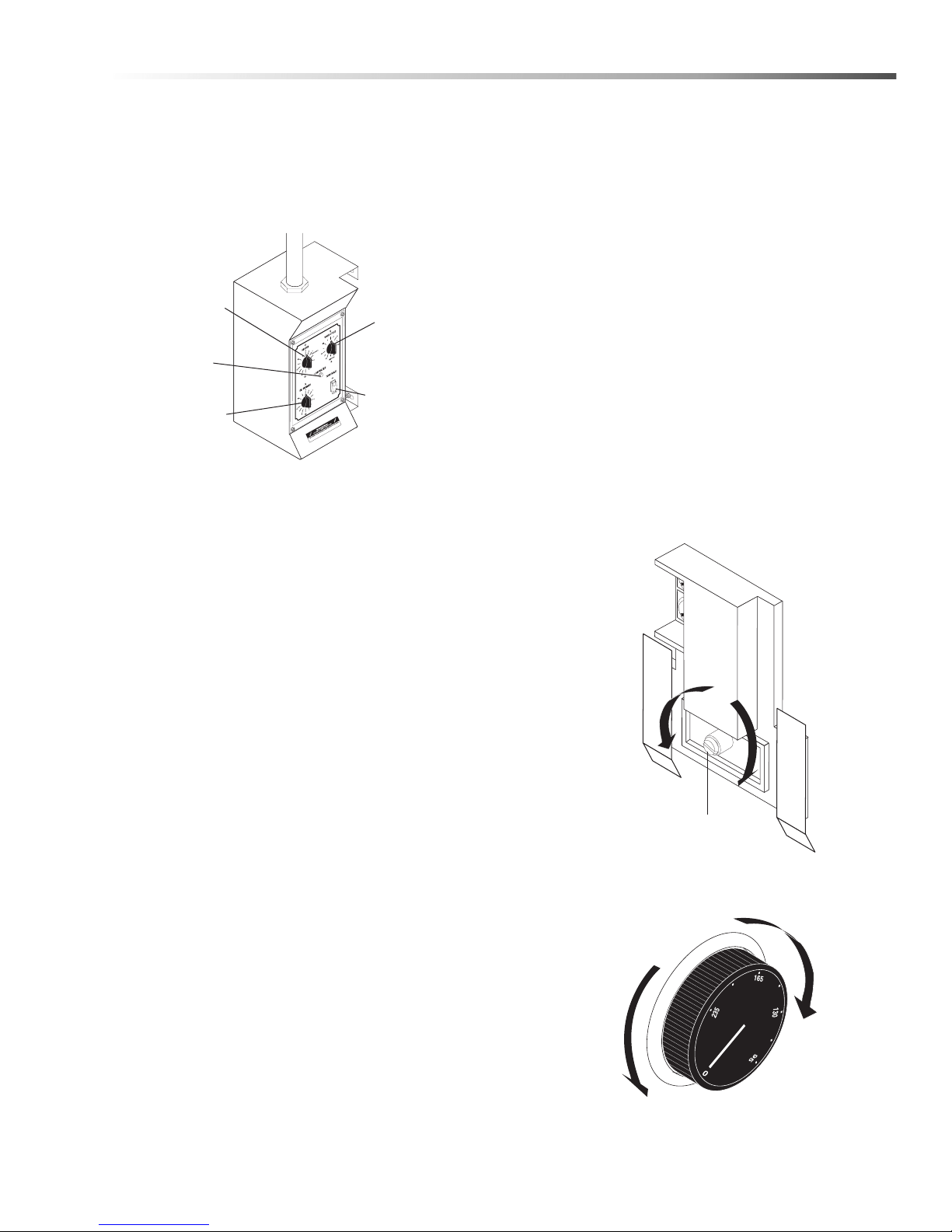
Operations
Three Phase
Adjustment
Screw
Decrease
Temperature
Increase
Temperature
Decrease
Temperature
Increase
Temperature
Heater Control
Oil Skimmer
Control
Low Water
Indicator
Turntab
Switch
Wash Cycle
Control
Main Operating Components
Familiarize yourself with the main operating components before operating the machine.
Control Panel
Heater Control
le Jog
The heater control is a 12-hour timer switch. It controls
the heating element in the sump chamber. The heating
system is thermostatically set at the factory to reach a
high temperature of 180°F. The temperature is adjustable using the thermostat (See Adjusting the Thermo-
stat). The 3-phase units have an adjustable
temperature knob - check temperature setting prior to
use.
Models 2840, 2840, and 2848 machines are available
with a 24-hour, 7-day heater timer or a 24-hour, 7-day
heater and oil skimmer timer . The heater timer con trols
the heating system. The heater and oil skimmer timer
controls the heating system and the oil skimmer.
Thermostat
The thermostat is located inside the heating element
and thermostat enclosure. Single phase thermostats
have an adjustment screw that is accessible only from
inside the enclosure. Three phase thermostats have an
adjustment knob mounted on the outside of the enclosure.
The thermostat is factory-set to heat the wash solution
to a maximum temperature of 180°F.
Adjusting the Thermostat
To adjust the thermostat, rotate the adjustment screw
or knob clockwise to increase the temperature, or
counter-clockwise to decrease the temperature.
Single Phase
Wash Cycle Control
The wash cycle control is a 60-minute timer switch with
a hold feature. When set between 1 and 60 minutes,
the timer automatically shuts off the pump and turntable
when the wash cycle is complete. When set to Hold,
the pump and turntable run continuously until manually
shut off.
Skimmer Control
The skimmer control is a 30-minute timer switch. It
controls the automatic oil skimmer.
Turntable Switch
The turntable switch is a simple rocker switch that
enables you to disconnect power to the turntable motor .
Set to ON, the turntable rotates during the wash cycle.
Set to OFF, the turntable does not rotate during the
wash cycle. The switch is useful for washing large parts
that would otherwise impede turntable rotation.
Low Water Indicator
The low water indicator light illuminates if the wash
solution in the sump is low. For more information refer
to Low Water Shut-off.
24-hour, 7-day Timers
CUDA 2848 Operator’s Manual 8.930 -369.0 - AG
13
Page 14
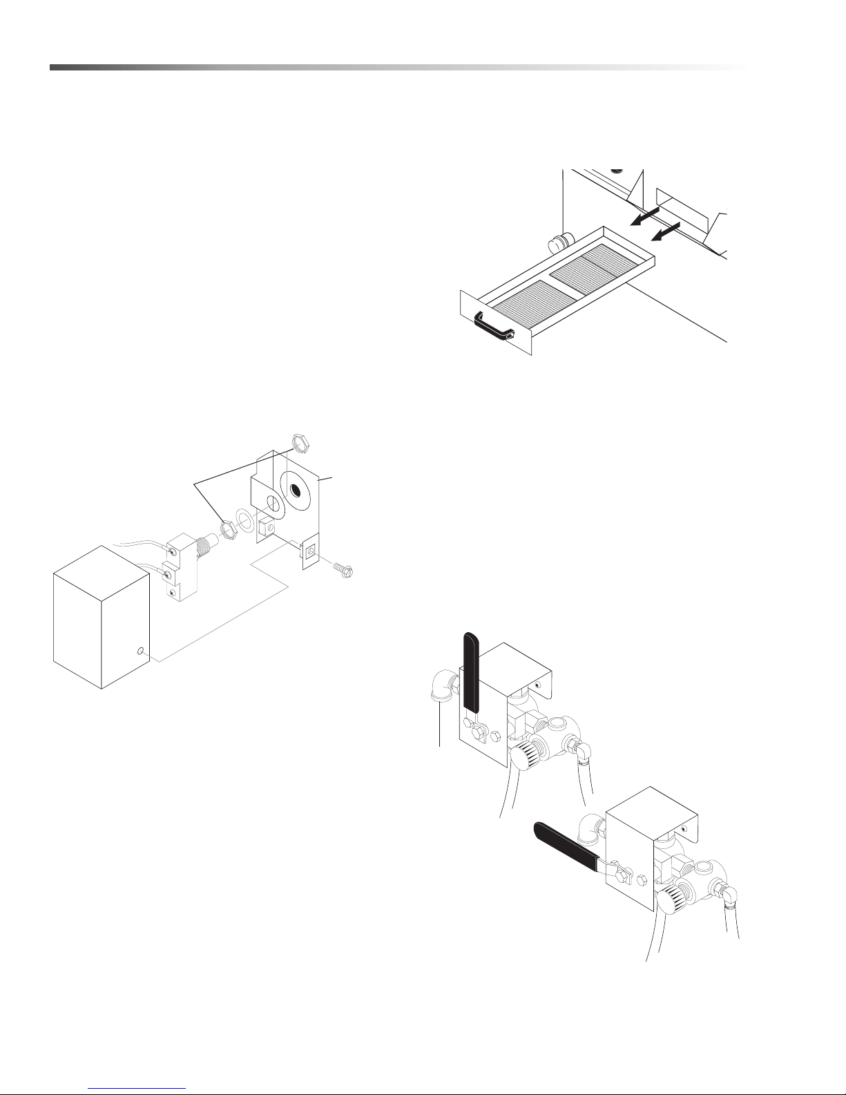
Operations
Switch
Housing
Safety
Switch
Adjustment
Nuts
Switch
Brac
Debris
Screen
To Air
Supply
T
o Air
Suppl
y
Outlet
To Detail
Brush
Outlet
T
o Power
Brush
Position 2:
Detail Brush
Position 1:
Power Brush
Door Safety Switch
The door closure safety switch is located on the rear of
the machine, to the right of the main electrical panel.
The switch is activated with a push-rod that extends
through the wash chamber.
The switch disconnects power to the water pump and
turntable motor if the wash chamber door is opened
during a wash cycle. The water pump and turnta ble
motor will not operate if the door is not closed and
latched correctly.
Adjusting the Safety Switch
1. Disconnect power to the machine.
2. Remove the two screws from the rear of the safety
switch cover, and pull the cover free of the switch
assembly.
3. Loosen the adjustment nuts on both sides of the
switch bracket.
ket
The frequency at which you must clean the debris
screen depends on machine usage. In general, you
should clean the screen before operating the machine
each day.
NOTE: Never operate the machine without the debris
screen in place and never remove the screen while
the machine is operating. The screen is specially
sized to filter particles that could clog the spray
nozzles or damage the water pump.
Operating the machine without the debris screen in
place could cause spray nozzles to clog or the water
pump to fail.
4. Adjust the switch accordingly.
5. Tighten the adjustment nuts.
6. Replace the cover.
When properly adjusted, you should hear a slight
“click” as the door latch engages and compresses
the door seal and the door closure safety switch.
Debris Screen
The debris screen is located just below the wash
chamber, and is accessible from the front of the
machine. The debris screen continuously filters debris
particles from the cleaning solution to ensure blockagefree spray nozzle operation, and also provides a
safeguard against small parts that might accidentally be
washed through from the cleaning chamber.
Air Flow V alve (Optional)
The air flow valve is located on the right rear corner of
the machine. It is a three-way ball valve that controls
the flow of compressed air to the power brush and the
hand detail brush.
14
CUDA 2848 Operator’s Manual 8.930 -369.0 - AG
Page 15
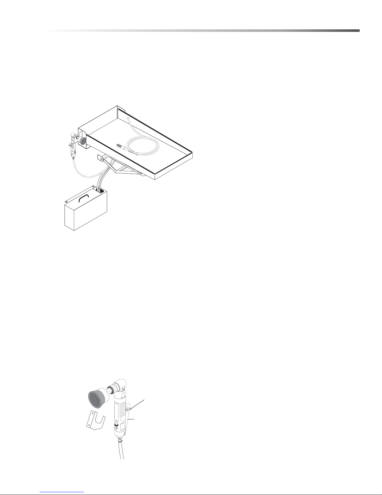
Operations
Fold Do
wn
Detail Tray
Power
Brush
Detail
Sump
Detail
Brush
Holding
Bracket
Throttle
Lever Lock
Throttle Le
vel
Detail Tray and Sump Assembly (Optional)
Detail Tray
The detail tray is located on the right side of the
machine. The tray folds down to provide a convenient
work area for using the power brush and hand detail
brush. The weight capacity of the detail tray is 75
pounds.
Detail Sump
The detail sump is located below the detail tray on the
right side of the machine. It provides wash solution for
the detail brush. The detail sump will hold approximately two gallons of wash solution.
NOTE: The detail tray and sump are standard
components on the Deluxe Kit version of the models
2840 and 2848. They are available as an option on
the base models. To order a Deluxe Kit option
package, contact your distributor or call customer
service.
Power Brush
The power brush is located on the right front corner of
the machine. Refer to Connect a Compressed-Air
Line and Accessor ies for detailed installation information.
(Optional)
NOTE: The power brush is a standard component on
the Deluxe Kit version of the models 2840 and 2848.
It is available as an option on the base models. To
order a Deluxe Kit option package, contact your
distributor or call customer service.
Using the Power Brush
WARNING: Particles dislodged by the power brush
could cause serious injury to your eyes. Always
wear approved eye protection when using the
power brush.
With stiff stainless steel bristles turning at 1800 RPM,
the power brush easily removes carbon depo sits, old
gasket material, or other tightly-ad hered materials from
parts before washing.
To turn on the power brush, position the air flow select
valve appropriately, then push the power brush lever
lock forward with your thumb and squeeze the throttle
lever to control the speed of the brush.
Detail Brush and Flow Regulator
The detail brush is located on the right inside wall of the
detail tray . The flow regulator is lo cated on the right rear
corner of the machine. The detail brush uses a continuous flow of cleaning solution through its nylon bristles
to help you clean delicate or lightly soiled parts. The
flow regulator controls the flow of cleaning solution
through the detail brush.
WARNING: Hot, high-pressured cleaning solution
could cause serious injury. Always wear rubber
gloves and approved eye protection when handling
hot cleaning solution.
Adjusting the Flow of Cleaning Solution
If you need to adjust the flow, pull out the flow regulator
knob, then rotate it clockwise to increase the flow or
counter-clockwise to decrease the flow. After adjusti ng,
push the knob back in to lock it.
NOTE: The detail brush is a standard component on
the Deluxe Kit version of the models 2840 and 2848.
It is available as an option on the base models. To
order a Deluxe Kit option package, contact your
distributor or call customer service.
CUDA 2848 Operator’s Manual 8.930 -369.0 - AG
15
Page 16
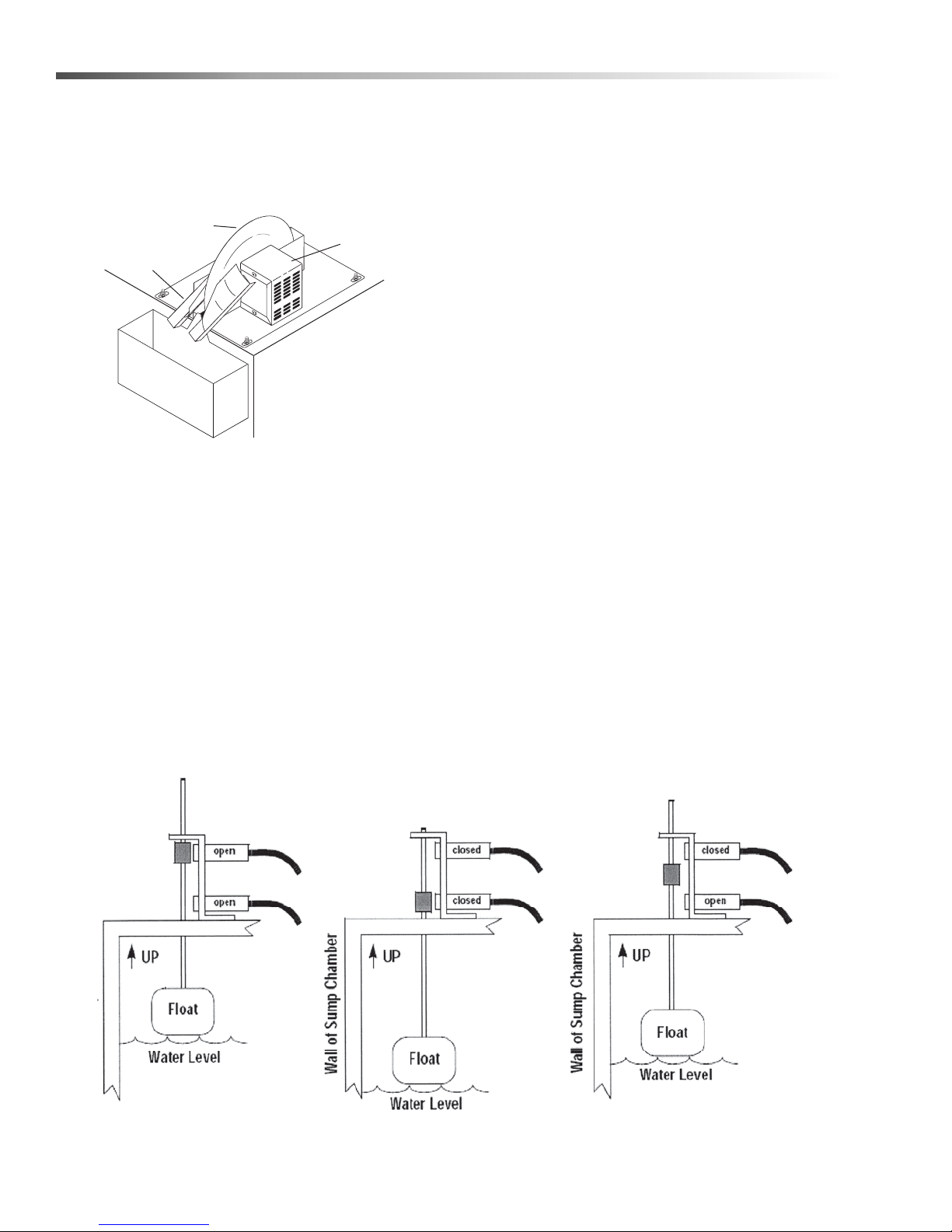
Operations
Skimmer Motor
Skimmer Disk
Wiper Blades
Oil Container
WATER LEVEL OK:
Both Switches OPEN, Automatic
Water Fill Valve (if installed)
CLOSED, Heating Element ON.
LOW WATER LEVEL:
Top Switch CLOSED, Bottom Switch
CLOSED, Automatic Water Fill Valve (if
installed) OPEN, Heating Element O.
SUMP FILLING:
Top Switch CLOSED, Bottom Switch
OPEN, Automatic Water Fill Valve (if
installed) OPEN, Heating Element OFF.
Automatic Water Fill Diagram:
Oil Skimmer
The oil skimmer is located on the right rear corner of
the machine. It automatically removes oil from the wash
solution to prolong its useful life. Refer to Using the Oil
Skimmer for detailed operating instructions.
Water Level
Under typical operating conditions the machine loses
3 to 5 gallons of water per day to evaporation.
It is important that you monitor and maintain the water
level daily to minimize the risk of burning out the
heating element or ruining the pump.
NOTE: Add maintenance detergent each time you
add water. Only add startup detergent after you clean
the sump chamber each month, or your cleaning
cycle maintenance period, if you require a more
frequent cycle, or if you notice specific low-detergent
indicators (See Detergents and Additives).
Automatic Water Fill (Optional)
The optional automatic water fill system automatically
maintains a proper water level in the sump.
The automatic water fill system uses the low water
shut-off proximity switches to open and close a water
solenoid valve, which automatically maintains a proper
water level in the sump. The figure below describes the
operation of the automatic water fill system.
Low Water Shut-off
The low water shut-off system shuts down the machine
if the wash solution in the sump chamber drops below a
safe level. The system uses two proximity switches and
a float rod mounted near the rear of the sump chambe r
to monitor the water level.
If the wash solution drops below the lower proximity
switch, the low water indicator light on the control panel
turns on and the system disconnects power to
machine. To reset the system, add water to the sump
until the low water indicator light turns off.
NOTE: If your machine is equipped with the optional
automatic water fill feature, the sump will
automatically fill when the water level drops below the
lower low water proximity switch.
16
CUDA 2848 Operator’s Manual 8.930 -369.0 - AG
Page 17
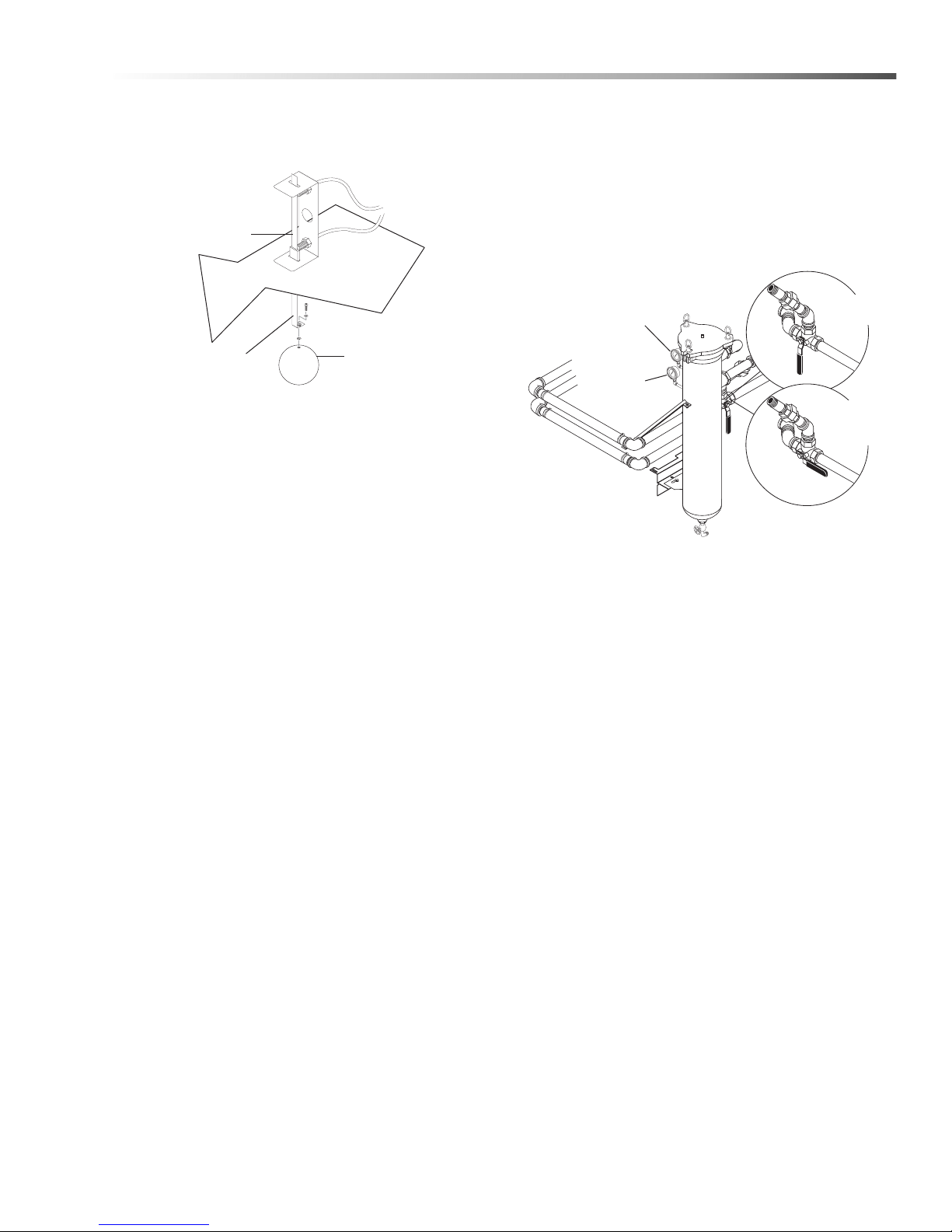
Operations
Float Rod
Float
Proximity
Switches
Inlet
Pressure
Gauge
Outlet
Pressure
Gauge
o Main
Tank
Filter
Sump
Sweep
Position
Wash
Position
Filtration and Sump Sweep Systems
(Optional)
The optional filtration and sump sweep systems reduce
or eliminate the need to manually clean out the sump.
The filtration system continuously filters solid particles
from the wash solution, and you can use the sump
sweep system to periodically remove waste build up
from the bottom of the sump chamber.
Filtration System (Optional)
The filtration system uses a filter canister with a nylon
or polyester felt filter bag to continuously filter solid
particles from the wash solution. The filter system
includes pressure gauges which allow you to monitor
the condition and performance of the filter bag inside
the canister. Under typical operating conditions, the
inlet and outlet pressure gauges read approximately 45
psi. As the filter bag becomes soiled, the outlet
pressure decreases. If the difference between the inlet
and outlet pressure is 15 psi or greater, stop the
machine and clean or replace the filter bag (See
Cleaning the Filters).
WARNING: Operating the machine with a clogged
filter system could damage the filter bag. STOP
THE MACHINE IMMEDIATELY if the difference
between the inlet and outlet pressure is 15 psi or
greater.
CUDA 2848 Operator’s Manual 8.930 -369.0 - AG
Sump Sweep System (Optional)
The sump sweep system uses a three-way valve to
divert solution from the wash chamber to a spray bar on
bottom of the sump chamber. The spray bar generates
a high-pressure spray pattern that agitates the sump
solution and suspends solid particles. The solution then
flows through the filtration system which removes the
solid particles (See Cleaning out the Sump).
T
Detergents And Additives
Manufacturer's detergents are the only detergents
approved for use with our automatic parts washers.
They are specially formulated with rust inhibitors and
anti-foaming agents to optimize performance and
minimize maintenance. The use of any other detergent
during the warranty period will void the warranty.
To monitor the approximate concentration of detergent
in the wash solution, periodically examine the wash
solution in the sump chamber for the following indicators:
• Rust inside the machine: not enough
detergent
• Excessive foaming: not enough detergent
• Thick, white residue on parts after washing:
too much detergent.
To maintain proper concentration under typical conditions, add detergent each month after cleaning the
sump chamber . Follow recommended detergent qu antities. Use a pH kit to determine the proper amount of
detergent to use. If you need help interpreting test
results, contact customer service.
17
Page 18

Operations
Rust Inhibitor Additive
Factory detergents protect the entire inside of your
machine against the degenerative effects of water
evaporation. A rust inhibitor additive actually evaporates with the water and continuously coats and
protects metal surfaces, even while your machine is
sitting idle. For more information, contact your dealer or
call customer service.
Preparing The Machine For Use
Before you begin to wash parts, it is important that you
properly prepare the machine. Before you be gin to u se
the machine each day:
• check the water level and add water to the
sump tank if necessary;
• check sump water cleanliness and run skimmer
as-needed to clean sump water surface;
• heat the water to operating temperature;
• add detergent if necessary (see Detergents);
• verify that none of the spray nozzles are
clogged; and
• clean the debris screen.
and dry before removing them. Most parts will
flash-dry in seconds.
Shutting Down The Machine
To shut down the machine at the end of the day:
• set the wash cycle timer to OFF;
• set the heater timer to OFF; and
• shut off the compressed air at the supply line
(if installed).
WARNING: If the heater is left on unattended, the
wash solution could evaporate and the oil and
grease in the sump chamber could catch fire.
• For periods of extended shut-down, disconnect
all power to the machine. NOTE: Perform rust
preventative treatment on mild steel units prior
to extended storage.
• If your machine is equipped with an optional
24-hour, 7-day heater timer, periodically verify
the settings to prevent inadvertent unattended
operation.
Washing Parts
The following procedure assumes that the heater is on
and the sump water is at operating temperature.
To wash parts, perform the following procedure.
WARNING: Hot, high-pressured cleaning solution
could cause serious injury. Always wear rubber
gloves and approved eye protection when loading
and unloading the machine.
1. Load parts into the machine.
Load large, heavy parts directly onto the turntable.
Secure large, light parts (valve covers for example)
to the turntable using suitable rubber tie-downs.
Load small, light parts into the small parts basket.
NOTE: For optimum cleaning perfor mance, provide a
slight clearance between parts to allow adequate flow
of cleaning solution around and between them.
2. Close and latch the door.
3. Set the wash cycle timer to between 1 and 60
minutes for a timed wash cycle, or set it to Hold for
a continuous wash.
4. When the machine automatically stops (or after
you manually stop the wash cycle), open the door
and wait a few moments to allow the parts to cool
18
CUDA 2848 Operator’s Manual 8.930 -369.0 - AG
Page 19
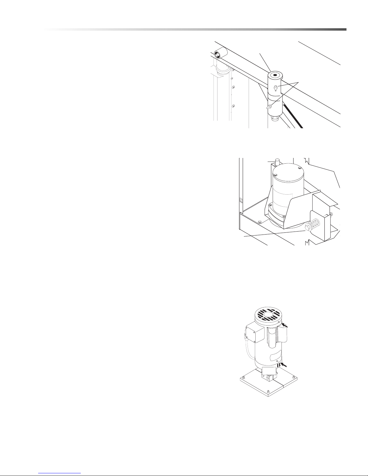
Maintaining The Machine
Door Spindle
Grease Fittings
Grease
Fitting
Grease
Fitting
Pivot Pin
Compression
Spring Assy.
To ensure optimum perfo rmance and trouble-free
operation, observe the following maintenance schedule
consistently.
Daily Maintenance
• Check the water level; add water if necessary.
• Clean the debris screen.
• Remove oil from the wash solution using the oil
skimmer system (See Using the Oil Skimmer
System).
Weekly Maintenance
• Examine the spray nozzles; clean and align if
necessary (See Cleaning and Aligning the
Spray Nozzles).
• Wipe down the exterior of the machine using
degreaser spray and a soft, damp cloth. TO
PREVENT ELECTRICAL COMPONENT
FAILURE, DO NOT SPRAY THE MACHINE
WITH WATER.
• Detergent Concentration Level: Check
detergent level weekly to maintain concentration level which decreases when water is
added. The pH level of this detergent must be in
accordance with the detergent manuf act ur e r's
recommendation.
NOTE: Degreaser spray and a damp cloth will usually
remove all dirt and grime from the machine. For
particularly stubborn soap deposits, use a soft cloth
dampened with warm solution from the wash
chamber.
Monthly Maintenance
• Clean out the sump chamber and detail sump
(See Cleaning out the Sump).
• Lubricate the door spindle using high-quality
automotive grease. Add grease until it begins to
flow out of the joint beneath the grease fitting,
then wipe excess grease from the fitting and the
joint.
Maintenance
Semi-Annual Maintenance
• Lubricate the pivot pin on the turntable
motor assembly with machine oil or anti-seize.
• Lubricate the upper and lower pump bearings
using high-quality automotive grease. Do not
over grease the bearings; over greasing could
cause premature failure.
• For 5-HP pumps, add 1–2 strokes of grease
every six months; for pumps larger than 5-HP,
add 2–3 strokes of grease every year.
CUDA 2848 Operator’s Manual 8.930 -369.0 - AG
19
Page 20
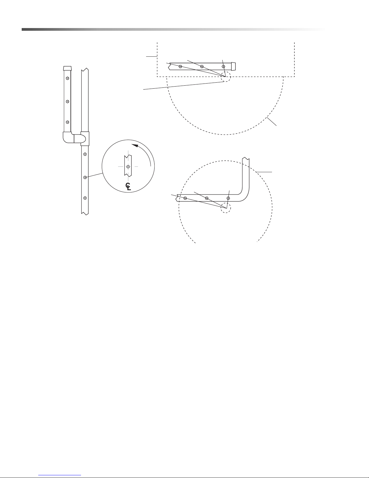
Maintenance
Align the notch in each
spray nozzle with the
center of the turntable.
Rotate each nozzle
approximately 3° from the
centerline of the pipe.
BOTTOM NOZZLES
SIDE NOZZLES
TOP NOZZLES
3°
Turntable
Door
Cabinet
Pivot
Assy.
Align the notch in each
spray nozzle with the
center of the door pivot
assembly.
Cleaning and Aligning the Spray Nozzles
To ensure optimum cleaning performance, it is
important that you examine the spray nozzles periodically and clean and align them if necessary.
To clean a plugged nozzle, remove it from the spray
pipe and use a small wire brush to free the nozzle of
any obstructions. When you replace the nozzle on the
spray pipe, make sure you align it according to the
figure on top of the following page to maintain a proper
spray pattern.
NOTE: The spray nozzles are sized and positioned to
optimize the distribution of cleaning solution in the
wash chamber. If you remove the nozzles make sure
you replace them in the correct position on the
appropriate pipe.
Using the Oil Skimmer System
The oil skimmer system is most effective if used when
the cleaning solution in the sump is cool.
The frequency at which you must remove the oil from
the wash solution will depend on machine usage.
Under typical operating conditions you may need to
remove the oil every day. If the oil skimmer runs lo nger
than 10-15 minutes, the detergent and vapor rust
inhibitor content in the sump should be checked. The
detergent and inhibitor can be removed with extensive
use of the skimmer, so be certain to check chemical
levels after running the skimmer to determine if you
require a higher frequency chemical maintena nce cycle
than weekly.
IMPORTANT: The skimmer motor is equipped with a
thermal overload switch which protects the skimmer
from overheating. If you attempt to use the oil skimmer
system when the wash solution is hot, the thermal
overload will probably trip and the motor will shut off
until it cools. Under normal skimming conditions (when
the wash solution is cool) the thermal overload should
not trip.
20
CUDA 2848 Operator’s Manual 8.930 -369.0 - AG
Page 21
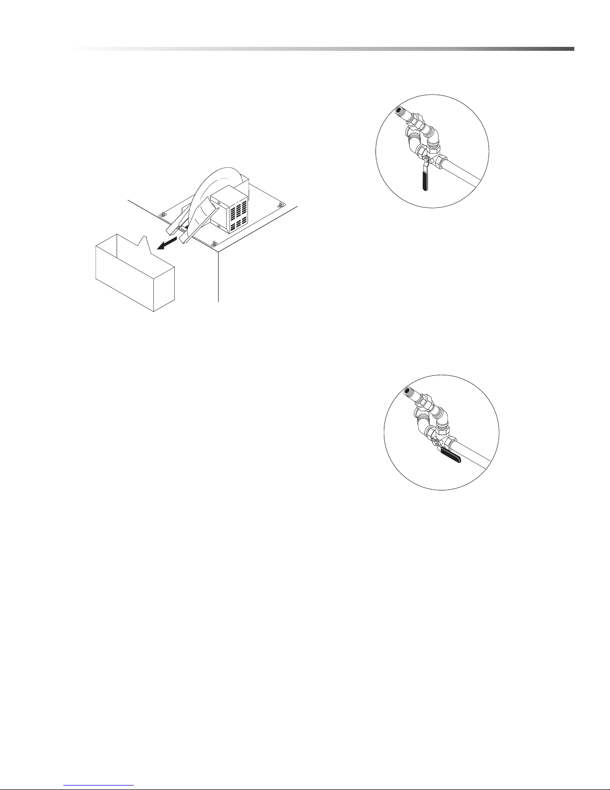
Maintenance
Oil Skimmer
Assy.
Wash
Position
Sump
Sweep
Position
To remove oil from the cleaning solution, perform the
following procedure:
1. Allow the machine to sit idle for at least 30 minutes
to allow the oil to float to the surface of the wash
solution.
2. Ensure that the oil collection container is in place,
then turn the skimmer switch to the “ON” position.
Oil Container
3. Allow the oil skimmer to operate until it is no longer
extracting oil from the cleaning solution.
TIP: While extracting oil from the cleaning solution, oil
will flow off the wiper blades in a fine continuous
stream. Water will flow off the blades in droplets. Once
droplets begin to flow off the wiper blades, stop the
skimmer motor.
3. Position the three-way wash solution valve as
shown.
4. Close and latch the door.
5. Run the machine through a 30-minute was h cyc le.
NOTE: While the sump sweep is operating, monitor
the outlet pressure on the filter system to ensure that
it does not drop below 30 psi. If the pressure drops
below 30 psi, immediately stop the machine and
either clean or replace the filter bag( s) (See Cleaning
the Filters).
6. After the machine stops, position the three-way
wash solution valve as shown.
4. Dispose of the oil in the collection container in
accordance with local and state regulations, then
replace the container.
Cleaning out the Sump
Filtration and Sump Sweep System
NOTE: The effectiveness of the filtration and sump
sweep system for cleaning out the sump will depend
on the type of filter bag(s) you use in the filter
canister(s). If you find that the filtration and sump
sweep systems do not adequately clean the sump on
your machine, contact your dealer or customer
service for other filter bag recommendations.
To clean out the sump using the optional filtration
and sump sweep system, perform the following
procedure:
1. If your machine is equipped with a detail sump,
dump the contents of the detail sump into the main
sump chamber.
2. Remove oil and grease from the cleaning solution
using the oil skimmer system (See Using the Oil
Skimmer System).
7. Add the appropriate amount of detergent and run
the machine through a 30-minute wash cycle. Use
a pH kit to determine the proper amount of
detergent to add.
NOTE: Our detergent is the only detergent approved
for use with our automatic parts washers. It is
specially formulated with rust inhibitors an d an tifoaming agents to optimize performance and
minimize maintenance. The use of any other
detergent during the warranty period will void the
warranty.
CUDA 2848 Operator’s Manual 8.930 -369.0 - AG
21
Page 22
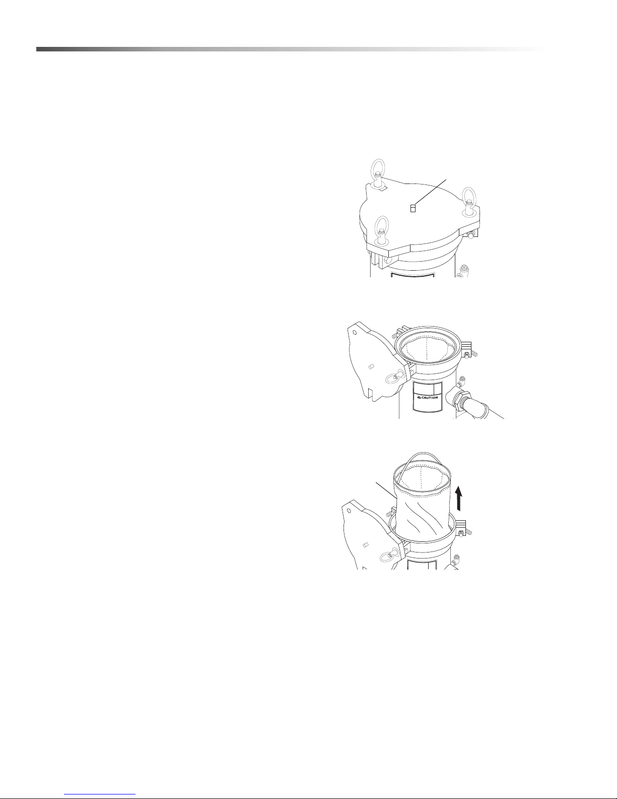
Maintenance
Pressure
Release Plug
Filter
Lid
Filter Bag
Manual Sump Clean out
To manually clean out the sump, perform the following
procedure:
1. If your machine is equipped with a detail sump,
dump the contents of the detail sump into the main
sump chamber.
2. Remove oil and grease from the cleaning solution
using the oil skimmer system (See Using the Oil
Skimmer System).
3. If your machine is equipped with the Auto-Fill
feature, turn off the water at the supply line.
4. Remove both sump covers, then drain the wash
solution from the sump chamber. To drain the
solution either use the sump drain or a small
submersible pump.
5. Remove sand and other debris from the bottom of
the sump chamber and the detail sump. To remove
the debris, either flush it out through the sump
drain or vacuum it out using a wet/dry vac. Dispose
of the debris in accordance with applicable local,
state, and federal regulations.
1. Turn off the machine and open the door.
2. If your machine is equipped with the Auto-Fill
feature, turn off the water at the supply line.
3. Slowly unscrew the pressure-release plug on the
lid of the filter canister to release the pressure in
the filtration system.
4. Loosen the three lid nuts, then swing the lid fre e of
the canister.
NOTE: Take special care to ensure that the heat ing
element is free of debris. A buildup of debris around
the element will decrease heating performance and
may cause the element to overheat and fail.
6. Refill the sump with fresh clean water.
7. Replace the sump covers and heat the wash wa ter
to operating temperature.
8. Add the appropriate amount of detergent and run
the machine through a 30-minute wash cyc le . Use
a pH kit to determine the proper amount of
detergent to use.
NOTE: Our detergent is the only detergent approved
for use with our automatic parts washers. It is
specially formulated with rust inhibitors and antifoaming agents to optimize performance and
minimize maintenance. The use of any ot he r
detergent during the warranty period will void the
warranty.
Cleaning the Filters
Our filtration systems are available in single or multiple
canister configurations. Each canister uses a nylon or
polyester felt filter bag to remove solid particles from
the wash solution. Nylon bags are reusable; polyester
felt bags are designed for a single use. To clean or
replace the filters, perform the following procedure:
5. Remove and empty the filter bag and screen.
6. If you are using a nylon filter bag, you can clean
and reuse it several times before replacing it. If you
are using a polyester felt filter bag, you must
replace it. Contact your dealer or call customer
service for filter bag recommendations and
ordering information.
7. Replace screen and filter bag in the filter canister.
8. Install and tighten the lid.
9. Tighten the pressure-release plug.
10. Turn on machine and continue washing.
22
CUDA 2848 Operator’s Manual 8.930 -369.0 - AG
Page 23
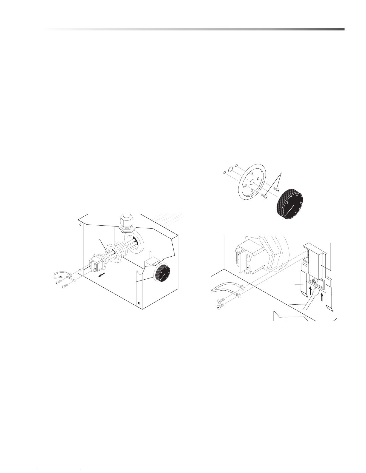
Maintenance
P
ower
Leads
Heating
Element
Thermostat
Screws
THREE PHASE
Screwdriver
Power
Leads
Thermostat
Mounting
Bracket
Repairing The Machine
The following procedures outline the steps necessary
to replace specific items on the machine that could
wear out or otherwise fail.
Heating Elements
Required Tools and Equipment
• 5/16” wrench or socket
• 2” socket and breaker bar
• sealing tape or compound
• medium phillips-head screwdriver
Replacement Procedure
1. Disconnect power to the machine.
2. Drain the wash solution from the sump.
3. Remove the cover from the heating element and
thermostat enclosure (two 5/16” screws).
4. Detach the power leads from the heating elements,
taking care to mark them for reassembly.
Thermostat
Required Tools and Equipment
• 5/16” wrench or socket
• medium phillips-head screwdriver
• large flat-head screwdriver
Replacement Procedure
1. Disconnect power to the machine.
2. Remove the cover from the heating element and
thermostat enclosure (two 5/16 ” scr ews).
3. Remove the thermostat knob and the two screws
to remove the thermostat from the housing.
5. Using a 2” socket and breaker bar, unscrew the
heating element(s) from the machine.
NOTE: Since the heating element is in continuous
contact with the cleaning solution the threads may
corrode slightly. The element may be difficult to
remove. When you install a new heating element, use
sealing tape or compound on the threads to deter
corrosion.
6. Install the new heating element(s). Installation is
the reverse of removal.
4. Detach the electrical leads from the thermostat.
5. Remove the thermostat from the machine.
6. Install the new thermostat. Installation is the
reverse of removal.
CUDA 2848 Operator’s Manual 8.930 -369.0 - AG
23
Page 24
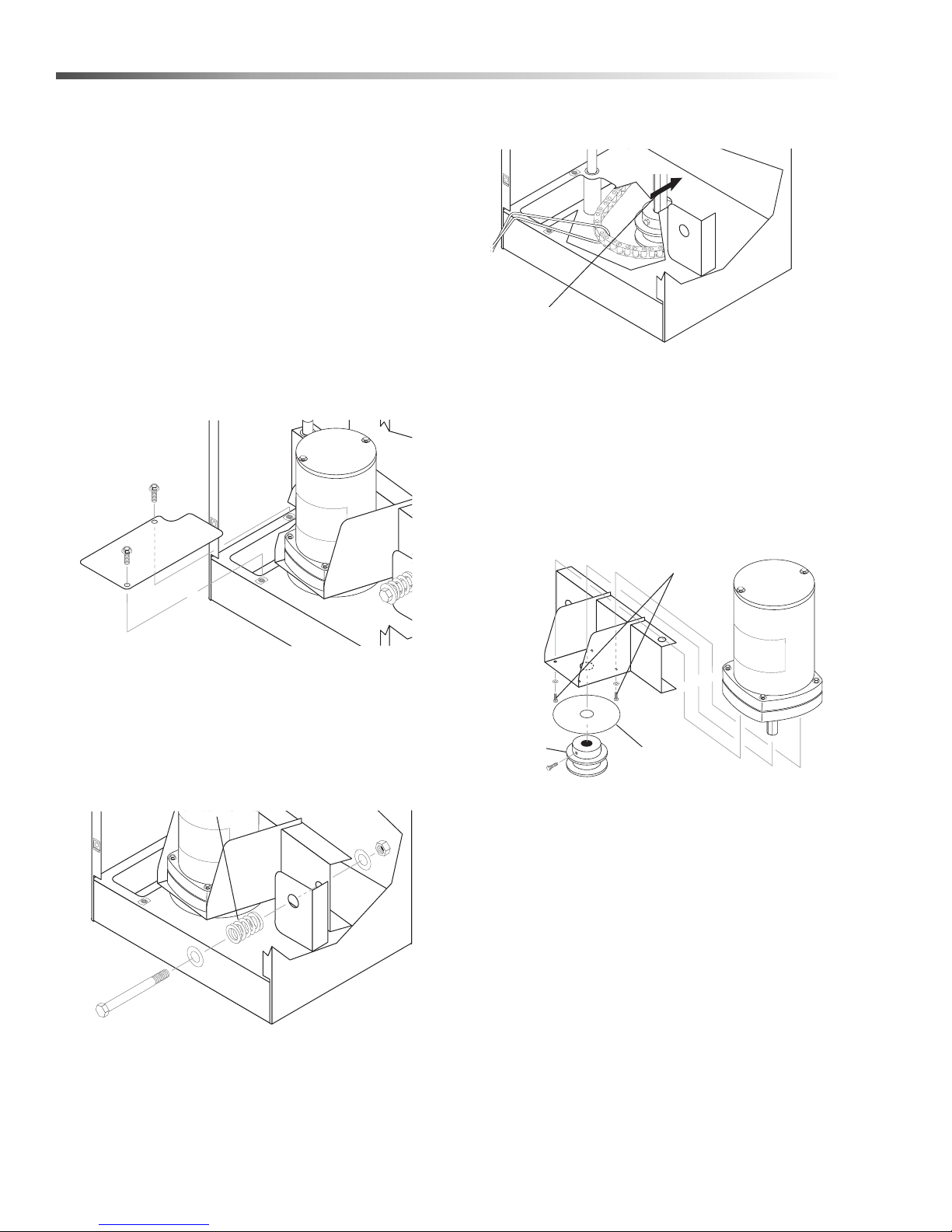
Maintenance
Drive Pull
ey
Access
Compression
Spring
Motor Pulley
Hex Bolt
Steam
Shield
Disk
Screws
Turntable Motor
Required Tools and Equipment
• 5/16” wrench or socket
• 1/8” hex key
• medium phillips-head screwdriver
Replacement Procedure
1. Disconnect power to the machine.
2. Remove the main electrical panel cover (eight
screws; use a 5/16” wrench or socket). The
turntable motor assembly is located just below the
electrical panel.
3. Remove the drive pulley access plate.
the wash chamber. Use a piece of wire to secure
the chain while you replace the motor.
6. Disconnect all power leads from the motor, taking
care to mark them for reassembly.
7. Raise the motor and bracket to remove the
assembly from the pivot pin.
8. Use a 3/32” hex key to remove the pulley and
steam shield disk from the drive motor shaft, then
remove the four mounting screws holding the
motor to the mounting bracket.
Mounting
To remove the plate, remove the two screws using
a 5/16” wrench or socket, then slide the plate
toward the rear of the machine through the slot in
the housing.
4. Remove the compression spring from the motor
assembly using a 9/16” wrench and socket.
5. Push the motor assembly toward the front of the
machine, then reach into the drive pulley access
hole with your fingers to free the chain from the
drive pulley. Take care not to let the chain slip into
9. Install the new motor. Installation is the reverse of
removal.
Timers and Switches on the Control Panel
Required Tools and Equipment
• 5/16” wrench or socket
• 1/2” wrench or deep socket
• small phillips-head screwdriver
• small flat-head screwdriver
Replacement Procedure
1. Disconnect power to the machine.
24
CUDA 2848 Operator’s Manual 8.930 -369.0 - AG
Page 25
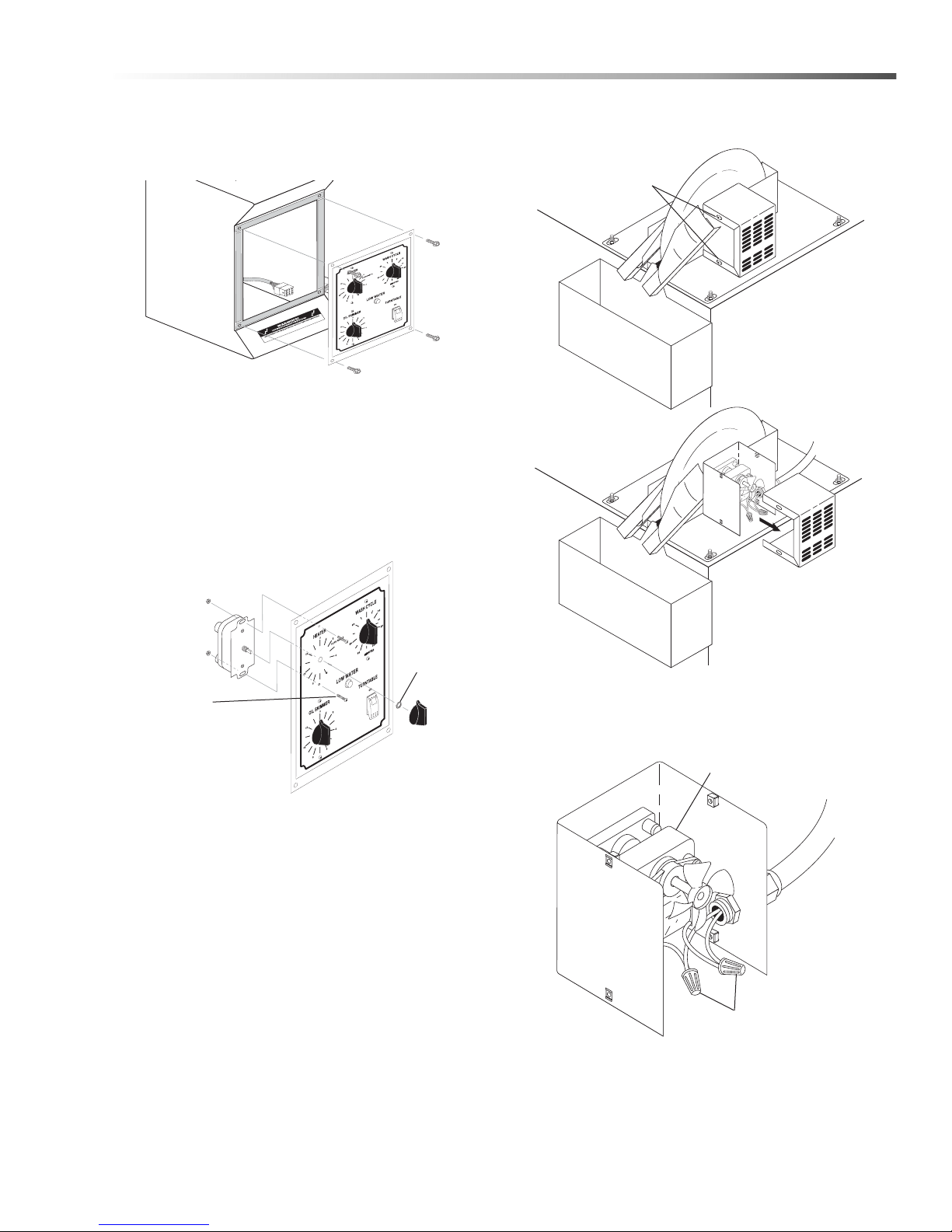
Maintenance
Scr
ews
Knob
Retaining
Nut
Screws (Two on
Each Side)
Slide Cover
Toward Rear
to Remove
Wire Nuts
Oil Skimmer
Motor
2. Remove the control panel face plate
(four 10/32” screws).
3. Disconnect the wiring harness from the rear of the
face plate.
4. Remove the knob from the timer you wish to
remove.
5. Remove the two screws, retaining nut, and o-ring
that hold the timer switch to the control panel.
2. Remove two 5/16” screws to remove the skimmer
motor cover.
6. Detach the power leads from the timer.
7. Attach the power leads to the new timer.
8. Install the new timer. Installation is the reverse of
Oil Skimmer Motor
Required Tools and Equipment
Replacement Procedure
1. Disconnect power to the machine.
3. Remove the two wire nuts from the power leads to
disconnect the leads from the motor, and disconnect the conduit from the motor housing.
removal.
• •5/16” wrench or socket
• • 1/2” wrench or socket
• • small phillips-head screwdriver
CUDA 2848 Operator’s Manual 8.930 -369.0 - AG
25
Page 26
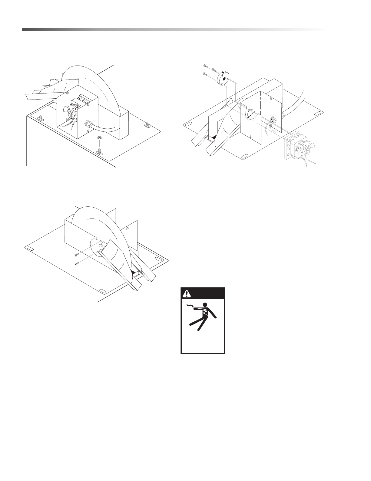
Maintenance
Nut
Screws
DANGER
KEEP WATER
SPRAY AWAY FROM
ELECTRICAL WIRING.
4. Remove the four 1/2” bolts from the skimmer
assembly mounting plate to remove the skimmer
assembly from the machine.
5. Remove the two screws from the center of the
skimmer disk to detach the disk from the skimmer
assembly. To remove the disk, disengage it from
the center pin, then slide it down.
6. Remove the three screws from the skimmer motor
mounting plate to remove the motor from the
skimmer assembly.
7. Reassemble the skimmer assembly and replace it
on the machine. Assembly is the re verse of
removal.
Troubleshooting
Troubleshooting the Electrical System
To troubleshoot the electrical system use the following
diagrams to eliminate the possibility of a blown fuse or
a bad connection, then refer to Testing Individual
Components to determine which component is causing
the problem.
DANGER: Keep water away from
electric wiring or fatal electric
shock may result.
• Electrical troubleshooting should be performed
by qualified personnel only.
• Avoid contact with power leads, terminals and
fuses when power is connected.
• Disconnect power to machine before removing
fuses or other electrical components.
26
CUDA 2848 Operator’s Manual 8.930 -369.0 - AG
Page 27
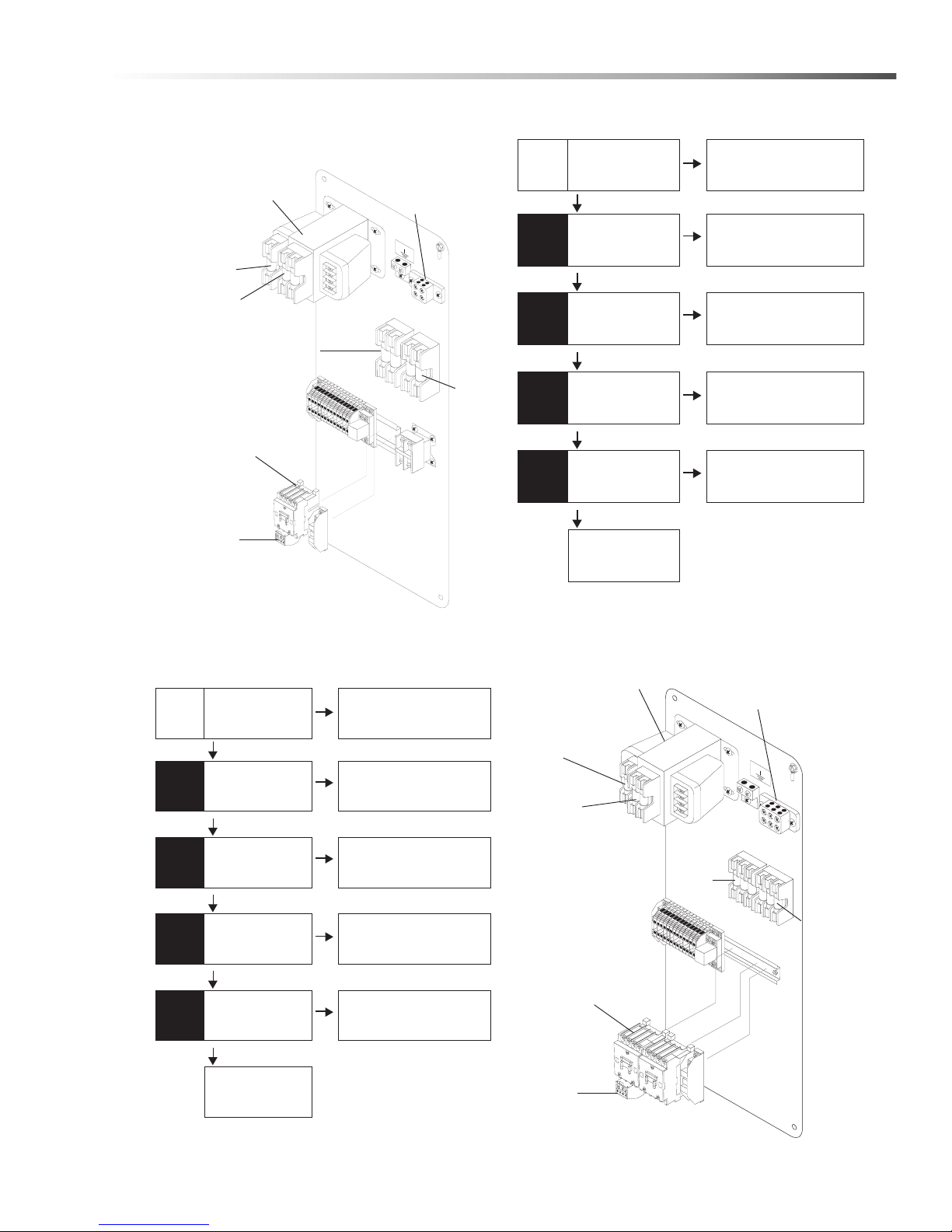
T roubleshooting a Single Phase Panel
f
f
f
f
None
Power
ON
Power
OFF
Power
OFF
Power
OFF
Power
OFF
Measure Voltage Across
L1, and L2 Terminals on
Junction Box
Electrical Panel is OK,
Check Main Power
Disconnect
Remove Primary Fuses;
Measure the Resistance
of Each
Fuse is Blown; Replace
Blown Fuse
Remove Secondary
Fuse; Measure the
Resistance
Secondary Fuse is
Blown; Replace Fuse
Remove Heater Fuses;
Measure the Resistance
of Each
One of the Heater Fuses
is Blown; Replace the
Blown Fuse
Remove Pump Fuses;
Measure the Resistance
of Each
One of the Pump Fuses
is Blown; Replace the
Blown Fuse
Electrical Panel is
OK, Refer to Testing
Individual Components
208 to 240V
approximately 0 Ohms
approximately 0 Ohms
approximately 0 Ohms
approximately 0 Ohms
G
R
O
U
ND
Junction
Block
Transformer
Secondary
Fuse
Primary
Fuses
Heater
Fuses
Pump
Fuses
Pump
Contactor
Pump
Overload
Relay
f
f
f
f
None
Power
ON
Power
OFF
Power
OFF
Power
OFF
Power
OFF
Measure Voltage
Across L1, L2 and L3
Ter minals on Junction
Box
Electrical Panel is OK,
Check Main Power
Disconnect
Remove Primary
Fuses; Measure the
Resistance of Each
Fuse is Blown; Replace
Blown Fuse
Remove Secondary
Fuse; Measure the
Resistance
Secondary Fuse is
Blown; Replace Fuse
Remove Heater
Fuses; Measure the
Resistance of Each
One of the Heater Fuses
is Blown; Replace the
Blown Fuse
Remove Pump
Fuses; Measure the
Resistance of Each
One of the Pump Fuses
is Blown; Replace the
Blown Fuse
Electrical Panel is
OK, Refer to Testing
Individual Components
208 to 240V
approximately 0 Ohms
approximately 0 Ohms
approximately 0 Ohms
approximately 0 Ohms
GROU
N
D
Junction
Block
Transformer
Secondary
Fuses
Primary
Fuses
Heater
Fuses
Pump
Fuses
Pump
Overload
Relay
Pump
Contactor
Maintenance
T roubleshooting a Three Phase Panel
CUDA 2848 Operator’s Manual 8.930 -369.0 - AG
27
Page 28
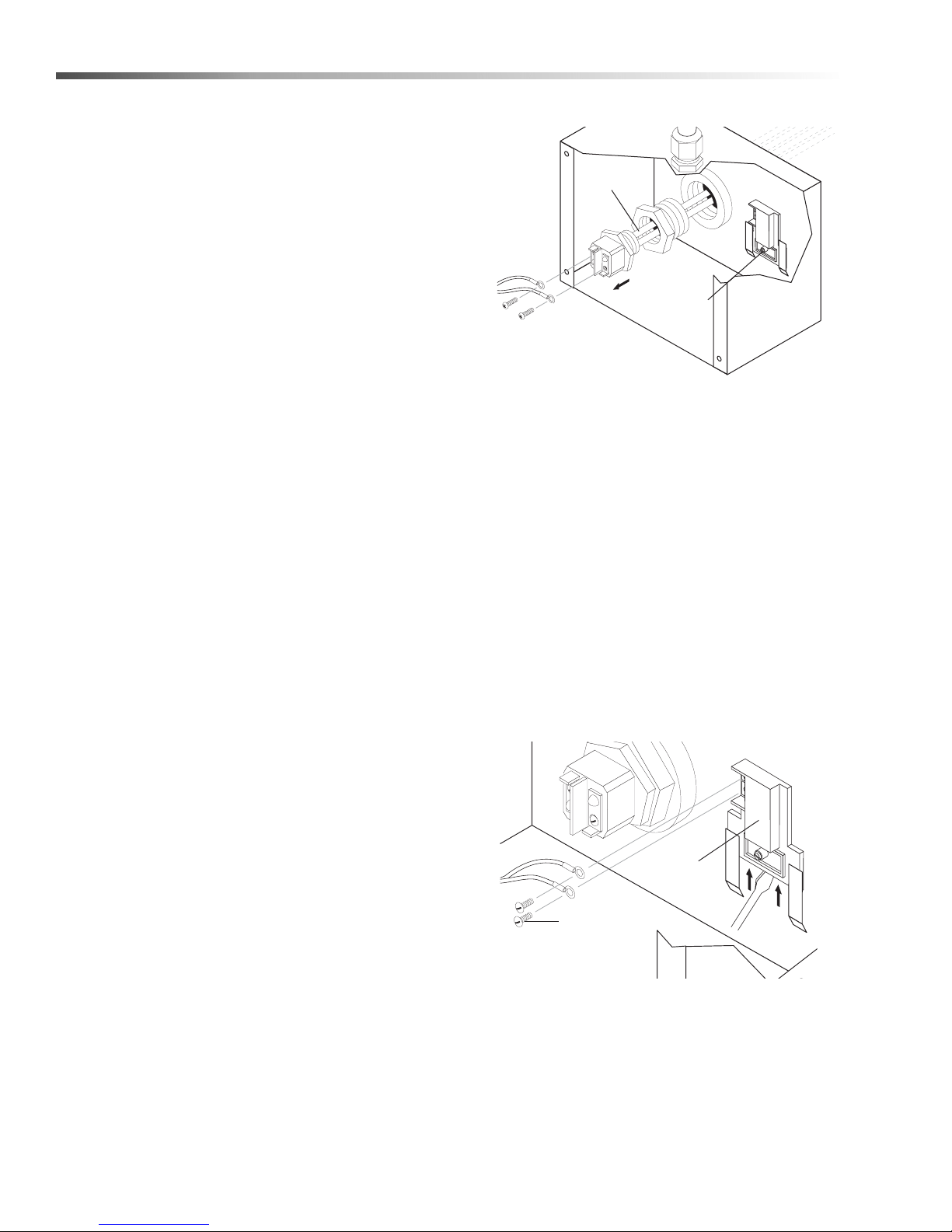
Maintenance
Heating
Elements
P
ower Leads
Thermostat
ower
Thermostat
Screw
Testing Individual Components
NOTE: The following troubleshooting procedures
require the use of a volt/ohm meter. If you are not
familiar with using a volt/ohm meter do not attempt to
perform the following troubleshooting procedures. If
you need assistance please contact your de ale r or
call a customer service representative.
Wash Cycle, Heater, And Oil Skimmer
Timers
1. Disconnect power to the machine.
2. Remove the timer from the control panel and
disconnect all wires (See Timers and Switches
on the Control Panel).
3. With the timer in the OFF position, test for conti-
nuity using an ohm meter.
If there is continuity the timer is no longer functional; replace the timer.
4. With the timer in the ON position, test for continuity
using an ohm meter.
If there is not continuity the timer is no longer functional; replace the timer.
3. Detach the power leads from the heating element.
4. Use an ohm meter to measure the resistance of
the heating element. The single-phase resistance
should be approximately 10 Ohms; if not, replace
the heating element (See Heating Element).
Three Phase Heating Element
A three phase heating element is a complex component. Please contact your customer service representative for testing instructions.
Door Safety Switch
1. Disconnect power to the machine.
2. Remove the switch from the rear of the machine
and disconnect all wires (See Door Safety
Switch).
3. With the switch fully open (not depressed), test for
continuity.
If there is continuity the switch is no longer functional; replace the switch.
4. With the switch fully closed (depressed), test for
continuity.
If there is not continuity the switch is no longer
functional; replace the switch.
Single Phase Heating Element
1. Disconnect power to the machine.
2. Remove the cover from the heating element and
thermostat enclosure (four screws; use a 5/16”
wrench or socket).
Single Phase Thermostat
1. Disconnect power to the machine.
2. Remove the cover from the heating element and
thermostat enclosure (four screws; use a 5/16"
wrench or socket).
3. Detach the power leads from the thermostat.
P
Leads
4. Using a large flat-head screwdriver, pry the thermostat out of the mounting bracket, then remove it
from the machine.
5. Set the thermostat to 120°F, warm it to just above
120°F, then test for continuity.
28
CUDA 2848 Operator’s Manual 8.930 -369.0 - AG
Page 29
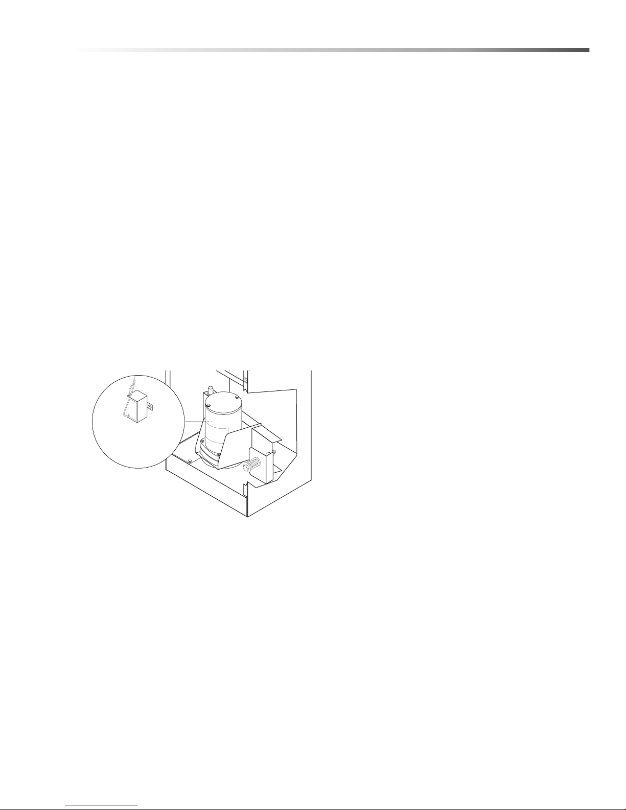
If there is continuity, the thermostat is no longer
Start
Capacitor
functional; replace the thermostat.
6. Allow the thermostat to cool to room temperature,
then test for continuity.
If there is not continuity the thermostat is no longer
functional; replace the thermostat.
Three Phase Thermostat
A three phase thermostat is a complex component.
Please contact your customer service representative
for testing instructions.
Start Capacitor
1. Disconnect power to the machine.
2. Remove the main electrical panel cover (eight
screws; use a 5/16” wrench or socket). The
turntable motor assembly is located just below the
electrical panel.
3. Visually inspect the start capacitor. If it appears
swollen or deformed, it is no longer functional;
replace the start capacitor.
Maintenance
4. If the start capacitor is not visibly failed, remove it
from the motor bracket, disconnect the wires, and
test it for shorts using an ohm meter.
If the ohm meter reads approximately 1 Ohm, the
start capacitor is no longer functional; replace the
start capacitor.
CUDA 2848 Operator’s Manual 8.930 -369.0 - AG
29
Page 30
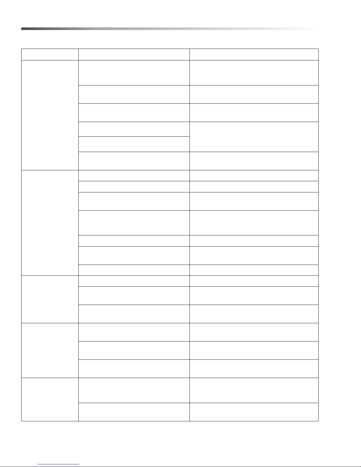
Maintenance
PROBLEM POSSIBLE CAUSE SOLUTION
Check the position of parts on turntable;
Parts are obstructing each other
position parts to allow flow of cleaning
solution around and between them.
POOR
CLEANING
PERFORMANCE
WASH
SOLUTION
IS NOT
HEATING
Low water level in sump
Clogged or improperly aligned spray
nozzles
Wash solution is not properly heated
Low detergent concentration
less than 9 pH. Should be 10-11 pH
Pump is not operating properly
Blown fuse Check the electrical panel for a blown fuse.
Thermostat is set incorrectly Check the thermostat setting; set to 180°F.
Line voltage is too low
Excess debris is built up around
heating element
Failed heat timer Test the heater timer; replace if necessary.
Failed thermostat
Check sump water level and add water
if necessary.
Check the spray nozzles for obstructions
and alignment; clean and align if necessary.
Check wash solution temperature; temperature
should be between 160°F and 180°F (See
Wash Solution Is Not Heating Section)
See Pump Does Not Operate Properly
section.
Contact a licensed electrician to verify that
the line voltage matches unit voltage.
Check for debris build up around the heating
element; clean out if necessary.
(See Cleaning Out the Sump Section).
Test the thermostat; replace if necessary
(See Thermostat Section).
FOAMING
WHITE
POWDER
ON PARTS
WASH
SOLUTION
IS TOO HOT
Failed heating element Test the heating element; replace if necessary.
Machine operating with cold water Bring water up to correct temperature.
Grease, high detergent motor oils, trans-
mission oils, synthetic oils, gear lubes,
Not enough detergent
Solution is old
Water hardness and TDS
(totally dissolved solids)
Large parts can dry before solution runs
off, leaving powdery residue
Thermostat is incorrectly installed
Failed thermostat
Do not place oil pan or transmission pan.
Add more detergent,
check pH level. Use defoamer.
Change sump water and recharge with
fresh detergent and vapor corrosion inhibitor.
Use a water softener and/or change
your sump water more frequently.
Monitor soap concentration and correct as
needed.
Check the thermostat to ensure that it
is correctly installed into the mounting
bracket. (See Thermostat Section).
Replace the thermostat
(See Thermostat Section).
30
CUDA 2848 Operator’s Manual 8.930 -369.0 - AG
Page 31
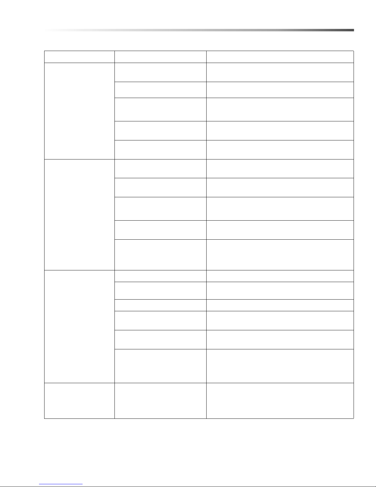
PROBLEM POSSIBLE CAUSE SOLUTION
Maintenance
MACHINE FAILS TO
START WHEN
“WASHING PARTS”
PROCEDURE IS
FOLLOWED
TURNTABLE
DOES NOT
OPERATE
PROPERLY
Main power disconnect is off
Lid/door is not closing
properly
Failed lid/door closure safety
switch
Failed washer cycle timer
Pump is not operating
properly
Parts are obstructing turntable
rotation
Drive chain is not on the drive
pulley
Turntable motor compression
springs are not installed
Blown fuse
Failed wash cycle timer
Low water level in sump Check sump water level; add water if necessary.
Verify that no service is being performed on the
machine, then turn the main power disconnect on.
Check the lid/door closure safety switch; adjust
if necessary.
Test the lid/door closure safety switch; replace if
necessary (See Adjusting the Lid/Door Safety
Switch).
Test the wash cycle timer; replace if necessary (See
Lid/Door Safety Switch).
See Pump does not operate properly section.
Check for parts obstructing rotation
of the turntable; rearrange if necessary.
Check drive chain; realign
on drive pulley if necessary.
Check the turntable motor compression
springs; install if necessary
(See Turntable Motor Assembly).
Check electrical panel for blown
fuse; replace if necessary.
Test the electrical panel to eliminate the
possibility of a blown fuse then contact
a licensed electrician or a service
representative to test the turntable motor.
PUMP DOES
NOT OPERATE
PROPERLY
OIL SKIMMER
DOES NOT
OPERATE
PROPERLY
Pump intake is plugged
Pump overload relay is tripped Reset the motor overload relay.
Blown fuse
Line voltage is too low
Pump is failed
Blown fuse
CUDA 2848 Operator’s Manual 8.930 -369.0 - AG
Check pump intake for obstructions; clean out if
necessary.
Check electrical panel for a
blown fuse; replace if necessary.
Contact a licensed electrician to verify that the
line voltage matches unit voltage.
Test the electrical panel to eliminate the
possibility of a blown fuse then contact a
licensed electrician or a customer service
representative to test the pump motor.
Check electrical panel for a blown fuse; replace if
necessary.
31
Page 32

Maintenance
PROBLEM POSSIBLE CAUSE SOLUTION
Turn on the skimmer motor and observe the
contact between the skimmer blades and the
skimmer disk. If the blades skip, bind, or leave
a significant scratch on the disk, they are
too tight. To loosen the blades, gently
bend them away from the skimmer disk.
Turn off power to machine, remove
skimmer motor housing, ensure that
cooling fan is free of obstructions.
Test the skimmer timer; replace if necessary (See
Wash Cycle, Heater, and Skimmer Timers).
OIL SKIMMER
DOES NOT
OPERATE
PROPERLY
(CONTINUED)
Skimmer blades are too tight
Cooling fan on skimmer
motor is jammed
Failed skimmer timer
LID/DOOR
LEAKS
INTERIOR
OF MACHINE
IS RUSTING
Failed skimmer motor
Lid/Door closure safety switch
is not adjusted properly
Low detergent/vapor corrosion
inhibitor concentration or
improper detergent usage
Condensation on door and
cabinet causing rust during idle
periods
Contact a licensed electrician to test
the motor; replace if necessary.
Check the lid/door closure safety switch; adjust
if necessary.
Our detergents, when used at proper
concentrations of 10 to 12 scoops (20 to 24 cups) per
50 gallons of water, contains adequate rust inhibitors
to prevent rust, check vapor corrosion inhibitor
concentration on chemical bottle for
correct amount to add. Verify that you are using our
detergents at the correct concentration.
Leave door open.
32
CUDA 2848 Operator’s Manual 8.930 -369.0 - AG
Page 33

Parts
Parts
1.043-394.0, 1.043-421.0, 1.043-422.0, 1.043-423.0,
1.043-424.0, 1.043-425.0, 1.043-480.0, 1.043-481.0,
1.043-482.0, 1.043-483.0, 1.043-484.0, 1.043-485.0
CUDA 2848
CUDA 2848 Operator’s Manual 8.930 -369.0 - AG
33
Page 34
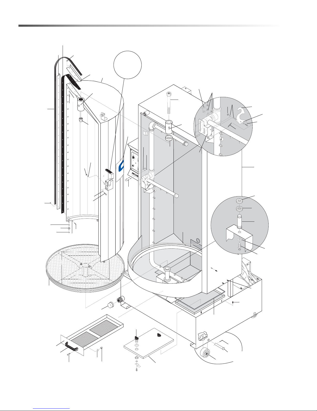
Cuda 2848 Front
1
2
3
4
5
6
7
8
9
10
11
12
13
14
15
16
17
18
19
21
22
23
26
27
28
29
30
31
32
33
34
35
36
37
38
39
41
42
43
44
29
28
27
32
33
34
33
34
35
Field
Installed
25
45
47
47
20
40
24
31
19
For Detail
See Latch
Assy
SH CYCLE
10
A
W
60
20
ER
T
2
HEA
0
2
ST
A
P
N
R
U
50
T
30
S
E
T
U
40
IN
12
M
4
R
6
TE
10
WA
W
ABLE
LO
8
G
TURNT
JO
R
2
0
2
ST
OIL SKIMME
A
P
N
R
TU
12
4
10
6
8
34
CUDA 2848 Operator’s Manual 8.930 -369.0 - AG
Page 35

Cuda 2848 Front
REF PART NO. QTY DESCRIPTION NOTES
1 8.915-208.0 1 ASSY, CABINET 2848
- 8.915-447.0 1 ASSY, CABINET, 2848, W/12" HGT EXT
- 8.921-864.0 1 ASSY, CABINET, 2848, SS
- 8.921-927.0 1 ASSY, CABINET, 2848, W/12" HGT EXT, SS
2 8.915-213.0 1 ASSY, DOOR 2848
- 8.915-452.0 1 ASSY, DOOR, 2848, W/12" EXT
- 8.921-899.0 1 ASSY, DOOR 2848, SS
- 8.921-932.0 1 ASSY, DOOR 2848, W/12" EXT, SS
3 8.915-141.0 1 ASSY, TURNTABLE 2848
- 8.921-910.0 1 ASSY, TURNTABLE, 28 OD, SS
4 8.915-606.0 1 ASSY, DEBRIS TRAY
- 8.921-919.0 1 ASSY, DEBRIS TRAY, SS
5 8.930-275.0 1 COVER, SUMP 10" X 16.5" W/O GAUGE
6 9.804-346.0 1 BEARING, BALL UPPER TT 6206RS
7 9.804-347.0 1 BEARING, BALL LOWER TT 6007RS
8 8.713-234.0 1 SPINDLE, TURNTABLE 2216-2848
- 8.753-685.0 1 SPINDLE, TURNTABLE CHAIN DRIVE, SS
9 8.712-909.0 1 WASHER LOCK 3/4
- 8.749-817.0 1 WASHER 3/4" SPLIT RING, LOCK, SS
10 8.712-855.0 1 BOLT, 3/4",-16 X 1-1/2" GRADE 2 HEX HEAD
- 8.754-309.0 1 SCREW, 3/4" X 1-1/2", HH, CS, SS
11 8.712-875.0 4 PIN COTTER 1/8" X 1-1/4"
12 8.712-939.0 4 PIN CLEVIS 3/4" X 3-1/2"
13 8.713-037.0 4 WHEEL POLYOLEFIN 4" X 2" X 3/4" BORE
14 9.804-378.0 2 LATCH, SUMP COVER
15 8.706-349.0 1 PIPE, CAP, 1-1/2" GALV.
- 8.749-821.0 1 PIPE, CAP, 1-1/2" SS
16 8.712-928.0 1 SPINDLE, DOOR
- 8.753-684.0 1 BOLT, SHOULDER DOOR PIVOT, SS
17 8.930-238.0 1 SPACER, DOOR HUB
- 8.753-836.0 1 SPACER, DOOR HUB, SS
18 8.713-821.0 1 NUT, NYLOC, 5/8"-18 ZINC GR5
19 8.712-852.0 2 GREASE FITTING
20 8.930-242.0 1 ASSY, DOOR LATCH
21 8.915-372.0 1 ANGLE, DOOR SIDE 2848
- 8.915-446.0 1 ANGLE, DOOR SIDE 2848 W/12" EXT
- 8.921-953.0 1 ANGLE, DOOR SIDE 2848, SS
- 8.921-935.0 1 ANGLE, DOOR SIDE 2848 W/12" EXT, SS
22 8.915-200.0 1 ANGLE, DOOR TOP 2840
- 8.921-950.0 1 ANGLE, DOOR TOP 2848, SS
23 8.712-951.0 64" FOAM STRIP 1/8" X 1" ADHESIVE BACK
- - 76" W/12" HGT EXT
35CUDA 2848 Operator’s Manual 8.930 -369.0 - AG
Page 36

Cuda 2848 Front
REF PART NO. QTY DESCRIPTION NOTES
24 8.714-150.0 1 CHAIN W/CONNECTOR LINK
- 8.923.114.0 1 CHAIN W/CONNECTOR LINK, SS
25 9.802-807.0 3 WASHER, 3/8" SAE FLAT
- 8.754-310.0 3 WASHER, 3/8" SAE FLAT, SS
26 8.915-388.0 60" SEAL, BULB TYPE EPDM SIDE PROFILE
27 8.718-794.0 17 SCREW, 10/32" X 3/4", HEX
- - 20 W/12" HGT EXT
- 8.754-306.0 - SCREW, 10/32" X 3/4", HEX
- - 17 WASHER HEAD, SS
- - 20 W/12" HGT EXT
28 9.802-802.0 17 WASHER, 1/4", FLAT, SAE
- - 20 W/12" HGT EXT
- 8.718-965.0 17 WASHER, 1/4", FLAT, SAE, SS
- - 20 W/12" HGT EXT
29 9.804-567.0 17 NUT, 10/32", ESNA
- - 20 W/12" HGT EXT
- 8.754-307.0 17 NUT, 10/32", ESNA, SS
- - 20 W/12" HGT EXT
30 8.713-038.0 6 WHEEL, TRACK
- 8.753-682.0 6 WHEEL, TRACK, SS
31 8.713-266.0 12 E-CLIP, 1/4" MILD STEEL
- 8.753-763.0 12 E-CLIP, 1/4" STAINLESS STEEL
32 8.718-603.0 3 BOLT, 1/4" X 3/4", NC HH SS
33 8.718-965.0 6 WASHER, 1/4", FLAT, SAE, SS
36
CUDA 2848 Operator’s Manual 8.930 -369.0 - AG
Page 37

Cuda 2848 Front
REF PART NO. QTY DES CRIP TION NOTES
34 9.802-774.0 5 NUT, 1/4", ESNA, NC, SS
35 8.718-568.0 4 WASHER, 1/4" FLAT SS SEALING RUBBER
36 9.802-779.0 3 NUT, 3/8", ESNA, NC
- 9.802-780.0 3 NUT, 3/8", STAINLESS, ESNA, NC
37 8.921-304.0 1 LATCH, SPRAY PIPE
- 8.921-955.0 1 LATCH, SPRAY PIPE, SS
38 8.713-020.0 1 SPRING- EXTENSION. 440 DIA. X 2", 6.5 LB/INCH
39 9.804-373.0 1 U-BOLT, 1/4"-20 PLATED
- 8.754-305.0 1 U-BOLT, 1/4"- 3/8" PIPE, SS
40 8.930-307.0 1 STOP, SPRAY PIPE
- 8.921-959.0 1 STOP, SPRAY PIPE, SS
41 8.713-246.0 2 SCREW 5/16"-18 X 1" SOCKET HEAD
- 8.754-316.0 2 SCREW 5/16"X 1", SHCS, SS
42 8.718-980.0 2 WASHER, 5/16", FLAT, SAE
- 9.802-805.0 2 WASHER, 5/16",18-8, FLAT, SAE, SS
43 9.802-776.0 2 NUT, 5/16", ESNA, NC
- 8.754-314.0 2 NUT, 5/16"-18, FLAT, SAE, SS
44 8.915-388.0 48" SEAL, BULB TYPE EPDM SIDE PROFILE
45 9.801-126.0 1 LABEL, CUDA 24 X 6"
46 8.924-172.0 1 BUCKET, OIL NOT SHOWN
47 8.713-265.0 6 CAP, VINYL BLACK, 1/4" X 3/4" LG
48 8.731-254.0 1 PARTS BASKET -SMALL 8 X 8 X 4 NOT SHOWN
49 8.705-957.0 1 CONTAINMENT RING-28 INCH, MARKED RED NOT SHOWN
50 8.915-124.0 1 PARTS TREE, 4 HOOK, 27" X 24" NOT SHOWN
37CUDA 2848 Operator’s Manual 8.930 -369.0 - AG
Page 38
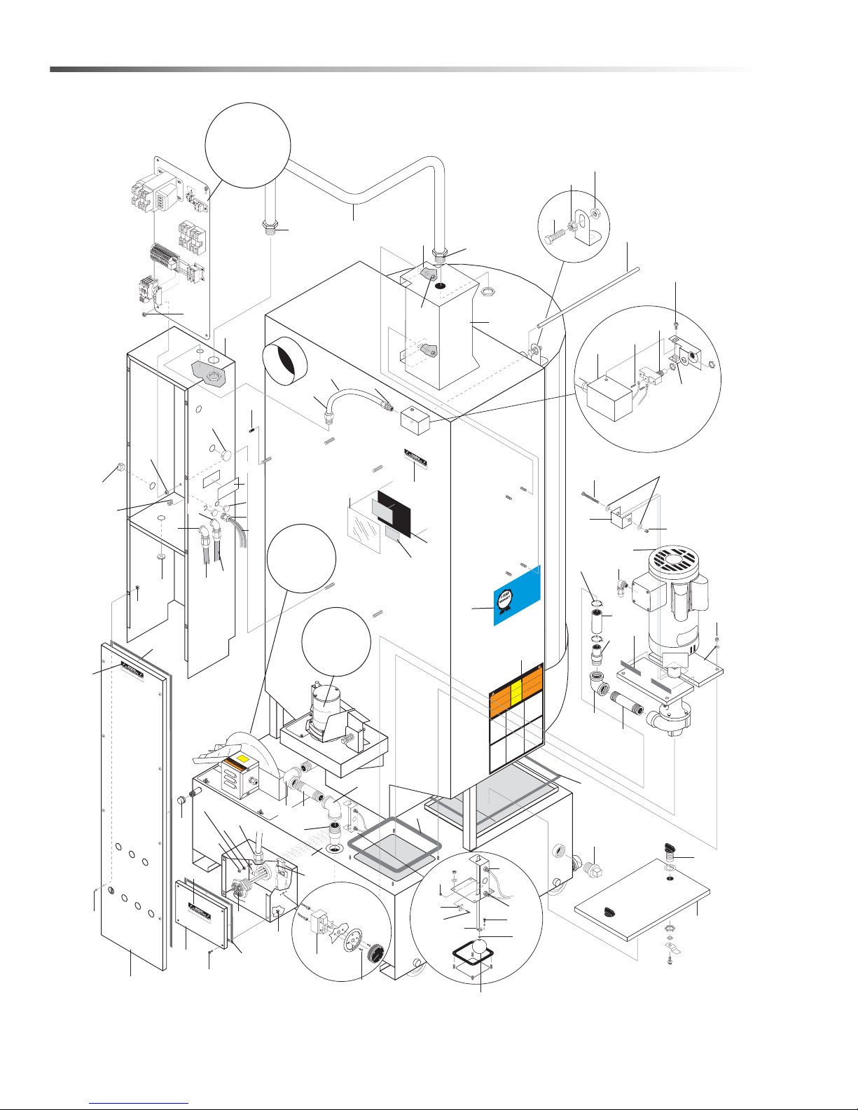
Cuda 2848 Rear
1
2
5
7
8
9
10
12
13
15
16
17
18
19
3
21
22
23
24
25
26
27
28
29
30
47
31
32
33
34
38
39
77
40
41
42
43
44
53
35
45
14
49
15
12
60
14
15
2
56
59
57
54
64
63
62
60
61
49
55
50
46
73
48
5
70
68
69
36
66
65
71
6
67
4
For Details,
See Electrical
Panel
Exploded
Views
37
72
80
3
For
Details See
TT Motor
Page
For
Details See
Oil Skimmer
Assembly
11
5
11
37
60
20
49
74
51
76
52
75
58
GR
O
UND
KEEP
DR
Y
OVED
R
PP
A A
D
TTENTION
YEAR!
O EXTEND
A
T
O 1Y CU
L
R
TE
A
USE ON
W
ARRANTY T
it
DETERGENTS
W
R
ents vis
g
r
LABO
D
E
ONS (15 LITERS) OF
0
T
MIX DETERGENTS 1 LB (1/2 KG) PER
13.
ved Dete
o
Y
r
p
07-5
NT
5-GALL
LIMI
0882
RA
9.8
Ap
.cudausa.com or
A
w
D
R WAR
ABO
E OF
O 1-YEAR
Y L
DS T
S
For CU
IVE US
http://ww
call 888-319-
90-DA
EXTEN
CLUS
ERGENT
DET
A
WITH EX
CUD
T
ed
EN
z
si
EM
y
l
S
r
e
S
ING
p
TI
ro
R
r
E
o
f
V
.
ARN
e
e
D
to a p
l
d
b
A
o
W
/
N
O
nected
I
NEC c
accepta
.
C
on
el
U
c
v
A
.
e
t
y with
C
c
l
wires
p
de l
e
ne
ust be
se
RE
uf
u
m
P
on
h
,
c
c
n
s
ne
or gra
i
i
en
tio
d
ust com
ch
.
e
m
ec
l
un
b
N
C.
n
Ma
EC
floor
-
a
o
s
a
k
e
c
•
da a
l
ati
o N
l
ree
b
y conn
lo
ta
l
g
a
c
tal
dig
c
pp
ó
w grade
UTION
ns
u
o
I
c
l
TTENTIO
0 de
l
s
cone
A
use
e
,
be
•
or
n
.
CA
F
tar
s
ón
ast 9
o
co
use
ci
.
d
r
•
es
R
li
5
ra
at le
ADO /
p
nta
.
g
not
D
ebe
o
I
TE
o
me
um
ntí
is
D
li
c
e
a d
wait
p
guridad
,
y
CU
a
l
c
d
a
i
r
•
s
be
se
WA
l
de
p
de
e
ur
l
s
e
áquin
s
d
e
ng
ado
e
r
nn
o de
op
ni
ón
ow
g
t
o
i
niv
l
e
on
i
l
s
T
l
La m
tric
xi
HOT
90
o
op
N
s
e
ect
de
to a
•
E
n
talac
re
s
os
le t
s
eléc
jo
o
M
n
co
n
f
.
G
i
un
NEC.
ab
E
er de
nds
s
t
-
a
à
eba
me
S
Be
is
n
ing
L
rn
l
d
la
o
té
IS
a
e.
n
tu
nn
.
seco
code
T
util
or
a
•
,
ié
e
ara
,
e
pi
n
R
l
P
p
nec
ar
.
rm/
s
Celsius.
b
au
hi
on
a
opr
c
ur
le
r
on
ice
VE
a
•
és
ma
o p
l
b
ati
p
ie
ARNIN
m
D
d
ti
p
A
sti
am
rmer
a
A
ts
u
tre c
r
o
W
bu
/
U
o
e
nfl
nfér
degr
this
ment
i
ê
E
ll
m
nf
pa
N
i
,
e
N
no
o
G
in
r
n
90
c
’ali
ta
o
co
y
f
s
ai
pa
l
A
r
e
doit
e
e
l
e l
or
ins
D
a
b
i
d
on
s
und
l
e
t
ar
le
UCIO
i
e
n grade
le
ia
p
etc.
po
A
u
create
b
ab
,
par
ent d
Us
do
m
ter
a
s
C
m
l
p
ON
se
.
au mo
os
brir la ta
r
n
co
a
m
will
ma
ou
’
a
o
a
a
i
TI
i
L
e
g
g
RE
dem
fl
spirit
ouil
r
r
le
CALIENT
und
l
P
at
eane
pter
b
o
y
l
l
de
a
nin
i
g
l
ab
•
r
l
n
c
c
RA
a
a
-
a
a
-
verr
se
z
le
ne
É
cce
otator
a
c
warnin
ac
i
ts
c
l
r
r
r
5
se
amm
nst
i
m
d
r
.
so
fl
,
e
Antes
’i
e
pa
with
l
un
a
l
a
i
this
Cette
L
d
e
r
e
eat
t
h
wa
a
,
e
l
is
contaminat
s
b
i
t
or
s
ga
u
s
This
ll
n
a
b
a
fi
m
f
ch
o
ot
u
co
n
n
s
d
e
n
cabi
Do
d
r
ea
de
cl
material
e
haza
insi
b
y
l
g
e
to
d
acin
l
ia
p
xtrem
e
u
mp
q
li
á
an
m
m
un
a
t
co
s
es
e
no
n
le
te
y
e
b
s
a
e
s
Es
le
e
m
t
nt
b
a
r
a
a
fl
me
p
m
le
in
a
s
b
fl
a
a
n
l
i
esta
e
n
flam
e
var
r
n
r
i
material
te
D
e
n
.
s
e
c
al
b
t
o
e
am
a
d
a
id
materi
m
cu
s
re
t
x
i
de
e
p
s
e
d
o
ne
t
t
r
e
n
eu
a
y
s
p
o
tt
de
e
Ne
t
ga
.
n
n
:
s
e
le
m
b
Ce
b
e
tels
a
m
s
o
le
c
seul
b
i
x
t
bin
amm
s
fl
ca
u
n
i
b
s
n
m
du
o
i
r
co
matériau
at
s
tu
i
s
de
es
l’intérieu
à
r d
ée
r
c
TING
A
re
fo
e
OPER
Be
iz
:
r
T
ia
AN
T
Only
amil
.
f
R
s
al
u
vided
IMPO
o
vid
i
ts onto tu
r
d
a
n
completely
p
i
ual pr
a
d
n
g
ff
n
i
cte
ma
d
r
u
is o
r
p
loa
m
e
inst
r
u
o
at ope
p
f
er
t
a
Be
he
t
w
n
th
ai
i
t
k w
n
solutions are
el should
a
t
v
e
ll
l
i
.
mer f
y
r
F
il
.
te
a
1
a
me
k d
W
c
w ti
e
lo
Ch
am heater ti
Al
r
.
g
n
o
o
i
t
d
a
Pr
.
r
an
2
e
d
B
i
l
op
.
/
e
l
or
b
o
m
a
t
solution.
o
d
n
n
tt
r
o
u
Do
b
.
Ope
e
et/t
e
l
.
k
b
3
s
th
m
a
li
t
ba
gh
t
n
r
u
h
u
hro
t
et/t
weig
and la
r
o
“w
t
bask
h
n
r
g
u
, t
hei
h
s
Pump wil
.
a
e
w
m
Close door/lid
.
4
e
.
h
set to
t
aning ti
g
xpired
cle
nin
e
e
seconds f
s
p
w steam
o
ha
o
it 5
ll
a
a
ore
f
l
w
l
i
r to d
Be
w
te
.
a
and
is
5
w
ff
Th
o
.
ss
g
e
n
i
xc
n
e
and
C
AN
N
E
u
d
T
e
N
I
ch
e
s
r
g
y
a
n
i
MA
m
e
low
l
g
o
f
sa
e
u
h
sure elec
r
T
e
h
Onl
g
Be
i
.
:
.
p
H
e
c
m
n
e
ANT
a
T
n
ng su
OR
aini
MP
r
I
d
e
r
ve
o
f
e
l
vice this machin
r
ly
er
e
t
ai
s
:
a
d
Y
w
L
er
k
.
t
c
t
AI
a
n
e
D
w
h
C
me
he
t
le
le
ff
e
•
c
r
o
d
te
n
a
o
f
e
hea
k
v
c
e
ed
e
n
Remo
f
i
n
•
ea
l
Visually ch
c
•
and
h
nal position.
:
door
Y
L
oil
/
e
s
a
e
WEEK
ch
l
:
Gr
a
Y
u
L
s
i
H
•
v
T
m
r
ON
o
f
r
M
e
ash solution fr
P
w
en
b
•
d
ain
i
r
o
v
a
it from bottom of the su
r
• D
to
g
ing the cl
r
en
k
ta
e
r
ment du
he
sump has been cleaned and refilled w
t
add
When
r,
our mac
e
t
ean
r y
a
•
o
cl
w
f
e
t
v
l
man
o
gen
he
ss
i
t
.
D
g
k
:
n
i
an
t
TE
dd
O
a
he
t
N
e
r
o
o
f
t
t
e
b
un
o
am
l
.
o
rra
i
e
i
no
r
g
ant a
e
er
or
ase
e
h
a
n
,
v
m
r
b
,
e
n
i
l
o
m
co
y
ailure
F
.
t
e
c
s
ou
de
r
om
o
c
a
n
i
t
us
b
,
mo
r li
co
e
s
a
te
an
p
s
g
i
l
e
p
s
e
c
s
è
r
u
e
o
y
j
a
y
s
in
l
o
s
les
b
sti
e
u
N
.
t
é
e
u
risq
INST
ating this
r
ope
ourself with i
y
auth
uld
o
h
s
t
o
n
e
nd
t
ing
t
a
and cleaning
be 2" bel
r
o
u
for
a
e
ac
l
t
p
r
e ce
e
b
r
o
t
o
n
for this
t
i
tch securely
ash cy
l st
/
r
doo
or mach
ain f
r
IN
E
as
b
s
i
e
m
l
e
r
i
u
q
ual
q
y
.
e
h
t
n
l i
p
l
il
w
b
e
d
n
a
ge
ug
l
p
r
Reins
.
d
e
s
e
ng
i
f
o
k
c
e
om sump
ing
d
eaning proces
m
om
c
.
e
hin
p
g
n
i
acturer
f
u
p
o
lic
a
a
rv
se
•
u
b
c
le
our
f
i
el
l
e
o
l
,
b
E
f
es
P
gu
a
Uti
s
i
eten
e
ti
t
la
a
gún
pou
b
l
.
d
onn
e
,
on
o
,
a
a
ercle
s
us
r
t
•
s
v
t,
ls
se
b
n
cti
r
ie
u
er
to
le
qu
fi
UD
ONS D’OP
as u
u
en
n
e
ba
r
co
li
a
p
n.
st
A
p
era
e
du p
o
za
n
ca
e
ar
i
’i
r
in
t
le
/du co
n
le o
ie
nn
i
/
N
ette machin
i
d
a
couv
e
i
b
o
m
e
te
p
i
s
t
r
S
t
-
UCTI
t
s
n
mp
CH
cti
a
uel
er c
ond
n
tam
e
a
li
po
.
i
R
n
n
u
na
on
e
-
a
bus
f
r
t
o
q
me
T
o
de
la
U
u
de
i
c
m
utilis
e
l
ne
c
s
e
to
S
om
e
u
o
A
êter
ouvrir le
esenc
aporis
bi
di
te
e
ur
c
r
t
N
c l
r
r
a
n
a
ntes
bl
se
l,
I
a
v
E
e
ant d’
g
secondes pour
r
e
ie
e
o
ture de
v
.
pa
v
é
co
r
n
u
a
h
e
as
A
p
e
llen
sé
o
e
i
o
el
lq
l
v
:
ant d’
s
ag
p
r la ta
ti
u
T
v
lc
r
y
ent
em
u
o
No
ua
a
a
o
A
l’
.
,
e
en
tt
e
c
AN
t
r
s
r
à t
a
sition arrêt et ne
t
e
n
c
ne
le
ê
in
.
RT
ir
les
n
r
il
b
va
e
it
c
i
s d
ol
e
s
A
d
a
attendez 5
u
re
s
r
d
ne
pièces su
d
.
a
a
n
v
e
ou
r
ge sont
o
ada
e
g
IMPO
u
i
r
a
r
tio
d
t
) s
mé
p
on
v
p
u
r
app
o
,
l
tou
a
n
in
CION
l
o
permettre au br
m
s
p
ous complètem
f
ne
t
t
pou
i
e
v
e
x
t
ent des
e
so
A
il
d
(2
e
ce
e
e
s
de
on
r
i
é
em
a
un
le
s
ur/plaque tournante d’arr
’
i
mach
.
m
s
cm
ns
t
r
d
la pompe est en po
te
a
tib
t
.
5
to
app
d
cauc
e
e
à
nant
u
matériau
.
l’
e
us
g
e
r
a
r
o
u
r
l
e
b
a
oir du temps
s
er
emen
as
ese co
nt
y
v
v
ce
n
d
ea
m
s
o
’
So
u
a
es solutions de
de
é
o
tt
.
co
t
en
urer que
v
ou du charg
.
r
r
i
ro
co
pl
c
Pré
e
e
t
r d
iaríc
a
age
a
.
t
l
y
Utilise
f
r
s
f
es
n
n
oi
tid
e
e
u
ve
a
.
v
peu
u
o
s
a
le
r
e
p
é
a
èc
de
amil
s’ass
no
t
i
f
s
r
e
i
à
ncl
ff
emen
t
qu
o
s
n
,
p
o
n’y est
n
s d
u
de
n
r
ch
o
d
ba
io
s
a
il
e
t
e
t
p
za
fi
pas et que l
m
ebe
h
eau,
ion
le
i
u-del
’
lu
me
d
t
e
au
r
c
les à être
an
r
d
o
c
e
e
d
r le ré
e
a
bo
i
v
pi
e
s
t
s
r
tic
d
Vé
a
d’
a
do
d
r
l equi
s
on
e
n
.
i
f
se
l
la
a
a
es
b
à
te
u
a
,
e
ou
pa
.
s
e
z
i
r
o
p
o
a
nt
r
n
u
r
p
m
o
s
e
d
t t
ni
ticl
r
n
ain
n
o
y
xceed the specifi
e
e
cl
r
a
t
lid,
to esca
rom
ST
d
e
e
r
o
ical supp
r
t
ifie
su
ent d
v
e
r
ris screen
d
.
n
r
u
t
m
d
r
o
ded
n
e
wder into
o
.
ous qu’
s
u
s
o
t
e
ut
V
a
contamine
e
i
f
rtis
la
e
v
r
a
è
e
.
n
r
le
c
f
u
e
o
i
a
c
f
e
r
a
b
q
l
Rempli
v
ación que se i
a
ve
u
a
ou
i
ez-
r
UCCIONESDE OPER
a
.
limpieza
a
t
it
etc
ac
z les
r
s
’
r
e
r
r
sh
ap
1
,
n
e
u
ha
de
l
m
s
d
p
R
a
c
c
opa
c
e
o
o
e
ss
Le
m
a
dan
c
o
“w
nctionnement souhaité
te
s
a
es
e
t
r
o
r
A
r
u
e
lc
f
.
r
fla
pré
r
e
d
u
e
o
l
e
o
n
El
t
e
v
in
.
ta/cubie
p
t
r
t et pl
ammer le mi
de
r
er
a
c
ua
r
amen
r
u
INST
egú
e
e
açon sécu
z
n
ion
a
n
e
g
n
e
s
f
t
nan
u
pareil
Antes de
e
v
o
r
i
a
ai
c
e
bs
bid
p
p
od
p
u
,
d
mi
e
o
p
Pr
a
’a
ri
a
on
l
e
d
m
e
f
t
.
a
l
i
é
s
to
as soluciones de
t
l
r l
s
2
el ma
i
r
t l
p
ez de
e
z
y
a
r
te/cou
ll
a
e
ue
p
ANTE:
o
r
r
n
a
.
que
l
e
an
u
T
ne
o.
d
o
a
e
a
t
r
s
d
r
t
p
ie du
a
R
p
laq
p
om
s
u
/c
r
n
z
s
o
p
i
a
e
a
a
n
r
a
erroui
d
, y que l
r/
s
l
pou
ó
na
o
v
ut
o
r l
e
r
t
ép
e
ulé.
i
ar
La p
t
n
e
ci
e, to
dad
r
rí
amien
u
u
i
IMPO
.
n
e
d
m
u
d
de
v
e
n
o
l
a
n
é
o
t
ag
p
r
t
u
o
r
pani
i
io
ce
v
j
na
ci
Antes de ab
e
Ou
s
r
e
.
so
a
è
a
n
os
el
l
i
la
.
v
o
nc
pletamente con
a
b
v
le
l
onal
qu
secondes que
3
dé
p
u
a
r
p
apeur
fu
i
r
s
e
f
u
v
r
ue
de
n
y
r le
a
s
e
pla
ne
r
a
/
p
q
la
.
pe
r
o
equ
age
d
r
a
te/cou
cu
y si
-
e
e
r
v
p
r
gu
a
, mettre la mi
à
onné soit éco
t
o
r
r
RUCTIONS
a
,
e
"
l
l
a
a
au
u
to
ste
e
r
ain
c
ad
2
t
é
at
ada
on
a po
pendant 5
p
la
r
n
er
’écouler d
g
ar
e
t
v
amen
e
e
c
n
i
l
r
n
s
prête pou
mett
s
u
du
r
p
-
r
a
to
e
e
a
i
carga sobre la to
i
apa
r
s
mez l
ctio
l c
end
em
machin
a
so
r
ly
t
d
ó
u
.
l
be
r
v
t
xceda
e
e
r
e
de
e
sté
e
a
e
e
za
l
F
a
v
d
e
d
i
te/le co
.
dep
ie
n
e
nst
r
or
n
t
a
4
d’eau de
a
l
za.
Cela pe
rop
-
.
l
p
s
e
r
u
No
e
êt et at
.
ie
au temps de la
sté
e
p
n
”
La machine
zad
p
e
na
pasar un tiempo pa
i
ner
ag
e
e
sa
l
r
xcè
ne
r
la po
nd
’arr
m
u
i
o
e
u
gu
l
el
a
gabi
rir
h
Lle
fiq
cyc
l
a
i
a
s
l d
r
.
r
nin
uv
e
à l’
ed
Deje
n
a
et, be ce
e
.
name
a
1
emp
i
e
r
k
a
v
o
T
.
w
u
i
V
r
age à l
p
ate this machin
ue
l
d
e
r
q
n
v
a
jusqu’à ce que temps sélecti
n
e
e
a
n
a
e
á
q
s
o.
ó
l
que las piezas
bas
p
i
n
la to
e
u
s
ant d’o
th
/
m
l
se
c
a
e
e
de
v
r
e
e
p
m
e
u
y
l
e
ce
á
d
A
d
la
nd
e
o
s’arrête de to
b
ol
d
n
d
ra
e
.
a
n
e
g
5
es
s
ro
o
g
t
r
ón
.
a
i
.
ú
s
C
l
c
e
Pro
.
e
nin
a
r
.
“ci
t
.
íme
o
r
eg
u
n
2
s
e
t
e
er
e
a
p
a
ta/tapa y colo
i
p
r
l
r
,
o
r d
y f
l
e
a
e
a
o
c
u
rá
st
p
solution
ad
a
ni e
ca
pre
z
n
i
o
la
r
a
an
a
o
r
/c
r
r
ond
a
f
sa
Ab
l
ng
w the access door
e
a
.
i
b
e
3
e
s
iod of
ean
om
nam
r
a
la
e
b
cl
t
tes especificados de peso y altu
p
La
ue
d
e
brep
to
.
.
mi
e
d
i
hea
q
o
, ajuste el temp
o
ir
r
e
ta/tapa y asegure el candad
a
d
r
r
a
ga
l
v
a
e
o.
los l
ea
nad
a
a
d
l
o pr
s
pu
ean on
ta, apague el tempor
a
s p
e
e
r
r s
d
e
o
cl
av
i
do
l
ud
o
b
r
n
ap
t
p
u
be
v
e
g
m
/cu
l
h
.
t
e
e
pro
a
e
i
s
t
f
s
Cierre la
t
r
a
e
l
.
es to
ts
z
e
r
4
s o
a
e
u
a
.
qu
empo seleccio
”
ed
t
p
p
en posición de
e
á
de
pi
a
o
n
pere 5
ado
si
itir
s
r l
v
i
e
IM
e
r
m
a
h
l
r
cabi
t
y
ante el ti
d
r
o
sh
u
d
o pe
a
d
a
ene de las
TEN
v
st
w
achine
a
l
y
E
.
a
a
a dr
r
r
u
a
AN
th m
e
n
r
Antes de ab
i
i
.
sp
t
g
5
f
Wi
n
im
M
t
.
o
e
l
i
c
ciclo de
ás
d
t
E
a
n
m
e
n
D
u
o
ta
e
s
dej
n
u
un
u
timer to the desired
e
xceso de agu
S
r
”
s
ec
e
n
r
e
d
f
l
r
r
U
t
n
e
s
.
p
c
a
o
á
e
t
p
i
s
m
elé
ONE
u
spin
I
e
o
q
t
u
e
ash cycle timer
q
C
en
i
ema
el
w
o
t
d
m
i
n
n
r
o
n
e
i
UC
i
sist
u
e
t
el
m
ed
i
n
ine to stop
.
the cabinet
n
a
m
s
TR
e
t
o
t
m
r
pe
Sólo personal c
r
que
.
n
r
p
n
a
u
te
o
de
m
r
r
s
i
INS
r
u
e
riamen
our pa
se
d
a
n
y
ue
u
re
n
q
di
ú
a
e
n
l
r
g
e
ter
p
e
e
l
r
o
S
d
E
aciar el cá
d
e
As
v
cá
a.
a
N
u
:
l
vitará dañar el
s
e
e
E
a
uin
o p
b
n
a
q
r
e
e
v
gu
ANT
má
e
a
T
ua
s
l
a
R
.
g
e
st
a
UCTIO
de
s
e
u
el
R
r
.
a
a
e
d
IMPO
r
ado
e-
g
GADO antes de
ib
t
:
a
el
r
Re
a
n
A
.
v
r
cu
i
c
i
as están instaladas
P
o
l
e
a
e
i
l
n
rep
a
r
v
A
d
.
m
l
r
a
a
a
el
t
o
n
n
e
d
el
ebe
o
a
v
d
i
AMENTE
ue
q
ueb
l n
ent
r
e
d
l
r
duos de
e
a
es neces
f
c
er
DIARI
l
houl
n
e
Comp
e
s
d
ly is OFF be
el
o
t
ant
n
mpie si
•
n
M
en
o
m
mpie los resi
rs
e
p
ele
d
.
xacta.
Retire y li
.
e
ta
e
r
l
uebe visualmente que las boqui
e
ng
Retire y li
i
r
u
na
p
p
gi
•
op
ri
he
la
T
o
t
.
Comp
o
y
l
de
t
a cadena de propul
ón
i
e
ai
e del
:
c
g
•
i
as
E
r
correctament
s
p d
T
g
no
retir
N
m
po
,
ama
e
r
E
a
d
l
M
te
r
o
L
A
ad
cá
N
l
e
:
e
v
i
uid
E
d
o
.
ique las bisa
T
ig
c
r
m
r
N
ificación visual de l
ante el proceso de
za
b
SEMA
o
r
er
r
E
e
t
n
e
u
Lu
Re
c
M
v
e
.
d
ag
a
L
s
t
.
mpi
x
e
i
e
e
A
na
l
e
d
l
•
b
U
u
dor
e
zz
S
o
e
ta
de
N
c
D
.
no
en
n
E
l
en
s
l
namesa
ali
M
r
o
e
t
ció
rel
to
ca
u
R
l
l
tall in the
y
a
e
io
d
so
•
a
s
de l
l
e
t
nto
limp
n
e
ne
a
e
m
c
stá
e
le
ri
Dr
e
nt
b
e
ter los sedimen
e
l
a
i
f
er
r
.
t
l
al
r
•
n
e
i
e
cá
c
a
r
cá
recomendada de detergente pa
a
.
h
o
ñar
u
c
p
el
a
g
za
e
d
a
e
a
ie
v
d
i
u
n
r
a
q
e
d
d
e sand/
imp
z
e
l
e
v
t
l
e
en
-
o
n
b
v
d be
e
m
e
a
l
t
a
o
g
r
n
e
e
ec
t
U
, rem
er
r
t
e
.
d
d
regue la cantidad
a
a
l
g
•
n
d
e
hea
i
a
t
ui
a
g
n
v
Care shoul
l
.
a
áq
in
ith
p
e
c
g
m
u
a
a
l
s
i
-
r
m
.
n
D
a
s
e
te
e
e
A:
d
u
T
f
q
O
o
N
an
t
ty
l
i
t
a
n
r
o
a
l
te
a
qu
w
m
r
a
w
s recommended
’
i
o
m
nar
t
ycl
t
o
cl
e
i
c
r
c
ion
t
t
rrê
a
un
en
’
sa
l
i
l
l’appareil
n
ti
à
-
u
r u
st
é
.
e
r
e
s
s’échapper du cabinet et
n
ge
t
e
i
e
u
x
e
doi
izador del
qu
ur
t
pièc
na
ri
é
y
i
s
fi
u
i
e
t
peu
dé
áq
n
élect
e
ne
t
i
o
qual
m
f
b
l
an
a
t
st
g
r
e
l
DIRECTIVES D’ENTRETIEN
nne
t
po
n
-
a
système
m
rso
s
i
v
e
i
é
s
r
r
p
u
l
e
e
te
l
i
p
s l
n
que le
év
n
eau su
o
eul
l
i
a
d’
b
S
d
t
at
.
ta
e
r
s
O
i
au
o
m
tili
T
r
v
assurer
Le
u
r
d’e
N
pe
t.
S’
:
ne
E
u
I
U
eau
uen
NT
v
’ea
-
i
q
A
d
er
n
T
.
ré
á
f
t
le
R
s
en
i
:
t
e
d
T
i
,
o
t
N
n
fant.
.
ó
te
de vider le rése
i
s
IMPO
n
c
quo
ri
appareil
Réinstall
auf
e
.
nemen
b
ant
u
et
n
v
c
e
a
e
t ch
age
r
n
idi
sont bouchées/ob
.
pliss
parer c
te
éme
quot
l
s échéant
TIDIENNEME
ses
r
é
sté
em
’
u
O
e
e
r
b
.
fi
U
r l
i
e
r
le ca
er le filtre à dé
Q
t
Le
co
i
r
y
,
r
cado
.
age
o
Vé
r
e
tt
t
y
m
oi
alifi
o
v
.
t
ne
r
•
t
e
t
e
t
e
c
e
n
emen
ndom
t
er
xa
’e
e
în
t
e
d
a
r
r
e
t
on
le
uellement si des
nières de la po
s
ia
r
en
ont
ém
.
nit
D
m
i
e
t
/cha
:
n
ver tout
ifier vi
Dé
T
r
e
ent
•
.
l
tio
v
N
i
s
s
Vé
e
po
ué
entures
ant
r
f
t
•
f
a
, et en
l
r
s
.
ons doi
e
s
oi
AIREME
n
v
hau
el de la chaîne d’
r
ag
a
D
y
d
se
o
nt c
a
l
ré
:
r
T
u
e
r/huiler les p
t
éme
d
l
u
é
o
’
ntrôle visu
j
l
.
EBDOMA
Des précauti
l
s de nett
i
a
.
age
aisse
H
e
,
e
v
r
t
nd.
tale en
u
a
Gr
a
l
n
o
a
f
p
urber
e
ins
’
p
o
na
u
d
a
r
c
•
a
i
/
t
l
t
e
processu
r
p
t
ier
an
tou
l
an
o
m
v
e
ution de
v
v
l
e
a
p
r
MENSUELLEMEN
b
océder à un co
r
e
t
u
e
de
Pr
urs du
o
r d
trou
u
p
é
te
y
i
e
o
•
v
é
t
de la ta
t
é
cha
d
ier se
e
u
n
v
n
a
a
ea
r
é
t
l’
pour
g
/
é
Assécher la sol
s
mm
s
0
le
a
n
.
o
b
c
r
2
mmager au co
se
i
i
a
•
e
0
da
sión
r
o
r
s
4
v
p
e
r
t
r
e
n
d
22-
s
e
é
être
g
.9
r
e l’endo
r
pou
8
e
e
e
t
l
d
a
é
l
e
d
ou d
o
u
d
re
e
q
.
d
r
d
s
r
on
oi
f
é
r o
o
t
v
i
a
L
sou
r
t
l
n
b
se
a
dis
o
é
u
•
r
d
q
en
e
Bi
s l
:
n
E
T
da
O
er
N
t
u
o
j
,
a
’
a
a
l
d
u
a
r
-
r
a
g
e
r
g
a
e
d
.
e
t
n
a
GR
OUN
D
38
CUDA 2848 Operator’s Manual 8.930 -369.0 - AG
Page 39

Cuda 2848 Rear
REF PART NO. QTY DESCRIPTION NOTES
1 8.916-077.0 1 CONTROL ARM CONDUIT 2848
2 8.712-972.0 2 HUB, CONDUIT 1-1/2" NPT, THRD
3 8.706-193.0 2 ELBOW, 90° 1-1/2", GALV.
- 8.706-192.0 2 ELBOW, 90° 1-1/2", 304, SS
4 8.730-382.0 1 NIPPLE, 1-1/2" SCH40 X 5-1/2"L
- 9.804-418.0 1 NIPPLE, 1-1/2" SCH40X 5-1/2" L, SS
5 9.802-778.0 12 NUT, WHIZ LOC 5/16" FLANGE
6 8.713-265.0 1 CAP-VINYL BLACK
7 8.915-256.0 1 ASSY, ELECTRICAL BOX
8 8.930-252.0 1 COVER, ELECTRICAL BOX
9 8.921-961.0 1 COVER, HEATING ELEMENT, SS
10 8.749-191.0 1 HEATING ELEMENT, 9KW/208V/1PH/3PH
- 8.712-954.0 1 HEATING ELEMENT, 9KW/230V/1PH/3PH
- 8.713-179.0 1 HEATING ELEMENT, 9KW/460V/3PH (1.043-424.0)
- 8.713-178.0 1 HEATING ELEMENT, 9KW/575V/3PH (1.043-425.0)
11 9.804-094.0 124" WEATHERSTRIP 1/8 X 1/2
12 8.713-593.0 1 THERMOSTAT, SNAP DISC 180°F, 1 PHASE
- 8.713-030.0 1 THERMOSTAT, BLB & CPLLRY 195°F, 3 PHASE
13 8.706-350.0 1 PIPE, CAP, 1/2", GALV.
- 8.753-615.0 1 PIPE, CAP, 1/2", SS
14 8.718-794.0 12 SCREW, 10/32" X 3/4", HEX
- 8.754-306.0 12 SCREW, 10/32" X 3/4", HEX SS
15 9.802-791.0 14 NUT, CAGE, 10/32" X 16 GA
16 9.804-510.0 1 SWITCH LID/DOOR 15 AMP, NON-ENCLOSED
17 8.930-265.0 1 BOX, ELECTRICAL DOOR SWITCH
18 8.716-377.0 2 TERMINAL, RING TONGUE, 14 AB-10
19 8.735-007.0 1 ROD, DOOR SWITCH 5/16" X 19.5" ACRYLIC
20 9.802-525.0 1 LOCKNUT 1/2"
21 8.706-343.0 1 PIPE, BARBED/MALE NPT 1-1/2" GALV .
- 8.753-963.0 1 PIPE, BARBED/MALE NPT 1-1/2" STAINLESS
22 9.804-399.0 1 GROMMET, PIPE VINYL 1-1/2"
23 9.804-375.0 1 GASKET, PUMP PLATE
24 9.804-376.0 2 GASKET, PUMP PLATE CENTER SELF ADHESIVE
25 8.709-081.0 2 CLAMP, SCREW, #28 P/N 6828
26 8.749-190.0 8.5" HOSE -1 1/2" AG 200
27 8.713-135.0 1 PIPE, BARBED/MALE NPT 1-1/2"
- 8.753-963.0 1 PIPE, BARBED/MALE NPT 1-1/2" STAINLESS
28 8.706-195.0 1 ELBOW, 90° 1-1/2" FEMALE, BLACK
- 8.706-192.0 1 ELBOW, 90° 1-1/2" FEMALE, SS
29 8.735-005.0 1 NIPPLE, 1-1/2" X 2.5" LG SCH 40
- 8.753-616.0 1 NIPPLE, 1-1/2" X 2.5" LG SCH 40 SS
(1.043-423.0,
1.043-421.0)
(1.043-422.0,
1.043-394.0)
39CUDA 2848 Operator’s Manual 8.930 -369.0 - AG
Page 40

Cuda 2848 Rear
REF PART NO. QTY DESCRIPTION NOTES
30 8.715-421.0 1 PUMP, SCOTT 5HP 230V 1 PH (1.043-422.0)
- 8.715-422.0 1 PUMP, 5HP 208/230/460V 3 PH
- 8.715-424.0 1 PUMP, 5HP 575V 3 PH (1.043-425.0)
- 8.749-192.0 1 PUMP, SCOTT 5HP 208V 1 PH (1.043-421.0)
31 9.802-779.0 4 NUT, 3/8", ESNA, NC
32 9.802-807.0 4 WASHER, 3/8" SAE FLAT
33 9.804-378.0 2 LATCH, SUMP COVER
34 8.921-957.0 1 ASSY, SUMP COVER 10" X 16.5", SS
35 8.712-132.0 1 FLOAT, 3 1/2" BLL, STEEL SS
36 8.930-271.0 1 ASSY, CONTROL BOX
37 9.802-781.0 2 NUT, 3/8" FLG WHIZ LOC
- 8.754-311.0 2 NUT, 3/8" NC, WHIZ LOC FLANGE, SS
38 8.706-327.0 1 PLUG, 1.5", PIPE, GALV.
- 8.706-251.0 1 PLUG, 1.5", PIPE, SS
39 8.922-155.0 1 FLOAT, ROD, SS
40 8.718-806.0 1 SCREW, 1/4-20 X 1/2" SHCS STAINLESS, SS
41 9.804-119.0 1 SWITCH, MAG. REED SENSOR, NC
42 9.804-118.0 1 SWITCH, MAG. REED SENSOR, NO
43 9.804-120.0 1 MAGNET, REED SENSOR TARGET
44 8.718-847.0 1 NUT, 4-40 KEPS, ZINC
45 8.731-134.0 1 SCREW, 4-40 X 1/2" SLOTTED P/H M/S ZINC
46 8.922-402.0 1 LABEL, WARNING, INSTRUCTIONS CUDA APW
47 9.807-513.0 1 LABEL, CUDA APPROVED DETERGENTS
48 9.800-034.0 1 LABEL, CLEAR LEXAN
49 9.800-016.0 3 LABEL, DISCO POWER SUPPLY
50 9.803-831.0 2 CONNECTOR, 3/4" L/T, 90° BLACK
(1.043-423.0, 1.043-394.0,
1.043-424.0)
40
CUDA 2848 Operator’s Manual 8.930 -369.0 - AG
Page 41

Cuda 2848 Rear
REF PART NO. QTY DES CRIP TION NOTES
51 8.719-030.0 1 WASHER 3/8" STAR
52 8.718-960.0 2 WASHER FLAT 3/16 ZINC
53 8.915-388.0 48" SEAL, BULB TYPE EPDM SIDE PROFILE
54 9.804-297.0 1 LABEL, HOUR METER
55 8.706-755.0 1 BUSHING, .875"
56 8.706-744.0 1 PLUG, PLASTIC 1"
57 9.802-105.0 2 PLUG, 7/8", HOLE
58 9.802-517.0 1 CONNECTOR, 1/2" L/T, 90° BLACK
59 9.802-515.0 1 STRAIN RELIEF, STRT, LQ TITE 3200
60 8.716-547.0 3 CONNECTOR, 1/2" L/T, STR, BLK
61 9.802-448.0 22" CONDUIT, SEALTITE 1/2"
62 9.803-832.0 35" CONDUIT, WATER TIGHT, FLEX 3/4"
63 9.802-448.0 32" CONDUIT, SEALTITE 1/2"
64 9.802-423.0 66" CORD, SERVICE, SEO, 16/3
65 8.718-980.0 4 WASHER, 5/16" FLAT
66 9.802-776.0 4 NUT, 5/16" ESNA NC
67 8.725-300.0 1 PLUG, PLASTIC 1.125"
68 8.718-611.0 1 BOLT, 1/4-20" X 3-1/2" NC HH TAP
69 8.913-741.0 1 SPACER, PUMP
70 9.804-361.0 1 LABEL, PATENT NUMBER
71 9.802-773.0 1 NUT, 1/4" ESNA NC
72 9.802-772.0 1 BOLT, 3/8" X 1-1/4" LG
- 8.754-312.0 1 SCREW 3/8" X 1-1/4" HH, CS, SS
73 9.800-013.0 1 LABEL, ASSEMBLED USA
74 9.800-040.0 1 LABEL, GROUND SYMBOL
75 8.718-810.0 2 SCREW 10/32" X 1/2" WHIZ LOC
76 9.803-249.0 2 SCREW M 4 X 10 (3 PH ONLY)
77 8.718-978.0 1 WASHER, 1/4", SPLIT-RING LOCK, SS
41CUDA 2848 Operator’s Manual 8.930 -369.0 - AG
Page 42
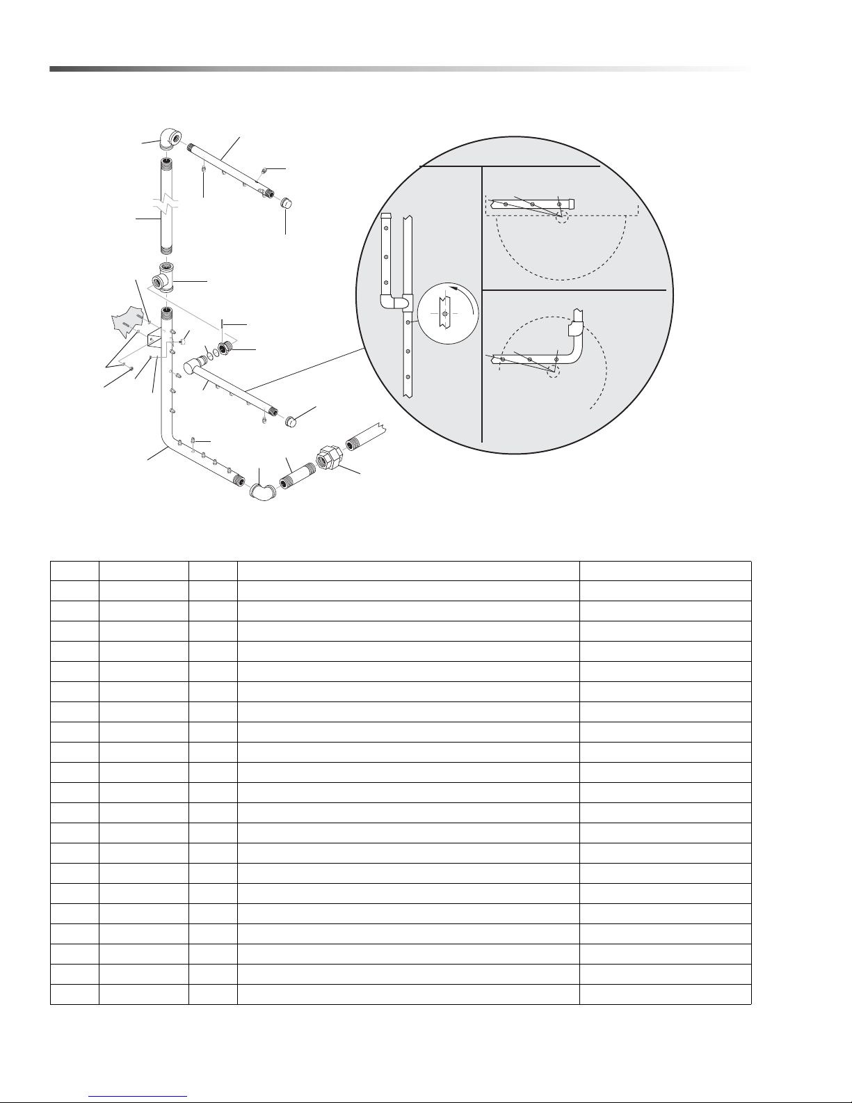
Spray Arm
7
8
10
10
9
6
5
14
13
16
12
11
9
10
1
2
3
4
18
17
15
Rotate Each
Nozzle
Approx.
3° From
Center Line
Of Pipe
Align Notch In
Each Spray Nozzle
With The Center
Of The Turntable
SIDE
VIEW
TOP
VIEW
19
19
REF PART NO. QTY DESCRIPTION NOTES
1 8.713-136.0 1 UNION, 1-1/2", BLACK
- 8.706-332.0 1 UNION, 1-1/2", SS
2 8.735-006.0 1 NIPPLE, 1-1/2" X 6.75" LG SCH 40
- 8.921-946.0 1 NIPPLE, 1-1/2" X 6.75" LG SCH 40, SS
3 8.706-195.0 1 ELBOW, 90° 1-1/2", BLACK
- 8.706-192.0 1 ELBOW, 90° 1-1/2", SS
4 8.915-367.0 1 LOWER ASSY, SPRAY MANIFOLD 2848
- 8.915-442.0 1 ASSY, LOWER MANIFOLD 2848 W/12" EXT
- 8.921-936.0 1 LOWER ASSY, SPRAY MANIFOLD 2848, SS
- 8.921-940.0 1 ASSY, LOWER MANIFOLD 2848 W/12" EXT, SS
5 8.706-219.0 1 TEE, 1-1/2", FEMALE, PIPE BLACK
- 8.706-220.0 1 TEE, 1-1/2", FEMALE, PIPE, SS
6 8.915-369.0 1 NIPPLE, 1-1/2" X 23" LG SCH 40
- 8.915-445.0 1 PIPE, UPPER 2848 W/12" EXT
- 8.923-968.0 1 NIPPLE, 1-1/2" X 22-1/4"" LG SCH 40, SS
- 8.921-954.0 1 PIPE, UPPER 2848 W/12" EXT, SS
CUDA 2848 Operator’s Manual 8.930 -369.0 - AG
7 8.712-996.0 1 ELBOW, 90° 1-1/2" X 1" REDUCING BLACK
- 8.706-192.0 1 ELBOW, 90° 1-1/2", SS
- 8.753-737.0 1 BUSHING, 1-1/2" X 1" NPT, SS NOT SHOWN
8 8.915-370.0 1 PIPE, UPPER SPRAY MANIFOLD
- 8.921-952.0 1 PIPE, UPPER SPRAY MANIFOLD, SS
42
Page 43

Spray Arm
REF PART NO. QTY DESCRIPTION NOTES
9 8.706-081.0 2 CAP, PIPE 1 NPT 150WP NON PL
- 8.753-614.0 2 CAP, 1" THREADED, SCH 40, SS
10 8.712-973.0 20 NOZZLE, 50° #6
- 8.749-193.0 24 NOZZLE, 50° #5 W/12" EXT
- 8.749-638.0 20 NOZZLE, 50° #6, SS
- 8.754-086.0 24 NOZZLE, 50° #6 W/12" EXT, SS
11 8.915-217.0 1 ASSY, SWING ARM, SPRAY ARM
- 8.915-444.0 1 ASSY, SWING DOWN SPRAY ARM 2848 W/12" EXT
- 8.921-942.0 1 ASSY, SWING ARM SPRAY ARM, SS
- 8.921-944.0 1 ASSY, SWING DOWN SPRAY ARM 2848 W/12" EXT
12 8.713-239.0 1 SWIVEL, BUSHING HEX
- 9.804-435.0 1 SWIVEL, BUSHING HEX, SS
13 9.804-367.0 2 O-RING, SWIVEL #125 BUNA 1.299" ID X 1.505" OD
14 8.724-360.0 1 PIN, ROLL 3/16" X 1-5/8"
- 8.754-308.0 1 SPRING PIN, 3/16" X 1-5/8" SLOTTED, SS
15 9.802-779.0 2 NUT, 3/8", ESNA, NC
- 9.802-780.0 2 NUT, 3/8", STAINLESS, ESNA, NC
16 8.713-187.0 1 RUBBER BUMPER, 1/4" STEM
17 9.802-773.0 1 NUT, 1/4", ESNA, NC
- 8.754-303.0 1 NUT, HEX, 1/4"-20, ESNA, SS
18 8.718-965.0 1 WASHER, 1/4", FLAT, SAE, SS
19 9.802-807.0 4 WASHER, 3/8" SAE FLAT
- 8.754-310.0 4 WASHER, 3/8" 18-8, FLAT, SS
43CUDA 2848 Operator’s Manual 8.930 -369.0 - AG
Page 44
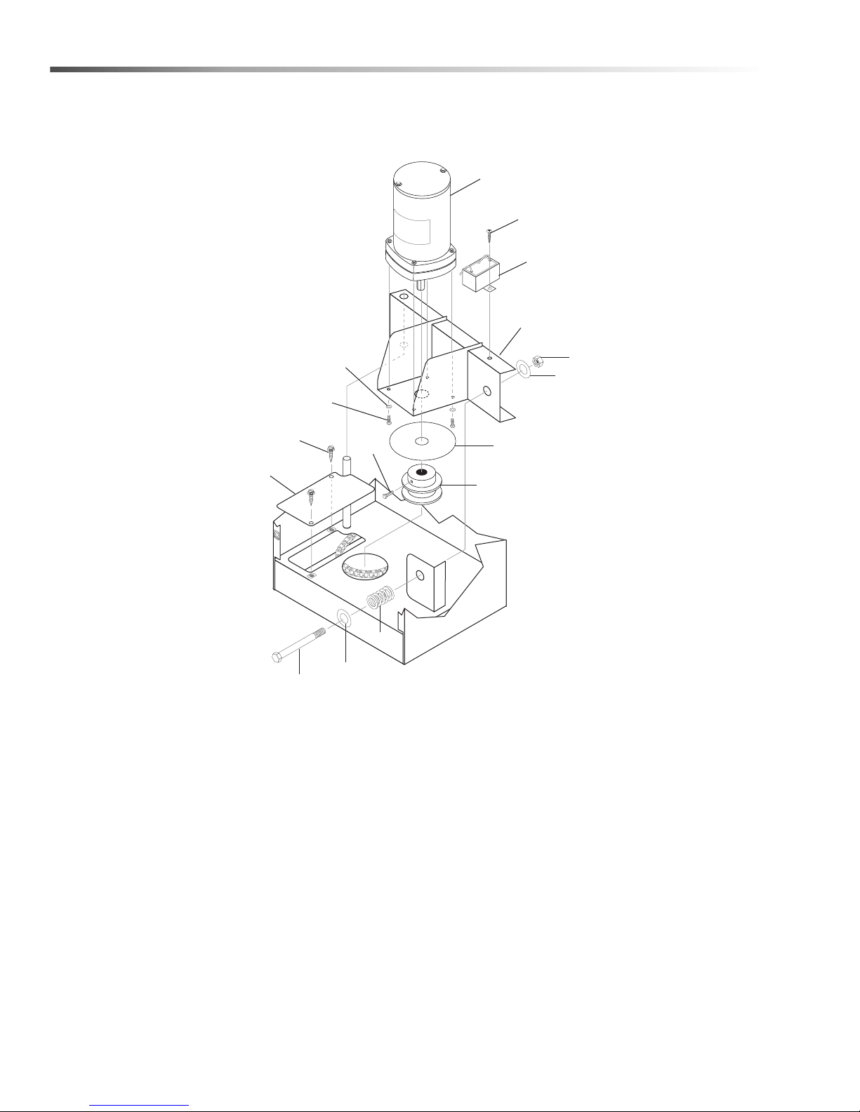
TT Motor
1
15
4
10
11
7
8
5
6
2
3
9
13
11
12
14
44
CUDA 2848 Operator’s Manual 8.930 -369.0 - AG
Page 45

TT Motor
REF PART NO. QTY DESCRIPTION NOTES
1 8.725-371.0 1 GEAR MOTOR APW
2 9.802-798.0 2 SCREW, #10 X 1/2", TEK HEX HEAD
3 8.921-956.0 1 COVER, GEAR MOTOR BOX CHAIN ACCESS SS
4 8.930-268.0 1 ASSY , GEAR MOTOR SWING ARM
5 8.713-036.0 4 WASHER -RUBBER BONDED #10
6 9.802-698.0 4 SCREW, 10/32" X 1/2" BH SOCSS
7 8.752-174.0 1 WASHER, GEAR MOTOR, STAINLESS
8 8.714-008.0 1 TORQUE LIMITER -STD SIZE
- 8.754-199.0 1 TORQUE LIMITER -STD SIZE, SS
9 9.804-511.0 1 SCREW SET 1/4" X 28 X 3/8 SS
10 9.802-779.0 1 NUT, 3/8", ESNA, NC
11 9.802-817.0 2 WASHER, 1" STEEL
12 9.804-423.0 1 SPRING, .875 OD X 2.50 LG X .120- 74 LB/IN
13 8.718-685.0 1 BOLT, 3/8", 16 X 5" HEX HD. PLATED
14 8.725-437.0 1 CAPACITOR
15 8.718-937.0 1 SCREW #8 X 3/4" PHILLIPS ZINC PLATED
45CUDA 2848 Operator’s Manual 8.930 -369.0 - AG
Page 46
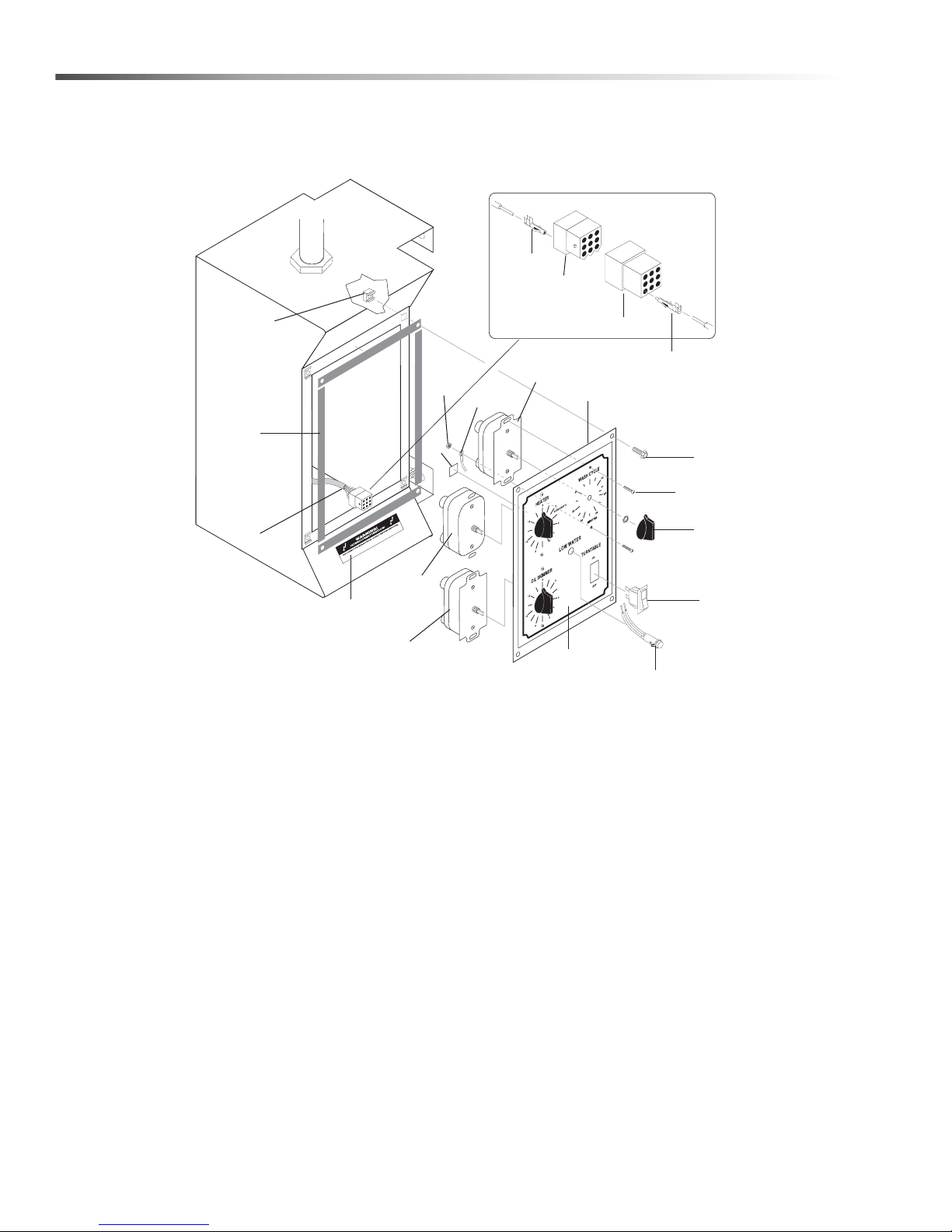
Side Control Panel
17
1
19
18
5
6
15
21
16
4
2
3
8
7
9
10
14
11
12
13
20
46
CUDA 2848 Operator’s Manual 8.930 -369.0 - AG
Page 47

Side Control Panel
REF PART NO. QTY DESCRIPTION NOTES
1 9.804-094.0 30" FOAM STRIP 1/8" X 1/2" ADHESIVE BACK
2 8.930-240.0 1 COVER, CONTROL BOX
3 8.718-810.0 4 SCREW, 10/32 X 1/2 WHIZ LOC FLANGE
4 8.712-832.0 1 TIMER, 60 MIN. SPRING WOUND W/HOLD WASH
5 8.712-833.0 1 TIMER, 12 HR. SPRING WOUND HEATER
6 8.713-357.0 1 TIMER, 30 MIN. SPRING WOUND OIL SKIMMER
7 9.804-294.0 3 KNOB, TIMER BLACK
8 9.804-564.0 6 SCREW, 6-32 X 1/2 PL SLTD RHD
9 8.713-328.0 1 SWITCH, LIGHTED ROCKER SKIMMER/TT ON/OFF
10 8.716-408.0 1 LIGHT, INDICATOR AMBER 120V
11 8.713-698.0 1 CONNECTOR, ELECTRICAL 9 PIN FEMALE
12 8.713-699.0 1 CONNECTOR, ELECTRICAL 9 PIN MALE
13 8.713-604.0 9 CONNECTOR, ELECTRICAL PIN FEMALE
14 8.713-768.0 9 CONNECTOR, ELECTRICAL PIN MALE
15 9.802-784.0 1 NUT, 6-32 KEPS
16 8.716-377.0 1 TERMINAL, RING TONGUE, RC10-516
17 9.802-791.0 4 NUT, CAGE, 10/3 2" X 16 GA
18 9.800-016.0 1 LABEL, DISCO POWER SUPPLY
19 8.714-176.0 140" CORD, 16/9 SOOW BLACK RUBBER JACKET
20 8.904-659.0 1 L ABEL, CONTROL PANEL
21 9.800-040.0 1 LABEL,GROUND
47CUDA 2848 Operator’s Manual 8.930 -369.0 - AG
Page 48
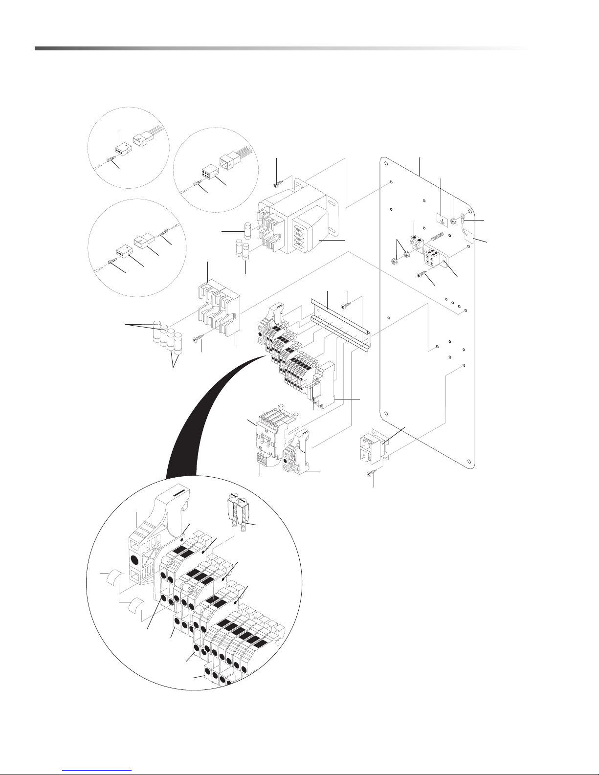
Electrical Panel - 208V 1PH
1
23
24
23
24
25
26
22
24
Timer
Option
Oil Skimmer
Auto Fill
Option
6
2
5
16
30
18
28
3
17
29
30
20
15
14
34
7
8
4
19
30
29
10
9
27
32
33
# 1.043-421.0
4
11
12
11
31
35
35
31
13
21
36
36
GROUND
48
CUDA 2848 Operator’s Manual 8.930 -369.0 - AG
Page 49
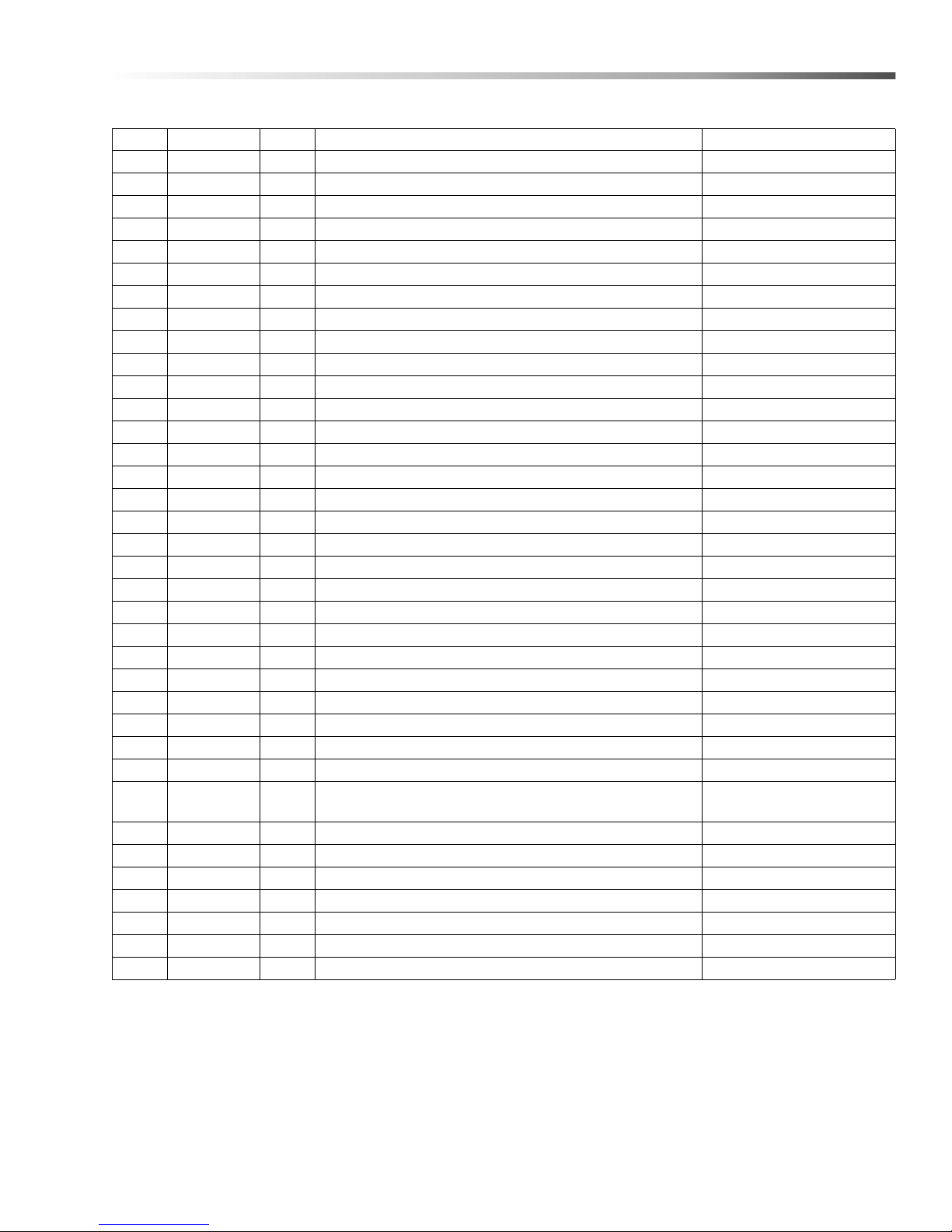
Electrical Panel - 208V 1PH
REF PART NO. QTY DESCRIPTION NOTES
1 8.750-867.0 1 CONTACTOR, 3 POLE, 45 AMPS
2 8.713-078.0 1 FUSE, 2 AMP FNM -2
3 8.713-086.0 1 GROUND, LUG 2 HOLE ALUM
4 9.804-595.0 2 END BRACKET, ENTRELEC, 103-002-26
5 8.713-286.0 2 FUSE, CLASS R 2 AMP FNQ-R-21
6 8.713-290.0 1 FUSE BLOCK (H2PR) 2-POLE
7 8.714-132.0 1 FUSE BLOCK 60A
8 8.750-876.0 1 OVERLOAD, 21.0-26.0 AMP
9 8.713-284.0 2 FUSE, CLASS R 30 AMP
10 8.713-294.0 2 FUSE, 45 AMP
11 8.716-398.0 9 TERMINAL BLOCK, BLUE INTRELEC
12 8.716-396.0 2 TERMINAL BLOCK, INTRELEC
13 8.755-016.0 1 TERMINAL BLOCK JUMPER, 2 POLE
14 8.753-367.0 1 RELAY, SPDT
15 8.753-368.0 1 RELAY, BASE
16 8.716-895.0 1 TRANSFORMER, 200/220/440V-120V, .200KVA
17 8.714-164.0 1 TERMINAL BLOCK, 2 POSITION (SURFACE) BL-BL
18 9.800-040.0 1 LABEL, GROUND SYMBOL
19 8.714-394.0 1 CONTACTOR, 3 POLE, 40 AMP
20 9.802-457.0 7" DIN RAIL, 35 MM
21 8.716-599.0 2 TERMINAL, GROUNDING, GREEN W/YELLOW
22 8.713-697.0 1 CONNECTOR, ELECT 6 PIN MALE
23 8.713-603.0 2 CONNECTOR, ELECT 3 PIN MALE
24 8.713-604.0 12 CONNECTOR, ELECT PIN FEMALE
25 8.713-656.0 1 CONNECTOR, ELECT 3 PIN FEMALE
26 8.713-768.0 3 CONNECTOR, ELECT PIN MALE
27 8.931-186.0 1 PANEL, ELECT, 2840/2848
28 8.716-375.0 2 TERMINAL RING TONGUE RC10-516
29 8.718-937.0 6
30 9.802-798.0 10 SCREW, #10 X 1/2", TEK HEX HEAD
31 8.716-399.0 2 END COVER, ENTRELEC, GRAY
32 9.802-778.0 1 NUT, WHIZ LOC, 5/16" FLANGE
33 9.802-775.0 2 NUT, 1/4" FLANGE NC
34 8.900-514.0 1 LABEL, 208V, 1 PH
35 8.716-400.0 2 END COVER, ENTRELEC, BLUE
36 9.804-609.0 18 MARKER BLANK
SCREW, #8 X 3/4" PHILLIPS, ZINC PLATED,
HEX TEK
49CUDA 2848 Operator’s Manual 8.930 -369.0 - AG
Page 50
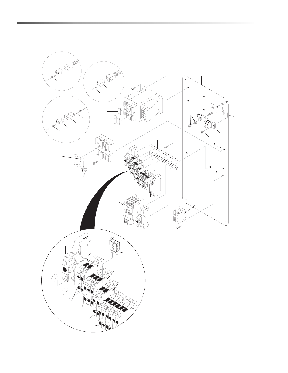
Electrical Panel - 230V 1PH
1
23
24
23
24
25
26
22
24
Timer
Option
Oil Skimmer
Auto Fill
Option
6
2
5
16
30
18
28
3
17
29
30
20
15
14
34
7
8
4
19
30
29
10
9
27
32
33
# 1.043-422.0
4
11
12
11
31
35
35
31
13
21
36
36
GROUND
50
CUDA 2848 Operator’s Manual 8.930 -369.0 - AG
Page 51
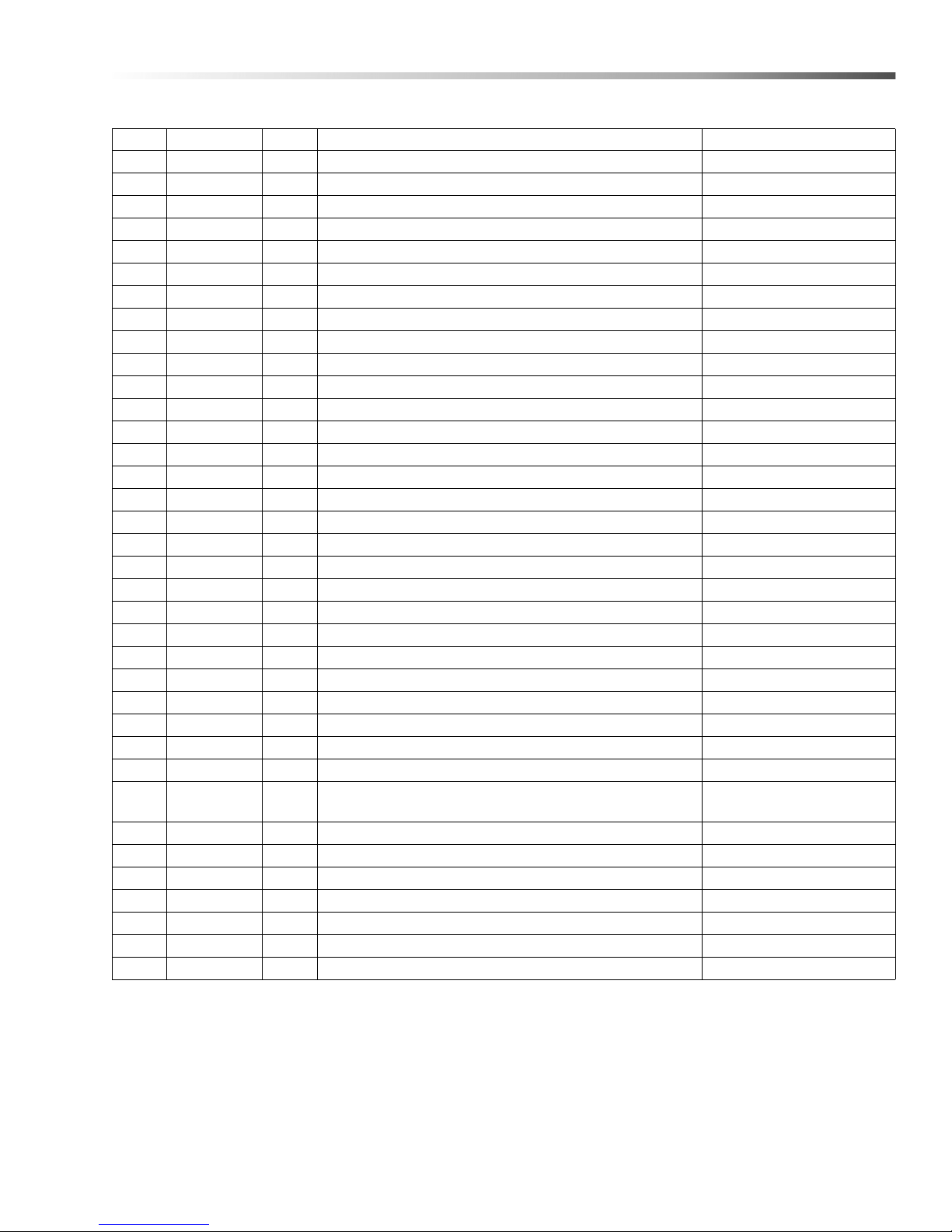
Electrical Panel - 230V 1PH
REF PART NO. QTY DESCRIPTION NOTES
1 8.750-867.0 1 CONTACTOR, 3 POLE, 45 AMPS
2 8.713-078.0 1 FUSE, 2 AMP FNM -2
3 8.713-086.0 1 GROUND, LUG 2 HOLE ALUM
4 9.804-595.0 2 END BRACKET, ENTRELEC, 103-002-26
5 8.713-286.0 2 FUSE, CLASS R 2 AMP FNQ-R-21
6 8.713-290.0 1 FUSE BLOCK (H2PR) 2-POLE
7 8.714-132.0 1 FUSE BLOCK 60A
8 8.750-876.0 1 OVERLOAD, 21.0-26.0 AMP
9 8.713-284.0 2 FUSE, CLASS R 30 AMP
10 8.713-294.0 2 FUSE, 45 AMP
11 8.716-398.0 9 TERMINAL BLOCK, BLUE INTRELEC
12 8.716-396.0 2 TERMINAL BLOCK, INTRELEC
13 8.755-016.0 1 TERMINAL BLOCK JUMPER, 2 POLE
14 8.753-367.0 1 RELAY, SPDT
15 8.753-368.0 1 RELAY, BASE
16 8.716-895.0 1 TRANSFORMER, 200/220/440V-120V, .200KVA
17 8.714-164.0 1 TERMINAL BLOCK, 2 POSITION (SURFACE) BL-BL
18 9.800-040.0 1 LABEL, GROUND SYMBOL
19 8.714-394.0 1 CONTACTOR, 3 POLE , 40 AMP
20 9.802-457.0 7" DIN RAIL, 35 MM
21 8.716-599.0 2 TERMINAL, GROUNDING, GREEN W/YELLOW
22 8.713-697.0 1 CONNECTOR, ELECT 6 PIN MALE
23 8.713-603.0 2 CONNECTOR, ELECT 3 PIN MALE
24 8.713-604.0 12 CONNECTOR, ELECT PIN FEMALE
25 8.713-656.0 1 CONNECTOR, ELECT 3 PIN FEMALE
26 8.713-768.0 3 CONNECTOR, ELECT PIN MALE
27 8.931-186.0 1 PANEL, ELECT, 2840/2848
28 8.716-375.0 2 TERMINAL RING TONGUE RC10-516
29 8.718-937.0 6
30 9.802-798.0 10 SCREW, #10 X 1/2", TEK HEX HEAD
31 8.716-399.0 2 END COVER, ENTRELEC, GRAY
32 9.802-778.0 1 NUT, WHIZ LOC, 5/16" FLANGE
33 9.802-775.0 2 NUT, 1/4" FLANGE NC
34 9.800-025.0 1 LABEL, 230V, 1 PH
35 8.716-400.0 2 END COVER, ENTRELEC, BLUE
36 9.804-609.0 18 MARKER BLANK
SCREW, #8 X 3/4" PHILLIPS, ZINC PLATED,
HEX TEK
51CUDA 2848 Operator’s Manual 8.930 -369.0 - AG
Page 52
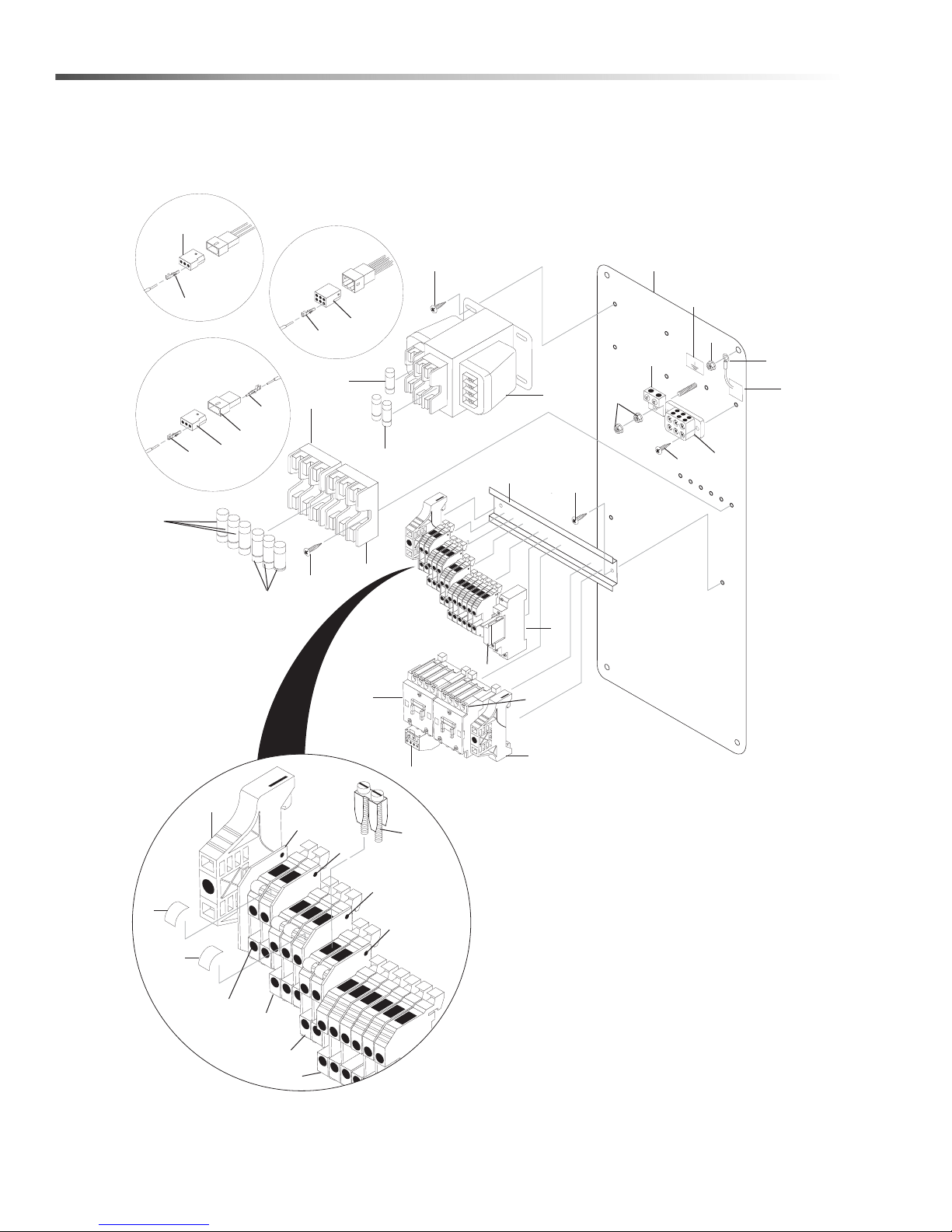
Electrical Panel - 208V 3PH
1
23
24
23
24
25
26
22
24
Timer
Option
Oil Skimmer
Auto Fill
Option
6
2
5
16
30
18
28
3
17
29
30
20
15
14
7
8
4
19
29
10
9
27
32
33
# 1.043-423.0
34
4
11
12
11
31
35
35
31
13
21
36
36
GROUND
52
CUDA 2848 Operator’s Manual 8.930 -369.0 - AG
Page 53
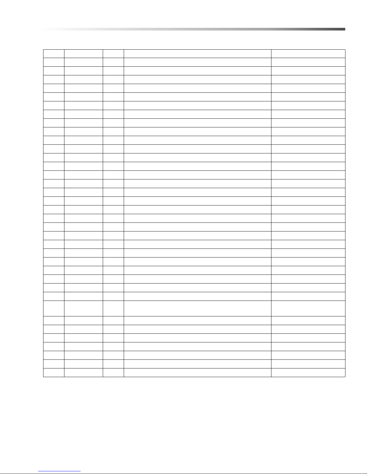
Electrical Panel - 208V 3PH
REF PART NO. QTY DESCRIPTION NOTES
1 8.750-864.0 1 CONTACTOR, 3 POLE, 16 AMPS
2 8.713-078.0 1 FUSE, 2 AMP FNM -2
3 8.713-086.0 1 GROUND, LUG 2 HOLE ALUM
4 9.804-595.0 2 END BRACKET, ENTRELEC, 103-002-26
5 8.713-286.0 2 FUSE, CLASS R 2 AMP FNQ-R-21
6 8.713-282.0 1 FUSE BLOCK, 3-POLE, 30A
7 8.713-282.0 1 FUSE BLOCK, 3-POLE, 30A
8 8.750-875.0 1 OVERLOAD, 14.5-18 AMP
9 8.713-293.0 3 FUSE, CLASS R 20 AMP FRN-R-20
10 8.713-291.0 3 FUSE, 30 AMP
11 8.716-398.0 9 TERMINAL BLOCK, BLUE INTRELEC
12 8.716-396.0 2 TERMINAL BLOCK, INTRELEC
13 8.755-016.0 1 TERMINAL BLOCK JUMPER, 2 POLE
14 8.753-367.0 1 RELAY, SPDT
15 8.753-368.0 1 RELAY, BASE
16 8.716-895.0 1 TRANSFORMER, 200-220-440V-120V, .200KVA
17 8.714-512.0 1 TERMINAL BLOCK, 3 POSITION
18 9.800-040.0 1 LABEL, GROUND SYMBOL
19 8.750-867.0 1 CONTACTOR, 3 POLE, 45 AMP
20 9.802-457.0 9" DIN RAIL, 35 MM
21 8.716-599.0 2 TERMINAL, GROUNDING, GREEN W/YELLOW
22 8.713-697.0 1 CONNECTOR, ELECT 6 PIN MALE
23 8.713-603.0 2 CONNECTOR, ELECT 3 PIN MALE
24 8.713-604.0 12 CONNECTOR, ELECT PIN FEMALE
25 8.713-656.0 1 CONNECTOR, ELECT 3 PIN FEMALE
26 8.713-768.0 3 CONNECTOR, ELECT PIN MALE
27 8.931-186.0 1 PANEL, ELECT, 2840/2848
28 8.716-375.0 2 TERMINAL RING TONGUE RC10-516
29 8.718-937.0 6
30 9.802-798.0 6 SCREW, #10 X 1/2", TEK HEX HEAD
31 8.716-399.0 2 END COVER, ENTRELEC, GRAY
32 9.802-778.0 1 NUT, WHIZ LOC, 5/16" FLANGE
33 9.802-775.0 2 NUT, 1/4" FLANGE, NL
34 8.900-515.0 1 LABEL, 208V, 3 PH
35 8.716-400.0 2 END COVER, ENTRELEC, BLUE
36 9.804-609.0 18 MARKER BLANK
SCREW, #8 X 3/4" PHILLIPS, ZINC PLATED,
HEX TEK
53CUDA 2848 Operator’s Manual 8.930 -369.0 - AG
Page 54
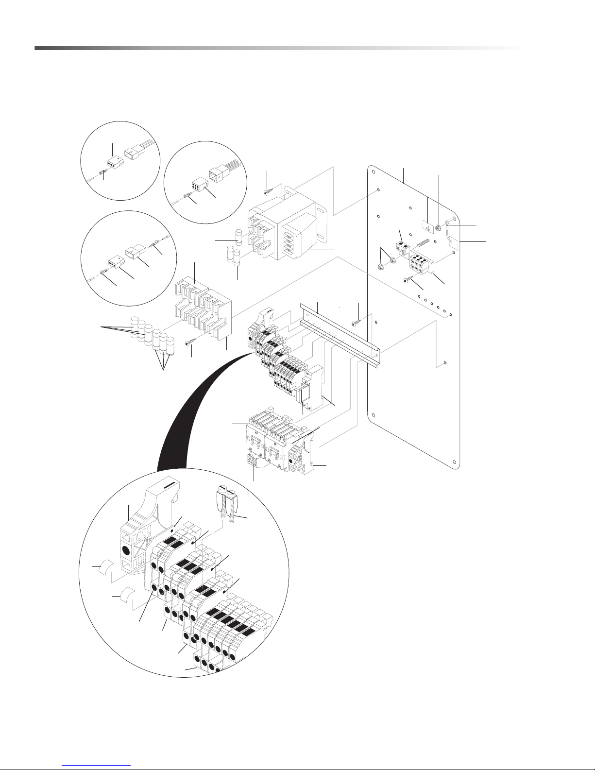
Electrical Panel - 230V 3PH
1
23
24
23
24
25
26
22
24
Timer
Option
Oil Skimmer
Auto Fill
Option
6
2
5
16
30
18
28
3
17
29
30
20
15
14
7
8
4
19
29
10
9
27
32
33
# 1.043-394.0
34
4
11
12
11
31
35
35
31
13
21
36
36
GROUND
54
CUDA 2848 Operator’s Manual 8.930 -369.0 - AG
Page 55
Electrical Panel - 230V 3PH
REF PART NO. QTY DESCRIPTION NOTES
1 8.750-864.0 1 CONTACTOR, 3 POLE, 16 AMPS
2 8.713-078.0 1 FUSE, 2 AMP FNM-2
3 8.713-086.0 1 GROUND, LUG 2 HOLE ALUM
4 9.804-595.0 2 END BRACKET, ENTRELEC, 103-002-26
5 8.713-286.0 2 FUSE, CLASS R 2 AMP FNQ-R-21
6 8.713-282.0 1 FUSE BLOCK (H2PR) 3-POLE
7 8.713-282.0 1 FUSE BLOCK (H2PR) 3-POLE
8 8.750-875.0 1 OVERLOAD, 14.5-18 AMP
9 8.713-293.0 3 FUSE, CLASS R 20 AMP FRN-R-20
10 8.713-291.0 3 FUSE, 30 AMP
11 8.716-398.0 9 TERMINAL BLOCK, BLUE INTRELEC
12 8.716-396.0 2 TERMINAL BLOCK, INTRELEC
13 8.755-016.0 1 TERMINAL BLOCK JUMPER, 2 POLE
14 8.753-367.0 1 RELAY, SPDT
15 8.753-368.0 1 RELAY, BASE
16 8.716-895.0 1 TRANSFORMER, 200/220/440V-120V, .200KVA
17 8.714-512.0 1 TERMINAL BLOCK, 3 POSITION
18 9.800-040.0 1 LABEL, GROUND SYMBOL
19 8.750-867.0 1 CONTACTOR, 3 POLE, 45 AMP
20 9.802-457.0 9" DIN RAIL, 35 MM
21 8.716-599.0 2 TERMINAL, GROUNDING, GREEN W/YELLOW
22 8.713-697.0 1 CONNECTOR, ELECT 6 PIN MALE
23 8.713-603.0 2 CONNECTOR, ELECT 3 PIN MALE
24 8.713-604.0 12 CONNECTOR, ELECT PIN FEMALE
25 8.713-656.0 1 CONNECTOR, ELECT 3 PIN FEMALE
26 8.713-768.0 3 CONNECTOR, ELECT PIN MALE
27 8.931-186.0 1 PANEL, ELECT, 2840/2848
28 8.716-375.0 2 TERMINAL RING TONGUE RC10-516
29 8.718-937.0 6
30 9.802-798.0 6 SCREW, #10 X 1/2", TEK HEX HEAD
31 8.716-399.0 2 END COVER, ENTRELEC, GRAY
32 9.802-778.0 1 NUT, WHIZ LOC, 5/16" FLANGE
33 9.802-775.0 2 NUT, 1/4 FLANGE NC
34 9.800-023.0 1 LABEL, 230 V, 3 PH
35 8.716-400.0 2 END, COVER, ENTRELEC, BLUE
36 9.804-609.0 18 MARKER BLANK
SCREW, #8 X 3/4" PHILLIPS, ZINC PLATED,
HEX TEK
55CUDA 2848 Operator’s Manual 8.930 -369.0 - AG
Page 56
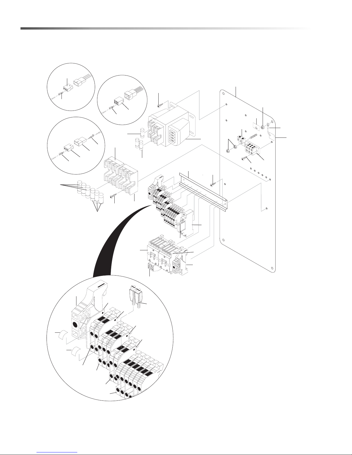
Electrical Panel - 460V 3PH
1
23
24
23
24
25
26
22
24
Timer
Option
Oil Skimmer
Auto Fill
Option
6
2
5
16
30
18
28
3
17
29
30
20
15
14
7
8
4
1
29
10
9
27
32
33
# 1.043-424.0
34
4
11
12
11
31
19
19
31
13
21
35
35
GROUND
56
CUDA 2848 Operator’s Manual 8.930 -369.0 - AG
Page 57

Electrical Panel - 460V 3PH
REF PART NO. QTY DESCRIPTION NOTES
1 8.750-864.0 2 CONTACTOR, 3 POLE, 16 AMPS
2 8.713-078.0 1 FUSE, 2 AMP FNM-2
3 8.713-086.0 1 GROUND, LUG 2 HOLE ALUM
4 9.804-595.0 2 END BRACKET, ENTRELEC, 103-002-26
5 8.713-080.0 2 FUSE, CLASS R 1 AMP
6 8.713-061.0 1 FUSE BLOCK (C3P) 3-POLE
7 8.713-061.0 1 FUSE BLOCK (C3P) 3-POLE
8 8.750-873.0 1 OVERLOAD, 5.5-8.5 AMP
9 8.713-067.0 3 FUSE, CLASS CC 12 AMP
10 8.713-063.0 3 FUSE, CLASS CC 15 AMP
11 8.716-398.0 9 TERMINAL BLOCK, BLUE INTRELEC
12 8.716-396.0 2 TERMINAL BLOCK, INTRELEC
13 8.755-016.0 1 TERMINAL BLOCK JUMPER, 2 POLE
14 8.753-367.0 1 RELAY, SPDT
15 8.753-368.0 1 RELAY, BASE
16 8.716-895.0 1 TRANSFORMER, 200/220/440V-120V, .200KVA
17 8.714-512.0 1 TERMINAL BLOCK, 3 POSITION
18 9.800-040.0 1 LABEL, GROUND SYMBOL
19 8.716-400.0 2 END COVER ENTRELEC, BLUE
20 9.802-457.0 9" DIN RAIL, 35 MM
21 8.716-599.0 2 TERMINAL, GROUNDING, GREEN W/YELLOW
22 8.713-697.0 1 CONNECTOR, ELECT 6 PIN MALE
23 8.713-603.0 2 CONNECTOR, ELECT 3 PIN MALE
24 8.713-604.0 12 CONNECTOR, ELECT PIN FEMALE
25 8.713-656.0 1 CONNECTOR, ELECT 3 PIN FEMALE
26 8.713-768.0 3 CONNECTOR, ELECT PIN MALE
27 8.931-186.0 1 PANEL, ELECT, 2840/2848
28 8.716-375.0 2 TERMINAL RING TONGUE RC10-516
29 8.718-937.0 6
30 9.802-798.0 6 SCREW, #10 X 1/2", TEK HEX HEAD
31 8.716-399.0 2 END COVER, ENTRELEC, GRAY
32 9.802-778.0 1 NUT, WHIZL OCK, 5/16" FLANGE
33 9.802-775.0 2 NUT, 1/4 FLANGE NC
34 9.800-024.0 1 LABEL, 460V, 3 PH
35 9.804-609.0 18 MARKER BLANK
SCREW, #8 X 3/4" PHILLIPS, ZINC PLATED,
HEX TEK
57CUDA 2848 Operator’s Manual 8.930 -369.0 - AG
Page 58
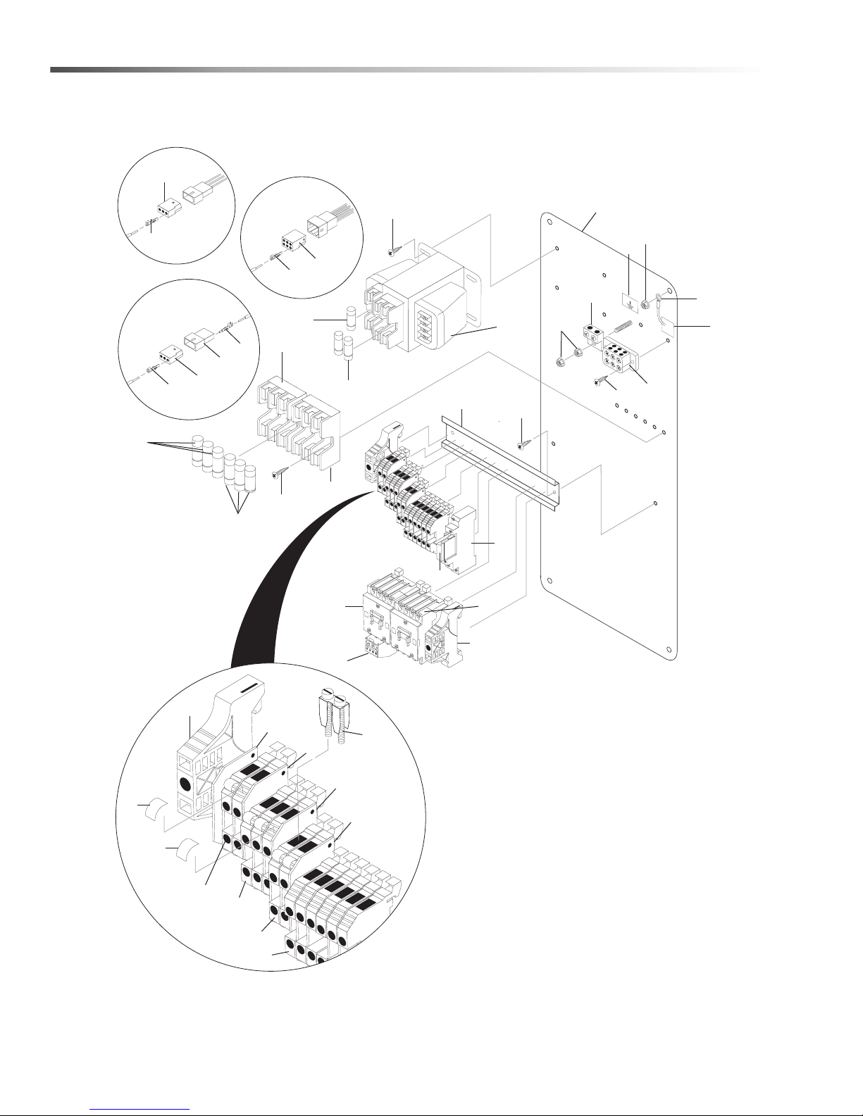
Electrical Panel - 575V 3PH
1
23
24
23
24
25
26
22
24
Timer
Option
Oil Skimmer
Auto Fill
Option
6
2
5
16
30
18
28
3
17
29
30
20
15
14
7
8
4
1
29
10
9
27
33
32
1.043-425.0
34
4
11
12
11
31
19
19
31
13
21
35
35
GRO
UND
58
CUDA 2848 Operator’s Manual 8.930 -369.0 - AG
Page 59

Electrical Panel - 575V 3PH
REF PART NO. QTY DESCRIPTION NOTES
1 8.750-864.0 2 CONTACTOR, 3 POLE, 16 AMPS
2 8.713-078.0 1 FUSE, 2 AMP FNM-2
3 8.713-086.0 1 GROUND, LUG 2 HOLE ALUM
4 9.804-595.0 2 END BRACKET, ENTRELEC, 103-002-26
5 8.713-080.0 2 FUSE, CLASS R 1 AMP
6 8.713-061.0 1 FUSE BLOCK (C3P) 3-POLE
7 8.713-061.0 1 FUSE BLOCK (C3P) 3-POLE
8 8.750-872.0 1 OVERLOAD, 4.0-6.3 AMP
9 8.713-066.0 3 FUSE, CLASS CC 10 AMP
10 8.713-067.0 3 FUSE, CLASS CC 12 AMP
11 8.716-398.0 9 TERMINAL BLOCK, BLUE INTRELEC
12 8.716-396.0 2 TERMINAL BLOCK, INTRELEC
13 8.755-016.0 1 TERMINAL BLOCK JUMPER, 2 POLE
14 8.753-367.0 1 RELAY, SPDT
15 8.753-368.0 1 RELAY, BASE
16 8.713-907.0 1 TRANSFORMER, 200VA 575V/115V
17 8.714-512.0 1 TERMINAL BLOCK, 3 POSITION
18 9.800-040.0 1 LABEL, GROUND SYMBOL
19 8.716-400.0 2 END COVER ENTRELEC, BLUE
20 9.802-457.0 9" DIN RAIL, 35 MM
21 8.716-599.0 2 TERMINAL, GROUNDING, GREEN W/YELLOW
22 8.713-697.0 1 CONNECTOR, ELECT 6 PIN MALE
23 8.713-603.0 2 CONNECTOR, ELECT 3 PIN MALE
24 8.713-604.0 12 CONNECTOR, ELECT PIN FEMALE
25 8.713-656.0 1 CONNECTOR, ELECT 3 PIN FEMALE
26 8.713-768.0 3 CONNECTOR, ELECT PIN MALE
27 8.931-186.0 1 PANEL, ELECT, 2840/2848
28 8.716-375.0 2 TERMINAL RING TONGUE RC10-516
29 8.718-937.0 6
30 9.802-798.0 6 SCREW, #10 X 1/2", TEK HEX HEAD
31 8.716-399.0 2 END COVER, ENTRELEC, GRAY
32 9.802-778.0 1 NUT,WHIZLOCK, 5/16" FLANGE
33 9.802-775.0 2 NUT, 1/4 FLANGE NC
34 8.900-516.0 1 LABEL, 575V, 3 PH
35 9.804-609.0 18 MARKER BLANK
SCREW, #8 X 3/4" PHILLIPS, ZINC PLATED,
HEX TEK
59CUDA 2848 Operator’s Manual 8.930 -369.0 - AG
Page 60
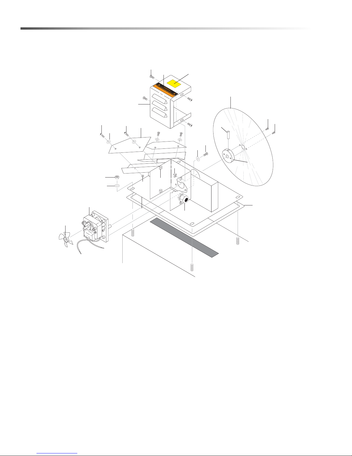
Oil Skimmer
1
2
1
1
4
6
13
8
7
7
15
10
10
13
12
11
1
16
5
14
17
18
3
19
9
KEEP
DRY
60
CUDA 2848 Operator’s Manual 8.930 -369.0 - AG
Page 61

Oil Skimmer
REF PART NO. QTY DESCRIPTION NOTES
1 8.718-810.0 11 SCREW, 10/32" X 1/2", WHIZ LOC FLANGE
2 8.913-733.0 1 COVER, MOTOR, DISC SKIMMER SS
3 9.800-016.0 1 LABEL, DISC. POWER SUPPLY
4 9.804-102.0 2 BLADE, WIPER, DISC SKIMMER SS
5 9.802-776.0 4 NUT, 5/16 ESNA
6 8.918-672.0 1 DISC, SKIMMER SS
7 9.802-791.0 4 NUT, CAGE, 10/32" X 16 GA
8 9.802-514.0 1 STRAIN RELIEF, STRT, LQ TITE
9 9.804-374.0 1 LABEL, KEEP DRY
10 8.904-676.0 1 MOTOR, DISC SKIMMER
11 8.719-987.0 1 HUB, DISC MOUNT, DISC SKIMMER
12 8.719-068.0 1 PIN, ROLL 1/8" X 1" STEEL
13 9.804-564.0 2 SCREW, 6-22 X 1/2"
14 8.718-980.0 4 WASHER, 5/16 FLAT
15 8.913-751.0 1 OIL SKIMMER, LARGE
- 8.921-923.0 1 OIL SKIMMER, LARGE SS
16 8.718-568.0 3 WASHER, 1/4" SEALING, STAINLESS
17 9.804-567.0 4 NUT, 10/32 ESNA
- 8.754-307.0 4 NUT, 10/32 ESNA, SS
18 9.804-621.0 1 GASKET, SKIMMER
19 8.718-968.0 4 WASHER, #10 FLAT ZINC PLT
- 8.754-300.0 4 WASHER, FLAT, #10 18-8, SS
61CUDA 2848 Operator’s Manual 8.930 -369.0 - AG
Page 62
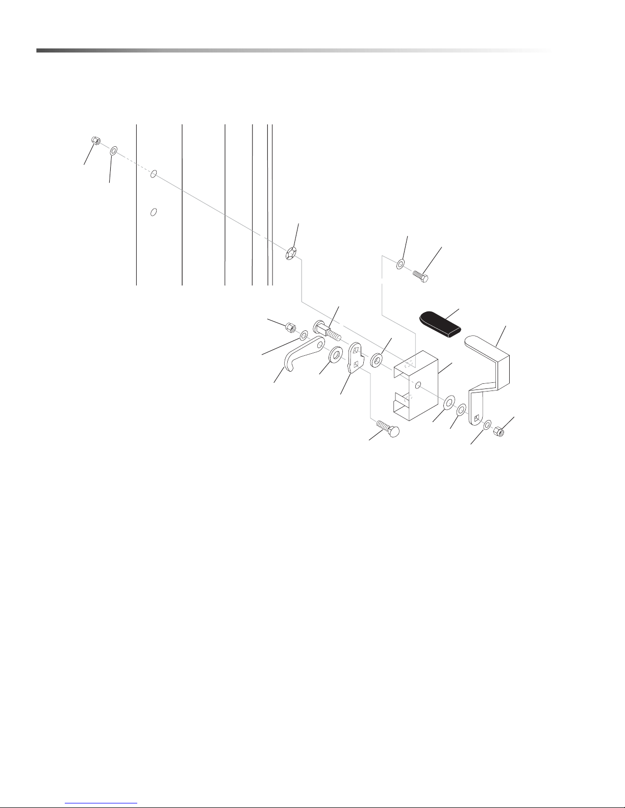
Door Latch
1
10
16
11
17
5
4
15
12
7
8
6
2
3
14
10
11
9
13
18
62
CUDA 2848 Operator’s Manual 8.930 -369.0 - AG
Page 63

Door Latch
REF PART NO. QTY DESCRIPTION NOTES
1 8.922-114.0 1 HANDLE, LATCH, SS
2 8.753-733.0 1 WASHER, 7/16" BRASS
3 8.751-823.0 1 WASHER, 7/16" FLAT SS
4 9.802-805.0 1 WASHER, 5/16" FLAT SS
5 9.802-777.0 1 NUT, 5/16-18, ESNA, SS
6 8.753-710.0 1 BOLT, CARRIAGE, 1/4 X 1" SS
7 8.922-111.0 1 LINK, LATCH, SS
8 8.921-274.0 1 SPACER, BRAKE LINK, 80
9 8.922-113.0 1 HOOK, DOOR, LATCH, SS
10 9.802-774.0 2 NUT, 1/4" ESNA, SS
11 8.718-965.0 3 WASHER, 1/4" FLAT SS
12 8.753-722.0 1 BOLT, 5/16-18, FH CARRIAGE CUSTOM, S/S
13 8.922-110.0 1 WASHER, 1.125' X .1875, SS
14 9.804-370.0 1 SLEEVE, LATCH HANDLE, VINYL
15 8.923-685.0 1 FRAME, DOOR LATCH, HD
16 8.718-568.0 2 WASHER, 1/4" FLAT SS SEALING RUBBER
17 8.718-603.0 2 BOLT, 1/4" X 3/4", NC HH SS
18 8.718-976.0 2 WASHER, 1/4" RETAINER
63CUDA 2848 Operator’s Manual 8.930 -369.0 - AG
Page 64

8.930-369.0 • Printed in U.S.A.
 Loading...