

Page 1
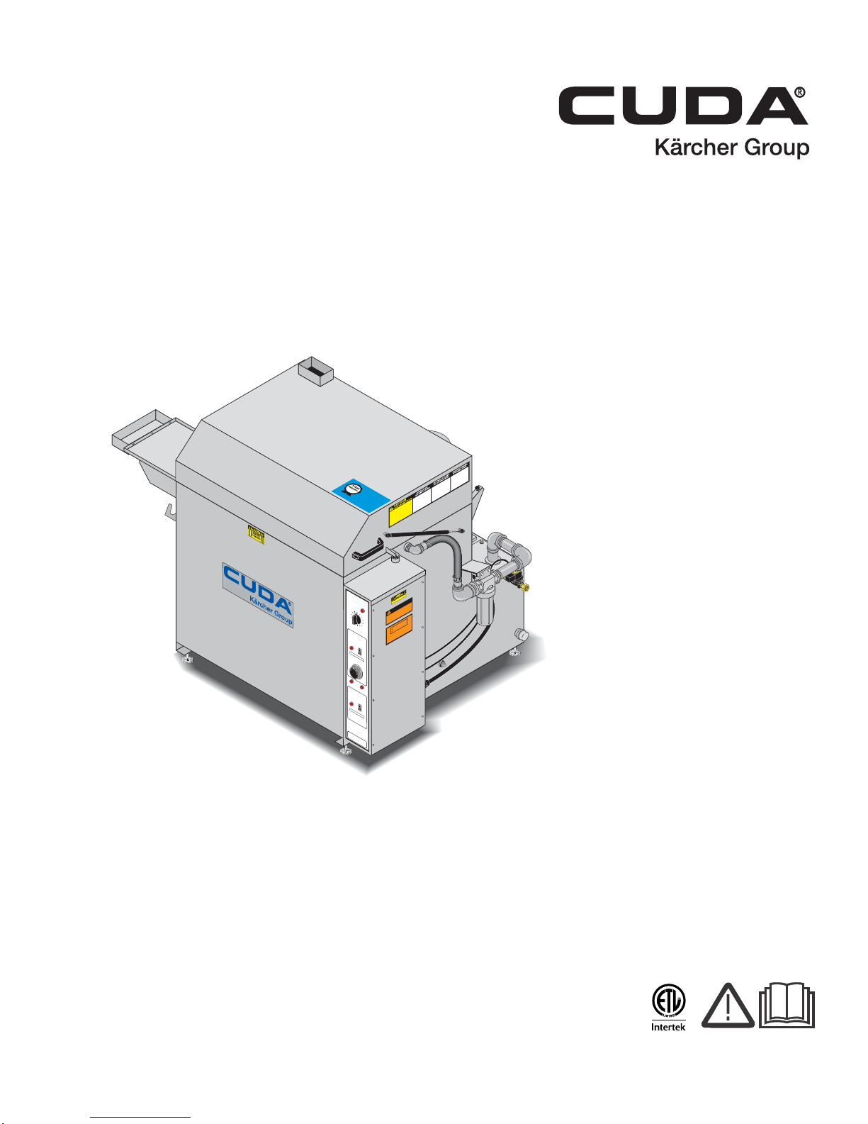
SJ-15 Series
W
A
SH CYCLE
HEA
T
ER
SJ-15
OIL SKIMME
R
LO
W
WA
TE
R
V
O
L
T
A
GE
ON
1
OFF
0
TI
MER
COLECT
OR DE A
CEITE
ECUMEUR D'HUIL
E
TIMER O
VERIDE
NO
TICE / A
T
ENCION /
A
VI
S
TIMER O
VERIDE
TURN
P
A
ST 10
MINUTES
CALEN
T
A
DOR
CH
A
U
FFE-EA
U
NO
TICE /
A
T
ENCION /
A
V
I
S
CONTR
OLADOR DE
TEMPO FUE
RA DE
SE
R
V
I
VO
ANNUL
A
T
ION DE MINUTERI
E
CONTROLADOR DE
TEMPO FUE
RA DE SER
VIV
O
ANNUL
A
T
ION DE MIN
UTERIE
MINUTOS
CYCLO DE
a
aa LA
V
ADO
CYCLE DE LA
V
A
GE
POCA
A
G
U
A
PEU D'EA
U
60
50
40
30
20
1
0
0
HOLD
ON
1
OFF
0
TIME
R
OF
F
F°
10
0
2
0
3
3
20
0
165
130
5
9
2
3
5
270
30
0
WARNING
MA
CHINE MUST BE CO
NNECTED
T
O
A
PR
OPERL
Y SIZED LOCKABL
E DISCONEC
T
.
I
NS
T
ALLA
TION MUST COM
P
L
Y
WI
T
H
N
E
C
CO
D
E
.
W
ARNIN
G
FOR SUPPL
Y
CONNECTION USE
WIRES
A
CCEPT
ABLE FOR
A
T
LEA
ST 90 DEGREES C
ENTIGRADE
.
DO NO
USE BELO
W GRADE FLOOR
OR GRADE LEVEL
.
ATTENTION
USE
ON
L
Y
CU
D
A AP
P
R
O
VED
DETERGENTS
T
O EXTEND
LABO
R
W
ARRA
NTY
T
O 1
-Y
EAR
!
MIX DETERGENTS 1 LB (1/2 KG) P
ER
5-GALLONS
(15 LITERS) OF
WA
T
E
R
For C
U
D
A Ap
p
r
o
ved Dete
r
g
e
n
ts v
i
s
i
t
http:
//ww
w
.cudau
sa.com or
call 888-319-0
882
9.807-513.0
9
0D
AY
L
A
B
O
R
W
A
R
RA
N
T
Y
EXTEND
S
TO
1-Y
EA
R
WITH
E
XC
L
US
I
VE USE
O
F
CU
D
A
DE
T
ER
GENT
S
LI
MIT
E
D
Operator’ s Manual
Automatic Parts Washer
Top-Load
MODELS: 1.043-458.0
1.043-459.0
1.043-460.0
1.043-461.0
1.043-462.0
1.043-463.0
For the Cuda Dealer nearest you,
consult our web page at
www.CudaUSA.com
9.801-128.0-H 05/23/17
Page 2
Machine Data Label
2 Cuda SJ-15 Series Operator’s Manual 9.801-128.0 - H
Page 3

Machine Data Label. . . . . . . . . . . . . . . . . . . . . . . . . .2
Table of Contents . . . . . . . . . . . . . . . . . . . . . . . . . . .3
How To Use This Manual . . . . . . . . . . . . . . . . . . . . .4
Safety
Introduction & Safety Information . . . . . . . . . . . . . . .5
General Safety Information. . . . . . . . . . . . . . . . . . . .6
Electrical Safety . . . . . . . . . . . . . . . . . . . . . . . . . . . .7
Standard Safety Features. . . . . . . . . . . . . . . . . . . . .7
Operations
Specifications . . . . . . . . . . . . . . . . . . . . . . . . . . . . . .8
Component Identification . . . . . . . . . . . . . . . . . . . .10
Installation. . . . . . . . . . . . . . . . . . . . . . . . . . . . . . . .11
Pre-start Checklist. . . . . . . . . . . . . . . . . . . . . . . . . .12
Operating Instructions. . . . . . . . . . . . . . . . . . . . . . .12
Maintenance
Oil Removal . . . . . . . . . . . . . . . . . . . . . . . . . . . . . .13
Sludge Removal . . . . . . . . . . . . . . . . . . . . . . . . . . .13
Spray Arm. . . . . . . . . . . . . . . . . . . . . . . . . . . . . . . .13
Filters . . . . . . . . . . . . . . . . . . . . . . . . . . . . . . . . . . .13
Detergent and Additives . . . . . . . . . . . . . . . . . . . . .13
Options . . . . . . . . . . . . . . . . . . . . . . . . . . . . . . . . . .14
Automatic Water Fill . . . . . . . . . . . . . . . . . . . . . . . .15
Caster Wheel . . . . . . . . . . . . . . . . . . . . . . . . . . . . .15
Small Parts Basket . . . . . . . . . . . . . . . . . . . . . . . . .15
Service Tray . . . . . . . . . . . . . . . . . . . . . . . . . . . . . .15
Tool Basket with Cleaning Tools. . . . . . . . . . . . . . .15
Wastewater Drum Evaporator. . . . . . . . . . . . . . . . .15
Troubleshooting . . . . . . . . . . . . . . . . . . . . . . . . . . .16
Table of Contents
Parts
Cuda SJ - 15. . . . . . . . . . . . . . . . . . . . . . . . . . . . . 20
Electrical Panel. . . . . . . . . . . . . . . . . . . . . . . . . . . 26
Oil Skimmer . . . . . . . . . . . . . . . . . . . . . . . . . . . . . 30
Detail Brush . . . . . . . . . . . . . . . . . . . . . . . . . . . . . 32
Cuda SJ-15 Series Operator’s Manual 9.801-128.0 - H
3
Page 4
How To Use This Manual
Model:
Date of Purchase:
Serial Number:
Dealer:
Address:
Phone Number:
Sales Representative:
This manual contains the following sections:
• How to Use This Manual
•Safety
• Operations
• Maintenance
• Parts List
The HOW TO USE THIS MANUAL section will tell you
how to find important information for ordering correct
repair parts.
Parts may be ordered from authorized dealers. When
placing an order for parts, the machine model and
machine serial number are important. Refer to the
MACHINE DATA box which is filled out during the
installation of your machine. The MACHINE DATA box
is located on the inside of the front cover of this manual.
The model and serial number of your machine is
located on the back of the machine.
The SAFETY section contains important information
regarding hazardous or unsafe practices of the
machine. Levels of hazards are identified that could
result in product damage, personal injury, or severe
injury resulting in death.
The OPERAT IONS section is to familiarize the operator
with the operation and function of the machine.
The MAINTENANCE section contains preventive maintenance to keep the machine and its components in
good working condition. They are listed in this general
order:
• Oil Removal
• Sludge Removal
• Spray Arm
• Filters
• Detergent and Additives
• Options
• Automatic Water Fill
•Caster Wheel
• Small Parts Basket
•Service Tray
• Tool Basket with Cleaning Tools
• Wastewater Drum Evaporator
• Alignment T ool
• Troubleshooting
The PARTS LIST section contains assembled parts
illustrations and corresponding parts list. The parts lists
include a number of columns of information:
4
Cuda SJ-15 Series Operator’s Manual 9.801-128.0 - H
• REF – column refers to the reference number
on the parts illustration.
• PART NO. – column lists the part number for
the part.
• QTY – column lists the quantity of the part used
in that area of the machine.
• DESCRIPTION – column is a brief description
of the part.
• NOTES – column for information not noted by
the other columns.
NOTE: If a service or option kit is installed on your
machine, be sure to keep the KIT INSTRUCTIONS
which came with the kit. It contains replacement parts
numbers needed for ordering future parts.
NOTE: The manual part number is located on the
lower right corner of the front cover.
Page 5

Introduction & Safety Information
Thank you for purchasing a CUDA SJ-15.
This manual covers the operation and maintenance of
the SJ-15 Parts Washer. All information in this manual
is based on the latest product information available at
the time of printing.
CUDA reserves the right to make changes at any time
without incurring any obligation.
Owner/User Responsibility:
The owner and/or user must have an understanding of
the manufacturer’s operating instructions and warnings
before using this CUDA machine. Warning information
should be emphasized and understood. If the operator
is not fluent in English, the manufacturer’s instructions
and warnings shall be read to and discussed with the
operator in the operator’s native language by the
purchaser/owner, making sure that the operator
comprehends its contents.
Owner and/or user must study and maintain for future
reference the manufacturers’ instructions.
Safety
Save these Instructions
This manual should be considered a permanent par t of
the machine and should remain with it if machine is
resold.
When ordering parts, please specify model and serial
number . Use only identical replacement parts.
This machine is to be used only by trained
operators.
Cuda SJ-15 Series Operator’s Manual 9.801-128.0 - H
5
Page 6
Safety
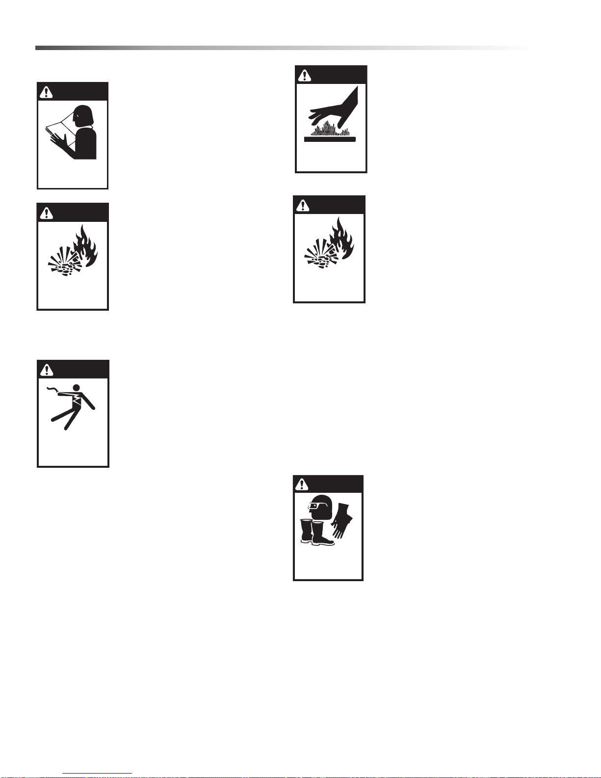
WARNING
EXTREMELY HOT:
USE CAUTION WHEN
OPENING LID
WARNING
RISK OF EXPLOSION:
AVOID FLAMMABLE
LIQUIDS.
WARNING
USE PROTECTIVE
EYE WEAR, GLOVES
AND FOOTWEAR
WHEN OPERATING.
DANGER
KEEP WATER
SPRAY AWAY FROM
ELECTRICAL WIRING.
WARNING
READ OPERATOR’S
MANUAL THOROUGHLY
PRIOR TO USE.
OPERATIONS
SAFETY
MAINTENANCE
WARNING
RISK OF EXPLOSION:
AVOID FLAMMABLE
LIQUIDS.
General Safety Information
WARNING: To reduce the risk of
injury, read operating instructions
carefully before using.
1. Read the owner’s manual thoroughly. Failure to follow instructions could cause a malfunction
of the parts washer and result in
death, serious bodily injury and/
or property damage.
WARNING: This is a heated parts
cleaner. Use only nonflammable,
noncombustible, water-based
cleaning compounds in this
machine. Do not fill or contaminate with any flammable or
combustible material such as
gasoline, alcohol, mineral spirits,
etc. Drain parts to be cleaned of
any combustible or flammable
material before placing inside cabinet. Failure to
observe this warning will create an extremely
hazardous condition.
DANGER: Keep water away from
electric wiring or fatal electric
shock may result.
2. All installations must comply
with local codes. Contact your
electrician, plumber, utility
company or the selling dealer for
specific details.
Install the machine in compli-
ance with the National Electric Code. Connect to a
properly sized lockable disconnect and ground
machine using the grounding stud inside the main
electrical panel.
3. Do not touch machine with wet hands or while
standing in water. Always disconnect the power
before servicing.
4. Never make adjustments on machine while it is in
operation except those prescribed in this manual.
WARNING: Use extreme caution
when opening the door of this
parts washer . Hot water/detergent
vapors will be emitted. Stand
Back! Hot cleaning solution could
cause serious injury.
5. Do not allow high concentrations of flammable fluids, acids,
or caustics to be introduced into
this machine.
WARNING: Flammable liquids can
create fumes which can ignite
causing property damage or
severe injury.
6. Do not locate this machine in the
vicinity of any flammable vapors,
liquids or solids.
7. Before servicing the machine,
refer to all safety data sheets
(SDS’s) on the material identified in the waste
stream. You must comply with all warnings and
wear all protective clothing stated on the SDS.
8. When the machine is working, do not cover or
place in a closed space where ventilation is insufficient. Avoid installing machines in small confined
areas.
9. In cold climates, this parts washer will freeze if not
in operation and must be located in a heated enclosure.
10. Running this machine without water will damage
the heating elements and will void the warranty.
WARNING: Eye protection , gloves
and foot protection must be worn
while loading and unloading parts.
11. Eye protection, gloves, foot
protection and other safety
devices must be worn when
loading and unloading parts to
be cleaned.
6
Cuda SJ-15 Series Operator’s Manual 9.801-128.0 - H
Page 7

Safety
WARNING: Slips and falls from wet surfaces could
cause serious injury.
12. Use caution when lifting items in and out of parts
basket to prevent back injuries.
13. Always ensure that your parts washer is clean.
Pump and heating elements could be damaged by
continued build-up of sludge.
14. Check water level daily. Never allow water level to
drop below pump inlet screen or heating elements.
15. Before discarding the spent washing solution,
check with your local EPA or sewer district for
disposal regulations.
16. Do not operate the machine with the lid or door
open and do not override the safety switch.
17. After the machine stops, wait 10 seconds before
opening the lid or door.
Electrical Safety
DANGER: Ground equipment before connecting to
the electrical power supply. Failure to ground
equipment could result in a severe or fatal electrical shock.
Standard Safety Features
The SJ-15 uses electricity to operate. This can be fatal
if not handled properly. For this reason, the
SJ-15 has been designed with safety in mind. The
following are standard safety features you will find.
1. One Hour Wash Timer and Indicator Light
This switch insures that the parts washer will turn
off the pump at a specific elapsed time.
2. Low Water Float Switch and Indicator Light
This float switch insures that there is water
covering the heating element. Before the water
level drops and begins to expose the heating
element, the low water float switch turns off the
heaters and wash pump and turns on an indicator
light.
3. 7-Day Programmable Heater Timer
The timer conserves energy by turning heating
elements on and off at operator set times.
4. Temperature Control
The high temperature control monitors the internal
temperature of the parts washer and maintains
water temperature at prescribed set point.
DANGER: Do not ground to a gas supply line.
DANGER: To avoid dangerous or fatal electric
shock, disconnect the power to the equipment
before working on any electrical connection or
making any repairs.
DANGER: Supply voltage must be within ±10% of
the nameplate voltage. Incorrect volta ge can cause
a fire or seriously damage the equipment and void
the warranty. If in doubt, consult a licensed electrician.
DANGER: Only connect the equipment to a
dedicated circuit with no other equipment on it.
Cuda SJ-15 Series Operator’s Manual 9.801-128.0 - H
7
Page 8
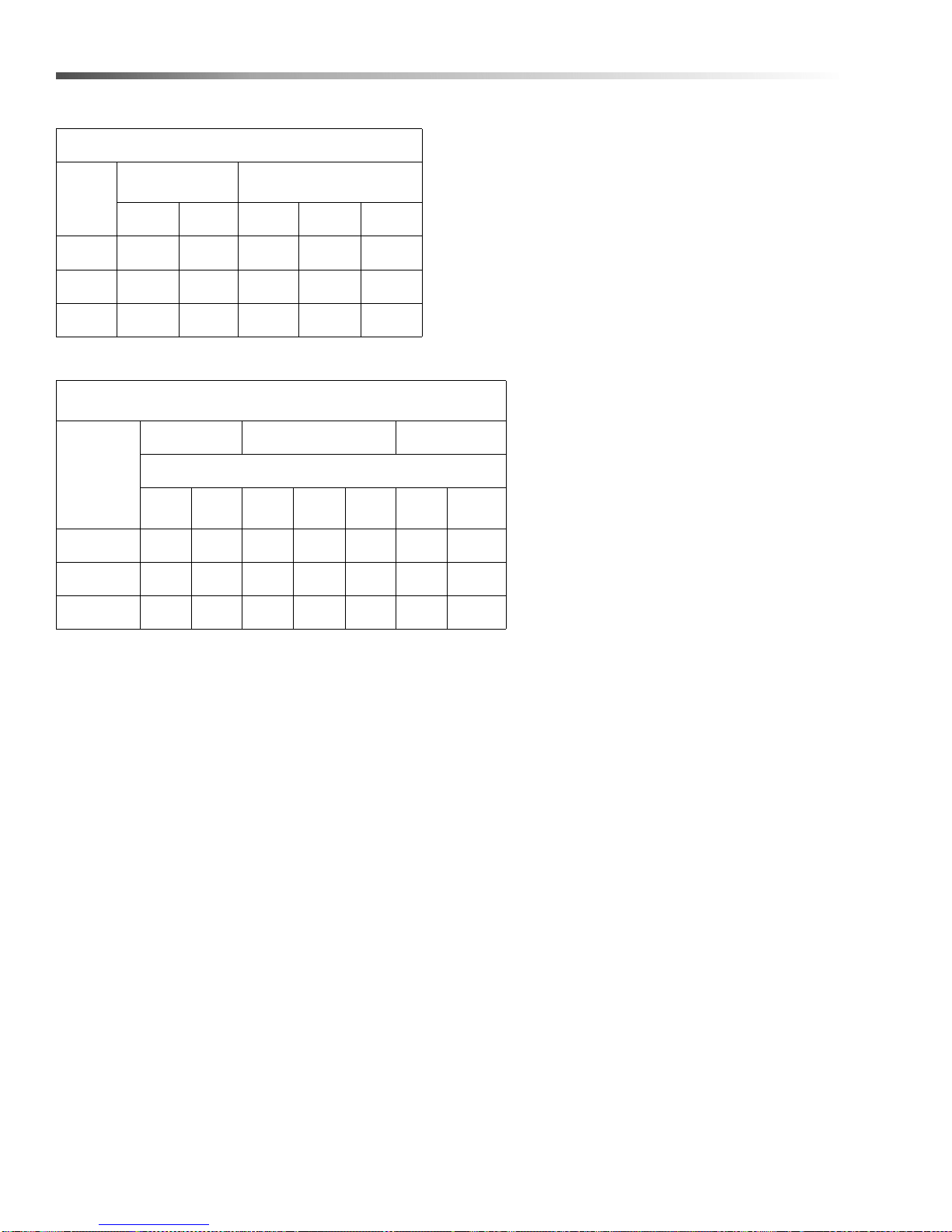
Operations
Specifications
Amperage Conversion
Volts Single
Watts
4500 37.5 18.8 9.38 10.84 5.42
5000 41.7 20.8 10.42 12.1 6.1
6000 50.0 25.0 12.50 14.50 7.2
Kw Rating
of Heater
4.5 3.78 4.13 3.38 3.78 4.14 3.78 4.14
5.0 4.20 4.59 3.5 4.2 4.6 4.2 4.6
7.5 6.30 6.89 5.6 6.3 6.9 6.3 6.
Phase
120 240 480 240 480
Ratings Of Listed Heater Voltages
Operated On Other Voltages
120 Volts 240 Volts 480 Volts
Output KW of Heater When Operated On
110
Volts
115
Volts
Volts 3 Phase
Balanced Load
208
Volts
220
Volts
230
Volts
440
Volts
460
Volts
8
Cuda SJ-15 Series Operator’s Manual 9.801-128.0 - H
Page 9
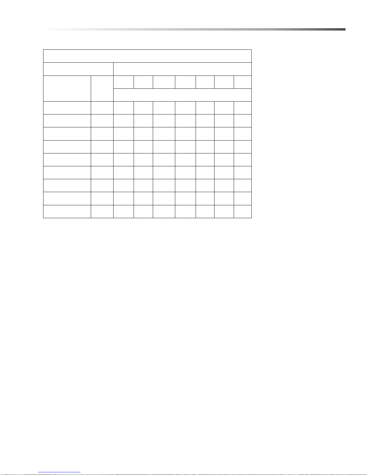
Kilowatt Hours to Heat Water
Amount of Liquid Temperature Rise °F
20° 40° 60° 80° 100° 120° 140°
Cu.Ft. Gal.
Kilowatts to heat in one hour
4.0 30 1.6 3.2 4.8 6.4 8 9.6 12
5.3 40 2.1 4 6.4 8.5 11 13 15
6.7 50 2.7 5.4 8 10.7 13 16 19
8.0 60 3.3 6.4 9.6 12.8 16 19 22
9.4 70 3.7 7.5 11.2 15 19 22 26
10.7 80 4.3 8.5 13 17 21 26 30
12.0 90 5 10 14.5 19 24 29 34
13.4 100 5.5 11 18 21 27 32 37
Operations
16.7 125 7 13 20 27 33 40 4
Cuda SJ-15 Series Operator’s Manual 9.801-128.0 - H
9
Page 10
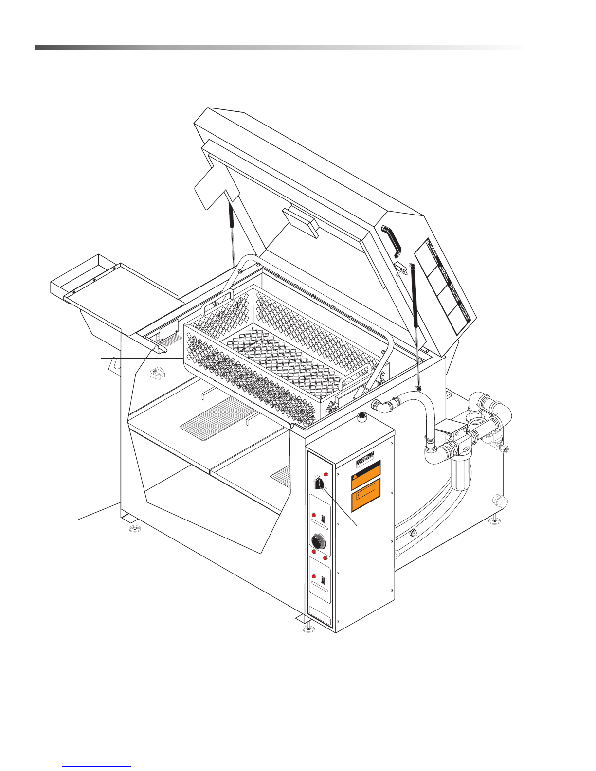
Operations
Lid
Wash Timer
Parts
Basket
W
ater
Tank
Component Identification
WASH CYCL
CYCLO DEa
CYCLE
MINUTES
MI
HOLD
60
50
40
TURN PAST 10
HEATER
CALENTADOR
CHAUFFE-EAU
NOTICE / ATENCION / AVI
CONTROLADOR
TIMER OVERID
DE TEMPO FU
ANNULATION D
5
23
20
0
0
27
0
30
F°
10-020
33
F
OF
LOW WATE
POCA AGUA
PEU D'EA
R
U
OIL SKIMMER
COLECTOR DE ACEITE
ECUMEUR D'HUILE
NOTICE / ATENCION / AVIS
CONTROLADOR D
TIMER OVERID
E TEMPO FUER
ANNULATION
SJ-15
aa LAVADO
DE LAVAGE
E
N
U
T
O
S
0
10
20
3
0
ON 1
OFF
0
TIME
R
S
E
ERA DE S
E MINUTER
ERVIVO
I
E
165
130
9
5
VOLTAG
E
ON
1
O
F
F
0
TIME
R
E
A DE SER
DE MINUTE
VIV
RI
O
E
MACHINE MUST BE C
PROPERLY
INSTALLATION MUS
ACCE
DO NO USE
WARNING
SIZED LOCKABLE
WARNING
CONNECTION USE WIRES
LEAS
T
A
OR
FOR SUPPLY
ABLE F
BELOW GRADE
PT
ONNECTED TO
T COMPLY W
A
.
DISCONECT.
ITH NEC CODE
.
E
AD
R
.
TIG
EN
C
REES
G
GRADE LEVEL
DE
90
T
FLOOR OR
10
Cuda SJ-15 Series Operator’s Manual 9.801-128.0 - H
Page 11
Installation
CHAUD!
W
A
SH CYCLE
CYCLO DE LAV
A
D
O
CYCLE DE L
AV
A
GE
W
ARNING
MACHINE MUST
BE CONNECTED
T
O
A
PR
OPER
LY
SIZED LO
CKABLE DISCONEC
T.
INS
TALLA
TION MUST COM
P
L
Y
WI
TH
NEC
C
O
DE
.
WARNING
FOR SUPP
LY
CONNECTION USE
WIRES
A
C
CEPT
ABLE FOR
A
T
LEAST 90 DEGREES
CENTIGRADE
.
DO NO USE
BELO
W GRADE FLO
OR OR GRADE LEVEL
.
W
A
SH CYCL
E
HEA
T
ER
SJ-15
OIL SKIMME
R
LO
W
W
A
TE
R
V
O
L
T
A
G
E
ON 1
OFF 0
TI
ME
R
COLECT
OR
D
E
A
CEITE
ECUMEUR D'HUIL
E
TIMER O
VERID
E
NO
TICE /
A
T
ENCION /
A
V
I
S
TIMER OVERID
E
TURN P
AST 10
MINUTES
CALENT
ADOR
CH
A
U
FFE-E
A
U
NO
TICE / A
TENCION /
A
V
I
S
CONTR
OLADOR DE
TEMPO FUER
A DE SE
R
V
I
V
O
ANNUL
A
T
ION D
E
MINUT
ERIE
CONTR
OLADOR DE
TEMPO FUERA
DE SE
R
V
I
V
O
ANNULATION DE MINUT
ERIE
MINUT
OS
CYCLO DEaaa LA
V
ADO
CYCLE DE
LA
V
A
GE
POCA
A
G
U
A
PEU D'EA
U
60
50
40
30
20
10
0
HOLD
ON
1
OFF
0
TIME
R
OF
F
F°
1
0
0
2
0
3
3
20
0
165
13
0
5
9
235
270
30
0
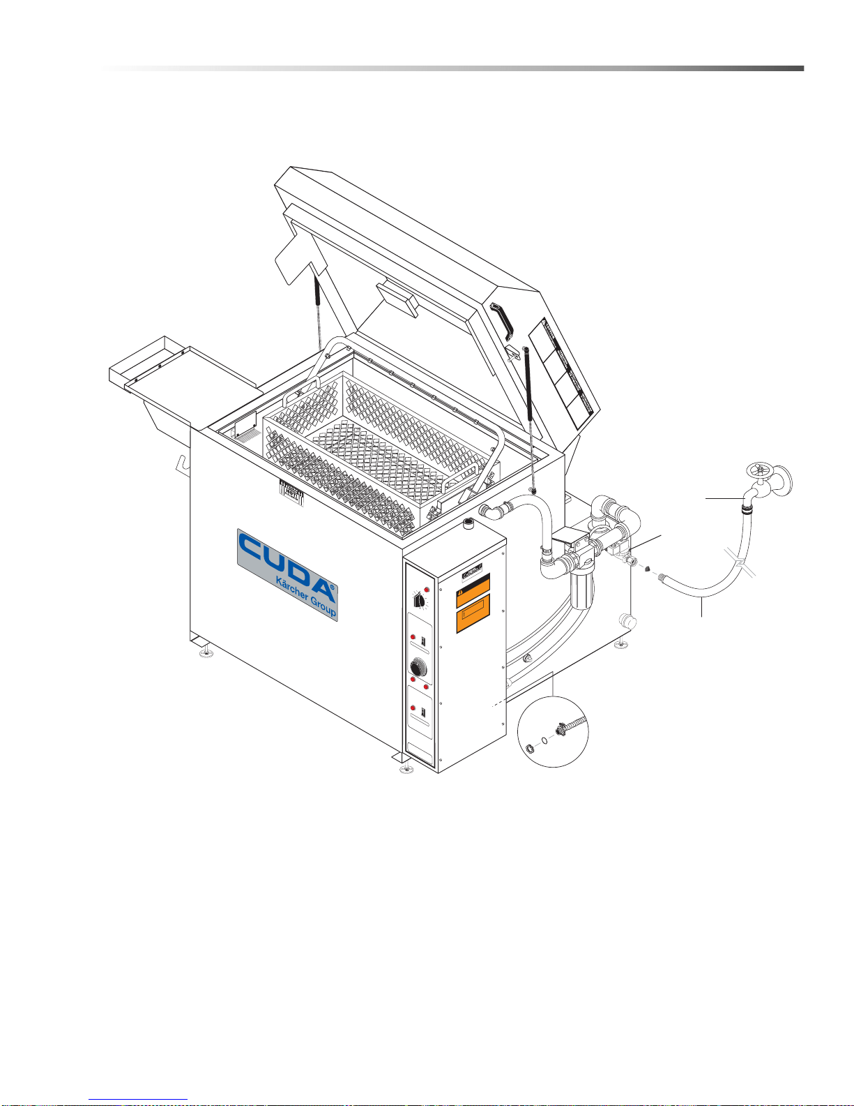
Electrical Connection
Supplied By Qualified
Electrician
Faucet
Water Supply Hose
(not included)
Auto-Fill
Assy.
Operations
INSTALLATION REQUIREMENTS:
Electrical .............................. Refer to Serial Plate located on rear of electrical box
Cabinet Dimensions ........... SJ-15: 48” W x 49” H x 46” D (1 21 .9 2 cm x 12 4 .46 cm x 116.84 cm)
Cuda SJ-15 Series Operator’s Manual 9.801-128.0 - H
11
Page 12

Operations
Installation
1. Location-Locate the SJ-15 parts washer on a level
concrete surface in a room that is well ventilated.
Protect from damaging environments such as
wind, rain, sun and freezing temperatures.
2. Electrical-The SJ-15 is designed for indoor
operation. Refer to the serial plate for proper
voltage and amp requirements for your machine.
All electrical lines must be tested with a voltage
meter for proper voltage before connecting.
NOTE: Correct Rotation of Pump Motor - After
connecting electrical power to parts washer check for
proper rotation of pump motor. Correct rotation is
clockwise looking from the fan end of the motor.
Failure to check rotation and having the motor
operate in a counterclockwise rotation will damage
the pump. Damage will consist of the impeller coming
loose from the motor shaft and damaging the
impeller, shaft seals and pump housing.
CAUTION: All electrical lines must be installed only
by qualified personnel. All installations must be
electrically grounded and conform to all local and
National Electrical codes.
The electrical connection is located on the rear of
the control panel using a 1/2” knock-out. Electrical
conduit must be run all the way to the connection
point in accordance with local codes.
3. Level the SJ-15 by using the leveling pads on the
four corners of the tank.
4. Obtain a detergent designed for parts washer
applications that is suitable for the parts being
cleaned. The detergent must have anti-rust inhibitors added to keep the parts washer from rusting.
Pre-start Checklist
Follow all pre-start procedures
1. Level machine using leveling feet or anchor it to
floor.
2. Verify voltage, then connect the electrical lines to
the machine.
3. Add detergent and water to water tank.
Operating Instructions
1. Voltage light should be illuminated if power supply
is connected. Low water light should be off when
tank water level is correct.
2. Turn the heating element on by setting the 7-day
programmable heater timer. Set the timer by
pulling out trippers on dial to set desired heating
element ON times. Turn dial clockwise until the
time of day is adjacent to time arrow. Heater light
will illuminate when heater element is ON. Allow
about three hours for water to reach operating
temperature. In case of power failure, reset clock
on timer.
3. Set thermostat to the desired temperature.
Suggested operating range is between 130°F to
180°F.
4. Open lid and place the items to be cleaned into the
parts basket. Then close lid. To prevent lifting
injuries, do not attempt lifting basket full of parts.
5. Set the time for the SJ-15 parts washer to operate
by adjusting the wash timer. This is done by
rotating the dial to the desired time set point
(numbers on the face of the timer are in minute
intervals). The wash cycle light will illuminate. This
setting will vary with the degree and type of
cleaning.
5. Fill until low water light goes out.
NOTE: Detergent must be thoroughly mixed
before adding to tank. To ensure detergent mixes
properly and does not foam, make sure machine is
up to operating temperature before adding any
detergent.
12
Cuda SJ-15 Series Operator’s Manual 9.801-128.0 - H
Page 13

Maintenance
Maintenance
CAUTION: Use protective gloves, goggles,
footwear and any other protective clothing requir ed
by law for detergents mixed with the waste stream.
The SJ-15 does not require a lot of maintenance, but it
does require consistent maintenance. The frequ ency of
maintenance varies depending on what is in the water.
General maintenance consists of removal of slu dge
from the bottom of the wash tank and removal of any
floating oil in the wash tank.
WARNING: Shut d own the SJ-15 and allow it to cool
before performing any maintenance. Do not allow
pump to run longer than 5 minutes without water.
Disconnect all hoses to allow water to drain.
Oil Removal
If you have floating oil in the tank that needs to be
removed, shut down the SJ-15 and let the oil floa t to the
top. Remove the chip trays and use oil absorbing
sponges (#21-185) which will absorb only oil. To re-use
the sponge, wring out the oil that is in the sponge into a
container. Oil can be removed automatically when you
have the skimmer.
Sludge Removal
Remove the lower 1-1/2” pipe cap on the side of the
machine allowing all of the water to escape. Use a
small shovel to remove the residual sludge from the
bottom of the tank. Removing the sludge and cleaning
the floor will greatly increase the life of the heating
element.
Detergent and Additives
Manufacturer's detergents are the only detergents
approved for use with our automatic parts washers.
They are specially formulated with rust inhibitors and
anti-foaming agents to optimize performance and
minimize maintenance. The use of any other detergent
during the warranty period will void the warranty.
To monitor the approximate concentration of detergent
in the wash solution, periodically examine the wash
solution in the sump chamber for the following
indicators:
• Rust inside the machine: not enough
detergent
• Excessive foaming: not enough detergent
• Thick, white residue on parts after washing:
too much detergent.
To maintain proper concentration under typical conditions, add detergent each month after cleaning the
sump chamber . Follow recommended detergent qu antities. Use a pH kit to determine the proper amount of
detergent to use. If you need help interpreting test
results, contact customer service.
Rust Inhibitor Additive
Factory detergents protect the entire inside of your
machine against the degenerative effects of water
evaporation. A rust inhibitor additive actually evaporates with the water and continuously coats and
protects metal surfaces, even while your machine is
sitting idle. For more information, contact your dealer or
call customer service.
CAUTION: Disposal of contaminated water must
comply with local and federal EPA regulations.
Spray Arm
The spray nozzles should be checked regularly for
obstruction and cleaned by removing and inserting a
probe. The spray arm nozzle angle on both spray arms
should be mounted in the same direction. The spin pin
o-rings should be replaced annually.
Filters
With the tank empty , clean the suction pump strainer.
Clean when pressure gauge reads a 10 PSI decrease
from start up pressure.
Cuda SJ-15 Series Operator’s Manual 9.801-128.0 - H
13
Page 14
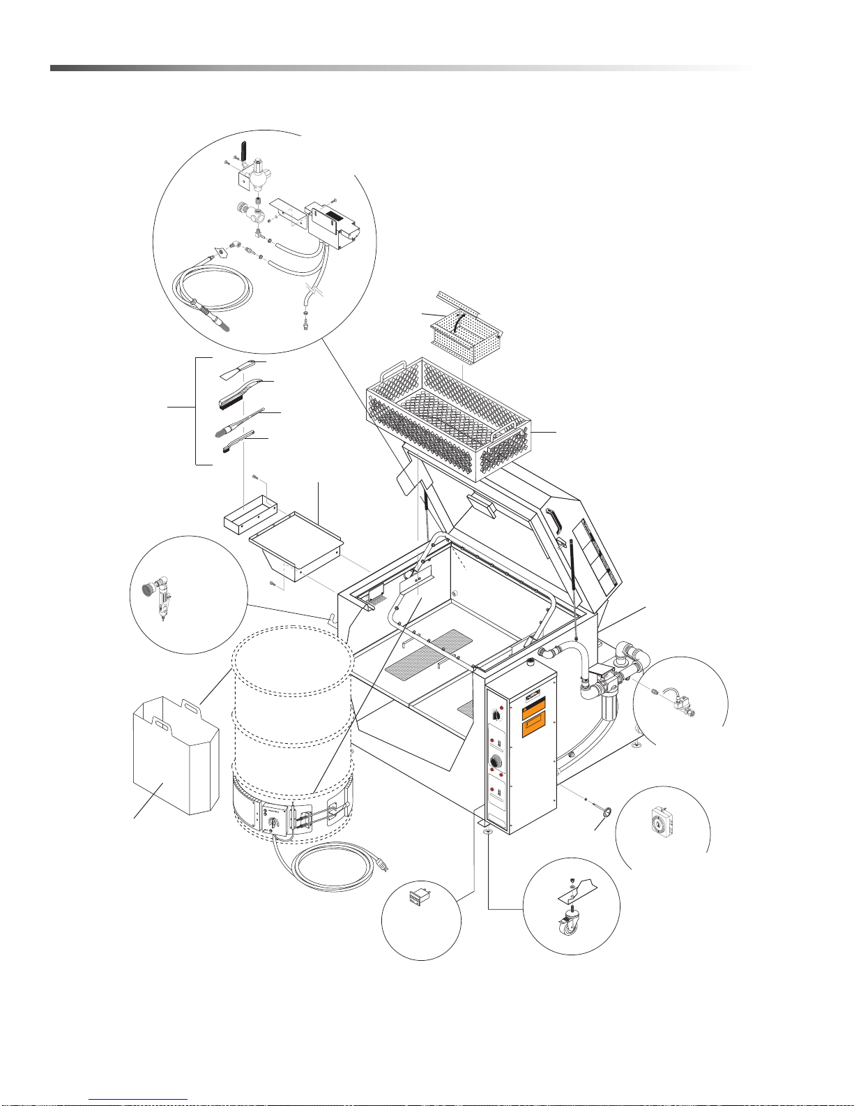
Maintenance
304 Stainless Parts
Basket
8.902-280.0 (SJ-15)
8.719-608.0
8.719-606.0
8.719-351.0
Small Part
Basket
8.731-254.0
Service Tray
8.725-281.0
8.719-348.0
Automatic
Water Fill
8.725-284.0
Hour Meter
9.802-283.0
Waste Water
Drum Evaporator
8.707-034.0
Temperature
Gauge 8.712-156.0
Caster Wheels
8.725-280.0
Timer
(Reversed View)
8.725-283.0
Power Brush
Assy.
8.725-276.0
Oil Decanter
Bucket
8.913-702.0
Mild Steel
Tool Tray
w/Tools
8.725-282.0
Detail Brush Assy
8.725-278.0 Field Installed
Pressure
Gauge
9.804-631.0
Options
WASH CYCLE
CY
C
LO
C
DEa
Y
CL
aa LA
E
DE LA
VA
DO
VA
GE
MINUTE
MI
NU
S
TO
S
H
O
L
D
60
0
50
4
0
TURN
3
0
PAST 10
HEATER
CA
LENTAD
CHA
U
O
FFE
R
-EA
U
ON
OFF 0
N
O
TICE
TIME
/
ATENC
CON
TIMER OV
TROLA
I
O
N
DOR
/ AV
ERID
DE TEM
ANNUL
E
PO FUER
ATI
ON D
E M
A
DE SE
INUTE
RIE
235
2
00
270
0
16
5
30
1
3
0
9
F°
5
1
0
0
2
03
3
F
OF
LO
W
WA
PO
C
T
A
E
PE
AG
R
U
UA
D
'EA
U
VOLTAG
OIL SKIMME
COLECT
OR DE
ECUMEUR
R
ACEI
TE
D'HUI
LE
ON
O
NO
TICE /
T
ATE
NCI
CONT
TIMER
ON /
RO
AVI
L
OVE
ADO
R D
RID
E T
ANNU
E
EM
PO FU
LATI
ER
ON
A D
D
E MINUT
E SE
ERIE
SJ-15
.
A
DE.
WARNING
BLE DISCONECT
COMPLY WITH NEC CO
SIZED LOCKA
10
MACHINE MUST BE CONNECTED TO
PROPERLY
INSTALLATION MUST
2
0
DE.
ES
S CENTIGRA
N USE WIR
DE LEVEL.
WARNING
0 DEGREE
NNECTIO
EAST 9
DE FLOOR OR GRA
AT L
SUPPLY CO
FOR
W GRA
LE FOR
USE BELO
ACCEPTAB
DO NO
1
R
IS
RVIV
O
E
1
FF
0
IME
R
S
R
VI
VO
14
Cuda SJ-15 Series Operator’s Manual 9.801-128.0 - H
Page 15
Maintenance
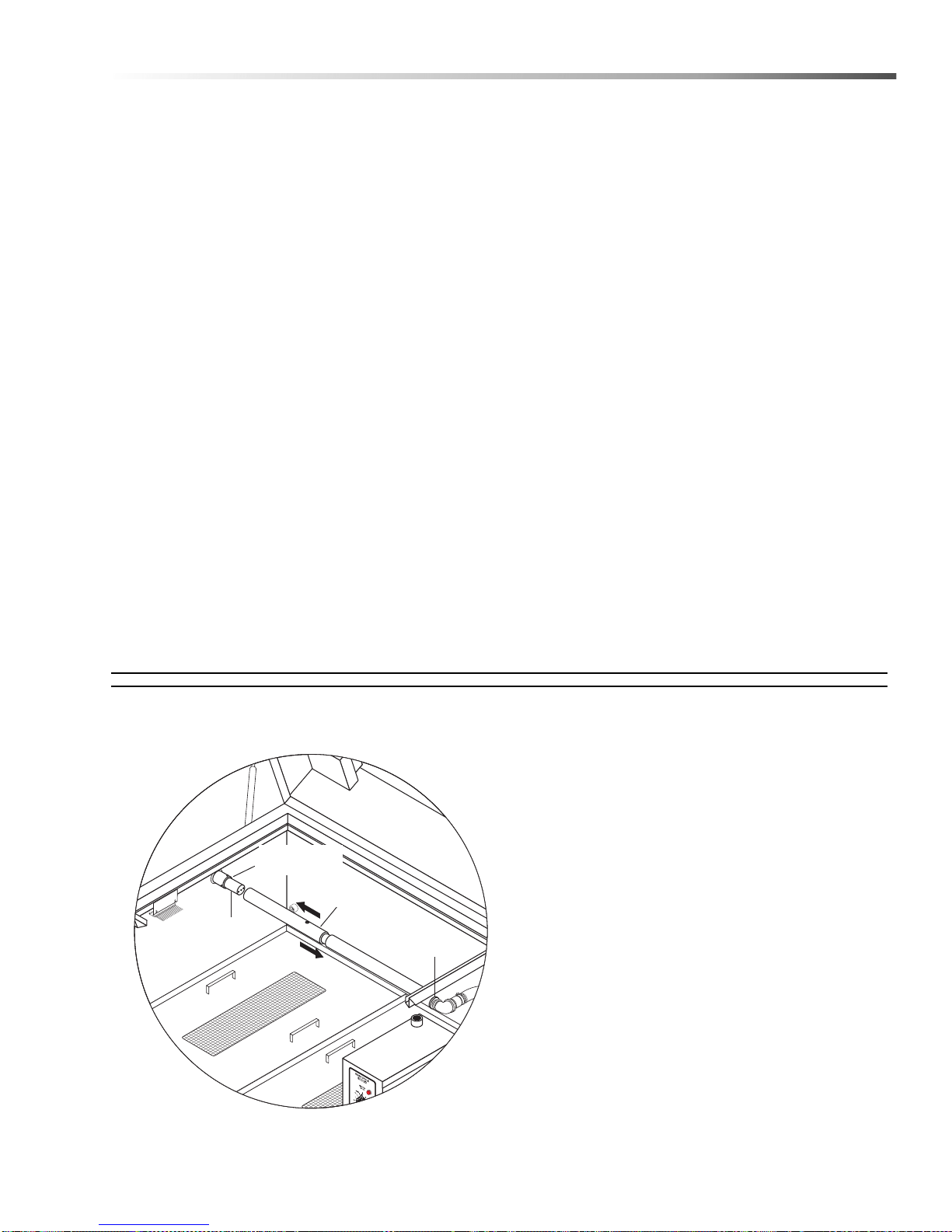
Alignment
Tool
Spin Pin
Spin Pin
Alignment
Allen Screws
Automatic Water Fill
8.725-284.0
The auto fill option consists of a pressure switch electrically connected to a solenoid valve, which is connected
to a fresh water supply line, to add water automatically
to maintain the water level.
Caster Wheel
8.725-280.0
This option allows the SJ-15 to be easily moved from
one location to another.
NOTE: (The electrical power cord is to be provided by
an electrician.)
Small Parts Basket
8.731-254.0
This 8" x 8" x 4" basket comes equipped with a lid to
accommodate small parts that would fall through the
holes of the standard basket.
Service Tray
8.725-281.0
The service tray is installed on the left side to provide a
work area for part inspection, assembly or dry off.
Use hardware from tank to install tray to the side
of the SJ-15.
Tool Basket with Cleaning Tools
8.725-282.0
This tool basket is attached to the service tray or to the
left side of the SJ-15 washer to provide storage for the
cleaning tools which may be needed to provide additional hand cleaning. Can be used for pre-cleaning or
post cleaning of heavy deposits.
Wastewater Drum Evaporator
8.707-034.0
The wash water will eventually have to be removed and
disposal must meet local regulations. If the regulations
require costly disposal, then the wash solution can be
placed in a metal 55 gallon drum (not provided) and the
drum evaporator option can be attached to evaporate
the water and decrease the amount of waste water
being disposed of.
Other Options
8.712-156.0 Temperature Gauge 50° - 500° F
9.804-631.0 Pressure Gauge
9.802-283.0 Hour Meter
8.913-702.0 Oil Drain Container
8.725-276.0 Power Brush Option
Alignment Tool
8.719-616.0
1. Slide the spin pins into the holders and lightly
secure one spin pin by screwing down the
alignment allen screws until the spin pin looks
centered.
2. Place the alignment tool onto the slightly aligned
spin pin and tighten the other spin pin alignment
screws until the alignment tool can easily slide over
the spin pin.
3. Then place alignment tool on spin pin from step 2
and align the other spin pin as described in step 2.
4. The alignment tool should move freely from one
spin pin onto the other spin pin.
Cuda SJ-15 Series Operator’s Manual 9.801-128.0 - H
15
Page 16
Maintenance
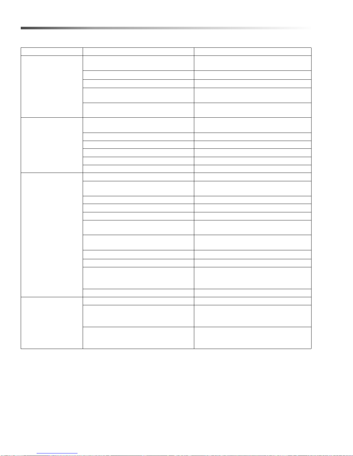
Troubleshooting
PROBLEM POSSIBLE CAUSE SOLUTION
Check with power company; install
heavier wire. See wiring instructions
Reattach heater lead wires.
Check ohms at element
- replace if necessary.
Reset timer.
Allow 15 minutes for motor to cool down.
Overload will automatically reset.
Refer to instructions on wiring. Check and
tighten all wiring.
Check power to coil and replace magnetic
starter/relay.
If voltage under recommended minimum,
check size of wiring from main switch to parts
washer. If OK, contact power company.
Check with power company; install heavier
wiring if wire size is too small. See wiring
instructions.
Check lid safety switch for proper depression. Readjust if needed for proper operation.
HEATER
ELEMENTS
WON'T HEAT
UP/OR HEATS
UP TOO SLOWLY
HEATER
MAGNETIC
STARTER/RELAY
WON'T
ENGAGE
PUMP MOTOR
WILL NOT
RUN
PUMP MOTOR RUNS
HOT
AND OVERLOAD
KICKS OFF
Line voltage too low
Low water level Add water.
Sludge buildup on floor of tank Scrape sludge and remove from tank.
Heater lead wire does not have good
connection
Heater element burned out
Recheck timer for proper setting and
operation
Low water level Add water.
Temperature controller setting too low Increase temperature controller setting.
Fuse blown on transformer Replace fuse.
Low water switch not working Replace or clean.
Starter/relay defective Replace starter/relay.
Wash timer switch is off Be sure switch is on.
Overload switch is tripped
Low water float switch Add water, check float switch.
Wash timer switch is defective Replace switch.
Lid open, not depressing safety switch Close lid.
Wires at motor are loose, disconnected, or
wired incorrectly
Coil on magnetic starter/relay defective
Lid safety switch defective Replace switch.
No power Check incoming power.
Low line voltage
Defective motor Replace motor.
Motor is wired incorrectly Refer to instructions on motor.
Voltage is too low
Pump cycles too frequently
16
Cuda SJ-15 Series Operator’s Manual 9.801-128.0 - H
Page 17
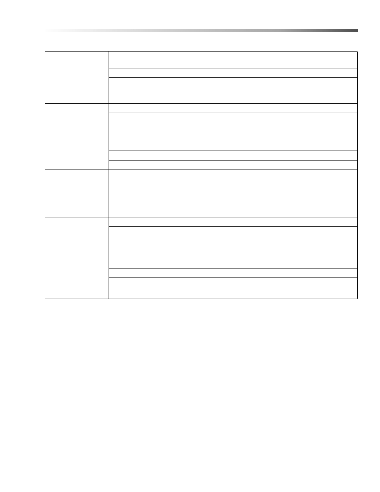
PROBLEM POSSIBLE CAUSE SOLUTION
Air leaks Check all connections on suction line and shaft seal.
PUMP MOTOR
RUNS BUT
NO WATER
IS DELIVERED
SPRA Y ARM WON'T
SPIN
PUMP ST ARTS AND
STOPS
TOO OFTEN
PUMP OPERATING
BUT DELIVERS
LITTLE OR
NO WATER
IMPELLER
VOLTAGE
LIGHT FAILS
TO COME ON
Water level below suction of pump Fill tank with water.
Jet or impeller is plugged Clean jet or impeller, see Maintenance.
Pump outlet strainer plugged Clean or remove sludge from strainer.
Hoses are frozen Thaw out hoses.
Low water temperature Allow water to heat to operating temperature.
Spin pins out of alignment Re-align spin pins.
If voltage under recommended minimum, check size
Low line voltage
Clogged impeller Remove housing, unclog.
Faulty motor overload protector Replace overload.
Low line voltage
Worn or defective pump parts or
plugged impeller
Spray bar nozzles plugged Clean or replace.
Impeller is loose on shaft Tighten impeller set screw.
Impeller rubs housing Realign impeller.
Impeller wobbles or is damaged Replace impeller
Pump motor rotation is in the wrong
direction
No power to parts washer Check circuit breaker supplying power to washe r.
Fuse blown on transformer Replace fuse.
Transformer defective Replace transformer
of wiring from main switch to
parts washer. If OK, contact power company.
If voltage under recommended minimum,
check size of wiring from main switch to
parts washer. If OK, contact power company.
Replace worn parts or entire pump. Clean parts if
required.
Change rotation by following the wiring diagram on
the motor and changing wires to change rotation.
Maintenance
Cuda SJ-15 Series Operator’s Manual 9.801-128.0 - H
17
Page 18

Notes
18
Cuda SJ-15 Series Operator’s Manual 9.801-128.0 - H
Page 19

Parts
Parts
CUDA SJ - 15
1.043-458.0, 1.043-459.0, 1.043-460.0,
1.043-461.0, 1.043-462.0, 1.043-463.0
Cuda SJ-15 Series Operator’s Manual 9.801-128.0 - H
19
Page 20
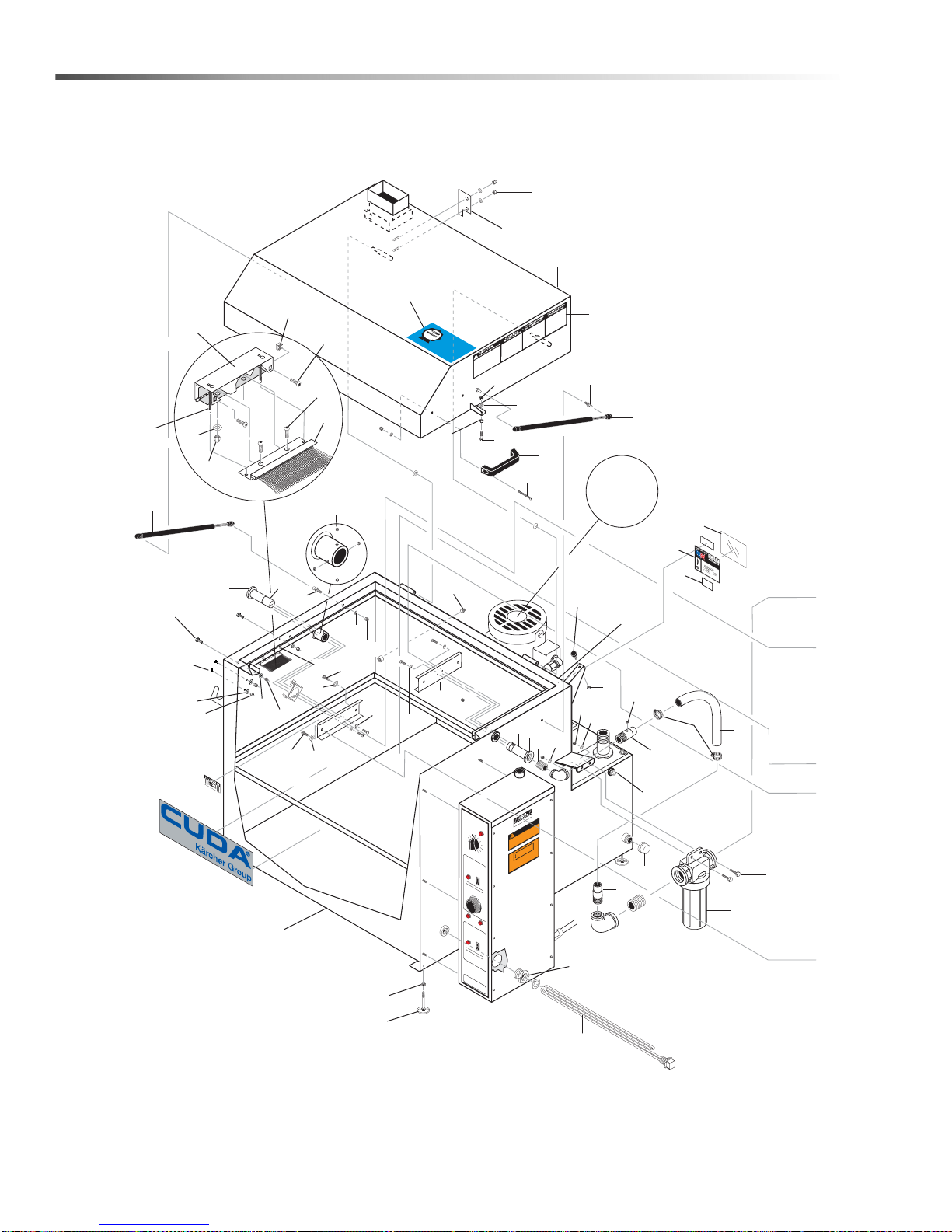
Cuda SJ - 15
7
6
1
9
4
2
76
3
5
For
Detail See
View A-A
16
15
13
14
11
10
43
96
97
98
97
50
13
50
48
41 40
49
47
42
11
41
74
44
42
39
54
64
65
15
56
68
71
49
73
56
66
50
49
66
83
70
50
49
67
69
77
82
85
86
81
Back
of Tank
84
80
46
45
12
88
89
93
92
90
94
45
45
91
91
74
L
I
90
MI
D
AY
T
E
WI
X
L
T
E
T
A
EN
H
B
O
D
C
E
D
R
U
X
S
C
DA
W
T
L
O
A
U
D
1-
RR
S
E
I
V
T
Y
A
E
E
E
N
R
A
U
A
T
G
R
S
Y
EN
E
O
TS
TTEN
F
US
E
LABO
DE
ON
T
E
L
Y
R
RGENT
M
I
W
CU
X
5-
TIO
D
ARRA
G
E
F
D
AL
T
o
A
E
r
L
S
RG
C
ON
AP
T
U
E
NT
O
S
D
h
N
N
P
t
A
(15
T
t
E
p
Y
R
S
A
:
X
/
O
1
T
p
L
/
www
T
I
p
L
O
V
T
c
B
r
END
E
E
o
1-
a
R
(
v
ll
D
1/
S
.
e
c
88
YE
2
)
d
u
O
D
KG
d
8
F
a
-
AR
e
31
W
u
)
t
e
s
P
A
9
r
a.
E
!
T
g
0
R
E
c
e
8
o
R
n
8
m
t
2
s
o
v
r
i
s
i
t
9
.
8
0
7
-51
3
.
0
CH
AUD
!
6
5
0
N
O
C
O
NT
R
0
7
2
0
0
3
LO
W
P
O
CA
PE
CO
N
O
C
O
NT
R
S
W
HO
0
T
I
O
LA
A
NN
3
2
W
U
D'
O
E
TI
O
LA
A
ASH
C
Y
C
L
CY
C
M
L
D
4
0
T
U
H
C
A
C
H
CE
/
A
TI
M
E
D
O
R
UL
A
5
2
0
0
F
°
1
0
-
0
20
3
F
F
O
A
T
ER
A
G
U
A
E
A
U
I
L
L
E
C
T
CU
M
C
E
/
T
I
M
E
D
O
R
NN
UL
A
J-
O
DEa
L
E
D
I
N
M
IN
R
N
EA
LE
N
A
U
T
E
R
O
DE
T
TI
O
N
1
6
5
3
S
KIM
O
R D
EUR
A
T
E
R
OV
D
E
TE
TIO
N
C
a
E
U
U
0
P
A
T
T
FFE
N
V
E
M
DE
1
3
0
N
MP
DE
YC
a
L
LA
V
L
A
A
DO
V
A
G
E
T
E
S
T
O
S
3
0
S
T
1
0
E
R
A
D
O
R
-E
AU
CI
O
N
/
ERI
DE
P
O
FU
E
R
A
M
I
NU
T
E
R
9
5
V
OL
M
E
E
A
CE
IT
D'
H
UILE
C
I
O
N
/ A
E
R
ID
E
O
FU
E
R
A
M
I
N
U
TE
R
1
5
E
NN
WAR
O
AB
C
K
E
C
B
O
T
L
S
O
D
U
E
C
M
IZ
T
E
S
S
N
I
U
Y
H
L
1
M
0
R
N
AC
PE
M
IO
T
A
L
PRO
L
A
T
S
IN
20
R
WA
E
N
N
O
T
S
C
A
Y
E
L
P
L
E
T
D
A
UP
S
A
R
R
R
O
G
F
O
F
E
W
L
O
B
L
A
E
T
B
P
E
E
S
C
U
C
A
O
N
O
D
O
N
1
O
FF
0
T
I
M
ER
A
V
I
S
D
E
S
ER
V
IV
I
E
O
T
A
GE
R
E
O
N
1
O
F
F
0
T
IM
ER
V
IS
D
E
S
ER
V
I
V
O
I
E
.
NING
T
A
.
C
E
O
E
T
D
N
D
O
CO
E
C
T
C
IS
E
D
EC
N
E
H
L
IT
W
Y
L
P
M
G
IN
DE.
N
A
R
S
E
G
.
R
TI
L
E
N
WI
V
E
E
E
C
S
L
S
U
E
E
D
A
ON
I
R
T
G
EGRE
C
D
R
0
O
9
R
O
LO
F
20
Cuda SJ-15 Series Operator’s Manual 9.801-128.0 - H
Page 21
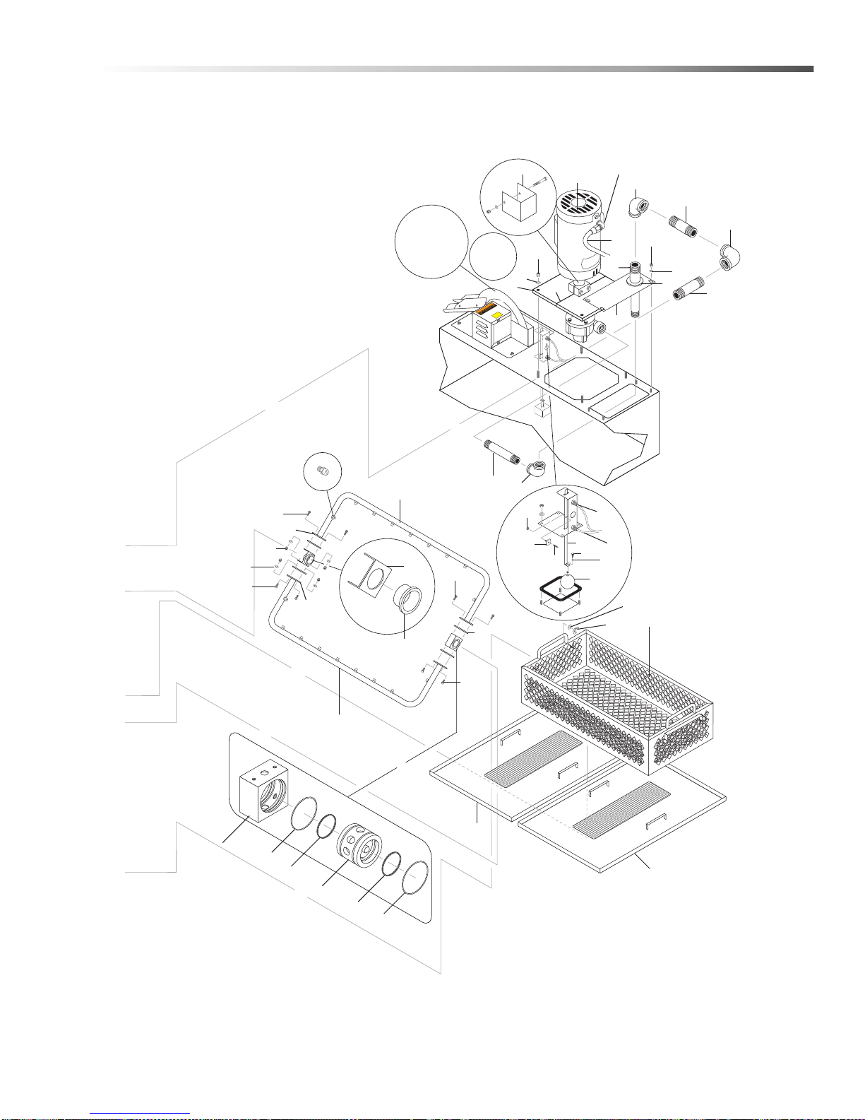
Cuda SJ - 15
19
20
17
20
19
18
38
21
27
22
29
26
28
63
32
23
57
24
87
For Detail
See Oil
Skimmer
Assy.
View
A-A
37
25
24
50
49
53
31
59
24
59
51
30
55
52
55
43
50
36
62
61
60
35
72
43
58
49
33
34
75
29
29
79
78
56
Y
DR
KEEP
21Cuda SJ-15 Series Operator’s Manual 9.801-128.0 - H
Page 22
Cuda SJ - 15
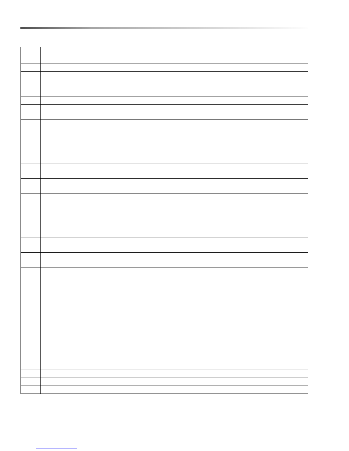
REF PART NO. QTY DESCRIPTION NOTES
1 8.706-519.0 1 BUMPER, RUBBER
2 9.802-262.0 18" HOSE, 1" PUSH-ON
3 8.730-404.0 1 PIPE, 1" BARBED MALE, GALV
4 9.802-028.0 1 ELBOW, 1" X 3/4", 90°, BLACK
5 8.712-996.0 1 ELBOW, 1-1/2" X 1", 90°, REDUCING, BLACK
6 8.706-014.0 1 NIPPLE, 1-1/2" X CLOSE, BLACK
7 8.707-088.0 1 STRAINER, 1-1/2" 30 MESH, SS SCREEN
8 8.911-185.0 1 BRUSH BRACKET
9 8.714-667.0 1 SPIN PIN, W/HOLE
10 8.714-668.0 1 SPIN PIN, NO HOLE, BRASS
11 9.804-367.0 2 O-RING, SPIN PIN BUNA
12 8.913-437.0 1 ASSY,BRUSH,BRAKE
13 8.714-361.0 2 GAS SPRING, STRUT 75#
14 9.804-203.0 2 HANDLE, DOOR
15 9.804-207.0 4 BALL STUD, 5/16"-18UNC 2A STUD
16 8.900-587.0 1 LABEL, WARNING/OPER INSTR.
17 8.707-043.0 1 ROTOR JOINT, GRAPHITOR, GR80
18 8.707-038.0 1 ROTOR HOUSING
19 8.707-412.0 2 O-RING, ROTOR UNION
20 8.707-422.0 2 QUAD RING, ROTOR UNION, VITON
21 8.913-426.0 1 BEARING HOLDER
22 8.714-680.0 23 NOZZLE, 50° FAN, #2, BRASS
23 9.804-399.0 1 GROMMET, 1-1/2" PIPE VINYL
24 8.706-195.0 3 ELBOW, 1-1/2", 90°, BLACK
25 8.919-196.0 2 CHIP TRAY ASSY. W/O EDGE COVER, SJ-15
26 8.715-873.0 1 BEARING, SPRAY ARM
27 8.918-674.0 1 SPRAY ARM, SJ-15
28 8.918-673.0 1 SPRAY ARM W/OFFSET NOZZLES, SJ-15
29 8.707-410.0 4 GASKET, SPRAY ARM, BUNA/NYLON DIAPHRAM4
30 9.804-375.0 1 GASKET, PUMP PLATE
31 9.804-376.0 2 GASKET, PUMP PLATE, CENTER SHELF ADHESIVE
32 8.715-413.0 1 PUMP, 3HP 208-230V 1PH, VERTICAL SEALESS 1.043-458.0
- 8.715-414.0 1 PUMP, 3HP 230/460V 3PH, VERTICAL SEALESS 1.043-459.0
- 8.715-414.0 1 PUMP, 3HP 230/460V 3PH, VERTICAL SEALESS 1.043-460.0
- 8.715-413.0 1 PU MP, 3HP 208-230V 1PH, VERTICAL SEALESS 1.043-462.0
- 8.715-414.0 1 PUMP, 3HP 230/460V 3PH, VERTICAL SEALESS 1.043-463.0
- 8.715-415.0 1 PUMP, 3HP 575V 3PH, VERTICAL SEALESS 1.043-461.0
33 9.804-119.0 1 SWITCH, MAGNETIC REED SENSOR, N.C.
34 9.804-118.0 1 SWITCH, MAGNETIC REED SENSOR, N.O.
35 8.712-132.0 1 FLOAT, 3 -1/2" BALL, SS
36 9.804-120.0 1 MAGNET, REED SENSOR TARGET
37 8.913-461.0 1 BASKET ASSY ., SJ-15
22
Cuda SJ-15 Series Operator’s Manual 9.801-128.0 - H
Page 23
Cuda SJ - 15
REF PART NO. QTY DESCRIPTION NOTES
38 8.919-195.0 1 CHIP TRAY ASSY. W/EDGE COVER, SJ-15
39 8.706-349.0 1 PIPE CAP 1-1/2"
40 8.713-246.0 4 SCREW 5/16 X 1"
41 8.718-987.0 6 WASHER 5/16" RUBBER
42 9.802-776.0 6 NUT, 5/16" ESNA
43 9.802-700.0 6 BOL T, 1/4" X 3/4"
44 8.706-037.0 1 BUSHING, 2' X 1' BLACK PIPE 1.043-458.0 HEATER
- 8.706-037.0 1 BUSHING, 2' X 1' BLACK PIPE 1.043-462.0 HEATER
45 8.718-813.0 4 SCREW 10/32 X 1/2
46 8.714-679.0 4 LEVELING FOOT
47 9.802-703.0 1 BOL T, 1/4" X 1-1/2"
48 9.802-775.0 1 NUT, 1/4"
49 9.802-802.0 17 WASHER 1/4" FLAT
50 9.802-773.0 13 NUT, 1/4" ESNA
51 9.802-779.0 4 NUT, 3/8 ESNA
52 9.802-807.0 4 WASHER, 3/8
53 8.913-741.0 1 PUMP SPACER
- 8.718-611.0 1 BOLT, 1/4" X 3-1/2" NOT SHOWN
- 9.802-802.0 1 WASHER, 1/4” NOT SHOWN
- 9.802-773.0 1 NUT, 1/4" ESNA NOT SHOWN
54 8.913-406.0 2 BASKET SUPPORT
55 8.718-582.0 4 BOL T, 1/4" X 1/2"
56 8.718-978.0 8 WASHER, 1/4" LOCK
57 8.730-381.0 1 NIPPLE, 1-1/2" X 3-3/4", BLACK SCHED 40
58 8.730-383.0 1 NIPPLE, 1-1/2" X 8-1/2", GALV
59 8.730-382.0 2 NIPPLE, 1-1/2" X 5-1/2", GALV
60 8.718-806.0 1 SCREW, 1/4-20 X 1/2" SHCS SS
61 8.718-847.0 1 NUT, KEPS
62 8.731-134.0 1 SCREW, 4-40 X 1/2
63 8.955-155.0 1 FLOAT, ROD, SS
64 9.803-629.0 2 SCREW CLAMP #24
65 9.802-017.0 1 NIPPLE, 3/4" CLOSE, BLACK
66 8.706-328.0 3 PIPE PLUG, 1/4" GALV
67 8.706-350.0 1 PIPE CAP, 1/2" GALV
68 8.913-747.0 1 TANK ASSY , SJ-15
69 8.913-744.0 1 LID ASSY SJ-15
70 8.913-749.0 1 BRACKET HINGE
71 9.801-126.0 1 LABEL, CUDA, 24 X 6"
72 8.718-978.0 1 WASHER, SPLIT RING, SS
73 9.802-701.0 2 BOL T, 1/4" X 1" HEX
74 9.802-724.0 4 BOL T, 3/8" X 1-1/2"
75 8.718-906.0 4 NUT, 3/8" WING
76 8.915-731.0 1 PIPE, 1" BARBED, MALE W/1/4" TAB
23Cuda SJ-15 Series Operator’s Manual 9.801-128.0 - H
Page 24
Cuda SJ - 15
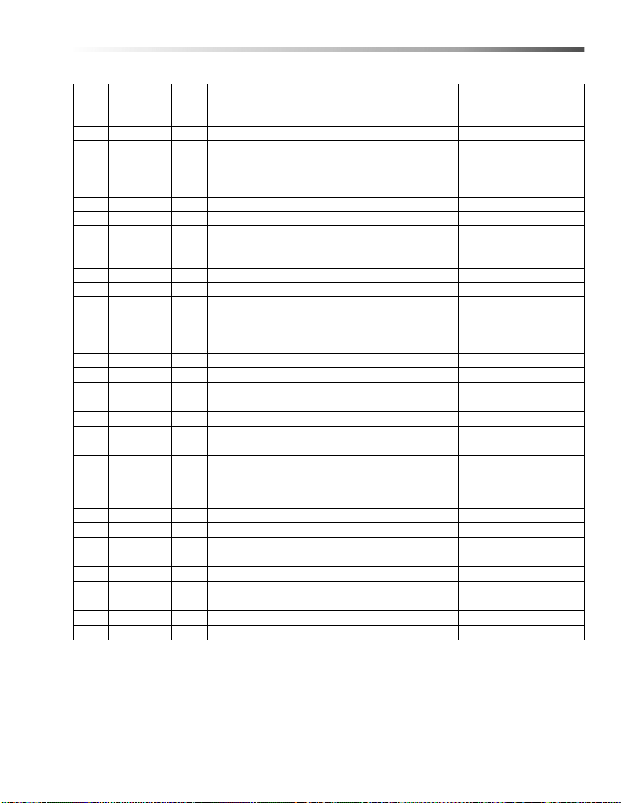
REF PART NO. QTY DESCRIPTION NOTES
77 8.716-646.0 1 HEATING ELEMENT, 6000W 240V,#SGW-2607 V340L 1.043-458.0
- 8.713-253.0 1
- 8.713-254.0 1
- 8.714-491.0 1
- 8.714-581.0 1 HEATING ELEMENT, 6KW 208V 3PH 1.043-463.0
- 8.714-454.0 1
78 8.913-730.0 1 PLUMBING ACCESS COVER
79 9.803-832.0 48" CONDUIT, WATER TIGHT, FLEX 3/4"
- 9.802-448.0 48" CONDUIT, WATER TIGHT, FLEX 1/2" (1.043-461.0 ONLY )
80 9.802-790.0 4 NUT, 1/2" JEX NC
81 9.800-034.0 1 LABEL, CLEAR LEXAN
82 8.725-296.0 2 WASHER, BULLET HINGE, 8MM PIN BRASS
83 9.802-776.0 1 NUT, 5/16" ESNA
HEATING ELEMENT-6KW/230V/3PH 2" NPT,
BRASS, 28"
HEATING ELEMENT, 6KW/480V/3PH 2" NPT,
BRASS, 28”
HEA TING ELEMENT, 6KW/208V/1PH 1" NPT , BRASS,
28" L
HEA TING ELEMENT, 6KW/575V/3PH 2" NPT , BRASS,
15 1/4"
1.043-459.0
1.043-460.0
1.043-462.0
1.043-461.0
24
Cuda SJ-15 Series Operator’s Manual 9.801-128.0 - H
Page 25
Cuda SJ - 15
REF PART NO. QTY DESCRIPTION NOTES
84 8.718-761.0 8 SCREW. SET 5/16-24 X .375 LG SS
85 9.804-361.0 1 LABEL, PARENT NUMBER
86 9.800-013.0 1 LABEL, ASSEMBLED USA
87 9.802-517.0 1 CONNECTOR 1/2" L/T 90° BLACK (1.043-461.0 ONLY)
- 9.803-831.0 1 CONNECTOR 3/4" L/T 90° BLACK (1.043-461.0 ONLY)
88 8.913-434.0 1 ASSY, HOLDER, BRUSH
89 9.802-791.0 2 NUT, CAGE, 10/32" X 16 GA
90 8.719-114.0 2 SPRING, SS, B-BRAKE, SJ-15
91 9.802-808.0 8 WASHER, 3/8” SS
92 8.718-959.0 2 WASHER, #10 FLAT SS
93 9.804-567.0 2 NUT, 10/32" ESNA
94 9.807-513.0 1 LABEL, CUDA APPROVED DETERGENT
95 8.718-978.0 1 WASHER, SPLIT RING, SS
96 9.802-698.0 2 SCREW, 10-32" X 1/2" SLOT PAN, MS
97 8.718-568.0 4 WASHER, 1/4" FLAT RUBBER BACK, SS
98 9.804-567.0 2 NUT, 10/32', ESNA
25Cuda SJ-15 Series Operator’s Manual 9.801-128.0 - H
Page 26
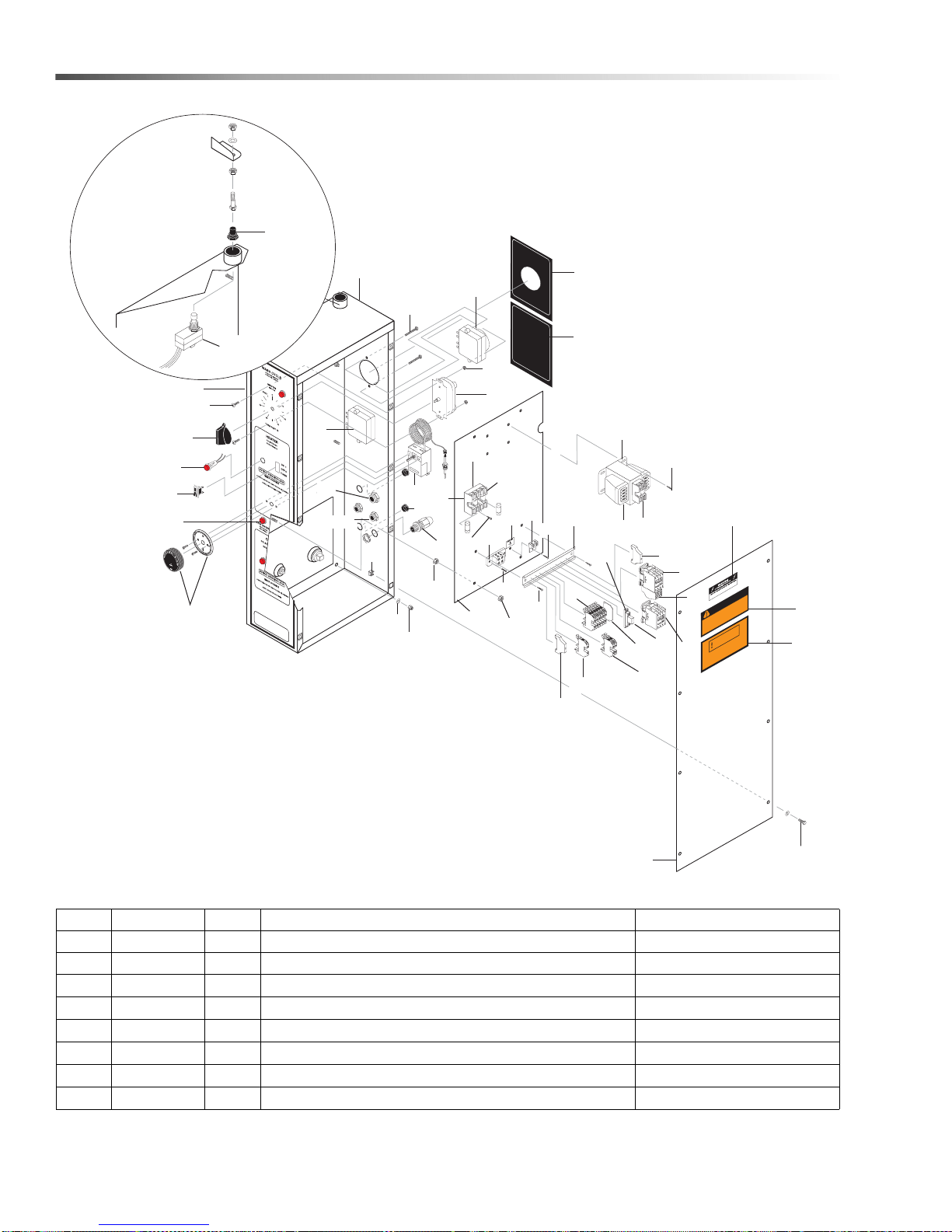
Electrical Panel
22
5
4
1
20
2
6, 30
26
27
16
28
10
12
15
17
3
14
23
25
18
9
8
11
7
29
41
31
52
42
32
36
35
40
34
34
45
39
33
21
26
34
47
56
38
46
13
24
19
45
49
43
44
48
34
37
50
51
53
53
HEATER TIME
7-
D
AY
TIMER
OIL SKIMMER TIMER
24-HOUR
TIMER
R
SJ-15
CHINE MUST BE CONNEC
MA
OPER
PR
INST
CE
AC
DO NO USE BELO
WARNING
SIZED LOCKA
Y
L
TION MUST COMPL
ALLA
ARNING
W
CONNECTION USE
T LEAST 90 DEGREES CENTIGRADE.
FOR SUPPLY
W GRADE FLOOR OR GRADE LEVEL.
ABLE FOR A
PT
TED T
BLE DISCONEC
Y
WITH NEC C
.
T
A
.
O
ODE
WIRES
REF PART NO. QTY DESCRIPTION NOTES
1 9.804-372.0 1 LABEL, WARNING
2 9.800-016.0 1 LABEL, DISCONNECT POWER
3 8.750-864.0 1 CONTACTOR, 3 POLE 30 AMP 1.043-458.0 PUMP
- 8.750-864.0 1 CONTACTOR, 3 POLE 16 AMP (6000W HEATER) 1.043-459.0 PUMP
- 8.750-864.0 1 CONTACTOR, 3 POLE 16 AMP 1.043-460.0 PUMP
- 8.750-864.0 1 CONTACTOR, 3 POLE 16 AMP 1.043-462.0 PUMP
- 8.750-864.0 1 CONTACTOR, 3 POLE 30 AMP 1.043-463.0 PUMP
- 8.750-866.0 1 CONTACTOR, 3 POLE 9 AMP 1.043-461.0 PUMP
26
Cuda SJ-15 Series Operator’s Manual 9.801-128.0 - H
Page 27
Electrical Panel
REF PART NO. QTY DESCRIPTION NOTES
4 9.802-455.0 4 LIGHT, INDICATOR, GREEN 125V
5 9.801-127.0 1 LABEL, SJ-15, CONTROL PANEL
6 9.802-514.0 2 STRAIN RELIEF, 1/2” STRAIGHT
7 8.713-078.0 1 FUSE, 2 AMP FNM-2 1.043-458.0 SECONDARY
- 8.713-078.0 1 FUSE, 2 AMP FNM-2 1.043-459.0 SECONDARY
- 8.713-078.0 1 FUSE, 2 AMP FNM-2 1.043-460.0 SECONDARY
- 8.713-078.0 1 FUSE, 2 AMP FNM-2 1.043-462.0 SECONDARY
- 8.713-078.0 1 FUSE, 2 AMP FNM-2 1.043-463.0 SECONDARY
- 8.713-078.0 1 FUSE, 2 AMP FNM-2 1.043-461.0 SECONDARY
8 8.713-293.0 2 FUSE -CLASS R 20 AMP FRN-R-20 1.043-458.0 PUMP
- 8.713-287.0 3 FUSE -CLASS R 12 AMP 1.043-459.0 PUMP
- 8.713-529.0 3 FUSE, CLASS CC 8 AMP 1.043-460.0 PUMP
- 8.713-539.0 3 FUSE, CLASS CC 7 AMP 1.043-461.0 PUMP
- 8.713-293.0 2 FUSE -CLASS R 20 AMP FRN-R-20 1.043-462.0 PUMP
- 8.713-287.0 3 FUSE -CLASS R 12 AMP 1.043-463.0 PUMP
9 8.713-290.0 1 FUSE BLOCK (H2PR) 2-POLE 1.043-458.0 PUMP
- 8.713-282.0 1 FUSE BLOCK -30A 3POLE 3-POLE 1.043-459.0 PUMP
- 8.713-061.0 1 FUSE BLOCK (C3P) 3-POLE 1.043-460.0 PUMP
- 8.713-061.0 1 FUSE BLOCK (C3P) 3-POLE 1.043-461.0 PUMP
- 8.713-290.0 1 FUSE BLOCK (H2PR) 2-POLE 1.043-462.0 PUMP
- 8.713-282.0 1 FUSE BLOCK -30A 3POLE 3-POLE 1.043-463.0 PUMP
10 8.713-286.0 2 FUSE, CLASS R 2 AMP FNQ-R-2 1.043-458.0 PRIMARY
- 8.713-286.0 2 FUSE, CLASS R 2 AMP FNQ-R-2 1.043-459.0 PRIMARY
- 8.713-080.0 2 FUSE, CLASS R 1 AMP 1.043-460.0 PRIMARY
- 8.713-286.0 2 FUSE, CLASS R 2 AMP FNQ-R-2 1.043-462.0 PRIMARY
- 8.713-286.0 2 FUSE, CLASS R 2 AMP FNQ-R-2 1.043-463.0 PRIMARY
- 8.713-080.0 2 FUSE, CLASS R 1 AMP 1.043-461.0 PRIMARY
11 8.713-291.0 2 FUSE -30 AMP 1.043-458.0 HTR
- 8.713-288.0 3 FUSE -20 AMP NON-20 1.043-459.0 HTR
- 8.713-066.0 3 FUSE -CLASS CC 10 AMP 1.043-460.0 HTR
- 8.713-529.0 3 FUSE, Class CC 8 AMP 1.043-461.0 HTR
- 8.714-451.0 2 FUSE -35 AMP 1.043-462.0 HTR
- 8.713-369.0 3 FUSE -25 AMP 1.043-463.0 HTR
12 8.713-086.0 1 GROUND, LUG 2, HOLE
13 9.804-140.0 1 DECAL, WARNING GRADE LEVEL
27Cuda SJ-15 Series Operator’s Manual 9.801-128.0 - H
Page 28
Electrical Panel
REF PART NO. QTY DESCRIPTION NOTES
14 8.750-875.0 1 OVERLOAD, 14.5-18 AMP 1.043-458.0 PUMP
- 8.750-874.0 1 OVERLOAD, 8.0-12 AMP 1.043-459.0 PUMP
- 8.750-874.0 1 OVERLOAD, 8.0-12 AMP 1.043-460.0 PUMP
- 8.750-875.0 1 OVERLOAD, 14.5-18 AMP 1.043-462.0 PUMP
- 8.750-874.0 1 OVERLOAD, 8.0-12 AMP 1.043-463.0 PUMP
- 8.750-871.0 1 OVERLOAD, 2.5-4.1 AMP 1.043-461.0 PUMP
15 8.714-164.0 1 TERMINAL BLOCK, 2 POSITION
- 8.714-512.0 1 TERMINAL BLOCK, 3 POSITION
- 8.714-512.0 1 TERMINAL BLOCK, 3 POSITION
- 8.714-164.0 1 TERMINAL BLOCK, 2 POSITION
- 8.714-512.0 1 TERMINAL BLOCK, 3 POSITION
- 8.714-512.0 1 TERMINAL BLOCK, 3 POSITION
16 8.716-875.0 1 TRANSFORMER, 200VA 230-460V/115V
- 8.716-875.0 1 TRANSFORMER, 200VA 230-460V/115V
- 8.716-875.0 1 TRANSFORMER, 200VA 230-460V/115V
- 8.716-895.0 1 TRANSFORMER, 200VA 208-230-460V/115V
- 8.716-895.0 1 TRANSFORMER, 200VA 208-230-460V/115V
- 8.713-907.0 1 TRANSFORMER, 200VA 575V/115V
17 9.802-457.0 7.25" RAIL, DIN, ALUMINUM
18 8.753-368.0 1 RELAY, BASE
19 8.753-367.0 1 RELAY, SPDT
20 9.804-510.0 1 SWITCH, 15 AMP
21 8.713-105.0 1 SWITCH BOOT, THREADED
22 8.716-052.0 2 SWITCH, CURVETTE
23 8.716-398.0 6 TERMINAL BLOCK, BLUE
24 8.716-599.0 1 TERMINAL BLOCK, GREEN
25 8.716-396.0 2 TERMINAL BLOCK, GREY
26 9.804-295.0 1 THERMOSTAT
27 8.712-832.0 1 TIMER, 60 MIN, SPRING WOUND
28 8.716-254.0 1 TIMER, 7-DAY PIN, 120V 20 AMP
29 8.716-253.0 1 TIMER, SKIMMER, 24 HR (OPTION)
30 9.802-525.0 2 LOCKNUT 1/2"
1.043-458.0 INCOMING
PWR
1.043-459.0 INCOMING
PWR
1.043-460.0 INCOMING
PWR
1.043-462.0 INCOMING
PWR
1.043-463.0 INCOMING
PWR
1.043-461.0 INCOMING
PWR
1.043-458.0 CONTROL
CIRCUIT
1.043-459.0 CONTROL
CIRCUIT
1.043-460.0 CONTROL
CIRCUIT
1.043-462.0 CONTROL
CIRCUIT
1.043-463.0 CONTROL
CIRCUIT
1.043-461.0 CONTROL
CIRCUIT
28
Cuda SJ-15 Series Operator’s Manual 9.801-128.0 - H
Page 29
Electrical Panel
REF PART NO. QTY DESCRIPTION NOTES
31 8.716-547.0 1 CONNECTOR 1/2" (1.043-461.0 ONLY)
32 9.802-105.0 2 PLUG, 7/8"
33 8.716-400.0 1 END COVER, BLUE
34 8.718-936.0 11 SCREW, #8 X 1/2
35 8.718-937.0 2 SCREW, #8 X 3/4
36 9.802-793.0 10 CAGE NUT, 1/4"
37 8.718-582.0 8 BOLT 1/4" X 1/2"
38 8.718-980.0 5 WASHER, 5/16" FLAT
39 8.913-731.0 1 ELECTRICAL BOX COVER
40 8.913-735.0 1 ELECTRICAL PANEL
41 8.913-748.0 1 CONTROL BOX
42 8.718-755.0 2 SCREW, 8/32 X 1-1/2"
43 8.900-593.0 1 LABEL, HEATER
44 8.900-592.0 1 LABEL, OIL SKIMMER
45 9.804-595.0 2 END BRACKET
46 9.802-776.0 5 NUT, 5/16 ESNA
47 8.718-733.0 2 SCREW, 6/32 X 5/8
48 9.802-784.0 2 NUT, 6/32 KEPS
49 9.800-040.0 1 LABEL, GROUND
50 8.750-863.0 1 CONTACTOR, IEC, 3 POLE, 30A, NO AUX 1.043-458.0 HTR
- 8.750-863.0 1 CONT ACTOR, IEC, 3 POLE, 30A, NO AUX 1.043-459.0 HTR
- 8.750-864.0 1 CONT ACTOR, IEC, 3 POLE, 16A, NO AUX 1.043-460.0 HTR
- 8.750-866.0 1 CONTACTOR, IEC, 3 POLE, 9A, NO AUX 1.043-461.0 HTR
- 8.750-863.0 1 CONT ACTOR, IEC, 3 POLE, 30A, NO AUX 1.043-462.0 HTR
- 8.750-863.0 1 CONT ACTOR, IEC, 3 POLE, 30A, NO AUX 1.043-463.0 HTR
51 8.716-408.0 1 LIGHT, INDICATOR AMBER 125V
(1.043-458.0,1.043-459.0,
52 8.716-549.0 1 CONNECTOR 3/4" L/T STRAIGHT, BLACK
53 9.802-778.0 8 NUT, 5/16" WHIZ LOC
54 8.755-016.0 2 TERMINAL BLOCK JUMPER, 2 POLE NOT SHOWN
55 8.713-290.0 1 FUSE BLOCK (H2PR) 2-POLE 1.043-458.0 HTR
- 8.713-282.0 1 FUSE BLOCK -30A 3POLE 3-POLE 1.043-459.0 HTR
- 8.713-061.0 1 FUSE BLOCK (C3P) 3-POLE 1.043-460.0 HTR
- 8.713-061.0 1 FUSE BLOCK (C3P) 3-POLE 1.043-461.0 HTR
- 8.714-132.0 1 FUSE BLOCK -60A 2-POLE 1.043-462.0 HTR
- 8.713-282.0 1 FUSE BLOCK -30A 3POLE 3-POLE 1.043-463.0 HTR
56 8.756-586.0 KNOB, TIMER, SPRING WOUND
1.043-460.0, 1.043-462.0,
1.043-463.0)
29Cuda SJ-15 Series Operator’s Manual 9.801-128.0 - H
Page 30
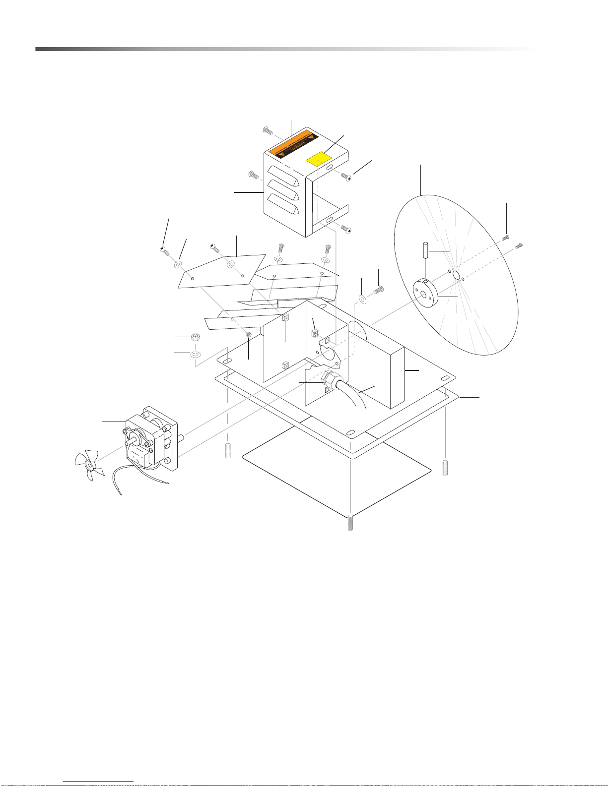
Oil Skimmer
2
1
4
5
6
7
10
9
8
15
16
1
13,14
20
11
18
21
3
17
17
1
12
19
DRY
KEEP
30
Cuda SJ-15 Series Operator’s Manual 9.801-128.0 - H
Page 31
Oil Skimmer
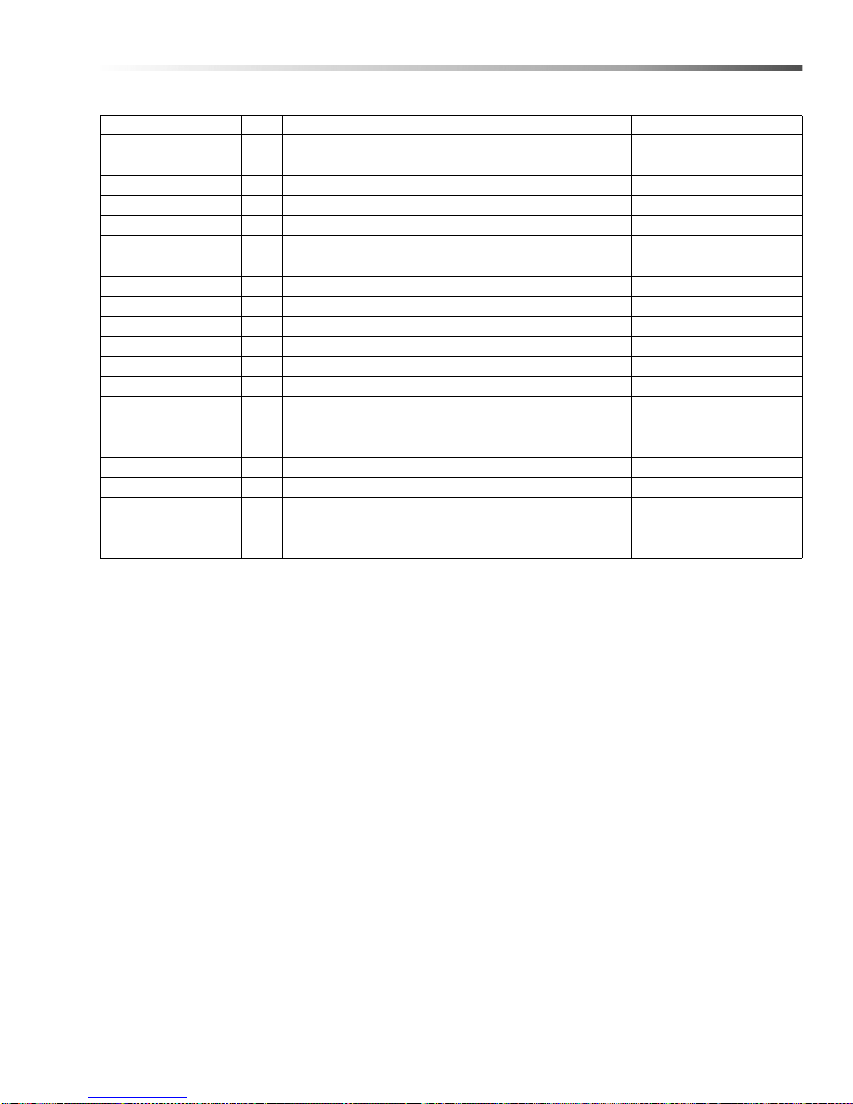
REF PART NO. QTY DESCRIPTION NOTES
1 8.718-810.0 11 SCREW, 10/32" X 1/2", WHIZ LOC FLANGE
2 8.913-733.0 1 COVER, MOTOR, DISC SKIMMER
3 9.802-698.0 1 WASHER #10 FLAT ZINC PLT
4 9.804-102.0 4 BLADE, WIPER, DISC SKIMMER SS
5 9.802-773.0 2 NUT, 1/4" ESNA
6 8.904-676.0 4 MOTOR, DISC SKIMMER
7 8.719-987.0 1 HUB, DISC MOUNT, DISC SKIMMER
8 8.719-068.0 1 PIN, ROLL 1/8" X 1" STEEL
9 8.918-672.0 1 DISC, DISC SKIMMER SS
10 9.804-564.0 2 SCREW, 6-22 X 12
11 9.804-567.0 4 NUT, 10/32 ESNA
12 9.802-802.0 4 WASHER, 1/4" FLAT
13 9.802-514.0 1 STRAIN RELIEF
14 9.802-525.0 1 LOCKNUT 1/2"
15 8.913-751.0 1 OIL SKIMMER, LARGE
16 8.718-568.0 3 WASHER, 1/4" SEALING
17 9.802-791.0 4 NUT CAGE, 10/32
18 9.804-374.0 1 DECA L, KEEP DRY
19 9.800-016.0 1 LABEL, DISCONNECTED POWER
20 9.802-423.0 84" CORD 16/3
21 9.804-621.0 1 GASKET, SKIMMER
31Cuda SJ-15 Series Operator’s Manual 9.801-128.0 - H
Page 32
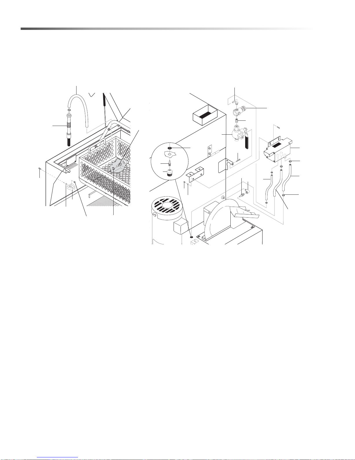
Detail Brush
13
4
23
11
9
15
17
5
14
3
19
6
18
14
12
16
8
1
2
22
17
21
16
20
7
10
32
Cuda SJ-15 Series Operator’s Manual 9.801-128.0 - H
Page 33
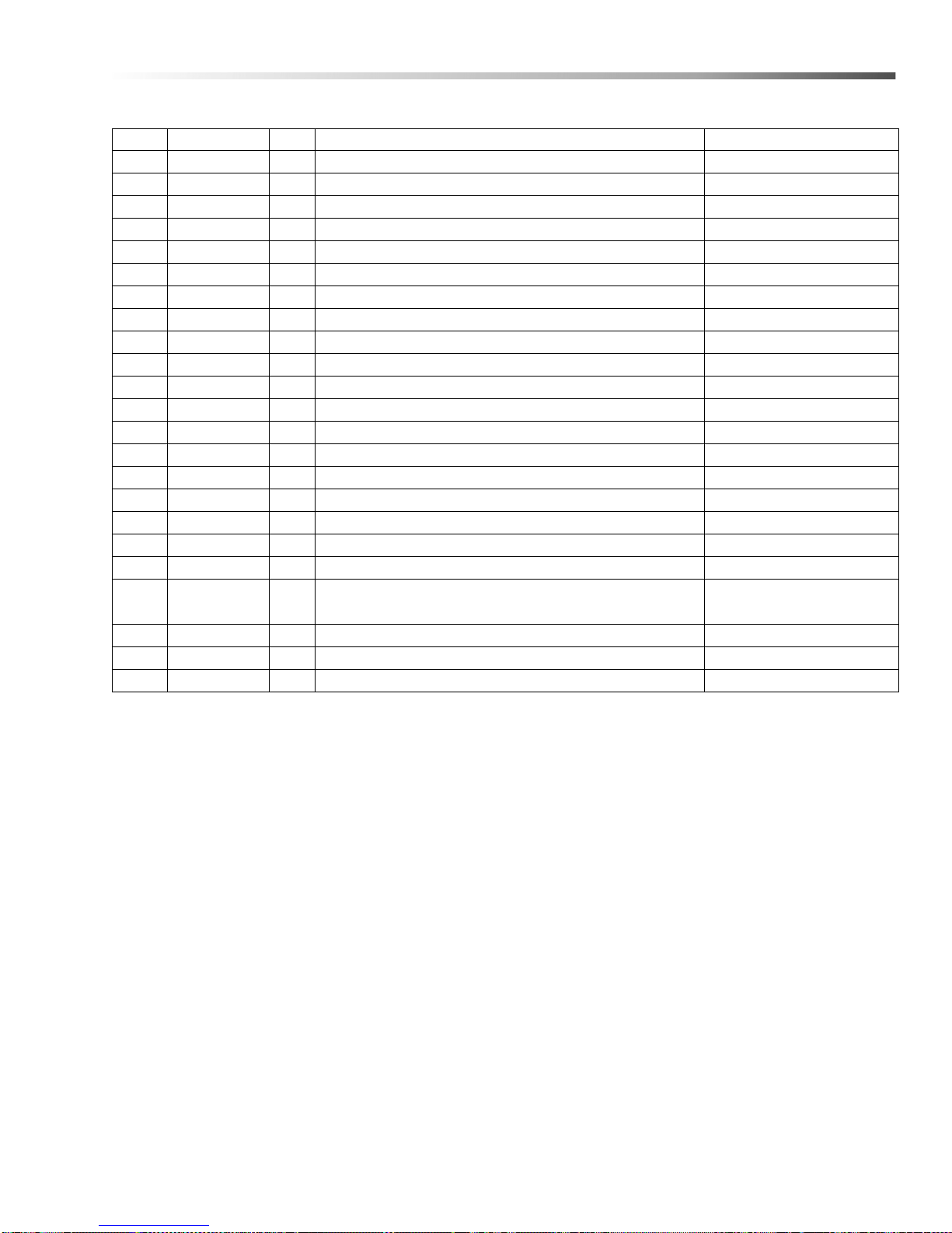
Detail Brush
REF PART NO. QTY DESCRIPTION NOTES
1 8.712-778.0 1 PUMP , AIR DIAPHRAGM
2 8.709-117.0 3 CLAMP, HOSE, UNI .62-.75 ST
3 8.712-810.0 1 REGULATOR, AIR 1/4" NPT
4 9.804-091.0 1 BRUSH POLYFLOW (FLO-THRU)
5 8.712-815.0 1 CLIP, DETAIL BRUSH
6 8.712-838.0 1 PIPE, BALL VALVE 1/4" 3-WAY
7 9.802-254.0 17" HOSE, 1/4", PUSH-ON, FUEL LINE/FT
8 8.706-161.0 1 ELBOW, 1/4", STREET, 90° GALV
9 9.802-698.0 5 SCREW, 10-32" X 1/2" SLOT PAN, MS, SS
10 8.711-785.0 22" HOSE, 3/8" PUSH ON, /FT
11 9.804-567.0 5 NUT, 10/32", ESNA
12 8.718-959.0 2 WASHER, #10 FLAT S/S
13 8.714-007.0 60" HOSE -1/4" ID X 7/16" OD BUNA TUBING 60 DURO
14 9.802-143.0 1 HOSE BARB, 1/4" BARB X 1/4" PIPE, 90°
15 9.802-138.0 1 HOSE BARB, 1/4" BARB X 1/4" ML PIPE, BRASS
16 8.705-104.0 2 HOSE BARB, 3/8" BARB X 1/4" ML PIPE
17 6.390-126.0 4 CLAMP, HOSE, .46-.54 ST
18 8.714-255.0 2 SCREW, 10-24 X 1/4"SS MS PHIL
19 8.705-204.0 1 NIPPLE, 1/4" CLOSE
20 8.712-808.0 1
21 9.802-103.0 1 BUSHING, SNAP, 5/8"
22 8.711-785.0 16" HOSE, 3/8" PUSH-ON, /FT
23 8.718-568.0 1 WASHER, 1/4" FLAT SS SEALING RUB
FILTER, INLET
(MESH BALL 1/4" NPT 20 X 20 MESH) DETAIL PUMP
33Cuda SJ-15 Series Operator’s Manual 9.801-128.0 - H
Page 34

9.801-128.0 • Printed in U.S.A.
 Loading...