

Page 1
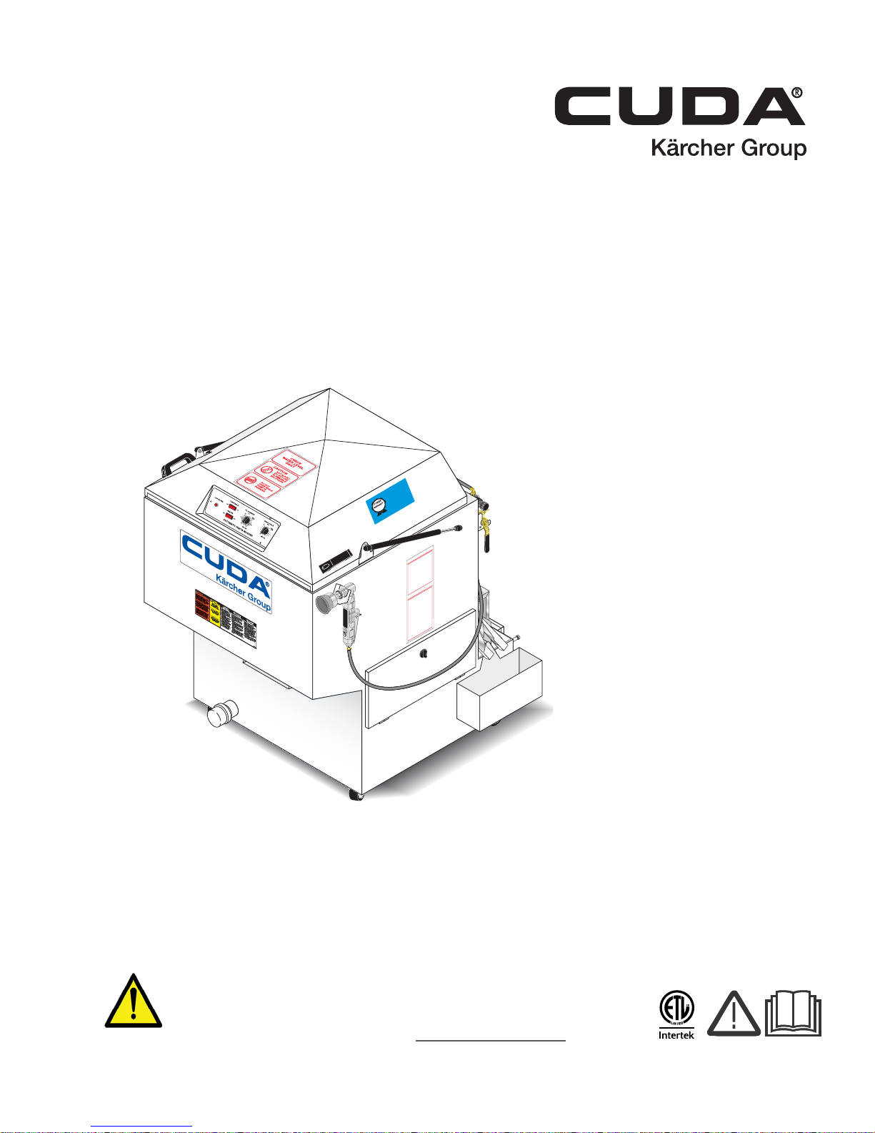
H2O-2412 Series
OPERATING INST
RUCTIONS
MAINTENANCE INSTR
UCTIONS
A
T
TENTIO
N
USE ON
L
Y CUDA
APP
R
O
VED
DETERGENTS
TO
EXTEND
LABOR WARRANT
Y
T
O 1-YEAR!
MIX DETERGENTS
1 LB (1/2
KG) PER
5-GAL
LONS (15 L
ITERS) OF
W
A
TE
R
For C
U
D
A Ap
p
r
o
ved Dete
r
g
ents visit
http://ww
w
.cudausa.com or
call 888-319-0882
9.807-51
3.0
90-D
A
Y
LABOR
W
A
RRANT
Y
EXTEN
DS TO 1-YEAR
WITH EXCLUSIVE
USE OF
CUDA DETERGENT
S
L
IM
IT
E
D
Operator’ s Manual
Automatic Parts Washer
Top-Load
MODELS: 1.043-356.0
1.043-379.0
1.043-357.0
1.043-536.0
1.043-537.0
1.043-538.0
WARNING:
This product can expose you to chemicals which are known to the
State of California to cause cancer and birth defects or other
reproductive harm.
For more information about this regulation: www.P65Warnings.ca.gov
For the Cuda Dealer nearest you,
consult our web page at
www.CudaUSA.com
8.914-384.0-V 01/05/18
Page 2
Machine Data Label
2 Cuda 2412 Operator’s Manual 8.914-384.0 - V
Page 3

Table of Contents
Machine Data Label. . . . . . . . . . . . . . . . . . . . . . . . . .2
Table of Contents . . . . . . . . . . . . . . . . . . . . . . . . . . .3
How To Use This Manual . . . . . . . . . . . . . . . . . . . . .4
Safety
Introduction & Safety Information . . . . . . . . . . . . . . .5
General Safety Information. . . . . . . . . . . . . . . . . . . .6
Operations
Component Identification - Front View . . . . . . . . . . .8
Component Identification - Rear View . . . . . . . . . . .9
Installation . . . . . . . . . . . . . . . . . . . . . . . . . . . . . . . .10
Before You Begin . . . . . . . . . . . . . . . . . . . . . . . . . .10
Step 1: Make Electrical Connections . . . . . . . . . . .10
Step 2: Connect A Compressed-air Line And
Accessories (Optional) . . . . . . . . . . . . . . . . . . . .10
Step 3: Connect A Water Line . . . . . . . . . . . . . . . .10
Step 4: Fill The Machine With Water And Add
Detergent . . . . . . . . . . . . . . . . . . . . . . . . . . . . . .11
Operations . . . . . . . . . . . . . . . . . . . . . . . . . . . . . . . .12
Main Operating Components . . . . . . . . . . . . . . . . .12
Control Panel . . . . . . . . . . . . . . . . . . . . . . . . . . . . .12
Low Water Indicator . . . . . . . . . . . . . . . . . . . . . . . .12
Turntable Switch . . . . . . . . . . . . . . . . . . . . . . . . . . .12
Heater Control. . . . . . . . . . . . . . . . . . . . . . . . . . . . .12
Wash Cycle Control . . . . . . . . . . . . . . . . . . . . . . . .12
Thermostat . . . . . . . . . . . . . . . . . . . . . . . . . . . . . . .12
Turntable Assembly . . . . . . . . . . . . . . . . . . . . . . . .13
Using the Power Brush . . . . . . . . . . . . . . . . . . . . . .14
Adjusting the Flow of Cleaning Solution . . . . . . . . .14
Water Level. . . . . . . . . . . . . . . . . . . . . . . . . . . . . . .15
Low Water Shut-off System . . . . . . . . . . . . . . . . . .15
Detergents And Additives . . . . . . . . . . . . . . . . . . . .16
Preparing The Machine For Use. . . . . . . . . . . . . . .16
Using the Oil Skimmer System . . . . . . . . . . . . . . . .17
Shutting Down The Machine. . . . . . . . . . . . . . . . . .18
Troubleshooting the Electrical System . . . . . . . . . .24
Troubleshooting the Electrical Panel . . . . . . . . . . .24
Testing Individual Components. . . . . . . . . . . . . . . .25
Parts
Oil Skimmer . . . . . . . . . . . . . . . . . . . . . . . . . . . . . 30
115V Electrical Panel . . . . . . . . . . . . . . . . . . . . . . 32
208V, 230V Electrical Panel . . . . . . . . . . . . . . . . . 36
Cuda 2412 Front. . . . . . . . . . . . . . . . . . . . . . . . . . 40
Cuda 2412 Rear . . . . . . . . . . . . . . . . . . . . . . . . . . 44
Auto Fill, Detail Brush & Power Brush Options. . . 46
Filter Option 8.725-269.0 . . . . . . . . . . . . . . . . . . . 50
Maintenance
Maintaining The Machine . . . . . . . . . . . . . . . . . . . .19
Daily Maintenance . . . . . . . . . . . . . . . . . . . . . . . . .19
Weekly Maintenance. . . . . . . . . . . . . . . . . . . . . . . .19
Monthly Maintenance . . . . . . . . . . . . . . . . . . . . . . .19
Cleaning out the Sump . . . . . . . . . . . . . . . . . . . . . .20
Repairing The Machine. . . . . . . . . . . . . . . . . . . . . .20
Heating Element . . . . . . . . . . . . . . . . . . . . . . . . . . .20
Thermostat . . . . . . . . . . . . . . . . . . . . . . . . . . . . . . .21
Timers and Switches. . . . . . . . . . . . . . . . . . . . . . . .21
Cleaning and Aligning the Spray Nozzles. . . . . . . .22
Torque Limiter. . . . . . . . . . . . . . . . . . . . . . . . . . . . .22
Turntable Motor. . . . . . . . . . . . . . . . . . . . . . . . . . . .22
Troubleshooting . . . . . . . . . . . . . . . . . . . . . . . . . . .24
Cuda 2412 Operator’s Manual 8.914-384.0 - V
3
Page 4

How To Use This Manual
Model:
Date of Purchase:
Serial Number:
Dealer:
Address:
Phone Number:
Sales Representative:
This manual contains the following sections:
• How to Use This Manual
•Safety
• Operations
• Maintenance
• Parts List
The HOW TO USE THIS MANUAL section will tell you
how to find important information for ordering correct
repair parts.
Parts may be ordered from authorized dealers. When
placing an order for parts, the machine model and
machine serial number are important. Refer to the
MACHINE DATA box which is filled out during the
installation of your machine. The MACHINE DATA box
is located on the inside of the front cover of this manual.
The model and serial number of your machine is
located on the back of the machine.
The SAFETY section contains important information
regarding hazardous or unsafe practices of the
machine. Levels of hazards are identified that could
result in product damage, personal injury, or severe
injury resulting in death.
The OPERAT IONS section is to familiarize the operator
with the operation and function of the machine.
The MAINTENANCE section contains preventive maintenance to keep the machine and its components in
good working condition. They are listed in this general
order:
• Maintaining The Machine
• Daily Maintenance
• Weekly Maintenance
• Monthly Maintenance
• Cleaning And Aligning The Spray Nozzles
• Cleaning Out The Slump
• Repairing The Machine
• Heating Element
•Thermostat
• Timers and Switches on The Control Panel
• Torque Limiter
• Turntable Motor
• Using The Oil Skimmer System
• Troubleshooting
The PARTS LIST section contains assembled parts
illustrations and corresponding parts list. The parts lists
include a number of columns of information:
4
Cuda 2412 Operator’s Manual 8.914-384.0 - V
• REF – column refers to the reference number
on the parts illustration.
• PART NO. – column lists the part number for
the part.
• QTY – column lists the quantity of the part used
in that area of the machine.
• DESCRIPTION – column is a brief description
of the part.
• NOTES – column for information not noted by
the other columns.
NOTE: If a service or option kit is installed on your
machine, be sure to keep the KIT INSTRUCTIONS
which came with the kit. It contains replacement parts
numbers needed for ordering future parts.
NOTE: The manual part number is located on the
lower right corner of the front cover.
Page 5

Introduction & Safety Information
This manual is intended as a guide for safely installing,
operating and maintaining your Automatic Parts
Washer.
We reserve the right to make changes at any time
without incurring any obligation.
Owner/User Responsibility:
The owner and/or user must have an understanding of
the manufacturer’s operating instructions and warnings
before using this machine. Warning information should
be emphasized and understood. If the operator is not
fluent in English, the manufacturer’s instructions and
warnings shall be read to and discussed with the
operator in the operator’s native language by the
purchaser/owner, making sure that the operator
comprehends its contents.
Owner and/or user must study and maintain for future
reference the manufacturers’ instructions.
Safety
Save these Instructions
This manual should be considered a permanent par t of
the machine and should remain with it if machine is
resold.
When ordering parts, please specify model and serial
number . Use only identical replacement parts.
This machine is to be used only by trained
operators.
Cuda 2412 Operator’s Manual 8.914-384.0 - V
5
Page 6
Safety
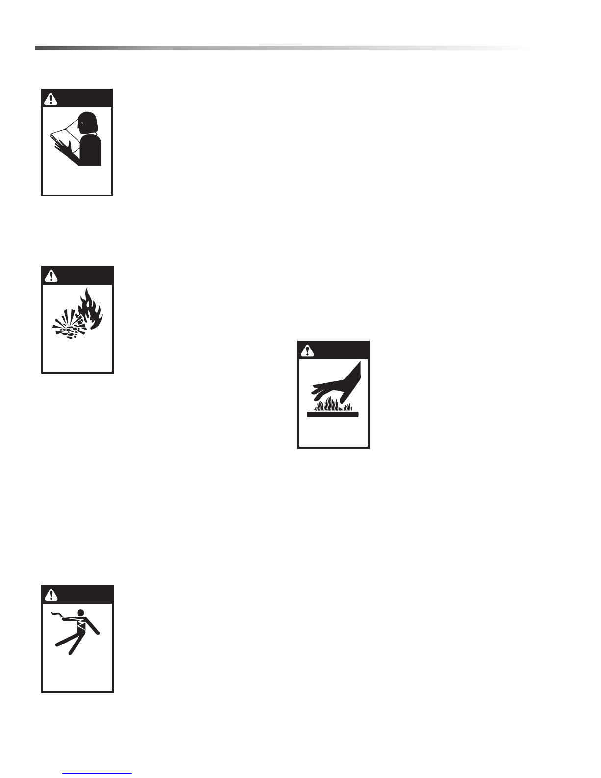
WARNING
READ OPERATOR’S
MANUAL THOROUGHLY
PRIOR TO USE.
OPERATIONS
SAFETY
MAINTENANCE
WARNING
RISK OF EXPLOSION:
AVOID FLAMMABLE
LIQUIDS.
DANGER
KEEP WATER
SPRAY AWAY FROM
ELECTRICAL WIRING.
WARNING
EXTREMELY HOT:
USE CAUTION WHEN
OPENING LID
General Safety Information
WARNING: T o reduce the risk of
injury, read operating instructions carefully before using.
AVERTISSEMENT: Pour réduire
le risque de blessures, lire
attentivement les instructions
de fonctionnement avant
l'utilisation.
1.Read the owner’s manual thor-
oughly. Failure to follow instructions could cause a malfunction of the parts washer
and result in death, serious bodily injury and/or
property damage.
WARNING: This is a heated
parts cleaner. Use only
nonflammable, noncombustible, water-based cleaning
compounds in this machine. Do
not fill or contaminate with any
flammable or combustible
material such as gasoline,
alcohol, mineral spirits, etc.
Drain parts to be cleaned of any
combustible or flammable
material before placing inside cabinet. Failure to
observe this warning will create an extremely
hazardous condition.
AVERTISSEMENT: Ceci est un nettoyant pour les
pièces chauffées. Utiliser uniquement des produits
de nettoyage à base d'eau, ininflammable et non
combustible dans cette. Ne pas remplir ou
contaminer avec une substance inflammable ou
combustible comme de l'essence, de l'alcool, de
l'essence minérale, etc. Drainer les pièces à
nettoyer de toute substance combustible ou
inflammable avant de les placer à l'intérieur de
l'armoire.Le non-respect de cet avertissement
créera une condition extrêmement dangereuse.
DANGER: Keep water away
from electric wiring or fatal
electric shock may result.
DANGER:
l'écart de tout câblage électrique
ou des chocs électriques mortels
pourraient survenir.
2.All installations must comply
with local codes. Contact your
Garder le jet d'eau à
electrician, plumber, utility company or the selling
dealer for specific details.
Install the machine in compliance with the National
Electric Code. Connect to a properly sized lockable
disconnect and ground machine using the
grounding stud inside the main electrical panel.
3. Do not locate this machine in the vicinity of any
flammable vapor, liquids or solids.
4. To protect the operator from electrical shock, the
machine must be electrically grounded. It is the
responsibility of the owner to connect this machine
to a grounded receptacle of proper voltage and
amperage ratings. Do not touch machine with wet
hands or while standing in water. Always disconnect the power before servicing.
5. Do not touch machine with wet hands or while
standing in water. Always disconnect the power
before servicing.
6. Never make adjustments on machine while it is in
operation except those prescribed in this manual.
WARNING: Us e extreme caution
when opening the door of this
parts washer. Hot water/
detergent vapors will be
emitted. Stand Back! Hot
cleaning solution could cause
serious injury.
AVERTISSEMENT:
Faire preuve
d'extrême prudence au moment
d'ouvrir le volet de cette partie de
la laveuse. De l'eau chaude/des
vapeurs de détergent seront émises. Se tenir à l'écart!
Une solution de nettoyage chaude haute pression
pourrait causer des blessures graves.
7. Before servicing the machine, refer to all safety
data sheets (SDS’s) on the material identified in
the waste stream. You must comply with all
warnings and wear all protective clothing stated on
the SDS.
WARNING: Slips and falls from wet surfaces could
cause serious injury.
AVERTISSEMENT:
Les chutes et les trébuchements
causés par des surfaces humides pourraient causer
des blessures graves.
8. Use caution when lifting items in and out of parts
basket to prevent back injuries.
6
Cuda 2412 Operator’s Manual 8.914-384.0 - V
Page 7

9. When the machine is working, do not cover or
place in a closed space where ventilation is insufficient. Avoid installing machines in small confined
areas.
10. In cold climates, this parts washer will freeze if not
in operation and must be located in a heated enclosure.
11. Maintain an unobstructed work area around the
machine and keep the floor free of water, oil,
grease or other foreign substances.
12. Always ensure that your parts washer is clean.
Pump and heating elements could be damaged by
continued build-up of sludge.
13. Check water level daily. Never allow water level to
drop below pump inlet screen or heating elements.
14. Before discarding the spent washing solution,
check with your local EPA or sewer district for
disposal regulations.
15. Do not operate the machine with the lid or door
open and do not override the safety switch.
Safety
16. After the machine stops, wait 10 seconds before
opening the lid or door.
This automatic parts washer is designed to operate
safely and efficiently. Before you begin to install and
use the machine, please familiarize yourself with the
major components.
Cuda 2412 Operator’s Manual 8.914-384.0 - V
7
Page 8
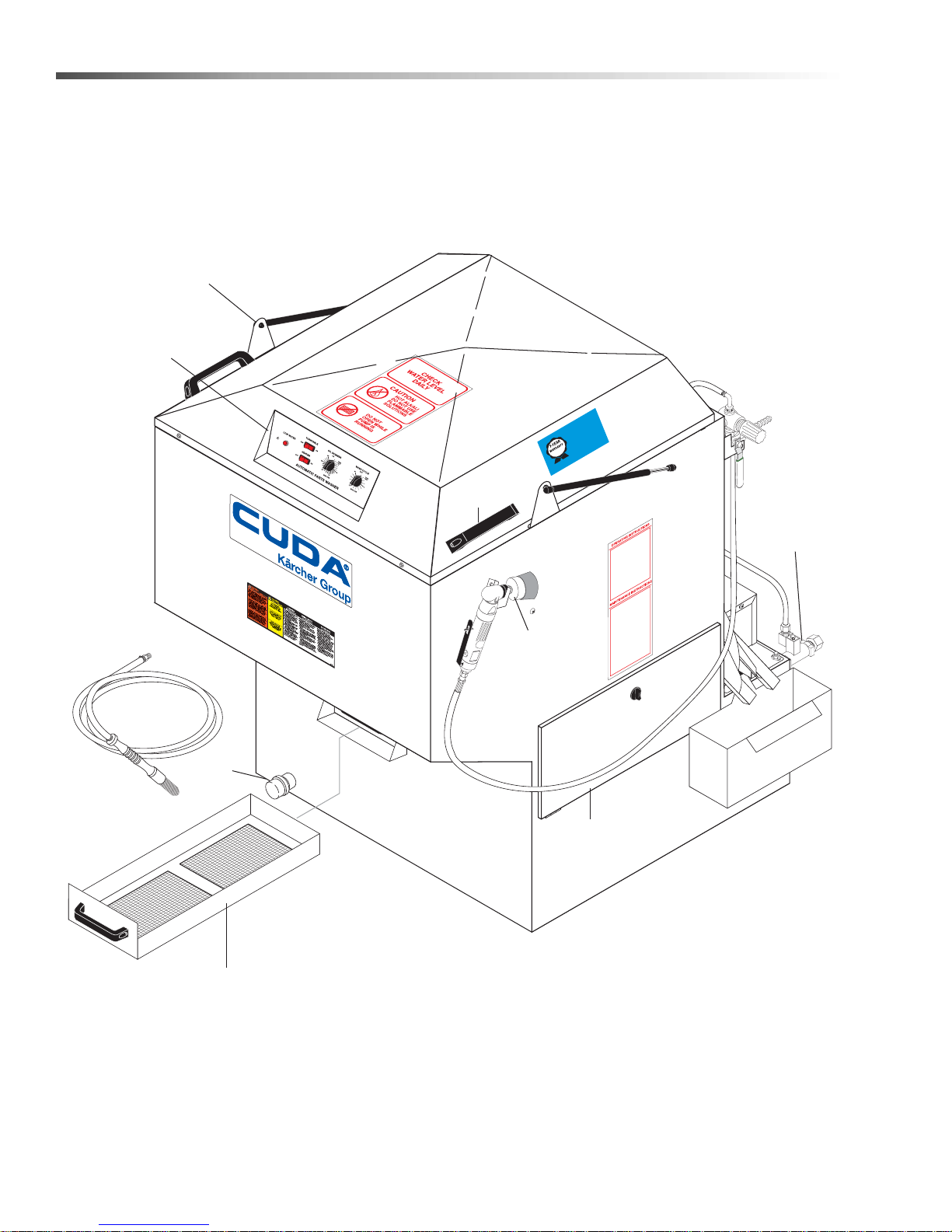
Operations
Control Panel
Lid Support
Strut
Power Brush
(Optional)
Sump
Drain
Access
Panel
Lid
Handle
Detail
Brush
(Optional)
Debris Screen
Autofill
(Optional)
Component Identification - Front View
VED
O
R
DA APP
O EXTEND
T
O 1-YEAR!
T
S
Y CU
Y
ATTENTION
G) PER
ER
L
T
A
W
B (1/2 K
visit
USE ON
S 1 L
nts
WARRANT
DETERGENT
ge
ITERS) OF
0
3.
NS (15 L
LABOR
sa.com or
07-51
DETERGENT
ved Deter
LO
o
9.8
r
D
AL
MIX
E
.cudau
T
5-G
I
Y
A App
ww
D
ANT
IM
//w
RR
L
A
W
call 888-319-0882
http:
OR
For CU
USE OF
Y LAB
NTS
A
LUSIVE
90-D
XTENDS TO 1-YEAR
E
DETERGE
A
ITH EXC
W
CUD
8
Cuda 2412 Operator’s Manual 8.914-384.0 - V
Page 9
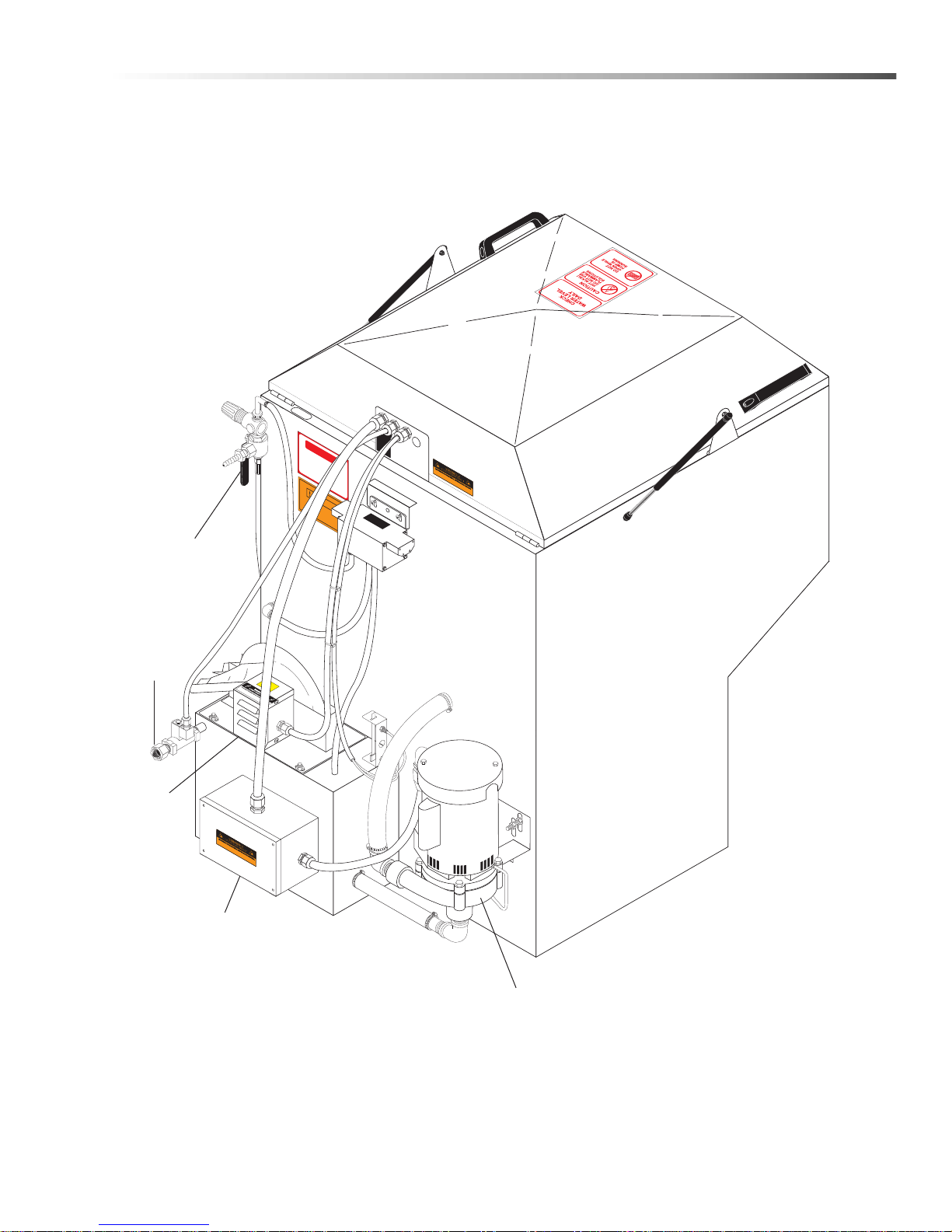
Component Identification - Rear View
DANGER
HIGH VOLTAGE
WARNING
HOUR
METER
KEE
P
DR
Y
Air Flow
Valve & Flow
Regulator
(Optional)
Heating Element
& Thermostat
Pump
Oil
Skimmer
Water
Inlet
(Optional)
Operations
Cuda 2412 Operator’s Manual 8.914-384.0 - V
9
Page 10
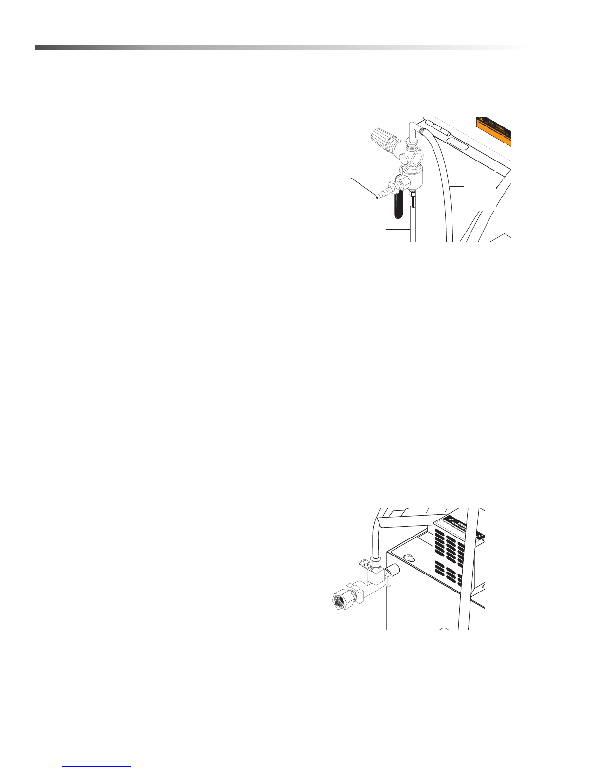
Operations
Hose
Connection
(Optional)
To Power Brush
Connection
Line to
Detail
Brush
Pump
Compressed
Air
Connection
Installation
Before You Begin
To prepare to install the machine, choose an unobstructed, level site that allows convenient access for
operators and maintenance personnel. Sources for
water and electrical power should be located near the
installation site. If your machine is equipped with the
optional power brush and hand detail brush you
must also run a compressed air line to the
installation site.
If you have any questions regarding the installation,
please contact your dealer and have the machine identification number available for the dealer to reference.
Your machine identification tag is located inside the
front cover of this manual for detailed machine specifications.
Step 1: Make Electrical Connections
NOTE: All electrical installation tasks must be
performed by a licensed, professional electrician to
ensure safe and proper operation. The installation
must comply with the National Electric Code and all
applicable state and local codes.
The machine can only operate on the type of electrical
power indicated on the machine identification tag. Read
and understand the machine identification tag to
determine the electrical power requirements before
installing the machine.
Step 2: Connect A Compressed-air Line
And Accessories (Optional)
This step is required for machines equipped with
the optional power brush and hand detail brush.
If your machine does not have these options,
skip the following procedure.
2. Familiarize yourself with the three-way air flow
valve, then install a fitting (if necessary) to accommodate a connection to your compressed-air
supply.
3. Connect the shop compressed-air line to the
machine.
4. Connect the hose from the power brush to the air
flow valve.
5. Hang the power brush on the bracket mounted
along the right side of the machine.
Step 3: Connect A Water Line
This step is required for machines equipped with the
optional automatic water fill feature. If your machine
does not have this option, skip this step.
The optional automatic water fill feature automatically
maintains the correct water level in the sump. The
feature requires that you connect the machine to a
dedicated water supply line.
To connect the machine to a water supply line, attach a
suitable burst-proof hose to the hose connection on the
rear of the machine, then connect the hose to a nea rby
water spigot.
NOTE: To ensure proper operation and to minimize
the possibility of premature component failure, make
sure the compressed air is supplied at 75 to 90 psi.
We also recommend an in-line moisture trap and
an in-line lubricator on the main air supply line.
Refer to the documentation provided with the power
brush for more information.
1. Remove the power brush from the box, install the
wire brush in the chuck, and connect the air hose.
10
NOTE: The machine is designed for portability, and
some maintenance tasks require that you move the
machine. DO NOT make a permanent connection
from your shop water supply to the machine.
Cuda 2412 Operator’s Manual 8.914-384.0 - V
Page 11

Operations
Magnet Aligned
w/Lower Switch
Magnet Aligned
w/Upper Switch
Step 4: Fill The Machine With Water And
Add Detergent
1. Familiarize yourself with the low water shut-off
system on the left side of the machine.
2. Fill the sump with water.
If your machine is equipped with the optional
automatic water fill feature, simply turn the water
on; the automatic water fill feature will automatically turn off the water when the sump is full.
If your machine is not equipped with optional
automatic water fill feature, add water through the
wash chamber until the low water shut-off system
indicates that the sump is full. The sump capacity
is 25 gallons.
container and then pouring the dissolved detergent
into the sump.
NOTE: Factory approved detergent is the only
detergent approved for use with this automatic parts
washer. It is specially formulated with rust inhibitors
and anti-foaming agents to optimize performance and
minimize maintenance. The use of any other
detergent during the warranty period will void the
warranty. In addition, using factory detergents will
extend your 90 day labor warranty to 1 year.
6. Turn the wash cycle timer and allow the machine to
complete the cycle to dissolve the detergent into
the water. When the machine stops, it is ready for
use. Refer to Operation for complete operating
instructions.
3. Close the lid.
4. Flip the heater switch to the ON position.
The sump water will reach operating temperature
(160°-180°F Excludes 120V Version 1.043-356.0)
in approximately four hours.
To avoid having to wait for the wash solution to
heat up before you use the machine each day,
install an optional 24-hour 7-day heater timer.
Refer to 24-hour, 7-day Heater Timer for more
information.
IMPORTANT: Allow the sump water to reach
operating temperature before adding detergent
and running the machine. If you add detergent and
run the machine when the sump water is cool, the
detergent will foam excessively and could overflow
the machine.
5. While the sump water is heating, add the appropriate quantity of factory approved detergent to the
wash chamber. We recommend mixing the
detergent with warm water in a separate bucket/
Cuda 2412 Operator’s Manual 8.914-384.0 - V
11
Page 12
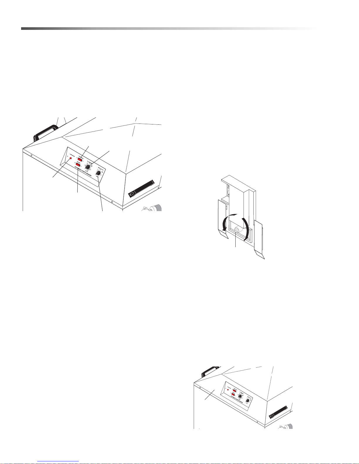
Operations
Lid Safety
Switch (Located
Behind Lip)
Low Water
Indicator
Oil Skimmer
Timer w/Knob
Wash Cycle
Turntable
Switch
Heater Switch
Adjustment
Screw
Decrease
T
emperature
Increase
T
emperature
Operations
Main Operating Components
Familiarize yourself with the main operating components before operating the machine.
Control Panel
The control panel is located on the front center of the
lid. It contains the heater, wash cycle, turntable
controls, and low water indicator.
for a period of time to allow the wash solution to
reheat to operating temperature.
Wash Cycle Control
The wash cycle control is a timer switch. When set, the
timer automatically shuts off the pump and turntable
when the wash cycle is complete.
Thermostat
The thermostat is located inside pump enclosure. The
thermostat is factory-set to heat the wash solution to a
maximum temperature of 180°F (Excludes 120V
Version 1.043-356.0).
Adjusting the Thermostat
To adjust the thermostat, rotate the adjustmen t scr ew
or knob clockwise to increase the temperature, or counterclockwise to decrease the temperature.
Timer w/Knob
Low Water Indicator
The low water indicator light illuminates if the wash
solution in the sump is low. For more information refer
to Low Water Shut-off Syste m.
Turntable Switch
The turntable switch is an illuminated rocker switch that
enables you to disconnect power to the turntable motor .
Set to ON, the turntable rotates during the wash cycle.
Set to OFF, the turntable does not rotate during the
wash cycle. The switch is useful for washing large parts
that would otherwise impede turntable rotation.
Heater Control
The heater control is an illuminated rocker switch. It
controls the heating element in the sump chamber . The
heater control illuminates when the heating system is
on. The heating system is thermostatically set at the
factory to reach a high temperature of 180 °F (Excludes
120V Version 1.043-356.0). The temperature is adjustable using the thermostat (See Thermostat).
NOTE: The machines contain an internal power relay
that automatically disconnects power to the heater
when the pump turns on; the heater and pump cannot
run simultaneously (120V only). After long wash
cycles it may be necessary to let the machine sit idle
12
24-hour, 7-day Heater Timer
A 24-hour, 7-day heater timer is available as an option
on these machines. The timer plugs directly into a 15amp outlet and automatically cycles the heating system
on and off each day. To configure the timer, refer to the
instructions printed on the back of the timer housing.
To order a 24-hour, 7-day heater timer, contact your
dealer or call customer service.
Lid Safety Switch
The lid safety switch is located behind the front left lip of
the lid, just below the control panel. The safety switch
disconnects power to the water pump and the turntable
motor if the lid is raised during operation.
Cuda 2412 Operator’s Manual 8.914-384.0 - V
Page 13
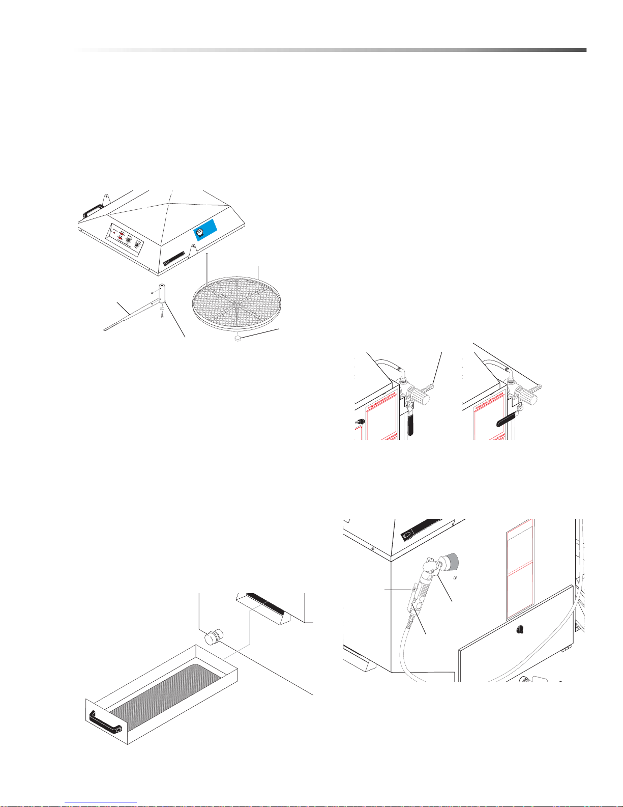
Operations
Throttle
ever Lock
Throttle
Lever
Holding
Bracket
Thrust
Bearing
Turntable
Turntable Drive
Bar
Position #2 For
Power Brush
Position #1 For
Detail Brush
Compressed
Air In
Turntable Assembly
The turntable assembly uses a torque arm mounted on
the underside of the lid to rotate the turntable. The
torque arm includes a torque limiter which prevents the
turntable motor from burning out in case a part falls off
the turntable and obstructs rotation. For information on
adjusting the torque limiter, refer to T orque Limiter. For
information on replacing the turntable motor, refer to
Turntable Moto r.
VED
O
!
A APPR
EXTEND
D
1-YEAR
O
R
T
O
TTENTION
CU
T
PE
S
Y
A
LY
TER
A
/2 KG)
W
t
(1
OF
TERGENT
ARRANT
USE ON
ERS)
W
TS 1 LB
ents visi
T
DE
I
g
R
r
0
om or
ERGEN
c
Dete
-513.
LABO
ved
o
9.807
r
D
p
MIX DET
E
.cudausa.
19-0882
5-GALLONS (15 L
Ap
w
IT
Y
T
N
DA
M
88-3
A
ww
R
LI
AR
tp://
call 8
or CU
R W
OF
ht
E
1-YEAR
F
S
BO
U
LA
TO
S
T
Y
IVE
A
EN
D
US
G
ENDS
0-
T
R
9
EX
TE
E
EXCL
D
TH
A
D
WI
U
C
Torque Limiter
Removing the Turntable
The frequency at which you must clean the debris
screen depends on machine usage. In general, you
should clean the screen before operating the machine
each day. To access and remove the screen you must
remove the turntable (see Removing the Turntable).
NOTE: Never operate the machine without the debris
screen in place. The screen is specially sized to filter
particles that could clog the spray nozzles or damage
the water pump. Operating the machine without
the debris screen in place could cause spray
nozzle clogging or water pump failure.
Air Flow V alve (Optional)
The air flow valve is located on the right rear corner of
the machine. It is a three-way ball valve that controls
the flow of compressed air to the power brush and the
hand detail brush.
To remove the turntable, grasp it evenly on opposite
sides and lift it free of the spindle.
Important: The turntable rotates on a thrust bearing
inside of the hub. As yo u lift the turntable free of the
spindle, take care not to jar the thrust bearing loose. If
the thrust bearing drops out of the hub, inspect it for
wear then either replace it or re-install it.
Debris Screen
The debris screen is located below the turntable inside
of the wash chamber. The debris screen continuously
filters debris particles from the cleaning solution to
ensure blockage free spray nozzle operation, and also
provides a safeguard against small parts that might
accidentally be washed through from the wash
chamber.
Power Brush (Optional)
The power brush is located on the right front corner of
the machine. Refer to Connect a Compressed-Air
Line and Accessories for detailed inst allation information.
L
Cuda 2412 Operator’s Manual 8.914-384.0 - V
NOTE: The power brush is available as an option on
this machine. For ordering information, contact your
dealer or call customer service.
13
Page 14
Operations
Tank Wall
Flow
Regulator
Detail
Brush
Skimmer
Disc
Motor
Skimmer
Container
Using the Power Brush
WARNING: Particles d islo dged by t he power br ush
could cause serious injury to your eyes. Alwa ys
wear approved eye protection when using the
power brush.
With stiff stainless steel bristles turning at 1800 RPM,
the power brush easily removes carbon depo s its, old
gasket material, or other tightly-adhered materials fr om
parts before washing.
To turn on the power brush, position the air flow select
valve appropriately, then push the power brush lever
lock forward with your thumb and squeeze the throttle
lever to control the speed of the brush.
Detail Brush and Flow Regulator
(Optional)
The detail brush is located on the front inside wall of the
wash chamber. The flow regulator is located on the
right rear corner of the machine. The detail brush uses
a continuous flow of hot cleaning solution through its
nylon bristles to help you clean delicate or lightly soiled
parts. The flow regulator controls the flow of cleaning
solution through the detail brush.
Adjusting the Flow of Cleaning Solution
The flow of cleaning solution through the detail brush is
pre-set at the factory . If you need to adjust the fl ow, pull
out the flow regulator knob, then rotate it clockwise to
decrease the flow or counter-clockwise to increase the
flow. After adjusting, push the knob back in to lock it.
NOTE: The detail brush is available as an option on
this machine. For ordering information , co nta ct you r
dealer or call customer service.
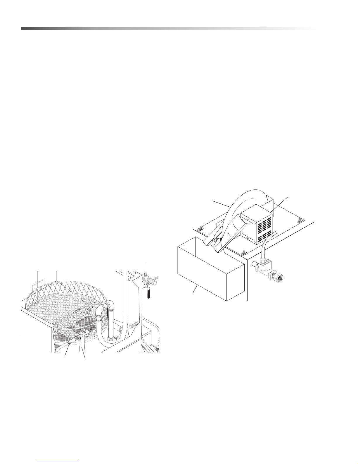
Automatic Oil Skimmer System
The automatic oil skimmer system consists of a
skimmer assembly that includes an electric motor that
rotates a disk in the sump water. The oil adhe res to the
disk and is wiped off by wiper blade s and deposited in a
container. The gear motor is controlled by a timer
switch on the control panel. See information in Using
the Oil Skimmer for detailed operation.
Skimmer
WARNING: Hot, high-pressured cleaning solution
could cause serious injury. Always wear rubber
gloves and approved eye protection when handlin g
hot cleaning solution.
Collection
14
Cuda 2412 Operator’s Manual 8.914-384.0 - V
Page 15
Operations
Magnet Aligned
w/Lower Switch
Magnet Aligned
w/Upper Switch
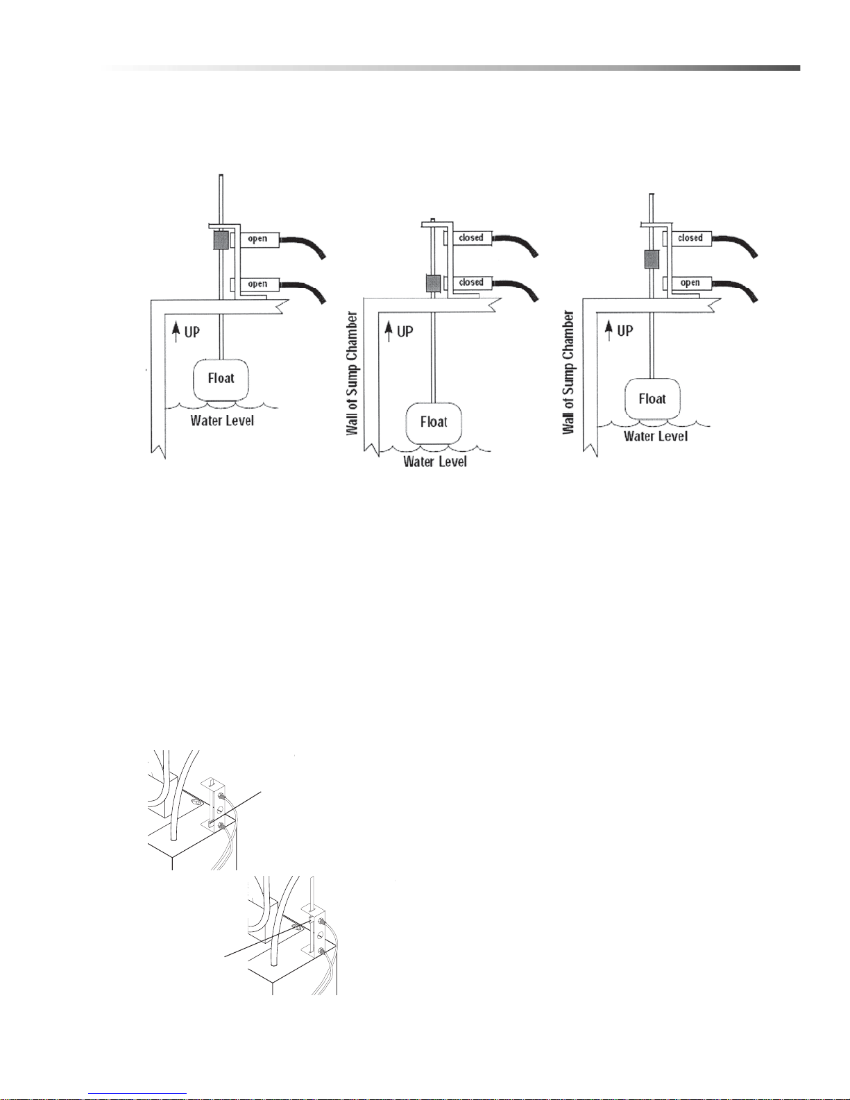
WATER LEVEL OK:
Both Switches OPEN, Automatic
Water Fill Valve (if installed)
CLOSED, Heating Element ON.
LOW WATER LEVEL
Top Switch CLOSED, Bottom Switch
CLOSED, Automatic Water Fill Valve (if
installed) OPEN, Heating Element O.
SUMP FILLING:
Top Switch CLOSED, Bottom Switch
OPEN, Automatic Water Fill Valve (if
installed) OPEN, Heating Element OFF.
Water Level
Under typical operating conditions the machine loses 3
to 5 gallons of water per day to evaporation. It is
important that you monitor and maintain the water level
daily to minimize the risk of burning out the heating
element or ruining the pump.
NOTE: Add detergent each time you add water. Add
detergent after you clean the sump chamber each
month, and more frequently if your cleaning cycle
maintenance period is more frequent, and if you
notice specific low-detergent indicators (See
Detergents and Additives).
Low Water Shut-off System
The low water shut-off system shuts down the machine
if the wash solution in the sump chamber drops below a
safe level. The system uses two reed switches and a
float rod mounted on the right outer wall of the sump
chamber to control the water level.
If the wash solution drops below the lower reed switch,
the low water indicator light on the control panel turns
on and the system disconnects power to the heating
element, the pump, and the turntable motor. To reset
the system, add water to the sump until the low water
indicator light turns off.
Automatic Water Fill (Optional)
The automatic water fill system automatically maintains
a proper water level in the sump. It is available as on
option on these machines.
The automatic water fill system uses the low water
shut-off reed switches to open and close a water
solenoid valve, which automatically maintains a proper
water level in the sump. The figure above d escribes the
operation of the automatic water fill system.
Cuda 2412 Operator’s Manual 8.914-384.0 - V
15
Page 16

Operations
Detergents And Additives
Detergents
Manufacturer's detergents are the only detergents
approved for use with our Automatic Parts washers.
They are specially formulated with rust inhibitors and
anti-foaming agents to optimize performance and
minimize maintenance. The use of any other deter gent
during the warranty period will void the warranty. To
monitor the relative concentration of the detergent in
the wash solution, periodically examine the was h
solution in the sump chamber for the following
indicators:
• Rust inside the machine: not enough
detergent
• Excessive foaming: not enough detergent
• Thick, white residue on parts after washing:
too much detergent
To maintain proper detergent concentration under
typical operating conditions, add detergent each month
after cleaning the sump chamber. Follow recommended detergent quantities. Use pH kit to determine
the proper amount of detergent to use. If you n eed help
interpreting test results, contact customer service.
Rust Inhibitor Additive
Factory detergents protect the entire inside of your
machine against the degenerative effects of water
evaporation. A rust inhibitor additive actually evaporates with the water and continuously coats and
protects metal surfaces, even while your machine is
sitting idle. For more information, contact your dealer or
call customer service.
Washing Parts
The following procedure assumes that the heater is on
and the sump water is at operating temperature.
To wash parts, perform the following procedure.
WARNING: Hot, high-pressured cleaning solution
could cause serious injury. Always wear rubber
gloves and approved eye protection when loading
and unloading the machine.
1. Load large, heavy parts directly onto the turntable.
Load small, light parts in the small parts basket, if
available. Make sure none of the parts extend
beyond the edge of the turntable and make sure
large, light parts (valve covers, for example) are
secured to the turntable.
NOTE: For optimum cleaning performance, provide a
slight clearance between parts to allow adequate flow
of cleaning solution around and between them.
2. Close the lid.
NOTE: If you are washing large parts that might
impede turntable rotation, flip the turntable switch
OFF.
3. Set the wash cycle timer.
4. When the machine stops, lift the lid and wait a few
moments to allow the parts to cool and dry before
removing them. Most parts flash-dry in seconds.
Preparing The Machine For Use
Before you begin to wash parts, it is important that you
properly prepare the machine. Before you be gin to u se
the machine each day:
• check the water level and add water to the
sump tank if necessary;
• heat the water to operating temperature
• add detergent if necessary (see Detergents
and Additives);
• verify that none of the spray nozzles are
clogged; and
• clean the debris screen.
16
Cuda 2412 Operator’s Manual 8.914-384.0 - V
Page 17
Operations
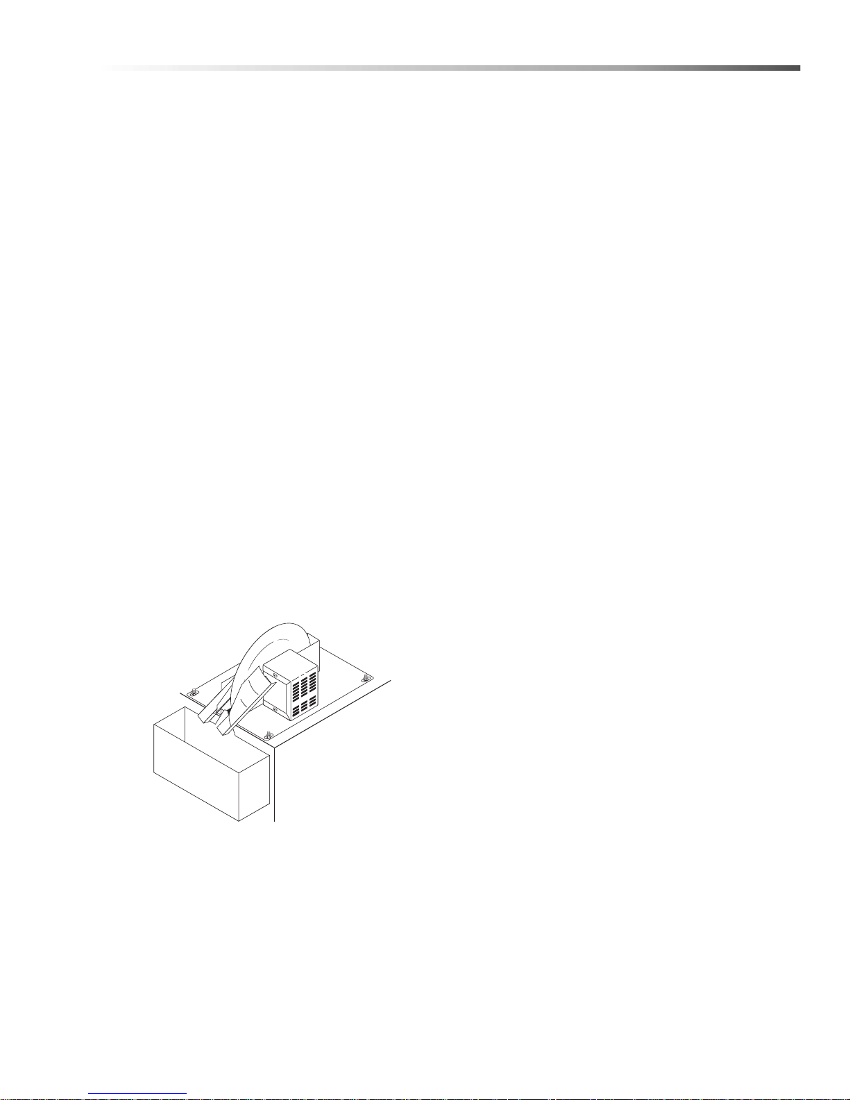
Oil Skimmer
Assembly
Oil Container
Using the Oil Skimmer System
The oil skimmer system is most effective if used when
the cleaning solution in the sump is cool. Th e frequency
at which you must remove the oil from the wash
solution will depend on machine usage. Under typical
operating conditions you may need to remove the oil
every day. If the oil skimmer runs longer than 10-15
minutes, the detergent and vapor rust inhibitor content
in the sump should be checked. The detergent and
inhibitor can be removed with extensive use of the
skimmer, so be certain to check chemical levels after
running the skimmer to determine if you require a
higher frequency chemical maintenance cycle than
weekly.
IMPORTANT: The skimmer motor is equipped with a
thermal overload switch which protects the skimmer
from overheating. If you attempt to use the oil skimmer
system when the wash solution is hot, the thermal
overload will probably trip and the motor will shut off
until it cools. Under normal skimming conditions ( when
the wash solution is cool) the thermal overload should
not trip.
To remove oil from the cleaning solution, perform the
following procedure:
4. Dispose of the oil in the collection container in
accordance with local and state regulations, then
replace the container.
1. Allow the machine to sit idle for at least 30 minutes
to allow the oil to float to the surface of the wash
solution.
2. Ensure that the oil collection container is in place,
then turn the skimmer switch to the “ON” position.
3. Allow the oil skimmer to operate until it is no longer
extracting oil from the cleaning solution.
Tip: While extracting oil from the cleaning solution, oil
will flow off the wiper blades in a fine continuous
stream. Water will flow off the blades in droplets. Once
droplets begin to flow off the wiper blades, stop the
skimmer motor.
Cuda 2412 Operator’s Manual 8.914-384.0 - V
17
Page 18

Operations
Shutting Down The Machine
To shut down the machine at the end of the day:
• set the wash cycle control to OFF;
• shut off the compressed air at the supply line
(if installed).
WARNING
• For periods of extended shut-down
(weekends and holidays, for example), disconnect power to the machine.
• If your machine is equipped with an optional
programmable heater timer, periodically
verify the settings to prevent inad ve rte n t
unattended operation.
18
Cuda 2412 Operator’s Manual 8.914-384.0 - V
Page 19
Maintenance
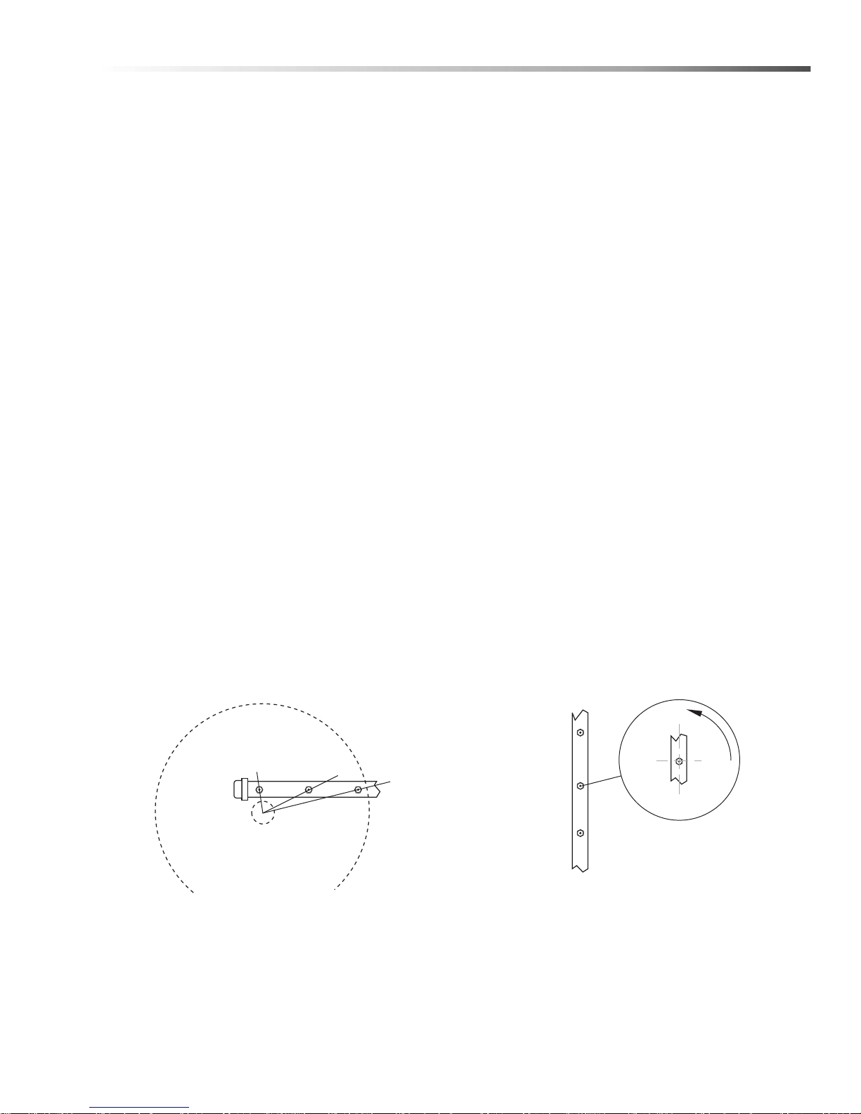
Align The Notch In
Each Spray Nozzle
With The Center Of
The Turntable
TOP & BOTTOM NOZZLES SIDE NOZZLES
Rotate Each Nozzle
Approximately 3°
From
The Center Line
Of The Pipe
3°
Turntable
C
L
Maintaining The Machine
To ensure optimum performance and trouble-free operation, observe the following maintenance schedule
consistently.
Daily Maintenance
• Check the water level; add water if necessary.
• Clean the debris screen.
Weekly Maintenance
• Detergent Concentration Level: Check
detergent level weekly to maintain concentration level, which decreases when water is
added. The pH level of this detergent must be in
accordance with the detergent manuf act ur e r's
recommendation.
• Remove oil and grease from the wash solution
by using the oil skimmer.
• For oily or extremely soiled parts, it is recommended the oil skimmer be operated on a more
frequent basis.
• Examine spray nozzles; clean and align if
necessary (See Cleaning and Aligning the
Spray Nozzles).
• Wipe down the exterior of the machine using
spray degreaser and a soft, damp cloth. TO
PREVENT ELECTRICAL COMPONENT
FAILURE, DO NOT SPRAY THE MACHINE
WITH WATER.
NOTE: Degreaser spray and a damp cloth will
usually remove all dirt and grime from the machine.
For particularly stubborn soap deposits, use a soft
cloth dampened with warm solution from the wash
chamber.
Monthly Maintenance
• Drain and clean out the sump chamber
(See Cleaning out the Sump).
Cleaning and Aligning the Spray Nozzles
To ensure optimum cleaning performance, it is
important that you examine the spray nozzles periodically and clean and align them if necessary. To clean a
plugged nozzle, remove it from the spray pipe and use
a small wire brush to free the nozzle of any obstructions. When you replace the nozzle on the spray pipe,
make sure you align it according to figure to maintain a
proper spray pattern.
NOTE: The spray nozzles are sized and positioned to
optimize the distribution of cleaning solution in the
wash chamber. If you remove the nozzles make sure
you replace them in the correct position on the
appropriate pipe. Spray nozzle specifications are
stamped on the face of each nozzle, as shown.
Cuda 2412 Operator’s Manual 8.914-384.0 - V
19
Page 20
Maintenance
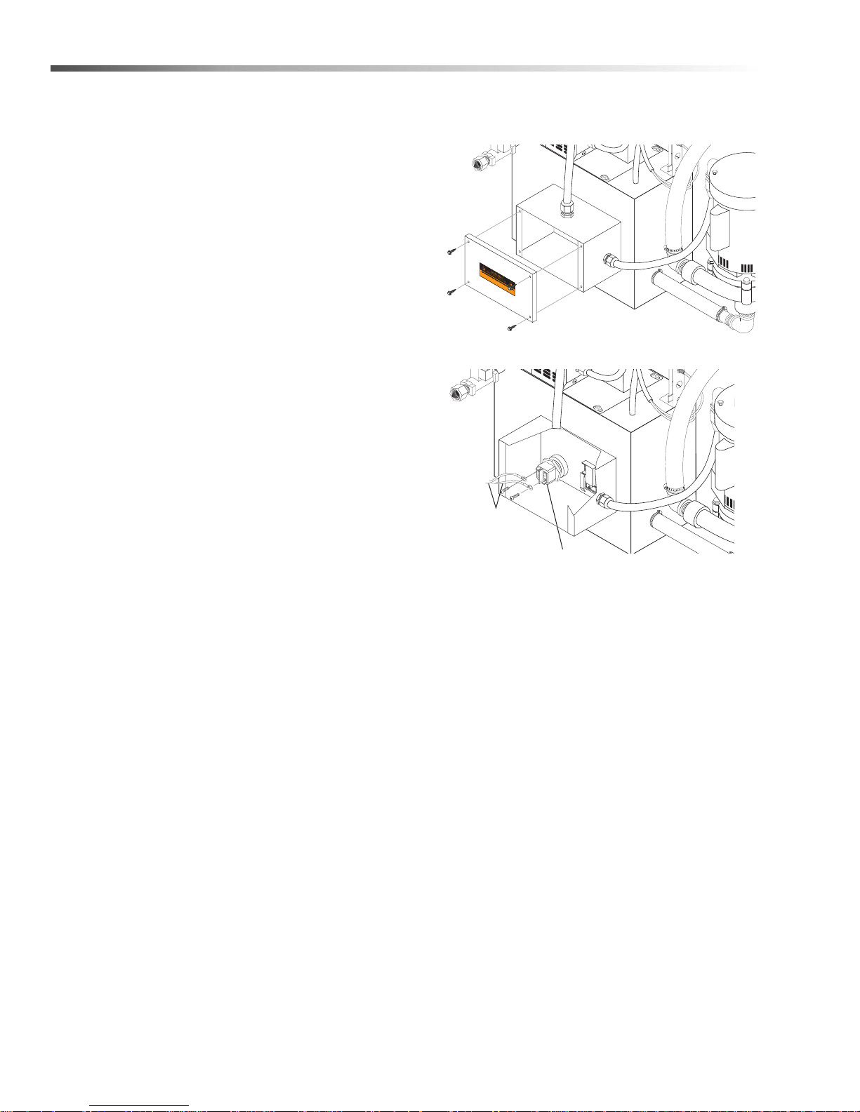
Heating
Element
Power
Leads
Cleaning out the Sump
1. Remove oil from the cleaning solution using the oil
skimmer.
2. Remove the debris screen.
3. Drain the wash solution from the sump chamber.
To drain the solution either use the sump drain
or a small submersible pump.
4. Remove sand and other debris from the bottom of
the sump chamber. To remove the debris either
flush it out through the sump drain, or vacuum it out
using a wet/dry vac. Dispose of the debris in accordance with applicable local, state, and federal
regulations.
NOTE: Take special care to ensure that the heat ing
element and the low-water float are free of debr i s.
A build up of debris around the heating element will
decrease heating performance and may cause the
element to overheat and fail. A build up of debris
around the float may cause the low water shut-off
system to malfunction (See Low Water Shutoff
System)
3. Remove the rear panel from the machine (four
screws; use a 5/16” wrench or socket).
4. Detach the power leads from the heating element.
5. Replace the debris screen.
6. Heat the wash water to operating temperature,
then add appropriate amount of factory detergent.
7. Run the machine through a 15-minute wash cycle.
Repairing The Machine
The following procedures outline the steps necessary
to replace specific items on the machine that could
wear out or otherwise fail.
Heating Element
Required Tools and Equipment
• 5/16" wrench or socket
• 1-1/2" socket and breaker bar
• sealing tape or compound
• medium phillips-head screwdriver
Replacement Procedure
1. Disconnect power to the machine.
2. Drain the wash solution from the sump.
5. Using a 1-1/2" socket and breaker bar , unscrew the
heating element from the machine.
NOTE: Since the heating element is in continuous
contact with the cleaning solution the threads may
corrode slightly. The element may be difficult to
remove. When you install a new heating element, use
sealing tape or compound on the threads to deter
corrosion, and be sure to install the rubber ga ske t to
prevent leakage.
6. Install the new heating element. Installation is the
reverse of removal.
20
Cuda 2412 Operator’s Manual 8.914-384.0 - V
Page 21
Maintenance
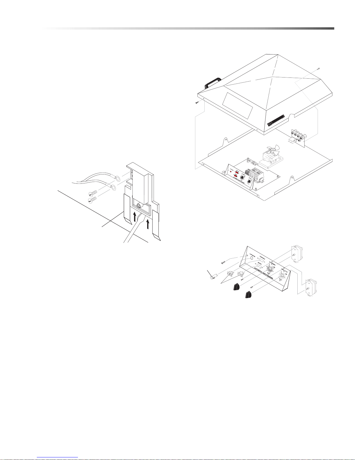
Mounting
Bracket
Low Water
Indicator
Wash Cycle
Timer
Switches
Oil Skimmer
Timer
AUT
OMATIC P
ARTS W
ASHER
Screw
Screw
Thermostat
Required Tools and Equipment
• 5/16” wrench or socket
• medium phillips-head screwdriver
• large flat-head screwdriver
Replacement Procedure
1. Disconnect power to the machine.
2. Remove the rear panel from the machine (ten
screws; use a 5/16” wrench or socket).
3. Detach the power leads.
4. Using a large flat-head screwdriver, pry the thermostat out of the mounting bracket, then remove it
from the machine.
3. Remove the lid cover (four screws use a 5/16”
wrench or socket).
4. From the rear of the control panel, remove the
power leads from the component you wish to
replace, then remove the component.
Screwdriver
5. Install the new thermostat. Installation is the
reverse of removal.
NOTE: When you install the thermostat make sure
you press it firmly into the mounting bracket. In order
to operate correctly, the thermostat must be in direct
contact with the rear wall of the sump chamber.
Timers and Switches
on the Control Panel
Required Tools and Equipment
• 5/16" wrench or socket
• 1/2" wrench or deep socket
• small phillips-head screwdriver
• small flat-head screwdriver
Replacement Procedure
1. Disconnect power to the machine.
2. Close the lid.
5. Replace the component, then reassemble the lid
cover.
6. Ensure thermostat is set to 180°F.
Cuda 2412 Operator’s Manual 8.914-384.0 - V
21
Page 22
Maintenance
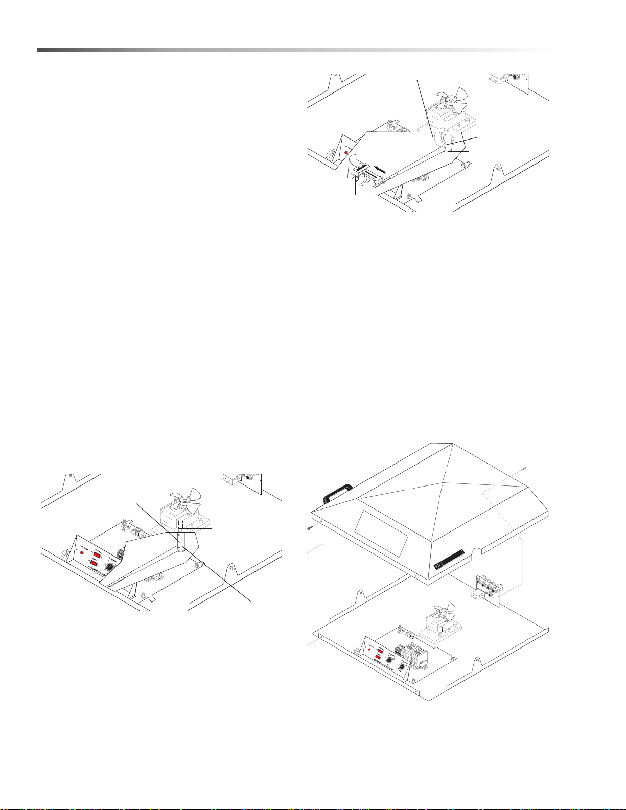
Adjusting Bolt
Set Screw
Torque
Limiter
Locking Pliers
Adjusting Bolt
Spring Scale
Torque Limiter
AUT
OMATIC P
ARTS W
ASHER
Screw
Screw
Cleaning and Aligning the Spray Nozzles
To ensure optimum cleaning performance, it is
important that you examine the spray nozzles periodically and clean and align them if necessary.
To clean a plugged nozzle, remove it from the spray
pipe and use a small wire brush to free the nozzle of
any obstructions. When you replace the nozzle on the
spray pipe, make sure you align it according to figure to
maintain a proper spray pattern.
NOTE: The spray nozzles are sized and positioned to
optimize the distribution of cleaning solution in the
wash chamber. If you remove the nozzles make sure
you replace them in the correct position on the
appropriate pipe. Spray nozzle specifications are
stamped on the face of each nozzle, as shown.
Torque Limiter
The torque arm should begin to slip at 7 pounds. If it
slips at less than 7 pounds, tighten the adjusting bolt. If
it slips at greater than 7 pounds, loosen the adjusting
bolt.
5. Remove the locking pliers from the hub, then
tighten the set screw.
The torque limiter prevents the turntable motor from
burning out in case a part falls off the turntable and
obstructs rotation. The torque limiter is pre-set at the
factory, but you may need to adjust it if the turntable
begins to slip or bind.
Adjusting the Torque Limiter
To adjust the torque limiter, perform the following
procedure;
1. Raise the lid.
2. Loosen the torque limiter set screw (use a 1/8”
allen wrench).
Turntable Motor
The turntable motor is located near the main electrical
panel beneath the lid cover. To replace the turntable
motor, perform the following procedure:
1. Disconnect power to the machine.
2. Close the lid.
3. Remove the lid cover (four screws use a 5/16”
wrench or socket).
3. Rotate the torque arm 180°
4. Clamp the hub against the top spray arm with a
pair of locking pliers, then use a spring scale on the
end of the torque arm to measure the torque
setting.
22
Cuda 2412 Operator’s Manual 8.914-384.0 - V
4. Raise the lid.
Page 23
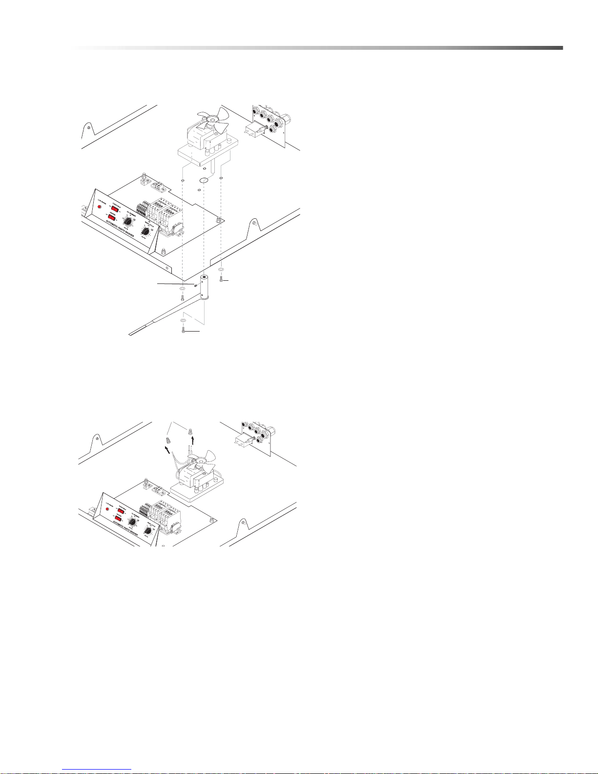
5. Loosen the retaining screw to remove th e tor q ue
Power Leads
Adjusting Bolt
Retaining
Screw
Motor
Mounting
Screws
arm assembly from the drive shaft (use a 1/8” allen
wrench).
Maintenance
6. Remove the four turntable mounting screws.
7. Close the lid.
8. Disconnect the power leads from the motor, then
remove the motor from the lid.
9. Install the new motor. Installation is the reverse
of removal.
Cuda 2412 Operator’s Manual 8.914-384.0 - V
23
Page 24

Maintenance
None
Power
ON
Power
OFF
Power
OFF
Power
OFF
Measure Voltage Across
L1 and N Terminals on
Junction Box
Electrical Panel is OK,
Check Main Power
Disconnect
Visibly Inspect Heater
Relay
Heater Relay is Blown;
Replace the Relay
Visibly Inspect Pump
Relay
Pump Relay is Blown;
Replace the Relay
Check the Blue and
Grey Terminal Blocks
for Loose Connections
Tighten Loose
Connections
Electrical Panel is
OK, Refer to Testing
Individual Components
110 to 120V
OK
OK
OK
Black or
Deformed
Black or
Deformed
Loose
WARNING
KEEP WATER
SPRAY AWAY FROM
ELECTRICAL WIRING.
Troubleshooting
T roubleshooting the Electrical System
To troubleshoot the electrical system use the following
diagrams to eliminate the possibility of a blown fuse or
a bad connection, then refer to Testing Individual
Components to determine which component is caus ing
the problem.
WARNING: Keep water away from
electric wiring or fatal electric
shock may result
• Electrical troubleshooting should be performed
by qualified personnel only.
• Avoid contact with power leads, terminals, and
fuses when power is connected.
• Disconnect power to machine before removing
fuses or other electrical components.
T roubleshooting the Electrical Panel
24
Cuda 2412 Operator’s Manual 8.914-384.0 - V
Page 25
Maintenance
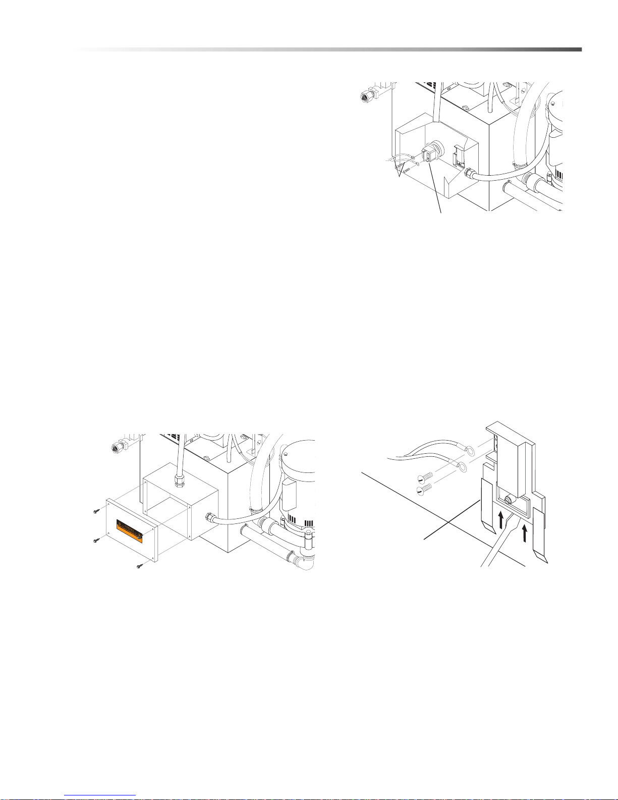
Heating
Power
Leads
Mounting
Bracket
Testing Individual Components
NOTE: The following troubleshooting procedures
require the use of a volt/ohm meter. If you are not
familiar with using a volt/ohm meter do not attempt to
perform the following troubleshooting procedures. If
you need assistance please contact your dealer.
Wash Cycle Timers
1. Disconnect power to the machine.
2. Disconnect all wires and remove the timer from the
control panel and (See Timers and Switches on
the Control Panel).
3. With the timer in the OFF position, test for continuity using an ohm meter.
If there is continuity the timer is no longer functional; replace the timer.
4. With the timer in the ON position, test for continuity
using an ohm meter.
If there is not continuity the timer is no longer functional; replace the timer.
Heating Element
1. Disconnect power to the machine.
2. Remove the rear panel from the machine (four
screws; use a 5/16” wrench or socket).
3. Detach the power leads from the heating element.
Element
4. Use an ohm meter to measure the resistance of
the heating element. The resistance should be
approximately 10 Ohms if not, replace the heating
element (See Heating Element).
Thermostat
1. Disconnect power to the machine.
2. Remove the rear panel from the machine (ten
screws; use a 5/16” wrench or socket ).
3. Detach the power leads from the thermostat.
4. Using a large flat-head screwdriver, pry the thermostat out of the mounting bracket, then remove it
Cuda 2412 Operator’s Manual 8.914-384.0 - V
Screwdriver
from the machine.
5. Set the thermostat to 120°F, warm it to just above
120°F, then test for continuity.
If there is continuity the thermostat is no longer
functional; replace the thermostat.
6. Allow the thermostat to cool to room temperature,
then test for continuity.
If there is not continuity the thermostat is no longer
functional; replace the thermostat.
25
Page 26
Maintenance
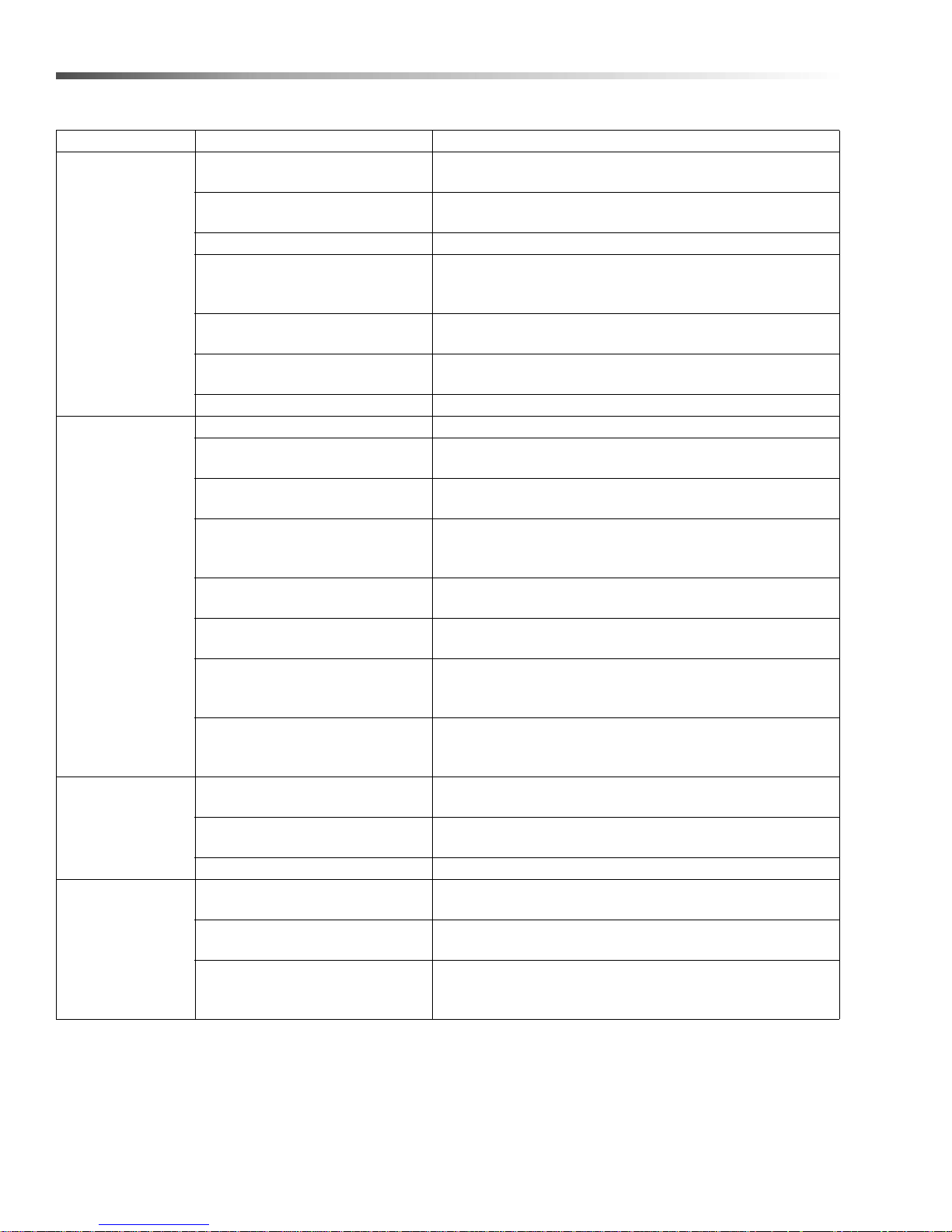
PROBLEM POSSIBLE CAUSE SOLUTION
Verify that the turntable switch is ON
(See Turntable Switch).
Check the position of parts on turntable; position parts to
allow flow of cleaning solution around and between them.
Check spray nozzles for obstructions and alignment; clean
and align if necessary
(See Cleaning and Aligning the Spray Nozzles).
Add 1-2 scoops of detergent and observe cleaning performance; add 1-2 scoops more if necessary. Measure pH.
See wash solution is not heating
Check the water level in the sump; add water
if necessary (See Low Water Shut-Off).
Check thermostat setting; set to 180°
(See Adjusting the Thermostat).
Check for debris buildup around heating
element; clean out if necessary
(See Cleaning out the Sump).
Contact a licensed electrician to verify that the
incoming line voltage meets requirements.
Test the heater timer; replace if necessary
(See Wash Cycle and Heater Timers).
Test the thermostat; replace if necessary
(See Single Phase Thermostat, or
contact dealer to test a three-phase thermostat).
Test the heating element; replace if necessary
(See Single Heating Element, or contact dealer to test a
three-phase heating element).
Bring water up to correct temperature
Do not place oil pan or transmission pan into machine
without pouring oil out of it.
Change sump water and recharge with fresh detergent
and vapor corrosion inhibitor.
Use a water softener and/or change your sump water
more frequently.
Turn heat down to approximately 140°.
POOR
CLEANING
PERFORMANCE
WASH
SOLUTION
NOT HEATING
FOAMING
WHITE POWDER
ON PARTS
Turntable switch is OFF
Parts are obstructing each other
Low water level in sump Check sump water level; add water if necessary.
Clogged or improperly aligned
spray nozzles
Low detergent concentration 10-
11 pH
Wash solution is not properly
heated
Pump is not operating properly See pump does not operate properly.
Blown fuse Refer to Troubleshooting the Electrical System .
Low water level in sump
Thermostat is incorrectly set
Excess debris is built up around
heating element
Line voltage is too low
Failed heater timer
Failed thermostat
Failed heating element
Machine operating with cold
water
Grease, high detergent motor
oils, transmission oil, gear lubes
Not enough detergent Add more detergent, check pH level. Use de-foamer.
Solution is old
Water hardness and TDS (totally
dissolved solids)
Large parts can dry before
solutions runs off, leaving
powdery residue
26
Cuda 2412 Operator’s Manual 8.914-384.0 - V
Page 27
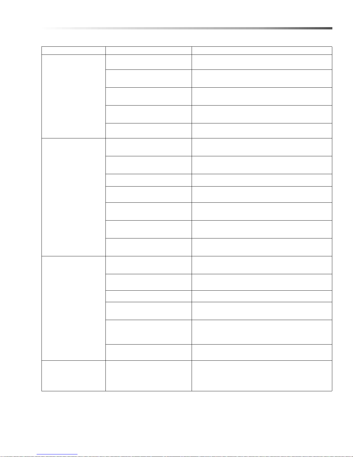
PROBLEM POSSIBLE CAUSE SOLUTION
Verify that no service is being performed on the
machine, then turn the main power disconnect on.
Check the door latch and door safety switch; adjust if
necessary (See Adjusting the Safety Switch).
Test the door closure safety switch; replace if
necessary (See Door Safety Switch).
Test the wash cycle timer; replace if necessary (See
Wash Cycle, Heater and Skimmer Timers).
See pump does not operate properly section.
Ensure that the turntable switch is in the on
position (See Turntable Switch).
MACHINE FAILS TO
START WHEN
"WASHING PARTS"
PROCEDURE IS
FOLLOWED
Main power disconnect is off
Door is not closing properly
Failed door safety switch
Failed washer cycle timer
Pump is not operating
properly
Turntable switch is OFF
Maintenance
TURNTABLE DOES
NOT OPERATE
PROPERLY
PUMP DOES NOT
OPERATE PROPERLY
Parts are obstructing
turntable rotation
Worn thrust bearing Inspect the thrust bearing; replace if necessary
Torque limiter improperly set
Failed wash cycle timer
Failed start capacitor
Failed turntable motor
Low water level in sump
Pump intake is plugged
Pump overload relay is tripped Reset the motor overload relay.
Blown fuse
Line voltage is too low
Check for parts obstructing rotation of the
turntable; rearrange if necessary.
Verify the setting on the torque limiter; adjust if
necessary
Test the wash cycle timer; replace if necessary (See
Wash Cycle, Heater, and Skimmer Timers).
Test the start capacitor; replace if necessary
(See Start Capacitor).
Contact a licensed electrician to test the motor;
replace if necessary (SeeTurntable Motor).
Check the water level in the sump; add water
if necessary (See Low Water Shut-Off System).
Check pump intake for obstructions; clean out if
necessary.
Check electrical panel for a blown fuse; replace if
necessary.
Contact a licensed electrician to verify that
the incoming line voltage meets requirements
as specified on the machine ID tag.
Pump is failed
MACHINE RUSTING
INTERIOR
Steam condensing on inside of a
lid
Cuda 2412 Operator’s Manual 8.914-384.0 - V
Contact a licensed electrician to test the pump;
replace if necessary.
Leave lid open during idle periods.
Check soap concentration.
27
Page 28

Notes
28
Cuda 2412 Operator’s Manual 8.914-384.0 - V
Page 29

Parts
Parts
1.043-356.0, 1.043-379.0, 1.043-357.0,
1.043-536.0, 1.043-537.0, 1.043-538.0
CUDA H2O-2412
Cuda 2412 Operator’s Manual 8.914-384.0 - V
29
Page 30
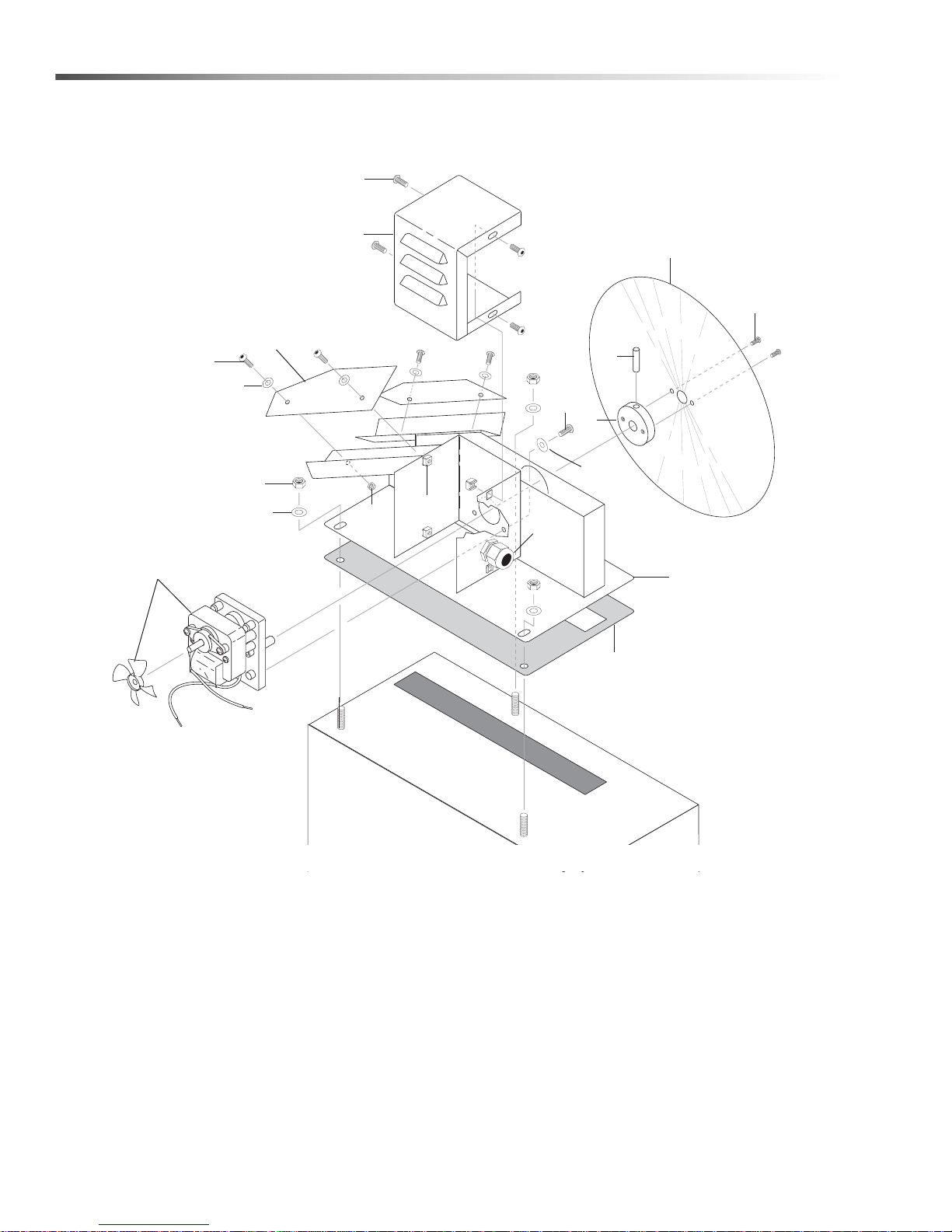
Oil Skimmer
10
5
1
4
2
1
7
8
11
12
9
6
15
17
1
16
14
13
3
30
Cuda 2412 Operator’s Manual 8.914-384.0 - V
Page 31
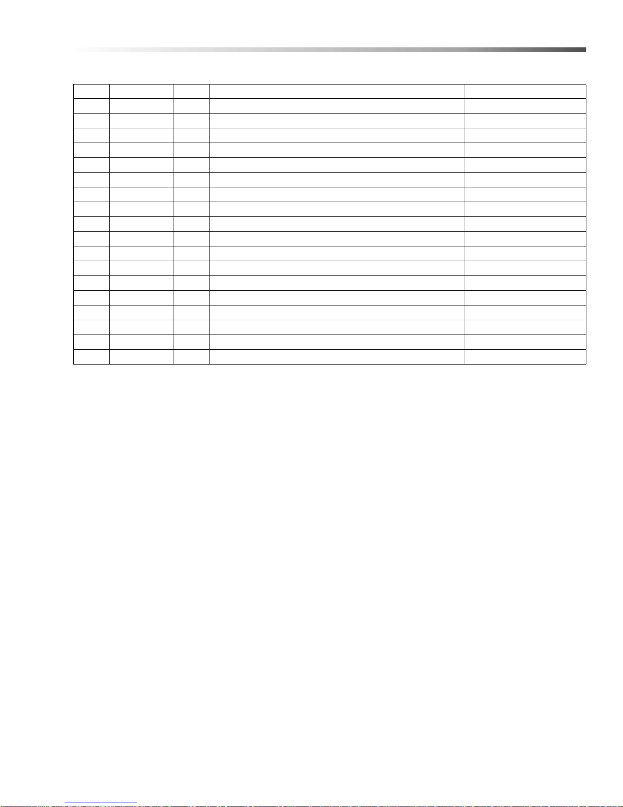
Oil Skimmer
REF PART NO. QTY DESCRIPTION NOTES
1 8.718-810.0 11 SCREW, 10/32" X 1/2" WHIZ LOC FLANGE
2 8.913-733.0 1 COVER, MOTOR, DISC SKIMMER SS
3 8.718-968.0 4 WASHER #10 FLAT ZINC PLT
4 9.804-102.0 2 BLADE, WIPER, DISC SKIMMER SS
5 9.802-773.0 3 NUT, 5/16 ESNA
6 8.918-672.0 1 DISC, SKIMMER SS
7 9.802-791.0 4 NUT, CAGE, 10/32" X 16 GA.
8 9.802-514.0 1 STRAIN RELIEF, STRT, LQ TITE
9 9.804-564.0 2 SCREW, 6-22 X 12
10 8.904-676.0 1 MOTOR, DISC SKIMMER
11 8.719.987.0 1 HUB, DISC MOUNT, DISC SKIMMER
12 8.719-068.0 1 PIN, ROLL 1/8" X 1" STEEL
13 9.804-137.0 1 GASKET, SKIMMER BASE
14 9.802-802.0 3 WASHER, 1/4 FLAT
15 8.913-732.0 1 OIL SKIMMER, SMALL
- 8.922-839.0 1 WLMT, OIL SKIMMER, SMALL, SS
16 8.718-568.0 3 WASHER, 1/4" SEALING
17 9.804-567.0 4 NUT, 10/32 ESNA
31Cuda 2412 Operator’s Manual 8.914-384.0 - V
Page 32
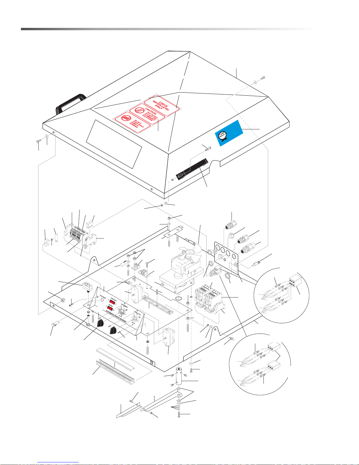
115V Electrical Panel
A
TTENTION
USE ON
L
Y CUDA APPR
O
VED
DET
ERGENT
S
T
O EXTEND
LABOR
WARRANT
Y
T
O 1-YEAR!
MIX DETERGEN
TS
1 LB
(1/2 K
G) PER
5-GALL
ONS (1
5 LITERS) OF
W
A
TER
For CU
DA App
r
o
ved Dete
r
g
ents
visit
http://w
w
w
.cudausa.com
or
call 888-31
9-0
882
9.807
-
513
.
0
90-DA
Y
LABOR
W
A
R
R
A
N
TY
EXT
ENDS TO 1-YEAR
WITH EXC
LU
SIVE USE OF
CU
DA DETE
RGEN
T
S
LIMIT
E
D
62
6
28
9
31
13
7
42
41
43
45
35
10
63
39
38
68
33
36
37
42
49
56
15, 30
65
57
64
60
62
62
37
14
36
28
34
11
12
12
51
50
6146
49
48
53
52
47
36
59
66
5
40
2
22
27
4
1
24
29
58
26
16
17, 20
8
21
23
40
44
19
32
72
18
25
Oil Skimmer
Auto Fill
Option
54
18
69
67
55
24
70
71
Timer
Option
32
Cuda 2412 Operator’s Manual 8.914-384.0 - V
Page 33
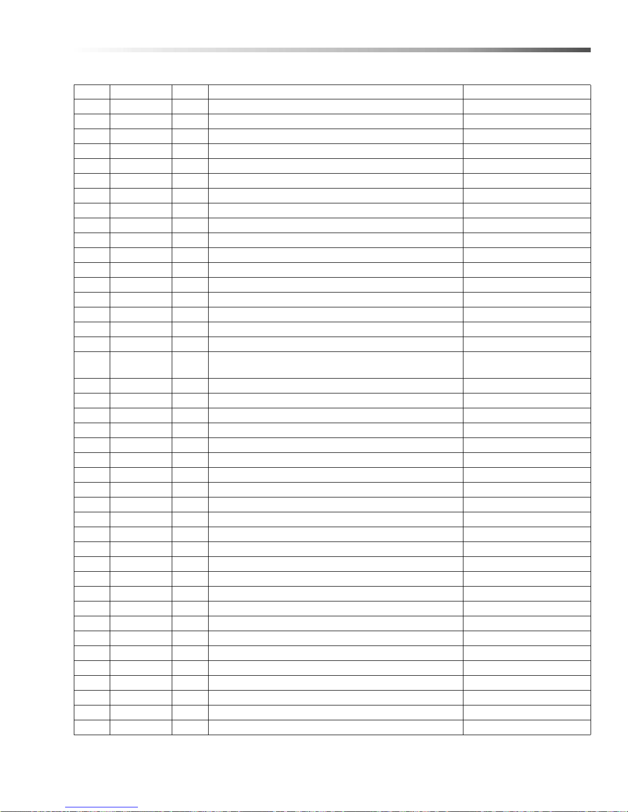
115V Electrical Panel
REF PART NO. QTY DESCRIPTION NOTES
1 8.714-820.0 1 LABEL, CONTROL H20-2412, SC-2412D 115V
2 9.804-510.0 2 SWITCH, LID/DOOR, 15 AMP, NON ENCLOSED
3 8.713-328.0 2 SWITCH-LIGHTED ROCKER SKIMMER/ TT ON/OFF
4 8.716-408.0 1 LIGHT, INDICATOR AMBER 120V
5 8.713-086.0 1 GROUND-LUG 2 HOLE ALUM
6 8.714-164.0 1 TERMINAL BLOCK - 2 POSITION (SURFACE) BL-BL
7 8.756-487.0 1 TIMER, 15 MIN, SPRING WOUND
8 8.753-367.0 1 RELAY, SPDT
9 8.753-368.0 1 RELAY BASE
10 8.713-315.0 1 SWITCH-MERCURY TILT
11 8.713-603.0 2 CONNECTOR, ELECTRICAL 3 PIN MALE
12 8.713-604.0 6 CONNECTOR, ELEC PIN FEM
13 8.750-866.0 1 CONTACTOR, 3 POLE 9 AMP (PUMP)
- 8.750-869.0 1 S CONTACT, NC AUX, FRONT MNT NOT SHOWN
14 8.750-864.0 1 CONTACTOR, 3 POLE 6 AMP (HEATER)
15 8.716-224.0 1 HOLDER, FUSE BLOCK PANEL MT
16 8.716-398.0 3 TERMINAL BLOCK, BLUE, ENTRELEC, 125116-01
17 8.716-396.0 3
18 8.716-399.0 2 END COVER, ENTRELEC, GRAY 11836816 P-ON
19 9.800-040.0 1 LABEL, GRND SYMBOL
20 8.755-017.0 1 TERMINAL BLOCK JUMPER, 3 POLE
21 8.716-599.0 1 TERMINAL GRND, GREEN W/YELLOW
22 8.718-936.0 3 SCREW, #8 X 1/2", PHILLIPS
23 8.718-937.0 2 SCREW, #8 X 3/4" PHILLIPS
24 8.718-733.0 4 SCREW, 6/32" X 5/8", RND, HB
25 8.716-375.0 2 TERMINAL, RING TONQUE
26 9.802-784.0 1 NUT, 6-32 KEPS
27 9.802-457.0 7" DIN RAIL, 35MM
28 9.804-595.0 2 END BRACKET, ENTRELEC
29 8.913-729.0 1 CONTROL PANEL
30 8.714-836.0 1 FUSE, 3 AMP
31 8.713-316.0 1 CLIP, MOUNTING (FOR MERC. TILT SW)
32 8.713-105.0 1 SWITCH BOOT, THREADED
33 8.913-711.0 1 LID COVER 2412
34 8.913-721.0 1 LID INNER LID 2412
35 9.804-207.0 2 BALL STUD, 5/16"-18 UNC, 10MM 2A STUD
36 9.718-980.0 7 WASHER, 5/16" FLAT, SAE
- 9.802-805.0 7 WASHER, 5/16" FLAT, SAE, SS
39 9.804-203.0 2 HANDLE, DOOR/STRAINER
40 9.802-793.0 4 NUT, CAGE, 1/4" X 16 GA
41 9.802-700.0 4 BOLT, 1/4" X 3/4", NC HH
42 9.802-802.0 6 WASHER, 1/4", FLAT, SAE
TERMINAL BLOCK, ENTRELEC,
GRAY 115 -11 6-07 M4/6
33Cuda 2412 Operator’s Manual 8.914-384.0 - V
Page 34
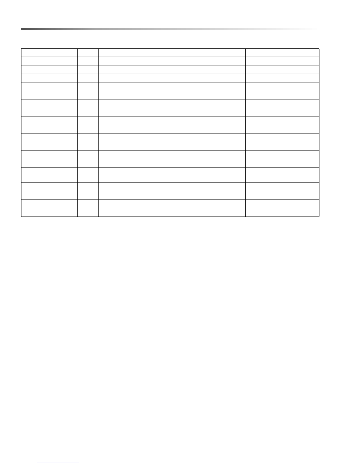
115V Electrical Panel
REF PART NO. QTY DESCRIPTION NOTES
43 8.714-379.0 1 GEARMOTOR, AC6 RPM 120V, 1/2" SS SHAFT
44 9.804-247.0 1 GASKET, GEARMOTOR PAPER FIBERFLEX
45 8.714-380.0 1 TORQUE, HUB OUTLAW
- 8.923-359.0 1 TORQUE, HUB, SS
46 8.913-712.0 1 TORQUE ARM
- 8.923-024.0 1 ARM, TORQUE, ROTATION AR M
47 8.913-713.0 1 TIP TORQUE, ROTATION ARM
- 8.923-023.0 1 TIP TORQUE, ROTATION ARM, SS
48 9.802-700.0 1 BOLT, 1/4" X 3/4", NF HH
- 8.718-603.0 1 BOLT, 1/4"-20 X 3/4", HH SS
49 9.802-773.0 3 NUT, 1/4" ESNA NC
- 9 .8 02 - 774. 0 3 NUT, 1/4" ESNA NC, SS
50 8.714-213.0 1 BOLT, 5/16" X 2" NF HH
51 9.804-238.0 3
52 8.718-810.0 4 SCREW, 10-32" X 1/2" WHIZ LOC FLANGE
- 8.718-813.0 4 SCREW, 10-32 X 1/2" BH SOC,SS
53 8.718-568.0 4 WASHER, 1/4" FLAT SS SEALING RUB
54 9.802-105.0 2 PLUG, 7/8" HOLE
WASHER, BELLEVILLE (DISC SPRING) .
317D X .625 OD, .047" THK
34
Cuda 2412 Operator’s Manual 8.914-384.0 - V
Page 35
115V Electrical Panel
REF PART NO. QTY DESCRIPTION NOTES
55 8.756-488.0 1 TIMER, 30 MIN, SPRING WOUND
56 9.802-525.0 1 LOCKNUT, 1/2" 8463
57 8.716-547.0 1 CONNECTOR, 1/2" L/T STRAIGHT
58 8.913-749.0 1 LID, HINGE STOP
59 8.725-303.0 3 CAPSCREW, 1/4-28 X 5/8"
60 9.804-297.0 1 LABEL, HOUR METER
61 9.804-242.0 1
62 9.802-775.0 2 NUT, 1/4" FLANGE, NC
63 9.804-224.0 12
64 9.802-518.0 1 STRAIN RELIEF, LT, STR,3/4" NPT .49-.71D
65 9.802-515.0 1 STRAIN RELIEF LQ TIT E
66 9.802-748.0 1 SCREW 6/32" X 3/8" RND
67 8.753-351.0 12" CHANNEL 1" W/COVER
68 9.807-513.0 1 LABEL, CUDA APPROVED DETERGENTS
69 8.716-400.0 1 END COVER BLUE
70 8.713-768.0 6 CONNECTOR, ELECTRICAL PIN MALE
71 8.713-731.0 1 CONNECTOR, ELECTRICAL PIN MALE
72 8.756-586.0 2 KNOB, TIMER, SPRING WOUND
WASHER, FLAT BRONZE, 3/8"ID X 3/4" OD X 1/16"
THK THRUST BEARING
DECAL, CAUTION, CHECK WATER LEVELS,
ALL MODELS
35Cuda 2412 Operator’s Manual 8.914-384.0 - V
Page 36
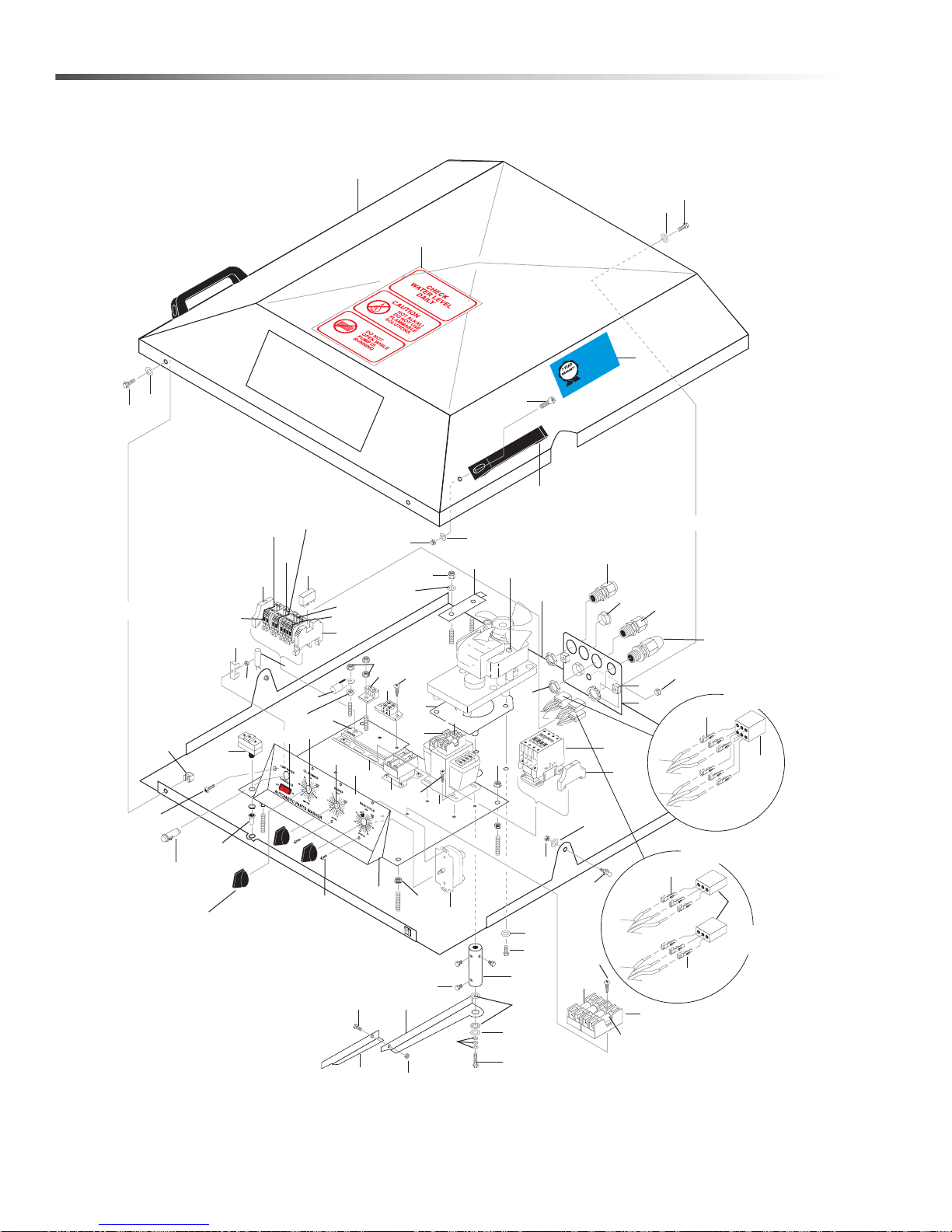
208V, 230V Electrical Panel
90-D
A
Y
L
A
BOR W
ARRANT
Y
EXTENDS TO 1-YEAR
WITH EXCLUSIVE
USE OF
CUDA DETE
RG
ENT
S
LI
M
ITED
16
9
62
30
3
53
70
36
66
67
7
33
39
40
35
4
52
62
69
21
22
5
6
28
26
31
8
68
42
43
56
10
19
58
17, 20
65
49
75
38
76
42
41
54
60
57
34
37
14
28
19
31
61
12
11
12
45
23
71
31
51
50
46
48
47
49
62
29
1
24
27
2
40
25
44
23
41
42
73
59
32
77
72
63
13
64
Oil Skimmer
Auto Fill
Option
Timer
Option
15
18
74
18
62
55
TTENTION
A
USE ON
DETERGENT
LABO
MIX
5-GAL
For CU
VED
O
R
A APP
D
TO EXTEND
O 1-YEAR!
PER
T
S
Y CU
L
KG)
TER
A
1/2
W
B (
ARRANTY
S 1 L
W
ents visit
r
rg
R
LITERS) OF
13.0
NS (15
DETERGENT
07-5
ved Dete
LO
o
9.8
r
.cudausa.com o
w
A App
w
D
call 888-319-0882
http://w
36
Cuda 2412 Operator’s Manual 8.914-384.0 - V
Page 37
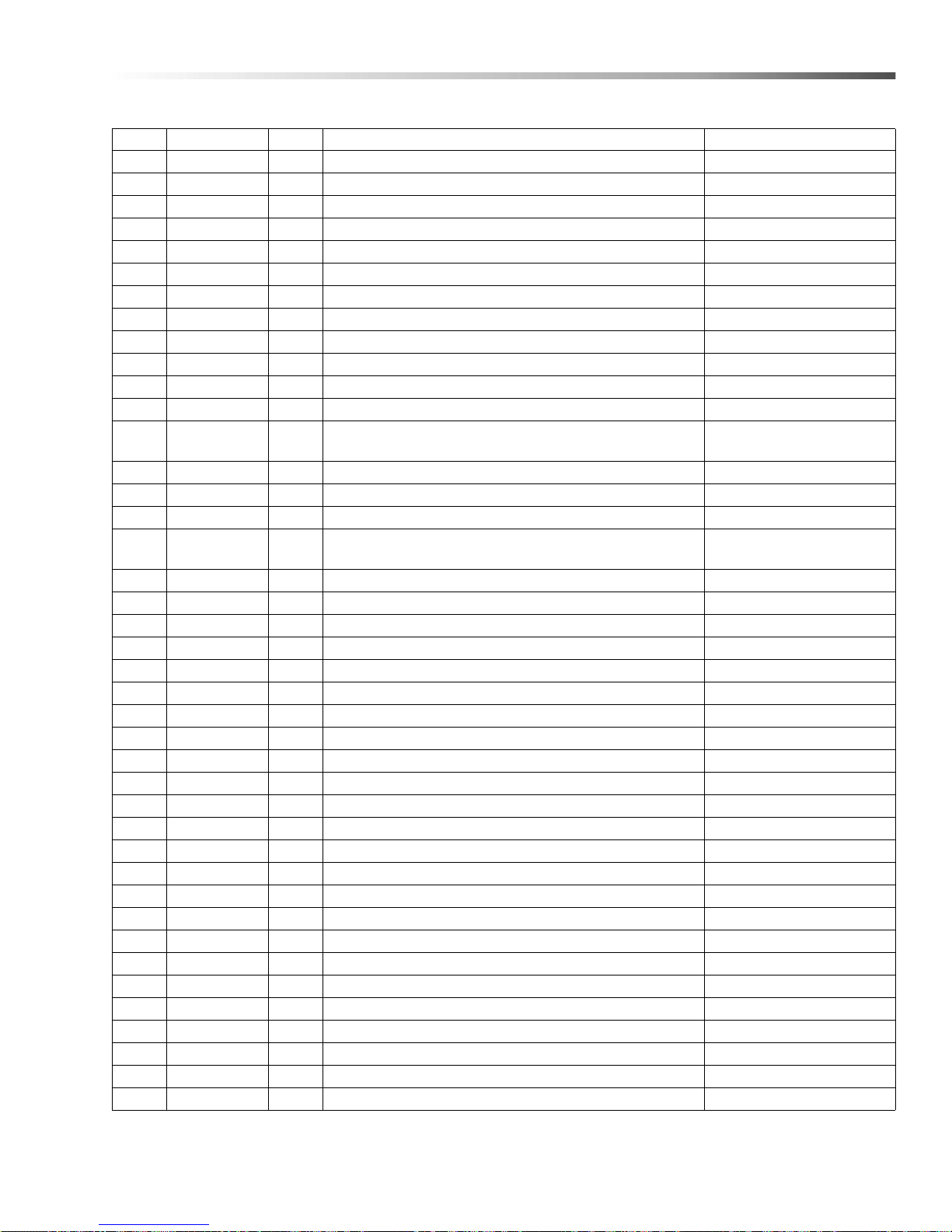
208V, 230V Electrical Panel
REF PART NO. QTY DESCRIPTION NOTES
1 8.714-821.0 1 LABEL, CONTROL, H2O-2412, 230V
2 9.804-510.0 1 SWITCH, LID/DOOR, 15 AMP NON ENCLOSED
3 8.713-328.0 1 SWITCH, LIGHTED ROCKER SKIMMER/TT ON/OFF
4 8.716-408.0 1 LIGHT, INDICATOR AMBER 120V
5 8.713-086.0 1 GROUND, LUG 2 HOLE ALUM
6 8.714-164.0 1 TERMINAL BLOCK, 2 POS (SURFACE) BL-BL
7 8.756-489.0 1 TIMER, 60 MIN, SPRING WOUND
8 8.753-367.0 1 RELAY, SPDT
9 8.753-368.0 1 RELAY, BASE
10 8.713-315.0 1 SWITCH-MERCURY TILT
11 8.713-603.0 2 CONNECTOR, ELECTRICAL 3 PIN MALE
12 8.713-604.0 6 CONNECTOR, ELECTRICAL PIN FEM
13 8.714-290.0 1
14 8.750-866.0 1 CONTACTOR, 3 POLE, 9 AMP
15 8.714-839.0 1 PLUG, PLASTIC BLACK 1/2"
16 8.716-398.0 3 TERMINAL BLOCK, BLUE ENTRELEC 125116-01
17 8.716-396.0 3
18 8.716-399.0 2 END COVER, ENTRELEC, 11836816 P-ON GRAY
19 9.802-776.0 6 NUT, 5/16" ESNA NC
20 8.755-017.0 1 TERMINAL BLOCK JUMPER, 3 POLE
21 8.716-599.0 2 TERMINAL, GROUND, GREEN/YELLOW
22 8.718-936.0 11 SCREW, #8 X 1/2", PHILLIPS
23 8.718-937.0 6 SCREW, #8 X 3/4" PHILLIPS
24 8.718-733.0 6 SCREW, 6/32"X5/8", RND HB MCH
25 9.800-040.0 1 LABEL, GROUND SYMBOL
26 9.802-784.0 1 NUT, 6-32 KEPS
27 9.802-457.0 7" DIN RAIL, 35MM
28 9.804-595.0 2 END BRACKET, ENTRELEC
29 8.941-092.0 1 CONTROL PANEL
30 8.713-316.0 1 CLIP, MOUNTING
31 8.718-980.0 7 WASHER, 5/16" FLAT
- 9.802-805.0 7 WASHER, 5/16" FLAT, SAE, SS
32 8.713-105.0 1 SWITCH BOOT, THREADED
33 8.913-711.0 1 LID TOP 2412
34 8.913-721.0 1 LID 2412
35 9.804-207.0 2 BALL STUD 5/16"-18 UNC 10 MM 2A STUD
36 8.713-287.0 2 FUSE, 12 AMP
37 9.802-518.0 1 STRAIN RELIEF, LT, STR, 3/4" NPT .49-.71D
38 8.713-246.0 4 SCREW, 5/16"-18 X 1" SKT HD
39 9.804-203.0 2 HANDLE, DOOR/STRAINER
40 9.802-793.0 4 NUT, CAGE, 1/4" X 16 GA
CONTACTOR, GEN PURPOSE, 2 POLE 230V, 30
AMP
TERMINAL BLOCK, ENTRELEC, GRAY 115-116-07
M4/6
37Cuda 2412 Operator’s Manual 8.914-384.0 - V
Page 38
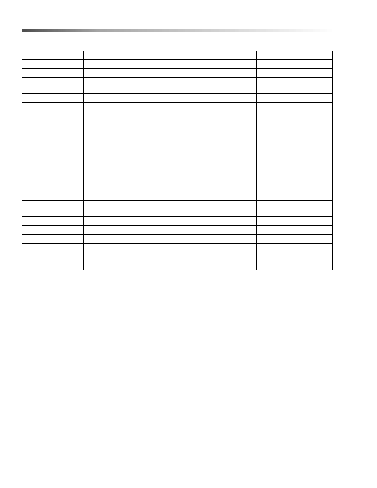
208V, 230V Electrical Panel
REF PART NO. QTY DESCRIPTION NOTES
41 9.802-700.0 4 BOLT, 1/4" X 3/4", NC HH
42 9.802-802.0 6 WASHER, 1/4" FLAT SAE
43 8.714-379.0 1
44 9.804-247.0 1 GASKET, GEARMOTOR PAPER FIBERFLEX
45 8.714-380.0 1 TORQUE HUB, OUTLAW
- 8.923-359.0 1 TORQUE HUB, SS
46 8.913-712.0 1 TORQUE ARM
- 8.923-023.0 1 ARM,TORQUE ROTATION ARM
47 8.913-713.0 1 TIP TORQUE ROTATION ARM
- 8.923-023.0 1 TIP TORQUE ROTATION ARM, SS
48 9.802-700.0 1 BOLT, 1/4" X 3/4", NC HH
- 8.718-603.0 1 BOLT, 1/4-20 X 3/4", HH,SS
49 9.802-773.0 3 NUT, 1/4" ESNA NC
- 9.802-774.0 3 NUT, 1/4" ESNA, NC, SS
50 8.7 14-213.0 1 BOLT, 5/16" X 2", NF HH
51 9.804-238.0 3
52 8.718-810.0 4 SCREW, 10-32" X 1/2" WHIZ LOC FLANGE
- 8.718-813.0 4 SCREW, 10-32" X 1/2" BH SOC, SS
53 8.718-568.0 4 WASHER, 1/4" FLAT SS SEALING RUB
54 9.802-105.0 2 PLUG, 7/8" HOLE
55 8.756-488.0 1 TIMER, 30 MIN, SPRING WOUND
56 9.802-525.0 1 LOCKNUT, 1/2" 8463
GEARMOTOR, AC FRACT 6 RPM 2412 DRIVE 120V
1/2" SS SHAFT
WASHER, BELLEVILLE (DISC SPRING) .317D X
.625 OD .047" THK
38
Cuda 2412 Operator’s Manual 8.914-384.0 - V
Page 39
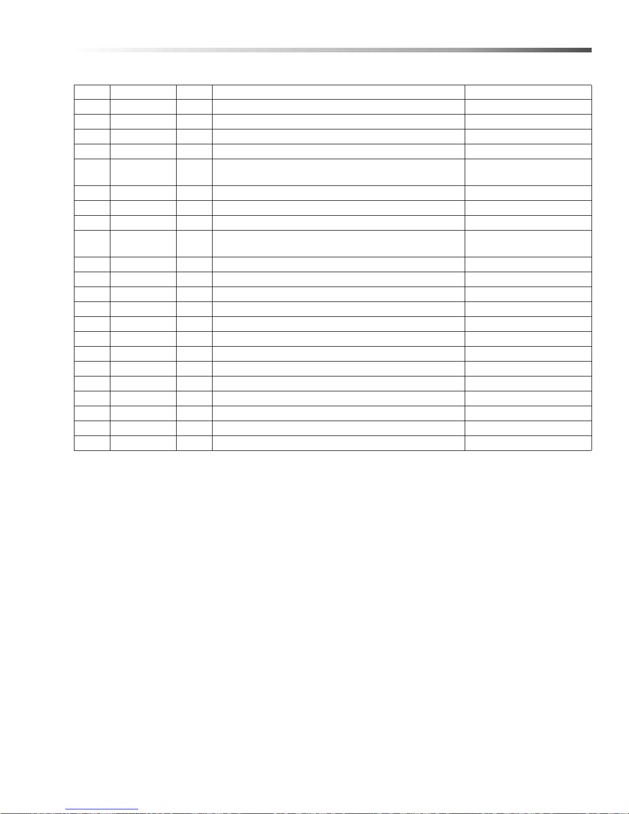
208V, 230V Electrical Panel
REF PART NO. QTY DESCRIPTION NOTES
57 8.7 16-547.0 1 CONNECTOR, 1/2" L/T STRAIGHT
58 8.913-749.0 1 LID, HINGE STOP
59 8.7 25-303.0 3 CAPSCREW, 1/4-28 X 5/8" SS
60 9.804-297.0 1 LABEL, HOUR METER
61 9.804-242.0 2
62 9.802-775.0 12 NUT, 1/4" FLANGE NC
63 8.713-768.0 6 CONNECTOR, ELECTRICAL PIN MALE
64 8.716-375.0 2 TERMINAL, RING TONGUE
65 9.804-224.0 1
66 8.713-290.0 2 FUSE BLOCK (H2PR) 2 POLE
67 8.756-490.0 1 TIMER, 12 HOUR, SPRING WOUND
68 8.716-875.0 1 TRANSFORMER, 200VA, 230-460V/115V
- 8.716-895.0 1 TRANSFORMER, 200VA, 208V
69 8.713-078.0 1 FUSE, 2 AMP FNM-2
70 8.713-286.0 2 FUSE, CLASS 2 AMP
71 8.713-369.0 2 FUSE, 25 AMP
72 8.713-731.0 1 CONNECTOR, ELECL, 6-PIN FEM
73 9.8 02-784.0 1 SCREW, 6/32" X 3/8"
74 8.716-400.0 1 END COVER, BLUE, ENTRELEC
75 9.802-515.0 1 STRAIN RELIEF, STRT, LQ TITE
76 9.807-513.0 1 LABEL, CUDA APPROVED DETERGENTS
77 8.756-586.0 3 KNOB, TIMER, SPRING WOUND
WASHER, FLAT BRONZE, 3/8"ID X 3/4" OD X 1/16"
THK THRUST BEARING
DECAL, CAUTION, CHECK WATER LEVEL, ALL
MODELS
39Cuda 2412 Operator’s Manual 8.914-384.0 - V
Page 40
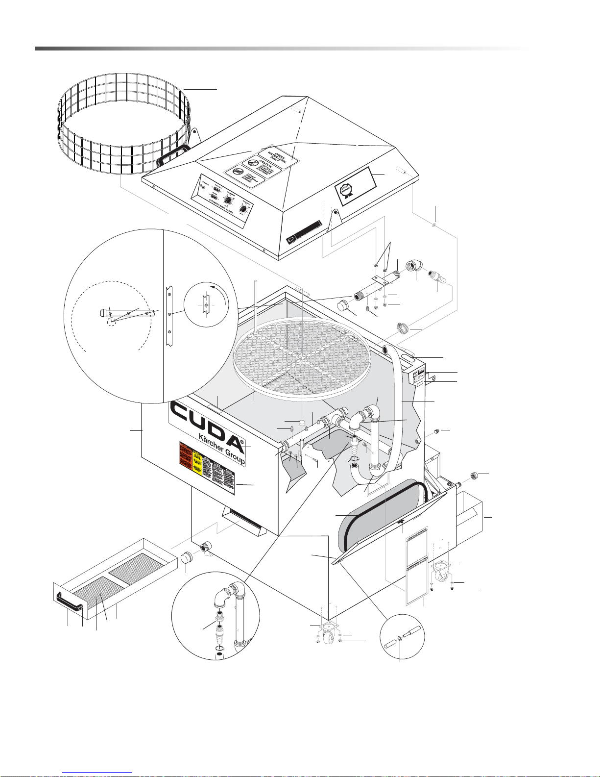
Cuda 2412 Front
O
P
ER
A
T
IN
G
IN
ST
R
U
C
T
IO
N
S
MAIN
T
EN
A
N
C
E
INS
T
R
U
C
T
IONS
KE
E
P
H
A
N
DS C
LE
A
R
W
HEN
C
L
O
S
ING
L
I
D
9
.80
1
-1
2
5
.
0
ATTENTIO
N
U
S
E
O
N
L
Y
C
U
D
A
A
P
P
R
O
V
E
D
D
E
T
E
R
G
E
N
T
S
TO
E
X
T
E
N
D
L
A
B
OR
W
A
R
R
A
N
T
Y
T
O
1
-Y
E
A
R
!
M
I
X
D
E
T
ER
G
EN
TS
1
LB
(
1
/
2
K
G
)
P
ER
5-
G
A
L
L
O
NS
(
15
L
I
TE
R
S
)
O
F
W
A
T
ER
F
or
C
U
DA
A
pp
r
o
v
e
d
D
e
te
r
g
e
n
t
s
v
i
s
i
t
http
:
//
w
w
w.c
ud
a
us
a
.
co
m
o
r
c
a
l
l
8
8
8
-3
1
9
-0
8
8
2
9
.
8
0
7
-5
1
3
.
0
9
0
-
D
A
Y
L
A
B
O
R
W
A
R
RAN
T
Y
E
X
T
E
N
D
S
T
O
1
-
Y
E
A
R
W
I
T
H
E
X
C
L
U
S
I
V
E
U
S
E
O
F
C
U
D
A
D
E
T
E
R
G
E
N
T
S
L
I
MIT
E
D
8
9
4
3
2
1
16
15
6
7
10
25
20
22
21
46
43,44,45
42
47
47
48
23
27
24
30
28
20
32
32
26
14
31
18
13
19
31
14
33
12
17
31
32
36
35
37
5
34
22
Approx. 3°
from center
line of pipe
Align with
the center of
turntable
SIDE
TOP &
BOTTOM
Turntable
Nozzle Alignment
40
39
49
29
51
41
11
50
Stainless
Steel
Option
Only
40
Cuda 2412 Operator’s Manual 8.914-384.0 - V
Page 41
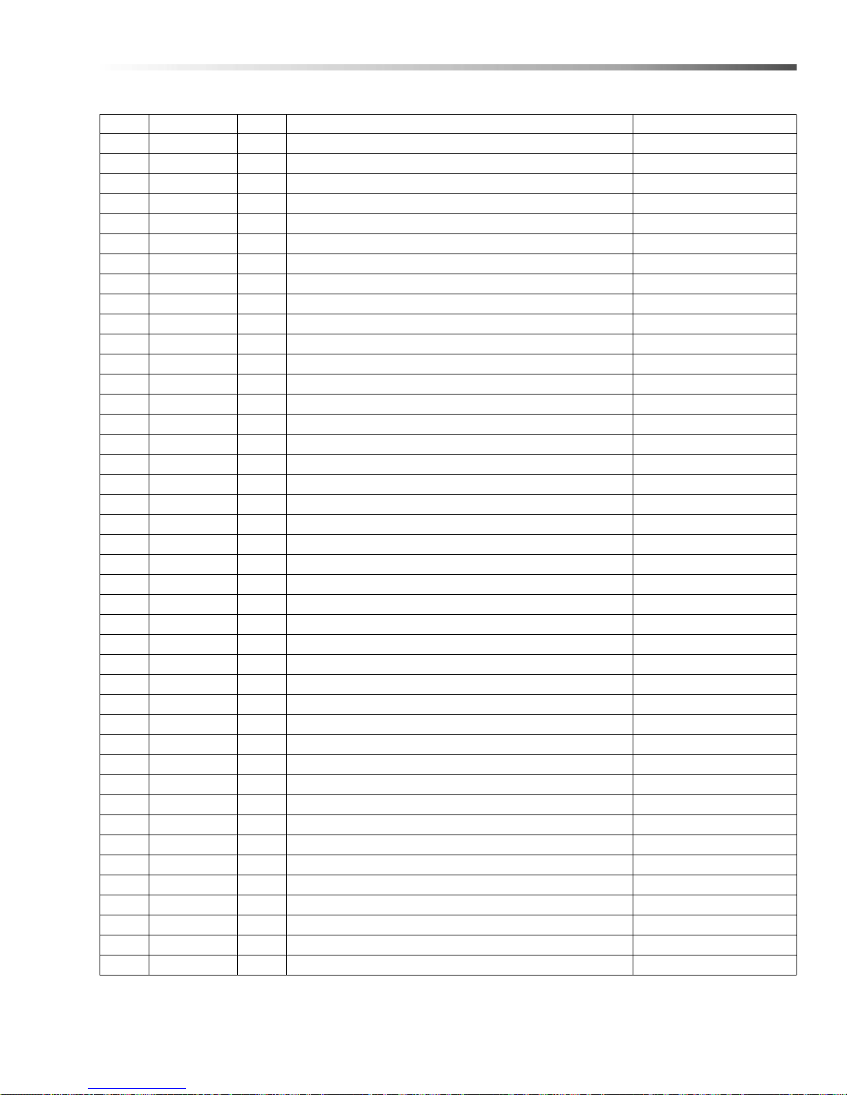
Cuda 2412 Front
REF PART NO. QTY DESCRIPTION NOTES
1 8.913-719.0 1 TANK ASSY 2412
- 8.922-996.0 1 WLMT, TANK, SS
2 8.706-328.0 1 PIPE, PLUG 1/4" GALV.
- 8.753-897-0 1 PLUG, PIPE, 1/4, 304 SS
3 8.706-350.0 1 PIPE, CAP 1/2" GALV.
- 8.753-615.0 1 CAP, 1/2" THREADED, 304 SS
4 8.706-349.0 1 PIPE, CAP 1-1/2" GALV.
- 8.749-821.0 1 PIPE-CAP 1-1/2" STAINLESS STEEL
5 9.802-776.0 2 NUT, 5/16 ESNA
6 8.915-388.0 48" SEAL, BULB TYPE (12G) NITRILE, SIDE PROFILE
7 9.804-185.0 1 LATCH-VISE ACTION SIDE ACC COVER
8 8.711-919.0 2 CASTER, FIXED, 2-1/2" POLYWHEEL
9 8.711-920.0 2 CASTER, SWIVEL, 2-1/2" X 1-1/8" POLYOLEFIN
10 8.713-246.0 2 SCREW, 5/16"-18 X 1" SOCKET HEAD
11 9.804-203.0 1 HANDLE, DOOR/STRAINER
12 8.913-705.0 1 DEBRIS, TRAY ASSY
- 8.922354.0 1 WLMT, DEBRIS TRAY, SS
13 8.922-512.0 1 WLMT, DOOR, SUMP ACCESS, SS
14 8.712-777.0 5 NOZZLE, 50°, #3
- 9.804-196.0 5 NOZZLE, 50°, #3 STAINLESS
15 8.755-292.0 3 NOZZLE, 80°, #3
- 8.714-202.0 3 NOZZLE, 80°, #3, SS
16 8.706-047.0 1 PIPE, BUSHING 1-1/4" TO 1" BLACK
- 8.706-288.0 1 BUSHING 1' X 1/1/4' STAINLESS
17 8.706-081.0 1 CAP, PIPE 1 NPT 150WP NON PL
- 8.753-614.0 1 CAP, 1" THREADED, 304 SS
18 8.706-320.0 1 CAP, 3/4" BLACK PIPE
- 8.749-619.0 1 PIPE CAP 3/4" STAINLESS
19 8.706-188.0 1 ELBOW, 45°, 3/4" BLACK
- 8.754-347.0 1 ELBOW, 45°, 3/4" NPT SS
20 8.706-340.0 2 PIPE, BARBED, MALE NPT 3/4" BLACK
- 9.804-210.0 2 PIPE, BARBED, MALE NPT 3/4" STAINLESS
21 9.802-261.0 24" HOSE, 3/4" PUSH-ON, PER/FT
22 9.803-629.0 2 CLAMP, SCREW, #16
23 8.720-002.0 1 SPRAY PIPE 1" X 10"
- 9.923-239.0 1 SPRAY PIPE 1" X 10", SS
24 8.913-706.0 1 ASSY., UPPER SPRAY BAR
- 9.923-020.0 1 WLMT, UPPER SPRAY BAR, SS
25 8.913-724.0 1 TURNTABLE ASSY
- 9.923-014.0 1 WLMT, TURNTA BLE, SS
26 9.804-259.0 1 THRUST BEARING
27 8.904-660.0 1 DECAL, KEEP HANDS CLEAR WHEN CLOSING LID
41Cuda 2412 Operator’s Manual 8.914-384.0 - V
Page 42
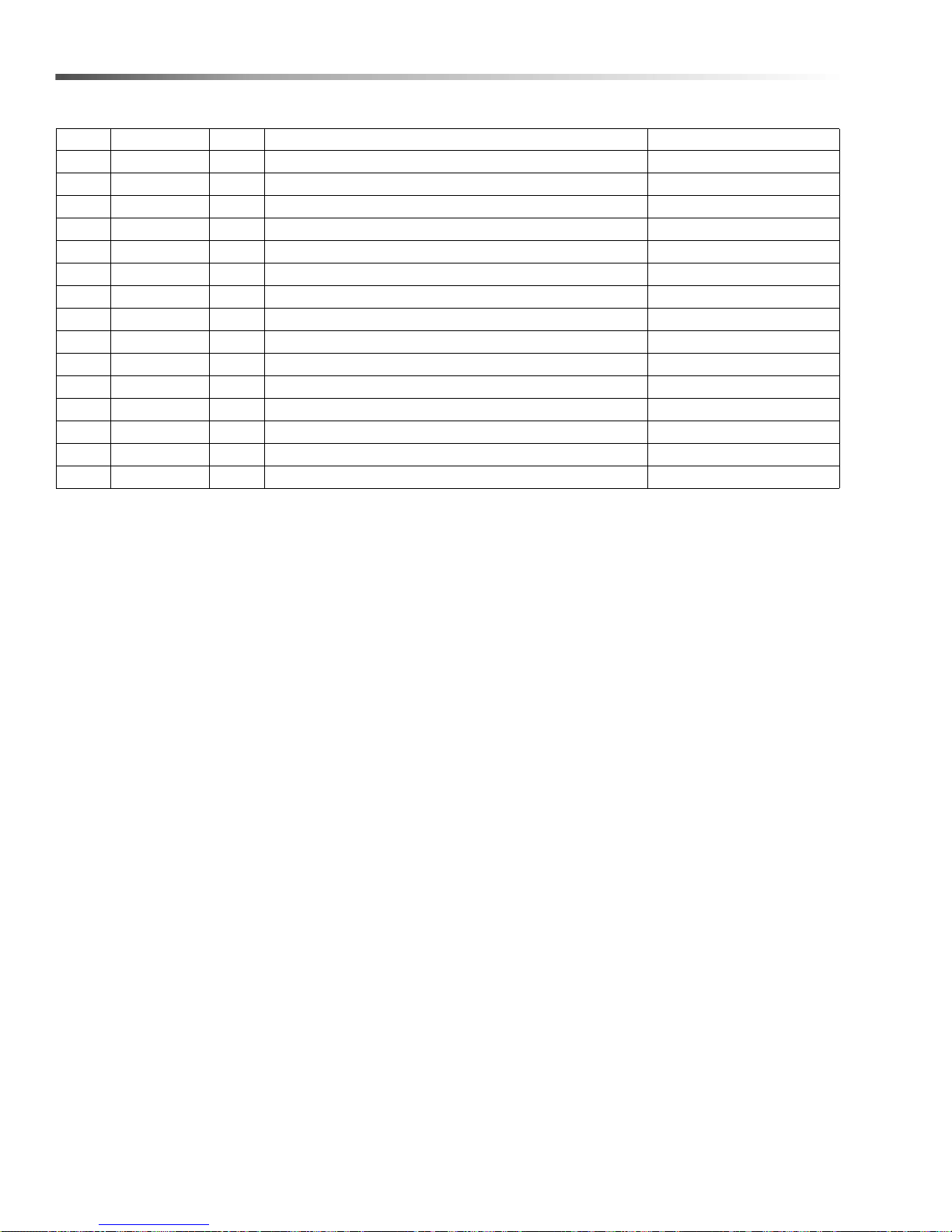
Cuda 2412 Front
REF PART NO. QTY DESCRIPTION NOTES
28 9.804-223.0 1 DECAL, OPER INST, ALL MODELS
29 9.801-126.0 1 LABEL, CUDA 24 X 6
30 8.924-172.0 1 BUCKET, OIL
31 9.802-773.0 18 NUT, 1/4" ESNA, NC
- 9.802-774.0 18 NUT, 1/4" ESNA, NC, SS
32 9.802-802.0 18 WASHER, 1/4" FLAT, SAE
- 8.718-965.0 18 WASHER, 1/4" FLAT, SAE, SS
33 8.705-962.0 1 RING, CONTAINMENT 24"
34 8.718-810.0 3 SCREW, 10/32 X 1/2,WHIZ LOC FLANGE
- 8.718-810.0 3 SCREW, 10/32 X 1/2, BH SOC, SS
35 8.718-568.0 3 WASHER, SEALING
36 9.804-567.0 3 NUT, 10/32 ESNA
37 8.718-980.0 2 WASHER, 5/16" FLAT
38 8.731-254.0 1 PARTS BASKET, SMALL 8 X 8 X 4 NOT SHOWN
39 8.725-296.0 2 WASHER, BULLET HINGE 8MM PIN BRASS
42
Cuda 2412 Operator’s Manual 8.914-384.0 - V
Page 43

Cuda 2412 Front
REF PART NO. QTY DESCRIPTION NOTES
40 8.725-297.0 2 WASHER, BULLET HINGE 6MM PIN BRASS
41 9.802-775.0 2 NUT, 1/4", FLANGE NC
42 8.751-325.0 1 FILTER MEDIOL, 1/4", 2" X 12" X 1"
43 9.800-013.0 1
44 9.800-034.0 1 LABEL, CLEAR LEXAN
45 N/A 1 LABEL, UL/ETL
46 9.804-361.0 1 DECAL, PATENT NUMBER
47 8.706-150.0 3 ELBOW, 1", 150WP, PL
- 8.754-346.0 3 ELBOW, 1", 150WP, PL SS
48 8.706-191.0 1 ELBOW, 1" X 3/4", 90°, GALV
49 9.807-513.0 1 LABEL, CUDA APPROVED DETERGENTS
50 8.754-353.0 1 BUSHING, 1" X 3/4" SS
51 8.900-587.0 1 LABEL, APW WARNING/OPS INST
LABEL, ASSEMBLED USA INTENDED FOR INDOOR
USE.
(STAINLESS STEEL
OPTION ONLY)
43Cuda 2412 Operator’s Manual 8.914-384.0 - V
Page 44
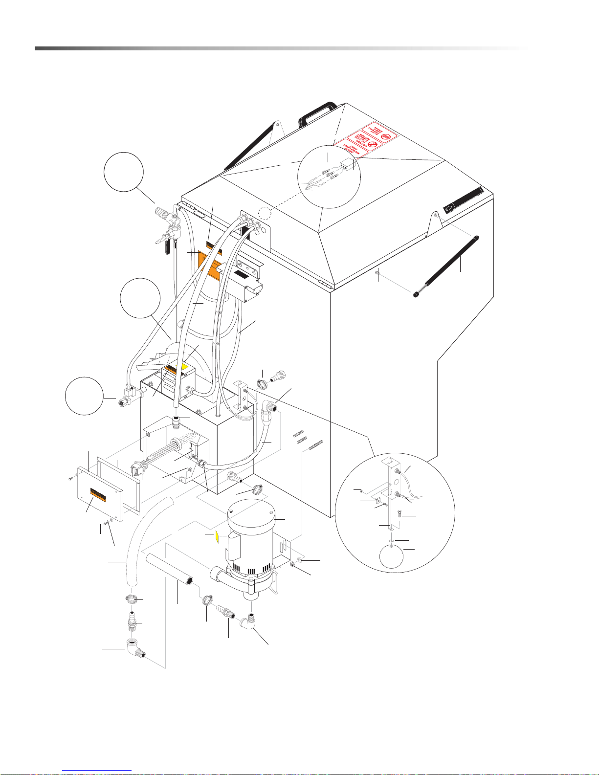
Cuda 2412 Rear
WARNING
HOUR METER
KEEP
DRY
KEEP
DRY
89143840-17
8
5
28
17
18
13
15
12
33
35
10
11
2, 3, 4
1
16
31
32
34
32
34
31
21
5
14
36
37
34
34
29
27
22
41
6
19
See Oil
Skimmer
Assy
See
Auto-Fill
Option *
See Air
Brush
Option
27
24
23
9
39
26
27
25
39
20
38
7
* WARNING: If connnection is made to a potable
water supply, Protect against backflow
44
Cuda 2412 Operator’s Manual 8.914-384.0 - V
Page 45
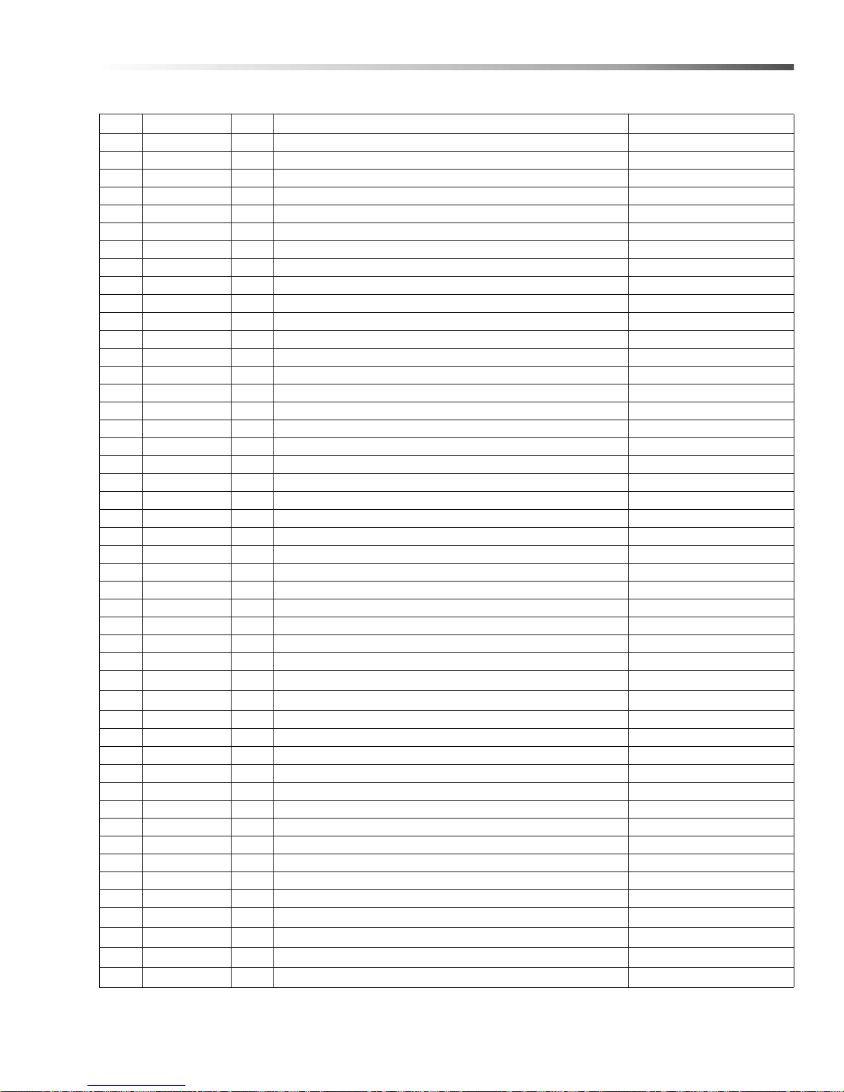
Cuda 2412 Rear
REF PART NO. QTY DESCRIPTION NOTES
1 8.714-540.0 2 GAS SPRING, STRUT 70# ( 4514QF) (115V)
- 8.724-076.0 2 GAS SPRING 90# (7227SA) (230V)
2 9.804-207.0 2 BALL STUD, 5/16"-18 UNC 10MM 2A STUD
3 9.802-776.0 2 NUT, 5/16" ESNA, NC
4 8.718-987.0 2 WASHER, 5/16" FLAT SS SEALING RUB
5 8.71 6-542.0 2 CONNECTOR, 1/2" L/T STRAIGHT, BLACK
6 8.716-011.0 39" CONDUIT, FLEXO 1/2" BLK
7 9.802-802.0 4 WASHER FLAT 1/4"
8 9.802-448.0 36" CONDUIT, WATER TIGHT, FLEX 1/2"
9 9.802-448.0 22" CONDUIT, WATER TIGHT FLEX 1/2"
10 8.714-187.0 1 HEATING ELEMENT,.8KW/120V/1 PH1" NPT, MS 9"L W/SEAL (115V 1 PH)
- 8.712-813.0 1 HEATING ELEMENT, 4.5 KW/230V/1 PH, 1" NPT MS W/SEAL (208V 1 PH, 230V 1 PH)
11 8.713-593.0 1 THERMOSTAT, SNAP DISC 180° F 1 PH
12 9.804-119.0 1 SWITCH, MAGNETIC REED SENSOR NC
13 9.804-118.0 1 SWITCH, MAGNETIC REED SENSOR, NO
14 9.804-120.0 1 MAGNET, REED SENSOR TARGET
15 8.73 1-134.0 1 SCREW, 4-40 X 1/2" SLOTTED P/H M/S ZINC
16 8.718-847.0 1 NUT, 4-40 KEPS, ZINC
17 8.75 4-718.0 1 FLOAT, 2-1/2" BALL STAINLESS
18 8.922-155.0 1 FLOAT ROD SS
19 8.93 0-331.0 1 COVER, HEATER ELEMENT
20 9.80 2-094.0 30" FOAM STRIP 1/8" X 1/2" ADHESIVE BACK
21 9.802-700.0 4 BOLT, 1/4" X 3/4", NC
22 8.71 8-806.0 1 SCREW, 1/4-20 X 1/2", SCHS SS
23 9.802-423.0 60" CORD 16/3
24 9.804-140.0 1 DECAL, WARNING
25 8.713-656.0 1 CONNECTOR, ELECTRICAL, 3 PIN FEMALE
26 8.713-768.0 3 CONNECTOR, ELECTRICAL PIN MALE
27 9.800-016.0 3 LABEL, DISCONNECT POWER SUPPLY
28 8.71 5-398.0 1 PUMP SCOT, 1/2 HP 115/230V 1 PH
- 8.713-359.0 - SEAL KIT
- 8.713-360.0 - O-RING
29 9.80 2-517.0 1 CONNECTOR, 1/2 L/T, 90°, BLACK
30 9.80 2-105.0 1 PLUG, 7/8" HOLE NOT SHOWN
31 8.70 6-196.0 2 ELBOW, 1-1/4", 90° STREET, BLACK
- 8.754-076.0 2 ELBOW, 1-1/4", 90° STREET, S/S
32 8.706-341.0 2 PIPE, BARBED MALE NPT 1-1/4" GALV.
- 9.804-198.0 2 PIPE, BARBED MALE NPT 1-1/4" STAINLESS
33 8.714-828.0 1 HOSE, 1-1/4" X 6-1/2" PRECUT BLACK 200 PSI
34 8.70 9-081.0 4 CLAMP, SCREW, #28
35 9.804-244.0 1 HOSE, 1-1/4" X 14-1/2" PRECUT, 200 PSI
36 9.802-807.0 4 WASHER, 3/8" SAE FLAT
37 9.802-779.0 4 NUT, 3/8" ESNA, NC
38 9.802-793.0 4 NUT, CAGE 1-4" X 16 GA
39 9.804-374.0 2 DECAL, KEEP DRY
40 8.71 2-896.0 1 SCOOP, DETERGENT, WHITE 16 OZ. NOT SHOWN
41 8.921-274.0 1 SPACER, BRAKE LINK, 800
45Cuda 2412 Operator’s Manual 8.914-384.0 - V
Page 46
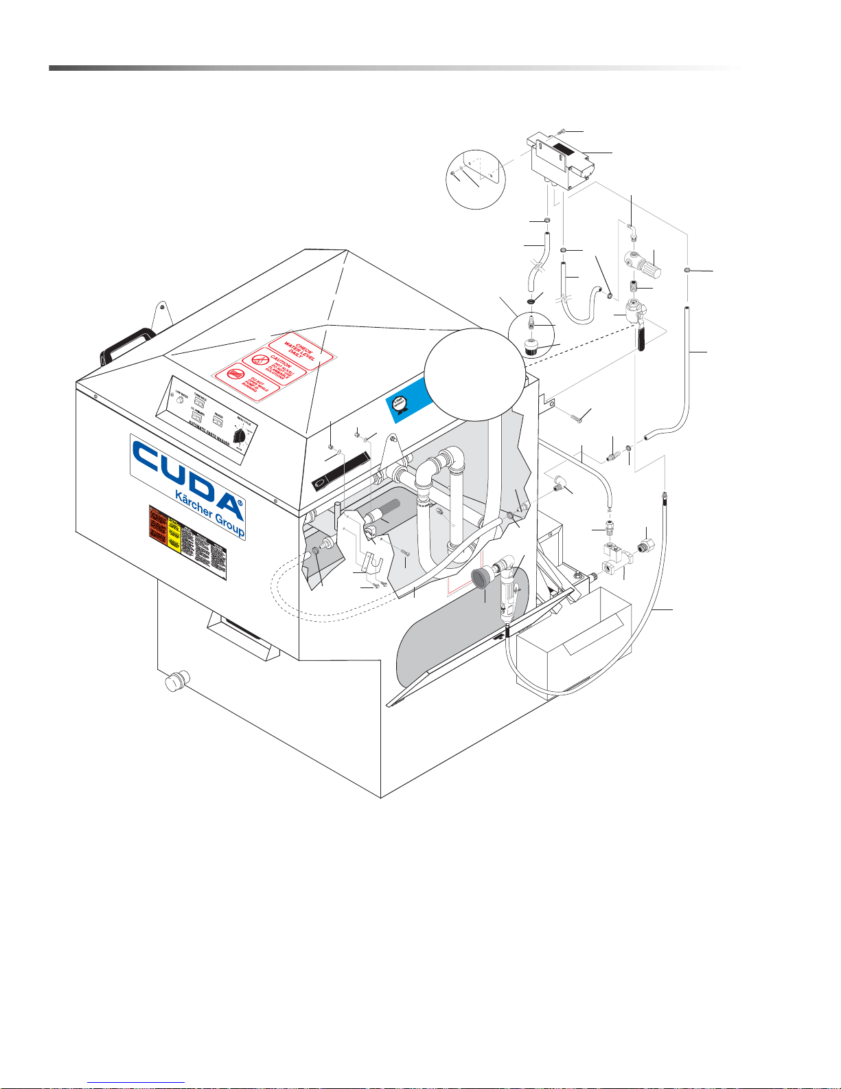
Auto Fill, Detail Brush & Power Brush Options
ATTENTION
USE ON
L
Y CU
D
A APP
R
O
VED
DETERGENTS
T
O EXTEND
LABOR
W
ARRANT
Y
TO 1-YEAR!
MIX DETERG
ENT
S 1
LB
(1/2
KG
) PER
5-GA
LL
ON
S (15 LIT
ERS) OF
WA
TE
R
For CU
D
A Appr
o
ved Dete
r
gen
t
s v
i
s
i
t
http://w
w
w
.cudausa.
com
or
call
888-319-088
2
9.807
-513.
0
90-D
A
Y L
AB
OR
W
A
RRAN
T
Y
E
XTEND
S
TO
1-YEA
R
WITH EX
CLU
SIVE USE OF
CUDA DETER
GEN
T
S
L
I
MIT
E
D
29
28
31
30
1
3
4
5
9
10
18
12
26
14
20
17
36
20
14
24
6
7
12
14
27
16
To Sump
Chamber
27
23
21
25
21
11
13
2
15
2
22
2
19
8
21
Plug (Item 35)
Installed Here
When Power
Brush is Not
Supplied
46
Cuda 2412 Operator’s Manual 8.914-384.0 - V
Page 47
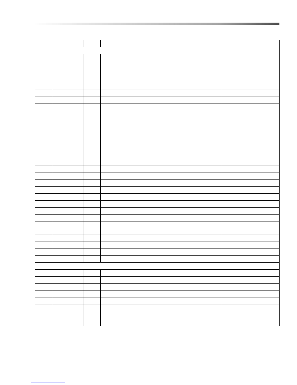
Auto Fill, Detail Brush & Power Brush Options
REF PART NO. QTY DESCRIPTION NOTES
DETAIL & POWER BRUSH KIT (8.725-245.0)
1 8.712-778.0 1 PUMP -AIR DIAPHRAGM
2 8.709-117.0 3 CLAMP, HOSE, UNI .62-.75 ST
3 8.712-810.0 1 REGULATOR -AIR 1/4" NPT
4 9.804-091.0 1 BRUSH -POLYFLOW (FLO-THRU)
5 8.712-815.0 1 CLIP -DETAIL BRUSH
6 8.712-834.0 1 DRILL -PNEUMATIC AIR R-ANGLE
7 8.712-835.0 1 BRUSH -WIRE CUP 2-3/4" DIA., 1/4" STEM
8 8.712-836.0 1
9 8.712-838.0 1 PIPE -BALL VALVE 1/4" 3-WAY
10 9.802-254.0 24" HOSE, 1/4", PUSH-ON, FUEL LINE /FT
11 8.706-161.0 1 ELBOW, 1/4", STREET, 90° GALV
12 8.718-813.0 3 SCREW, 10-32" X 1/2" BH, SOC, SS
13 8.711-785.0 27.5" HOSE, 3/8" PUSH ON, /FT
14 9.804-567.0 5 NUT, 10/32", ESNA
15 8.718-959 .0 2 WASHER, #10 FLAT S/S
16 8.915-637.0 1 BRACKET, POWER BRUSH
17 8.714-007 .0 40" HOSE -1/4" ID X 7/16" OD BUNA TUBING 60 DURO
18 8.706-958.0 1 HOSE BARB, 1/4" BARB X 1/4" PIPE, 90°
19 8.706-941.0 1 HOSE BARB, 1/4" BARB X 1/4" ML PIPE, BRASS
20 8.706-950.0 2 HOSE BARB, 3/8" BARB X 1/4" ML PIPE
21 6.390-126 .0 4 CLAMP, HOSE, .46-.54 ST
22 8.714-255.0 2 SCREW-10-24 X 1/4"SS MS PHIL
23 8.706-777.0 1 NIPPLE, 1/4" CLOSE-P/N-3326-4
24 8.712-808.0 1
25 9.802-103.0 1 BUSHING, SNAP, 5/8"
26 8.711-785.0 18.5" HOSE, 3/8" PUSH-ON, /FT
27 8.718-568.0 3 WASHER, 1/4" FLAT SS
36 8.718-810.0 2 SCREW, 10/32" X 1/2" WHIZ LOC FLANGE
1 8.712-778.0 1 PUMP -AIR DIAPHRAGM
2 8.709-117.0 3 CLAMP, HOSE, UNI .62-.75 ST
3 8.712-810.0 1 REGULATOR -AIR 1/4" NPT
4 9.804-091.0 1 BRUSH -POLYFLOW (FLO-THRU)
5 8.712-815.0 1 CLIP -DETAIL BRUSH
9 8.712-838.0 1 PIPE -BALL VALVE 1/4" 3-WAY
10 9.802-254.0 24" HOSE, 1/4", PUSH-ON, FUEL LINE/FT
11 8.706-161.0 1 ELBOW, 1/4", STREET, 90° GALV
HOSE -ASSEMBLY 1/4" X 60", MPT EA END POWER
BRUSH
FILTER -INLET (MESH BALL 1/4" NPT20 X 20 MESH)
DETAIL PUMP
DETAIL BRUSH KIT (8.725-251.0)
47Cuda 2412 Operator’s Manual 8.914-384.0 - V
Page 48
Auto Fill, Detail Brush & Power Brush Options
REF PART NO. QTY DESCRIPTION NOTES
12 8.718-813.0 3 SCREW, 10-32" X 1/2" BH, SOC, SS
13 8.711-785.0 27.5" HOSE, 3/8" PUSH ON, /FT
14 9.804-567.0 5 NUT, 10/32", ESNA
15 8.718-959.0 2 WASHER, #10 FLAT S/S
17 8.714-007.0 3.33 HOSE -1/4" ID X 7/16" OD BUNA TUBING 60 DURO
18 8.706-958.0 1 HOSE BARB, 1/4" BARB X 1/4" PIPE, 90°
19 8.706-941.0 1 HOSE BARB, 1/4" BARB X 1/4" ML PIPE, BRASS
20 8.706-950.0 2 HOSE BARB, 3/8" BARB X 1/4" ML PIPE
21 6.390-126.0 4 CLAMP, HOSE, .46-.54 ST
22 8.714-255.0 2 SCREW-10-24 X 1/4"SS MS PHIL
23 8.706-777.0 1 NIPPLE, 1/4" CLOSE-P/N-3326-4
24 8.712-808.0 1
25 9.802-103.0 1 BUSHING, SNAP, 5/8"
26 8.711-785.0 18.5" HOSE, 3/8" PUSH-ON, /FT
27 8.718-568.0 3 WASHER, 1/4" FLAT SS SEALING RUB
35 8.706-328.0 1 PLUG, PIPE 1/4" NPT GALV.
36 8.718-810.0 2 SCREW, 10/32" X 1/2" WHIZ LOC FLANGE
FIL TER -INLET (MESH BALL 1/4" NPT 20 X 20 MESH)
DETAIL PUMP
48
Cuda 2412 Operator’s Manual 8.914-384.0 - V
Page 49
Auto Fill, Detail Brush & Power Brush Options
REF PART NO. QTY DESCRIPTION NOTES
POWER BRUSH OPTION (8.725-258.0)
6 8.712-834.0 1 DRILL -PNEUMATIC AIR R-ANGLE
7 8.712-835.0 1 BRUSH -WIRE CUP 2-3/4" DIA., 1/4" STEM
12 8.718-813.0 3 SCREW, 10-32" X 1/2" WHIZ LOC FLANGE
14 9.804-567.0 3 NUT, 10/32", ESNA
16 8.915-637.0 1 BRACKET, POWER BRUSH
27 8.718-568.0 3 WASHER, 1/4" FLAT SS SEALING RUB
AUTOFILL OPTION (8.725-261.0)
28 9.802-514.0 2 STRAIN RELIEF, STRT, LQ TITE 3231 SMALL
29 8.713-149.0 1 SOLENOID VALVE, 1/2" BRASS
30 9.802-146.0 1 SWIVEL, 1/2" MP X 3/4" GHF W/STRAINER
31 9.802-423.0 48" CORD, SERVICE, SEO, 16/3, /FT COLEMAN
32 8.713-768.0 3 S CONNECTOR, ELECTRICAL PIN MALE NOT SHOWN
33 8.713-656.0 1 S CONNECTOR, ELECTRICAL 3 PIN FEMALE NOT SHOWN
49Cuda 2412 Operator’s Manual 8.914-384.0 - V
Page 50
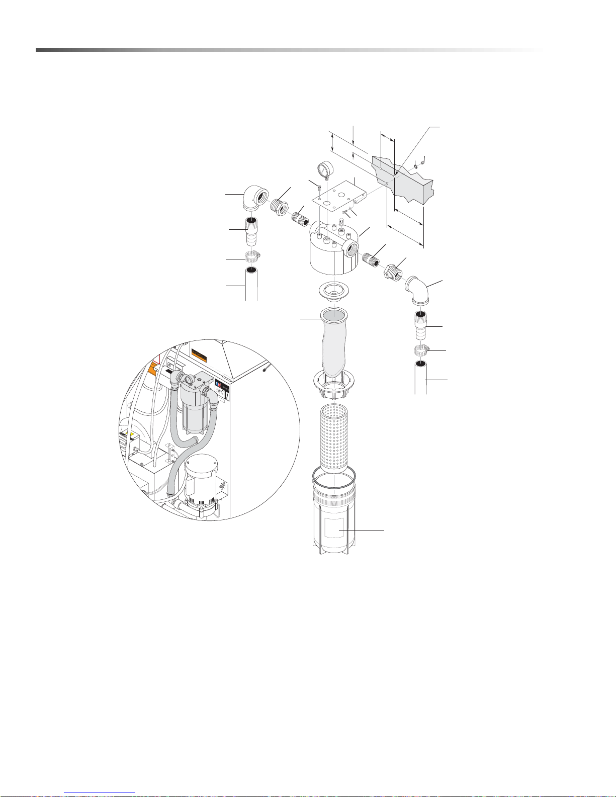
Filter Option 8.725-269.0
DANGER
HIGH VOLTAGE
WARNING
Assembled in US
A
Co
n
ta
in
s
co
m
pone
nts
from o
n
e or m
ore of
th
e
f
o
l
l
o
w
i
n
g
c
o
u
ntr
i
es
:
Uni
t
e
d
S
t
a
te
s
,
Austri
a,
Br
az
il
,
Ca
n
a
da
,
Chi
na
,
E
nglan
d
,
F
r
a
n
c
e
,
H
o
n
d
u
r
a
s
,
I
t
a
l
y
,
J
a
p
a
n
,
M
e
x
ic
o
,
R
om
an
i
a
,
T
a
i
wa
n
,
T
h
a
i
lan
d
,
V
i
e
t
n
a
m
.
I
NTEN
D
ED
F
OR
IND
O
O
R
US
E
HOUR METER
KEEP
DRY
15
14
10
13
12
1
3
4
5
6
2
9
11
8
7
2.625"
.625"
3.0"
0.313"
Dia
(3 Places)
5.75"
7.25"
16
8
6
5
4
3
50
Cuda 2412 Operator’s Manual 8.914-384.0 - V
Page 51
Filter Option 8.725-269.0
REF PART NO. QTY DESCRIPTION NOTES
1 8.724-071.0 1 FILTER HOUSING 4" X 10" W/PSI GAUGE
2 8.724-073.0 1 BAG, FILTER, 4" X 10", POLYESTER MESH, 200 MIC
3 8.724-081.0 2 NIPPLE, 1" X 2-1/2" SCH40 GALV
4 8.706-048.0 2 BUSHING, PIPE 1-1/4" X 1" NPT GALV
5 8.706-198.0 2 ELBOW, 1-1/4" FEMALE, 90 ° GALV
6 8.706-341.0 2 PIPE, BARBED MALE NPT 1-1/4" GALV
7 8.724-082.0 1 HOSE, 1-14" X 25" 200 PSI
8 8.709-081.0 4 CLAMP, SCREW #28
9 9.804-244.0 1 HOSE, 1-1/4" X 14-1/2" 200 PSI
10 8.930-052 .0 1 BRACKET, FILTER 2412
11 8.724-083.0 4 BOLT, TRI-ROUND, HEX ZINC, 5/16-18 X 3/4
12 9.802-70 0 .0 3 BOLT, 1/4" X 3/4", NC
13 9.802-802.0 3 WASHER, 1/4", FLAT
14 8.718-568.0 3 WASHER, 1/4", SEALING
15 9.802-773.0 3 NUT, 1/4" ESNA
16 8.904-658.0 1 DECAL, CAUTION FILTER PRESSURE
51Cuda 2412 Operator’s Manual 8.914-384.0 - V
Page 52

8.914-384.0 • Printed in U.S.A.
 Loading...