

Page 1
Cubix Corporation 2800 Lockheed Way Carson City, NV 89706-0719 Page 1
Sales 800.829.0550 http://www.cubix.com [email protected] xpander-rackmount2-g3 20181115
Xpander Rack Mount 2 Gen 3
HPC Version User Guide
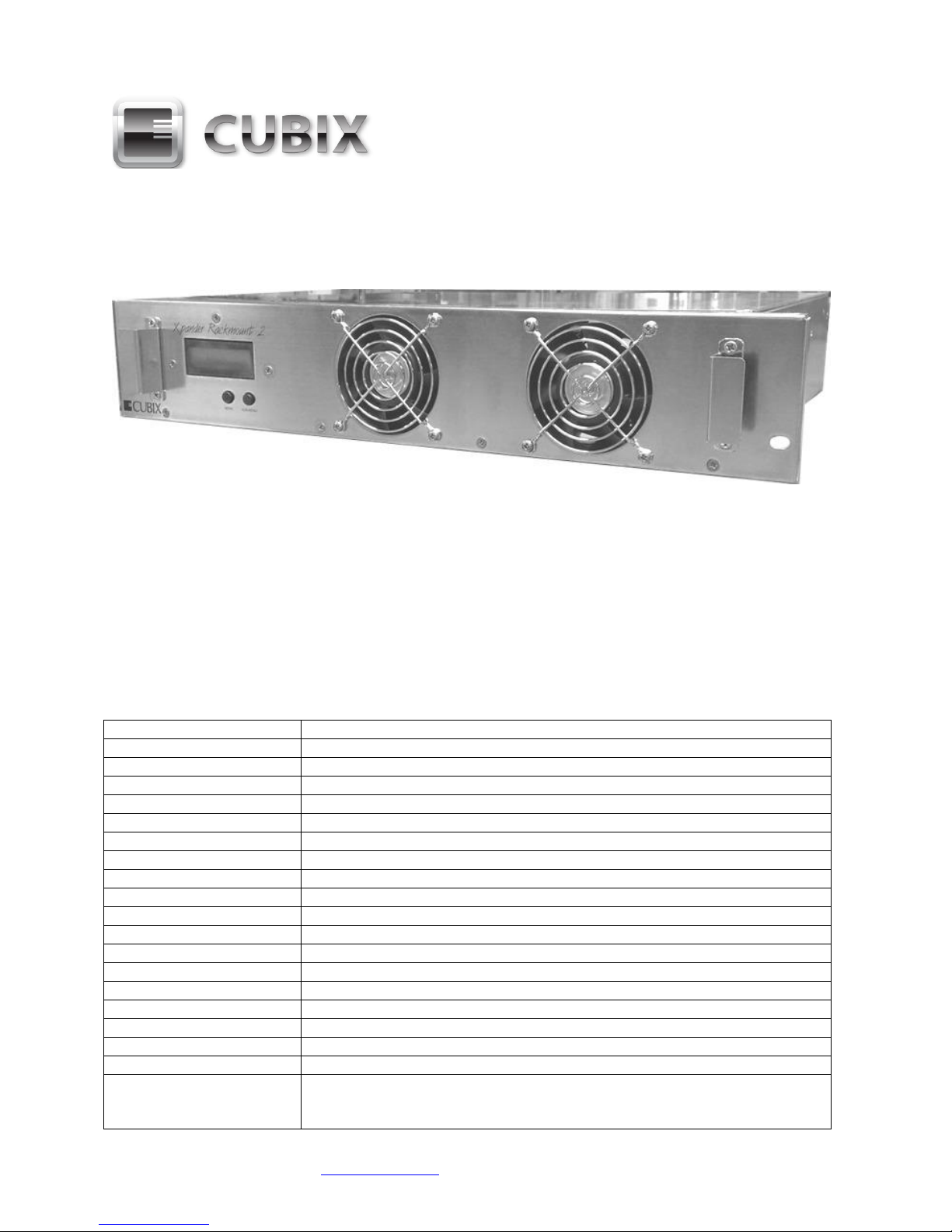
Xpander Rack Mount 2 is a 2U rack mount PCI Express (PCIe) expansion enclosure that
enables connection of two passively-cooled accelerators to a host computer. The host must
have a PCIe x16 expansion slot available for the host interface controller (HIC). Rack Mount 2
provides two PCIe x16 slots. Connect a HIC in one host computer to one Xpander.
With a HIC installed, a single host computer can support two double-wide, passively-cooled
accelerators. It connects to one HIC in the host computer. Rack Mount 2 provides two PCIe
Generation 3 (Gen 3) x16 slots for graphical processing units (GPUs) or other accelerators. For
example, use NVIDIA Compute Unified Device Architecture (CUDA) -enabled GPUs or Intel
Xeon Phi coprocessors for high-performance computing (HPC).
A HIC in a host computer’s PCIe Gen 3.0 x16 slot provides the full connection transfer rate with
Xpander. For example, the HIC in a PCIe Gen 3.0 x16 slot provides a theoretical transfer rate of
8.0Gbs x16 = 128Gbps.
Xpander Rack Mount 2 Gen 3 Technical Specifications
Expansion slots, x16 std
PCI Express Gen 3.0 x16 mechanical / electrical
Number of slots
2 slots in one mainboard
Form factor support
2 double-wide, full-length, full-height accelerators
Connecting cable
External PCI Express x16, 136-pin cable
Cable / connector
x16 / 136-pin
Length, standard
2.00meters (78.74inches or 6.56feet)
Length, optional
1.00meter (39.37inches or 3.28feet)
Connector duty cycle
250 mating cycles maximum per connector
PCIe x16 HIC
Host interface controller, install in a PCIe x16 slot
PCIe Gen 3.0 slot
Provides a theoretical 128Gbps data transfer rate
PCIe Gen 2.0 slot
Provides a theoretical 80Gbps data transfer rate
PCIe Gen 1.0 slot
Provides a theoretical 40Gbps data transfer rate
Front panel LCD
Main menu = left button; sub-menu = right button
Cubix Corporation
MIB assembly and revision; management firmware revision
Power supply status
Standard main power
Temperature status
3 sensor readouts in degrees Centigrade (C)
Fan status
Fan status, voltage percent (%) speed
PCIe link status
x16 cable connected; 8.0Gbps x16 link speed
x16 cable
Connected or not connected status
Slot 1 - 2 x16 transfer
rate, theoretical
PCIe Gen 3.0, 8.0Gbps x16 = 128.0Gbps
PCIe Gen 2.0, 5.0Gbps x16 = 80.0Gbps
PCIe Gen 1.0, 2.5Gpbs x16 = 40.0Gbps
Page 2

Cubix Corporation 2800 Lockheed Way Carson City, NV 89706-0719 Page 2
Sales 800.829.0550 http://www.cubix.com [email protected] xpander-rackmount2-g3 20181115
Rear panel
1 power input receptacle and 1 x PCIe x16 cable receptacle
Cooling fans
2 x fans run at 90cfm (cubic feet per minute) maximum
Air flow direction
Front to rear
Xpander power up
Fan is full on for 10s (seconds)
Fan speed, minimum
50% (6Volts) at 25 degrees C or less
Fan speed, maximum
100% (12Volts) at 50 degrees C or more
Fan speed, range
25 degrees C to 50 degrees C in gradual, linear progression
Normal operation
D1 LED = 1 pulse of 10ms (millisecond) on for every 700ms off
Error indication
D1 LED = 4 pulses of 10ms on for every 700ms off
Error conditions
[1] No fan tachometer or [2] no temperature sensor connected
AC power supply
Single-phase, auto-ranging, 100 - 240VAC, 9.5 - 4.5Amps, 50 / 60Hz; total
output power is not to exceed 800Watts
Operating environment
0° to 30° Celsius (32° to 86° Fahrenheit) temperature
5% to 80% non-condensing humidity
Dimensions (2U)
3.50" H x 19.00" W x 16.00" D (8.89cm H x 48.26cm W x 40.64cm D)
Weight
18.50lbs (8.39kg) with no GPUs
Warranty / period
Parts & labor return to manufacturer / 2 years
Ext. warranty period
Optional 3 years
Included
Rack Mount 2 includes two cooling fans, an 800W power supply and a power cord as well as
one 2-slot main board with risers, one PCIe x16 HIC and one external PCIe x16 cable. It does
not include installation media because installation requires no driver or other software. The only
drivers you install are those for the devices you install. Cubix provides a standard, two-year
warranty with the purchase of each Rack Mount 2.
Optional
The standard external PCIe cable length is 2meter. Optional 1m PCIe cable is also available.
The maximum duty cycle for PCIe cables is 250 mating cycles. Cubix offers a third-year
warranty option on Xpander products for a total of three years.
Quick Start Without Detail
Ignore this step if you wish. Install a GPU in the host system and install device drivers. Once
you have verified operation, shut down, move the GPU to Xpander, install the HIC in the same
slot within the host computer, connect Xpander to the HIC using the cable provided, connect
power to Xpander Rack Mount 2. Boot the host computer. If the host operating system (OS) is
plug-n-play, the OS detects the hardware devices and loads device drivers.
Start-up / Test / Installation Procedure With Detail
Check your host computer motherboard vendor’s Website for device driver and firmware
updates, especially those that may affect multiple accelerators. During this procedure, place the
Rack Mount 2 on a stable surface. Use a Philips #2 screwdriver for this procedure. Do not install
graphics or other controllers until instructed to do so within this procedure. Cubix recommends
that you do not install your first Rack Mount 2 enclosure in the rack mount cabinet until you have
finished.
1. Switch off AC power to the host computer. Leave the power cord connected.
2. Switch off AC power to Xpander Rack Mount 2.
3. Install the x16 HIC in a PCIe x16 slot within the host computer.
Page 3
Cubix Corporation 2800 Lockheed Way Carson City, NV 89706-0719 Page 3
Sales 800.829.0550 http://www.cubix.com [email protected] xpander-rackmount2-g3 20181115
4. Remove the screws holding in place the Xpander top cover, remove the top cover and set it
aside.
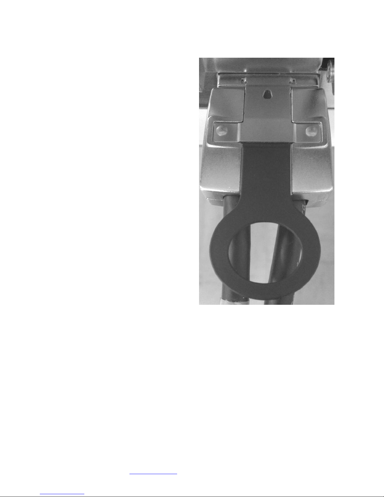
5. Connect the external PCIe cable from the
Xpander to the HIC in the host computer.
Make sure the cable connector seats firmly
in the HIC port. You will feel the cable
connector click into place. See the image of
a properly-seated connector at the right.
6. Connect a power cord to the receptacle at
the Xpander enclosure rear.
7. Power on the host computer. Xpander also
powers on. If you have properly seated the
HIC in the host PCIe slot, you will see the 8
LEDs at the top edge of the HIC light steady
green.
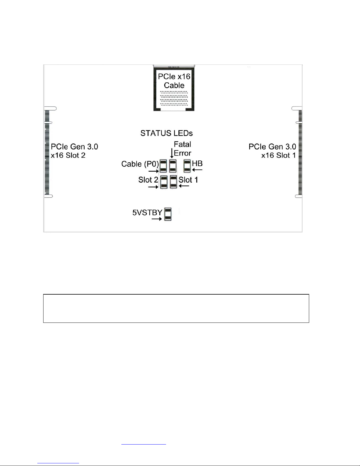
8. Check the mainboard Cable (P0) LED,
which should light steady green. This
indicates that the connection between the
HIC and Xpander mainboard is good. The
5VSTBY LED should also light steady
green. See the image at the top of the next
page.
Page 4
Cubix Corporation 2800 Lockheed Way Carson City, NV 89706-0719 Page 4
Sales 800.829.0550 http://www.cubix.com [email protected] xpander-rackmount2-g3 20181115
Confirm that interior Cable LED (P0) is lit green. The unit fans are spinning.
Xpander is functioning properly once the Cable LED
(P0) lights green. Proceed to install adapters.
9. Switch off AC power to the host computer. Leave the power cord and the external PCIe
cable to the host computer connected.
10. Switch off power and remove the power cord from Xpander.
Warning
Before installing or removing cards in Xpander, switch off AC power and wait for the
mainboard 5V Standby LED to power off.
Page 5
Cubix Corporation 2800 Lockheed Way Carson City, NV 89706-0719 Page 5
Sales 800.829.0550 http://www.cubix.com [email protected] xpander-rackmount2-g3 20181115
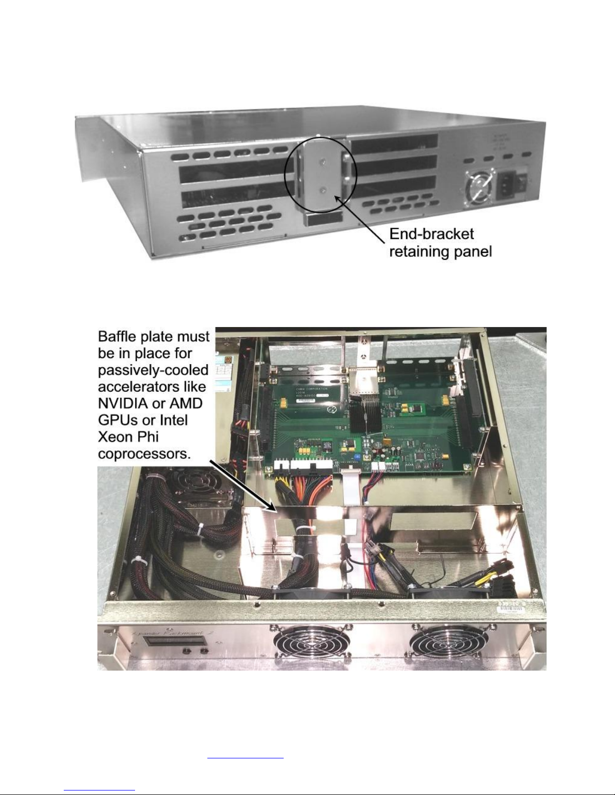
11. Remove the two screws holding the end-bracket retaining panel from Xpander rear and
remove the retaining panel. See the image below.
12. Install the accelerators in the appropriate riser slots. Make sure the baffle plate remains in
place. The baffle plate is required for passively-cooled accelerators like NVIDIA or AMD
GPUs or Intel Xeon Phi coprocessors.
Page 6
Cubix Corporation 2800 Lockheed Way Carson City, NV 89706-0719 Page 6
Sales 800.829.0550 http://www.cubix.com [email protected] xpander-rackmount2-g3 20181115
13. Install blank end-brackets, if required. Find 3 x blank end-brackets in Xpander packaging.
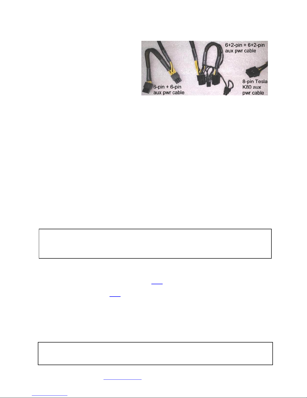
13. Connect PCIe auxiliary (aux) power
cables to the accelerators. Aux
power connectors are located at the
rear of each accelerator. Rack Mount
2 provides three sets of auxiliary
power connectors. See the image of
aux power connectors at the right.
14. Replace the two screws holding the
end-bracket retaining panel on
Xpander rear.
15. Install the hex-head screws that seat the end-brackets in place.
16. Connect GPU video port(s), if needed, to monitors. This step is especially important for
Linux, because X Windows crashes if you have not connected video ports to monitors. If you
cannot connect monitors to installed GPU video ports, you can edit the Device section of
/etc/X11/xorg.conf to define which GPU X Windows should use as the primary display
device. For example:
Section "Device"
Identifier "Device0"
Driver "nvidia"
VendorName "NVIDIA Corporation"
BoardName "Quadro M6000"
BusID "PCI:8:0:0"
EndSection
To determine the BusID for the GPU you wish to use as the primary display, run the scanpci
tool discussed in Step 19.
17. Install the single-wide cards at the far right facing the rear of Xpander.
18. Power up the host computer and Xpander to confirm that the appropriate Xpander slot link
LEDs are lit green, which confirms that you have installed the controller(s) correctly in each
slot.
19. Confirm that your operating system (OS) has detected the new controller(s). In a PC running
Microsoft® Windows®, check Windows Device Manager. Within Windows, you can also run
GPU-Z, a utility available for free download here. In a PC running Linux, run the following:
root# > XFree86 –scanpci
Read more about scanpci here.
20. If all the Cable Link and slot LEDs are green but your OS does not detect the GPUs, shut
down the OS gracefully, power down Xpander and reseat the GPUs in each PCIe slot. Make
sure you seat each GPU firmly in its slot and that you seat all aux power connectors firmly.
21. Power up the host computer and Xpander.
22. Install the appropriate graphics or other controller driver(s) using the vendor’s procedure.
23. Replace the Xpander front top cover and replace the screws.
Warning
Replace the cover as soon as possible to allow for proper cooling. Do not run Xpander
without the cover for more than a few minutes.
Note
Slot LEDs should light steady green. If they are flashing, it may be because the GPUs in the
slots do not have a processing load. Apply a processing load on the GPUs. If the slot LEDs
still flash green, check the vendor’s link for a driver update.
Page 7
Cubix Corporation 2800 Lockheed Way Carson City, NV 89706-0719 Page 7
Sales 800.829.0550 http://www.cubix.com [email protected] xpander-rackmount2-g3 20181115
Normal Power On/Off Procedure
1. With Xpander connected to the host computer and running, shut down the host normally.
2. With Xpander connected to the host computer and with power connected to both, switch on
Xpander first. Switch on the connected host computer; both will boot.
Install Xpander in a Cabinet
For this procedure, use a Philips #2 screwdriver,
a flat-blade screwdriver and a 3/8” wrench or
socket and drive. When lifting the Xpander into
place, ask for assistance. Mount it close enough
to the host computer so that the external PCIe
cable will reach. Mount Xpander either
immediately above or immediately below the
host computer(s) in the cabinet.
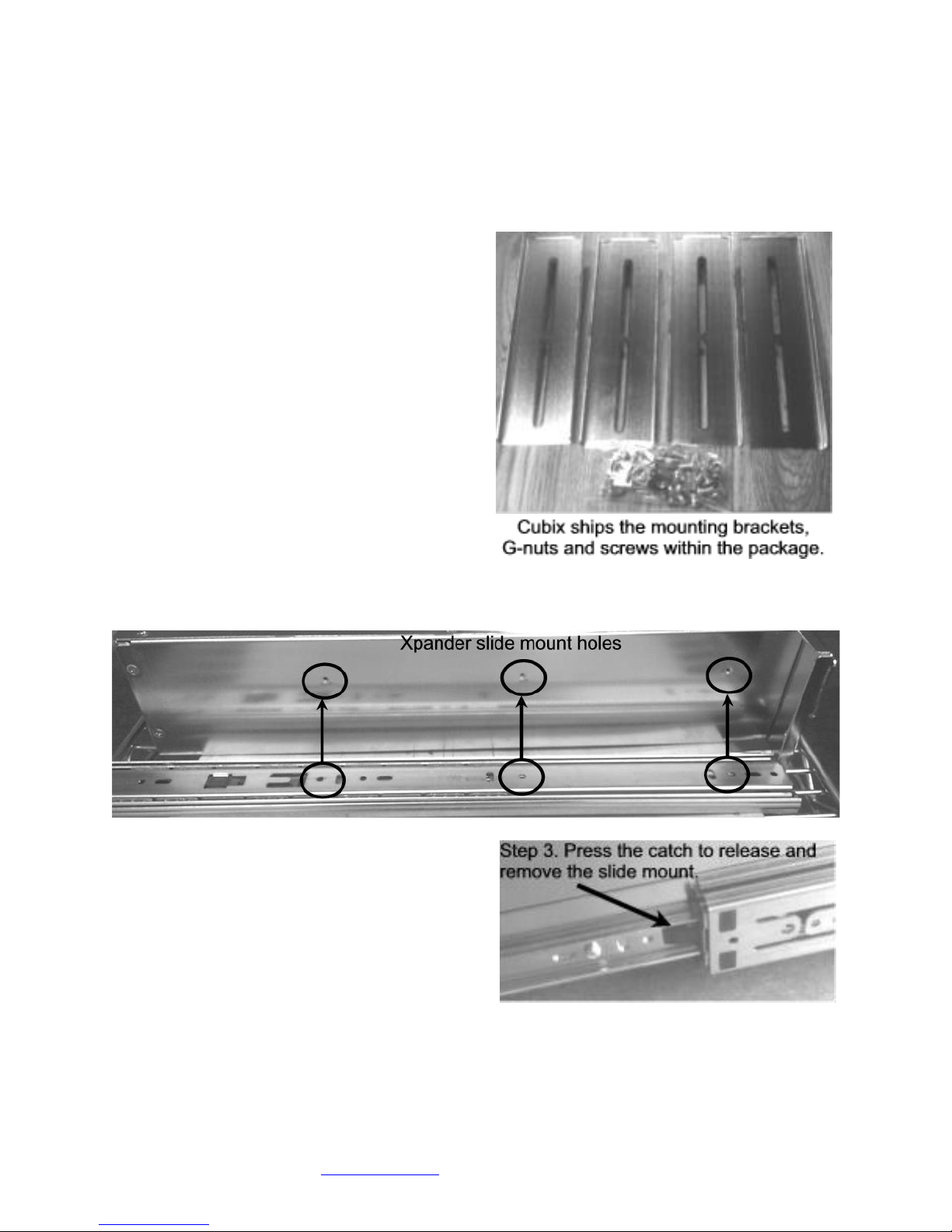
Within packaging, you will find four brackets that
mount within the four corners of your rack mount
cabinet, screws, nuts and G-nuts for use in
mounting Xpander within a cabinet. See the
image at the right.
1. Shut down the host and Xpander normally
and disconnect all data and power cables
connected to Xpander.
2. Find in packaging the rackmount slide rails with a bag of 8 x mounting screws taped to one
of the rails.
3. Remove the inner slide rail, or slide mount,
from the outer rail and mount it to Xpander
using the Xpander slide mounting holes. To
release each outer slide mount, slide it
toward the rear of the enclosure until it stops.
Press the catch to release and remove the
outer slide mount as you can see in the
image at the right.
4. Determine where to mount the Xpander slide
mounts in your cabinet.
5. Mount the front and rear mounting brackets (Part # S32760A) to each slider assembly with
the bolts and nuts provided in the packaging.
6. Repeat the process for the other front and two rear mounting brackets and slider assembly.
Page 8
Cubix Corporation 2800 Lockheed Way Carson City, NV 89706-0719 Page 8
Sales 800.829.0550 http://www.cubix.com [email protected] xpander-rackmount2-g3 20181115
7. Tightly secure the screws holding the sliders to the front and two rear mounting brackets on
each side of the cabinet.
8. Check the two rails on each side and check from front to rear to make sure that you have
mounted the rails so that they are level within the cabinet.
9. Lift the Xpander, line up the inside slider with the slider assembly mounted in your cabinet
and carefully slide it into place.
10. Try sliding the Xpander in and out slightly to make sure it moves freely.
11. Secure Xpander into place within the cabinet using the front-panel screws provided. Use the
Philips #2 screwdriver.
12. Connect the PCIe x16 external cable to the HIC in the host computer.
13. Connect power to Xpander.
Access Rack Mount 2 Interior
For this procedure, use a Philips #2 screwdriver. For accessing Xpander to add, move or
replace GPUs or other adapters, use the following procedure.
1. Shut down gracefully the host computer connected to Xpander.
2. Switch off power and disconnect the power cord.
3. Remove the two front-panel screws that secure Rack Mount 2 to the rackmount cabinet.
4. Gently pull the Xpander toward you.
5. Remove the screws holding in place the Xpander front top cover, remove the top cover and
set it aside.
6. Make sure the 5V Standby LED in Xpander is off.
7. Remove the screws holding each of the end-brackets.
8. Remove the two screws holding the end-bracket retaining panel from Xpander rear and
remove the retaining panel.
9. Remove and replace the accelerators in the appropriate riser slots. Make sure the baffle
plate remains in place. The baffle plate is required for passively-cooled accelerators like
NVIDIA or AMD GPUs or Intel Xeon Phi coprocessors.
14. Install blank end-brackets, if required. Find 3 x blank end-brackets in Xpander packaging.
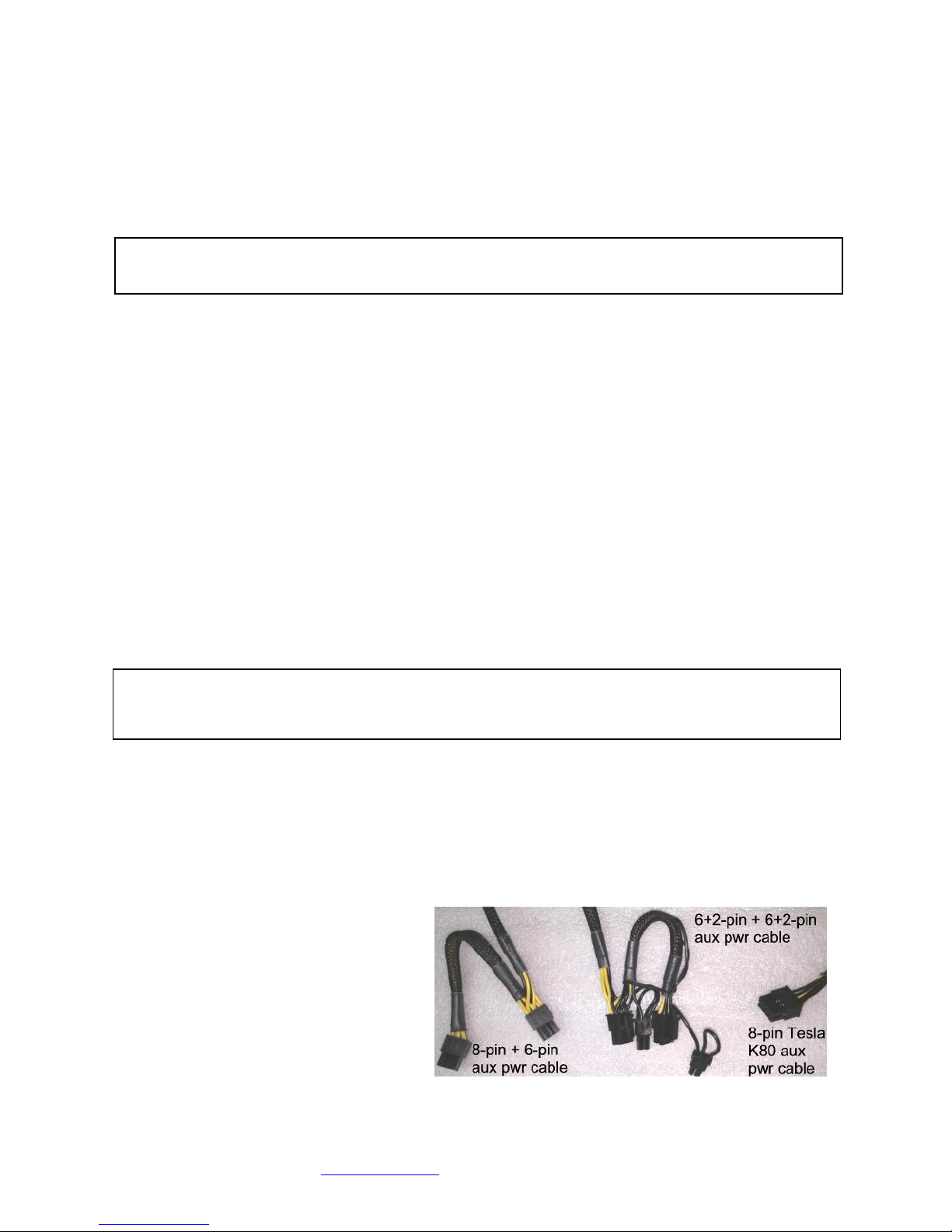
24. Connect PCIe auxiliary (aux) power
cables to the accelerators. Aux
power connectors are located at the
rear of each accelerator. Rack
Mount 2 provides three sets of
auxiliary power connectors. See the
image of aux power connectors at
the right.
25. Replace the two screws holding the
end-bracket retaining panel on
Xpander rear.
Warning
Before lifting Xpander into place, request assistance.
Warning
Before installing or removing cards from GPU-Xpander, switch off AC power and wait for the
5V Standby LED to power off.
Page 9
Cubix Corporation 2800 Lockheed Way Carson City, NV 89706-0719 Page 9
Sales 800.829.0550 http://www.cubix.com [email protected] xpander-rackmount2-g3 20181115
10. Replace the Xpander top cover and screws.
11. Gently slide Xpander back in place.
12. Secure Xpander into place within the cabinet using the front-panel screws provided. Use the
Philips #2 screwdriver.
13. Connect the PCIe x16 external cable to the HIC in the host computer.
14. Connect power to Xpander.
Front Panel LCD
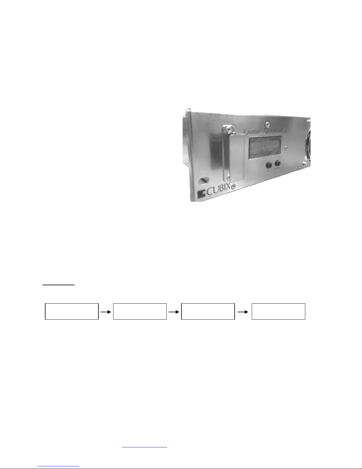
Xpander Rackmount 2 front panel LCD
provides enclosure details and status.
Beneath the LCD are two buttons: left button
scrolls through main-menu and right button
scrolls through sub-menu.
When you first connect power, Xpander
comes up in standby mode. The LCD displays
Cubix on the top line and Corporation on the
bottom line. This is the Start menu. Access all
other main menu items by pressing the left
button.
The upper right corner of the LCD shows a flashing asterisk *. This indicates that the on-board
Micro-Controller Unit (MCU) is running properly. If the asterisk is not flashing or the LCD is not
responding, reset the MCU by pressing and holding the left button for 3 seconds. A
corresponding HB (heartbeat) LED on the main board also shows the MCU is working.
When a fault occurs, the LCD will jump to that fault and the LCD backlight will flash on / off.
Press the left button to acknowledge the fault and the LCD will stop flashing and enable normal
operation. The LCD will continue to display the fault at the applicable sub-menu until you clear
the fault.
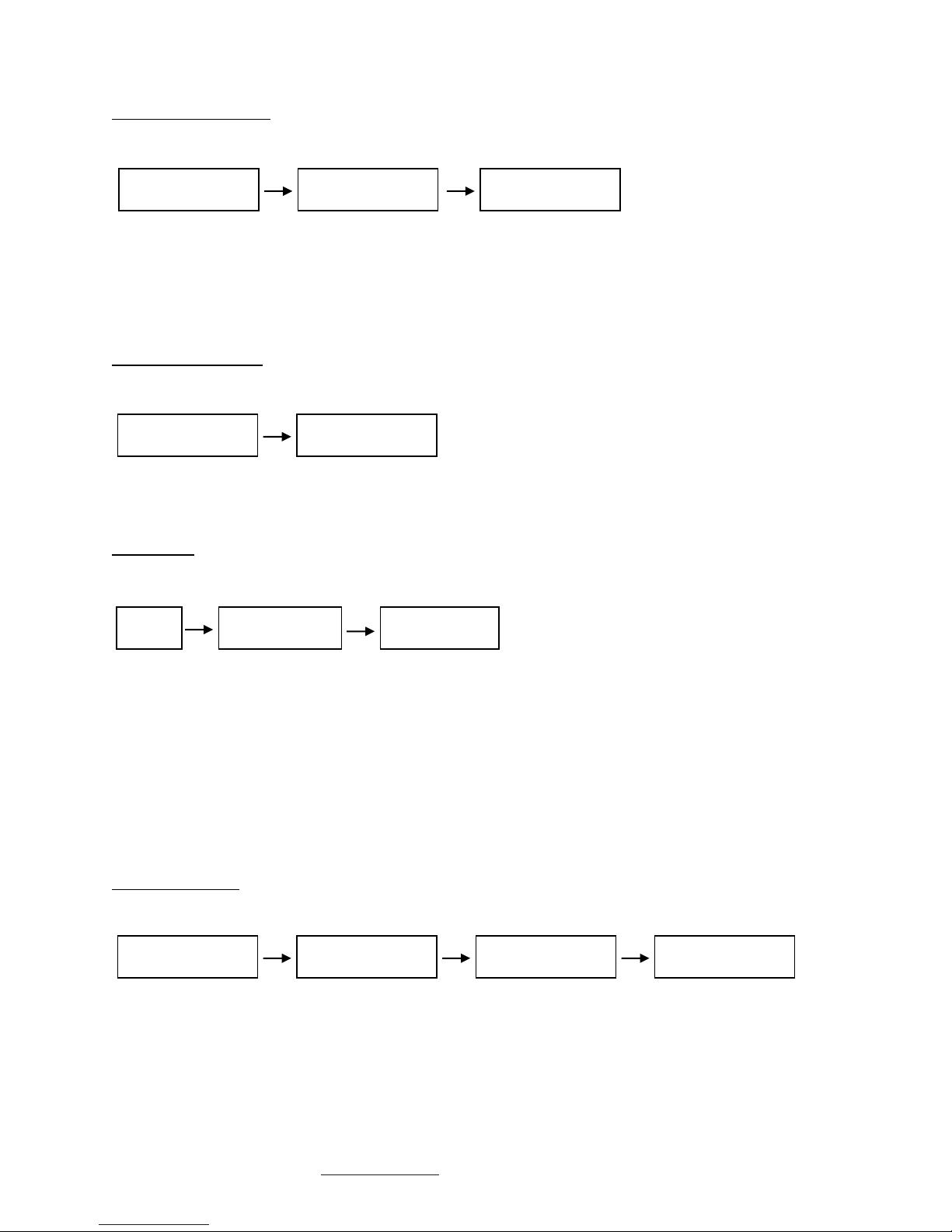
Start Menu
Menu Sub-menu Sub-menu Sub-menu
Main menu: Cubix Corporation
Sub-menu: PCB Assembly
• Board Number
• EEPROM Revision
• Board Revision
Sub-menu: MCU (Micro-Controller Unit) Firmware
• Release Number
• Release Date
Sub-menu: Cubix Serial Number
Cubix
Corporation
Cubix
A09150 Rev 0B 0A
MCU Firmware
Rel 01 04-28-14
Serial Number
10200001
Page 10
Cubix Corporation 2800 Lockheed Way Carson City, NV 89706-0719 Page 10
Sales 800.829.0550 http://www.cubix.com [email protected] xpander-rackmount2-g3 20181115
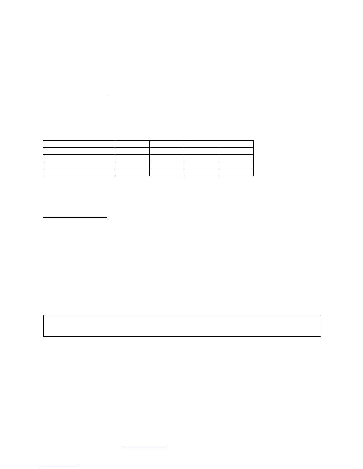
Power Supply Status
Menu Sub-menu Sub-menu
Menu: Power Supply Status
Sub-Menu: Power Supply Status:
• PWR Standby = Main power is off; system is in standby
• PWR ON-Good = Main power is on; +3.3V, +5V, +12, -12V are within spec.
• PWR ON-FAULT = Main power is on; +3.3V, +5V, +12V, or -12V is out of spec.
Temperature Status
Menu Sub-menu
Menu: Temperature Status
Sub-Menu: Display the temperature of the 3 temperature sensors in degrees Celsius.
Note: If a temperature sensor fails, FLT (fault) appears under the failed sensor.
Fan Status
Menu Sub-menu Sub-menu
Menu: Fan Status
Sub-Menu: Indicates fan status for fans 1-2
Note: Fan speed is controlled by adjusting fan voltage based on sensed system temperature. Fan voltage
adjusts from 6V min (25deg C or lower) at 50% to 12V max (50deg C or higher) at 100%. Fan voltage is
the same for all fans.
Status: PWR OFF is 0V at 00%; system is in standby.
Status: Running aaV at pp%; fan is good; aa = fan voltage and pp = fan power percent (%).
Status: STOPPED is 12V at 100%; fan fault: fan voltage is set to full on.
Status: NO FAN aaV at pp%; Xpander can be configured with 1, 2 , 3, or 4 fans. No fan means
fan is not installed.
PCIe Link Status
Menu Sub-menu Sub-menu Sub-menu
Menu: PCIe Link Status
Sub-Menu: Indicates x16 PCIe cable installation status
• Connected x16 cable is properly connected to the HIC
• NOT-Connected x16 cable is not properly connected to the HIC
Sub-Menu: x16 PCIe cable link speed and link width. Speed and width depend on the host capability.
• Speed: 8.0Gb/s
Power Supply
PWR ON-Good
Power Supply
Status
Temperature
Status
Tmp1 Tmp2 Tmp3
24C 25C 26C
Fan
Status
Fan 1
Running 7V 70%
Fan 2
Running 7V 70%
PCIe Link
Status
PCIe X16 Cable
Connected
PCIe Cable
8.0Gb/s X16
PCIe Slot n
8.0Gb/s X8
Power Supply
RPS ON-Good
Page 11
Cubix Corporation 2800 Lockheed Way Carson City, NV 89706-0719 Page 11
Sales 800.829.0550 http://www.cubix.com [email protected] xpander-rackmount2-g3 20181115
• Width: x1, x2, x4, x8, x16 and “NO Link” when the host did not successfully link or Xpander is
in standby power.
Sub-Menu: Link speed and link width for slots 1-4.
• Speed: 8.0Gb/s
• Slot 1 - 4 width: x1, x2, x4, x8, and “NO Link” when the slot is empty, unsuccessful link, or
Xpander is in standby power.
LCD Backlight Control
Press right button to toggle the LCD backlight On / Off.
Fan Speed Control
Shunts JP7 and JP8 are used to change the fan profile to reduce fan noise.
Fan Profile
JP8
JP7
*Tmax
*Tmin
Performance Mode
1-2
55C
20C
Quiet Mode
1-2 65C
30C
High Performance Mode
2-3
40C
5C
**GPU Mode
2-3
2-3
80C/40C
45C/5C
* Tmax - Fan Voltage ~12V, Tmin - Fan Voltage ~6V
**GPU Mode: Tmax: GPU temp = 80C, if no GPU is found Tmax = 40C (on-board temp sensors)
Tmin: GPU temp = 45C, if no GPU is found Tmin = 5C (on-board temp sensors)
GPUs supported: Quadro K6000, M6000 and P6000
Fan Profile Guidelines. GPU Mode supports 4 x double-wide GPUs like NVIDIA Quadro or GTX
Series. High-Performance Mode supports 2 – 3 double-wide GPUs. and Performance Mode
Performance Mode supports 2 x double-wide GPUs. Quiet Mode supports 1 x double-wide GPU
or 4 x single-wide GPUs.
Shipping Procedure
Before shipping Xpander, remove any installed graphics or other controller(s) using the
following procedure:
1. Switch off the host computer and disconnect power.
2. Disconnect Xpander from the HIC.
3. Gently pull Xpander toward you.
4. Lift Xpander down from the cabinet and set it on a stable surface.
5. Remove the screws holding in place the Xpander front top cover, remove the top cover and
set it aside.
6. Remove the screws holding each of the end-brackets.
7. Remove the two screws holding the end-bracket retaining panel from Xpander rear and
remove the retaining panel.
8. Remove the GPUs and other PCIe cards and blank end-brackets.
9. Replace the two screws securing the end-bracket retaining panel to Xpander rear.
10. Replace the screws for holding each of the end-brackets.
Warning
Before lifting Xpander out of a cabinet, ask for assistance.
Page 12

Cubix Corporation 2800 Lockheed Way Carson City, NV 89706-0719 Page 12
Sales 800.829.0550 http://www.cubix.com [email protected] xpander-rackmount2-g3 20181115
11. Pack the graphics cards or other controllers within the boxes in which you received them.
12. Replace the Xpander front top cover, replace the screws and remove the power cords.
13. Remove the HIC(s) from the host computer.
14. Within the original packaging, pack the Xpander, the power cords, the HIC(s) and the boxed
graphics cards. Include a copy of these instructions.
Troubleshooting Procedure
Issue: The front-panel LCD asterisk does not flash.
Resolution: Reset the LCD’s MCU by pressing and holding the left button for 3 seconds while
Xpander is running.
Issue: The HB LED inside Xpander flashes green.
Resolution: This is normal; it indicates that the on-board MCU is running properly.
Issue: Cable LED inside Xpander does not light green.
Resolution: Check the following:
• Confirm that the HIC is firmly seated in a PCIe slot within the host computer.
• Confirm that the cable connector is firmly seated HIC connector port.
Issue: Cable LED inside Xpander flashes green even though I have a PCIe x16 HIC
and cable.
Resolution: The internal Cable LED should light steady green. If the Cable LED flashes, it is
transferring data at a reduced bandwidth because you installed the PCIe x16 HIC
in a Gen 1 slot or a PCIe x8 (electrical) slot. If your HIC is PCIe x8, you installed
it in a Gen 1 slot. The HIC operates at full bandwidth when installed in a PCIe
Gen 2 slot.
Issue: Slot LED inside Xpander does not light green.
Resolution: Shut down the OS gracefully, power down Xpander and reseat the GPUs in each
PCIe slot. Make sure that you seat each GPU firmly in its slot and that you
connect all aux power connectors firmly.
Issue: Slot LED inside Xpander flashes green even though I installed a PCIe x16 Gen 3
GPU or card.
Resolution: Slot LEDs should light steady green. If they are flashing, it may be because the
GPUs in the slots do not have a processing load. Apply a processing load on the
GPUs. If the slot LEDs still flash green, check the vendor’s link for a driver
update.
Issue: All Cable and Slot LEDs are lit green, but your OS does not detect the GPUs.
Resolution: Shut down the OS gracefully, power down Xpander and reseat the GPUs in each
PCIe slot. Make sure that you seat each GPU firmly in its slot and that you
connect all aux power connectors firmly.
Issue: The front-panel LCD screen backlight is flashing on/off, which indicates a fault.
Resolution: Acknowledge the fault by pressing the Menu button, which will stop the LCD
flashing and the LCD will remain at the fault.
Warning
Remove GPUs or other adapters before shipping Xpander.
Page 13

Cubix Corporation 2800 Lockheed Way Carson City, NV 89706-0719 Page 13
Sales 800.829.0550 http://www.cubix.com [email protected] xpander-rackmount2-g3 20181115
Issue: After acknowledging a fault, the front-panel LCD screen backlight continues
flashing on/off, which indicates two or more faults. If multiple faults have
occurred, when you acknowledge the first fault, the LCD will jump to the next
fault and the LCD backlight will once again flash on/off. This continues until you
clear all faults.
Resolution: Acknowledge the fault by pressing the Menu button, which will either stop the
LCD flashing and the LCD will remain at the fault, or the LCD will jump to the
next fault and the LCD backlight will once again flash on/off.
Issue: The front-panel LCD screen either does not respond or is blank even though
Xpander is operating.
Resolution: Press and hold the MIB Select button to reset the Micro-Controller Unit (MCU).
Issue: The front-panel LCD screen either does not respond or is blank for a particular
MIB even though Xpander and the MIB are both operating.
Resolution: Press and hold the Menu (left) button for 3 seconds to reset the Micro-Controller
Unit (MCU). If the Xpander is running, the Xpander fans will turn on full speed for
10 seconds and then slow down to the operating speed set by the MIB local
temperatures.
 Loading...