

Page 1
www.3dcubicon.com
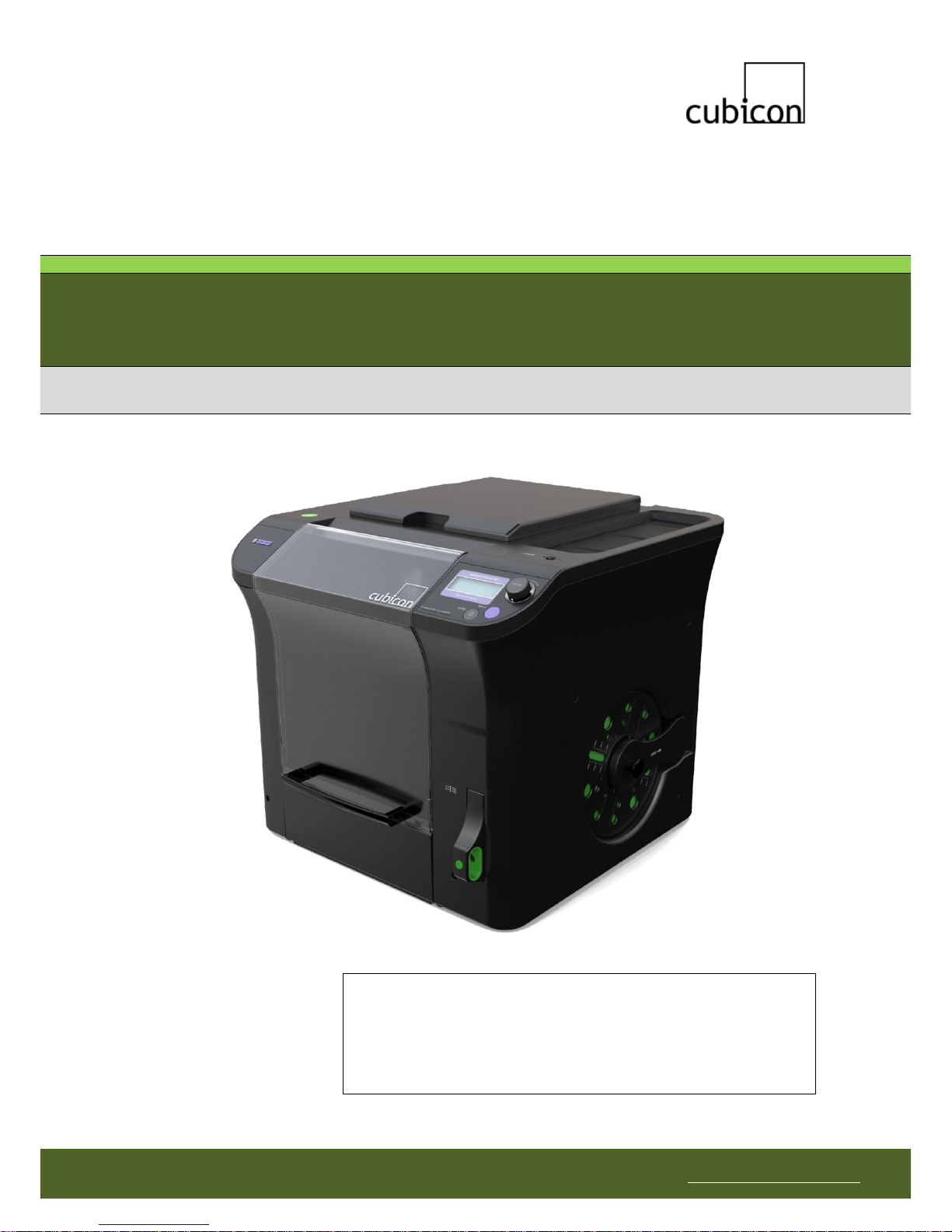
Cubicon Single (3DP-110F)
Quick Start Guide
∙ Please read the safety cautions carefully before using the product, and
use the product appropriately.
∙ This document is provided to ensure the safety of users and to
prevent property damage.
∙ The Quick Start Guide only provides information on how to unpack the
package and install it. Please refer to the Operation Manual for more
detailed information.
Page 2
Copyright Reserved HyVISION System Inc.
This document is the Quick Start Guide (141020,kr), and is subject to change without notice when necessary for
product improvements. HyVISION System does not take the responsibility for loss caused by any error in the
document or provisions and use of this document.
2
Thank you for purchasing Cubicon Single!
Please read this ‘Safety Caution’ before using the printer and always follow the guideline provided.
This guideline is provided to ensure the safety of users, prevent the injury of third parties and prevent
damage to the printer.
Failure to follow this guideline may lead to serious injuries or printer damage.
Since the printer generates a high level of heat during operation, there is the risk of burning if you place
your finger or another part of your body or fixtures inside the printer during operation. Place the body part
or fixtures only after the operation is terminated and the printer has been sufficiently cooled.
The printer has a number of moving parts, including the motor, belt and gear. There is the risk of injury or
property damage from being trapped if a body part or fixtures are placed inside the printer during an
operation.
Penetration of water or other liquids as well as the metal pieces or other conductive foreign substances
inside the printer can cause fire or electric shock. Please take care to avoid operating the printer with wet
hands, as this can cause fire or electric shock.
Select the installation site carefully to avoid causing injury to children or pets. Children or pets must be
observed and protected carefully if they are near the printer.
The printer and its parts have sharp edges. Be careful to avoid injury or printer damage.
Since the filament used in the printer can cause fire or injury, do not heat it or deform it with another piece
of equipment. Carefully handle the outputs and filament scraps, as swallowing them can cause suffocation,
etc.
Never use a volatile substance with the printer, as it can cause a fire or explosion. In addition, remove
ignition materials or flammable materials around the printer as they can cause fire.
The printer uses a high brightness LED for illumination. Do not look at it directly in order to protect your
eyes.
Do not destroy or alter the printer’s power cable or USB cable, and make sure that only the rated voltage is
supplied.
To move the printer, stop the printer operation and disconnect the power cable and USB cable after the
internal parts are sufficiently cooled and the printer is turned off.
Do not place a filament or object in an empty space inside the printer, as it can cause printer damage and
fire.
As the printer uses a melted material that may generate an odor, install the printer in a well-ventilated area.
Do not install the printer outdoors or in a vibrating, humid or dusty area.
Do not install the printer in an unstable or uneven surface.
In addition, please take care to remove any object that may be damaged by the heat or vibration generated
by the printer’s operation.
If an unauthorized filament or part is used with the printer, it may damage the product and/or violate the
conditions of the product warranty. Any problem caused as a result will not be covered by the warranty.
Do not disassemble or alter the printer except as specified in the Operation Manual, as it may cause the
injury or printer damage. Any problem caused as a result will not be covered by the warranty.
Do not apply excessive force or impact to the printer, as it may cause injury or printer damage. Read the
caution in the Operation Manual carefully before using the printer.
Safety Caution
Page 3
Copyright Reserved HyVISION System Inc.
This document is the Quick Start Guide (141020,kr), and is subject to change without notice when necessary for
product improvements. HyVISION System does not take the responsibility for loss caused by any error in the
document or provisions and use of this document.
3
The printer is packaged after a total test of output conditions.
This testing may leave traces of usage on the heating bed, nozzle, etc. Be assured that these are
traces of testing, and that there is no problem with the product.
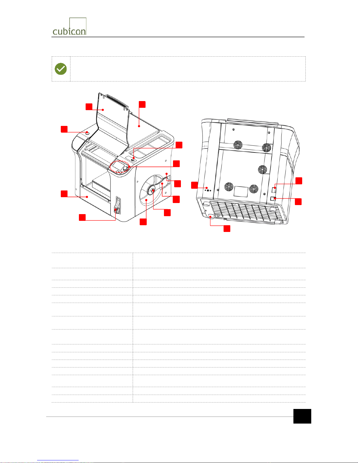
[1] Top door
Used for maintenance such as the filament replacement
(loading / unloading), separation of detachable extruder, etc.
[2] Front door
Used to pull out the molded part
[3] Inclinometer
Used to check levelness when the printer is installed
[4] Bottom door
Used for cleaning the bottom, etc.
[5] Clean filter case
Used to mount the clean filter
[6] SD memory insertion hole
Used to insert the SD memory
[7] LCD and operating buttons
Used to operate the LCD screen and printer
[8] Filament insertion hole
Used to supply the filament
(located at the inner top when the spool door is opened)
[9] Spool door
The door is used to fix the filament spool
[10] Spool door handle
Used to lock the spool door (should be locked after the spool is mounted)
[11] Spool carrier
Area in which the filament spool is mounted
[12] USB input (Type-B)
USB input terminal to connect to a PC
[13] Power switch
Main power switch for the printer
[14] Power input
Terminal to connect the power source of the printer
[15] Leveling foot
Used to set the horizontal levelness of the printer (4 at the bottom)
2
3
4
5
6
7
10
11
8
9
1
12
13
14
15
External Printer Parts
Page 4
Copyright Reserved HyVISION System Inc.
This document is the Quick Start Guide (141020,kr), and is subject to change without notice when necessary for
product improvements. HyVISION System does not take the responsibility for loss caused by any error in the
document or provisions and use of this document.
4
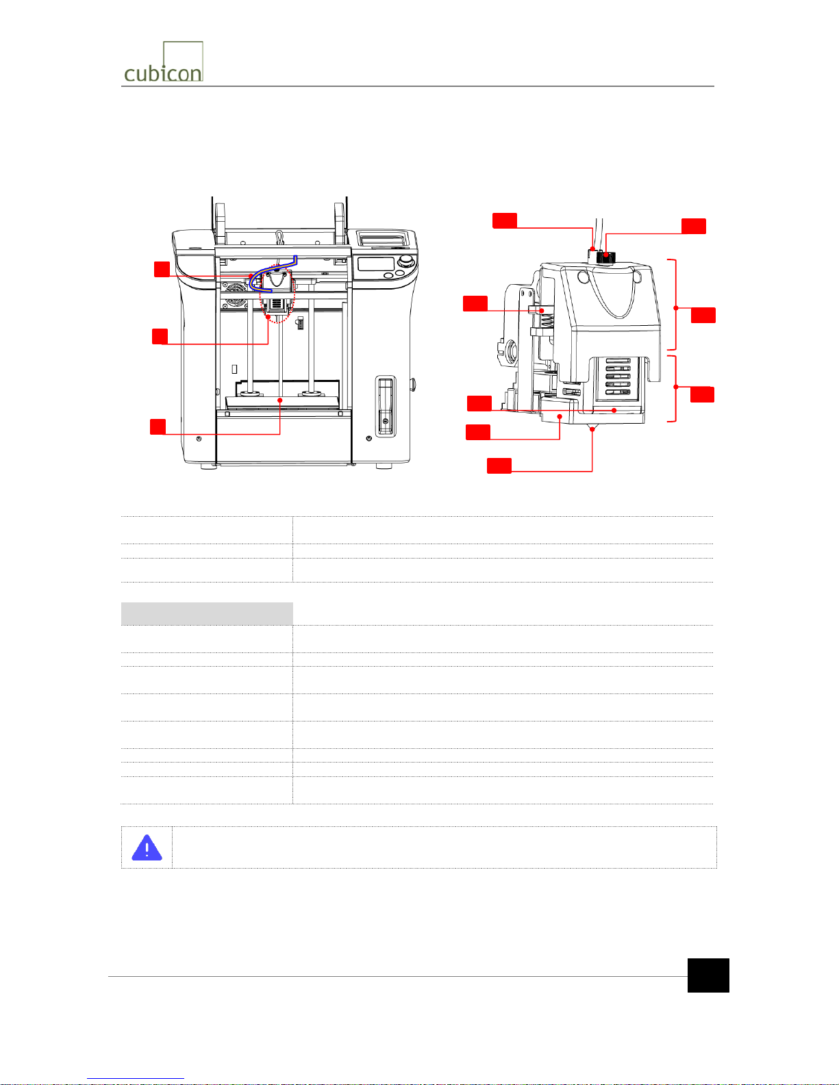
[1] Teflon tube
The path to supply the filament to the printer extruder (be careful not to bend,
etc.)
[2] Extruder part
The extruder exudes the filament and melts it through the nozzle
[3] Heating bed
The platform to output the printed material during printing
Extruder part
[E1] Filament insertion hole
Hole through which filament is inserted into the extruder; a Teflon tube is
placed inside it
[E2] Filament handle
Handle to manually pull the filament out of the extruder or insert it
[E3] Mold Lighting LED
White LED to check the molding status; located in the detachable extruder
part
[E4] Ventilation guide
A fixture sending the air from the molding fan to the molded parts; located in
the detachable extruder part
[E5] Nozzle
Nozzle through which the melted filament flows; located in the detachable
extruder part
[E6] Detachable screw
Fastening screws used to mount and dismount the detachable extruder part
[E7] Fixed extruder part
Fixed part of the extruder
[E8] Detachable extruder
part
Detachable part of the extruder
Do not touch the nozzle and heating bed of the detachable extruder during the printing
operation, as these are hot.
1
2
3
Internal Printer Parts and Extruder
E4
E2
E6
E7
E8
E3
E1
E5
Page 5
Copyright Reserved HyVISION System Inc.
This document is the Quick Start Guide (141020,kr), and is subject to change without notice when necessary for
product improvements. HyVISION System does not take the responsibility for loss caused by any error in the
document or provisions and use of this document.
5
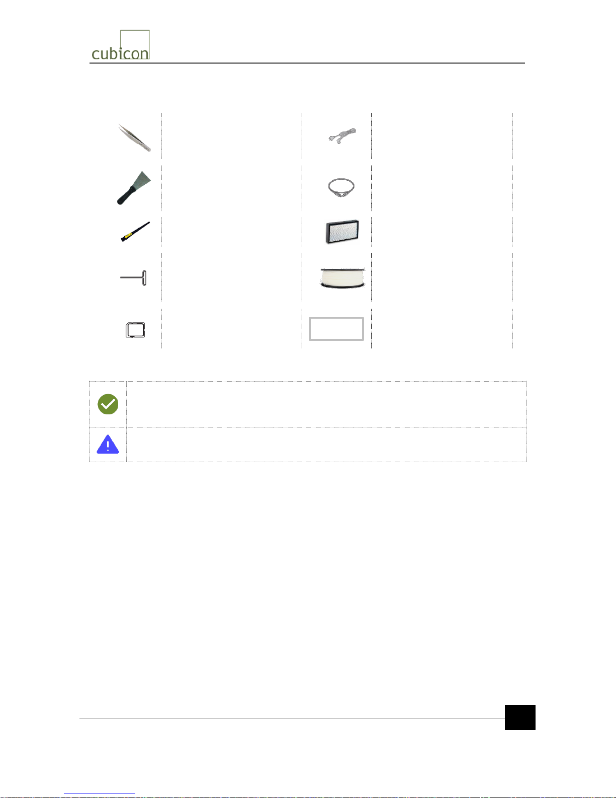
Tweezers (x1)
Used to remove foreign
substances, such as filament
residues
Power cable (x1)
The power cable for the printer
Scrapper (x1)
Used to separate the molded part
or remove foreign substances
from the heating bed
USB cable Type-A/Type-B (x1)
Connected to a PC and used for
output printing
Antistatic brush (x1)
Used to remove the pollutants
such as the filament residues.
Clean filter (x1)
Mounted in the clean filter case of
the main body
Nozzle pin ф=1.5mm (x1)
Used to clean inside of the nozzle
when the output quality has
deteriorated due to a polluted
nozzle.
Filament spool (x2)
Mounted in the spool carrier. A
filament spool is provided to both
PLA and ABS (random color).
SD Memory (x1)
Stores the slice files of 3D models
for molding used by the printer
Quick Start Guide /
Operation Manual
Included as a printout or a file in
the SD memory
* The filament spool and clean filter are not mounted in the printer, but are packaged separately.
* The type and specification of the accessories included in the part may be changed without
notice to enhance the product.
* Please use the Cubicon homepage or contact a distributor to purchase additional accessories.
Using an unauthorized filament or part may cause damage to the product. Any problem related
to the use of an unauthorized part will not be covered by the after-sales service. Always use
accessories supplied by Cubicon.
Accessories Included with Package
Operation
Manual
Page 6
Copyright Reserved HyVISION System Inc.
This document is the Quick Start Guide (141020,kr), and is subject to change without notice when necessary for
product improvements. HyVISION System does not take the responsibility for loss caused by any error in the
document or provisions and use of this document.
6
* Be careful when unpacking and installing the product, as excessive force or ripping can
damage the content.
* Considering the size and weight of the product, it is recommended to have two or more
people move the product.
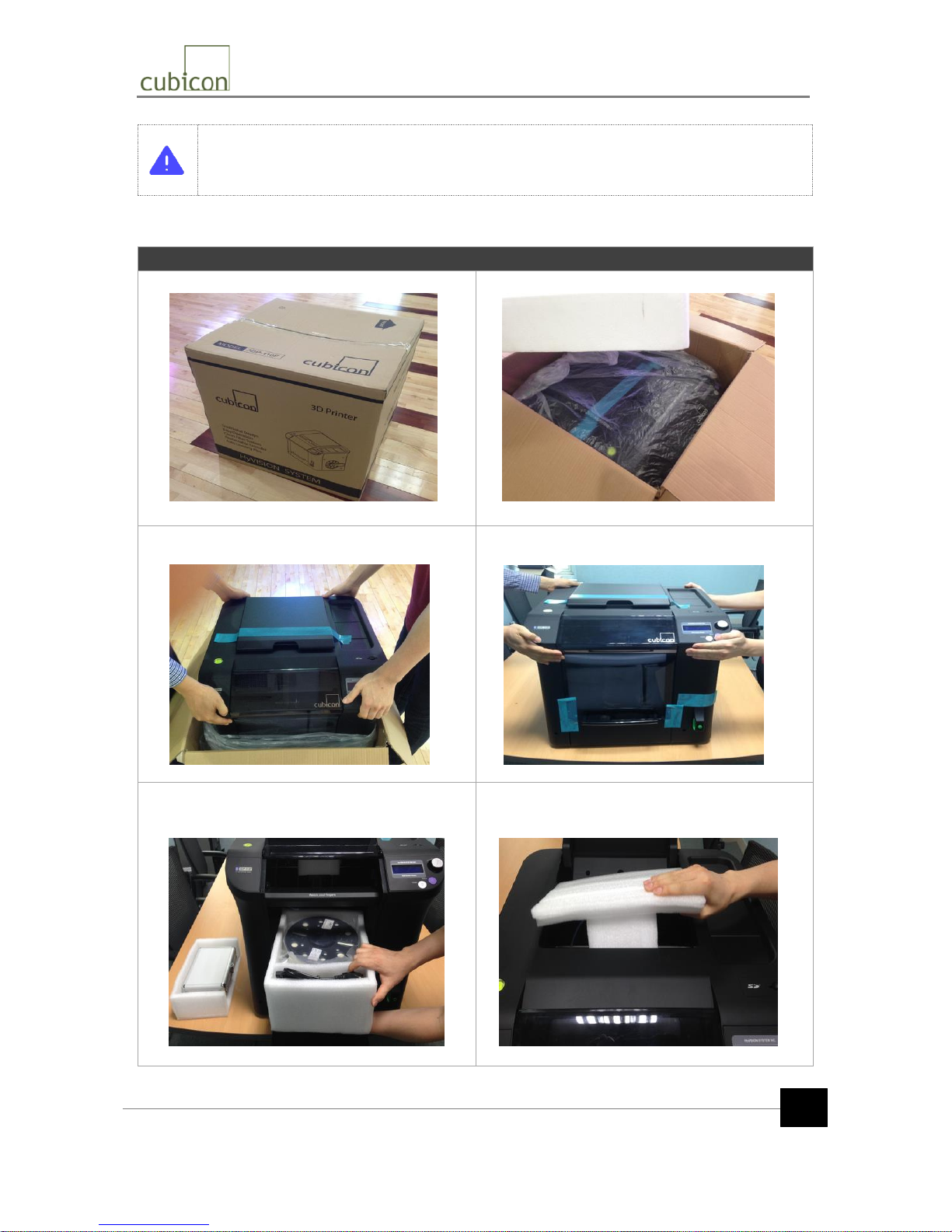
Unpacking
① Place the package on a level floor.
② Open the box and remove the top cover.
③ Pull the product out of the vinyl bag
(two persons recommended).
④ Move the product to its installation location
(two persons recommended).
⑤ Open the front door and pull out all internal parts
and accessories to make sure that they are all there.
⑥ Open the top door and pull out the extruder
package. Be careful not to bend the extruder-driven
cable or the Teflon tube.
Teflon Tube
Unpacking and Installation (1/4)
Page 7
Copyright Reserved HyVISION System Inc.
This document is the Quick Start Guide (141020,kr), and is subject to change without notice when necessary for
product improvements. HyVISION System does not take the responsibility for loss caused by any error in the
document or provisions and use of this document.
7
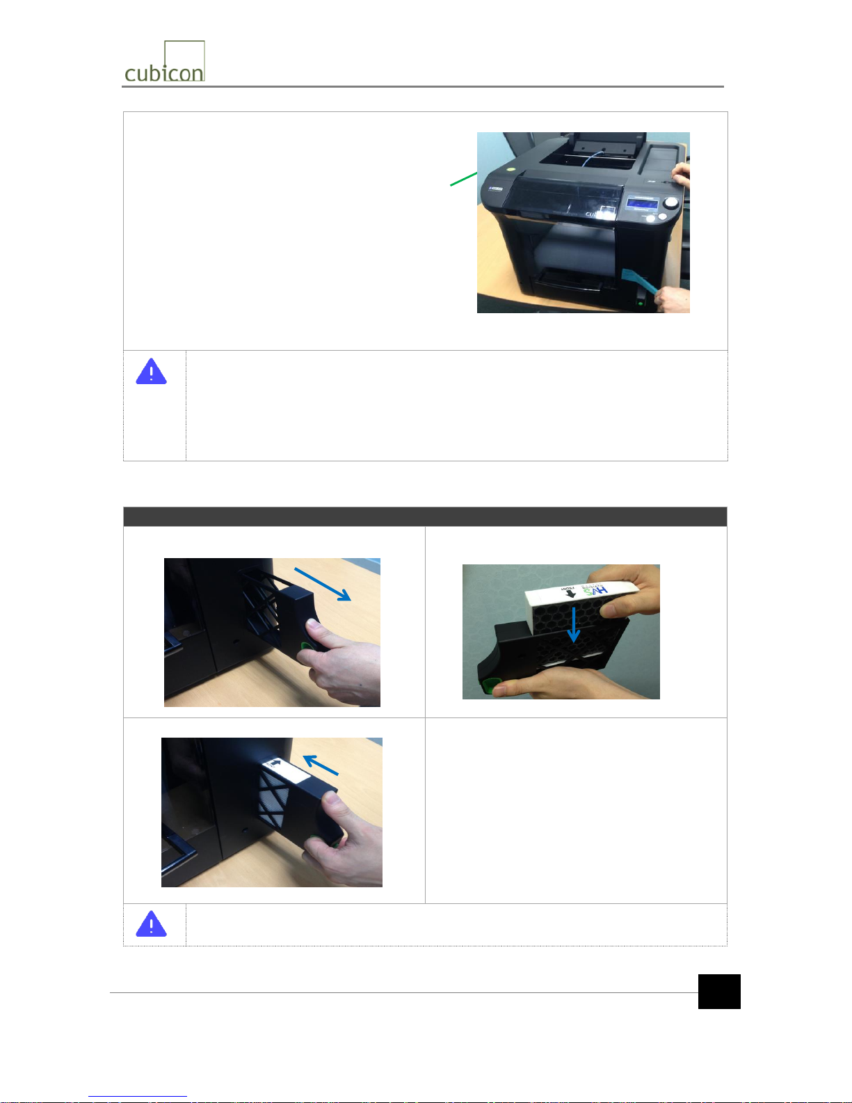
⑦ Remove the package and tape. Set the horizontal levelness of the printer by adjusting the feet, while referring
to the inclinometer.
* The driving part is fixed with packaging material only, without using a cable tie, in order to
prevent potential problems when the printer is operated. Please be careful not to damage
the part when removing the internal packaging material.
* The extruder-driven cable and the Teflon tube are located near the extruder fixing
packaging material. Since the extruder-connected cable and Teflon tube are the moving
path of the filament, they should be handled carefully to avoid damage from being
excessively pulled, bent or pressed.
Mounting of Clean Filter
① Pull out the clean filter case from the printer body.
② Place the clean filter inside the case.
Position the clean filter carefully.
③ Insert the clean filter case into the printer body.
Mount the clean filter in the correct position inside the case. If it is positioned incorrectly, the
filter performance will degrade and cause a malfunction of the ventilation fan.
Inclinometer
Unpacking and Installation (2/4)
Page 8
Copyright Reserved HyVISION System Inc.
This document is the Quick Start Guide (141020,kr), and is subject to change without notice when necessary for
product improvements. HyVISION System does not take the responsibility for loss caused by any error in the
document or provisions and use of this document.
8
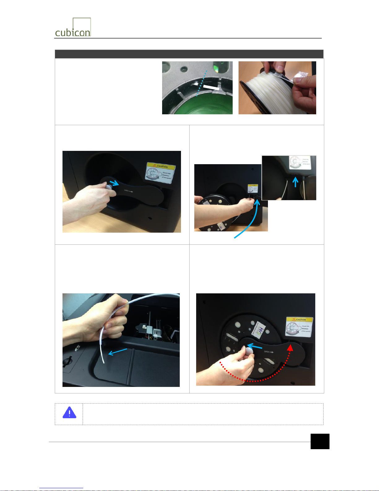
Mounting of Filament Spool
① Prepare the filament spool to be used.
Cut off the filament sticking out of the
filament fixing hole at the center of the
spool and remove the fixing tape of the
filament.
② Push the spool door handle on the printer body in
the direction of the arrow shown in the picture to open
the door of the spool carrier.
③ Slowly unwind the filament from the filament spool
and insert the filament into the filament insertion hole.
* Be careful of the spool rotation/insertion
direction.
④ Open the top door and push the filament all the way
into the printer body so that the filament is out of the
Teflon tube.
Be careful not to bend, cut or twist the filament
tube.
This may prevent the filament from being supplied
properly.
⑤ Insert the filament spool into the filament rod and
push the handle until you hear a clicking sound. Close
the spool door and fix the spool.
* Be careful of the spool rotation/insertion direction
Confirm that the packaging materials inside the printer have been completely removed, that
there is no damage, and that the spool mounting/rotation direction/rotation conditions are all
normal before turning on the printer.
Spool
Rotation
2
1
Cutting
Unpacking and Installation (3/4)
Page 9
Copyright Reserved HyVISION System Inc.
This document is the Quick Start Guide (141020,kr), and is subject to change without notice when necessary for
product improvements. HyVISION System does not take the responsibility for loss caused by any error in the
document or provisions and use of this document.
9
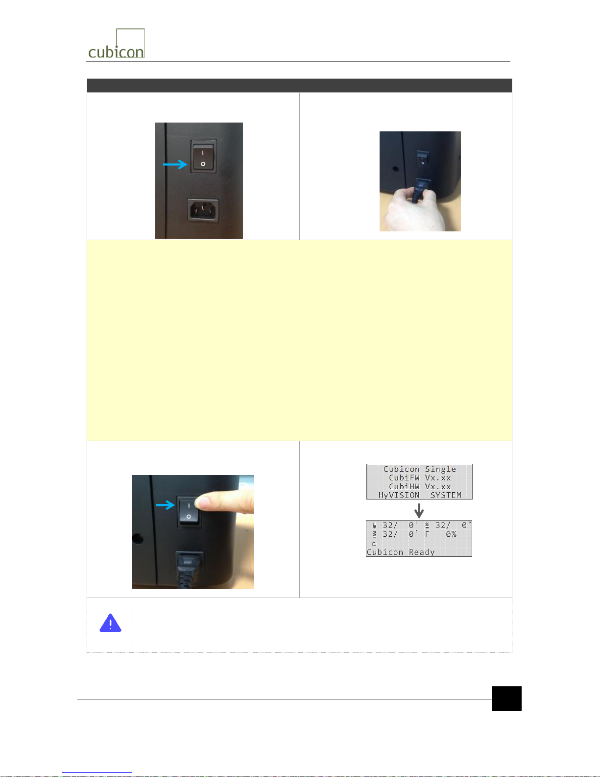
Turning on Printer
① Turn off (O position) the power switch on the rear of
the printer body.
② Push the power cable into the power input
connector on the printer body, arrange the power cable
so that it is not twisted, and push the power cable into
the socket.
Please double-check the following before you turn on the printer.
1) Eliminate any bending or twisting of the power cable; check the connection of the power cable to the
socket.
2) Confirm the mounting of the filament spool (with attention given to the spool rotation direction).
3) Check the proper movement of the Teflon tube.
- Confirm that the Teflon tube is in a slightly inclined position when the Teflon tube is inserted into the
filament insertion hole of the extruder and the extruder is pushed all the way to the left.
4) Check the condition of the extruder-driven cable.
- Confirm that there is no damage to the cable and that the extruder-driven cable is in appropriate
condition.
5) Confirm that the detachable extruder is properly mounted and fastened.
- Ensure it is fastened, as the fastening screws may be loosened during transport.
6) Confirm that the heating bed is mounted in the correct position.
- Ensure it is fastened, as the heating bed may have been moved during transport.
③ Turn on (l position) the power switch on the rear of
the printer body.
④ Check the LCD display.
* When you disconnect the power or USB cable, do not grip the cable part, but grip the
connector and pull it out.
* The USB cable is to connect to a PC to print from the PC or update the printer’s firmware. If
the printer is not connected to a PC, the USB cable does not need to be connected.
Unpacking and Installation (4/4)
Activation
Indication
Initial
* The figures on the screen will change according to the
surrounding temperature.
Page 10
Copyright Reserved HyVISION System Inc.
This document is the Quick Start Guide (141020,kr), and is subject to change without notice when necessary for
product improvements. HyVISION System does not take the responsibility for loss caused by any error in the
document or provisions and use of this document.
10
Emergency
Stop
The printer can be stopped immediately if there is a problem while
the printer is in operation.
Press the 【BACK】 and 【ENTER】 buttons simultaneously to
instantly stop the printer and reboot it (soft reboot)
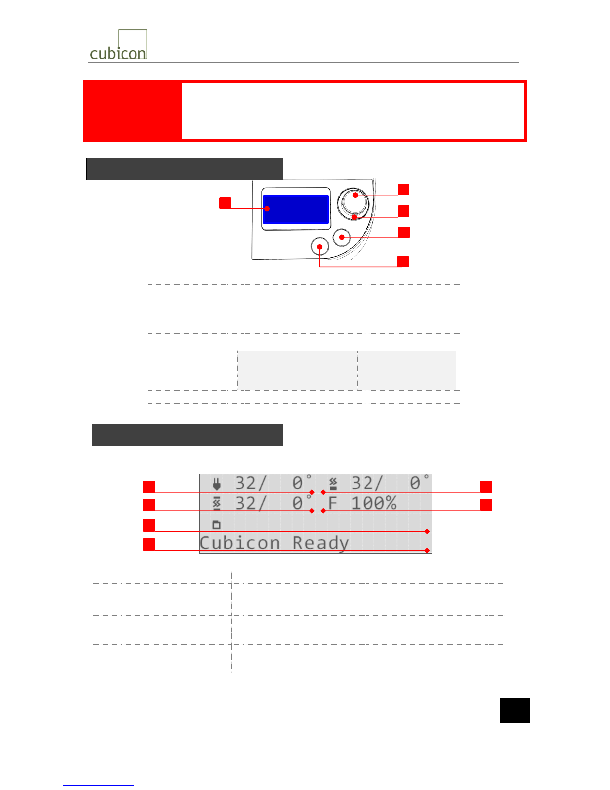
[1] LCD
Shows the current status or menu of the printer
[2]ENTER
button
- Launch the function menu
- Rotate Right/Left: Navigate among menus or change a
menu item
- Pressing: Select a menu or setting
[3]Status
lighting
Display printer statuses in different LED colors
Status
Being
heated
In
printing
Printing
Completed
Standby
Color
Red
Blue
Green
White
[4] BACK button
Move to the previous menu item
[5]HOME button
Move to the status display
When Cubicon Single is turned on or when the menu is not activated for functional setting, the current
printer status is shown on the LCD display.
[1] Extruder nozzle temperature
Current temperature/Target temperature
[2] Heating bed temperature
Current temperature/Target temperature
[3] Printer inside standby temp.
Current temperature/Target temperature
[4] Molding fan rotating speed
Rotating speed of the molding fan (max. 100%)
[5] File for output
Name of the output file in the SD card (in English)
[6] Printer operation status
Current printer operation status. If the printer is currently printing, the
current printing time (hh:mm) and progress rate are displayed.
1
3
5
6
2
4
ENTER
BACK HOME
1 2 3
4
5
LCD and Operating Buttons
LCD Display of Status
Printer Operation and LCD Display
Page 11
Copyright Reserved HyVISION System Inc.
This document is the Quick Start Guide (141020,kr), and is subject to change without notice when necessary for
product improvements. HyVISION System does not take the responsibility for loss caused by any error in the
document or provisions and use of this document.
11
This section describes the printing of an actual sample using the sample slicing file (G-code file) in the
supplied SD memory card after the printer is installed.
Before you print the sample, you are recommended to carefully read the latest operation manual
inside the SD card, or downloaded from Cubicon homepage (www.3dcubicon.com).
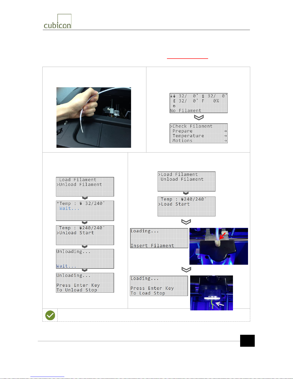
① Mount the filament spool to the spool carrier of the
printer and insert the filament all the way into the
Teflon tube inside the printer.
② Turn on the printer. Since there is no filament in the
extruder initially, “No Filament” is displayed.
Press the 【ENTER】 button to initiate the function
menu. “Check Filament” flickers.
③ Press “Check Filament”. ”Unload
Filament” is displayed, and the following
messages are displayed in sequence.
Set the temperature to 240℃.
④ Press the 【BACK】 button and select “Load filament”. The
following messages are displayed in sequence. Set the
temperature to 240℃.
During the loading process, filament with a different color from the mounted filament may
appear. This is residue from factory testing, and is normal.
Initial Printing (1/2)
Page 12
Copyright Reserved HyVISION System Inc.
This document is the Quick Start Guide (141020,kr), and is subject to change without notice when necessary for
product improvements. HyVISION System does not take the responsibility for loss caused by any error in the
document or provisions and use of this document.
12
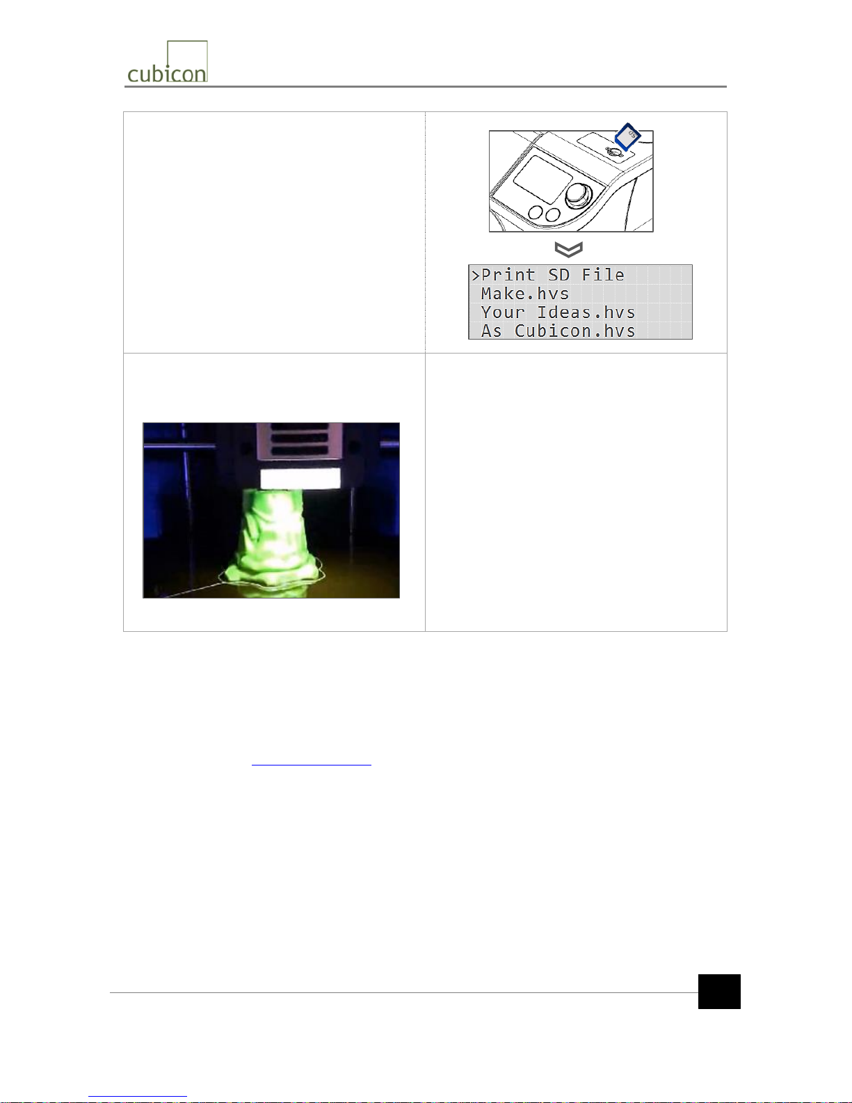
⑤ After loading, navigate to the {SD Card} menu by
pressing the 【BACK】 button.
Insert the supplied SD card into the SD memory
insertion hole and select the file to be output. You can
select a file from the G-Code (*.hvs) file list in the SD
card.
Select the “ABS_*.hvs” file if the mounted filament
is ABS and the “PLA_*.hvs” file if the mounted
filament is PLA.
Only the files with the extension *.hvs can be used for
printing. Files in other formats will not be printed.
⑥ Raise the heating bed temperature and extruder
temperature sequentially to the temperature conditions
recorded in the G-Code file, and run auto tilt of heating
bed in auto to begin printing.
⑦ When printing is completed, do not try to
forcibly separate the molded object, but wait until
the heating bed is cooled. The molded object can
be easily separated from the heating bed when the
temperature of the heading bed decreases to room
temperature.
If the molded part is not easily separated from the
heating bed even when the heating bed is cooled, it
will help if you make a space at the edge of the bottom
of the molded part with a flat object.
This document has described how to install the printer and print a sample.
Please carefully read the latest operation manual included in the SD card or downloaded from
Cubicon homepage (www.3dcubicon.com) before using the printer.
Thank you again for purchasing Cubicon Single!
Initial Printing (2/2)
 Loading...