

Page 1

Professional Shop Manual
Commercial Z-Wing
NOTE: These materials are for use by trained technicians who are experienced in the service and repair of outdoor power
equipment of the kind described in this publication, and are not intended for use by untrained or inexperienced individuals.
These materials are intended to provide supplemental information to assist the trained technician. Untrained or inexperienced individuals should seek the assistance of an experienced and trained professional. Read, understand, and follow all
instructions and use common sense when working on power equipment. This includes the contents of the product’s Operators Manual, supplied with the equipment. No liability can be accepted for any inaccuracies or omission in this publication,
although care has been taken to make it as complete and accurate as possible at the time of publication. However, due to
the variety of outdoor power equipment and continuing product changes that occur over time, updates will be made to these
instructions from time to time. Therefore, it may be necessary to obtain the latest materials before servicing or repairing a
product. The company reserves the right to make changes at any time to this publication without prior notice and without
incurring an obligation to make such changes to previously published versions. Instructions, photographs and illustrations
used in this publication are for reference use only and may not depict actual model and component parts.
© Copyright 2006 MTD Products Inc. All Rights Reserved
MTD Products Inc. - Product Training and Education Department
FORM NUMBER - 769-02102
1/2006
Page 2

Page 3

TABLE OF CONTENTS
Introduction ........................................................................................................................................... 1
Spindles and Blades ............................................................................................................................. 1
PTO Belt ................................................................................................................................................ 3
Deck Belt ............................................................................................................................................... 4
Spindle Service ..................................................................................................................................... 5
Deck Belt and PTO Belt Tensioner ........................................................................................................ 7
Cutting Deck Removal: Early 2005 Production ..................................................................................... 8
Cutting Deck Removal: Commencing with late 2005 Production ........................................................ 11
Deck Leveling: Early 2005 Production ................................................................................................ 13
Deck Wing and Hinge Lock .................................................................................................................16
Hinge Lock: Late 2005 production ......................................................................................................20
Deck Wing Lift Mechanism:Early 2005 Production ............................................................................. 24
Deck Wing Lift Cable Adjustment ........................................................................................................ 29
Deck Lift Mechanism ........................................................................................................................... 30
Lap Bars .............................................................................................................................................. 34
Checking Neutral Adjustment .............................................................................................................35
Linkage Neutral Adjustment ................................................................................................................36
Hydro Neutral Adjustment ................................................................................................................... 37
Tracking Adjustment ........................................................................................................................... 38
Steering Pivot Shafts and Bushings .................................................................................................... 40
Brake Linkage Adjustment ..................................................................................................................41
Brake Pivot Shaft Removal .................................................................................................................46
Hydraulic Drive System: General Operation ....................................................................................... 48
Hydraulic Drive System: Diagnosis ..................................................................................................... 50
Hydraulic Drive System: Pump Removal ............................................................................................54
Hydraulic Drive System: Wheel Motor Removal ................................................................................. 58
Front Axle and Caster Wheels ............................................................................................................ 61
Electrical: Components ....................................................................................................................... 66
Electrical: Starter Circuit ......................................................................................................................73
Electrical: Engine Stop Circuit .............................................................................................................74
Electrical: Engine-Stopping Safety Circuits .........................................................................................75
Electrical: PTO Circuit .........................................................................................................................76
Electrical: Deck Wing Lift .................................................................................................................... 77
Electrical: Charging Circuit .................................................................................................................. 78
Charging System Diagnosis ................................................................................................................ 78
Resistance ..........................................................................................................................................80
1
Page 4

2
Page 5
1. INTRODUCTION
Cub Cadet Commercial Z-Wing
Cub Cadet Commercial Z-Wing
1.1. Purpose: Heavy-duty mowing in a compact
package.
• Until now, commercial cutters needing a
machine that would fit through a 36” gate had to
settle for a commercial walk-behind mower or a
homeowner-grade zero-turn.
• The Z-Wing’s unique folding deck gives it the
ability to pass through a 36” gate or opening, yet
provide a 48” cutting swath, increasing productivity.
• When folded, the deck wings of the Z-Wing takeup a smaller foot-print in a trailer or garage. This
enables the user to make more efficient use of
their trailer and garage space, and reduces the
chance of damage to other equipment during
loading or storage.
NOTE: When the deck of our standard TANK
line encounters other objects, it is seldom the
deck that gets damaged.
1.2. Means: The deck wings are lifted by an electric
actuator pulling on cables.
1.3. Safety: Safety switches that sense the position
of the deck wings prevent the PTO from being
engaged while the wings are up.
1.4. Drive System: Hydro-gear pumps drive White
Hydraulic wheel motors. These motors are new
to Cub cadet, and feature a unique roller stator
design.
See Figure 1.1.
Figure 1.1
NOTE: The information in this manual is derived
from prototype equipment. Although it is accu
rate at the time of writing, it is subject to change
without notice.
2. SPINDLES AND BLADES
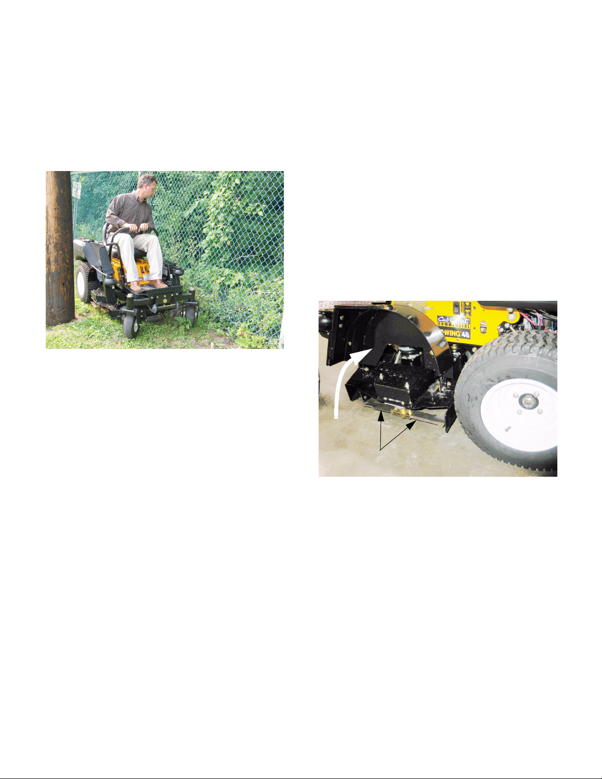
2.1. Flail blades have been in use on “bat-wing”
mowers in a variety of applications for many
years. The unique thing about their use on the
Z-Wing mower is that they enable just the outer
portion of the deck (wing) to be raised, and the
blades fold back to clear obstacles while the
wings are raised.
Deck wing
(raised)
Blades
2.2. Things to know about flail blades:
• The individual blade elements can be removed
from each of the three blade assemblies.
• If one element on a blade assembly is worn or
damaged beyond a point that can be corrected
with a light sharpening, replace both elements to
maintain balance.
• Blade assemblies can be balanced, but not with
the ease nor the accuracy of single-piece
blades.
• Replace any suspect blade hardware before
operating the mower.
• The operator should cease operation immediately if any unusual deck vibration or noises
occur.
See Figure 2.1.
Figure 2.1
-
1
Page 6
Cub Cadet Commercial Z-Wing
2.3. Precautions:
• Disable the engine while working on the cutting
deck: Disconnect the sparkplug leads, disconnect the negative battery cable, and remove the
key from the key switch.
• Allow the engine to cool thoroughly before working near the exhaust system.
• Protect hands while working on sharp objects
like blades using gloves or rags.
2.4. With the wings raised the outer blades are easily
accessible for service. The center blade is as
accessible as it would be on a conventional
deck. Lift and safely support the mower to reach
the center blade.
See Figure 2.4.
2.6. When performing any blade or spindle service,
inspect the spindles, pulleys, and belts for wear
or damage.
2.7. Inspect the hardware that secures the blades to
the blade mount assemblies.
• Replace the locking nut if the locking feature has
degraded.
• If the bolt is replaced, use only a grade-8
replacement from a reputable source (Cub
Cadet).
• Replace the bushing if it shows signs of wear or
damage.
2.8. On installation, apply a small amount of thread
locking compound such as Loctite 262 (red) to
the threads, and tighten the nuts to a torque of
35-40 ft-lbs (47.5-54 Nm).
2.9. If the blade assembly is to be removed for sharpening and balancing, lower the deck to the lowest cutting position.
2.10. Remove the belt covers using a 9/16” wrench.
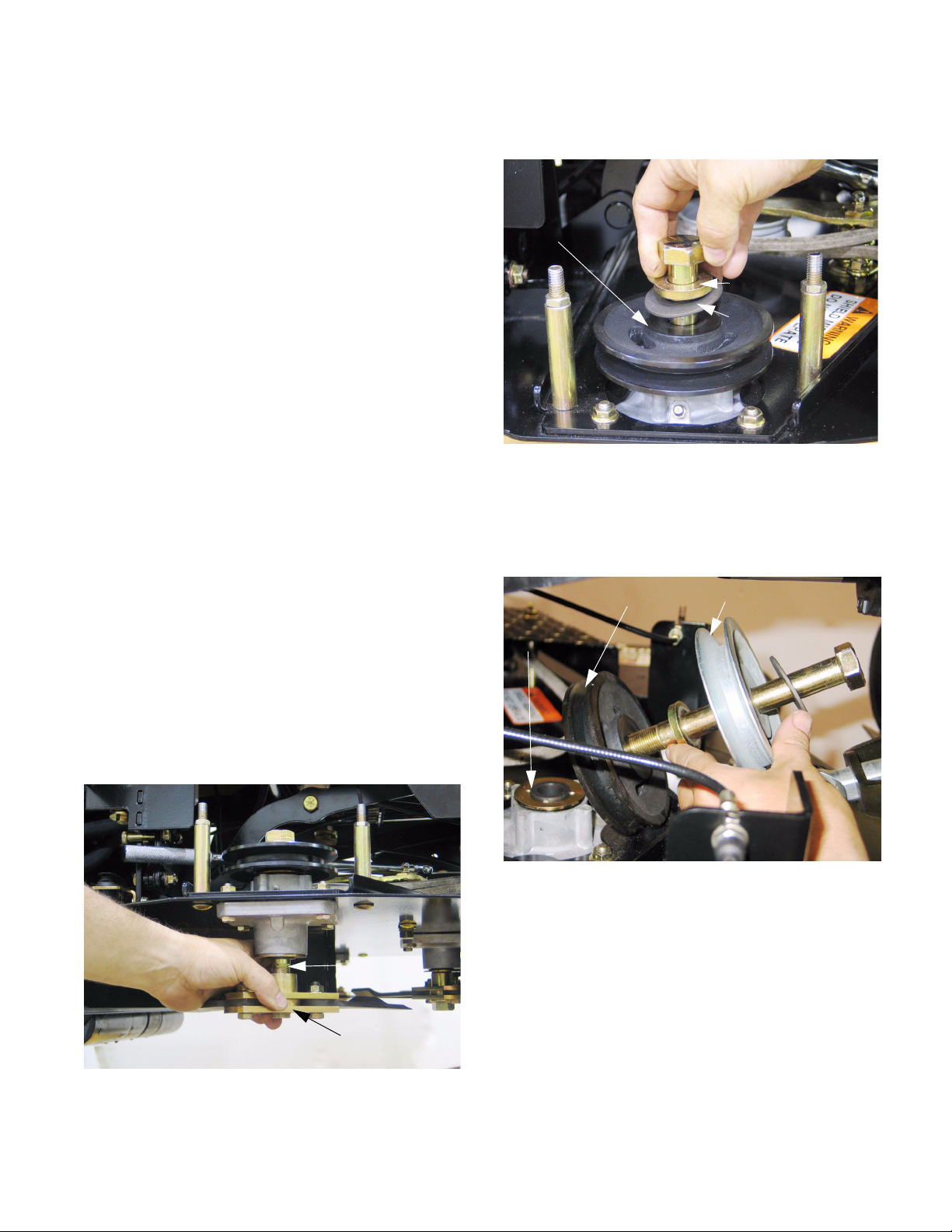
2.11. Hold the top of the spindle bolt using a 1 1/8”
wrench and turn the nut off the bottom using a
1 1/8” wrench.
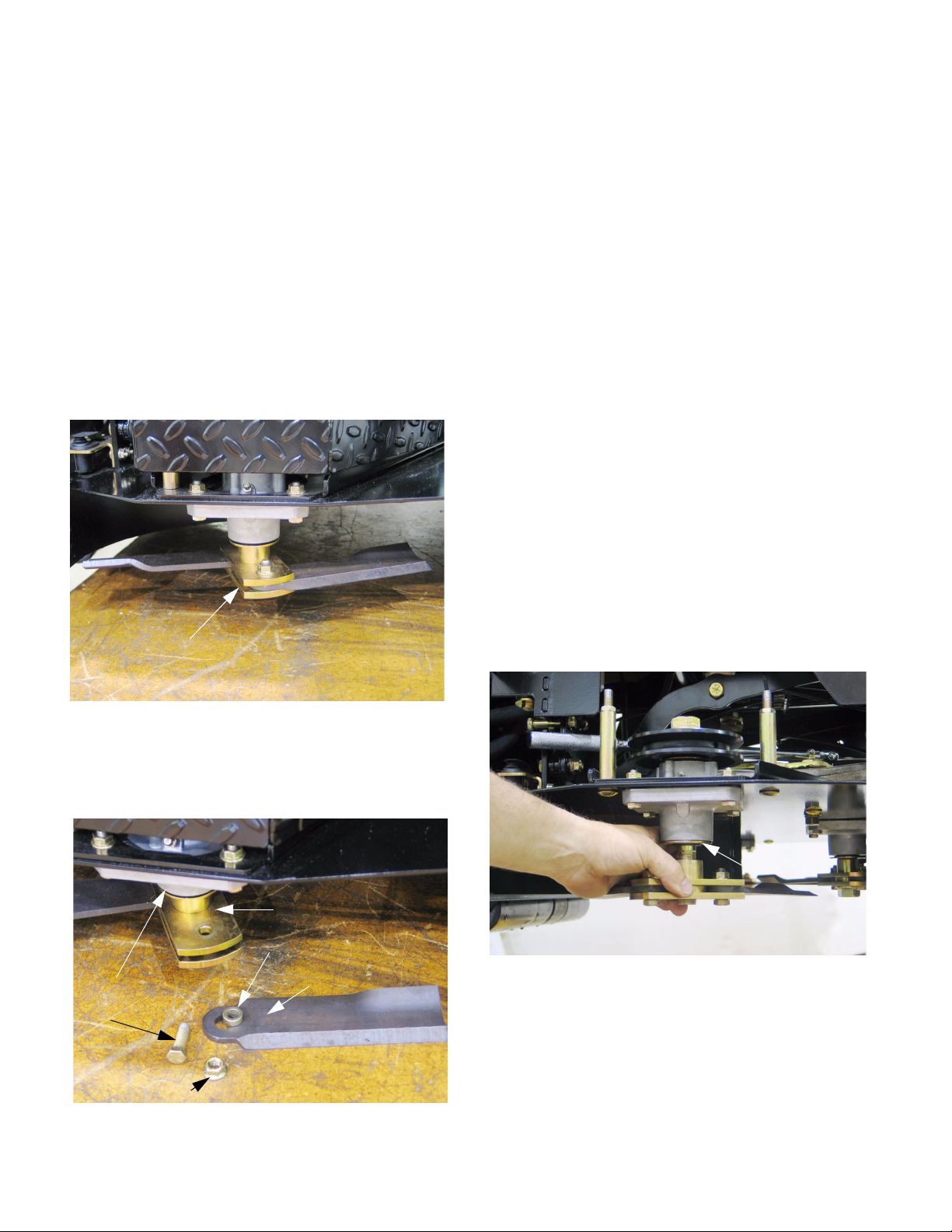
Blade assembly in-place
Figure 2.4
2.5. The blades can be removed from the blade
mount assembly using a pair of 9/16” wrenches.
See Figure 2.5.
Blade spacer
and upper mounting plate
Bushing
Steel shield
Grade-8 bolt
Blade
2.12. Slide the blade assembly off the spindle bolt.
See Figure 2.12.
Steel shield
Figure 2.12
NOTE: The steel shield is part of the seal, not
the blade assembly. Do not remove it unless the
spindle requires service.
Self-locking nut
Figure 2.5
2
Page 7
Cub Cadet Commercial Z-Wing
2.13. The blade assemblies may be sharpened and
balanced similar to conventional blades, but a
straight-edge should be used to confirm that the
blades are straight out. If the blades are partially
folded during balance checking, the results will
be thrown-off.
2.14. On installation, apply thread locking compound
such as Loctite 262 (red) to the threads, and
tighten the nut to a torque of 100-120 ft-lbs (114136 Nm).
2.15. Install the belt covers and reconnect the battery.
2.16. Test the operation of the mower and its safety
features before returning it to service.
3. PTO BELT
3.1. Precautions:
• Disable the engine while working on the cutting
deck: Disconnect the sparkplug leads, disconnect the negative battery cable, and/or remove
the key from the key switch.
• Allow the engine to cool thoroughly before working near the exhaust system.
• Protect hands while working on sharp objects
like blades using gloves or rags.
• Apply the parking brake while working on the
mower.
3.2. Lower the deck wings.
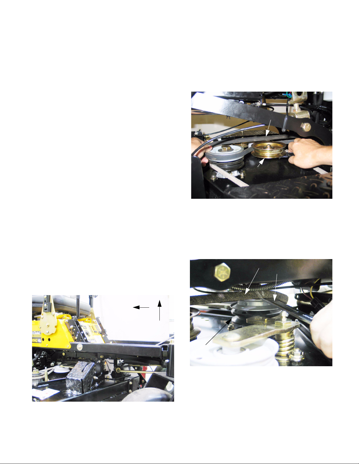
3.3. Raise the cutting deck to the highest position.
This moves the deck as far back as possible,
reducing the amount of force on the PTO belt
tensioner.
See Figure 3.3.
3.4. Remove the belt covers that protect the blade
spindles using a 9/16” wrench.
3.5. Working from the left side of the mower, relieve
tension from the belt tensioner pulley, and roll
the belt off of the pulley, allowing the tensioner
pulley to slip beneath the belt.
PTO belt
PTO belt tensioner pulley
Figure 3.5
NOTE: belt routing and spring location
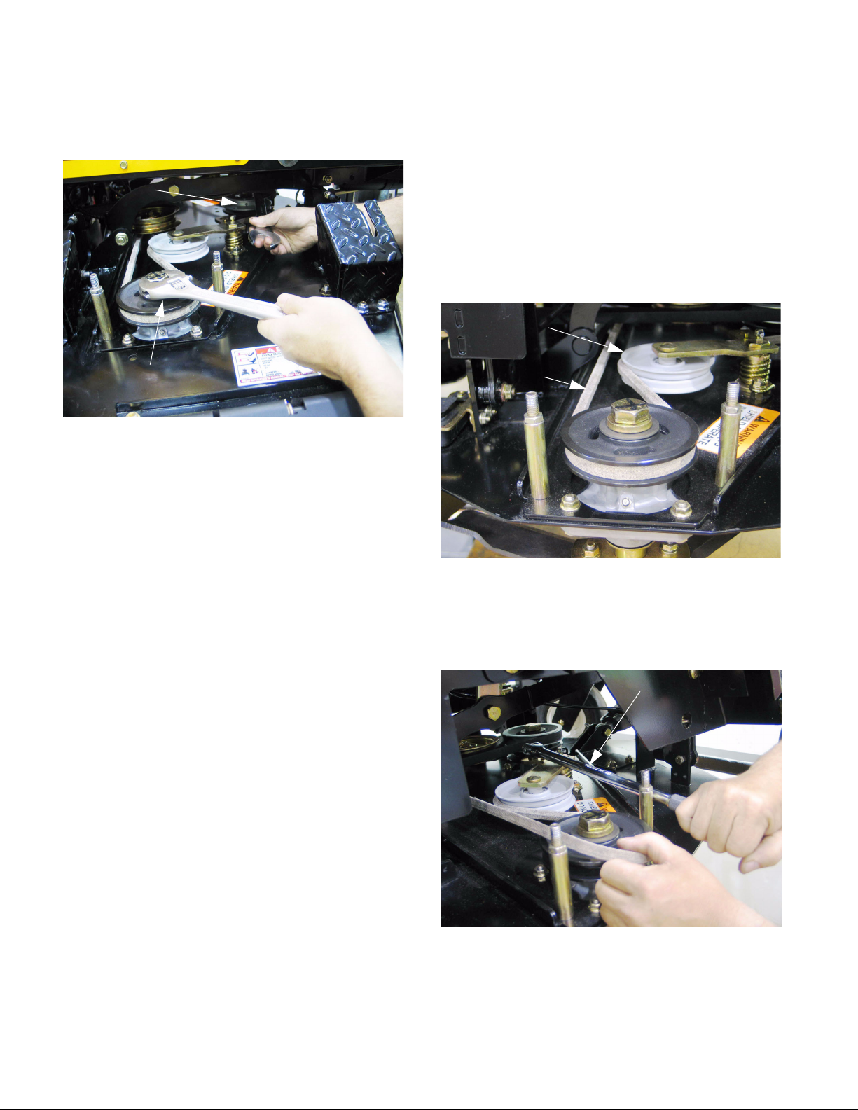
3.6. With the tension relieved, connect a 1 1/8”
wrench to the bolt at the top of the stack pulley.
Pass the wrench beneath the belt to reach the
bolt.
See Figure 3.6.
PTO Belt
See Figure 3.5.
1 1/8” wrench
Deck moves back
as deck moves up
Loosening belt slightly
Figure 3.3
Stack pulley
Figure 3.6
3.7. Draw the wrench forward to force the belt over
the top of the pulley.
3
Page 8
Cub Cadet Commercial Z-Wing
3.8. A second 1 1/8” wrench may be applied to the
top of the nearest blade spindle if more rotation
is needed.
Stack pulley
Second wrench on
near pulley
3.9. Lower the deck slightly to provide belt clearance
between the stack pulley and the wing lift motor,
and remove the belt from the mower.
See Figure 3.8.
Figure 3.8
4. DECK BELT
4.1. Remove the PTO belt as described in the PTO
Belt section of this manual, including all precau
tions.
4.2. Remove both deck belt covers using a 9/16”
wrench.
4.3. Working from the right of the mower, use a 1/2”
breaker bar to move the deck belt tensioner pul
ley arm, relieving tension from the deck belt.
See Figure 4.3.
Deck belt tensioner pulley
Deck belt
-
-
3.10. If the old belt exhibits any damage beyond normal wear, identify and correct the cause of the
damage before returning the mower to service.
3.11. Inspect the condition of the deck belt, and
replace it if it is suspect.
3.12. Position the new belt on the PTO clutch and
stack pulley.
3.13. Pull the tensioner pulley arm out to the left, and
slip the belt over the pulley.
3.14. Test the operation of the mower deck before
returning the mower to service.
Figure 4.3
NOTE: belt routing and spring location
4.4. Roll the belt off of the tensioner or s p i n d l e p u l l e y .
See Figure 4.4.
1/2” Breaker bar
Figure 4.4
4.5. If the old belt exhibits any damage beyond normal wear, identify and correct the cause of the
damage before returning the mower to service.
4
Page 9
Cub Cadet Commercial Z-Wing
4.6. Check the blade spindles for looseness while the
belt is off.
4.7. Reverse the removal process to install a new
belt or belts.
4.8. Test the operation of the mower and its safety
features before returning the mower to service.
5. SPINDLE SERVICE
5.1. Inspect all of the spindles for wear or damage
when performing regular deck belt and blade
maintenance. The recommended lubrication
interval for the deck spindles is 25 hrs., using
No.2 Multipurpose lithium base grease.
5.2. If repair or removal is required, remove the deck
belt as described in the Deck Belt section of this
manual.
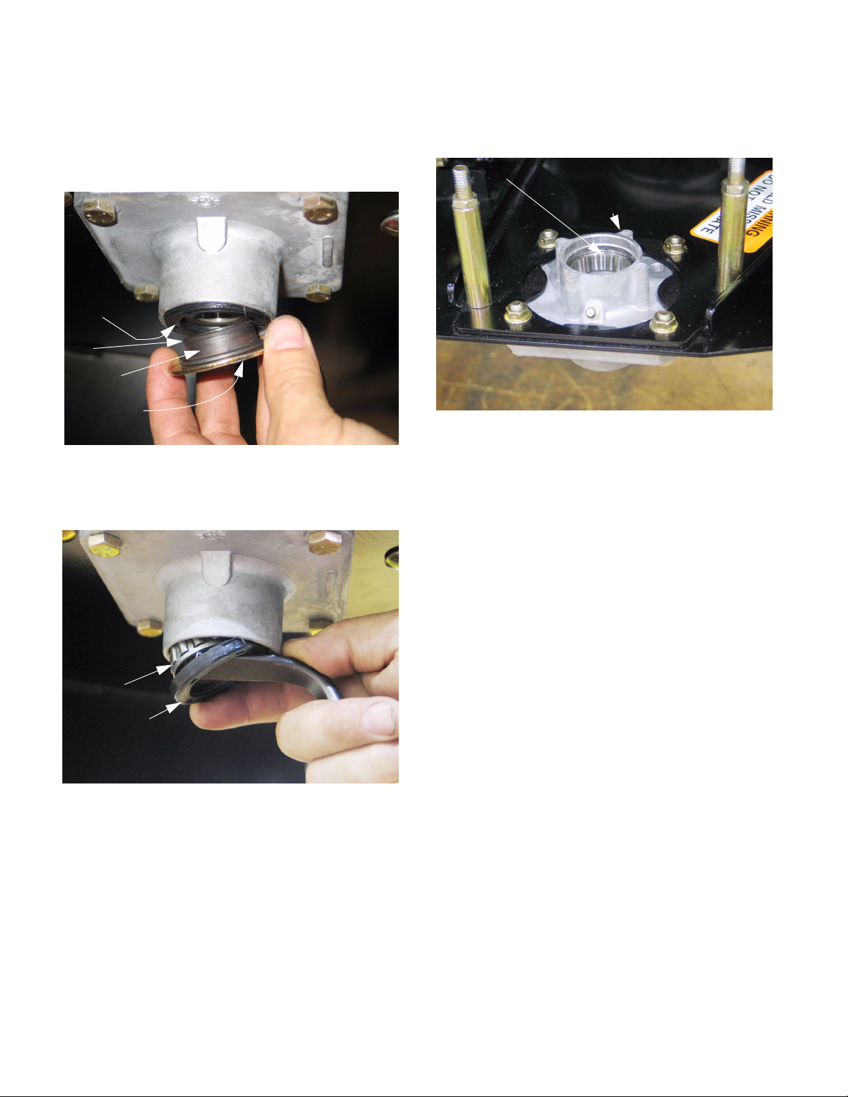
5.5. Withdraw the spindle bolt and washers, and
remove the pulley.
Thick hub boss
faces up on all
spindle pulleys
Figure 5.5
5.6. The center spindle has two pulleys, with a
spacer between them, but the procedure is oth
erwise similar to the outer two spindles.
See Figure 5.6.
Deck belt sheave PTO belt sheave
Steel shield
(top)
See Figure 5.5.
Heavy washer
Flat washer
-
5.3. Hold the top of the spindle bolt using a 1 1/8”
wrench and turn the nut off the bottom using a
1 1/8” wrench.
5.4. Slide the blade assembly off the spindle bolt.
See Figure 5.4.
Spindle bolt
Blade assembly
Figure 5.4
Figure 5.6
5.7. Once the pulley is removed, the spindle may be
unbolted from the deck using a pair of 9/16”
wrenches, or it may be repaired in place.
NOTE: If a warrantable repair is being made to
the spindle, replace the spindle as a complete
unit. Outside of warranty, the dealer may repair
or replace the spindle at their own discretion.
Spindle service parts may not be available dur
ing the first year of production.
-
5
Page 10
Cub Cadet Commercial Z-Wing
5.8. The steel shields are identical top and bottom,
and are easily removable. They do have barbed
lips that may damage the seal when removed.
they should not be removed unless the seals are
to be replaced.
Seal
Lip
Sealing surface
Steel shield
5.9. With the steel shields removed, the seals and
bearings also come out easily.
See Figure 5.8.
Figure 5.8
See Figure 5.9.
5.10. If the tapered roller bearings need to be
replaced, the races need to be driven-out and
replaced as well.
Race (upper spindle bearing)
Spindle housing
5.11. Assembly notes:
• Clean and inspect the bearings for signs of damage. Replace bearings and races if necessary.
• Pack the bearings with fresh No.2 multi-purpose
lithium base grease and install them in the spindle housings using new seals.
See Figure 5.10.
Figure 5.10
Tapere d
roller bearing
Seal
• Replace any suspect hardware.
• On installation of the spindle nuts, apply thread
locking compound such as Loctite 262 (red) to
the threads, and tighten the nut to a torque of
100-120 ft-lbs (114-136 Nm).
• Apply a small amount of thread locking compound such as Loctite 242 (blue), or replace the
nuts if the locking feature of the nuts are in question. Tighten the spindle mounting bolts (nuts) to
a torque of 20-25 ft-lbs (27-34 Nm).
Figure 5.9
6
Page 11
Cub Cadet Commercial Z-Wing
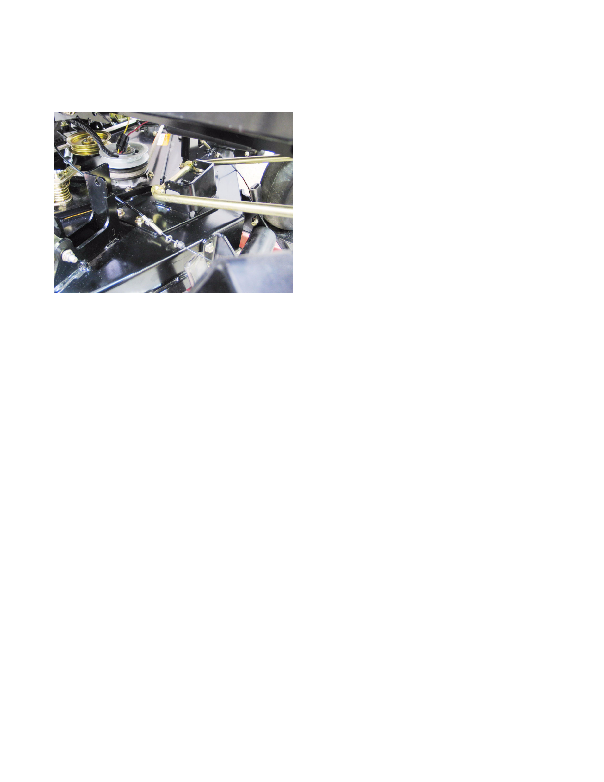
6. DECK BELT AND PTO BELT TENSIONER
6.1. The deck belt tensioner idler arm can be
removed using a 1” wrench on the bolt head
above the deck and an 11/16” wrench to remove
the nut, lock washer, and flat washer from
beneath the deck.
Deck belt
tensioner arm
Figure 6.1
6.2. The bolt is rifle-drilled to provide for grease
access to the bushing in the idler arm. The bush
ings are replaceable. See Figure 6.2.
See Figure 6.1.
Torsion spring
Heavy flat washer
Shoulder bolt (drilled)
6.5. The pulley is mounted to the idler arm using a
carriage bolt. It can be easily removed using a 9/
16” wrench.
6.6. Installation notes:
• Apply a small amount of thread locking compound such as Loctite 262 (red) to the torsion
spring retaining nut, or replace the nut if the locking feature of the nut is in question. Snug the nut
against the spring.
• Apply a small amount of thread locking compound such as Loctite 242 (blue), or replace the
nuts if the locking feature of the nuts are in question. Tighten the pulley mounting nut to a torque
of 20-25 ft-lbs (27-34 Nm).
• Apply a small amount of thread locking compound such as Loctite 242 (blue), or replace the
nut if the locking feature of the nut is in question.
Tighten the idler arm bolt to a torque of 30-35 ftlbs (41-48 Nm).
• Lubricate the idler arm bushings with #2 multipurpose lithium base grease.
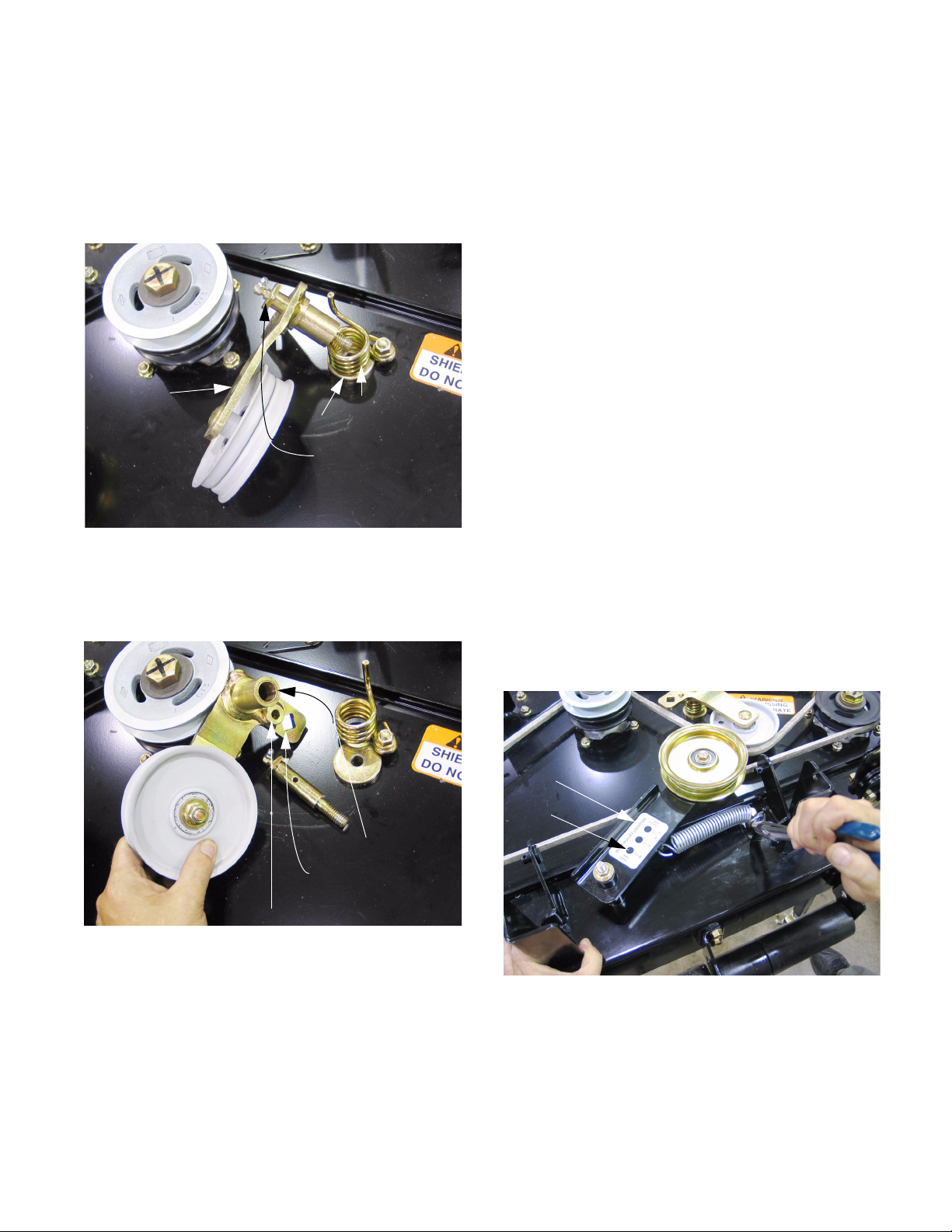
6.7. The PTO belt tensioner is a simple idler arm with
an extension spring between the arm and the
-
deck weldment.
6.8. The spring may be detached without removing
the arm using a length of starter rope or a spring
removal tool.
See Figure 6.8.
Bushing
Hole for breaker bar
Hole for torsion spring
Figure 6.2
6.3. A heavy flat washer between the shoulder of the
bolt and the deck weldment distributes the
mounting load.
6.4. The torsion spring is mounted to a carriage bolt
using a nut and jam nut that can be easily
removed using a 9/16” wrench.
Label
“48”
Figure 6.8
6.9. The PTO idler arm can be removed from the
deck using two 9/16” wrenches.
7
Page 12
Cub Cadet Commercial Z-Wing
6.10. There are three mounting holes for the pulley on
the idler arm, use the one nearest the pivot point
as indicated by the “48” mark on the label.
See Figure 6.10.
Mounting holes
Figure 6.10
6.11. The bushings in the PTO belt tensioner idler arm
are replaceable.
7. CUTTING DECK REMOVAL: EARLY 2005 PRODUCTION
NOTE: Decks having U-shaped front lift rods
were used on all Z-Wings produced after Nov. 1,
2005 (S/N: 0K015Z00001). These decks are ret
rofitted to earlier production. Earlier decks are
easily identified by V-shaped front lift rods that
connect to the deck at a single point.
7.1. Remove the PTO belt as described in the PTO
Belt section of this manual, including all precau
tions.
7.2. Trap the deck lift in the lowest position using the
clevis pin so that the cutting deck rests on the
ground and the lift handle does not imitate a cat
apult when the weight of the deck is removed
from the lift assist springs.
Lift handle
See Figure 7.2.
-
-
-
6.12. Assembly notes:
• Apply a small amount of threadlocking compound such as Loctite 242 (blue), or replace the
nuts if the locking feature of the nuts are in question. Tighten the pulley mounting nut to a torque
of 20-25 ft.-lbs (27-34 Nm).
• Apply a small amount of threadlocking compound such as Loctite 242 (blue), or replace the
nut if the locking feature of the nut is in question.
Tighten the pulley mounting nut to a torque of
20-25 ft.-lbs (27-34 Nm).
• Lubricate the idler arm bushings with No. 2 multipurpose lithium base grease.
Clevis pin
Figure 7.2
8
Page 13
Cub Cadet Commercial Z-Wing
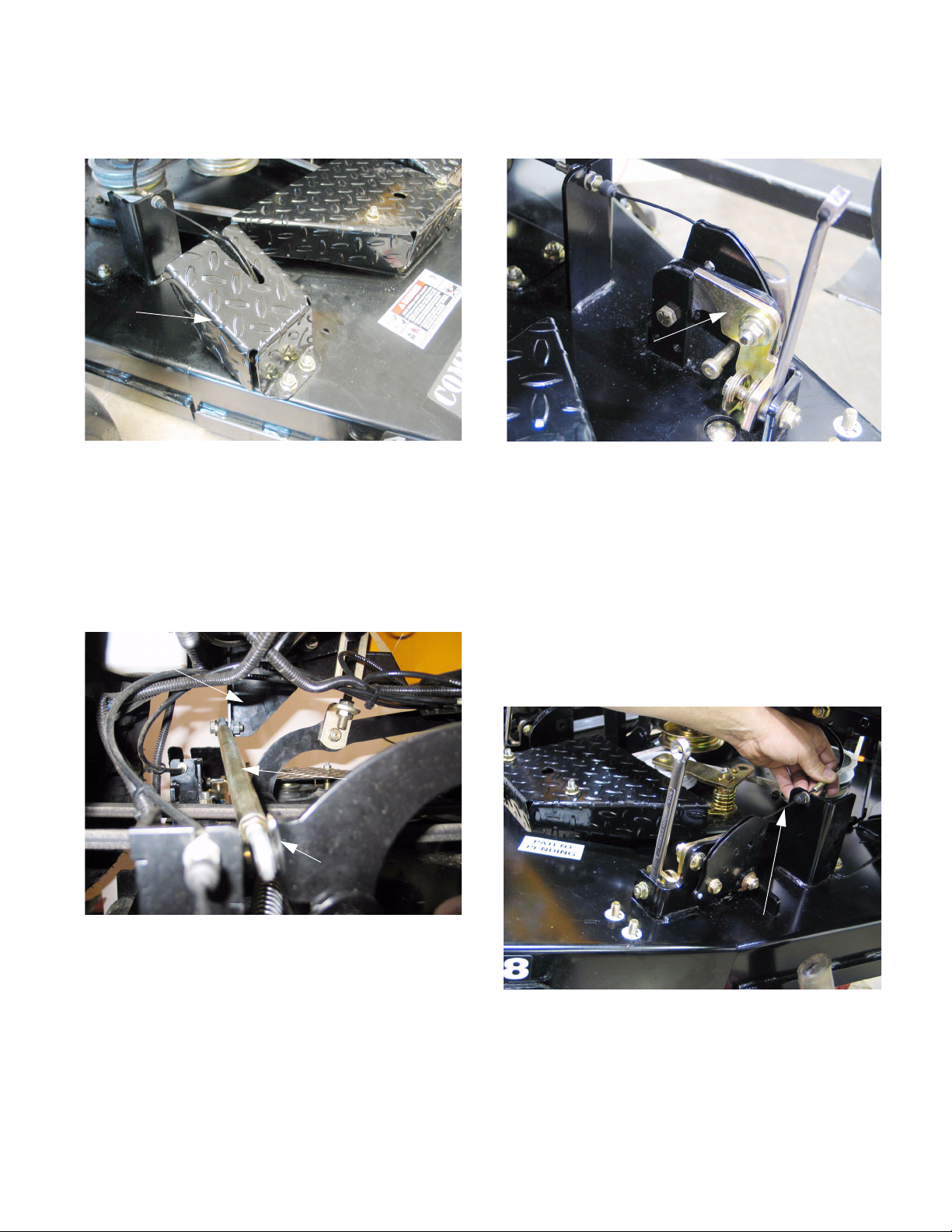
7.3. Remove the wing lift shield using a 9/16”
wrench.
Wing lift
shield
7.4. Mowers produced after mid-season 2005 (2005/
2) are equipped with a lateral brace between the
frame and the mowing deck, similar to a panhard
rod in the rear suspension of a car or truck. Dis
connect or remove the lateral brace as required
by the task at-hand using a 5/8” wrench and an
11/16” wrench.
Frame
mounting point
See Figure 7.3.
Figure 7.3
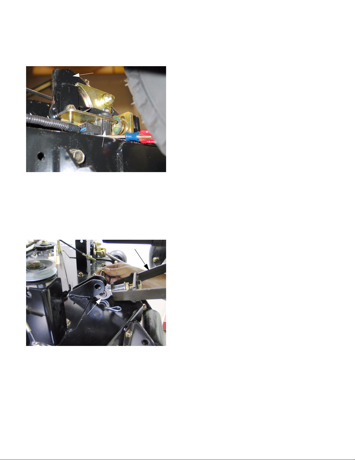
See Figure 7.4.
7.5. Block all four hinge locks into the unlatched position using extra wrenches. See Figure 7.5.
Hinge lock
Figure 7.5
NOTE: Wrenches are handy to insert, easy to
spot, and unlikely to be forgotten.
-
7.6. Slide the rubber boot back from the cable end,
and remove the end jam nut on the cable using a
pair of 1/2” wrenches.
7.7. With the wings unlatched, they can be lifted
manually. Lift the wings manually to put slack in
the lift cable so that the end of the cable can be
slipped-out of the hole and slot in the bracket.
See Figure 7.7.
Figure 7.4
lateral link
Deck
mounting point
Lift wing to provide
slack in the cable
Figure 7.7
7.8. Once the cable housing is released from the
bracket on the deck, the barrel on the end of the
cable core can be maneuvered out of the hole
and slot in the wing lift bracket.
9
Page 14
Cub Cadet Commercial Z-Wing
7.9. Disconnect the wires from the deck wing position
switches on each rear deck wing bracket.
See Figure 7.9.
Rear deck wing hinge
Deck Wing position switch
Figure 7.9
7.10. Cut any cable ties holding wing lift cables and
wing position switch wires to the cutting deck.
7.11. Remove the hairpin clip and clevis pin that
secure the front of the cutting deck to the spheri
cal rod end on the front lift arm assembly.
See Figure 7.11.
Front lift arm Ass’y.
• Hold the lift handle down
• Carefully remove the hairpin clip and clevis pin
that kept the lift handle in the lowest position.
• Carefully allow the lift handle to rise to the transport position under the force of the lift assist
springs.
• Turn the front caster wheels sideways for deck
clearance.
7.15. Remove the cutting deck from the mower.
7.16. Installation is done by reversing the removal process. Installation notes:
• Confirm the correct operation of all safety features, including the wing-latch mechanisms
before returning the mower to service.
• Confirm that the cables ar correctly adjusted
after deck installation.
• Confirm that the cables and wires are routed and
fastened in such a way that they will not be damaged during operation of the mower.
• If the locking feature of the removed lateral
-
brace mounting nut has worn, replace the nut or
apply a small amount of thread locking compound such as Loctite 242 (blue).
• Tighten the mounting bolt to a torque of 40 ft-lbs.
(54.25 Nm).
Spherical rod end
Figure 7.11
7.12. Remove the hairpin clips that secure the cutting
deck to the lift arms.
NOTE: 914-0147 hairpin clips are an acceptable
replacement for the originals.
7.13. Move the deck to the right to disengage the pins
that connect the deck to the lift arms.
7.14. If working on the ground:
10
Page 15
Cub Cadet Commercial Z-Wing
8. CUTTING DECK REMOVAL: COMMENCING WITH LATE 2005 PRODUCTION
NOTE: Decks having U-shaped front lift rods
were used on all Z-Wings produced after Nov. 1,
2005 (S/N: 0K015Z00001). These decks are ret
rofittable to earlier production. Earlier decks are
easily identified by V-shaped front lift rods that
connect to the deck at a single point.
8.1. Remove the PTO belt as described in the PTO
Belt section of this manual, including all precau
tions.
8.2. Trap the deck lift in the lowest position using the
clevis pin so that the cutting deck rests on the
ground or a purpose-built cart, and the lift handle
does not imitate a catapult when the weight of
the deck is removed from the lift assist springs.
See Figure 8.2.
Lift handle
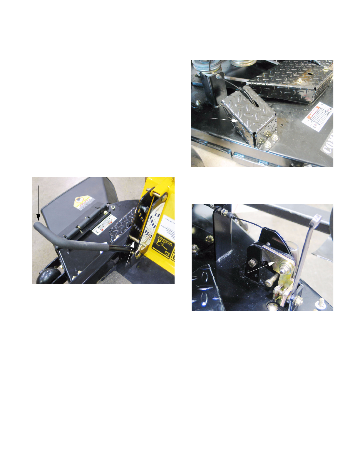
8.3. Remove the wing lift shield using a 9/16”
wrench.
-
-
Wing lift
shield
8.4. Block all four hinge locks into the unlatched position using extra wrenches. See Figure 8.4.
See Figure 8.3.
Figure 8.3
Figure 8.2
Clevis pin
Hinge lock
Figure 8.4
NOTE: Wrenches are handy to insert, easy to
spot, and unlikely to be forgotten.
8.5. Slide the rubber boot back from the cable end,
and remove the end jam nut on the cable using a
pair of 1/2” wrenches.
11
Page 16
Cub Cadet Commercial Z-Wing
8.6. With the wings unlatched, they can be lifted
manually. Lift the wings manually to put slack in
the lift cable so that the end of the cable can be
slipped-out of the hole and slot in the bracket.
See Figure 8.6.
Lift wing to provide
slack in the cable
Figure 8.6
8.7. Once the cable housing is released from the
bracket on the deck, the barrel on the end of the
cable core can be maneuvered out of the hole
and slot in the wing lift bracket.
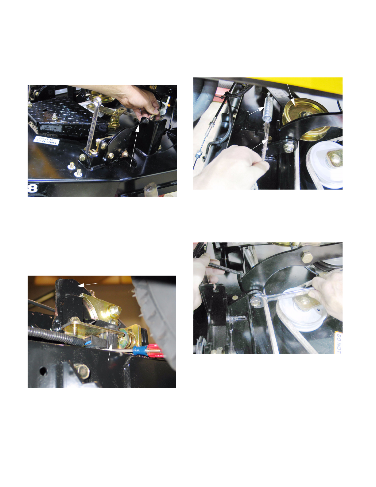
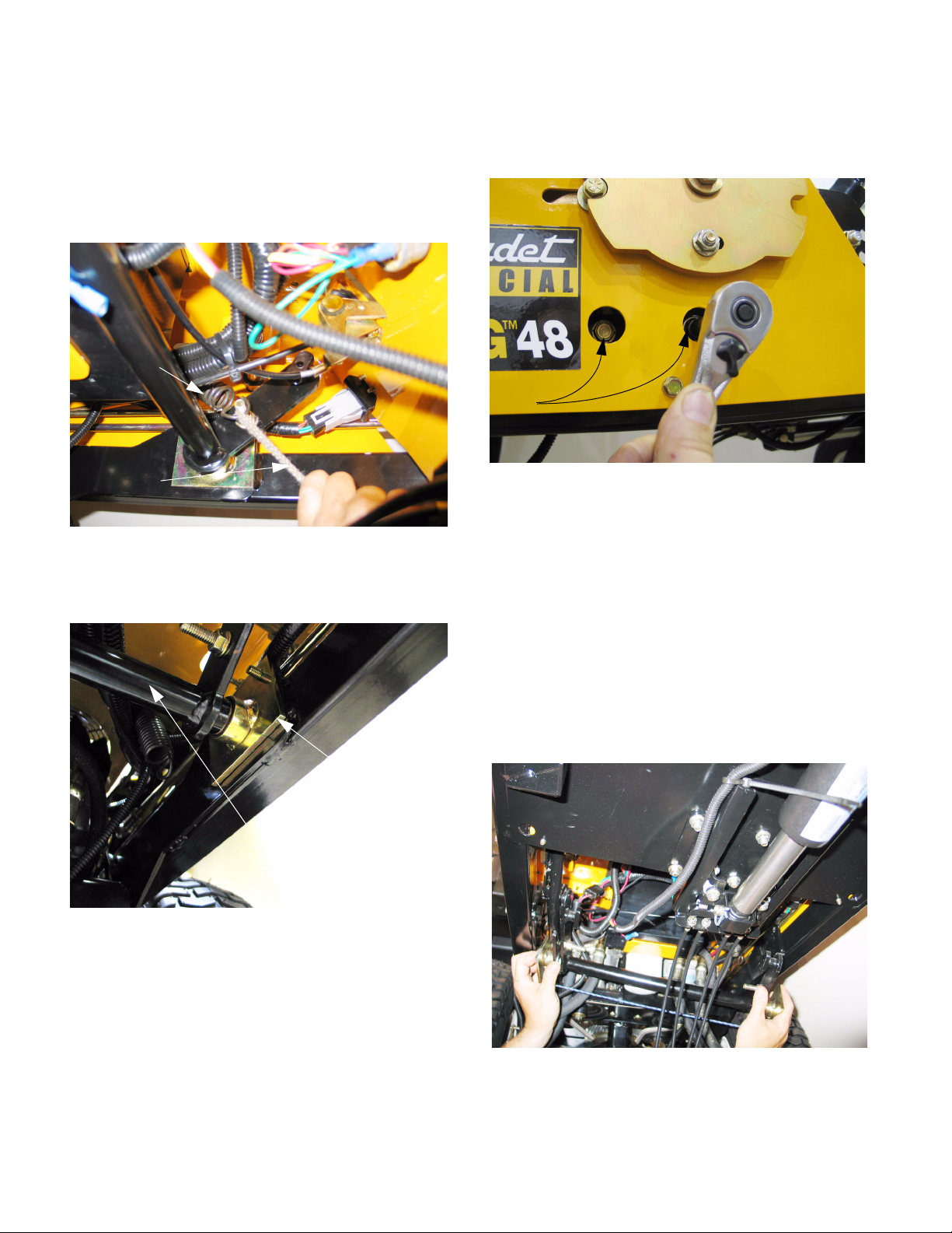
8.10. Release the extension spring that maintains tension on the PTO belt tension arm and pulley.
Use a length of starter rope or a spring removal
tool.
Extension
spring
Bolt
(anchor point
for spring)
Figure 8.10
8.11. Remove the nuts and socket-head shoulder
bolts that connect the deck to the lift arms using
a 5/16” Allen wrench and a 3/4” wrench.
See Figure 8.11.
See Figure 8.10.
PTO belt tensioner pulley
8.8. Disconnect the wires from the deck wing position
switches on each rear deck wing bracket.
See Figure 8.8.
Rear deck wing hinge
Deck Wing position switch
Figure 8.8
8.9. Cut any cable ties holding wing lift cables and
wing position switch wires to the cutting deck.
Figure 8.11
12
Page 17
Cub Cadet Commercial Z-Wing
8.12. Move the deck forward to disengage the front
deck lift bar from the hooks on the front of the
deck.
See Figure 8.12.
Figure 8.12
8.13. Raise the mower and remove the deck from
beneath it.
8.14. If working on the ground:
8.16. Installation is done by reversing the removal process. Installation notes:
• Confirm the correct operation of all safety features, including the wing-latch mechanisms
before returning the mower to service.
• Confirm that the cables ar correctly adjusted
after deck installation.
• Confirm that the cables and wires are routed and
fastened in such a way that they will not be damaged during operation of the mower.
• If the locking feature of the removed laterally
brace mounting nut has worn, replace the nut or
apply a small amount of thread locking compound such as Loctite 242 (blue).
• Tighten the mounting bolt to a torque of 40 ft-lbs.
(54.25 Nm).
• Hold the lift handle down
• Carefully remove the hairpin clip and clevis pin
that kept the lift handle in the lowest position.
• Carefully allow the lift handle to rise to the transport position under the force of the lift assist
springs.
• Turn the front caster wheels sideways for deck
clearance.
• Remove the cutting deck from the mower.
8.15. If the mower is to be moved while the cutting
deck is off of it:
• Secure the wires and cables that are associated
with the wing lift mechanism.
• Secure or remove the front lift bar assembly.
9. DECK LEVELING: EARLY 2005 PRODUCTION
NOTE: Decks having U-shaped front lift rods
were used on all Z-Wings produced after Nov. 1,
2005 (S/N: 0K015Z00001). These decks are ret
rofittable to earlier production. Earlier decks are
easily identified by V-shaped front lift rods that
connect to the deck at a single point.
9.1. Preparation:
• Park the mower on a flat, level, paved surface,
set the parking brake and lower the deck wings.
• Safety: disable the engine by removing the key
from the key switch and disconnecting the high
tension leads from the spark plugs.
• Setting the mower deck height to 4” provides the
best combination of access above and below the
deck.
-
• Check the rear tire pressure: they should be
between 10-12 PSI (.69-.84 Bar). Be aware that
adjustments to rear tire pressure will also cause
a change in tracking.
13
Page 18
Cub Cadet Commercial Z-Wing
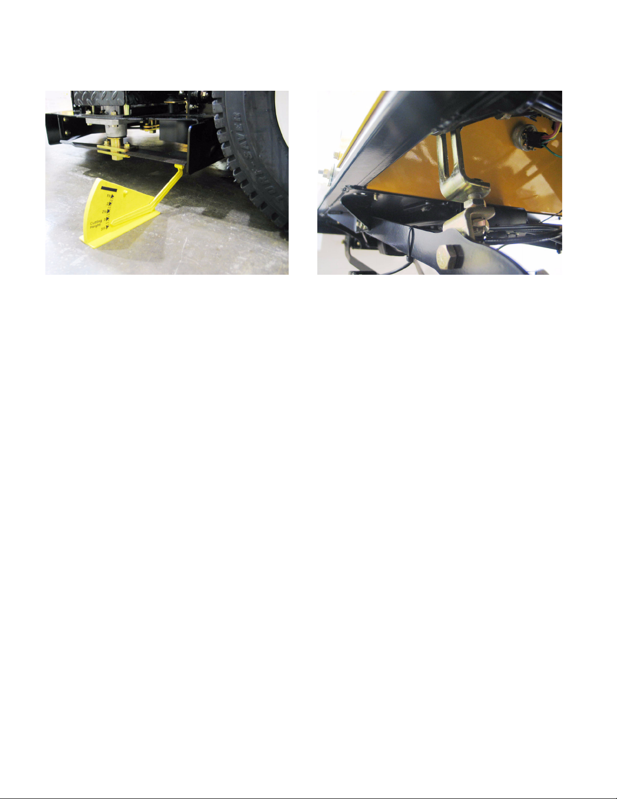
9.2. Side-to-side measurement: See Figure 9.2.
Figure 9.2 Figure 9.4
• Orient the outer pair of blades fore-and-aft.
• Check the vertical play on each element of the
blade assemblies to be measured. There will be
some up and down travel at the blade tips, generally between 1/8” and 1/4” (3.175mm and
6.35mm). If the amount of play significantly
exceeds this range, or is not consistent between
blade elements, identify the cause and correct it.
• Aerodynamic down-force overcomes the centrifugal force that keeps the blades perpendicular to
the spindle axis at mowing speeds: the blades
operate at the lower end of the available play.
• Measure the distance to the ground from the left
and right rear blade tips. It should be equal.
9.3. If the distance from the left and right rear blade
tips to the ground is equal, proceed to fore-andaft pitch measurement. If the distance is not
equal, level the deck as described under the
Side-to-side leveling sub-heading.
9.4. Side-to-side leveling: See Figure 9.4.
Adjustable link:
left-hand side
• The right side deck lift link is fixed in length,
while the left side link is adjustable.
• Loosen the jam nut that locks the adjustment on
the left lift link using a 3/4” wrench.
• Move the adjustment nut up or down as necessary to level the deck, using a 3/4” wrench.
• Tighten the jam nut, and double-check the level.
Readjust if necessary.
9.5. Fore-and-aft pitch measurement:
• Measure the distance to the ground from the
front and rear tips of the right side blade.
• The front blade tip should be between 1/8” and
1/4” (3.175mm and 6.35mm) closer to the
ground than the rear blade tip.
• This measurement should be the same for the
left side blade too. If it is not, identify and correct
the cause.
• If adjustment is necessary, proceed as
described in the deck pitch adjustment subheading.
14
Page 19

Cub Cadet Commercial Z-Wing
9.6. Deck pitch adjustment: Mowers produced
before November 2005.
Spherical rod end
Figure 9.6
• Loosen the jam nut that locks against the spherical rod-end connecting the front of the cutting
deck to the front lift arm assembly using a 15/16”
wrench.
See Figure 9.6.
Adjustment
bolt
Jam nut
• Loosen the jam nuts that lock against the front
rod lift tube using a 15/16” wrench.
• Tighten or loosen the pitch adjustment nuts as
required to achieve a nose-down blade attitude
(lower at the front of the blade than at the back)
of 1/8” to 1/4” (3.175mm and 6.35mm) using a
15/16” wrench.
• Tension on the adjusting nuts should be even.
If it is not, the looser side will amplify deck vibrations.
• Secure the adjustment by tightening the jam nut.
• The effect of adjustment is greater at lower cutting heights because the front deck lift arm is
closer to horizontal at higher cutting levels. It is
important to make this adjustment at the level
used most frequently by the operator.
9.9. Run and test the mower, inspecting cut quality,
before returning the mower to service.
9.10. Lateral brace adjustment: See Figure 9.10.
• Tighten or loosen the pitch adjustment bolt as
required to achieve a nose-down blade attitude
(lower at the front of the blade than at the back)
of 1/8” to 1/4” (3.175mm and 6.35mm) using a
15/16” wrench.
• Secure the adjustment by tightening the jam nut.
9.7. Run and test the mower, inspecting cut quality,
before returning the mower to service.
9.8. Deck pitch adjustment: Mowers produced after
November 2005, or retrofitted with a new deck
after November 2005:
U-shaped deck lift
bar has two adjustment points
See Figure 9.8.
Lateral
brace
Figure 9.10
• Mowers produced after mid-season 2005, but
before November of 2005 are equipped with a
lateral brace between the frame and the mowing
deck, similar to a panhard rod in the rear suspension of a car or truck.
• The lateral brace length should be adjusted so
that at the middle of the deck’s height travel it
exerts no force on the deck: if one of the mounting bolts is removed it will slip back-in without
force.
Figure 9.8
15
Page 20
Cub Cadet Commercial Z-Wing
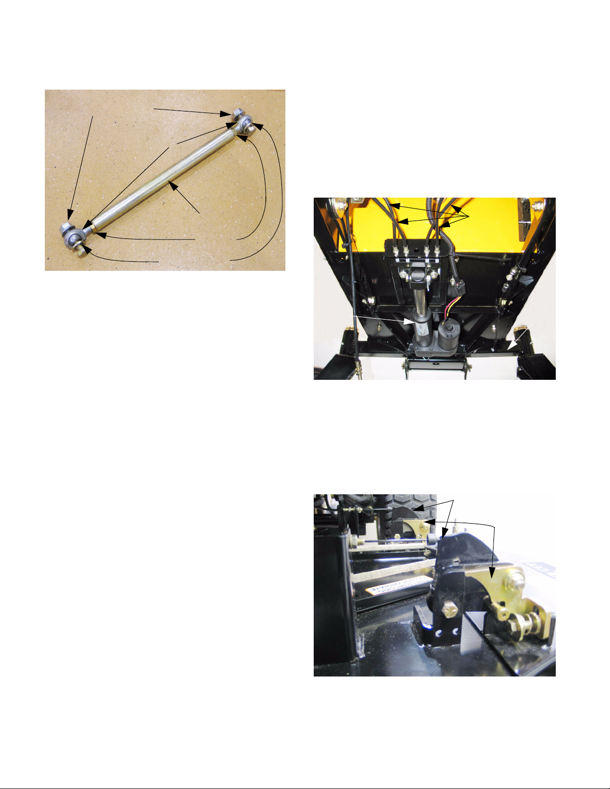
9.11. To adjust the lateral brace: See Figure 9.11.
Mounting nuts / bolts
Spherical rod ends
Center section
Jam nuts
Safety washers
Figure 9.11
NOTE: Safety washers prevent the lateral brace
from becoming disconnected if one of the spher
ical rod-ends fails.
• Loosen the jam nuts at each spherical rod-end
using an 11/16” wrench before disconnecting the
brace.
• Disconnect one end of the lateral brace, and
lengthen or shorten the brace as needed by
rotating the tubular center section.
• Both spherical rod ends are connected to the
center section with right-hand threads, so one
end must be disconnected for adjustment.
• Reconnect the end, and tighten the jam nuts.
• If the locking feature of the removed mounting
nut has worn, replace the nut or apply a small
amount of thread locking compound such as
Loctite 242 (blue).
10. DECK WING AND HINGE LOCK
NOTE: Mowers produced after mid-season 2005
use a different hinge lock mechanism than the
early 2005 production mowers. While the two
hinge locks are similar in operation, the actual
components differ substantially. The revised
hinge locks will be described in a sub-section
that follows the early hinge lock section.
10.1. How it works: See Figure 10.1.
Wing lift
cables
-
Linear
actuator
Figure 10.1
• A linear actuator mounted under the floor pulls
on a brace of cables. Each pair of two cables
unlatch and lift one deck wing.
10.2. Each deck wing has two hinge locks and lift
cable brackets, protected by lift wing shields.
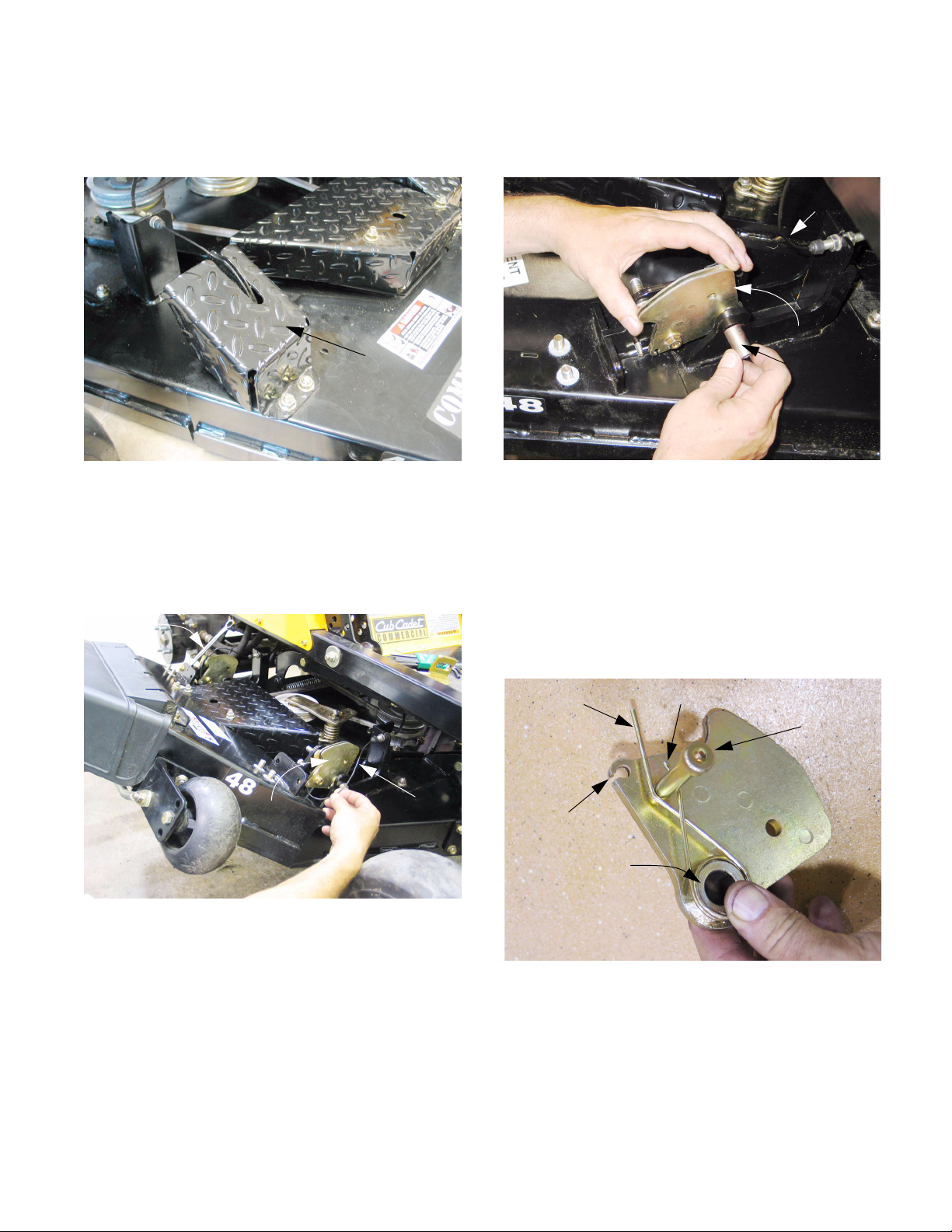
See Figure 10.2.
Lift cable brackets
Hinge locks
Pivot
bar
• Tighten the mounting bolt to a torque of 40 ft.lbs. (54.25 Nm).
Figure 10.2
16
Page 21
NOTE: All four sets of hinge locks and brackets
are identical: the parts are interchangeable leftto-right and front-to-rear.
10.3. When the wing lift is activated, all four cables,
hinge locks, and lift mechanisms should work in
unison:
See Figure 10.3.
Cable bracket
Hinge lock
Cub Cadet Commercial Z-Wing
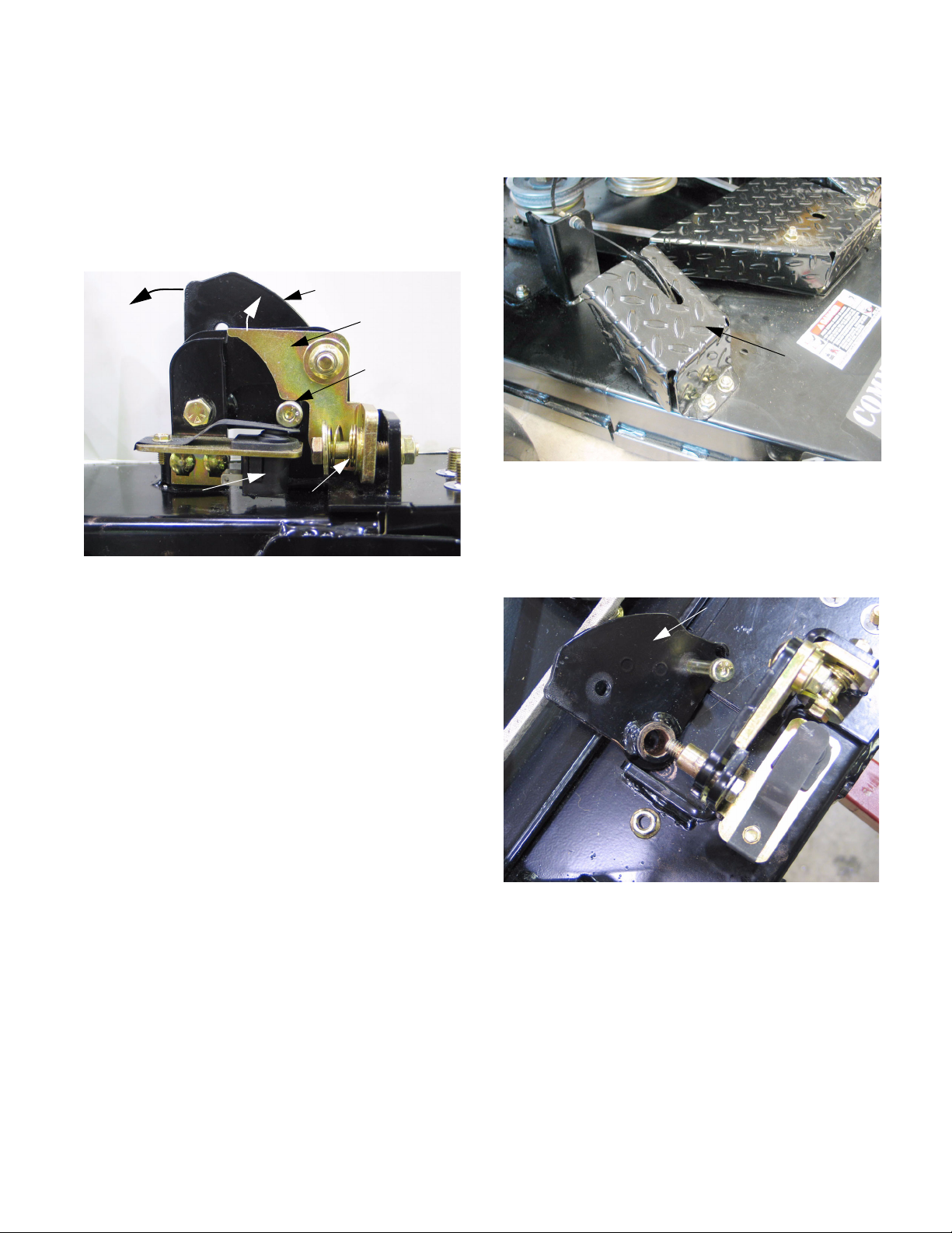
10.4. The lift mechanism can be reached by removing
the lift wing shield using a 9/16” wrench.
See Figure 10.4.
Socket-head
cap screw
Wing position switch Compression spring
Figure 10.3
• The force applied through the cable rotates the
cable bracket inward.
• The socket head cap screw attached to the
cable bracket moves upward, releasing the
plunger on the safety switch and rotating the
hinge lock clear of the corner of the deck hinge
• The force of a compression spring keeps the
hinge lock applied when the cable is slack.
• When the spring is compressed and the hinge
lock is clear of the hinge, the cable will begin to
lift the deck wing.
Lift wing shield
Figure 10.4
10.5. If the cable bracket is to be removed, it can be
unbolted with the cable attached using two 9/16”
wrenches. Once loose, the cable can be discon
nected from the bracket. See Figure 10.5.
Cable bracket
(unbolted)
-
• A clutch within the actuator prevents over-travel
when the wings reach the fully raised position.
• The safety switches prevent the operation of the
PTO with the deck wings raised.
• Proper adjustment is very important: refer to the
DECK WING CABLE ADJUSTMENT section of
this manual for the correct procedure.
• Proper hinge alignment is very important. If a
hinge becomes bent or damaged, it must be
repaired before the mower is used.
Figure 10.5
NOTE: The bolt and bushing that hold the
bracket are also the pivot point for the deck
wing.
17
Page 22
Cub Cadet Commercial Z-Wing
10.6. Orientation: on all four cable brackets, one side
of the bushing shoulder is thicker than the other.
The socket head cap screw always goes on the
side with the thicker shoulder.
Cable bracket Socket head cap screw
Figure 10.6
10.7. Assembly notes:
• Reverse the disassembly process to install the
cable bracket.
• Lubricate the pivot point with anti-seize compound.
• Apply a small amount of thread locking compound such as Loctite 242 (blue), or replace the
nut if the locking feature of the nut is in question.
Tighten the nut to a torque of 20-25 ft-lbs (27-34
Nm).
• Confirm correct operation and adjustment of the
wing lift mechanism and all associated safety
features before returning the mower to service.
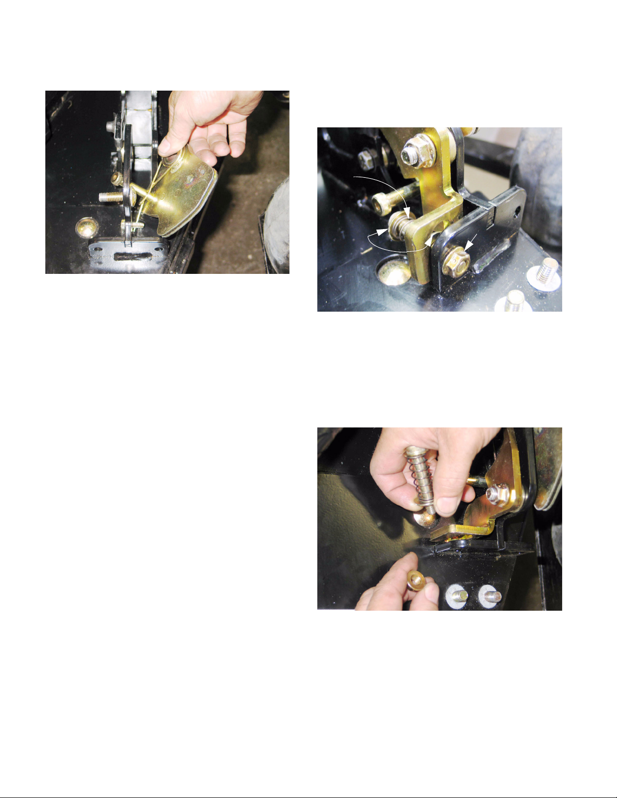
10.8. To remove the hinge lock, the compression
spring that holds the hinge lock against the
bracket on the deck wing must first be discon
nected.
See Figure 10.6.
-
10.10.Once the spring is released, remove the nut
from the carriage bolt that secures the hinge lock
and its shouldered bushing to the bracket on the
deck wing.
Carriage bolt (captive)
Shouldered bushing
Hinge
lock
Figure 10.10
10.11. The hinge lock assembly can then be removed
from the deck, except for the carriage bolt. The
cable bracket must be removed to release the
carriage bolt.
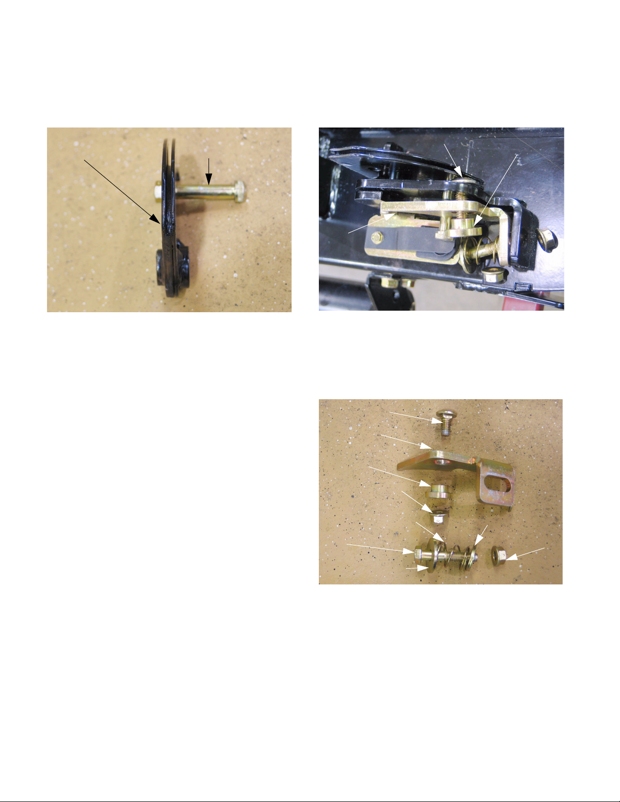
Carriage bolt
Hinge lock
Shouldered
bushing
Self locking nut
Compression spring Small flat washer
Bolt Self locking nut
Large flat washer
See Figure 10.11.
See Figure 10.10.
10.9. Remove the nut that secures bolt, flat washer,
and the compression spring using a pair of 9/16”
wrenches. The spring will still be captive, but it
can be removed when the hinge lock is unbolted
from the bracket on the deck wing.
Figure 10.11
18
Page 23
Cub Cadet Commercial Z-Wing
Hi
10.12.Assembly notes: See Figure 10.12.
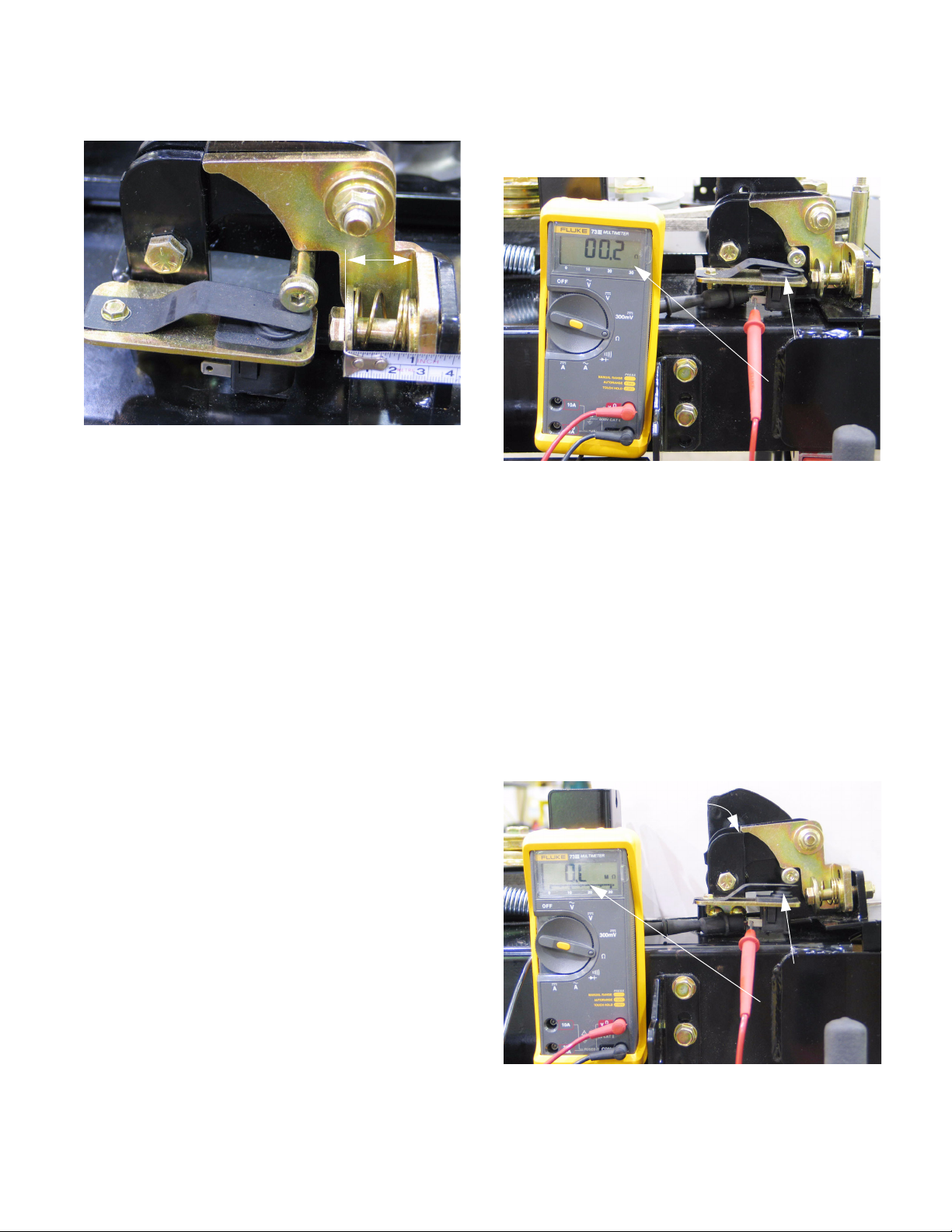
1”
Figure 10.12
• Reverse the disassembly process to install the
hinge lock.
• Lubricate the pivot point (shoulder bushing) with
anti-seize compound.
• Tighten the nut on the carriage bolt to a torque of
20-25 ft-lbs (27-34 Nm). Apply a small amount of
thread locking compound such as Loctite 242
(blue), or replace the nut if the locking feature of
the nut is in question.
• Tighten the nut that holds the compression
spring until the distance between the head of the
bolt and the near edge of the bracket on the
deck wing is 1” (2.54 cm), with the hinge lock
pressed firmly against the bracket. Apply a small
amount of thread locking compound such as
Loctite 242 (blue), or replace the nut if the locking feature of the nut is in question.
• Confirm correct operation and adjustment of the
wing lift mechanism and all associated safety
features before returning the mower to service.
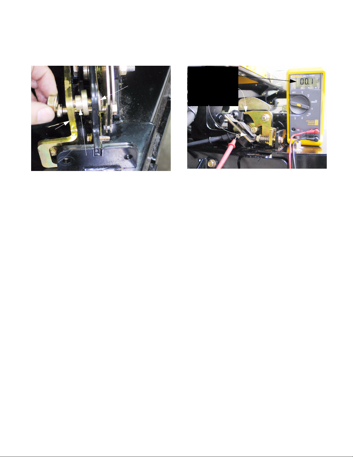
10.14.The switch contacts are normally open (N.O.),
meaning that the internal contacts are broken
when the plunger is extended.
Figure 10.14
• If the contacts fail to close when the plunger is
depressed, the PTO will not work.
• If the contacts fail to open when the plunger is
extended, an unsafe condition will exist.
• The switches should be tested whenever mower
deck maintenance is being performed.
10.15.The switches are mounted to a slotted bracket
using carriage bolts: they are adjustable.
10.16.The switches are correctly adjusted when the
contacts break just as the corner of the hinge
lock clears the corner of the hinge.
See Figure 10.16.
nge lock
just clears
corner of
hinge
See Figure 10.14.
Plunger down
Contacts closed
10.13.There is a safety switch mounted to the rear
hinge on each side of the deck.
• The switch is actuated by the socket head cap
screw that releases the hinge lock.
• If the switch contacts of both switches do not
close, the PTO will be disabled.
• Disabled PTO may be caused by a disconnected
switch, damaged wires, damaged switch, or a
misadjusted switch.
Plunger up
Contacts open
Figure 10.16
19
Page 24

Cub Cadet Commercial Z-Wing
11. HINGE LOCK: LATE 2005 PRODUCTION
11.1. When the wing lift is activated, all four cables,
hinge locks, and lift mechanisms should work in
unison:
Cable
J-nut
Torsion spring
Shouldered
cap screw
• The force applied through the cable rotates the
cable bracket inward.
See Figure 11.1.
Figure 11.1
Cable bracket
Hinge lock
NOTE:
new profile
Compression
spring
• There is a torsion spring connecting the hinge to
the cable bracket, giving the cable bracket more
positive return action.
• A J-nut has been positioned in a notch on the
hinge. The J-nut is hardened. This provides a
hard flat surface for the hinge lock to operate
against. The wear resistance of the J-nut will
provide more consistent locking action over
time, and is easily replaced.
• The compression spring that engages the hinge
lock is mounted on shouldered socket head cap
screw, eliminating the possibility of misadjustment.
11.3. The Safety switch that is mounted to each rear
hinge lock prevents the electric PTO from
engaging when the wings are not latched in the
down position.
See Figure 11.3.
• The socket head cap screw attached to the
cable bracket moves upward, releasing the
plunger on the safety switch and rotating the
hinge lock clear of the corner of the deck hinge
• The force of a compression spring keeps the
hinge lock applied when the cable is slack.
• When the spring is compressed and the hinge
lock is clear of the hinge, the cable will begin to
lift the deck wing.
• A clutch within the actuator prevents over-travel
when the wings reach the fully raised position.
• The safety switches prevent the operation of the
PTO with the deck wings raised.
• Proper adjustment is very important: refer to the
DECK WING CABLE ADJUSTMENT section of
this manual for the correct procedure.
• Proper hinge alignment is very important. If a
hinge becomes bent or damaged, it must be
repaired before the mower is used.
11.2. The revised hinge lock (2005/2) differs from the
original hinge lock (2005/1) in the following
ways:
Safety switch on
each rear hinge lock
Figure 11.3
• There is greater range of motion between the
point that the socket head cap screw releases
the plunger on the safety switch and the point
that it contacts the hinge lock.
20
Page 25
Cub Cadet Commercial Z-Wing
11.4. The lift mechanism can be reached by removing
the lift wing shield using a 9/16” wrench.
See Figure 11.4.
Lift wing shield
Figure 11.4
11.5. While the earlier cable brackets can simply be
unbolted with the cable attached, the torsion
spring on the revised cable brackets makes
them easier to remove if the cable is first discon
nected. See Figure 11.5.
11.6. The cable bracket can then be removed using
two 9/16” wrenches. Unbolt it and remove the
bushing.
Figure 11.6
11.7. The bolt and bushing that hold the bracket are
also the pivot point for the deck wing: If the deck
wing is to be completely removed, taking-off
-
both cable brackets will separate the deck wing
from the rest of the deck.
See Figure 11.6.
Cable
Cable bracket
Bushing
Wrench
Cable
bracket
Figure 11.5
• One hinge lock on the wing to be serviced can
be blocked open using an open-end wrench.
• The hinge lock nearest the cable bracket to be
removed can be manually unlatched.
• With both hinge locks released, the deck wing
can be lifted manually to slacken the cable.
• Slack in the cable allows the cable-end barrel to
be slipped out of the key-hole opening in the
cable bracket.
Cable
11.8. Orientation: on all four cable brackets, one side
of the bushing shoulder is thicker than the other.
See Figure 11.8.
Long arm Short arm
Key hole
opening
Shoulder that
surrounds the
bushing
Figure 11.8
• The socket head cap screw always goes on the
side with the thicker shoulder.
• The long arm of the torsion spring should be
nearer the cable bracket than the short arm.
• The long arm of the torsion spring fits under the
socket head cap screw.
Socket head
cap screw
21
Page 26
Cub Cadet Commercial Z-Wing
11.9. Assembly notes: See Figure 11.9.
Figure 11.9
• Reverse the disassembly process to install the
cable bracket: hook the long arm of the torsion
spring under the machine screw on the deck
wing hinge, and position the socket head cap
screw under the hinge lock.
• Lubricate the pivot point with anti-size compound.
• Insert the bushing, and secure the assembly
with nut and bolt.
11.10. To remove the hinge lock, the compression
spring that holds the hinge lock against the
bracket on the deck wing must first be discon
nected. See Figure 11.10.
Spring
Flat
washers
Figure 11.10
11.11. Remove the nut that secures bolt, flat washer,
and the compression spring using a pair of 9/16”
wrenches.
11.12. The shoulder bolt, spring, and flat washers can
all be removed if the spring is compressed with
finger pressure.
Nut
See Figure 11.12.
-
• Apply a small amount of thread locking compound such as Loctite 242 (blue), or replace the
nut if the locking feature of the nut is in question.
Tighten the nut to a torque of 20-25 ft-lbs (27-34
Nm).
• Confirm correct operation and adjustment of the
wing lift mechanism and all associated safety
features before returning the mower to service.
Figure 11.12
22
Page 27
Cub Cadet Commercial Z-Wing
11.13. The hinge lock and the bushing that it pivots on
can then be removed from the deck using a 9/
16” wrench.
Hinge lock
NOTE: The cable bracket must be removed to
release the carriage bolt.
11.14. Assembly notes:
• Reverse the disassembly process to install the
hinge lock.
• Lubricate the pivot point (shoulder bushing) with
anti-seize compound.
• Tighten the nut on the carriage bolt to a torque of
20-25 ft-lbs (27-34 Nm). Apply a small amount of
thread locking compound such as Loctite 242
(blue), or replace the nut if the locking feature of
the nut is in question.
• Tighten the nut that holds the compression
spring until the shoulder bottoms-out against the
bracket. Apply thread locking compound such as
Loctite 242 (blue), or replace the nut if the locking feature of the nut is in question. Tighten the
nut to a torque of 20-25 ft-lbs (27-34 Nm).
See Figure 11.13.
Carriage bolt
Bushing
Figure 11.13
11.16. The switch contacts are normally open (N.O.),
meaning that the internal contacts are broken
when the plunger is extended.
Contacts closed
Hinge lock latched
Plunger down
Figure 11.16
• If the contacts fail to close when the plunger is
depressed, the PTO will not work.
• If the contacts fail to open when the plunger is
extended, an unsafe condition will exist.
• The switches should be tested whenever mower
deck maintenance is being performed.
11.17. Each switch is mounted to a bracket that can be
rotated for adjustment:
• Loosen the switch bracket mounting bolt using a
pair of 9/16” wrenches.
• Rotate the switch bracket until the contacts open
and when the hinge lock is unlatched and close
when the hinge lock latches.
• Secure the bracket by tightening the bolt.
See Figure 11.16.
• Confirm correct operation and adjustment of the
wing lift mechanism and all associated safety
features before returning the mower to service.
11.15. There is a safety switch mounted to the rear
hinge on each side of the deck.
• The switch is actuated by the socket head cap
screw that releases the hinge lock.
• If the switch contacts of both switches do not
close, the PTO will be disabled.
23
Page 28

Cub Cadet Commercial Z-Wing
11.18. The switches are correctly adjusted when the
contacts break just as the corner of the hinge
lock clears the corner of the hinge.
See Figure 11.18.
Corner of hinge
Hinge lock
Figure 11.18
11.19. Test the operation of the switches after service is
complete, but before the lift wing shields are
reinstalled.
12.4. To remove the wing lift actuator, remove the cutting deck as described in the CUTTING DECK
REMOVAL section of this manual.
12.5. Retract the actuator:
• Insert the key in the key switch and turn it to ON.
• Work the rocker switch to lift the deck wings (disconnected), retracting the ram on the actuator.
• Turn the key switch OFF and remove the key.
• If the actuator has failed in the fully extended
position, or if the cable bracket is to be removed,
follow the steps described later in this section.
12.6. Disconnect the electric plug joining the actuator
to the rest of the harness.
Disconnect
See Figure 12.6.
12. DECK WING LIFT MECHANISM: EARLY 2005 PRODUCTION
NOTE: Decks having U-shaped front lift rods
were used on all Z-Wings produced after Nov. 1,
2005 (S/N: 0K015Z00001). These decks are ret
rofittable to earlier production. Earlier decks are
easily identified by V-shaped front lift rods that
connect to the deck at a single point.
12.1. Refer to the electrical section of this manual for
electrical diagnosis of the wing lift actuator.
12.2. The cable cores are all nylon jacketed, and
should have long service lives.
• Lubrication may be detrimental to the cables in
some operating conditions, adhering grit to the
cable or softening the cable core jacket.
• If any lubricant is applied, use a dry product like
graphite or dry Teflon (PTFE) such as Tri-flo
brand.
12.3. If one cable needs replacement, and it has not
suffered from some identifiable damage or
cause for accelerated wear, a good case can be
made for replacing all four cables.
Figure 12.6
-
12.7. Remove the hairpin clip and clevis pin and connecting the rear (ram) of the actuator to the
cable bracket.
Cable bracket
See Figure 12.7.
Clevis pin
Figure 12.7
Ram end of
actuator
24
Page 29

Cub Cadet Commercial Z-Wing
12.8. Disconnect the front of the actuator:
• Remove the hairpin clip from the clevis pin that
secures the front of the actuator to the frame of
the mower.
• Hold the actuator to keep it from rotating.
• Drive the clevis pin up, releasing the actuator.
12.9. Carefully slide the actuator toward the back of
the mower to release it from the front bracket,
and lower it to remove it.
Slide back
then down
Actuator
See Figure 12.9.
Installation notes, continued:
• Lubricate the pivot points (clevis pins) with antiseize compound.
• Confirm correct operation and adjustment of the
hinge lift mechanism and associated safety features before returning the mower to service.
12.11. If the actuator has failed in the fully extended
position, or if it is necessary to remove the cable
bracket, the following sequence of instructions
will be more useful.
12.12.To remove the wing lift actuator, remove the cutting deck as described in the CUTTING DECK
REMOVAL section of this manual.
12.13.Disconnect the electric plug joining the actuator
to the rest of the harness.
12.14.Remove the rear hairpin clip and clevis pin that
hold the actuator to the cable bracket assembly.
12.15.Remove the four nuts that secure the cable
bracket assembly to the frame of the mower
using a 1/2” wrench.
See Figure 12.15.
Figure 12.9
12.10.Installation notes: See Figure 12.10.
Flat ground on pin
Index mark
Figure 12.10
• Reverse the disassembly process to install the
actuator.
Nuts (securing cable bracket to frame)
Figure 12.15
• It is acceptable to grind a small flat on one side
of the head of the front clevis pin, perpendicular
to the bore for the hairpin clip, for ease of installation.
25
Page 30

Cub Cadet Commercial Z-Wing
12.16.If the nuts are loosened from their carriage bolts
in small increments and slight downward force is
applied to the bracket, the square bosses on the
carriage bolts will remain engaged to the frame.
Tape placed over the heads of the carriage bolts
will also help keep them in place.
See Figure 12.16.
Tape to temporarily secure carriage bolts
Figure 12.16
12.17.Cut any cable ties that secure the lift cables to
the mower.
12.18.Lower the cable bracket assembly slightly to
clear the bolts, draw it rearward to clear the actu
ator, and remove it. See Figure 12.18.
12.19.Disconnect the front of the actuator:
See Figure 12.19.
Removing clevis pin
Figure 12.19
• Remove the hairpin clip from the clevis pin that
secures the front of the actuator to the frame.
• Hold the actuator to keep it from rotating.
• Lift the clevis pin up, releasing the actuator.
12.20.Carefully slide the actuator toward the back of
the mower to release it from the front bracket,
and lower it to remove it.
-
12.21. If the cables need to be replaced, remove them
as described in the following steps:
Cable bracket assembly
Figure 12.18
NOTE: Cable replacement can be accomplished
without removing the cable bracket assembly.
12.22.Remove the jam nuts from the end of each cable
using a 7/16” wrench and a 3/8” wrench.
See Figure 12.22.
Jam nuts
Figure 12.22
26
Page 31

Cub Cadet Commercial Z-Wing
12.23.With the jam nuts removed, the threaded end of
the cable housings will pass through the keyhole shaped slots in the end to the cable
bracket.
12.24.With the cables free of the cable bracket, the
actuator mounting bracket can be rolled out the
end of the cable bracket.
Cable bracket
Actuator mounting bracket
Figure 12.24
See Figure 12.24.
12.26.While the cable bracket and actuator mounting
bracket are disassembled, inspect the rollers
and their mounting hardware.
Roller
Shoulder bolt
Figure 12.26
NOTE: To judge the amount of wear on the roll-
ers, the new measurements are as follows:
O.D.= .880”, I.D.= .375”, Thickness= .283”
(O.D.= 2.24cm, I.D.= .95cm, Thickness= .72cm)
See Figure 12.26.
Washers
(horizontal axis
rollers only)
12.25.To separate Z-fittings on the end of the cables
from the actuator mounting bracket, remove one
of the vertical-axis rollers, and loosen the sec
ond one using a 1/2” wrench and a 3/16” allen
wrench. This will allow the cable retainer to
pivot, releasing the Z-fittings from the actuator
mounting bracket.
See Figure 12.25.
Vertical axis rollers
Cable
Retainer
Figure 12.25
NOTE: The 4 horizontal-axis rollers can be
removed in similar fashion, but there is a washer
-
between each roller and the actuator bracket.
12.27.On mowers produced after November of 2005,
the cable bracket assembly was changed. The
bottom lip of the current brackets flares outward,
while the earlier ones are bent in.
See Figure 12.27.
Figure 12.27
27
Page 32

Cub Cadet Commercial Z-Wing
12.28.On the early design, the rollers of the actuator
mounting bracket rode in a channel formed by
the bottom lip of the cable mounting bracket,
supporting the lift actuator.
12.29.The rollers on actuator mounting brackets made
since November of 2005 only contact the top
surface of the cable mounting bracket.
See Figure 12.29.
Rollers not enclosed in channel
Figure 12.29
12.30.The lift actuator is supported by a separate
bracket.
See Figure 12.30.
12.31.Installation notes: See Figure 12.31.
Ground flat
Index mark
Figure 12.31
• It is acceptable to grind a small flat on one side
of the head of the front clevis pin, perpendicular
to the bore for the hairpin clip, for ease of installation.
12.32.Assembly notes, continued:
• Reverse the disassembly process to install the
cables, brackets, and actuator.
• Lubricate the pivot points (clevis pins) with antiseize compound.
Figure 12.30
NOTE: Removal of the actuator and the actuator
mounting bracket are much easier on the mow
ers produced after November of 2005.
• Test to confirm correct operation and adjustment
of the hinge lift mechanism and associated
safety features before returning the mower to
service.
-
28
Page 33

13. DECK WING LIFT CABLE ADJUSTMENT
Cub Cadet Commercial Z-Wing
NOTE: The bat wing feature of the Z-Wing
mower is a key element in the sales of the
mower. Safe and dependable operation of the
feature is crucial to customer satisfaction. Cor
rect adjustment of the cables is vitally important
to the safe and dependable operation of the bat
wing feature.
13.1. Lower the deck wings all the way.
13.2. Remove the shields that cover each wing lift
mechanism using a 9/16” wrench.
See Figure 13.2.
Nuts securing wing
lift shields
Bolts are
captive
NOTE: Whether the tightest cable is on the left
or right wing, front or rear hinge, does not matter.
-
NOTE: Usually an exposed thread length of 1/2”
to 5/8” (12.7mm - 15.9mm) is a good starting
point if a new cable has been installed.
13.4. Tighten the second cable on the same wing until
the hinge lock is at the same point of disengage
ment as the first, using a pair of 1/2” wrenches.
See Figure 13.4.
Jam nut
Adjusting nuts
-
Figure 13.2
13.3. Turn the key switch to the RUN position, and
“Blip” the wing lift switch until the tightest cable
moves the hinge lock it is connected to just far
enough to free that hinge.
See Figure 13.3.
Adjustment needed: rear
lock is further disengaged
than front hinge lock.
Figure 13.4
13.5. Lower the deck wings, then begin to raise them:
• Watch the movement of the hinge locks to confirm that they are working at the same time.
• If the hinge locks or hinges are binding in any
way, repair them before proceeding.
• Make any necessary adjustments if they are not.
13.6. Adjust the cables on the second wing so that the
hinge locks both move in unison with the hinge
locks on the first wing.
Figure 13.3
29
Page 34

Cub Cadet Commercial Z-Wing
13.7. Operate the wings through 20 complete raise/
lower cycles:
• Confirm smooth and consistent operation of the
deck wings.
• Confirm that all four hinge locks are locking and
unlocking in sync. Jerky operation of 1 wing may
indicate that 1 lock is unlocking later than the
others.
• Confirm that both deck wings are operating in
sync.
• Confirm that all four cables are secured in such
a way that they will not be damaged by normal
belt or linkage movement.
• Make any adjustments or repairs necessary to
achieve 20 trouble-free cycles.
• Tighten the jam nuts when testing is completed.
• Check the safety switches that are used to confirm that the wings are down. Make any repairs
or adjustments necessary for the correct operation of the safety switches, as described in the
DECK WING AND HINGE LOCK section of this
manual.
14. DECK LIFT MECHANISM
14.1. If the deck lift shaft, the hubs it rides in, or any
associated linkage need repair, the following
procedure will provide guidance in removal and
installation of those parts.
14.2. Begin by removing the cutting deck as described
in the CUTTING DECK REMOVAL section of
this manual.
14.3. Disconnect the front of each lift arm from the
mower frame using a 9/16” wrench and a 3/4”
wrench.
See Figure 14.3.
Lift arms
48” deck uses rear set of holes
Figure 14.3
NOTE: There are two sets of holes in the
bracket that the front of the lift arm mounts to.
They are correctly positioned in the rear set of
mounting holes.
NOTE: The lift links mount inboard of the lift
arms: the left side lift link is adjustable, the right
side lift link is fixed-length.
30
Page 35

Cub Cadet Commercial Z-Wing
14.4. The deck lift arms and their connection points to
the deck were modified in November of 2005.
The new arms feature a bushing at the connec
tion point to the cutting deck. See Figure 14.4.
Bushings
Figure 14.4
14.5. The bushings on both lift arms are off-set to the
left. The right side arm has a tab for the connec
tion of a lateral brace that was introduced at midseason, 2005. The lateral brace was disused in
November 2005.
See Figure 14.5.
14.7. Disconnect and remove each lift arm and lift link
assembly.
-
Lift arm
Lift link
14.8. Confirm that the deck height control is in the
highest (Transport Lock) position, minimizing
tension on the lift-assist springs. When raising
-
the deck lift handle, remove the clevis pin from
above it with caution because the handle will be
under tension from the lift-assist springs.
See Figure 14.8.
See Figure 14.7.
T-head
Figure 14.7
Connecting point
for lateral brace
Figure 14.5
14.6. With the front of each lift arm disconnected from
the frame, the lift links can be angled-back so
that the slot in the lift link fits through the T-head
weldment on the lift-shaft assembly.
Deck lift handle
Shoulder bolt
securing deck lift
handle in Transport
Lock position
Figure 14.8
31
Page 36
Cub Cadet Commercial Z-Wing
14.9. Remove the locking nuts from each bolt that
connects the lift assist springs to the bellcranks
on the lift shaft assembly using a 9/16” wrench.
14.10.Disconnect the springs from the bolts using a
length of recoil rope or an appropriate hook tool.
See Figure 14.10.
Lift assist spring
Recoil
starter rope
Figure 14.10
14.12.The bolts that hold the lift hub assemblies to the
control housing are accessible through openings
in the sides of the housing.
Bolts
holding lift hub assemblies
Figure 14.12
NOTE: Have a length of bungee cord capable of
maintaining light pressure across an 18” span
handy before removing the lift hub bolts.
See Figure 14.12.
14.11. Each end of the lift shaft assembly is carried by a
hub assembly.
See Figure 14.11.
Lift hub
assembly
Lift shaft assembly
Figure 14.11
14.13.Loosen, then remove the pair of bolts that
secures each lift hub to the control housing
using a 9/16” wrench.
14.14. Carefully maneuver the lift shaft assembly out of
the control housing, between the two frame
channels. As it clears the frame, attach the
shock cord between the two left hubs, holding
the lift shaft assembly together.
See Figure 14.14.
32
Figure 14.14
Page 37

Cub Cadet Commercial Z-Wing
14.15. Rotate the left end of the lift shaft rearward to
free the deck height control handle from the
index assembly, and remove the assembly to a
workbench.
14.16.Once on the bench, the bungee cord can be
removed.
See Figure 14.15.
Bungee cord
Figure 14.15
See Figure 14.16.
14.17.The left side hub will simply slip off of the shaft.
See Figure 14.17.
T-head
for lift link
Left lift hub
Figure 14.17
14.18.The right side hub will slip off of the shaft as well,
but it also retains the deck height control lever.
See Figure 14.18.
Lift handle
Carriage bolt
Lift shaft assembly
Deck lift handle
Lift shaft assembly
Lift hubs
Figure 14.16
Lift shaft assembly
Carriage bolt
Flat washers
Lift hub
Figure 14.18
33
Page 38

Cub Cadet Commercial Z-Wing
14.19.Assembly notes: See Figure 14.19.
Figure 14.19
• Apply anti-seize compound to the friction surfaces where the lift shaft assembly rides on the
lift hubs and the lift links.
• Use the shock cord technique to hold the
assembly together for installation.
• Tighten the bolt to a torque of 20-25 ft-lbs (27-34
Nm). Apply a small amount of thread locking
compound such as Loctite 242 (blue).
• A magnetic socket, or the gun patch technique
may be used to get the lift hub bolts started.
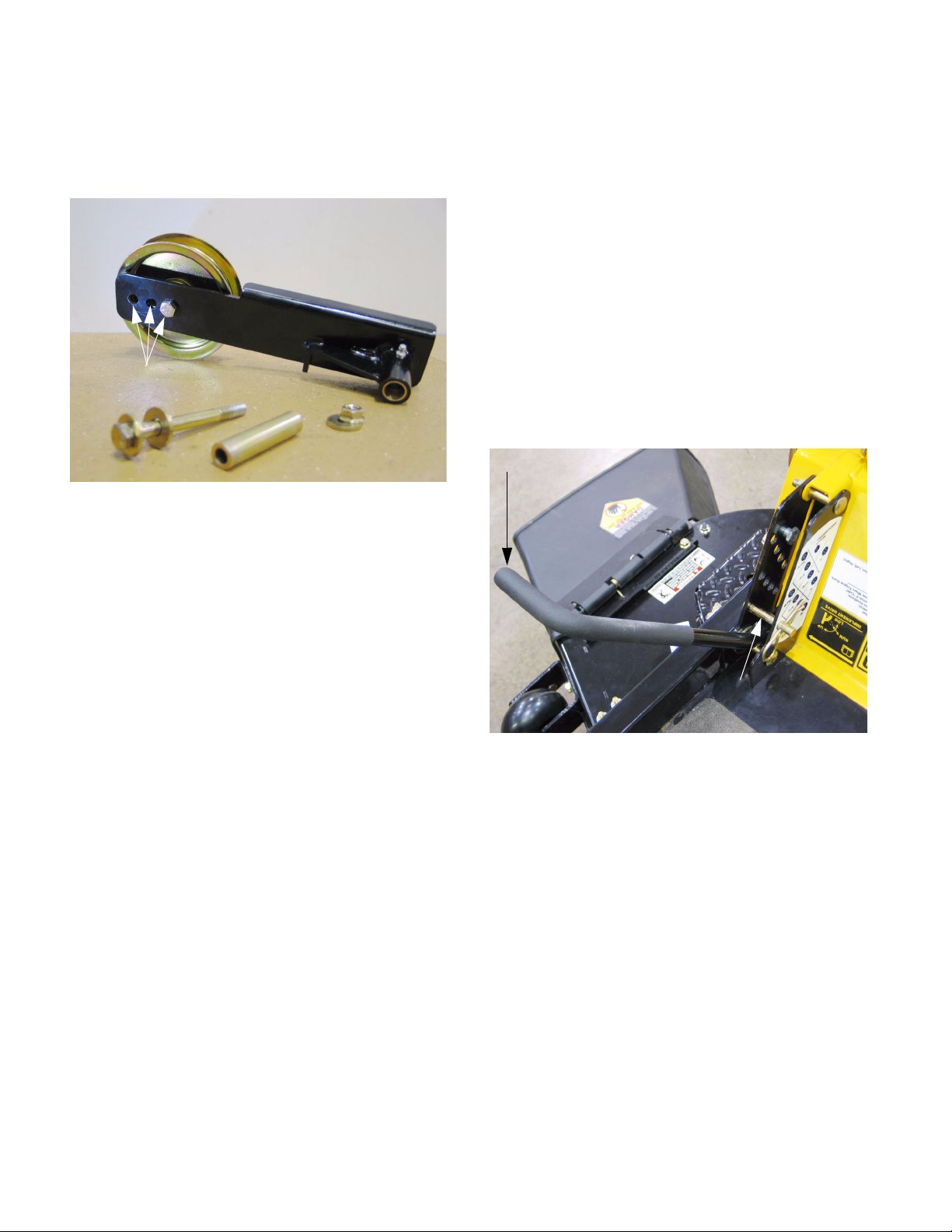
15. LAP BARS
15.1. The lap bars do not have room to pivot outward
in the conventional manner because they would
interfere with the deck wings in the raised posi
tion. For this reason, separate pivot handles
articulate on the lap bar pivot brackets which
fasten to the steering pivot plate.
See Figure 15.1.
Pivot handle
Figure 15.1
15.2. The pivot handles are bolted to the lap bar pivot
brackets, with washer on each side of the pivot
bar handle.
See Figure 15.2.
-
• Install the cutting deck as described in the CUTTING DECK REMOVAL section of this manual.
• If a lift hub should loosen, or the threads should
get stripped in the field, it is possible to reinforce
the installation with 3/8-16 nuts until a more permanent repair can be effected.
Washers
Figure 15.2
• The bolts should be tight enough to eliminate
play, but loose enough that they do not bind.
• Periodic tightening may be necessary using two
9/16” wrenches.
• Lubricate the joints weekly, per the Operator’s
Manual.
34
Page 39

Cub Cadet Commercial Z-Wing
L
t
15.3. The lap bar pivot brackets are adjustable to suit
individual operators.
Two Square
holes
Two slots
Tracking adjustment:
travel limiters
Steering pivot plate
neutral adjustment
• Carriage bolts in two square holes and two slots
provide adjustment for height and rake using a
single 1/2” wrench.
• A mechanical interlock with the parking brake
locks the steering pivot plates when the brake is
applied.
• High speed tracking adjustment is done by
adjusting rollers up or down on the steering pivot
plate to limit travel.
• The slotted connection between the steering
pivot plate and the hydrostatic pump control
allows “interlock neutral” to be aligned with true
neutral for the pump.
See Figure 15.3.
ap bar pivo
bracket
Steering
pivot plate
Brake interlock
Figure 15.3
16. CHECKING NEUTRAL ADJUSTMENT
CAUTION: Releasing the parking brake with the
engine at top no-load speed and loose or misadjusted control linkages can result in unpredict
able or uncontrolled movement of the mower.
• If the drive system makes a pronounced whining
sound, indicating that it may be severely out of
adjustment, do not release the parking brake.
• Perform the tests in a safe area that is free of
hazards, obstacles, other personnel, or pets.
• In cases where the misadjustment is pronounced, the tests may be performed at reduced
throttle settings, to help identify the nature and
location of the misadjustment.
16.1. With the engine warm and running at full throttle,
the hydro relief valves closed, and the parking
brake set: there should not be any abnormal
whining noise from the drive system.
16.2. With the engine warm and running at full throttle,
the hydro relief valves closed, and the parking
brake released: there should not be any ten
dency for either rear wheel to creep.
16.3. If either of these issues exist, neutral adjustment
is necessary.
16.4. The creeping action will provide clues about the
adjustment that is required:
• If both wheels tend to creep, both neutral settings may need to be adjusted.
• If only one wheel tends to creep, only that side
may need adjustment.
-
-
• The direction of the creepage will dictate the
direction of adjustment that is required.
16.5. Before adjusting the linkage, inspect it for any
bent, broken, stripped, worn, or loose compo
nents. This is particularly true if a mower that
was previously operating well has suddenly
35
gone out of adjustment.
-
Page 40

Cub Cadet Commercial Z-Wing
17. LINKAGE NEUTRAL ADJUSTMENT
17.1. Preliminary steps:
• Repair or replace any worn or damaged linkage
components before attempting to adjust the
steering linkage.
• Confirm that the parking brake interlock is working properly-repair it if it is not.
17.2. To isolate the problem to either the linkage or the
hydro pumps, loosen the nut and bolt that
secure the linkages to the steering pivot plates
using two 1/2” wrenches.
See Figure 17.2.
Steering
pivot plate
Slotted hole
Connection to
steering link rods
17.5. If the bolt that makes the connection between
the steering link rod and the steering pivot plate
is against the end of the slot in the plate, then
the steering link rod will need adjustment.
17.6. To reach the steering link rod adjustment point,
remove the hydro service plate:
Negative battery
Hydro service
plate
• Disconnect the cable from the negative terminal
on the battery using a 10 mm wrench.
cable and post
Figure 17.6
See Figure 17.6.
Figure 17.2
17.3. Repeat the test of neutral adjustment, as
described in the CHECKING NEUTRAL
ADJUSTMENT section of this manual.
• If the mower still creeps, or the drive system is
working against the brakes when it should be in
neutral, and the linkage is loose enough not to
interfere with the return to neutral action: the
adjustment must be made at the hydro.
• After adjustment at the hydro, the linkage is still
likely to need adjustment.
• If the mower does not creep, and the drive system is not working against the brakes (as indicated by a whining or groaning noise), then the
problem lies in the linkage.
17.4. If the problem lay in the connection between the
steering link rod and the steering pivot plate, the
simple act of loosening the connection and care
fully re-tightening it with the parking brake
applied should correct the adjustment.
• Remove the seven perimeter bolts from the
hydro service plate using a 7/16” wrench.
• Carefully lift the plate off of the mower.
17.7. Loosen both jam nuts that lock the adjustment
on the steering link rod using a 1/2” wrench
(nuts) and a 7/16” wrench to hold the spherical
rod end.
Spherical
-
rod end
See Figure 17.7.
Jam nut, hydro end
of steering link rod
Figure 17.7
36
Page 41

Cub Cadet Commercial Z-Wing
17.8. Loosen the bolt that joins the steering link rod to
the steering pivot plate using two 1/2” wrenches.
17.9. Engage the parking brake, locking the steering
pivot plate into the neutral position.
17.10.Lengthen or shorten the steering link rod as
required to center the bolt that connects it to the
steering pivot plate in the slot in the plate.
NOTE: The steering link rod has left-hand
threads at one end and right-hand threads on
the other. Its effective length may be increased
or decreased by rotating the rod.
17.11. Tighten all of the linkage hardware.
17.12.Replace the hydro service cover, and secure it
with two of the seven bolts.
17.13.Reconnect the negative battery cable.
17.14.Repeat the test of neutral adjustment, as
described in the CHECKING NEUTRAL
ADJUSTMENT section of this manual.
17.15.Test the operation of the mower and its safety
features in a safe area that is clear of hazards,
obstacles and bystanders before returning it to
service.
18. HYDRO NEUTRAL ADJUSTMENT
NOTE: The neutral adjustment on the hydro is
very rarely found to be out of adjustment.
18.1. Before proceeding with the adjustment make a
careful inspection of the return-to-neutral mech
anism on the hydro pump. See Figure 18.1.
NOTE: pump removed from
mower for photographic
clarity only
Return to neutral
“scissors”
mechanism
Return spring
Figure 18.1
• Disconnect the steering link rod as described in
the LINKAGE NEUTRAL ADJUSTMENT section
of this manual.
Steering linkage
connection point
Fixed arm:
sets the point
that the neutral
return comes
back to
-
• Check the mechanism for binding, interference,
or physical damage that might prevent it from
returning to neutral.
• Confirm that the extension spring that draws the
linkage back to neutral is present and undamaged.
18.2. After the return-to-neutral mechanism is confirmed to be operating correctly, adjustment is
the next step.
37
Page 42

Cub Cadet Commercial Z-Wing
18.3. The adjustment point is easily accessible
through an oval-shaped opening near the rear of
the control housing.
1/4” Allen
wrench
18.4. Loosen the socket-head cap screw that secures
the return-to-neutral mechanism using a 1/4”
allen wrench.
18.5. Confirm that no hazardous conditions will result
from starting the engine.
18.6. Lift and safely support the rear of the mower,
keeping the rear wheels off of the ground.
18.7. Connect the negative battery cable.
18.8. Start the engine, and operate it at a low throttle
setting. Do not release the parking brake.
18.9. Reaching in from the back of the control housing, carefully rotate the entire return-to-neutral
mechanism slightly forward or aft to find the
point where the drive system generates the least
amount of noise.
See Figure 18.3.
Figure 18.3
18.13.Connect the steering link rods and repeat the
adjustment described in the LINKAGE NEU
TRAL ADJUSTMENT, which will have shifted
slightly.
18.14.Disconnect the negative battery cable.
18.15.Install the hydro service plate.
18.16.Reconnect the battery.
18.17.Test the operation of the mower and its safety
features in a safe area that is clear of hazards,
obstacles, and other personnel before returning
it to service.
19. TRACKING ADJUSTMENT
19.1. After the neutral control is properly adjusted, its
appropriate to test the high speed tracking.
19.2. Loosen the rollers on the steering pivot plates
that act as travel stops, using a 9/16” wrench.
See Figure 19.2.
Steering
pivot plate
Travel stop
assembly
Spacers
(2 per)
-
18.10.After the adjustment is “roughed-in” at a low
throttle setting, increase the engine speed:
• The adjustment will be more sensitive at higher
engine speeds.
• Find the point where the least drive system
noise is created.
• Tighten the socket-head cap screw to secure the
adjustment.
18.11. Turn-off the engine.
18.12.Lower the rear wheels to the ground.
38
Washer Carriage
bolt
Figure 19.2
Jam nuts
(2 per)
Page 43

Cub Cadet Commercial Z-Wing
19.3. Make an initial adjustment of the travel stops on
each steering pivot plate:
• Push the lap bar forward gently to the limit of its
travel as set by the hydro control linkage.
• Push the forward travel stop down against the
top of the control housing, and tighten the nut
that secures that stop.
• Mark the position of the stops with a paint
marker or magic marker; any further adjustment
will be in the downward direction from these
marks.
• It is important that the travel stops on the steering pivot plate limit the movement of the steering
linkage, protecting the down-stream linkage from
excessive control in-put loads.
• Repeat this process in the rearward direction to
set the initial rear travel stop.
19.4. Make the following preliminary checks of factors
that may effect tracking:
• Rear tire pressure between 10-12 PSI (.690.828 bar.), and circumference equal to within 1/
4” (6.35mm) to keep the drive wheels equal in
size and firmness.
19.5. Test the operation of the mower in a safe area
that is clear of hazards, obstacles, and other
personnel:
• With both lap bars pushed fully forward, the
mower should travel in a straight line forward.
• With both lap bars pulled fully rearward, the
mower should travel in reverse in a straight line.
19.6. If adjustment is required, loosen the stop on the
steering pivot plate controlling the faster wheel
(opposite side from the direction of the veer).
Move the stop downward to equalize the speed
of the two drive wheels at full lap bar travel.
19.7. This procedure is similar for both forward and
reverse tracking.
NOTE: Variations in turf will effect tracking when
the mower is in use. These factors include trac
tion, soil firmness, grass depth, and grades. It is
up to the operator to compensate for these vari
ations using the mower’s controls.
19.8. If the mower does not respond to tracking
adjustments, test the pumps and motors as
described in the DRIVE SYSTEM section of this
manual.
-
-
• Front tire pressure between 20-25 PSI (1.38-
1.725 bar) to prevent drag that may pull the
mower off-track.
• Relief valves closed to prevent loss of hydraulic
pressure to either drive wheel.
• No hydraulic fluid leaks to prevent loss of
hydraulic pressure to either drive wheel.
• No brake drag to pull the mower off-track. Refer
to the BRAKE ADJUSTMENT section of this
manual for details.
• Hydraulic fluid reservoir full and up to operating
temperature.
• Pivot handles (lap bars) should be evenly
adjusted on their steering pivot plates to prevent
distorted perception of tracking issues.
• Steering linkages are functioning correctly, as
described in the LINKAGE NEUTRAL ADJUSTMENT and HYDRO NEUTRAL ADJUSTMENT
sections of this manual.
39
Page 44

Cub Cadet Commercial Z-Wing
20. STEERING PIVOT SHAFTS AND BUSHINGS
20.1. If the hex flange bushings that support the steering pivot plates become worn enough to effect
the precision of the steering, they are easily
replaced.
20.2. Set the parking brake.
20.3. Disconnect the battery cables (negative cable
first) using a 10mm wrench, and remove the bat
tery.
20.4. Disconnect the steering link rod using a pair of 1/
2” wrenches.
See Figure 20.4.
20.6. There are two hex flange bushings supporting
each steering pivot shaft. The outer-most can
simply be pried out of the control housing.
See Figure 20.6.
-
Outer hex flange bushing
Figure 20.6
20.7. The shaft, together with the inner hex flange
bushing can be withdrawn through the opening
normally occupied by the battery.
See Figure 20.7.
Figure 20.4
20.5. Unbolt the steering pivot plate from the steering
pivot shaft using a 9/16” wrench, and remove the
steering pivot plate.
Hex flange bushing
Steering pivot shaft
See Figure 20.5.
Connection to
steering link rod
Steering pivot
plate
Figure 20.5
Figure 20.7
40
Page 45

Cub Cadet Commercial Z-Wing
20.8. The steering pivot shaft.... See Figure 20.8.
E-clip flat washer Inner hex flange bushing
Flats for wrench
Figure 20.8
20.9. Installation notes:
• Apply lubricant to the friction surfaces of the
steering pivot shaft on assembly: In regions
where the mower will be in continuous duty, a
dry PTFE-based lubricant such as “Tri-flow dry
Teflon Lubricant” is appropriate. This will lubricate the pivot shaft without collecting abrasive
grit. In regions where there is an extended dormant period anti-seize compound will help keep
rust off the bearing surfaces during times of disuse.
• Apply a small amount of thread locking compound such as Loctite 242 (blue) to the threads
of the bolt that connects the steering pivot plate
to the steering pivot shaft. Tighten the bolt to a
torque of 35 ft-lbs (47.5 Nm).
• If the locking feature of the nut that secures the
steering link rod has worn, replace the nut, or
apply a small amount of thread locking compound such as Loctite 242 (blue) to the threads
of the bolt that connects the steering pivot plate
to the steering pivot shaft. Tighten the bolt to a
torque of 250 in-lbs (28.25 Nm).
20.10.Test the operation of the mower and its safety
features in a safe area that is clear of hazards,
obstacles, and other personnel before returning
it to service.
21. BRAKE LINKAGE ADJUSTMENT
21.1. Description: The brakes are cam-actuated shoe
brakes:
• Because they are cam actuated, if they are misadjusted in either direction, the brakes may drag,
or fail to hold the mower with sufficient force.
• The brakes are generously sized. Because they
are parking brakes, not service brakes, shoe
wear is not likely to be a significant factor unless
the brakes have been dragging.
• There is no internal brake adjustment such as a
star wheel: all adjustment is in the linkage.
• There is a mechanical interlock between the
brake linkage and the steering pivot plate. While
there is interplay between the interlock and
brake actuation, the interlock is covered in the
next section of this manual: BRAKE / PIVOT
PLATE INTERLOCK.
21.2. The basic premise of brake adjustment is that
the brakes should keep the mower from moving
when they are applied, and should not drag
when they are released. This is quite simple.
Brakes that drag can be referred to as too tight.
Brakes that fail to hold the mower with sufficient
force can be referred to as too loose.
21.3. Tight brakes are characterized by:
• The mower cannot be manually pushed (nor the
wheels rotated) with reasonable effort, with the
brake released and the relief valves open.
• The mower has persistent tracking issues, even
after the tracking adjustments have been correctly performed.
• The wheel motor on one or both sides of the
mower creates an unusual amount of noise and
heat. The noise may be a “chatter”, a “whine” or
a “groan”. The noise will be immediate, though it
may change with use. The temperature will go
up rapidly in the first 15 minutes of use.
• Heat will be generated not only by the friction of
the brake, but also by the increased loads on the
hydro pumps and wheel motors. The temperature of the fluid in the drive system will climb rapidly. High temperatures will significantly shorten
the service life of the pumps and motors. Damage or failure of these components that results
from continued operation with a dragging brake
is not warrantable. It is the customer’s responsibility to recognize when the performance of their
equipment degrades, and ensure that proper
repairs or maintenance are done.
41
Page 46

Cub Cadet Commercial Z-Wing
21.4. Characteristics of brakes that are too tight, continued:
• High effort required to pull up the lever that
applies the parking brake. Some “phantom”
resistance may be created by the over-center
action of the interlock linkage.
21.5. Brakes that are too loose are characterized by:
• Low effort required to pull up the lever that
applies the parking brake. Some “phantom”
resistance may be created by the over-center
action of the interlock linkage.
• The mower can be pushed (or the wheels
rotated) manually, with the relief valves open
and the brake applied.
21.6. Before making adjustments, make a visual
inspection of the brake linkage. Watch the link
a ge as i t is being oper a ted, and chec k for:
See Figure 21.6.
Steering
lock rod
21.7. Each brake adjustment nut can be reached
through an opening between the hydro service
plate and the control housing.
-
Figure 21.7
• There is one adjustment point for each side of
the mower.
• Adjustment can be made using a deep 9/16”
socket.
See Figure 21.7.
Output arm
Brake rod
Brake arm
Figure 21.6
• Loose, broken, or disconnected linkage components.
• Components that are binding because of corrosion, foreign objects, or misalignment (bent
links).
• Loss of travel because of worn bushings or hardware.
21.8. The brake rod is moved by an output arm
attached to the brake pivot shaft assembly.
There is a compression spring on each side of
the contact point. Tightening the nut puts more
pressure on those springs, loosening the nut
reduces the pressure on the springs.
See Figure 21.8.
Brake pivot
shaft assembly
Hydro
relief
valve
Brake rod
Figure 21.8
Output arm
Compression
spring
42
Page 47

Cub Cadet Commercial Z-Wing
21.9. Park the mower on a flat, firm, level surface, the
engine turned-off, and the hydro relief valves
open.
NOTE: If the mower has been run recently allow
the engine and drive system to cool long enough
to avoid burn injuries before beginning adjust
ment.
NOTE: Relief valves are located on the back of
each pump, immediately below the pivot brake
shaft.
NOTE: This test can also be performed with the
rear of the mower lifted and safely supported on
jack stands. In this case the wheels would sim
ply be rotated by hand rather than trying to push
the entire mower.
21.10.Release the parking brake.
21.11. Attempt to push (rotate) the right rear wheel of
the mower in either direction. There will be some
motor drag on the wheel, but it should rotate with
reasonable effort.
21.12.If the wheel will not rotate, or there is doubt as to
whether the brake is fully released or not, loosen
the adjustment nut until the wheel will rotate.
See Figure 21.12.
-
-
21.16.If the wheel does rotate, tighten the adjusting nut
in half-turn increments until the wheel is held
firmly.
21.17.Release the parking brake, and confirm that it
does not drag.
21.18.Repeat and adjust as necessary to assure correct brake operation.
21.19.Repeat the process on the left rear wheel.
21.20. When making brake adjustments, remember:
• There is about 1.5” (3.8cm) of thread length on
the end of the brake rod.
• The nut is roughly 1/2” (1.27cm) tall, including
the nylon locking ring.
• If 1” (2.54cm) of threaded rod is exposed above
the nut, the nut is bottomed-out, and out of
adjustment range.
21.21.If the nut bottoms-out or tops-out (the nylon locking ring reaches the end of the threads on the
brake rod) before correct adjustment is
achieved, the brake arm may be mis-indexed.
See Figure 21.21.
Brake adjustment nut
Compression
spring
(brake ON)
Steering lock rod
Figure 21.12
21.13.If loosening the nut does not allow the wheel to
rotate as it should, check the position of the arm
on the brake cam, as described later in this sec
tion of the manual.
21.14.Engage the parking brake.
21.15.Attempt to push (rotate) the right rear wheel of
the mower in either direction. It should not turn.
Output arm
Figure 21.21
NOTE: This is not a likely occurrence unless it
was improperly assembled, or someone unquali
fied to work on the brakes has tampered with it.
-
21.22.To reach the brake adjustment arm:
• Loosen the lug nuts using a 3/4” wrench.
• Lift, and safely support the back of the mower,
raising the rear wheels off the ground.
• Remove the rear wheels.
-
43
Page 48

Cub Cadet Commercial Z-Wing
21.23.Remove the hairpin clip that secures the brake
rod to the brake arm. The brake return springs
will center the brake arm.
Brake arm, to be adjusted
Figure 21.23
21.24.Some idea of which way the arm needs to move
can be obtained by comparing the position of the
arm (now centered in the “OFF” position) to the
end of the brake rod that engages the arm.
See Figure 21.23.
21.26.Carefully pry-off the clip that holds the brake arm
o nto t h e splined e n d of the brak e cam shaft .
See Figure 21.26.
Spring clip
Brake arm
Figure 21.26
21.27.Rotate the brake arm one spline in the direction
that needed to bring the adjustment nut back
into its operating range.
See Figure 21.27.
21.25.Match-mark the initial position of the arm to provide a point of reference. See Figure 21.25.
Figure 21.25
Figure 21.27
21.28.Re-connect the brake rod to the brake arm, and
adjust as necessary to make the brakes work
properly.
21.29. If further adjustments are needed to the arm
position, they can be made before the final nut
adjustments are made.
21.30.The final aspect of adjusting the brake linkage is
to make sure the interlock between the brake
and the steering pivot plates is working correctly.
44
Page 49

Cub Cadet Commercial Z-Wing
21.31.The interlock is actuated by two steering lock
rods; one for each steering pivot plate. The
steering lock rods extend forward from the out
put arms on each end of the brake pivot shaft.
See Figure 21.31.
Brake output arm
Steering lock rod
Figure 21.31
21.32.A post (consisting of a bolt, washers, and spacers) is attached to the other end of the steering
lock rod, guided by a slot in the control housing.
See Figure 21.32.
21.34.The post is easily loosened for adjustment, or
removal using a pair of 1/2” wrenches.
-
See Figure 21.34.
Nut
Steering
lock rod
Figure 21.34
21.35.A sleeve within a sleeve creates a shoulder
bushing. A steel washer rides on the shoulder to
support a nylon washer that rides outside of the
control housing. A second nylon washer rides
between the steering lock rod and the inside sur
face of the control housing. See Figure 21.35.
-
Steering pivot plate
Post
(steering lock)
Figure 21.32
21.33.When the brake is actuated, the posts slide forward to engage the notches in the rear edges of
the steering pivot plate. When the lap bars are
not in neutral, they also prevent the brakes from
being engaged while the mower is in motion.
Spacers (sleeves)
Nut Plastic washers Steel washer Bolt
Spacers (sleeves)
Figure 21.35
45
Page 50

Cub Cadet Commercial Z-Wing
21.36.The steering lock post is installed on the control
housing as illustrated below.
Plastic washer
Steel washer
Large sleeve
Small sleeve
Figure 21.36
21.37.Adjustment is made by loosening the post and
extending the steering lock rod to the limit of its
travel.
See Figure 21.37.
Brake handle pivot
See Figure 21.36.
21.38.When the linkage is in this fully extended position, push the post being adjusted as far as it will
go in the notch in the rear edge of the steering
pivot plate and tighten the nut.
Slide post into notch
Figure 21.38
21.39.Test the operation of the steering and brake controls, and all related safety features before
returning the mower to service. Tests should be
done in a clear area that is free of hazards,
obstructions, and other personnel.
See Figure 21.38.
Position
handle
here
Brake link rod
Figure 21.37
NOTE: Because of the cam-over effect that is
used lock the parking brake in whichever posi
tion it is set, the rod is at full extension at the
apex of the brake link rod’s travel. The brake link
rod will be centered over the head of the bolt that
the brake handle assembly pivots on.
-
22. BRAKE PIVOT SHAFT REMOVAL
NOTE: The brake pivot shaft itself is a 3/4”
(19mm) thick solid steel shaft. As such it is not
likely to require service. The bushings that sup
port the shaft, the input arm and the output arm
that transfer force through the shaft may require
service.
22.1. Park the mower on a flat, firm, level surface.
22.2. Lift and safely support the mower.
22.3. Remove the rear wheels using a 3/4” wrench.
22.4. Release the parking brake to remove any tension from the brake linkages.
22.5. Disconnect the top ends of the brake rods from
the arms on both ends of the brake pivot shaft
(input arm on the left end, output arm on the
right end) using a 1/2” wrench.
46
-
Page 51

Cub Cadet Commercial Z-Wing
22.6. Disconnect the bottom ends of the brake rods
from the arms on the brakes by removing the
hairpin clips.
Brake rod
NOTE: The brake rods must be moved out of the
way to gain wrench access to the socket head
cap screws that hold the input and output arms
to the brake pivot shaft. The brake rods may be
removed entirely, at the technician’s discretion.
22.7. If either of the arms (input or output) are to be
removed, disconnect the brake link rod and
steering lock rods using a pair of 1/2” wrenches.
See Figure 22.6.
Arm
Figure 22.6
22.10.From this point, the brake pivot shaft can be
driven far enough to achieve any necessary
repairs using a soft drift.
Brake pivot shaft
Output arm
Figure 22.10
NOTE: The shaft may be removed entirely if
necessary, or simply jockeyed back and forth to
service the arms an bushings.
22.11. The bushings can be easily driven inward for
removal. New bushings should be installed from
the inside-out.
See Figure 22.11.
See Figure 22.10.
Hex flange
bushing
22.8. Engage the parking brake to bring the nut up to
an angle that it can be reached with a wrench.
22.9. Remove the cap screws that connect the input
and output arms to the brake pivot shaft using a
1/2” wrench and a 1/4” allen wrench.
See Figure 22.9.
Figure 22.9
Figure 22.11
47
Page 52

Cub Cadet Commercial Z-Wing
22.12.Installation notes:
• Apply lubricant to the friction surfaces of the
steering pivot shaft on assembly: In regions
where the mower will be in continuous duty, a
dry PTFE-based lubricant such as “Tri-flow dry
Teflon Lubricant” is appropriate. This will lubricate the pivot shaft without collecting abrasive
grit. In regions where there is an extended dormant period anti-seize compound will help keep
rust off the bearing surfaces during times of disuse.
• If the locking feature of the nuts that secure the
steering lock rods or brake links has worn,
replace the nut, or apply a small amount of
thread locking compound such as Loctite 242
(blue) to the threads of the bolt that connects the
steering pivot plate to the steering pivot shaft.
Tighten the bolt to a torque of 250 in-lbs (28.25
Nm).
• If the locking feature of the nuts that secure the
input and output arms to the brake pivot shaft
has worn, replace the nut, or apply a small
amount of thread locking compound such as
Loctite 242 (blue) to the threads of the nut.
Tighten the nut to a torque of 250 in-lbs (28.25
Nm).
22.13.Test the operation of the steering and brake controls, and all related safety features before
returning the mower to service. Tests should be
done in a clear area that is free of hazards,
obstructions, and other personnel.
23. HYDRAULIC DRIVE SYSTEM: GENERAL OPERATION
23.1. System diagram: See Figure 23.1.
Front of mower
Filter
Reservoir
Return
Fill
Pick-up
A B A B
T T
Left Right
Pump Pump
S S
48
A B A B
Left Wheel Right Wheel
Motor Motor
Figure 23.1
Page 53

Cub Cadet Commercial Z-Wing
23.2. The hydraulic reservoir is accessible by tippingup the seat.
• Always clean the area surrounding the hydraulic
fluid fill-cap / dipstick before removing the cap.
Clean the area around any hydraulic fitting that
are to be disconnected including hoses and filter.
See Figure 23.2.
Figure 23.2
• The hose connected to the shorter tube at the
front of the tank is the return line.
• The hose connected to the longer tube at the
rear of the tank is the pick-up line, feeding the
hydrostatic pumps via the filter.
23.4. The hydraulic filter is mounted beneath a bracket
just in front of the reservoir. It is accessible for
service from below the frame.
Filter
See Figure 23.4.
• The reservoir contains 2 Qts. (1.89 L) of 5W40
synthetic hydraulic fluid (hydraulic drive system
fluid plus p/n: 737-3121), and the filter contains
roughly a pint (.47 L) of fluid. Total system
capacity is more.
• The fluid and filter should be changed after the
first 50 hrs. of operation, and after each 500 hrs.
of operation following the initial change.
23.3. Removing the hydro service plate using a 7/16”
wrench provides access to the reservoir and the
hoses that connect to it.
Pick-up tube:
line to filter
See Figure 23.3.
Return
fitting
Figure 23.4
23.5. The filter and housing are direction-specific. If
the hoses are disconnected for service, confirm
correct reattachment before operating the
mower.
“OUT”
See Figure 23.5.
To “S” port on From
each hydro. pump reservoir
“IN”
Figure 23.5
Figure 23.3
23.6. When changing hydraulic fluid, most of the reservoir will syphon out through the filter housing
once the filter is removed.
23.7. Disconnect the return lines at the T fitting near
the reservoir to drain them.
49
Page 54

Cub Cadet Commercial Z-Wing
23.8. The fluid will also drain out of the lines leading to
the pumps.
Relief
valve
23.9. The heavier hoses carry pressurized fluid
between the pumps and the wheel motors.
See Figure 23.9.
See Figure 23.8.
To other pump
To tank (reservoir)
“T”
“S”
From filter
Figure 23.8
“A”
To Wheel
motor
“B”
NOTE: cooling
fan removed
for visibility
23.10.The wheel motors are manufactured by White
Hydraulics. There is no financial nor managerial
relationship between White Hydraulics and
White Outdoor Power. They are a separate
company, and Cub Cadet Commercial is simply
a customer.
See Figure 23.10.
Figure 23.10
“B”
“A”
Figure 23.9
• The right side pump and wheel motor are
plumbed “A” to “B” and “B” to “A”.
• The left side pump and wheel motor are
plumbed “A” to “A” and “B” to “B”.
• This is necessary because two identical pumps
are driven in the same direction, but mounted in
a mirror-image relationship to one another. The
mounting reverses the direction of the control
inputs to one pump.
• White wheel motors feature a unique roller stator
design: The rollers reduce friction directly and
recover an oil film faster than a standard fixed
surface.
• For more information, visit:
//WWW.Whitehydraulics.com
• The model used here is of the CE Series.
24. HYDRAULIC DRIVE SYSTEM: DIAGNOSIS
24.1. The method used for testing the pumps is called
a “Flow Droop” test.
• The flow rate is tested at a pressure of 300 PSI,
and again at 1,100 PSI. The two flow rates are
compared to determine if the pump is damaged.
• If the pump is determined good, and there are no
external factors hurting the performance of the
drive system, then the motor can be determined
to be at fault through the process of elimination.
24.2. Before condemning (or even testing) a pump or
motor, a variety of external factors should be
checked. These include:
• Dragging brake
• Wrong fluid or filter
• Leak or fluid starvation
• Partially open relief valve
• Belt / tensioner issues
50
Page 55

Cub Cadet Commercial Z-Wing
24.3. If the performance of the right side drive system
is suspect, pay particular attention to the belt
and tensioner. There is more belt wrap on the
left pump pulley than the right because the ten
sioner is on the left side of the frame.
See Figure 24.3.
Belt
Te ns i on e r
spring
Te ns i on e r
pulley
Pulley, left side
hydro. pump
Figure 24.3
24.4. Observe normal hydraulic precautions:
-
24.6. Remove the wheels using a 3/4” wrench.
See Figure 24.6.
Figure 24.6
24.7. The gauge set should be connected so that the
fluid enters the gauge set from the pressure
gauge side and exits through the flow meter
side. There are a variety of way to accomplish
this. Bear in mind that:
• Allow the engine and drive system to cool before
disconnecting any fittings that may expose the
technician to hydraulic fluid.
• If the hydraulic system or gauge set develop any
leaks in the course of operation or testing: discontinue operation immediately, identify and
repair the leak.
• Relieve pressure from the system before disconnecting any components or fittings: with the
engine and brake off, stroke the controls through
their full range of motion.
• Clean the area surrounding any components or
fittings to be disconnected to prevent contamination of the hydraulic fluid.
• Clean-up any spilled fluid promptly to prevent
accidents.
• Wear eye protection while working on hydraulic
systems.
24.5. Lift and safely support the rear of the mower.
• Valid tests can be made in the forward or
reverse direction.
• Valid tests can be performed with or without the
wheel motor in the hydraulic circuit.
• Disconnecting just one hydraulic line from the
wheel motor, and installing the gauge set in
series with the motor is slightly less work than
disconnecting both lines
• Fluid flow: In forward motion, fluid enters the
wheel motor through the upper “B” port on the
motor and exits through the lower “A” port.
• Either port may be used:
The gauge set would be connected with the flow
meter nearest the wheel motor if the “B” port is
used and the test is made with forward wheel
motion.
The gauge set would be connected with the
pressure gauge nearest the wheel motor if the
“A” port is used and the test is made with forward wheel motion.
24.8. Configure the test kit for the intended installation, with fittings finger-tight to facilitate adjustment. Keep it within arm’s reach along with any
wrenches needed to tighten the fittings. Set-up
and wrench sizes may vary.
51
Page 56

Cub Cadet Commercial Z-Wing
24.9. Place a catch pan beneath the wheel motor connection to be removed, and loosen the hydraulic
hose using a 1” wrench and a 7/8” wrench.
See Figure 24.9.
“B” port
“A” port
Figure 24.9
24.10.Promptly install the gauge set to minimize fluid
loss.
See Figure 24.10.
24.15.Inspect the fluid for debris. Metal debris may
indicate that the wheel motor is worn. This
debris may enter the pump that is connected to
the motor, causing accelerated wear on the
pump.
• If the wheel motor is going bad, the pump may
be a victim part. It is still (arguably, more) important to test the pump to confirm it’s condition if
debris is found.
• If debris is found, the fluid and filter should be
replaced before the new components are
installed.
24.16.Confirm that the load valve on the test kit is fully
open, revealing all of the bands or marks below
the knob.
24.17.Top-up the hydraulic fluid to make up for any
fluid that was lost during gauge set installation.
See Figure 24.17.
Arrows
describe
flow
Gauge set
installed between
pump and motor
Figure 24.10
24.11. Position the gauge set so that it is visible and
accessible.
24.12.Start at the wheel motor end of the gauge set
connection and wrench-tighten each fitting.
24.13.If the “A” port was not chosen for the connection
point of the gauge set, briefly disconnect it using
a 1” wrench and a 7/8” wrench.
24.14.Catch a small quantity of fluid from the port fitting
on the wheel motor, then re-connect the line.
Figure 24.17
24.18.Confirm that no unsafe conditions will arise from
starting the engine or operating the drive sys
tem.
24.19.Place ballast on the seat to simulate an operator’s presence.
-
52
Page 57

Cub Cadet Commercial Z-Wing
24.20.Match-mark, then loosen the roller used to make
high-speed tracking adjustments using a 9/16”
wrench. Lift it up to allow full forward motion,
then snug-down the jam nut that locks the
adjustment.
24.21.Start the engine, release the brake, and work the
drive system:
See Figure 24.20.
Match marks
Figure 24.20
See Figure 24.21.
24.22.Begin the flow droop test with the throttle set to
3,400 RPM:
Valve:
open
• Gently pull the lap bar that controls the pump
being tested all the way forward, and hold it
there for the duration of the test.
• Observe the fluid flow rate. It should be near 9
GPM (34 LPM).
See Figure 24.22.
35 LPM
Pressure:
zero
Figure 24.22
Figure 24.21
• Purge any air from the hydraulic system.
•Check for leaks
• Bring the hydraulic fluid up to operating temperature: 168 - 210 f. (71 - 99 c.).
• Close the load valve until the pressure gauge
reads around 300 PSI (20.68 Bar.) Observe
the fluid flow rate. It should be near 7GPM (26.5
LPM). See Figure 24.22a
Flow:
27-28 LPM
Valve:
partially closed
Figure 24.22a
Pressure:
300 PSI
53
Page 58

Cub Cadet Commercial Z-Wing
24.23.After the 300 PSI (20.68 Bar) flow reading is
noted, close the load valve further, until the pres
sure gauge reaches 1,100 PSI (57.85 Bar). Note
the flow rate.
24.24. After noting the high pressure flow rate:
• Open the load valve to relieve the pressure.
• Return the lap bar to the neutral position.
• Throttle-down, then turn-off the engine.
24.25.Interpretation:
• If the difference in flow between the low pressure reading and the high pressure reading is
greater than 1.5 GPM (5.61 LPM), the pump has
a problem and should be replaced.
• If the difference in flow between the low pressure reading and the high pressure reading is
less than 1.5 GPM (5.61 LPM), the pump is
working properly.
See Figure 24.23.
Flow:
26-27 LPM
Valve:
nearly closed
Figure 24.23
Pressure:
1,100 PSI
25. HYDRAULIC DRIVE SYSTEM: PUMP
-
REMOVAL
25.1. The drive system employs a pair of Hydro-Gear
pumps:
• If a hydrostatic pump suffers a warrantable failure, it is to be replaced as a complete unit. The
dealer will be required to return the pump to Cub
Cadet for inspection and vendor recovery.
• Outside of warranty, the pumps can be feasibly
rebuilt for the customer or as an exchange unit.
25.2.Observe normal hydraulic precautions when servicing these pumps:
• Allow the engine and drive system to cool before
disconnecting any fittings that may expose the
technician to hydraulic fluid.
• If the hydraulic system or gauge set develop any
leaks in the course of operation or testing: discontinue operation immediately, identify and
repair the leak.
• Relieve pressure from the system before disconnecting any components or fittings: with the
engine and brake off, stroke the controls through
their full range of motion.
• Clean the area surrounding any components or
fittings to be disconnected to prevent contamination of the hydraulic fluid.
• Clean-up any spilled fluid to prevent accidents.
• Wear eye protection while servicing hydraulics.
25.3. After the engine cools sufficiently to safely work
near the muffler, relieve tension from the drive
belt and slip the belt off of the pulley driving the
pump to be removed.
See Figure 25.3.
• If the pump is working properly and other factors
have been eliminated, the wheel motor has a
problem and should be replaced.
Drive belt
tensioner
Pump
drive
pulley
Figure 25.3
54
Page 59

Cub Cadet Commercial Z-Wing
25.4. Remove the nut and flat washer that secure the
pulley to the input shaft that extends out the bot
tom of the pump using a 9/16” wrench.
See Figure 25.4.
Pulley
Flat washer
Nut
Figure 25.4
25.5. Install a small three-jaw puller to remove the pulley from the shaft. See Figure 25.5.
25.8. Remove the nut that secures the cooling fan
-
using a 9/16” wrench.
25.9. Lift-off the hub that the cooling fan rides on.
25.10.Disconnect the steering rod from the steering
input arm (part of the return-to-neutral mecha
nism) on the hydro. pump using a pair of 1/2”
wrenches.
See Figure 25.8.
Nut
Cooling
fan
Figure 25.8
-
Figure 25.5
NOTE: The shaft is keyed and tapered.
25.6. Tilt-up the seat and disconnect the cable from
the negative terminal on the battery.
25.7. Remove the hydro service plate using a 7/16”
wrench.
25.11. The hoses at the front of the hydro. pump connect the” “A” and “B” ports to the wheel motors.
Mark the hoses and disconnect them using a
pair of 7/8” wrenches.
Figure 25.11
NOTE: Letters identifying the ports on the hydro.
pump are embossed on the top of the pump
housing.
See Figure 25.11.
A and B lines:
marked
disconnected
plugged
25.12.Cap the fittings on the pump to prevent fluid spillage on removal, and plug the ends of the hoses
to prevent fluid contamination.
55
Page 60

Cub Cadet Commercial Z-Wing
25.13.Loosen the jam nut that secures the T-fitting to
the “S” port on the right side hydro. pump or the
L-fitting to the “S” port on the left side hydro.
pump, depending on which pump is to be
removed. Wrench size: 11/16”.
NOTE: This will allow the fitting to be rotated for
better wrench access.
25.14.Disconnect the supply hose(s) from the “S” port
on the pump using an 11/16” wrench.
NOTE: Because of the tight fit, it may be easier
to loosen the hose(s) from the “S” port to fingertight. After the pump is unbolted from the frame,
the pump may be maneuvered into a position
that allows easier removal of the hose(s).
25.15.Cap the fitting on the pump to prevent spillage
during removal, and plug the fittings on the
hose(s) to prevent contamination while disconnected.
25.16.Disconnect the return hose from the “T” port on
the hydro. pump using a screwdriver or 1/4” hex
driver to loosen the hose clamp.
See Figure 25.16.
-
25.18.Remove the nuts that secure the pump to the
frame using a 9/16” wrench.
Carriage bolts
(nuts
aboveabove
frame)
Figure 25.18
25.19.Disconnect the hose(s) from the “S” port, if not
already done, and lift the pump out of the mower.
25.20.On the bench: See Figure 25.20.
See Figure 25.18.
Return
hose
Figure 25.16
25.17.Cap the fitting on the pump to prevent spillage
during removal, and plug the hose to prevent
contamination while disconnected.
“T” port
Figure 25.20
• Drain any remaining fluid from the pump.
• Make a visual comparison to confirm that the
replacement pump is suitable.
• Transfer any necessary fittings or components to
the new pump.
• It may be necessary to loosen the lock nut that
holds the scissors arms on the new pump.
• Prime the new hydro. pump with fluid as well as
possible on the bench, and cap fittings.
• Open the relief valve.
56
Page 61

Cub Cadet Commercial Z-Wing
25.21.If there is a possibility of fluid contamination,
either as a cause of or a result of the pump (or
motor) failure:
• Replace the filter.
• Drain and properly dispose-of the remainder of
the fluid in the system.
• Remove and clean or replace the hoses connected to the “A” and “B” ports of the pump.
• Follow break-in procedure; initial fluid change
after 50 hrs. of operation.
NOTE: If hoses are cleaned with parts-washer
solvent, follow-up with hot soapy water and hot
water rinse. Dry thoroughly before reinstallation.
The parts washer solvent is an astringent that
will remove any traces of contaminated fluid.
The soapy water is a surfactant that will remove
any grit from the lining of the hose and flush
away any remnants of solvent. Residual solvent
will very effectively thin-out hydraulic drive sys
tem fluid.
25.22.Prior to installation, clean the area surrounding
the pump.
25.23.Affix the carriage bolts that hold the pump using
duct tape.
Square hole
for carriage bolt
See Figure 25.23.
-
25.25.Prime the “S” hoses that lead from the filter, if
they have lost substantial fluid.
See Figure 25.25.
Figure 25.25
25.26.Connect the hose(s) to the “S” fitting on the back
of the pump.
25.27.Install the nuts on the carriage bolts, and secure
the pump to the frame.
• If the locking feature of the nut has worn, replace
the nut, or apply a small amount of thread locking compound such as Loctite 242 (blue) to the
threads. Tighten the bolt to a torque of 35 ft-lbs
(47.46 Nm).
25.28.Connect the remaining hoses and steering linkage, then install the fan and drive pulley by
reversing the removal process.
Figure 25.23
25.24. Lower the pump into position over the carriage
bolts.
• Tighten the nut holding the pulley. If the locking
feature of the nut has worn, replace the nut, or
apply a small amount of thread locking compound such as Loctite 242 (blue) to the threads.
Tighten the bolt to a torque of 35 ft-lbs (47 Nm).
• Tighten the nut that secures the cooling fan. If
the locking feature of the nut has worn, replace
the nut, or apply a small amount of thread locking compound such as Loctite 242 (blue) to the
threads. Tighten the bolt to a torque of 140 in-lbs
(16 Nm).
• Tighten the nut that secures the steering rod. If
the locking feature of the nut has worn, replace
the nut, or apply a small amount of thread locking compound such as Loctite 242 (blue) to the
threads.
25.29.Re-fill the reservoir with Hydraulic Drive System
Fluid Plus.
57
Page 62

Cub Cadet Commercial Z-Wing
25.30.Re-connect the negative battery cable to the
negative terminal of the battery.
25.31.Confirm that no hazardous conditions will be created by running the engine or operating the drive
system.
25.32.Open the relief valve of the newly installed
pump.
25.33.Start the engine and purge the drive system:
• Lift and safely support the rear of the mower.
• Start the engine.
• Give the lap bar ten strokes over the full distance
of it’s travel, taking about 10 seconds to complete each stroke.
• Turn off the engine. Check the fluid level and
top-up if necessary. Check for leaks. Close the
relief valve.
• Start the engine.
• Give the lap bar ten strokes over the full distance
of it’s travel.
• Turn off the engine. Check the fluid level and
top-up if necessary. Check for leaks. Close the
relief valve.
26. HYDRAULIC DRIVE SYSTEM: WHEEL MOTOR REMOVAL
26.1. The wheel motors used in this application are
sourced from a company called White Hydrau
lics.
• Service parts are not available through Cub
Cadet.
• If a wheel motor fails within warranty or beyond
warranty, replace it as a complete unit.
• Within warranty you will be required to return the
wheel motor to Cub Cadet for inspection and
vendor recovery.
26.2. Observe normal hydraulic precautions:
• Allow the engine and drive system to cool before
disconnecting any fittings that may expose the
technician to hydraulic fluid.
• If the hydraulic system develops any leaks in the
course of operation or testing: discontinue operation immediately, identify and repair the leak.
• Relieve pressure from the system before disconnecting any components or fittings: with the
engine and brake off, stroke the controls through
their full range of motion.
-
• Lower the rear of the mower to the ground.
25.34. Install the hydro service plate.
25.35.Adjust tracking as necessary.
25.36.Test the operation of the mower and its safety
features in a safe area that is clear of hazards,
obstacles, and other personnel before returning
it to service. Some growling noise may come
from the drive system until all the air is purged.
• Clean the area surrounding any components or
fittings to be disconnected to prevent contamination of the hydraulic fluid.
• Clean-up any spilled fluid to prevent accidents.
• Wear eye protection while servicing hydraulic
systems.
26.3. Lift and safely support the Z-Force mower.
58
Page 63

Cub Cadet Commercial Z-Wing
26.4. Remove the wheel from the wheel motor to be
replaced using a 3/4” wrench.
Figure 26.4
26.5. Release the parking brake.
26.6. Disconnect the brake rod from the brake arm.
26.7. Match mark and disconnect the hydraulic hoses
from the wheel motor using a 7/8” wrench and a
1” wrench.
See Figure 26.7.
See Figure 26.4.
26.8. Unbolt the wheel motor from the frame using a 3/
8” allen wrench and a 3/4” wrench, and carefully
remove it.
Allen wrench
Figure 26.8
26.9. On the bench:
• Drain any remaining fluid from the motor.
• Make a visual comparison to confirm that the
replacement motor is suitable.
See Figure 26.8.
Inset: labeled hoses
Figure 26.7
• Catch escaping fluid in a drain pan.
• Check the fluid that comes out of the motor for
debris.
• Cap the fittings on the motor to prevent fluid
spillage on removal, and plug the ends of the
hoses to prevent fluid contamination.
• Transfer any necessary fittings or components to
the new motor.
26.10.If there is a possibility of fluid contamination,
either as a cause of or a result of the pump (or
motor) failure:
• Replace the filter.
• Drain and properly dispose-of the remainder of
the fluid in the system.
• Remove and clean or replace the hoses connected to the “A” and “B” ports of the pump.
• Follow break-in procedure; initial fluid change
after 50 hrs. of operation.
NOTE: If hoses are cleaned with parts-washer
solvent, follow-up with hot soapy water and hot
water rinse. Dry thoroughly before reinstallation.
The parts washer solvent is an astringent that
will remove any traces of contaminated fluid.
The soapy water is a surfactant that will remove
any grit from the lining of the hose and flush
away any remnants of solvent. Residual solvent
will very effectively thin-out hydraulic drive sys
tem fluid, contributing to performance problems
and premature component failure.
-
59
Page 64

Cub Cadet Commercial Z-Wing
26.11. Reverse the removal process to install the wheel
motor.
See Figure 26.11.
Wheel motor
removed
Figure 26.11
26.12.Access to the socket head cap screws around
the weights is tight. Once in position, a ball drive
allen wrench can be wedged against the weights
to ease installation.
See Figure 26.12.
26.13.Re-fill the reservoir with Hydraulic Drive System
Fluid Plus.
26.14.Confirm that no hazardous condition will be created by running the engine or operating the drive
system.
26.15.Open the relief valve of the pump that drives the
newly replaced wheel motor.
26.16.Start the engine and purge the drive system:
• Give the lap bar ten strokes over the full distance
of it’s travel, taking about 10 seconds to complete each stroke.
• Turn off the engine. Check the fluid level and
top-up if necessary. Check for leaks. Close the
relief valve.
• Start the engine.
• Give the lap bar ten strokes over the full distance
of it’s travel, taking about 10 seconds to complete each stroke.
• Turn off the engine. Check the fluid level and
top-up if necessary. Check for leaks. Close the
relief valve.
Ball drive Allen wrench
Figure 26.12
• If the locking feature of the nut has worn, replace
the nut, or apply a small amount of thread locking compound such as Loctite 242 (blue) to the
threads. Tighten the nut to a torque of 80 ft-lbs
(108.48 Nm).
• Tighten the lug nuts to a torque of 60 +
(68-95 Nm).
10 ft-lbs
• Lower the rear of the mower to the ground.
26.17.Adjust tracking as necessary.
26.18.Test the operation of the mower and its safety
features in a safe area that is clear of hazards,
obstacles, and other personnel before returning
it to service. Some growling noise may come
from the drive system until all the air is purged.
60
Page 65

Cub Cadet Commercial Z-Wing
27. FRONT AXLE AND CASTER WHEELS
27.1. The front wheels mount to the front caster
yokes.
See Figure 27.1.
Figure 27.1
• The wheels, bearings and tires are replaced as a
complete assembly when they are worn or damaged.
• The tires may be plugged or sealed in accordance with the instructions in the operator’s
manual.
27.3. The front wheels can be removed from the
yokes using a pair of 3/4” wrenches.
See Figure 27.3.
Zerk
Bearing cap
Valve stem
Spacer tube
Figure 27.3
• Lift and safely support the axle before removing
a wheel.
• Grease zerks and valve stems face outward for
easy access.
• The wheels each ride on two straight roller bearings.
• Front tires are inflated to between 20-25 psi
(1.38-1.72 Bar), with a maximum pressure of 28
psi (1.93 Bar).
27.2. Lubrication: Wheel bearings, caster yoke spindles, and the front axle pivot point are all to be
lubricated at weekly intervals using #2 Multipur
pose lithium-based grease, in accordance with
the Operator’s Manual.
• The roller bearings ride against a spacer tube.
• The caps the hold the bearings in place act as
thrust bearings within the yoke.
27.4. Installation: If the locking feature of the nut has
-
worn, replace the nut or apply a small amount of
thread locking compound such as Loctite 242
(blue) to the threads. Tighten the nut to 105 ft-lb
(142 Nm).
61
Page 66

Cub Cadet Commercial Z-Wing
27.5. The caster yokes each pivot on a pair of Timken
tapered roller bearings. They can be reached for
service by removing the grease cap that covers
each one.
Grease cap
Nut
27.6. Remove and discard the cotter pin that secures
the castle nut.
27.7. Remove the nut using a 1 1/8” wrench. It may be
necessary to brace the yoke using a 2X4 to pre
vent it from rotating.
27.8. There is a spacer above the top of the upper
bearing and below the bottom bearing.
27.9. The caster yoke can be pushed-out of the bearings with hand force or driven using a soft hammer or drift. See Figure 27.9.
See Figure 27.5.
Figure 27.5
27.10.The spacer at the bottom provides a surface for
the lip of the seal to ride against.
See Figure 27.10.
Seal
Spacer
Figure 27.10
27.11. The spacer is easily removed.
NOTE: The seal is only used at the bottom, the
top is taken care of by the grease cap.
-
27.12.The seal and lower bearing cone can be gently
pushed-out together using a soft drift.
See Figure 27.12.
Bearing races
Upper spacer
Upper
bearing
Figure 27.9
Lower spacer
Lower bearing cone
Seal
Figure 27.12
27.13.Bearing Service:
• Bearings may be cleaned, inspected, re-packed,
and reinstalled if they are undamaged.
• If bearing cones are replaced, the corresponding
races should be replaced as well.
• Keep bearings associated with the races that
they have been worn-into.
62
Page 67

Cub Cadet Commercial Z-Wing
27.14.Inspect the yoke shaft for wear. Repair or
replace it if the bearing cones have worn into the
shaft, or if the yoke exhibits other signs of wear
or damage.
27.15.To reinstall the yoke, after complete bearing
removal, use the following steps:
27.16.Drive the bearing races into place against the
lips on each end of the bore, using an appropri
ate drift or bearing driver.
27.17.Position the bottom bearing (cleaned, inspected,
and packed) in it’s race, and secure it by press
ing a new seal in behind it.
27.18.Drive the seal flush with the bottom edge of the
bore using a seal driver or a 2X4.
27.19.Lubricate the lip of the seal with grease or oil,
and position the lower spacer in the seal. If the
spacer has a wear ring on the sealing surface, it
may be reversed, or swapped with the upper
spacer.
See Figure 27.19.
-
-
27.25.Front axle removal can be done with the cutting
deck in-place, if the mower and deck are prop
erly supported.
27.26.Remove the grease caps and cotter pins from
each of the front caster yokes.
27.27.Loosen, but do not remove the castle nuts that
secure the caster yokes, using a 1 1/8” wrench.
27.28.Lift and safely support the mower by each side
of the frame, behind the front axle.
27.29.Support the cutting deck by the reinforced front
lip, just inside of each front deck gauge wheel.
This will take the weight off of the front lift rod.
See Figure 27.29.
Frame supported by
jack-stands
-
Seal
Lower spacer
Figure 27.19
27.20.Insert the yoke shaft up through the lower spacer
and bearing.
27.21.Install the cleaned, inspected and freshly packed
upper bearing over the shaft, followed by the
upper spacer and castle nut.
27.22.Support the yoke while tightening the castle nut.
27.23.Tighten the nut until all vertical play in the yoke
shaft has just been taken-up, then align the
nearest serration on the nut with the cross-bore
in the yoke shaft.
27.24.Secure the nut with a new 5/32” X 1 1/4” cotter
pin, and reinstall the grease cap.
Cutting deck supported by
jack-stands
Figure 27.29
27.30.Remove the caster yokes to make the front axle
easier to handle.
See Figure 27.30.
Front axle
without caster
yokes
Figure 27.30
63
Page 68

Cub Cadet Commercial Z-Wing
r
27.31.Remove the cotter pin that holds the front lift
support rod, and withdraw the rod.
See Figure 27.31.
Front lift support
rod removed
Front lift rod
disconnected
Figure 27.31
27.32.The front lift rod can then be unhooked from the
deck, and removed completely.
27.33.Remove the pivot bolt using a pair of 1 1/2”
wrenches.
See Figure 27.33.
27.34.Once the pivot bolt is removed, the front axle
bracket assembly may be taken-off using a 9/16”
wrench.
NOTE: The nuts are attached to carriage bolts
that are secured to the frame with speed nuts.
27.35.With the front axle bracket removed, the flat
washer and belleville washer at the front of the
pivot point will be exposed.
See Figure 27.34.
Figure 27.34
See Figure 27.35.
Front axle
bracket ass’y
Figure 27.33
Front axle bracket ass’y
Speed nut
secure
carriage bolts
Figure 27.35
NOTE: The flat washer has a smaller I.D., and
is sandwiched between the spacer tube and the
front axle bracket.
NOTE: The belleville washer has a larger I.D.
than the flat washer, and fits over the spacer
tube. The smaller contact patch (I.D.) faces the
flat washer, while the larger contact patch (O.D.)
faces the axle.
Flat washer
Belleville washe
64
Page 69

Cub Cadet Commercial Z-Wing
27.36.Lift the axle and spacer tube out of the frame.
See Figure 27.36.
Flat washer
Belleville
washer
Spacer tube
Figure 27.36
27.37.Behind the axle and tube is a second belleville
washer and flat washer, positioned in mirror
image to the ones in front of the axle. Behind
them is a self-locking retainer.
27.39.For easiest installation, the axle bracket, axle,
pivot bolt, spacer tube, and washers can be
lubed and pre-assembled, with the self-locking
retainer holding all the parts in place.
See Figure 27.39.
Washers
Pivot bolt
Axle bracket assembly
Axle
Pre-assembled,
ready for installation
Figure 27.39
27.40.Correct axle orientation:
27.38.Hardware orientation: See Figure 27.38.
Rear Front
Figure 27.38
• The grease zerk on the pivot point faces down,
and the longer boss on the axle tube goes to the
rear.
• The grease zerks for the caster yoke bearings
face rearward, and the tubes that the caster
yoke bearings fit in are of-set upwards from the
axle.
27.41.Install the nuts that secure the axle support
bracket. If the locking feature of the nuts has
worn, replace the nut or apply a small amount of
thread locking compound such as Loctite 242
(blue) to the threads and tighten them to a
torque of 35 ft-lbs (48 Nm).
27.42.Install the large locking nut that secures the pivot
bolt, and tighten it using a pair of 1 1/2”
wrenches. If the locking feature of the nut has
worn, replace the nut or apply a small amount of
thread locking compound such as Loctite 242
(blue) to the threads. Tighten the nut until all the
fore-aft play in the axle is taken-up, but not so
tight that friction inhibits the pivot action.
27.43.The remainder of the assembly process is to
reverse the steps of disassembly.
65
Page 70

Cub Cadet Commercial Z-Wing
28. ELECTRICAL: COMPONENTS
28.1. The key switch is easily removed from the front
panel of the control housing for diagnosis or
replacement.
• Disconnect the ground cable from the negative
battery terminal using a 5/16” wrench, or remove
the fuse to disable the circuit.
• Pry-off the rubber cover.
• Remove the retainer with a 3/4” wrench.
• Unplug the electrical connection, and withdraw
the key switch from within the control console.
28.2. The key switch has six spade terminals, five of
which are used in this application.
See Figure 28.2.
See Figure 28.1.
Cover
Retainer
D-shaped
hole and
collar
Figure 28.1
28.3. The key switch internal contacts are as follows:
See Figure 28.3.
B: Battery
S: Starter
M: Magneto
L: Lights
G: Ground
Figure 28.3
• OFF position: M+G+L
• RUN position: B+L
• Start position: B+S+L
28.4. The PTO switch is easily removed from the
front surface of the control housing.
See Figure 28.4.
Hour meter
/ tachometer
Vacant
PTO switch
Hour meter
/tachometer
Key switch
Figure 28.2
NOTE: Each spade is lettered on the inside-fac-
ing flat: M, L, B, G, S.
Figure 28.4
• The tabs may be reached from beneath the
frame, or by removing the battery.
• Squeeze the tabs to release the switch body
from the control housing.
• Unplug the electrical connector after pulling the
switch out of the control housing.
66
Page 71

Cub Cadet Commercial Z-Wing
28.5. The PTO switch has three sets of contacts:
A, B, & C.
A B C
Figure 28.5
• For each set of contacts, there are three male
spade terminals:
Comm on : (COM )
Normally Open: (N.O.)
Normally Closed: (N.C.)
• When the PTO switch is pushed-in (turned-off),
each COM spade is internally connected to the
N.C. spade (A, B, or C) that corresponds to it.
• When the PTO switch is pulled-out (turned-on),
each COM spade is internally connected to the
N.O. spade (A, B, or C) that corresponds to it.
See Figure 28.5.
NC
NO
COM
28.7. The PTO relay works as follows:
See Figure 28.7.
#87
Battery power
#88
winding +
Figure 28.7
• When power (blue wire, spade #88) and ground
(green wires, spade #85) are present, the windings in the relay are energized.
• When the relay is energized, battery power (red
wires, spade #87) is connected to the PTO
clutch (via red wire w/black trace, spade #30).
28.8. PTO clutch: The PTO clutch is an Ogura model
JD08 with brake (BBC).
See Figure 28.8.
#87A
#85
Winding -
#30
To PTO
clutch
28.6. PTO relay: The PTO relay can be found on the
main harness conduit, near the left front corner
of the engine.
PTO Relay
See Figure 28.6.
Engine oil
dipstick
Figure 28.6
PTO clutch
Figure 28.8
• Typical resistance in the clutch windings is 2.9 Ω.
A much higher reading indicates open windings.
• A new clutch should be burnished in accordance
with the Operators Manual.
• Air gap is adjustable. It should be .020”-.035”
(.51mm-.90mm), checked at 100-hr. intervals.
67
Page 72

Cub Cadet Commercial Z-Wing
28.9. Brake safety switch: The brake safety switch is
mounted in the control console, immediately
behind the parking brake lever.
Figure 28.9
28.10.The switch is most easily reached for service by
removing the two screws holding the switch
bracket to the control housing using a 5/16”
wrench. Once disconnected, the bracket and
switch can be lowered beneath the frame for
access, then unplugged.
See Figure 28.9.
Brake safety
switch
See Figure 28.10.
28.12.Seat safety switch: See Figure 28.12.
Seat safety switch
Seat safety switch plug
(defaults to closed circuit
when unplugged)
Figure 28.12
• The switch is enclosed in a housing that
attaches into the bottom of the seat with two
screws. They can be removed using a 3/8”
wrench.
• The contacts in the switch are normally closed
(N.C.).
• The switch is part of the engine kill safety circuit.
Figure 28.10
28.11. The brake switch contains two sets of contacts:
• One set is normally open, breaking the starter
circuit when the brake is not applied (switch
plunger up).
• One set is normally closed, as indicated by the
letters “N.C.” stamped on the spades. The N.C.
contacts are part of the engine kill safety circuit.
• The plug that connects to the switch contains a
contact that closes the circuit if the switch is
unplugged, defaulting to a closed circuit rather
than an open circuit.
28.13.Wing lift safety switch: The wing lift safety
switches are normally open (N.O.), and wired
together in series.
Wing lift
safety switch
See Figure 28.13.
Figure 28.13
68
Page 73

Cub Cadet Commercial Z-Wing
28.14.The contacts in the switches are closed when
the plungers are depressed by lowering the
wings.
• For adjustment procedures, refer to sub-sections
11.15 through 11.17 in the HINGE LOCK: LATE
2005 PRODUCTION section of this manual, or
sub-sections 9.15 and 9.16 in the DECK WING
AND HINGE LOCK section of this manual. Use
whichever instructions that apply to the mower
being serviced.
• Remove the lift wing shield using a 9/16” wrench
to gain access to the switch.
28.15.Wing lift control switch: To remove the switch:
See Figure 28.15.
Wing lift control switch
28.16.There are six spade terminals on the back of the
deck wing lift control switch, oriented in two col
umns of three: See Figure 28.16.
1
2
4
5
6
8
Figure 28.16
• Spades in one column are numbered: 1, 2, & 4.
• Spades in the second column are numbered: 5,
6, & 8.
-
Figure 28.15
• Remove the hydro service plate using a 3/8”
wrench.
• Reach forward in the left side of the control
housing to disconnect and remove the wing lift
control switch.
• The center spade in each column (#2 and #6)
are common, with #2 (red / black trace) carrying
power and #6 (black) carrying ground.
28.17.Rocking the switch in one direction closes contacts joining #1 to #2 (yellow) and #5 to # 6 (red),
connecting power to terminal #2 and ground to
terminal #5.
DOWN UP
1 5
2 6
4 8
See Figure 28.17.
Figure 28.17
1 5
2 6
4 8
28.18.Rocking the switch in the opposite direction
closes contacts joining #2 to #4 (red) and #6 to
#8 (yellow), connecting power to terminal #4 and
ground to terminal #8.
69
Page 74

Cub Cadet Commercial Z-Wing
28.19.Jumper wires connect... : See Figure 28.19.
Red jumper
Yellow jumper
Figure 28.19
• Terminal #5 to terminal #4 (yellow jumper)
• Terminal #8 to terminal #1 (red jumper)
• Effectively reversing polarity in the two wires that
lead to the wing lift actuator when the rocker
switch is in the DOWN position.
28.20.Wing lift actuator: The wing lift actuator
responds to the wing lift control switch, con
nected to it by the red (R) and yellow (Y) wires.
See Figure 28.20.
-
28.21.Fuse: The fuse holder can be found on the main
harness conduit, near the left front corner of the
engine. It should contain a 20A automotive type
fuse.
Fuse holder
28.22.There is a second fuse holder and fuse in the
harness, to the rear of the starter motor. This
fuse is used for other applications of the engine,
and is not of any importance in this electrical
system.
See Figure 28.21.
Figure 28.21
See Figure 28.22.
Yellow wire:
- to extend
+ to retract
Figure 28.20
• Positive current on the red wire, with ground on
the yellow wire causes the actuator to extend,
lowering the wings.
• Positive current on the yellow wire, with ground
on the red wire causes the actuator to retract,
raising the wings.
Red wire:
+ to extend
- to retract
Fuse holder:
Not used
Figure 28.22
70
Page 75

Cub Cadet Commercial Z-Wing
28.23.Battery: The battery is type 12CE18, which fits
tightly in a cavity beneath the seat.
See Figure 28.23.
Heavy gauge red
cable: to hot lug
on starter solenoid
14 gauge red wire: to B terminal
on key switch, via fuse holder
Figure 28.23
• It measures 7” wide x 3” deep x 6.5” tall (17.8cm
x 7.6cm x 16.5cm), and has an 18 A/Hr. capacity.
• The posts are oriented + left and - right when
viewed from the rear of the mower.
28.24.Hour meter: The hour meter is clipped-into the
front surface of the control housing. It can be
removed by unplugging the electrical connection
and squeezing the clips that secure it.
See Figure 28.24.
Heavy gauge black
cable: to ground
28.25.The hour meter incorporates an engine tachometer. See Figure 28.25.
Figure 28.25
• The hour meter is completely isolated from the
rest of the mower’s electrical system. It is driven
by an inductive signal from the spark plug wire.
• The function switches automatically to tachometer when the meter is receiving a signal from the
inductive pick-up, which happens when the
engine is running.
• When the signal ceases (engine is turned off),
the tachometer reverts to an hour meter.
28.26.Engine harness to mower harness connector: is
located near the starter motor.
See Figure 28.26.
Inductive
lead from
spark plug
Figure 28.24
Hour meter / tach.
Engine harness
Mower harness
Figure 28.26
71
Page 76

Cub Cadet Commercial Z-Wing
28.27.The harnesses are joined in the order indicated
in the chart:
See Figure 28.27.
Mower Harness Engine Harness
Circuit Color Color Circuit
Starter O/w Bu+R (2) Starter
Ground Gn Y (2X) Ground
Key Sw. M Y W (2X) Mag Kill
and Safety
Key Sw. L R R After-fire Sol.
Dead end R Fused hot
Bat. Cable R V Charge*
* Connects at hot lug on starter
Figure 28.27
28.28.Engine harness - magneto: The white wires
connect to the kill tang on each of the two igni
tion modules.
28.29.Engine harness - after-fire solenoid: The red
wire connects the after-fire solenoid on the bot
tom of the carburetor. See Figure 28.29.
Bullet
connector
-
28.30.Engine harness - alternator: Raw output from
the stator enters the regulator / rectifier through
two white wires, just visible under the flywheel.
28.31.Engine harness - regulator / rectifier: The regu-
lator / rectifier is mounted near the right front corner of the engine, extending into the blower
shroud.
Regulator / rectifier
Violet wire:
output
White wires
A.C. from stator
-
• The violet wire carries charging current to the
battery, via the hot lug on the starter.
• The L-shaped strap must maintain good ground
contact with the engine block.
See Figure 28.31.
Grounding
strap
Figure 28.31
After-fire solenoid
Figure 28.29
• Raw stator output enters through white wires.
28.32.The amperage out-put of the alternator can be
tested using an automotive VAT tester, a
Briggs& Stratton DC shunt (P/N 19359), or a
suitable amp meter.
• D.C. output should be 12.5 - 14.5 volts at 3,600
RPM with a fully charged battery.
72
Page 77

Cub Cadet Commercial Z-Wing
28.33.Engine harness - starter solenoid and starter:
The starter solenoid is attached to the starter
motor.
See Figure 28.33.
Starter
solenoid
Trigger wire:
Blue
Unused fused line:
Heavy gauge red cable
to + battery terminal
Figure 28.33
• The blue wire triggers the solenoid.
• The violet wire carries charging current from the
regulator / rectifier.
• The heavy gauge red cable carries battery current to the starter and carries charging current to
the battery while the engine is running.
• The smaller gauge red wire is not used in this
application.
Red 12 ga.
Charging
system
out-put:
Violet
29. ELECTRICAL: STARTER CIRCUIT
29.1. With the key in the START position, terminals B,
S, and L are connected within the switch.
See Figure 29.1.
M B
L G
A-F
Sol.
29.2. Terminal B is connected to the positive post of
the battery through a light gauge wire (red with
black trace) carrying a 20A in-line fuse.
29.3. The S terminal transfers battery power from the
B terminal to an orange wire with white trace (O/
w) when the key is in the START position.
29.4. The orange wire w/white trace leads to the common spade on the A set of contacts (A-COM)
within the PTO switch.
S
Battery
Key Switch:
START
Starter
Figure 29.1
PTO Switch: OFF
Brake Switch: ON
See Figure 29.4.
Orange wires =
Starter circuit
Figure 29.4
• When the PTO switch is turned-off, power goes
from A-COM to A-NC (orange w/ black trace).
• When the PTO switch is on, the circuit is open.
73
Page 78

Cub Cadet Commercial Z-Wing
29.5. Power passes from the PTO switch to the N.O.
contacts on the brake switch through the orange
w/black trace wire.
Figure 29.5
• If the contacts are closed (brake applied, plunger
depressed), the current continues through a
plain orange wire to the engine harness connector.
• If the contacts are open, the circuit will not complete and power will not reach the starter.
29.6. At the engine harness connector, the orange
wire corresponds to a blue wire that connects to
the trigger spade on the starter solenoid.
29.7. The solenoid and starter receive high-amperage
current through a heavy-gauge red battery cable
connected to the heavy lug on the starter sole
noid.
29.8. The L terminal directs power to the after-fire
solenoid and the accessory circuits (PTO and
Wing lift) through a red wire when the key is in
the START position.
See Figure 29.5.
Orange wires=
Starter circuit=
N..O. contacts
-
30. ELECTRICAL: ENGINE STOP CIRCUIT
30.1. With the key in the OFF position, Terminals G, M,
and L are connected within the key switch.
Figure 30.1.
M B
L G
A-F
Sol.
30.2. Terminal G is connected to a green wire that
constitutes the ground circuit. The ground circuit
is connected to the frame of the mower and the
engine block.
30.3. The heavy gauge black cable connected to the
negative post of the battery also leads to the
frame of the mower.
30.4. Terminal L is connected to a red wire that pro-
vides power to the accessory circuits and to the
after-fire solenoid on the carburetor.
30.5. When the engine is running, the after-fire solenoid draws power from the charging circuit.
See Figure 30.5.
S
Battery
Key Switch:
OFF
Ignition
Module
Figure 30.1
See
74
After-fire
solenoid
Figure 30.5
Page 79

Cub Cadet Commercial Z-Wing
30.6. To stop the engine without an occurrence of
after-fire, it is necessary to deprive the after-fire
solenoid of power from the charging circuit as
well as from the key switch.
30.7. This is done by grounding-out the charging circuit through the key switch connection to G terminal.
30.8. Through the M terminal, the magneto finds
ground by its connection to the G terminal with
the key in the OFF position.
31. ELECTRICAL: ENGINE-STOPPING SAFETY CIRCUITS
31.1. The object of the engine stopping safety circuits
is to prevent the mower from running if an inher
ently unsafe condition exists.
31.2. Unsafe conditions that will cause engine shutdown include:
• Engine running with the seat unoccupied and the
parking brake released.
• Engine running with the seat unoccupied and the
cutting deck engaged.
31.3. The seat safety switch is central to the system.
See Figure 31.3.
Seat safety switch:
normally closed
31.4. The yellow wire that connects the M terminal on
the key switch to the ignition modules connects
to the seat switch. The paired yellow w/white
trace wires from the second terminal on the seat
switch extend to the Brake switch and the PTO
switch.
31.5. If the seat is empty (contacts closed) a ground
path may be completed through the PTO switch.
See Figure 31.5.
M B
L G
A-F
-
Sol.
Battery
31.6. If the seat is empty (contacts closed) a ground
path may be completed through the brake
switch.
M B
L G
Key Switch:
S
RUN
Seat
Switch:
Empty
Figure 31.5
See Figure 31.6.
Key Switch:
S
RUN
PTO Switch: ON
Ignition
Module
Brake Switch: OFF
Plug defaults to closed
circuit if disconnected
Figure 31.3
NOTE: Seat switch plug defaults to closed circuit
if disconnected.
75
A-F
Sol.
Battery
Ignition
Module
Seat
Switch:
Empty
Figure 31.6
Page 80

Cub Cadet Commercial Z-Wing
32. ELECTRICAL: PTO CIRCUIT
32.1. The operation of the PTO clutch is governed by
the PTO relay.
PTO Relay
32.2. When the relay is energized it passes power to
the PTO clutch (R/bk wire, #30).
• Power is present at the common terminal (red
wires, #87) when the key switch is in any position other than OFF.
• The windings have a constant ground (green
wires. #85).
See Figure 32.1.
87
87A
88 85
30
Figure 32.1
32.4. One red wire continues on to the common spade
on the relay.
32.5. When the PTO switch is turned-ON, the power at
C-COM spade is passed to the blue wires con
nected to the C-N.O. spade on the PTO switch.
32.6. The blue wires run to both wing lift safety
switches in series.
Blue wires connect PTO
switch and both deck wing
safety switches in series
32.7. If both deck wings are down and latched, power
reaches spade #88 on the relay, energizing the
windings.
See Figure 32.7.
See Figure 32.6.
Figure 32.6
-
• The windings are energized (blue wires, #88) by
power from the PTO switch and both wing lift
safety switches, with all three switches in series.
32.3. Power from the key switch flows to the common
spade on set of contacts C of the PTO switch.
See Figure 32.3.
Red wires = PTO circuit
Figure 32.3
Battery
Key Switch:
S
M B
L G
PTO Clutch:
Engaged
RUN
Figure 32.7
PTO Switch: ON
Relay:
Energized
L Wing R Wing
Switch Switch
76
Page 81

Cub Cadet Commercial Z-Wing
33. ELECTRICAL: DECK WING LIFT
33.1. The deck wing lift switch has a constant ground
to spade #6 (black wire). Spade #2 (red wire/
black trace) receives power whenever the key
switch is in any position other than OFF.
See Figure 33.1.
1
2
4
5
6
8
Figure 33.1
33.2. Rocking the switch in one direction closes contacts joining 1 to 2 (Y) and 5 to 6 (R), connecting
power to terminal 2 and ground to terminal 5.
See Figure 33.2.
33.3. Rocking the switch in the opposite direction
closes contacts joining 2 to 4 (R) and 6 to 8 (Y),
connecting power to terminal 4 and ground to
terminal 8.
DOWN UP
1 5
2 6
+ -
4 8
33.4. Rocking the switch in the opposite direction
closes contacts joining 2 to 4 (R) and 6 to 8 (Y),
connecting power to terminal 4 and ground to
terminal 8.
33.5. Jumper wires between terminals 4&5 and 1&8
reverse the polarity to drive the motor the oppo
site direction.
See Figure 33.3.
Figure 33.3
1 5
2 6
+ -
4 8
-
DOWN UP
1 5
2 6
4 8
Figure 33.2
1 5
2 6
4 8
33.6. The lift motor extends an actuator to lower the
wings, and retracts to raise the wings.
See Figure 33.6.
Figure 33.6
77
Page 82

Cub Cadet Commercial Z-Wing
34. ELECTRICAL: CHARGING CIRCUIT
34.1. The output of the charging system reaches the
“hot” lug on the starter solenoid through the vio
let wire from the regulator / rectifier.
See Figure 34.1.
Starter solenoid
12 gauge violet wire
from regulator / rectifier
Heavy gauge red battery cable
Figure 34.1
34.2. At this point (hot lug), charging system output is
transferred directly to the heavy-gauge cable.
The other end of the heavy gauge cable is con
nected directly to the positive post on the battery.
Red wire
with fuse
: unused
35.2. The voltage read at this point, with the engine
running at 3,600 RPM, should be more than bat
-
-
tery voltage, but less than 14.7 V. Higher voltage
indicates a bad regulator / rectifier.
35.3. Voltage read at this point with the engine turnedoff will be whatever is in the battery.
35.4. Amperage out-put of the charging system
requires a Ammeter to be wired in-series with
the stator circuit (white wires), or the use of an
inductive ammeter. Output will vary with load.
this charging system has a nominal capacity of
15 Amps.
35.5. The regulator / rectifier can be tested in isolation
from the rest of the system using a tester manu
factured by Kohler (P/N: 25 761 20). Following
Kohler’s instructions:
See Figure 35.5.
-
-
35. CHARGING SYSTEM DIAGNOSIS
35.1. D.C. voltage output of the regulator rectifier is
easily checked by connecting a DVOM, set to
read D.C. voltage between the violet wire and a
good ground such as the negative battery post
or engine block.
Regulated D.C. voltage:
center spade on
regulator / rectifier
See Figure 35.1.
Figure 35.1
Figure 35.5
• Unplug the harness connector from the regulator
/ rectifier, being careful not to short the center
spade to either of the outer spades in the process.
• Connect the wire with the clip on it to a good
ground. The L-shaped strap with zinc-coated
screw that connects the regulator / rectifier to the
engine block is an important ground, and a
clean, firm connection should be maintained.
• Connect the red lead to the center, output spade
on the regulator / rectifier.
• Connect the two black leads to the outer spades
on the regulator rectifier.
• Plug the tester into a 110V base plug, turn-on
the power, and press the test button.
• Regulator / rectifier condition is indicated by the
status light.
78
Page 83

Cub Cadet Commercial Z-Wing
35.6. With the regulator / rectifier disconnected, it is
also possible to check the stator output:
See Figure 35.6.
Stator output >
• Start the engine, and set the throttle to maintain
3,600 RPM.
• Touch the probes of a DVOM set to read A.C.
voltage to the female spade terminals on the
ends of the white wires in the harness plug that
connects to the regulator / rectifier.
• Output of a good stator should be greater than
28 volts.
35.7. With the engine turned-off, it is possible to check
the stator for an open condition:
See Figure 35.7.
28 V
Figure 35.6
35.7 Continued...
• With the DVOM set to read Ohms, insert the
probes into the female spade terminals on the
ends of the white wires in the harness plug that
connects to the regulator / rectifier.
• If the reading is infinity or O.L., the stator windings are open, and it should be replaced.
35.8. With the engine turned-off, it is possible to check
the stator for a shorted condition:
See Figure 35.8.
Stator Ground
O.L.: stator
not shorted
to ground
Figure 35.8
• With the DVOM set to read Ohms, insert one
probe into one of the female spade terminals on
the ends of the white wires in the harness plug
that connects to the regulator / rectifier. Touch
the other probe to ground.
Not O.L.:
stator windings
have continuity
Stator wires
Figure 35.7
• Repeat for the second white wire.
35.9. If either test produces a measurement other than
infinity or O.L., the stator is shorted, and it
should be replaced.
79
Page 84

Cub Cadet Commercial Z-Wing
36. RESISTANCE
36.1. Electrical resistance in the wiring harness of this
mower can cause a variety of problems:
• Hard starting
• Insufficient charging of the battery
• Slow wing lift action
• PTO “fall-out”
36.2. Ohms, represented by the symbol Ω is a measure of electrical resistance. Ohm’s law defines
the relationship between volts (pressure), amps
(electron flow), and ohms (resistance) as:
1 volt = 1 amp X 1 ohm.
36.3. While it is typical to state resistance in terms of
ohms, there is another means or measuring the
actual effects of resistance that is more useful
for the diagnosis of electrical problems.
36.4. To illustrate why ohm measurement can be misleading for a technician, a resistance reading on
a short length of 14ga wire is 0.00.
See Figure 36.4.
36.5. That resistance reading does not change much
as the individual strands are whittled-away.
See Figure 36.5.
Minimal Ohm
reading
All but 2 strands
have been cut
Figure 36.5
• In this illustration, indicated resistance in the
wire did not change until all but two copper
strands were cut.
Figure 36.4
• While the indicated resistance does not change,
but the current-carrying capacity of the wire
does.
• It is the current-carrying capacity that effects the
electrical performance of the mower.
36.6. A more relevant measure of the effects of resistance is called “voltage drop”, and it is easily
measured using a DVOM set to read D.C. volts.
80
Page 85

Cub Cadet Commercial Z-Wing
36.7. As an example: See Figure 36.7.
Probes to: battery post and trigger spade
on starter solenoid
Figure 36.7
• Connect the DVOM probes to two points on the
same side of a circuit (eg. between the positive
post on the battery and the trigger wire on the
starter solenoid).
• Activate the circuit (crank the starter).
• Watch the reading on the meter.
36.10.To demonstrate a voltage drop test on the
ground side of the system, the meter is con
nected between the negative terminal on the
battery, and the ground strap on the regulator /
rectifier.
36.11. With the starter motor turning, the ground-side
voltage drop measures only .007 VAC, indicating
a good ground path.
See Figure 36.10.
Ground
Negative
battery
terminal
Figure 36.10
-
36.8. Interpretation:
• A voltage reading greater than 1 indicates resistance in the circuit that deserves investigation.
• A voltage reading greater than 2 will cause performance issue with the mower, and needs to be
repaired.
• Repeating the test on individual components or
portions of the circuit can help identify the
sources of resistance.
36.9. Voltage drop tests can also be used on the
ground side of the circuit.
NOTE: Resistance on the ground side is frequently over-looked in diagnosis, but it can
cause as many problems as resistance on the
hot side of the circuit.
NOTE: Ground issues can manifest themselves
in multiple circuits because many positive-side
circuits share ground paths. In complex systems,
power will even hunt for ground in near-by cir
cuits. This is typified in the automotive field by a
brake light that does not work, but the adjacent
tail light dimly when the brake pedal is
depressed.
-
36.12.Sources of resistance:
• Corroded wires or terminals
• Pinched or chafed wires
• Loose terminal connections
• Inappropriate fasteners; bright zinc or zincdichromate fasteners transfer voltage much better than black oxide or oil-and-phos coated fasteners.
• Insulation from paint (eg. between engine and
frame).
• Burned or corroded contacts within switches or
relays.
81
Page 86

Cub Cadet Commercial Z-Wing
36.13.When testing switches on the bench, resistance
beyond .2 Ω indicates a problem.
ure 36.13.
Figure 36.13
See Fig-
36.14.Always test switches in all modes of operation to
confirm that they work correctly.
See Figure 36.14.
Figure 36.14
82
Page 87

Cub Cadet Commercial Z-Wing
83
Page 88

 Loading...