

Page 1
Operator’s Manual
ZERO TURN TRACTOR
Model Numbers
ZT 42 w/42” Mower Deck
ZT 50 w/50” Mower Deck
IMPORTANT:
READ SAFETY RULES
AND INSTRUCTIONS
CAREFULLY.
P. O. Box 1386, 97 Kent Avenue, Kitchener, Ontario N2G 4J1
PRINTED IN U.S.A.
769-02895A
(4/08)
Page 2
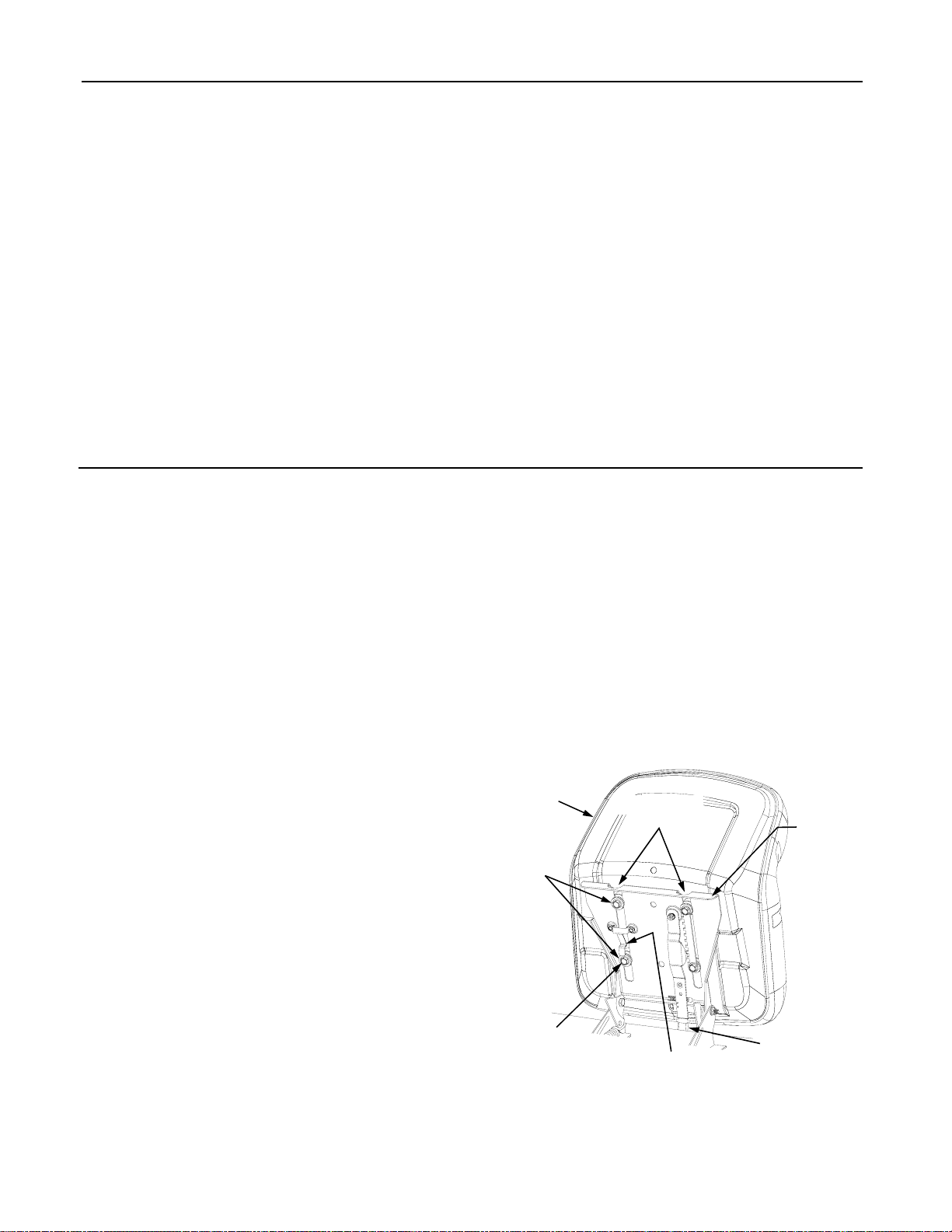
TABLE OF CONTENTS
TRACTOR PREPARATION ................................................................................................... 2
IMPORTANT SAFE OPERATION PRACTICES .................................................................... 4
SAFETY DECALS AND LABELS ........................................................................................... 7
RECORDING MODEL AND SERIAL NUMBER INFORMATION ........................................... 9
CUSTOMER SUPPORT ......................................................................................................... 9
TO THE OWNER..................................................................................................................... 9
SLOPE GAUGE .................................................................................................................... 10
SECTION 1: CONTROLS AND FEATURES ........................................................................ 11
SECTION 2: OPERATION ................................................................................................... 15
SECTION 3: ADJUSTMENTS .............................................................................................. 22
SECTION 4: MAINTENANCE .............................................................................................. 23
SECTION 5: MOWER DECK ............................................................................................... 28
SECTION 6: TROUBLE SHOOTING .................................................................................... 33
SECTION 7: REPLACEMENT PARTS ................................................................................. 34
SECTION 8: WARRANTY ...................................................................................................... 35
TRACTOR PREPARATION
Remove the upper crating material from the shipping
pallet, and cut any bands or tie straps securing the tractor to the pallet.
Use the lift handle to raise the deck to its highest position; engage the transmission bypass rods (Refer to
SECTION 1, page 10 CONTROLS AND FEATURES);
and carefully roll the tractor off the shipping pallet. Disengage the bypass rods.
Remove the deck wash system nozzle adapter and oil
drain tube from the manual bag and store for future use.
INSTALL OPERATOR’S SEAT
The operator’s seat was partially inserted into the seat
pivot bracket for shipping purposes. To install the seat
proceed as follows:
1. Cut any straps securing the seat assembly and the
drive control levers. Remove any packing material.
NOTE: The seat is partially inserted into the slot s of th e
seat pivot bracket. If the seat does not become disengaged from the pivot bracket when removing the packaging material, the pivot bracket may be pivot ed upward
and the seat pushed into place as described in ste p 6. If
the seat does disengage the pivot bracket, install the
seat as instructed in steps 2 through 6.
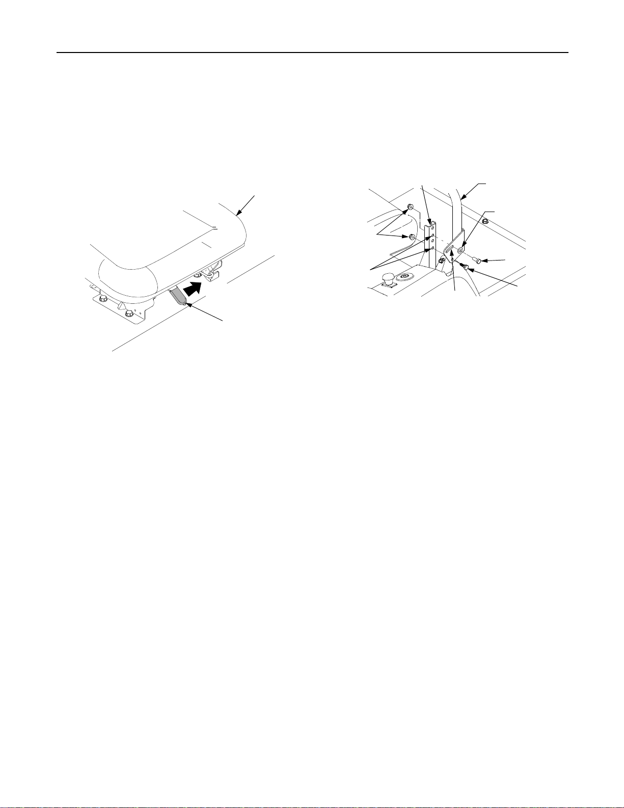
2. Pivot the seat pivot bracket partially upward. Refer
to Figure 1.
3. Note the grooves in the seat adjust spacers
attached to the bottom of the seat, then lift the seat
and position above and to the rear of the pivot
bracket.
4. Align the grooves in the seat adjust spacers with
the sides of the adjustment slots in the pivot
bracket.
5. Slide the seat adjust spacers into the slots of the
pivot bracket.
6. Continue to push the seat forward in the pivot
bracket until the front/left shoulder bolt of the seat
assembly passes forward of the stop bracket on
the seat pivot bracket. See Figure 1.
Use the seat adjust lever to adjust the seat position. Refer to "Adjusting the Operator’s Seat" in Section 3 for
seat adjustment instructions.
Seat
Seat
Adjust
Spacer
Front/Left
Shoulder Bolt
Adjustment
Slots
Stop Bracket
Figure 1
Seat
Pivot
Bracket
Seat Adjust
Lever
2
Page 3
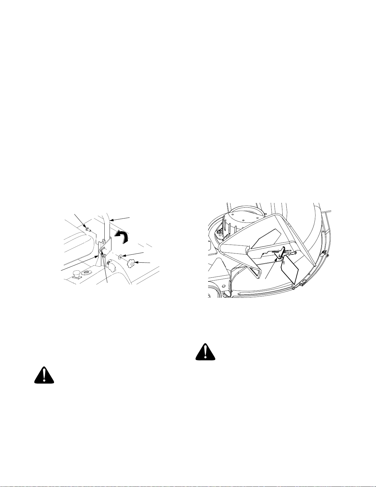
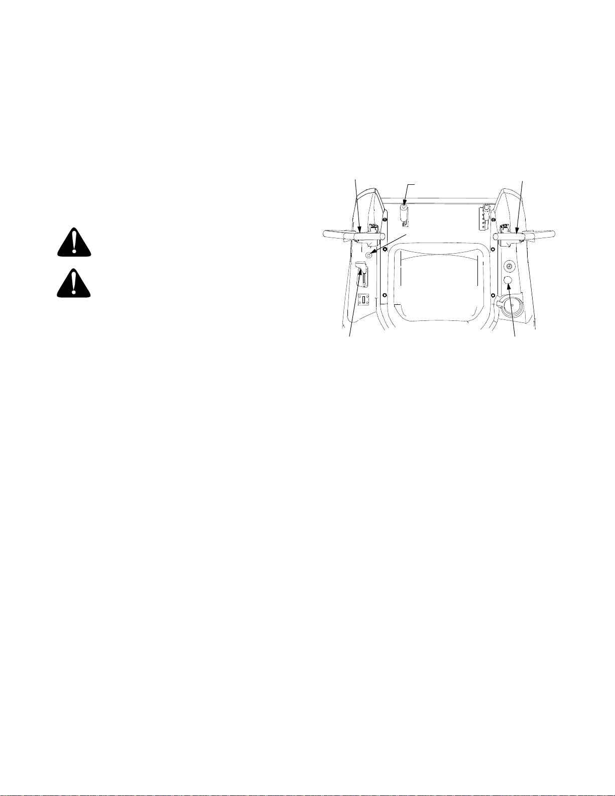
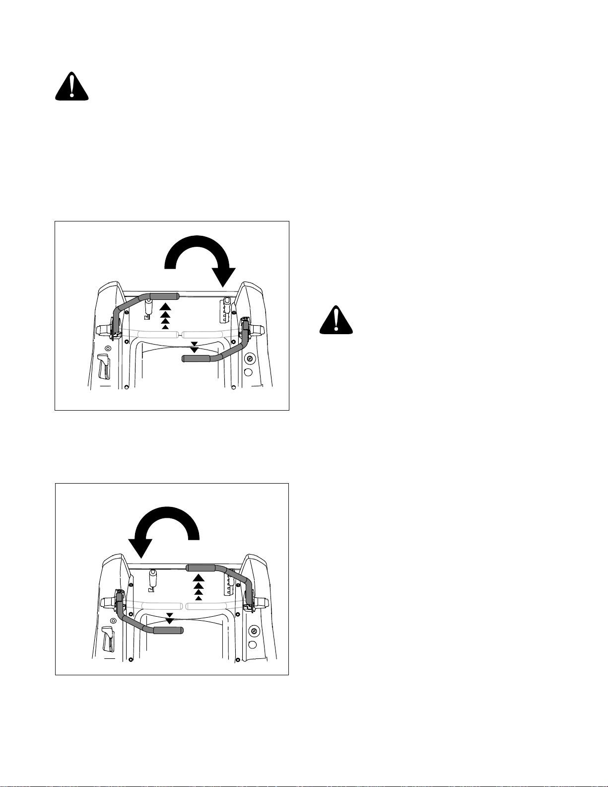
POSITION DRIVE CONTROL LEVERS
The drive control levers are unfastened from their respective pivot brackets and lowered for shipping purposes. The control levers must be repositioned and
secured to the pivot bracket to operate the tractor. Reposition the control levers as follows:
• Remove the nut knob, bell washer, and carriage
bolt from either of the two control lever pivot
brackets. Refer to Figure 2.
• Lift and swing that control lever upward until the
slotted hole in the lever bracket aligns with one of
the holes in the pivot bracket. Refer to Figure 2.
• From the inside, insert the carriage bolt into the
pivot bracket and through the control lever slot. See
Figure 2.
• Slide the bell washer onto the carriage bolt, then
thread the nut knob onto the bolt. Fully tighten the
knob to temporarily secure control lever (See Figure
2). Refer to "Adjusting the Drive Control Levers" in
Section 3 for instructions on final adjustment of the
levers.
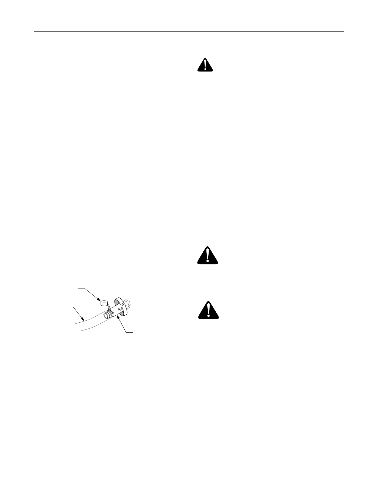
Carriage Bolt
Control Lever
The tractor is shipped with an activated sealed battery,
with the positive battery cable factory connected. The
negative cable must be connected.
NOTE: Make sure the ignition switch is in the "OFF" position before attaching the battery cable.
1. Pull the protective cap off the negative terminal of
the battery, and remove the hex cap screw and nut
from the free end of the negative battery cable.
2. Connect the negative battery cable (heavy black)
to negative terminal (NEG) of the battery using the
hex cap screw and nut. Slide the black terminal
cover over the negative terminal of the battery.
MODEL ZT42 ONLY
Remove The Chute Stop
• Locate the chute stop on the right side of the
mower, between discharge chute and cutting deck.
• While holding the discharge chute up, rotate the
chute stop clockwise and remove.
• Discard the chute stop.
Lift control
lever upward
Bell Washer
Nut Knob
Pivot
Bracket
Slotted
Hole
Figure 2
• Note the relative position of the control lever to the
pivot bracket, then repeat the previous steps to
reposition the other control lever in approximately
the same position.
CONNECT THE BATTERY
WARNING: Battery posts, terminals and
related accessories contain lead and lead
compounds. Wash hands after handling.
Chute Stop
Figure 3
MODEL ZT50 ONLY
Lower Deck Discharge Chute
WARNING: Never operate the mower deck
without the discharge chute installed and
in the down position.
Locate the cable tie holding the deck discharge chute in
the up position for shipping purposes. Cut the cable tie
and lower the discharge chute.
3
Page 4

IMPORTANT SAFE OPERATION PRACTICES
WARNING: This symbol points out impor-
tant safety instructions which, if not followed,
could endanger the personal safety and/or
property of yourself and others. Read and fol-
DANGER: This machine was built to be operated according to the rules for safe operation in this man-
ual. As with any type of power equipment, carelessness or error on the part of the operator can result in
serious injury. This machine is capable of amputating hands and feet and throwing objects. Failure to
observe the following safety instructions could result in serious injury or death.
GENERAL OPERATION
1. Read, understand, and follow all instructions on
the machine and in the manual(s) before
attempting to assemble and operate. Keep this
manual in a safe place for future and regular
reference and for ordering replacement parts.
2. Be familiar with all controls and their proper
operation. Know how to stop the machine and
disengage them quickly.
3. Never allow children under 14 years old to operate
this machine. Children 14 years old and over
should read and understand the operation
instructions and safety rules in this manual and
should be trained and supervised by a parent.
4. Never allow adults to operate this machine without
proper instruction.
5. To help avoid blade contact or a thrown object
injury, keep bystanders, helpers, children and pets
at least 75 feet from the machine while it is in
operation. Stop machine if anyone enters the area.
6. Thoroughly inspect the area where the equipment
is to be used. Remove all stones, sticks, wire,
bones, toys, and other foreign objects which could
be picked up and thrown by the blade(s). Thrown
objects can cause serious personal injury.
7. Plan your mowing pattern to avoid discharge of
material toward roads, sidewalks, bystanders and
the like. Also, avoid discharging material against a
wall or obstruction which may cause discharged
material to ricochet back toward the operator.
8. Always wear safety glasses or safety goggles
during operation and while performing an
adjustment or repair to protect your eyes. Thrown
objects which ricochet can cause serious injury to
the eyes.
9. Wear sturdy, rough-soled work shoes and closefitting slacks and shirts. Loose fitting clothes and
jewelry can be caught in movable parts. Never
operate this machine in bare feet or sandals.
10. Be aware of the mower and attachment discharge
direction and do not point it at anyone. Do not
operate the mower without the discharge cover or
entire grass catcher in its proper place.
low all instructions in this manual before attempting to
operate this machine. Failure to comply with these instructions may result in personal injury. When you see
this symbol—heed its warning.
11. Do not put hands or feet near rotating parts or
under the cutting deck. Contact with the blade(s)
can amputate hands and feet.
12. A missing or damaged discharge cover can cause
blade contact or thrown object injuries.
13. Stop the blade(s) when crossing gravel drives,
walks, or roads and while not cutting grass.
14. Watch for traffic when operating near or crossing
roadways. This machine is not intended for use on
any public roadway.
15. Do not operate the machine while under the
influence of alcohol or drugs.
16. Mow only in daylight or good artificial light.
17. Never carry passengers.
18. Back up slowly. Always look down and behind
before and while backing to avoid a back-over
accident. Be aware and pay attention to the safety
system function that stops power to the blades
when driving in reverse. If not functioning properly,
contact an authorized dealer for safety system
inspection and repair.
19. Slow down before turning. Operate the machine
smoothly. Avoid erratic operation and excessive
speed.
20. Disengage blade(s), set parking brake, stop
engine and wait until the blade(s) come to a
complete stop before removing grass catcher,
emptying grass, unclogging chute, removing any
grass or debris, or making any adjustments.
21. Never leave a running machine unattended.
Always turn off blade(s), place transmission in
neutral, set parking brake, stop engine and
remove key before dismounting.
22. Use extra care when loading or unloading the
machine into a trailer or truck. This unit should not
be driven up or down ramp(s), because the unit
could tip over, causing serious personal injury.
The unit must be pushed manually on ramp(s) to
load or unload properly.
23. Muffler and engine become hot and can cause a
burn. Do not touch.
24. Check overhead clearances carefully before
driving under low hanging tree branches, wires,
door openings etc., where the operator may be
struck or pulled from the unit, which could result in
serious injury.
4
Page 5

25. Disengage all attachment clutches, set parking
brake to the ’ON’ position and move the RH and
LH drive levers fully outward to the neutral position
before attempting to start engine.
26. Your machine is designed to cut normal residential
grass of a height no more than 10”. Do not attempt
to mow through unusually tall, dry grass (e.g.,
pasture) or piles of dry leaves. Dry grass or leaves
may contact the engine exhaust and/or build up on
the mower deck presenting a potential fire hazard.
27. Use only accessories and attachments approved
for this machine by the machine manufacturer.
Read, understand and follow all instructions
provided with the approved accessory or
attachment.
28. Data indicates that operators, age 60 years and
above, are involved in a large percentage of riding
mower-related injuries. These operators should
evaluate their ability to operate the riding mower
safely enough to protect themselves and others
from serious injury.
29. If situations occur which are not covered in this
manual, use care and good judgment. Contact
your authorized dealer for assistance.
SLOPE OPERATION
Slopes are a major factor related to loss of control and
tip-over accidents which can result in severe injury or
death. All slopes require extra caution. If you cannot
back up the slope or if you feel uneasy on it, do not
mow it.
For your safety, use the slope gauge included as part
of this manual to measure slopes before operating this
unit on a sloped or hilly area. If the slope is greater
than 15 degrees as shown on the slope gauge, do not
operate this unit on that area or serious injury could
result.
DO:
1. Mow up and down slopes, not across. Exercise
extreme caution when changing direction on
slopes.
2. Watch for holes, ruts, bumps, rocks, or other
hidden objects. Uneven terrain could overturn the
machine. Tall grass can hide obstacles.
3. Use slow speed. Choose a low enough speed
setting so that you will not have to stop or shift
while on the slope. Tires may lose traction on
slopes even though the brakes are functioning
properly.
Always keep machine in gear when going down
slopes to take advantage of engine braking action.
4. Follow the manufacturer’s recommendations for
wheel weights or counterweights to improve
stability.
5. Use extra care with grass catchers or other
attachments. These can change the stability of the
machine.
6. Keep all movement on the slopes slow and
gradual. Do not make sudden changes in speed or
direction. Rapid engagement or braking could
cause the front of the machine to lift and rapidly flip
over backwards which could cause serious injury.
DO NOT:
1. Do not turn on slopes unless necessary; then, turn
slowly and gradually downhill, if possible.
2. Do not mow near drop-offs, ditches or
embankments. The mower could suddenly turn
over if a wheel is over the edge of a cliff, ditch, or if
an edge caves in.
3. Do not try to stabilize the machine by putting your
foot on the ground.
4. Do not use a grass catcher on steep slopes.
5. Do not mow on wet grass. Reduced traction could
cause sliding.
6. Do not tow heavy pull behind attachments (e.g.
loaded dump cart, lawn roller, etc.) on slopes
greater than 5 degrees. When going down hill, the
extra weight tends to push the tractor and may
cause you to loose control. (e.g. tractor may speed
up, braking and steering ability are reduced,
attachment may jack-knife and cause tractor to
overturn).
CHILDREN
1. Tragic accidents can occur if the operator is not
alert to the presence of children. Children are often
attracted to the machine and the mowing activity.
They do not understand the dangers. Never
assume that children will remain where you last
saw them.
a. Keep children out of the mowing area and in
watchful care of a responsible adult other
than the operator.
b. Be alert and turn machine off if a child
enters the area.
c. To avoid back-over accidents, always look
behind and down for small children.
d. Never carry children, even with the blade(s)
shut off. They may fall off and be seriously
injured or interfere with safe machine
operation.
e. Use extreme care when approaching blind
corners, doorways, shrubs, trees or other
objects that may block your vision of a child
who may run into the machine.
f. Keep children away from hot or running
engines. They can suffer burns from a hot
muffler.
g. Remove key when machine is unattended
to prevent unauthorized operation.
5
Page 6

2. Never allow children under 14 years old to operate
the machine. Children 14 years old and over
should read and understand the operation
instructions and safety rules in this manual and
should be trained and supervised by a parent.
TOWING
1. Tow only with a machine that has a hitch designed
for towing. Do not attach towed equipment except
at the hitch point.
2. Follow the manufacturers recommendation for
weight limits for towed equipment and towing on
slopes.
3. Never allow children or others in or on towed
equipment.
4. On slopes, the weight of the towed equipment may
cause loss of traction and loss of control.
5. Travel slowly and allow extra distance to stop.
6. Do not shift to neutral and coast downhill.
SERVICE
SAFE HANDLING OF GASOLINE:
1. To avoid personal injury or property damage
use extreme care in handling gasoline. Gasoline
is extremely flammable and the vapors are
explosive. Serious personal injury can occur when
gasoline is spilled on yourself or your clothes
which can ignite. Wash your skin and change
clothes immediately.
a. Use only an approved gasoline container.
b. Never fill containers inside a vehicle or on a
truck or trailer bed with a plastic liner.
Always place containers on the ground
away from your vehicle before filling.
c. When practical, remove gas-powered
equipment from the truck or trailer and
refuel it on the ground. If this is not possible,
then refuel such equipment on a trailer with
a portable container, rather than from a
gasoline dispenser nozzle.
d. Keep the nozzle in contact with the rim of
the fuel tank or container opening at all
times until fueling is complete. Do not use a
nozzle lock-open device.
e. Extinguish all cigarettes, cigars, pipes and
other sources of ignition.
f. Never fuel machine indoors.
g. Never remove gas cap or add fuel while the
engine is hot or running. Allow engine to
cool at least two minutes before refueling.
h. Never over fill fuel tank. Fill tank to no more
than ½ inch below bottom of filler neck to
allow space for fuel expansion.
i. Replace gasoline cap and tighten securely.
j. If gasoline is spilled, wipe it off the engine
and equipment. Move unit to another area.
Wait 5 minutes before starting the engine.
k. To reduce fire hazards, keep machine free
of grass, leaves, or other debris build-up.
Clean up oil or fuel spillage and remove any
fuel soaked debris.
l. Never store the machine or fuel container
inside where there is an open flame, spark
or pilot light as on a water heater, space
heater, furnace, clothes dryer or other gas
appliances.
m. Allow a machine to cool at least 5 minutes
before storing.
GENERAL SERVICE:
1. Never run an engine indoors or in a poorly
ventilated area. Engine exhaust contains carbon
monoxide, an odorless, and deadly gas.
2. Before cleaning, repairing, or inspecting, make
certain the blade(s) and all moving parts have
stopped. Disconnect the spark plug wire and
ground against the engine to prevent unintended
starting.
3. Periodically check to make sure the blades come
to complete stop within approximately (5) five
seconds after operating the blade disengagement
control. If the blades do not stop within the this
time frame, your unit should be serviced
professionally by an authorized dealer.
4. Regularly check the safety interlock system for
proper function, as described later in this manual.
If the safety interlock system does not function
properly, have your machine serviced
professionally by an authorized dealer.
5. Check the blade(s) and engine mounting bolts at
frequent intervals for proper tightness. Also,
visually inspect blade(s) for damage (e.g.,
excessive wear, bent, cracked).
Replace the blade(s) with the original equipment
manufacturer’s (O.E.M.) blade(s) only, listed in
this manual. “Use of parts which do not meet the
original equipment specifications may lead to
improper performance and compromise safety!”
6. Mower blades are sharp. Wrap the blade or wear
gloves, and use extra caution when servicing
them.
7. Keep all nuts, bolts, and screws tight to be sure the
equipment is in safe working condition.
8. Never tamper with the safety interlock system or
other safety devices. Check their proper operation
regularly.
9. After striking a foreign object, stop the engine,
disconnect the spark plug wire(s) and ground
against the engine. Thoroughly inspect the
machine for any damage. Repair the damage
before starting and operating.
10. Never attempt to make adjustments or repairs to
the machine while the engine is running.
6
Page 7
11. Grass catcher components and the discharge
cover are subject to wear and damage which could
expose moving parts or allow objects to be thrown.
For safety protection, frequently check components and replace immediately with original equipment manufacturer’s (O.E.M.) parts only, listed in
this manual. “Use of parts which do not meet the
original equipment specifications may lead to
improper performance and compromise safety!”
12. Do not change the engine governor settings or
over-speed the engine. The governor controls the
maximum safe operating speed of the engine.
13. Maintain or replace safety and instruction labels,
as necessary.
14. Observe proper disposal laws and regulations for
gas, oil, etc. to protect the environment.
Spark Arrestor
WARNING: This machine is equipped with
an internal combustion engine and should
not be used on or near any unimproved forest-covered, brushcovered or grass-covered
land unless the engine’s exhaust system is
equipped with a spark arrester meeting applicable local or provincial laws (if any).
If a spark arrester is used, it should be maintained in
effective working order by the operator.
A spark arrester for the muffler is available through
your nearest engine authorized service dealer.
Do not modify engine
To avoid serious injury or death, do not modify engine
in any way. Tampering with the governor setting can
lead to a runaway engine and cause it to operate at unsafe speeds. Never tamper with factory setting of engine governor.
Notice regarding Emissions
Engines which are certified to comply with California
and federal EPA emission regulations for SORE (Small
Off Road Equipment) are certified to operate on regular unleaded gasoline, and may include the following
emission control systems: Engine Modification (EM)
and Three Way Catalyst (TWC) if so equipped.
Average Useful Life
According to the Consumer Products Safety Commission (CPSC) and the U.S. Environmental Protection
Agency (EPA), this product has an
Average Useful Life of
seven (7) years, or 60 hours of operation. At the end of
verage Useful Life, buy a new machine or have the
the
machine inspected annually by an authorized service
dealer to ensure that all mechanical and safety systems are working properly and not worn excessively.
Failure to do so can result in accidents, injuries or
death.
WARNING: YOUR RESPONSIBILITY Restrict the use of this power machine to persons who read,
understand and follow the warnings and instructions in this manual and on the machine.
R
+
N
=
F
4
3 51
P
2
S30296
kg
MAX 20
%
S30544
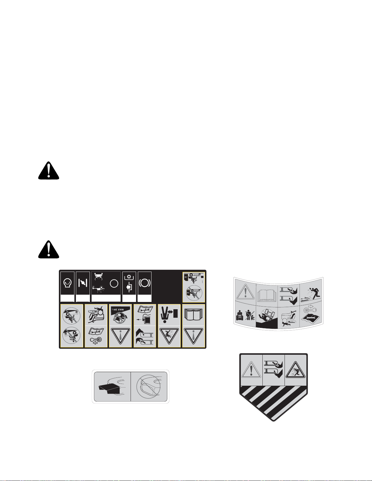
Safety Labels found on your unit
7
Page 8

RECORDING MODEL AND SERIAL NUMBER
This Operator’s Manual is an important part of your new lawn tractor. It will help you assemble, prepare and
maintain the unit for best performance. Please read and understand what it says.
Before you start assembling your new equipment, please locate the model plate on the
equipment and copy the information from it in the space provided below. The information on the
model plate is very important if you need help from your authorized dealer.
• You can locate the model number by looking beneath the seat. A sample model plate is explained below.
Model Number
Numéro de modèle
XXX-XXXXXX
Serial Number
Numéro de série
XXXXXXXXXXX
CUB CADET CANADA
KITCHENER, ON N2G 4J1
Copy the model number here:
Copy the serial number here:
ENGINE INFORMATION
The engine manufacturer is responsible for all engine-related issues with regards to performance, power-rating, specifications,
warranty and service. Please refer to the engine manufacturer’s Owner’s/Operator’s Manual packed separately with your unit for
more information.
CALLING CUSTOMER SUPPORT
If you have difficulty assembling this product or have any questions regarding the controls, operation or
maintenance of this unit, you can seek help from the experts. Choose from the options below:
1. Visit www.cubcadet.ca for many useful suggestions, click on Customer Support button.
2. Call a Customer Support Representative at 1-800-668-1238.
Please have your unit’s model number and serial number ready when you call. See previous section to locate
this information. You will be asked to enter the serial number in order to process your call.
8
Page 9
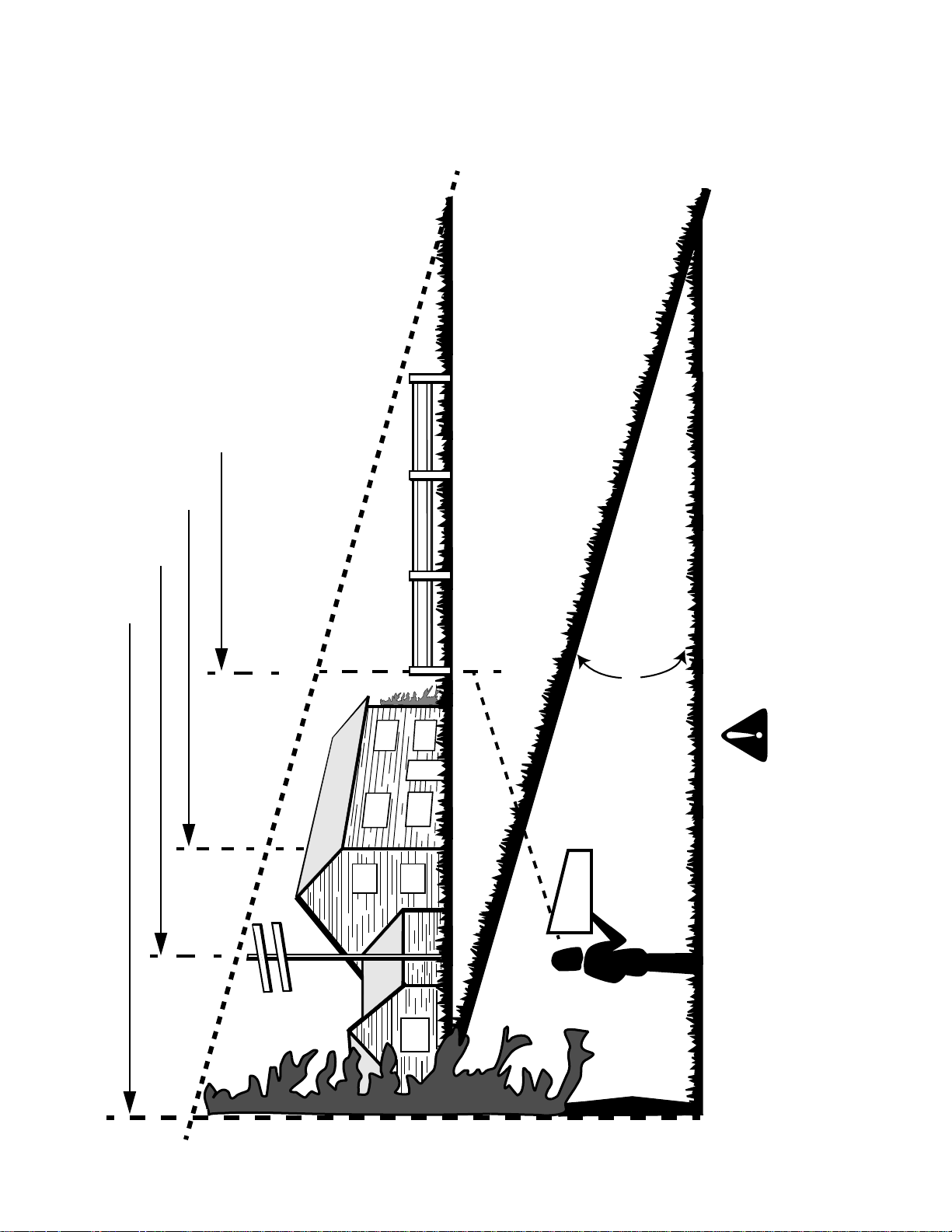
(Keep this sheet in a safe place for future reference.)
A CORNER OF A BUILDING
A POWER POLE
SIGHT AND HOLD THIS LEVEL WITH A VERTICAL TREE
SLOPE GAUGE
E
OP
L
S
°
E
P
R
E
S
E
N
5
1
A
G
N
I
T
OR A FENCE POST
OT
D
R
,
E
N
I
L
D
E
T
15°
WARNING
USE THIS PAGE AS A GUIDE TO DETERMINE SLOPES WHERE YOU MAY NOT OPERATE SAFELY.
F
O
D
L
ON
Do not mow on inclines with a slope in excess of 15 degrees (a rise of approximately 2-1/2 feet every 10 feet).
A riding mower could overturn and cause serious injury. If operating a walk-behind mower on such a slope, it is
extremely difficult to maintain your footing and you could slip, resulting in serious injury.
Operate RZT zero turn tractors across the face of slopes rather than up and down. Begin with the first pass
across the bottom of the slope and turn uphill at the end of each pass whenever possible.
9
Page 10
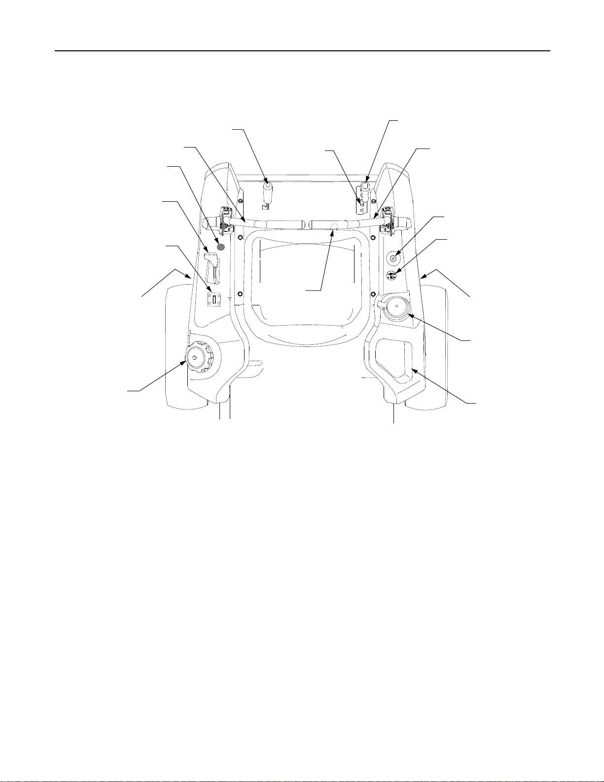
SECTION 1: CONTROLS AND FEATURES
O
C
N
M
L
F
K
A
J
B
C
D
E
F
G
H
A.
Deck Lift Handle
B.
RH and LH Drive Control Levers
C.
D.
Ignition Switch
E.
PTO Switch
F.
Transmission Bypass Rod (Not Shown)
G. Cup Holder
Figure 4
H.Deck Height Index
J.
K.
L.
M.
N.
O. Parking Brake Engagement Lever
10
Storage Tray
Seat Adjustment Lever (Not Seen)
Fuel Tank Cap
Hour Meter /Indicator Panel
Throttle Control
Choke Control—Model ZT50 ONLY
Page 11
NOTE: References to LEFT, RIGHT, FRONT, and
REAR indicate that position on the tractor when
facing forward while seated in the operator’s seat.
A. Deck Height Index
The deck height index consists of six index notches
located on the front/right of the seat box frame. Each
notch corresponds to a 1/2 inch change in the deck
height position ranging from 1-1/2 inches at the lowest notch to 4 inches at the highest notch.
B. Deck Lift Handle
The deck lift handle is located on the front/right of the
seat box frame, and is used to raise and lower the
mower deck.
Pull the handle to the left out of the index notch and
push downward to lower the deck, or pull upward to
raise the deck. When the desired height is attained,
move the lift handle to the right until fully in the index
notch.
C. RH and LH Drive Control Levers
The RH and LH control levers are located to each
side of the operator’s seat. These hinged levers open
out to the side in the neutral position to permit the
operator to be seated or to leave the tractor seat. The
levers must be fully opened out in the neutral position
to start the tractor engine.
Each lever controls the respective RH or LH transmission. Consequently, these levers control all of the
movements of the tractor. Driving and steering utilizing these control levers is quite different from
conventional tractors, and will take some practice to
master. Refer to SECTION 2: OPERATION for
instructions on using the control levers.
D. Ignition Switch
The ignition switch is located on the RH console to
the right of the operator’s seat.
The ignition switch has three positions as follow:
OFF
STOP
ON
NOTE: To prevent accidental starting and/or battery
discharge, remove the key from the ignition switch
when the tractor is not in use.
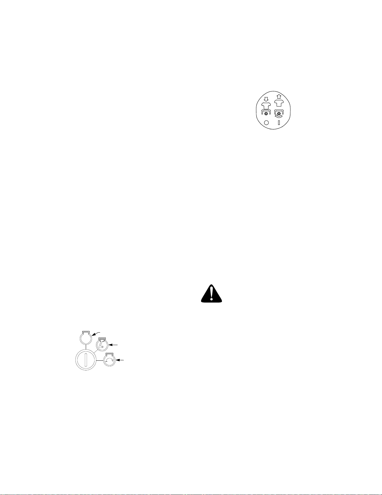
E. Power Take-Off (PTO) Switch
The PTO switch is located on the RH console to the
right of the operator’s seat.
Figure 6
The PTO switch operates the electric PTO clutch
mounted on the bottom of the engine crankshaft. Pull
the switch knob upward to engage the PTO clutch, or
push the knob downward to disengage the clutch.
The PTO switch must be in the "disengaged" position
when starting the engine.
F. Transmission Bypass Rods (Not Shown)
The transmission bypass rods (one for each the RH
and LH transmission) are located beneath the frame
platform, just inside each rear wheel.
When engaged, the two rods open a bypass within the
hydrostatic transmissions, which allows the tractor to
be pushed short distances by hand. Refer to
SECTION 4: MAINTENANCE for instructions on
using the bypass feature.
WARNING: Never tow your tractor.
Towing the tractor with the rear wheels
on the ground may cause severe damage
to the transmissions.
G. Cup Holder
The cup holder is located toward the rear of the RH
console to the right of the operator’s seat.
START
Figure 5
OFF - The engine and electrical system is turned off.
ON - The tractor electrical system is energized.
START- The starter motor will turn over the engine.
Release the key immediately when the
engine starts
H. Storage T ray
The storage tray is located at the rear of the RH
console.
J. Seat Adjustment Lever (Not Seen)
The seat adjustment lever is located below the front/
left of the seat. The lever allows for adjustment of the
fore to aft position of the operator’s seat. Refer to
SECTION 3: ADJUSTMENTS for instructions on
adjusting the seat position.
11
Page 12
K. Fuel Tank Cap
The fuel tank cap is located at the rear of the LH
console. Turn the cap counterclockwise to unscrew
and remove from the fuel tank. Always re-install the
fuel cap tightly onto the fuel tank after removing.
WARNING: Never fill the fuel tank when
the engine is running. If the engine is hot
from recently running, allow to cool for
several minutes before refueling. Highly
flammable gasoline could splash onto
the engine and cause a fire.
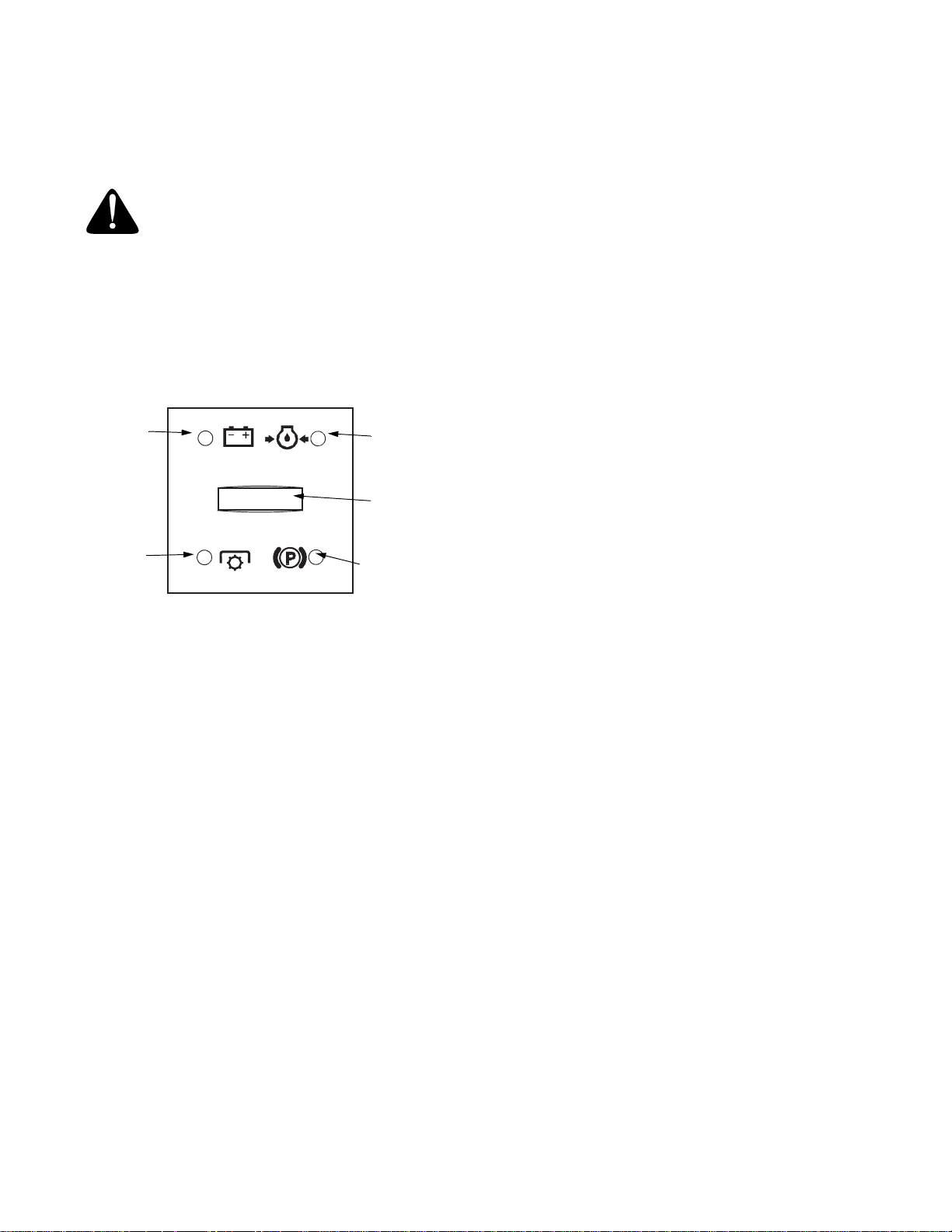
L. Hour Meter/Indicator Panel
The hour meter/indicator panel is located on the LH
console to the left of the operator’s seat.
52, 100-102, 150-152, etc.). The LCD will flash as
described for five minutes every time the tractor’s engine is started during this maintenance
interval. Follow the oil change intervals pro-
vided in the engine owner’s manual.
Indicator Panel Feature
Battery Indicator (Refer to Figure 7)
• Illuminates and the battery voltage is displayed
briefly when the ignition switch it turned to the
"ON" position.
• Illuminates to indicate the battery voltage has
dropped below 11.5 (+0.5/-1.0) volts. The battery
voltage is also displayed on the hour meter. If this
indicator and display come on during operation,
check the battery and charging system for possible causes and/or contact your dealer.
Battery
Indicator
PTO
Engaged
Indicator
Oil Pressure
Indicator
(optional)
Hour
Meter
Parking Brake
Engaged
Indicator
Figure 7
Hour Meter Feature
The hour meter records the hours that the tractor has
been operated in the digital display (tenths of an
hour-right most digit).
NOTE: The hour meter is activated whenever the igni-
tion switch is turned to the "ON" position. Keep a
record of the actual hours of operation to assure all
maintenance procedures are completed according to
the instructions in this manual and the engine manual.
• When key is turned to the "ON" position, the
battery indicator light briefly illuminates and the
battery voltage is briefly displayed. The display
then changes to the accumulated hours.
• The Indicator Monitor will also remind the operator of maintenance intervals for changing the
engine oil. The LCD will alternately flash, “CHG” ;
“OIL” and the recorded hours for five minutes
after every 50 hours of recorded operation. The
maintenance interval lasts for two hours (from 50-
Oil Pressure Indicator (Refer to Figure 7) (optional)
• This warning lamp indicates low engine oil pressure. If the indicator comes on while the engine
is running, stop the engine immediately and
check for possible causes. Do not run the engine
while this indicator is illuminated. Contact your
dealer to have the tractor and engine inspected.
NOTE: The oil pressure indicator may illuminate
when the ignition switch is in the ON position, but
should turn off when the engine is started.
PTO Engaged Indicator (Refer to Figure 7)
• This indicator illuminates when the PTO switch is
pulled upward in the "ENGAGED" position and
the ignition switch is turned to the "START"
position. Check this indicator if the engine will not
crank with the ignition switch in the "START"
position. If necessary, move the PTO switch to
the "DISENGAGED" position.
Parking Brake Engaged Indicator (Refer to Figure 7)
• This indicator illuminates when the parking brake
is in the DISENGAGED position and the ignition
switch is turned to the "START" position. Check
this indicator if the engine will not crank with the
ignition switch in the "START" position. If necessary, move the parking brake to the ENGAGED
position.
This indicator also illuminates when the ignition
switch is turned to the "START" position and the
RH and/or LH drive control levers are in a position other than the fully out in neutral position.
Move the control levers fully outward.
12
Page 13
M. Throttle Control
The throttle control is located on the LH console to
the left of the operator’s seat. When set in a given
position, a uniform engine speed will be maintained.
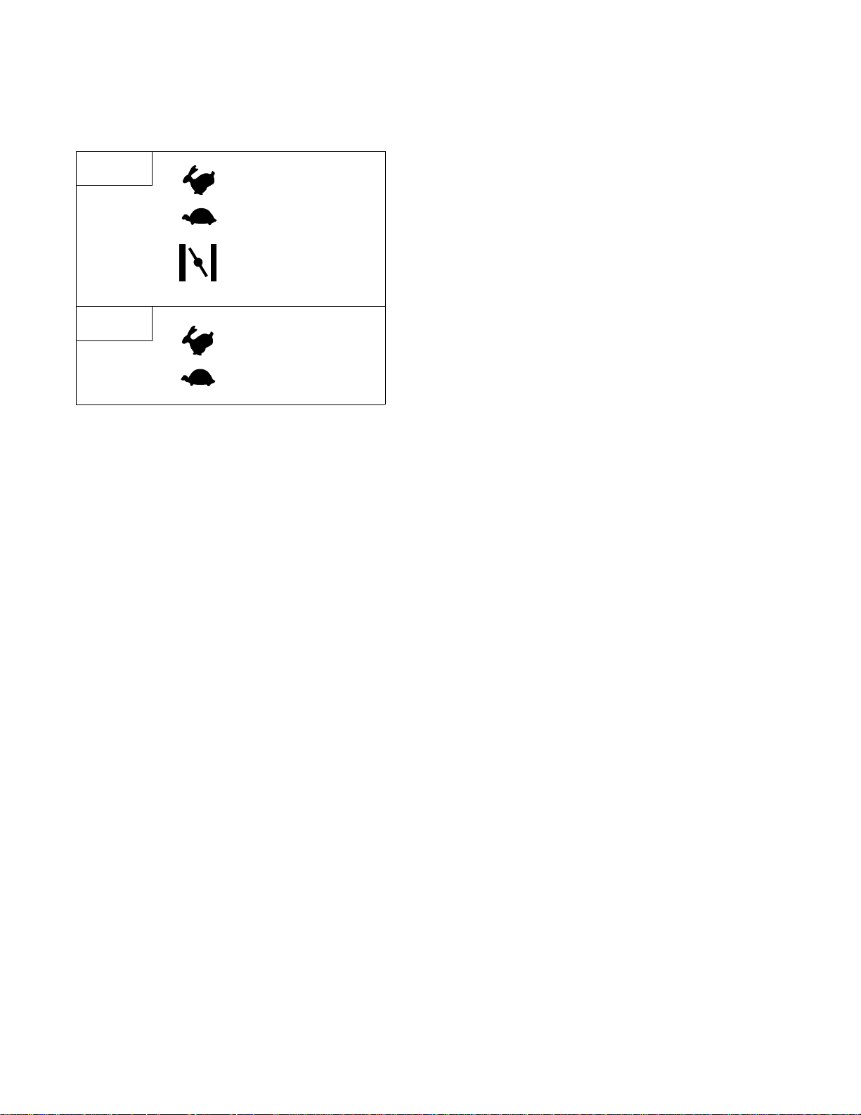
ZT42
CHOKE
ZT50
This symbol indicates the
fast position.
This symbol indicates the
slow position.
This symbol indicates the
choke position.
This symbol indicates the
fast position.
This symbol indicates the
slow position.
Figure 8
• Push the throttle control handle forward to increase the engine speed. The tractor is designed
to operate with the control handle in the fast
position (full throttle) when the tractor is driven
and the mower deck is engaged.
• Pull the throttle control handle rearward to decrease the engine speed.
• Model ZT42 ONLY — When starting the engine,
push the control handle fully forward into the
"CHOKE" position. See Figure 8. After starting
and warming the engine, move the control handle
rearward until you feel it move past the choke
detent.
N. Choke Control - Model ZT50 ONLY
The choke knob controls the position of the engine
choke. Pull the knob out to choke the engine; push the
knob in to open the choke.
O. Parking Brake Engagement Lever
The parking brake engagement lever is located on
the front/left of the seat box frame, and is used to
engage the parking brake.
• Pull the lever fully upward and to the left and
lower into the "J" slot to engage the parking
brake.
• Pull the lever up out of the "J" slot and to the
right; then lower completely to disengage the
parking brake.
IMPORTANT: If the LH and RH drive control levers
are not fully opened out in the ne utral position when
engaging the parking brake, the engine will stop. The
parking brake must be placed in the engaged position
when starting the tractor engine.
13
Page 14

SECTION 2: OPERATION
GENERAL SAFETY
• RECEIVE INSTRUCTION - Read the operator’s
manual. Learn to operate this machine SAFELY.
Don’t risk INJURY or DEATH. Allow only those
who have become competent in its usage to
operate this tractor .
• Before starting the engine or beginning operation,
be familiar with the controls. The operator should
be in the operator’s seat. The PTO switch must
be in the disengaged position, the parking brake
engaged, and the RH and LH drive control levers
moved fully outward in the neutral position.
• Keep all shields in place. Keep away from moving
parts.
• NO RIDERS! Keep all people and pets a safe
distance away. Look behind and down to both
sides of the tractor before and while backing up.
• DO NOT direct the mower discharge at people.
• Avoid slopes where possible. Never operate on
slopes greater than 15°. Slopes with a greater
incline present dangerous operating conditions.
Tractors can be rolled over.
• Before leaving the operator’s seat: Shut off the
PTO, move the RH and LH drive control levers
fully outward in the neutral position, engage the
parking brake, shut off the engine and remove
the ignition key. Wait for all movement to stop
before servicing or cleaning.
• Operate the drive control levers smoothly and
avoid any sudden movements of the levers
when starting and stopping. Keep a firm grip on
the control levers.
• Be careful when operating near roadways. Stop
the tractor motion and wait for vehicles to pass
before operating along the road.
• Do not operate the tractor with the mower deck
removed. Removal of the deck will change the
balance of the tractor, and could contribute to a
tractor rollover.
• Avoid operation on traction surfaces that are
unstable; use extreme caution if the surface is
slippery.
• Slow down before turning and come to a
complete stop before any zero turn maneuver.
• Do not stop the tractor or park the tractor over
combustible materials such as dry grass, leaves,
debris, etc.
• Do not fill the fuel tank when the engine is
running or while the engine is hot. Allow the
engine several minutes to cool before refueling.
Tighten the fuel cap securely.
BEFORE OPERATING YOUR TRACTOR
• Before you operate the tractor, study this manual
carefully. It has been prepared to help you
operate and maintain your tractor efficiently.
• This engine is certified to operate on unleaded
gasoline. For best results, fill the fuel tank with
only clean, fresh, unleaded regular or premium
gasoline. DO NOt use leaded gasoline.
• Some fuels are gasoline blended with alcohols or
ethers. The maximum alcohol percentage for ethanol and gasahol blends is 10%. The maximum
ether percentage for MTBE or ETBE blends is
15%. If undesirable operating symptoms occur,
use gasoline with a lower percentage of alcohol
or ether. Do not use gasoline that contains
Methanol.
• Check the engine oil level. See Engine Manual.
IMPORTANT: Your tractor is shipped with motor
oil in the engine. However, you MUST check the
oil level before operating. The capacity of the
engine and oil filter is approximately 62 oz. (1.83
liters) for the model ZT42 and 80 oz. (2.36 liters).
for the model ZT50. Be careful not to overfill.
• Clean the air cleaner element if necessary. See
Engine Manual.
• Check the tire inflation pressures.
• Adjust the seat for operator’s maximum comfort,
visibility, and for maintaining complete control of
the tractor.
SAFETY INTERLOCK SYSTEM
This tractor is equipped with a safety interlock system
for the protection of the operator. If the interlock system
should ever malfunction, do not operate the tractor.
Contact your authorized Dealer.
• The safety interlock system prevents the engine
from cranking or starting unless the RH and LH
drive control levers are moved fully outward in the
neutral position, the parking brake is engaged,
and the PTO is disengaged.
• To avoid sudden movement when disengaging
the parking brake, the safety interlock system will
shut off the engine if the RH and/or LH drive
control levers are moved to a position other than
the fully out in neutral position when the parking
brake is engaged
• The safety interlock system will shut off the
engine if the operator leaves the seat before
engaging the parking brake.
14
Page 15
• The safety interlock system will shut off the
engine if the operator leaves the seat with the
PTO engaged, regardless of whether the parking
brake is engaged.
NOTE: The PTO switch must be moved to the
“OFF” position to restart the engine.
• The safety interlock system will shut off the PTO
and the mower blades will stop if both drive control levers are moved into the reverse position.
The PTO will re-engage when one or both of the
levers are moved back to the neutral or forward
position.
STARTING THE ENGINE
WARNING: For personal safety, the
operator must be sitting in the tractor
seat when starting the engine.
WARNING: This unit is equipped with a
safety interlock system designed for the
protection of the operator. Do not operate the tractor if any part of the interlock
system is malfunctioning. Periodically
check the functions of th e interlock system for proper operation.
• Move the RH and LH drive control levers fully
outward in the neutral position. Refer to Figure 9.
• Operator must be sitting in the tractor seat.
• Engage the parking brake. Refer to Figure 9.
• Make certain the PTO switch is in the disengaged (down) position. Refer to Figure 9.
• Model ZT42 ONLY
1. Move the throttle control lever fully forward
into the "CHOKE" position. NOTE: If the
engine is warmed up, it may not be ne cessary
to place the throttle control in the choke
position.
2. Turn the ignition key clockwise to the “START”
position and release it as soon as the engine
starts; however, do not crank the engine continuously for more than 5 seconds at a time. If
the engine does not start within this time, turn
the key to “OFF” and wait a minute. Try again
after waiting.
3. After the engine starts, gradually pull the
throttle control lever rearward past the choke
detent position to the FAST position. Do not
use the choke to enrich the fuel mixture,
except as necessary to start the engine.
• Model ZT50 ONLY
1. Pull the choke control knob upward to the full
choke position. NOTE: If the engine is warmed
up, it may not be necessary to choke the
engine.
2. Move the throttle control lever fully forward to
the "fast" position.
LH Control Lever
Out in Neutral
ZT42 - Move Throttle
Control to Choke
ZT50 - Move Throttle
Control to "FAST"
Parking Brake
Engaged
ZT50 - Pull Choke
RH Control Lever
Out in Neutral
PTO Switch in Down
(Disengaged) Position
Figure 9
3. Turn the ignition key clockwise to the “START”
position and release it as soon as the engine
starts; however, do not crank the engine
continuously for more than 5 seconds at a
time. If the engine does not start within this
time, turn the key to “OFF” and wait a minute
to allow the engine’s starter motor to cool. Try
again after waiting.
4. As the engine warms up, gradually push the
choke knob downward to open the choke. Do
not use the choke to enrich the fuel mixture,
except as necessary to start the engine.
• Allow the engine to run for a few minutes at mid
throttle before putting the engine under load.
• Observe the hour meter/indicator panel. If the
battery indicator light comes on, immediately stop
the engine. Have the tractor inspected by your
dealer.
15
Page 16

COLD WEATHER STARTING
When starting the engine at temperatures near or
below freezing, ensure the correct viscosity motor oil
is used in the engine and the battery is fully charged.
Start the engine as follows:
• Be sure the battery is in good condition. A warm
battery has much more starting capacity than a
cold battery.
• Use fresh winter grade fuel. Winter grade
gasoline has higher volatility to improve starting.
Do not use gasoline left over from summer.
• Follow the previous instruction for STARTING
THE ENGINE.
USING JUMPER CABLES TO START ENGINE
WARNING: Batteries contain sulfuric acid
and produce explosive gasses. Make
certain the area is well ventilated, wear
gloves and eye protection, and avoid
sparks or flames near the battery.
If the battery charge is not sufficient to crank the
engine, recharge the battery. If a battery charger is
unavailable and the tractor must be started, the aid of
a booster battery will be necessary. Connect the
booster battery as follows:
• Connect the end of one cable to the disabled
tractor battery’s positive terminal; then connect
the other end of that cable to the booster
battery’s positive terminal.
• Connect one end of the other cable to the booster
battery’s negative terminal; then connect the
other end of that cable to the frame of the disabled tractor, as far from the battery as possible.
• Start the disabled tractor following the normal
starting instructions previously provided; then
disconnect the jumper cables in the exact reverse
order of their connection.
• Have the tractor’s electrical system checked and
repaired as soon as possible to eliminate the
need for jump starting.
STOPPING THE ENGINE
• Place the PTO switch in the “OFF” position.
• Move the RH and LH drive control levers fully
outward in the neutral position.
• Engage the parking brake.
• Place the throttle control lever in the slow (idle)
position. Run the engine for a short time to let
engine speed stabilize at the idle speed.
• Turn the ignition key to the “OFF” position and
remove the key from the ignition switch.
NOTE:
switch to prevent accidental starting or battery
discharge if the equipment is left unattended.
PRACTICE OPERATION (INITIAL USE)
Operating a zero-turn tractor is not like operating a
conventional type riding tractor. Although and because a zero-turn tractor is more maneuverable, getting used to operating the control levers takes some
practice.
We strongly recommend that you locate a reasonably large, level and open "practice area" where there
are no obstructions, pedestrians, or animals. You
should practice operating the tractor for a minimum of
30 minutes.
Carefully move (or have moved) the tractor to the
practice area. When performing the practice session,
the PTO should not be engaged. While practicing,
operate the tractor at approximately 1/2-3/4 throttle
and at less than full speed in both forward and
reverse.
Carefully practice maneuvering the tractor using the
instructions in the following section "Driving the Tractor." Practice until you are confident that you can
safely operate the tractor.
DRIVING THE TRACTOR
• Adjust the operator’s seat to the most
• Release the parking brake.
Always remove the key from the ignition
WARNING: Avoid sudden starts, excessive speed and sudden stops.
WARNING: Do not leave the seat of the
tractor without disengaging the PTO,
moving drive control levers fully outward
in the neutral position, and engaging the
parking brake. If leaving the tractor
unattended, turn the ignition key off and
remove key.
comfortable position that allows you to operate
the controls. See seat adjustment in the
ADJUSTMENTS section.
16
Page 17
• Move the RH and LH drive control levers inward
in the neutral position. See Figure 10.
Control Lever Moved
Inward and in Neutral
Figure 10
NOTE: If the control levers are not e ven in the neu tral
position, refer to Section 3 and adjust the levers so
that they are even.
• Move the throttle control lever forward to the full
throttle position (3500-3600 RPM).
NOTE: The tractor and engine are designed to run at
full throttle. If performing a practice session, it is
preferable that the tractor is operated at less than full
throttle (approximately 2500-3000 RPM), but this only
applies to practice operation.
NOTE: For Model ZT42, make certain the throttle
control has not been moved too far forward into the
"Choke" position.
WARNING: Always maintain a firm grip
on the control levers. DO NOT release the
control levers to slow or stop the tractor;
move the levers to the neutral position
using your hands.
• To drive the tractor, firmly grasp the respective
drive control levers with your right and left hands
and proceed as follows :
Driving the Tractor Forward
WARNING: Keep all movement of the
drive control levers slow and smooth.
Abrubt movement of the control levers
can affect the stability of the tractor and
could cause the tractor to flip over,
which may result in serious injury or
death to the operator.
• Slowly and evenly move both drive control levers
forward. The tractor will start to move forward.
See Figure 11.
• As the control levers are pushed farther forward
the speed of the tractor will increase.
DRIVING FORWARD
Faster
Slower
Neutral
Position
Figure 11
• To slow the tractor move the controls lever
rearward to attain the desired speed, or move the
levers to the neutral position to stop the tractor.
IMPORTANT: Always maintain your grasp on the
drive control levers. Do not release the levers to
slow the tractor or to return to neutral.
Turning the Tractor While Driving Forward
WARNING: When reversing the direction
of travel, we recommend performing
gradual ‘U’ turns where possible.
Sharper turns increase the possibility of
turf defacement, and could affect control
of the tractor. ALWAYS slow the tractor
before making sharp turns.
• To turn the tractor while driving forward, move the
control levers as necessary so that one lever is
rearward of the other. The tractor will turn in the
direction of the rearward control lever.
- To turn to the left, move the left drive control
lever rearward of the right lever. See Figure 12.
FORWARD LEFT TURN
Figure 12
17
Page 18
- To turn to the right, move the right drive control
lever rearward of the left lever. See Figure 13.
FORWARD RIGHT TURN
Figure 13
• The greater the fore-to-aft distance between the
two levers, the sharper the tractor will turn.
• To execute a "pivot turn," move the turn side
drive control lever to the neutral position, while
moving the other control lever forward.
IMPORTANT: Making a "pivot turn" on grass
will greatly increase the potential for
defacement of the turf.
IMPORTANT: Always maintain your grasp on the
drive control levers. Do not release the levers to
slow the tractor or to return to neutral.
Turning While Driving Rearward
• To turn the tractor while driving rearward, move
the control levers as necessary so that one lever
is forward of the other. The tractor will turn in the
direction of the forward control lever.
- To turn to the left while traveling in reverse,
move the left drive control lever forward of the
right lever. See Figure 15.
REARWARD LEFT TURN
Driving the Tractor In Reverse
WARNING: Always look behind and
down on both sides of the tractor before
backing up. Always look behind while
traveling in the reverse direction.
• Slowly and evenly move both drive control levers
rearward. The tractor will start to move in the
reverse direction. See Figure 14.
DRIVING REARWARD
Neutral
Position
Slower
Faster
Figure 14
• As the control levers are pushed farther rearward
the speed of the tractor will increase.
• To slow the tractor move the controls lever
forward to attain the desired speed, or move the
levers to the neutral position to stop the tractor.
Figure 15
- To turn to the right while traveling in reverse,
move the right drive control lever forward of the
left lever. See Figure 16.
REARWARD RIGHT TURN
Figure 16
• The greater the fore-to-aft distance between the
two levers, the sharper the tractor will turn.
• To execute a "pivot turn," move the turn side
drive control lever to the neutral position, while
moving the other control lever rearward.
IMPORTANT: Making a "pivot turn" on grass
will greatly increase the potential for
defacement of the turf.
18
Page 19
Executing a Zero Turn
WARNING: When executing a zero turn,
the tractor MUST BE STOPPED.
Executing a zero turn while the tractor is
moving can significantly reduce your
control of the tractor and will cause
severe turf defacement to occur.
• Stop the forward or reverse motion of the tractor
by moving the two drive control levers to neutral.
• To turn clockwise, slowly move the left control
lever forward while simultaneously moving the
right control lever rearward. See Figure 17.
CLOCKWISE ZERO TURN
Figure 17
• To turn counterclockwise, slowly move the right
control lever forward while simultaneously moving
the left control lever rearward. See Figure 18.
COUNTERCLOCKWISE ZERO TURN
Figure 18
STOPPING THE TRACTOR
• Move both drive control levers to the neutral
position to stop the motion of the tractor.
• Push the PTO switch downward to the
disengaged position.
• Use the deck lift handle to raise the deck to its
highest position.
• If dismounting the tractor:
- Move the drive control handles fully outward in
the neutral position.
- Engage the parking brake.
- Move the throttle control lever to the fast
position if operating a ZT42 tractor, or to the
slow position if operating a ZT50 tractor.
- Turn the ignition switch to “OFF’” and remove
the key from the switch.
DRIVING ON SLOPES
Refer to the SLOPE GAUGE on page 10 to help
determine slopes where you may not operate safely.
WARNING: Do not operate on inclines
with a slope in excess of 15 degrees (a
rise of approximatel y 2-1/2 feet every 10
feet). The tractor could overturn and
cause serious injury.
• Always drive across slopes, never up and down.
Control the speed and direction of the tractor
using primarily the control lever on the downhill
side of the tractor, with the uphill control lever
remaining essentially in a fixed position.
• Avoid turning downhill if possible. Start at the
bottom of a slope and work upward. Always slow
down before turning.
• Use extra care and go slowly when turning
downhill.
OPERATING THE PTO
Operate the PTO clutch as follows:
• Move the throttle control lever to approximately
the mid throttle position.
• Pull the PTO switch upward to the “ENGAGED”
position.
• Advance the throttle lever to the operating speed
(full engine speed).
• The operator must remain in the tractor seat at all
times. If the operator should leave the seat
without turning off the power take-off switch, the
tractor’s engine will shut off.
• The PTO clutch cannot be operated when the
tractor is driving in the reverse direction. The
PTO will disengage when both drive control
levers are moved to the reverse position, and will
re-engage when one (or both) control levers are
moved to the neutral or forward position.
19
Page 20

USING THE MOWER DECK
WARNING: Make certain the area to be
mowed is free of debris, sticks, stones,
wire or other objects that can be thrown
by the rotating blades.
IMPORTANT: Do not engage the mower deck
when lowered in grass. Premature wear and
possible failure of the ‘V” belt and PTO clutch will
result. Fully raise the deck or move to a non
grassy area before engaging the mower deck.
• Mow across slopes, not up and down. If mowing
a slope, start at bottom and work upward to
ensure turns are made uphill.
• On the first pass pick a point on the opposite side
of the area to be mowed.
• Engage the PTO clutch using the PTO switch and
move the throttle control to the fast position.
• Lower the mower deck to the desired height
setting using the lift handle.
• Slowly and evenly push the RH and LH drive
control levers forward to move the tractor
forward, and keep the tractor headed directly
toward the alignment point.
NOTE: The speed of the tractor will affect the
quality of the mower cut. Mowing at full speed will
adversely affect the cut quality. Control the
ground speed with the control levers.
• When approaching the other end of the strip,
slow down or stop before turning. A U-turn is
recommended unless a pivot or zero turn is
required.
• Align the mower with an edge of the mowed strip
and overlap approximately 3 inches.
• Direct the tractor on each subsequent strip to
align with a previously cut strip.
• To prevent rutting or grooving of the turf, if
possible, change the direction that the strips are
mowed by approximately 45° for the next and
each subsequent mowing.
WARNING: Be careful when crossing
gravel paths or driveways. Disengage
the PTO and raise the deck to the
highest position before crossing.
IMPORTANT: When stopping the tractor for any
reason while on a grass surface, always:
• Place the shift lever in neutral,
• Engage the parking brake,
• Shut engine off and remove the key.
Doing so will minimize the possibility of having your
lawn ‘‘browned’’ by hot exhaust from your tractor’s
running engine.
CHECKING THE SAFETY INTERLOCK CIRCUITS
Periodically check the safety interlock circuits to
ensure they are working properly. If a safety circuit is
not working as designed, contact you dealer to have
the tractor inspected. DO NOT operate the tractor if
any safety circuit is not functioning properly. To check
the safety circuits, proceed as follows:
• Sitting in the tractor seat with both drive control
levers opened fully outward, disengage the
parking brake and momentarily turn the ignition
switch to the start position. The engine should not
crank.
• Engage the parking brake and pull the PTO
switch upward to the engaged position.
Momentarily turn the ignition switch to the start
position; the engine should not crank.
• Push the PTO switch downward to the disengaged position and engage the parking brake.
Start the engine and move one of the drive control levers from the fully outward neutral position.
The engine should stop running. Repeat the procedure with the opposite control lever.
• Move both control levers fully outward in the neutral position and disengage the parking brake;
then lift upward from the operator’s seat. The
engine should stop.
• With both control levers fully outward in the neutral position and the parking brake engaged,
engage the PTO. Lift upward from the operator’s
seat; the engine should stop.
• Start the tractor, disengage the parking brake,
and move the control levers inward to the neutral
operating position. Engage the PTO and move
both control lever slowly into the slow reverse
position; the PTO should disengage and the
mower deck should stop until one or both of the
control levers are moved to the neutral or forward position.
20
Page 21
SECTION 3: ADJUSTMENTS
ADJUSTING THE OPERATORS SEAT
• To adjust the position of the seat, move and hold
the seat adjustment lever toward the left. Slide
the seat forward or rearward to the desired
position; then release the adjustment lever. Make
sure seat is locked into position before operating
the tractor. See Figure 19.
Seat
Move Lever
to Left
Adjustment
Lever
Figure 19
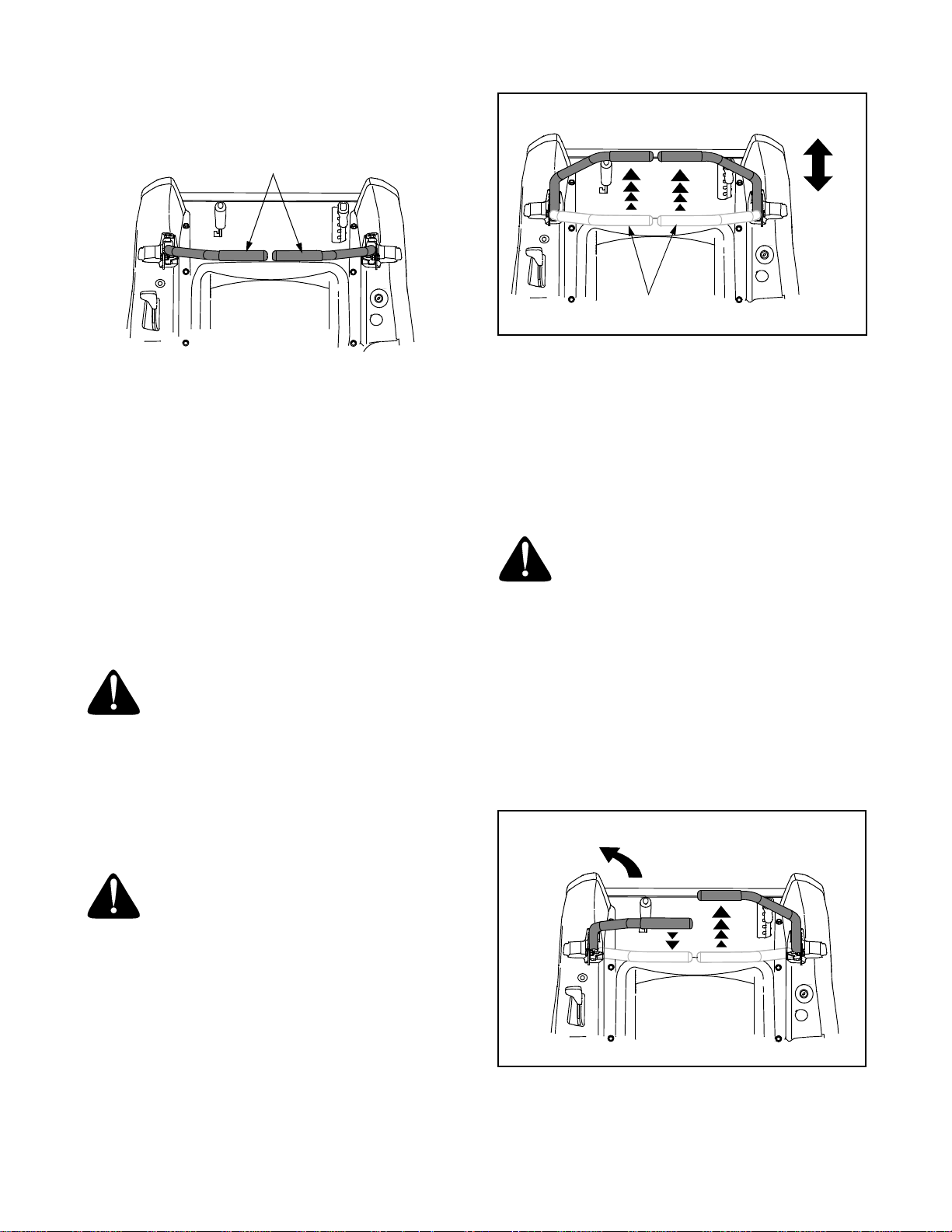
ADJUSTING RH & LH DRIVE CONTROL LEVERS
The RH and LH drive control levers can be adjusted
up or down and fore-and-aft for the comfort of the
operator. The drive control levers can be placed in
either of two height positions, or can be moved
forward or rearward within the range of the slot in
each control lever mounting bracket.
To adjust the drive control lever height, proceed as
follows:
• Remove the nut knob, bell washer, and carriage
bolt securing the lever to the pivot bracket.
• While supporting the control lever to keep it from
falling, remove the hex insert flange lock nut and
shoulder screw from the bottom of the control
lever and pivot bracket. Refer to Figure 20.
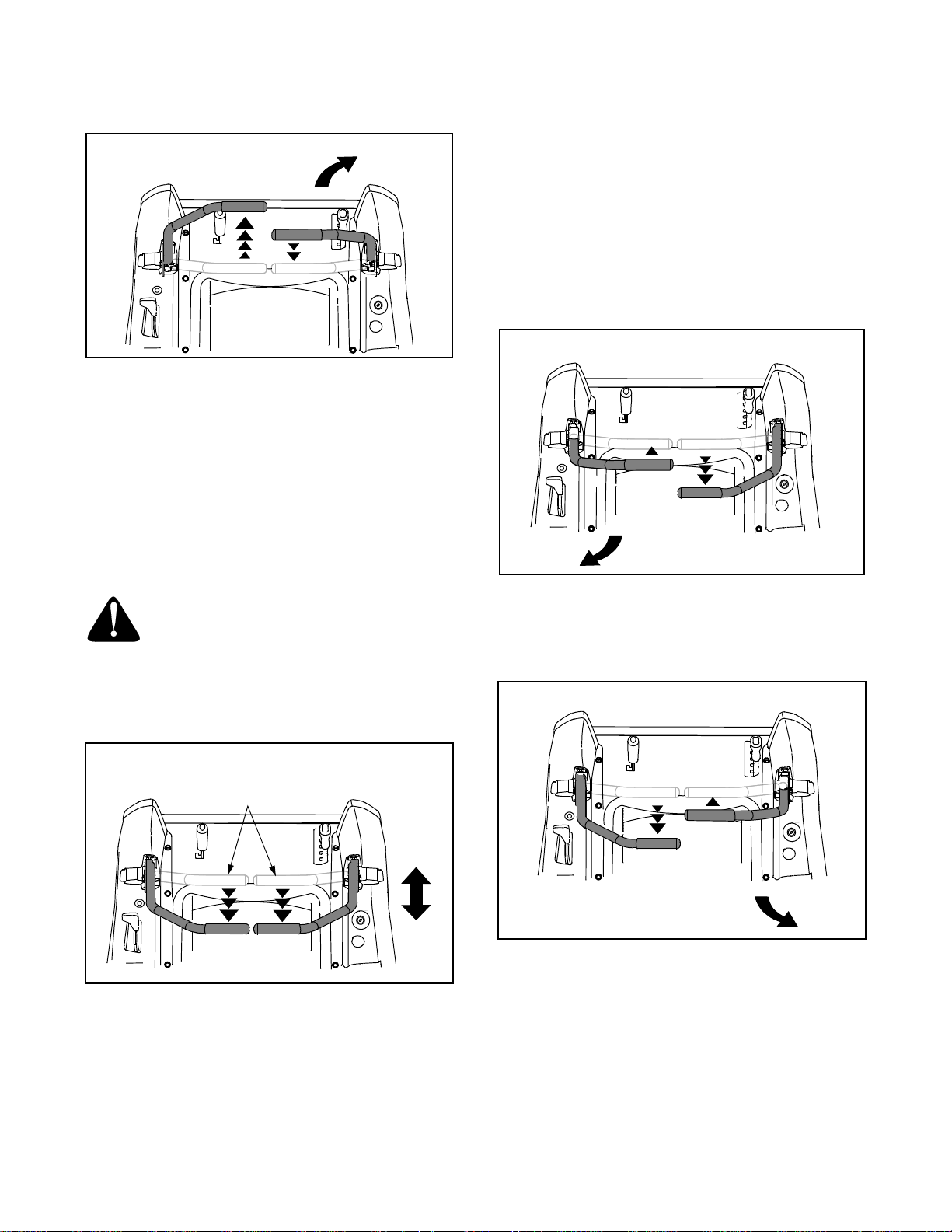
• Reposition the control lever to align with the other
set of holes in the pivot bracket and insert the
shoulder screw removed earlier. Fasten with the
hex insert flange lock nut and tighten until snug.
• Insert the hex screw w/washer through the
control lever slot and the pivot bracket.Thread the
flange lock nut onto the screw, but do not tighten
now.
• If you are going to adjust the control levers
forward or rearward, proceed to the next step. If
not, fully the flange lock nut.
Pivot Bracket
Flange
Lock Nut
Height
Adjust
Holes
Slot
Control Lever
Flat Washer
Hex Screw
Shoulder
Screw
Figure 20
To adjust the drive control levers forward or rearward,
proceed as follows:
If not already loose, loosen the flange lock nut and
rotate the control lever either forward or rearward to
the desired position. See Figure 20.
NOTE: If the control lever is too tight to move, slightly
loosen the hex insert flange lock nut and shoulder
screw at the bottom of the control lever.
• Tighten the flange lock nut to fix the control lever
in the adjusted position
• Repeat the above procedure to adjust the other
control lever into the same position. Adjust so
that both levers are even with each other when in
the neutral position.
21
Page 22
SECTION 4: MAINTENANCE
ENGINE MAINTENANCE
Engine maintenance procedures and schedules can
be found in the engine manual. Follow those instructions for performing engine maintenance.
Using the Engine Oil Drain Valve
• Run the engine for a short time to warm the
engine oil. The oil will flow more freely and carry
away more impurities Use care to avoid burns
from hot oil.
• Locate the oil drain hose on the RIGHT side of
the engine. Refer to Figure 21.
• Route the free end of the oil drain hose toward an
appropriate oil collection container with at least a
2.5 quart capacity, to collect the used oil.
Remove the oil fill cap/dipstick from the oil fill
tube.
• While holding the free end of the oil drain hose
over the oil collection container, unscrew the
square head hose plug from the end of the hose.
See Figure 21. Drain the engine oil into the
collection container.
• After draining the oil, wipe any residual oil from
the oil drain hose. Thread the square head plug
into the drain hose fitting and fully tighten the
plug.
• Replace the oil filter, and refill the engine with
new oil as instructed in the separate engine
manual.
Protective
Cap
GENERAL BATTERY INFORMATION
WARING
• Battery posts, terminals and related accessories
contain lead and lead compounds. Wash hands
after handling.
• Should battery acid accidentally splatter into the
eyes or onto the skin, rinse the affected area
immediately with clean cold water. If there is any
further discomfort, seek prompt medical attention.
• If acid spills on clothing, first dilute it with clean
water, then neutralize with a solution of ammonia/
water or baking soda/water.
• NEVER connect (or disconnect) battery charger
clips to the battery while the charger is turned on,
as it can cause sparks.
• Keep all sources of ignition (cigarettes, matches,
lighters) away from the battery. The hydrogen
gas generated during charging can be
combustible.
• As a further precaution, only charge the battery in
a well ventilated area.
• Always shield eyes and protect skin and clothing
when working near batteries.
WARNING: Batteries contain sulfuric
acid and may emit explosive gases. Use
extreme caution when handling batteries. Keep batteries out of the reach of
children.
BATTERY REMOVAL
Oil Drain
Hose
Turn and
Pull Out
Oil Drain
Valve
Figure 21
HYDROSTATIC TRANSMISSION MAINTENANCE
The zero turn tractor is equipped with dual integrated
hydrostatic pumps, motors, and transaxles that are
sealed and do not require regular maintenance. All
service work on the hydrostatic transmissions should
be performed by your dealer.
WARNING: Battery posts, terminals and
related accessories contain lead and
lead compounds. Wash hands after
handling.
The battery is located on the right/rear of the tractor
beneath the seat box frame.
To remove the battery:
• Remove the two hex tapping screws from the battery holddown bracket and remove the bracket.
Use care to avoid losing the trim strip from the
bottom of the bracket.
• Remove the hex cap screw and sems nut securing the black negative battery lead to the negative
battery post (marked NEG). Move the cable away
from the negative battery post.
• Remove the hex cap screw and sems nut securing the red positive battery lead to the positive
battery post (marked POS).
22
Page 23

• Carefully lift the battery out of the tractor.
Install the battery by repeating the above steps in the
reverse order.
WARNING: Always connect the positive
lead to the battery before connecting the
negative lead. This will prevent sparking
or possible injury from an electrical short
caused by contacting the tractor body
with tools being used to connect the
cables.
CHARGING THE BATTERY
Test and, if necessary, recharge the battery after the
tractor has been stored for a period of time.
• A voltmeter or load tester should read 12.6 volts
(DC) or higher across the battery terminals.
• Charge the battery with a 12-volt battery charger
at a MAXIMUM rate of 10 amps.
• Recharge the battery before returning to service.
Although the tractor may start, the engine charging
system may not fully recharge the battery.
SERVICING ELECTRICAL SYSTEM
A fuse is installed to protect the tractor’s electrical
system from damage caused by excessive amperage. Always use the same capacity fuse for
replacement. If the electrical system does not function, check for a blown fuse. See Figure 22
If you have a recurring problem with blown fuses,
have the tractor’s electrical system checked by your
dealer.
GOOD
BAD
Figure 22
Voltmeter
Reading
12.7 100% Full Charge
12.4 75% 90 Min.
12.2 50% 180 Min.
12.0 25% 280 Min.
State of
Charge
Charging
Time
BATTERY MAINTENANCE
The battery is filled with battery acid and then sealed
at the factory. However, even a “maintenance free”
battery requires some maintenance to ensure its
proper life cycle.
• Spray the terminals and exposed wire with a
battery terminal sealer, or coat the terminals with
a thin coat of grease or petroleum jelly, to protect
against corrosion.
• Always keep the battery cables and terminals
clean and free of corrosion.
• Avoid tipping. Even a sealed battery will leak
electrolyte when tipped.
BATTERY STORAGE
• When storing the tractor for extended periods,
disconnect the negative battery cable. It is not
necessary to remove the battery.
• All batteries discharge during storage. Keep the
exterior of the battery clean, especially the top. A
dirty battery will discharge more rapidly.
• The battery must be stored with a full charge. A
discharged battery can freeze sooner than a
charged battery. A fully charged battery will store
longer in cold temperatures than hot.
Relays and Switches
There are several safety switches in the electrical
system. If a function of the safety interlock system
described earlier is not functioning properly, have the
electrical system checked by your dealer.
LUBRICATION
• Using a pressure lubricating gun, lubricate the
front castor axles and pivot axle with a No. 2
multi-purpose grease after every 10 hours of
service.
• Refer to the "MOWER DECK" section later in this
manual for deck lubrication procedures.
• Periodically lubricate all other pivot points with a
quality lubricating oil.
TIRE MAINTENANCE
Check the tire air pressure after every 50 hours of
operation or weekly. Keep the tires inflated to the
recommended pressures. Improper inflation will
shorten the service life of a tire. See the tire side wall
for proper inflation pressures. Observe the following
guidelines:
• Do not inflate a tire above the maximum pressure
shown on the sidewall of the tire.
• Do not reinflate a tire that has been run flat or
seriously under inflated. Have a qualified tire
mechanic inspect and service the tire.
23
Page 24

USING THE TRANSMISSION BYPASS RODS
If for any reason the tractor will not drive or you wish
to move the tractor, the two hydrostatic transmissions are equipped with bypass rod that will allow you
to manually move the tractor short distances.
WARNING: Do not tow the tractor, even
with the bypass rod engaged. Serious
transmission damage will result from
doing so.
• From just in front of the two rear tires, locate the
transmission bypass rods. See Figure 23.
• Pull one rod toward the front of the tractor until
the flange on the rod is forward of the keyhole
slot in the frame assembly.
• Lower the bypass rod into the keyhole slot and
release so the rod flange is against the front of
the frame bracket.
• Repeat the above procedure to engage the other
bypass rod.
RH Transmission
Bypass Rod
Pull out
Bypass Rod
Then Lower
In Slot
TRACTOR CREEPING
Creeping is the slight forward or backward movement
of the tractor when the engine is running at high idle
and the drive control levers are opened out in the
neutral position.
If after operating the tractor for some time, it begins to
creep while in the neutral position, adjust the
transmission control rods as follows.
• Place the front of the tractor against an
immovable object (e.g. wall, post, etc.).
• Jack up the rear of the tractor so that both rear
wheels are approximately one inch of the ground.
• With the engine running at high idle and the drive
control levers opened out in the neutral position,
and the parking brake disengaged, check the rear
wheels for rotation.
• If only one wheel is rotating, locate the transmission control rod beneath the frame at the front of
the rear tire. If both wheels rotate, locate both
control rods. See Figure 24.
RH Transmission
Control Rod
Internal
Cotter Pin
Keyhole
Slot
Figure 23
• After moving the tractor, disengage both bypass
rods. Lift the rod and guide the flange of the rod
back through the larger circular opening of the
keyhole, then release the rod.
IMPORTANT: The tractor will not drive with the
bypass rods in the engage position.
Ferrule
Transmission
Control Arm
Figure 24
• Remove the internal cotter pin securing the
ferrule to the transmission control arm and
withdraw the ferrule. Wheel rotation should stop.
If it does not, contact your White Outdoor dealer.
• If the rotation stops, adjust the ferrule up or down
the control rod as necessary to align with the hole
in the transmission control arm. Re-insert the
ferrule into the hole in the control arm and secure
with the internal cotter pin.
• If necessary, repeat the previous two steps to
adjust the other transmission control rod.
• Lower the tractor and remove the jack.
24
Page 25

TRACTOR HIGH SPEED TRACKING
If the tractor tracks to one side with both drive control
levers fully forward, adjust the control levers as
follows:
• Check for proper and balanced air pressure in
both front and rear tires. Refill tires if necessary.
• Perform the first three steps in the previous subsection, Tractor Creeping, to verify that the tractor
is not creeping. If creeping, adjust following the
instructions in that sub-section.
• Recheck the tracking after making any adjustments to the transmission control rods.
• If uneven tracking persists, note which direction
the tractor is tracking.
- If the tractor tracks to the right, adjust the
control lever stop bolt on the left side.
- If the tractor tracks to the left, adjust the control
lever stop bolt on the right side.
• Locate the applicable stop bolt on the left or right
console. See Figure 25.
TRANSMISSION DRIVE BELT
If the transmission drive belt becomes worn and
causes the drive transmissions to slip, the drive belt
must be replaced. To replace the drive belt, proceed
as follows:
• Remove the deck drive belt from the PTO clutch
on the bottom of the engine following the instructions in Deck Removal, SECTION 5: MOWER
DECK.
• From beneath the rear of the tractor, insert a 3/8
inch drive ratchet into the square hole of the drive
idler bracket. See Figure 26.
Transmission
Drive Pulley
Idler
Pulley
Console
Jam Nut
Stop Bolt
Figure 25
• Loosen the jam nut on the stop bolt, then turn the
stop bolt counterclockwise to make it longer.
Recheck the tracking and fine tune the adjustment as necessary.
NOTE: If the stop bolt is adjusted too far, the
tracking problem will change sides. Make fine
tuning adjustments by shortening the same bolt.
• Tighten the jam nut against the console and reposition the control lever if necessary.
Square
Hole
Idler
Bracket
Idler Brkt.
Spring
Engine
Pulley
Drive
Belt
PTO
Pulley
Figure 26
• Using the ratchet for leverage, pivot the idler
bracket and idler pulley away from the backside
of the ‘V" belt; then lift the belt off and above the
engine pulley and off the idler pulley.
• With the belt loose, lift the belt off, up and over
the two transmission drive pulleys. Remove the
belt from the engine and idler pulleys.
• Loop the new belt and slide over and onto the
two transmission pulleys.
• Route the belt above the idler bracket back to the
engine drive pulley. Lift the belt over the PTO pulley and above the engine drive pulley.
• Using the ratchet for leverage, pivot the idler
bracket and idler pulley against the spring tension; then slip the belt down into the engine drive
pulley and onto the idler pulley.
• Release the idler bracket so that the idler pulley
tightens against the back side of the belt and tensions the drive belt.
• Reinstall the deck drive belt.
25
Page 26

TRACTOR STORAGE
If your tractor is not going to be operated for an
extended period of time (thirty days to approximately
six months), the tractor should be prepared for storage. Store the tractor in a dry and protected location.
If stored outside, cover the tractor (including the tires)
to protect it from the elements. The procedures outlined below should be performed whenever the tractor
is placed in storage.
1. Change the engine oil and filter following the
instructions provided in the engine information at
the back of this manual.
WARNING: Never store the tractor with
fuel in the tank indoors or in poorly ventilated enclosures, where fuel fumes may
reach an open flame, spark or pilot light
as on a furnace, water heater, clothes
dryer, etc.
WARNING: Fuel left in the fuel tank deteriorates and will cause serious starting
problems.
2. If storing the tractor for 30 days or more:
To prevent gum deposits from forming inside the
engine’s carburetor and causing possible malfunction of the engine, the fuel system must be either
completely emptied, or the gasoline must be
treated with a stabilizer to prevent deterioration.
Using a fuel stabilizer:
• Read the product manufacturer’s instructions
and recommendations.
• Add to clean, fresh gasoline the correct amount
of stabilizer for the capacity (approximately 3
gallons) of the fuel system.
• Fill the fuel tank with treated fuel and run the
engine for 2-3 minutes to get stabilized fuel into
the carburetor.
Emptying the fuel system:
• Prior to putting the tractor in storage, monitor
fuel consumption with the goal of running the
fuel tank empty.
• Run the engine until it begins to stall. Use the
choke to keep the engine running until all fuel in
the carburetor has been exhausted.
3. Clean the engine and the entire tractor
thoroughly.
4. Fully charge the battery, then disconnect the negative cable at the battery to prevent possible
discharge. Recharge the battery periodically
when in storage.
NOTE: Remove the battery if exposed to prolonged
periods of sub-freezing temperatures. Store in a cool,
dry location where temperatures are above freezing.
5. Lubricate all lubrication points.
NOTE: We do not recommend the use of a pressure
washer or garden hose to clean your unit. They may
cause damage to electrical components; spindles;
pulleys; bearings; or the engine. The use of water will
result in shortened life and reduce serviceability.
REMOVING THE TRACTOR FROM STORAGE
• Check the engine oil.
• Fully charge the battery and inflate the tires to the
recommended pressure.
• Add clean, fresh fuel.
• Start the engine and allow to idle for a few
minutes to ensure engine is operating properly.
• Drive the tractor without a load to make certain all
the tractor systems are functioning properly.
26
Page 27

SECTION 5: MOWER DECK
This section contains removal, installation, adjustment, and maintenance information for the 42-inch
(ZT42) and 50-inch (ZT50) mower decks.
DECK REMOVAL
Remove the mower deck from the tractor as follows:
1. Move the tractor to a level surface, disengage the
PTO, stop the engine, and set the parking brake.
2. Move the deck gauge wheels to their highest
setting (lowest deck setting).
3. Remove the ‘V’ belt from the PTO pulley, located
on the bottom of the engine, using one of the
following two methods.
Releasing belt tension with the idler pulley.
• Using the deck lift handle, raise the deck to the
upper position that allows for the most horizontal
run of the belt between the deck idler pulleys and
the PTO pulley on the bottom of the engine.
• Working from the middle of the tractor, pivot the
idler bracket and movable idler pulley rearward
away from the backside of the ‘V" belt just far
enough to lift the belt up and over the idler pulley.
See Figure 27.
42 INCH DECK SHOWN
Pull Idler Pulley
Rearward
Movable Idler
Pulley
Rolling the belt off the PTO pulley.
• Using the deck lift handle, raise the deck to the
upper position that allows for the most horizontal
run of the belt between the deck idler pulleys and
the PTO pulley on the bottom of the engine.
WARNING: The muffler at the rear of the
tractor may be extremely hot, and could
cause serious burns. Use extreme
caution when near the muffler, or allow
the muffler to fully cool before removing
the belt.
• Sitting behind the tractor facing forward, reach
beneath the tractor to grasp the belt at the front of
the PTO pulley.
WARNING: Use caution to prevent
pinching your fingers when rolling the
belt off the PTO pulley.
• Pull the left side of the belt rearward and downward while manually turning the PTO pulley to the
right until the belt rides out onto the edge of the
lower sheave of the pulley. NOTE: If pulling the
right side of the belt, turn the pulley to the left.
• While still holding the belt downward, continue
turning the PTO pulley until the belt is rolled off
the pulley.
4. Lower the deck to the ground using the deck lift
handle.
• Locate the LH and RH deck support pins on each
side of the deck. Pull the deck support pins
outward and lock in the disengaged position to
release the deck from the tractor’s LH and RH
deck lift arms. See Figure 28.
Fixed Idler
Pulley
‘V’ Belt
Idler Bracket
Figure 27
WARNING: The muffler at the rear of the
tractor may be extremely hot, and could
cause serious burns. Use extreme
caution when near the muffler, or allow
the muffler to fully cool before removing
the belt.
• From beneath the rear of the tractor, slide the belt
off of the PTO pulley on the bottom of the engine.
Rear Deck
Hanger Bracket
Deck
Support
Pin
Deck Lift Arm
Rear Hanger
Bracket Slot
Figure 28
• Raise the deck lift arms out of the rear hanger
bracket slots by raising the deck lift handle on the
tractor to its highest position.
27
Page 28

• Slide the deck forward so that the deck front
hanger rod can be lifted out of the two slots of the
front deck bracket. After lifting the front hanger
rod out of the slots, slide the deck rearward so
that the rod can no longer engage the slots.
• Using care to prevent the front hanger rod from
falling back into the deck slots, gently slide the
cutting deck (from the right side) out from
underneath the tractor.
DECK INSTALLATION
To install the mower deck, proceed as follows:
1. While holding up the deck front hanger rod,
carefully slide the deck underneath the right side
of the tractor.
2. While still holding the front hanger rod, slide the
deck forward until the front hanger rod can be
lowered into the slots at the front of the deck.
3. Lower the front hanger rod into the slots of the
front deck bracket, then slide the deck rearward.
4. Maneuver the deck so that the slots in the two
rear deck hanger brackets approximately align
with the deck lift arms of the tractor. Refer to
Figure 28.
5. Use the deck lift handle of the tractor to lower the
deck lift arms into the slots of the rear deck
hanger brackets.
6. Pull the deck support pins outward and maneuver
the deck as necessary to align the holes in the
deck lift arm with the pins. Refer to Figure 28.
7. When aligned, push each pin fully inward through
the lift arms to secure the arms in the rear hanger
bracket slots.
8. Make certain the ‘V’ belt is in the spindle pulleys
on the deck, then route the belt rearward beneath
the tractor frame and above the two transmission
tubes
9. Install the ‘V’ belt onto the PTO pulley using one
of the following two methods.
Using the idler pulley to tension the belt.
• Using the deck lift handle, raise the deck to the
upper position that allows for the most horizontal
run of the belt between the deck idler pulleys and
the PTO pulley on the bottom of the engine.
WARNING: The muffler at the rear of the
tractor may be extremely hot, and could
cause serious burns. Use extreme
caution when near the muffler, or allow
the muffler to fully cool before removing
the belt.
• Install the belt in the PTO pulley on the bottom of
the engine.
• Route the backside of the belt around the fixed
idler pulley of the deck. Refer to Figure 27.
• Working from the middle of the tractor, pivot the
idler bracket/movable pulley rearward against the
spring tension and slide the backside of the belt
onto the movable idler pulley. Refer to Figure 27.
Rolling the belt into the PTO pulley.
• Using the deck lift handle, raise the deck to the
upper position that allows for the most horizontal
run of the belt between the deck idler pulleys and
the PTO pulley on the bottom of the engine.
• Make certain the belt is in the spindle pulleys of
the deck, and that the backside of the belt is
against both the fixed and movable idler pulleys.
Refer to Figure 27.
WARNING: The muffler at the rear of the
tractor may be extremely hot, and could
cause serious burns. Use extreme
caution when near the muffler, or allow
the muffler to fully cool before removing
the belt.
• Sitting behind the tractor, facing forward, make
certain the belt is not twisted; then reach beneath
the tractor to grasp the belt and pull it toward the
PTO pulley.
WARNING: Use caution to prevent
pinching your fingers when rolling the
belt off the PTO pulley.
• Pull the right side of the belt rearward and place
the narrow V side of the belt into the right/front
side of the PTO pulley. See Figure 29.
• While holding the belt and pulley together, rotate
the pulley to the left (See Figure 29). Continue
holding and rotating the pulley and belt until the
belt is fully rolled into the PTO pulley. NOTE: If
using the left side of the belt, turn the pulley to
the right.
PTO Pulley
PTO Belt
Rotate
Pulley
Transmission
Tube
Figure 29
28
Page 29

LEVELING THE MOWER DECK
When leveled correctly the mower deck should be
level side to side, and should be approximately a 1/8
to 1/4 inch lower in the front of the deck.
Side to Side Leveling
If the cutting deck appears to be mowing unevenly, a
side to side adjustment can be performed. Adjust if
necessary as follows:
• With the tractor parked on a firm, level surface,
place the deck lift handle in the top notch (highest
position) and rotate both blades so that they are
perpendicular to the tractor frame.
• Measure the distance from the outside left blade
tip to the ground and the distance from the
outside right blade tip to the ground. The
measurements should be equal. If they’re not,
proceed to the next step.
• Compare the two measurements as follows:
- Model ZT42—determine whether the right side
of the deck must be raised or lowered.
- Model ZT50—determine whether the left side
of the deck must be raised or lowered.
• ZT42 - 42 Inch Deck ONLY
- Loosen, but do not remove, the hex cap screw
on the right deck hanger bracket. Refer to
Figure 30.
- Level the deck by using a wrench to turn the
adjustment gear (found immediately behind the
hex cap screw just loosened) clockwise to
lower the right side of the deck, or
counterclockwise to raise the right side of the
deck. Refer to Figure 30.
- The deck is properly leveled when both blade
tip measurements taken earlier are equal.
Raise RT.
Side of Deck
Adjustment
Gear
Lower RT.
Side of Deck
Hex Cap
Screw
Figure 30
- Retighten the hex cap screw on the right deck
hanger bracket when proper adjustment is
achieved.
• ZT50 - 50 Inch Deck ONLY
- Loosen, but do not remove, the hex cap screw
on the left deck hanger bracket. Refer to Figure
31.
- Level the deck by using a wrench to turn the
adjustment gear (found immediately behind the
hex cap screw just loosened) clockwise to raise
the left side of the deck, or counterclockwise to
lower the left side of the deck.
Lower LT.
Side of Deck
Adjustment
Gear
Raise LT.
Side of Deck
Hex Cap
Screw
Figure 31
- The deck is properly leveled when both blade
tip measurements taken earlier are equal.
- Retighten the hex cap screw on the left deck
hanger bracket when proper adjustment is
achieved.
Front to Back Leveling.
The front of the deck should be approximately 1/8 to
1/4 inch lower than the rear of the deck. Adjust if necessary as follows:
• With the deck raised off of the ground, rotate the
blades so that they are parallel to the frame of the
tractor.
• If the side to side leveling was done correctly,
measuring just the right blade should be
acceptable to attain the correct back to front pitch
of the deck.
• Measure the distance from the front tip of the
blade to the ground and the distance from the
rear tip to the ground. The front distance should
be 1/8 to 1/4 inch less than the rear. If it is not,
proceed to the next step.
29
Page 30

• From the front of the tractor, loosen the outer
nuts on the deck front hanger rod, and turn them
away from the inner nuts. See Figure 32.
Hex Nuts
• With the deck set at the desired height, check the
distance between the gauge wheels and the
ground. If the gauge wheels are near or touching
the ground, they should be raised. If the gauge
wheels are too high, they should be lowered.
• Remove the lock nut securing one of the gauge
wheel shoulder screws to the deck. Remove the
gauge wheel and shoulder screw. See Figure 33.
Front Hanger
Rod Bracket
Front
Hanger
Rod
Figure 32
• If the front of the deck was too low, turn the inner
hex nuts clockwise against the hanger bracket to
shorten the front hanger rod and raise the front of
the deck. See Figure 32.
• If the front of the deck was too high, turn the hex
nuts counterclockwise to lengthen the front
hanger rod and lower the front of the deck.
IMPORTANT: The deck front hanger rod should
be at the front of the slots of the front deck
bracket. If one side of the rod is not at the front of
its slot, turn the inner hex nut on that side until
rod just touches the front of the slot. Then remeasure and re-adjust the front hanger rod as
necessary.
• When the correct pitch of the deck is acquired,
secure the inner hex nuts with a wrench and
tighten the outer hex nuts against the inner hex
nuts to lock them in the adjusted position.
ADJUSTING THE GAUGE WHEELS
The cutting height of the mower deck can be set in
any of six height settings using the deck lift handle of
the tractor. The deck heights range from 1-1/2 inches
to 4 inches. The deck gauge wheel position should be
approximately 1/4 to 1/2 inch above the ground when
the deck is set in the desired height setting.
WARNING: Keep hands and feet away
from the discharge opening of the
cutting deck.
NOTE: The deck gauge wheels are an anti-scalp
feature of the deck and are not designed to support the
weight of the cutting deck.
Using the lift handle, set the deck in the desired
height setting, then check the gauge wheel and if
necessary adjust as follows:
42 INCH DECK
Shoulder
Screw
50 INCH DECK
Shoulder
Screw
Rear Gauge
Wheel
Rear Gauge
Wheel
Gauge
Wheel
Bracket
Lock
Nut
Adjustment
Index
Holes
Lock
Nut
Gauge
Wheel
Bracket
Deck Adjustment
Index Holes
Shoulder
Screw
Front Gauge
Wheel
Gauge
Wheel
Bracket
Lock
Nut
Figure 33
• Insert the shoulder screw in the one of four index
holes that will give the gauge wheel a 1/4 to 1/2
inch clearance with the ground.
• Note the index hole of the just adjusted wheel,
and adjust the other gauge wheels into the
respective index holes on the other gauge wheel
brackets on the deck.
DECK MAINTENANCE
Using the Deck Wash System
WARNING: When using the deck wash
system, never engage the deck from any
position other than the operator’s seat of
the tractor. Do not use an assistant or
engage deck in the presence of any
bystanders.
• Attach the nozzle adapter to a standard garden
hose connected to a water supply.
• Move the tractor to an area within reach of the
hose where the dispersal of wet grass clippings is
not objectionable to you. Disengage the PTO,
engage the parking brake, and stop the engine.
30
Page 31

• Pull back the lock collar of the nozzle adapter and
push the adapter onto the deck wash nozzle at
the left end of the 42" mower deck, or onto one of
the deck wash nozzles at either end of the 50"
mower deck. Release the lock collar to lock the
adapter on the nozzle. See Figure 34.
42 INCH DECK SHOWN
Nozzle
Adapter
Adapter
Lock Collar
Pull Lock
Collar Back
Deck Wash
Nozzle
Figure 34
The cutting blades must be kept sharp at all times.
Sharpen the cutting edges of the blades evenly so
that the blades remain balanced and the same angle
of sharpness is maintained.
If the cutting edge of a blade has already been sharpened many times, or if any metal separation is present,
it is recommended that new blades be installed. New
blades are available at your authorized dealer.
The blades may be removed as follows.
• Remove the deck from beneath the tractor, (refer
to Deck Removal on page 28) then gently flip the
deck over to expose its underside.
• Use a 15/16 inch wrench to hold the hex nut on
top of the spindle assembly when loosening the
hex nut securing the blade. A block of wood may
be placed between the deck housing and the cutting edge of the blade to help in breaking loose
the hex nut securing the blade. See Figure 35.
• Turn on the water supply.
• From the tractor operator’s seat, start the engine
and engage the PTO. Allow to run as needed.
Disengage the PTO and stop the engine.
• Turn off the water supply.
• Pull back the lock collar of the nozzle adapter to
disconnect the adapter from the nozzle.
• 50" Deck ONLY - Repeat the previous steps to
clean the deck using the nozzle at the other end
of the deck.
Cleaning the Spindle Pulleys
Once a month remove any accumulation of grass
clippings from around the spindle pulleys and V-belt.
Clean more often when mowing tall, dry grass.
Mower Blade Care
WARNING: Before performing any maintenance, place the PTO switch in the
“OFF” position, engage the parking
brake lever, turn the ignition key to the
“OFF” position and remove the key from
the switch. When servicing the mower
deck, be careful not to cut yourself on
the sharpened blades.
HEX FLANGE NUT
WOOD
BLOCK
SPINDLE ASSEMBLY
Figure 35
• When reinstalling the blades, be sure they are
installed so that the wind wings are pointing
upward toward the top of the deck.
• Reinstall the deck (refer to Deck Installation on
page 29).
31
Page 32

DECK LUBRICATION
• After every 10 hours of operation and/or before
putting the deck into winter storage, lubricate
the spindle assemblies with a No. 2
multipurpose lithium grease. The lube fittings
are located in the spindle housing and can be
accessed from underneath the deck.
42 INCH MOWER DECK
REPLACING THE DECK DRIVE BELT
• Remove the deck from beneath the tractor, (refer
to Deck Removal on page 28).
• Remove the hex tapping screws securing the belt
covers to the deck and remove the belt from the
spindle pulleys. Refer to Figure 36.
• Depending on which deck (42" or 50") you are
working on, install the new belt around the
spindle pulleys as shown in the applicable
graphic of Figure 36. Reinstall the belt covers.
• Route the belt rearward between the two idler
pulleys and reinstall the deck following the
instructions in Deck Installation on page 29.
Belt Cover
Belt Cover
Idler Pulley
Belt Cover
‘V’ Belt
Idler Pulley
50 INCH MOWER DECK
‘V’ Belt
Belt Cover
Idler Pulley
Idler Pulley
Figure 36
32
Page 33

SECTION 6: TROUBLE SHOOTING
Problem Cause Remedy
Engine fails to start PTO/Blade Engage knob engaged.
Engine runs erratic Unit running with CHOKE activated.
Engine overheats Engine oil level low.
Engine hesitates at high
RPM
Engine Idles rough Spark plug(s) fouled, faulty or gap too wide.
Excessive vibration Cutting blade loose or unbalanced.
Uneven cut Deck not leveled properly.
Mower will not mulch grass
(If Equipped w/Mulching
Kit)
1.
Parking brake not engaged.
2.
Drive control levers not fully outward in
3.
neutral position.
Spark plug wire(s) disconnected.
4.
Throttle control lever not in correct starting
5.
position.
Choke not activated
6.
Fuel tank empty, or stale fuel.
7.
Blocked fuel line.
8.
Faulty spark plug(s).
9.
Engine flooded.
10.
1.
Spark plug wire(s) loose.
2.
Blocked fuel line or stale fuel.
3.
Vent in gas cap plugged.
4.
Water or dirt in fuel system.
5.
Dirty air cleaner.
6.
1.
Air flow restricted.
2.
Spark plug(s) gap too close. 1. Remove spark plug(s) and reset the gap. 1.
1.
Dirty air cleaner.
2.
1.
Damaged or bent cutting blade.
2.
1.
Dull blade.
2.
Uneven tire pressure.
3.
Engine speed too low.
1.
Wet grass.
2.
Excessively high grass.
3.
Dull blade.
4.
Place knob in disengaged (OFF) position.
1.
Engage parking brake.
2.
Move drive control levers fully outward in
3.
neutral position.
Connect wire(s) to spark plug(s).
4.
Place throttle lever to FAST position.
5.
Pull the CHOKE control outward.
6.
Fill tank with clean, fresh (less than 30 days
7.
old) gas.
Clean fuel line and replace fuel filter.
8.
Clean, adjust gap or replace plug(s).
9.
Crank engine with throttle in FAST position.
10.
Push CHOKE control in.
1.
Connect spark plug wire(s).
2.
Clean fuel line; fill tank with clean, fresh
3.
gasoline and replace fuel filter.
Clear vent or replace cap if damaged.
4.
Drain fuel tank. Refill with clean, fresh
5.
gasoline.
Replace air cleaner paper element or clean
6.
foam precleaner.
Fill crankcase with proper amount and
1.
weight of oil.
Clean grass clippings and debris from around
2.
the engine’s cooling fins and blower housing.
Replace spark plug(s). Set plug gap.
1.
Replace air cleaner element and/or clean
2.
pre-cleaner.
Tighten blade and spindle.
1.
Replace blade.
2.
Perform side-to-side deck adjustment.
1.
Sharpen or replace blade.
2.
Check tire pressure in all four tires.
3.
Place throttle in FAST (rabbit) position.
1.
Do not mulch when grass is wet.
2.
Mow once at a high cutting height, then
3.
mow again at desired height or make a
narrower cutting swath.
Sharpen or replace blade.
4.
33
Page 34

SECTION 7: REPLACEMENT PARTS
NOTE: Download a complete Parts Manual free of charge at www.mtdcanada.ca or phone (800) 668-1238
to purchase a Parts Manual. Be sure to have your model number and serial number ready. These can be
found on the model plate located under the seat.
This Operators Manual covers a range of product specifications for various models. Characteristics and
features discussed and/or illustrated in this manual may not be applicable to all models. MTD LLC reserves
the right to change product specifications, designs and equipment without notice and without incurring
obligation.
RZT Series Tractor
Drive Belt (Transmission) 754-04043A
Drive Belt (Mowing Deck) 42” Deck 754-04137
Drive Belt (Mowing Deck) 50” Deck 754-04044A
Deck Blade (42” Deck) two each 742-0616A
Deck Blade (50” Deck) three each 742-04053C
Deck Spindle (42” Deck) two each 618-0624
Deck Spindle (50” Deck) (three ea.) 618-04125A
Deck Wheel (four each) 734-04155
Battery 925-1707D
Caster Wheel Assembly 634-04321A
Tire (Rear) 18” x 8.5 x 8” Square Shoulder 734-04246
Tire (Rear) 20” x 9.5” x 8” Square Shoulder 734-1729
Fuel Tank Cap (Kawasaki) 751-10703
Fuel Tank Cap (Tecumseh) 751-3124D
Choke Control Cable (Kawasaki) 746-04214
Throttle Control Cable (Kawasaki) 746-04066
Throttle Control Cable (Tecumseh) 746-04161
WARNING: If a safety feature is not functioning properly, do not use the tractor.
Contact your authorized ervice dealer or call (800) 668-1238.
34
Page 35

CUB CADET LLC
MANUFACTURER’S LIMITED WARRANTY FOR
residential zero-turn (“rzt”) mowers
IMPORTANT: To obtain warranty coverage owner must present an
original proof of purchase and applicable maintenance records to the
servicing dealer. Please see the operator’s manual for information on
required maintenance and service intervals.
The limited warranty set forth below is given by Cub Cadet LLC with
respect to new merchandise purchased or leased and used in the
United States and/or its territories and possessions, and by MTD
Products Limited with respect to new merchandise purchased or leased
and used in Canada and/or its territories and possessions (either entity
respectively, “Cub Cadet”).
Cub Cadet warrants this product (excluding its Normal Wear Parts,
and Batteries as described below) against defects in material and
workmanship for a period of three (3) years commencing on the date
of original retail purchase or lease and will, at its option, repair or
replace, free of charge, any part found to be defective in materials or
workmanship.
Normal Wear Parts are warranted to be free from defects in material and
workmanship for a period of thirty (30) days from the date of original
purchase or lease. Normal wear parts include, but are not limited to
items such as: belts, blades, blade adapters, grass bags, rider deck
wheels, seats, and tires.
Batteries have a one-year prorated limited warranty against defects in
material and workmanship, with 100% replacement during the first three
months. After three months, the battery replacement credit is based on
the months remaining in the twelve (12) month period dating back to the
original date of original sale or lease. Any replacement battery will be
warranted only for the remainder of the original warranty period.
This limited warranty shall only apply if this product has been operated
and maintained in accordance with the Operator’s Manual furnished
with the product, and has not been subject to misuse, abuse, neglect,
accident, improper maintenance, alteration, vandalism, theft, fire, water,
or damage because of other peril or natural disaster. Damage resulting
from the installation or use of any part, accessory or attachment not
approved by Cub Cadet for use with the product(s) covered by this
manual will void your warranty as to any resulting damage. In addition,
Cub Cadet may deny warranty coverage if the hour meter, or any part
thereof, is altered, modified, disconnected or otherwise tampered with.
HOW TO OBTAIN SERVICE: Warranty service is available, WITH
PROOF OF PURCHASE AND APPLICABLE MAINTENANCE
RECORDS, through your local authorized service dealer. To locate the
dealer in your area:
In the U.S.A.:
Check your Yellow Pages, or contact Cub Cadet LLC at P.O. Box
361131, Cleveland, Ohio 44136-0019, call 1-877-282- 8684
or log on to our website at www.cubcadet.com.
In Canada:
Contact MTD Products Limited, Kitchener, ON N2G 4J1, call 1-800668-1238 or log on to our website at www.mtdcanada.com.
Without limiting the foregoing, this limited warranty does not provide
coverage in the following cases:
a. Routine maintenance items such as lubricants, filters, blade
sharpening, tune-ups, brake adjustments, clutch adjustments, deck
adjustments, and normal deterioration of the exterior finish due to
use or exposure.
b. Service completed by someone other than an authorized service
dealer.
c. Cub Cadet does not extend any warranty for products sold or
exported outside of the United States and/or Canada, and their
respective possessions and territories, except those sold through
Cub Cadet’s authorized channels of export distribution.
d. Replacement parts and\or accessories that are not genuine Cub
Cadet parts.
e. Transportation charges and service calls.
There are no implied warranties, including without limitation any
implied warranty of merchantability or fitness for a particular
purpose. No warranties shall apply after the applicable period
of express written warranty above. No other express warranties
beyond those mentioned above, given by any person or entity,
including a dealer or retailer, with respect to any product, shall
bind Cub Cadet. The exclusive remedy is repair or replacement of
the product as set forth above. The terms of this warranty provide
the sole and exclusive remedy arising from the sale and/or lease
of the products covered hereby. Cub Cadet shall not be liable for
any incidental or consequential loss or damage including, without
limitation, expenses incurred for substitute or replacement lawn
care services or for rental expenses to temporarily replace a
warranted product.
Some jurisdictions do not allow the exclusion or limitation of incidental
or consequential damages, or limitations on how long an implied
warranty lasts, so the above exclusions or limitations may not apply to
you.
In no event shall recovery of any kind be greater than the amount of the
purchase price of the product sold. Alteration of safety features of
the product shall void this warranty. You assume the risk and liability
for loss, damage, or injury to you and your property and /or to others and
their property arising out of the misuse or inability to use the product.
This limited warranty shall not extend to anyone other than the original
purchaser or to the person for whom it was purchased as a gift.
HOW LOCAL LAWS RELATE TO THIS WARRANTY: This limited
warranty gives you specific legal rights, and you may also have other
rights that vary in different jurisdictions.
4.10.08
Cub Cadet LLC, P.O. BOX 361131 CLEVELAND, OHIO 44136-0019, Phone: 1-877-282-8684
MTD Products Limited, Kitchener, ON N2G 4J1, Phone: 1-800-668-1238
Page 36

MTD Products Limited, Kitchener, ON N2G 4J1, téléphone: 1-800-668-1238
Cub Cadet LLC, P.O. BOX 361131 CLEVELAND, OHIO 44136-0019, téléphone: 1-877-282-8684
4.10.08
mtdcanada.com
la garantie.
IMPORTANT : Le propriétaire doit présenter le reçu original pour faire honorer
droits qui varient selon les juridictions.
accorde des droits juridiques spécifiques et vous pouvez bénéficier d’autres
LES LOIS LOCALES ET CETTE GARANTIE : Cette garantie limitée vous
laquelle le produit a été offert en cadeau.
Cette garantie limitée n’est offerte qu’à l’acheteur initial ou à la personne à
ou de l’incapacité de l’employer.
dommage matériel ou de blessure résultant de l’utilisation incorrecte du produit
L’utilisateur assume tout risque et toute responsabilité en cas de perte, de
des caractéristiques de sécurité rendra la garantie nulle et non avenue.
supérieur au montant du prix d’achat du produit vendu. Toute modification
Le remboursement ou remplacement quel qu’il soit ne sera en aucun cas
dans votre situation.
tacite. Par conséquent, les exclusions ci-dessus peuvent ne pas s’appliquer
dommages accessoires ou immatériels ou une limite à la durée de la garantie
Certaines juridictions ne permettent pas l’inclusion ou la restriction des
garantie.
ou les frais de location pour remplacer temporairement un produit sous
remplacement ou de substitution des services d’entretien des pelouse
accessoire ou immatériel comprenant, sans s’y limiter, les frais de
Cadet ne peut être tenue responsable pour toute perte ou tout dommage
vente ou de la location-bail des produits couverts par cette garantie. Cub
énoncées dans cette garantie offrent le seul recours à la suite de la
le recours unique et exclusif à la disposition du client. Les stipulations
ou le remplacement du produit dans les conditions ci-dessus constitue
concessionnaire /revendeur, pour n’importe quel produit. La réparation
Cadet même si elle est offerte par toute personne ou entité, y compris un
garantie expresse, à l’exception des stipulations ci-dessus, n’engage Cub
applicable de la garantie écrite expresse ci-dessus. Aucune autre
particulier. Aucune garantie ne s’applique après la période de vigueur
garantie tacite de qualité marchande ou d’adaptabilité dans un but
Aucune garantie tacite ne s’applique, y compris sans s’y limiter, toute
e. Les frais de transport des machines et de déplacement des techniciens.
authentiques.
d. Les pièces de rechange si elles ne sont pas des pièces Cub Cadet
de Cub Cadet.
ces produits ont été vendus par l’intermédiaire des services d’exportation
Unis et/ou du Canada, de leurs possessions et territoires respectifs, sauf si
c. Cub Cadet ne garantit pas les produits vendus ou exportés hors des États-
technique agréée.
b. L’entretien ou les réparations effectués par quiconque autre qu’une station
machine ou de son exposition aux intempéries.
coupe et la détérioration normale de la finition du fait de l’utilisation de la
lame et révisions, les réglages de frein, de l’embrayage ou du plateau de
a. Les articles d’entretien courant tels que les lubrifiants, filtres, aiguisages de
Sans se limiter à ce qui précède, cette garantie ne couvre pas :
N2G 4J1 ou appelez le 1-800-668-1238 ou visitez notre site web au www.
Au Canada : Adressez-vous à MTD Products Limited, Kitchener, Ontario,
8684. Vous pouvez aussi visiter notre site web au www.cubcadet.com
LLC, P.O. Box 361131, Cleveland, Ohio 44136-0019 ou appelez le 1-877-282Aux États-Unis : Consultez les Pages Jaunes ou adressez-vous à Cub Cadet
concessionnaire dans votre région :
agréée de votre localité. Pour localiser une station technique agréée ou un
ET LES RELEVÉS D’ENTRETIEN CORRESPONDANTS, à la station technique
POUR FAIRE HONORER LA GARANTIE : Présentez UNE PREUVE D’ACHAT
a été débranché ou altéré d’une façon quelconque.
pièce du compteur d’heures, a fait l’objet d’un changement, d’une modification,
peut en outre refuser d’honorer la garantie si le compteur d’heures, ou toute
pas homologué par MTD, rendront la garantie nulle et non avenue. Cub Cadet
annexe, dont l’emploi avec le produit faisant l’objet de la notice d’utilisation n’est
l’installation ou l’utilisation d’une pièce, d’un accessoire ou d’un équipement
autre dégât causé par tout incident ou désastre naturel. Les dégâts causés par
d’un acte de vandalisme, d’un vol, d’un incendie, d’une inondation ou de tout
d’une négligence, d’un accident, d’un entretien incorrect, d’une modification,
plus, le produit ne doit pas avoir fait l’objet d’un emploi incorrect ou abusif,
conformément aux instructions de la notice d’utilisation qui l’accompagne. De
Cette garantie limitée n’est applicable que si ce produit a été utilisé et entretenu
solde de la période de la garantie initiale.
l’achat ou de la location-bail. La batterie de remplacement est garantie pour le
la période de garantie de douze (12) mois à compter de la date initiale de
le crédit de remplacement sera proportionnel au nombre de mois restant dans
remplacées gratuitement pendant les trois premiers mois. Après cette période,
matière et de fabrication pour une durée proportionnelle d’un an et elles seront
Les batteries sont couvertes par une garantie limitée contre tout vice de
lames de raclage, le caoutchouc de la tarière et pneus.
roues du plateau de coupe, sièges, patins de souffleuses, roues de frottement,
s’y limiter, les batteries, courroies, lames, adaptateurs de lame, sacs à herbe,
date d’achat. Les pièces et composants à usure normale comprennent, sans
vice de matière et de fabrication pour une période de 30 jours à compter de la
Les pièces ou composants à usure normale sont garantis exempts de tout
pièce qui s’avère défectueuse en raison d’un vice de matière ou de fabrication.
initial et s’engage à réparer ou à remplacer, gratuitement et à son choix, toute
de fabrication pour une durée de trois (3) ans à compter de la date de l’achat
énumérées ci-dessous et des batteries) est exempt de tout vice de matière et
Cub Cadet garantit que ce produit (à l’exception des pièces à usure normale
l’autre entité respectivement appelée « Cub Cadet »).
les marchandises achetées et utilisées au Canada et/ou ses territoires (l’une ou
dans ses possessions et territoires, et par MTD Products Limited, pour toutes
pour toutes les marchandises neuves achetées et utilisées aux États-Unis,
La garantie limitée qui est énoncée ci-dessous est offerte par Cub Cadet LLC
tondeuse.
et intervalles des entretiens requis se trouvent dans la notice d’utilisation de la
tondeuse à la station technique. Les renseignements concernant les opérations
une preuve originale de l’achat et les relevés d’entretien correspondant à la
IMPORTANT : Pour faire honorer la garantie, le propriétaire doit présenter
(« RZT »)POUR UNE UTILISATION À DES FINS RÉSIDENTIELLES
GARANTIE LIMITÉE DU FABRICANT DES TONDEUSES À RAYON DE BRAQUAGE ZÉRO
CUB CADET LLC
Page 37

36
ou appelez 1-800-668-1238.
tionne pas correctement. Entrez en contact avec votre station technique agréée
AVERTISSEMENT: N’utilisez pas le tracteur si un dispositif de sécurité ne fonc-
Câble de commande de l’obturateur (Tecumseh) 746-04161
Câble de commande de l’obturateur (Kawasaki) 746-04066
Câble de volet de départ (Kawasaki) 746-04214
Capuchon d’essence (Tecumseh) 751-3124D
Capuchon d’essence (Kawasaki) 751-10703
Pneu (Arrière) 20,0 po x 9,5 po x 8,0 po” Épaulement carré 734-1729
Pneu (Arrière) 18,0 po x 8,5 po x 8,0 po” Épaulement carré 734-04246
Roulette pivotante 634-04321A
Batterie 925-1707D
Roues du plateau de coupe quadre requises 734-04155
Fusée (Plateau de coupe 50 po) trois requises 618-04125A
Fusée (Plateau de coupe 42 po) deux requises 618-0624
Lames (Plateau de coupe 50 po) trois requises 742-04053C
Lames (Plateau de coupe 42 po) deux requises 742-0616A
Courroie d’entraînement (plateau de coupe) 50 po 754-04044A
Courroie d’entraînement (plateau de coupe) 42 po 754-04137
Courroie d’entraînement (Transmission 754-04043A
Tracteur à rayon de braquage zéro
sans préavis ni obligation.
MTD LLC se réserve le droit de modifier les caractéristiques, les dessins et l’équipement proprement dit
tionnées et/ou représentées dans cette notice ne s’appliquent pas nécessairement à tous les modèles.
Cette notice d’utilisation présente les caractéristiques de plusieurs modèles. Les caractéristiques men-
qui se trouve sous le siège.
numéro de modèle et le numéro de série de votre machine. Vous les trouverez sur la plaque signalétique
visitant www.mtdcanada.ca ou en téléphonant au 1-800-668-1238 pour en acheter un. Préparez le
REMARQUE: Vous pouvez télécharger un livret contenant la liste complète des pièces détachées en
CHAPITRE 7: PIÉCES DE RECHANGE
Page 38

35
La lame est émoussée.
Aiguisez ou remplacez lame.
4.
étroite.
nouveau à la hauteur voulue ou sur une largeur plus
Coupez l’herbe à un réglage élevé, puis tondez à
3.
qu’elle sêche.
Ne tondez pas quand l’herbe est mouillé. Attendez
2.
Placez l’obturateur à la position FAST (rapide).
1.
pneus.
Vérifiez la pression de pneu dans chacun des quatre
3.
Aiguisez ou remplacez la lame.
2.
Faites le réglage latéral du plateau de coupe.
1.
Remplacez la lame.
2.
Serrez la lame et la fusée. Équilibrez la lame.
1.
Remplacez le filtre à air ou le pré-nettoyeur (si équipé).
2.
Remplacez la bougie. Réglez l’écartement.
1.
ventilateur.
ailerons refroidissant du moteur et de l’habitacle du
Essuyez les brins d’herbe et débris autour des
2.
Faites le plein d’huile du carter.
1.
Remplacez le filtre à air ou le pré-nettoyeur (si équipé).
6.
une essence fraîche.
pour vider le réservoir d’essence. Faites le plein avec
Débranchez la canalisation d’essence au carburateur
5.
Débouchez l’évent ou remplacez le capuchon.
4.
équipé)
essence propre. Remplacez le filtre de carburant (si
Nettoyez la canalisation ; faites le plein avec une
3.
Branchez et serrez le fil de la bougie.
2.
Poussez le volet de départ.
1.
de l’obturateur à la position FAST (rapide).
10.
Démarrez le moteur avec la manette de commande
9.
Nettoyez. réglez l’écartement ou remplacez la bougie.
8.
Nettoyez la canalisation.
7.
Faites le plein avec une essence propre et fraîche.
6.
Placez la volet de départ à la position VOLET DE DÉPART.
position « DÉMARREUR ».
5.
Placez le manette de commande de l’obturateur à la
4.
Branchez le fil de la bougie.
l’extérieur, au point mort.
3.
Poussez les deux leviers de direction à fond vers
2.
Enclenchez le frein de stationnement.
déclenchée.
1.
Placez la bouton de la prise de force à la position (OFF)
4.
L’herbe est trop haute.
3.
(le cas échéant)
L’herbe est mouillé.
2.
Vitesse du moteur trop bas.
1.
Pression inégale de pneu.
3.
La lame est émoussée.
2.
Plateau de coupe non équilibré correctement.
1.
La lame est endommagée ou déformée.
2.
La lame de coupe est desserrée ou déséquilibrée.
1.
F
ltre à air est sale.
2.
i
est trop grand.
La bougie est sale, défectueuse ou l’écartement
1.
Écartement de la bougie trop petit. 1. Retirez la bougie et réglez l’écartement.1.
La circulation d’air est gênée.
2.
1.
6.
Filtre à air est sale.
5.
Eau ou saleté dans le système d’essence.
4.
L’évent du capuchon du réservoir est bouché.
éventée.
3.
Canalisation de carburant bouchée ou essence
2.
Fil de la bougie desserré.
1.
Machine fonctionnant avec volet de départ fermé.
10.
Le moteur est noyé.
9.
Bougie défectueuse.
8.
Canalisation de carburant bouchée.
éventée.
7.
Réservoir de carburant est vide ou essence
6.
Volet de départ non activé.
en position de démarrage.
5.
Manette de commande de l’obturateur n’est pas
4.
Fil de la bougie desserrée.
à fond vers l’extérieur, au point mort.
3.
Les deux leviers de direction ne sont pas poussés
2.
Frein de stationnement déclenchée.
1.
Bouton de la prise de force est enclenchée.
l’herbe
déchiquette pas
La tondeuse ne
irrégulière
La coupe est
excessives
Vibrations
irrégulièrement
Le moteur tourne
à vitesse élevée
Moteur hésite
Moteur surchauffe Niveau d’huile est est trop bas.
irrégulier
Fonctionnement
tourne pas
Le moteur ne
Problème Cause Solution
CHAPITRE 6: DÉPANNAGE
Page 39

34
Figure 36
courroie
Carter de
trapézoïdale
Courroie
trapézoïdale
Courroie
tension
Poulie de
tension
Poulie de
PLATEAU DE COUPE DE 50 PO
tension
Poulie de
Carter de courroie
tension
Poulie de
courroie
Carter de
Carter de courroie
PLATEAU DE COUPE DE 42 PO
Page 40

33
Figure 35
Fusée
en bois
Cale
pans à collet
Écrou à six
Figure 35.
l’écrou à six pans qui retient la lame. Voir la
de coupe et le tranchant de la lame pour dégager
Installation du plateau de coupe, à la page 29.
coupe selon les instructions dans la section
poulies de tension et replacez le plateau de
• Amenez la courroie vers l’arrière entre les deux
place.
Figure 36. Remettez les carters des courroies en
les illustrations correspondantes l’expliquent à la
la courroie neuve sur les poulies à fusée, comme
• Selon le plateau de coupe (42 ou 50 po), installez
la Figure 36.
et dégagez la courroie des poulies à fusée. Voir
maintiennent les carters des courroies en place
• Enlevez les vis hex. taraudeuses qui
page 28).
section Démontage du plateau de coupe à la
• Démontez le plateau de coupe du tracteur (voir la
D’ENTRAÎNEMENT DU PLATEAU DE COUPE
REMPLACEMENT DE LA COURROIE
dessous du plateau de coupe.
l’habitacle des fusées et sont accessibles en
l’hiver. Les raccords graisseurs se trouvent sur
et/ou avant de remiser le plateau de coupe pour
nº 2 tout usage toutes les 10 heures d’utilisation
• Lubrifiez les fusées avec une graisse au lithium
LUBRIFICATION DU PLATEAU DE COUPE
Installation du plateau de coupe à la page 29).
• Remontez le plateau de coupe (voir la section
plateau de coupe.
extrémités relevées pointent vers le haut du
• En remontant les lames, assurez-vous que les
bois peut être placée entre l’habitacle du plateau
l’écrou à six pans qui retient la lame. Une cale en
six pans sur le haut de la fusée en desserrant
• Avec une clé de 15/16es de po, tenez l’écrou à
lames.
page 28), puis basculez-le pour exposer les
section Démontage du plateau de coupe à la
• Démontez le plateau de coupe du tracteur (voir la
Démontez les lames comme suit :
bles chez un concessionnaire agréé.
est conseillé d’installer des lames neuves disponisieurs fois, ou si une séparation du métal est visible, il
Si le tranchant d’une lame a déjà été aiguisé plu-
même angle d’affûtage soit conservé.
pour que les lames restent bien équilibrées et que le
Affûtez les tranchants des lames de manière égale
Les lames doivent toujours être bien aiguisées.
pas vous couper avec les lames affûtées.
clé de contact. Faites très attention de ne
à la position « OFF » (Arrêt) et enlevez la
stationnement, tournez la clé de contact
prise de force, serrez le frein de
toute opération d’entretien, débrayez la
AVERTISSEMENT : Avant d’effectuer
Entretien des lames
coupez des herbes hautes et sèches.
courroie trapézoïdale. Nettoyez plus souvent si vous
brins d’herbe autour des poulies à fusée et de la
Une fois par mois, éliminez toute accumulation de
Nettoyage des poulies à fusée
Page 41

32
coupe.
en utilisant l’ajutage de l’autre côté du plateau de
Répétez ceci pour nettoyer le plateau de coupe
• Plateau de coupe de 50 po SEULEMENT –
l’ajutage.
l’ajutage pour débrancher l’adaptateur de
• Tirez sur le collier de blocage de l’adaptateur de
• Fermez le robinet.
la prise de force et arrêtez le moteur.
le moteur tourner pour la durée voulue. Débrayez
en marche et embrayez la prise de force. Laissez
• À partir du poste de conduite, mettez le moteur
• Ouvrez le robinet.
autres supports.
de guidage à la même position respective sur les
correctement ajustée et placez les autres roues
• Prenez note du troue de repérage de la roue
dégagement de ¼ à ½ po du sol.
Figure 34
trous de l’indicateur qui assureront un
• Insérez la vis à épaulement dans l’un des quatre
du plateau de coupe
Ajutage de nettoyage
de l’adaptateur
Collier de blocage
le collier.
Tirez sur
l’ajutage
Adaptateur de
PLATEAU DE 42 PO
écrou
Contre-
34.
bloquer l’adaptateur sur l’ajutage. Voir la Figure
plateau de coupe de 50 po. Lâchez le collier pour
avant
guidage
Roue de
de guidage
de la roue
Support
Vis à épaulement
plateau de coupe
de la hauteur du
l’indicateur
Trous de
écrou
Contre-
de guidage
de la roue
Support
arrière
guidage
Roue de
épaulement
Vis à
PLATEAU DE 50 PO
sur les ajutages sur d’un côté ou de l’autre du
Figure 33
coupe sur le côté gauche du plateau de 42 po ou
poussez l’adaptateur sur l’ajutage du plateau de
• Tirez sur le collier de blocage de l’adaptateur et
et arrêtez le moteur.
la prise de force, serrez le frein de stationnement
mouillés ne poseront pas de problème. Débrayez
accessible par le boyau où les brins d’herbe
• Placez le tracteur à un endroit facilement
d’arrosage ordinaire branché à un robinet.
• Placez l’adaptateur de l’ajutage sur un boyau
trouve à proximité.
pas le plateau de coupe si quelqu’un se
quelqu’un de vous aider et n’embrayez
de conduite. Ne demandez pas à
coupe d’une position autre que du poste
coupe, n’embrayez jamais le plateau de
système de nettoyage du plateau de
AVERTISSEMENT : En utilisant le
coupe
Utilisation du système de nettoyage du plateau de
ENTRETIEN DU PLATEAU DE COUPE
plateau de coupe
de la hauteur du
l’indicateur
Trous de
de guidage
de la roue
Support
écrou
Contre-
arrière
Roue de guidage
épaulement
Vis à
PLATEAU DE 42 PO
épaulement. Voir la Figure 33.
Démontez la roue de guidage et la vis à
vis à épaulement sur le plateau de coupe.
• Enlevez le contre-écrou qui maintient l’une des
roues de guidage sont trop hautes, abaissez-les.
proches du sol ou si elles le touchent. Si les
le sol. Relevez les roues de guidage si elles sont
vérifiez la distance entre les roues de guidage et
• Le plateau de coupe étant à la hauteur désirée,
vérifiez les roues de guidage et ajustez comme suit :
placer le plateau de coupe à la hauteur voulue, puis
Utilisez la manette de relevage du plateau pour
Page 42

31
l’avant du plateau de coupe.
raccourcir la tige d’accrochage avant et relever
droite contre le support d’accrochage pour
tournez les écrous à six pans intérieurs vers la
• Si l’avant du plateau de coupe est trop bas,
intérieurs. Voir la Figure 32.
poids du plateau de coupe.
l’herbe et ne sont pas conçues pour supporter le
REMARQUE : Les roues de guidage n’arrachent pas
plateau de coupe.
de l’ouverture de la goulotte d’éjection sur le
AVERTISSEMENT : Éloignez vos pieds et mains
position de coupe désirée.
environ du sol quand le plateau est réglé à la
de guidage doit se trouver entre ¼ et ½ po
varient de 1 ½ po à 4 po. La position des roues
utilisant la manette de réglage. Les hauteurs
plateau de coupe à six hauteurs différentes en
• Il est possible de régler la hauteur de coupe du
RÉGLAGE DES ROUES DE GUIDAGE
position voulue.
écrous à six pans intérieurs pour les bloquer à la
serrez les écrous à six pans extérieurs contre les
écrous à six pans intérieurs avec une clé et
• Quand l’inclinaison est satisfaisante, serrez les
effectuez l’ajustement nécessaire.
touche l’avant de la fente. Mesurez à nouveau et
six pans intérieur de ce côté jusqu’à ce que la tige
trouve pas en avant des fentes, tournez l’écrou à
d’accrochage avant. Si un côté de la tige ne se
trouver sur l’avant des fentes dans le support
tournez-les dans la direction opposée aux écrous
extérieurs sur la tige d’accrochage avant et
• À l’avant du tracteur, desserrez les écrous
Dans le cas contraire, procédez comme suit :
1/8 et ¼ de po inférieure à la distance à l’arrière.
arrière et le sol. La distance avant doit être entre
lame et le sol et la distance entre l’extrémité
• Mesurez la distance entre l’extrémité avant de la
plateau de coupe est correcte.
déterminer si l’inclinaison d’avant en arrière du
de mesurer la distance à la lame droite pour
• Si la mise à niveau latérale est correcte, il suffira
du tracteur.
lames pour qu’elles soient parallèles au châssis
• Relevez le plateau de coupe, faites tourner les
suit :
et ¼ de po plus bas que l’arrière. Ajustez comme
L’avant du plateau de coupe doit se trouver entre 1/8
Mise à niveau d’avant en arrière
le réglage est satisfaisant.
d’accrochage droit du plateau de coupe quand
- Resserrez la vis à chapeau hex. sur le support
est égale de chaque côté.
distance entre les deux extrémités des lames
- Le plateau de coupe est de niveau quand la
IMPORTANT : La tige d’accrochage avant doit se
Figure 31
Figure 32
•
l’avant du plateau de coupe.
chapeau hex.
Vis à
d’ajustement
Roue dentée
allonger la tige d’accrochage avant et abaisser
tournez les écrous à six pans vers la gauche pour
• Si l’avant du plateau de coupe est trop haut,
avant
avant
d’accrochage
Support
d’accrochage
Tige
plateau de coupe
côté droit du
Pour abaisser le
plateau de coupe
côté droit du
Pour abaisser le
coupe ou vers la gauche pour le relever.
droite pour abaisser le côté droit du plateau de
hex. que vous venez de desserrer) vers la
(qui se trouve juste derrière la vis à chapeau
Écrou à six pans
utilisant une clé pour tourner la roue de réglage
- Mettez le plateau de coupe de niveau en
Page 43

chapeau hex.
Vis à
30
châssis du tracteur.
pour qu’elles se trouvent perpendiculaires au
la plus haute et faites tourner les deux lames
de coupe. Voir la Figure 31.
hex. du support d’accrochage droit du plateau
- Desserrez (sans l’enlever) la vis à chapeau
seulement
Plateau de coupe de 50 pouces du modèle ZT50
réglage est satisfaisant.
d’accrochage droit du plateau de coupe quand le
• Resserrez la vis à chapeau hex. sur le support
coupe dans l’encoche correspondant à la position
placez la manette de relevage du plateau de
• Placez le tracteur sur une surface plane et ferme,
comme suit :
gale, il faudra peut-être effectuer un réglage latéral
Si le plateau de coupe paraît tondre de façon iné-
Mise à niveau latérale
plus bas à l’avant qu’à l’arrière).
horizontalement et verticalement (de ¼ à 1/8 de po
Figure 30
d’ajustement
Roue
Bien ajusté, le plateau de coupe doit être de niveau
MISE À NIVEAU DU PLATEAU DE COUPE
Figure 29
plateau de coupe
côté droit du
Pour abaisser le
plateau de coupe
côté droit du
Pour abaisser le
égale de chaque côté.
distance entre les deux extrémités des lames est
• Le plateau de coupe est de niveau quand la
vers la gauche pour le relever. Voir la Figure 30.
abaisser le côté droit du plateau de coupe ou
vous venez de desserrer) vers la droite pour
trouve juste derrière la vis à chapeau hex. que
une clé pour tourner la roue de réglage (qui se
• Mettez le plateau de coupe de niveau en utilisant
coupe. Voir la Figure 30.
du support d’accrochage droit du plateau de
• Desserrez (sans l’enlever) la vis à chapeau hex.
Plateau de 42 pouces du modèleZT42 seulement
plateau de coupe doit être relevé ou abaissé.
Transmission
Tube de
la poulie
Faites tourner
force
la prise de
Courroie de
prise de force
Poulie de la
droite.
gauche de la courroie, tournez la poulie vers la
de force. REMARQUE : Si vous tenez le côté
complètement installée sur la poulie de la prise
courroie jusqu’à ce que la courroie soit
Continuez à tenir et à faire tourner la poulie et la
poulie vers la gauche (Voir la Figure 29).
• Tenez la courroie et la poulie et faites tourner la
la Figure 29.
avant droite de la poulie de la prise de force. Voir
placez le côté en V de la courroie dans la gorge
• Tirez le côté droit de la courroie vers l’arrière et
Modèle ZT50 – décidez si le côté gauche du
de coupe doit être relevé ou abaissé.
Modèle ZT42 – décidez si le côté droit du plateau
contraire, procédez comme suit :
distances doivent être les mêmes. Dans le cas
l’extrémité extérieure droite et le sol. Les
de la lame gauche et le sol et la distance entre
• Mesurez la distance entre l’extrémité extérieure
prise de force.
dégageant la courroie de la poulie de la
de ne pas vous pincer les doigts en
AVERTISSEMENT : Faites très attention
la courroie vers la poulie de la prise de force.
vérifiez que la courroie n’est pas tordue, puis tirez
• Placez-vous derrière le tracteur face à l’avant et
Page 44

29
démonter la courroie.
ait complètement refroidi avant de
silencieux ou attendez que le silencieux
attention en travaillant près du
et causer des brûlures graves. Faites très
l’arrière du tracteur peut être très chaud
AVERTISSEMENT : Le silencieux à
Figure 27.
les poulies de tension fixe et mobile. Voir la
que l’arrière de la courroie est bien appuyé contre
sur les poulies à fusée du plateau de coupe et
• Vérifiez que la courroie trapézoïdale passe bien
à la base du moteur.
plateau de coupe et la poulie de la prise de force
de la courroie entre les poulies de tension du
haute qui procure la position la plus horizontale
coupe pour relever celui-ci à la position la plus
• Utilisez la manette de relevage du plateau de
Installation de la courroie sur la prise de force
mobile. Voir la Figure 27.
l’arrière de la courroie sur la poulie de tension
l’arrière contre la tension du ressort et glissez
la poulie de tension et la poulie mobile vers
• Du milieu du tracteur, faites pivoter le support de
tension fixe. Voir la Figure 27.
• Amenez l’arrière de la courroie sur la poulie de
force à la base du moteur.
• Installez la courroie sur la poulie de la prise de
démonter la courroie.
ait complètement refroidi avant de
silencieux ou attendez que le silencieux
attention en travaillant près du
et causer des brûlures graves. Faites très
l’arrière du tracteur peut être très chaud
AVERTISSEMENT : Le silencieux à
à la base du moteur.
de relevage avec les goupilles. Voir la Figure 28.
plateau de coupe pour aligner les trous des bras
6. Sortez les goupilles de soutien et manoeuvrez le
les supports d’accrochage arrière.
coupe pour abaisser les bras dans les fentes sur
5. Utilisez la manette de relevage du plateau de
de coupe. Voir la Figure 28.
s’alignent avec les bras de relevage du plateau
fentes des deux supports d’accrochage arrière
4. Manoeuvrez le plateau de coupe pour que les
plateau vers l’arrière.
avant du plateau de coupe, puis poussez le
3. Abaissez la tige dans les fentes sur le support
sur l’avant du plateau de coupe.
que la tige puisse être abaissée dans les fentes
glisser le plateau de coupe vers l’avant jusqu’à ce
2. Gardez toujours la tige relevée pendant que vous
sous le tracteur, à partir de la droite.
vous glissez doucement le plateau de coupe
1. Relevez la tige d’accrochage avant pendant que
coupe :
Procédez comme suit pour installer le plateau de
INSTA LLATION DU PLATEAU DE COUPE
dégager du tracteur.
plateau de coupe (à partir de la droite) pour le
avant dans les fentes, puis glissez doucement le
• Faites attention de ne pas laisser retomber la tige
que la tige ne touche plus les fentes.
ensuite le plateau de coupe vers l’arrière pour
des deux fentes sur l’avant du support. Poussez
la tige d’accrochage avant puisse être dégagée
• Glisser le plateau de coupe vers l’avant pour que
relevage à sa position la plus haute.
des fentes du support en relevant la manette de
• Redressez les bras de relevage pour les dégager
plateau de coupe et la poulie de la prise de force
de la courroie entre les poulies de tension du
Figure 28
haute qui procure la position la plus horizontale
coupe pour relever celui-ci à la position la plus
• Utilisez la manette de relevage du plateau de
Utilisation de la poulie de tension
pleateau de coupe
d’accrochage du
Fente du support
plateau de coupe
soutien du
Goupille de
suivantes.
prise de force de l’une ou l’autre des façons
9. Placez la courroie trapézoïdale sur la poulie de la
et au-dessus des deux tubes des transmissions.
amenez la courroie vers l’arrière, sous le châssis,
sur les poulies à fusée du plateau de coupe, puis
8. Vérifiez que la courroie trapézoïdale passe bien
des supports d’accrochage arrière.
relevage pour maintenir ceux-ci dans les fentes
7. Poussez alors chaque goupille dans les bras de
du plateau de coupe
Bras de relevage
du plateau de coupe
Support d’accrochage
Page 45

28
plateau de coupe. Voir la Figure 28.
dégager les bras de relevage droit et gauche du
bloquez-les à la position non engagée pour
plateau de coupe. Sortez les goupilles et
gauche du plateau de coupe de chaque côté du
• Localisez les goupilles de soutien de droite et de
manette de relevage du plateau.
4. Abaissez le plateau de coupe au sol avec la
soit complètement dégagée de la poulie.
poulie de tension
Support de la
Figure 27
trapézoïdale
Courroie
tension fixe
Poulie de
de la prise de force jusqu’à ce que la courroie
• Tenez la courroie et continuez à tourner la poulie
gauche.
droit de la courroie, la poulie va tourner vers la
poulie. REMARQUE : Si vous tirez sur le côté
la courroie sorte de la gorge inférieure de la
de la prise de force vers la droite jusqu’à ce que
l’arrière tout en tournant manuellement la poulie
• Abaissez le côté gauche de la courroie vers
prise de force.
dégageant la courroie de la poulie de la
de ne pas vous pincer les doigts en
AVERTISSEMENT : Faites très attention
la poulie de la prise de force.
prenez la courroie, sous le tracteur, à l’avant de
• Placez-vous derrière le tracteur face à l’avant et
démonter la courroie.
ait complètement refroidi avant de
silencieux ou attendez que le silencieux
attention en travaillant près du
et causer des brûlures graves. Faites très
l’arrière du tracteur peut être très chaud
AVERTISSEMENT : Le silencieux à
à la base du moteur.
plateau de coupe et la poulie de la prise de force
de la courroie entre les poulies de tension du
haute qui procure la position la plus horizontale
coupe pour relever celui-ci à la position la plus
• Utilisez la manette de relevage du plateau de
de force
Dégagement de la courroie de la p oulie de la pris e
force sur la base du moteur.
dégagez la courroie de la poulie de la prise de
• De l’arrière et par le dessous du tracteur,
démonter la courroie.
ait complètement refroidi avant de
silencieux ou attendez que le silencieux
attention en travaillant près du
et causer des brûlures graves. Faites très
l’arrière du tracteur peut être très chaud
AVERTISSEMENT : Le silencieux à
tension mobile
Poulie de
vers l’arrière
l’arrière.
de tension
tension vers
Tirez la poulie
Tirez la poulie de
PLATEAU DE COUPE DE 42 POUCES
Voir la Figure 27.
ainsi dégager la courroie de la poulie de tension.
l’arrière de la courroie trapézoïdale et pouvoir
vers l’arrière pour l’éloigner suffisamment de
la poulie de tension et la poulie de tension mobile
• Du milieu du tracteur, faites pivoter le support de
à la base du moteur.
plateau de coupe et la poulie de la prise de force
de la courroie entre les poulies de tension du
haute qui procure la position la plus horizontale
coupe pour relever celui-ci à la position la plus
• Utilisez la manette de relevage du plateau de
poulie de tension
Relâchement de la tension de la courroie avec la
différentes.
moteur. Vous pouvez procéder de deux façons
de la prise de force, qui se trouve sur le fond du
3. Démontez la courroie trapézoïdale de la poulie
coupe à la plus basse position).
coupe à la position la plus haute (plateau de
2. Positionnez les roues de guidage du plateau de
serrez le frein de stationnement.
débrayez la prise de force, arrêtez le moteur et
1. Placez le tracteur sur une surface plane,
Procédez comme suit :
DÉMONTAGE DU PLATEAU DE COUPE
po (ZT42) et de 50 po (ZT50).
ajuster et entretenir les plateaux de coupe des de 42
Ce chapitre explique comment démonter, installer,
CHAPITRE 5: PLATEAU DE COUPE
Page 46

27
correctement.
assurer que les tous les systèmes fonctionnent
• Utilisez le tracteur sans travailler pour vous
assurer que le moteur fonctionne correctement.
au ralenti pendant quelques minutes pour vous
• Mettez le moteur en marche et laissez-le tourner
fraîche.
• Faites le plein avec une essence propre et
les pneus à la pression recommandée.
• Chargez complètement la batterie et regonflez
• Vérifiez le niveau de l’huile à moteur.
REMISE EN SERVICE DU TRACTEUR
entretien plus difficile.
raccourcir la durée de vie du tracteur et rendre son
risquent d’être endommagés. L’emploi d’eau peut
électriques, fusées, poulies, roulements ou le moteur
d’arrosage pour nettoyer le tracte ur. Les composants
appareil de nettoyage sous pression ou d’un boyau
REMARQUE : Nous déconseillons l’emploi d’un
5. Lubrifiez tous les points de lubrification.
la température ne tombera pas en dessous de 0ºC.
inférieure à 0ºC. Gardez-la dans un local frais e t sec où
pendant des périodes prolongées à une température
REMARQUE : Retirez la batterie si elle doit rester
de remisage.
périodiquement la batterie pendant la période
pour l’empêcher de se décharger. Rechargez
débranchez le câble négatif noir à la batterie
4. Chargez complètement la batterie, puis
3. Nettoyez le moteur et tout le tracteur.
dans le carburateur ait été utilisé.
tourner jusqu’à ce que tout le carburant
volet de départ pour aider le moteur à
commence à hésiter et à caler. Utilisez le
• Laissez tourner le moteur quand il
tomber en panne d’essence.
consommation d’essence pour essayer de
• Avant de remiser le tracteur, notez la
Vidange du système de carburant :
carburateur.
pour que de l’essence stabilisée atteigne le
tourner le moteur pendant 2 à 3 minutes
• Faites le plein du réservoir et laissez
carburant (environ 3 gallons).
correspondant à la capacité du système de
une quantité d’essence propre et fraîche
• Ajoutez la quantité correcte de ce produit à
recommandations.
fabricant du produit et ses
• Lisez attentivement les instructions du
carburant :
Utilisation d’un produit de stabilisation du
de force
de la prise
Poulie
transmission
de la
Courrlie
motrice
Poulie
Figure 26
tension
la poulie de
support de
Ressort du
tension
Poulie de
de la transmission
Poulie d’entraînement
stabilisation pour éviter qu’elle ne se détériore.
ou de traiter l’essence avec un produit de
vider complètement le système de carburant
fonctionnement du moteur, il est essentiel de
carburateur et, par conséquent, le mauvais
Pour empêcher les dépôts de gomme dans le
2. Remisage de 30 jours ou plus :
démarrage.
causera de graves problèmes au
reste dans le réservoir se détériorera et
AVERTISSEMENT : Le carburant qui
eau ou d’un sèche-linge.
veilleuse d’une chaudière, d’un chauffeavec une flamme nue, une étincelle ou la
d’essence risquent d’entrer en contact
espace mal aéré si les vapeurs
carburant dans le réservoir ou dans un
tracteur à l’intérieur s’il reste du
AVERTISSEMENT : Ne remisez jamais le
moteur, à l’arrière de cette notice d’utilisation.
les instructions fournies dans le chapitre sur le
1. Changez l’huile à moteur et le filtre en suivant
remiser le tracteur :
des intempéries. Procédez comme suit pour
couvrez-le (y compris les pneus) pour le protéger
endroit sec et protégé. S’il doit rester à l’extérieur,
mois), préparez-le pour le remiser dans un
une période de temps prolongée (de 30 jours à 6
• Si vous ne prévoyez pas d’utiliser le tracteur pour
REMISAGE DU TRACTEUR
de coupe.
• Replacez la courroie d’entraînement du plateau
la courroie et tende la courroie d’entraînement.
manière que la poulie s’appuie contre l’arrière de
• Lâchez le support de la poulie de tension de
de tension
de la poulie
Support
carré
Trou
Page 47

26
nécessaires en raccourcissant le même boulon.
et sur la poulie de tension.
Glissez ensuite la courroie sur la poulie motrice
poulie elle-même contre la tension du ressort.
pivoter le support de la poulie de tension et la
• Servez-vous du rochet comme levier et faites
force et de la pouliemotrice.
la courroie au-dessus de la poulie de la prise de
poulie de tension vers la poulie motrice. Soulevez
• Amenez la courroie au-dessus du support de la
de transmission.
• Installez la courroie neuve sur les deux poulies
motrice et de la poulie de tension.
transmissions. Dégagez la courroie de la poulie
dessus des deux poulies d’entraînement des
• Une fois la courroie dégagée, soulevez-la au-
et dégagez-la de la poulie de tension.
faites-la passer au-dessus de la poulie motrice
la courroie trapézoïdale. Dégagez la courroie et
poulie elle-même pour les éloigner de l’arrière de
pivoter le support de la poulie de tension et la
• Servez-vous du rochet comme levier et faites
poulie de tension. Voir la Figure 26.
3/8 de po dans le trou carré du support de la
• De l’arrière, insérez un rochet d’entraînement de
5 : PLATEAU DE COUPE.
« Démontage du plateau de coupe », CHAPITRE
le dessous du moteur, en suivant les instructions
de coupe de l’embrayage de la prise de force, sur
• Dégagez la courroie d’entraînement du plateau
Dans ce cas, procédez comme suit :
dérapage des transmissions, il faudra la remplacer.
Si la courroie de la transmission s’use et provoque le
COURROIE DE LA TRANSMISSION
tirera de l’autre côté. Faites les ajustements
REMARQUE : Si le boulon est trop serré, le tracteur
ajustements nécessaires.
avance toujours en crabe et faites les
l’allonger. Vérifiez à nouveau si le tracteur
butée, puis tournez le boulon vers la gauche pour
• Desserrez l’écrou de blocage sur le boulon de la
25.
sur la console droite ou gauche. Voir la Figure
- Localisez le boulon de la butée correspondante
droite.
boulon de la butée du levier de direction sur la
- Si le tracteur tire vers la gauche, ajustez le
gauche.
boulon de la butée du levier de direction sur la
- Si le tracteur tire vers la droite, ajustez le
quelle direction le tracteur tire.
• Si la conduite en crabe persiste, notez dans
transmission.
après avoir ajusté les tiges de dérivation de la
• Vérifiez à nouveau si le tracteur avance en crabe
fournies dans cette section.
rampante. Dans ce cas, suivez les instructions
assurer qu’il n’avance pas à une vitesse
précédente, Déplacement rampant, pour vous
• Répétez les trois premières étapes de la section
pneus si besoin est.
gonflés et à une pression égale. Regonflez les
• Vérifiez que les pneus avant et arrière sont bien
suit :
direction sont poussés à fond, ajustez-les comme
Si le tracteur tire d’un côté quand les deux leviers de
CONDUITE EN CRABE
repositionnez le levier de direction si besoin est.
• Serrez l’écrou de blocage contre la console et
• Abaissez le tracteur et retirez le cric.
transmission.
précédents pour ajuster l’autre biellette de la
Figure 25
• Si besoin est, répétez les deux paragraphes
Figure 24
transmission
Biellette de la
Virole
Boulon de la butée
blocage
Écrou de
Console
interne
de droite
Goupille fendue
de la transmission
Tige de dérivation
Page 48

25
avec la goupille fendue interne.
trou de la tige de commande et maintenez-la
transmission. Remettez la virole en place dans le
pour l’aligner avec le trou dans la biellette de la
desserrez la virole sur la biellette selon le besoin
• Si les roues arrêtent de tourner, serrez ou
concessionnaire local.
elles continuent à tourner, adressez-vous au
la virole. Les roues ne doivent plus tourner. Si
virole sur la biellette de la transmission et enlevez
dérivation. Voir la Figure 24.
roues tournent, localisez les deux tiges de
juste en avant de la roue arrière. Si les deux
dérivation de la transmission sous le châssis,
roues arrière tournent facilement.
stationnement est desserré, vérifiez que les
l’extérieur au point mort et le frein de
les leviers de direction sont poussés à fond vers
sol.
roues arrière se trouvent à un pouce environ du
immobile (un mur, un poteau, etc.)
• Retirez la goupille fendue interne qui maintient la
• Si une seule roue tourne, localisez la tige de
• Quand le tracteur tourne à un ralenti élevé et que
• Relevez l’arrière du tracteur pour que les deux
• Appuyez l’avant du tracteur contre un obstacle
comme suit :
ajustez les tiges de dérivation de la transmission
déplacer très lentement quand il est au point mort,
transmissions.
sol peut causer de graves dégâts aux
les roues arrière sont en contact avec le
le tracteur. Remorquer le tracteur quand
AVERTISSEMENT : Ne remorquez jamais
Si après avoir utilisé le tracteur, il commence à se
poussés à fond vers l’extérieur, au point mort.
ralenti élevé et que les leviers de direction sont
vers l’arrière du tracteur quand le moteur tourne à un
Ceci décrit le déplacement très lent vers l’avant ou
DÉPLACEMENT RAMPANT
les tiges de dérivation sont enclenchées.
IMPORTANT : Le tracteur ne peut être conduit si
puis lâchez la tige.
collet dans la grande ouverture ronde de la fente,
tiges de dérivation. Relevez la tige et guidez le
• Après avoir déplacé le tracteur, dégagez les deux
l’autre tige de dérivation.
• Répétez la procédure ci-dessus pour enclencher
support du châssis.
lâchez le collet de la tige contre l’avant du
• Abaissez la tige de dérivation dans la fente et
avant de la fente du châssis.
jusqu’à ce que le collet de la tige se trouve en
• Tirez l’une des tiges vers l’avant du tracteur
deux roues arrière. Voir la Figure 23.
transmission qui se trouvent juste en avant des
• Localisez les tiges de dérivation de la
tracteur manuellement sur des de courtes distances.
dérivation qui vous permettront de déplacer le
transmissions hydrostatique sont munies de tiges de
pas ou si vous désirez déplacer le tracteur, les deux
S,i pour une raison quelconque, le tracteur n’avance
TRANSMISSION
UTILISATION DES TIGES DE DÉRIVATION DE LA
Figure 23
examiner le pneu par un mécanicien qualifié.
ou à une pression très insuffisante. Faites
• Ne regonflez pas un pneu qui a été utilisé à plat
Fente
pneu.
supérieure à la pression indiquée sur le flanc du
• Ne gonflez pas un pneu à une pression
dans la fente.
puis abaissez-la
de dérivation
Dégagez la tige
dessous :
indiquées sur le flanc du pneu. Suivez les conseils cidu pneu. Les pressions recommandées sont
Une pression insuffisante raccourcit la durée de vie
toujours être gonflés à la pression recommandée.
transmission de droite
Tige de dérivation de la
d’utilisation ou chaque semaine. Les pneus doivent
Vérifiez la pression des pneus toutes les 50 heures
ENTRETIEN DES PNEUS
Page 49

24
pivotement avec une huile lubrifiante de qualité.
• Lubrifiez périodiquement tous les points de
lubrification.
renseignements sur les procédures de
dans cette notice d’utilisation pour plus de
• Consultez la section « PLATEAU DE COUPE »
toutes les 10 heures d’utilisation.
l’essieu du pivot avec une graisse tout usage nº 2
peut couler même d’une batterie étanche.
• Évitez de faire basculer la batterie. L’électrolyte
toujours propres et sans corrosion.
• Assurez-vous que les câbles et les bornes sont
vaseline pour les protéger de la corrosion.
bornes d’une fine couche de graisse ou de
produit de protection des bornes ou enduisez les
• Vaporisez les bornes et les fils nus avec un
lubrifier les essieux des roues pivotantes avant et
• Utilisez un pistolet graisseur sous pression pour
LUBRIFICATION
le concessionnaire local.
correctement, faites vérifier le système électrique par
de sécurité mentionnée plus haut ne fonctionne pas
durée de vie.
d’entretien de temps à autre pour garantir sa longue
une batterie « sans entretien » exige un peu
scellée hermétiquement à l’usine. Cependant, même
La batterie contient de l’acide de batterie et a été
ENTRETIEN DE LA BATTERIE
tateurs de sécurité. Si l’une des fonctions du système
Le système électrique compte plusieurs commu-
Relais et commutateurs
Figure 22
MAUVAIS
BON
charge
Charge Durée de
12,0 25% 280 minutes
12,2 50% 180 minutes
12,4 75% 90 minutes
12,7 100% Charge complète
voltmètre
Relevé du
à un régime de charge de 10 A MAXIMUM.
• Chargez la batterie avec un chargeur de 12 volts
(C. C.) ou plus aux bornes de la batterie.
• Un voltmètre doit donner un relevé de 12,6 volts
système électrique par le concessionnaire local.
Si des fusibles sautent fréquemment, faites vérifier le
vérifiez si un fusible a sauté. Voir la Figure 22.
capacité. Si le système électrique ne fonctionne pas,
excessif. Utilisez toujours un fusible de la même
contre tout dégât provoqué par un ampérage
Un fusible protège le système électrique du tracteur
ENTRETIEN DU SYSTÈME ÉLECTRIQUE
complètement la batterie.
système de charge du moteur ne rechargera pas
service. Le tracteur peut démarrer, mais le
les câbles avec le tracteur.
contact des outils utilisés pour brancher
cas de court-circuit provoqué par le
toute étincelle et blessure possible en
brancher le câble négatif pour éviter
câble positif de la batterie avant de
AVERTISSEMENT : Branchez toujours le
• Rechargez la batterie avant de la remettre en
élevées.
températures froides qu’à des températures
chargée est plus facile à remiser à des
rapidement qu’une batterie chargée. Une batterie
complète. Une batterie à plat peut geler plus
• La batterie doit être remisée avec une charge
sale se décharge plus vite.
batterie propre, surtout le dessus. Une batterie
elles sont remisées, Gardez l’extérieur de la
• Toutes les batteries perdent leur charge quand
retirer la batterie.
batterie. Il n’est toutefois pas nécessaire de
prolongée, débranchez le câble négatif de la
• Si le tracteur doit être remisé pour une période
REMISAGE DE LA BATTERIE
tracteur a été remisé pendant une période prolongée.
Testez et, au besoin, rechargez la batterie si le
CHARGE DE LA BATTERIE
Installez la batterie en procédant dans l’ordre inverse.
• Dégagez la batterie du tracteur.
positive (POS.).
retiennent le câble positif rouge sur la borne
• Enlevez la vis à chapeau hex. et l’écrou Sems qui
batterie.
dernier de la borne négative (NEG.) de la
retiennent le câble négatif noir et éloignez ce
• Enlevez la vis à chapeau hex. et l’écrou Sems qui
garniture du bas de le support.
Prenez soin d'éviter de perdre la maguette de
support.
support de retien de la batterie et enlevez le
• Enlevez les deux vis hex. autotaraudeuses de le
Pour la démonter :
Page 50

23
tracteur, sous le cadre du siège.
La batterie se trouve à l’arrière et sur la droite du
doit être effectué par le concessionnaire local.
régulier. L’entretien des transmissions hydrostatiques
avoir manipulé la batterie
en plomb. Lavez-vous les mains après
contiennent du plomb et des composés
transessieux étanches qui n’exigent aucun entretien
deux pompes hydrostatiques intégrées, de moteurs et
Le tracteur à rayon de braquage nul est équipé de
autres accessoires de la batterie
AVERTISSEMENT : Les plots, bornes et
DÉMONTAGE DE LA BATTERIE
HYDROSTATIQUE
ENTRETIEN DE LA TRANSMISSION
commencer la vidange. Voir la Figure 21.
flammes ou étincelles de la batterie.
de protection et évitez d’approcher des
puis tournez vers la gauche et tirez pour
• Poussez légèrement sur la soupape de vidange,
des gants et des lunettes ou un masque
la zone de travail est bien aérée, portez
Figure 21
dégagent des gaz explosifs. Vérifiez que
contiennent de l’acide sulfurique et
AVERTISSEMENT : Les batteries
quand vous manipulez une batterie.
• Protégez vos yeux, votre peau et vos vêtements
seulement.
chargez la batterie dans un endroit bien aéré
• Par mesure de précaution supplémentaire,
de l’huile à moteur
Soupape de vidange
retirez
Tournez et
vidange
Tube de
protection
Bouchon de
batterie peut être combustible.
L’hydrogène dégagé pendant la charge de la
(cigarettes, allumettes, briquets) de la batterie.
• Éloignez toute source d’allumage possible
provoquer des étincelles.
chargeur est sous tension, car ceci peut
pinces du chargeur à la batterie quand le
• Ne branchez (ou ne débranchez) JAMAIS les
d’eau ou de bicarbonate de soude et d’eau.
neutralisez avec une solution d’ammoniaque et
vêtements, diluez avec de l’eau propre, puis
• En cas d’éclaboussures d’acide sur des
médecin.
froide et propre. En cas de problème, voyez un
abondamment la zone touchée avec de l’eau
de la batterie dans les yeux ou sur la peau, rincez
• En cas d’éclaboussures accidentelles de l’acide
manipulé la batterie.
en plomb. Lavez-vous les mains après avoir
batterie contiennent du plomb et des composés
oz – ZT50).
pour récupérer l’huile usagée (62 oz – ZT42 ; 80
un récipient approprié d’une capacité suffisante
de l’huile. Dirigez l’autre extrémité du tube dans
cette notice d’utilisation) sur l’orifice de vidange
• Adaptez le tube de vidange de l’huile (fourni avec
21.
pour dégager l’orifice de vidange. Voir la Figure
de la soupape de vidange de l’huile à moteur
• Ouvrez le bouchon de protection sur l’extrémité
moteur sur la droite du moteur.
• Localisez la soupape de vidange de l’huile à
brûler.
d’impuretés. Faites attention de ne pas vous
coulera plus facilement et éliminera davantage
minutes pour réchauffer l’huile à moteur. Elle
• Laissez tourner le moteur pendant quelques
Procédez comme suit pour vidanger l’huile :
Soupape de vidange de l’huile à moteur
• Les plots, bornes et autres accessoires de la
Suivez ces instructions pour entretenir le moteur.
AVERTISSEMENT
RENSEIGNEMENTS SUR LES BATTERIES
procédures et intervalles d’entretien du moteur.
La notice d’utilisation du moteur explique les
ENTRETIEN DU MOTEUR
CHAPITRE 4: ENTRETIEN
niveau au point mort.
levier. Les deux leviers doivent être au même
• Répétez les étapes ci-dessus pour ajuster l’autre
de direction à la position voulue.
• Serrez le bouton à écrou pour maintenir le levier
levier de direction.
garniture hex. et la vis à épaulement sur la base du
pas, desserrez un peu le contre-écrou à collet à
REMARQUE : Si le levier est trop serré et ne bouge
Page 51

contre-
Boulon
22
tomber et enlevez le contre-écrou à collet. à
• Retenez le levier de direction pour l’empêcher de
Figure 20.
l’avant ou vers l’arrière, à la position voulue. Voir la
écrou à embase et tournez le levier de direction vers
Si il n’est pas déjà desserré, desserrez le
horizontale des leviers de direction :
Procédez comme suit pour ajuster la position
levier sur le support de pivotement.
plate et la vis à tête hex. qui maintiennent le
• Démontez le contre-écrou à embase, la rondelle
procédez comme suit :
Pour ajuster la hauteur des leviers de direction,
montage du levier.
fonction de la fente aménagée dans le support de
Figure 20
hauteurs différentes ou être avancés ou reculés en
confort du conducteur. Ils peuvent être réglés à deux
d’épaulement
Vis à tête hex.
Fente
la hauteur
réglage de
Trous de
à embase
Contre-écrou
Figure 19
horizontale des leviers de direction pour assurer le
Il est possible d’ajuster les positions verticale et
DROIT ET GAUCHE
AJUSTEMENT DES LEVIERS DE DIRECTION
Rondelle plate
Levier de direction
Support de pivotement
serrez le contre-écrou à embase à fond.
d’ajustement
Manette
vers la gauche
Déplacez la manette
leviers, passez au paragraphe suivant. Sinon,
• Si vous voulez ajuster la position horizontale des
fond.
embase sur la vis, mais ne serrez pas encore à
support de pivotement. Filetez le contre-écrou à
à travers la fente du levier de direction et la
Siège
• Enfoncez la vis à tête hex. avec la rondelle plate
écrou à collet à garniture hex. et serrez à fond.
Maintenez le tout à cette position avec le contreinsérez la vis à épaulement retirée plus tôt.
avec les autres trous du support de pivotement et
• Repositionnez le levier de direction pour l’aligner
pivotement. Voir la Figure 20.
du levier de conduite et du support de
garniture hex et la vis à épaulement de la base
travailler. Voir la Figure 19.
bloqué à cette position avant de commencer à
Lâchez la manette. Vérifiez que le siège est
siège d’avant en arrière à la position voulue.
maintenez-la à cette position. Faites glisser le
manette de réglage du siège vers la gauche et
• Pour ajuster la position du siège, déplacez la
AJUSTEMENT DU SIÈGE
CHAPITRE 3: RÉGLAGES
de marche avant.
de direction retourne au point mort ou en position
s’arrêter jusqu’à ce que l’un (ou les deux) leviers
doit se débrayer et le plateau de coupe doit
en position de marche arrière. La prise de force
déplacez lentement les deux leviers de direction
au point mort. Embrayez la prise de force et
stationnement et ramenez les leviers de direction
• Mettez le tracteur en route, desserrez le frein de
doit s’arrêter.
levez-vous du siège du conducteur. Le moteur
et desserrez le frein de stationnement, puis
• Placez les deux leviers de direction au point mort
s’arrêter. Répétez avec l’autre levier de direction.
leviers de direction du point mort. Le moteur doit
Mettez le moteur en marche et déplacez l’un des
commutateur et serrez le frein de stationnement.
• Débrayez la prise de force en abaissant le
tourner.
« Start » (Démarrage). Le moteur ne doit pas
Tournez l’interrupteur de contact à la position
prise de force en relevant le commutateur.
• Serrez le frein de stationnement et embrayez la
(Démarrage). Le moteur ne doit pas tourner.
commutateur d’allumage à la position « Start »
Page 52

21
desserrez le frein de stationnement et tournez le
direction poussés à fond vers l’extérieur,
• Du poste de conduite, les deux leviers de
l’autre côté de la zone à tondre.
• Au premier passage, choisissez un endroit de
comme suit pour vérifier les circuits :
tracteur si un circuit ne fonctionne pas bien. Procédez
local pour faire examiner le tracteur. N’utilisez PAS le
correctement, adressez-vous au concessionnaire
bon état de marche. Si un circuit ne fonctionne pas
de sécurité pour vous assurer que le tracteur est en
Vérifiez périodiquement tous les circuits du système
SÉCURITÉ
VÉRIFICATION DES CIRCUITS DU SYSTÈME DE
virages se font vers l’amont.
travaillez en montant pour garantir que les
pente, commencez au bas de la pente et
dans le sens de la pente. Pour travailler sur une
• Travaillez perpendiculairement aux pentes, pas
sans herbe avant d’embrayer le plateau de coupe.
Relevez le plateau de coupe ou allez à un endroit
de force risquent de s’user prématurément.
courroie trapézoïdale et l’embrayage de la prise
continue à tourner.
pelouse avec les gaz d’échappement si le moteur
coupe quand il est abaissé dans l’herbe. La
IMPORTANT : N’embrayez pas le plateau de
Vous minimiserez ainsi le risque de « brûler » la
• Arrêtez le moteur et retirez la clé de contact.
• Serrez le frein de stationnement,
• Placez le levier de vitesses au point mort,
d’herbe, procédez toujours comme suit :
devez arrêt er le tracteur sur une surface recouverte
IMPORTANT : Si pour une raison quelconque, vous
la plus haute avant de traverser.
relevez le plateau de coupe à la position
gravier. Débrayez la prise de force et
en traversant des allées recouvertes de
AVERTISSEMENT : Soyez très prudent
ultérieures.
changez la direction de travail pour les tontes
• Pour éviter de laisser des traces sur la pelouse,
chaque bande précédemment tondue.
• Continuez à travailler en alignant le tracteur sur
tondu et chevauchez sur environ 3 pouces.
• Alignez la tondeuse avec un bord du passage
sur place est nécessaire.
un virage en U sauf si un pivotement ou un virage
arrêtez avant de tourner. Nous recommandons
• En approchant le point choisi, ralentissez ou
les leviers de direction.
tonte. Contrôlez la vitesse de déplacement avec
une vitesse importante diminuera la qualité de la
tracteur affectera la qualité de la tonte. Tondre à
• REMARQUE : La vitesse de déplacement du
et dirigez le tracteur vers le point choisi.
leviers de direction pour faire avancer le tracteur
• Poussez lentement et uniformément les deux
avec la manette de relevage.
• Abaissez le plateau de coupe à la hauteur voulue
la position rapide.
et placez la manette de la commande des gaz à
• Embrayez la prise de force avec le commutateur
risquent d’être projetés par les lames.
cailloux, fils de fer ou autres objets, qui
de travail est bien dégagée, sans bâtons,
AVERTISSEMENT : Vérifiez que la zone
UTILISATION DU PLATEAU DE COUPE
marche avant.
retourneront au point mort ou en position de
quand l’un (ou les deux) leviers de direction
marche arrière et elle s’embrayera à nouveau
leviers de direction sont placés en position de
marche arrière. Elle se débrayera si les deux
• La prise de force ne peut pas être embrayée en
moteur du tracteur s’arrête.
conduite sans débrayer la prise de force, le
de conduite. Si le conducteur quitte le poste de
• Le conducteur doit toujours se trouver au poste
(plein régime).
position correspondant à la vitesse de travail
• Placez la manette de la commande des gaz à la
position embrayée.
• Placez le commutateur de la prise de force à la
position correspondant à un régime moyen.
• Placez la manette de la commande des gaz à la
Procédez comme suit pour utiliser la prise de force :
UTILISATION DE LA PRISE DE FORCE
tournant vers l’aval.
• Soyez très prudent et travaillez très lentement en
pente et ralentissez toujours avant de tourner.
possible. Commencez à travailler en bas de la
• Évitez de tourner vers l’aval dans la mesure du
essentiellement en position fixe.
tracteur, l’autre levier (en amont) devant rester
vous servant du levier de direction sur l’aval du
Maîtrisez la vitesse et la direction du tracteur en
pentes, jamais dans le sens de la pente.
• Travaillez toujours perpendiculairement aux
Page 53
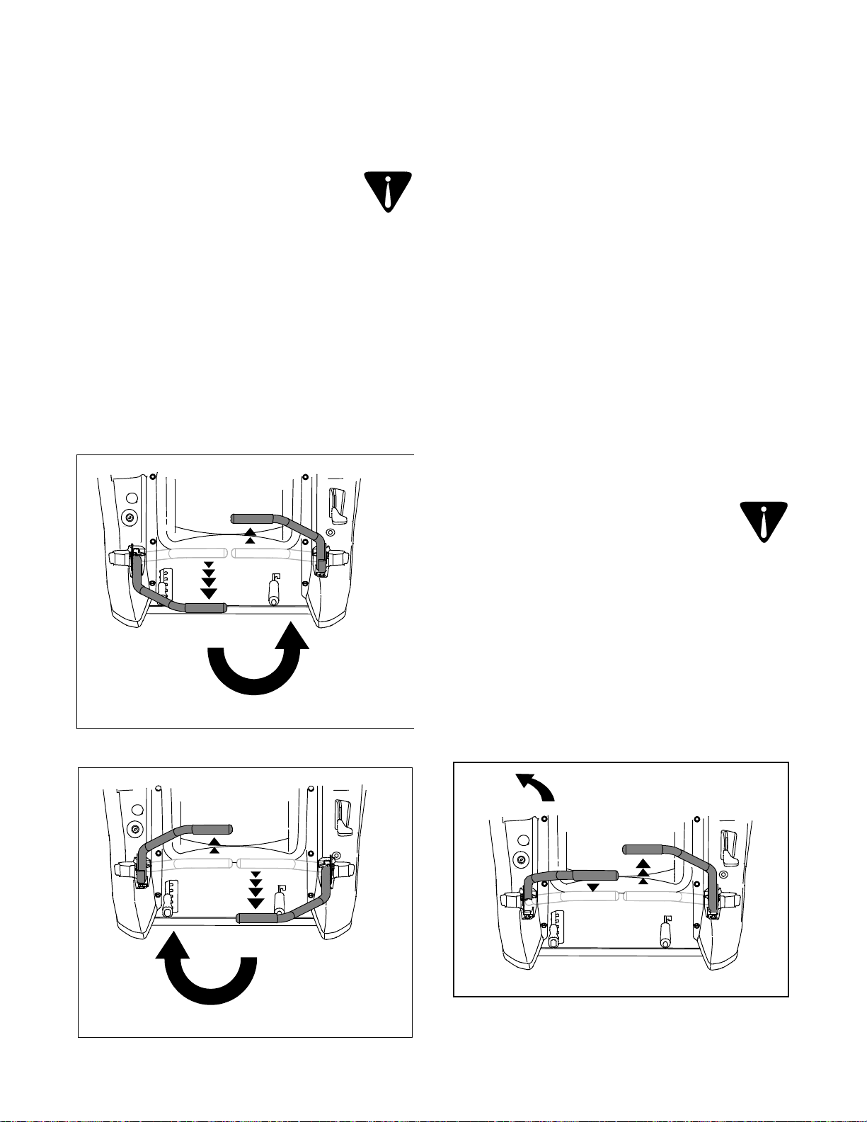
20
vers l’extérieur, au point mort.
blessé.
et le conducteur peut être gravement
pieds). Le tracteur risque de se retourner
augmentation de 2 ½ pi tous les 10
une pente supérieure à 15º (soit une
AVERTISSEMENT : Ne travaillez pas sur
s’il est dangereux de travailler sur la pente.
Utilisez l’inclinomètre à la page 10 pour déterminer
CONDUITE SUR UNE PENTE
« OFF » (Arrêt) et retirez la clé de contact.
- Placez le commutateur d’allumage à la position
position lente (sur le tracteur ZT50).
dernière position (sur le tracteur ZT42) ou à la
- Placez la manette de commande des gaz à la
Serrez le frein de stationnement.
-
- Poussez les deux leviers de direction à fond
Pour quitter le poste de conduite :
haute avec la manette de relevage.
• Relevez le plateau de coupe à la position la plus
mutateur.
• Débrayez la prise de force en abaissant le com-
pour arrêter le tracteur.
• Placez les deux leviers de direction au point mort
POUR ARRÊTER LE TRACTEUR
gauche vers l’arrière. Voir la Figure 18.
levier droit en tirant simultanément le levier
• Pour tourner à gauche, poussez lentement le
vers l’arrière. Voir la Figure 17.
gauche en tirant simultanément le levier droit
• Pour tourner à droite, poussez lentement le levier
direction au point mort.
Figure 18
• Arrêtez le tracteur en plaçant les deux leviers de
pelouse.
maîtrise du tracteur et endommager la
tracteur avance peut diminuer votre
TRACTEUR. Un virage sur place quand le
place, il est IMPÉRATIF D’ARRÊTER LE
AVERTISSEMENT : Pour tourner sur
Pour tourner sur place
virage sur place sur de l’herbe.
d’endommager la pelouse en effectuant un
IMPORTANT : Vous risquez davantage
direction choisie.
point mort tout en poussant l’autre levier, selon la
• Pour tourner sur place, placez l’un des leviers au
les deux leviers de direction est importante.
POUR TOURNER SUR PLACE VERS LA GAUCHE
Figure 17
Figure 16
• Le virage sera plus prononcé si la distance entre
VIRAGE À DROITE EN MARCHE ARRIÈRE
gauche. Voir la Figure 16.
POUR TOURNER SUR PLACE VERS LA DROITE
poussez le levier droit en avant du levier
- Pour tourner à droite en marche arrière,
Page 54

19
toujours derrière vous en reculant.
du tracteur avant de reculer. Regardez
Figure 15
derrière vous et par terre des deux côtés
AVERTISSEMENT : Regardez toujours
Conduite en marche arrière
virage sur place sur de l’herbe.
d’endommager la pelouse en effectuant un
IMPORTANT : Vous risquez davantage
direction choisie.
point mort tout en poussant l’autre levier, selon la
• Pour tourner sur place, placez l’un des leviers au
les deux leviers de direction est importante.
• Le virage sera plus prononcé si la distance entre
VIRAGE À GAUCHE EN MARCHE ARRIÈRE
Figure 13
Figure 15.
levier gauche en avant du levier droit. Voir la
- Pour tourner à gauche en reculant, poussez le
dans le sens du levier le plus en avant.
leviers soit en retrait de l’autre. Le tracteur tourne
leviers de direction de manière que l’un des
• Pour tourner en marche arrière, déplacez les
Pour tourner en marche arrière
point mort.
direction, surtout pour ralentir ou pour revenir au
VIRAGE À DROITE EN MARCHE AVANT
IMPORTANT : Ne lâchez jamais les leviers de
retrait du levier gauche. Voir la Figure 13.
mort pour arrêter le tracteur.
vitesse désirée ou placez les leviers au point
• Pour ralentir, poussez les leviers vers l’avant à la
Figure 12
- Pour tourner à droite, tirez le levier droit en
tracteur recule.
• Plus les leviers sont tirés vers l’arrière, plus vite le
Figure 14
Plus vite
Moins vite
VIRAGE À GAUCHE EN MARCHE AVANT
Point mort
CONDUITE EN MARCHE ARRIÈRE
retrait du levier droit. Voir la Figure 12.
- Pour tourner à gauche, tirez le levier gauche en
est tiré vers l’arrière.
tracteur tournera dans la direction du levier qui
Voir la Figure 14.
égale. Le tracteur commencera alors à reculer.
• Tirez lentement sur les deux leviers de façon
poussant un levier et en tirant sur l’autre. Le
les leviers de direction selon le besoin, en
• Pour tourner le tracteur en avançant, déplacez
Page 55

Figure 11
Point mort
18
direction.
TOUJOURS avant de changer de
votre maîtrise du tracteur. Ralentissez
d’endommager la pelouse et peut réduire
Un virage plus serré risque
virage en U dans la mesure du possible.
nous vous recommandons d’effectuer un
AVERTISSEMENT : Pour faire demi-tour,
Pour tourner le tracteur en avançant
point mort.
direction, surtout pour ralentir ou pour revenir au
IMPORTANT : Ne lâchez jamais les leviers de
les au point mort pour arrêter le tracteur.
ralentir le tracteur à la vitesse désirée ou placez-
• Tirez sur les leviers de direction vers vous pour
gauche respectivement et procédez comme suit :
leviers de direction avec les mains droite et
• Pour conduire le tracteur, tenez fermement les
loin à la position du volet de départ.
que la commande des gaz n’a pas été poussée trop
REMARQUE : Sur le modèle ZT42, assurez-vous
pendant la période d’apprentissage.
régime (2500-3000 tr/min. environ), mais seulement
préférable de ne pas conduire le tracteur à plein
pour tourner à plein régime. Pour vous exercer, il est
REMARQUE : Le moteur du tracteur a été conçu
3600 tr/min.)
vers l’avant à la position de plein régime (3500-
• Poussez la manette de la commande des gaz
et ajustez les leviers.
au même niveau au point mort, consult ez la section 3
REMARQUE : Si les leviers de direction ne sont pas
Figure 10
Moins vite
Plus vite
CONDUITE AVANT
l’avant, plus le tracteur avance vite.
• Plus on pousse les leviers de direction vers
cera à avancer. Voir la Figure 11.
et en douceur vers l’avant. Le tracteur commen-
• Déplacez les deux leviers de direction lentement
mortelles.
peut causer des blessures graves ou
tracteur et le faire se retourner, ce qui
direction peut affecter la stabilité du
mouvement brusque des leviers de
de direction lentement et en douceur. Un
AVERTISSEMENT : Déplacez les leviers
Conduite en marche avant
les leviers de direction au point mort.
arrêter le tracteur ; placez manuellement
LES LÂCHEZ PAS pour ralentir ou
fermement les leviers de direction. NE
AVERTISSEMENT : Tenez toujours
vers l’intérieur au point mort
Leviers de direction tirés
l’intérieur, au point mort. Voir la Figure 10.
• Tirez les leviers de direction droit et gauche vers
• Desserrez le frein de stationnement.
« RÉGLAGES ».
selon les instructions dans la section
pour utiliser les commandes. Réglez le siège
• Ajustez le siège à la position la plus confortable
reste sans surveillance.
Retirez la clé de contact si le tracteur
mort et serré le frein de stationnement.
direction à fond vers l’extérieur au point
la prise de force, poussé les leviers de
poste de conduite avant d’avoir débrayé
AVERTISSEMENT : Ne quittez pas le
arrêts soudains.
brusques, la vitesse excessive et les
AVERTISSEMENT : Évitez les démarrages
CONDUITE DU TRACTEUR
Page 56

17
conduire le tracteur en toute sécurité.
jusqu’à ce que vous vous sentiez à l’aise pour
manœuvrer le tracteur. Continuez à vous exercer
« Conduite du tracteur » pour vous habituer à
Suivez les instructions ci-dessous dans la section
arrière.
maximale en marche avant comme en marche
régime moyen et ne conduisez pas à la vitesse
pendant cette session. Réglez l’obturateur à un
choisie. La prise de force ne doit pas être embrayée
Amenez doucement votre tracteur dans la zone
pour vous exercer pendant au moins 30 minutes.
dégagé et plat, sans obstacles, piétons ou animaux,
Nous vous conseillons de choisir un endroit bien
plus maniable qu’un tracteur ordinaire.
un tracteur qui tourne sur lui-même est beaucoup
s’habituer à utiliser les leviers de direction, même si
différente de la conduite d’un tracteur ordinaire. Il faut
La conduite d’un tracteur qui tourne sur lui-même est
UTILISATION INITIALE
surveillée.
décharge de la batterie, si la machine n’est pas
éviter tout démarrage accidentel ou pour empêcher la
REMARQUE : Retirez toujours la clé de contact pour
(Arrêt) et retirez la clé de contact.
• Tournez la clé de contact à la position « OFF »
régime se stabilise au ralenti.
ralenti. Laissez tourner le moteur pour que le
• Placez la manette de la commande des gaz au
• Serrez le frein de stationnement.
fond vers l’extérieur, au point mort.
• Poussez les leviers de direction droit et gauche à
position « OFF » (Arrêt).
• Placez le commutateur de la prise de force à la
POUR ARRÊTER LE MOTEUR
câbles volants.
dès que possible pour éliminer le besoin de
• Faites vérifier et réparer le système électrique
volants dans l’ordre inverse.
instructions fournies, puis débranchez les câbles
• Faites démarrer le tracteur en panne selon les
batterie.
châssis du tracteur, le plus loin possible de la
branchez l’autre extrémité de ce câble sur le
borne négative de la batterie d’appoint, puis
• Branchez une extrémité de l’autre câble sur la
batterie d’appoint.
extrémité de ce câble sur la borne positive de la
positive de la batterie à plat, puis branchez l’autre
• Branchez une extrémité d’un câble sur la borne
batterie d’appoint comme suit :
tracteur, une batterie d’appoint sera utile. Branchez la
n’avez pas de chargeur et qu’il faut faire démarrer le
tourner le moteur, rechargez la batterie. Si vous
Si la charge de la batterie est insuffisante pour faire
de la batterie.
d’approcher des flammes ou étincelles
ou un masque de protection et évitez
aérée, portez des gants et des lunettes
vous que la zone de travail est bien
dégagent des gaz explosifs. Assurezcontiennent de l’acide sulfurique et
AVERTISSEMENT : Les batteries
VOLANTS
DÉMARRAGE DU MOTEUR PAR CÂBLES
DÉMARRER UN MOTEUR.
• Suivez les instructions ci-dessus pour FAIRE
l’essence qui vous reste de l’été.
facilite les démarrages. N’utilisez pas de
l’hiver. L’essence pour l’hiver est plus volatile et
• Utilisez une essence fraîche appropriée pour
qu’une batterie froide.
batterie réchauffée démarre plus facilement
• Assurez-vous que la batterie est en bon état. Une
moteur en route comme suit :
que la batterie est complètement chargée. Mettez le
d’utiliser une huile à moteur de la viscosité voulue et
est proche ou inférieure à 0º C (32ºF), assurez-vous
Pour faire démarrer un moteur lorsque la température
DÉMARRAGE PAR TEMPS FROID
Adressez-vous au concessionnaire local.
s’allume, arrêtez immédiatement le moteur.
d’affichage. Si le témoin lumineux de la batterie
• Vérifiez le compteur d’heures/panneau
travailler.
minutes à mi-régime avant de commencer à
• Laissez le moteur tourner pendant quelques
faire démarrer le moteur.
enrichir le mélange de carburant, sauf pour
départ. N’utilisez pas le volet de départ pour
abaissez le bouton pour ouvrir le volet de
4. Quand le moteur commence à chauffer,
de recommencer.
« OFF » (Arrêt) et attendez une minute avant
démarre pas, tournez la clé à la position
plus de 5 secondes à la fois. Si le moteur ne
tourner le moteur continuellement pendant
la dès que le moteur démarre ; ne faites pas
position « START » (Démarrage) et relâchez-
3. Tournez la clé de contact vers la droite, à la
Page 57

Figure 9
position débrayée.
prise de force à la
Commutateur de la
volet
commande du
bouton de
ZT50 - Tirez le
serré
droite au point mort
Levier de direction
16
position « CHOKE » (Volet de départ).
• Placez la manette de la commande des gaz à la
• Modèle ZT42 SEULEMENT
est à la position « Débrayée ». Voir la Figure 9.
• Vérifiez que le commutateur de la prise de force
de départ
gaz à la position du volet
manette de commande des
ZT-50 Déplacez la Tirez sur le bouton de la
de départ
gaz à la position du volet
manette de commande des
ZT-42 Tirez sur le bouton de la
• Serrez le frein de stationnement. Voir la Figure 9.
conduite.
• Le conducteur doit être assis au poste de
9.
fond vers l’extérieur, au point mort. Voir la Figure
• Poussez les leviers de direction droit et gauche à
fonctionnement du système de sécurité.
défectueux. Vérifiez fréquemment le bon
composant quelconque du système est
N’utilisez pas le tracteur si un
assure la protection du conducteur.
équipé d’un système de sécurité qui
AVERTISSEMENT : Ce tracteur est
moteur en route.
poste de conduite avant de mettre le
sécurité, le conducteur doit être assis au
AVERTISSEMENT : Par mesure de
Frein de stationnement
gauche au point mort
Levier de direction
DÉMARRAGE DU MOTEUR
avant de remettre le moteur en marche.
force doit être placé à la position « OFF » (Arrêt)
• REMARQUE : Le commutateur de la prise de
la position « rapide ».
2. Déplacez la manette de commande des gaz à
manette à cette position.
peut ne pas être nécessaire de placer la
fermé. Remarque : Si le moteur est chaud, il
départ vers la position du volet de départ
1. Tirez le bouton de commande du volet de
• Modèle ZT50 SEULEMENT
carburant, sauf pour faire démarrer le moteur.
volet de départ pour enrichir le mélange de
position « FAST » (Rapide). N’utilisez pas le
au-delà du point de résistance, jusqu’à la
manette de la commande des gaz vers vous,
2. Quand le moteur tourne, tirez lentement la
de recommencer.
« OFF » (Arrêt) et attendez une minute avant
démarre pas, tournez la clé à la position
plus de 5 secondes à la fois. Si le moteur ne
tourner le moteur continuellement pendant
la dès que le moteur démarre ; ne faites pas
position « START » (Démarrage) et relâchez-
1. Tournez la clé de contact vers la droite, à la
position.
pas être nécessaire de plac er la manette à cette
REMARQUE : Si le moteur est chaud, il peut ne
stationnement soit serré ou non.
la prise de force est embrayée, que le frein de
conducteur quitte le poste de conduite alors que
• Le système de sécurité arrête le moteur si le
serrer le frein de stationnement.
conducteur quitte le poste de conduite avant de
• Le système de sécurité arrête le moteur si le
le frein de stationnement est serré.
position autre que la position au point mort quand
direction droite ou gauche se trouvent à une
de sécurité arrête le moteur si les leviers de
desserrant le frein de stationnement, le système
• Pour éviter tout mouvement brusque en
force est embrayée.
stationnement n’est pas serré et si la prise de
l’extérieur au point mort, si le frein de
gauche ne sont pas poussés à fond vers
démarrer si les leviers de direction droit ou
• Ce système empêche le moteur de tourner ou de
et adressez-vous au concessionnaire le plus proche.
fonctionne pas correctement, n’utilisez pas le tracteur
assure la protection du conducteur. Si ce système ne
Ce tracteur est muni d’un système de sécurité qui
SYSTÈME DE SÉCURITÉ
Page 58

15
glissante.
et une maîtrise totale du tracteur.
maximum au conducteur, une excellente visibilité
• Ajustez le siège pour assurer un confort
• Vérifiez la pression des pneus.
Voir la notice d’utilisation du moteur.
• Nettoyez la cartouche du filtre à air si besoin est.
• Vérifiez le niveau d’huile dans le moteur.
sont pas recommandés.
Les autres mélanges d’essence et d’éther ne
MTBE par volume) peuvent aussi être utilisés.
et d’essence (jusqu’à un maximum de 15% de
• Les mélanges de méthyl-tert-butyléther (MTBE)
d’essence et d’alcool ne sont pas recommandés.
d’essence sans plomb). Les autres mélanges
alcool (jusqu’à 10% d’alcool éthylique et 90%
• Vous pouvez utiliser un mélange d’essence-
dans le système.
précédente afin de minimiser les dépôts de gomme
quantités. N’utilisez pas de l’essence de l’année
REMARQUE : Achetez l’essence en petites
émissions de gaz polluants sont réglementées.
ne doit pas être utilisée dans les régions où les
toxiques. L’essence à plomb est déconseillée et
combustion et elle réduit les gaz polluants
elle laisse moins de dépôts dans la chambre de
• Une essence sans plomb est recommandée car
fraîche ayant un indice d’octane de 87 ou plus.
le plein avec une essence sans plomb propre
Vous obtiendrez de meilleurs résultats en faisant
avec une essence sans plomb propre fraîche.
• Ce moteur est conçu pour fonctionner seulement
à entretenir convenablement votre tracteur.
notice a été préparée pour vous aider à utiliser et
conduire le tracteur pour la première fois. Cette
• Lisez attentivement la notice d’utilisation avant de
AVANT D’UTILISER LE TRACTEUR
le bouchon d’essence à fond.
moteur refroidisse avant de faire le plein. Serrez
chaud. Attendez quelques minutes pour que le
le moteur tourne ou si le moteur est encore
• Ne faites pas le plein du carburant pendant que
etc.
l’herbe sèche, des feuilles mortes ou des débris,
sur des matériaux combustibles comme de
• N’arrêtez pas le tracteur et ne le stationnez pas
place.
complètement avant d’effectuer un virage sur
• Ralentissez avant de tourner et arrêtez-vous
• Évitez de travailler sur une surface instable ou
risque de se retourner.
différent sans le plateau de coupe et le tracteur
coupe. En effet, l’équilibre du tracteur est
• N’utilisez pas le tracteur sans le plateau de
de continuer à travailler.
attendez que les véhicules soient passés avant
proximité d’une route. Arrêtez le tracteur et
• Soyez très prudent quand vous travaillez à
démarrage et à l’arrêt.
évitez tout mouvement brusque, en particulier au
• Déplacez les leviers de direction en douceur et
de nettoyage.
avant d’effectuer toute opération d’entretien ou
pièces en mouvement se soient immobilisées
retirez la clé de contact. Attendez que toutes les
frein de stationnement, arrêtez le moteur et
à fond vers l’extérieur au point mort, serrez le
prise de force, poussez les leviers de commande
• Avant de quitter le poste de conduite, débrayez la
peut se retourner.
terrain plus pentu est dangereux car le tracteur
tracteur sur une pente supérieure à 15º. Tout
sur un terrain en pente. Ne conduisez jamais le
• Dans la mesure du possible, évitez de travailler
spectateurs
• NE dirigez PAS l’éjection de la tondeuse vers des
de reculer et pendant la manœuvre.
derrière vous et des deux côtés du tracteur avant
spectateurs et animaux de compagnie. Regardez
• PAS DE PASSAGERS ! Éloignez tous les
mouvement.
place. Ne vous approchez pas des pièces en
• Laissez tous les dispositifs de protection en
poussés à fond vers l’extérieur, au point mort.
leviers de direction droit et gauche doivent être
débrayée, le frein de stationnement serré et les
de conduite. La prise de force doit être
tracteur. Le conducteur doit être assis au poste
mettre le moteur en marche ou avant d’utiliser le
• Familiarisez-vous avec les commandes avant de
autorisées à l’utiliser.
mode d’emploi de ce tracteur doivent être
les personnes qui se sont familiarisées avec le
BLESSURES GRAVES ou MORTELLES. Seules
TOUTE SÉCURITÉ. Ne risquez pas des
tracteur. Apprenez à utilisez cette machine EN
• INSTRUCTIONS – Lisez la notice d’utilisation du
CONSIGNES DE SÉCURITÉ
CHAPITRE 2: UTILISATION
Page 59

14
doit être serré quand le moteur est mis en marche.
serré, le moteur va caler. Le frein de stationnement
au point mort quand le frein de stationnement est
gauche ne sont pas poussés à fond vers l’extérieur
IMPORTANT : Si les leviers de direction droit et
frein de stationnement.
puis abaissez-la complètement pour desserrer le
• Sortez la manette de la fente en J vers la droite,
serrer le frein de stationnement.
gauche, puis abaissez-la dans la fente en J pour
• Relevez complètement la manette vers la
et permet de serrer le frein de stationnement.
Elle se trouve sur l’avant à gauche du cadre du siège
O. Manette du frein de stationnement
poussez-le pour ouvrir le volet de départ.
Tirez sur le bouton pour fermer le volet de départ et
Le bouton du volet de départ contrôle sa position.
SEULEMENT
N. Commande du volet de départ – Modèle ZT50
point de résistance..
jusqu’à ce que vous sentiez qu’elle a passé le
manette de commande des gaz vers l’arrière
tourne et qu’il s’est réchauffé, déplacez la
au démarrage. Voir la Figure 8. Quand le moteur
l’avant à la position « CHOKE » (Volet de départ)
manette de commande des gaz à fond vers
• Modèle ZT42 SEULEMENT – Poussez la
diminuer le régime du moteur.
• Tirez sur la manette de commande des gaz pour
conduit et que le plateau de coupe est embrayé.
rapide (plein régime) quand le tracteur est
fonctionne mieux avec la manette à la position
pour augmenter le régime du moteur. Le moteur
• Poussez la manette de la commande des gaz
Figure 8
slow position.
This symbol indicates the
fast position.
This symbol indicates the
départ.
position du volet de
Ce symbole indique la
position lente.
Ce symbole indique la
position rapide.
Ce symbole indique la
CHOKE
ZT50
ZT42
régime du moteur sera maintenu.
siège du conducteur. À une position donnée, le
Elle se trouve sur la console gauche, à la gauche du
M. Manette de la commande des gaz
besoin, serrez le frein de stationnement.
trouve à la position « START » (Démarrage). Au
Poussez les leviers de direction vers l’extérieur.ge se
trouvent à une position autre que le point mort.
quand les leviers de direction droit et gauche se
d’allumage se trouve à la position « START » et
Ce témoin s’allume aussi quand le commutateur
Page 60

13
stationnement.
(Démarrage). Au besoin, serrez le frein de
d’allumage se trouve à la position « START »
si le moteur ne tourne pas quand le commutateur
position « START » (Démarrage). Vérifiez ce témoin
et quand l’interrupteur de contact se trouve à la
se trouve à la position « DISENGAGED » (Desserré)
Ce témoin s’allume quand le frein de stationnement
Figure 7)
Indicateur du frein de stationnement serré (Voir la
(Débrayée).
la prise de force à la position « DISENGAGED »
(Démarrage). Au besoin, placez l’interrupteur de
contact se trouve à la position « START »
moteur ne tourne pas quand l’interrupteur de
« START » (Démarrage). Vérifiez ce témoin si le
l’interrupteur d’allumage se trouve à la position
« ENGAGED » (Embrayée) et quand
prise de force est relevé à la position
• Ce témoin s’allume quand le commutateur de la
Figure 7)
Indicateur de la prise de force embrayée (Voir la
quand le moteur démarre.
trouve à la position « ON », mais doit s’éteindre
s’allumer quand le commutateur de l’allumage se
REMARQUE : L’indicateur de la pression d’huile peut
faire inspecter le tracteur et le moteur.
Figure 7
tracteur est mis en route pendant cet intervalle
pendant cinq minutes chaque fois que le moteur du
150 à 152 heures, etc.). Le témoin lumineux clignote
de deux heures (50 à 52 heures, 100 à 102 heures,
fonctionnement enregistré. L’intervalle d’entretien est
pendant cinq minutes après toutes les 50 heures de
clignote « CHG » , « OIL » et le nombre d’heures
intervalles entre les vidanges d’huile. Le témoin
Le témoin lumineux rappelle aussi au conducteur les
nombre d’heures accumulées.
brièvement affichée. L’affichage passe ensuite au
s’allume et la tension de la batterie est
(Marche), le témoin lumineux de la batterie
• Quand la clé se trouve à la position « ON »
moteur.
instructions de cette notice d’utilisation et de celle du
d’effectuer les entretiens nécessaires selon les
fonctionnement réelles du traceur pour vous assurer
position « ON » (Marche). Notez les heures de
durée quand l’interrupteur de contact se trouve à la
REMARQUE : Le compteur d’heures enregistre la
chiffre le plus à droite).
de fonctionnement du tracteur (en dixièmes d’heure –
Il enregistre sur un affichage numérique les heures
Compteur d’heures
allumé. Contactez votre concessionnaire pour
le moteur fonctionner lorsque cet indicateur est
cherchez en les causes possibles. Ne laissez pas
marche, arrêtez le moteur immédiatement et
l’indicateur s’allume alors que le moteur est en
serré
stationnement
frein de
Indicateur du
embrayée
force
prise de
de la
Indicateur
d’huile du moteur est trop basse. Dans le cas où
• Cet témoin d'alerte indique que la pression
(en option)
Indicateur de la pression d’huile voir la Figure 7)
ou adressez-vous au concessionnaire.
d’heures
Compteur
l’huile
la presion
Indicateur der
batterie
de la
Indicateur
charge pour déterminer les raisons possibles et/
fonctionne, vérifiez la batterie et le système de
l’affichage s’allument pendant que le tracteur
sur le compteur d’heures. Si ce témoin et
volt). La tension de la batterie est aussi affichée
la batterie est tombée à moins de 11,5 (+0.5/-1
• Ce témoin s’allume pour indiquer si la tension de
(Marche).
d’allumage se trouve à la position « On »
brièvement affichée quand le commutateur
• Ce témoin s’allume et la tension de la batterie est
Indicateur de la batterie (Voir la Figure 7)
incendie.
moteur chaud risque de provoquer un
inflammable et des éclaboussures sur un
L’essence est un produit hautement
refroidi avant de refaire le plein.
tourne. Attendez que le moteur ait
plein d’essence pendant que le moteur
AVERTISSEMENT : Ne faites jamais le
siège du conducteur.
Il se trouve sur la console gauche, sur la gauche du
L. Compteur d’heures/Panneau d’affichage
Panneau des indicateurs
Resserrez toujours bien le capuchon sur le réservoir.
du moteur.
d’huile recommandés dans la notice d’utilisation
d’entretien. Respectez les intervalles de vidange
sens des aiguilles d’une montre pour le serrer.
du réservoir et faites environ un quart de tour dans le
Enfoncez le capuchon sur le goulot de remplissage
Page 61

12
de le détacher du tracteur.
le capuchon est attaché au tracteur. N’essayez pas
relevez-le pour le retirer. Pour qu’il ne se perde pas,
Tournez le capuchon d’un quart de tour environ et
Il se trouve vers le milieu de la console de gauche.
K. Capuchon du réservoir d’essence
siège. Voir les instructions dans le CHAPITRE 3 :
et permet d’ajuster la position d’avant en arrière du
Elle se trouve sous le siège, sur l’avant et à gauche,
J. Manette de réglage du siège (non représentée)
Il se trouve sur l’arrière de la console gauche.
(DÉMARRAGE)
START
Figure 5
moteur démarre.
le moteur. Lâchez immédiatement la clé pour que le
START (DÉMARRAGE) – Le démarreur fait tourner
est sous tension.
ON (MARCHE) – Le système électrique du tracteur
électrique est hors circuit.
OFF (ARRÊT) – Le moteur est arrêté et le système
H. Plateau de rangement
droite du siège du conducteur.
Il se trouve sur l’arrière de la console droite, sur la
ON (MARCHE)
STOP
OFF (ARRÈT)
G. Porte-gobelet
transmissions.
sol peut causer de graves dégâts aux
les roues arrière sont en contact avec le
le tracteur. Remorquer le tracteur quand
AVERTISSEMENT: Ne remorquez jamais
trouvent dans le CHAPITRE 4 : ENTRETIEN.
instructions d’emploi de cette caractéristique se
manuellement sur de courtes distances. Les
hydrostatiques qui permet de pousser le tracteur
ouvrent une dérivation dans les transmissions
Lorsqu’elles sont embrayées, les deux commandes
châssis, juste à côté de chaque roue arrière.
transmissions) se trouvent sous la plate-forme du
Ces commandes (une pour chacune des
(non représentées)
F. Commandes de dérivation de la transmission
Figure 6
Vous noterez trois positions, à savoir :
droite du poste de conduite..
Cet interrupteur se trouve sur la console droite, à la
D. Interrupteur de contact
CHAPITRE 2 : UTILISATION.
les instructions d’emploi de ces leviers dans le
Une certaine pratique est nécessaire. Vous trouverez
telles commandes par rapport à un tracteur ordinaire.
en fait très différent de conduire un tracteur équipé de
commandent toutes les manœuvres du tracteur. Il est
de gauche respectivement. Par conséquent, ils
Chaque levier contrôle la transmission de droite ou
démarrer le moteur.
vers l’extérieur au point mort pour pouvoir faire
de le quitter. Les leviers doivent être poussés à fond
pour permettre au conducteur d’accéder au siège ou
peuvent être poussés vers l’extérieur au point mort,
côté du siège du conducteur. Ces leviers articulés
Les leviers droit et gauche se trouvent de chaque
C. Leviers de direction droit et gauche
l’encoche correspondante.
poussez la manette vers la droite pour la placer dans
le plateau de coupe se trouve à la position voulue,
soulevez-la pour relever le plateau de coupe. Quand
la gauche pour abaisser le plateau de coupe, ou
.
la position « débrayée » au démarrage
Le commutateur de la prise de force doit se trouver à
abaissez-le pour la débrayer.
commutateur pour embrayer la prise de force ou
base du vilebrequin du moteur. Relevez le bouton du
d’embrayer la prise de force électrique, installée à la
Le commutateur de la prise de force permet
du conducteur.
Il se trouve sur la console droite, à la droite du siège
E. Commutateur de la prise de force
contact quand le tracteur n’est pas utilisé.
et/ou la décharge de la batterie, retirez la clé de
REMARQUE : Pour éviter tout démarrage accidentel
Dégagez la manette de l’encoche en l’abaissant vers
et sert à relever ou à abaisser le plateau de coupe.
Elle se trouve sur l’avant et à droite du cadre du siège
B. Manette de relevage du plateau de coupe
(au plus haut).
du plateau de coupe, de 1 ½ po ( au plus bas) à 4 po
représente une différence de ½ pouce de la hauteur
droite du cadre du siège. Chaque encoche
Il comporte six encoches et se trouve sur l’avant et à
A. Indicateur de la hauteur du plateau de coupe
assis sur le siège.
et ARRIÈRE s’entendent de la positionde direction,
REMARQUE : Les côtés GAUCHE, DROIT, AVANT
Page 62

11
G Porte-gobelet O Manette d’embrayage du frein de stationnement
F Tige de dérivation de la transmission (non repésentée) N Commande du volet de départ - Modèle ZT50 SEULEMENT
E Commutateur de la prise de force M Manette de la commande des gaz
D Interrupteur de contact L Compteur d’heures/panneau d’affichage
C Leviers de direction droit et gauche K Bouchon du réservoir de carburant
B Manette de relevage du plateau de coupe J Manette de réglage du siège (non représentée)
A Indicateur de la hauteur du plateau de coupe H Plateau de rangement
Figure 4
H
K
G
F
E
D
C
B
J
A
O
C
F
L
M
N
CHAPITRE 1: COMMANDES ET CARACTÉRISTIQUES
Page 63

UN POTEAU ÉLECTRIQUE
OU UN POTEAU DE CLÔTURE
LE COIN D’UN BÂTIMENT
10
°
5
1
E
D
É
IT
V
I
L
ÉC
D
E
N
U
E
T
N
SE
É
R
P
E
R
I
U
Q
É,
L
L
I
T
N
I
O
P
E
L
R
U
S
Z
E
I
L
P
15°
AVERTISSEMENT
DANGEREUX DE TRAVAILLER.
VISEZ ET ALIGNEZ AVEC UN ARBRE
SERVER-VOUS DE CET INCLINOMÈTRE POUR DÉTERMINER LES PENTES SUR LESQUELLES IL SERAIT
INCLINOMÈTRE
Ne vous servez pas de le tracteur sur des pentes supérieures à 15° (soit une déclivité de 2-1/2 pi par 10 pi). Un tracteur à siège
risque en effet de se retourner et son conducteur peut être gravement blessé. Il est également difficile de conserver un bon
appui en marchant derrière un tracteur. Vous risquez de glisser et de vous blesser.
Utilisez les tracteurs À SIÈGE parallèlement à la pente, jamais en travers.
Page 64

9
pouvoir poursuivre votre consultation.
déterminer l’emplacement de ces numéros. On vous demandera d’enregistrer le numéro de série avant de
Préparez vos numéros de modèle et de série avant de téléphoner. Veuillez lire le chapit re précédent pour
1-800-668-1238.
2.Appelez un agent du service après-vente au
1.Visitez le site www.cubcadet.ca où vous trouverez de nombreuses suggestions utiles.
Choisissez l’une des options ci-dessous:
les spécialistes sont à votre disposition.
commandes, le fonctionnement ou l’entretien de la machine,
Si l’assemblage de cette machine vous pose des problèmes ou pour toute question concernant les
Veuillez retourner la machine au détaillant qui vous l’a vendue, sans vous adresser d’abord au service après-vente.
SERVICE APRÈS-VENTE
moteur empaqueté séparément avec votre équipment.
puissance, caractéristique, garantie et service. Pour plus de renseignements, consultez votre notice d’utilisation du
Le fabricant du moteur est responsable pour tout questions relié au moteur en ce qui concerne la perfomance,
INFORMATION DE MOTEUR
KITCHENER, ON N2G 4J1
Recopiez ici le numéro de série:
CUB CADET CANADA
XXXXXXXXXXX
Recopiez ici le numéro de modèle:
Numéro de série
Serial Number
XXX-XXXXXX
Numéro de modèle
Model Number
• Pour le localisser, basculez le siège vers l’avant et examinez le support de pivotement du siège sous celui-cil.
vous addresser au service après-vente ou concessionaire local.
renseignements s’avèront très importants si vous utilisez le site web du fabricant et/ou vous devez
signalétique et recopier les renseignements qui s’y trouvent dans la notice d’utilisation. Ces
Avant d’utiliser la tracteur de pelouse pour la première fois, veuillez localiser sa plaque
lire attentivement et vous assurer de bien comprendre toutes les instructions.
renseignements nécessaires à l’assemblage, à la préparation et à l’entretien de votre machine. Veuillez donc la
Cette notice d’utilisation est une pièce importante de votre nouveau tracteur de pelouse. Elle vous fournit les
POUR TROUVER LE NUMÉRO DE MODÈLE
Page 65
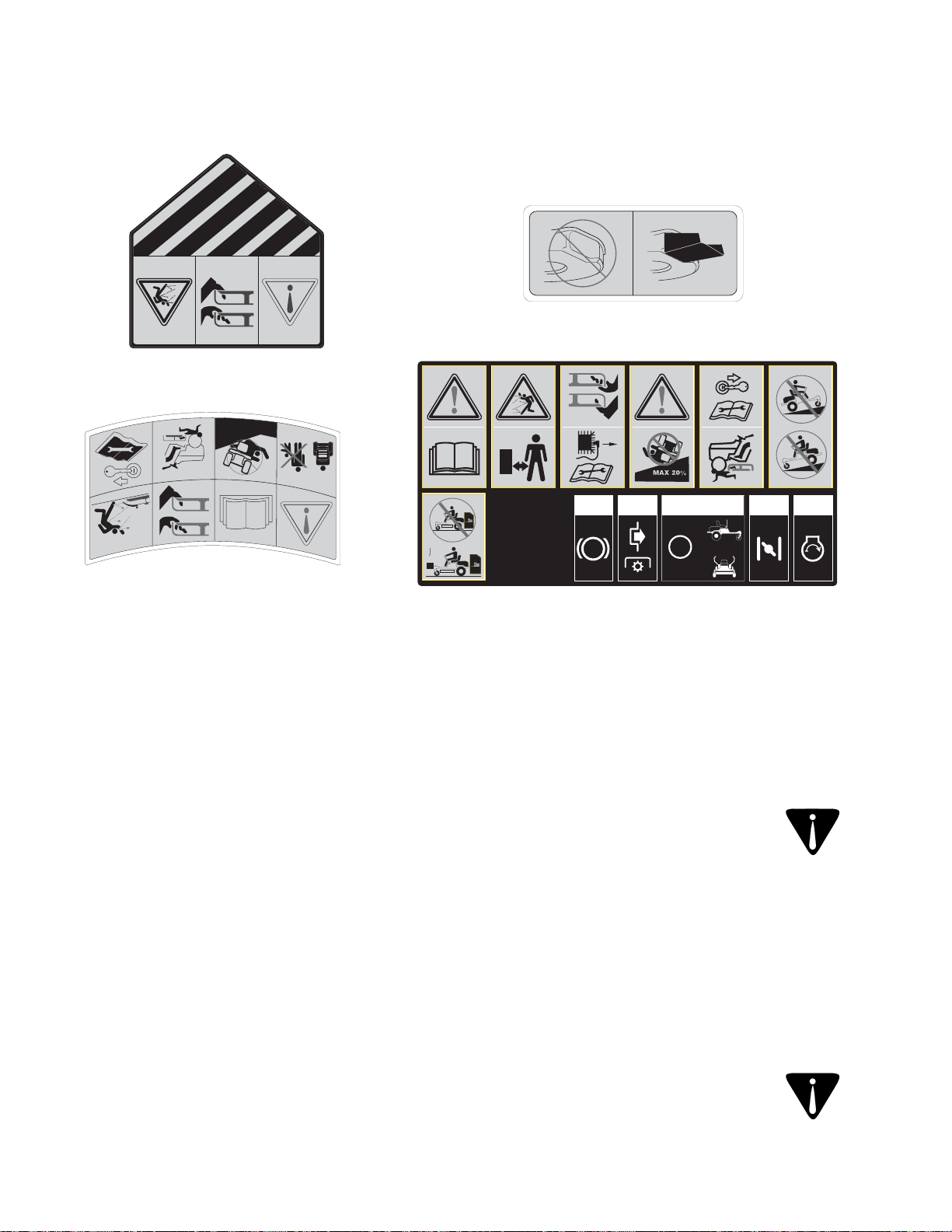
S30544
8
S30296
%
MAX 20
2
kg
peut causer des accidents et des blessures graves ou mortelles.
usés de façon excessive. Le non-respect de ces recommandations
niques et de sécurité sont en bon état de marche et ne sont pas
technique agréée pour vous assurer que tous les dispositifs mécaneuve ou faites inspecter la machine chaque année par une station
me de cette durée de vie utile moyenne, achetez une machine
moyenne de sept (7) ans, ou 60 heures de fonctionnement. Au terprotection de l’environnement), ce produit a une durée de vie utile
Environmental Protection Agency” (EPA - Agence américaine de
mission sur la sécurité des produits de consommation) et la “U.S.
D’après la Consumer Products Safety Commission (CPSC - Com-
Durée de vie utile moyenne
P
3 51
F
=
N
R
4
+
ÉTIQUETTES DE SÉCURITÉ
figurent dans cette notice d’utilisation
personnes qui ont lu, qui comprennent et qui respectent les avertissements et les instructions qui
AVERTISSEMENT:VOTRE RESPONSABILITÉ : Ne permettez l’utilisation de cette machine qu’à des
de cette machine.
fournir un pare-étincelles pour le pot d’échappement
La station technique agréée la plus proche peut vous
bon état de marche par l’utilisateur de la machine.
Si un pare-étincelles est utilisé, il doit être maintenu en
provinciaux ou locaux (le cas échéant).
formément aux lois et règlements
teur n’est pas muni d’un pare-étincelles, cond’herbe si le système d’échappement du moentretenu, recouvert de broussailles ou
elle ne doit pas être utilisée sur un terrain non
équipée d’un moteur à combustion interne et
AVERTISSEMENT : Cette machine est
Pare-étincelles
Page 66

7
Three Way Catalyst (TWC) le cas échéant.
sions de gaz suivants : Engine Modification (EM) et
peuvent être dotés des systèmes de contrôle des émisfonctionner avec de l’essence sans plomb ordinaire et
SORE (petit équipement hors route) sont certifiés pour
trices de la Californie et de l’agence EPA fédérales pour
Les moteurs certifiés conformes aux normes régula-
Avis concernant les émissions de gaz
régulateur.
gereuses. Ne modifiez jamais le réglage de l’usine du
entraîner son fonctionnement à des vitesses danrégulateur peut provoquer l’emballement du moteur et
pas du tout le moteur. Toute modification du réglage du
Pour éviter toute blessure grave ou fatale, ne modifiez
Ne modifiez pas le moteur
nature et à l’environnement.
des déchets et liquides qui risquent de nuire à la
14. Respectez les règlements concernant l’élimination
remplacez-les au besoin.
13. Prenez soin des étiquettes d’instructions et
fonctionnement sans danger.
maintient le moteur à son régime maximal de
laissez pas le moteur s’emballer. Le régulateur
12. Ne modifiez pas le réglage du régulateur et ne
performances inférieures et réduire la sécurité.»
l’équipement d’origine peut causer des
pièces non conformes aux caractéristiques de
des pièces authentiques seulement. «L’emploi de
éléments et remplacez-les immédiatement avec
Par mesure de sécurité, vérifiez souvent les
pièces mobiles ou causer la projection de débris.
endommagés et, par conséquent, exposer les
goulotte d’éjection peuvent s’user et être
11. Les éléments du sac à herbe et le clapet de la
réparations quand le moteur tourne.
10. N’essayez jamais de faire des réglages ou des
marche.
éventuels avant de remettre la machine en
soigneusement la machine. Réparez les dégâts
moteur, débranchez le fil de la bougie et examinez
9. Si vous heurtez un objet, arrêtez immédiatement le
Vérifiez souvent qu’ils fonctionnent bien.
8. Ne modifiez jamais les dispositifs de sécurité.
toujours en bon état de marche.
sont bien serrés pour que l’équipement soit
7. Assurez-vous que tous les écrous, boulons et vis
en les manipulant.
chiffon ou portez des gants et faites très attention
blessures graves. Enveloppez les lames avec un
6. Les lames sont coupantes et peuvent causer des
sécurité.»
causer des performances inférieures et réduire la
aux caractéristiques de l’équipement d’origine peut
seulement. «L’emploi de pièces non conformes
Remplacez-les par des lames authentiques
excessive, tout fendillement.
visuellement les lames pour détecter toute usure
montage du moteur sont bien serrés. Examinez
5. Vérifiez souvent que les lames et les boulons de
adressez-vous à la station technique agréée.
d’utilisation. S’il ne fonctionne pas correctement,
selon les renseignements dans la notice
verrouillage de sécurité fonctionne correctement,
4. Vérifiez régulièrement que le système de
technique agréée.
faites examiner la machine par une station
lames. Si elles ne s’arrêtent pas dans ce délai,
l’utilisation de la commande de débrayage des
s’immobilisent dans les 5 secondes qui suivent
3. Vérifiez régulièrement que les lames
accidentel.
moteur— pour empêcher tout démarrage
le fil de la bougie et mettez-le à la terre contre le
pièces mobiles se sont immobilisées. Débranchez
machine, vérifiez que les lames et toutes les
2. Avant de nettoyer, de réparer ou d’examiner la
inodore très dangereux.
contiennent du monoxyde de carbone, un gaz
local clos car les gaz d’échappement du moteur
1. Ne faites jamais fonctionner la machine dans un
ENTRETIEN GÉNÉRAL :
moins 5 minutes avant de la remiser.
m. Laissez la machine refroidir pendant au
sèche-linge, etc.)
une étincelle (chauffe-eau à gaz, radiateur,
d’essence à l’intérieur s’il y a une flamme,
l. Ne remisez jamais la machine ou les bidons
enlevez tous les débris imbibés d’essence.
éclaboussures de carburant ou d’huile et
feuilles et autres saletés. Essuyez les
débarrassant le moteur des brins d’herbe,
k. Limitez les risques d’incendie en
avant de la remettre en marche.
Déplacez la machine et attendez 5 minutes
éclaboussure sur le moteur et la machine.
j. En cas de débordement, essuyez toute
i. Resserrez bien le capuchon d’essence.
Page 67

pour permettre l’expansion du carburant.
Laissez un espace d’un demi-pouce environ
h. Ne faites jamais déborder le réservoir.
minutes avant de faire le plein.
moteur refroidir pendant au moins deux
moteur tourne ou s’il est chaud. Laissez le
n’ajoutez pas d’essence pendant que le
g. N’enlevez jamais le capuchon d’essence et
f. Ne faites jamais le plein à l’intérieur.
ou toute autre chaleur incandescente.
e. Éteignez toute cigarette ou pipe, tout cigare
de blocage en position ouverte.
N’utilisez pas un gicleur équipé d’un dispositif
bidon jusqu’à ce que le plein soit terminé.
du réservoir d’essence ou avec l’ouverture du
d. Maintenez le gicleur en contact avec le bord
que directement de la pompe à essence.
possible, faites le plein avec un bidon plutôt
faites le plein par terre. Si cela n’est pas
l’équipement motorisé de la remorque et
c. Dans la mesure du possible, déchargez
votre véhicule avant de les remplir.
Placez toujours les bidons par terre et loin de
est recouvert d’un revêtement en plastique.
à l’arrière d’une camionnette dont le plancher
b. Ne faites jamais le plein dans un véhicule, ni
homologués seulement.
a. Remisez le carburant dans des bidons
vêtements.
Rincez votre peau et changez immédiatement de
peau ou sur vos vêtements s’enflammaient.
grièvement blessé si des éclaboussures sur votre
vapeurs risquent d’exploser. Vous pouvez être
s’agit d’un produit extrêmement inflammable et les
Faites très attention en manipulant de l’essence. Il
pente.
supplémentaire pour vous arrêter.
du tracteur sur des pentes.
la perte de traction et par conséquent de contrôle
remorqué.
remorqué et au remorquage sur pente.
quant aux limites de poids de l’équipement
d’attelage.
l’équipement remorqué ailleurs qu’au point
attelage de remorquage. N’accrochez pas
6
1. Pour éviter toute blessure ou dégât matériel :
MANIPULATION DE L’ESSENCE :
ENTRETIEN
6. Ne passez pas au point mort pour descendre une
5. Avancez lentement et prévoyez une distance
4. Le poids de l’équipement remorqué peut entraîner
3. Ne transportez jamais quiconque sur l’équipement
2. Respectez les recommandations du fabricant
1. Ne remorquez qu’avec une machine équipée d’un
REMORQUAGE
la surveillance étroite d’un adulte.
apprendre à utiliser la machine et s’en servir sous
machine et les consignes de sécurité. Ils doivent
doivent lire et comprendre le mode d’emploi de la
ans d’utiliser la machine. Des enfants plus âgés
2. Ne permettez jamais à des enfants de moins de 14
utilisation non autorisée.
n’est pas surveillée pour empêcher son
h. Retirez la clé de contact quand la machine
se brûler.
moteur chaud ou en marche. Ils risquent de
g. Ne laissez pas des enfants s’approcher d’un
proximité.
enfants ou autres personnes se trouvent à
Mode» (Marche arrière - Prudence) si des
N’utilisez pas la mode «Reverse Caution
lames avant d’enclencher la marche arrière.
marche arrière, débrayez toujours la ou les
f. Pour éliminer tout risque d’accident en
peuvent vous empêcher de voir un enfant.
buissons, d’arbres et d’autres objets qui
d’angles morts, de buissons, de portails, de
e. Faites très attention en vous approchant
fonctionnement sécuritaire de la machine.
et d’être grièvement blessés ou de gêner le
lames ne tournent pas. Ils risquent de tomber
d. Ne transportez jamais d’enfants, même si les
pour éviter les jeunes enfants.
regardez toujours derrière vous et sur le sol
c. Pour éviter les accidents en reculant,
enfants s’approchent de la zone de travail.
b. Restez vigilant et arrêtez la machine si des
autre que le conducteur de la machine.
placez-les sous la surveillance d’un adulte
a. Éloignez les enfants de la zone de travail et
avez vus.
supposez jamais qu’ils vont rester là où vous les
ne se rendent pas compte des dangers. Ne
attirés par une machine et la tonte de l’herbe. Ils
présence d’enfants. Les enfants sont souvent
conducteur n’est pas toujours très vigilant en
1. Un accident grave risque de se produire si le
ENFANTS
tracteur peut se renverser).
limités, l’accessoire peut se mettre en crabe et le
accélérer, le freinage et la direction peuvent être
perte de contrôle du tracteur (le tracteur peut
tendance à pousser le tracteur et peut causer la
supérieures à 5°. Le poids supplémentaire a
(remorque chargée, rouleau, etc.) sur des pentes
6. Ne remorquez pas des accessoires lourds
réduction de traction peut faire déraper le tracteur.
5. Ne coupez pas l’herbe si elle est mouillée. La
4. N’utilisez pas le sac à herbe sur des pentes raides.
Page 68

5
pied à terre.
3. N’essayez pas de stabiliser la machine en mettant
de l’accotement peut renverser la machine.
Une roue dans le vide ou l’affaissement soudain
2. Ne tondez pas près d’une falaise ou d’un talus.
progressivement en descendant si possible.
soit nécessaire; tournez alors lentement et
1. Ne tournez pas sur une pente à moins que cela
À NE PAS FAIRE :
blessures graves.
machine et la faire se retourner et causer des
coup de frein brusque peut soulever l’avant de la
ou de vitesse. Un enclenchement rapide ou un
pentes. Ne changez pas brusquement de direction
6. Déplacez-vous lentement et régulièrement sur les
stabilité de la machine.
ou autres accessoires. Ils peuvent modifier la
5. Faites très attention en utilisant les sacs à herbe
améliorer la stabilité.
aux poids des roues ou contrepoids à utiliser pour
4. Suivez les recommandations du fabricant quant
moteur.
descendant une pente pour bénéficier du frein
correctement. Soyez toujours en vitesse en
pente, même si les freins fonctionnent
pneus risquent de manquer de traction sur une
arrêter ni à changer de vitesse sur la pente. Les
suffisamment lente pour ne pas avoir à vous
3. Travaillez lentement. Utilisez une vitesse
herbes hautes peuvent cacher des obstacles.
peut se retourner sur un terrain accidenté. Des
2. Faites attention aux trous et ornières. La machine
changeant de direction sur une pente.
perpendiculairement. Faites très attention en
1. Travaillez parallèlement à la pente, jamais
À FAIRE :
pas le tracteur pour éviter toute blessure grave.
l’inclinomètre, la pente est supérieure à 15°, n’utilisez
terrain avant de commencer à travailler. Si, selon
dans la notice d’utilisation pour mesurer la pente du
Par mesure de sécurité, utilisez l’inclinomètre fourni
sentez pas à l’aise sur la pente, n’y travaillez pas.
pouvez pas reculer sur la pente ou si vous ne vous
demande des précautions supplémentaires. Si vous ne
sur des pentes. Travailler sur un terrain en pente
blessures graves ou mortelles, se produisent souvent
renversement de la machine, qui peuvent causer des
Les accidents provoqués par la perte de contrôle ou le
UTILISATION SUR UNE PENTE
concessionnaire agréé en cas de besoin.
notice d’utilisation. Adressez-vous au
situations qui n’ont pas été abordées dans cette
30. Faites toujours preuve de bon sens dans des
genre d’équipement en toute sécurité.
d’évaluer sérieusement leur aptitude à utiliser ce
recommandons par conséquent à ces conducteurs
cause des tracteurs de jardin. Nous
dans un grand nombre d’accidents mettant en
conducteurs de plus de 60 ans sont impliqués
29. Les statistiques disponibles révèlent que les
l’accessoire ou l’équipement annexe.
toutes les instructions qui accompagnent
machine. Veuillez lire, bien comprendre et suivre
annexe homologués par le fabricant de la
28. N’utilisez que des accessoires et équipement
d’où un risque d’incendie.
contact avec le tuyau d’échappement du moteur,
s’accumuler sous le plateau de coupe ou entrer en
ou une pile de feuilles sèches. Les débris peuvent
haute, de l’herbe sèche (dans un pré par exemple)
de haut. N’essayez pas de tondre de l’herbe très
résidentiel normal ne mesurant pas plus de 10 po
27. Ce tracteur a été conçu pour tondre un gazon
marche.
point mort avant d’essayer de mettre le moteur en
appuyez à fond sur la pédale de frein et passez au
26. Débrayez tous les embrayages des accessoires,
moteur en marche.
position de point mort avant de tenter de mettre le
stationnement et poussez les leviers de direction en
25. Débrayez tous les accessoires, serrez le frein de
pas.
et risquent de causer des brûlures. Ne les touchez
24. Le silencieux et le moteur ont tendance à chauffer
la décharger.
Poussez la machine à la main pour la charger ou
peut basculer et causer des blessures graves.
incliné pour la charger dans une remorque car elle
camion. Ne conduisez pas la machine sur un plan
déchargeant la machine d’une remorque ou d’un
23. Faites très attention en chargeant ou en
avant de quitter la machine.
stationnement, arrêtez le moteur et enlevez la clé
levier de vitesses au point mort, serrez le frein de
surveillée. Débrayez toujours les lames, mettez le
22. Ne laissez jamais une machine en marche non
réglage quelconque.
d’enlever de l’herbe ou des débris ou de faire un
le sac à herbe ou de déboucher la goulotte,
les lames se soient immobilisées avant de retirer
stationnement, arrêtez le moteur et attendez que
21. Débrayez les lames, serrez le frein de
pas trop vite.
coups. Évitez une conduite saccadée et n’allez
20. Ralentissez avant de tourner. Conduisez sans à-
derrière vous avant de reculer et en reculant.
arrière. Reculez lentement. Regardez toujours
19. Débrayez les lames avant de passer en marche
Page 69

4
éventuelle.
pourra effectuer une inspection et une réparation
adressez-vous à la station technique agréée qui
Si le système ne fonctionne pas correctement,
coupe l’alimentation aux lames en marche arrière.
Familiarisez-vous avec le système de sécurité qui
vous et par terre pour éviter tout accident.
18. Reculez lentement. Regardez toujours derrière
17. Ne transportez JAMAIS de passagers.
artificiel satisfaisant.
16. Travaillez en plein jour ou avec un éclairage
des boissons alcoolisées ou pris de médicaments.
15. Ne vous servez pas de la machine après avoir bu
un chemin public.
route. Cette machine ne doit pas être utilisée sur
14. Faites attention à la circulation à proximité d’une
quand vous ne tondez pas.
recouverte de gravier, un trottoir ou une route et
13. Arrêtez les lames avant de traverser une allée
objets.
cas de contact avec les lames ou projeter des
clapet endommagé peut causer des blessures en
12. L’absence du clapet de la goulotte d’éjection ou un
pieds.
coupe. Les lames peuvent amputer mains et
d’une pièce en mouvement ou sous le plateau de
11. Ne placez jamais vos mains ou vos pieds près
installé.
herbe ou le dispositif de protection n’est pas
personnes. N’utilisez jamais le tracteur si le sac à
tracteur et ne l’orientez jamais vers des
10. Vérifiez la direction de la goulotte d’éjection du
portant des sandales.
N’utilisez jamais la machine pieds nus ou en
se prendre dans les pièces en mouvement.
des vêtements lâches ni des bijoux qui risquent de
et des vêtements bien ajustés. Ne portez jamais
9. Portez des chaussures robustes à semelle épaisse
de blesser grièvement quelqu’un dans les yeux.
une réparation. Les objets risquent de ricocher et
utilisant la machine ou en effectuant un réglage ou
8. Portez toujours des lunettes de sécurité en
quelqu’un.
ne risquent pas de ricocher et de blesser
d’un obstacle. De cette façon, les débris éventuels
Évitez d’éjecter l’herbe en direction d’un mur ou
vers des rues, des trottoirs, des spectateurs, etc.
7. Prévoyez de travailler en évitant de projeter l’herbe
graves.
par la machine peuvent causer des blessures
d’être projetés par les lames. Les objets projetés
métalliques, os, jouets et autres objets qui risquent
Ramassez tous les pierres, bâtons, fils
6. Examinez soigneusement la zone de travail.
s’approche.
marche. Arrêtez la machine si quelqu’un
moins 75 pieds de la machine quand elle est en
compagnie et les enfants à une distance d’au
5. Gardez les spectateurs, les animaux de
autorisés à s’en servir.
le fonctionnement de la machine doivent être
4. Seuls des adultes responsables connaissant bien
machine et les surveiller.
adulte doit leur apprendre à se servir de cette
de la machine et les consignes de sécurité. Un
âgés doivent lire et comprendre le mode d’emploi
ans de se servir de la machine. Des enfants plus
3. Ne permettez jamais à des enfants de moins de 14
commandes rapidement.
comment arrêter la machine et débrayer les
fonctionnement avant de vous en servir. Sachez
2. Familiarisez-vous avec les commandes et leur
rechange.
ultérieure et pour commander des pièces de
d’utilisation à un endroit sûr pour toute consultation
mettre en marche. Conservez cette notice
la notice d’utilisation avant de l’assembler et de la
les instructions qui figurent sur la machine et dans
1. Assurez-vous de lire et de bien comprendre toutes
UTILISATION EN GÉNÉRAL
graves et même mortelles.
des débris. Par conséquent, le non-respect de ces consignes peut causer des blessures corporelles
l’utilisateur peut entraîner des blessures graves. Cette machine peut amputer mains et pieds et projeter
notice d’utilisation. Comme avec tout appareil motorisé, une négligence ou une erreur de la part de
DANGER: Cette machine doit être utilisée conformément aux consignes de sécurité qui figurent dans la
blessures corporelles. Respectez l’avertissement qui accompagne ce symbole.
d’essayer de vous servir de cette machine. Le non-respect de ces instructions peut entraîner des
mais aussi ceux d’autrui. Prière de lire toutes les instructions figurant dans cette notice d’utilisation avant
elles ne sont pas respectées, peuvent mettre en danger non seulement votre personne et vos biens,
AVERTISSEMENT: Ce symbole attire votre attention sur des consignes de sécurité importantes qui, si
IMPORTANT CONSIGNES DE SÉCURITÉ
Page 70

3
câble de la batterie.
tact est à la position « OFF » (Arrêt) avant d’installer le
REMARQUE : Assurez-vous que l’interrupteur de con-
l’usine. Vous devez brancher le câble négatif.
activée sur laquelle le câble positif a été branché à
Le tracteur est expédié équipé d’une batterie étanche
vaillé sur la batterie.
Lavez-vous bien les mains ap rès avoir tranent du plomb et des composés en plomb.
autres accessoires de la batterie contienAVERTISSEMENT : Les bornes, les plots et
pez l’attache-câble et abaissez la goulotte.
d’éjection à la position relevée pour l’expédition. CouLocalisez l’attache-câble qui maintient la goulotte
pas installée et en position aba is sé e .
teau de coupe si la goulotte d’éjecti on n’est
AVERTISSEMENT : N’utilisez jamais le pla-
Figure 2
BRANCHEMENT DE LA BATTERIE
à la même position.
étapes précédentes pour repositionner l’autre levier
rapport au support de pivotement, puis répétez les
• Notez la position relative du levier de direction par
Abaissez la goulotte d’éjection.
MODÈLE ZT50 SEULEMENT
Figure 3
écrou
Bouton à
Fente
pivotement
de
Support
Belleville
Butée de la goulotte
Rondelle
de direction
Relevez le levier
Levier de direction
Boulon ordinaire
réglage définitif des leviers.
Chapitre 3 pour les instructions concernant le
section « Réglage des leviers de direction » dans le
temporairement. (Voir la Figure 2). Consultez la
le bouton à fond pour maintenir le levier de direction
• Jetez la butée.
la goulotte vers la droite et enlevez-la.
• Relevez la goulotte d’éjection, tournez la butée de
de coupe.
tondeuse, entre la goulotte d’éjection et le plateau
• Localisez la butée de la goulotte sur la droite de la
Retirez la butée de la goulotte d’éjection
MODÈLE ZT42 SEULEMENT
borne négative de la batterie.
tôt. Glissez le capuchon noir de la borne sur la
utilisant la vis à chapeau hex. et l’écrou retirés plus
noir) sur la borne négative (NEG.) de la batterie en
2. Branchez le câble négatif de la batterie (épais et
câble négatif de la batterie.
qui se trouvent sur l’extrémité non branchée du
la batterie et enlevez la vis à chapeau hex. et l’écrou
1. Retirez le capuchon de protection du plot négatif de
puis filetez le bouton à écrou sur le boulon. Serrez
• Glissez la rondelle Belleville sur le boulon ordinaire,
direction. Voir la Figure 2.
support de pivotement et dans la fente du levier de
• De l’intérieur, enfoncez le boulon ordinaire dans le
support de pivotement. Voir la Figure 2.
fente du support soit alignée avec l’un des trous du
• Redressez le levier de conduite jusqu’à ce que la
pivotement. Voir la Figure 2.
le boulon ordinaire de l’un des supports de
• Enlevez le bouton à écrou, la rondelle Belleville et
positionner les leviers :
que le tracteur soit utilisé. Procédez comme suit pour retionnés et attachés sur le support de pivotement avant
fins d’expédition. Ces deux leviers doivent être reposiports de pivotement respectifs et ont été abaissés à des
Les leviers de direction ont été détachés de leurs sup-
POSITIONNEMENT DES LEVIERS DE DIRECTION
Page 71

2
l’arrière du support de pivotement.
soulevez le siège et placez-le au-dessus et vers
Figure 1
du siège
d’ajustment
Manette
Support de butée
avant/gauche
épaulement
Boulon à
du siège attachées sur le dessous du siège, puis
3. Notez les rainures dans les rondelles d’ajustement
du siège. Voir la Figure 1.
2. Redressez partiellement le support de pivotement
stallez-le en suivant les instructions 2 à 6.
la Figure 6. Si le siège sort du support facilement, intiré, redressez le support et poussez le siège comme à
sort pas facilement du support quand l’emballage est reles fentes de son support de pivotement. Si le siège ne
REMARQUE : Le siège est partiellement enfoncé dans
de
Support
du siège
pivotement
du siège
d’ajustment
Fentes
du siège
d’adjustment
Rondelle
Siège
le siège.
« Ajustement du siège » dans le Chapitre 3 pour ajuster
régler la position du siège. Consultez la section
Servez-vous de la manette d’ajustement du siège pour
pivotement du siège. Voir la Figure 1.
avant du support de la butée sur le support de
épaulement avant/gauche du siège passe en
support de pivotement jusqu’à ce que le boulon à
6. Continuez à pousser le siège vers l’avant dans le
les fentes du support de pivotement.
5. Glissez les rondelles d’ajustement du siège dans
pivotement.
des fentes d’ajustement dans le support de
4. Alignez les rainures des rondelles avec les côtés
ballage.
leviers de direction. Débarrassez-vous de tout em-
1. Coupez les sangles qui maintiennent le siège et les
staller complètement :
pivot pour l’expédition. Procédez comme suit pour l’inLe siège a été partiellement installé dans son support de
INSTALLATION DU SIÈGE DU CONDUCTEUR
tard.
d’utilisation. Mettez-les de côté pour les utiliser plus
vidange de l’huile, du sachet contenant la notice
nettoyage du plateau de coupe, et le tube de
• Sortez l’adaptateur de l’ajutage du système de
transmission).
Débrayez les tiges de dérivation de la
tracteur pour le dégager de la palette d’expédition.
CARACTÉRISTIQUES) et roulez doucement le
CHAPITRE 1 : COMMANDES ET
les tiges de dérivation de la tran smission (voir le
coupe à la plus haute position possible. Embrayez
• Avec la manette de relevage, placez le plateau de
sangles qui retiennent le tracteur sur la palette.
palette d’expédition et coupez les attaches et
• Retirez la partie supérieure de l’emballage de la
PRÉPARATION DU TRACTEUR
CHAPITRE 8 : GARANTIE........................................................................................................................... 37
CHAPITRE 7 : PIÉCES DE RECHANGE .................................................................................................... 36
CHAPITRE 6 : DÉPANNAGE ...................................................................................................................... 35
CHAPITRE 5 : PLATEAU DE COUPE......................................................................................................... 28
CHAPITRE 4 : ENTRETIEN......................................................................................................................... 23
CHAPITRE 3 : RÉGLAGES ......................................................................................................................... 22
CHAPITRE 2 : UTILISATION....................................................................................................................... 15
CHAPITRE 1 : COMMANDES ET CARACTÉRISTIQUES .......................................................................... 11
INCLINOMÈTRE .......................................................................................................................................... 10
À L’INTENTION DU PROPRIÉTAIRE ......................................................................................................... 9
SERVICE APRÈS-VENTE .......................................................................................................................... 9
NUMÉROS DE MODÈLE ET DE SÉRIE .................................................................................................... 9
ÉTIQUETTES ET DÉCALCOMANIES DE SÉCURITÉ................................................................................ 7
IMPORTANTES CONSIGNES DE SÉCURITÉ .......................................................................................... 4
PRÉPARATION DU TRACTEUR ................................................................................................................ 2
TABLE DES MATIÈRES
Page 72

(4/08)
769-02895A
P. O. Box 1386, 97 Kent Avenue, Kitchener, Ontario N2G 4J1
IMPRIMÉ AUX ÉTATS-UNIS
ET LES INSTRUCTIONS.
LES RÉGLES DE SÉCURITÉ
LISEZ ATTENTIVEMENT
IMPORTANT:
ZT 50 avec plateau de coupe de 50 po
ZT 42 avec plateau de coupe de 42 po
Numeros des modèles
TRACTEUR À RAYON DE BRAQUAGE ZÉRO
Notice d’utilisation
 Loading...