

Page 1

Professional Shop Manual
Z-Force S
NOTE: These materials are for use by trained technicians who are experienced in the service and repair of outd oor power
equipment of the kind described in this publication, and are not intended for use by untrained or inexperienced individuals.
These materials are intended to provide supplemental information to assist the trained technician. Untrained or inexperienced individuals should seek the assistance of an experienced and trained professional. Read, understand, and follow all
instructions and use common sense when working on power equipment. This includes the contents of the product’s Operators Manual, supplied with the equipment. No liability can be accepted for any inaccuracies or omission in this publication,
although care has been taken to make it as complete and accura te as possible at the time of publication. However, du e to
the variety of outdoor power equipment and continuing product changes that occur over time, updates will be made to these
instructions from time to time. Therefore, it may be necessary to obtain the latest materials before servicing or repairing a
product. The company reserves the right to make changes at any time to this publication without prior notice and without
incurring an obligation to make such changes to previously published versions. Instructions, photographs and illustrations
used in this publication are for reference use only and may not depict actual model and component parts.
© Copyright 2010 MTD Products Inc. All Rights Reserved
MTD Products Inc. - Product Training and Education Department
FORM NUMBER - 769-05513
06/2010
Page 2

Page 3

Table of Contents
Chapter 1: Introduction. . . . . . . . . . . . . . . . . . . . . . . . . . . . . . . . . . . . . . . . . . . . . 1
Professional Shop Manual intent . . . . . . . . . . . . . . . . . . . . . . . . . . . . . . . . . . . 1
Fasteners . . . . . . . . . . . . . . . . . . . . . . . . . . . . . . . . . . . . . . . . . . . . . . . . . . . . . 1
Assembly . . . . . . . . . . . . . . . . . . . . . . . . . . . . . . . . . . . . . . . . . . . . . . . . . . . . . 2
Description of the Z-Force-S . . . . . . . . . . . . . . . . . . . . . . . . . . . . . . . . . . . . . . . 2
Model and Serial Numbers . . . . . . . . . . . . . . . . . . . . . . . . . . . . . . . . . . . . . . . . 3
Chapter 2: Engine Related Parts . . . . . . . . . . . . . . . . . . . . . . . . . . . . . . . . . . . . . 5
Muffler . . . . . . . . . . . . . . . . . . . . . . . . . . . . . . . . . . . . . . . . . . . . . . . . . . . . . . . . 5
Fuel tank removal/replacement . . . . . . . . . . . . . . . . . . . . . . . . . . . . . . . . . . . . 6
Chapter 3: Brakes . . . . . . . . . . . . . . . . . . . . . . . . . . . . . . . . . . . . . . . . . . . . . . . . . 7
Brake system description . . . . . . . . . . . . . . . . . . . . . . . . . . . . . . . . . . . . . . . . . 7
Brake adjustment . . . . . . . . . . . . . . . . . . . . . . . . . . . . . . . . . . . . . . . . . . . . . . . 8
Brake puck/rotor replacement . . . . . . . . . . . . . . . . . . . . . . . . . . . . . . . . . . . . . . 9
Brake shaft assembly . . . . . . . . . . . . . . . . . . . . . . . . . . . . . . . . . . . . . . . . . . . 12
Parking brake lever . . . . . . . . . . . . . . . . . . . . . . . . . . . . . . . . . . . . . . . . . . . . . 14
Chapter 4: Body . . . . . . . . . . . . . . . . . . . . . . . . . . . . . . . . . . . . . . . . . . . . . . . . . 17
Floor pan . . . . . . . . . . . . . . . . . . . . . . . . . . . . . . . . . . . . . . . . . . . . . . . . . . . . . 17
Left control console . . . . . . . . . . . . . . . . . . . . . . . . . . . . . . . . . . . . . . . . . . . . . 19
Right control console . . . . . . . . . . . . . . . . . . . . . . . . . . . . . . . . . . . . . . . . . . . 23
Seat . . . . . . . . . . . . . . . . . . . . . . . . . . . . . . . . . . . . . . . . . . . . . . . . . . . . . . . . 26
Seat box assembly . . . . . . . . . . . . . . . . . . . . . . . . . . . . . . . . . . . . . . . . . . . . . 27
Chapter 5: Drive . . . . . . . . . . . . . . . . . . . . . . . . . . . . . . . . . . . . . . . . . . . . . . . . . 29
Drive belt . . . . . . . . . . . . . . . . . . . . . . . . . . . . . . . . . . . . . . . . . . . . . . . . . . . . . 29
Drive belt adjustment . . . . . . . . . . . . . . . . . . . . . . . . . . . . . . . . . . . . . . . . . . . 32
EZT transmission removal/replacement . . . . . . . . . . . . . . . . . . . . . . . . . . . . . 33
ZT 2800 transmission removal/replacement . . . . . . . . . . . . . . . . . . . . . . . . . . 35
Drive pedal biasing adjustment . . . . . . . . . . . . . . . . . . . . . . . . . . . . . . . . . . . . 38
Hydro neutral control adjustment . . . . . . . . . . . . . . . . . . . . . . . . . . . . . . . . . . 39
Chapter 6: Steering . . . . . . . . . . . . . . . . . . . . . . . . . . . . . . . . . . . . . . . . . . . . . . . 43
Introduction . . . . . . . . . . . . . . . . . . . . . . . . . . . . . . . . . . . . . . . . . . . . . . . . . . . 43
Wheel alignment and drive control link adjustments . . . . . . . . . . . . . . . . . . . . 43
Steering gear box removal . . . . . . . . . . . . . . . . . . . . . . . . . . . . . . . . . . . . . . . 47
Steering gearbox installation . . . . . . . . . . . . . . . . . . . . . . . . . . . . . . . . . . . . . 50
Rebuilding the steering gear box . . . . . . . . . . . . . . . . . . . . . . . . . . . . . . . . . . 54
Front wheels . . . . . . . . . . . . . . . . . . . . . . . . . . . . . . . . . . . . . . . . . . . . . . . . . . 67
Front yokes . . . . . . . . . . . . . . . . . . . . . . . . . . . . . . . . . . . . . . . . . . . . . . . . . . . 69
Removal of the steering gears . . . . . . . . . . . . . . . . . . . . . . . . . . . . . . . . . . . . 71
Tie rods . . . . . . . . . . . . . . . . . . . . . . . . . . . . . . . . . . . . . . . . . . . . . . . . . . . . . . 76
Steering shaft, bushings and dampener removal . . . . . . . . . . . . . . . . . . . . . . 79
I
Page 4

Chapter 7: Electrical System ..............................................................................87
Introduction . . . . . . . . . . . . . . . . . . . . . . . . . . . . . . . . . . . . . . . . . . . . . . . . . . . 87
RMC Module . . . . . . . . . . . . . . . . . . . . . . . . . . . . . . . . . . . . . . . . . . . . . . . . . . 87
Key switch . . . . . . . . . . . . . . . . . . . . . . . . . . . . . . . . . . . . . . . . . . . . . . . . . . . . 88
RMC Module . . . . . . . . . . . . . . . . . . . . . . . . . . . . . . . . . . . . . . . . . . . . . . . . . . 90
To identify a faulty RMC module . . . . . . . . . . . . . . . . . . . . . . . . . . . . . . . . . . . 91
PTO Switch . . . . . . . . . . . . . . . . . . . . . . . . . . . . . . . . . . . . . . . . . . . . . . . . . . . 93
Parking Brake Switch . . . . . . . . . . . . . . . . . . . . . . . . . . . . . . . . . . . . . . . . . . . 93
Reverse Safety Switch . . . . . . . . . . . . . . . . . . . . . . . . . . . . . . . . . . . . . . . . . . 94
Seat Safety Switch . . . . . . . . . . . . . . . . . . . . . . . . . . . . . . . . . . . . . . . . . . . . . 94
Starter solenoid . . . . . . . . . . . . . . . . . . . . . . . . . . . . . . . . . . . . . . . . . . . . . . . . 95
PTO Relay . . . . . . . . . . . . . . . . . . . . . . . . . . . . . . . . . . . . . . . . . . . . . . . . . . . 95
Lighting circuit . . . . . . . . . . . . . . . . . . . . . . . . . . . . . . . . . . . . . . . . . . . . . . . . . 96
Start Circuit . . . . . . . . . . . . . . . . . . . . . . . . . . . . . . . . . . . . . . . . . . . . . . . . . . . 96
Run Circuit. . . . . . . . . . . . . . . . . . . . . . . . . . . . . . . . . . . . . . . . . . . . . . . . . . . . 99
Run Circuit / Reverse Caution mode. . . . . . . . . . . . . . . . . . . . . . . . . . . . . . . 100
Engine shut-down circuits . . . . . . . . . . . . . . . . . . . . . . . . . . . . . . . . . . . . . . . 101
Charging circuit . . . . . . . . . . . . . . . . . . . . . . . . . . . . . . . . . . . . . . . . . . . . . . . 102
PTO Circuit . . . . . . . . . . . . . . . . . . . . . . . . . . . . . . . . . . . . . . . . . . . . . . . . . . 107
Reverse Mower Control (RMC) circuit operation . . . . . . . . . . . . . . . . . . . . . 109
Electrical diagnosis . . . . . . . . . . . . . . . . . . . . . . . . . . . . . . . . . . . . . . . . . . . . 111
Electronics . . . . . . . . . . . . . . . . . . . . . . . . . . . . . . . . . . . . . . . . . . . . . . . . . . 111
Electrical environment: AC Vs. DC . . . . . . . . . . . . . . . . . . . . . . . . . . . . . . . . 112
Ohm’s Law . . . . . . . . . . . . . . . . . . . . . . . . . . . . . . . . . . . . . . . . . . . . . . . . . . 113
Kirchhoff’s current law . . . . . . . . . . . . . . . . . . . . . . . . . . . . . . . . . . . . . . . . . 113
Kirchhoff’s voltage law . . . . . . . . . . . . . . . . . . . . . . . . . . . . . . . . . . . . . . . . . 114
How the system is wired together . . . . . . . . . . . . . . . . . . . . . . . . . . . . . . . . . 114
Types of circuits . . . . . . . . . . . . . . . . . . . . . . . . . . . . . . . . . . . . . . . . . . . . . . 115
Series . . . . . . . . . . . . . . . . . . . . . . . . . . . . . . . . . . . . . . . . . . . . . . . . . . . . . . 115
Parallel . . . . . . . . . . . . . . . . . . . . . . . . . . . . . . . . . . . . . . . . . . . . . . . . . . . . . 115
Series/parallel . . . . . . . . . . . . . . . . . . . . . . . . . . . . . . . . . . . . . . . . . . . . . . . . 116
Shorts . . . . . . . . . . . . . . . . . . . . . . . . . . . . . . . . . . . . . . . . . . . . . . . . . . . . . . 116
Opens . . . . . . . . . . . . . . . . . . . . . . . . . . . . . . . . . . . . . . . . . . . . . . . . . . . . . . 116
Increased resistance . . . . . . . . . . . . . . . . . . . . . . . . . . . . . . . . . . . . . . . . . . . 116
The Tools . . . . . . . . . . . . . . . . . . . . . . . . . . . . . . . . . . . . . . . . . . . . . . . . . . . 117
Digital Multi-meter . . . . . . . . . . . . . . . . . . . . . . . . . . . . . . . . . . . . . . . . . . . . . 118
Wiring diagram or schematic . . . . . . . . . . . . . . . . . . . . . . . . . . . . . . . . . . . . 119
Fused jumper wires . . . . . . . . . . . . . . . . . . . . . . . . . . . . . . . . . . . . . . . . . . . 119
Test lights . . . . . . . . . . . . . . . . . . . . . . . . . . . . . . . . . . . . . . . . . . . . . . . . . . . 119
Self-powered continuity lights . . . . . . . . . . . . . . . . . . . . . . . . . . . . . . . . . . . . 119
Ammeters and specialized charging system testers . . . . . . . . . . . . . . . . . . . 120
Batteries . . . . . . . . . . . . . . . . . . . . . . . . . . . . . . . . . . . . . . . . . . . . . . . . . . . . 121
Charging the battery . . . . . . . . . . . . . . . . . . . . . . . . . . . . . . . . . . . . . . . . . . . 121
Checking battery condition . . . . . . . . . . . . . . . . . . . . . . . . . . . . . . . . . . . . . . 122
Battery Testers . . . . . . . . . . . . . . . . . . . . . . . . . . . . . . . . . . . . . . . . . . . . . . . 123
Adjustable load testers . . . . . . . . . . . . . . . . . . . . . . . . . . . . . . . . . . . . . . . . . 123
II
Page 5

Fixed load testers . . . . . . . . . . . . . . . . . . . . . . . . . . . . . . . . . . . . . . . . . . . . . 124
Conductance testers . . . . . . . . . . . . . . . . . . . . . . . . . . . . . . . . . . . . . . . . . . . 124
Battery discharge test . . . . . . . . . . . . . . . . . . . . . . . . . . . . . . . . . . . . . . . . . . 125
Storage of batteries . . . . . . . . . . . . . . . . . . . . . . . . . . . . . . . . . . . . . . . . . . . 125
Electrical Troubleshooting . . . . . . . . . . . . . . . . . . . . . . . . . . . . . . . . . . . . . . 126
Voltage Drop Test . . . . . . . . . . . . . . . . . . . . . . . . . . . . . . . . . . . . . . . . . . . . . 128
Testing switches . . . . . . . . . . . . . . . . . . . . . . . . . . . . . . . . . . . . . . . . . . . . . . 131
Diodes . . . . . . . . . . . . . . . . . . . . . . . . . . . . . . . . . . . . . . . . . . . . . . . . . . . . . . 132
Relay . . . . . . . . . . . . . . . . . . . . . . . . . . . . . . . . . . . . . . . . . . . . . . . . . . . . . . . 134
Schematic . . . . . . . . . . . . . . . . . . . . . . . . . . . . . . . . . . . . . . . . . . . . . . . . . . . 135
Chapter 8: Decks And Lift Shaft....................................................................... 137
Cutting decks . . . . . . . . . . . . . . . . . . . . . . . . . . . . . . . . . . . . . . . . . . . . . . . . 137
Cleaning the deck . . . . . . . . . . . . . . . . . . . . . . . . . . . . . . . . . . . . . . . . . . . . . 138
To clean the deck while it is removed . . . . . . . . . . . . . . . . . . . . . . . . . . . . . . 138
Blades . . . . . . . . . . . . . . . . . . . . . . . . . . . . . . . . . . . . . . . . . . . . . . . . . . . . . . 139
PTO belt . . . . . . . . . . . . . . . . . . . . . . . . . . . . . . . . . . . . . . . . . . . . . . . . . . . . 141
Deck Belt . . . . . . . . . . . . . . . . . . . . . . . . . . . . . . . . . . . . . . . . . . . . . . . . . . . 142
Belt tension . . . . . . . . . . . . . . . . . . . . . . . . . . . . . . . . . . . . . . . . . . . . . . . . . . 143
Spindle pulleys and spindle shafts . . . . . . . . . . . . . . . . . . . . . . . . . . . . . . . . 144
Spindle removal/installation . . . . . . . . . . . . . . . . . . . . . . . . . . . . . . . . . . . . . 145
Spindle overhaul . . . . . . . . . . . . . . . . . . . . . . . . . . . . . . . . . . . . . . . . . . . . . . 146
Leveling the deck . . . . . . . . . . . . . . . . . . . . . . . . . . . . . . . . . . . . . . . . . . . . . 148
Side to Side Leveling . . . . . . . . . . . . . . . . . . . . . . . . . . . . . . . . . . . . . . . . . . 148
Front To Rear (pitch) Leveling . . . . . . . . . . . . . . . . . . . . . . . . . . . . . . . . . . . 149
Deck Gauge Wheel Adjustment . . . . . . . . . . . . . . . . . . . . . . . . . . . . . . . . . . 150
Front and rear deck lift shaft assembly . . . . . . . . . . . . . . . . . . . . . . . . . . . . . 151
Deck lift pedal lever . . . . . . . . . . . . . . . . . . . . . . . . . . . . . . . . . . . . . . . . . . . 153
Chapter 9: Maintenance Intervals .....................................................................155
Lubrication . . . . . . . . . . . . . . . . . . . . . . . . . . . . . . . . . . . . . . . . . . . . . . . . . . 155
Engine maintenance . . . . . . . . . . . . . . . . . . . . . . . . . . . . . . . . . . . . . . . . . . . 155
The spark plugs . . . . . . . . . . . . . . . . . . . . . . . . . . . . . . . . . . . . . . . . . . . . . . . 156
Air filter. . . . . . . . . . . . . . . . . . . . . . . . . . . . . . . . . . . . . . . . . . . . . . . . . . . . . . 157
Oil change . . . . . . . . . . . . . . . . . . . . . . . . . . . . . . . . . . . . . . . . . . . . . . . . . . . 158
Oil filter. . . . . . . . . . . . . . . . . . . . . . . . . . . . . . . . . . . . . . . . . . . . . . . . . . . . . . 159
Fuel system . . . . . . . . . . . . . . . . . . . . . . . . . . . . . . . . . . . . . . . . . . . . . . . . . 160
Servicing the fuel system . . . . . . . . . . . . . . . . . . . . . . . . . . . . . . . . . . . . . . . 160
Fuel filter . . . . . . . . . . . . . . . . . . . . . . . . . . . . . . . . . . . . . . . . . . . . . . . . . . . . 160
Clean the engine . . . . . . . . . . . . . . . . . . . . . . . . . . . . . . . . . . . . . . . . . . . . . . 161
Transmissions . . . . . . . . . . . . . . . . . . . . . . . . . . . . . . . . . . . . . . . . . . . . . . . . 161
III
Page 6

IV
Page 7

Introduction
CHAPTER 1: INTRODUCTION
Professional Shop Manual intent
This Manual is intended to provide service dealers with an introduction to the mechanical aspect s o f the Z-Force-
S riding mower.
• Detailed service information about the engine will be provided by the engine manufacturer, in most cases.
Disclaimer: The information contained in this manual is correct at the time of writing. Both the product and the information about the product are subject to change without notice.
About the text format:
NOTE: is used to point out information that is relevant to the pro cedure, bu t doe s not fit as a step in the pr oce dure.
• Bullet points: indicate sub-steps or points.
! CA UTION! CA UTION
! WA RNI NG! WA RNI NG
! DANGER! DANGER
Disclaimer: This manual is intended for use by trained, professional technicians.
• Common sense in operation and safety is assumed.
• In no event shall MTD or Cub Cadet be liable for poor text interpretation or poor execution of the procedures described in the text.
• If the person using this manual is uncomfortable with any procedures they encounter, they should seek
the help of a qualified technician or Cub Cadet Technical Support.
Fasteners
Caution is used to point out potential danger to the technician, operator, bystanders, or surrounding property.
Warning indicates a potentially hazardous situation that, if not avoi ded, could result in death of
serious injury.
Danger indicates an imminently hazardous situation that, if not avoided, will result in death or
serious injury. This signal word is to be limited to the most extreme situations
• Most of the fasteners used on these mowers are sized in fractional inches. The engine and transmissio ns
are metric. For this reason, wrench sizes are frequently identified in the text, and measur ements are given
in U.S. and metric scales.
• If a fastener has a locking feature that has worn, replace the fastener or apply a small amount of releasable thread locking compound such as Loctite® 242 (blue).
• Some fasteners like cotter pins are single-use items that are not to be reused. Other fasteners such as
lock washers, retaining rings, and internal cotter pins (hairpin clips) may be reused if they do not show
signs of wear or damage. This manual leaves that decision to the judgement of the technician.
1
Page 8

Z-Force-S
Assembly
Torque specifications may be noted in the part of the text that covers assembly , they may also be summarized in
tables along with special instructions regarding locking or lubrication. Whichever method is more appropriate will be
used. In many cases, both will be used so that the manual is handy as a quick-reference guide as well as a step-bystep procedure guide that does not require the user to hunt for information.
The level of assembly instructions provided will be determined by the complexity and of reassembly, and by the
potential for unsafe conditions to arise from mistakes made in assembly.
Some instructions may refer to other parts of the manual for subsidiary procedures. This avoids repeating the same
procedure two or three times in the manual.
Description of the Z-Force-S
The Z-Force-S combines a traditional Z-force lap bar
zero turn rider (ZTR) with Cub Cadet’s patented Syncro
TM
Steer
that turn the front wheels much further than conventional
systems. The steering control is linked to the traction drive
system control.
technology.
The magic of the system: variable ratio steering gears
The traction drive system synchronizes the steering
angle of the front tires
rear tires.
with the speed and direction of the
A true zero-turn is achieved when the operator turns
the steering wheel far enough that the inside rear wheel
spins in reverse just like a traditional lap-bar controlled
ZTR.
Figure 1.1
2
Page 9

Model and Serial Numbers
Introduction
The model and serial number tag can be found under
the seat. See Figure 1.2.
Model number
The model number is 17AI5BHB010. The break down of what the number mean is as follows:
1...............................................................................................Residential machine
....7...........................................................................................Residential zero turn mower
.......A...... ... ....................................... ... .... ... ... ... .... ....................Sales level
...........I....................................................... ... ... .... ... ... ... ... .... ....Engine code
.............5..................................................................................Frame
Serial number
Figure 1.2
The serial number is located to the right of the model n um ber as shown above. See Figure 1.2.
.................B..............................................................................Transmission (B = EZT, G = ZT2800)
....................H ..........................................................................Style series
.........................B......................................................................Deck (B = 48”, D = 60”)
.............................010..............................................................Customer number
The serial number is 0J149Z20021. The serial number reads as follows:
0...............................................................................................Engineering level
..J .............................................................................................Month of production (J = October)
.....14........................................................................................Day of the month
.........9......................................................................................Last digit of the year
...........Z......... ... ... .......................................... ... .... ....................Plant it was built in (Streetsboro, OH)
..............2.................................................................................Assembly line number
.................0005........................................................................Number of unit built
3
Page 10

Z-Force-S
4
Page 11

Engine Related Parts
CHAPTER 2: ENGINE RELATED PARTS
This chapter will cover the engine accessories that are manufactured by Cub Cadet.
IMPORTANT: The engine is manufactured by Kawasaki. Refer to the Kawasaki manual for engine specific
service information.
Muffler
Remove the muffler by following these steps:
Bumper
1. Remove the six nuts and bolts (three on each side)
that hold the rear bumper in place using a pair of 1/2”
wrenches.
2. Slide the bumper out from between the frame, the
fuel tank bracket on the right and utility bin bracket on
the left.
Fuel tank
support bracket
See Figure 2.1.
13 mm wrench size
Figure 2.1
Figure 2.2
Exhaust pipe
3. Remove the two nuts that hold each exhaust pipe to
the cylinder head using a 13 mm wrench.
See Figure 2.2.
4. Remove the muffler and exhaust pipes.
NOTE: The exhaust pipes are welded to the muffler. The
pipes and the muffler are serviced as one assem
bly.
5. Clean and remove all gasket material from the cylinder head (and the exhaust pipe if they are being
reused).
6. Using new gaskets, install the muffler by following the
previous steps in reverse order.
NOTE: Tighten the exhaust nuts to a torque of 120 ft lbs
(14Nm).
NOTE: When installing the bumper, insert all six bolts
before tightening them. Otherwise the bumper will
bind and the holes will not line up.
-
7. Test drive the mower in a safe area before returning it
to service.
5
Page 12

Z-Force-S
Fuel tank removal/replacement
Remove/replace the fuel tank by following these steps:
Gasoline and its vapors are extremely flammable. Use common sens e when working aroun d
! CAUTION! CAUTION
1. Clamp off the fuel line between the fuel tank and the
fuel filter.
2. Disconnect the fuel line from the fuel tank at the fuel
filter.
3. Drain the fuel into an approved container.
the fuel system
Fuel filter
4. Remove the fuel tank by removing the four screws
that hold it to the support brackets using a 9/16”
wrench.
5. Install the fuel tank by following the previous steps
in reverse order.
6. Test drive the mower in a safe area before returning
it to service.
See Figure 2.4.
Fuel line from the fuel tank
Figure 2.3
Support brackets
Figure 2.4
6
Page 13
Brakes
CHAPTER 3: BRAKES
Brake system description
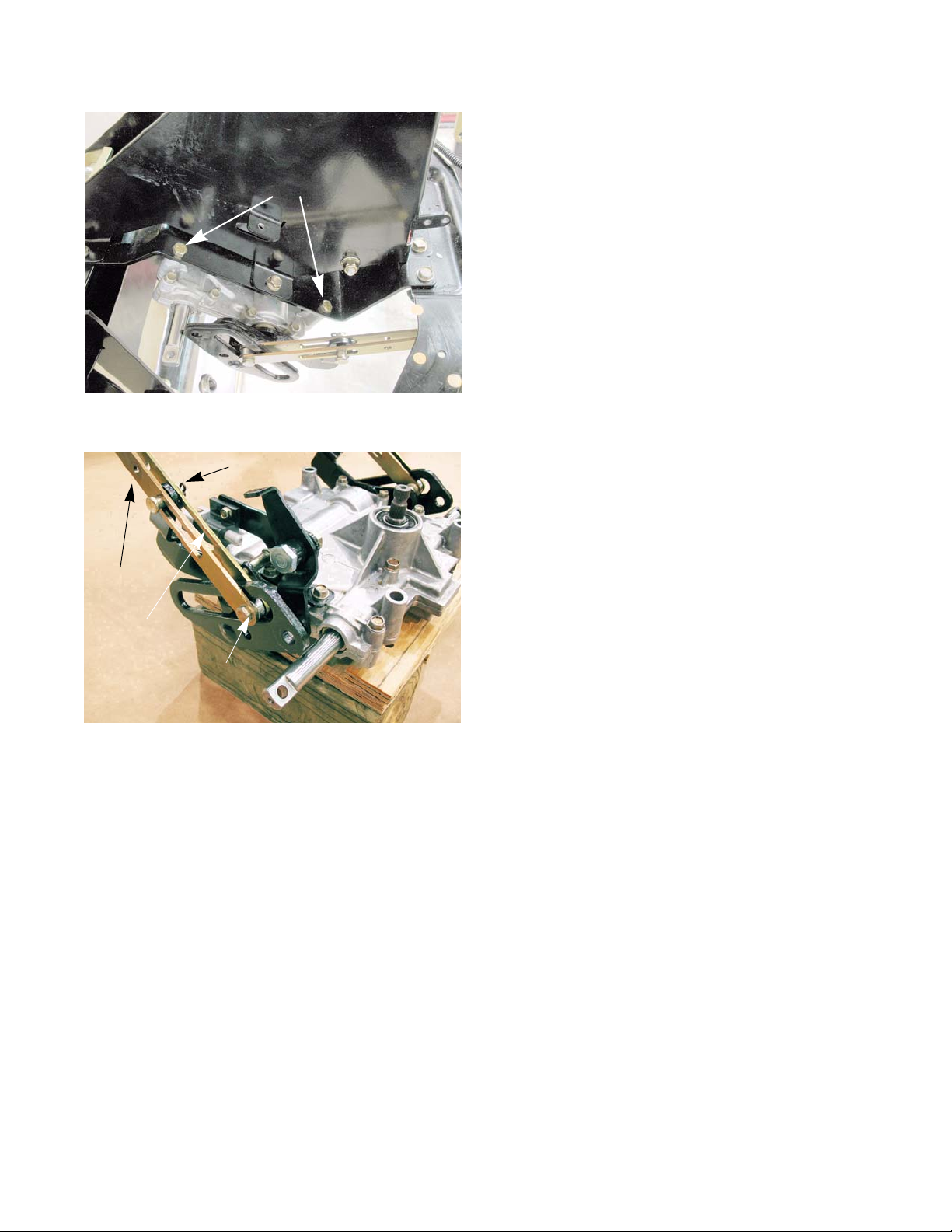
The Z-Force-S uses twin HydroGear transmissions to drive the re ar wheels. The hydrau lic action of the tr ansmissions will provide the braking for the mower while it is in motion. There is a friction brake on the transmission, but it is
used as a parking brake.
NOTE: Mowers equipped with a 48” deck have HydroGear EZT transmissions with the brakes on the inboa rd
side of the transmissions (shown below). Mowers with the 60” deck are equipped with HydroGear
ZT2800 transmissions. The brakes for the ZT2800 transmissions are mounted to the frame of the
mower on the outboard side of the transmissions. The brakes for both the EZT and the ZT2800 trans
missions function and are serviced the same way.
-
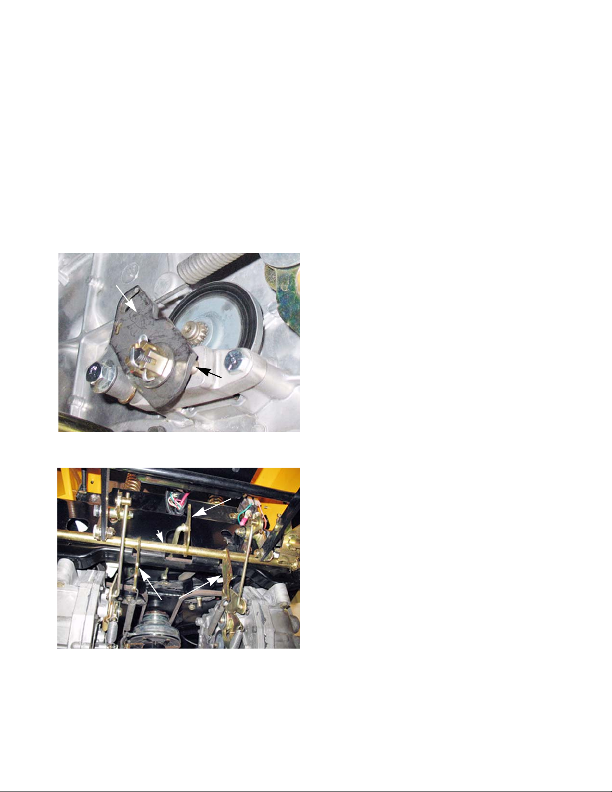
Cam arm
Brake
shaft
Figure 3.1
Brake pins
Center bell
crank
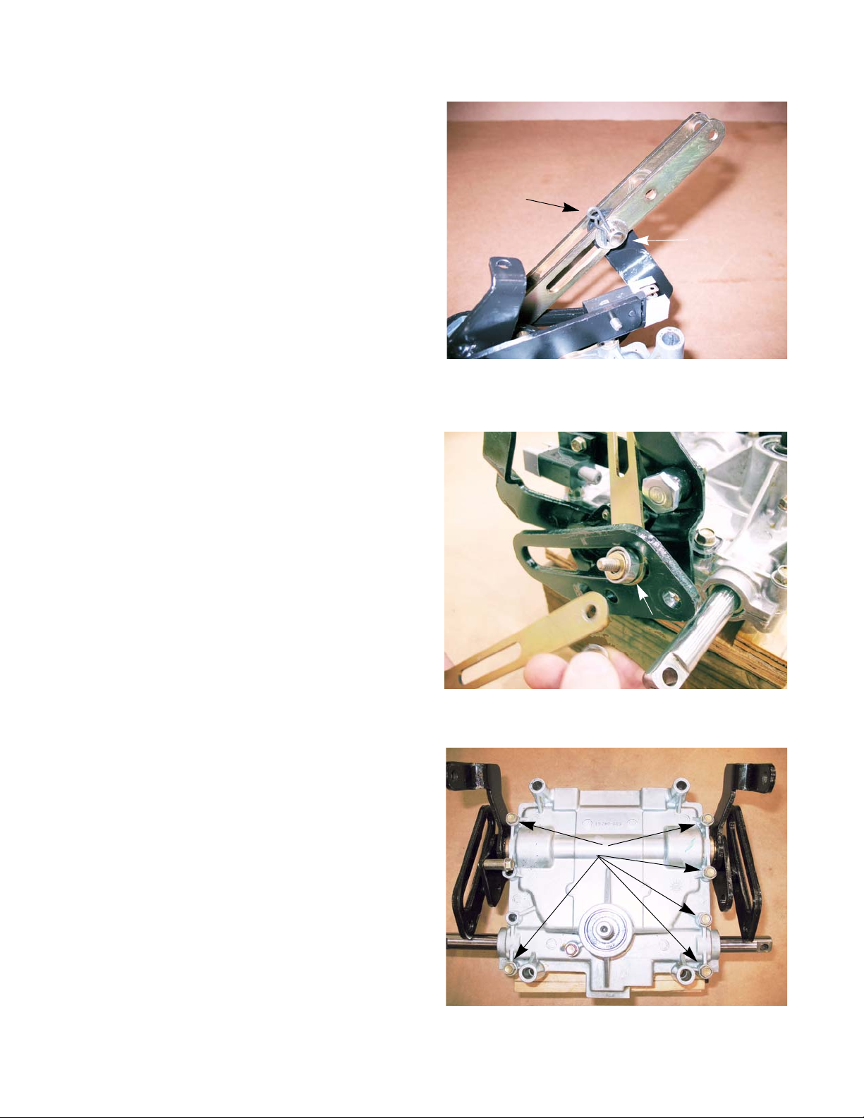
• There is a brake for each transmission.
• They are activated by moving the parking brake
lever to the “ON” position.
• The parking brake lever operates the brake shaft.
• The brake shaft has three bell cranks. The two
outer bell cranks are for applying the brakes. They
are connected to the brake caliper cam arms by
extension springs.
• When the cam arms are pulled forward, they push
on the brake pins with a cam action applying pres
sure to the brake pads. See Figure 3.1.
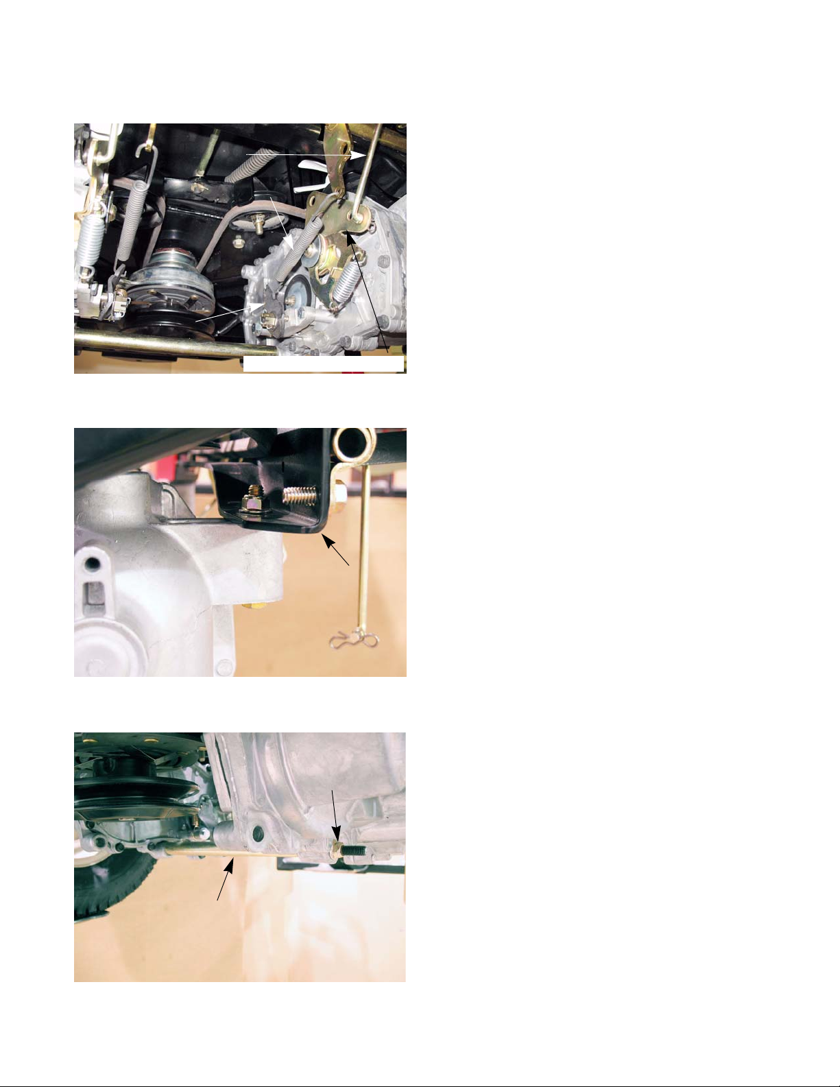
• The center bell crank on the brake cross shaft
assembly has a link that is connected to the drive
belt idler pulley bracket. When the parking brakes
are applied, the idler pulleys are pulled away from
the drive belt. This de-tensions the belt, disengag
ing drive to the transmissions. See Figure 3.2. The
adjustment procedure for the brake link is covered
in the drive belt adjustment section of Chapter 5:
Drive.
-
-
Brake bell
cranks
Figure 3.2
7
Page 14

Z-Force-S
Brake adjustment
NOTE: When performing a brake adjustment, inspect the brake components for signs of wear or damage.
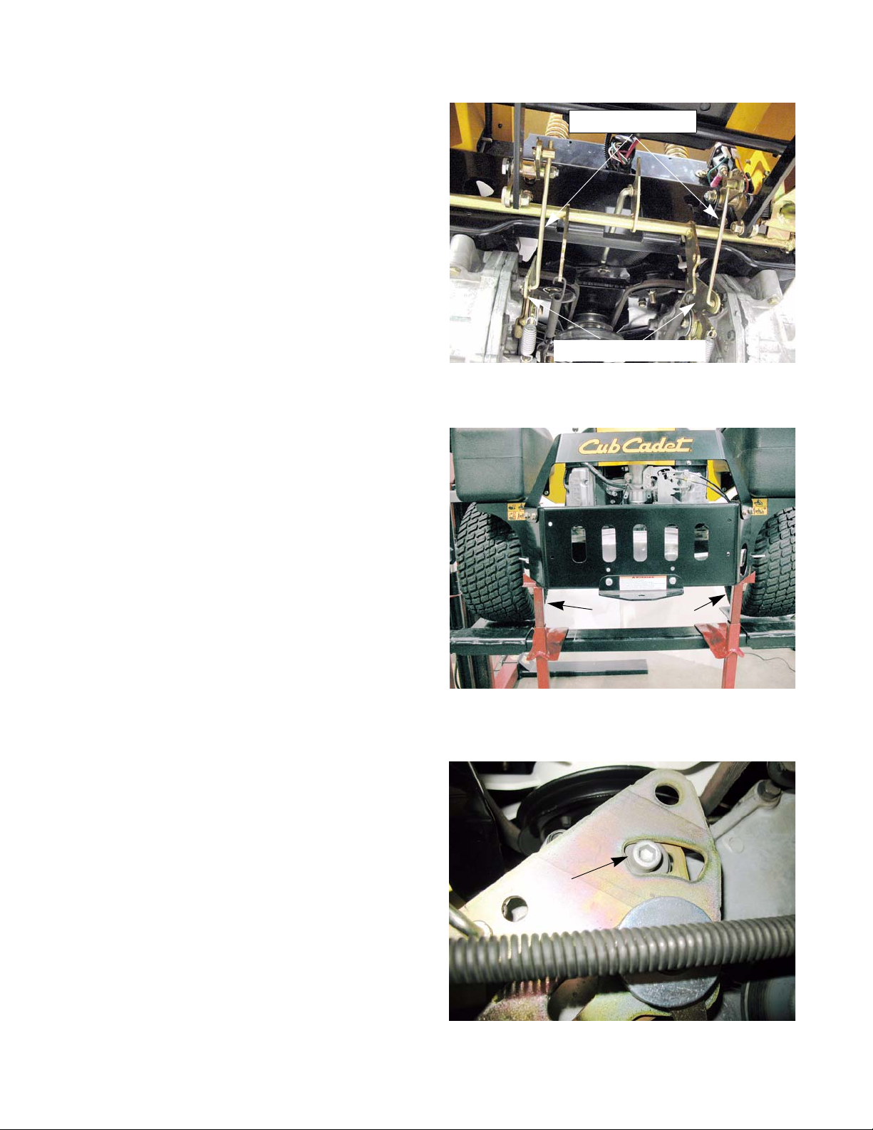
1. Block the front wheels.
2. Lift and safely support the rear of the mower.
NOTE: Make sure the parking brake is released.
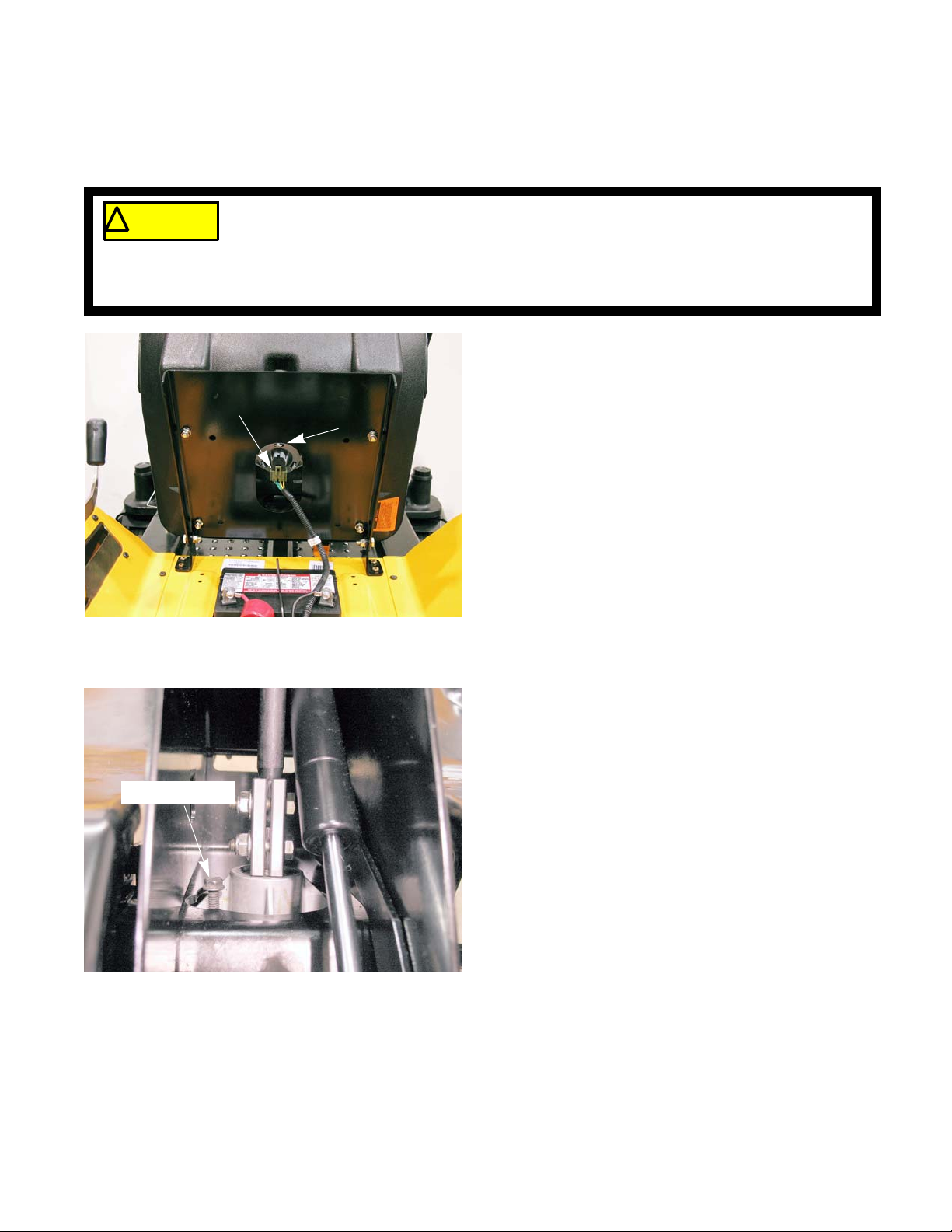
3. Remove the cotter pin locking the castle nut on the
brake caliper.
4. Back the castle nut off a few turns using a 9/16”
wrench.
NOTE: Even if the brakes are set to the correct
5. Insert a 0.030” (0.8 mm) feeler gauge between the
brake rotor and the outboard brake puck.
See Figure 3.4.
NOTE: The tolerance for the brake clearan ce is
See Figure 3.3.
clearance, inserting a feeler gauge between
the rotor and the brake puck can be very dif
ficult. Loosen the castle nut first, then insert
the feeler gauge and tighten the nut to set
the proper clearances
0.020” - 0.040” (0.5 - 1.0mm). The 0.030
feeler gauge will set the clearance at the
midpoint.
Castellated nut
-
Cotter pin
Figure 3.3
6. Tighten the nut un til there is slig ht drag on the feeler
gauge.
NOTE: For even braking, both sides should be set
to the same clearance.
7. Install a new cotter pin.
8. Repeat same procedure on the other side.
9. Take the mower off of the jack stands.
10. Open the by-pass valves and check the parking brake before ret urnin g th e mo we r to serv ice .
• With the brakes released, the mower should have only hydraulic drag when it is pushed.
• With the brakes engaged, the wheels should slide before they rotate when the mower is pushed.
11. Test drive the mower in a safe area before returning it to service.
0.030” feeler
gauge
Figure 3.4
8
Page 15

Brakes
Brake puck/rotor replacement
On HydroGear transmissions, the brake pucks are wearing parts that will need to be serviced from time to time. If
a mower is operated with the parking brake dragging, the pucks will wear out rapidly and the brake rotor will develop
hot spots. If the mower is operated long enough, the rotor may have grinding marks on it with excessively worn
pucks.
! CA UTION! CA UTION
The brake pucks and the rotors are serviced at the same time. To service the brake pucks:
If the rotor shows hot spots or any other signs of damage, including warpage, it must be
replaced. Failure to do so can result in the failure of the brakes
Brake spring
Figure 3.5
1. Lift and safely support the rear of the mower.
2. Make sure the parking brake is released.
3. Disconnect the brake springs. See Figure 3.5.
Loosen this bolt
4. Loosen the rear mounting bolt. See Figure 3.6.
Remove this
bolt
Figure 3.6
9
Page 16

Z-Force-S
5. Remove the front mounting bolt, allowing the caliper
to swing down.
6. The outboard brake puck should fall out when the
brake caliper swings down. If it did not, it can be
removed now.
7. Slide the brake rotor off to reach the inboard brake
puck.
See Figure 3.8.
See Figure 3.7.
Caliper
Figure 3.7
8. Remove the caliper for inspection when servicing
the brake pucks. To do this, remove the rear bolt
loosened in step 4.
9. With the caliper on a work bench, remove the brake
puck, backing plate and the two brake pins.
See Figure 3.9.
10. Check for free movement of the brake pins. A dry
lubricant can be used on the brake pins sparingly.
Never put grease or anti-seize on
! CA UTION! CA UTION
of the pucks.
brake pins. It can migrate to the brake
pucks, preventing the braking action
Inboard brake
puck
Figure 3.8
Brake caliper
Brake pins
Backing plate
11. Slide the brake pins into the caliper.
12. Place the backing plate in the caliper.
10
Brake puck
Figure 3.9
Page 17

Brakes
13. Place a new puck into the caliper. See Figure 3.10.
NOTE: A piece of scotch tape may be used to hold the
new brake pucks in place for assembly. The tape
will grind away when the brakes are applied.
14. Place a new brake puck into the recess in the transmission. Use a piece of scotch tape to hold it in place.
15. Slide the brake rotor in place, shoulder out.
Brake caliper re-assembled
Figure 3.10
19. Repeat steps 4-19 on the other side.
20. When both sides are completed, take the mower off of the jack stands.
21. Open the by-pass valves and check the parking brake before ret urnin g th e mo we r to serv ice .
• With the brakes released, the mower should have only hydraulic drag when it is pushed.
• With the brakes engaged, the wheels should slide before they rotate when the mower is pushed.
22. Test drive the mower in a safe area before returning it to service.
16. Mount the brake caliper to the transmission. Apply a
small amount of releasable thread locking compound
such as Loctite® 242 (blue) to the mounting bolt s and
tighten to a torque of 80 - 120 in-lbs (9 - 13.5Nm).
17. Reconnect the brake spring.
18. Adjust the brakes as described in the previous section of this chapter.
11
Page 18

Z-Force-S
Brake shaft assembly
To remove/replace the brake shaft:
1. Remove the cutting deck by following the procedures described in Chapter 8: Cutting Decks and
Lift shaft.
2. Lift and safely support the rear of the mower.
3. If the parking brake is set, release it.
4. Disconnect the brake springs. See Figure 3.11.
5. Disconnect the link that runs from the idler bracket
to the brake shaft by removing the cotter pin.
See Figure 3.12.
Brake springs
Figure 3.11
Cotter pin
Link
6. Disconnect the adjustable drive links from the pivot
arms by removing the bow tie clips at the ferrule end
of the link.
12
See Figure 3.13.
Figure 3.12
bow tie clip
Adjustable drive
links
Figure 3.13
Page 19

Brakes
Spring
9/16” wrench
3/4” wrench
Figure 3.14
Clamp
Brake lever
Brake shaft
7. Remove the extension spring that runs from the
brake lever to the brake shaft.
8. Remove the nut and shoulder bolt that attaches the
brake lever to the brake shaft using a 9/16” wrench
and a 3/4” wrench.
9. Remove the clamps (one on each side) that hold the
brake shaft to the frame of the mower. Use a 1/2”
wrench.
10. Install the brake shaft by following the previous step s
in reverse order.
See Figure 3.15.
See Figure 3.14.
Figure 3.15
1 1. T est drive the mower in a safe area before returning it
to service.
13
Page 20

Z-Force-S
Parking brake lever
To remove/replace the parking brake lever:
1. Remove the cutting deck by following the procedures described in Chapter 8: Cutting Decks and
Lift shaft.
Spring
2. Move the parking brake lever to the “OFF” position.
3. Remove the extension spring that runs from the
brake lever to the brake shaft.
NOTE: When the parking brake lever is in the “ON”
position, this spring pulls on the lever apply
ing pressure to the parking brake switch.
4. Remove the two screws from the underside of the
left control panel using a T-30 torx driver.
See Figure 3.17.
See Figure 3.16.
Brake lever
Brake shaft
-
Figure 3.16
5. Remove the grip from the parking brake lever.
See Figure 3.18.
6. Remove the two screws that hold the left control
panel to the seat box assembly using a T-30 torx
driver.
See Figure 3.18.
7. Remove the two screws that hold the control panel
to the control pods using a T-30 torx driver.
Left control panel
Figure 3.17
Grip
Screws
Figure 3.18
14
Page 21

Parking brake spring
9/16” wrench
3/4” wrench
Figure 3.19
Brakes
8. Carefully raise the control panel enough to gain
access to the inside of the control pod.
9. Disconnect the spring that runs from the parking
brake lever to the frame of the mower.
See Figure 3.19.
10. Remove the nut and shoulder bolt that attach the
brake lever to the brake shaft using a 9/16” wrench
and a 3/4” wrench.
11. Remove the parking brake lever.
See Figure 3.20.
Figure 3.20
Parking brake lever
Clamp
Plastic bushings
12. Remove and inspect the plastic bushings for signs of
wear or damage.
NOTE: If there are signs of damage or wear, replace the
bushings.
13. Install the parking brake lever by following the previous steps in reverse order.
14. Test drive the mower in a safe area before returning it
to service.
Shoulder bolt
Nylock nut
Figure 3.21
15
Page 22

Z-Force-S
16
Page 23

Floor pan
Body
CHAPTER 4: BODY
Screws
Figure 4.1
Deck lift pedal
Tilt steering pedal
Clevis pin
Spacer
To remove/replace the floor pan:
1. Remove the deck by following the procedures
described in Chapter 8: Decks and Lift Shafts.
2. Remove the two screws that hold the tilt steering
pedal using a T-30 torx driver.
3. Remove the tilt steering pedal.
4. Remove the rear nut, bolt and spacer from the deck
lift indexing bracket using a pair of 9/16” wrenches.
See Figure 4.2.
5. Remove the clevis pin from the deck lift indexing
bracket.
See Figure 4.2.
See Figure 4.1.
Shoulder bolt
Lift pedal arm
Deck lift indexing bracket
Figure 4.2
6. Lower the deck lift pedal.
7. Remove the pedal by removing the shoulder bolt and
nut using a pair of 9/16” wrenches.
NOTE: On mowers equipped with a 60” deck, there are
two lift assist springs. With the deck removed,
these springs will hold the lift pedal arm in the for
ward position with great force.
-
17
Page 24

Z-Force-S
8. Remove the reverse pedal using a 7/16” wrench.
See Figure 4.3.
9. Remove the drive pedal using a 1/2” wrench.
See Figure 4.3.
Drive pedal
Reverse pedal
Figure 4.3
10. Remove the eight screws that hold the floor pan to
the frame using a T-30 torx driver.
NOTE: The two outboard screws next to the seat
box are longer than the rest. They also pass
through a pair of spacers.
11. Lift the floor pan off of the mower.
NOTE: Under the floor pan there are two spacers.
See Figure 4.5.
12. Install the floor pan by following the previous steps
in reverse order.
See Figure 4.4.
Long screw
Long
screw
Figure 4.4
Spacers
18
Figure 4.5
Page 25

Left control console
Body
left control panel
Screws
Figure 4.6
To remove/replace the left side control console:
1. Disconnect the negative battery cable.
2. Remove the deck by following the procedures
described in Chapter 8: Decks and Lift Shafts.
Release the parking brake before
! CA UTION! CA UTION
3. Remove the two screws from the underside of the left
control panel using a T-30 torx driver.
NOTE: Technicians with good dexterity can remove the
RMC module, PTO switch and hour meter with out
removing the left control panel.
• Release the parking brake
• Remove the four screws that hold the park brake
locking plate to the control panel.
• Gentle lower the locking bracket to prevent dam-
age to the parking brake switch.
• Reach into the opening to access the switches.
the control panel.
See Figure 4.6.
Ground cable
Figure 4.7
PTO clutch harness
4. Disconnect the PTO clutch harness. See Figure 4.7.
5. Disconnect the ground cable from the frame.
See Figure 4.7.
19
Page 26

Z-Force-S
6. Disconnect the engine harness from the main harness. See Figure 4.8.
7. Disconnect the starter cable. See Figure 4.8.
8. Remove the grip from the parking brake lever.
See Figure 4.9.
9. Remove the two screws that hold the left control
panel to the seat box assembly using a T-30 torx
driver.
See Figure 4.9.
10. Remove the two screws that hold the control panel
to the control consoles using a T-30 torx driver.
Starter
cable
Engine harness
connector
Figure 4.8
Grip
11. Carefully lift up on the control panel to gain access
to the wiring under it.
12. Disconnect the wiring harness from the switches
and modules.
13. Lift the control panel off of the mower.
NOTE: If the control panel is being replaced,
See Figure 4.10.
remove the switches and modules from it
and install them on the new control panel.
Screws
Figure 4.9
RMC module
Hour meter
Key switch
PTO switch
Figure 4.10
20
Page 27

Lift assist spring
Figure 4.11
Body
14. Disconnect the deck lift assist spring.
See Figure 4.11.
NOTE: The lift assist spring exerts a lot of force.
15. Remove the nuts and bolts that hold the utility bin
bracket to the control console using a pair of 1/2”
wrenches.
See Figure 4.12.
Nuts
1/2” wrench
Figure 4.12
Figure 4.13
Screws
16. Remove the two screws that hold the rear of the control console to the seat box assembly using a T-30
torx driver and a 7/16” wrench.
NOTE: The upper screw goes through a reinforcement
plate for the lift assist spring.
See Figure 4.13.
21
Page 28

Z-Force-S
17. Remove the screws that hold the front of the control
console to the front of the seat box assembly using
a T-30 torx driver and a 7/16” wrench.
4.21.
18. Gently pull the harness through the hole in the console while lifting it off of the mower.
See Figure
19. Install the control console by following the previous
steps in reverse order.
20. Test drive the mower in a safe area before returning
it to service.
Screws
Figure 4.14
22
Page 29

Right control console
right control panel
Choke cable
Throttle cable
Figure 4.15
Body
To remove/replace the right side control console:
1. Disconnect the choke and throttle cables from the
engine.
NOTE: Paint marking and color coding the cables will
NOTE: On mowers equipped with the 60” decks, remove
2. Remove the two screws from the underside of the
right control panel using a T-30 torx driver.
See Figure 4.16.
See Figure 4.15.
make reassembly easier.
the deck by following the procedures described in
Chapter 8: Decks and Lift Shafts.
Screws
Figure 4.16
Right control panel
Screws
Figure 4.17
Seat
box
assembly
3. Remove the two screws that hold the right control
panel to the seat box assembly using a T-30 torx
driver.
See Figure 4.17.
4. Remove the two screws that hold the control p anel to
the control consoles using a T-30 torx driver.
5. Lift the control panel off of the control console.
NOTE: If the control panel is being replaced, remove the
throttle and choke cables from it and install them
on the new control panel.
23
Page 30

Z-Force-S
NOTE: On mowers equipped with a 60” deck, dis-
connect the deck lift assist spring.
6. Remove the nuts and bolts that hold the fuel tank
bracket to the control console using a pair of 1/2”
wrenches.
See Figure 4.19.
Lift assist spring
Figure 4.18
7. Remove the two screws that hold the rear of the
control console to the seat box assembly using a T30 torx driver and a 7/16” wrench.
NOTE: On mowers equipped with a 60” deck, the
upper screw will go through a reinforcement
plate for the lift assist spring.
See Figure 4.20.
1/2” wrenches
Figure 4.19
7/16” wrench
T-30 driver
24
Figure 4.20
Page 31

Body
8. Remove the screws that hold the front of the control
console to the front of the seat box assembly using a
T-30 torx driver and a 7/16” wrench.
9. Lift the control console off of the mower.
See Figure 4.21.
7/16”wrench
10. Install the control console by following the previous
steps in reverse order.
1 1. T est drive the mower in a safe area before returning it
to service.
T-30 torx
Figure 4.21
25
Page 32

Z-Force-S
Seat
To remove/replace the seat:
1. Disconnect the seat switch.
2. Remove the four nuts that hold the seat track to the
seat base using a 1/2” wrench.
3. Lift the seat off of the base.
NOTE: The track is serviced as part of the seat and
is not available separately.
4. Remove the seat switch using a 3/8” wrench.
See Figure 4.23.
5. Install the seat by following the previous steps in
reverse order.
See Figure 4.22.
Nuts
Seat switch
Figure 4.22
Seat switch
6. Test drive the mower in a safe area before returning
it to service.
Figure 4.23
26
Page 33

Seat box assembly
Pivot bolt
Body
Battery
To remove/replace the seat box assembly:
1. Remove the battery and battery box. See Figure 4.24.
2. Disconnect the seat switch.
Figure 4.24
3. Remove the seat pivot bolts. See Figure 4.25.
4. Remove the seat from the mower.
PTO relay
Figure 4.25
Figure 4.26
Starter solenoid
5. Disconnect the fuse holder/PTO relay from the seat
box.
See Figure 4.26.
6. Remove the two screws and nuts that hold the st arter
solenoid to the seat box.
NOTE: The wires do not need to be disconnected. The
solenoid can be left hanging.
7. Remove the left control console by following the procedures described in the left control console section
of this chapter.
8. Remove the right control console by following the
procedures described in the right control console
section of this chapter.
27
Page 34

Z-Force-S
9. Disconnect the reverse switch harness from the
conduit clip on the right side of the seat box.
See Figure 4.27.
10. Remove the four screws (two on each side) that
hold the seat box assembly to the frame using a 1/
2” wrench.
11. Lift the seat box assembly off of the mower.
12. Install the seat box by following the previous steps
in reverse order.
See Figure 4.28.
Reverse switch harness
Figure 4.27
Screws
13. Test drive the mower in a safe area before returning
it to service.
Figure 4.28
28
Page 35

Drive
CHAPTER 5: DRIVE
The Z-Force S is built using two different models of HydroGear transmissions. The 48 ” de ck vers ion is equip ped
with two HydroGear EZT transmissions. The 60” version is equipped with two ZT2800 transmissions.
The Hydro-gear shop manual for the EZT transmissions is form number BLN-52622. The Hydro-gear shop man-
ual for the ZT2800 transmissions is form number BLN-52441. These manuals are available through HydroGear.
Drive belt
The drive belt is the most common drive system component that will need attention. To remove/replace the drive
belt:
NOTE: The procedure to re place the drive belt is the same
for both transmission models.
1. Remove the deck as described in chapter 8: Cutting
Decks and Lift Shaft.
2. Set the parking brake.
3. Lift and safely support the rear of the mower.
Jack stands
Figure 5.1
Figure 5.2
Idler pulleys
4. Remove one of the rear wheels. See Figure 5.1.
5. Loosen the idler pulleys using a pair of 9/16”
wrenches.
6. Slip the belt past the belt guides and off of the idler
pulleys.
See Figure 5.2.
29
Page 36

Z-Force-S
7. Remove the two screws that secure the fan cover to
the frame using a 1/2” wrench.
NOTE: On the mowers equipped with a 60” deck,
the screw on the left side also goes through
the harness clamp.
8. Slide the fan cover out of the mower on the side that
has the tire removed.
9. Remove the transmission fans using a 3/8” wrench.
10. Slide the drive belt off of the transmission pulleys.
See Figure 5.3.
See Figure 5.3. Insert.
Harness clamp
Figure 5.3
11. Unplug the electric PTO harness. See Figure 5.1.
12. Unbolt the electric PTO using an impact wrench and
a 5/8” socket.
NOTE: If the PTO clutch will not slide off of the
NOTE: If the PTO will not come off using the steps
See Figure 5.5.
crankshaft, thread the bolt half way into the
crankshaft. Make sure the belt keeper is in
place to prevent the clutch from rotating.
Star t the engine a nd turn th e P T O on and of f
several times to shake it loose.
above, remove the engine mounting bolts
and slide the engine forward. This will give
enough clearance to slide the belt off of the
engine pulley.
PTO harness
Transmission fans
Figure 5.4
PTO clutch
Figure 5.5
30
Page 37

Drive
Engine pulley
Figure 5.6
Cub Cadet belts are designed to fit our equipment and are not standard lengths. Use of a
! CA UTION! CA UTION
14. The belt can now be snaked out of the mower.
15. Install the belt following the above steps in reverse order.
non-OEM belt may prevent the de-clutching mechanism from working properly when the
brakes are applied.
13. Slide the engine pulley down far enough to slip the
NOTE: Note the direction of the key in the engine pulley. It
NOTE: When installing the engine pulley and electric PT O,
NOTE: If the engine pulley is seized to the crankshaft, the
belt off of the pulley.
should be facing down. If the pulley is installed
upside down, the belt alignment will be off.
coat the crank shaft with anti-seize. This will ease
pulley and clutch removal in the future.
engine bolts can be removed to slid e the engine to
the rear. This will provide enough clearance to
remove the belt.
See Figure 5.6.
NOTE: Tighten the electric PTO clutch bolt to a torque of 450 - 600 in-lbs (51 - 68 Nm).
16. Test dr ive the m owe r befo re returning to service.
31
Page 38

Z-Force-S
Drive belt adjustment
The drive belt is tensioned by a spring loaded idler pulley. When the brakes are applied, the drive belt is declutched. An adjustable linkage connects the tensioning pulley to the brake shaft. A brake link that is out of adjust
ment will prevent the moveable idler from correctly tensioning and de-tensioning the belt.
As the belt wears and stretches, the moveable idler need s to p ush the be lt in furthe r to kee p prop er be lt ten sion.
To do this, the ferrule at the end of the brake link needs to be at the middle of the slot in the idler pulley bracket. To
adjust this brake link:
NOTE: The brake link is properly adjusted when the
belt is fully de-clutched as the brake is
applied and fully tensioned when the brake
is released.
-
NOTE: The belt must be on when performing this
adjustment.
1. Release the parking brake.
2. Remove the deck as described in chapter 8 Cutting
Decks and Lift Shaft.
3. Remove the cotter pin and washer from the ferrule
on the end of the brake link.
4. Slide the ferrule out of the idler bracket.
5. Adjust the ferrule so that it lines up with the middle
of the slot and slides in without pulling on the spring.
See Figure 5.8.
6. Install the washer and a new cotter pin.
7. Test drive the mower before returning to service.
8. Re-attach the deck.
See Figure 5.7.
Tensioning spring
Cotter pin
Brake link
Ferrule
Figure 5.7
Ferrule
32
Figure 5.8
Page 39
EZT transmission removal/replacement
Drive
Bad
Drive control rod
Cam arm
spring
Speed selector plate
Figure 5.9
1. Remove the deck as described in Chapter 8 Cutting
Decks and Lift Shaft.
2. Lift and safely support the rear of the mower.
3. Remove the drive belt by following the procedures
described previously in this chapter.
NOTE: When removing the belt, remove the wheel of the
transmission to be removed.
4. Disconnect the brake rod spring from the cam arm.
See Figure 5.9.
5. Remove the bowtie clips that secure the drive control
rods to the speed selector plates.
6. Slide the rods out of the selector plate.
7. Remove the nut and bolt that hold the front of the
transmission to the frame cross member using a pair
of 1/2” wrenches.
See Figure 5.10.
Figure 5.10
Spacer
Frame cross
member
Nut
8. Remove the nut, T -bolt and spacer that connect the
transmissions to each other.
See Figure 5.11.
Figure 5.11
33
Page 40

Z-Force-S
9. Remove the bolt holding the rear of the transmission to the torque bracket. See Figure 5.12.
10. Support the transmission to prevent it from falling
while the mounting bolts are removed.
11. Remove the two bolts that fasten the transmission
to the frame.
See Figure 5.15.
Torque br acket
Bolt
Figure 5.12
Transmission bolts
12. Lower the transmission enough to gain access to
the by-pass rod.
13. Remove the hair pin clip that secure the by-pass rod
to the by-pass lever.
14. Lift the by-pass rod off of the by pass lever.
15. Remove the transmission from the mower.
16. Install the transmission by following the previous
steps in reverse order.
NOTE: Before lowering the mower to the ground
purge the transmission by:
• Move the by-pass rod to the by-pass position.
• Start the engine.
• Cycle the drive pedal from full forward to full
reverse six times.
• Move the by-pass rod to the drive position.
• Cycle the drive pedal from full forward to full
reverse six times.
17. Perform a neutral adjustment and wheel alignment
by following the steps described in 6: Steering.
18. Test dr ive the m owe r befo re returning it to service.
See Figure 5.14.
Figure 5.13
By-pass rod
Figure 5.14
34
Page 41

ZT 2800 transmission removal/replacement
Jack stands
Figure 5.15
Expansion tank
Drive
1. Remove the deck as described in chapter 8 Cutting
Decks and Lift Shaft.
2. Lift and safely support the rear of the mower.
3. Remove the drive belt by following the procedures
described previously in this chapter.
NOTE: When removing the belt, remove the wheel of the
transmission to be removed.
4. Release the parking brake.
5. Remove the two screws that hold the expansion t ank
to the seat box using a 7/16” wrench.
See Figure 5.16.
6. Follow the vent hose from the transmission to be
removed up to the expansion tank.
Vent h ose
Figure 5.16
Drive control rod
7. Using a pair of pliers, squeeze the tabs on the hose
clamp together while sliding the clamp down the
hose.
8. Carefully remove the vent hose from the expansion
tank.
NOTE: The expansion tank should be empty when the
transmission is cold.
9. Remove the bowtie clip that secures the drive cont rol
rod to the speed selector plate.
10. Slide the rod out of the selector plate.
Speed selector plate
Figure 5.17
35
Page 42

Z-Force-S
11. Remove the nut and bolt that hold th e front of the
transmission to the frame cross member using a
pair of 1/2” wrenches.
12. Remove the nut, T -b olt and spacer that connect the
transmissions to each other.
See Figure 5.18.
See Figure 5.19.
Front transmission
bolt
Figure 5.18
13. Remove the bolt holding the rear of the transmission to the torque bracket. See Figure 5.20.
Spacer
Nut
Figure 5.19
Torque bracket
36
Figure 5.20
Page 43

Drive
Transmission mount
bolts
Figure 5.21
14. Support the transmission to prevent it from falling
while the mounting bolts are removed.
15. Remove the two bolts that fasten the transmission to
the frame.
16. Lower the transmission enough to gain access to the
by-pass rod.
17. Remove the hair pin clip that secure the by-pass rod
to the by-pass lever.
18. Lift the by-pass rod off of the by pass lever.
See Figure 5.21.
See Figure 5.14.
By-pass rod
Figure 5.22
20. Install the transmission by following the previous steps in reverse order.
NOTE: Before lowering the mower to the ground purge the transmission by:
• Move the by-pass rod to the by-pass position.
• Start the engine.
• Cycle the drive pedal from full toward to full reverse six times.
• Move the by-pass rod to the drive position.
• Cycle the drive pedal from full forward to full reverse six times.
NOTE: Removal of the brake caliper will make installing the transmission easier, but is not required.
21. Perform a neutral adjustment and wheel alignment by following the steps described in 6: Steering.
22. Test dr ive the m owe r befo re returning it to service.
19. Remove the transmission from the mower.
NOTE: If replacing the transmission, Inspect the vent
hose. If it is in good condition remove it from the
old transmission and install it on the new transmis
sion. If it cracked, brittle or damaged, install a new
vent hose on the new transmission.
-
37
Page 44

Z-Force-S
Drive pedal biasing adjustment
The Z-Force-S is equipped with a pedal biasing
cam. This cam allows the pedals to be adjuste
increase forward travel speed or reverse travel speed.To
adjust the pedal biasing:
1. Remove the floor pan by following the procedures
described in Chapter 4 Body.
2. Inspect the bushings that support the forward drive
pedal shaft.
NOTE: Any wear in the bushings will affect pedal
See Figure 5.23.
travel. Replace worn bushings before adjust
ing pedal biasing cam.
d to
Forward drive pedal shaft
-
Bushings
Figure 5.23
3. Loosen the biasing cam lock bolt using a 9/16”
wrench while holding the biasing cam with a 3/4”
wrench.
4. Rotate the cam using a 3/4” wrench while watching
the forward drive pedal arm.
NOTE: Adjusting the forward drive arm towards the
front of the mower will give more reverse
pedal travel and less forward pedal travel.
Adjusting the forward drive pedal arm
towards the rear of the mower will increase
forward pedal travel and decrease reverse
pedal travel.
NOTE: When the bolt hole in the biasing cam in at
the top center or bottom center position, The
cam is in the neutral bias position.
ure 5.25.
5. Tighten the biasing cam lock bolt using a 9/16”
wrench while holding the biasing cam in place with a
3/4” wrench.
See Figure 5.24.
See Fig-
More forward
Biasing cam
Neutral biasing position
More reverse
9/16” bolt
forward drive
pedal arm
Figure 5.24
6. Install the floor pan by following the procedures
described in Chapter 4: Body.
7. Test drive the mower in a safe area before returning
it to service.
38
Biasing cam
Figure 5.25
Page 45
Hydro neutral control adjustment
NOTE: Neutral control rarely goes out of adjustment on its own. If it needs adjustment, check for damaged
linkage or signs of tampering.
Drive
! CAUTION! CAUTION
• Work in a well vented area to prevent carbon monoxide poiso ning or asphyxiation.
• Be careful to avoid contact with hot parts or moving parts.
Seat safety switch
The mower engine and drive system must be operated to complete this procedure. Confirm
that no hazards will be incurred by running the engine or operating the drive system.
To perform the hydro neutral control adjustment:
NOTE: The procedure to perform the hydro neutral contro l
adjustment is the same for the ZT 2800 and the
Tang
1. Lift and safely support the rear of the mower.
2. By-pass the seat safety switch. See Figure 5.26.
Figure 5.26
EZT transmissions.
2a. Slide the seat to the full forward position.
2b. Flip the seat up.
2c. Press in the seat bottom until the tang on the
seat switch is fully extended.
2d. Place a spring clamp on the tang to hold the
seat switch in this position.
Locking screw
Figure 6.27
3. Remove the four screws that hold the steering column cover in place using a T-30 torx driver.
4. Lock Steering Gear Box in Neutral Position:
4a. Remove the 1/4”-20 plug screw from the steer-
ing gear box centering port using a 3/8” wrench.
See Figure 6.27.
4b. Thread a 1/4”-20x2” bolt into the steering box
centering port until you feel it touch the steering
rack.
4c. Wh ile tr ying t o gent ly thr ea d the bo lt fu rth e r,
slowly rotate the steering shaft back and forth
until the bolt seats into the detent in the steering
rack.
4d. Finger tighten the screw to set the screw fully
into the detent. The steering gear box is now
centered and locked.
39
Page 46
Z-Force-S
5. Disconnect both of the drive control arms from the
speed selector plates.
6. Start the engine and advance throttle to maximum
RPM.
7. Release the parking brake.
8. Watch both rear tires for movement.
See Figure 5.29.
See Figure 5.28.
Drive control rods
Speed selector plates
Figure 5.28
NOTE: If there is no wheel movement, the hyrdo
transmissions are in neutral and don’t need
to be adjusted. Skip ahead to step 13.
NOTE: If one or both rear wheels move, the hydro
transmissions need to be adjusted. Continue
on to step 9.
9. With the engine still running, locate the socket head
cap screw in the slot of the speed selector plate on
the transmission that needs to be adjusted.
10. Loosen the socket head cap screw using a 1/4” hex
key.
See Figure 5.30.
1 1. Adjust the speed selector plate until the wheel stops
moving.
12. Tighten the socket head cap screw using a 1/4” hex
key.
13. Turn-off the engine.
No movement
Figure 5.29
socket head
cap screw
40
Figure 5.30
Page 47

Drive
14. Adjust the drive control rods so they slide freely into the hole in the selector plate. Inst all the hairpin clips.
15. Remove the spring clamp from the seat switch.
16. Lower the mower to the ground.
17. Test the drive system and all safety features before retur nin g the unit to se rvice.
41
Page 48

Z-Force-S
42
Page 49

Steering
CHAPTER 6: STEERING
Introduction
The steering on the Z-Force-S mower works in two phases.
• First it will steer like any other riding mower by turning the front wheels.
• Second and more importantly, the steering linkage will control the drive output of the rear wheels through
the use of two HydroGear transmissions.
The steering gear box is connected to the front wheels by tie rods. When the steering wheel is turned, the gear
box will turn the front wheels. The gear box will also slow the drive speed of the rear wheels. The inside wheel is
slowed more than the outside wheel. When the insi de front wheel reaches an an gle of 90
will stop driving. Turning the wheel past that point will make the inside rear wheel go in reverse. The inside front
wheel can reach a 108
o
angle with the transmission on the inside of the turn driving in reverse. The riding mower will
then make a zero radius turn.
Because the steering gear box is linked to the transmissions, the transmission adjustments and the wheel alignment must be done together. A transmission that is out of adjustment can make the steering look out of adjustment
just as a steering linkage that is out of adjustment will affect the transmissions.
IMPORTANT: Check the tire air pressure and wear before attempting to diagnose any problems with the steer-
ing or tracking of a Z-Force-S riding mower. If the tires are not equal across the same axles, it
will greatly affect the performance of the riding mower.
o
, the rear wheel on that side
IMPORTANT: All zero turn mowers must have matching tires across the same axle (both front wheels and
both back wheels).
Wheel alignment and drive control lin k adj ustments
The wheel alignment and transmission link adjustment are performed together on the Z-force S.
1 Remove the four screws that hold the steering col-
umn cover in place using a T-30 torx driver.
See Figure 6.1.
Screws
Figure 6.1
43
Page 50

Z-Force-S
2. Lock Steering Gear Box in Neutral Position:
2a. Remove the 1/4”-20 plug screw from th e
steering gear box centering port using a 3/8”
wrench.
2b. Thread a 1/4”-20x2” bolt into the steering box
centering port until you feel it touch the steer
ing rack.
2c. While trying to gently thread the bolt further,
slowly rotate the steering shaft back and forth
until the bolt seats into the detent in the steer
ing rack.
2d. Finger tighten the screw to set the screw fully
into the detent. The steering gear box is now
centered and locked.
3. Remove the hairpin clips that secure the drive control rods to the speed selector plates.
See Figure 6.3.
See Figure 6.2.
Locking screw
-
-
Figure 6.2
4. Slide the rods out of the selector plate.
5. Insert two 5/16” pins through th e ho les in the axle
castings. The pins should pass through the casting
down to the wheel yokes.
NOTE: If both pins slide in, the wheels are aligned;
go to step 12. If one or both pins do not slide
in, proceed to the next step.
NOTE: The pins should slide in and out without
binding. As the drag links are being
adjusted, rock the tires back and forth to
remove the load created from the tires twist
ing on the floor.
See Figure 6.4.
Drive control links
Speed selector plates
Figure 6.3
5/16” pin
-
44
Figure 6.4
Page 51

Steering
Figure 6.5
Straight edges
NOTE: The flat side of the yoke should be parallel to the
box section of the frame when the pins are
installed.
NOTE: A couple of straight edges can be used to check
the alignment of the yoke to the frame.
See Figure 6.5.
If they are not:
• Check for a bent yoke.
• Remove the yoke and check the gear timing. See
the yoke section of this chapter for the proper pro
cedures.
6. Loosen the jam nuts on both ends of the tie rod(s).
See Figure 6.6.
See Figure 6.5.
-
Jam nuts
Figure 6.6
7. Disconnect one end of the tie rod. See Figure 6.7.
8. Manually move the front wheel yoke until the alignment holes line up.
9. Insert the 5/16” pin.
Tie rod
end
Figure 6.7
45
Page 52

Z-Force-S
10. Adjust the tie rods until the ends line up with their
mounting point.
11. Re-attach the tie rod(s).
12. Tighten the jam nuts.
13. Adjust the drive control rods so they slide freely into
the hole in the selector plate. Install the hairpin clips.
14. Remove the 1/4”-20x2” screw from the steering
gear box.
15. Reinstall the original plug screw in the steering gear
box.
16. Install the steering column cover.
17. Remove the 5/16” pins.
18. Test drive the riding mower in a safe area before
returning it to service.
See Figure 6.8.
Mounting point
Figure 6.8
46
Page 53

Steering gear box removal
Steering shaft
coupler
Locking screw
Figure 6.9
Steering
To remove/replace the gear box:
1 Remove the deck by following the procedures
described in Chapter 8: Decks and Lift Shaft.
2. Remove the floor pan by following the steps
described in Chapter 4: Body/Chassis.
3. Remove the four screws that hold the steering column cover in place using a T-30 torx driver.
4. Loosen the top clamp bolt in the steering shaft coupler using a pair of 1/2” wrenches.
5. Remove the bottom bolt in the steering shaft coupler .
See Figure 6.9.
NOTE: The clamp bolts pass through grooves in the steer-
ing shaft and the steering gearbox input shaft.
NOTE: It is not necessary to lock the steering gearbox for
removal, but it will need to be centered and locked
for installation.
Return to neutral spring
Figure 6.10
Pedal biasing cam
6. Disconnect the return to neutral spring.
See Figure 6.10.
NOTE:
7. Disconnect the front side of the drive input link using
a 9/16” wrench and a 15/16” wrench.
See Figure 6.11.
NOTE: The rear end of the drive input link is attached to
the drive pedal shaft by a pedal biasing cam.
Removing it will change the pedal travel.
Figure 6.11
Drive input link
47
Page 54

Z-Force-S
8. Disconnect both of the tie rods from the steering
gearbox using a pair of 1/2” wrenches.
See Figure 6.12.
NOTE: There is a spacer between the tie rod end
and the steering rack.
NOTE: The bolt has a special tapered shoulder. Do
not replace it with a standard bolt.
9. Disconnect the reverse switch. See Figure 6.13.
Spacer
Tie rod end
Figure 6.12
10. Disconnect both of the drive control links by removing the nuts and bolts that attach the connector
plates to the drive control link using a pair of 7/16”
wrenches.
See Figure 6.14.
Reverse switch
Figure 6.13
Connector plate
48
Drive control link
Figure 6.14
Page 55
Gear box mounting bolts
Figure 6.15
hairpin clip
Steering
11. Remove the four nuts and bolts (two on each side)
that hold the gearbox to the frame using a pair of 1/
2” wrenches.
12. Lower the steering gearbox out of the mower, sliding
it out of the steering shaft coupler.
NOTE: If replacing the gearbox:
13. Remove the drive control connector plates by:
See Figure 6.15.
Connector
plate
Reverse
switch
Roller
Figure 6.16
13a. Remove the cotter pins, washers and clevis
pins in the linkages.
13b. Remove the nuts and bolts connecting the
transmission linkage s to th e le vers o n t he st eer
ing gear box.
NOTE: There are rollers in the slots. Take care not to lose
them when removing the bolts.
14. Remove the reverse switch.
See Figure 6.16.
-
49
Page 56

Z-Force-S
Steering gearbox installation
1. Attach the drive control link connector plates to the
steering gearbox.
2. Install the reverse switch.
3. Lock the steering gearbox in the cente r ed pos ition :
3a. Remove the 1/4”-20 plug screw from the
steering gear box centering port using a 3/8”
wrench.
See Figure 6.17.
See Figure 6.18.
hairpin clip
Reverse
switch
Connector
plate
Roller
Figure 6.17
3b. Thread a 1/4”-20x2” bolt into the steering box
centering port until you feel it touch the steer
ing rack.
3c. While trying to gently thread the bolt further,
slowly rotate the input shaft back and forth
until the bolt seats into the detent in the steer
ing rack.
3d. Finger tighten the screw to set the screw fully
into the detent. The steering gear box is now
centered and locked.
4. Remove the hairpin clips that secure the drive control links to the speed selector plates.
See Figure 6.19.
5. Slide the rods out of the speed selector plates.
Locking screw
-
Figure 6.18
50
Drive control rods
Figure 6.19
Page 57

5/16” pin
Axle casting
Figure 6.20
Steering
6. Insert two 5/16” pins through the holes in the axle
castings. The pins should pass through the casting
down to the wheel yokes.
NOTE: The flat side of the yoke should be parallel to the
box section of the frame when the pins are
installed.
See Figure 6.21.
See Figure 6.20.
Figure 6.21
Center the steering wheel
The yoke is parallel
to the frame
If they are not:
• Check for a bent yoke.
• Remove the yoke and check the gear timing. See
the yoke section of this chapter for the proper pro
cedures.
7. Center the steering wheel. See Figure 6.22.
-
Figure 6.22
51
Page 58

Z-Force-S
8. Lift the steering gearbox into the frame while sliding
the gearbox input shaft into the steering shaft cou
pler. See Figure 6.23.
9. Install the four mounting nut s and bolt s. T ighten to a
torque of 17 ft lbs (23 Nm).
10. Install the lower coupler bolt.
11. Tighten both coupler bolts to a torque of 72 in lbs (8
Nm).
NOTE: Once the steering gearbox is mounted, the
locking screw can be backed out to allow the
steering shaft to be rotated for easier access
to the coupler bolt. The steering gearbox
must be locked again once the coupler bolts
are torqued.
12. Attach the tie rods to the steering rack.
See Figure 6.24.
-
coupler bolts
Figure 6.23
NOTE: The spacer must be between the tie rod end
and the steering rack.
NOTE: If necessary, adjust the tie rod ends so that
the hole in the rod end lines up with the hole
in the steering rack.
13. Remove the 5/16” pins.
14. Attach the front side of the drive input link using a 9/
16” wrench and a 15/16” wrench.
NOTE: If the pedal biasing cam was moved, the
drive pedal adjustment will need to be per
formed by following the steps described in
the drive pedal adjustment section of Chap
ter 5: Drive System.
See Figure 6.25.
-
Spacer
Figure 6.24
Pedal biasing cam
-
52
Drive input link
Figure 6.25
Page 59

Steering
Return to neutral spring
Figure 6.26
Reverse switch
15. Install the return to neutral spring. See Figure 6.26.
16. Connect the reverse switch. See Figure 6.27.
Figure 6.27
Figure 6.28
Connector plate
Drive control link
17. Connect both of the drive control links by installing
the nuts and bolts that attach the connector plates to
the drive control link using a pair of 7/16” wrenches.
See Figure 6.28.
18. Adjust the drive control links so they slide freely into
the hole in the selector plate. Install the hairpin clips.
19. Remove the locking bolt from the steering gearbox,
and install the plug screw.
20. Install the floor pan by following the steps described
in Chapter 4: Body/Chassis.
21. Install the steering column cover.
22. Test drive the riding mower in a safe area before
returning it to service.
23. Install the deck.
53
Page 60
Z-Force-S
Rebuilding the steering gear box
To take the steering gear box apart:
1. Remove the steering gear box by following the procedures described in the previous section of this
chapter.
2. Remove the drive control link connector plates:
2a. Remove the hairpin clip and clevis pin.
See Figure 6.29.
2b. Remove the nut, while leaving the bolt in
place.
Hairpin clip
Clevis pin
Figure 6.29
2c. Remove the connector plate on the nut side.
2d. Remove the bolt, washers and the roller with
the other connector plate.
3. Remove the brackets from the steering gearbox
using a 3/8” wrench.
4. Remove the six remaining case screws using a 3/8”
wrench.
See Figure 6.31.
See Figure 6.30.
Roller
Figure 6.30
Screws
54
Figure 6.31
Page 61

Using one of the pry
points to separate the
housings
Figure 6.32
Steering
5. Lift the upper housing off of the lower housing.
NOTE: There is no sealant between the two housings.
They should easily slip apart. If they are stuck
together, there are three pry points cast into the
housings that can be used to separate the hous
ings. See Figure 6.32.
6. Remove the steering rack. See Figure 6.33.
-
Wear block
7. Remove the wear block and spring.
Steering
rack
Figure 6.33
8. Remove the speed cam assemblies.
See Figure 6.34.
Speed cam assemblies
Figure 6.34
55
Page 62

Z-Force-S
9. Separate the speed cam assemblies by driving out
the two roll pins using a 5/32” pin punch and a ham
mer. See Figure 6.35.
10. Slide the output bevel gear assemblies off of the
speed cams.
NOTE: Marking the left and right speed cams and
See Figure 6.36.
the left and right hydro arms will make reas
sembly easier.
-
-
5/32” pin punch
Figure 6.35
Output bevel gear assembly
11. Separate the output bevel gear assembly by removing the snap ring. See Figure 6.37.
Hydro arm
Speed cam
Figure 6.36
Remove this snap ring
Figure 6.37
56
Page 63

Input sector
gear
Inspect the
bushings
Figure 6.38
Steering
12. Remove the input sector gear. See Figure 6.38.
NOTE: Some gearboxes were built with a spring washer
on top of the sector gear . If the sector gear is being
replaced, discard the spring washer.
13. Inspect the input sector gear bushings for damage
and/or signs of wear. If they show signs of wear or
damage, press both of the bushings out of th e inp ut
sector gear using a press. Then install new bush
ings. See Figure 6.39.
-
Figure 6.39
Thick washer
Figure 6.40
14. Remove the thick washer. See Figure 6.40.
57
Page 64

Z-Force-S
15. Remove the internal cam and the thin washer.
See Figure 6.41.
16. Remove both of the bevel gears and the washer on
the steering shaft.
See Figure 6.42.
Thin washer
Figure 6.41
Bevel gears
Internal cam
17. Remove the snap ring from the input shaft.
See Figure 6.43.
Washer
Snap ring
Steering
shaft
Figure 6.42
58
Figure 6.43
Page 65

Input shaft
Figure 6.44
Drive out the inner bearing
Steering
18. Remove the input shaft from the inside of the housing. See Figure 6.44.
19. Inspect the bearings. If they are worn or rough, carefully drive the inner bearing out of the upper housing
using a pin punch and hammer.
See Figure 6.45.
Figure 6.45
Figure 6.46
Outer
bearing
20. Drive the outer bearing out of the up pe r ho u sin g
using a pin or brass punch and hammer.
See Figure 6.46.
21. Thoroughly clean and degrease all parts.
22. Inspect all parts for signs of wear or damage.
NOTE: If the part has signs of wear or damage; discard
the part.
NOTE: If the two bushings in the bottom of lower ge ar bo x
housing are worn, replace the lower housing and
press in two new bushings.
59
Page 66

Z-Force-S
To assemble the steering gear box:
1. Put a dab of 737-0300A Durina
of the bushings in the lower housing.
See Figure 6.47.
2. Install both of the bevel gears with the rollers in-line
with the steering shaft.
See Figure 6.48.
TM
grease into each
Put a dab of grease
in each bushing
Figure 6.47
3. Install the washer on the steering shaft.
4. Place the thick washer over the splines on the sector gear. See Figure 6.49.
5. Place the thin washer on top of the thick washer.
6. Insert the sector gear into the internal cam.
NOTE: There is a master spline on the sector gear
and the internal cam to ensure correct tim
-
ing. See Figure 6.49.
Rollers in line with the
steering shaft
Figure 6.48
Master spline
60
Figure 6.49
Page 67

Steering
Figure 6.50
7. Apply a dab of 737-0300A Durina
TM
grease to the
side of the steering shaft.
8. Install the internal cam so that the rollers on the
bevel gears fit inside the groves on the underside of
the cam.
See Figure 6.50.
9. Center the cam so that the hole in the sector gear
lines up with the center of the void where the wear
block goes.
See Figure 6.51. right inset.
NOTE: A wooden block can be used to hold the cam in
place while timing the internal components. The
measurements of the block should be 27/32” wide
x 1.5” long. The height should be at least a 1/2”.
See Figure 6.51.
1.5”
Wave washer
Bushing
Figure 6.51
Output bevel gear
Bushing flange
Hydro arm
Figure 6.52
27/32”
Chamfer
NOTE: Putting a screw in the top of the block makes it
easier to remove and prevents closing the box with
the block still inside.
See Figure 6.51. left inset.
10. Re-assemble the output bevel gear assemblies.
10a. Place a bushing over the hydro arm with the
flange facing away from the arm.
See Figure 6.52.
10b. Place the wave washer over the hydro arm.
See Figure 6.52.
10c. Place the output bevel gear on the hydro arm
with the chamfer facing away from the hydro
arm.
See Figure 6.52.
NOTE: If the output bevel gears are put on backwards it
will throw off the timing of the gearbox.
61
Page 68

Z-Force-S
NOTE: The hydro arms and output be ve l gears
have master splines to time them to each
other.
See Figure 6.53.
10d. Install the snap ring.
10e. Repeat for the right output bevel gear assem-
bly.
10f. Slide the bevel gear assemblies onto the
speed cam assemblies.
11. Place both output bevel gear assemblies on the
bench, facing each other . With both assemblies
resting on the same points of the speed cam, insert
both shafts into the coupler.
See Figure 6.54.
Master spline
Figure 6.53
12. Drive the roll pins through the coupler and the shaf ts
to hold the assembly together.
NOTE: The top of the roll pins (as they sit in the
steering gearbox) must be flush with the
coupler or they will bind against the gearbox
cover.
13. Insert the speed cam assemblies in the low er hou sing.
• Align the hole in the input sector gear with the
center of the square recess at the front of the
lower housing. See Figure 6.55.
NOTE: The wooden block from step 9 will hold the
cam in place.
• The bevel gears should face away from the
input sector gear.
• The first tooth of each output bevel gear should
rest in the first valley of the bevel gears in the
bottom of the lower housing. See Figure 6.55.
inset.
Coupler
Both speed cam are in line
Figure 6.54
NOTE: If one or both of the output bevel gears are
out of time, the steering rack will lose travel
on the affected side
62
Figure 6.55
Page 69

Figure 6.56
Steering
14. Fill the lower housing with 12 oz. of 737-0300A Duri-
TM
na
grease. See Figure 6.56.
15. Install the steering rack and bushings.
See Figure 6.57.
Input shaft
Figure 6.57
NOTE: The rack must be centered. When centered, the
rack will measure 1.7” from the shoulder to the
housing.
See Figure 6.57. inset
IMPORTANT: Before proceeding, test fit the input shaft
into the ball bearings for the cover. The input shaft
needs to have a slip fit. If it is too tight, clean the
shaft with some emery cloth.
16. Install the input shaft so that it is centered with the
hole in the sector gear and the center of the void for
the wear block.
See Figure 6.58.
Figure 6.58
63
Page 70

Z-Force-S
17. Install the wear block and spring. See Figure 6.59.
NOTE: The groove in the wear block faces the bot-
tom of the gearbox housing.
18. Press in the upper ball bearing into the upper housing. See Figure 6.60.
Wear block
Figure 6.59
19. Press the lower ball bearing into the upper housing.
See Figure 6.61.
Press in the upper
ball bearing
Figure 6.60
A socket can
be used to press
in the ball bearing
Figure 6.61
64
Page 71

Steering
NOTE: If used, remove the wooden block first.
20. Lower the gearbox cover straight down over the
input shaft.
NOTE: Removal of the screw and spacer on the right
speed cam assembly may help.
IMPORTANT: DO NOT force or hammer the cover over
the input shaft. That will cause the input shaft to
damage the internal cam. If the fit is tight, clean the
shaft with emory cloth and try again.
The cover does not
sit flush with the bottom
Figure 6.62
Putty knife
Figure 6.63
NOTE: The cover will not sit flush with the bottom housing.
21. Using a putty knife or something similar, compress
the spring into the wear block while gently pressing
down on the cover.
22. While holding the cover in place, test the rack fo r fu ll
range of travel in both directions.
22a. Turn the input shaft until the steering rack has
moved all the way to the left. The right shoul der
should be flush with the housing.
22b. Turn the input shaft until the steering rack has
moved all the way to the right. The left shoul der
should be flush with the housing.
See Figure 6.63.
Perimeter screws
Figure 6.64
23. Install the six perimeter screws using a 3/8” wrench.
See Figure 6.64.
65
Page 72

Z-Force-S
24. Install the snap ring on the input shaft.
See Figure 6.65.
25. Install the return to neutral bracket.
Snap ring
Figure 6.65
Reverse switch
26. If the screw and spacer was removed from the
speed cam assembly, re-install it.
27. Center the rack and thread a 1/4”-20x2” bol t into the
hole in the gear box to lock the gear box in neutral.
28. Install the steering gear box in the mower by following the procedures described in the steering gearbox installation section of this chapter.
29. Test drive the riding mower in a safe area before
returning to service.
Return to neutral
bracket
Figure 6.66
66
Page 73

Front wheels
Axle bolt
Figure 6.67
Steering
Remove/ replace the front wheels:
1. Lift and safely support the front end of the riding
mower.
2. Remove the axle bolt and nut using a pair of 3/4”
wrenches.
See Figure 6.67.
Short spacer
Figure 6.68
Short spacer
3. Slide the tire and wheel assembly out of the yoke.
See Figure 6.68.
NOTE: There is a short spacer on each side of the wheel.
The short spacers slide over the long spacer that
the axle bolt passes through.
4. Slide the long spacer out of the wheel bearings.
NOTE: The long spacer is a tight fit to the bearing and may
need to driven out with a hammer and a brass
punch.
5. Install the front wheel by following the previous steps
in reverse order.
Long spacer
Figure 6.69
67
Page 74

Z-Force-S
To replace the front wheel ball bearings:
1. Lift and safely support the front end of the riding
mower.
2. Remove the front wheel by following the procedures
describe in the previous section of this chapter.
3. Drive the bearings out of the wheel hub using a drif t
or pin punch.
4. Drive in the new bearings using a brass punch or a
tube that has the same O.D. as the bearing.
See Figure 6.71.
5. Install the front wheel.
6. Pump grease in the grease fitting on the front wheel
until it starts to squirt out of the hub.
7. Test drive the riding mower before returning it to service.
See Figure 6.70.
Ball bearing
Figure 6.70
Brass punch
68
Figure 6.71
Page 75

Front yokes
Steering
Yoke cover
Figure 6.72
Hex screw
To remove/ replace the front yokes:
1 Lift and safely support the front of the riding mower.
2. Remove the front wheel by following the procedures
in the front wheel section of this chapter.
3. Pry the yoke cover off using a suitable prying tool.
See Figure 6.72.
4. Align the hole of the inboard steering gear with the
hole in the axle casting.
5. Slide a 5/16” lock pin or a pin punch through the hole
in the axle casting all the way through the inboard
steering gear.
5/16” pin
punch
Wave washer
Figure 6.73
6. Remove the hex screw using a 9/16” wrench.
See Figure 6.73.
NOTE: The yoke will slide out as the screw is removed.
7. Remove the washers from the top of the axle casting.
NOTE: If replacing the yoke, remove the steering gear by
following the procedures described in the ste er ing
gear section of this chapter.
To install the yoke:
8. Slide the yoke into the axle casting from the underside.
NOTE: The flat side of the yoke should be parallel with the
box section of the frame.
9. Slide the wave washer over the yoke shaft.
See Figure 6.74.
Figure 6.74
69
Page 76
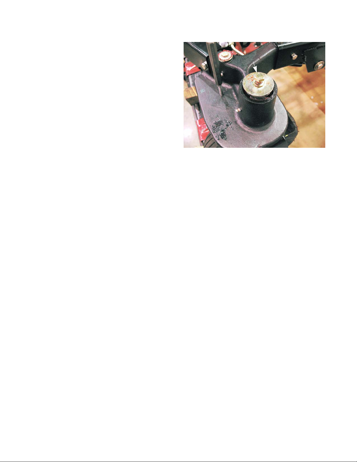
Z-Force-S
10. Install the hex screw with a lock washer and the
fender washer.
11. Tighten the hex screw holding the yoke to a torque
of 31 ft lbs (42 Nm).
12. Install the yoke cover.
13. Install the front wheel by following the procedures
described in the front wheel section of the chapter.
14. Test drive the riding mower in a safe area before
returning it to service.
See Figure 6.75.
Hex screw
Figure 6.75
70
Page 77

Removal of the steering gears
Screws
Figure 6.76
Steering
To remove the steering gears:
1 Remove the four screws that hold the steering col-
umn cover in place using a T-30 torx driver.
See Figure 6.76.
locking screw
“LH” Stamped
into gear
Figure 6.77
socket headed
cap screw
2. Lock the steering gearbox in the centered position:
2a. Remove the 1/4”-20 plug screw from the steer-
ing gear box centering port using a 3/8” wrench.
See Figure 6.77.
2b. Thread a 1/4”-20x2” bolt into the steering box
centering port until you feel it touch the steering
rack.
2c. Wh ile tr ying t o gent ly thr ea d the bo lt fu rth e r,
slowly rotate the steering shaft back and forth
until the bolt seats into the detent in the steering
rack.
2d. Finger tighten the screw to set the screw fully
into the detent. The steering gear box is now
centered and locked.
3. Remove the floor pan by following the steps
described in Chapter 4: Body/Chassis.
4. Remove the yoke by following the procedures
described in the previous section of this chapter.
5. Remove the socket headed cap screw that holds the
outboard steering gear to the yoke using a 1/4” hex
key.
See Figure 6.78.
NOTE: The same gear is used on both yokes. One side is
used for the left and it is flipped over for the right.
Mark the hole in the yoke that the screw was
removed from to help ensure proper orientation
when installing the gear.
See Figure 6.78.inset.
Figure 6.78
6. Slide the gear off of the yoke.
71
Page 78

Z-Force-S
7. Loosen the jam nuts on both ends of the tie rod(s).
See Figure 6.79.
8. Disconnect the tie rod end from inboard steering
gear using a pair of 1/2” wrenches.
See Figure 6.80.
Jam nuts
Figure 6.79
Inboard steering
gear
9. Remove the hex screw and washer from the top
side of the inboard steering gear shaft in place using
a 1/2” wrench.
NOTE: A 5/16” lock pin or pin punch can be used to
lock the inboard steering gear, unless the
gear is broken.
10. Slide the inboard steering gear shaft out of the axle
casting.
72
See Figure 6.81.
Figure 6.80
Hex screw
Figure 6.81
Page 79

Steering gear shaft
Steering gear
Figure 6.82
Hex screw
Steering
11. Remove the hex screw that holds the steering gear
to the shaft using a 9/16” wrench.
12. Slide the steering gear off of the shaft.
NOTE: The shaft has a double-D. It may be necessary to
drive it off with a hammer.
See Figure 6.82.
73
Page 80

Z-Force-S
Installation and timing of the steering gear s
To install and time the steering gears:
1. Slide the double-D of the steering gear shaft into the
double-D hole of the inboard steering gear.
NOTE: The inboard steering gear is the same part
number for both sides. If the gear is used on
the left hand side, the LH stamped into the
gear must be facing the hex screw. If the
gear is for the right hand side, the RH must
be facing the hex screw.
2. Install the washer and the hex screw to hold the
gear to the shaft using a 9/16” wrench.
3. Tighten the hex screw holding the steering gear
shaft to a torque of 17 ft lbs (23 Nm).
4. Attach the outboard steering gear to the yoke with
the socket headed cap screw using a 1/4” hex key.
See Figure 6.84.
NOTE: The same gear is used on both yokes. If the
gear is used on the left hand side, the LH
stamped into the gear must be facing up. If
the gear is for the right hand side, the RH
must be facing up.
See Figure 6.83.
Hex screw
Steering gear shaft
Steering gear
Figure 6.83
socket headed
cap screw
NOTE: The socket headed cap screw acts as the
turn stop for the front wheels. Do not replace
it with a hex headed screw.
5. Slide the inboard steering gear shaft into the axle
casting.
6. Install the hex cap screw and washer.
See Figure 6.85.
7. Align the hole of the inboard steering gear with the
hole in the axle casting.
8. Slide a 5/16” pin punch through the hole in the axle
casting all the way through the inboard steering
gear.
See Figure 6.85.
Figure 6.84
Hex cap screw
5/16” pin punch
Figure 6.85
74
Page 81

Steering
Wave washer
Figure 6.86
Hex screw
Figure 6.87
9. Slide the yoke into the axle casting from the underside.
NOTE: The flat side of the yoke should be parallel with the
box section of the frame.
10. Slide the wave washer over the yoke shaft.
11. Install the hex screw with a lock washer and the
fender washer.
12. Tighten the hex screw holdin g the yoke to a torque of
31 ft lbs (42 Nm).
13. Attach the tie rod end to the inboard steering gear.
Use a pair of 1/2” wrenches to tighten the nut and
bolt.
NOTE: If necessary, adjust the tie rod ends so that the
hole in the rod end lines up with the hole in the
steering rack.
14. Remove the 5/16” pins.
15. Install the yoke cover.
16. Remove the locking bolt from the steering gearbox,
and install the plug screw.
17. Install the floor pan by following the steps described
in Chapter 4: Body/Chassis.
18. Install the steering column cover.
19. Test drive the riding mower in a safe area before
returning it to service.
See Figure 6.87.
75
Page 82

Z-Force-S
Tie rods
To remove/replace a tie rod:
1. Lift and safely support the front of the mower.
2. Remove the four screws that hold the steering column cover in place using a T-30 torx driver.
See Figure 6.88.
3. Lock Steering Gear Box in Neutral Position:
Screws
Figure 6.88
3a. Remove the 1/4”-20 plug screw from the
steering gear box centering port using a 3/8”
wrench.
3b. Thread a 1/4”-20x2” bolt into the steering box
centering port until you feel it touch the steer
ing rack.
3c. While trying to gently thread the bolt further,
slowly rotate the steering shaft back and forth
until the bolt seats into the detent in the steer
ing rack.
3d. Finger tighten the screw to set the screw fully
into the detent. The steering gear box is now
centered and locked.
4. Loosen the jam nuts on both ends of the tie rod
using a 9/16” wrench.
See Figure 6.89.
See Figure 6.90.
locking screw
-
-
Figure 6.89
76
Jam nuts
Figure 6.90
Page 83

inboard steering
Figure 6.91
gear
gear
Steering
5. Disconnect the tie rod end from inboard steering
gear using a pair of 1/2” wrenches.
See Figure 6.91.
Tie rod end
Spacer
Figure 6.92
Tie rod ends
6. Disconnect the tie rod end from the steering gearbox
using a pair of 1/2” wrenches.
NOTE: There is a spacer between the tie rod end and the
steering rack.
7. Remove the tie rod from the mower.
8. Remove the tie rod ends. See Figure 6.93.
NOTE: Count the number of turns to remove the spherical
rod ends.
9. Install new tie rod ends.
See Figure 6.92.
Figure 6.93
NOTE: Install the tie rod ends the same number of turns
as it took to remove them from the old tie rod.
NOTE: Leave the jam nuts loose.
10. Install the tie rod on the riding mower.
77
Page 84

Z-Force-S
11. Manually move the front wheel yoke until the alignment holes line up.
12. Insert the 5/16” pin.
NOTE: The flat side of the yoke should be parallel
to the box section of the frame when the pins
are installed.
13. Adjust the tie rods until the ends line up with their
mounting point.
14. Attach the tie rod to the steering rack.
NOTE: The spacer must be between the tie rod end
and the steering rack.
15. Attach the tie rod to the inboard steering gear.
16. Tighten the jam nuts.
See Figure 6.95.
5/16” pin
Figure 6.94
17. Remove the 1/4”-20x2” screw from the steering
gear box.
18. Reinstall the original plug screw in the steering gear
box.
19. Install the steering column cover.
20. Remove the 5/16” pins.
21. Test drive the riding mower in a safe area before returning it to service.
Inboard steering gear
Figure 6.95
78
Page 85

Steering shaft, bushings and dampener removal
Steering
To remove the steering shaft:
Steering shaft
coupler
Figure 6.96
1 Remove the floor pan by following the steps
described in Chapter 4: Body/Chassis.
2. Remove the four screws that hold the steering column cover in place using a T-30 torx driver.
3. Remove the steering wheel using a 1/2” wrench.
4. Loosen the top clamp bolt in the steering shaft coupler using a pair of 1/2” wrenches.
5. Remove the bottom bolt in the steering shaft coupler .
See Figure 6.9.
NOTE: Do not lock the steering gearbox at this time.
6. Remove the six screws that hold the steering column
to the frame using a 1/2” wrench.
7. Lift the steering column assembly off of the mower.
See Figure 6.97.
Screws
Figure 6.97
Upper steering shaft bushing
Figure 6.98
8. Remove the steering shaft from the bottom of the
steering column.
9. Remove the upper steering shaft bushing.
See Figure 6.98.
79
Page 86

Z-Force-S
10. Remove the lower steering shaft bushing.
NOTE: The long half of the steering shaft can be
inserted through the upper bushing hole and
used to tap out the lower bushing.
To remove the steering column dampener:
11. Remove the steering column dampener pivot bolts
using a 9/16” wrench and a 3/4” wrench.
See Figure 6.100.
Figure 6.99
12. Remove and discard the cotter pin that secures the
end of the dampener to mounting post inside the
steering column.
13. Slide the dampener off of the mounting post.
See Figure 6.101.
Pivot bolts
Figure 6.100
Mounting post
Figure 6.101
80
Page 87

Steering
Pivot bracket
Pin
Figure 6.102
14. Remove the pivot bracket from the dampener using
a pair of 17 mm wrenches.
NOTE: This dampener has a locking feature. The pin
extending from the threaded end of the dampener
releases the dampener so that it can extend or
retract.
See Figure 6.102.
See Figure 6.102.
81
Page 88

Z-Force-S
Steering shaft, bushings and dampener installation
1. Attach the pivot bracket to the end of the dampener
using a pair of 17 mm wrenches.
NOTE: Apply a small amount of releasable thread
locking compound such as Loctite® 242
(blue) to the threads of the dampener.
NOTE: The outer nut should be flush with the end of
the threaded portion of the dampener.
See Figure 6.103.
NOTE: This dampener has a locking feature. The
pin extending from the threaded end of the
dampener releases the dampener so that it
can extend or retract.
2. Slide the end of the dampener over the mounting
post inside the steering column.
3. Install a new cotter pin. See Figure 6.104.
See Figure 6.103.
Pin
Nut flush with the
threaded end of the dampener
Figure 6.103
Cotter pin
Mounting post
4. Slide a bushing onto the long end of the steering
shaft.
See Figure 6.105.
NOTE: The flange must face the universal joint.
82
Figure 6.104
Bushing
Flange
Figure 6.105
Page 89

Steering
5. Slide the steering shaft and bushing into the bottom
of the steering column.
Figure 6.106
Upper bushing
E-ring
Bushing
6. Align the bushing with the hole in the steering column.
7. Tap the bushing in place using the E-ring on the
steering shaft.
8. Install the upper bushing into the top side of the
steering column.
See Figure 6.106.
See Figure 6.107.
Figure 6.107
Lift activation lever
Pivot bolts
Figure 6.108
9. Install the steering column dampener pivot bolts
using a 9/16” wrench and a 3/4” wrench.
See Figure 6.108.
NOTE: Make sure the shoulder of the lift pivot bolt passes
through the lift activation lever.
83
Page 90

Z-Force-S
10. Lower the steering column assembly onto the frame
of the mower.
NOTE: Slide the steering shaft coupler over the
input shaft of the steering gearbox while low
ering the steering column in place.
See Figure 6.109.
11. Install the lower coupler bolt.
12. Tighten both of the coupler bolts with a pair of 1/2”
wrenches.
13. Install the six screws that hold the steering column
to the frame.
14. Install the floor pan by following the procedures
described in Chapter 4: Body.
15. Install the steering column cover.
See Figure 6.110.
Steering column
coupler
-
Figure 6.109
16. Align the holes in the axle castings with the holes in
the steering gears.
17. Install a pair of 5/16” pins in the holes.
See Figure 6.111.
Screws
Figure 6.110
Axle casting
Figure 6.111
84
Page 91

Steering wheel
centered
Steering wheel
screw
Figure 6.112
Steering
18. Center and install the steering wheel.
19. Tighten the steering wheel screw using a 1/2”
wrench.
20. Remove the 5/16” pins.
21. Test drive the mower in a safe area.
See Figure 6.112.
85
Page 92

Z-Force-S
86
Page 93

CHAPTER 7: ELECTRICAL SYSTEM
Introduction
This chapter is divided into four sections:
• Section 1: About this chapter and precautions
• Section 2: Components
• This section will describe the location and operation of the electrical components on the mower. Where
appropriate, some disassembly or component removal instructions will be included.
• Section 3: Diagnostic Techniques
• This section will cover basic tools, techniques, and methodology for diagnosing electrical issues on the
mower. A lot of the information in this section can be applied to other equipment.
• Section 4: Schematics
Before disconnecting any electrical component, take precautions to prevent the component or
! CA UTION! CA UTION
the wires attached to it from shorting out. The mo st effective means of doing th is is to disconnect
the battery ground cable from the negative battery terminal. Unless performing test s that require
the electrical system to be in operation, disconnect the negative cable from the battery before
doing any work to the electrical system of the mower.
Electrical System
Components
The Z-Force-S has the same Cub Cadet Rev-Tek system used on the 1000 series tractors.
RMC Module
The RMC module contains elect ron ic logic circuits. When diagnosing anything that is connected to the RMC
module, a high impedance test light or a high impedance digital multi-meter (DMM) must be used. The amperage
draw of a standard incandescent test light may over-burden some internal electronic circuits, burning out the module.
NOTE: These tools are not outrageously expensive or exotic. High impedance test lights (Thexton model 125
is typical) can be purchased locally from stores like NAPA for under $30.00. Appropriate multi meters can be
purchased for under $100.00, and are an invaluable tool for any competent technician.
• It is typical when industries shift from electromechanical to electronic controls that diagnosis shifts from
tracing through a number of independent circuits to checking the in-puts to and out-puts from a central
processor. This is similar to, but much less complex than the transition that the auto industry made with
the conversion to fuel injection in the 1980s.
NOTE: The starter safety circuit has no connection to the RMC module.
• It is still important to be familiar with the workings of the individual components of the electrical system, but
some of them can now be checked from a central point on the mower. This makes life easier on the technician, frequently making it unnecessary to connect to difficult to reach switches in the preliminary stages
of diagnosis.
• The function of individual safety switches can be seen as providing information “inputs” to the RMC module.
• The next part of this section gives a detailed descri ption of the electrical components on this mower, their
function in the system, and their physical location on the mower. Armed with this information and the
proper tools, a technician should be able to efficiently diagnose most electrical problems.
87
Page 94

Z-Force-S
Key switch
The Key Switch is similar to those used in a variety of
MTD applications since 1999. The differ ence , in this case,
is that it is incorporated in the same housing as the RMC
module; the two items are not available separately.
See Figure 7.1.
1. In the OFF position, continuity can be found
between the M, G, and A1 terminals.
See Figure 7.2.
• M is connected to the magneto by a yellow
wire, G is connected to ground by a green wire,
and A1 is connected to the after fire solenoid.
NOTE: In the OFF position, the magneto primary
windings are grounded, disabling the ignition sys
tem. The after fire solenoid loses its power from the
B terminal. This turns off the fuel supply.
-
Front
RMC Module
Key
Switch
Back
Figure 7.1
• Symptom: engine runs with key in OFF position: The key switch is not completing the path
to ground either because of an internal fault or
a bad ground connection elsewhere in the harness. Check continuity between M, G, and A1
terminals with key switch in OFF position.
Check the green wire for continuity to ground.
• Symptom: loud “BANG” when key is turned to
the OFF position: The after fire solenoid is not
closing, either because it is physically damaged
or the power is not being turned off. Check for
power at the solenoid. Check continuity
between G and A1 terminals. Check for no continuity between A1 and the B terminals.
NOTE: If the engine is at an idle when the key is
turned off, fuel is drawn into the engine through the
idle ports of the carburetor by-passing the fuel shut
off solenoid. The raw fuel will travel through the engine and ignite in the muffler causing an after fire.
• Symptom: Engine runs 3-5 seconds after key is turned to OFF position: The after fire solenoid is turning
off the fuel supply, but the ignition is continuing to operate. Check continuity between the M and G terminals in the OFF position. Check continuity from yellow wire connection all the way to the spade terminal
on the magneto.
2. In the START position, continuity can be found between B, S, and A1 terminals.
.H\VZLWFKVFKHPDWLF
%
6
/
0
6
/
0
5XQZ50&
$
2II
$
*
$
%
*
$
Figure 7.2
%
6
/
0
$
6WDUW
6
$
%
/
0
1RUPDOUXQ
$
$
*
*
• Battery power from the B terminal is directed to the start circuit through the S terminal and to the after fire
solenoid through A1.
• Symptom: No crank and no starter solenoid click
solenoid. Test for a good battery then check for power where the fused red wire with white trace connects
to the B terminal. Check for continuity between B and S terminals in START posi tion. If power is getting to
the S terminal in the START position, the problem lies down-stream in the starter circuit, Check continuity
from the orange wire on the S terminal to the orange wire with white trace on the trigger spade on the
starter solenoid. If it is broken, trace through the parking brake and PTO switches.
• Symptom: No crank, solenoid click
battery voltage, battery cables, starter cable, solenoid, or ground issue.
88
: The problem lies in the heavy-gauge side of the starter circuit; low
: Power is not getting to the trigger spade on the starter
Page 95

Electrical System
• Symptom: Crank, spark, but no fuel
in the fuel tank, test for power at the after fire solenoid. If there is no power there, then check for continuity
from B to A1 in the START position. If power is reaching the red wire that connects to the A1 terminal in
the start position, the problem lies down stream of the key switch. A handy quick-check is to apply power
to the red wires where they connect to the S terminal (whole circuit) or directly to the after fire solenoid to
listen for the audible “click” that it makes when functioning.
• Symptom: Crank, but no spark
changed independently of the RMC module, this would arouse suspicion that the wrong key switch was
installed. Otherwise, the problem lies elsewhere in the safety circuits or engine. Do not over look the possibility of a bad magneto or chafed ground lead within the engine harness.
3. In the NORMAL RUN position (green zone), the B and A1 terminals should have continuity. Once the engine is
running, the alternator produces current that tracks-back to charge the battery, via the red wire connected to
the B terminal.
• Symptom: Battery does not charge: Follow the engine manufacturer’s recommendations for testing alter-
nator output. If alternator output is getting to and through the key switch, but not reaching the battery, the
fuse may have blown after start-up. A blown fuse will disable the starter circuit. A simple quick-test for the
presence of alternator output at the battery is to check across the battery posts for DC voltage.
• Symptom: After fire solenoid does not work: engine starts and dies
directly by the red wire with a white trace from the A1 terminal of the key switch, and should operate independently of anything else on the mower once the engine is running. If the alternator fails and battery
power is not reaching the after fire solenoid through the key switch, it will not work. This is an unusual set
of circumstances.
: First check the fuel tank to verify that there is fuel in it. If there is fuel
: This is a highly unlikely scenario. If it occurs after a key switch has been
: The after fire solenoid is powered
4. In the REVERSE CAUTION MODE (yellow zone), the same characteristics are true as for the normal run position, but in addition the L terminal will have continuity with the A2 terminal. The A2 terminal is connected to the
RMC module by a purple wire. The L terminal (formerly used for the lighting circuit) connects directly to the
ground circuit of green wires. When the key is in the REVERSE CAUTION MODE position, the purple wire car
ries a ground signal to the RMC module. When the seat is occupied, this ground signal arms (enables), but
does not turn on the RMC module.
• Symptom: RMC module will not turn on: Check for continuity between A2 and L terminals on the key
switch when it is in the REVERSE CAUTION MODE position. Confirm that the green wire has continuity to
ground. If the switch is capable of establishing a gr ound signal to the RMC module, the problem is likely to
lie elsewhere in the system.
• Symptom: RMC module will not turn on
wire is broken when the key switch is in any position other than REVERSE CAUTION MODE.
• The RMC module is disarmed (disabled) when the seat is empty. To re-arm the module, the key is
moved to another position, breaking the ground signal, then returned to the REVERSE CAUTION
MODE, re-establishing the ground signal. It works something like a latched relay. If it is not possible to
break the ground-path, it is not possible to freshly establish it either, and the RMC module will not be
armable.
• Causes for such a condition might include a shorted or incorrect key switch, or a chafed purple wire
shorting to ground between the key switch and the RMC module.
: confirm that the ground path (continuity to ground) to the purple
-
89
Page 96

Z-Force-S
RMC Module
The RMC Module is in the same housing as the key
switch, and is not available separately. For the purpose of
diagnosis, it is treated separately. Diagnosis of the module
with the key switch introduces too many over-lapping vari
ables. See Figure 7.3.
• Principle: To diagnose the module, the simplest approach is to check all of the inputs
(safety circuits) that are connected to it. If the
inputs work properly , but the RM C module does
not work properly (outputs), then the module
can be determined to be faulty. A specific procedure is covered, following the description of
the correct operation of the RMC module.
• Working properly: The module cannot be
diagnosed if its function is not understood. It is
designed to work as follows: See Figure 7.4.
• When the RMC module is disarmed, the
mower will operate as MTD mowers have historically operated:
• If reverse is engaged when the electric PTO
is ON, the PTO clutch will turn off.
• If the operator leaves the seat with the engine
running, the engine will turn off.
• If the operator leaves the seat with the PTO
in the OFF position, the engine will turn off
unless the parking brake is applied.
• When the RMC module is armed, the mower
will operate identically to when the module is
disarmed.
• When the RMC module is armed and turned
on: The mower will operate identically to when
the module is disarmed, except that the operator will be able to put the transmission in
reverse with the PTO engaged and the cutting deck will continue to run. The operator may put the mower
into and out of reverse as many times as they wish without having to re-arm or turn on the module again.
• T o arm the RMC module: The operator must turn the key switch to the REVERSE CAUTION MODE (yellow zone), while sitting in the operator’s seat.
• To turn the RMC module ON: The module must first be armed, then the orange triangular button is
depressed, illuminating the red LED indicator to indicate that it is ON. It is important that the operator must
take two actions to turn the RMC module ON so that they do not do so inadvertently.
• The RMC module will turn OFF and disarm if: The operator moves the key to any position other than
REVERSE CAUTION MODE or gets out of the seat. If the operator leaves the seat without setting the
parking brake, the engine will turn off. The key movement necessary to re-start the engine will make it
necessary to re-arm and turn on the RMC module if the operator wishes to continue with the ability put the
mower in reverse while the PTO is running.
• To re-arm and turn the module ON: If the key is in REVERSE CAUTION MODE position, it must be
turned to another position (Normal Run), then returned to REVERSE CAUTION MODE. Once re-armed,
the module can be turned on by pressing the orange triangular button. It will be confirmed that the module
is ON by the illumination of the red LED on the module.
-
LED Indicator
RMC Module
Figure 7.3
Figure 7.4
90
Page 97

Purple
Yellow/White
Red
Green
Red/Black
Yellow/Black
Electrical System
To identify a faulty RMC module:
If the RMC module does not function as described, the
RMC plug test should be the first step in diagnosis.
• If the RMC plug test confirms that the safety circuits (inputs) work as designed, yet the RMC module does not work properly, the RMC module is
faulty.
• The RMC plug test will give an indication of what
the problem is if it is not a faulty RMC module. If
the problem is identified in a particular circuit,
check the safety switch that is associated with that
circuit. If the switch is good, then the problem lies
within the wiring harness.
Figure 7.5
Figure 7.5
Yellow wire with black trace
• Behavior: When the female pin terminal leading into the main harness is probed (yellow wire with black
trace), it should show DC power with the key on and the PTO switch off.
• Circuitry: The yellow wire with a black trace is the grou nd side of the P TO relay coil. It splits with one lead
going to the PTO switch and the other going to the RMC module.
NOTE: Like the electronic components found on most
cars, the RMC module requires a fully charged
battery to work properly. If the system voltage falls
below 12 V, an accurate diagnosis of the RMC
module is impossible because the module will be
temporarily disabled by low voltage.
1. Disconnect the molded 8-pin plug from the RMC module. See Figure 7.5.
2. Looking at the plug head-on, it will be configured as
shown in the diagram: There will be 8 female pin ter
minals. When probed, they should yield the results
described in the following sections.
3. Check the PTO and seat safety circuit s with the 8-pin
pigtail connector unplugged, then reconnect it and
continue with the RMC plug test.
See Figure 7.5.
-
• If there is continuity to ground when the PTO is OFF, the switch may be inoperative or there may be a
short to ground in the wire leading to it. If there is not continuity to ground when the PT O switch is ON, the
PTO switch may be inoperative, or there may be an open condition in the wire that leads to it.
• Interpretation: If behavior is correct, the N.C. side of the PTO switch /circuit is functioning properly
Yellow wire
• Behavior: When the female pin terminal leading into the main harness is probed (yellow wire), there
should be continuity to ground only when the seat
• Circuitry: The yellow wire with white trace leads to the seat safety switch, where it finds a path to ground
when the seat is empty.
• Interpretation: If behavior is correct, the seat safety circuit is good. If there is continuity to ground when
the seat is occupied, the switch may be inoperative, or there may be a short to ground in the wire leading
to it. If there is not continuity to ground when the seat is empty , the switch may be inop erative or there may
be an open condition in the wire leading to it.
is empty.
91
Page 98

Z-Force-S
Red wire with black trace
• Behavior: There is a red wire with black trace between yellow wire with a black trace and the green wire. This
wire provides the module with input from the reverse switch. When the mower is in reverse, this terminal
should have continuity to ground.
• Circuitry: This wire runs directly to the reverse safety switch on the drive pedal shaft. This is a simple metal
tang switch that grounds-out against a bolt.
• Interpretation: Continuity to ground when the mower is not in reverse would indicate a short to ground. This
could take the form of a chafed wire contacting ground, a bent reverse safety switch that is always in contact
with another metal part, or a broken plastic insulator that separates the switch from the drive pedal shaft.
Lack of continuity to ground would indicate a broken or disconne cted wire leading to the reverse safety switch,
or a switch that is not closing because of physical damage or corrosion.
Green wire
• Behavior: At the opposite end of the top row from the yellow wire with black trace is a green wire. The green
wire should always have continuity to ground.
• Circuitry: The green wire leads to ground.
• Interpretation: If this ground path is not good, there will probably be other ground-related issues with the
mower: slow starter motor, slow battery charge, dim lights. All ground connections should be mechanically
secure and corrosion free.
Red wire
• Behavior: The red wire on the OCR plug carries battery volta ge. It should show D.C. battery volt age when the
key switch is in any of the run positions.
• Circuitry: This wire draws power directly from the A1 terminal on the key switch.
• Interpretation: If there is no battery voltage at this terminal, the mower is probably not functioning at all. Look
for a blown fuse, disconnected battery or some other major fault.
Purple wire
• Behavior: There should be continuity to ground at this terminal when the key switch is in the REVERSE CAUTION MODE position.
• Circuitry: When the key switch is in the REVERSE CAUTION MODE position, a ground path is est ablished by
connecting terminal A2 to terminal L within the key switch. The purple wire from the RMC module connects to
A2, and a green ground wire connects to L.
• Interpretation: If the purple wire fails to reach a ground path when the key switch is in the REVERSE CAUTION MODE position, the RMC module will not arm or operate. Check the key switch for continuity between
A2 and L in the REVERSE CAUTION MODE position, confirm that the green wire connecting to the L terminal
does have good continuity to ground, and check for any loss of continuity in the purple wire that extends from
the key switch to the RMC module, including the molded connector between the two components.
4. If the RMC plug test indicates fault with any of the safety switches, the next step is to test the suspect switch.
The operation of those switches is described in the following sections.
92
Page 99

Electrical System
PTO Switch
Understanding the PT O switch
1. A-COM is in the starter inhibit circuit. It is a normally
closed (NC) set of contacts. Power coming from the
brake switch (key switch in ST AR T, brakes ON) flows
through the orange wire with black trace to the PTO
switch. When the PTO is OFF, and the contacts are
closed, the power continues through the orange wire
with white trace to the trigger terminal on the starter
solenoid.
2. B-COM is in the PTO relay latch circuit. It is a normally opened (NO) set of contacts. The yellow wire
with a black trace is connected to the RMC module
and the coil of the PTO relay. When the PTO switch is
in the “ON” position, the yellow wire with a black trace
Figure 7.6
3. In C-Com, power is supplied to the PTO switch from the A1 terminal of the ignition switch through a red wire.
When the PTO switch is turned on, this completes the circuit to allow power to go to the P T O clutch. It is a nor
mally opened (NO) set of contacts.
is connected to the white wire with a black trace. If
the PTO relay is energized, a ground signal will pass
through the white wire with a black trace to the yellow
wire with a black trace keeping the relay energized.
-
NOTE: The top terminals are showing normally closed at rest and the middle terminals are normally open at
rest
NOTE: There are three contact s on the right side in the C- COM. For this application the norma lly opened (NO)
contact is used.
Parking Brake Switch
The parking brake switch is mounted inside left side
control pod, underneath the parking brake cont rol lever
plate. See Figure 7.7.
• The plunger on the switch is depressed when the
Parking brake
switch
Pigtail for the headlight kit to plug in to
Figure 7.7
NOTE: The left control panel was removed to
view the switch.
parking brake is set. The switch contains two sets
of contacts.
• A normally open (NO) set of contacts is in the
starter inhibit circuit. When the parking brake is
set, the contacts are closed, power coming from
the key switch (key switch in START) through the
orange wire is passed on to the PTO switch
through the orange wire with black trace.
• A normally closed (NC) set of contacts is in the
safety shut-down circuit. The yellow wire with a
white trace carries a ground signal from the seat
switch (seat is empty). Setting the parking brake
closes the contacts, passing the ground signal
through the yellow wire to the magneto primary
windings.
• The yellow wire with a white trace leads to one element of the seat switch. If the seat is vacant and the
pedal is up, the engine will turn off.
93
Page 100

Z-Force-S
Reverse Safety Switch
The Reverse Safety Switch is mounted on the right
side of the steering gear box. It is the same part number as
the parking brake switch. It has two sets of contacts, but
only the normally open (N.O.) set is used.
See Figure 7.8.
Reverse switch
• When the plunger is depressed, the contacts
are closed providing a ground path to the RMC
module.
Seat Safety Switch
The Seat Safety Switch is mounted inside the seat. It
contains two sets of N.O. contacts See Figure 7.9.
• The yellow wire goes to the RMC module. When the
seat is vacant, the contacts close, providing a
ground path to the RMC module. If the seat is
empty, the circuit is completed, turning off the RMC
module.
• The yellow wire with white trace goes to the brake
switch. When the seat is vacant, the contacts clo se,
providing a ground path in series with the brake
switch. If the brake is not applied, and the seat is
empty, the circuit is completed, shorting out the primary windings of the magneto, turning off the
engine.
Steering
gearbox
Figure 7.8
Seat mounting plate
Seat safety switch
trace
• The two green wires are ground wires.
• The most common problems are likely to be caused
by bad grounds in the green wires.
NOTE: The seat switch connector is a shorted N.C. connector. That means when the connector is unplugged,
a tiny jumper inside the connector shorts out the contacts. When the connector is shorted, the circuit
thinks that the seat is empty.
94
Figure 7.9
 Loading...