

Page 1

Operator’s Manual
4-Cycle Trimmer
ST426s
769-07001 P00 03/11
TABLE OF CONTENTS
Service Information . . . . . . . . . . . . . . . . . . . . . . . . . . . . . . . . . . . . . . . . . . . .1
Rules for Safe Operation . . . . . . . . . . . . . . . . . . . . . . . . . . . . . . . . . . . . . . .2
Know Your Unit . . . . . . . . . . . . . . . . . . . . . . . . . . . . . . . . . . . . . . . . . . . . . . .4
Assembly Instructions . . . . . . . . . . . . . . . . . . . . . . . . . . . . . . . . . . . . . . . . . .4
Oil and Fuel Information . . . . . . . . . . . . . . . . . . . . . . . . . . . . . . . . . . . . . . . .5
Starting/Stopping Instructions . . . . . . . . . . . . . . . . . . . . . . . . . . . . . . . . . . .6
Operating Instructions . . . . . . . . . . . . . . . . . . . . . . . . . . . . . . . . . . . . . . . . .7
Maintenance and Repair Instructions . . . . . . . . . . . . . . . . . . . . . . . . . . . . . .8
Cleaning and Storage . . . . . . . . . . . . . . . . . . . . . . . . . . . . . . . . . . . . . . . . . .9
Optional Accessory . . . . . . . . . . . . . . . . . . . . . . . . . . . . . . . . . . . . . . . . . . .10
Troubleshooting Chart . . . . . . . . . . . . . . . . . . . . . . . . . . . . . . . . . . . . . . . .10
Specifications . . . . . . . . . . . . . . . . . . . . . . . . . . . . . . . . . . . . . . . . . . . . . . .10
Warranty Information . . . . . . . . . . . . . . . . . . . . . . . . . . . . . . . . . . . . . . . . .32
All information, illustrations, and specifications in this manual are based on the
latest product information available at the time of printing. We reserve the right
to make changes at any time without notice.
Copyright©
2011
MTD SOUTHWEST INC, All Rights Reserved.
SAVE THESE INSTRUCTIONS
For service call 1-877-282-8684, or 1-800-668-1238 in Canada to obtain a list
of authorized service dealers near you. For more details about your unit, visit
our website at www.cubcadet.com or www.cubcadet.ca.
If you have difficulty assembling this product or have any questions regarding
the controls, operation or maintenance of this unit, please call the Customer
Support Department.
DO NOT RETURN THE UNIT TO THE RETAILER. PROOF OF PURCHASE
WILL BE REQUIRED FOR WARRANTY SERVICE.
Service on this unit both within and after the warranty period should be
performed only by an authorized and approved service dealer.
SPARK ARRESTOR NOTE
NOTE: For users on U.S. Forest Land and in the states of California, Maine,
Oregon and Washington. All U.S. Forest Land and the state of California
(Public Resources Codes 4442 and 4443), Oregon and Washington require, by
law that certain internal combustion engines operated on forest brush and/or
grass-covered areas be equipped with a spark arrestor, maintained in effective
working order, or the engine be constructed, equipped and maintained for the
prevention of fire. Check with your state or local authorities for regulations
pertaining to these requirements. Failure to follow these requirements could
subject you to liability or a fine. This unit is factory equipped with a spark
arrestor. If it requires replacement, ask your LOCAL SERVICE DEALER to install
the Accessory Part #753-06334 Muffler Assembly.
Page 2
Read the Operator’s Manual and follow all warnings and safety
instructions. Failure to do so can result in serious injury to the operator
and/or bystanders.
FOR QUESTIONS, CALL 1-877-282-8684 IN U.S. OR 1-800-668-1238 in
CANADA
READ ALL INSTRUCTIONS BEFORE OPERATING
• Read the instructions carefully. Be familiar with the controls and proper
use of the unit.
• Do not operate this unit when tired, ill, or under the influence of alcohol,
drugs, or medication.
• Children and teens under the age of 15 must not use the unit, except for
teens supervised by an adult.
• All guards and safety attachments must be installed properly before
operating the unit.
• Inspect the unit before use. Replace damaged parts. Make sure all
fasteners are in place and secure. Replace parts that are cracked,
chipped, or damaged in any way. Do not operate the unit with loose or
damaged parts.
• Carefully inspect the area before starting the unit. Remove all debris and
hard or sharp objects such as glass, wire, etc.
• Clear the area of children, bystanders, and pets. At a minimum, keep all
children, bystanders, and pets outside a 50 feet (15 m) radius; there still
may be a risk to bystanders from thrown objects. Bystanders should be
encouraged to wear eye protection. If you are approached, stop the unit
immediately.
• Never use metal-reinforced line, wire or rope. These can break off and
become dangerous projectiles.
• Squeeze the throttle control and check that it returns automatically to the
idle position. Make all adjustments or repairs before using unit.
SAFETY WARNINGS FOR GAS UNITS
• Store fuel only in containers specifically designed and approved for the
storage of such materials.
• Always stop the engine and allow it to cool before filling the fuel tank.
Never remove the fuel tank cap or add fuel when the engine is hot.
Always loosen the fuel tank cap slowly to relieve any pressure in the tank
before fueling. Do not smoke.
• Always add fuel in a clean, well-ventilated outdoor area where there are
no sparks or flames. Do not smoke.
• Never operate the unit without the fuel cap securely in place.
• Avoid creating a source of ignition for spilled fuel. Wipe up any spilled fuel
from the unit immediately before starting the engine. Move the unit at
least 30 feet (9.1 m) from the fueling source and site before starting the
engine. Do not smoke.
• Never start or run the unit inside a closed room or building. Breathing exhaust
fumes can kill. Only operate this unit in a well-ventilated outdoor area.
WHILE OPERATING
• Be aware of the risk of injury to the head, hands and feet.
• Wear safety glasses or goggles that are marked as meeting ANSI Z87.11989 standards. Also wear ear/hearing protection when operating this
unit. Wear a face or dust mask if the operation is dusty.
• Wear long sleeve shirt, heavy long pants, boots and gloves. Do not wear
loose clothing, jewelry, short pants, sandals or go barefoot. Secure hair
above shoulder level.
• The cutting attachment shield must always be in place while operating
the unit. Do not operate unit without both trimming lines extended, and
the proper line installed. Do not extend the trimming line beyond the
length of the shield.
• This unit has a clutch. The cutting attachment remains stationary when
the engine is idling. If it does not, have the unit adjusted by an authorized
service technician.
• Adjust the D-handle to your size to provide the best grip.
• Be sure the cutting attachment is not in contact with anything before
starting the unit.
• Use the unit only in daylight or good artificial light.
• Avoid accidental starting. Be in the starting position whenever pulling the
starter rope. The operator and unit must be in a stable position while
starting. See Starting/Stopping Instructions.
• Use the right tool. Only use this tool for the purpose intended.
• Do not overreach. Always keep proper footing and balance.
• Always hold the unit with both hands when operating. Keep a firm grip on
both the front and rear handle or grips.
• Keep hands, face, and feet at a distance from all moving parts. Do not
touch or try to stop the cutting attachment when it is rotating.
• Do not touch the engine or muffler. These parts get extremely hot from
operation. They remain hot for a short time after you turn off the unit.
• Do not operate the engine faster than the speed needed to cut, trim or
edge. Do not run the engine at high speed when you are not cutting.
• Always stop the engine when cutting is delayed or when walking from
one cutting location to another.
• If you strike or become entangled with a foreign object, stop the engine
immediately and check for damage. Do not operate before repairing damage.
• Stop and switch the engine to off for maintenance, repair, or for changing
the cutting attachment or other attachments.
• Use only original equipment manufacturer replacement parts and
accessories for this unit. These are available from your authorized service
dealer. Use of any unauthorized parts or accessories could lead to
serious injury to the user, or damage to the unit, and void your warranty.
• Keep unit clean of vegetation and other materials. They may become
lodged between the cutting attachment and shield.
• To reduce fire hazard, replace faulty muffler and spark arrestor, keep the
engine and muffler free from grass, leaves or other debri.
• IMPORTANT SAFETY INSTRUCTIONS •
The purpose of safety symbols is to attract your attention to possible
dangers. The safety symbols, and their explanations, deserve your careful
attention and understanding. The safety warnings do not by themselves
eliminate any danger. The instructions or warnings they give are not
substitutes for proper accident prevention measures.
SYMBOL MEANING
NOTE: Advises you of information or instructions vital to the operation
or maintenance of the equipment.
WARNING:
Failure to obey a safety warning can result in injury
to yourself and others. Always follow the safety precautions to
reduce the risk of fire, electric shock and personal injury.
CAUTION:
Failure to obey a safety warning may result in
property damage or personal injury to yourself or to others.
Always follow the safety precautions to reduce the risk of fire,
electric shock and personal injury.
WARNING:
When using the unit, you must follow the safety
rules. Please read these instructions before operating the unit in
order to ensure the safety of the operator and any bystanders.
Please keep these instructions for later use.
SAFETY ALERT:
Indicates danger, warning or caution.
Attention is required in order to avoid serious personal injury. May
be used in conjunction with other symbols or pictographs.
DANGER:
Failure to obey a safety warning will result in serious
injury to yourself or to others. Always follow the safety precautions
to reduce the risk of fire, electric shock and personal injury.
WARNING:
Gasoline is highly flammable, and its vapors can
explode if ignited. Take the following precautions:
RULES FOR SAFE OPERATION
2
CALIFORNIA PROPOSITION 65
WARNING:
Engine exhaust, some of its constituents and
certain finished components contain or emit chemicals known to
the State of California to cause cancer and birth defects or other
reproductive harm. Wash hands after handling.
Page 3
RULES FOR SAFE OPERATION
• SAFETY AND INTERNATIONAL SYMBOLS •
This operator's manual describes safety and international symbols and
pictographs that may appear on this product. Read the operator's manual for
complete safety, assembly, operating and maintenance and repair information.
3
OTHER SAFETY WARNINGS
• Never store the unit, with fuel in the tank, inside a building where fumes
may reach an open flame or spark.
• Always allow the engine to cool before storing or transporting. Be sure to
secure the unit while transporting.
• Store the unit in a dry area, locked up or up high to prevent unauthorized
use or damage. Keep out of the reach of children.
• Never douse or squirt the unit with water or any other liquid. Keep handles
dry, clean and free from debris. Clean after each use. See the Cleaning
and Storage instructions.
• Keep these instructions. Refer to them often and use them to instruct other
users. If you loan someone this unit, also loan them these instructions.
SAVE THESE INSTRUCTIONS
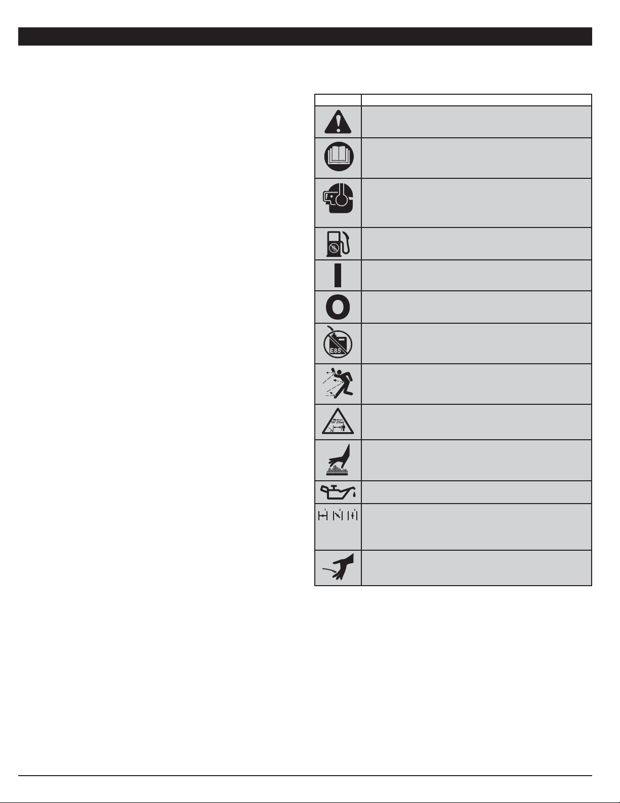
SYMBOL MEANING
• SAFETY ALERT SYMBOL
Indicates danger, warning or caution. May be used in
conjunction with other symbols or pictographs.
• READ OPERATOR'S MANUAL
WARNING: Read the operator’s manual(s) and follow all
warnings and safety instructions. Failure to do so can result in
serious injury to the operator and/or bystanders.
• WEAR EYE AND HEARING PROTECTION
WARNING: Thrown objects and loud noise can cause
severe eye injury and hearing loss. Wear eye protection
meeting ANSI Z87.1-1989 standards and ear protection
when operating this unit. Use a full face shield when needed.
• UNLEADED FUEL
Always use clean, fresh unleaded fuel
• ON/OFF STOP CONTROL
ON / START / RUN
• ON/OFF STOP CONTROL
OFF or STOP
• DO NOT USE E85 FUEL IN THIS UNIT
WARNING: It has been proven that fuel containing greater
than 10% ethanol will likely damage this engine and void the
warranty.
• THROWN OBJECTS AND ROTATING CUTTER CAN
CAUSE SEVERE INJURY
WARNING: Small objects can be propelled at high speed,
causing injury. Keep away from the rotating rotor.
• KEEP BYSTANDERS AWAY
WARNING: Keep all bystanders, especially children and
pets, at least 50 feet (15 m) from the operating area.
• HOT SURFACE WARNING
Do not touch a hot muffler or cylinder. You may get burned.
These parts get extremely hot from operation. When turned
off they remain hot for a short time.
• OIL
Refer to operator’s manual for the proper type of oil.
• CHOKE CONTROL
1. • FULL choke position
2. • PARTIAL choke position
3. • RUN choke position
• SHARP BLADE
WARNING: Sharp blade on cutting attachment shield. To
prevent serious injury, do not touch the line cutting blade.
Page 4
4
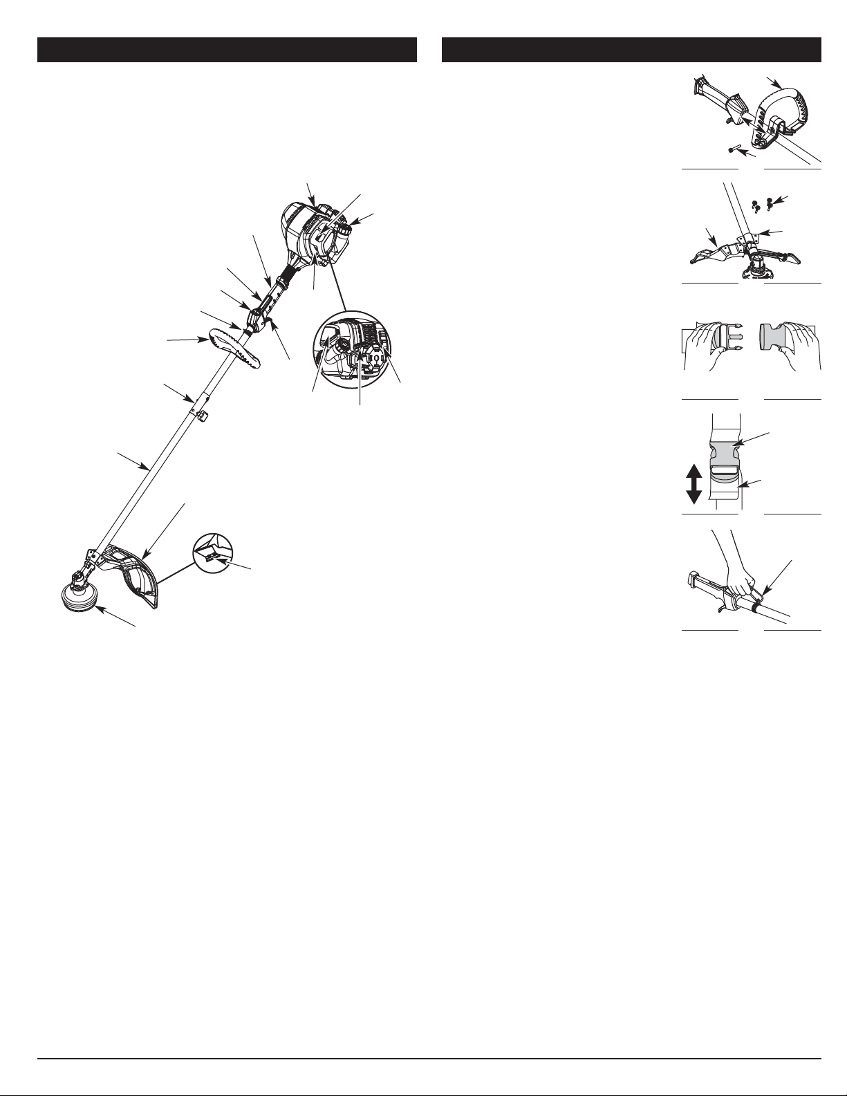
KNOW YOUR UNIT ASSEMBLY INSTRUCTIONS
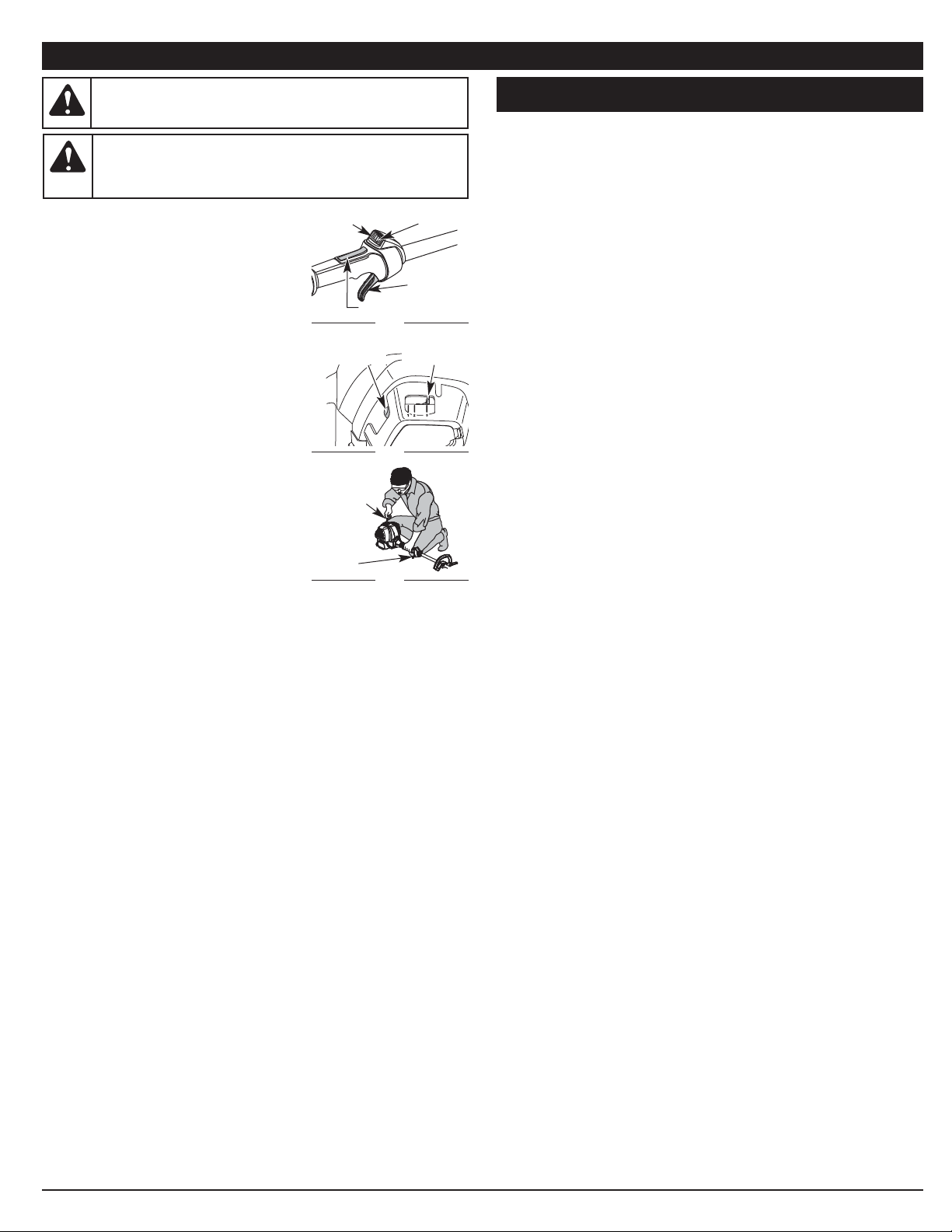
ADJUSTING THE D-HANDLE
1. Loosen the bolt on the handle just enough to
move it (Fig. 1).
2. While holding the unit in the operating
position (Fig. 16), move the D-handle to the
location that provides the best grip.
3. Tighten the bolt until the D-handle is secure.
(Fig. 1)
INSTALL THE CUTTING HEAD SHIELD
1. Place the cutting head shield onto the guard
mount bracket, making sure to align the
holes on the shield with the ones in the
guard mount bracket. (Fig. 2)
2. Take the 4 shield screws and screw each
one into the shield until finger tight.
3. Using a Phillips screwdriver, tighten the
screws until the shield is firmly in place.
INSTALL THE SHOULDER SUPPORT
1. Put the shoulder support on using the clip.
(Fig. 3).
2. Adjust by lifting slightly on the rear of the
lower clip then push or pull the loose end of
the strap length to fit the operator’s size and
comfort. (Fig. 4).
3. Attach the shoulder clip to the unit. (Fig. 5)
Cutting Head Shield
Fuel
Cap
Throttle
Control
D-Handle
Cutting Head
Shaft Grip
Primer
Bulb
Choke Lever
Spark Plug
On/Off Stop Control
Shaft Housing
Starter
Rope
Grip
Line Cutting Blade
Muffler
Air Filter
Cover
APPLICATIONS
As a trimmer:
• Cutting grass and light weeds.
• Edging
• Decorative trimming around trees, fences, etc.
Rapid-Link™
Fig. 2
Guard
Mount
Bracket
Screw (4)
Cutting
Head
Shield
D-Handle
Bolt
Fig. 1
6 in.
(15.24 cm)
Minimum
Throttle Lock-out
Shoulder Strap Clip
TOOLS REQUIRED:
• Phillips screwdriver
• 3/8” socket
Fig. 3
Fig. 4
Adjustment
Ta b
Support
Clip
Fig. 5
Support
Fitting
Page 5
FUELING THE UNIT
1. Remove the fuel cap (Fig. 9).
2. Place the gas container’s spout into the fill
hole on the fuel tank (Fig. 9) and fill the tank.
NOTE: Do not overfill the tank.
3. Wipe up any gasoline that may have spilled.
4. Reinstall the fuel cap.
5. Move the unit at least 30 ft. (9.1 m) from the
fueling source and site before starting the
engine.
NOTE: Dispose of the old gasoline in accordance with federal, state and
local regulations.
5
OIL AND FUEL INFORMATION
RECOMMENDED OIL TYPE
Using the proper type and weight of oil in the crankcase is extremely
important. Check the oil before each use and change the oil regularly. Failure
to use the correct oil, or using dirty oil, can cause premature engine wear
and failure.
Use a high-quality SAE 30 weight oil of API (American Petroleum Institute)
service class SF, SG, SH.
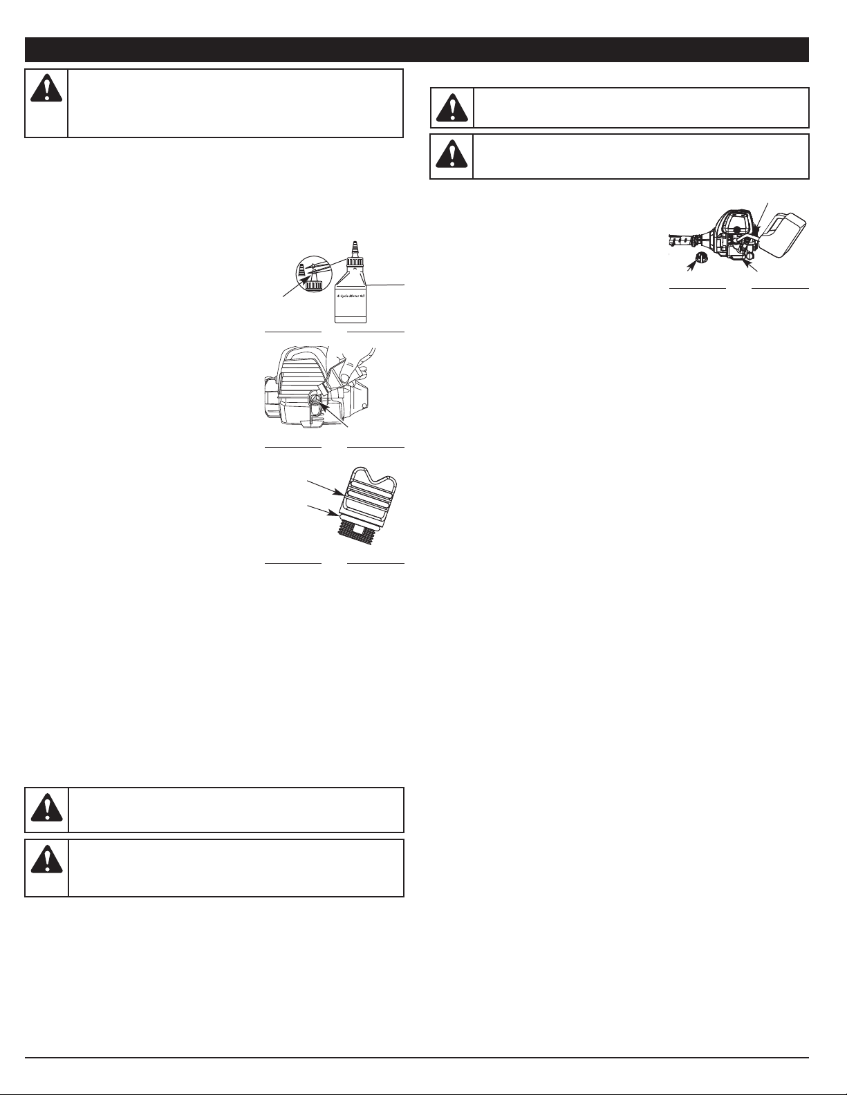
ADDING OIL TO CRANKCASE: INITIAL USE
NOTE: This unit is shipped without oil. In
order to avoid damage to the unit, put
oil in the crankcase before you
attempt to start the unit.
Your unit is supplied with one 2.2 fl.oz. (60 ml)
bottle of SAE 30 SF, SG, SH oil (Fig. 6).
NOTE: Save the bottle of oil. It can be used to
measure the correct amount during
future oil changes. See Changing the Oil.
1. Unscrew the top of the bottle of oil and
remove the paper seal covering the opening.
Replace the top. Next, cut the tip off the
funnel spout (Fig. 6).
2. Place unit on a flat, level surface.
3. Remove the oil fill plug from the crankcase
(Fig. 8).
4. Pour the entire bottle of oil into the oil fill
hole (Fig. 7).
NOTE: Never add oil to the fuel or fuel tank.
5. Wipe up any oil that may have spilled and
reinstall the oil fill plug.
Check oil before each use and change as
needed. Refer to Checking the Oil Level.
RECOMMENDED FUEL TYPE
Old fuel is the primary reason for improper unit
performance. Be sure to use fresh, clean, unleaded gasoline.
NOTE: This is a four cycle engine. In order to avoid damage to the unit, do
not mix oil with gasoline.
Definition of Blended Fuels
Today's fuels are often a blend of gasoline and oxygenates such as ethanol,
methanol or MTBE (ether). Alcohol-blended fuel absorbs water. As little as 1%
water in the fuel can make fuel and oil separate or form acids when stored.
Use fresh fuel (less than 30 days old), when using alcohol-blended fuel.
Using Blended Fuels
If you choose to use a blended fuel, or its use is unavoidable, follow
recommended precautions:
• Always use fresh unleaded gasoline
• Use the fuel additive STA-BIL® or an equivalent
• Drain tank and run the engine dry before storing unit
Using Fuel Additives
The use of fuel additives, such as STA-BIL® Gas Stabilizer or an equivalent,
will inhibit corrosion and minimize the formation of gum deposits. Using a
fuel additive can keep fuel from forming harmful deposits in the carburetor
for up to six (6) months. Add 0.8 oz. (23 ml) of fuel additive per gallon of fuel
according to the instructions on the container. NEVER add fuel additives
directly to the unit's gas tank.
WARNING: OVERFILLING OIL CRANKCASE MAY CAUSE
SERIOUS PERSONAL INJURY. Check and maintain the proper oil
level in the crank case; it is important and cannot be
overemphasized. Check the oil before each use and change it as
needed. See Changing the Oil.
WARNING: Add fuel in a clean, well ventilated outdoor area. Wipe
up any spilled fuel immediately. Avoid creating a source of ignition for
spilt fuel. Do not start the engine until fuel vapors dissipate.
WARNING: Gasoline is extremely flammable. Ignited vapors
may explode. Always stop the engine and allow it to cool before
filling the fuel tank. Do not smoke while filling the tank. Keep
sparks and open flames at a distance from the area.
WARNING: Remove fuel cap slowly to avoid injury from fuel
spray. Never operate the unit without the fuel cap securely in place.
Funnel
Spout
Fig. 6
Oil Fill
Plug
Fig. 8
O-Ring
Fill
Level
Gas Can Spout
Fig. 9
Fuel Cap
Fuel Tank
Fig. 7
Oil Fill Hole
WARNING: DO NOT USE E85 FUEL IN THIS UNIT. It has
been proven that fuel containing greater than 10% ethanol will
likely damage this engine and void the warranty.
Page 6

6
STARTING/STOPPING INSTRUCTIONS
STARTING INSTRUCTIONS
1. Check the oil level in the crankcase. Refer to Checking the Oil Level.
2. Fill the fuel tank with fresh, clean unleaded
gasoline. Refer to Fueling the Unit.
NOTE: There is no need to turn the unit on.
The On/Off Control is in the ON ( I )
position at all times (Fig. 10).
3. Fully press and release the primer bulb 10
times, slowly. Some amount of fuel should
be visible in the primer bulb (Fig. 11). If fuel
cannot be seen in the bulb, press and
release the bulb until fuel is visible.
4. Place the choke lever in Position 1 (Fig. 11).
5. Crouch in the starting position (Fig. 12). Press
the throttle lockout in and squeeze the throttle
control lever. Pull the starter rope 5 times.
6. Place the choke lever in Position 2 (Fig. 11).
7. While pressing the throttle lockout in and
squeezing the throttle control , pull the
starter rope 3 to 5 times to start the engine.
8. Keep the throttle squeezed and allow the
engine to warm up for 30 to 60 seconds.
9. While continuing to squeeze the throttle
control, place the choke lever in Position 3
(Fig. 11) and warm for an additional 60
seconds. The unit may be used during this
time.
NOTE: Unit is properly warmed up when
engine accelerates without hesitation.
IF... the engine hesitates, return the choke lever to Position 2 (Fig. 11)
and continue warm-up.
IF... the engine does not start, go back to step 3.
IF... the engine fails to start after a few attempts, place the choke lever
in Position 3 and squeeze the throttle control. Pull starter rope until
unit starts.
IF WARM... If the engine is already warm, go back to step 6.
STOPPING INSTRUCTIONS
1. Release the throttle control and allow the engine to cool down by idling.
2. Press and hold the On/Off Control switch in the OFF (O) position until the
unit comes to a complete stop (Fig. 10).
WARNING: Operate this unit only in a well-ventilated outdoor area.
Carbon monoxide exhaust fumes can be lethal in a confined area.
WARNING: Avoid accidental starting. Make sure you are in the
starting position when pulling the starter rope (Fig. 12). To avoid
serious injury, the operator and unit must be in a stable position
while starting.
Throttle
Control
Fig. 10
Starter
Rope
Fig. 12
Throttle
Control
Start / On (I)
Stop / Off (O)
Throttle Lockout
Fig. 11
Primer Bulb
Choke Lever
HOW TO START THE UNIT USING THE ELECTRIC STARTER OR POWER
START BIT ACCESSORY.
NOTE- This Unit Can Use an Electric Start or Power Start Bit™
Optional Accessory!
Please refer to the Electric Starter or Power Start Bit operator’s
manual for proper use of this feature. (Items Sold Separately!
Please refer to page 10 of this manual about purchasing these
accessories.)
STARTING INSTRUCTIONS
1. Check the oil level in the crankcase. Refer to Checking the Oil Level.
2. Fill the fuel tank with fresh, clean unleaded gasoline. Refer to Fueling the
Unit.
NOTE: There is no need to turn the unit on. The On/Off Control is in the
ON ( I ) position at all times (Fig. 10).
3. Fully press and release the primer bulb 10 times, slowly. Some amount of
fuel should be visible in the primer bulb (Fig. 11). If fuel cannot be seen in
the bulb, press and release the bulb until fuel is visible.
4. Move the choke lever to Position 1 (Fig. 11).
5. Crouch in the starting position (Fig. 12). Place the electric starter or power
start bit into the back of the unit. Refer to the Operation section of the
Electric Starter or Power Start Bit operator’s manual.
6. Press the throttle lockout in and squeeze the throttle control lever. Press
and hold the electric starter or drill ON (I) button for 2 seconds.
7. Move the choke lever to Position 2 (Fig. 11).
8. Squeeze the throttle control lever, press and hold the electric starter or
drill ON (I) button for 2-second intervals until the unit starts.
9. Continue to squeeze the throttle control, remove the electric starter or drill
from the unit and allow the engine to warm up for 30 to 60 seconds.
10. Continue squeezing the throttle control, move the choke lever to
Position 3 (Fig. 11) and run the unit for an additional 60 seconds. The unit
may be used during this time.
NOTE: Unit is properly warmed up when engine accelerates without
hesitation.
IF... the engine hesitates, return the choke lever to Position 2 (Fig. 11)
and continue warm-up.
IF... the engine does not start, go back to step 3.
IF... the engine fails to start after a few attempts, place the choke lever
in Position 3 and squeeze the throttle control. Press and hold the
electric starter or drill ON (I) button for 2-second intervals until the
unit starts.
IF WARM... If the engine is already warm, go back to step 7.
STOPPING INSTRUCTIONS
1. Release the throttle control and allow the engine to cool down by idling.
2. Press and hold the On/Off Control switch in the OFF (O) position until the
unit comes to a complete stop (Fig. 10).
IF USING THE OPTIONAL ELECTRIC STARTER OR POWER START
BIT™ ACCESSORY
Page 7
7
ADJUSTING TRIMMING LINE LENGTH
The cutting head allows you to release trimming line without stopping the
engine. To release more line, lightly tap the cutting attachment on the ground
(Fig. 17) while operating the trimmer at high speed.
NOTE: Always keep the trimming line fully
extended. Line release becomes more
difficult as the cutting line becomes
shorter.
Each time the head is bumped, about 1 inch
(25.4 mm) of trimming line is released. A blade
in the cutting attachment shield will cut the line
to the proper length if excess line is released.
For best results, tap the cutting head on bare
ground or hard soil. If line release is attempted in tall grass, the engine may
stall. Always keep the trimming line fully extended. Line release becomes
more difficult as the cutting line becomes shorter.
NOTE: Do not rest the cutting head on the ground while the unit is running.
Some line breakage will occur from:
• Entanglement with foreign matter
• Normal line fatigue
• Attempting to cut thick, stalky weeds
• Forcing the line into objects such as walls or fence posts
TIPS FOR BEST TRIMMING RESULTS
• For best trimming results, operate unit at full throttle.
• Keep the cutting attachment parallel to the ground.
• Do not force the cutting attachment. Allow the tip of the line to do the
cutting, especially along walls. Cutting with more than the tip will reduce
cutting efficiency and may overload the engine.
• Cut grass over 8 inches (200 mm) by working from top to bottom in small
increments to avoid premature line wear or engine drag.
• Slowly move the trimmer into and out of the cutting area at the desired
height. Move either in a forward-backward or side-to-side motion. Cutting
shorter lengths produces the best results.
• Trim only when grass and weeds are dry.
• The life of your cutting line is dependent upon:
• Proper adherence of explained trimming techniques
• What vegetation is cut
• Where vegetation is cut
For example, the line will wear faster when trimming against a foundation
wall as opposed to trimming around a tree.
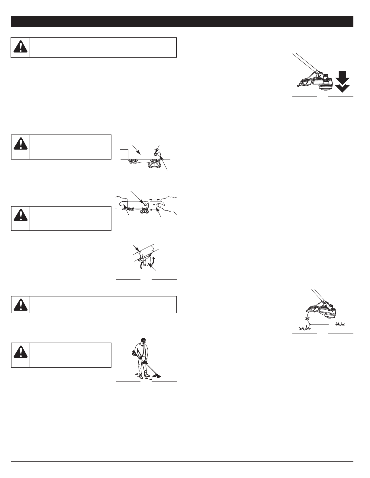
DECORATIVE TRIMMING
Decorative trimming is accomplished by removing all vegetation around
trees, posts, fences and more.
Rotate the whole unit so that the cutting attachment is at a 30° angle to the
ground (Fig. 18).
OPERATING INSTRUCTIONS
OPERATING THE RAPID-LINK™ SYSTEM
The Rapid-Link™ system enables the use of these optional Add-Ons:
Trimmer . . . . . . . . . . . . . . . . . . . . . . . . . . . . . . . . . . . . . . . . . . . . . . . . . AF720
Hedge Trimmer . . . . . . . . . . . . . . . . . . . . . . . . . . . . . . . . . . . . . . . . . . AH720
Brushcutter . . . . . . . . . . . . . . . . . . . . . . . . . . . . . . . . . . . . . . . . . . . . . BC720*
Cultivator . . . . . . . . . . . . . . . . . . . . . . . . . . . . . . . . . . . . . . . . . . . . . . GC720
Edger. . . . . . . . . . . . . . . . . . . . . . . . . . . . . . . . . . . . . . . . . . . . . . . . . . . LE720
Pole Saw . . . . . . . . . . . . . . . . . . . . . . . . . . . . . . . . . . . . . . . . . . . . . . . PS720
Straight Shaft Trimmer. . . . . . . . . . . . . . . . . . . . . . . . . . . . . . . . . . . . . SS725
Turbo Blower . . . . . . . . . . . . . . . . . . . . . . . . . . . . . . . . . . . . . . . . . . . . TB720
*Do NOT use this attachment with an electric powered unit.
Removing the Cutting Attachment or Add-On
1. Turn the knob counterclockwise to loosen
(Fig. 15).
2. Press and hold the release button (Fig. 13).
3. While firmly holding the upper shaft housing,
pull the cutting attachment or add-on straight
out of the Rapid-Link™ coupler (Fig. 14).
Installing the Cutting Attachment or Add-On
NOTE: Place the unit on the ground or on a
work bench to make add-on
installation or removal easier.
1. Turn knob counterclockwise to loosen (Fig. 15).
2. While firmly holding the add-on, push it straight
into the Rapid-Link™ coupler (Fig. 14).
NOTE: Aligning the release button with the
guide recess will help installation
(Fig. 13).
3. Turn the knob clockwise to tighten (Fig. 15).
For edging (when using the line head cutting attachment with Rapid-Link™
models), lock the release button of the cutting attachment into the 90°
edging hole (Fig. 15).
HOLDING THE TRIMMER
Before operating the unit, stand in the operating
position (Fig. 16). Check for the following:
• The operator is wearing eye protection and
proper clothing
• With a slightly-bent right arm, the operator’s right hand is holding the
shaft grip
• The operator’s left arm is straight, the left hand holding the handle
• The unit is at waist level
• The cutting attachment is parallel to the ground and easily contacts the
grass without the need to bend over
WARNING: Before you begin using any attachment, read and
understand the manual that came with the attachment. Follow all
safety information contained within.
WARNING: To avoid serious
personal injury and damage to the
unit, shut the unit off before
removing or installing add-ons.
CAUTION: Lock the release button in the primary hole and
securely tighten the knob before operating this unit.
CAUTION: Add-ons are to be
used in the primary hole only. Using
the wrong hole could lead to
personal injury or damage to the unit.
Guide Recess
Fig. 13
Release
Button
Rapid-Link™
Coupler
Upper Shaft
Housing
Fig. 14
Lower Shaft
Housing
Primary Hole
Knob
Fig. 15
90˚ Edging Hole
(Trimmer Only)
WARNING: Always wear eye,
hearing, foot and body protection to
reduce the risk of injury when
operating this unit.
Fig. 16
Fig. 17
Fig. 18
Page 8
8
MAINTENANCE AND REPAIR INSTRUCTIONS
4. Remove the oil fill plug.
5. Check the oil level. Oil should be just to the
bottom of the threads of the oil fill hole.
(Fig. 24).
6. If the level is low, add a small amount of oil
to the oil fill hole and recheck (Fig. 24).
Repeat this procedure until the oil level
reaches the bottom of the threads in the oil
fill hole.
NOTE: Do not overfill the unit.
NOTE: Make sure the O-ring is in place on the
oil fill plug when checking and
changing the oil (Fig. 23).
CHANGING THE OIL
Change the oil while the engine is still warm. The
oil will flow freely and carry away more impurities.
1. Remove the oil fill plug.
2. Pour the oil out of the oil fill hole and into a
container by tipping the unit to the side (Fig.
25). Allow ample time for complete drainage.
3. Wipe up any oil residue on the unit and clean
up any oil that may have spilled. Dispose of
the oil according to federal, state and local
regulations.
4. Refill the crankcase with 2.2 fl.oz. (60 ml) of SAE 30 SF, SG, SH oil.
NOTE: Use the bottle and spout saved from initial use to measure the
correct amount of oil. The top of the label on the bottle measures
approximately 3.4 ounces (100 ml) (Fig. 26). Check the level (Fig.
24). If the level is low, add a small amount of oil and recheck. Do
not overfill (Fig. 24).
5. Replace the oil fill plug.
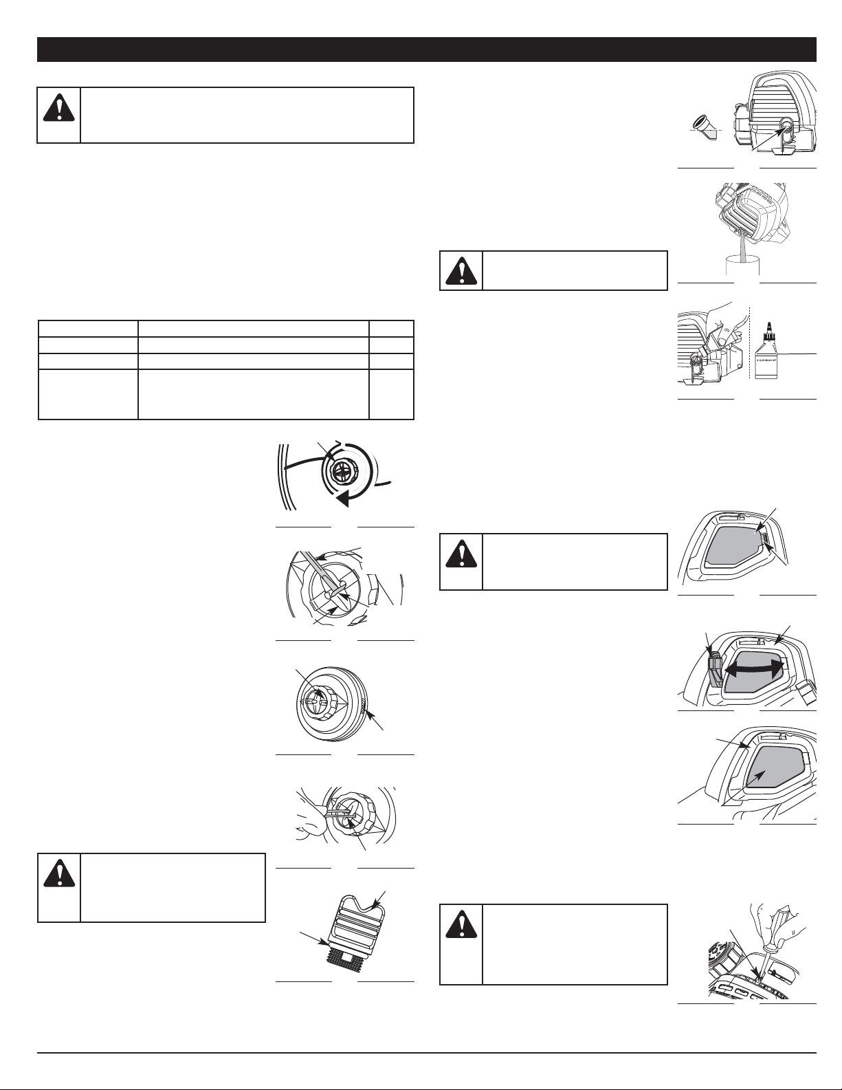
AIR FILTER MAINTENANCE
Cleaning the Air Filter
Failure to maintain the air filter properly can
result in poor performance or can cause
permanent damage to the engine.
1. Open the air filter cover by pressing the lock
tab in and pulling out on the air filter cover
(Fig. 27 & 25).
2. Remove the air filter (Fig. 29).
3. Wash the filter in detergent and water. Rinse
the filter thoroughly and allow it to dry.
4. Apply enough clean SAE 30 motor oil to
lightly coat the filter.
5. Squeeze the filter to spread and remove
excess oil.
6. Replace the air filter into the base plate
(Fig. 29).
NOTE: If the unit is operated without the air
filter, you will VOID the warranty.
7. Reinstall the air filter cover. Position the two small tabs on the air filter
cover into the two slots in the back plate and press the air filter cover
down, making sure to align the lock tab with the lock tab slot, until it
snaps into place (Fig. 28 & 27).
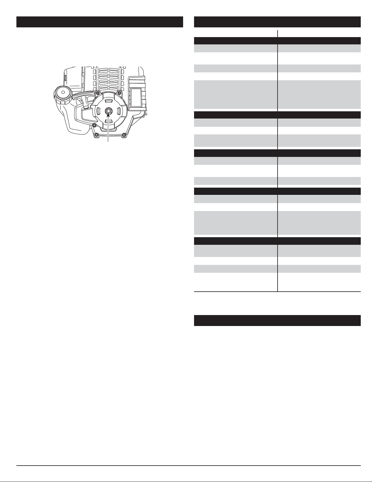
IDLE SPEED ADJUSTMENT
The idle speed of the engine is adjustable. An
idle adjustment screw is between the air filter
cover and the engine starter housing (Fig. 30).
CAUTION: Wear gloves to prevent
injury when handling the unit.
WARNING: To avoid serious
personal injury, always turn the unit
off and allow it to cool before you
clean or service it.
Oil Fill Hole
Fig. 24
Fig. 25
Fill
Level
Fig. 26
Add 1.4-1.5
Oz.
(41-44 ml)
Air Filter
Cover Tab
Fig. 27
Air Filter Cover
Air Filter
Fig. 29
Air Filter
Cover
Fig. 28
Back Plate
Idle
Adjustment
Screw
Fig. 30
Back
Plate
MAINTENANCE SCHEDULE
Perform these required maintenance procedures at the frequency stated in
the table. These procedures should also be a part of any seasonal tune-up.
NOTE: Some maintenance procedures may require special tools or skills.
If you are unsure about these procedures take your unit to any
non-road engine repair establishment, individual or authorized
service dealer.
NOTE: Maintenance, replacement, or repair of the emission control
devices and system may be performed by any non-road engine
repair establishment, individual or authorized service dealer.
NOTE: Please read the California/EPA statement that came with the unit
for a complete listing of terms and coverage for the emissions
control devices, such as the spark arrestor, muffler, carburetor, etc.
WARNING: To prevent serious injury, never perform
maintenance or repairs with unit running. Always service and
repair a cool unit. Disconnect the spark plug wire to ensure that
the unit cannot start.
REMOVING THE LINE
1. Rotate the bump knob clockwise until all line
is inside the cutting head (Fig. 19).
2. Using a flat-head screwdriver, insert the tip
into the line dimple and just under the
exposed portion of the line (Fig. 20)
3. Pull the line straight out until all line is
removed from the cutting head.
LINE INSTALLATION
Always use original equipment manufacturer
0.095 in. (2.41 mm) replacement line.
1. Align the arrows on the bump knob with the
spool cover eyelets, if they are not already
(Fig. 21).
2. Using 10 ft. (3 m) of 0.095 in. (2.41 mm)
replacement line push both ends of the line
through the holes in the bump knob until they
protrude through the eyelets on both sides of
the cutting head. Continue pulling the line
until approximately 5 ft. (1.5 m) is visible from
both sides of the cutting head. (Fig. 22)
3. Hold the spool cover, turn the bump knob
clockwise to wind the line around the spool
until about 5 in. (12.7 cm) is protruding from
each side of the cutting head. (Fig. 19)
4. Start the unit and bump the cutting head on
the ground until the desired cutting length is
achieved. Excess line will be trimmed off by
the line blade.
NOTE: If the cutting line ends are pulled into
the cutting head or the line becomes
twisted, refer to Removing the Line.
CHECKING THE OIL LEVEL
The importance of checking and maintaining the
proper oil level in the crankcase cannot be
overemphasized. Check oil before each use:
1. Stop the engine and allow oil to drain into
the crankcase.
2. Place the unit on a flat, level surface to get a proper oil level reading.
3. Keep dirt, grass clippings and other debris out of the engine. Clean the
area around the oil fill plug before removing it.
Flat-Head
Screw
Driver
Arrows
Trimmer
Line
Dimple
Eyelet
Trimmer line
Bump Knob
FREQUENCY MAINTENANCE REQUIRED SEE
Every 10 hours Clean and oil air filter p. 8
After first 10 hours Change oil p. 8
Every 40 hours
Change oil
Check rocker arm to valve clearance and adjust
Check spark plug condition and gap
p. 8
p. 9
p. 9
Fig. 22
Fig. 21
Fig. 20
Fig. 19
WARNING: To prevent extensive
engine wear and damage to the
unit, always maintain the proper oil
level in the crankcase. Never
operate the unit with a low oil level.
Fig. 23
O-Ring
Oil Fill Plug
WARNING: The cutting
attachment may spin during idle
speed adjustments. Wear protective
clothing and observe all safety
instructions to prevent serious
personal injury.
Page 9
9
9. Reinstall the rocker arm cover using a new gasket. Torque the screw to
20–30 in•lb (2.2–3.4 N•m).
10. Check the spark plug and reinstall. See Replacing the Spark Plug.
11. Replace the spark plug wire.
12. Reinstall the engine cover. Check alignment of the cover before
tightening the screws. Tighten screws.
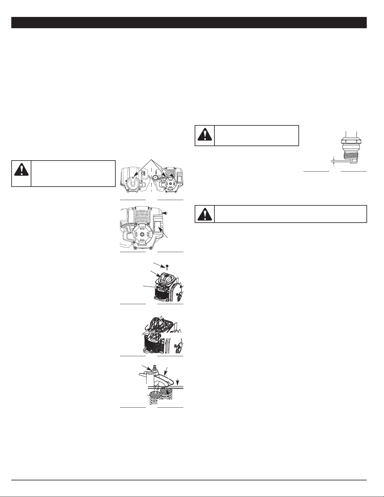
REPLACING THE SPARK PLUG
Use a replacement part number 753-05784 or Champion® RDZ4H spark
plug. The correct air gap is 0.025 in. (0.635 mm).
1. Stop the engine and allow it to cool. Remove the two (2) screws on back
of the engine cover and the one on the front of the engine cover with a
Flat-head or T-25 Torx screwdriver (Fig. 31).
2. Grasp the plug wire firmly and pull the cap from the spark plug.
3. Clean dirt from around the spark plug. Remove the spark plug from the
cylinder head by turning a 5/8 in. socket counterclockwise.
3. Replace cracked, fouled or dirty spark plug.
Set the air gap at 0.025 in. (0.635 mm) using
a feeler gauge (Fig. 36).
4. Install a correctly-gapped spark plug in the
cylinder head. Turn the 5/8 in. socket
clockwise until snug.
If using a torque wrench torque to: 110-120 in.•lb. (12.3-13.5 N•m)
Do not over tighten.
CLEANING
Use a small brush to clean off the outside of the unit. Do not use strong
detergents. Household cleaners that contain aromatic oils such as pine and
lemon, and solvents such as kerosene, can damage plastic housing or
handle. Wipe off any moisture with a soft cloth.
STORAGE
• Never store the unit with fuel in the tank where fumes may reach an
open flame or spark.
• Allow the engine to cool before storing.
• Lock up the unit to prevent unauthorized use or damage.
• Store the unit in a dry, well-ventilated area.
• Store the unit out of the reach of children.
Short Term Storage (1-2 weeks)
1. Store the unit in a horizontal position. If this is not possible, store the unit
vertically with the engine at the top.
Long Term Storage
1. Drain all gasoline from the gas tank into a container. Do not use gas that
has been stored for more than 30 days. Dispose of the old gasoline in
accordance with federal, state and local regulations.
2. Start the engine and allow it to run until it stalls. This ensures that all
gasoline has been drained from the carburetor.
3. Allow the engine to cool. Remove the spark plug and put 5 drops of high
quality motor oil into the cylinder. Pull the starter rope slowly to distribute
the oil. Reinstall the spark plug.
NOTE: Remove the spark plug and drain all of the oil from the cylinder
before attempting to start the trimmer after storage.
4. Change the oil, referring to Changing the Oil. Dispose of the old oil in
accordance with federal, state and local regulations.
5. Thoroughly clean the unit and inspect for any loose or damaged parts.
Repair or replace damaged parts and tighten loose screws, nuts or bolts.
The unit is ready for storage.
NOTE: Careless adjustments can seriously damage your unit. An
authorized service dealer should make carburetor adjustments.
If, after checking the fuel and cleaning the air filter, the engine still will not
idle, adjust the idle speed screw as follows:
1. Start the engine and let it run at a high idle for a minute to warm up. Refer
to Starting/Stopping Instructions.
2. Release the throttle trigger and let the engine idle. If the engine stops,
insert a small phillips or flat blade screwdriver into the hole in the air
filter/muffler cover (Fig. 30). Turn the idle speed screw in, clockwise, 1/8
of a turn at a time (as needed) until the engine idles smoothly.
NOTE: The cutting attachment should not rotate when the engine idles.
3. If the cutting attachment rotates when the engine idles, turn the idle
speed screw counterclockwise 1/8 of a turn at a time (as needed), to
reduce idle speed.
Checking the fuel, cleaning the air filter, and adjusting the idle speed should
solve most engine problems. If not and all of the following are true:
• the engine will not idle
• the engine hesitates or stalls on acceleration
• there is a loss of engine power
Have the carburetor adjusted by an authorized service dealer.
ROCKER ARM CLEARANCE
This requires disassembly of the engine. If
feeling unsure or unqualified to perform this,
take the unit to an authorized service center.
• The engine must be cold when checking or
adjusting the valve clearance.
• This task should be performed inside in a
clean, dust free area.
1. Remove the two (2) screws on back of the
engine cover and the one on the front of the
engine cover with a Flat-head or T-25 Torx
screwdriver (Fig. 31).
2. Remove the engine cover (Fig. 32).
3. Disconnect the spark plug wire.
4. Clean dirt from around the spark plug.
Remove the spark plug from the cylinder
head by turning a 5/8 in. socket
counterclockwise.
5. Clean dirt from around the rocker arm cover.
Remove the screw holding the rocker arm
cover with a large flat blade screwdriver or
Torx T-25 bit (Fig. 33). Remove the rocker
arm cover and gasket.
6. Pull the starter rope slowly to bring the
piston to the top of its travel, (known as top
dead center). Check that:
• The piston is at the top of its travel while
looking in the spark plug hole (Fig. 33)
• Both rocker arms move freely, and both
valves are closed
If these statements are not true, repeat this
step.
7. Slide the feeler gauge between the rocker
arm and the valve return spring. Measure the
clearance between the valve stem and
rocker arm (Fig. 35). Measure both the intake
and exhaust valves.
The recommended clearance for both intake
and exhaust is .003 – .006 in. (.076 – 0.152
mm). Use a standard automotive .005 in. (0.127 mm) feeler gauge. The
feeler gauge should slide between the r
ocker arm and valve stem with a
slight amount of resistance, without binding. Figure 34 and 35 show how to
measure the clearance.
8. If the clearance is not within specification:
a. Turn the adjusting nut using a 5/16 inch (8 mm) wrench or nut driver
(Fig. 35).
• To increase clearance, turn the adjusting nut counterclockwise.
• To decrease clearance, turn the adjusting nut clockwise.
b. Recheck both clearances, and adjust as necessary.
Fig. 36
0.025 in.
(0.635 mm)
MAINTENANCE AND REPAIR INSTRUCTIONS
WARNING: To avoid serious personal injury, always turn the
unit off and allow it to cool before cleaning or servicing it.
WARNING: To avoid serious
personal injury, always turn the unit
off and allow it to cool before
cleaning or servicing it.
WARNING: Do not sand blast,
scrape or clean electrodes. Grit in the
engine could damage the cylinder.
Rocker Arm
Cover
Fig. 33
Screw
Adjusting Nuts
Fig. 34
INTAKE
Valve Stem
Fig. 35
Exhaust
Adjusting
Nut
Feeler
Gauge
Rocker Arm
Rocker
Arms
EXHAUST
Spark
Plug Hole
0.003–0.006
in.
(0.076–0.152
mm)
Fig. 31
Fig. 32
Muffler
Remove Screws
Engine
Cover
Page 10
CAUSE ACTION
Cutting attachment bound with
grass
Stop the engine and clean cutting
attachment
Cutting attachment out of line Refill with new line
Line twisted when refilled Remove and rewind the line
Not enough line is exposed
Push the bump knob and pull out
line until 4 inches (102 mm) of line
is outside of the cutting attachment
Old fuel (over 30 days) Drain fuel tank and add fresh fuel
Fouled spark plug Replace or clean the spark plug
The outside temperature is above
90˚ F
Move the choke lever to Position 2,
squeeze the throttle control and pull
the starter rope until the unit starts.
Operate the unit in Position 2.
Old fuel (over 30 days) Drain fuel tank and add fresh fuel
Cutting attachment bound with
grass
Stop the engine and clean the
cutting attachment
Dirty air filter Clean or replace the air filter
Empty fuel tank Fill fuel tank with fuel
Primer bulb wasn't pressed enough
Press primer bulb fully and slowly
10 times
Old fuel (over 30 days) Drain fuel tank and add fresh fuel
Fouled spark plug Replace or clean the spark plug
Engine is over heated
Move the choke lever to Position 2,
squeeze the throttle control and pull
the starter rope until the unit starts.
Run the unit for 2-5 minutes. Then
move the choke lever to Position 3.
Air filter is plugged Replace or clean the air filter
Old fuel (over 30 days) Drain fuel tank and add fresh fuel
Improper idle speed
Adjust according to the Idle Speed
Adjustment section
ENGINE WILL NOT START
ENGINE WILL NOT ACCELERATE
ENGINE WILL NOT IDLE
If further assistance is required, contact your authorized service dealer.
TROUBLESHOOTING
ENGINE LACKS POWER OR STALLS WHEN CUTTING
* All specifications are based on the latest product information available at
the time of printing. We reserve the right to make changes at any time
without notice.
Engine Type . . . . . . . . . . . . . . . . . . . . . . . . . . . . . . . . . . Air-Cooled, 4-Cycle
Displacement . . . . . . . . . . . . . . . . . . . . . . . . . . . . . . . . . . . 1.5 cu. in. (25 cc)
Operating RPM . . . . . . . . . . . . . . . . . . . . . . . . . . . . . . . . . 6,800 - 9,300 rpm
Idle Speed RPM . . . . . . . . . . . . . . . . . . . . . . . . . . . . . . . . 2,800 - 3,600 rpm
Valve clearance . . . . . . . . . . . . . . . . . . . . 0.003–0.006 in. (0.076–0.152 mm)
Spark Plug Gap . . . . . . . . . . . . . . . . . . . . . . . . . . . . . 0.025 inch (0.635 mm)
Lubrication . . . . . . . . . . . . . . . . . . . . . . . . . . . . . . . . . . . . . . . . . . SAE 30 Oil
Crankcase Oil Capacity . . . . . . . . . . . . . . . . . . . . . . . . . . . . . . 2.2 oz (60 ml)
Fuel . . . . . . . . . . . . . . . . . . . . . . . . . . . . . . . . . . . . . . . . . . . . . . . . . Unleaded
Fuel Tank Capacity . . . . . . . . . . . . . . . . . . . . . . . . . . . . . . . . . 12 oz (355 ml)
Approximate Unit Weight (without fuel). . . . . . . . . . . . . . . . . 14.5 lbs (5.4 kg)
Cutting Mechanism . . . . . . . . . . . . . . . . . . . . . . . . Professional Bump Head
Line Spool Diameter: . . . . . . . . . . . . . . . . . . . . . . . . . 3.25 inches (82.6 mm)
Trimming Line Diameter:. . . . . . . . . . . . . . . . . . . . . . 0.095 inches (2.41 mm)
Cutting Path Diameter . . . . . . . . . . . . . . . . . . . . . . . . . . . . . 18 in. (45.7 cm.)
SPECIFICATIONS*
CUTTING ATTACHMENT WILL NOT ADVANCE LINE
10
ELECTRIC STARTER AND POWER START BIT™ FEATURES
This unit is designed to be started with an optional electric starter or Power
Start Bit™ that are sold separately. If choosing to start the unit using one of
these features or have questions please contact your local retailer or call
1-877-282-8684 U.S, (1-800-668-1238 Canada), for more information and
purchasing. You may also go to www.cubcadet.com or www.cubcadet.ca.
Electric Start Feature
OPTIONAL ACCESSORY
Page 11

TABLE DES MATIÈRES
Service technique . . . . . . . . . . . . . . . . . . . . . . . . . . . . . . . . . . . . . . . . . . . .11
Consignes de sécurité . . . . . . . . . . . . . . . . . . . . . . . . . . . . . . . . . . . . . . . .12
Familiarisez-vous avec votre appareil . . . . . . . . . . . . . . . . . . . . . . . . . . . . .14
Instructions de montage . . . . . . . . . . . . . . . . . . . . . . . . . . . . . . . . . . . . . . .14
Informations sur l'huile et le carburant . . . . . . . . . . . . . . . . . . . . . . . . . . . .15
Instructions de démarrage et d'arrêt . . . . . . . . . . . . . . . . . . . . . . . . . . . . .16
Mode d'emploi . . . . . . . . . . . . . . . . . . . . . . . . . . . . . . . . . . . . . . . . . . . . . .17
Entretien et réparations . . . . . . . . . . . . . . . . . . . . . . . . . . . . . . . . . . . . . . . .18
Nettoyage et entreposage . . . . . . . . . . . . . . . . . . . . . . . . . . . . . . . . . . . . .19
Accessoire en option . . . . . . . . . . . . . . . . . . . . . . . . . . . . . . . . . . . . . . . . .20
Tableau de dépannage . . . . . . . . . . . . . . . . . . . . . . . . . . . . . . . . . . . . . . . .20
Caractéristiques . . . . . . . . . . . . . . . . . . . . . . . . . . . . . . . . . . . . . . . . . . . . .20
Garantie . . . . . . . . . . . . . . . . . . . . . . . . . . . . . . . . . . . . . . . . . . . . . . . . . . .32
Toutes les informations, illustrations et spécifications contenues dans ce
manuel tiennent compte des dernières informations techniques disponibles au
moment de mettre sous presse. Nous nous réservons le droit d'y apporter des
modifications à tout moment, sans préavis.
Copyright©
2011
MTD SOUTHWEST INC., Tous droits réservés.
Manuel de L'utilisateur
Désherbeuse à 4-temps
ST426s
769-07001 P00 03/11
CONSERVEZ CES INSTRUCTIONS
Obtenez la liste des concessionnaires agréés appelez le 1-877-282-8684 aux
États-Unis ou le 1-800-668-1238 au Canada. Pour de plus amples informations
à propos de votre appareil, visitez www.cubcadet.com ou www.cubcadet.ca.
Si vous éprouvez des difficultés à assembler ce produit ou si vous avez des
questions sur les commandes, l'utilisation ou l'entretien de cet appareil,
veuillez contacter le service à la clientèle.
NE RETOURNEZ PAS L'APPAREIL AU DÉTAILLANT CHEZ QUI VOUS
L'AVEZ ACHETÉ. TOUT SERVICE SOUS GARANTIE NÉCESSITE UNE
PREUVE D'ACHAT.
Tout entretien effectué sur cet appareil pendant et après la période de garantie doit
être fait par un concess- ionnaire agréé uniquement.
PARE-ÉTINCELLES
REMARQUE: à l'intention des utilisateurs opérant dans les terres forestières
des États-Unis et dans les états de Californie, du Maine, de l'Orégon et de
Washington. Toutes les terres forestières des États-Unis et de l'état de Californie
(Codes sur les ressources publiques 4442 et 4443), de l'Orégon et de Washington
exigent de par la loi que certains moteurs à combustion interne utilisés dans des
zones couvertes de taillis ou d'herbe soient équipés d'un pare-étincelles en parfait
état de fonctionnement, ou qu'ils soient conçus, équipés et entretenus pour la
prévention des incendies. Renseignez-vous auprès des autorités de votre province
ou de votre municipalité concernant la réglementation en vigueur. Vous pourriez
être passible d'une amende ou être tenu responsable si vous ne respectez pas
cette réglementation. Cet appareil est équipé d'un pare-étincelles en usine. Si
l'écran pare-étincelles, réf.
753-06334
, doit être remplacé, communiquez avec
le service technique.
Page 12

LISEZ CETTE NOTICE INTEGRALEMENT AVANT D’UTILISER:
• Lisez soigneusement cette notice. Familiarisez-vous avec les
commandes et la marche à suivre pour une bonne utilisation de l'appareil.
• N’utilisez pas cet appareil lorsque vous êtes fatigué, malade, ou sous
l’influence de l’alcool, de drogues, ou de médicaments.
• Tout enfant ou adolescent de moins de 15 ans ne doit pas utiliser cet
appareil, à moins que l'adolescent soit sous la supervision d’un adulte.
• Toutes les protections et tous les dispositifs de sécurité doivent être
installés correctement avant utilisation de l’appareil.
• Inspectez l’appareil avant utilisation. Remplacez les pièces
endommagées. Détectez les fuites de carburant éventuelles. Assurezvous que tous les accessoires sont bien en place. Remplacez les pièces
susceptibles d’être fissurées, ébréchées, ou endommagées. N’utilisez
pas cet appareil si des pièces ont du jeu ou sont endommagées.
• Inspectez la zone avec attention avant de démarrer cet appareil. Retirez tous
les débris et objets durs ou tranchants tels que du verre, les câbles, etc.
• Eloignez les enfants, les personnes à proximité et les animaux familiers
de la zone d’utilisation. Au minimum, faites reculer les enfants, les
personnes à proximité et les animaux familiers de 50 pieds (15 m) ; il
existe néanmoins un risque de projectiles pour les personnes à proximité.
Encouragez-les à porter des lunettes de sécurité. Si quelqu’un
s’approche de vous, arrêtez l’appareil immédiatement.
• N’utilisez jamais de câbles, cordons ou pièces renforcées en métal, qui
peuvent céder et devenir des projectiles dangereux.
• Appuyez sur la manette des gaz et vérifiez que le régime du moteur
revienne automatiquement au ralenti. Effectuez tous les réglages et
réparations avant d’utiliser l’appareil.
ALERTES DE SECURITE POUR LES APPAREILS A ESSENCE
• Stockez uniquement le carburant dans des conteneurs prévus
spécifiquement à cet effet et approuvés pour le stockage de telles
substances.
• Coupez toujours le moteur et laissez-le refroidir avant de remplir le
réservoir d’essence. Ne retirez jamais le bouchon du réservoir d’essence
et ne remplissez jamais ce dernier lorsque le moteur est chaud. Dévissez
lentement le bouchon du réservoir d’essence afin de réduire la pression
avant de le remplir. Ne fumez pas.
• Ajoutez le carburant dans un endroit bien aéré et propre, en plein air, à
l’abri des sources d’étincelles ou flammes vives.
• Ne démarrez jamais l’appareil sans avoir bien revissé le bouchon du
réservoir d’essence.
• Évitez tout ce qui pourrait enflammer le carburant renversé. L’essence
s’étant échappée de l’appareil doit être essuyée immédiatement avant de
démarrer l'appareil. Éloignez l’appareil d’au moins 9,1 m (30 pieds) du site
et de la source du carburant avant de démarrer le moteur. Ne fumez pas.
• L'appareil ne doit pas être démarré ou utilisé à l'intérieur d'un espace ou
d’un bâtiment clos. Inhaler les fumées du pot d’échappement peut
provoquer la mort. Cet appareil doit fonctionner uniquement en extérieur,
dans une zone bien aérée.
LORS DU FONCTIONNEMENT DE L'APPAREIL
• Portez des lunettes de sécurité conformes aux normes ANSI Z87.1,
lesquelles doivent être indiquées sur les lunettes mêmes. Portez des
bouchons d’oreille et des casques antibruit lors de l’utilisation de cet
appareil. Portez un masque si l'appareil émet de la poussière.
• Portez un pantalon long et épais, des bottes, des gants et une chemise à
manches longues. Ne portez pas de vêtements amples, de bijoux, de
pantalons courts, de sandales et ne soyez pas pieds nus. Veillez à ce que
vos cheveux restent au-dessus du niveau des épaules.
• L’écran de l’accessoire de coupe doit toujours être utilisé lorsque vous
vous servez de cet appareil comme débroussailleuse. N'utilisez jamais
cet appareil sans une longueur suffisante des deux fils de coupe, ces
derniers devant être ceux recommandés par le fabricant. La longueur des
fils de coupe ne doit jamais aller au-delà de celle de l’écran.
• Cet appareil dispose d’un embrayage. L'accessoire de coupe reste
immobile lorsque le moteur tourne au ralenti. Dans le cas contraire, faites
ajuster cet appareil par un technicien agréé.
• Ajustez la poignée à votre taille afin d’assurer une prise optimale.
• Assurez-vous que l’accessoire de coupe n’est pas en contact avec tout
autre élément avant de démarrer l’appareil.
• Utilisez cet appareil uniquement en plein jour ou si vous disposez d’un
éclairage artificiel suffisant.
• Evitez les démarrages accidentels. Soyez en position de démarrage
lorsque vous tirez sur le cordon du démarreur. L’utilisateur et l’appareil
doivent être sur un sol ferme lors du démarrage. Référez-vous aux
consignes relatives au démarrage/à l’arrêt de l’appareil.
• Utilisez le bon outil. N’utilisez pas un outil pour des fonctions pour
lesquelles il n’a pas été prévu.
• N’étendez pas trop le bras. Restez toujours à distance et en équilibre.
• Tenez toujours l’appareil à deux mains lorsqu'il est en marche. Assurez
une prise ferme sur les deux poignées ou grips.
• Gardez vos mains, votre visage et vos pieds à distance des parties en
mouvement. Ne touchez pas et ne tentez pas d'arrêter l'accessoire de
coupe lorsqu'il est en rotation.
• Ne touchez pas au moteur, à la transmission ou au pot d'échappement.
Ces parties deviennent extrêmement chaudes lors du fonctionnement,
même après l'arrêt de l'appareil.
• L'appareil ne doit pas fonctionner à un régime supérieur à celui adapté
pour la coupe ou la tonte. Ne faites pas tourner le moteur à haut régime
lorsque vous ne coupez rien.
• Arrêtez toujours le moteur lorsque la coupe est interrompue ou lorsque
vous vous rendez à une autre aire de coupe.
• Si vous butez ou bloquez sur un objet, arrêtez le moteur immédiatement
et vérifiez que l'appareil n'a pas été endommagé. Ne redémarrez pas
l'appareil avant de l'avoir réparé. Ne faites pas fonctionner l’appareil si
certaines pièces ont du jeu ou sont endommagées.
• Arrêtez l’appareil, coupez le moteur, et déconnectez la bougie avant de
l’entretenir ou de le réparer.
• IMPORTANTES CONSIGNES DE SÉCURITÉ •
AVERTISSEMENT :
Lorsque vous utilisez la machine, vous devez
suivre les consignes de sécurité. Veuillez lire ces instructions avant
d’opérer la machine pour vous assurer de la sécurité de l’opérateur et de
tout spectateur. Veuillez conserver ces instructions pour un usage ultérieur.
AVERTISSEMENT :
l'essence est extrêmement inflammable
et ses vapeurs peuvent exploser si on y met le feu. Veuillez
prendre les précautions suivantes.
12
Lisez le(s) manuel(s) de l'utilisateur et suivez tous les avertissements et
consignes de sécurité. Vous pourriez à défaut entraîner des blessures
graves pour vous ou d'autres personnes.
SI VOUS AVEZ DES QUESTIONS, APPELEZ LE 1-877-282-8684 AUX
ÉTATS-UNIS, OU LE 1-800-668-1238 AU CANADA
SYMBOLE SIGNIFICATION
AVERTISSEMENT : le non-respect d’un avertissement peut
causer dommages matériels ou blessures graves pour tous.
Respectez les consignes de sécurité afin de réduire les risques
d'incendie, d'électrocution et de blessures.
MISE EN GARDE : le non-respect d’un avertissement peut
causer dommages matériels ou blessures graves pour tous.
Respectez toujours les consignes de sécurité afin de réduire les
risques d'incendie, d'électrocution et de blessures.
Les symboles de sécurité attirent votre attention sur des dangers potentiels. Ces
symboles et leurs détails explicatifs méritent que vous les lisiez et compreniez
bien. Les avertissements de sécurité ne peuvent éviter les dangers de par euxmêmes. Les consignes ou mises en garde qu'ils donnent ne remplacent pas des
mesures préventives appropriées contre les accidents.
ALERTE DE SÉCURITÉ : Indique un danger, un
avertissement ou une mise en garde. Soyez vigilant afin d'éviter
toute blessure grave. Ce symbole peut être combiné à d'autres
symboles ou pictogrammes.
REMARQUE : donne des informations ou des instructions vitales pour le
fonctionnement ou l'entretien de l'équipement.
DANGER : l e non-respect d’un avertissement peut causer
dommages matériels ou blessures graves pour tous. Respectez
les consignes de sécurité afin de réduire les risques d'incendie,
d'électrocution et de blessures.
CONSIGNES DE SÉCURITÉ
PROPOSITION DE LOI 65 DE CALIFORNIE
AVERTISSEMENT : La fumée d’échappement du moteur,
certains constituants et composants finis contiennent ou émettent
des produits chimiques connus de l’État de Californie comme
étant à l’origine de cancers, de malformations congénitales ou
autres anomalies de la reproduction. Lavez-vous les mains après
manipulation.
Page 13

• Pour cet appareil, utilisez uniquement les pièces et accessoires de
rechange du fabricant. Ils sont disponibles auprès d’un fournisseur
officiel. L’utilisation de pièces ou accessoires non agréés pourrait
entraîner de graves blessures pour l'utilisateur, ou endommager l'appareil,
et annuler votre garantie.
• Dégagez l’herbe et les autres substances nichées dans l’appareil. Elles
peuvent se coincer entre l’accessoire de coupe et l’écran.
• Afin de réduire les risques d’incendie, remplacez les réducteurs antiflamme et les pots d’échappement défaillants. Nettoyez l’herbe, les
feuilles, les couches de graisse excessives et les dépôts de carbone du
moteur et du pot d’échappement.
APRES UTILISATION
• Nettoyez les lames de coupe à l’aide d’un produit d’entretien d’intérieur afin
de retirer les dépôts. Graissez la lame à l'huile pour l’empêcher de rouiller.
• Laissez refroidir le moteur avant de le ranger ou de le déplacer. Lorsque
vous déplacez l’appareil, assurez-vous qu’il ne pose aucun danger.
• Entreposez l’appareil dans une zone sèche, verrouillée ou hors de la
portée des enfants.
• Ne mouillez ou ne pulvérisez jamais d’eau ou tout autre liquide, sur
l’appareil. Veillez à ce que les poignées restent sèches, propres et
dépourvues de tout dépôt. Nettoyez l’appareil après chaque utilisation,
voir les consignes portant sur le nettoyage et le stockage.
• Conservez ces consignes. Consultez-les souvent et utilisez-les pour
mettre en garde les autres utilisateurs. Si vous prêtez cet appareil à
quelqu'un, donnez-lui ces consignes.
CONSERVEZ CES CONSIGNES
CONSIGNES DE SÉCURITÉ
• SYMBOLES DE SÉCURITÉ ET INTERNATIONAUX •
Ce manuel de l'utilisateur décrit les symboles et pictogrammes de sécurité et
internationaux pouvant apparaître sur ce produit. Consultez le manuel de l'utilisateur
pour les informations concernant la sécurité, le montage, le fonctionnement,
l'entretien et les réparations.
13
SYMBOLE SIGNIFICATION
• SYMBOLE ALERTE DE SÉCURITÉ
Indique un danger, un avertissement ou une mise en garde. Ce
symbole peut être combiné à d'autres symboles ou pictogrammes.
• LISEZ LE MANUEL DE L'UTILISATEUR
AVERTISSEMENT : Lisez le manuel de l'utilisateur et
suivez tous les avertissements et consignes de sécurité. Vous
pourriez à défaut entraîner des blessures graves pour vous ou
d'autres personnes.
• PORTEZ DES PROTECTIONS (YEUX ET OREILLES)
AVERTISSEMENT :
les objets projetés et les bruits forts
peuvent endommager la vue et l’ouïe. Portez une visière de norme
ANSI Z87.1-1989 et des protège-oreilles pendant l'utilisation.
• CARBURANT SANS PLOMB
Utilisez toujours du carburant sans plomb frais et propre.
• COMMANDE MARCHE/ARRÊT
ALLUMAGE/DÉMARRAGE/MARCHE
• COMMANDE MARCHE/ARRÊT
ARRÊT ou STOP
• N’UTILISEZ PAS DE L’ESSENCE E85 DANS CET APPAREIL
AVERTISSEMENT : Il a été prouvé que l’utilisation de
carburant contenant plus de 10% d’éthanol est susceptible
d’endommager ce moteur et annulera la garantie.
• LES OBJETS PROJETÉS ET LA TÊTE ROTATIVE
PEUVENT CAUSER DES BLESSURES GRAVES
AVERTISSEMENT : ne faites pas fonctionner sans
protecteur de sécurité en plastique. Tenez-vous à l'écart de
le tête de coupe rotatif.
• ÉLOIGNEZ LES SPECTATEURS
AVERTISSEMENT : éloignez tout spectateur, les
enfants et les animaux domestiques en particulier, d'au
moins 15 m (50 pi) de la zone de coupe.
• SURFACE CHAUDE
AVERTISSEMENT : Ne touchez pas un silencieux ou un
cylindre chaud. Vous pourriez vous brûler. Ces pièces
deviennent très chaudes à l'utilisation. Elles restes chaudes
brièvement après l'arrêt.
• NIVEAU D'HUILE
Voir le manuel de l'utilisateur pour le type d'huile approprié.
• ETRANGLEUR
1 • Position d’étranglement MAXIMUM
2 • Position d’étranglement PARTIEL
3 • Position de MARCHE
• LAME AIGUISÉE
AVERTISSEMENT: le protecteur d'accessoire de coupe
comporte une lame aiguisée. Ne touchez pas la lame pour
éviter des blessures graves.
Page 14

14
FAMILIARISEZ-VOUS AVEC VOTRE APPAREIL
Protecteur d'accessoire de coupe
Bouchon du
carburant
Manette
des gaz
Poignée en D
Accessoire de coupe
Prise de l'arbre
Poire
d'amorçage
Levier
d'étranglement
Bougie
Commande Marche/Arrêt
Corps de l'arbre
Poignée de
la corde de
démarrage
Lame coupante
Silencieux
Couvercle du
filtre à air
APPLICATIONS
Utilisation comme désherbeuse:
• Coupe d'herbe et de mauvaises herbes légères.
• Coupe de bordures
• Tailler autour des arbres, des clôtures, etc.
Rapid-Link™
INSTRUCTIONS DE MONTAGE
RÉGLAGE DE LA POIGNÉE EN D
1. Desserrez la boulon sur la poignée juste
assez pour la déplacer (Fig. 1).
2. Tenez l’appareil en position d’utilisation (Fig.
16), puis positionnez la poignée en D de
manière à assurer une prise idéale.
3. Serrez la boulon jusqu’à ce que la poignée
en D soit bien fixé. (Fig. 1)
INSTALLER L’ECRAN DE PROTECTION DE
LA TETE DE COUPE
1. Placez l’écran de protection sur le support
de montage de l’écran, en alignant les trous
de l’écran de protection avec ceux du
support de montage. (Fig. 2)
2. Vissez, une par une, les 4 vis de l’écran, et
resserrez-les jusqu’à ce qu’elles soient bien
assujetties.
3. A l’aide d’un tournevis à embout cruciforme,
serrez les vis jusqu’à ce que l’écran soit bien
en place.
INSTALLEZ L'APPUI D'ÉPAULE
1. Mettez l'appui d'épaule sur utiliser l'agrafe.
(Fig. 3).
2. Ajustez en se soulevant légèrement sur
l'arrière de l'agrafe inférieure puis poussez
ou tirez la fin lâche de la longueur de
courroie pour adapter la taille et le confort
de l'opérateur. (Fig. 4).
3. Attachez l'agrafe d'épaule à l'unité. (Fig. 5)
Fig. 2
Support
de
montage de
l’écran de
protection
Vis (4)
Protecteur
d'accessoire
de coupe
Poignée en D
Boulon
Fig. 1
15,24 cm
(6 po)
minimum
Raccord de soutien
Déverrouilleur de
manette des gaz
OUTILS REQUIS :
• Tournevis à embout cruciforme
• douille 3/8 po
Fig. 3
Fig. 4
Etiquette
d'ajustement
Soutenir le
trombone
Fig. 5
Raccord
de soutien
Page 15

15
INFORMATIONS SUR L’HUILE ET LE CARBURANT
TYPE D'HUILE RECOMMANDÉ
Il est extrêmement important d'utiliser les bons type et indice d'huile dans le
carter-moteur. Vérifiez l'huile avant chaque utilisation et changez-la
périodiquement. Le fait de ne pas utiliser la bonne huile ou d'utiliser une
huile sale peut entraîner une usure et une défaillance prématurées du
moteur. Utilisez une huile de haute qualité à indice SAE 30 API (American
Petroleum Institute) de type SG, SF, SH.
AJOUT D'HUILE AU CARTER: MISE EN SERVICE
REMARQUE: cet appareil est livré sans huile.
Pour éviter d’endommager l’appareil,
mettez de l’huile dans le carter moteur
avant le démarrage.
Votre appareil est livré avec une bouteille d'huile
SAE 30 SF, SG, SH de 60 ml (2,2 oz) (Fig. 6).
REMARQUE: conservez la bouteille pour
mesurer correctement la quantité
nécessaire d’huile plus tard. Voir
Changement d'huile.
1. Dévisser le bouchon de la bouteille d’huile et
retirez le papier couvrant l’ouverture.
Replacez le bouchon. Coupez la pointe de la
buse de l’entonnoir (Fig. 6).
2. Placez l'appareil sur une surface horizontale
plane.
3. Retirez le bouchon d'huile du carter-moteur
(Fig. 8).
4. Versez tout le contenu de la bouteille d'huile
dans le carter-moteur (Fig. 7).
REMARQUE: n’ajoutez jamais d'huile au
carburant ni au réservoir de carburant.
5. Essuyez toute trace d'huile déversée et
replacez le bouchon de remplissage.
Nous ne saurions trop insister sur l'importance
de la vérification du niveau d'huile du cartermoteur et de son maintien. Vérifiez l'huile avant
chaque utilisation et changez-la au besoin tel qu'indiqué dans la section
Changment d'Huile.
TYPE DE CARBURANT RECOMMANDÉ
En général, si l'appareil ne fonctionne pas correctement, c'est que le
carburant est vieux ou mal mélangé. Prenez soin d'utiliser du carburant sans
plomb frais et propre.
REMARQUE: ceci est un moteur à quatre temps. Pour éviter d’endommager
l’appareil, ne mélangez pas l’huile avec l’essence.
Définition des carburants mélangés
Les carburants d'aujourd'hui sont souvent un mélange d'essence et d'oxygénés
comme l'éthanol, le méthanol ou l'éther MTBE. Un carburant mélangé à l'alcool
absorbe l'eau. Il suffit de 1% d'eau pour séparer le carburant et l'huile, ce qui
forme de l'acide pendant l'entreposage. Si vous devez utiliser ce type de
carburant, servez-vous de carburant frais (moins de 30 jours).
Usage de carburants mélangés
Si vous choisissez d'utiliser ou ne pouvez éviter d'utiliser un carburant
mélangé, suivez les conseils suivants :
• Utilisez toujours de carburant frais.
• Utilisez l'additif STA-BIL
MD
ou un produit équivalent.
• Videz le réservoir et faites marcher le moteur jusqu'à ce qu'il soit à sec
avant d'entreposer l'appareil.
AVERTISSEMENT: LE REMPLISSAGE EXCESSIF DU
CARTER-MOTEUR PEUT ANTRAÎNER DES BLESSURES
GRAVES. Nous ne saurions trop insister sur l'importance de la
vérification du niveau d'huile du carter-moteur et de son maintien.
Vérifiez l'huile avant chaque utilisation et changez-la au besoin tel
qu'indiqué dans la section Changment d'Huile.
Buse
d'entonnoir
Fig. 6
Bouchon
d'huile
Fig. 8
Joint
torique
Niveau de
remplissage
Fig. 7
Orifice de remplissage d’huile
Utilisation d’additifs de carburant
L'utilisation d'additifs de carburant tel que le stabilisant d’essence STABIL
MD
ou un produit équivalent permet d'empêcher la corrosion et de
minimiser la formation de résidus de gomme. L'usage d'additifs peut
empêcher le carburant de former des dépôts nocifs dans le carburateur
pendant six (6) mois maximum. Ajoutez 23 ml (0,8 oz) d'additif par 4 litres (1
gallon) de carburant selon les instructions du récipient. N'ajoutez JAMAIS
d'additifs directement dans le réservoir de l'appareil.
AJOUT DE CARBURANT
1. Déposez le bouchon à essence (Fig. 9).
2. Placez le bec du récipient d’essence dans
l’orifice du réservoir (Fig. 9) et remplissez
celui-ci.
REMARQUE: Ne remplissez pas trop le
réservoir.
3. Essuyez tout déversement d’essence.
4. Remettez le bouchon du réservoir.
5. Éloignez l'appareil d'au moins 9,1 m (30 pi)
de la source et du site de ravitaillement en carburant avant de démarrer le
moteur.
REMARQUE: Éliminez le vieux carburant conformément aux règlements
fédéral, provincial et municipal en vigueur.
AVERTISSEMENT:
Ajoutez du carburant dans un lieu propre
et bien aéré en plein air. Essuyez immédiate-ment tout
déversement de carburant. Évitez de mettre le feu au carburant
déversé. Ne démarrez pas le moteur avant dissipation des
vapeurs de carburant.
Bec du récipient d'essence
Fig. 9
Bouchon
du
carburant
Réservoir
AVERTISSEMENT :
N’UTILISEZ PAS DE L’ESSENCE E85
DANS CET APPAREIL. Il a été prouvé que l’utilisation de
carburant contenant plus de 10% d’éthanol est susceptible
d’endommager ce moteur et annulera la garantie.
AVERTISSEMENT: L'essence est extrêmement inflammable
et les vapeurs qui s'en dégagent peuvent exploser si on y met le
feu. Arrêtez toujours le moteur et laissez-le refroidir avant de
remplir le réservoir. Ne fumez pas en remplissant le réservoir.
Éloignez toute source d'étincelles ou de flammes vives de la zone.
AVERTISSEMENT: Enlevez le bouchon du réservoir
lentement pour ne pas être blessé par les jets d'essence. Ne faites
pas marcher l'appareil sans que le bouchon soit bien mis.
Page 16
16
INSTRUCTIONS DE DÉMARRAGE ET ARRÊT
INSTRUCTIONS DE DÉMARRAGE
1. Vérifiez le niveau d'huile dans le carter
moteur. Voir Vérification du niveau d'huile.
2. Remplissez le réservoir d’essence sans plomb
propre et frais. Voir Ajout de Carburant.
REMARQUE : Il n’est pas nécessaire de faire
démarrer la machine. La commande
Marche est en position ON (I) en
permanence (Fig. 10).
3. Pressez et relâchez la poire d’amorçage à 10
reprises, lentement. Une certaine quantité de
carburant devrait être visible dans la poire
d’amorçage et les conduites de carburant
(Fig. 11). Si vous n’apercevez pas de
carburant dans la poire, pressez et relâchez
la poire autant de fois que nécessaire jusqu’à
ce que vous aperceviez du carburant dans
cette dernière.
4. Mettez le levier d'étrangleur en Position 1
(Fig. 11).
5. Accroupissez-vous en position démarrage
(Fig. 12). Appuyez sur le verrouillage des gaz
et appuyez sur le levier de contrôle des gaz.
Tirez le lanceur à cinq reprises.
6. Mettez le levier d'étrangleur en Position 2
(Fig. 11).
7. Tandis que vous appuyez sur le verrouillage
des gaz et appuyez sur la commande des gaz, tirez le lanceur 3 à 5 fois
pour démarrer le moteur.
8. Maintenez la manette des gaz enfoncée et laissez le moteur chauffer
pendant 30 à 60 secondes.
9. Tout en gardant enfoncée la manette des gaz, placez le levier
d'étranglement dans la Position 3 (Fig. 11) et laissez le moteur se
réchauffer encore pendant 60 secondes. Pendant ce temps l’appareil
peut être utilisé.
REMARQUE : La machine est bien chauffée lorsque le moteur accélère sans
hésitation.
SI... Le moteur hésite, remettez le levier d'étranglement en Position 2
(Fig. 11) et continuez à le chauffer.
SI... Le moteur ne démarre pas, retournez à l’étape 4.
SI... Le moteur ne démarre toujours pas après quelques tentatives,
placez le levier d'étranglement en Position 3, appuyez sur le
verrouillage de la manette des gaz et appuyez sur cette dernière.
SI CHAUD… Le moteur est déjà chaud, retournez à l’étape 6.
INSTRUCTIONS D'ARRÊT
1. Relâchez la manette des gaz. Laissez le moteur se refroidir au ralenti.
2. Appuyez sur la commande Marche/Arrêt et maintenez-la en position
ARRÊT (O) jusqu'à ce que le moteur s’arrête complètement (Fig. 10).
AVERTISSEMENT: n’utiliser l’outil qu’à l’extérieur, dans un
endroit bien aéré. Les émanations d’oxyde de carbone dans un
endroit confiné peuvent être mortelles.
AVERTISSEMENT: Évitez tout démarrage accidentel. Tenez-
vous en position de démarrage lorsque vous tirez sur la corde de
démarrage (Fig. 12). L'opérateur et l'appareil doivent tous deux être
en position stable pour éviter des blessures graves.
Manette
des gaz
Fig. 10
Poignée de
la corde de
démarrage
Fig. 12
Manette
des gaz
Démarrage (I)
Arrêt (O)
Déverrouilleur
de manette des gaz
Fig. 11
Poire
d'amorçage
Levier
d'étrangleur
COMMENT DÉMARRER L’APPAREIL À L’AIDE DES ACCESSOIRES DE
DÉMARRAGE ÉLECTRIQUE OU POWER START BIT™.
Remarque - Cet appareil peut utiliser les accessoires de démarrage
électrique ou Power Start Bit™ disponibles en option.
Veuillez consulter le manuel de l’utilisateur du démarreur électrique
Electric Starter ou de l'embout de démarreur électrique Power Start
Bit™ pour savoir comment utiliser correctement ces fonctionnalités.
(Articles vendus séparément. Reportez-vous à la page 20 de ce
manuel pour plus d’informations sur l'achat de ces accessoires.)
INSTRUCTIONS DE DÉMARRAGE
1. Vérifiez le niveau d'huile dans le carter moteur. Voir Vérification du niveau
d'huile.
2. Remplissez le réservoir d’essence sans plomb propre et frais. Voir Ajout
de Carburant.
REMARQUE: Il n’est pas nécessaire de faire démarrer la machine. La
commande démarrage et arrêt est en position Démarrage (I) en
permanence (Fig. 10).
3. Lentement, pressez puis relâchez dix fois de suite la poire d’amorce. Une
certaine quantité de carburant devrait être visible dans la poire d'amorce
(Fig. 11). Si l’essence n’est pas visible dans la poire d’amorce, pressez et
relâchez la poire jusqu’à ce que l’essence soit visible.
4. Mettez le levier d’étranglement en Position 1 (Fig. 11).
5. Placez-vous en position de démarrage (Fig. 12). Placez le
démarreur/l'embout de démarreur électrique à l’arrière de l’appareil.
Consultez la section « Utiliser le démarreur électrique » du manuel de
l’utilisateur du démarreur électrique Electric Starter ou de l’embout de
démarreur électrique Power Start Bit™.
6. Pressez le levier de la manette des gaz. Maintenez enfoncé pendant deux
secondes le bouton de démarrage électrique ou de mise en MARCHE de
la perceuse (I).
7. Mettez le levier d’étranglement en Position 2 (Fig. 11).
8. Pressez le levier de la manette des gaz, maintenez enfoncé pendant deux
secondes le bouton de démarrage électrique ou de mise en MARCHE de
la perceuse (I) jusqu’à ce que le moteur démarre.
9. Continuez de presser la manette des gaz, retirez le démarreur électrique
ou la perceuse de l’appareil et laissez le moteur se réchauffer pendant 30
à 60 secondes.
10. Continuez de presser la manette des gaz, placez le levier
d’étranglement en Position 3 (Fig. 11) et laissez tourner le moteur encore
60 secondes. L’appareil peut être utilisé pendant ce temps.
REMARQUE : L’appareil est suffisamment chaud lorsque le moteur accélère
sans accrocs.
SI… le moteur fait des accros, remettez le levier d’étranglement en
Position 2 (Fig. 11) et continuez de chauffer le moteur.
SI… le moteur ne démarre pas, retournez à l’étape 3.
SI… le moteur ne démarre pas après plusieurs tentatives, placez le
levier d’étranglement en Position 3 et pressez la manette des gaz.
Enfoncez à plusieurs reprises pendant deux secondes le bouton de
démarrage électrique ou de mise en MARCHE de la perceuse (I)
jusqu’à ce que le moteur démarre.
S'IL EST CHAUD... Le moteur est déjà chaud, retournez à l’étape 7.
INSTRUCTIONS D'ARRÊT
1. Relâchez la manette des gaz. Laissez le moteur se refroidir au ralenti.
2. Appuyez sur la commande Marche/Arrêt et maintenez-la en position
ARRÊT (O) jusqu'à ce que le moteur s’arrête complètement (Fig. 10).
SI VOUS UTILISEZ LE DEMARREUR ELECTRIQUE OU POWER START
BIT™ DISPONIBLES EN OPTION
Page 17

17
FONCTIONNEMENT DU RAPID-LINK™
Le système Rapid-Link™ permet d'utiliser ces accessoires optionnels:
Désherbeuse. . . . . . . . . . . . . . . . . . . . . . . . . . . . . . . . . . . . . . . . . . . . . AF720
Taille-haies. . . . . . . . . . . . . . . . . . . . . . . . . . . . . . . . . . . . . . . . . . . . . . AH720
Débroussailleuse. . . . . . . . . . . . . . . . . . . . . . . . . . . . . . . . . . . . . . . . . BC720*
Motoculteurde jardin. . . . . . . . . . . . . . . . . . . . . . . . . . . . . . . . . . . . . . GC720
Coupe-bordure . . . . . . . . . . . . . . . . . . . . . . . . . . . . . . . . . . . . . . . . . . . LE720
Scie à long manche. . . . . . . . . . . . . . . . . . . . . . . . . . . . . . . . . . . . . . . PS720
Désherbeuse à arbre droit. . . . . . . . . . . . . . . . . . . . . . . . . . . . . . . . . . SS725
Souffleur turbo. . . . . . . . . . . . . . . . . . . . . . . . . . . . . . . . . . . . . . . . . . . TB720
*NE PAS utiliser cet accessoire avec un produit alimenté à l’électricité.
Retrait de l'accessoire de coupe ou autre
1. Dévissez le bouton vers la gauche (Fig. 15).
2. Appuyez sur le bouton de déclenchement et
maintenez-le enfoncé (Fig. 13).
3. Tenez fermement le corps de l'arbre
supérieur et retirez l'accessoire de coupe ou
autre du coupleur Rapid-Link™ (Fig. 14).
Installation de l'accessoire de coupe ou autre
REMARQUE: pour faciliter l'installation ou le
retrait d'accessoires, placez l'appareil
au sol ou sur un établi.
1. Dévissez le bouton vers la gauche (Fig. 15).
2. Tenez fermement l'accessoire et enfoncez-le
tout droit dans le coupleur Rapid-Link™ (Fig. 14).
REMARQUE: aligner le bouton de déclenchement avec le renfoncement-
guide facilitera l'installation (Fig. 13).
3. Serrez le bouton en le tournant à droite (Fig. 15).
Pour couper les bordures à l’aide de la tête d'accessoire de coupe sur les
modèle Rapid-Link™, verrouillez le bouton de déclenchement de
l'accessoire de coupe dans le trou de 90° (Fig. 15).
TENUE DE LA DÉSHERBEUSE
Avant de faire marcher l'appareil, tenez-vous en
position de fonctionnement (Fig. 16). Vérifiez les points suivants:
• L'opérateur porte une visière et des vêtements appropriés.
• Le bras droit est légèrement plié et la main tient l'arbre par sa prise.
• Le bras gauche est droit et la main tient la poignée.
• L'appareil est au-dessous de la ceinture.
• L'accessoire de coupe est parallèle au sol et touche facilement la
végétation sans que l'opérateur ne doive se pencher.
RÉGLAGE DE LA LONGUEUR DU FIL
La tête de coupe vous permet de donner du mou à la ligne de coupe sans
devoir arrêter le moteur. Pour avoir plus de fil, tapez doucement l'accessoire de
coupe sur le sol (Fig. 17) tout en faisant marcher la désherbeuse à haut régime.
REMARQUE: gardez toujours le fil bien déroulé.
Il devient plus difficile de donner du fil
à mesure que le fil de coupe devient
plus court.
Chaque fois que vous donnez un coup sur la
tête, vous déroulez environ 25,4 mm (1 po) de
fil. La lame du protecteur d'accessoire de coupe
est conçue pour couper le fil à la bonne
longueur si vous déroulez trop de fil.
Pour les meilleurs résultats, tapotez la tête de coupe sur un sol nu ou sur un
sol dur. Si vous donnez du fil dans un lieu d'herbe haute, vous risquez de
caler le moteur. Gardez toujours le fil bien déroulé. Il devient plus difficile de
donner du fil à mesure que le fil de coupe se raccourci.
REMARQUE: ne posez pas la tête Bump Head™ sur le sol lorsque l’appareil
est en marche.
Le fil peut se briser dans les cas suivants :
• Happement de corps étrangers
• Usure normale du fil
• Coupe de mauvaises herbes épaisses à longues tiges
• Forcer le fil dans des objets comme des murs ou des poteaux de clôture
CONSEILS POUR BIEN DÉSHERBER
• Pour meilleurs les résultats qui taillent, opérer l'unité à plein étrangle.
• Le bon angle pour l'accessoire de coupe est parallèle au sol.
• Ne forcez pas l'accessoire. Coupez avec la pointe du fil (surtout le long
des murs). Utiliser plus que la pointe diminue l'efficacité de la coupe et
peut surcharger le moteur.
• Coupez l'herbe de plus de 200 mm (8 po) en procédant de haut en bas
par petits incréments pour éviter d'user le fil prématurément ou de freiner
le moteur.
• Le fait de couper de gauche à droite améliore l’efficacité de coupe de la
machine. Les copeaux sont expulsés dans la direction opposée à l’opérateur.
• Déplacez lentement la désherbeuse dans et hors de la zone de coupe à la
hauteur voulue. Procédez d'avant en arrière ou d'un côté à l'autre. Les
coupes de longueur plus courte donnent les meilleurs résultats.
• Ne désherbez que lorsque l'herbe et les mauvaises herbes sont sèches.
• La durée de vie de votre fil de coupe dépend:
• l’application des techniques de coupe précédentes
• Type de végétation à couper
• Du lieu de coupe
Par exemple, le fil s'use plus vite si vous coupez le long d'un mur de
fondation que si vous coupez autour d'un arbre.
COUPE DÉCORATIVE
La coupe décorative consiste à déblayer la
végétation autour des arbres, des bornes, des
clôtures, etc. Tournez entièrement l'appareil de
manière à ce que l'accessoire de coupe soit à
un angle de 30° par rapport au sol (Fig. 18).
Fig. 16
Fig. 17
Fig. 18
AVERTISSEMENT: portez
toujours des protections (yeux,
oreilles, pieds et corps) pour
diminuer les risques de blessures
durant l'utilisation de l'appareil.
AVERTISSEMENT: Avant d’utiliser tout accessoire, veuillez
lire et comprendre le manuel accompagnant l’accessoire. Suivez
toutes les informations relatives à la sécurité qui y figurent.
AVERTISSEMENT: pour éviter
des blessures graves, éteignez
l'appareil avant d'enlever ou
d'installer des accessoires.
Renfoncement-guide
Fig. 13
Bouton de
déclenchement
Coupleur
Rapid-Link™
Corps de
l'arbre
supérieur
Fig. 14
Corps de
l'arbre
inférieur
Trou principal
Bouton
Fig. 15
Trou de coupe de
bordures de 90°
MISE EN GARDE: Accessoire
de coupe doivent utiliser le trou
principal sauf indication contraire de
leurs manuels. L'utilisation du
mauvais trou pourrait causer des
blessures graves ou endommager
l'appareil.
MISE EN GARDE: verrouillez le bouton de déclenchement
dans le trou principal et vissez bien le bouton avant de faire
marcher l'appareil.
MODE D'EMPLOI
Page 18

18
VÉRIFICATION DU NIVEAU D'HUILE
Nous ne saurions trop insister sur l'importance de la vérification du niveau d'huile
du carter moteur et de son maintien. Vérifiez l'huile avant chaque utilisation :
1. Arrêtez le moteur et laissez l’huile s’écouler dans le carter moteur.
2. Placez l’appareil sur une surface plane et lisse pour pouvoir effectuer une
lecture correcte du niveau d’huile.
3. Empêchez l'accumulation de saleté, de résidus de coupe, etc. dans le
moteur. Nettoyez la zone autour du bouchon d'huile avant de le retirer.
4. Retirez le bouchon d'huile et essuyez toute trace d'huile.
5. Contrôlez le niveau d’huile. Le niveau d’huile
devrait se situer juste en dessous du filetage
du trou d’alimentation en huile. (Fig. 24)
6. Si le niveau d’huile est trop bas, ajoutez un
petit peu d’huile et contrôlez à nouveau (Fig.
24). Répétez cette procédure jusqu’à ce que
le niveau d’huile se trouve juste en dessous
du filetage du trou d’alimentation en huile.
REMARQUE: Ne remplissez pas trop l’appareil.
REMARQUE: Assurez-vous que le joint torique
est mis sur le bouchon de remplissage
d'huile au moment de la vérification et
du changement d'huile (Fig. 23).
CHANGEMENT D'HUILE
Mieux vaut changer l'huile lorsque le moteur est
encore chaud. Cela lui permet de s'écouler
librement et d'emporter les impuretés.
1. Retirez le bouchon d'huile.
2. Videz l’huile dans un récipient en penchant
l’appareil sur le côté (Fig. 25). Allouez assez
de temps pour une vidange complète.
3. Essuyez les résidus d'huile et nettoyez toute
trace d'huile déversée. Éliminez l'huile selon
les règlements fédéral, provincial et
municipal en vigueur.
4. Remplissez de nouveau le carter moteur de
60 ml (2,2 oz) d'huile SAE 30 SF, SG, SH.
REMARQUE: Mesurez la quantité nécessaire à
l’aide de la bouteille et de la buse
utilisées lors de la mise en service. 60
ml (2,2 oz) correspond environ au haut
de l’étiquette de la bouteille (Fig. 26). Vérifiez le niveau d'huile avec
la jauge (Fig. 24). S’il est trop bas, ajoutez un peu d'huile par
l’orifice et revérifiez. Ne remplissez pas trop (Fig. 24).
6. Replacez le bouchon de remplissage d'huile.
ENTRETIEN DU FILTRE À AIR
Nettoyage du filtre à air
Tout manquement à l’entretien du filtre à air
peut entraîner une baisse de performances ou
causer des dégâts permanents à votre moteur.
1. Pour ouvrir le filtre à air, appuyez vers
l’intérieur sur la languette de fermeture et
retirez ensuite sur le couvercle du filtre à air
(Fig. 27 & 25).
2. Retirez le filtre à air (Fig. 29).
3. Lavez le filtre dans un mélange d'eau et de
détergent. Rincez le filtre abondamment et
laissez-le sécher.
AVERTISSEMENT: pour éviter
des blessures graves, éteignez
toujours la désherbeuse et laissezla refroidir avant tout nettoyage ou
entretien.
Languette de fermeture du
couvercle du filtre à air
Fig. 27
Couvercle du filtre à air
Couvercle du
filtre à air
Fig. 28
Plaque
arrière
AVERTISSEMENT: Portez
toujours des gants pour éviter tout
risque de blessures lorsque vous
manipulez l'appareil
Orifice de
remplissage d’huile
Fig. 24
Fig. 25
Niveau de
remplissage
Fig. 26
Ajouter
41-44 ml
(1,4-1,5 Oz)
RETRAIT DU FIL
1. Faites tourner le bouton de butée dans le
sens des aiguilles d’une montre jusqu’à ce
que tout le fil se trouve à l’intérieur de la tête
de coupe (. 19).
2. Insérez l’extrémité d’un tournevis plat dans
l’encoche à fil, juste en dessous de la partie
exposée du fil (Fig. 20).
3. Tirez franchement sur le fil pour retirer tout le
fil de la tête de coupe.
INSTALLATION DU FIL
Utilisez toujours un fil de remplacement d’un
diamètre de 2,41 mm (0,095 pouces), fourni par
le fabricant de l’équipement d’origine.
1. Alignez les flèches sur le bouton de butée
avec les œillets du couvre-bobine, si ce n'est
déjà fait. (Fig. 21)
2. Utilisez un fil de rechange de 3 mètres de
longueur et 2,41 mm d’épaisseur. Faites
passer les deux extrémités du fil à travers les
orifices du bouton de butée, jusqu’à ce
qu’elles dépassent des œillets situés sur les
deux côtés de la tête de coupe. Continuez à
tirer sur le fil jusqu’à ce qu’environ 1,5 m de
fil soit visible depuis les deux côtés de la tête
de coupe. (Fig. 22)
3. Tenez le couvre-bobine et tournez le bouton
de butée dans le sens des aiguilles d’une
montre pour enrouler le fil autour de la
bobine, jusqu’à ce qu’environ 12,7 cm de fil
dépassent de chaque côté de la tête de
coupe. (Fig. 19)
4. Démarrez l’appareil et tapez la tête de coupe
sur le sol jusqu'à ce que la longueur de ligne
de coupe désirée soit sortie. L’excès de fil
sera coupé par la lame du fil de coupe.
REMARQUE : Si les extrémités du fil de coupe sont avalées dans la tête de
coupe ou que le fil se tord, consultez la rubrique Retrait du fil de coupe.
ENTRETIEN ET RÉPARATIONS
PROGRAMME D'ENTRETIEN
L'entretien doit respecter la fréquence indiquée dans le tableau ci-dessous.
Il doit également faire partie de toute mise au point saisonnière.
REMARQUE : certaines procédures d'entretien nécessitent des
compétences ou des outils particuliers. Si vous n'êtes pas sûr de
pouvoir les entreprendre, emmenez votre appareil dans un atelier,
chez un technicien ou un concessionnaire agréé spécialisé dans
les réparations de moteurs d’outils mécaniques de plein air.
REMARQUE : l'entretien, le remplacement ou la réparation des dispositifs
et systèmes antipollution peuvent être effectués par tout atelier,
technicien ou concessionnaire agréé spécialisé dans les
réparations de moteurs d’outils mécaniques de plein air.
REMARQUE : Veuillez lire la déclaration EPA/Californie fournie avec l'appareil
pour obtenir une liste complète des conditions et de la couverture
s'appliquant aux dispositifs de contrôle des émissions, tels que le
pare-étincelles, le pot d’échappement, le carburateur, etc.
AVERTISSEMENT: pour éviter tout accident, n’effectuez
jamais l’entretien ou des réparations quand l’appareil fonctionne.
Effectuez-les toujours lorsqu’il est froid.
MISE EN GARDE: Pour éviter de trop user le moteur ou
endommager l'appareil, maintenez toujours l'huile du carter à un
bon niveau. N’utilisez jamais l'appareil si le niveau est en dessous
du bas de la jauge.
Fig. 23
Joint
torique
Bouchon d'huile
Fig. 19
Fig. 20
Fig. 21
Tournevis
à tête
plate
Flèche
Ligne de
chevêtre
Fossette
Œillet
Ligne de chevêtre
Bouton de butée
FRÉQUENCE ENTRETIEN REQUIS RÉFÉRENCE
Toutes les 10
heures
Nettoyez le filtre à air et lubrifiez-le de
nouveau
p. 18
Après premier
10 heures
Changez l'huile p. 18
Toutes les 40
heures
Changez l'huile
Vérifiez et réglez le jeu entre soupape et
culbuteur
Vérifiez l'état de la bougie et l'écartement
des électrodes
p. 18
p. 19
p. 19
Fig. 22
Page 19

19
4. Appliquez une quantité suffisante d'huile
moteur propre SAE 30 pour enduire
légèrement le filtre.
5. Pressez le filtre pour répartir et drainer
l'excédent d'huile.
6. Replacez le filtre à air dans la plaque de base
(Fig. 29).
REMARQUE: Si vous faites fonctionner
l'appareil sans filtre à air, vous
ANNULEREZ la garantie.
7. Remettre le couvercle du filtre à air en place. Positionnez les deux petites
languettes sur le filtre à air dans les encoches dans le panneau arrière et
poussez le couvercle du filtre à air vers le bas, en vous assurant d’aligner
la languette de fermeture avec l’encoche de verrouillage, jusqu’à ce que
la languette se verrouille en place (Fig. 28 & 27).
REMARQUE: Ne serrez pas trop fort, cela pourrait endommager la vis.
AJUSTEMENT DU RALENTI
La vitesse de ralenti du moteur est réglable à l’aide d’une vis de réglage
accessible par un trou situé sur le dessus du couvercle du moteur (Fig. 30).
REMARQUE: Un réglage négligé peut sérieusement endommager l'appareil.
Confiez les réglages de carburateur à un concessionnaire agréé.
Si le moteur ne se met toujours pas au ralenti après vérification du carburant
et nettoyage du filtre à air, réglez la vis de ralenti comme suit:
1. Démarrez le moteur et laissez-le tourner à haut régime pendant une
minute pour se réchauffer.
2. Relâchez la manette des gaz et laissez le moteur tourner au ralenti. Si le
moteur s’arrête, insérez un tournevis cruciforme entre la couverture du
filtre à air et celle du moteur (Fig. 30). Tournez la vis du ralenti dans le
sens des aiguilles d’une montre, 1/8 de tour à la fois (selon le besoin)
jusqu’à ce que le moteur tourne au ralenti sans à-coups.
REMARQUE: l'accessoire de coupe ne devrait pas tourner lorsque le
moteur est au ralenti.
3. S'il tourne, dévissez la vis de ralenti de 1/8 de tour à la fois (selon le
besoin) pour réduire la vitesse de ralenti.
La vérification de carburant, le nettoyage du filtre à air et le réglage de la vis
de ralenti devraient résoudre la plupart des problèmes de moteur. Dans le
cas contraire et si :
• le moteur ne se met pas au ralenti
• le moteur hésite ou cale lors d'une accélération
• le moteur perd de sa puissance
Faites régler le carburateur par un distributeur agréé.
JEU ENTRE SOUPAPE ET CULBUTEUR
Ceci nécessite de démonter le moteur. Si vous
ne vous sentez pas à l'aise de le faire, confiez
l'appareil à un centre de service agréé.
• Attendez que le moteur soit froid avant de
vérifier ou de régler le jeu de la soupape.
• Faites-le à l'intérieur, dans un endroit propre
et sans poussière.
1. Retirez les deux (2) vis à l’arrière du
couvercle du moteur et celle à l’avant du
couvercle avec un tournevis plat ou un
tournevis Torx T-25 (Fig. 31).
2. Déposez le couvercle du moteur (Fig. 32).
3. Déconnectez le câble de la bougie.
4. Nettoyez toute saleté de la bougie. Retirez la
bougie de la culasse en tournant la douille de
5/8 po à gauche.
ENTRETIEN ET RÉPARATIONS
AVERTISSEMENT: une fois
l'appareil éteint, pour éviter des
blessures graves assurez-vous que
l'accessoire de coupe est arrêté
avant de poser l'appareil.
AVERTISSEMENT: il se peut
que l'accessoire de coupe tourne
pendant le réglage de la vitesse de
ralenti. Portez des vêtements
protecteurs et respectez toutes les
consignes de sécurité pour éviter
des blessures graves.
Filtre
à air
Fig. 29
Plaque
arrière
Vis de
réglage du
ralenti
Fig. 30
5. Nettoyez toute saleté autour du cacheculbuteur. Retirez la vis retenant le cacheculbuteur à l’aide d’un tournevis à lame plate
large ou à mèche no. T-25 Torx (Fig. 33).
Enlevez le cache-culbuteur et le joint.
6. Tirez lentement sur la corde de démarrage
pour ramener le piston au sommet de sa
course dit « point mort haut ». Vérifiez que:
• Le piston est au sommet de sa course
lorsqu’on regarde par le trou de la bougie
(Fig. 33)
• Les deux culbuteurs se déplacent librement
et les deux soupapes sont fermées
Si ce n'est pas le cas, répétez la procédure.
7. Glissez la jauge d'épaisseur entre le
culbuteur et le ressort de rappel de la
soupape. Mesurez le jeu entre la tige de
soupape et le culbuteur (Fig. 35). Faites-le
pour les soupapes d’admission et d'échappement.
L'écart de jeu recommandé pour l'admission et l'échappement est de 0,076
– 0,152 mm (0,003 – 0,006 po). Servez-vous d’une jauge d'épaisseur
d’automobile standard de 0,127 mm (0,005 po). La jauge d'épaisseur
devrait pouvoir glisser entre le culbuteur et la tige de soupape en rencontrant
une faible résistance mais sans coller. Les figures 34 et 35 montrent
comment mesurer l’ouverture.
8. Si le jeu n'est pas conforme:
a. Tournez l'écrou de réglage à l'aide d'une clé de 8 mm (5/16 po) ou d'un
tournevis à embout hexagonal (Fig. 35).
• Pour augmenter le jeu, tournez l'écrou de réglage vers la gauche.
• Pour réduire le jeu, tournez l'écrou de réglage vers la droite.
b. Revérifiez les deux jeux de soupape et réglez-les au besoin.
9. Replacez le cache-culbuteur en mettant un joint neuf. Serrez la vis avec
un couple de serrage de 2,2–3,4 N•m (12 po•lb).
10. Vérifiez l'état de la bougie et replacez-la. Voir Remplacement de la
bougie.
11. Replacez le câble de la bougie.
12. Replacez le couvercle du moteur. Vérifiez l'alignement du couvercle
avant de serrer les vis. Vissez bien.
REMPLACEMENT DE LA BOUGIE
Utilisez une bougie du numéro de la pièce 753-05784 de rechange ou de
l'allumage de Champion® RDZ4H. L'écartement correct est de 0,655 mm
(0,025 po).
1. Arrêtez le moteur et laissez-le refroidir. Retirez les deux (2) vis à l’arrière
du couvercle du moteur et celle à l’avant du couvercle avec un tournevis
plat ou un tournevis Torx T-25 (Fig. 31).
2. Tome el alambre de la bujía con firmeza y sáquelo de la bujía de
encendido.
3. Nettoyez toute saleté de la bougie. Retirez la bougie de la culasse en
tournant la douille de 5/8 po à gauche.
4. Remplacez toute bougie fendillée, encrassée
ou sale. Réglez l'écartement à 0,655 mm
(0,025 po) à l'aide d'une jauge d'épaisseur (Fig. 36).
5. Installez la bougie ajustée dans la culasse. Tournez la douille de 5/8 po à
droite jusqu'à bien la visser.
Si vous utilisez une clé dynamométrique, vissez selon les valeurs suivantes :
12,3-13,5 Nom (110-120 poolb).
Évitez de trop serrer.
NETTOYAGE
Nettoyez l'extérieur de l'appareil à l'aide d'une petite brosse. N'utilisez pas
de détergents concentrés. Les nettoyants ménagers contenant des huiles
aromatiques tel que le pin et le citron, et les solvants tel que le kérosène
peuvent endommager le boîtier ou la poignée en plastique. Essuyez toute
trace d'humidité à l'aide d'un tissu doux.
Fig. 36
0,655 mm
(0,025 po)
Cache-
culbuteur
Fig. 33
Vis
Écrous de réglage
Fig. 34
ADMISSION
Tige de
soupape
Fig. 35
Écrou de
réglage
Jauge
d'épaisseur
Culbuteur
0,076-
0,0152 mm
(0,003-
0,006 po)
Culbuteurs
ECHAPPEMENT
Trou de
bougie
Fig. 31
Fig. 32
Silencieux
Retirez les vis
Moteur
vu de
haut
AVERTISSEMENT: évitez de
sabler, gratter ou nettoyer les
électrodes car de la saleté dans le
moteur pourrait endommager le
cylindre.
AVERTISSEMENT: pour éviter des blessures graves,
éteignez toujours la désherbeuse et laissez-la refroidir avant tout
nettoyage ou entretien.
Page 20

Carburant trop ancien (de plus de
30 jours)
Vidangez le réservoir de carburant
et remplissez-le de carburant frais
Accessoire de coupe engorgé
d'herbes
Arrêtez le moteur et nettoyez
l'accessoire
Filtre à air sale Remplacez ou nettoyez-le
Filtre à air bouché Remplacez ou nettoyez-le
Carburant trop ancien (de plus de
30 jours)
Vidangez le réservoir de carburant
et remplissez-le de carburant frais
Vitesse de ralenti mal réglée
Ajustez la vitesse conformément
aux indications de la section
Ajustement du ralenti
CAUSE SOLUTION
Accessoire de coupe engorgé
d'herbes
Arrêtez le moteur et nettoyez
l'accessoire
Accessoire de coupe mal aligné Chargez du fil neuf
Fil tordu durant la recharge Enlevez et rebobinez la ligne
Quantité insuffisante de fil exposée
Enfoncez le bouton de butée et tirez le
fil jusqu’à en extraire 102 mm (4 po) à
l’extérieur de l’accessoire de coupe
Carburant trop ancien (de plus de
30 jours)
Vidangez le réservoir de carburant
et remplissez-le de carburant frais
Bougie encrassée Remplacez ou nettoyez-la
La température extérieure est
supérieure à 32º C (90º F)
Mettez le levier d’étranglement en
position 2, pressez le levier de la
manette des gaz et tirez le câble de
démarreur jusqu’au démarrage de
l’appareil. Utilisez l’appareil en
position 2.
* Toutes les spécifications contenues dans ce manuel tiennent compte des
dernières informations techniques disponibles au moment de mettre sous
presse. Nous nous réservons le droit d'y apporter des modifications à
tout moment, sans préavis.
Type de moteur . . . . . . . . . . . . . . . . . . . . . . . . . . . . Refroidi par air, 4-temps
Cylindrée . . . . . . . . . . . . . . . . . . . . . . . . . . . . . . . . . . . . . . . . 25 cc (1,5 po3)
Régime de fonctionnement . . . . . . . . . . . . . . . . . . . . . . 6.800 - 9.300 tr/min
Régime ralenti . . . . . . . . . . . . . . . . . . . . . . . . . . . . . . . . 2.800 - 3.600 tr/min
Jeu de soupape . . . . . . . . . . . . . . . . . . . . 0,076-0,152 mm (0,003-0,006 po)
Écartement de la bougie. . . . . . . . . . . . . . . . . . . . . . . . 0,635 mm (0,025 po)
Lubrification . . . . . . . . . . . . . . . . . . . . . . . . . . . . . . . . . . . . . . . Huile SAE 30
Contenance en huile du carter moteur. . . . . . . . . . . . . . . . . . . 60 ml (2,2 oz)
Carburant . . . . . . . . . . . . . . . . . . . . . . . . . . . . . . . . . . . . . . . . . . Sans plomb
Capacité du réservoir de carburant. . . . . . . . . . . . . . . . . . . . . 355 ml (12 oz)
Poids de l’appareil (sans carburant): . . . . . . . . . . . . . . . . 5,4 kg (14,5 livres)
Mécanisme de coupe . . . . . . . . . . . . . . . . . . . . Tête de coupe professionnel
Diamètre de la bobine de fil . . . . . . . . . . . . . . . . . . . . . . . 82,6 mm (3,25 po)
Diamètre du fil. . . . . . . . . . . . . . . . . . . . . . . . . . . . . . . . . 2,41 mm (0,095 po)
Diamètre du chemin de coupe . . . . . . . . . . . . . . . . . . . . . . . 45,7 cm (18 po)
CARACTÉRISTIQUES*
LE MOTEUR MANQUE DE PUISSANCE OU SE CALE DURANT LA COUPE
Si vous avez besoin d'aide, contactez votre concessionnaire agréé.
LA TÊTE DE COUPE NE FAIT PAS AVANCER LE FIL
LE MOTEUR REFUSE D’ACCÉLÉRER
LE MOTEUR REFUSE DE SE METTRE AU RALENTI
DÉPANNAGE
20
FONCTIONNALITÉS DÉMARREUR ÉLECTRIQUE ET POWER START BIT™
Cet appareil est conçu pour être démarré avec un démarreur électrique ou
Power Start Bit™ qui sont vendus séparément. Si vous choisissez de
démarrer l'appareil à l’aide de l'une de ces fonctionnalités ou si vous avez des
questions, contactez votre distributeur local ou appelez le 1-877-282-8684 si
vous résidez aux États-Unis, (1-800-668-1238 au Canada) pour plus
d’informations ou connaître les points de vente. Vous pouvez également visiter
le site Internet www.cubcadet.com ou www.cubcadet.ca.
Démarreur électrique
ACCESSOIRE EN OPTION
ENTRETIEN ET RÉPARATIONS
ENTREPOSAGE
• Ne rangez jamais l'appareil plein de carburant dans un lieu où les vapeurs
peuvent atteindre une flamme vive ou des étincelles.
• Laissez le moteur refroidir avant de l'entreposer.
• Rangez l'appareil dans un lieu verrouillé pour éviter toute utilisation ou
accident indésirable.
• Rangez l'appareil dans un lieu sec et bien aéré.
• Rangez l'appareil hors de la portée des enfants.
Stockage courte durée (1-2 semaines)
1. Stocker l’unité en position horizontale. En cas d’impossibilité, la stocker
verticalement, moteur vers le haut.
Entreposage de longue durée
1. Videz toute l’essence du réservoir dans un récipient. N'utilisez pas
d’essence stockée pendant plus de 30 jours. Éliminez le vieux carburant
conformément aux règlements fédéral, provincial et municipal en vigueur.
2. Démarrez le moteur, puis laissez-le tourner jusqu'à ce qu'il cale. Cela
permet de s'assurer que le carburateur s'est vidé de son carburant.
3. Laissez le moteur refroidir. Retirez la bougie et versez environ 5 gouttes
d'huile moteur de qualité dans le cylindre. Tirez lentement sur la corde de
démarrage pour bien distribuer l'huile. Replacez la bougie.
REMARQUE: Retirez la bougie et videz toute l'huile du cylindre avant de
mettre en marche la désherbeuse après une période
d'entreposage.
4. Changez l'huile. Voir Changement d'huile. Éliminez la vieille huile
conformément aux règlements fédéral, provincial et municipal en vigueur.
5. Nettoyez soigneusement l'appareil et vérifiez qu'il ne comporte pas de
pièces desserrées ou endommagées. Réparez ou remplacez les pièces
endommagées, puis serrez les vis, écrous et boulons desserrés.
L'appareil est alors prêt pour l'entreposage.
CAUSE SOLUTION
Réservoir de carburant vide Remplissez-le de carburant frais
La poire d'amorçage n'a pas été
pressée assez fort
Pressez-la complètement et
lentement de 10 fois
Carburant trop ancien (de plus de
30 jours)
Vidangez le réservoir de carburant
et remplissez-le de carburant frais
Bougie encrassée Remplacez ou nettoyez-la
Le moteur est en surchauffe
Mettez le levier d’étranglement en
position 2, Pressez le levier de la
manette des gaz et tirez le câble de
démarreur jusqu’au démarrage de
l’appareil. Faire tourner pendant 2 à
5 minutes. Ensuite, mettez le levier
d’étranglement en position 3.
DÉPANNAGE
LE MOTEUR REFUSE DE DÉMARRER
Page 21

Manual del Operador
Recortador de 4 Ciclos
ST426s
769-07001 P00 03/11
Toda la información, las ilustraciones y las especificaciones contenidas en este
manual se basan en la información más reciente disponible en el momento de
impresión del manual. Nos reservamos el derecho de hacer cambios en
cualquier momento sin aviso previo.
Copyright© 2011 MTD SOUTHWEST INC. Todos los derechos reservados.
CONSERVE ESTAS INSTRUCCIONES
Llame 1-877-282-8684 en EE.UU. o al 1-800-668-1238 en Canada para
obtener una lista de distribuidores de servicio localizados cerca de usted.
Para obtener más detalles sobre su unidad, visite nuestro sitio en
www.cubcadet.com o www.cabcadet.ca.
Si tiene alguna dificultad al ensamblar este producto o tiene alguna pregunta
relacionada con los controles, el funcionamiento o el mantenimiento de esta
unidad, llame al Departamento de Servicio al Cliente.
NO REGRESE SU UNIDAD AL VENDEDOR. PARA SOLICITAR SERVICIO POR
LA GARANTIA, DEBERA PRESENTAR PRUEBA DE SU COMPRA.
El servicio de esta unidad, ya sea durante o después del período cubierto por la
garantía, debe ser realizado solamente por un proveedor de servicios autorizado
y aprobado.
PARACHISPAS
NOTA: Para los usuarios en tierras forestales de los EE.UU. y en los estados
de California, Maine, Oregon y Washington. Todos los terrenos forestales de los
EE.UU. y el estado de California (Códigos de Recursos Públicos 4442 y 4443),
Oregon y Washington, requieren por decreto, que ciertos motores de combustión
interna que se hagan funcionar en zonas boscosas y/o zonas cubiertas por
pastizales, estén equipados con un parachispas, que sean mantenidos en buen
estado de funcionamiento o que el motor sea construido, esté equipado y sea
mantenido para evitar incendios. Consulte los reglamentos pertinentes a esos
requisitos con las autoridades estatales o locales. El incumplimiento de esos
requisitos puede responsabilizarle o someterle a la imposición de una multa. Esta
unidad fue equipada en la fábrica con un parachispas. Si requiere sustitución, hay
una Pantalla Parachispas disponible, Pieza #
753-06334
al contactar el
departamento de servicio.
INDICE DE CONTENIDOS
Llamadas a apoyo al cliente . . . . . . . . . . . . . . . . . . . . . . . . . . . . . . . . . . . .21
Normas para una operación segura . . . . . . . . . . . . . . . . . . . . . . . . . . . . . .22
Conozca su unidad . . . . . . . . . . . . . . . . . . . . . . . . . . . . . . . . . . . . . . . . . . .24
Instrucciones de ensamble . . . . . . . . . . . . . . . . . . . . . . . . . . . . . . . . . . . . .24
Información del aceite y del combustible . . . . . . . . . . . . . . . . . . . . . . . . . .25
Instrucciones de arranque y apagado . . . . . . . . . . . . . . . . . . . . . . . . . . . .26
Instrucciones de operación . . . . . . . . . . . . . . . . . . . . . . . . . . . . . . . . . . . .27
Instrucciones de mantenimiento y reparación . . . . . . . . . . . . . . . . . . . . . .28
Limpieza y almacenamiento . . . . . . . . . . . . . . . . . . . . . . . . . . . . . . . . . . . .29
Accesorio opcional . . . . . . . . . . . . . . . . . . . . . . . . . . . . . . . . . . . . . . . . . . .30
Cuadro de solución de problemas . . . . . . . . . . . . . . . . . . . . . . . . . . . . . . .30
Especificaciones . . . . . . . . . . . . . . . . . . . . . . . . . . . . . . . . . . . . . . . . . . . . .30
Garantía . . . . . . . . . . . . . . . . . . . . . . . . . . . . . . . . . . . . . . . . . . . . . . . . . . .32
Page 22

• Oprima el control del regulador y compruebe que regresa
automáticamente a la posición de marcha en vacío. Haga todos los
ajustes o reparaciones antes de usar la unidad.
AVISOS DE SEGURIDAD PARA LAS UNIDADES QUE FUNCIONAN CON
GASOLINA
• Almacene el combustible solamente en recipientes diseñados y aprobados
específicamente para el almacenamiento de dichos materiales.
• Pare siempre el motor y deje que se enfríe antes de llenar el tanque de
combustible. Nunca quite la tapa del tanque de combustible, ni agregue
combustible, cuando el motor esté caliente. Siempre afloje la tapa del
tanque de combustible lentamente para aliviar cualquier presión que
haya en el tanque antes de cargar combustible. No fume.
• Siempre agregue el combustible en un área exterior bien ventilada, donde
no haya chispas ni llamas. No fume.
• Nunca opere la unidad sin la tapa de combustible bien colocada en su lugar.
• Evite crear una fuente de ignición para el combustible derramado. Limpie
de la unidad inmediatamente cualquier combustible derramado antes de
arrancar el motor. Mueva siempre la unida a 30 pies (9.1 m) como mínimo
de la fuente y sitio de combustible antes de arrancar el motor. No fume.
• Nunca arranque ni use la unidad dentro de una habitación o edificio
cerrado. Respirar los vapores de escape puede causarle la muerte. Opere
esta unidad sólo en un área exterior bien ventilada.
DURANTE LA OPERACION
• Use lentes o gafas de protección que cumplan con las normas ANSI
Z87.1, y protección para sus oídos/audición mientras opere esta unidad.
Use siempre una máscara facial o para protegerse contra el polvo si la
operación levanta polvo.
• Use pantalones largos y gruesos, botas, guantes y camisa de manga
larga. No use ropa holgada, alhajas, pantalones cortos, sandalias ni esté
descalzo. Sostenga el cabello sobre el nivel de los hombros.
• La protección accesoria de corte debe estar siempre colocada en su
lugar mientras opere la unidad. No opere la unidad con las dos líneas de
corte extendidas, y la línea correcta instalada. No extienda la línea de
corte más allá de la longitud de la protección.
• Esta unidad cuenta con un embrague. El accesorio de corte permanece
estacionario cuando el motor está en marcha lenta. Si no lo hace, haga
ajustar la unidad por un técnico de servicio autorizado.
• Ajuste la manija a su tamaño de modo que le brinde el mejor agarre.
• Asegúrese de que el accesorio de corte no está en contacto con ningún
objeto antes de arrancar la unidad.
• Use la unidad únicamente con la luz del día o con buena luz artificial.
• Evite arrancar la unidad accidentalmente. Colóquese en posición de
inicio siempre que tire de la cuerda de arranque. El operador y la unidad
deben estar en una posición estable al comenzar. Lea las instrucciones
de Arranque y Apagado.
• Use la herramienta adecuada. No use esta unidad para ninguna tarea
para la cual no ha sido diseñada.
• No se estire demasiado. Mantenga siempre una posición y equilibrio
adecuados.
• Sostenga siempre la unidad con ambas manos mientras esté en
funcionamiento. Sostenga con firmeza tanto el mango como la manija auxiliar.
• Mantenga las manos, la cara y los pies lejos de todas las partes móviles.
No intente tocar ni detener el accesorio de corte mientras gira.
• No toque el motor, el bastidor del engranaje ni el silenciador. Estas partes
se calientan mucho con la operación. Luego de apagar la unidad,
permanecen calientes durante un tiempo breve.
• No opere el motor a una velocidad mayor que la necesaria para cortar,
recortar o recortar los bordes. No haga funcionar el motor a alta
velocidad mientras no está cortando.
• Apague siempre el motor cuando demore el corte o mientras camina
entre zonas de corte.
• Si golpea o se enreda con algún objeto extraño, apague el motor de
inmediato y verifique si hay daños. Repare todos los daños antes de volver a
intentar operar la unidad. No opere la unidad si tiene piezas flojas o dañadas.
• Apague el motor para realizar todo el mantenimiento, repara-ciones o
cambio del accesorio de corte u otros accesorios.
• Use sólo piezas y accesorios de repuesto del fabricante del equipo
original para esta unidad. Puede obtenerlos en su proveedor de servicio
autorizado. El uso de piezas y accesorios que no son equipo origina;
puede causar graves lesiones al operador o el daño de su unidad, y la
cancelación de su garantía.
LEA TODAS LAS INSTRUCCIONES ANTES DE LA OPERACION
• Lea todas las instrucciones con cuidado. Conozca bien los controles y el
uso correcto de la unidad.
• No opere esta unidad si está cansado, enfermo, o bajo los efectos del
alcohol, drogas o medicamentos.
• Los niños y los adolescentes menores de 15 años no deben operar las
unidades, excepto por los adolescentes guiados por un adulto.
• Inspeccione la unidad antes de utilizarla. Cambie las partes dañadas.
Verifique si existen pérdidas de combustible. Asegúrese de que los
sujetadores estén bien colocados y asegurados. Cambie las partes
accesorias de corte que estén quebradas, cascadas o dañadas de
cualquier forma. Asegúrese de que el accesorio de corte está bien
instalado y ajustado con firmeza. Asegúrese de que la protección
accesoria de corte esté bien conectada y colocada según se recomienda.
• Tenga en cuenta el riesgo de lesiones en la cabeza, manos y pies.
• Inspeccione cuidadosamente el área antes de operar la unidad. Elimine
todos los escombros y los objetos duros o filosos tales como cristal,
alambre, etc.
• Aleje a todos los niños, espectadores y animales domésticos. Mantenga
todos los niños, espectadores y animales domésticos alejados a una
distancia de por lo menos 50 pies (15 m) de radio; aun así puede existir
riesgo de objetos despedidos para los espectadores. Debe sugerirse a
los espectadores que usen protección para los ojos. Si alguien se le
acerca, pare la unidad de inmediato.
• Nunca use línea reforzada con metal, alambre o soga. Estas pueden
desprenderse y convertirse en proyectiles peligrosos.
Lea el manual del operador y siga todas las advertencias e instrucciones
de seguridad. De no hacerlo, el operador y/o los espectadores pueden
sufrir graves lesiones.
SI TIENE PREGUNTAS, LLAME AL 1-877-282-8684 en EE.UU. o al
1-800-668-1238 en Canada
SIMBOLO SIGNIFICADO
ADVERTENCIA:
El no seguir una advertencia de seguridad
puede conducir a que usted u otras personas sufran lesiones.
Siga siempre las precauciones de seguridad para reducir el riesgo
de incendio, descarga eléctrica y lesiones personales.
PRECAUCIÓN:
El no seguir una advertencia de seguridad puede
conducir a daño patrimonial o a que usted u otras personas sufran
lesiones personales. Siga siempre las precauciones de seguridad para
reducir el riesgo de incendio, descarga eléctrica y lesiones personales.
ADVERTENCIA:
Al utilizar la unidad, debe observar las reglas
de seguridad. Lea estas instrucciones antes de operar la unidad a
fin de garantizar la seguridad del operador y cualquier transeúnte.
Guarde estas instrucciones para uso posterior.
• IMPORTANTE INFORMACION DE SEGURIDAD •
ADVERTENCIA:
La gasolina es muy inflamable y sus gases
pueden explotar si se encienden. Tome las siguientes precauciones:
Los símbolos de seguridad se utilizan para llamar su atención sobre posibles
peligros. Los símbolos de seguridad y sus explicaciones merecen toda su
atención y comprensión. Los símbolos de seguridad no eliminan ningún
peligro por sí mismos. Las instrucciones o advertencias que ofrecen no
substituyen las medidas adecuadas de prevención de accidentes.
ALERTA DE SEGURIDAD:
Indica peligro, advertencia o
precaución. Debe prestar atención para evitar sufrir graves lesiones
personales. Puede ser utilizado junto con otros símbolos o figuras.
NOTA: Le ofrece información o instrucciones que son esenciales para la
operación o mantenimiento del equipo.
PELIGRO:
El no obedecer una advertencia de seguridad puede
conducir a que usted u otras personas sufran graves lesiones.
Siga siempre las precauciones de seguridad para reducir el riesgo
de incendio, descarga eléctrica y lesiones personales.
NORMAS PARA UNA OPERACIÓN SEGURA
22
PROPOSICIÓN 65 DEL ESTADO DE CALIFORNIA
ADVERTENCIA:
Los gases de escape, algunos de sus
componentes y determinados productos terminados contienen o
emiten productos químicos de los que el estado de California
tiene conocimiento provocan cáncer, malformaciones congénitas
u otros daños al sistema reproductor. Lávese las manos después
de manipularlo.
Page 23

• Mantenga la unidad libre de vegetación y otros materiales. Pueden
alojarse entre el accesorio de corte y la protección.
• Para reducir el riesgo de incendio, cambie los silenciadores y
amortiguadores de chispas defectuosos, mantenga el motor y el silenciador
libre de pasto, hojas, grasa excesiva o acumulaciones de carbono.
OTRAS ADVERTENCIAS DE SEGURIDAD
• No guarde nunca la unidad con combustible en el tanque en un edificio
donde los gases puedan llegar a una llama abierta o a una chispa.
• Espere que el motor se enfríe antes de guardar o transportar la unidad.
Asegúrese de que la unidad esté segura al transportarla.
• Guarde la unidad bajo llave en un lugar adecuado y seco para evitar que sea
usada por personas no autorizadas y se dañe, fuera del alcance de los niños.
• Nunca moje ni rocíe la unidad con agua ni con ningún otro líquido.
Mantenga las manijas secas, limpias y sin residuos. Limpie la unidad
luego de cada uso, lea las instrucciones de Limpieza y Almacenamiento.
• Guarde estas instrucciones. Consúltelas con frecuencia y utilícelas para
enseñar a otros usuarios. Si le presta esta unidad a alguien, préstele
también estas instrucciones.
CONSERVE ESTAS INSTRUCCIONES
NORMAS PARA UNA OPERACIÓN SEGURA
23
• SIMBOLOS DE SEGURIDAD E INTERNACIONALES •
Este manual del operador describe los símbolos y figuras de seguridad e
internacionales que pueden aparecer en este producto. Lea el manual del
operador para obtener información completa acerca de la seguridad,
ensamble, operación y mantenimiento y reparación.
SYMBOLE SIGNIFICADO
• SIMBOLO DE ALERTA DE SEGURIDAD
IIndica peligro, advertencia o precaución. Puede ser utilizado junto
con otros símbolos o figuras.
• LEA EL MANUAL DEL OPERADOR
ADVERTENCIA:
Lea el manual del operador y siga todas las
advertencias e instrucciones de seguridad. De no hacerlo, el
operador y/o los espectadores pueden sufrir graves lesiones.
• USE PROTECCION OCULAR Y AUDITIVA
ADVERTENCIA:
Los objetos arrojados por la unidad y el
ruido fuerte pueden causar graves lesiones oculares y pérdida
auditiva. Utilice protección ocular que cumpla con las normas
ANSI Z87.1–1989 y protección auditiva cuando opere esta
unidad. Use una careta completa cuando la necesite.
• COMBUSTIBLE SIN PLOMO
Use siempre combustible limpio, nuevo y sin plomo.
• CONTROL DE ENCENDIDO Y APAGADO
ENCENDIDO /ARRANQUE /MARCHA
• CONTROL DE ENCENDIDO Y APAGADO
APAGADO o PARADO
• NO UTILICE COMBUSTIBLE E85 EN ESTA UNIDAD
ADVERTENCIA: Se ha demostrado que el combustible
que contiene más del 10% de etanol probablemente
ocasionará daños al motor y anulará la garantía.
• LOS OBJETOS DESPEDIDOS Y LA CUCHILLA ROTATIVA
PUEDEN CAUSAR GRAVES LESIONES
ADVERTENCIA: No opere esta unidad si la protección
plástica de línea no está colocada en su lugar. Manténgase
alejado de la cabeza de corte giratorio.
• MANTENGA ALEJADOS A LOS ESPECTADORES
ADVERTENCIA: Mantenga a todos los espectadores, en
especial a niños y animales domésticos a por lo menos 50
pies (15 m) del área de corte.
• DE SUPERFICIE CALIENTE
ADVERTENCIA: No toque un silenciador ni un cilindro
caliente. Puede quemarse. Estas partes se calientan mucho
con el uso. Luego de apagarse permanecen calientes
durante un corto tiempo.
• INDICADOR DE ACEITE
Consulte el manual del operador para obtener información acerca
del tipo correcto de aceite.
• CONTROL DEL OBTURADOR
1 • Posición de OBTURACIÓN COMPLETA
2 • Posición de OBTURACIÓN PARCIAL
3 • Posición de MARCHA
• CUCHILLA AFILADA
ADVERTENCIA: La protección del accesorio de corte
contiene una cuchilla afilada. Para prevenir graves lesiones,
no toque la cuchilla.
Page 24

24
CONOZCA SU UNIDAD
Protección accesoria de corte
Tapa del
combustible
Gatillo del
regulador
Manija en D
Accesorio de corte
Manjo del eje
Bombilla
del cebador
Palanca del
obturador
Bujía de encendido
Control de encendido y apagado
Bastidor del eje
Mango de
la cuerda
de arranque
Cuchilla de corte de línea
Silenciador
Cubierta
del filtro
de aire
APLICACIONES
Como recortador:
• Corte de césped y hierbas delgadas
• Recorte de bordes
• Recorte decorativo alrededor de árboles, cercos, etc.
ADJUSTE DE LA MANIJA EN D
1. Afloje el perno que está en la manija lo
suficiente para moverla (Fig. 1).
2. Mientras sujeta la unidad en la posición de
funcionamiento (Fig. 16), mueva la manija en
D hacia el lugar que le proporcione el mejor
agarre.
3. Apriete el perno hasta que la manija en D
esté segura. (Fig. 1)
INSTALACIÓN DEL PROTECTOR DEL
CABEZAL DE CORTE
1. Coloque el protector del cabezal de corte en
el soporte de montaje de protección,
asegurándose de alinear los orificios en el
protector con los del soporte de montaje de
protección. (Fig. 2)
2. Tome los 4 tornillos del protector y atornille
cada uno en el protector hasta que quede
apretado con la mano.
3. Utilizando un destornillador Phillips, apriete
los tornillos hasta que el protector quede
firme en su lugar.
INSTALE LA CORREA DE LOS HOMBROS
1. Póngase el arnés bien utilizando la presilla o
sobre la cabeza y sobre el hombro. (Fig. 3).
2. Ajústela levantándola ligeramente en la parte
posterior de la presilla inferior, empuje o tire
del extremo suelto de la correa para
adaptarla al tamaño y comodidad del
operador. (Fig. 4).
3. Fije la presilla de los hombros a la unidad.
(Fig. 5)
INSTRUCCIONES DE ENSAMBLE
Fig. 2
Soporte
de
montaje de
protección
Tornillos (4)
Protector
accesorio
de corte
Manija en D
Perno
Fig. 1
Mínimo
de 6
pulgadas
(15.24 cm)
Rapid-Link™
Adaptador de apoyo
Traba del regulador
HERRAMIENTAS NECESARIAS:
• Destornillador Phillips
• Casquillo de 10 mm (3/8 pulgadas)
Fig. 3
Fig. 4
Etiqueta de
ajuste
Clip de
apoyo
Fig. 5
Adaptador
de apoya
Page 25

Uso de aditivos en el combustible
El uso de aditivos en el combustible, como el estabilizador de gasolina STA-BIL®
o similar, inhibirá la corrosión y reducirá la formación de depósitos de goma. El
uso de aditivos puede evitar que se formen depósitos dañinos en el carburador
por hasta seis (6) meses. Agregue 23 ml (0,8 de onza) de aditivo por galón de
combustible de acuerdo a las instrucciones del envase. No agregue NUNCA los
aditivos directamente al tanque de combustible de la unidad.
CARGA DE COMBUSTIBLE EN LA UNIDAD
1. Saque la tapa de la gasolina (Fig. 9).
2. Coloque el pico del recipiente de gasolina en
el orificio de llenado del tanque de gasolina
(Fig. 9) y llene el tanque.
NOTA: No llene el tanque demasiado.
3. Limpie toda la gasolina que pueda haberse
derramado
4. Vuelva a instalar la tapa de la gasolina.
5. Mueva la unidad por lo menos 9,1 m (30
pies) de la fuente y sitio de carga antes de arrancar el motor.
NOTA: Elimine la gasolina vieja de acuerdo a los reglamentos federales,
estatales y locales.
25
INFORMACION DEL ACEITE Y DEL COMBUSTIBLE
TIPO DE ACEITE RECOMENDADO
El uso de un aceite del tipo y peso correctos en el
cigüeñal es extremadamente importante. Verifique
el aceite antes de cada uso y cambie el aceite
con frecuencia. Si no usa el aceite correcto, o
utiliza aceite sucio, puede causar el desgaste y
falla prematuros del motor. Uso un aceite de
buena calidad SAE 30 de API (American
Petroleum Institute) clase de servicio SG, SF, SH.
CARGA DE ACEITE EN EL CARTER DEL
CIGÜEÑAL: USO INICIAL
NOTA: Esta unidad se envía sin carga de
aceite. A fin de evitar el daño de la
unidad, cargue aceite en el cárter del
cigüeñal antes de intentar arrancar la
unidad.
Su unidad trae una botella de aceite SAE 30 SF,
SG, SH de 60 ml (2,2 onzas fluidas) (Fig. 6).
NOTA: Guarde la botella para medir la
cantidad correcta de aceite cuando
deba cambiarlo en el futuro. Lea
Cambio de Aceite.
1. Desenrosque la tapa de la botella de aceite y
retire el sello de papel que cubre la apertura.
Vuelva a colocar la tapa. Corte la punta de la
boquilla del embudo (Fig. 6).
2. Coloque la unidad sobre una superficie plana.
3. Saque el tapón de aceite del cigüeñal (Fig. 8).
4. Vierta todo el contenido de la botella de aceite en el cigüeñal (Fig. 7).
NOTA: No agregue nunca aceite al combustible o al tanque de
combustible.
5. Limpie todo el aceite que pueda haberse derramado y vuelva a instalar el
tapón del aceite.
No podemos exagerar la importancia del control y mantenimiento del nivel
correcto de aceite en el cigüeñal. Verifique el aceite antes de cada uso y
cámbielo cuando sea necesario según se indica en la sección de Cambio
del aceite.
TIPO DE COMBUSTIBLE RECOMENDADO
El combustible viejo es la causa principal del mal funcionamiento de la
unidad. Asegúrese de usar combustible nuevo, limpio y sin plomo.
NOTA: Este es un motor de cuatro ciclos. Para evitar dañar su unidad, no
mezcle el aceite con la gasolina.
Definición de los combustibles de mezcla
Los combustibles actuales con frecuencia son una mezcla de gasolina y uno
o más oxigenantes como el etano, el metanol o el MTBE (éter). El
combustible con mezcla de alcohol absorbe agua. Un porcentaje de agua
tan pequeño como el 1% en el combustible puede hacer que el combustible
y el aceite se separen. Se forman ácidos mientras está guardado. Cuando
use combustible con mezcla de alcohol, use combustible nuevo
(almacenado durante menos de 30 días).
Uso de los combustibles de mezcla
Si decide usar un combustible de mezcla o si su uso es inevitable, le
recomendamos que tome las siguientes precauciones:
• Use siempre fresca de combustible
• Use el aditivo especial de combustible STA-BIL® o uno similar
• Drene el tanque y haga funcionar el motor en seco antes de guardar la
unidad
ADVERTENCIA:
EL LLENAR DEMASIADO EL CÁRTER
PUEDE CAUSAR LESIONES PERSONALES GRAVES No
podemos exagerar la importancia del control y mantenimiento del
nivel correcto de aceite en el cigüeñal.
ADVERTENCIA: Cargue el combustible en un área exterior
limpia y bien ventilada. Limpie de inmediato todo combustible que
se haya derramado. Evite crear una fuente de encendido con el
combustible derramado. No arranque el motor hasta que se hayan
evaporado los gases del combustible.
ADVERTENCIA: La gasolina es muy inflamable. Los gases
pueden explotar si se encienden. Apague siempre el motor y
espere que se enfríe antes de cargar el tanque de combustible. No
fume mientras llena el tanque. Mantenga las chispas y las llamas
lejos del área.
ADVERTENCIA: Saque la tapa del combustible lentamente
para evitar lesionarse con el rociado del combustible. No opere
nunca la unidad sin la tapa del combustible firmemente colocada
en su lugar.
Boquilla del
embudo
Fig. 6
Tapón de
aceite
Fig. 8
Anillo
en “O”
Nivel
de
llenado
Fig. 7
inyector del envase del gas
Fig. 9
Ta pa
del
combustible
Tanque de
gasolina
Orificio de llenado de aceite
ADVERTENCIA:
NO UTILICE GASOLINA E85 EN ESTA
UNIDAD. Se ha demostrado que el combustible que contiene más
del 10% de etanol probablemente ocasionará daños al motor y
anulará la garantía.
Page 26

26
INSTRUCCIONES DE ARRANQUE
1. Verifique el nivel de aceite en el cárter del
cigüeñal. Lea Inspección del Nivel de Aceite.
2. Llene el tanque de combustible con gasolina
nueva, limpia y sin plomo.
NOTA: No hay necesidad de encender la
unidad. El Control de Encendido y
Apagado está en la posición Encendido
(I), en todo momento (Fig. 10).
3. Oprima completamente el cebador y suéltelo
10 veces. Hágalo lentamente. Se deberá ver
un poco de combustible en el cebador y en
las tuberías de alimentación de combustible
(Fig. 11). Si no puede ver el combustible en
el cebador, oprímalo y suéltelo tantas veces
como sea necesario hasta que vea
combustible en el mismo.
4. Coloque la palanca del obturador en
Posición 1 (Fig. 11).
5. Agáchese en posición de arranque (Fig. 12).
Oprima la traba del regulador hacia adentro y
apriete la palanca de control del regulador.
Hale el cordón de arranque 5 veces.
6. Coloque la palanca del obturador en
Posición 2 (Fig. 11).
7. Mientras oprime la traba del regulador hacia
adentro y aprieta el control del regulador,
hale el cordón de arranque de 3 a 5 veces, para arrancar el motor.
8. Mantenga oprimido el regulador y deje que el motor se caliente durante
30 a 60 segundos.
9. Mientras oprime el control del regulador, coloque la palanca del
obturador en la Posición 3 (Fig. 11) y continúe calentando el motor
durante 60 segundos más. Se puede usar la unidad durante este tiempo.
NOTA: La unidad se ha calentado debidamente cuando el motor acelera
sin fallar.
SI... el motor funciona con fallas, vuelva a colocar la palanca del
obturador en la Posición 2 (Fig. 11) y continúe calentando el motor.
SI... el motor no arranca, regrese al paso 3.
SI... El motor no arranca después de varios intentos, coloque la palanca
en la Posición 3 y oprima el control del regulador. Hale la cuerda
del arranque con fuerza de 3 a 8 veces. El motor deberá arrancar.
Si no sucede así, repita el procedimiento.
SI SE CALIENTA... El motor ya está caliente, regrese al paso 6.
NSTRUCCIONES DE APAGADO
1. Saque la mano del control del regulador. Deje enfriar el motor en marcha
en vacío.
2. Oprima y mantenga oprimido el control de encendido y apagado en la
posición de APAGADO (O) hasta que el motor se detenga por completo
(Fig. 10).
ADVERTENCIA: Use esta unidad sólo en un área exterior
bien ventilada. Los gases de escape de monóxido de carbono
pueden ser letales en un área cerrada.
ADVERTENCIA: Evite los arranques accidentales. Colóquese
en posición de inicio cuando tire de la cuerda de arranque (Fig.
12). El operador y la unidad deben estar en una posición estable
al arrancar la unidad para evitar graves lesiones personales.
Control del
regulador
Fig. 10
Cuerda de
arranque
Fig. 12
Control del
regulador
Arranque (I)
Apagado (O)
INSTRUCCIONES DE ARRANQUE Y APAGADO
Traba del regulador
Fig. 11
Bombilla
del cebador
Palanca del
obturador
CÓMO ARRANCAR LA UNIDAD UTILIZANDO EL ARRANCADOR
ELÉCTRICO O EL ACCESORIO DE ARRANQUE ELÉCTRICO OPCIONAL
POWER START BIT™.
NOTA: ¡Esta unidad puede utilizar un arrancador eléctrico o un
accesorio de arranque opcional Power Start Bit™!
Para informarse sobre el uso adecuado de estos sistemas,
consulte el manual del operador del arrancador eléctrico o
accesorio de opcional Power Start Bit™. (Se vende por separado)
En la página 30 de este manual encontrará la información
necesaria para comprar estos accesorios).
INSTRUCCIONES DE ARRANQUE
1. Verifique el nivel de aceite en el cárter del cigüeñal. Lea Inspección del
Nivel de Aceite.
2. Llene el tanque de combustible con gasolina nueva, limpia y sin plomo.
NOTA: No hay necesidad de encender la unidad. El Control de Parada
Arranque y Apagado está en la posición Arranque (I), en todo
momento (Fig. 10).
3. Oprima y suelte completamente la pera del cebador 10 veces,
lentamente. Deberá verse alguna cantidad de combustible en la pera del
cebador (Fig. 11). Si no se ve combustible en la pera, oprima la pera
hasta que se vea el combustible.
4. Coloque la palanca del obturador en la Posición 1 (Fig. 11).
5. Agáchese en la posición de arranque (Fig. 12) Coloque el arrancador
eléctrico o el accesorio de arranque eléctrico opcional en la parte trasera
de la unidad. Consulte la sección de Operación del manual del operador
del Arrancador Eléctrico o Accesorio de Arranque Eléctrico Opcional
Power Start Bit™.
6. Oprima la palanca del control del regulador. Apriete y mantenga apretado
el botón de ENCENDIDO (I) del arrancador eléctrico o taladro durante 2
segundos.
7. Coloque la palanca del obturador en la Posición 2 (Fig. 11).
8. Oprima la palanca del control del regulador, apriete y mantenga apretado
el botón de ENCENDIDO (I) del arrancador eléctrico o taladro durante 2
segundos, hasta que la unidad arranque.
9. Mantenga apretado el control del regulador, desmonte el arrancador
eléctrico o taladro de la unidad y deje que el motor se caliente durante 30
a 60 segundos.
10. Mantenga apretado el control del regulador, ponga la palanca del
obturador en la Posición 3 (Fig. 11) y haga funcionar la unidad durante
60 segundos más. La unidad se puede usar durante este paso.
NOTA: La unidad se ha calentado debidamente cuando el motor acelera
sin fallar.
SI... el motor funciona con fallas, vuelva a colocar la palanca del
obturador en la Posición 2 (Fig. 11) y continúe calentando el
motor.
SI... el motor no arranca, regrese al paso 3.
SI... el motor no arranca después de unos cuantos intentos, coloque la
palanca del obturador en la Posición 3, y oprima el gatillo. Apriete
y mantenga apretado el botón de ENCENDIDO (I) del arrancador
eléctrico o taladro a intervalos de 2 segundos hasta que la unidad
arranque.
SI ESTÁ CALIENTE... El motor ya está caliente, regrese al paso 7.
NSTRUCCIONES DE APAGADO
1. Saque la mano del control del regulador. Deje enfriar el motor en marcha
en vacío.
2. Oprima y mantenga oprimido el control de encendido y apagado en la
posición de APAGADO (O) hasta que el motor se detenga por completo
(Fig. 10).
SI VA A UTILIZAR EL ARRANCADOR ELÉCTRICO O ACCESORIO DE
POWER START BIT™ OPCIONAL
Page 27

27
OPERACION DEL SISTEMA RAPID-LINK™
El sistema Rapid-Link™ le permite el uso de estos accesorios optativos.
Recortador. . . . . . . . . . . . . . . . . . . . . . . . . . . . . . . . . . . . . . . . . . . . . . AF720*
Recortador de setos . . . . . . . . . . . . . . . . . . . . . . . . . . . . . . . . . . . . . . AH720*
Cortamalezas. . . . . . . . . . . . . . . . . . . . . . . . . . . . . . . . . . . . . . . . . . . BC720*
Cultivador . . . . . . . . . . . . . . . . . . . . . . . . . . . . . . . . . . . . . . . . . . . . . . GC720
Recortador de bordes de césped. . . . . . . . . . . . . . . . . . . . . . . . . . . . . LE720
Sierra de poste. . . . . . . . . . . . . . . . . . . . . . . . . . . . . . . . . . . . . . . . . . PS720*
Recortador de eje recto. . . . . . . . . . . . . . . . . . . . . . . . . . . . . . . . . . . . SS725
Turbosoplador . . . . . . . . . . . . . . . . . . . . . . . . . . . . . . . . . . . . . . . . . . . TB720
*NO use este accesorio con un producto eléctrico.
Remoción del accesorio de corte u otros accesorios
1. Gire la perilla en sentido antihorario para
aflojarla (Fig. 15).
2. Opima y sostenga el botón de desconexión
(Fig. 13).
3. Mientras sostiene el bastidor del eje superior
con firmeza, tire del accesorio de corte o
accesorio en línea recta fuera del acoplador
Rapid-Link™ (Fig. 14)
Instalación del accesorio de corte u otros
accesorios
NOTA: Para facilitar la instalación o remoción
de los accesorios, coloque la unidad
sobre el suelo o sobre un banco de
trabajo.
1. Gire la perilla en sentido antihorario para
aflojarla (Fig. 15).
2. Mientras sostiene el accesorio con firmeza, empújelo en línea recta en el
acoplador Rapid-Link™ (Fig. 14).
NOTA: La alineación del botón de desconexión con el hueco de guía
facilitará la instalación (Fig. 13).
3. Gire la perilla en sentido horario para ajustarla (Fig. 15).
Para recortar bordes mientras usa el acce sorio de corte de cabeza de línea
con modelos Rapid-Link™, trabe el botón de desconexión en el orificio
lateral de 90° (Fig. 15).
COMO SOSTENER EL RECORTADOR
Antes de operar esta unidad, párese en
posición de operación (Fig. 16). Verifique lo siguiente:
• El operador tiene protección ocular y ropa adecuada.
• El brazo derecho está levemente doblado, y la mano está sosteniendo el
mango del eje.
• El brazo izquierdo está recto, y la mano está sosteniendo la manija.
• La unidad está debajo del nivel de la cintura.
• El accesorio de corte está paralelo al suelo y hace fácil contacto con la
vegetación que va a ser cortada sin que el operador tenga que inclinarse.
Una vez que usted esté en la posición de funcionamiento, enganche la
correa para el hombro a la unidad.
AJUSTE DE LA LONGITUD DE LA LINEA DE CORTE
El cabezal de corte le permite soltar línea de corte sin apagar el motor. Para
soltar más línea, golpee suavemente el accesorio de corte contra el suelo
(Fig. 17) mientras opera el recortador a alta velocidad.
NOTA: Mantenga siempre la línea de corte
completamente extendida. Es más
difícil soltar línea al acortarse la línea
de corte.
Cada vez que se golpea la cabeza, se suelta
alrededor de 25,4 mm (1 pulgada) de línea de
corte. La cuchilla en la protección del accesorio
de corte detendrá la línea en la longitud
correcta si se suelta demasiada línea.
Para obtener mejores resultados, golpee el cabezal de corte contra el suelo
limpio o tierra dura. Si intenta soltar la línea sobre el césped alto, el motor
podrá ahogarse. Mantenga siempre la línea de corte completamente
extendida. Es más difícil soltar línea al acortarse la línea de corte.
NOTA: No apoye la perilla percuisva sobre el suelo mientras la unidad esté
en funcionamiento.
La línea puede cortarse por:
• Enredarse con un objeto extraño
• Fatiga normal de la línea
• Intentar cortar hierbas gruesas y leñosas
• Forzar la línea en objetos como paredes o postes de cercos.
CONSEJOS PARA OBTENER MEJORES RESULTADOS AL RECORTAR
• El ángulo correcto para ubicar el accesorio de corte
es paralelo al suelo.
• No fuerce el accesorio de corte. Permita que la punta de la línea realice el
corte (en especial a lo largo de paredes). Si corta con más de la punta
reducirá la eficacia del corte y puede sobrecargar el motor.
• Corte césped de más de 200 mm (8 pulgadas) trabajando de arriba hacia
abajo en pequeños incrementos para evitar el desgaste prematuro de la
línea y el arrastre del motor.
• Corte de derecha a izquierda siempre que sea posible. Cortar hacia la
izquierda mejora la eficiencia de la unidad. Los recortes salen arrojados
en sentido contrario al operador.
• Mueva lentamente el recortador dentro y fuera del área de corte a la altura
deseada. Realice movimientos ya sea de adelante hacia atrás y viceversa, o
de lado a lado. El corte en longitudes más cortas produce mejores resultados.
• Recorte únicamente cuando el pasto y las hierbas estén secas.
• La vida de su línea de corte depende de:
• Seguir todas las técnicas de corte indicadas anteriormente
• El tipo de vegetación que corte
• El lugar donde se corta
Por ejemplo, la línea se desgastará más rápido cuando corte contra un muro
que cuando corte alrededor de un árbol.
RECORTE DECORATIVO
El recorte decorativo se realiza eliminando toda
la vegetación de alrededor de los árboles,
postes, cercos, etc.
Gire toda la unidad a modo de que el accesorio
de corte se ubique a un ángulo de 30° con el
suelo (Fig. 18).
Fig. 16
Fig. 17
Fig. 18
ADVERTENCIA: Use siempre
protección para sus ojos, audición,
pies y cuerpo para reducir el riesgo
de una lesión al operar esta unidad.
ADVERTENCIA: Antes de comenzar a usar este accesorio,
lea y comprenda el manual que viene con el accesorio. Siga toda
la información de seguridad contenida en el mismo.
ADVERTENCIA: Para evitar
graves lesiones personales, apague
la unidad antes de sacar o instalar
accesorios.
Hueco de guía
Fig. 13
Botón de
desconexión
Acoplador
Rapid-Link™
Bastidor del
eje superior
Fig. 14
Bastidor del
eje inferior
Orificio primario
Perilla
Fig. 15
Orificio lateral 90˚
PRECAUCION: Trabe el botón de desconexión en el orificio
primario y ajuste bien la perilla antes de operar esta unidad.
PRECAUCION: Los accesorios
deben ser usados en el orificio
primario solamente. El usar el orificio
incorrecto puede conducir a lesiones
personales o daño de la unidad.
INSTRUCCIONES DE OPERACIÓN
Page 28

28
INSPECCION DEL NIVEL DE ACEITE
No podemos exagerar la importancia de verificar y mantener el nivel
correcto de aceite en el cárter del cigüeñal. Inspeccione el nivel de aceite
antes de cada uso:
1. Apague el motor y permita que el aceite drene dentro del cárter del cigüeñal.
2. Coloque la unidad en una superficie plana y
nivelada para poder ver bien el nivel de aceite.
3. Mantenga la suciedad, recortes de césped, etc.
fuera del motor. Limpie el área alrededor del
tapón de relleno de aceite antes de retirarlo.
4. Retire el tapón de relleno de aceite.
5. Compruebe el nivel de aceite. El aceite debe
quedar exactamente en la parte inferior de
las roscas del orificio de llenado de aceite.
(Fig. 24)
6. Si el nivel está bajo, agregue una pequeña
cantidad de aceite en el orificio de llenado
de aceite y vuelva a medir (Fig. 24). Repita
este procedimiento hasta que el nivel de
aceite a la parte inferior de las roscas en el
orificio de llenado de aceite.
NOTA: No llene demasiado la unidad.
NOTA: Verifique que el anillo en O esté en su
lugar en el tapón de relleno de aceite
cuando mida y cambie el aceite (Fig. 23).
CAMBIO DEL ACEITE
Cambie el aceite mientras el motor aún está
caliente. El aceite fluirá con libertad y llevará
más impurezas.
1. Retire el tapón de relleno de aceite.
2. Vierta el aceite del orificio de llenado de
aceite en un recipiente inclinando la unidad
hacia un lado (Fig. 25). Deje suficiente
tiempo como para completar el drenaje.
3. Seque todo el aceite residual de la unidad y
limpie todo el aceite que pueda haberse
derramado. Elimine todo el aceite de
acuerdo con las normas federales, estatales
y locales.
4. Vuelva a cargar el cárter del cigüeñal con 60 ml (2,2 onzas fluidas) de
aceite SAE 30 SF, SG, SH.
NOTA: Use la botella y la boquilla que guardó del uso inicial para medir la
cantidad correcta. El nivel de 60 ml (2,2 onzas) está
aproximadamente en la parte superior de la etiqueta de la botella
(Fig. 26). Mida el nivel con la varilla de medición (Fig. 24). Si el nivel
está bajo, agregue una pequeña cantidad de aceite y vuelva a
medir. No lo llene demasiado (Fig. 24).
5. Vuelva a colocar el tapón de relleno de aceite.
MANTENIMIENTO DEL FILTRO DE AIRE
Limpieza del filtro de aire
No mantener debidamente su filtro de aire
puede resultar en funcionamiento inadecuado o
puede causar daño permanente a su motor.
1. Abra la cubierta del filtro de aire presionando
hacia dentro la lengüeta de traba y sacando
la cubierta del filtro (Fig. 27 y 25).
2. Retire el filtro de aire (Fig. 29).
3. Lave el filtro con agua y detergente.
Enjuague bien el filtro y déjelo secar.
4. Aplique suficiente aceite limpio de motor
SAE 30 para recubrir ligeramente el filtro.
ADVERTENCIA: Para evitar
graves lesiones personales, apague
siempre su recortador y espere que
se enfríe antes de limpiarlo o realizar
todo tipo de mantenimiento.
Lengüeta de la tapa
del filtro de aire
Fig. 27
Cubierta del filtro de aire
Cubierta del
filtro de aire
Fig. 28
Apoye
Plato
ADVERTENCIA: Use guantes
para evitar sufrir lesiones cuando
maneje la unidad.
Fig. 25
Nivel de
llenado
Fig. 26
Orificio de
llenado de aceite
Fig. 24
Agregue 41-
44 ml (1,41,5 Onzas)
Petróleo
Llena la
Línea
CÓMO SACAR LA LÍNEA
1. Gire la perilla percusiva en el sentido de las
agujas del reloj hasta que toda la línea pase
al cabezal de corte (Fig. 19).
2. Con la ayuda de un destornillador plano,
inserte la punta en la hendidura de línea que
está exactamente debajo de la parte de la
línea expuesta (Fig. 20).
3. Tire de la línea hasta sacarla completamente
del cabezal de corte.
INSTALACIÓN DE LA LÍNEA
Utilice siempre la línea de repuesto de 0.095 pulg.
(2.41 mm) del fabricante original del equipo.
1. Alinee las flechas de la perilla percusiva con
los ojetes de la cubierta de la bobina si no lo
están (Fig. 21).
2. Tome los 10 pies (3 m) de la línea de
repuesto de 0.095 pulg. (2.41 mm) y pase
sus dos extremos a través de los orificios de
la perilla percusiva hasta que salgan por los
ojetes a ambos lados del cabezal de corte.
Siga pasando la línea hasta que se vean
aproximadamente 5 pies (1.5 m) a ambos
lados del cabezal de corte. (Fig. 22)
3. Sujete la cubierta de la bobina y dele vuelta
a la perilla en el sentido de las agujas del
reloj para enrollar la línea sobre la bobina,
hasta que sobresalgan 5 pulg. (12.7 cm) a
cada lado del cabezal de corte. (Fig. 19)
4. Arranque la unidad y golpe el cabezal de
corte contra el suelo hasta lograr la longitud
de corte deseada. La cuchilla cortará la línea
excedente.
NOTA: Si los extremos de la línea de corte
pasan al cabezal de corte o la línea se
tuerce, consulte la sección Cómo
sacar la línea.
INSTRUCCIONES DE MANTENIMIENTO Y REPARACIÓN
PROGRAMA DE MANTENIMIENTO
Estos procedimientos requeridos para el mantenimiento deben ser
realizados con la frecuencia indicada en la tabla. Deben ser incluidos como
parte de toda puesta a punto de cada temporada.
NOTA: Algunos procedimientos de mantenimiento pueden requerir el uso
de herramientas o habilidades especiales. Si no está seguro
acerca de estos procedimientos, lleve su unidad a un
establecimiento de reparación, persona o distribuidor de servicio
autorizado que arregle motores para uso fuera de la carretera.
NOTA: El mantenimiento, la sustitución o arreglo de dispositivos para el
control de emisiones y sistemas pueden ser hechos por cualquier
establecimiento de reparación, persona o proveedor de servicio
autorizado que arregle motores para uso fuera de la carretera.
NOTA: Para ver la lista completa de términos y la cobertura de los
dispositivos de control de emisiones como parachispas,
silenciador, carburador, etc., lea la declaración de California/EPA
que viene junto con la unidad.
ADVERTENCIA: Para evitar lesiones personales graves,
nunca realice manteni-miento ni reparaciones con la unidad
funcionando. Realice siempre el mantenimiento y las reparaciones
con la unidad fría.
PRECAUCION: Para evitar un desgaste excesivo del motor y
el daño de la unidad, mantenga siempre el nivel de aceite correcto
en el cárter del cigüeñal. No opere nunca la unidad con el aceite
debajo del extremo inferior de la varilla de medición.
Fig. 23
Anillo
en O
Tapón de relleno de aceite
Fig. 19
Fig. 20
Fig. 22
Fig. 21
Destornillador
de cabeza llana
Flecha
Línea de
Recortador
Hoyuelo
Ojete
Línea de Recortador
Botón de tope
FRECUENCIA MANTENIMIENTO REQUERIDO CONSULTE
Cada 10 horas Limpie y vuelva a aceitar el filtro de aire p. 28
Después primeras
10 horas
Cambie el aceite p. 28
Cada 40 horas
Cambie el aceite
Verifique la separación entre el brazo
oscilante y la válvula y ajuste
Verifique la condición y separación de la
bujía de encendido
p. 28
p. 29
p. 29
Page 29

5. Limpie la suciedad de alrededor de la cubierta
del brazo oscilante. Saque el tornillo que
sostiene la cubierta del brazo oscilante con un
destornillador grande de vástago plano o con
una broca Torx T-25 (Fig. 33). Saque la cubierta
y la junta del brazo oscilante.
6. Tire lentamente de la cuerda de arranque
para traer el pistón hacia la parte superior de
su recorrido (conocido como punto muerto
superior). Verifique que:
• El pistón se encuentre en la parte superior
de su recorrido mientras mira dentro del
orificio de la bujía de encendido (Fig. 33).
• Ambos brazos oscilantes se mueven con
libertad, y ambas válvulas están cerradas.
De no ser así, repita este paso.
7. Deslice la galga entre el brazo oscilante y el
resorte de retorno de la válvula. Mida el huelgo
entre el vástago de la válvula y el brazo
oscilante (Fig. 35). Realice esto en las válvulas de entrada y de escape.
El huelgo recomendado para las válvulas de entrada y de escape es 0,076 –
0,152 mm (0,003 – 0,006 pulgadas). Use un calibrador regular de automóvil
de 0,127 mm (0,005 pulgadas). El calibrador debe deslizarse entre el
balancín y el vástago de la válvula con una ligera cantidad de resistencia, sin
doblarse. Las Figuras 34 y 35 muestran la manera de medir la holgura.
8. Si el huelgo no se encuentra dentro de las especificaciones:
a. Gire la tuerca de ajuste con una llave de 8 mm (5/16 pulgadas) o una
guía de tuercas (Fig. 35).
• Para incrementar el huelgo, gire la tuerca de ajuste en sentido antihorario.
• Para reducir el huelgo, gire la tuerca de ajuste en sentido horario.
b. Vuelva a inspeccionar ambos huelgos, y ajuste si es necesario.
9. Vuelva a instalar la cubierta del brazo oscilante utilizando una nueva
junta. Ajuste el tornillo a 2,2–3,4 N•m (20–30 pulg.•libra).
10. Inspeccione la bujía de encendido y vuelva a instalar. Lea Cambio de la
Bujía de encendido.
11. Vuelva a colocar el cable de la bujía de encendido.
12. Vuelva a instalar la cubierta del motor. Verifique la alineación de la
cubierta antes de ajustar los tornillos. Ajuste los tornillos.
CAMBIO DE LA BUJIA DE ENCENDIDO
Utilice un enchufe del número de parte 753-05784 del reemplazo o de
chispa de Champion® RDZ4H. La separación correcta es de 0,635 mm
(0,025 pulgadas).
1. Apague el motor y espere que se enfríe. Utilizando un destornillador de
cabeza plana o Torx T-25, quite los dos (2) tornillos en la parte posterior
de la cubierta del motor y el que se encuentra en la parte delantera de la
cubierta del motor (Fig. 31).
2. Tome el alambre de la bujía con firmeza y sáquelo de la bujía de
encendido.
3. Limpie alrededor de la bujía de encendido. Saque la bujía de encendido
de la cabeza del cilindro girando una llave de casquillo de 16 mm (5/8 de
pulgada) en sentido antihorario.
4. Cambie las bujías que estén rajadas, sucias
o deterioradas. Fije la separación de aire a
0,635 mm (0,025 pulgadas) utilizando un calibrador (Fig. 36).
5. Instale una bujía de encendido con la separación correcta en la cabeza
del cilindro. Ajuste girando la llave de casquillo 16 mm (5/8 de pulgada)
en sentido horario hasta que esté ajustada sin huelgo.
Si usa una llave de torsión, ajuste a: 110-120 pulg.•libras (12.3-13.5 N•m)
No ajuste demasiado.
LIMPIEZA
Use un cepillo pequeño para limpiar la parte exterior de la unidad. No use
detergentes fuertes. Los limpiadores domésticos que contienen aceites
aromáticos como pino y limón, y con solventes como el queroseno pueden dañar
el bastidor de plástico y la manija. Seque toda la humedad con un paño suave.
ALMACENAMIENTO
• No guarde nunca la unidad con combustible en el tanque donde los
vapores puedan llegar a una llama o chispa.
29
5. Apriete el filtro para esparcir y retirar el
exceso de aceite.
6. Vuelva a colocar el filtro de aire en la placa
de base (Fig. 29).
NOTA: Si opera la unidad sin el filtro de aire,
su garantía será ANULADA.
7. Vuelva a instalar la tapa del filtro de aire.
Coloque las dos pequeñas lengüetas de la
cubierta del filtro de aire sobre las dos
ranuras de la placa posterior y presione la cubierta hacia abajo,
cerciorándose que la lengüeta y la ranura estén bien alineadas, hasta que
encaje en su lugar (Fig. 28 y 27).
NOTA: No apriete demasiado ya que se puede dañar la rosca del tornillo.
AJUSTE DE LA VELOCIDAD DE MARCHA EN VACÍO
La velocidad mínima del motor puede ser
ajustada. Puede tener acceso al tornillo de
ajuste de mínima a través de un orificio en la
parte superior de la cubierta del motor (Fig. 30).
NOTA: Los ajustes descuidados pueden dañar su motor seriamente. Los
ajustes del carburador deben ser realizados por un proveedor de
servicio autorizado.
Si después de inspeccionar el combustible y limpiar el filtro de aire el motor
aún no funciona en mínima, ajuste el tornillo de velocidad mínima según se
indica a continuación.
1. Arranque el motor y déjelo funcionar a una mínima alta durante un minuto
para que se caliente.
2. Suelte el gatillo del regulador y deje que el motor funcione en mínima. Si
el motor se para, inserte un destornillador Phillips pequeño en el orificio
de la cubierta del motor (Fig. 30). Gire el tornillo de mínima hacia adentro,
en sentido horario, de a 1/8 de vuelta por vez (según sea necesario) hasta
que el motor funcione en mínima suavemente.
NOTA: El accesorio de corte no debe girar cuando el motor está
funcionando en mínima.
3. Si el accesorio de corte gira cuando el motor está funcionando en
mínima, gire el tornillo de velocidad mínima en sentido antihorario de a
1/8 de vuelta por vez (según sea necesario) para reducir la velocidad
mínima.
La inspección del combustible, la limpieza del filtro de aire y el ajuste del
tornillo de velocidad mínima debe resolver la mayoría de los problemas del
motor. Si esto no sucede, y:
• El motor no funciona en mínima
• El motor fluctúa o se ahoga al acelerarlo
• Existe una pérdida de fuerza motriz
lleve el carburador a ajustar a un proveedor de servicio autorizado.
HUELGO DEL BRAZO OSCILANTE
Esto requiere el desarmado del motor. Si usted
siente que no está seguro o que no está
calificado como para realizar esto, lleve la
unidad a un centro de servicio autorizado.
• El motor debe estar frío cuando verifique o
ajuste el huelgo de la válvula.
• Esta tarea debe ser realizada en interiores, en
un área limpia y libre de polvo.
1. Utilizando un destornillador de cabeza plana
o Torx T-25, quite los dos (2) tornillos en la
parte posterior de la cubierta del motor y el
que se encuentra en la parte delantera de la
cubierta del motor (Fig. 31).
2. Saque la cubierta del motor (Fig. 32).
3. Desconecte el cable de la bujía de encendido.
4. Limpie la suciedad de alrededor de la bujía de
encendido. Saque la bujía de encendido de la
cabeza del cilindro girando un casquillo de
16mm (5/8 pulgadas) en sentido antihorario.
Fig. 36
0,655 mm
(0,025 pulg.)
INSTRUCCIONES DE MANTENIMIENTO Y REPARACIÓN
ADVERTENCIA: Para evitar
graves lesiones personales, apague
siempre su recortador y espere que
se enfríe antes de limpiarlo o
realizar todo tipo de mantenimiento.
ADVERTENCIA: No limpie con
chorro de arena, ni raspe ni limpie
los electrodos. El motor podría
dañarse si penetran pequeñas
partículas en el cilindro.
Cubierta
del brazo
oscilante
Fig. 33
Tornillo
Tuercas de ajuste
Fig. 34
ENTRADA
Vástago de
la válvula
Fig. 35
Tuerca de
ajuste
Galga
Balancín
0,076–0,152
mm (,003–
,006 pulg.)
Brazos
oscilantes
ESCAPE
Bujía de
encendido
ADVERTENCIA: Al apagar la
unidad, asegúrese de que el
accesorio de corte se haya detenido
antes de apoyar la unidad para
prevenir graves lesiones personales.
Filtro
de aire
Fig. 29
Apoye
Plato
Tornillo de
ajuste de
mínima
Fig. 30
Fig. 31
Fig. 32
Silenciador
Saque los tornillos
Cubierta
del
motor
ADVERTENCIA: Para evitar graves lesiones personales,
apague siempre su recortador y espere que se enfríe antes de
limpiarlo o realizar todo tipo de mantenimiento.
Page 30

El filtro de aire está obstruido Cambie o limpie el filtro de aire
Combustible viejo (más de 30 días)
Vacíe el tanque de gasolina y añada
combustible fresco
Velocidad de marcha en vacío
inadecuada
Haga el ajuste de acuerdo con la
sección de Ajustes de velocidad de
marcha en vacío
El accesorio de corte está atascado
de hierba
Pare el motor y limpie el accesorio
de corte
El accesorio de corte no tiene línea Coloque una línea nueva
La línea se retorció al reponerla Quite y rebobine la línea
No hay suficiente línea expuesta
Oprima el botón de tope y tire de la
línea hasta sacar 102 mm (4
pulgadas) de línea fuera del
accesorio de corte.
Combustible viejo (más de 30 días)
Vacíe el tanque de gasolina y añada
combustible fresco
La bujía de encendido está
arruinada
Cambie o limpie la bujía de
encendido
La temperatura exterior es superior
a 90˚ F
Coloque la palanca del obturador en
la Posición 2, oprima el control del
regulador y hale la cuerda de arranque
hasta que la unidad arranque. Opere
la unidad en la Posición 2.
Combustible viejo (más de 30 días)
Vacíe el tanque de gasolina y añada
combustible fresco
El accesorio de corte está atascado
de hierba
Pare el motor y limpie el accesorio
de corte
El filtro de aire está sucio Limpie o cambie el filtro de aire
EL MOTOR NO ACELERA
* Toda las especificaciones contenidas en este manual se basan en la
información más reciente disponible en el momento de impresión del
manual. Nos reservamos el derecho de hacer cambios en cualquier
momento sin aviso previo.
Tipo de motor . . . . . . . . . . . . . . . . . . . . . . . . . . . . Enfriado por aire, 4 ciclos
Desplazamiento . . . . . . . . . . . . . . . . . . . . . . . . 25 cc (1,5 pulgadas cúbicas)
R.P.M. de operación . . . . . . . . . . . . . . . . . . . . . . . . . . . . 6,800 - 9,300 r.p.m.
R.P.M. de velocidad mínima . . . . . . . . . . . . . . . . . . . . . . 2,800 - 3,600 r.p.m.
Huelgo de la válvula . . . . . . . . . . . . . . 0,076–0,152 mm (0,003–0,006 pulg)
Separación de la bujía de encendido . . . . . . . . . . . . 0,635 mm (0,025 pulg)
Lubricación . . . . . . . . . . . . . . . . . . . . . . . . . . . . . . . . . . . . . . . Aceite SAE 30
Capacidad de aceite del cárter del cigüeñal . . . . . . . . . . . 60 ml (2,2 onzas)
Combustible. . . . . . . . . . . . . . . . . . . . . . . . . . . . . . . . . . . . . . . . . . Sin plomo
Capacidad del tanque de combustible . . . . . . . . . . . . . . . . 355 ml (12 fl.oz.)
Peso de la unidad (sin combustible): . . . . . . . . . . . . . . . . 5,4 kg (14,5 libras)
Mecanismo de corte . . . . . . . . . . . . . . . . . . . . Cabezal de corte profesional
Diámetro de la bobina de la línea. . . . . . . . . . . . . . 82.6 mm (3.25 pulgadas)
Trimming Line Diameter: . . . . . . . . . . . . . . . . . . . 2,41 mm (0,095 pulgadas)
Cutting Path Diameter . . . . . . . . . . . . . . . . . . . . . . . . 45,7 cm (18 pulgadas)
ESPECIFICACIONES*
Si necesita asistencia adicional, comuníquese con su proveedor de
servicio autorizado.
EL MOTOR NO TIENE SUFICIENTE POTENCIA O SE AHOGA AL CORTAR
LA CABEZA DE CORTE NO HACE AVANZAR LINEA
RESOLUCIÓN DE PROBLEMAS
EL MOTOR NO FUNCIONA EN MINIMA
30
ARRANCADOR ELÉCTRICO Y ACCESORIO DE ARRANQUE ELÉCTRICO
OPCIONAL POWER START BIT™
Esta unidad está diseñada para utilizarse, de forma opcional, con un
arrancador eléctrico o con un accesorio de arranque Power Start Bit™, los
cuales se venden por separado. Si decide arrancar la unidad utilizando uno
de estos sistemas de arranque o tiene alguna pregunta, comuníquese con
su distribuidor local o llame al 1-877-282-8684, en EE.UU., (1-800-668-1238
en Canadá), para más información, así como la forma de comprarlo.
También puede ir a www.cubcadet.com o www.cubcadet.ca.
Función de Arranque Eléctrico
ACCESORIO OPCIONAL
INSTRUCCIONES DE MANTENIMIENTO Y REPARACIÓN
• Espere que el motor se enfríe antes de guardar la unidad.
• Guarde la unidad bajo llave para prevenir el uso por personas no
autorizadas y su daño.
• Guarde la unidad en un área seca y bien ventilada.
• Guarde la unidad fuera del alcance de los niños.
Almacenamiento a corto plazo (de 1 a 2 semanas)
1. Guarde la unidad en posición horizontal. Si no fuera posible, guarde la
unidad verticalmente, con el motor hacia arriba.
Almacenamiento prolongado
1. Drene toda la gasolina del tanque en un recipiente. No use gasolina que
haya estado guardada durante más de 30 días. Elimine la gasolina vieja
de acuerdo con las normas federales, estatales y locales.
2. Arranque el motor y déjelo funcionar hasta que se ahogue. Esto asegura
que toda la gasolina se haya drenado del carburador.
3. Deje enfriar el motor. Saque la bujía de encendido y coloque 5 gotas de aceite
de motor de buena calidad en el cilindro. Tire de la cuerda de arranque
lentamente para distribuir el aceite. Vuelva a instalar la bujía de encendido.
NOTA: Saque la bujía de encendido y drene todo el aceite del cilindro antes
de intentar usar el recortador luego de haber estado guardado.
4. Cambie el aceite. Lea Cambio del Aceite. Elimine el aceite viejo de
acuerdo con las normas federales, estatales y locales.
5. Limpie bien la unidad y verifique que no existan partes flojas ni dañadas.
Repare o cambie las partes dañadas y ajuste los tornillos, las tuercas o
los pernos que estén flojos. La unidad está lista para ser guardada.
El tanque de combustible está vacío Llene el tanque con combustible
La bombilla de cebado no fue
oprimida lo suficiente
Oprima la bombilla de cebado total
y lentamente de 10 veces
Combustible viejo (más de 30 días)
Vacíe el tanque de gasolina y añada
combustible fresco
La bujía de encendido está arruinada Cambie o limpie la bujía de encendido
El motor está recalentado
Coloque la palanca del obturador en
la Posición 2, oprima el control del
regulador y hale la cuerda de arranque
hasta que la unidad arranque. Ponga
a funcionar la unidad de 2 a 5
minutos. Luego, mueva la palanca del
obturador a la Posición 3
CAUSA ACCIÓN
RESOLUCIÓN DE PROBLEMAS
CAUSA ACCIÓN
EL MOTOR NO ARRANCA
Page 31

31
NOTES
Page 32

The limited warranty set forth below is given by Cub Cadet LLC (“Cub Cadet”) with respect with new merchandise purchased and used in the United States, its possessions and territories.
Cub Cadet warrants this product against defects in material and workmanship for a period of three (3) years commencing on the date of original purchase and will, at its option, repair or replace, free of charge, any part
found to be defective in material or workmanship. This limited warranty shall only apply if this product has been operated and maintained in accordance with the Operator’s Manual furnished with the product, and has not
been subject to misuse, abuse, commercial use, neglect, accident, improper maintenance, alteration, vandalism, theft, fire, water, or damage because of other peril or natural disaster. Damage resulting from the installation
or use of any accessory or attachment not approved by Cub Cadet for use with the product(s) covered by this manual will void your warranty as to any resulting damage. This warranty is limited to ninety (90) days from the
date of original retail purchase for any Cub Cadet product that is used for rental or commercial purposes, or any other income-producing purpose.
HOW TO OBTAIN SERVICE: Warranty service is available, WITH PROOF OF PURCHASE THROUGH YOUR LOCAL AUTHORIZED SERVICE DEALER. To locate the dealer in your area, visit our website at www.cubcadet.com
or www.cubcadet.ca, check for a listing in the Yellow Pages, call 1-877-282-8684 in the United States or 1-800-668-1238 in Canada, or write to P.O. Box 361131, Cleveland, OH 44136-0019. No product returned directly
to the factory will be accepted unless prior written permission has been extended by the Customer Service Department of Cub Cadet.
This limited warranty does not provide coverage in the following cases:
A. Tune-ups - Spark Plugs, Carburetor Adjustments, Filters
B. Wear items - Bump Knobs, Outer Spools, Cutting Line, Inner Reels, Starter Pulley, Starter Ropes, Drive Belts, Saw Chains, Guide Bars, Cultivator Tines.
C. Cub Cadet does not extend any warranty for products sold or exported outside of the United States of America, its possessions and territories, except those sold through Cub Cadet’s authorized channels of export distribution.
Cub Cadet reserves the right to change or improve the design of any Cub Cadet Product without assuming any obligation to modify any product previously manufactured.
No implied warranty, including any implied warranty of merchantability or fitness for a particular purpose, applies after the applicable period of express written warranty above as to the parts as identified. No other
express warranty or guaranty, whether written or oral, except as mentioned above, given by any person or entity, including a dealer or retailer, with respect to any product shall bind Cub Cadet. During the period
of the Warranty, the exclusive remedy is repair or replacement of the product as set forth above. (Some states do not allow limitations on how long an implied warranty lasts, so the above limitation may not apply to you.)
The provisions as set forth in this Warranty provide the sole and exclusive remedy arising from the sales. Cub Cadet shall not be liable for incidental or consequential loss or damages including, without
limitation, expenses incurred for substitute or replacement lawn care services, for transportation or for related expenses, or for rental expenses to temporarily replace a warranted product. (Some states do not
allow limitations on how long an implied warranty lasts, so the above limitation may not apply to you.)
In no event shall recovery of any kind be greater than the amount of the purchase price of the product sold. Alteration of the safety features of the product shall void this Warranty. You assume the risk and liability for loss,
damage, or injury to you and your property and/or to others and their property arising out of the use or misuse or inability to use the product.
This limited warranty shall not extend to anyone other than the original purchaser, original lessee or the person for whom it was purchased as a gift.
How State Law Relates to this Warranty: This warranty gives you specific legal rights, and you may also have other rights which vary from state to state.
To locate your nearest service dealer dial 1-877-282-8684 in the United States or 1-800-668-1238 in Canada.
La garantie limitée énoncée ci-après est accordée par Cub Cadet LLC et concerne les marchandises neuves achetées et utilisées aux États-Unis, ses possessions et territoires.
Cub Cadet LLC garantit ce produit contre tout vice de matière ou de façon pendant une période de trois (3) ans à compter de la date d'achat initiale et elle se réserve le choix de réparer ou de remplacer, à titre gratuit, toute
pièce présentant un vice de matière ou de façon. Cette garantie limitée ne s'appliquera que dans la mesure où le produit aura été utilisé et entretenu conformément au Manuel de l'utilisateur fourni avec le produit et n'aura
pas fait l'objet d'un usage inadéquat, abusif, commercial ou négligent, d'un accident, d'un entretien inadéquat, d'une modification, de vandalisme, d'un vol, d'un incendie, de dégâts d'eau ou d'un endommagement résultant
d'un autre péril ou d'un désastre naturel. Les dommages résultats de l'installation ou de l'utilisation de tout accessoire ou équipement non approuvé par Cub Cadet pour une utilisation avec le(s) produit(s) couvert(s) par le
présent manuel annuleront la garantie en ce qui concerne les dommages qui en résulteraient éventuellement. La présente garantie est limitée à quatre-vingt-dix (90) jours à compter de la date d'achat au détail initiale pour
tout produit Cub Cadet utilisé à des fins locatives ou commerciales, ou toute utilisation produisant des revenus.
POUR L'OBTENTION DU SERVICE DE GARANTIE: le service au titre de la garantie est disponible, SUR PRÉSENTATION D'UNE PREUVE D'ACHAT, AUPRÈS DU DISTRIBUTEUR AGRÉÉ LOCAL. Pour trouver un distributeur
dans votre région, visitez notre site Web www.cubcadet.com ou www.cubcadet.ca, consultez les Pages Jaunes, appelez le 1-877-282-8684 aux États-Unis ou 1-800-668-1238 au Canada, ou écrivez à l’adresse Cub
Cadet LLC, PO Box 361131, Cleveland, OH 44136-0019. Aucun produit retourné à l’usine sans permission écrite préalable du service après-vente de Cub Cadet ne sera accepté.
La garantie limitée n'offre aucune couverture dans les cas suivants:
A. Mises au point : bougies, réglages de carburateur, filtres
B. Éléments pouvant s'user : boutons de butée, bobines extérieures, fil de coupe, moulinets intérieurs, poulie du démarreur, cordons de démarrage, courroies d'entraînement, chaînes de scie, guide barres, couteaux de motobineuse.
C. Cub Cadet LLC n'accorde aucune garantie pour les produits vendus ou exportés des États-Unis d'Amérique, de leurs possessions et territoires, exception faite en ce qui concerne les produits vendus par l'intermédiaire
de ses canaux agréés de distribution à l'exportation.
Cub Cadet LLC se réserve le droit de modifier ou d'améliorer la conception de ses produits sans pour autant assumer l'obligation de modifier tout produit d'une fabrication plus ancienne.
Aucune garantie implicite, y compris toute garantie de valeur marchande ou d'adaptation à une fin particulière, ne s'applique après la période applicable de garantie expresse écrite ci-dessus concernant les
pièces qui sont identifiées. Aucune autre garantie ou caution expresse, écrite ou orale, à l'exception de celle mentionnée ci-dessus, accordée par toute personne ou entité, y compris tout distributeur ou détaillant,
concernant tout produit n'engagera la responsabilité de Cub Cadet LLC. Pendant la période de garantie, le recours exclusif est la réparation ou le remplacement du produit dans les conditions énoncées cidessus. (Certains états ne permettent pas la limitation de la garantie implicite, il est donc possible que la limitation ci-dessus ne s'applique pas à vous.)
Les clauses énoncées dans la présente Garantie constituent le recours unique et exclusif inhérent aux ventes. Cub Cadet LLC ne sera en aucun cas tenue pour responsable de tout dommage indirect ou
consécutif ou de dommages comprenant, entre autres, les dépenses encourues du fait du recours à des services de remplacement ou de substitution pour l'entretien des pelouses, le transport ou des frais
connexes, ou les frais entraînés par une location destinée à remplacer provisoirement un produit sous garantie. (Certains états ne permettent pas la limitation de la garantie implicite, il est donc possible que la limitation
ci-dessus ne s'applique pas à vous.)
Aucun recouvrement, quel qu'il soit, ne sera d'un montant supérieur au prix du produit vendu. Toute modification des dispositifs de sécurité du produit annulera la présente Garantie. Vous assumez tout risque et toute
responsabilité résultant de la perte, de l'endommagement ou du préjudice que vous et votre propriété et/ou d'autres et leur propriété pourront encourir d'un fait de l'utilisation normale, de la mauvaise utilisation ou de
l'incapacité d'utiliser le produit.
La présente garantie limitée n'est accordée qu'à l'acheteur initial, au preneur initial ou à la personne à laquelle le produit a été offert.
Le Droit des États vis à vis de la présente garantie: la présente garantie vous confère certains droits juridiques et vous pouvez bénéficier d'autres droits lesquels varient d'un état à l'autre.
Pour obtenir l'adresse du distributeur réparateur le plus proche, composez le : 1-877-282-8684 aux États-Unis ou le 1-800-668-1238 au Canada.
Cub Cadet LLC concede la garantía limitada establecida debajo para mercancías nuevas que sean compradas y usadas en los Estados Unidos, sus posesiones y territorios.
Cub Cadet LLC garantiza este producto contra defectos en el material y la mano de obra durante un período de tres (3) años, a partir de la fecha de compra original y a su entera discreción, arreglará o substituirá sin costo
alguno cualquier pieza cuyo material o mano de obra se considere defectuoso. Esta garantía limitada se deberá aplicar únicamente si este producto ha sido manejado y mantenido de acuerdo al Manual del Operario incluido
con el producto y, si no ha sido sometido a mal uso, abuso, uso comercial, negligencia, accidente, mantenimiento inapropiado, alteración, vandalismo, hurto, fuego, agua o daños debidos a otros riesgos o desastre natural.
Los daños ocasionados por la instalación o el uso de cualquier accesorio o aditamento que no esté aprobado por Cub Cadet y que sea usado con el (los) producto(s) contemplados en este manual, anularán la garantía
con respecto a cualquier daño resultante. Esta garantía está limitada a noventa (90) días a partir de la fecha de compra original al detalle de cualquier producto Cub Cadet que se use para alquiler, para propósitos comerciales
o cualquier otro propósito que genere ingresos.
CÓMO OBTENER SERVICIO: El servicio de garantía está disponible A TRAVÉS DE SU DISTRIBUIDOR DE SERVICIO LOCAL AUTORIZADO, AL PRESENTAR EL COMPROBANTE DE COMPRA. Para localizar al distribuidor
en su área, visite nuestro sitio en Internet en www.cubcadet.com o www.cubcadet.ca, busque el aviso clasificado en las Páginas Amarillas, llame al 1-877-282-8684 en EE.UU. o al 1-800-668-1238 en Canada, o escriba
a Cub Cadet LLC, PO Box 361131, Cleveland, OH 44136-0019. No se aceptará ningún producto que sea enviado directamente a la fábrica, a menos que haya recibido autorización previa por escrito por parte del
Departamento de Servicio al Consumidor de Cub Cadet.
Esta garantía limitada no ofrece cobertura en los siguientes casos:
A. Sincronizaciones - bujías, ajustes de carburadores, filtros.
B. Artículos de desgaste, perillas percusivas, carretes externos, línea de corte, carretes internos, polea de arranque, cuerdas de arranque, correas motoras, vio cadenas, guía bares, dientes de cultivadora.
C. Cub Cadet no le ofrece ninguna garantía a los productos que sean vendidos o exportados fuera de los Estados Unidos de América, sus posesiones y territorios, excepto aquellos que se vendan a través de los canales
de distribución para exportación autorizados por Cub Cadet.
Cub Cadet se reserva el derecho a cambiar o mejorar el diseño de cualquier producto Cub Cadet, sin adoptar ninguna obligación para modificar cualquier producto fabricado con anterioridad.
Ninguna garantía implícita es aplicable después del período de aplicabilidad de la garantía expresa escrita con anterioridad, incluyendo cualquier garantía implícita de comerciabilidad o idoneidad para un propósito
particular con respecto a las piezas identificadas. Exceptuando lo mencionado anteriormente, ninguna otra garantía expresa bien sea escrita o verbal con respecto a cualquier producto que sea concedida por cualquier
persona o entidad, incluyendo al distribuidor o minorista, deberá comprometer a Cub Cadet LLC durante el período de la Garantía, el remedio exclusivo es el arreglo o la sustitución del producto según lo establecido
anteriormente. (Algunos estados no permiten limitaciones en cuanto al período de duración de una garantía implícita, de manera que puede que la limitación anterior no sea aplicable en su caso.)
Las estipulaciones establecidas en esta Garantía ofrecen la solución única y exclusiva que resulte de las ventas. Cub Cadet no deberá ser responsable de pérdidas o daños incidentales o consecuentes que
incluyan, sin limitación, gastos incurridos debido a la sustitución de servicios de mantenimiento de prados, transporte o gastos relacionados, o gastos de alquiler para reemplazar temporalmente un producto
bajo garantía. (Algunos estados no permiten limitaciones en cuanto al período de duración de una garantía implícita, de manera que puede que la limitación anterior no sea aplicable en su caso.)
Ningún tipo de recuperación deberá ser superior al precio de compra del producto vendido, en ningún caso. La alteración de las características de seguridad del producto deberá anular esta Garantía. Usted adopta el
riesgo y la obligación de la pérdida, daño o lesión en su persona o a su propiedad y/o la de otras personas y sus propiedades, que se origine a raíz del uso o mal uso, o la incompetencia para usar el producto.
Esta garantía limitada no deberá cubrir a ninguna otra persona distinta al comprador original, arrendatario original, o la persona para la cual se compró en calidad de regalo.
Relación de las leyes estatales con esta Garantía: Esta garantía le confiere derechos legales específicos, y puede que usted también tenga otros derechos, los cuales varían en cada estado.
Para localizar al distribuidor de servicio local más cercano, marque el número 1-877-282-8684 en EE.UU. o al 1-800-668-1238 en Canada.
CUB CADET LLC
P. O. Box 361131
Cleveland, OH 44136-0019
MANUFACTURER’S LIMITED WARRANTY FOR:
GARANTIE LIMITÉE DU FABRICANT POUR:
GARANTÍA LIMITADA DEL FABRICANTE PARA:
 Loading...