

Page 1
Operator’s Manual
TABLE OF CONTENTS
Service Information . . . . . . . . . . . . . . . . . . . . . . . . . . . . . . . . . . . . .1
Rules for Safe Operation . . . . . . . . . . . . . . . . . . . . . . . . . . . . . . . . .2
Know Your Unit . . . . . . . . . . . . . . . . . . . . . . . . . . . . . . . . . . . . . . . .4
Assembly Instructions . . . . . . . . . . . . . . . . . . . . . . . . . . . . . . . . . . .5
Oil and Fuel Information . . . . . . . . . . . . . . . . . . . . . . . . . . . . . . . . .7
Starting/Stopping Instructions . . . . . . . . . . . . . . . . . . . . . . . . . . . .8
Operating Instructions . . . . . . . . . . . . . . . . . . . . . . . . . . . . . . . . . . .9
Maintenance and Repair Instructions . . . . . . . . . . . . . . . . . . . . . .10
Cleaning and Storage . . . . . . . . . . . . . . . . . . . . . . . . . . . . . . . . . .13
Troubleshooting Chart . . . . . . . . . . . . . . . . . . . . . . . . . . . . . . . . .14
Specifications . . . . . . . . . . . . . . . . . . . . . . . . . . . . . . . . . . . . . . . .15
Warranty Information . . . . . . . . . . . . . . . . . . . . . . . . . . . . . . . . . .16
2-Cycle Gasoline Trimmer
ST2020
SAVE THESE INSTRUCTIONS
769-06373 P00 (12/10)
All information, illustrations, and specifications in this manual are
based on the latest product information available at the time of
printing. We reserve the right to make changes at any time without
notice.
Copyright© 2010 MTD SOUTHWEST INC, All Rights Reserved.
DO NOT RETURN THIS UNIT TO THE RETAILER. PROOF OF
PURCHASE WILL BE REQUIRED FOR WARRANTY SERVICE.
For assistance regarding the assembly, controls, operation or
maintenance of the unit, please call the Customer Support Department:
1-877-282-8684 (U.S.) or 1-800-668-1238 (Canada)
Additional information about the unit can be found on our website:
www.cubcadet.com (U.S.) or www.cubcadet.ca (Canada)
For service, please call the Customer Support Department to obtain a
list of authorized service dealers near you. Service on this unit, both
within and after the warranty period, should only be performed by an
authorized and approved service dealer. When servicing, use only
identical replacement parts.
Page 2
2
READ ALL INSTRUCTIONS BEFORE OPERATING
• Read the instructions carefully. Be familiar with the controls and proper
use of the unit.
• Do not operate this unit when tired, ill, or under the influence of alcohol,
drugs, or medication.
• Children and teens under the age of 15 must not use the unit, except for
teens guided by an adult.
• All guards and safety attachments must be installed properly before
operating the unit.
• Inspect the unit before use. Replace damaged parts. Check for fuel leaks.
Make sure all fasteners are in place and secure. Replace parts that are
cracked, chipped, or damaged in any way. Do not operate the unit with
loose or damaged parts.
• Carefully inspect the area before starting the unit. Remove all debris and
hard or sharp objects such as glass, wire, etc.
• Be aware of the risk of injury to the head, hands and feet.
• Clear the area of children, bystanders, and pets. At a minimum, keep all
children, bystanders, and pets outside a 50 feet (15 m) radius; there still
may be a risk to bystanders from thrown objects. Bystanders should be
encouraged to wear eye protection. If you are approached, stop the unit
immediately.
• Use only 0.095 inch (2.41 mm) diameter original equipment manufacturer
replacement line. Never use metal-reinforced line, wire or rope. These
can break off and become dangerous projectiles.
• Squeeze the throttle control and check that it returns automatically to the
idle position. Make all adjustments or repairs before using unit.
SAFETY WARNINGS FOR GAS UNITS
• Store fuel only in containers specifically designed and approved for the
storage of such materials.
• Always stop the engine and allow it to cool before filling the fuel tank.
Never remove the fuel tank cap or add fuel when the engine is hot.
Always loosen the fuel tank cap slowly to relieve any pressure in the tank
before fueling. Do not smoke.
• Always mix and add fuel in a clean, well-ventilated outdoor area where
there are no sparks or flames. Do not smoke.
• Never operate the unit without the fuel cap securely in place.
• Avoid creating a source of ignition for spilled fuel. Wipe up any spilled
fuel from the unit immediately before starting the unit. Move the unit at
least 30 feet (9.1 m) from the fueling source and site before starting the
engine. Do not smoke.
• Never start or run the unit inside a closed room or building. Breathing exhaust
fumes can kill. Operate this unit only in a well-ventilated outdoor area.
WHILE OPERATING
• Wear safety glasses or goggles that meet ANSI Z87.1 standards and are
marked as such. Wear ear/hearing protection when operating this unit.
Wear a face or dust mask if the operation is dusty.
• Wear heavy long pants, boots, gloves and a long sleeve shirt. Do not
wear loose clothing, jewelry, short pants, sandals or go barefoot. Secure
hair above shoulder level.
• The cutting head shield must always be in place while operating the unit
as a trimmer. Do not operate unit without both trimming lines extended,
and the proper line installed. Do not extend the trimming line beyond the
length of the shield.
• This unit has a clutch. The cutting head remains stationary when the
engine is idling. If it does not, have the unit adjusted by an authorized
service technician.
• Adjust the D-handle to your size in order to provide the best grip.
• Be sure the cutting head is not in contact with anything before starting
the unit.
• Use the unit only in daylight or good artificial light.
RULES FOR SAFE OPERATION
• IMPORTANT SAFETY INSTRUCTIONS •
Read the Operator’s Manual and follow all warnings and safety instructions. Failure to do so can result in serious injury to the operator and/or bystanders.
FOR QUESTIONS, CALL 1-877-282-8684 IN U.S. OR 1-800-668-1238 in CANADA
The purpose of safety symbols is to attract your attention to possible
dangers. The safety symbols, and their explanations, deserve your careful
attention and understanding. The safety warnings do not by themselves
eliminate any danger. The instructions or warnings they give are not
substitutes for proper accident prevention measures.
NOTE: Advises you of information or instructions vital to the operation
or maintenance of the equipment.
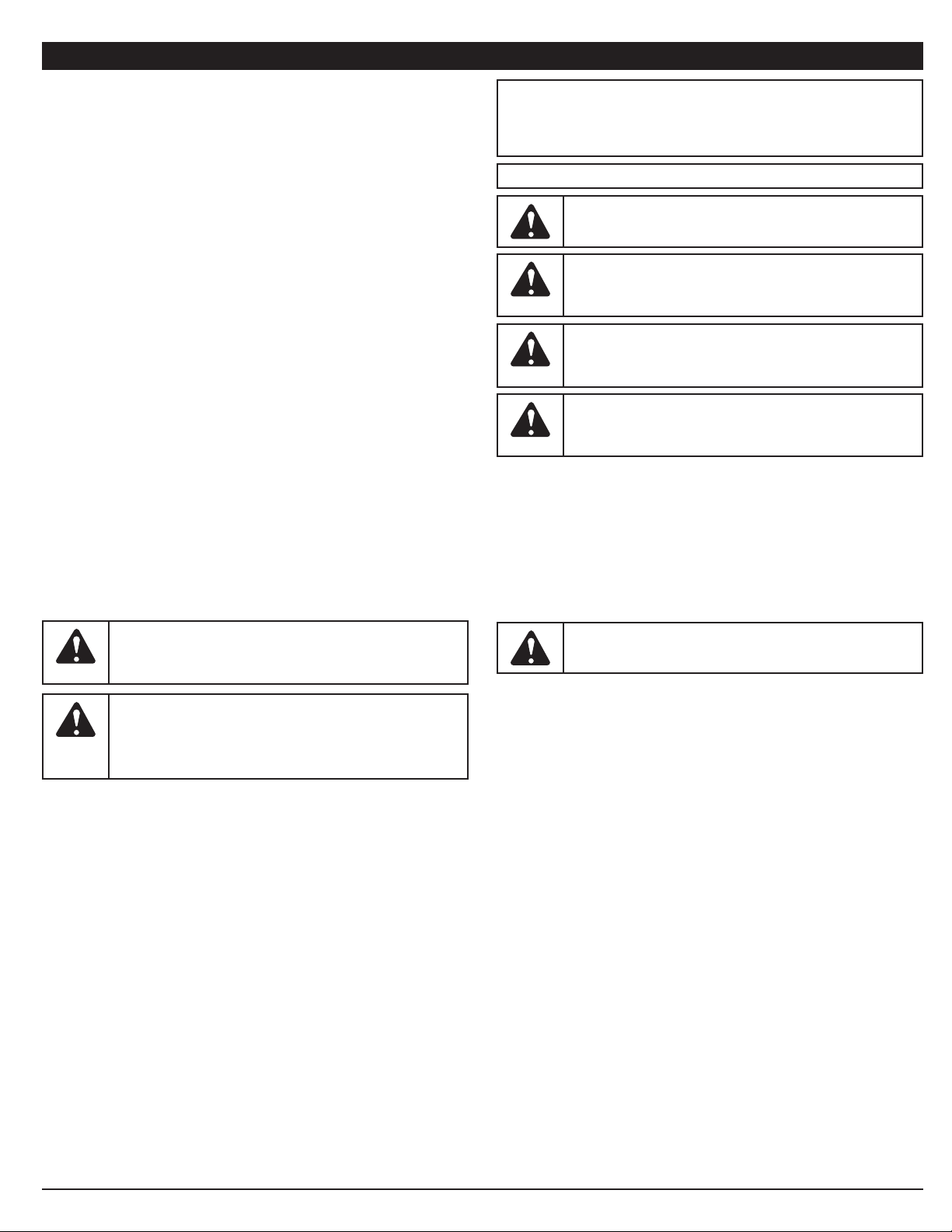
SAFETY ALERT:
Indicates danger, warning or caution.
Attention is required in order to avoid serious personal injury.
May be used in conjunction with other symbols or pictographs.
DANGER:
Failure to obey a safety warning will result in
serious injury to yourself or to others. Always follow the safety
precautions to reduce the risk of fire, electric shock and
personal injury.
WARNING:
Failure to obey a safety warning can result in
injury to yourself and others. Always follow the safety
precautions to reduce the risk of fire, electric shock and
personal injury.
CAUTION:
Failure to obey a safety warning may result in
property damage or personal injury to yourself or to others.
Always follow the safety precautions to reduce the risk of fire,
electric shock and personal injury.
SYMBOL MEANING
SPARK ARRESTOR NOTE
NOTE: For users on U.S. Forest Land and in the states of California,
Maine, Oregon and Washington. All U.S. Forest Land and the state of
California (Public Resources Codes 4442 and 4443), Oregon and
Washington require, by law that certain internal combustion engines
operated on forest brush and/or grass-covered areas be equipped with a
spark arrestor, maintained in effective working order, or the engine be
constructed, equipped and maintained for the prevention of fire. Check with
your state or local authorities for regulations pertaining to these
requirements. Failure to follow these requirements could subject you to
liability or a fine. This unit is factory equipped with a spark arrestor. If it
requires replacement, ask your LOCAL SERVICE DEALER to install the
Accessory Part #753-05169 Muffler Assembly.
WARNING:
When using the unit, you must follow the safety
rules. Please read these instructions before operating the unit
in order to ensure the safety of the operator and any
bystanders. Please keep these instructions for later use.
WARNING:
Gasoline is highly flammable, and its vapors can
explode if ignited. Take the following precautions:
CALIFORNIA PROPOSITION 65
WARNING:
Engine exhaust, some of its constituents and
certain finished components contain or emit chemicals known
to the State of California to cause cancer and birth defects or
other reproductive harm. Wash hands after handling.
Page 3
3
• Avoid accidental starting. Be in the starting position whenever pulling the
starter rope. The operator and unit must be in a stable position while
starting. Refer to Starting/Stopping Instructions.
• Use the right tool. Only use this tool for its intended purpose.
• Do not overreach. Always keep proper footing and balance.
• Always hold the unit with both hands when operating. Keep a firm grip on
both handles or grips.
• Keep hands, face, and feet at a distance from all moving parts. Do not
touch or try to stop the cutting head when it rotates.
• Do not touch the engine, gear housing or muffler. These parts get
extremely hot from operation, even after the unit is turned off.
• Do not operate the engine faster than the speed needed to cut, trim or
edge. Do not run the engine at high speed when not cutting.
• Always stop the engine when cutting is delayed or when walking from
one cutting location to another.
• If you strike or become entangled with a foreign object, stop the engine
immediately and check for damage. Do not operate before repairing
damage. Do not operate the unit with loose or damaged parts.
• Stop the unit, switch the engine to off, and disconnect the spark plug for
maintenance or repair.
• Use only original equipment manufacturer replacement parts and
accessories for this unit. These are available from your authorized service
dealer. Use of any unauthorized parts or accessories could lead to
serious injury to the user, or damage to the unit, and void your warranty.
• Keep unit clean of vegetation and other materials. They may become
lodged between the cutting head and shield.
• To reduce fire hazard, replace a faulty muffler and spark arrestor. Keep
the engine and muffler free from grass, leaves, excessive grease or
carbon build up.
OTHER SAFETY WARNINGS
• Never store a fueled unit inside a building where fumes may reach an
open flame or spark.
• Allow the engine to cool before storing or transporting. Be sure to secure
the unit while transporting.
• Store the unit in a dry area, locked up or up high to prevent unauthorized
use or damage, out of the reach of children.
• Never douse or squirt the unit with water or any other liquid. Keep
handles dry, clean and free from debris. Clean after each use, see
Cleaning and Storage instructions.
• Keep these instructions. Refer to them often and use them to instruct other
users. If you loan someone this unit, also loan them these instructions.
SAVE THESE INSTRUCTIONS
RULES FOR SAFE OPERATION
• SAFETY AND INTERNATIONAL SYMBOLS •
This operator's manual describes safety and international symbols and pictographs that may appear on this product. Read the operator's manual for complete
safety, assembly, operating and maintenance and repair information.
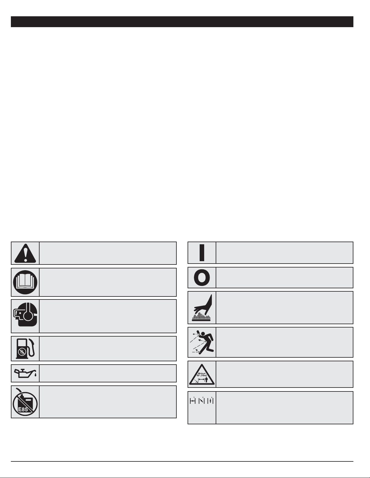
• SAFETY ALERT SYMBOL
Indicates danger, warning or caution. May be used in
conjunction with other symbols or pictographs.
• HOT SURFACE WARNING
Do not touch a hot muffler or cylinder. You may get burned.
These parts get extremely hot from operation. When turned
off, they remain hot for a short time.
• WARNING - READ OPERATOR'S MANUAL
Read the operator’s manual(s) and follow all warnings and safety
instructions. Failure to do so can result in serious injury to the
operator and/or bystanders.
• WEAR EYE AND HEARING PROTECTION
WARNING:
Thrown objects and loud noise can cause
severe eye injury and hearing loss. Wear eye protection
meeting ANSI Z87.1-1989 standards and ear protection
when operating this unit. Use a full face shield when needed.
• KEEP BYSTANDERS AWAY
WARNING: Keep all bystanders, especially children and
pets, at least 50 feet (15 m) from the operating area.
• THROWN OBJECTS AND ROTATING CUTTER CAN
CAUSE SEVERE INJURY
WARNING: Small objects can be propelled at high speed,
causing injury. Keep away from the rotating rotor.
SYMBOL MEANING
• CHOKE CONTROL
1. • FULL choke position
2. • PARTIAL choke position
3. • RUN choke position
• UNLEADED FUEL
Always use clean, fresh unleaded fuel
• ON/OFF STOP CONTROL
ON / START / RUN
• ON/OFF STOP CONTROL
OFF or STOP
SYMBOL MEANING
•OIL
Refer to operator’s manual for the proper type of oil.
• DO NOT USE E85 FUEL IN THIS UNIT
WARNING: It has been proven that fuel containing
greater than 10% ethanol will likely damage this engine and
void the warranty.
Page 4
4
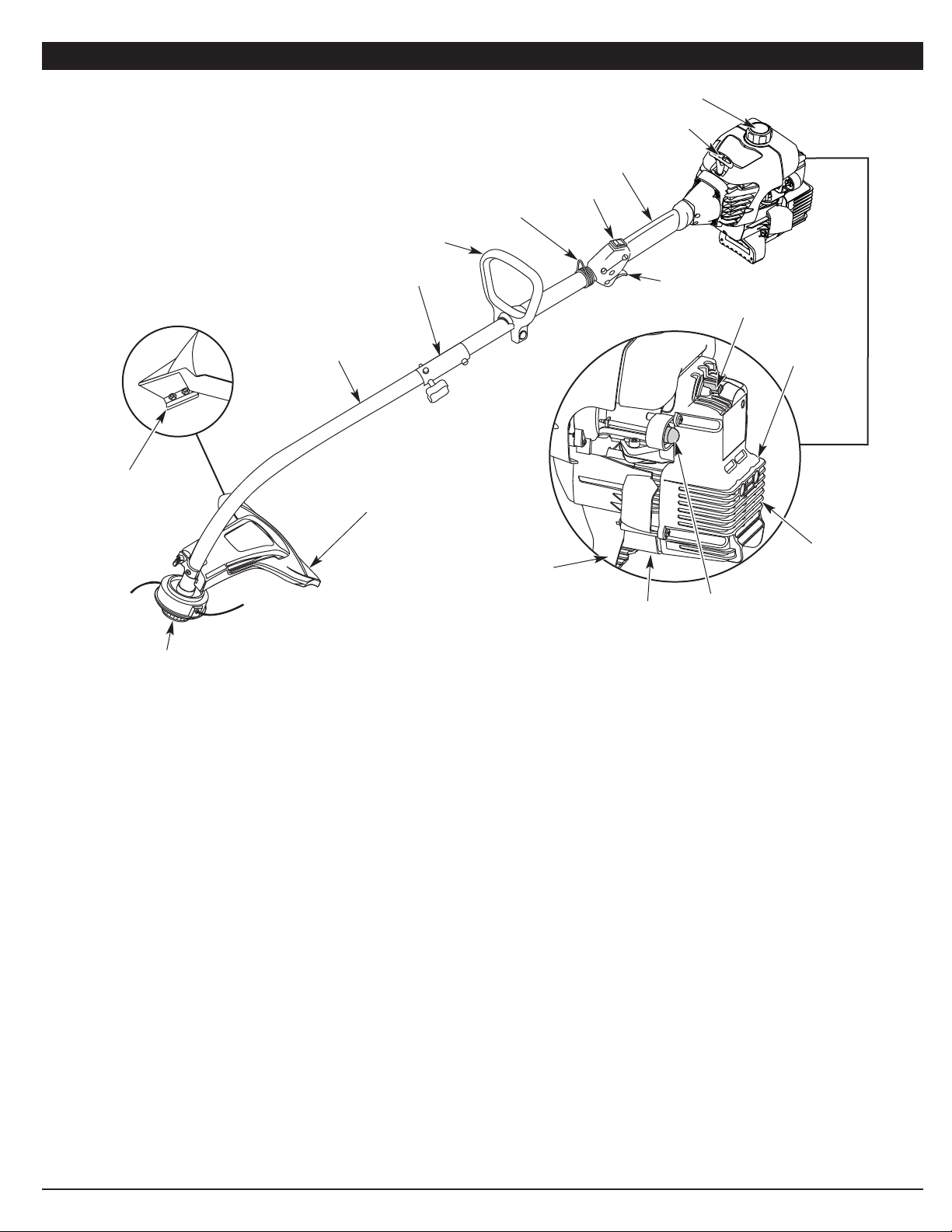
KNOW YOUR UNIT
Cutting Head Shield
Fuel Cap
Throttle
Control
D-Handle
Cutting Head
Shaft Grip
Primer Bulb
Blue Choke Lever
Spark Plug
Engine Stand
On/Off Stop Control
Shaft Housing
Starter Rope Grip
Line Cutting Blade
Muffler
EZ-Link™
Air Filter/
Muffler Cover
APPLICATIONS
As a trimmer:
• Cutting grass and light weeds
• Edging
• Decorative trimming around trees, fences, etc.
Other optional accessories may be used with this unit. Refer to Operating
the EZ-Link System for a list of add-ons.
NO TOOLS REQUIRED!
Shoulder Strap Clip
Page 5
5
INSTALL AND ADJUST THE D-HANDLE
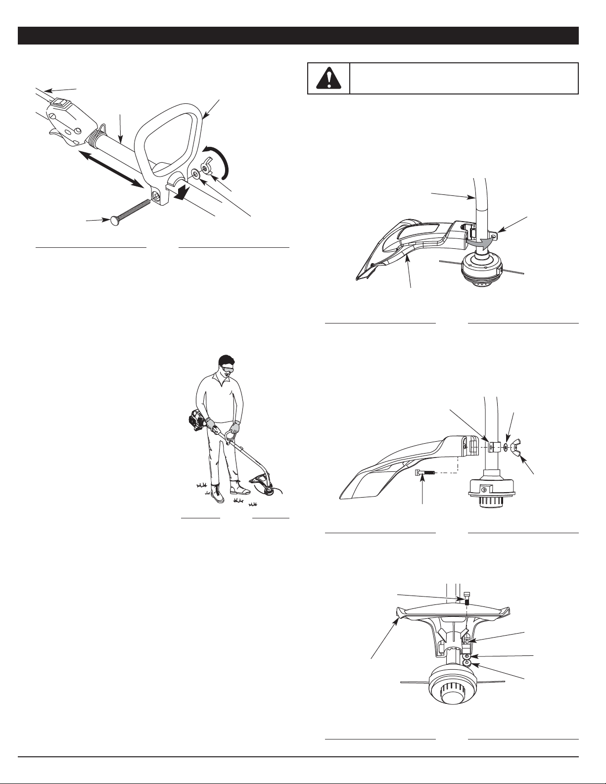
1. Push the D-handle down onto the shaft housing (Fig. 1). The squared
bolt hole in the handle is to the right.
Shaft Grip
Shaft Housing
D-Handle
Tighten
Minimum 6 inches
(15.24 cm)
Bolt
2. Insert the shoulder bolt into the squared hole in the handle and push
through. On the left side of the handle, place the washer on the bolt,
then screw the wing nut onto the bolt. Do not tighten until you make the
handle adjustment.
3. Rotate the D-handle to place the grip above the top of the shaft housing.
Place it a minimum of 6 inches (15.24 cm) from the end of the shaft grip.
4. While holding the unit in the operating position (Fig. 2), position the Dhandle to the location that provides you the best grip.
5. Tighten the wing nut until the D-handle is secure.
Fig. 1
Fig. 2
INSTALL THE CUTTING HEAD SHIELD
Use the following instructions if the cutting head shield on your unit is not
installed.
1. Place the cutting head shield onto the shaft housing. Be sure the guard
mounting bracket slides into the slot on the edge of the cutting shield.
Rotate the shield into place, counterclockwise. The holes in the guard
mounting bracket and cutting head shield will line up (Fig. 3).
Shaft Housing
Cutting Head Shield
Guard
Mounting
Bracket
Fig. 3
ASSEMBLY INSTRUCTIONS
WARNING: Never operate the trimmer without the cutting
head shield in place to prevent serious personal injury.
Washer
Guard
Mounting
Bracket
Square Bolt
Wing Nut
Fig. 4
Hole
Square Bolt
Cutting Head Shield
Washer
Fig. 5
2. From inside the cutting head shield, push the square bolt through the
hole until the threaded end protrudes through the guard mounting
bracket (Fig. 4).
3. Put the washer on the bolt, then screw the wing nut onto the bolt and
tighten. Figure 5 shows the installation process from underneath the unit.
Wing Nut
Washer
Wing Nut
Cutting Head and Shield: Underside View
Page 6
6
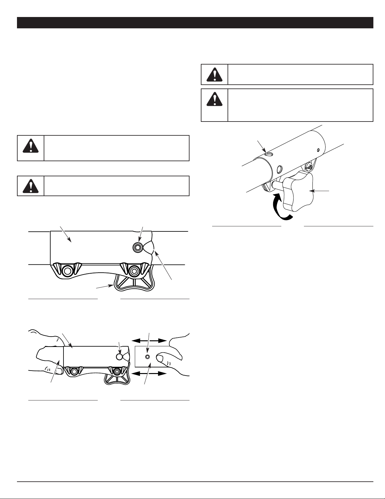
For decorative trimming /
edging with the line head
cutting, lock the release
button of the lower boom into
the 90° hole (Fig. 8).
OPERATING THE EZ-LINK™ SYSTEM
The EZ-Link™ system enables the use of these optional Add-Ons:
Mach 4® Trimmer . . . . . . . . . . . . . . . . . . . . . . . . . . . . . . . . . . . . . . . .AF720
Articulating Hedge Trimmer . . . . . . . . . . . . . . . . . . . . . . . . . . . . . . . . AH720*
Brushcutter . . . . . . . . . . . . . . . . . . . . . . . . . . . . . . . . . . . . . . . . . . . . .BC720*
Bladed Pruner . . . . . . . . . . . . . . . . . . . . . . . . . . . . . . . . . . . . . . . . . . .BP720
Blower Trimmer . . . . . . . . . . . . . . . . . . . . . . . . . . . . . . . . . . . . . . . . . .BT720*
Blower Vacuum . . . . . . . . . . . . . . . . . . . . . . . . . . . . . . . . . . . . . . . . . .BV720
Garden Cultivator . . . . . . . . . . . . . . . . . . . . . . . . . . . . . . . . . . . . . . . . GC720
Lawn Dethatcher . . . . . . . . . . . . . . . . . . . . . . . . . . . . . . . . . . . . . . . . .LD720
Lawn Edger . . . . . . . . . . . . . . . . . . . . . . . . . . . . . . . . . . . . . . . . . . . . LE720*
Pole Saw . . . . . . . . . . . . . . . . . . . . . . . . . . . . . . . . . . . . . . . . . . . . . . . PS720
Straight Shaft Trimmer . . . . . . . . . . . . . . . . . . . . . . . . . . . . . . . . . . . . SS725
Snow Thrower . . . . . . . . . . . . . . . . . . . . . . . . . . . . . . . . . . . . . . . . . . .ST720
Turbo Blower . . . . . . . . . . . . . . . . . . . . . . . . . . . . . . . . . . . . . . . . . . . . TB720
* Do NOT use this add-on with an electric powered product.
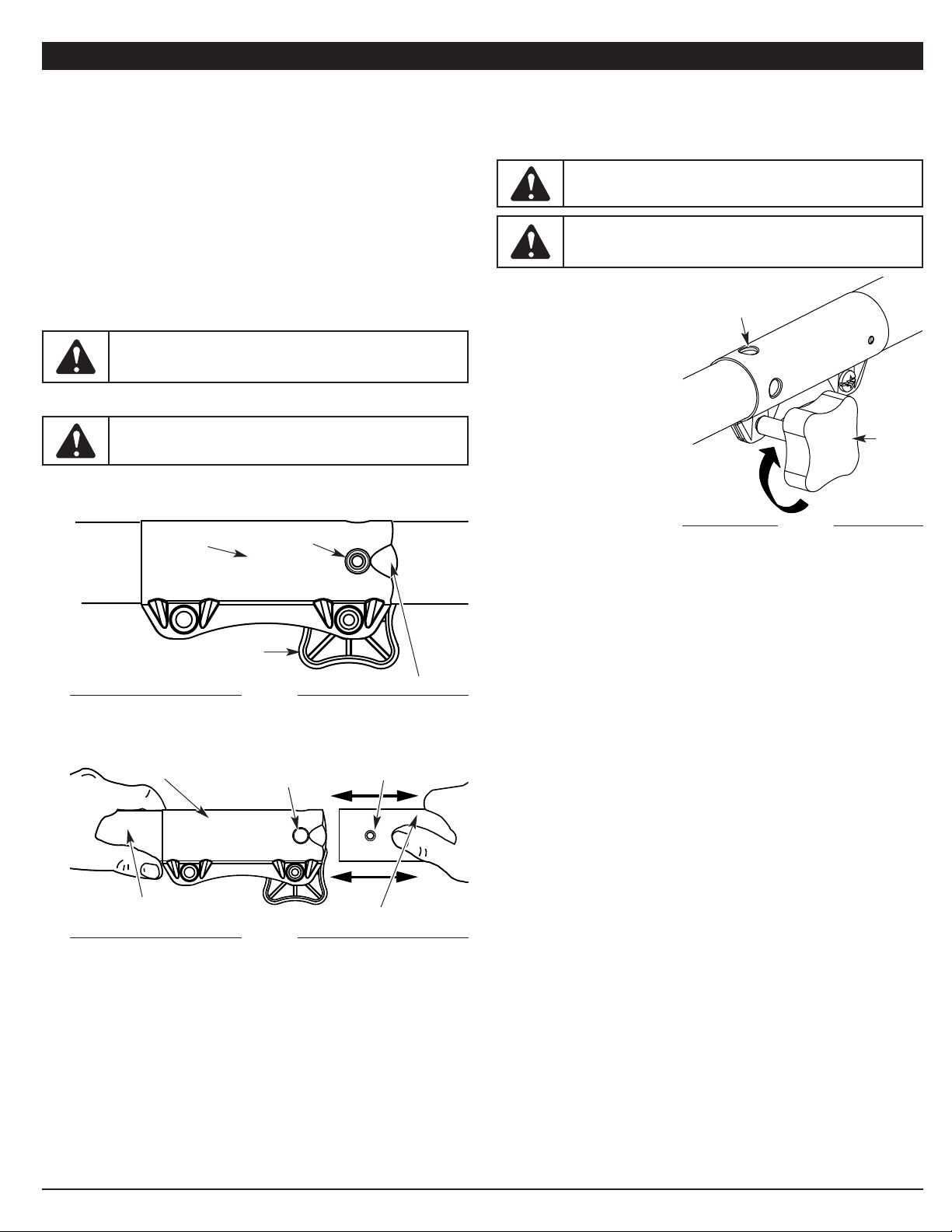
Removing the Add-On
1. Turn the knob counterclockwise to loosen (Fig. 6).
2. Press and hold the release button (Fig. 6).
Fig. 6
EZ-Link™
Coupler
Release
Button
Guide Recess
Knob
Primary Hole
Upper Shaft Housing
EZ-Link™ Coupler
2. While firmly holding the add-on, push it straight into the EZ-Link™
coupler (Fig. 7).
NOTE: Aligning the release button with the guide recess will help
installation (Fig. 6).
3. Turn the knob clockwise to tighten (Fig. 8).
Fig. 7
Fig. 8
Knob
Lower Shaft Housing
Release Button
90˚ Edge
Trimming Hole
ASSEMBLY INSTRUCTIONS
3. While firmly holding the upper shaft housing, pull the add-on straight out
of the EZ-Link™ coupler (Fig. 7).
Installing the Add-On
NOTE: To make installing or removing the add-on easier, place the unit on
the ground or on a work bench.
1. Turn the knob counterclockwise to loosen (Fig. 6).
WARNING: When using any add-on, read and understand
that add-on’s specific manual before you begin operation.
Follow all applicable safety information.
WARNING: To avoid serious personal injury and damage to
the unit, shut the unit off before removing or installing add-ons.
CAUTION: Lock the release button in the primary hole and
securely tighten the knob before operating this unit.
CAUTION: Add-ons are to be used in the primary hole only.
Using the wrong hole could lead to personal injury or damage
to the unit.
Page 7
7
OIL AND FUEL INFORMATION
OIL AND FUEL MIXING INSTRUCTIONS
Old and/or improperly mixed fuel are the main reasons for the unit not
running properly. Be sure to use fresh, clean unleaded fuel. Follow the
instructions carefully for the proper fuel/oil mixture.
Definition of Blended Fuels
Today's fuels are often a blend of gasoline and oxygenates such as ethanol,
methanol, or MTBE (ether). Alcohol-blended fuel absorbs water. As little as 1%
water in the fuel can make fuel and oil separate. It forms acids when stored.
When using alcohol-blended fuel, use fresh fuel (less than 30 days old).
Using Blended Fuels
If you choose to use a blended fuel, or its use is unavoidable, follow
recommended precautions:
• Always use the fresh fuel mix explained in your operator's manual
• Always agitate the fuel mix before fueling the unit
• Drain the tank and run the engine dry before storing the unit
Using Fuel Additives
The bottle of 2-cycle oil that came with this unit contains a fuel additive that
will help inhibit corrosion and minimize the formation of gum deposits. Using
the 2-cycle oil included with this unit is recommended. If unavailable, use a
good 2-cycle oil designed for air-cooled engines along with a fuel additive,
such as STA-BIL® Gas Stabilizer or an equivalent. Add 0.8 oz. (23 ml) of fuel
additive per gallon of fuel according to the instructions on the container.
NEVER add fuel additives directly to the unit's fuel tank.
Thoroughly mix the proper ratio of 2-cycle engine oil with unleaded gasoline in
a separate fuel can. Use a 40:1 fuel/oil ratio. Do not mix them directly in the
engine fuel tank. See the table below for specific gas and oil mixing ratios.
NOTE: One gallon (3.8 liters) of unleaded gasoline mixed with one 3.2 oz.
(95 ml) bottle of 2-cycle oil makes a 40:1 fuel/oil ratio.
NOTE: Dispose of the old fuel/oil mix in accordance with federal, state
and local regulations.
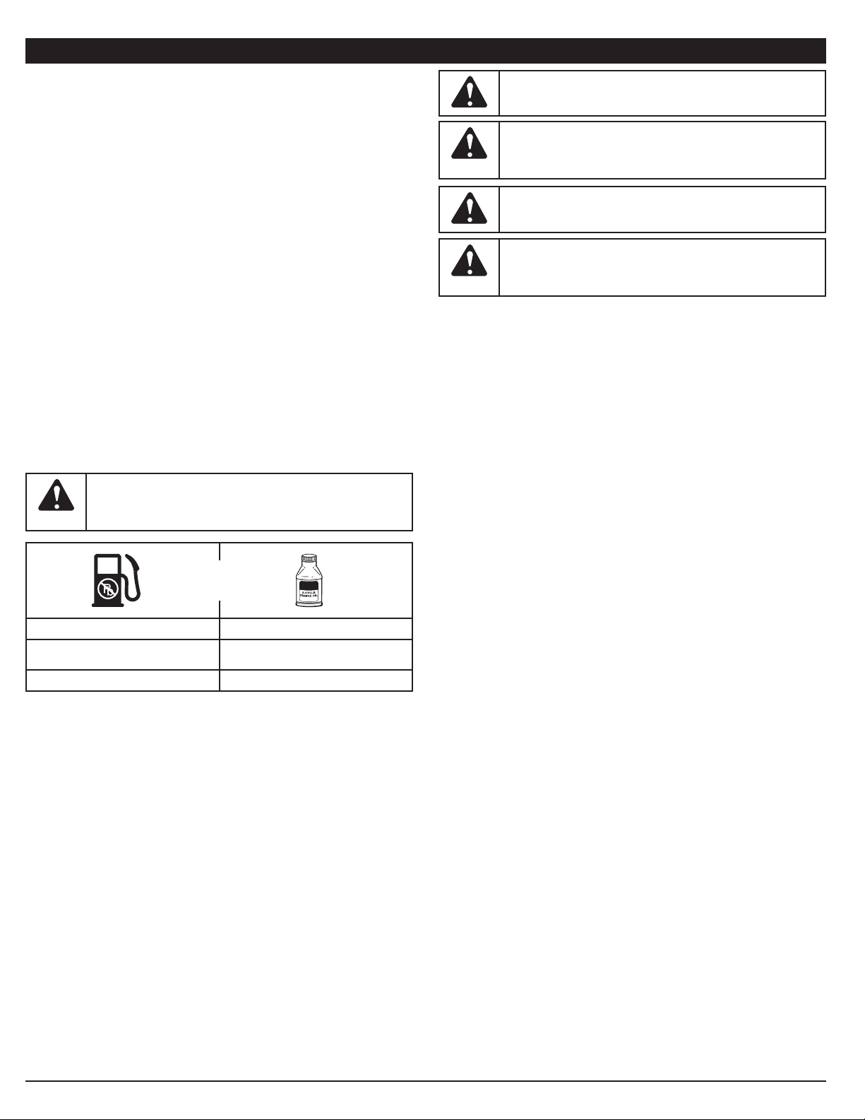
MIXING RATIO - 40:1
UNLEADED GAS* 2 CYCLE OIL
1 GALLON US
(3.8 LITERS)
3.2 FL. OZ.
(95 ML)
1 LITER 25 ML
+
CAUTION: For proper engine operation and maximum
reliability, pay strict attention to the oil and fuel mixing
instructions on the 2-cycle oil container. Using improperly
mixed fuel can severely damage the engine.
*WARNING:
DO NOT USE E85 FUEL IN THIS UNIT. It
has been proven that fuel containing greater than 10% ethanol
will likely damage this engine and void the warranty.
WARNING: Gasoline is extremely flammable. Ignited vapors
may explode. Always stop the engine and allow it to cool
before filling the fuel tank. Do not smoke while filling the tank.
Keep sparks and open flames at a distance from the area.
WARNING: Remove fuel cap slowly to avoid injury from fuel
spray. Never operate the unit without the fuel cap securely in
place.
WARNING: Add fuel in a clean, well ventilated outdoor area.
Wipe up any spilled fuel immediately. Avoid creating a source
of ignition for spilt fuel. Do not start the engine until fuel vapors
dissipate.
Page 8
8
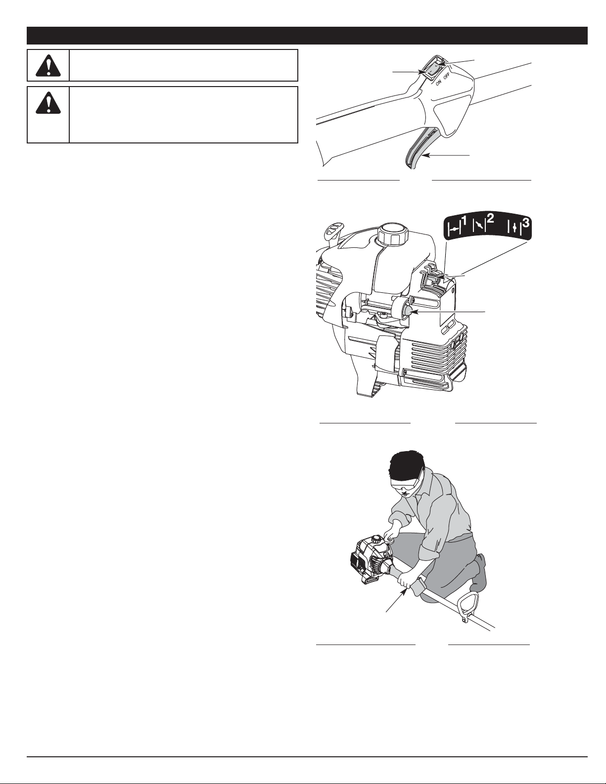
Fig. 9
Throttle Control
Fig. 11
Starting Position
On ( I )
Off (O)
Throttle Control
Fig. 10
Blue Choke Lever
Primer Bulb
STARTING INSTRUCTIONS
1. Mix fuel with oil. See Oil and Fuel Mixing Instructions.
2. Fill the fuel tank with fresh, clean fuel mix. Refer to Fueling the Unit.
NOTE: There is no need to turn the unit on. The On/Off Stop Control is in
the ON ( I ) position at all times (Fig. 9).
3. Fully press and release the primer bulb 10 times, slowly. Some amount of
fuel should be visible in the primer bulb and fuel lines (Fig. 10). If fuel can
not be seen in the bulb, press and release the bulb until fuel is visible.
4. Place the blue choke lever in Position 1 (Fig. 10).
5. Crouch in the starting position (Fig. 11), squeeze the throttle control, and
pull the starter rope out with a controlled and steady motion 5 times.
6. Place the blue choke lever in Position 2 (Fig. 10)
7. While squeezing the throttle control, pull the starter rope out with a
controlled and steady motion 3-5 times.
8. Keep the throttle squeezed and allow the engine to warm up for 30 to 60
seconds.
9. Continue squeezing the throttle control, move the blue choke lever to
Position 3 (Fig. 10) and continue warming the engine for an additional 60
seconds. The unit may be used during this time.
NOTE: Unit is properly warmed up when engine accelerates without hesitation.
NOTE: The engine may take longer to warm up and reach maximum
operating speed at colder temperatures.
IF... the engine hesitates, return the blue choke lever to Position 2 (Fig. 10)
and continue warm-up.
IF... the engine does not start, go back to step 3.
IF... the engine fails to start after a few attempts, place the blue choke
lever in Position 3 and squeeze the throttle control. Pull the starter
rope out with a controlled and steady motion 3 to 8 times. The
engine should start. If not, repeat.
IF WARM... If the engine is already warm, start the unit with the blue choke
lever in Position 2. After the unit starts, move the blue choke lever
to Position 3.
STOPPING INSTRUCTIONS
1. Release the throttle control and allow the engine to cool down by idling.
2. Press and hold the On/Off Stop Control in the OFF (O) position until the
unit comes to a complete stop (Fig. 9).
STARTING/STOPPING INSTRUCTIONS
WARNING:
Operate this unit only in a well-ventilated
outdoor area. Carbon monoxide exhaust fumes can be lethal in
a confined area.
WARNING: Avoid accidental starting. Make sure you are in
the starting position when pulling the starter rope (Fig. 11). To
avoid serious injury, the operator and unit must be in a stable
position while starting.
Make sure that any Add-On item is installed correctly and
secure before starting the unit.
Page 9
9
OPERATING INSTRUCTIONS
Fig. 14
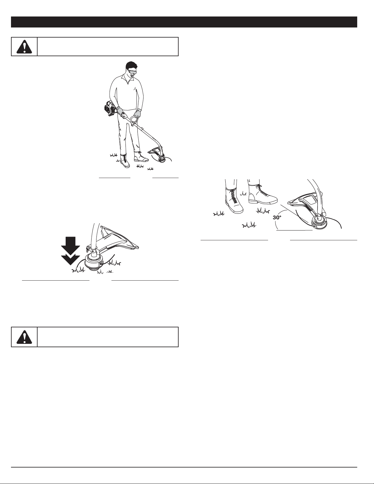
DECORATIVE TRIMMING
Decorative trimming is accomplished by removing all vegetation around
trees, posts, fences and more. Rotate the whole unit so that the cutting head
is at a 30° angle to the ground (Fig. 14).
Some line breakage will occur from:
• Entanglement with foreign matter
• Normal line fatigue
• Attempting to cut thick, stalky weeds
• Forcing the line into objects such as walls or fence posts
ADJUSTING TRIMMING LINE LENGTH
The Bump Head™ cutting head allows you to release trimming line without
stopping the engine. To release more line, lightly tap the cutting head on the
ground (Fig. 13) while operating the trimmer at high speed.
NOTE: Always keep the trimming line fully extended. Line release
becomes more difficult as the cutting line becomes shorter.
Fig. 13
Each time the head is bumped, about 1 inch (25.4 mm) of trimming line is
released. A blade in the cutting head shield will cut the line to the proper
length if any excess line is released. For best results, tap the Bump Head™
on bare ground or hard soil. If line release is attempted in tall grass, the
engine may stall.
NOTE: Do not rest the Bump Head™ on the ground while the unit is running.
HOLDING THE TRIMMER
Before operating the unit, stand in the
operating position (Fig. 12). Check for
the following:
• The operator is wearing eye
protection and proper clothing
• With a slightly-bent right arm, the
operator’s right hand is holding the
shaft grip
• The operator’s left arm is straight, with
the left hand holding the D-handle
• The unit is at waist level
• The cutting head is parallel to the
ground and easily contacts the grass
without the need to bend over
Fig. 12
TIPS FOR BEST TRIMMING RESULTS
• For best trimming results, operate unit at full throttle.
• Keep the cutting head parallel to the ground.
• Do not force the cutting head. Allow the tip of the line to do the cutting,
especially along walls. Cutting with more than the tip will reduce cutting
efficiency and may overload the engine.
• Cut grass over 8 inches (200 mm) by working from top to bottom in small
increments to avoid premature line wear or engine drag.
• Cut from right to left whenever possible. Cutting to the left improves the
unit's cutting efficiency. Clippings are thrown away from the operator.
• Slowly move the trimmer into and out of the cutting area at the desired
height. Move either in a forward-backward or side-to-side motion. Cutting
shorter lengths produces the best results.
• Trim only when grass and weeds are dry.
• The life of your cutting line is dependent upon:
— Proper adherence of trimming techniques (explained above)
— What vegetation is cut
— Where vegetation is cut
For example, the line will wear faster when trimming against a foundation
wall as opposed to trimming around a tree.
WARNING: Always wear eye, hearing, foot and body
protection to reduce the risk of injury when operating this unit.
CAUTION:
Do not remove or alter the line cutting blade
assembly. Excessive line length will make the clutch overheat.
This may lead to serious personal injury or damage to the unit.
Page 10
10
MAINTENANCE SCHEDULE
Perform these required maintenance procedures at the frequency stated in
the table. These procedures should also be a part of any seasonal tune-up.
NOTE: Some maintenance procedures may require special tools or skills.
If you are unsure about these procedures take your unit to any
non-road engine repair establishment, individual or authorized
service dealer.
NOTE: Maintenance, replacement, or repair of the emission control
devices and system may be performed by any non-road engine
repair establishment, individual or authorized service dealer.
NOTE: Please read the California/EPA statement that came with the unit for
a complete listing of terms and coverage for the emissions control
devices, such as the spark arrestor, muffler, carburetor, etc.
FREQUENCY MAINTENANCE REQUIRED REFER TO
Before starting engine Fill fuel tank with fresh fuel* p. 7
Every 10 hours Clean and re-oil air filter p. 12
Every 25 hours Check spark plug condition and gap p. 13
Indexing Teeth
Fig. 16
Fig. 17
LINE INSTALLATION
This section covers both SplitLine™ and standard single line installation.
Always use original equipment manufacturer 0.095 in. (2.41 mm)
replacement line. Other types of line may make the engine overheat or fail.
There are two methods to replace the trimming line:
• Wind the inner reel with new line
• Install a prewound inner reel
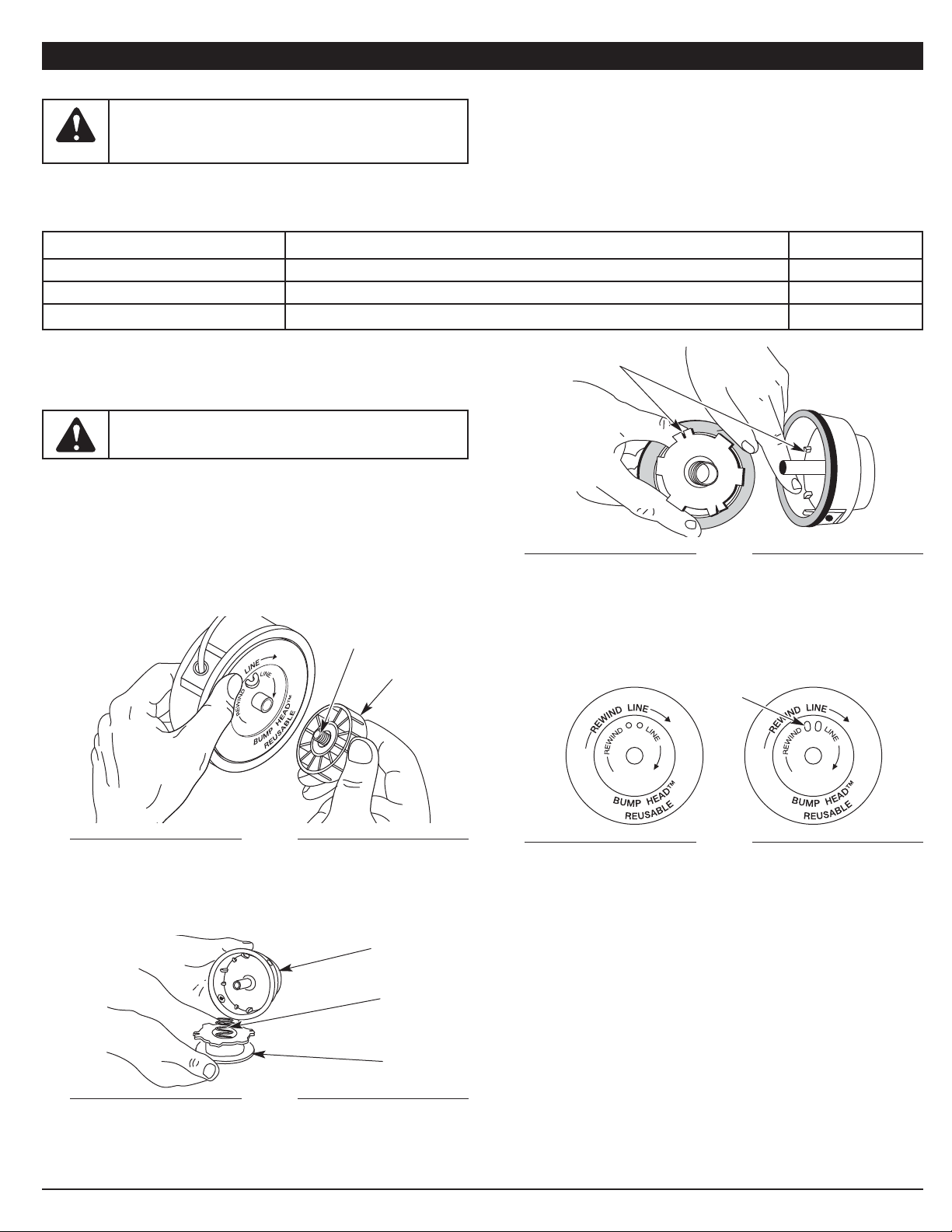
Winding the Existing Inner Reel
1. Hold the outer spool with one hand and unscrew the bump knob
counterclockwise (Fig. 15). Inspect the bolt inside the bump knob to
make sure it moves freely. Replace the bump knob if damaged.
2. Remove the inner reel from the outer spool (Fig. 16).
3. Remove the spring from the inner reel (Fig. 16).
4. Use a clean cloth to clean the inner reel, spring, shaft and inner surface
of the outer spool.
5. Check the indexing teeth on the inner reel and outer spool for wear (Fig. 17).
If necessary, remove burrs or replace the reel and spool.
Bump Knob
Bolt
Fig. 15
MAINTENANCE AND REPAIR INSTRUCTIONS
WARNING:
To prevent serious injury, never perform
maintenance or repairs with unit running. Always service and
repair a cool unit. Disconnect the spark plug wire to ensure
that the unit cannot start.
WARNING: Never use metal-reinforced line, wire, chain or
rope. These can break off and become dangerous projectiles.
NOTE: Always use the correct line length when installing trimming line on
the unit. The line may not release properly if the line is too long.
For Use with
Single Line ONLY
Fig. 18
NOTE: SplitLine™ can only be used with the inner reel with the slotted
holes. Single line can be used on either type of inner reel. Use
Figure 18 to identify the inner reel you have.
Outer Spool
Spring
Inner Reel
For Use with SplitLine™
or Single Line
Slotted
Holes
Page 11
11
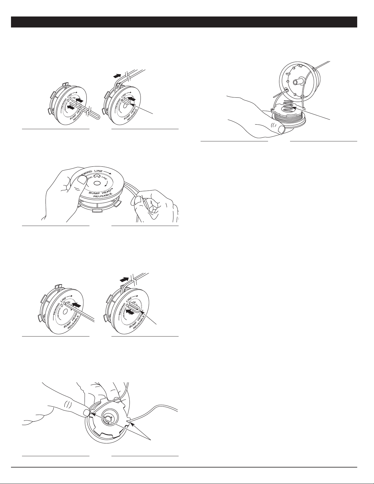
Single Line Installation
Go To Step 8 for SplitLine™ Installation
6. Take approximately 18 feet (5.4 m) of new trimming line, loop it into two
equal lengths. Insert each end of the line through one of the two holes in
the inner reel (Fig. 19). Pull the line through the inner reel so that the loop
is as small as possible.
7. Wind the lines in tight even layers, onto the reel (Fig. 20). Wind the line in
the direction indicated on the inner reel. Place your index finger between
the two lines to stop the lines from over-lapping. Do not overlap the ends
of the line. Proceed to step 11.
SplitLine™ Installation
8. Take approximately 9 feet (3 m) of new trimming line. Insert one end of
the line through one of the two holes in the inner reel (Fig. 21). Pull the
line through the inner reel until only about 4 inches is left out.
9. Insert the end of the line into the open hole in the inner reel and pull the
line tight to make the loop as small as possible (Fig. 21).
13. Insert the ends of the line through the eyelets in the outer spool and
place inner reel with the spring inside the outer spool (Fig. 23). Push the
inner reel and outer spool together. While holding the inner reel and
outer spool, grasp the ends and pull firmly to release the line from the
holding slots in the reel.
10. Before winding, split the line back about 6 inches.
11. Wind the line in tight even layers in the direction indicated on the inner reel.
NOTE: Failure to wind the line in the direction indicated will cause the
cutting head to operate incorrectly.
12. Insert the ends of the line into the two holding slots (Fig. 22).
MAINTENANCE AND REPAIR INSTRUCTIONS
INSTALLING A PREWOUND REEL
1. Hold the outer spool with one hand and unscrew the bump knob
clockwise (Fig. 15). Inspect the bolt inside the bump knob to make sure
it moves freely. Replace the bump knob if damaged.
2. Remove the old inner reel from the outer spool (Fig. 16).
3. Remove the spring from the old inner reel (Fig. 16).
4. Place the spring in the new inner reel.
NOTE: The spring must be assembled on the inner reel before reassembling
the cutting head.
5. Insert the ends of the line through the eyelets in the outer spool (Fig. 23).
6. Place the new inner reel inside the outer spool. Push the inner reel and outer
spool together. While holding the inner reel and outer spool, grasp the ends
and pull firmly to release the line from the holding slots in the spool.
7. Hold the inner reel in place and install the bump knob by turning
clockwise. Tighten securely.
NOTE: The spring must be assembled on the inner reel before reassembling
the cutting head.
14. Hold the inner reel in place and install the bump knob by turning
counterclockwise. Tighten securely.
Fig. 19
Fig. 21
Fig. 22
Fig. 23
Loop
Spring
Holding Slots
Loop
Fig. 20
Page 12
12
Cleaning the Air Filter
Failure to maintain your air filter properly can result in poor performance or
can cause permanent damage to your engine.
1. Remove the air filter/muffler cover. Refer to Removing the Air Filter/
Muffler Cover.
2. Turn cover over and look inside to locate the air filter. Remove the air
filter from inside the air filter/muffler cover (Fig. 25).
Fig. 25
Air Filter
Inside Muffler C over
MAINTENANCE AND REPAIR INSTRUCTIONS
3. Wash the filter in detergent and water. Rinse the filter thoroughly.
Squeeze out excess water. Allow it to dry completely.
4. Apply enough clean SAE 30 oil to lightly coat the filter.
5. Squeeze the filter to spread and remove excess oil.
6. Replace the air filter inside the air filter/muffler cover (Fig. 25).
NOTE: Operating the unit without the air filter and air filter/muffler cover
assembly will VOID the warranty.
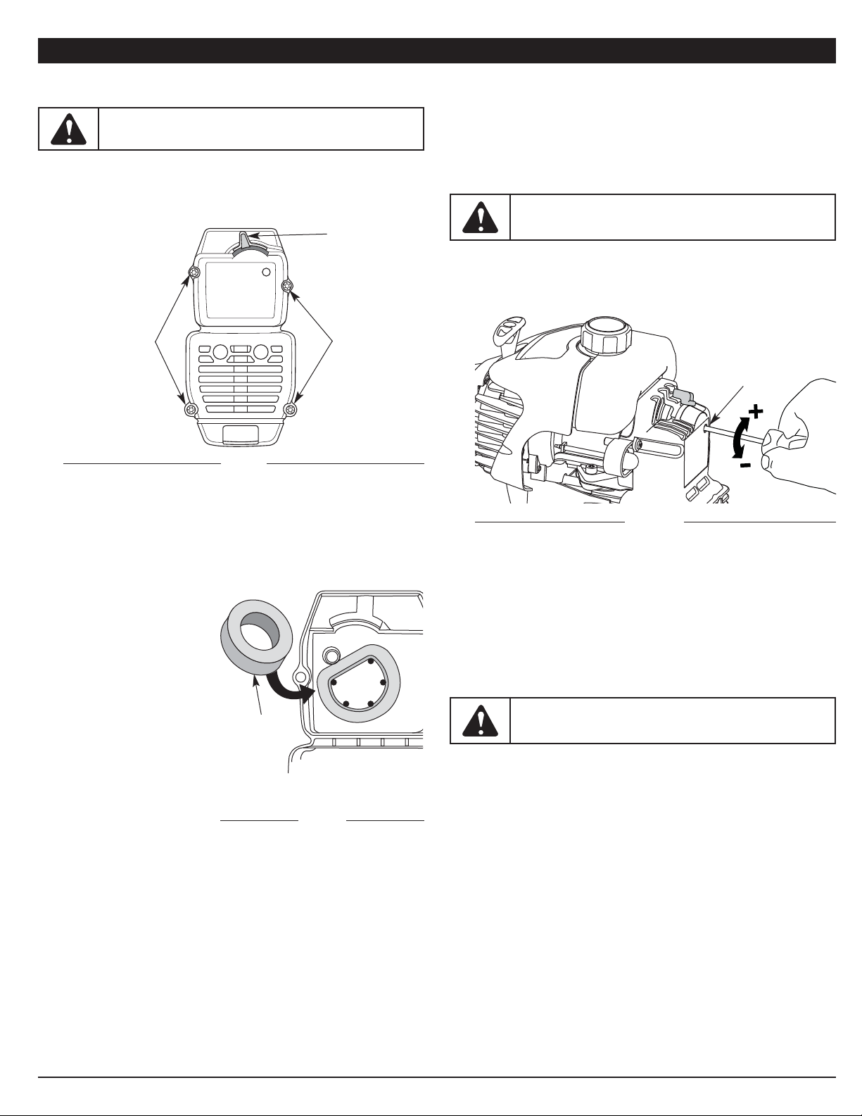
Reinstalling the Air Filter/Muffler Cover
1. Place the air filter/muffler cover over the back of the carburetor and
muffler. Align the screw holes.
2. Insert the four (4) screws into the holes in the air filter/muffler cover (Fig. 24)
and tighten.
Do not over tighten.
Fig. 24
Screws
Screws
Blue Choke Lever
AIR FILTER MAINTENANCE
Removing the Air Filter/Muffler Cover
1. Place the blue choke lever in Position 2.
2. Remove the four (4) screws securing the air filter/muffler cover (Fig. 24).
Use a flat blade or T20 Torx bit screwdriver.
3. Pull the cover from the engine. Do not force.
WARNING: To avoid serious personal injury, always turn
your unit off and allow it to cool before you clean or service it.
Fig. 26
Idle Speed Screw
IDLE SPEED ADJUSTMENT
The idle speed of the engine is adjustable through the air filter/muffler cover
(Fig. 26).
NOTE: Careless adjustments can seriously damage your unit. An
authorized service dealer should make carburetor adjustments.
If, after checking the fuel mixture and cleaning the air filter, the engine still
will not idle, adjust the idle speed screw as follows:
1. Start the engine and let it run at a high idle for a minute to warm up.
Refer to Starting/Stopping Instructions.
2. Release the throttle trigger and let the engine idle. If the engine stops,
insert a small Phillips or flat blade screwdriver into the hole in the air
filter/muffler cover (Fig. 26). Turn the idle speed screw in, clockwise,
1/8 of a turn at a time (as needed) until the engine idles smoothly.
NOTE: The cutting head should not rotate when the engine idles.
3. If the cutting head rotates when the engine idles, turn the idle speed
screw counterclockwise 1/8 of a turn at a time (as needed), to reduce
idle speed.
Checking the fuel mixture, cleaning the air filter, and adjusting the idle speed
should solve most engine problems.
If not and all of the following are true:
• The engine will not idle
• The engine hesitates or stalls on acceleration
• There is a loss of engine power
Have the carburetor adjusted by an authorized service dealer.
WARNING: The cutting head may spin during idle speed
adjustments. Wear protective clothing and observe all safety
instructions to prevent serious personal injury.
WARNING: To prevent serious personal injury, make sure
the cutting head has stopped rotating before you turn it off and
set it down.
Page 13
13
MAINTENANCE AND REPAIR INSTRUCTIONS
CLEANING
Use a small brush to clean off the outside of the unit. Do not use strong
detergents. Household cleaners that contain aromatic oils such as pine and
lemon, and solvents such as kerosene, can damage plastic housing or
handle. Wipe off any moisture with a soft cloth.
STORAGE
• Never store the unit with fuel in the tank where fumes may reach an open
flame or spark.
• Allow the engine to cool before storing.
• Store the unit locked up to prevent unauthorized use or damage.
• Store the unit in a dry, well-ventilated area.
• Store the unit out of the reach of children.
Short Term Storage (1-2 weeks)
1. Store the unit in a horizontal position. If this is not possible, store the unit
vertically with the engine at the top.
Long Term Storage
If the unit will be stored for an extended time, use the following storage
procedure:
1. Drain all fuel from the fuel tank into a container with the same 2-cycle fuel
mixture. Do not use fuel that has been stored for more than 30 days. Dispose
of the old fuel/oil mix in accordance with federal, state and local regulations.
2. Start the engine and allow it to run until it stalls. This ensures that all fuel
has been drained from the carburetor.
3. Allow the engine to cool. Remove the spark plug and put 5 drops of high
quality motor oil into the cylinder. Pull the starter rope slowly to distribute
the oil. Reinstall the spark plug.
NOTE: Remove the spark plug and drain all of the oil from the cylinder
before attempting to start the trimmer after storage.
4. Thoroughly clean the unit and inspect it for any loose or damaged parts.
Repair or replace damaged parts and tighten loose screws, nuts or bolts.
The unit is ready for storage.
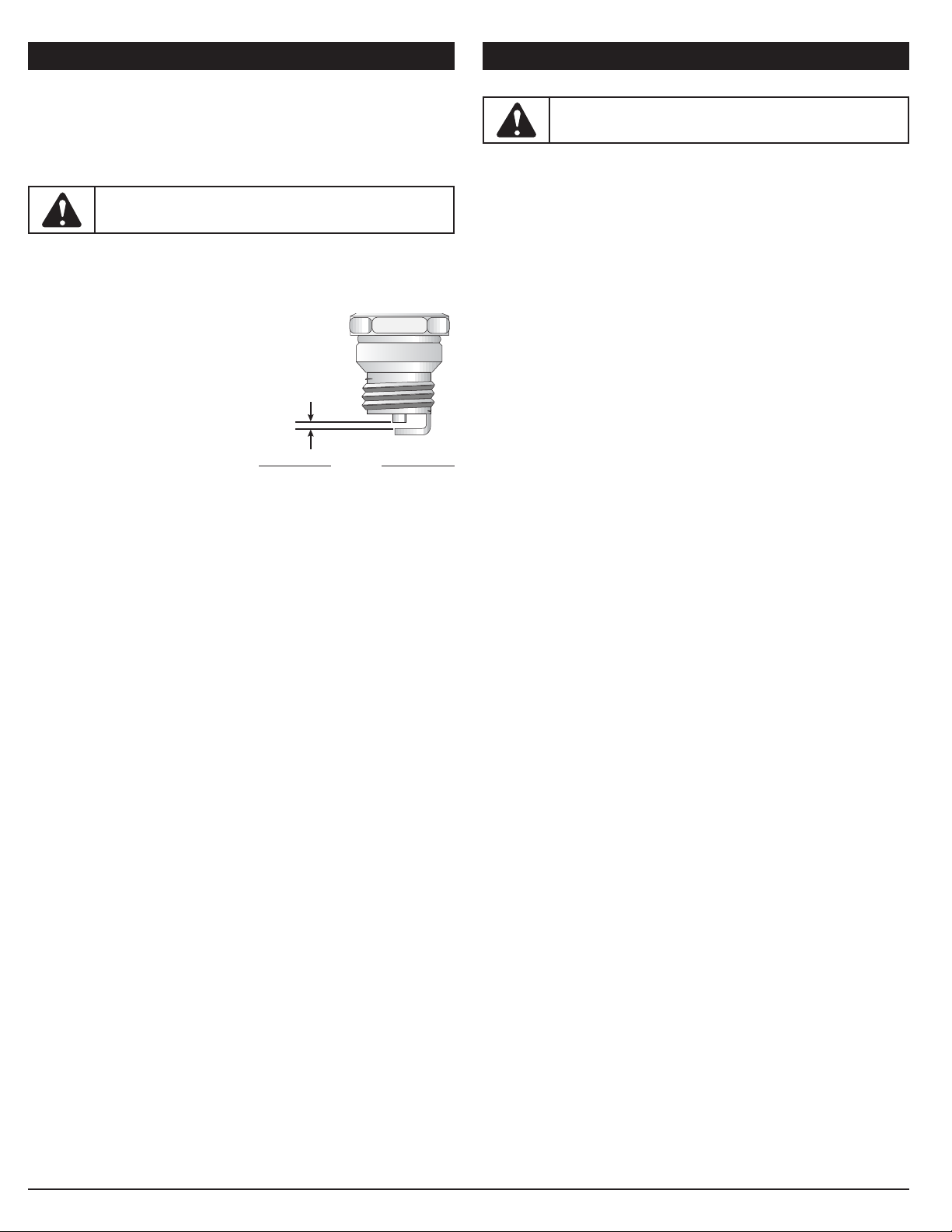
REPLACING THE SPARK PLUG
Use a #791-610311B spark plug, a Champion
®
ref. # RDJ7Y spark plug, or
equivalent. The correct air gap is 0.025 inch (0.635 mm).
1. Stop the engine and allow it to cool. Grasp the plug wire firmly and pull
the boot from the spark plug.
2. Clean around the spark plug. Remove the spark plug from the cylinder
head by turning a 5/8 in. socket counterclockwise.
3. Replace a cracked, fouled or dirty spark plug. Set the air gap at 0.025 in.
(0.635 mm) using a feeler gauge (Fig. 27).
4. Install a correctly-gapped spark plug in the cylinder head. Tighten by
turning the 5/8-inch socket clockwise until snug.
If using a torque wrench, torque to:
110-120 in.•lb. (12.3-13.5 N•m)
Do not over tighten.
0.025 in.
(0.635 mm)
Fig. 27
WARNING:
Do not sand blast, scrape or clean electrodes.
Grit in the engine could damage the cylinder.
WARNING: To avoid serious personal injury, always turn
your unit off and allow it to cool before you clean or service it.
CLEANING AND STORAGE
Page 14

CAUSE ACTION
14
TROUBLESHOOTING
If further assistance is required, contact your authorized service dealer.
Air filter is plugged Replace or clean the air filter
Old or improperly mixed fuel Drain fuel tank and add fresh fuel mixture
Improper idle speed Adjust according to the Idle Speed Adjustment section
Empty fuel tank Fill fuel tank with properly mixed fuel
Primer bulb wasn't pressed enough Press primer bulb fully and slowly 10 times
Engine is flooded Place blue choke lever in position 3, squeeze the trigger and pull the starter rope
Old or improperly mixed fuel Drain fuel tank and add fresh fuel mixture
Fouled spark plug Replace or clean the spark plug
Old or improperly mixed fuel Drain fuel tank and add fresh fuel mixture
Fouled spark plug Replace or clean the spark plug
Old or improperly mixed fuel Drain fuel tank and add fresh fuel mixture
Cutting head bound with grass Stop the engine and clean the cutting head
Dirty air filter Clean or replace the air filter
Cutting head bound with grass Stop the engine and clean the cutting head
Cutting head out of line Refill with new line
Inner reel bound up Replace the inner reel
Cutting head dirty Clean inner reel and outer spool
Line welded Disassemble, remove the welded section and rewind
Line twisted when refilled Disassemble and rewind the line
Not enough line is exposed Push the bump knob and pull out line until 4 inches (102 mm) of line is
outside of the cutting head
Oil, cleaner or lubricant in cutting head Clean and thoroughly dry the cutting head
ENGINE WILL NOT START
ENGINE WILL NOT IDLE
ENGINE WILL NOT ACCELERATE
ENGINE LACKS POWER OR STALLS WHEN CUTTING
CUTTING ATTACHMENT WILL NOT ADVANCE LINE
CUTTING LINE ADVANCES UNCONTROLLABLY
Page 15

15
ENGINE*
* All specifications are based on the latest product information available at the time of printing. We reserve the right to make changes at any time without notice.
Engine Type . . . . . . . . . . . . . . . . . . . . . . . . . . . . . . . . . . . . . . . . . . . . . . . . . . . . . . . . . . . . . . . . . . . . . . . . . . . . . . . . . . . . . . . . . . . . . . . . . . . Air-Cooled, 2-Cycle
Stroke . . . . . . . . . . . . . . . . . . . . . . . . . . . . . . . . . . . . . . . . . . . . . . . . . . . . . . . . . . . . . . . . . . . . . . . . . . . . . . . . . . . . . . . . . . . . . . . . . . . . . . . . 1.25 in. (31.75 mm)
Displacement . . . . . . . . . . . . . . . . . . . . . . . . . . . . . . . . . . . . . . . . . . . . . . . . . . . . . . . . . . . . . . . . . . . . . . . . . . . . . . . . . . . . . . . . . . . . . . . . . . . . . 1.9 cu in. (31 cc)
Clutch Type . . . . . . . . . . . . . . . . . . . . . . . . . . . . . . . . . . . . . . . . . . . . . . . . . . . . . . . . . . . . . . . . . . . . . . . . . . . . . . . . . . . . . . . . . . . . . . . . . . . . . . . . . . . Centrifugal
Idle Speed RPM. . . . . . . . . . . . . . . . . . . . . . . . . . . . . . . . . . . . . . . . . . . . . . . . . . . . . . . . . . . . . . . . . . . . . . . . . . . . . . . . . . . . . . . . . . . . . . . . . . 2,600 - 3,600 rpm
Operating RPM . . . . . . . . . . . . . . . . . . . . . . . . . . . . . . . . . . . . . . . . . . . . . . . . . . . . . . . . . . . . . . . . . . . . . . . . . . . . . . . . . . . . . . . . . . . . . . . . . . . . . . . 6,500+ rpm
Ignition Type . . . . . . . . . . . . . . . . . . . . . . . . . . . . . . . . . . . . . . . . . . . . . . . . . . . . . . . . . . . . . . . . . . . . . . . . . . . . . . . . . . . . . . . . . . . . . . . . . . . . . . . . . . . Electronic
Ignition Switch . . . . . . . . . . . . . . . . . . . . . . . . . . . . . . . . . . . . . . . . . . . . . . . . . . . . . . . . . . . . . . . . . . . . . . . . . . . . . . . . . . . . . . . . . . . . . . . . . . . . . Rocker Switch
Spark Plug Gap . . . . . . . . . . . . . . . . . . . . . . . . . . . . . . . . . . . . . . . . . . . . . . . . . . . . . . . . . . . . . . . . . . . . . . . . . . . . . . . . . . . . . . . . . . . . . . . . 0.025 in. (0.635 mm)
Lubrication . . . . . . . . . . . . . . . . . . . . . . . . . . . . . . . . . . . . . . . . . . . . . . . . . . . . . . . . . . . . . . . . . . . . . . . . . . . . . . . . . . . . . . . . . . . . . . . . . . . . . . . . Fuel/Oil Mixture
Fuel/Oil Ratio . . . . . . . . . . . . . . . . . . . . . . . . . . . . . . . . . . . . . . . . . . . . . . . . . . . . . . . . . . . . . . . . . . . . . . . . . . . . . . . . . . . . . . . . . . . . . . . . . . . . . . . . . . . . . . . 40:1
Carburetor . . . . . . . . . . . . . . . . . . . . . . . . . . . . . . . . . . . . . . . . . . . . . . . . . . . . . . . . . . . . . . . . . . . . . . . . . . . . . . . . . . . . . . . . . . . . . . . . . . Diaphragm, All-Position
Starter . . . . . . . . . . . . . . . . . . . . . . . . . . . . . . . . . . . . . . . . . . . . . . . . . . . . . . . . . . . . . . . . . . . . . . . . . . . . . . . . . . . . . . . . . . Spring Assist Starting™ Auto Rewind
Muffler . . . . . . . . . . . . . . . . . . . . . . . . . . . . . . . . . . . . . . . . . . . . . . . . . . . . . . . . . . . . . . . . . . . . . . . . . . . . . . . . . . . . . . . . . . . . . . . . . . . . . . . . . Baffled with Guard
Throttle . . . . . . . . . . . . . . . . . . . . . . . . . . . . . . . . . . . . . . . . . . . . . . . . . . . . . . . . . . . . . . . . . . . . . . . . . . . . . . . . . . . . . . . . . . . . . . . . . . . . . . Manual Spring Return
Fuel Tank Capacity . . . . . . . . . . . . . . . . . . . . . . . . . . . . . . . . . . . . . . . . . . . . . . . . . . . . . . . . . . . . . . . . . . . . . . . . . . . . . . . . . . . . . . . . . . . . . . . . . . 13 oz. (384 ml)
Drive Shaft Housing . . . . . . . . . . . . . . . . . . . . . . . . . . . . . . . . . . . . . . . . . . . . . . . . . . . . . . . . . . . . . . . . . . . . . . . . . . . . . . . . . . . . . . . . . . . Steel Tube, EZ-Link™
Throttle Control. . . . . . . . . . . . . . . . . . . . . . . . . . . . . . . . . . . . . . . . . . . . . . . . . . . . . . . . . . . . . . . . . . . . . . . . . . . . . . . . . . . . . . . . . . . . . . . . . . . Finger-Tip Trigger
Approximate Unit Weight (No fuel, with cutting head, shield, and D-handle) . . . . . . . . . . . . . . . . . . . . . . . . . . . . . . . . . . . . . . . . . . . . . . . . . . . . . . . 13 lbs. (6 kg)
Cutting Mechanism . . . . . . . . . . . . . . . . . . . . . . . . . . . . . . . . . . . . . . . . . . . . . . . . . . . . . . . . . . . . . . . . . . . . . . . . . . . . . . . . . . . . . . . . . . . . . . . . . . Bump Head™
Line Spool Diameter . . . . . . . . . . . . . . . . . . . . . . . . . . . . . . . . . . . . . . . . . . . . . . . . . . . . . . . . . . . . . . . . . . . . . . . . . . . . . . . . . . . . . . . . . . . . . . 3 inches (76.2 mm)
Trimming Line Diameter. . . . . . . . . . . . . . . . . . . . . . . . . . . . . . . . . . . . . . . . . . . . . . . . . . . . . . . . . . . . . . . . . . . . . . . . . . . . . . . . . . . . . . . . 0.095 inches (2.41 mm)
Cutting Path Diameter . . . . . . . . . . . . . . . . . . . . . . . . . . . . . . . . . . . . . . . . . . . . . . . . . . . . . . . . . . . . . . . . . . . . . . . . . . . . . . . . . . . . . . . . . . . 17 inches (43.18 cm)
SPECIFICATIONS
DRIVE SHAFT & CUTTING HEAD*
Page 16

16
MANUFACTURER’S LIMITED WARRANTY FOR:
No implied warranty, including any implied warranty of merchantability
or fitness for a particular purpose, applies after the applicable period
of express written warranty above as to the parts as identified. No
other express warranty or guaranty, whether written or oral, except as
mentioned above, given by any person or entity, including a dealer or
retailer, with respect to any product shall bind Cub Cadet During the
period of the Warranty, the exclusive remedy is repair or replacement
of the product as set forth above. (Some states do not allow limitations
on how long an implied warranty lasts, so the above limitation may not
apply to you.)
The provisions as set forth in this Warranty provide the sole and
exclusive remedy arising from the sales. Cub Cadet shall not be liable
for incidental or consequential loss or damages including, without
limitation, expenses incurred for substitute or replacement lawn care
services, for transportation or for related expenses, or for rental
expenses to temporarily replace a warranted product. (Some states do
not allow limitations on how long an implied warranty lasts, so the above
limitation may not apply to you.)
In no event shall recovery of any kind be greater than the amount of the
purchase price of the product sold. Alteration of the safety features of the
product shall void this Warranty. You assume the risk and liability for loss,
damage, or injury to you and your property and/or to others and their
property arising out of the use or misuse or inability to use the product.
This limited warranty shall not extend to anyone other than the original
purchaser, original lessee or the person for whom it was purchased as a gift.
How State Law Relates to this Warranty: This warranty gives you specific
legal rights, and you may also have other rights which vary from state to state.
To locate your nearest service dealer, dial 1-877-282-8684 in the United
States or 1-800-668-1238 in Canada.
Cub Cadet LLC
P.O. Box 361131
Cleveland, OH 44136-0019
The limited warranty set forth below is given by Cub Cadet LLC (Cub Cadet)
with respect to new merchandise purchased and used in the United States,
its possessions and territories.
Cub Cadet warrants this product against defects in material and
workmanship for a period of three (3) years commencing on the date of
original purchase and will, at its option, repair or replace, free of charge, any
part found to be defective in material or workmanship. This limited warranty
shall only apply if this product has been operated and maintained in
accordance with the Operator’s Manual furnished with the product, and has
not been subject to misuse, abuse, commercial use, neglect, accident,
improper maintenance, alteration, vandalism, theft, fire, water or damage
because of other peril or natural disaster. Damage resulting from the
installation or use of any accessory or attachment not approved by Cub
Cadet for use with the product(s) covered by this manual will void your
warranty as to any resulting damage.
This warranty is limited to ninety (90) days from the date of original retail
purchase for any Cub Cadet product that is used for rental or commercial
purposes, or any other income-producing purpose.
HOW TO OBTAIN SERVICE: Warranty service is available, WITH PROOF
OF PURCHASE THROUGH YOUR LOCAL AUTHORIZED SERVICE
DEALER. To locate the dealer in your area, visit our website at
www.cubcadet.com or www.cubcadet.ca, check for a listing in the Yellow
Pages, call 1-877-282-8684 or 1-800-668-1238 in Canada, or write to P.O.
Box 361131, Cleveland, OH 44136-0019.
This limited warranty does not provide coverage in the following cases:
A. Tune-ups - Spark Plugs, Carburetor Adjustments, Filters
B. Wear items - Bump Knobs, Outer Spools, Cutting Line, Inner Reels,
Starter Pulley, Starter Ropes, Drive Belts, Saw Chains, Guide Bars,
Cultivator Tines.
C. Cub Cadet does not extend any warranty for products sold or exported
outside of the United States of America, its possessions and territories,
except those sold through Cub Cadet’s authorized channels of export
distribution.
Cub Cadet reserves the right to change or improve the design of any Cub
Cadet Product without assuming any obligation to modify any product
previously manufactured.
Page 17

Manuel de L'utilisateur
Désherbeuse à gaz à 2-temps
ST2020
TABLE DES MATIÈRES
Service technique . . . . . . . . . . . . . . . . . . . . . . . . . . . . . . . . . . . . .17
Consignes de sécurité . . . . . . . . . . . . . . . . . . . . . . . . . . . . . . . . .18
Familiarisez-vous avec votre appareil . . . . . . . . . . . . . . . . . . . . . .20
Instructions de montage . . . . . . . . . . . . . . . . . . . . . . . . . . . . . . . .21
Informations sur l'huile et le carburant . . . . . . . . . . . . . . . . . . . . .23
Instructions de démarrage et d'arrêt . . . . . . . . . . . . . . . . . . . . . .24
Mode d'emploi . . . . . . . . . . . . . . . . . . . . . . . . . . . . . . . . . . . . . . .25
Entretien et réparations . . . . . . . . . . . . . . . . . . . . . . . . . . . . . . . . .26
Nettoyage et entreposage . . . . . . . . . . . . . . . . . . . . . . . . . . . . . .29
Tableau de dépannage . . . . . . . . . . . . . . . . . . . . . . . . . . . . . . . . .30
Caractéristiques . . . . . . . . . . . . . . . . . . . . . . . . . . . . . . . . . . . . . .31
Garantie . . . . . . . . . . . . . . . . . . . . . . . . . . . . . . . . . . . . . . . . . . . . .32
769-06373 P00 (12/10)
Toutes les informations, illustrations et spécifications contenues dans ce
manuel tiennent compte des dernières informations techniques
disponibles au moment de mettre sous presse. Nous nous réservons le
droit d'y apporter des modifications à tout moment, sans préavis.
Copyright© 2010 MTD SOUTHWEST INC., Tous droits réservés.
CONSERVEZ CES INSTRUCTIONS
NE RAMENEZ PAS CET APPAREIL CHEZ LE DÉTAILLANT. UNE
PREUVE D’ACHAT SERA EXIGÉE POUR TOUTE PRISE EN CHARGE
DANS LE CADRE DE LA GARANTIE.
Si vous éprouvez des difficultés à assembler ce produit ou si vous avez
des questions sur les commandes, l’utilisation ou l’entretien de cet
appareil, veuillez contacter le service à la clientèle : 1-877-282-8684
(E.U.) ou 1-800-668-1238 (Canada)
Des informations supplémentaires sont disponibles sur notre site web :
www.cubcadet.com (E.U.) ou www.cubcadet.ca (Canada)
Pour un entretien ou une réparation, veuillez appeler le service à la
clientèle pour obtenir une liste complète des concessionnaires agrées
près de chez vous. L’entretien de cet appareil doit être confié
exclusivement à un concessionnaire agrée pendant et après la période
de garantie. Lors de l’entretien, utilisez uniquement des pièces de
rechange identiques.
Page 18

18
LISEZ CETTE NOTICE INTEGRALEMENT AVANT D’UTILISER CET
APPAREIL :
• Lisez soigneusement cette notice. Familiarisez-vous avec les commandes
et la marche à suivre pour une bonne utilisation de l'appareil.
• N’utilisez pas cet appareil lorsque vous êtes fatigué, malade, ou sous
l’influence de l’alcool, de drogues, ou de médicaments.
• Tout enfant ou adolescent de moins de 15 ans ne doit pas utiliser cet
appareil, à moins que l'adolescent soit sous la supervision d’un adulte.
• Toutes les protections et tous les dispositifs de sécurité doivent être
installés correctement avant utilisation de l’appareil.
• Inspectez l’appareil avant utilisation. Remplacez les pièces
endommagées. Détectez les fuites de carburant éventuelles. Assurezvous que tous les accessoires sont bien en place. Remplacez les pièces
susceptibles d’être fissurées, ébréchées, ou endommagées. N’utilisez
pas cet appareil si des pièces ont du jeu ou sont endommagées.
• Inspectez la zone avec attention avant de démarrer cet appareil. Retirez tous
les débris et objets durs ou tranchants tels que du verre, les câbles, etc…
• Soyez conscient des risques de blessures à la tête, aux mains et aux pieds.
• Eloignez les enfants, les personnes à proximité et les animaux familiers
de la zone d’utilisation. Au minimum, faites reculer les enfants, les
personnes à proximité et les animaux familiers de 50 pieds (15 m) ; il
existe néanmoins un risque de projectiles pour les personnes à proximité.
Encouragez-les à porter des lunettes de sécurité. Si quelqu’un
s’approche de vous, arrêtez l’appareil immédiatement.
• Utilisez uniquement un fil de 2,41mm (0,095 pouces) de diamètre provenant
du fabricant. N’utilisez jamais de câbles, cordons ou pièces renforcées en
métal, qui peuvent céder et devenir des projectiles dangereux.
• Appuyez sur la manette des gaz et vérifiez que le régime du moteur
revienne automatiquement au ralenti. Effectuez tous les réglages et
réparations avant d’utiliser l’appareil.
ALERTES DE SECURITE POUR LES APPAREILS A ESSENCE
• Stockez uniquement le carburant dans des conteneurs prévus spécifiquement
à cet effet et approuvés pour le stockage de telles substances.
• Coupez toujours le moteur et laissez-le refroidir avant de remplir le réservoir
d’essence. Ne retirez jamais le bouchon du réservoir d’essence et ne
remplissez jamais ce dernier lorsque le moteur est chaud. Dévissez lentement
le bouchon du réservoir d’essence afin de réduire la pression avant de le
remplir. Ne fumez pas.
• Toujours mélanger et ajoutez le carburant dans un endroit bien aéré et propre,
en plein air, à l’abri des sources d’étincelles ou flammes vives. Ne fumez pas.
• Ne démarrez jamais l’appareil sans avoir bien revissé le bouchon du réservoir
d’essence.
• Évitez tout ce qui pourrait enflammer le carburant renversé. L’essence s’étant
échappée de l’appareil doit être essuyée immédiatement avant de démarrer
l'appareil. Éloignez l’appareil d’au moins 9,1 m (30 pieds) du site et de la
source du carburant avant de démarrer le moteur. Ne fumez pas.
• L'appareil ne doit pas être démarré ou utilisé à l'intérieur d'un espace ou d’un
bâtiment clos. Inhaler les fumées du pot d’échappement peut provoquer la
mort. Cet appareil doit fonctionner uniquement en extérieur, dans une zone
bien aérée.
LORS DU FONCTIONNEMENT DE L'APPAREIL
• Portez des lunettes de sécurité conformes aux normes ANSI Z87.1,
lesquelles doivent être indiquées sur les lunettes mêmes. Portez des
bouchons d’oreille et des casques antibruit lors de l’utilisation de cet
appareil. Portez un masque si l'appareil émet de la poussière.
• Portez un pantalon long et épais, des bottes, des gants et une chemise à
manches longues. Ne portez pas de vêtements amples, de bijoux, de
pantalons courts, de sandales et ne soyez pas pieds nus. Veillez à ce que
vos cheveux restent au-dessus du niveau des épaules.
CONSIGNES DE SÉCURITÉ
• IMPORTANTES CONSIGNES DE SÉCURITÉ •
PARE-ÉTINCELLES
REMARQUE : à l'intention des utilisateurs opérant dans les terres
forestières des États-Unis et dans les états de Californie, du Maine, de
l'Orégon et de Washington. Toutes les terres forestières des États-Unis et de
l'état de Californie (Codes sur les ressources publiques 4442 et 4443), de
l'Orégon et de Washington exigent de par la loi que certains moteurs à
combustion interne utilisés dans des zones couvertes de taillis ou d'herbe soient
équipés d'un pare-étincelles en parfait état de fonctionnement, ou qu'ils soient
conçus, équipés et entretenus pour la prévention des incendies. Renseignezvous auprès des autorités de votre province ou de votre municipalité concernant
la réglementation en vigueur. Vous pourriez être passible d'une amende ou être
tenu responsable si vous ne respectez pas cette réglementation. Cet appareil
est équipé d'un pare-étincelles en usine. Si l'assemblée silencieux, réf. #753-
05169, doit être remplacé, communiquez avec le service technique.
Lisez le(s) manuel(s) de l'utilisateur et suivez tous les avertissements et consignes de sécurité. Vous pourriez à défaut entraîner des blessures
graves pour vous ou d'autres personnes.
SI VOUS AVEZ DES QUESTIONS, APPELEZ LE
1-877-282-8684
AUX ÉTATS-UNIS, OU LE 1-800-668-1238 AU CANADA
Les symboles de sécurité attirent votre attention sur des dangers potentiels.
Ces symboles et leurs détails explicatifs méritent que vous les lisiez et
compreniez bien. Les avertissements de sécurité ne peuvent éviter les
dangers de par eux-mêmes. Les consignes ou mises en garde qu'ils donnent
ne remplacent pas des mesures préventives appropriées contre les accidents.
REMARQUE: Donne des informations ou des instructions vitales pour le
fonctionnement ou l'entretien de l'équipement.
ALERTE DE SÉCURITÉ :
Indique un danger, un
avertissement ou une mise en garde. Soyez vigilant afin
d'éviter toute blessure grave. Ce symbole peut être combiné à
d'autres symboles ou pictogrammes.
DANGER :
l Le non-respect d’un avertissement peut causer
dommages matériels ou blessures graves pour tous.
Respectez les consignes de sécurité afin de réduire les risques
d'incendie, d'électrocution et de blessures.
AVERTISSEMENT :
le non-respect d’un avertissement
peut causer dommages matériels ou blessures graves pour
tous. Respectez les consignes de sécurité afin de réduire les
risques d'incendie, d'électrocution et de blessures.
MISE EN GARDE :
le non-respect d’un avertissement
peut causer dommages matériels ou blessures graves pour
tous. Respectez toujours les consignes de sécurité afin de
réduire les risques d'incendie, d'électrocution et de blessures.
SYMBOLE SIGNIFICATION
AVERTISSEMENT :
Suivez soigneusement les consignes
de sécurité lorsque vous utilisez cet appareil. Dans l'intérêt de
votre sécurité et de celle des personnes à proximité, prenez soin
de lire ces instructions avant de faire fonctionner la machine.
Veuillez garder les instructions en lieu sûr pour usage ultérieur.
AVERTISSEMENT :
L'essence est extrêmement
inflammable et ses vapeurs peuvent exploser si on y met le
feu. Veuillez prendre les précautions suivantes.
PROPOSITION DE LOI 65 DE CALIFORNIE
AVERTISSEMENT :
La fumée d’échappement du moteur,
certains constituants et composants finis contiennent ou
émettent des produits chimiques connus de l’État de Californie
comme étant à l’origine de cancers, de malformations
congénitales ou autres anomalies de la reproduction. Lavezvous les mains après manipulation.
Page 19

19
CONSIGNES DE SÉCURITÉ
• L’écran de le tête de coupe doit toujours être utilisé lorsque vous vous
servez de cet appareil comme débroussailleuse. N'utilisez jamais cet
appareil sans une longueur suffisante des deux fils de coupe, ces
derniers devant être ceux recommandés par le fabricant. La longueur des
fils de coupe ne doit jamais aller au-delà de celle de l’écran.
• Cet appareil dispose d’un embrayage. Le tête de coupe reste immobile
lorsque le moteur tourne au ralenti. Dans le cas contraire, faites ajuster
cet appareil par un technicien agréé.
• Ajustez la poignée D à votre taille afin d’assurer une prise optimale.
• Assurez-vous que le tête de coupe n’est pas en contact avec tout autre
élément avant de démarrer l’appareil.
• Utilisez cet appareil uniquement en plein jour ou si vous disposez d’un
éclairage artificiel suffisant.
• Evitez les démarrages accidentels. Soyez en position de démarrage
lorsque vous tirez sur le cordon du démarreur. L’utilisateur et l’appareil
doivent être sur un sol ferme lors du démarrage. Référez-vous aux
consignes relatives au démarrage/à l’arrêt de l’appareil.
• Utilisez le bon outil. N’utilisez pas un outil pour des fonctions pour
lesquelles il n’a pas été prévu.
• N’étendez pas trop le bras. Restez toujours à distance et en équilibre.
• Tenez toujours l’appareil à deux mains lorsqu'il est en marche. Assurez
une prise ferme sur les deux poignées ou grips.
• Gardez vos mains, votre visage et vos pieds à distance des parties en
mouvement. Ne touchez pas et ne tentez pas d'arrêter le tête de coupe
lorsqu'il est en rotation.
• Ne touchez pas au moteur, à la transmission ou au pot d'échappement.
Ces parties deviennent extrêmement chaudes lors du fonctionnement,
même après l'arrêt de l'appareil.
• L'appareil ne doit pas fonctionner à un régime supérieur à celui adapté
pour la coupe ou la tonte. Ne faites pas tourner le moteur à haut régime
lorsque vous ne coupez rien.
• Arrêtez toujours le moteur lorsque la coupe est interrompue ou lorsque
vous vous rendez à une autre aire de coupe.
• Si vous butez ou bloquez sur un objet, arrêtez le moteur immédiatement
et vérifiez que l'appareil n'a pas été endommagé. Ne redémarrez pas
l'appareil avant de l'avoir réparé. Ne faites pas fonctionner l’appareil si
certaines pièces ont du jeu ou sont endommagées.
• Arrêtez l’appareil, coupez le moteur, et déconnectez la bougie avant de
l’entretenir ou de le réparer.
• Pour cet appareil, utilisez uniquement les pièces et accessoires de
rechange du fabricant. Ils sont disponibles auprès d’un fournisseur
officiel. L’utilisation de pièces ou accessoires non agréés pourrait
entraîner de graves blessures pour l'utilisateur, ou endommager
l'appareil, et annuler votre garantie.
• Dégagez l’herbe et les autres substances nichées dans l’appareil. Elles
peuvent se coincer entre le tête de coupe et l’écran.
• Afin de réduire les risques d’incendie, remplacez les réducteurs antiflamme et les pots d’échappement défaillants. Nettoyez l’herbe, les
feuilles, les couches de graisse excessives et les dépôts de carbone du
moteur et du pot d’échappement.
AUTRES MISES EN GARDE DE SECURITE
• N’entreposez jamais un appareil à essence à l’intérieur d’un bâtiment où
les vapeurs peuvent entrer en contact avec toute source de flammes ou
d’étincelles.
• Laissez refroidir le moteur avant de le ranger ou de le déplacer. Lorsque
vous déplacez l’appareil, assurez-vous qu’il ne pose aucun danger.
• Entreposez l’appareil dans une zone sèche, verrouillée ou hors de la
portée des enfants.
• Ne mouillez ou ne pulvérisez jamais d’eau ou tout autre liquide, sur
l’appareil. Veillez à ce que les poignées restent sèches, propres et
dépourvues de tout dépôt. Nettoyez l’appareil après chaque utilisation,
voir les consignes portant sur le nettoyage et le stockage.
• Conservez ces consignes. Consultez-les souvent et utilisez-les pour
mettre en garde les autres utilisateurs. Si vous prêtez cet appareil à
quelqu'un, donnez-lui ces consignes.
CONSERVEZ CES CONSIGNES
• SYMBOLES DE SÉCURITÉ ET INTERNATIONAUX •
Ce manuel de l'utilisateur décrit les symboles et pictogrammes de sécurité et internationaux pouvant apparaître sur ce produit. Consultez le manuel de l'utilisateur
pour les informations concernant la sécurité, le montage, le fonctionnement, l'entretien et les réparations.
• N’UTILISEZ PAS DE L’ESSENCE E85 DANS CET APPAREIL
AVERTISSEMENT :
Il a été prouvé que l’utilisation de
carburant contenant plus de 10% d’éthanol est susceptible
d’endommager ce moteur et annulera la garantie.
• SYMBOLE ALERTE DE SÉCURITÉ
Indique un danger, un avertissement ou une mise en garde.
Ce symbole peut être combiné à d'autres symboles ou
pictogrammes.
• SURFACE CHAUDE
AVERTISSEMENT :
Ne touchez pas un silencieux ou un
cylindre chaud. Vous pourriez vous brûler. Ces pièces
deviennent très chaudes à l'utilisation. Elles restes chaudes
brièvement après l'arrêt.
• LISEZ LE MANUEL DE L'UTILISATEUR
AVERTISSEMENT :
Lisez le manuel de l'utilisateur et
suivez tous les avertissements et consignes de sécurité.
Vous pourriez à défaut entraîner des blessures graves pour
vous ou d'autres personnes.
• PORTEZ DES PROTECTIONS (YEUX ET OREILLES)
AVERTISSEMENT :
Les objets projetés et les bruits forts
peuvent endommager la vue et l’ouïe. Portez une visière de
norme ANSI Z87.1-1989 et des protège-oreilles pendant
l'utilisation.
• ÉLOIGNEZ LES SPECTATEURS
AVERTISSEMENT :
Éloignez tout spectateur, les enfants
et les animaux domestiques en particulier, d'au moins 15 m
(50 pi) de la zone de coupe.
• LES OBJETS PROJETÉS ET LA TÊTE ROTATIVE
PEUVENT CAUSER DES BLESSURES GRAVES
AVERTISSEMENT :
Ne faites pas fonctionner sans
protecteur de sécurité en plastique. Tenez-vous à l'écart de
l'accessoire de coupe rotatif.
• CONTRÔLE DE L'ÉTRANGLEUR
A. Position d’etranglement MAXIMUM
B. Position d’etranglement PARTIEL
C. Position d’etranglement MARCHE.
• CARBURANT SANS PLOMB
Utilisez toujours du carburant sans plomb frais et propre.
• COMMANDE MARCHE/ARRÊT
ALLUMAGE / DÉMARRAGE / MARCHE
• COMMANDE MARCHE/ARRÊT
ARRÊT
• NIVEAU D'HUILE
Voir le manuel de l'utilisateur pour le type d'huile approprié.
SYMBOLE SIGNIFICATION SYMBOLE SIGNIFICATION
Page 20

20
FAMILIARISEZ-VOUS AVEC VOTRE APPAREIL
Protecteur de
tête de coupe
Bouchon du carburant
Manette
des gaz
Poignée en D
Tête de coupe
Prise de l'arbre
Levier
d'étranglement bleu
Commande Marche/Arrêt
Corps de
l'arbre
Poignée de la corde de démarrage
Lame coupante
EZ-Link
MC
Couvercle du
filtre à air/
silencieux
APPLICATIONS
Utilisation comme désherbeuse :
• Coupe d'herbe et de mauvaises herbes légères.
• Coupe de bordures
• Tailler autour des arbres, des clôtures, etc.
D'autres accessoires facultatifs peuvent être utilisés avec cette unité. Voir la
liste d'accessoires.
Poire d'amorçage
Bougie
Support du moteur
Silencieux
AUCUN OUTIL NÉCESSAIRE !
Raccord de soutien
Page 21

21
INSTRUCTIONS DE MONTAGE
INSTALLATION ET RÉGLAGE DE LA POIGNÉE EN D
1. Enfoncez la poignée en D sur le corps de l'arbre (Fig. 1). Le trou de
boulon carré de la poignée se trouve à droite.
Poignée de l'arbre
Corps de l'arbre
Poignée en D
Serrez
15,24 cm (6 po)
minimum
Boulon
2. Insérez le boulon à épaulement dans le trou carré de la poignée et
enfoncez-le complètement. Sur le côté gauche de la poignée, placez la
rondelle sur ce boulon, puis vissez l'écrou papillon sur le boulon. Ne
serrez pas avant de régler le guidon.
3. Tournez la poignée en D afin que la prise soit sur le dessus du corps de
l'arbre. Placez-la à au moins 15,24 cm (6 po) de l’extrémité de la prise
de l'arbre.
4. Tenez l'appareil en position d’utilisation (Fig. 2), puis positionnez la
poignée en D de manière à assurer une prise idéale.
5. Serrez l'écrou papillon jusqu'à bien fixer la poignée en D.
Fig. 1
Fig. 2
INSTALLATION DU PROTECTEUR DE TÊTE DE COUPE
Suivez les instructions suivantes si le protecteur de tête de coupe n'est pas
installé sur l'appareil.
1. Placez l’écran de le tête de coupe sur le logement de l’arbre. Veillez à ce
que la patte d’attache de l’écran glisse dans l’encoche au bord de l’écran
de coupe. Tournez l’écran dans le sens contraire des aiguilles d’une
montre (Fig. 3) pour le mettre en place. Les trous dans la patte d’attache
de l’écran et le tête de coupe s’aligneront.
Corps de l'arbre
Protecteur de tête de coupe
Patte
d’attache
de l’écran
Fig. 3
AVERTISSEMENT : n'utilisez jamais la désherbeuse sans
protecteur de tête de coupe pour éviter des blessures graves.
Rondelle
Patte
d’attache
de l’écran
Boulon
Écrou
papillon
Fig. 4
Trou
Boulon
Protecteur de
tête de coupe
Rondelle
Fig. 5
2. De l’intérieur de l’écran de le tête de coupe, poussez le boulon carré dans
le trou jusqu’à ce que l’extrémité filetée dépasse de la patte d’attache de
l’écran (Fig. 4).
3. Mettez la rondelle sur le boulon, puis vissez l’écrou à oreilles et serrez. La
figure 5 montre le processus d’installation vu d’en dessous de l’appareil.
Écrou papillon
Rondelle
Écrou papillon
Vue de dessous de le tête de coupe et de l’écran
Page 22
22
INSTRUCTIONS DE MONTAGE
FONCTIONNEMENT DU EZ-LINK
MC
Le système EZ-LinkMCpermet d'utiliser ces accessoires optionnels :
Mach 4
®
débroussailleuse . . . . . . . . . . . . . . . . . . . . . . . . . . . . . . . . . .AF720
Taille-haie articulés . . . . . . . . . . . . . . . . . . . . . . . . . . . . . . . . . . . . . . AH720*
Débroussailleuse . . . . . . . . . . . . . . . . . . . . . . . . . . . . . . . . . . . . . . . .BC720*
L’élagueuse à lame circulaire . . . . . . . . . . . . . . . . . . . . . . . . . . . . . . . .BP720
Souffleuse / débroussailleuse . . . . . . . . . . . . . . . . . . . . . . . . . . . . . . .BT720*
Souffleuse / aspirateur . . . . . . . . . . . . . . . . . . . . . . . . . . . . . . . . . . . . .BV720
Motobineuse de jardin . . . . . . . . . . . . . . . . . . . . . . . . . . . . . . . . . . . . GC720
Scarificateur de pelouse . . . . . . . . . . . . . . . . . . . . . . . . . . . . . . . . . . . .LD720
Coupe-bordures pour gazon . . . . . . . . . . . . . . . . . . . . . . . . . . . . . . . LE720*
Tronçonneuse sur perche . . . . . . . . . . . . . . . . . . . . . . . . . . . . . . . . . . PS720
Débroussailleuse à arbre droit . . . . . . . . . . . . . . . . . . . . . . . . . . . . . . SS725
Souffleuse à neige . . . . . . . . . . . . . . . . . . . . . . . . . . . . . . . . . . . . . . . .ST720
Turbosouffleuse . . . . . . . . . . . . . . . . . . . . . . . . . . . . . . . . . . . . . . . . . . TB720
* N’utilisez PAS cet accessoire avec un produit électrique.
Fig. 6
Fig. 7
3. Tenez fermement le corps de l'arbre supérieur et retirez l'accessoire ou
autre du coupleur EZ-Link
MC
(Fig. 7).
Coupleur EZ-Link
MC
Bouton de déclenchement
Renfoncement
guide
Bouton
Trou principal
Corps de l'arbre supérieur
Corps de l'arbre inférieur
Bouton de déclenchement
Coupleur EZ-Link
MC
Retrait de l'accessoire
1. Dévissez le bouton vers la gauche (Fig. 6).
2. Appuyez sur le bouton de déclenchement et maintenez-le enfoncé (Fig. 6).
Installation de l'accessoire
REMARQUE : pour faciliter l'installation ou le retrait d'accessoires, placez
l'appareil au sol ou sur un établi.
1. Dévissez le bouton vers la gauche (Fig. 6).
Fig. 8
Trou de coupe de
bordures de 90°
Bouton
Pour couper les bordures à l’aide de la tête de tête de coupe sur les modèle
EZ-Link
MC
, verrouillez le bouton de déclenchement de corps de l’arbre
inférieur dans le trou de 90° (Fig. 8).
2. Tenez fermement l'accessoire et enfoncez-le tout droit dans le coupleur
EZ-Link
MC
(Fig. 7).
REMARQUE : aligner le bouton de déclenchement avec le renfoncement-
guide facilitera l'installation (Fig. 6).
3. Serrez le bouton en le tournant à droite (Fig. 8).
AVERTISSEMENT : Avant d’utiliser tout accessoire,
veuillez lire et comprendre le manuel accompagnant
l’accessoire. Suivez toutes les informations relatives à la
sécurité qui y figurent.
AVERTISSEMENT :
pour éviter des blessures graves,
éteignez l'appareil avant d'enlever ou d'installer des accessoires.
MISE EN GARDE : verrouillez le bouton de
déclenchement dans le trou principal et vissez bien le bouton
avant de faire marcher l'appareil.
MISE EN GARDE : l'access-oire de coupe et autres
ajouts du système EZ-Link
MC
doivent utiliser le trou principal
sauf indication contraire de leurs manuels. L'utilisation du
mauvais trou pourrait causer des blessures graves ou
endommager l'appareil.
Page 23

23
INFORMATIONS SUR L’HUILE ET LE CARBURANT
MÉLANGE D'HUILE ET DE CARBURANT
En général, si l'appareil ne fonctionne pas correctement, c'est que le
carburant est vieux ou mal mélangé. Prenez soin d'utiliser de l’essence sans
plomb fraîche et propre. Suivez à la lettre les instructions de mélange de
carburant et d'huile.
Définition des carburants mélangés
Les carburants d'aujourd'hui sont souvent un mélange d'essence et
d'oxygénés comme l'éthanol, le méthanol ou l'éther MTBE. Un carburant
mélangé à l'alcool absorbe l'eau. Il suffit de 1% d'eau pour séparer le carburant
et l'huile. Cela forme de l’acide pendant le stockage. Si vous devez utiliser ce
type de carburant, servez-vous de carburant frais (moins de 30 jours).
Usage de carburants mélangés
Si vous choisissez d'utiliser ou ne pouvez éviter d'utiliser un carburant
mélangé, suivez les conseils suivants :
• Utilisez toujours un mélange de carburant frais selon le manuel de l'utilisateur.
• Agitez toujours le mélange de carburant avant d'alimenter l'appareil.
• Videz le réservoir et faites marcher le moteur jusqu'à l’assécher avant
d'entreposer l'appareil.
Utilisation d'additifs de carburant
Le bidon d'huile pour moteur 2 temps livré avec cet appareil contient un
additif permettant d'empêcher la corrosion et de minimiser la formation de
résidus de gomme. Nous vous recommandons de continuer à utiliser cette
même huile pour moteur 2 temps par la suite. Si cela n’est pas disponible,
utilisez une bonne huile 2-temps conçue pour les moteurs à 2-temps refroidis
par air en y ajoutant un additif, tel que le stabilisant de gaz STA-BIL ou un
produit équivalent Ajoutez 23 ml (0,8 oz) d'additif par 4 litres (1 gallon) de
carburant selon les instructions du récipient. N'ajoutez JAMAIS d'additifs
directement dans le réservoir de l'appareil. Mélangez soigneusement l'huile
moteur 2-temps avec de l'essence sans plomb dans un bidon séparé. Utilisez
un rapport 40:1 d'essence/huile. Ne les mélangez pas directement dans le
réservoir de carburant. Voir le tableau ci-dessous pour les rapports de
mélange d’essence et d’huile.
REMARQUE : 3,8 litres (1 gallon) d'essence sans plomb mélangés avec une
bouteille de 95 ml (3.2 oz) d'huile 2-temps donnent un rapport
d’essence/huile de 40:1.
REMARQUE : Éliminez le vieux mélange de carburant conformément aux
règlements fédéral, provincial et municipal en vigueur.
RAPPORT DE MÉLANGE O - 40:1
ESSENCE SANS PLOMB* HUILE 2-TEMPS
3,8 LITRES
(1 GALLON US)
95 ML
(3,2 OZ)
1 LITER 25 ML
+
MISE EN GARDE : Pour assurer un bon fonctionnement
et une fiabilité maximale du moteur, suivez à la lettre les
instructions de mélange d'huile et de carburant du récipient
d'huile 2-temps. L'emploi de carburant mal mélangé peut
endommager le moteur sérieusement.
*AVERTISSEMENT :
NE UTILISEZ PAS DE L’ESSENCE
E85 DANS CET APPAREIL. Il a été prouvé que l’utilisation de
carburant contenant plus de 10% d’éthanol est susceptible
d’endommager ce moteur et annulera la garantie.
AVERTISSEMENT :
L'essence est extrêmement
inflammable et les vapeurs qui s'en dégagent peuvent exploser
si on y met le feu. Arrêtez toujours le moteur et laissez-le
refroidir avant de remplir le réservoir. Ne fumez pas en
remplissant le réservoir. Éloignez toute source d'étincelles ou
de flammes vives de la zone.
AVERTISSEMENT : Enlevez le bouchon du réservoir
lentement pour ne pas être blessé par les jets d'essence. Ne
faites pas marcher l'appareil sans que le bouchon soit bien mis.
AVERTISSEMENT :
Ajoutez du carburant dans un lieu
propre et bien aéré en plein air. Essuyez immédiatement tout
déversement de carburant. Évitez de mettre le feu au carburant
déversé. Ne démarrez pas le moteur avant dissipation des
vapeurs de carburant.
Page 24

24
INSTRUCTIONS DE DÉMARRAGE
1. Mélangez l'essence avec l'huile. Consultez les Instructions de mélange
huile/essence.
2. Remplissez le réservoir d’essence sans plomb propre et frais. Consultez
la section Faire le plein de l’appareil.
REMARQUE : Il n’est pas nécessaire de faire démarrer la machine. La
commande Arrêt/Marche est en position Marche (I) en
permanence (Fig. 9).
3. Pressez et relâchez la poire d’amorçage à 10 reprises, lentement. Une
certaine quantité de carburant devrait être visible dans la poire
d’amorçage et les conduites de carburant (Fig. 10). Si du carburant ne
peut pas être vu dans l'ampoule, la presse et le dégagement l'ampoule
jusqu'à ce que le carburant soit évident.
4. Mettez le levier d'étrangleur bleu en Position 1 (Fig. 10).
5. Accroupissez-vous en position de démarrage (Fig. 11), pressez la
poignée des gaz et tirez le cordon de démarrage d’un mouvement
contrôlé et ferme à 5 reprises.
6. Mettez le levier d'étrangleur bleu en Position 2 (Fig. 10).
7. Tandis que vous pressez la manette des gaz, tirez le cordon de démarrage
d’un mouvement contrôlé et ferme jusqu’à ce que 3-5 reprises.
8. Maintenez la manette des gaz enfoncée et laissez le moteur chauffer
pendant 30 à 60 secondes.
9. Tout en gardant enfoncée la manette des gaz, placez le levier
d'étranglement bleu dans la Position 3 (Fig. 10) et laissez le moteur se
réchauffer encore pendant 60 secondes. Pendant ce temps l’appareil
peut être utilisé.
REMARQUE : La machine est bien chauffée lorsque le moteur accélère sans
hésitation.
REMARQUE : Il se peut que le moteur mette plus longtemps à chauffer et à
atteindre sa vitesse maximum d’opération lorsque la température
est basse.
SI... Le moteur hésite, remettez le levier d'étranglement bleu en
Position 2 (Fig. 10) et continuez à le chauffer.
SI... Le moteur ne démarre pas, retournez à l’étape 4.
SI... Le moteur ne démarre toujours pas après quelques tentatives,
placez le levier d'étranglement bleu en Position 3, appuyez sur le
verrouillage de la manette des gaz et appuyez sur cette dernière.
SI CHAUD… Le moteur est déjà chaud, démarrez la machine avec le levier
d'étranglement bleu en Position 2. Après que la machine ait
démarré, mettez le levier d'étranglement bleu en Position 3.
INSTRUCTIONS D'ARRÊT
1. Relâchez la manette des gaz. Laissez le moteur se refroidir au ralenti.
2. Appuyez sur la commande Marche/Arrêt et maintenez-la en position
ARRÊT (O) jusqu'à ce que le moteur s’arrête complètement (Fig. 9).
INSTRUCTIONS DE MÉMARRAGE ET ARRÊT
AVERTISSEMENT :
n’utiliser l’outil qu’à l’extérieur, dans
un endroit bien aéré. Les émanations d’oxyde de carbone dans
un endroit confiné peuvent être mortelles.
AVERTISSEMENT : évitez tout démarrage accidentel.
Tenez-vous en position de démarrage lorsque vous tirez sur la
corde de démarrage (Fig. 11). L'opérateur et l'appareil doivent
tous deux être en position stable pour éviter des blessures graves.
Vérifiez la bonne installation de l'accessoire avant le démarrage
de l'appareil.
Fig. 9
Manette des gaz
Fig. 11
Position de démarrage
Marche (I)
Arrêt (O)
Manette des gaz
Fig. 10
Levier
d'étranglement
bleu
Poire
d'amorçage
Page 25

25
Chaque fois que vous donnez un coup sur la tête, vous déroulez environ 25,4
mm (1 po) de fil. La lame du protecteur de tête de coupe est conçue pour
couper le fil à la bonne longueur si vous déroulez trop de fil. Pour de meilleurs
résultats, tapez la tête Bump Head
MC
sur un sol dégagé ou dur. Si vous
donnez du fil dans un lieu d'herbe haute, vous risquez de caler le moteur.
REMARQUE : ne posez pas la tête Bump Head
MC
sur le sol lorsque l’appareil
est en marche.
Le fil peut se briser dans les cas suivants :
• Happement de corps étrangers
• Usure normale du fil
• Coupe de mauvaises herbes épaisses à longues tiges
• Forcer le fil dans des objets comme des murs ou des poteaux de clôture
RÉGLAGE DE LA LONGUEUR DU FIL
Le tête de coupe Bump Head
MC
vous permet de donner du fil sans arrêter le
moteur. Pour avoir plus de fil, tapez doucement le tête de coupe sur le sol
(Fig. 13) tout en faisant marcher la désherbeuse à haut régime.
REMARQUE : gardez toujours le fil bien déroulé. Il devient plus difficile de
donner du fil à mesure que le fil de coupe devient plus court.
MODE D’EMPLOI
COUPE DÉCORATIVE
La coupe décorative consiste à déblayer la végétation autour des arbres, des
bornes, des clôtures, etc. Tournez entièrement l'appareil de manière à ce que
le tête de coupe soit à un angle de 30° par rapport au sol (Fig. 14).
TENUE DE LA DÉSHERBEUSE
Avant de faire marcher l'appareil, tenezvous en position de fonctionnement (Fig.
12). Vérifiez les points suivants:
• L'opérateur porte une visière et des
vêtements appropriés.
• Le bras droit est légèrement plié et la
main tient l'arbre par sa prise.
• Le bras gauche est droit et la main
tient la poignée en D.
• L'appareil est au-dessous de la ceinture.
• Le tête de coupe est parallèle au sol et
touche facilement la végétation sans
que l'opérateur ne doive se pencher.
Fig. 12
CONSEILS POUR BIEN DÉSHERBER
• Pour meilleurs les résultats qui taillent, opérer l'unité à plein étrangle.
• Le bon angle pour le tête de coupe est parallèle au sol.
• Ne forcez pas l'accessoire. Coupez avec la pointe du fil (surtout le long
des murs). Utiliser plus que la pointe diminue l'efficacité de la coupe et
peut surcharger le moteur.
• Coupez l'herbe de plus de 200 mm (8 po) en procédant de haut en bas
par petits incréments pour éviter d'user le fil prématurément ou de freiner
le moteur.
• Coupez de droite à gauche chaque fois que possible. Cela améliore
l'efficacité de coupe de l'appareil et les résidus de coupe sont projetés
loin de l'opérateur.
• Déplacez lentement la désherbeuse dans et hors de la zone de coupe à la
hauteur voulue. Procédez d'avant en arrière ou d'un côté à l'autre. Les
coupes de longueur plus courte donnent les meilleurs résultats.
• Ne désherbez que lorsque l'herbe et les mauvaises herbes sont sèches.
• La durée de vie de votre fil de coupe dépend
— de l’application des techniques de coupe précédentes
— du type de végétation à couper
— du lieu de coupe
Par exemple, le fil s'use plus vite si vous coupez le long d'un mur de
fondation que si vous coupez autour d'un arbre.
AVERTISSEMENT : portez toujours des protections
(yeux, oreilles, pieds et corps) pour diminuer les risques de
blessures durant l'utilisation de l'appareil.
MISE EN GARDE : n'enlevez pas ni n'altérez l'ensemble
de la lame coupante. Un excès de fil surchauffera l'embrayage.
Ceci pourrait causer des blessures graves ou endommager
l'appareil.
Fig. 13
Fig. 14
Page 26

26
PROGRAMME D'ENTRETIEN
L'entretien doit respecter la fréquence indiquée dans le tableau ci-dessous.
Il doit également faire partie de toute mise au point saisonnière.
REMARQUE : certaines procédures d'entretien nécessitent des
compétences ou des outils particuliers. Si vous n'êtes pas sûr de
pouvoir les entreprendre, emmenez votre appareil dans un atelier,
chez un technicien ou un concessionnaire agréé spécialisé dans
les réparations de moteurs d’outils mécaniques de plein air.
REMARQUE : l'entretien, le remplacement ou la réparation des dispositifs et
systèmes antipollution peuvent être effectués par tout atelier,
technicien ou concessionnaire agréé spécialisé dans les
réparations de moteurs d’outils mécaniques de plein air.
REMARQUE : Veuillez lire la déclaration EPA/Californie fournie avec l'appareil
pour obtenir une liste complète des conditions et de la couverture
s'appliquant aux dispositifs de contrôle des émissions, tels que le
pare-étincelles, le pot d’échappement, le carburateur, etc.
FRÉQUENCE ENTRETIEN REQUIS RÉFÉRENCE
Avant démarrage Remplissez le réservoir du mélange d'essence/huile approprié p. 23
Toutes les 10 heures Nettoyez le filtre à air et lubrifiez-le de nouveau p. 28
Toutes les 25 heures Vérifiez l'état de la bougie et l'écartement des électrodes p. 29
INSTALLATION DU FIL
Cette section couvre l’installation de fil SplitLine
MC
et l’installation de fil simple
standard. Utilisez toujours un fil de remplacement d’origine du fabricant de
2,41mm (0,095 po). Un autre fil pourrait surchauffer ou endommager le moteur.
Vous pouvez remplacer le fil de deux façons:
• Rembobinez du fil neuf dans le moulinet intérieur
• Installer un moulinet intérieur prérembobiné
Rembobiner le moulinet intérieur existant
1. Tenez la bobine extérieure d'une main et dévissez le bouton de butée
vers la gauche (Fig. 15). Inspectez le boulon à l'intérieur du bouton de
butée pour vous assurer qu'il se déplace librement. Remplacez le bouton
de butée s'il est endommagé.
2. Retirez le moulinet intérieur de la bobine extérieure (Fig. 16).
3. Retirez le ressort du moulinet (Fig. 16).
4. Nettoyez le moulinet intérieur, le ressort, et l'arbre et la surface interne
de la bobine extérieure à l'aide d'un tissu propre.
5. Vérifiez l'état d'usure des dents de positionnement sur le moulinet
intérieur et la bobine extérieure (Fig. 17). Enlevez les ébarbures ou
remplacez le moulinet et la bobine au besoin.
ENTRETIEN ET RÉPARATIONS
REMARQUE : utilisez toujours la bonne longueur de fil lorsque vous posez
le fil sur l'appareil. Le fil risque de ne pas se dérouler correctement
s'il est trop long.
AVERTISSEMENT :
pour éviter tout accident, n’effectuez
jamais l’entretien ou des réparations quand l’appareil fonctionne.
Effectuez-les toujours lorsqu’il est froid. Débranchez le câble de
la bougie pour prévenir la mise en route.
AVERTISSEMENT : n'utilisez jamais de fil, de chaîne ou
de cordon à renfort métallique car ils peuvent se briser et se
transformer en projectile dangereux.
REMARQUE : le SplitLine™ peut être utilisé seulement avec le moulinet
intérieur à trous allongés. Le fil simple peut être utilisé avec les
deux sortes de moulinet intérieur. Identifiez votre type de moulinet
en vous référant à la Figure 18.
Dents de positionnement
Fig. 16
Fig. 17
Bouton de butée
Boulon
Fig. 15
Utiliser avec le fil
simple UNIQUEMENT
Fig. 18
Bobine extérieure
Ressort
Moulinet intérieur
Utiliser avec le
SplitLine™ ou le fil simple
Trous
allongés
Page 27

27
13. Insérez les extrémités du fil dans les œillets de la bobine extérieure et
placez le moulinet et le ressort dans la bobine (Fig. 23). Enfoncez le
moulinet et la bobine ensemble. Tout en tenant le moulinet et la bobine,
saisissez les extrémités et tirez fermement pour dégager le fil des fentes
de retenue de la bobine.
Installation du fil simple
Pour l’installation du SplitLineMC, passez à l’étape 8.
6. Découpez environ 5.4 m (18 pi) de fil neuf et faites-en deux boucles de
longueurs égales. Insérez chaque extrémité de fil dans l'un des deux
trous du moulinet (Fig. 19). Tirez le fil à travers le moulinet pour que la
boucle soit le plus petit possible.
7. Enroulez les fils en couches uniformes serrées sur le moulinet (Fig. 20).
Enroulez le fil dans le sens indiqué sur le moulinet intérieur. Placez votre
index entre les deux fils pour les empêcher de se superposer. Ne
superposez pas les extrémités du fil. Passez à l’étape 11.
Installation du SplitLine
MC
8. Découpez environ 3 m (10 pi) de fil neuf. Insérez une extrémité de fil
dans l'un des deux trous du moulinet intérieur (Fig. 21). Tirez le fil
jusqu’à ne laisser que 10 cm (4 po) environ.
9. Insérez l’extrémité du fil dans le trou ouvert du moulinet et tirez sur le fil
pour que la boucle soit le plus petit possible (Fig. 21).
10. Avant de rembobiner le fil, séparez-le en deux sur une longueur
d’environ 15 cm (6 po).
11. Enroulez le fil en couches uniformes serrées dans le sens indiqué sur le
moulinet intérieur.
REMARQUE : ne pas enrouler le fil dans le sens indiqué entraînera un
mauvais fonctionnement de le tête de coupe.
12. Insérez les extrémités du fil dans les deux fentes de retenue (Fig. 22).
ENTRETIEN ET RÉPARATIONS
REMARQUE : le ressort doit être installé dans le moulinet intérieur avant de
remonter le tête de coupe.
14. Maintenez le moulinet intérieur en place et installez le bouton de butée
en le tournant à gauche. Vissez bien.
INSTALLATION D'UN MOULINET PRÉREMBOBINÉ
1. Tenez la bobine extérieure d'une main et dévissez le bouton de butée
vers à droite (Fig. 15). Inspectez le boulon à l'intérieur du bouton de
butée pour vous assurer qu'il se déplace librement. Remplacez le bouton
de butée s'il est endommagé.
2. Retirez l'ancien moulinet intérieur de la bobine extérieure (Fig. 16).
3. Retirez le ressort de l'ancien moulinet intérieur (Fig. 16).
4. Placez le ressort dans le moulinet intérieur neuf.
REMARQUE : le ressort doit être installé dans le moulinet intérieur avant de
remonter le tête de coupe.
5. Insérez les extrémités du fil dans les œillets de la bobine extérieure (Fig. 23).
6. Placez le moulinet intérieur neuf dans la bobine. Poussez le moulinet et
la bobine ensemble. Tout en tenant le moulinet et la bobine, saisissez les
extrémités et tirez fermement pour dégager le fil des fentes de retenue
de la bobine.
7. Maintenez le moulinet intérieur en place et installez le bouton de butée
en le tournant à droite. Vissez bien.
Fig. 19
Fig. 21
Fig. 22
Fig. 23
Boucle
Ressort
Fentes de retenue
Boucle
Fig. 20
Page 28

28
Filtre à air
Fig. 25
Protection du filtre
dans le silencieux
1. Retirez le filtre à air/couvercle du silencieux. Voir la section Retrait et
installation du filtre à air/couvercle du silencieux.
2. Retournez le couvercle et inspectez l'intérieur pour repérer le filtre à air.
Retirez le filtre à air de l'intérieur du couvercle du filtre à air/silencieux
(Fig. 25).
Vis
Vis
Fig. 24
Levier
d'étranglement
bleu
ENTRETIEN ET RÉPARATIONS
3. Lavez le filtre dans un mélange d'eau et de détergent. Rincez le filtre
abondamment. Essorez l'excédent d'eau. Laissez sécher complètement.
4. Appliquez suffisamment d'huile propre SAE 30 pour enduire légèrement
le filtre.
5. Pressez le filtre pour répartir et drainer l'excédent d'huile.
6. Remplacez le filtre à air dans le filtre à air/couvercle du silencieux (Fig. 25).
REMARQUE : l'utilisation de l'appareil sans filtre à air et sans ensemble filtre
à air/couvercle du silencieux ANNULERA la garantie.
Réinstallation du filtre à air/couvercle du silencieux
1. Placez le filtre à air/couvercle du silencieux sur l'endos du carburateur et
du silencieux. Alignez les trous à vis.
2. Insérez les quatre (4) vis dans les trous du filtre à air/couvercle du
silencieux (Fig. 24) et vissez sans trop serrer.
Évitez de trop serrer.
AJUSTEMENT DU RALENTI
Vous pouvez régler le ralenti du moteur à travers le couvercle du filtre à
air/silencieux (Fig. 26).
REMARQUE : un réglage négligé peut suffire à endommager l'appareil
sérieusement. Confiez le réglage du carburateur à un distributeur agréé.
Si le moteur ne se met toujours pas au ralenti après vérification du mélange
de carburant et nettoyage du filtre à air, réglez la vis de ralenti comme suit :
1. Démarrez le moteur et laissez-le tourner à haut régime pendant une
minute pour se réchauffer. Voir Instructions de démarrage et d'arrêt.
2. Relâchez le levier d'accélérateur et laissez le moteur au ralenti. Si le
moteur s'arrête, insérez un petit tournevis à embout cruciforme ou à tête
plate dans le trou du couvercle du filtre à air/silencieux (Fig. 26). Vissez
la vis de 1/8 de tour à la fois (selon le besoin), jusqu'à ce que le moteur
tourne au ralenti.
ENTRETIEN DU FILTRE À AIR
Retrait du couvercle du filtre à air/silencieux
1. Placez le levier d'étranglement bleu en Position 2.
2. Retirez les quatre (4) vis retenant le couvercle du filtre à air/silencieux (Fig. 24).
Servez-vous d'un tournevis à lame plate ou à mèche no. 20 Torx.
3. Retirez le couvercle du moteur. Ne forcez pas.
AVERTISSEMENT :
pour éviter des bless- ures graves,
éteignez toujours l'appareil et laissez-le refroidir avant tout
nettoyage ou entretien.
NETTOYAGE DU FILTRE Á AIRE
Tout manquement à l’entretien du filtre à air peut entraîner une baisse de
performances ou causer des dégâts permanents à votre moteur.
Fig. 26
Vis de réglage
de ralenti
AVERTISSEMENT : il se peut que le tête de coupe tourne
pendant le réglage de la vitesse de ralenti. Portez des
vêtements protecteurs et respectez toutes les consignes de
sécurité pour éviter des blessures graves.
AVERTISSEMENT :
une fois l'appareil éteint, pour éviter
des blessures graves assurez-vous que le tête de coupe est
arrêté avant de poser l'appareil.
REMARQUE : Le tête de coupe ne devrait pas tourner lorsque le moteur est
au ralenti.
3. S'il tourne, dévissez la vis de ralenti de 1/8 de tour à la fois (selon le
besoin) pour réduire la vitesse de ralenti.
La vérification du mélange de carburant, le nettoyage du filtre à air et le réglage
de la vis de ralenti devraient résoudre la plupart des problèmes de moteur.
Dans le cas contraire et si :
• le moteur ne se met pas au ralenti
• le moteur hésite ou cale lors d'une accélération
• le moteur perd de sa puissance
faites régler le carburateur par un distributeur agréé.
Page 29

29
ENTRETIEN ET RÉPARATIONS
NETTOYAGE
Nettoyez l'extérieur de l'appareil à l'aide d'une petite brosse. N'utilisez pas
de détergents concentrés. Les nettoyants ménagers contenant des huiles
aromatiques tel que le pin et le citron, et les solvants tel que le kérosène
peuvent endommager le boîtier ou la poignée en plastique. Essuyez toute
trace d'humidité à l'aide d'un tissu doux.
ENTREPOSAGE
• Ne rangez jamais l'appareil plein de carburant dans un lieu où les vapeurs
peuvent atteindre une flamme vive ou des étincelles.
• Laissez le moteur refroidir avant de l'entreposer.
• Rangez l'appareil dans un lieu verrouillé pour éviter toute utilisation ou
accident indésirable.
• Rangez l'appareil dans un lieu sec et bien aéré.
• Rangez l'appareil hors de la portée des enfants.
Stockage courte durée (1-2 semaines)
1. Stocker l’unité en position horizontale. En cas d’impossibilité, la stocker
verticalement, moteur vers le haut.
Entreposage de longue durée
Si vous comptez entreposer l'appareil pendant une longue période,
appliquez la procédure suivante :
1. Videz tout le carburant du réservoir dans un récipient contenant le même
mélange de carburant 2-temps. N'utilisez pas de carburant stocké
pendant plus de 30 jours. Éliminez le vieux mélange de carburant
conformément aux règlements fédéral, provincial et municipal en vigueur.
2. Démarrez le moteur, puis laissez-le tourner jusqu'à ce qu'il cale. Cela
permet de s'assurer que le carburateur s'est vidé de son carburant.
3. Laissez le moteur refroidir. Retirez la bougie et versez environ 5 gouttes
d'huile moteur de qualité dans le cylindre. Tirez lentement sur la corde
de démarrage pour bien distribuer l'huile. Replacez la bougie.
REMARQUE : retirez la bougie et videz toute l'huile du cylindre avant de
mettre en marche la désherbeuse après une période d'entreposage.
4. Nettoyez soigneusement l'appareil et vérifiez qu'il ne comporte pas de
pièces desserrées ou endommagées. Réparez ou remplacez les pièces
endommagées, puis serrez les vis, écrous et boulons desserrés.
L'appareil est alors prêt pour l'entreposage.
0.025 in.
(0.635 mm)
Fig. 27
REMPLACEMENT DE LA BOUGIE
Utilisez une bougie #791-610311B, Champion
®
ref. # RDJ7Y, ou similar.
L'écartement correct est de 0,635 mm (0,025 po).
1. Arrêtez le moteur et laissez-le refroidir. Saisissez fermement le câble de
la bougie et retirez le capuchon de celle-ci.
2. Nettoyez tout autour de la bougie. Retirez la bougie de la culasse en
tournant la douille de 5/8 po à gauche.
3. Remplacez toute bougie fendillée, encrassée ou sale. Réglez l'écartement à
0,635 mm (0,025 po) à l'aide d'une jauge d'épaisseur (Fig. 27).
4. Installez la bougie ajustée dans la culasse. Tournez la douille de 5/8 po à
droite jusqu'à bien la visser.
Si vous utilisez une clé dynamométrique, vissez selon les valeurs suivantes :
12,3-13,5 Nom (110-120 poolb).
Évitez de trop serrer.
AVERTISSEMENT : évitez de sabler, gratter ou nettoyer
les électrodes car de la saleté dans le moteur pourrait
endommager le cylindre.
AVERTISSEMENT : pour éviter des blessures graves,
éteignez toujours la désherbeuse et laissez-la refroidir avant
tout nettoyage ou entretien.
NETTOYAGE ET ENTREPOSAGE
Page 30

CAUSE SOLUTION
30
DÉPANNAGE
Si vous avez besoin d'aide, contactez votre concessionnaire agréé.
Présence d'huile dans la tête de coupe Nettoyez l'accessoire de coupe
Tête de coupe engorgé d'herbes Arrêtez le moteur et nettoyez l'accessoire
Tête de coupe mal aligné Chargez du fil neuf
Moulinet intérieur bloqué Remplacez le moulinet
Tête de coupe sale Nettoyez le moulinet intérieur et la bobine extérieure
Fil soudé Démontez et déposez la partie soudée, et rembobinez le fil
Fil tordu durant la recharge Démontez puis rembobinez le fil
Quantité insuffisante de fil exposée Enfoncez le bouton de butée et tirez le fil jusqu’à en extraire 102 mm (4 po)
à l’extérieur de le tête de coupe
Carburant vieux ou mal mélangé Drainez le réservoir/ajoutez du carburant frais
Bougie encrassée Remplacez ou nettoyez-la
Carburant vieux ou mal mélangé Drainez le réservoir/ajoutez du carburant frais
Tête de coupe engorgé d'herbes Arrêtez le moteur et nettoyez l'accessoire
Filtre à air sale Remplacez ou nettoyez-le
Filtre à air bouché Remplacez ou nettoyez-le
Carburant vieux ou mal mélangé Drainez le réservoir/ajoutez du carburant frais
Vitesse de ralenti mal réglée Ajustez la vitesse conformément aux indications de la section Ajustement
du ralenti
Réservoir de carburant vide Remplissez-le de carburant bien mélangé.
La poire d'amorçage n'a pas été pressée assez fort Utilisez la procédure de démarrage
Moteur noyé Placez le levier d'étranglement bleu en position 3, pressez-la complètement
et lentement de 10 fois
Carburant vieux ou mal mélangé Drainez le réservoir/ajoutez du carburant frais
Bougie encrassée Remplacez ou nettoyez-la
LE MOTEUR REFUSE DE DÉMARRER
LE MOTEUR REFUSE DE SE METTRE AU RALENTI
LE MOTEUR REFUSE D’ACCÉLÉRER
LE MOTEUR MANQUE DE PUISSANCE OU SE CALE DURANT LA COUPE
LA TÊTE DE COUPE NE FAIT PAS AVANCER LE FIL
LE FIL DE COUPE AVANCE DE MANIÉRE INCONTRÔLÉE
Page 31

31
* Toutes les spécifications contenues dans ce manuel tiennent compte des dernières informations techniques disponibles au moment de mettre sous presse.
Nous nous réservons le droit d'y apporter des modifications à tout moment, sans préavis.
Type de moteur . . . . . . . . . . . . . . . . . . . . . . . . . . . . . . . . . . . . . . . . . . . . . . . . . . . . . . . . . . . . . . . . . . . . . . . . . . . . . . . . . . . . . . . . . . . . . Refroidi par air, 2-temps
Course . . . . . . . . . . . . . . . . . . . . . . . . . . . . . . . . . . . . . . . . . . . . . . . . . . . . . . . . . . . . . . . . . . . . . . . . . . . . . . . . . . . . . . . . . . . . . . . . . . . . . . . . 31,75 mm (1,25 po)
Cylindrée . . . . . . . . . . . . . . . . . . . . . . . . . . . . . . . . . . . . . . . . . . . . . . . . . . . . . . . . . . . . . . . . . . . . . . . . . . . . . . . . . . . . . . . . . . . . . . . . . . . . . . . . . . 31 cc (1,9 po3)
Type d'embrayage . . . . . . . . . . . . . . . . . . . . . . . . . . . . . . . . . . . . . . . . . . . . . . . . . . . . . . . . . . . . . . . . . . . . . . . . . . . . . . . . . . . . . . . . . . . . . . . . . . . . . . Centrifuge
Régime ralenti . . . . . . . . . . . . . . . . . . . . . . . . . . . . . . . . . . . . . . . . . . . . . . . . . . . . . . . . . . . . . . . . . . . . . . . . . . . . . . . . . . . . . . . . . . . . . . . . . . 2.600 - 3.600 tr/min
Régime de fonctionnement (désherbeuse) . . . . . . . . . . . . . . . . . . . . . . . . . . . . . . . . . . . . . . . . . . . . . . . . . . . . . . . . . . . . . . . . . . . . . . . . . . . . . . . . . 6.500+ tr/min
Type d'allumage . . . . . . . . . . . . . . . . . . . . . . . . . . . . . . . . . . . . . . . . . . . . . . . . . . . . . . . . . . . . . . . . . . . . . . . . . . . . . . . . . . . . . . . . . . . . . . . . . . . . . . Électronique
Contact d'allumage . . . . . . . . . . . . . . . . . . . . . . . . . . . . . . . . . . . . . . . . . . . . . . . . . . . . . . . . . . . . . . . . . . . . . . . . . . . . . . . . . . . . . . . . . . . . . Interrupteur berceau
Écartement de la bougie . . . . . . . . . . . . . . . . . . . . . . . . . . . . . . . . . . . . . . . . . . . . . . . . . . . . . . . . . . . . . . . . . . . . . . . . . . . . . . . . . . . . . . . . . 0,635 mm (0,025 po)
Lubrification . . . . . . . . . . . . . . . . . . . . . . . . . . . . . . . . . . . . . . . . . . . . . . . . . . . . . . . . . . . . . . . . . . . . . . . . . . . . . . . . . . . . . . . . . . . . . . . . Mélange carburant/huile
Rapport carburant/huile . . . . . . . . . . . . . . . . . . . . . . . . . . . . . . . . . . . . . . . . . . . . . . . . . . . . . . . . . . . . . . . . . . . . . . . . . . . . . . . . . . . . . . . . . . . . . . . . . . . . . . . 40/1
Carburateur . . . . . . . . . . . . . . . . . . . . . . . . . . . . . . . . . . . . . . . . . . . . . . . . . . . . . . . . . . . . . . . . . . . . . . . . . . . . . . . . . . . . . . . . . . . . . Membrane, toutes positions
Démarreur. . . . . . . . . . . . . . . . . . . . . . . . . . . . . . . . . . . . . . . . . . . . . . . . . . . . . . . . . . . . . . . . . . . . . . . . . . . . Spring Assist Starting™ Rembobinage automatique
Silencieux. . . . . . . . . . . . . . . . . . . . . . . . . . . . . . . . . . . . . . . . . . . . . . . . . . . . . . . . . . . . . . . . . . . . . . . . . . . . . . . . . . . . . . . . . . . . . . . . . . Chicane avec protection
Accélérateur . . . . . . . . . . . . . . . . . . . . . . . . . . . . . . . . . . . . . . . . . . . . . . . . . . . . . . . . . . . . . . . . . . . . . . . . . . . . . . . . . . . . . . . . . . . . . . . . . . . . . . . Rappel manuel
Capacité du réservoir de carburant . . . . . . . . . . . . . . . . . . . . . . . . . . . . . . . . . . . . . . . . . . . . . . . . . . . . . . . . . . . . . . . . . . . . . . . . . . . . . . . . . . . . . . 384 ml (13 oz)
Logement de l'arbre d'entraînement. . . . . . . . . . . . . . . . . . . . . . . . . . . . . . . . . . . . . . . . . . . . . . . . . . . . . . . . . . . . . . . . . . . . . . . . . . . . . Tube en acier (EZ-Link
MC
)
Manette des gaz . . . . . . . . . . . . . . . . . . . . . . . . . . . . . . . . . . . . . . . . . . . . . . . . . . . . . . . . . . . . . . . . . . . . . . . . . . . . . . . . . . . . . . . . . . . . Détente à portée du doigt
Poids de l’appareil (sans carburant, avec poignée, protecteur et tête de coupe). . . . . . . . . . . . . . . . . . . . . . . . . . . . . . . . . . . . . . . . . . . . . . . . . . . . . . 6 kg (13 lb)
Mécanisme de coupe . . . . . . . . . . . . . . . . . . . . . . . . . . . . . . . . . . . . . . . . . . . . . . . . . . . . . . . . . . . . . . . . . . . . . . . . . . . . . . . . . . . . . . . . . . . . . . . . . Bump Head
MC
Diamètre de la bobine de fil . . . . . . . . . . . . . . . . . . . . . . . . . . . . . . . . . . . . . . . . . . . . . . . . . . . . . . . . . . . . . . . . . . . . . . . . . . . . . . . . . . . . . . . . . . . . 7,62 cm (3 po)
Diamètre du fil . . . . . . . . . . . . . . . . . . . . . . . . . . . . . . . . . . . . . . . . . . . . . . . . . . . . . . . . . . . . . . . . . . . . . . . . . . . . . . . . . . . . . . . . . . . . . . . . . . 2,41 mm (0,095 po)
Diamètre du chemin de coupe . . . . . . . . . . . . . . . . . . . . . . . . . . . . . . . . . . . . . . . . . . . . . . . . . . . . . . . . . . . . . . . . . . . . . . . . . . . . . . . . . . . . . . . 43,18 cm (17 po)
CARACTÉRISTIQUES
ARBRE D’ENTRAÎNEMENT ET TÊTE DE COUPE*
MOTEUR*
Page 32

32
GARANTIE LIMITÉE DU FABRICANT POUR:
Aucune garantie implicite, y compris toute garantie de valeur
marchande ou d'adaptation à une fin particulière, ne s'applique après la
période applicable de garantie expresse écrite ci-dessus concernant
les pièces qui sont identifiées. Aucune autre garantie ou caution
expresse, écrite ou orale, à l'exception de celle mentionnée ci-dessus,
accordée par toute personne ou entité, y compris tout distributeur ou
détaillant, concernant tout produit n'engagera la responsabilité de Cub
Cadet LLC. Pendant la période de garantie, le recours exclusif est la
réparation ou le remplacement du produit dans les conditions énoncées
ci-dessus. (Certains états ne permettent pas la limitation de la garantie
implicite, il est donc possible que la limitation ci-dessus ne s'applique pas à
vous.)
Les clauses énoncées dans la présente Garantie constituent le recours
unique et exclusif inhérent aux ventes. Cub Cadet LLC ne sera en aucun
cas tenue pour responsable de tout dommage indirect ou consécutif ou
de dommages comprenant, entre autres, les dépenses encourues du
fait du recours à des services de remplacement ou de substitution pour
l'entretien des pelouses, le transport ou des frais connexes, ou les frais
entraînés par une location destinée à remplacer provisoirement un
produit sous garantie. (Certains états ne permettent pas la limitation de la
garantie implicite, il est donc possible que la limitation ci-dessus ne
s'applique pas à vous.)
Aucun recouvrement, quel qu'il soit, ne sera d'un montant supérieur au prix
du produit vendu. Toute modification des dispositifs de sécurité du produit
annulera la présente Garantie. Vous assumez tout risque et toute
responsabilité résultant de la perte, de l'endommagement ou du préjudice
que vous et votre propriété et/ou d'autres et leur propriété pourront encourir
d'un fait de l'utilisation normale, de la mauvaise utilisation ou de l'incapacité
d'utiliser le produit.
La présente garantie limitée n'est accordée qu'à l'acheteur initial, au preneur
initial ou à la personne à laquelle le produit a été offert.
Le Droit des États vis à vis de la présente garantie : la présente garantie
vous confère certains droits juridiques et vous pouvez bénéficier d'autres
droits lesquels varient d'un état à l'autre.
Pour obtenir l'adresse du distributeur réparateur le plus proche, composez
le : 1-877-282-8684 aux États-Unis ou le 1-800-668-1238 au Canada.
Cub Cadet LLC
P.O. Box 361131
Cleveland, OH 44136-0019
La garantie limitée énoncée ci-après est accordée par Cub Cadet LLC et
concerne les marchandises neuves achetées et utilisées aux États-Unis, ses
possessions et territoires.
Cub Cadet LLC garantit ce produit contre tout vice de matière ou de façon
pendant une période de trois (3) ans à compter de la date d'achat initiale et
elle se réserve le choix de réparer ou de remplacer, à titre gratuit, toute
pièce présentant un vice de matière ou de façon. Cette garantie limitée ne
s'appliquera que dans la mesure où le produit aura été utilisé et entretenu
conformément au Manuel de l'utilisateur fourni avec le produit et n'aura pas
fait l'objet d'un usage inadéquat, abusif, commercial ou négligent, d'un
accident, d'un entretien inadéquat, d'une modification, de vandalisme, d'un
vol, d'un incendie, de dégâts d'eau ou d'un endommagement résultant d'un
autre péril ou d'un désastre naturel. Les dommages résultats de l'installation
ou de l'utilisation de tout accessoire ou équipement non approuvé par Cub
Cadet pour une utilisation avec le(s) produit(s) couvert(s) par le présent
manuel annuleront la garantie en ce qui concerne les dommages qui en
résulteraient éventuellement.
La présente garantie est limitée à quatre-vingt-dix (90) jours à compter de la
date d'achat au détail initiale pour tout produit Cub Cadet utilisé à des fins
locatives ou commerciales, ou toute utilisation produisant des revenus.
POUR L'OBTENTION DU SERVICE DE GARANTIE : le service au titre de la
garantie est disponible, SUR PRÉSENTATION D'UNE PREUVE D'ACHAT,
AUPRÈS DU DISTRIBUTEUR AGRÉÉ LOCAL. Pour trouver un distributeur
dans votre région, visitez notre site Web www.cubcadet.com or
www.cubcadet.ca, consultez les Pages Jaunes, appelez le 1-877-282-8684
aux États-Unis ou le 1-800-668-1238 au Canada, ou écrivez à l'adresse Cub
Cadet LLC, PO Box 361131, Cleveland, OH 44136-0019.
La garantie limitée n'offre aucune couverture dans les cas suivants :
A. Mises au point : bougies, réglages de carburateur, filtres
B. Éléments pouvant s'user : boutons de butée, bobines extérieures, fil de
coupe, moulinets intérieurs, poulie du démarreur, cordons de
démarrage, courroies d'entraînement, chaînes de scie, guide barres,
couteaux de motobineuse.
C. Cub Cadet LLC n'accorde aucune garantie pour les produits vendus ou
exportés des États-Unis d'Amérique, de leurs possessions et territoires,
exception faite en ce qui concerne les produits vendus par
l'intermédiaire de ses canaux agréés de distribution à l'exportation.
Cub Cadet LLC se réserve le droit de modifier ou d'améliorer la conception
de ses produits sans pour autant assumer l'obligation de modifier tout
produit d'une fabrication plus ancienne.
Page 33

Manual del Operador
Recortador de 2 Tiempos
a Gasolina
ST2020
CONSERVE ESTAS INSTRUCCIONES
769-06373 P00 (12/10)
INDICE DE CONTENIDOS
Llamadas a apoyo al cliente . . . . . . . . . . . . . . . . . . . . . . . . . . . . .33
Normas para una operación segura . . . . . . . . . . . . . . . . . . . . . . .34
Conozca su unidad . . . . . . . . . . . . . . . . . . . . . . . . . . . . . . . . . . . .36
Instrucciones de ensamble . . . . . . . . . . . . . . . . . . . . . . . . . . . . . .37
Información del aceite y del combustible . . . . . . . . . . . . . . . . . . .39
Instrucciones de arranque y apagado . . . . . . . . . . . . . . . . . . . . .40
Instrucciones de operación . . . . . . . . . . . . . . . . . . . . . . . . . . . . . .41
Instrucciones de mantenimiento y reparación . . . . . . . . . . . . . . .42
Limpieza y almacenamiento . . . . . . . . . . . . . . . . . . . . . . . . . . . . .45
Cuadro de solución de problemas . . . . . . . . . . . . . . . . . . . . . . . .46
Especificaciones . . . . . . . . . . . . . . . . . . . . . . . . . . . . . . . . . . . . . .47
Garantía . . . . . . . . . . . . . . . . . . . . . . . . . . . . . . . . . . . . . . . . . . . . .48
Toda la información, las ilustraciones y las especificaciones contenidas
en este manual se basan en la información más reciente disponible en
el momento de impresión del manual. Nos reservamos el derecho de
hacer cambios en cualquier momento sin aviso previo.
Copyright© 2010 MTD SOUTHWEST INC. Todos los derechos reservados.
NO DEVUELVA ESTA UNIDAD AL VENDEDOR. PARA SOLICITAR
SERVICIO POR LA GARANTÍA, DEBERÁ PRESENTAR PRUEBA DE SU
COMPRA.
Para solicitar asistencia en relación con el ensamblaje, los controles, la
operación o el mantenimiento de la unidad, llame al Departamento de
Atención al Cliente: 1-877-282-8684 (EE.UU.) o 1-800-668-1238
(Canadá).
Puede encontrar más información sobre la unidad en nuestro sitio Web:
www.cubcadet.com (EE.UU.) o www.cubcadet.ca (Canadá)
Para mantenimiento, llame al Departamento de Apoyo al Cliente para
obtener una lista de distribuidores de servicio autorizados de su
localidad. El mantenimiento y reparación de este equipo, ya sea durante
o después del período cubierto por la garantía, deben ser realizados
solamente por un proveedor de servicios autorizado y aprobado.
Cuando vaya a dar mantenimiento al equipo, utilice solo piezas de
repuesto originales.
Page 34

34
LEA TODAS LAS INSTRUCCIONES ANTES DE OPERAR LA UNIDAD
• Lea las instrucciones cuidadosamente. Familiarícese con los controles y
el uso adecuado de la unidad.
• No opere esta unidad cuando esté cansado, enfermo o bajo la influencia
de alcohol, drogas o medicamentos.
• Los niños y los adolescentes menores de 15 años de edad no deben usar la
unidad. Los adolescentes pueden hacerlo bajo la supervisión de un adulto.
• Todos los dispositivos de protección y los accesorios de seguridad
deben estar instalados adecuadamente antes de operar la unidad.
• Inspeccione la unidad antes de usarla. Reemplace las piezas dañadas.
Verifique si hay fugas de combustible. Asegúrese de que todos los
fijadores estén en su lugar y asegurados. Reemplace las piezas que
estén agrietadas, astilladas o dañadas en cualquier forma. No opere la
unidad con piezas sueltas o dañadas.
• Inspeccione cuidadosamente el área antes de operar la unidad. Elimine todos
los escombros y los objetos duros o filosos tales como cristal, alambre, etc.
• Esté consciente del riesgo de lesión en la cabeza, las manos y los pies.
• No permita niños, espectadores ni mascotas en el área. Los niños, los
espectadores y las mascotas deben estar fuera de un radio de 50 pies
(15 m) como mínimo; de todas formas los espectadores correrán el
riesgo de ser golpeados por objetos lanzados por la unidad. Se debe
exhortar a los espectadores a que usen protección para los ojos. Si se le
acerca alguien apague la unidad de inmediato.
• Use sólo línea de reemplazo del fabricante original del equipo con un diámetro
de 0,095 de pulgada (2,41 mm). Nunca use línea reforzada con metal,
alambre o soga. Se pueden romper y convertirse en proyectiles peligrosos.
• Oprima el control del estrangulador y compruebe que regresa
automáticamente a la posición de marcha en vacío. Haga todos los
ajustes o reparaciones antes de usar la unidad.
AVISOS DE SEGURIDAD PARA LAS UNIDADES QUE FUNCIONAN CON
GASOLINA
• Almacene el combustible solamente en los recipientes diseñados y
aprobados específicamente para estos materiales.
• Pare siempre el motor y deje que se enfríe antes de llenar el tanque de
combustible. No quite nunca la tapa del tanque de combustible ni eche
combustible cuando el motor esté caliente. Antes de llenar el tanque, afloje
siempre la tapa lentamente para disipar la presión del mismo. No fume.
• Siempre mezcle y agregue el combustible en un área exterior bien
ventilada, donde no haya chispas ni llamas. No fume.
• No opere nunca la unidad si la tapa del combustible no está bien
asegurada en su lugar.
• Evite el peligro de incendio debido a combustible derramado. Limpie de
inmediato todo combustible derramado de la unidad antes de encenderla.
Antes de arrancar el motor, aleje la unidad a una distancia de 30 pies (9.1
m) como mínimo del lugar de abasto de combustible. No fume.
• No arranque ni use nunca la unidad dentro de una habitación o edificio
cerrados. Respirar los vapores de escape puede ocasionarle la muerte.
Opere esta unidad solamente en un área exterior bien ventilada.
CUANDO ESTÉ OPERANDO
• Use gafas protectoras que cumplan con la norma Z87.1 de ANSI y
tengan la marca que lo indica. Use protección para la oreja/audición
cuando opere esta unidad. Use máscara facial o para polvo si la
operación produce mucho polvo.
• Use pantalones largos fuertes, botas, guantes y camisa de mangas
largas. No use ropa holgada, joyas, pantalones cortos, sandalias, ni esté
descalzo. Asegúrese el cabello por encima del nivel de los hombros.
• IMPORTANTE INFORMACION DE SEGURIDAD •
NORMAS PARA UNA OPERACION SEGURA
Lea el manual del operador y siga todas las advertencias e instrucciones de seguridad. De no hacerlo, el operador y/o los espectadores pueden
sufrir graves lesiones.
SI TIENE PREGUNTAS, LLAME AL 1-877-282-8684 EN EE.UU. O AL 1-800-668-1238 en CANADA
Los símbolos de seguridad se utilizan para llamar su atención sobre
posibles peligros. Los símbolos de seguridad y sus explicaciones merecen
toda su atención y comprensión. Los símbolos de seguridad no eliminan
ningún peligro por sí mismos. Las instrucciones o advertencias que ofrecen
no substituyen las medidas adecuadas de prevención de accidentes.
NOTA: Le ofrece información o instrucciones que son esenciales para la
operación o mantenimiento del equipo.
ALERTA DE SEGURIDAD :
Indica peligro, advertencia
o precaución. Debe prestar atención para evitar sufrir graves
lesiones personales. Puede ser utilizado junto con otros
símbolos o figuras.
PELIGRO :
El no obedecer una advertencia de seguridad
puede conducir a que usted u otras personas sufran graves
lesiones. Siga siempre las precauciones de seguridad para reducir
el riesgo de incendio, descarga eléctrica y lesiones personales.
ADVERTENCIA :
El no seguir una advertencia de seguridad
puede conducir a que usted u otras personas sufran lesiones.
Siga siempre las precauciones de seguridad para reducir el
riesgo de incendio, descarga eléctrica y lesiones personales.
PRECAUCIÓN :
El no seguir una advertencia de
seguridad puede conducir a daño patrimonial o a que usted u
otras personas sufran lesiones personales. Siga siempre las
precauciones de seguridad para reducir el riesgo de incendio,
descarga eléctrica y lesiones personales.
SIMBOLO SIGNIFICADO
PARACHISPAS
NOTA: Para los usuarios en tierras forestales de los EE.UU. y en los estados de
California, Maine, Oregon y Washington. Todos los terrenos forestales de los
EE.UU. y el estado de California (Códigos de Recursos Públicos 4442 y 4443), Oregon
y Washington, requieren por decreto, que ciertos motores de combustión interna
que se hagan funcionar en zonas boscosas y/o zonas cubiertas por pastizales, estén
equipados con un parachispas, que sean mantenidos en buen estado de
funcionamiento o que el motor sea construido, esté equipado y sea mantenido para
evitar incendios. Consulte los reglamentos pertinentes a esos requisitos con las
autoridades estatales o locales. El incumplimiento de esos requisitos puede
responsabilizarle o someterle a la imposición de una multa. Esta unidad fue
equipada en la fábrica con un parachispas. Si requiere sustitución, hay una
ensamblaje de silenciador disponible, Pieza #753-05169 al contactar el
departamento de servicio.
ADVERTENCIA:
Se deben seguir las siguientes reglas de
seguridad cuando use la unidad. Por favor lea estas instrucciones
para su propia seguridad y las de los espectadores, antes de
hacer funcionar la unidad. Por favor mantenga estas
instrucciones en un lugar seguro para uso futuro.
ADVERTENCIA:
La gasolina es muy inflamable y sus
gases pueden explotar si se encienden. Tome las siguientes
precauciones:
PROPOSICIÓN 65 DEL ESTADO DE CALIFORNIA
ADVERTENCIA:
Los gases de escape, algunos de sus
componentes y determinados productos terminados contienen
o emiten productos químicos de los que el estado de California
tiene conocimiento provocan cáncer, malformaciones
congénitas u otros daños al sistema reproductor. Lávese las
manos después de manipularlo.
Page 35

35
NORMAS PARA UNA OPERACIÓN SEGURA
• El protector de la cabeza de corte debe estar siempre colocado cuando
se utilice la unidad como recortador. No opere la unidad sin ambas líneas
de corte extendidas y con la línea adecuada instalada. No extienda la
línea de corte más allá de la longitud del protector.
• Esta unidad tiene un embrague. La cabeza de corte permanece
estacionario cuando la unidad está en marcha en vacío. Si no sucede así,
haga que un técnico de servicio autorizado ajuste la unidad.
• Ajuste la manija en D a su tamaño para proporcionar un mejor agarre.
• Antes de arrancar la unidad asegúrese de que la cabeza de corte no esté
en contacto con nada.
• Use la unidad solamente de día o con buena luz artificial.
• Evite arranques accidentales. Esté en la posición de arranque cada vez
que hale la cuerda de arranque. El operador y la unidad deben estar en
una posición estable al arrancar. Consulte las Instrucciones de
Arranque/Parada.
• Use la herramienta correcta. Use esta herramienta solamente para el
propósito para el cual fue diseñada.
• No se estire demasiado. Mantenga siempre la base de apoyo y equilibrio
adecuados.
• Sostenga siempre la unidad con ambas manos cuando la opere.
Mantenga un agarre firme sobre ambas manijas.
• Mantenga las manos, la cara y los pies alejados de todas las partes en
movimiento. No toque ni trate de parar la cabeza de corte cuando esté
girando.
• No toque el motor, la caja de engranajes ni el silenciador. Estas piezas
están muy calientes durante la operación, incluso después de que se
apaga la unidad.
• No opere el motor a más velocidad de la necesaria para cortar, recortar o
recortar bordes. No haga funcionar el motor a alta velocidad cuando no
esté cortando.
• Pare siempre el motor cuando deje de cortar o cuando esté caminando
de un lugar de corte hacia otro.
• Si golpea o se enreda con un objeto extraño, pare el motor
inmediatamente y verifique si ha habido algún daño. No lo opere antes de
reparar el daño. No opere la unidad con piezas sueltas o dañadas.
• Pare la unidad, apague el motor y desconecte la bujía para mantenimiento
o reparación.
• Use solamente piezas y accesorios de reemplazo del fabricante del
equipo original para esta unidad. Éstos están disponibles en su
proveedor de servicio autorizado. El uso de cualquier pieza o accesorio
no autorizado podría causar lesiones graves al usuario, o daños a la
unidad, y anular su garantía.
• Mantenga la unidad limpia de vegetación y otros materiales. Pudieran
quedar obstruidas entre la cabeza de corte y el protector.
• Para reducir el peligro de incendio reemplace un silenciador y
amortiguador de chispas defectuoso. Mantenga el motor y el silenciador
libre de hierba, hojas, exceso de grasa o acumulación de carbón.
OTROS AVISOS DE SEGURIDAD
• Nunca almacene una unidad con combustible dentro de un edificio en el
cual los vapores puedan llegar a una llama expuesta o una chispa.
• Deje que el motor se enfríe antes de almacenarlo o transportarlo.
Asegúrese de fijar bien la unidad mientras la transporta.
• Almacene la unidad en un área seca y cerrada, o en un lugar alto para evitar
uso no autorizado o daños. Manténgala alejada del alcance de los niños.
• Nunca rocíe ni chorree la unidad con agua ni ningún otro líquido.
Mantenga las manijas secas, limpias y libres de escombros. Límpiela
después de usarla, vea las instrucciones de Limpieza y Almacenamiento.
• Conserve estas instrucciones. Consúltelas con frecuencia y úselas para
instruir a otros usuarios. Si le presta esta unidad a alguien, préstele
también estas instrucciones.
GUARDE ESTAS INSTRUCCIONES
• SIMBOLOS DE SEGURIDAD E INTERNACIONALES •
Este manual del operador describe los símbolos y figuras de seguridad e internacionales que pueden aparecer en este producto. Lea el manual del operador
para obtener información completa acerca de la seguridad, ensamble, operación y mantenimiento y reparación.
• NO UTILICE COMBUSTIBLE E85 EN ESTA UNIDAD
ADVERTENCIA:
Se ha demostrado que el combustible
que contiene más del 10% de etanol probablemente
ocasionará daños al motor y anulará la garantía.
• SIMBOLO DE ALERTA DE SEGURIDAD
Indica peligro, advertencia o precaución. Puede ser utilizado
junto con otros símbolos o figuras.
• SUPERFICIE DE CALIENTE
ADVERTENCIA:
No toque un silenciador ni un cilindro
caliente. Puede quemarse. Estas partes se calientan mucho
con el uso. Luego de apagarse permanecen calientes
durante un corto tiempo.
• LEA EL MANUAL DEL OPERADOR
ADVERTENCIA:
Lea el manual del operador y siga todas
las advertencias e instrucciones de seguridad. De no
hacerlo, el operador y/o los espectadores pueden sufrir
graves lesiones.
• USE PROTECCION OCULAR Y AUDITIVA
ADVERTENCIA:
Los objetos arrojados por la unidad y el
ruido fuerte pueden causar graves lesiones oculares y pérdida
auditiva. Utilice protección ocular que cumpla con las normas
ANSI Z87.1–1989 y protección auditiva cuando opere esta
unidad. Use una careta completa cuando la necesite.
• MANTENGA ALEJADOS A LOS ESPECTADORES
ADVERTENCIA:
Mantenga a todos los espectadores, en
especial a niños y animales domésticos a por lo menos 50
pies (15 m) del área de corte.
• LOS OBJETOS DESPEDIDOS Y LA CUCHILLA ROTATIVA
PUEDEN CAUSAR GRAVES LESIONES
ADVERTENCIA:
No opere esta unidad si la protección
plástica de línea no está colocada en su lugar. Manténgase
alejado del accesorio de corte giratorio.
• CONTROL DE OBTURADOR
1 • Posición de obturación COMPLETA
2 • Posición de obturación PARCIAL
3 • Posición de MARCHA
• COMBUSTIBLE SIN PLOMO
Use siempre combustible limpio, nuevo y sin plomo.
• CONTROL DE ENCENDIDO Y APAGADO
ENCENDIDO /ARRANQUE /MARCHA
• CONTROL DE ENCENDIDO Y APAGADO
APAGADO o PARADO
• INDICADOR DE ACEITE
Consulte el manual del operador para obtener información
acerca del tipo correcto de aceite.
SÍMBOLO SIGNIFICADO SÍMBOLO SIGNIFICADO
Page 36

36
CONOZCA SU UNIDAD
Protección cabeza
de corte
Tapa del combustible
Gatillo del
regulador
Manija en D
Cabeza de corte
Manjo del eje
Palanca azul del
obturador
Control de
encendido y
apagado
Bastidor
del eje
Mango de la cuerda de arranque
Cuchilla de
corte de línea
EZ-Link™
Cubierta del
silenciador /
filtro de aire
APLICACIONES
Como recortadora;
• Corte de césped y hierbas delgadas
• Recorte de bordes
• Recorte decorativo alrededor de árboles, cercos, etc.
Otros accesorios opcionales se pueden utilizar con esta unidad. Lea la lista
de accesorios.
Bombilla del cebador
Bujía de encendido
Soporte del motor
Silenciador
¡NO SE NECESITAN HERRAMIENTAS!
Adaptador de apoyo
Page 37

37
INSTRUCCIONES DE ENSAMBLE
INSTALACIÓN Y AJUSTE DE LA MANIJA EN D
1. Empuje la manija en D hacia abajo sobre el bastidor del eje (Fig. 1). El
orificio del perno cuadrado de la manija queda hacia la derecha.
Mango del eje
Bastidor
del eje
Manija en D
Ajuste
Mínimo de 6
pulgadas (15.24 cm)
Perno
2. Coloque el perno del hombro en el orificio cuadrado en la manija y
empújelo. Ponga la arandela en el perno al lado izquierdo de la manija y
enrosque la tuerca de mariposa en el perno. No la apriete hasta que
ajuste el mango.
3. Gire la manija en D para colocar el mango sobre la parte superior del
bastidor del eje. Colóquela a por lo menos 6 pulgadas (15.24 cm) del
extremo del mango del eje.
4. Mientras sostiene la unidad en posición de operación (Fig. 2), coloque la
manija en D en el lugar que le brinde el mejor agarre.
5. Ajuste la tuerca de mariposa hasta que la manija en D quede firme.
Fig. 1
Fig. 2
INSTALACION DEL PROTECTOR ACCESORIO DE CORTE
Siga las siguientes instrucciones si el protector accesorio de corte no está
instalado en su unidad.
1. Coloque el protector de la cabeza de corte en el bastidor del eje. Cerciórese
de que el soporte de montaje de la guardera se deslice en la ranura situada
en el borde del protector de corte. Gire el protector en sentido antihorario
hasta que quede en su lugar (Fig. 3). Los orificios en el soporte de montaje
de la guardera y el protector de la cabeza de corte se alinearán.
Bastidor del eje
Protector cabeza de coupe
Soporte de
montaje de
la guardera
Fig. 3
ADVERTENCIA: No opere nunca la recortadora sin el
protector cabeza de coupe colocado en su lugar para evitar
graves lesiones personales.
Arandela
Soporte de
montaje de la
guardera
Perno
Tuerca de
mariposa
Fig. 4
Agujero
Perno
Protector cabeza
de coupe
Arandela
Fig. 5
2. Desde el interior del protector de la cabeza de corte, empuje el perno
cuadrado a través del orificio hasta que el extremo con roscas
sobresalga a través del soporte de montaje de la guardera (Fig. 3).
3. Ponga la arandela en el perno, y después atornille la tuerca de mariposa
y apriétela. La Figura 5 muestra el proceso de instalación desde un
ángulo por debajo de la unidad.
Tuerca de
mariposa
Arandela
Tuerca de
mariposa
Vista desde abajo de la cabeza de corte y la protección
Page 38

38
OPERACION DEL SISTEMA EZ-LINK™
El sistema EZ-Link™ le permite el uso de estos accesorios optativos.
Mach 4® recortador . . . . . . . . . . . . . . . . . . . . . . . . . . . . . . . . . . . . . . .AF720
Recortadora de setos articulada . . . . . . . . . . . . . . . . . . . . . . . . . . . . AH720*
Cortamalezas . . . . . . . . . . . . . . . . . . . . . . . . . . . . . . . . . . . . . . . . . . .BC720*
Podadora con sierra circular . . . . . . . . . . . . . . . . . . . . . . . . . . . . . . . .BP720
Recortador / aspirador . . . . . . . . . . . . . . . . . . . . . . . . . . . . . . . . . . . .BT720*
Soplador / aspirador . . . . . . . . . . . . . . . . . . . . . . . . . . . . . . . . . . . . . .BV720
Cultivadora de jardin . . . . . . . . . . . . . . . . . . . . . . . . . . . . . . . . . . . . . GC720
Escarificador de césped . . . . . . . . . . . . . . . . . . . . . . . . . . . . . . . . . . . .LD720
Recortador de bordes de césped . . . . . . . . . . . . . . . . . . . . . . . . . . . LE720*
Cortador de poste . . . . . . . . . . . . . . . . . . . . . . . . . . . . . . . . . . . . . . . . PS720
Recortador de eje recto . . . . . . . . . . . . . . . . . . . . . . . . . . . . . . . . . . . SS725
Soplador de nieve . . . . . . . . . . . . . . . . . . . . . . . . . . . . . . . . . . . . . . . .ST720
Turbosoplador . . . . . . . . . . . . . . . . . . . . . . . . . . . . . . . . . . . . . . . . . . . TB720
* NO utilice este accesorio con un equipo accionado por corriente
eléctrica.
Remoción del accesorio de corte u otros accesorios
1. Gire la perilla en sentido antihorario para aflojarla (Fig. 6).
2. Opima y sostenga el botón de desconexión (Fig. 6).
Fig. 6
Fig. 7
Fig. 8
Acoplador EZ-Link™
Botón de desconexión
Hueco de guía
Perilla
Orificio primario
Bastidor del
eje superior
Bastidor del
eje inferior
Botón de desconexión
Orificio lateral 90˚
Perilla
Acoplador EZ-Link™
Para recortar bordes mientras usa la cabeza de corte de cabeza de línea
con modelos EZ-Link™, trabe el botón de desconexión en el orificio lateral
de 90° (Fig. 8).
INSTRUCCIONES DE ENSAMBLE
3. Mientras sostiene el bastidor del eje superior con firmeza, tire del
accesorio en línea recta fuera del acoplador EZLink™ (Fig. 7).
Instalación del accesorio de corte u otros accesorios
NOTA: Para facilitar la instalación o remoción de los accesorios, coloque
la unidad sobre el suelo o sobre un banco de trabajo.
1. Gire la perilla en sentido antihorario para aflojarla (Fig. 6).
2. Mientras sostiene el accesorio con firmeza, empújelo en línea recta en el
acoplador EZ-Link™ (Fig. 7).
NOTA: La alineación del botón de desconexión con el hueco de guía
facilitará la instalación (Fig. 6).
3. Gire la perilla en sentido horario para ajustarla (Fig. 8).
ADVERTENCIA:
Antes de comenzar a usar este accesorio,
lea y comprenda el manual que viene con el accesorio. Siga
toda la información de seguridad contenida en el mismo.
ADVERTENCIA:
Para evitar graves lesiones personales,
apague la unidad antes de sacar o instalar accesorios.
PRECAUCIÓN:
Trabe el botón de desconexión en el orificio
primario y ajuste bien la perilla antes de operar esta unidad.
PRECAUCIÓN:
El accesorio de corte y los accesorios con
el sistema EZ-Link™ deben ser usados en el orificio primario a
menos que se indique lo contrario en el manual del operador
del accesorio. El usar el orificio incorrecto puede conducir a
lesiones personales o daño de la unidad.
Page 39

39
INSTRUCCIONES PARA MEZCLAR EL ACEITE Y GASOLINA
El combustible viejo o mal mezclado son los motivos principales del mal
funcionamiento de la unidad. Asegúrese de usar combustible nuevo, limpio
y sin plomo. Siga las instrucciones en detalle para mezclar correctamente el
aceite y el combustible.
Definición de los combustibles de mezcla
Los combustibles actuales con frecuencia son una mezcla de gasolina y
oxigenantes como por ejemplo etanol, metanol o MTBE (éter). El
combustible mezclado con alcohol absorbe agua. Una cantidad tan
pequeña como el 1% de agua en el combustible puede causar la
separación del combustible y el aceite. Forma ácidos cuando está
almacenado. Cuando use combustible mezclado con alcohol, use
combustible nuevo (de menos de 30 días).
Uso de combustibles de mezcla
Si usted opta por usar un combustible de mezcla o si su uso es inevitable,
tome las precauciones recomendadas.
• Use siempre una mezcla fresca de combustible según lo indica su
manual del operador.
• Agite siempre la mezcla de combustible antes de cargarlo en la unidad.
• Drene el tanque y haga funcionar el motor en seco antes de guardar la
unidad.
Uso de aditivos en el combustible
La botella de aceite de 2 tiempos que vino con su unidad contiene un aditivo
de combustible que permitirá inhibir la corrosión y reducirá al mínimo la
formación de depósitos de goma. Se recomienda que utilice el aceite de 2
tiempos que se incluye con esta unidad. Si es inevitable, use un buen aceite
de 2 tiempos elaborado para motores enfriados por aire junto con un aditivo
para el combustible como por ejemplo el estabilizador de gasolina STA-BIL®
o similar. Agregue 23 mL (0,8 onzas) de aditivo de combustible por galón de
combustible de acuerdo con las instrucciones del envase. NUNCA agregue
aditivos directamente en el tanque de combustible de la unidad. Mezcle bien
la proporción correcta de aceite para motor de 2 tiempos y gasolina sin
plomo en una lata de combustible por separado. Use una proporción de 40:1
de combustible y aceite. No los mezcle directamente en el tanque de
combustible de la unidad. Consulte las proporciones específicas de mezcla
de gasolina y aceite en la tabla siguiente.
NOTA: 3,8 litros (un galón) de gasolina sin plomo mezclada con una
botella de 95 mL (3,2 onzas) de aceite de 2 tiempos es una
proporción de 40:1 de combustible y aceite.
NOTA: Elimine la mezcla vieja de aceite y combustible de acuerdo con los
reglamentos federales, estatales y locales.
INFORMACION DEL ACEITE Y DEL COMBUSTIBLE
GASOLINA SIN PLOMO* ACEITE DE 2 TIEMPOS
3,8 LITROS
(1 GALON DE EE.UU.)
95 ML
(3,2 ONZAS FLUIDAS)
1 LITRO 25 ML
+
PROPORCION DE LA MEZCLA = 40:1
PRECAUCIÓN:
Para que el motor funcione correctamente
y con la mayor fiabilidad, preste mucha atención a las
instrucciones de mezcla de aceite y combustible del envase de
aceite de 2 tiempos. El uso de combustible mezclado en forma
incorrecta puede dañar seriamente el motor.
*ADVERTENCIA:
NO UTILICE GASOLINA E85 EN ESTA
UNIDAD. Se ha demostrado que el combustible que contiene
más del 10% de etanol probablemente ocasionará daños al
motor y anulará la garantía.
ADVERTENCIA: La gasolina es muy inflamable. Los gases
pueden explotar si se encienden. Apague siempre el motor y
espere que se enfríe antes de cargar el tanque de combustible.
No fume mientras llena el tanque. Mantenga las chispas y las
llamas lejos del área.
ADVERTENCIA:
Saque la tapa del combustible lentamente
para evitar lesionarse con el rociado del combustible. No opere
nunca la unidad sin la tapa del combustible firmemente
colocada en su lugar.
ADVERTENCIA:
Cargue el combustible en un área exterior
limpia y bien ventilada. Limpie de inmediato todo combustible
que se haya derramado. Evite crear una fuente de encendido
con el combustible derramado. No arranque el motor hasta que
se hayan evaporado los gases del combustible.
Page 40

40
INSTRUCTIONS DE DÉMARRAGE
1. Mezcle la gasolina con el aceite. Vea las Instrucciones para Mezclar el
Aceite y el Combustible.
2. Llene el tanque de combustible con gasolina nueva, limpia y sin plomo.
NOTA: No hay necesidad de encender la unidad. El control de encendido y
apagado está en la posición Arranque (I), en todo momento (Fig. 9).
3. Oprima completamente el cebador y suéltelo 10 veces. Hágalo
lentamente. Se deberá ver un poco de combustible en el cebador y en
las tuberías de alimentación de combustible (Fig. 10). Si no puede ver el
combustible en el cebador, oprímalo y suéltelo tantas veces como sea
necesario hasta que vea combustible en el mismo.
4. Coloque la palanca azul del obturador en Posición 1 (Fig. 10).
5. Inclínese en la posición de arranque (Fig. 11), oprima el control del
regulador y hale de la cuerda de arranque con un movimiento controlado
y uniforme 5 veces.
6. Coloque la palanca azul del obturador en Posición 2 (Fig. 10).
7. Mientras oprime la control del regulador, hale de la cuerda de arranque
con un movimiento controlado y uniforme para 3-5 veces.
8. Mantenga oprimido el regulador y deje que el motor se caliente durante
30 a 60 segundos.
9. Mientras oprime el control del regulador, coloque la palanca azul del
obturador en la Posición 3 (Fig. 10) y continúe calentando el motor
durante 60 segundos más. Se puede usar la unidad durante este tiempo.
NOTA: La unidad se ha calentado debidamente cuando el motor acelera
sin titubear.
NOTA: A temperaturas más frías, el motor puede tardar más en calentarse
y en alcanzar la velocidad máxima de funcionamiento.
SI... El motor titubea, regrese la palanca azul del obturador a la
Posición 2 (Fig. 10) y siga calentándolo.
SI... El motor no arranca, regrese al paso 3.
SI... El motor no arranca después de varios intentos, coloque la
palanca azul en la Posición 3 y oprima el control del regulador.
Hale la cuerda del arranque con fuerza de 3 a 8 veces. El motor
deberá arrancar. Si no sucede así, repita el procedimiento.
SI SE CALIENTA... El motor ya está caliente, comience la unidad con la
palanca azul del obturador en la Posición 2. Después de que la
unidad arranque, mueva la palanca azul a la Posición 3.
INSTRUCCIONES DE APAGADO
1. Saque la mano del control del regulador. Deje enfriar el motor en marcha
en vacío.
2. Oprima y mantenga oprimido el control de encendido y apagado en la
posición de APAGADO (O) hasta que el motor se detenga por completo
(Fig. 9).
INSTRUCCIONES DE ARRANQUE Y APAGADO
ADVERTENCIA:
Use esta unidad sólo en un área exterior
bien ventilada. Los gases de escape de monóxido de carbono
pueden ser letales en un área cerrada.
ADVERTENCIA: Evite los arranques accidentales.
Colóquese en posición de inicio cuando hale de la cuerda de
arranque (Fig. 11). El operador y la unidad deben estar en una
posición estable al arrancar la unidad para evitar graves
lesiones personales.
Compruebe que cualquier complemento usado se instale
correctamente y que esté seguro, antes de poner en marcha la
unidad.
Fig. 9
Control del regulador
Fig. 11
Posición de Arranque
Arranque (I)
Apagado (O)
Control del regulador
Fig. 10
Palanca azul
del obturador
Bombilla
del cebador
Page 41

41
COMO SOSTENER EL RECORTADOR
Antes de operar esta unidad, párese en
posición de operación (Fig. 12). Verifique
lo siguiente:
• El operador tiene protección ocular y
ropa adecuada.
• El brazo derecho está leve-mente
doblado, y la mano está sosteniendo
el mango del eje.
• El brazo izquierdo está recto y la
mano sostiene la manija en D.
• La unidad está debajo del nivel de la
cintura.
• La cabeza de corte está paralelo al
suelo y hace fácil contacto con la
vegetación que va a ser cortada sin
que el operador tenga que inclinarse.
AJUSTE DE LA LONGITUD DE LA LINEA DE CORTE
La cabeza de corte Bump Head™ le permite soltar línea de corte sin apagar
el motor. Para soltar más línea, golpee suavemente la cabeza de corte
contra el suelo (Fig. 13) mientras opera el recortador a alta velocidad.
NOTA: Mantenga siempre la línea de corte completamente extendida. Es
más difícil soltar línea al acortarse la línea de corte.
Cada vez que se golpea la cabeza, se suelta alrededor de 25,4 mm (1 pulgada)
de línea de corte. La cuchilla en la protección de la cabeza de corte detendrá la
línea en la longitud correcta si se suelta demasiada línea. Para obtener mejores
resultados, golpee la Bump Head™ sobre terreno limpio o tierra dura. Si intenta
soltar la línea sobre el césped alto, el motor podrá ahogarse.
NOTA: No apoye la Bump Head™ sobre el suelo mientras la unidad esté
en funcionamiento.
La línea puede cortarse por:
• Enredarse con un objeto extraño
• Fatiga normal de la línea
• Intentar cortar hierbas gruesas y leñosas
• Forzar la línea en objetos como paredes o postes de cercos
INSTRUCCIONES DE OPERACIÓN
RECORTE DECORATIVO
El recorte decorativo se realiza eliminando toda la vegetación de alrededor
de los árboles, postes, cercos, etc. Gire toda la unidad a modo de que la
cabeza de corte se ubique a un ángulo de 30° con el suelo (Fig 14).
Fig. 12
CONSEJOS PARA OBTENER MEJORES RESULTADOS AL RECORTAR
• Para mejores resultados que recortan, operar la unidad en válvula de
admisión repleta.
• El ángulo correcto para ubicar la cabeza de corte es paralelo al suelo.
• No fuerce la cabeza de corte. Permita que la punta de la línea realice el
corte (en especial a lo largo de paredes). Si corta con más de la punta
reducirá la eficacia del corte y puede sobrecargar el motor.
• Corte césped de más de 200 mm (8 pulgadas) trabajando de arriba hacia
abajo en pequeños incrementos para evitar el desgaste prematuro de la
línea y el arrastre del motor.
• Corte de derecha a izquierda siempre que sea posible. Cortar hacia la
izquierda mejora la eficiencia de la unidad. Los recortes salen arrojados
en sentido contrario al operador.
• Mueva lentamente el recortador dentro y fuera del área de corte a la altura
deseada. Realice movimientos ya sea de adelante hacia atrás y viceversa, o de
lado a lado. El corte en longitudes más cortas produce mejores resultados.
• Recorte únicamente cuando el pasto y las hierbas estén secas.
• La vida de su línea de corte depende de:
— Seguir todas las técnicas de corte indicadas anteriormente
— El tipo de vegetación que corte
— El lugar donde se corta
Por ejemplo, la línea se desgastará más rápido cuando corte contra un muro
que cuando corte alrededor de un árbol.
ADVERTENCIA: Use siempre protección para sus ojos,
audición, pies y cuerpo para reducir el riesgo de una lesión al
operar esta unidad.
PRECAUCIÓN: No saque ni altere el ensamble de la
cuchilla limitadora de línea. La longitud excesiva de la línea
causará el recalentamiento del motor. Esto puede causar
graves lesiones personales o daño a la unidad.
Fig. 13
Fig. 14
Page 42

42
PROGRAMA DE MANTENIMIENTO
Estos procedimientos requeridos para el mantenimiento deben ser
realizados con la frecuencia indicada en la tabla. Deben ser incluidos como
parte de toda puesta a punto de cada temporada.
NOTA: Algunos procedimientos de mantenimiento pueden requerir el uso
de herramientas o habilidades especiales. Si no está seguro
acerca de estos procedimientos, lleve su unidad a un
establecimiento de reparación, persona o distribuidor de servicio
autorizado que arregle motores para uso fuera de la carretera.
NOTA: El mantenimiento, la sustitución o arreglo de dispositivos para el
control de emisiones y sistemas pueden ser hechos por cualquier
establecimiento de reparación, persona o proveedor de servicio
autorizado que arregle motores para uso fuera de la carretera.
NOTA: Para ver la lista completa de términos y la cobertura de los
dispositivos de control de emisiones como parachispas,
silenciador, carburador, etc., lea la declaración de California/EPA
que viene junto con la unidad.
FRECUENCIA MANTENIMIENTO REQUERIDO CONSULTE
Antes de arrancar el motor Llene el tanque de combustible con la mezcla correcta de aceite y combustible p. 39
Cada 10 horas Limpie y vuelva a aceitar el filtro de aire p. 44
Cada 25 horas Inspeccione la condición y la separación de la bujía de encendido p. 45
INSTALACION DE LA LINEA
Esta sección cubre la instalación de la línea SplitLine™ y de la línea individual
regular. Use siempre la línea de repuestos de 2,41 mm (0,095 pulg.) del
fabricante del equipo original. Una línea que no sea la indicada puede causar
que el motor se recaliente o falle.
Existen dos métodos para cambiar la línea de corte.
• Bobine el carrete interior con línea nueva.
• Instale un carrete interior prebobinado
Bobinado del carrete interior existente
1. Sostenga la bobina exterior con una mano y desenrosque el botón de
tope en sentido antihorario (Fig. 15). Inspeccione el perno de adentro del
botón de tope para verificar que se mueva con libertad. Cambie el botón
de tope si está dañado.
2. Saque el carrete interior de la bobina exterior (Fig. 16).
3. Saque el resorte del carrete interior (Fig. 16).
4. Use un paño limpio para limpiar el carrete interior, el resorte, el eje y la
bobina exterior.
5. Verifique el desgaste de los dientes de posición del carrete interior y
bobina exterior (Fig. 17). Si es necesario, saque la rebaba o cambie el
carrete y la bobina.
INSTRUCCIONES DE MANTENIMIENTO Y REPARACIÓN
NOTA: Use siempre la longitud correcta de línea cuando instale la línea
de corte en la unidad. La línea puede no soltarse en forma
adecuada si es demasiado larga.
ADVERTENCIA: Para evitar lesiones personales graves,
nunca realice manteni-miento ni reparaciones con la unidad
funcionando. Realice siempre el mantenimiento y las
reparaciones con la unidad fría. Desconecte el cable de la bujía
de encendido para cerciorarse de que la unidad no arrancará.
ADVERTENCIA: No use nunca línea reforzada con metal,
alambre, cadena ni soga, etc. Estos elementos pueden
desprenderse y convertirse en un proyectil peligroso.
NOTA: La línea SplitLine™ sólo puede usarse con el carrete interior con
los orificios ranurados. La línea individual puede usarse en
cualquier tipo de carrete interior. Use la Figura 18 para identificar el
carrete interior que usted tiene.
Dientes de posición
Fig. 16
Fig. 17
Botón de tope
Perno
Fig. 15
Para usar SÓLO
con línea individual
Fig. 18
Bobina exterior
Resorte
Carrete interior
Para usar con SplitLine™
o línea individual
Orificios
ranurados
Page 43

43
Fig. 19
Fig. 21
Fig. 22
Fig. 23
7. Bobine las líneas en capas parejas y ajustadas sobre el carrete (Fig. 20).
Bobine la línea en la dirección indicada en el carrete interior. Coloque su
dedo índice entre las dos líneas para evitar que se superpongan. No
superponga los extremos de la línea. Proceda al paso 11.
Instalación de la línea SplitLine™
8. Tome aproximadamente 3 m (10 pies) de nueva línea de corte. Inserte un
extremo de la línea a través de uno de los orificios del carrete interior
(Fig. 21). Pase la línea a través del carrete interior hasta que queden sólo
4 pulgadas fuera.
9. Inserte el extremo de la línea en el orificio abierto del carrete interior y
hale de la línea en forma ajustada a fin de que el lazo sea lo más
pequeño posible (Fig. 21).
10. Antes de bobinar, separe la línea alrededor de 6 pulgadas.
11. Bobine la línea en capas parejas y ajustadas en la dirección indicada en
el carrete interior.
NOTA: Si no bobina la línea en la dirección indicada, la cabeza de corte
no funcionará en forma correcta.
12. Inserte los extremos de la línea en las dos ranuras de fijación (Fig. 22).
13. Inserte los extremos de la línea a través de los ojalillos de la bobina exterior y
coloque el carrete interior con el resorte dentro de la bobina exterior (Fig. 23).
Empuje el carrete interior y la bobina exterior entre sí. Mientras sostiene el
carrete interior y la bobina exterior, tome los extremos y hale con firmeza
para soltar la línea de las ranuras de fijación de la bobina.
Lazo
Resorte
Ranuras de Fijación
Lazo
Fig. 20
INSTRUCCIONES DE MANTENIMIENTO Y REPARACIÓN
Instalación de la línea individual
Lea la instalación de la línea SplitLine™ en el paso 8
6. Tome aproximadamente 5.4 m (18 pies) de nueva línea de corte, enlácela
en dos longitudes iguales. Inserte cada extremo de la línea a través de uno
de los dos orificios del carrete interior (Fig. 19). Pase la línea a través del
carrete interior de modo que el lazo sea lo más pequeño posible.
INSTALACIÓN DE UN CARRETE PREBOBINADO
1. Sostenga la bobina exterior con una mano y desenrosque el botón de
tope en sentido antihorario (Fig. 15). Inspeccione el perno dentro del
botón de tope para verificar que se mueva con libertad. Cambie el botón
de tope si está dañado.
2. Saque el carrete interior viejo de la bobina exterior (Fig. 16).
3. Saque el resorte del carrete interior viejo (Fig. 16).
4. Coloque el resorte en el carrete interior nuevo.
NOTA: El resorte debe estar ensamblado en el carrete interior antes de
volver a instalar la cabeza de corte.
5. Inserte los extremos de la línea en los ojalillos de la bobina exterior (Fig. 23).
6. Coloque el nuevo carrete interior dentro de la bobina exterior. Empuje el
carrete interior y la bobina exterior entre sí. Mientras sostiene el carrete
interior y la bobina exterior, tome los extremos y hale con firmeza para
soltar la línea de las ranuras de retención de la bobina.
7. Sostenga el carrete interior en su lugar e instale el botón de tope
girándolo en sentido horario. Ajuste bien.
NOTA: El resorte debe estar ensamblado en el carrete interior antes de
volver a ensamblar la cabeza de corte.
14. Sostenga el carrete interior en su lugar e instale el botón de tope
girándolo en sentido horario. Ajuste bien.
Page 44

44
AJUSTE DE LA VELOCIDAD DE MARCHA EN VACÍO
La velocidad lenta del motor puede ser ajustada por la cubierta del
silenciador / filtro de aire (Fig. 26).
NOTA: Los ajustes realizados sin cuidado pueden dañar seriamente su
unidad. Los ajustes del carburador deben ser realizados por un
proveedor de servicio autorizado.
Si luego de verificar la mezcla del combustible y limpiar el filtro de aire el
motor aún no funciona en mínima, ajuste el tornillo de velocidad lenta de la
siguiente manera.
1. Arranque el motor y déjelo funcionar en marcha lenta durante un minuto
para calentarlo. Lea las Instrucciones de arranque y apagado.
2. Suelte el gatillo del regulador y deje que el motor funcione en marcha lenta.
Si el motor se para, inserte un pequeño destornillador Phillips o de vástago
plano en el orificio de la cubierta del silenciador / filtro de aire (Fig. 26). Gire
el tornillo de marcha lenta en sentido horario, de a 1/8 de vuelta por vez
(según sea necesario) hasta que el motor funciona en mínima.
Tornillos Tornillos
Palanca azul del
obturador
Fig. 24
Limpieza del Filtro de Aire
No mantener debidamente su filtro de aire puede resultar en funcionamiento
inadecuado o puede causar daño permanente a su motor.
1. Saque la cubierta del silenciador / filtro de aire. Lea la sección de
Remoción e Instalación de la cubierta del silenciador / filtro de aire.
2. Gire la tapa y ubique el filtro de aire adentro. Saque el filtro de aire de
adentro de la tapa del filtro de aire / silenciador (Fig. 25).
Filtro de aire
Fig. 25
Tapa interior del
silenciador
INSTRUCCIONES DE MANTENIMIENTO Y REPARACIÓN
3. Lave el filtro con agua y detergente. Enjuague bien el filtro. Escurra el
exceso de agua. Déjelo secar por completo.
4. Aplique suficiente aceite limpio SAE 30 para recubrir ligeramente el filtro.
5. Apriete el filtro para esparcir y retirar el exceso de aceite.
6. Cambie el filtro de aire dentro de la tapa del filtro de aire / silenciador
(Fig. 25).
NOTA: Si opera la unidad sin el filtro de aire y el ensamble de la cubierta
del silenciador / filtro de aire, su garantía quedará ANULADA.
Reinstalación de la cubierta del silenciador/ filtro de aire
1. Coloque la cubierta del silenciador / filtro de aire sobre la parte posterior
del carburador y del silenciador. Alinee los orificios de los tornillos.
2. Inserte los cuatro (4) tornillos en los orificios de la cubierta del
silenciador / filtro de aire (Fig. 24) y ajústelos.
No los ajuste demasiado.
MANTENIMIENTO DEL FILTRO DE AIRE
Remoción de la cubierta del silenciador/ filtro de aire
1. Coloque la palanca azul del obturador en la Posición 2.
2. Saque los cuatro (4) tornillos que sostienen la cubierta del silenciador /
filtro de aire (Fig. 24). Use un destornillador de vástago plano o de broca
Torx N° T20.
3. Quite la tapa del motor al empujarla hacia arriba y halarla hacia atrás. No
la fuerce.
ADVERTENCIA: Para evitar graves lesiones personales,
apague siempre su recortador y espere que se enfríe antes de
limpiarlo o realizar todo tipo de mantenimiento.
Fig. 26
NOTA: La cabeza de corte no debe girar mientras el motor está en marcha
lenta.
3. Si la cabeza de corte gira cuando el motor está en marcha lenta, gire el
tornillo de marcha lenta en sentido antihorario 1/8 de vuelta por vez
(según sea necesario) para reducir la marcha en vacío.
El control de la mezcla de combustible, la limpieza del filtro de aire y el
ajuste del tornillo de marcha en vacío deben resolver la mayoría de los
problemas del motor.
De no ser así y si:
• El motor no funciona en mínima
• El motor fluctúa o se para al acelerar
• Existe una pérdida de fuerza motriz
Lleve el carburador a un proveedor de servicio autorizado para que lo ajuste.
Tornillo de marcha
en vacío
ADVERTENCIA: La cabeza de corte puede estar girando
durante los ajustes del carburador. Use ropa que lo proteja y
cumpla con todas las instrucciones de seguridad para prevenir
graves lesiones personales.
ADVERTENCIA: Al apagar la unidad, asegúrese de que la
cabeza de corte se haya detenido antes de apoyar la unidad
para prevenir graves lesiones personales.
Page 45

45
INSTRUCCIONES DE MANTENIMIENTO Y REPARACIÓN
LIMPIEZA
Use un cepillo pequeño para limpiar la parte exterior de la unidad. No use
detergentes fuertes. Los limpiadores domésticos que contienen aceites
aromáticos como pino y limón, y con solventes como el queroseno pueden dañar
el bastidor de plástico y la manija. Seque toda la humedad con un paño suave.
ALMACENAMIENTO
• No guarde nunca la unidad con combustible en el tanque donde los
vapores puedan llegar a una llama o chispa.
• Espere que el motor se enfríe antes de guardar la unidad.
• Guarde la unidad bajo llave para prevenir el uso por
personas no autorizadas y su daño.
• Guarde la unidad en un área seca y bien ventilada.
• Guarde la unidad fuera del alcance de los niños.
Almacenamiento a corto plazo (de 1 a 2 semanas)
1. Guarde la unidad en posición horizontal. Si no fuera posible, guarde la
unidad verticalmente, con el motor hacia arriba.
Almacenamiento prolongado
Si planea guardar la unidad durante un largo período de tiempo, siga el
siguiente procedimiento para su almacenamiento.
1. Drene todo el combustible del tanque de combustible en un recipiente
que contenga la misma mezcla de combustible de 2 tiempos. No use
combustible que haya permanecido guardado durante más de 30 días.
Deseche la mezcla vieja de combustible y aceite de acuerdo a las
regulaciones federales, estatales y locales.
2. Arranque el motor y déjelo funcionar hasta que se ahogue. Esto asegura
que todo el combustible ha sido drenado del carburador.
3. Deje enfriar el motor. Saque la bujía de encendido y coloque 5 gotas de
aceite de motor de buena calidad en el cilindro. Tire de la cuerda de arranque
lentamente para distribuir el aceite. Vuelva a instalar la bujía de encendido.
NOTA: Saque la bujía de encendido y drene todo el aceite del cilindro antes
de intentar arrancar el recortador después de su almacenamiento.
4. Limpie bien la unidad e inspeccione para ver si existen partes flojas o
dañadas. Repare o cambie las partes dañadas y ajuste los tornillos, tuercas o
pernos que puedan estar flojos. La unidad está ahora lista para ser guardada.
CAMBIO DE LA BUJIA DE ENCENDIDO
Use una bujía de encendido # 791-610311B, Champion
®
ref. # RDJ7Y, o
similar. La separación correcta es de 0,635 mm (0,025 pulgadas).
1. Apague el motor y espere que se enfríe. Tome el alambre de la bujía con
firmeza y sáquelo de la bujía de encendido.
2. Limpie alrededor de la bujía de encendido. Saque la bujía de encendido
de la cabeza del cilindro girando una llave de casquillo de 5/8 de
pulgada en sentido antihorario.
3. Cambie las bujías que estén rajadas, sucias o deterioradas. Fije la separación
de aire a 0,635 mm (0,025 pulgadas) utilizando un calibrador (Fig. 27).
4. Instale una bujía de encendido con la separación correcta en la cabeza
del cilindro. Ajuste girando la llave de casquillo de 5/8 pulg. en sentido
horario hasta que esté ajustada sin huelgo.
Si usa una llave de torsión, ajuste a:
12,3-13,5 N•m (110-120 pulg.•libras)
No ajuste demasiado.
0.025 in.
(0.635 mm)
Fig. 27
ADVERTENCIA:
No limpie con chorro de arena, ni raspe ni
limpie los electrodos. El motor podría dañarse si penetran
pequeñas partículas en el cilindro.
ADVERTENCIA:
Para evitar graves lesiones personales,
apague siempre su recortador y espere que se enfríe antes de
limpiarlo o realizar cualquier tipo de mantenimiento.
LIMPIEZA Y ALMACENAMIENTO
Page 46

CAUSA ACCIÓN
46
RESOLUCIÓN DE PROBLEMAS
Si necesita asistencia adicional, comuníquese con su proveedor de servicio autorizado.
El cabezal de corte tiene aceite Limpie el aditamento de corte
La cabeza de corte está atascado de hierba Pare el motor y limpie la cabeza de corte
La cabeza de corte no tiene línea Coloque una línea nueva
El carrete interior está trabado Cambie el carrete interior
La cabeza de corte está sucia Limpie el carrete interior y la bobina exterior
La línea se ha soldado Desarme, saque la sección soldada y rebobine la línea
La línea se retorció al reponerla Desarme y rebobine la línea
No hay suficiente línea expuesta Oprima el botón de tope y tire de la línea hasta sacar 102 mm (4 pulgadas)
de línea fuera de la cabeza de corte
El combustible es viejo o está mal mezclado Drene el tanque de gasolina / Agregue mezcla de combustible nueva
La bujía de encendido está arruinada Cambie o limpie la bujía de encendido
El combustible es viejo o está mal mezclado Drene el tanque de gasolina / Agregue mezcla de combustible nueva
La cabeza de corte está atascado de hierba Pare el motor y limpie la cabeza de corte
El filtro de aire está sucio Limpie o cambie el filtro de aire
El filtro de aire está obstruido Cambie o limpie el filtro de aire
El combustible es viejo o está mal mezclado Drene el tanque de gasolina / Agregue mezcla de combustible nueva
Velocidad de marcha en vacío inadecuada Haga el ajuste de acuerdo con la sección de Ajustes de velocidad de
marcha en vacío
El tanque de combustible está vacío Llene el tanque con combustible bien mezclado
La bombilla de cebado no fue oprimida lo suficiente Use el procedimiento de arranque
El motor está inundado Coloque la palanca azul del obturador en la Posición 3, oprima la bombilla
de cebado total de 10 veces
El combustible es viejo o está mal mezclado Drene el tanque de gasolina / Agregue mezcla de combustible nueva
La bujía de encendido está arruinada Cambie o limpie la bujía de encendido
EL MOTOR NO ARRANCA
EL MOTOR NO FUNCIONA EN MINIMA
EL MOTOR NO ACELERA
EL MOTOR NO TIENE SUFICIENTE POTENCIA O SE AHOGA AL CORTAR
LA CABEZA DE CORTE NO HACE AVANZAR LINEA
LA LÍNEA DE CORTE AVANZA SIN CONTROL
Page 47

47
* Toda las especificaciones contenidas en este manual se basan en la información más reciente disponible en el momento de impresión del manual. Nos
reservamos el derecho de hacer cambios en cualquier momento sin aviso previo.
Tipo de motor . . . . . . . . . . . . . . . . . . . . . . . . . . . . . . . . . . . . . . . . . . . . . . . . . . . . . . . . . . . . . . . . . . . . . . . . . . . . . . . . . . . . . . . . . Enfriado por aire, de 2 tiempos
Carrera . . . . . . . . . . . . . . . . . . . . . . . . . . . . . . . . . . . . . . . . . . . . . . . . . . . . . . . . . . . . . . . . . . . . . . . . . . . . . . . . . . . . . . . . . . . . . . . . . . . . . . 31,75 mm (1,25 pulg.)
Desplazamiento. . . . . . . . . . . . . . . . . . . . . . . . . . . . . . . . . . . . . . . . . . . . . . . . . . . . . . . . . . . . . . . . . . . . . . . . . . . . . . . . . . . . . . . . . . . . . . . . . . 31 cm3 (1,9 pulg3)
Tipo de embrague . . . . . . . . . . . . . . . . . . . . . . . . . . . . . . . . . . . . . . . . . . . . . . . . . . . . . . . . . . . . . . . . . . . . . . . . . . . . . . . . . . . . . . . . . . . . . . . . . . . . . . Centrífugo
R.P.M. de velocidad mínima . . . . . . . . . . . . . . . . . . . . . . . . . . . . . . . . . . . . . . . . . . . . . . . . . . . . . . . . . . . . . . . . . . . . . . . . . . . . . . . . . . . . . . . 2.600 - 3.600 r.p.m.
R.P.M. de operación (Recortador) . . . . . . . . . . . . . . . . . . . . . . . . . . . . . . . . . . . . . . . . . . . . . . . . . . . . . . . . . . . . . . . . . . . . . . . . . . . . . . . . . . . . . . . . 6.500+ r.p.m.
Tipo de encendido . . . . . . . . . . . . . . . . . . . . . . . . . . . . . . . . . . . . . . . . . . . . . . . . . . . . . . . . . . . . . . . . . . . . . . . . . . . . . . . . . . . . . . . . . . . . . . . . . . . . . Electrónico
Interruptor de encendido . . . . . . . . . . . . . . . . . . . . . . . . . . . . . . . . . . . . . . . . . . . . . . . . . . . . . . . . . . . . . . . . . . . . . . . . . . . . . . . . . . . . . . . . . . Interruptor oscilante
Separación de la bujía de encendido. . . . . . . . . . . . . . . . . . . . . . . . . . . . . . . . . . . . . . . . . . . . . . . . . . . . . . . . . . . . . . . . . . . . . . . . . . . . . . 0,635 mm (0,025 pulg.)
Lubricación. . . . . . . . . . . . . . . . . . . . . . . . . . . . . . . . . . . . . . . . . . . . . . . . . . . . . . . . . . . . . . . . . . . . . . . . . . . . . . . . . . . . . . . . . . . Mezcla de combustible y aceite
Proporción de combustible - aceite. . . . . . . . . . . . . . . . . . . . . . . . . . . . . . . . . . . . . . . . . . . . . . . . . . . . . . . . . . . . . . . . . . . . . . . . . . . . . . . . . . . . . . . . . . . . . . 40:1
Carburador . . . . . . . . . . . . . . . . . . . . . . . . . . . . . . . . . . . . . . . . . . . . . . . . . . . . . . . . . . . . . . . . . . . . . . . . . . . . . . . . . . . . . . . . . . . . . . . Diafragma, multiposicional
Arranque . . . . . . . . . . . . . . . . . . . . . . . . . . . . . . . . . . . . . . . . . . . . . . . . . . . . . . . . . . . . . . . . . . . . . . . . . . . . . . . Spring Assist Starting™ Rebobinado automático
Silenciador . . . . . . . . . . . . . . . . . . . . . . . . . . . . . . . . . . . . . . . . . . . . . . . . . . . . . . . . . . . . . . . . . . . . . . . . . . . . . . . . . . . . . . . . . . . . . . . . Desviado con protección
Regulador . . . . . . . . . . . . . . . . . . . . . . . . . . . . . . . . . . . . . . . . . . . . . . . . . . . . . . . . . . . . . . . . . . . . . . . . . . . . . . . . . . . . . . . . . . . . . . . Retroceso manual a resorte
Capacidad del tanque de combustible. . . . . . . . . . . . . . . . . . . . . . . . . . . . . . . . . . . . . . . . . . . . . . . . . . . . . . . . . . . . . . . . . . . . . . . . . . . . . . . . . 384 ml (13 onzas)
Bastidor del eje impulsor . . . . . . . . . . . . . . . . . . . . . . . . . . . . . . . . . . . . . . . . . . . . . . . . . . . . . . . . . . . . . . . . . . . . . . . . . . . . . . . . . . . . . Tubo de acero (EZ-Link
TM
)
Control del regulador . . . . . . . . . . . . . . . . . . . . . . . . . . . . . . . . . . . . . . . . . . . . . . . . . . . . . . . . . . . . . . . . . . . . . . . . . . . . . . . . . . . . . . . . . . . . . Gatillo para el dedo
Peso de la unidad (Sin combustible, con cabeza de corte, y manija en “D”) . . . . . . . . . . . . . . . . . . . . . . . . . . . . . . . . . . . . . . . . . . . . . . . . . . . . . . 6 kg (13 libras)
Mecanismo de corte. . . . . . . . . . . . . . . . . . . . . . . . . . . . . . . . . . . . . . . . . . . . . . . . . . . . . . . . . . . . . . . . . . . . . . . . . . . . . . . . . . . . . . . . . . . . . . . . . . Bump Head™
Diámetro de la bobina de la línea . . . . . . . . . . . . . . . . . . . . . . . . . . . . . . . . . . . . . . . . . . . . . . . . . . . . . . . . . . . . . . . . . . . . . . . . . . . . . . . . . . . . . 76,2 mm (3 pulg.)
Diámetro de la línea de corte . . . . . . . . . . . . . . . . . . . . . . . . . . . . . . . . . . . . . . . . . . . . . . . . . . . . . . . . . . . . . . . . . . . . . . . . . . . . . . . . . . . . . 0.095 pulg. (2.41 mm)
Diámetro de la trayectoria de corte . . . . . . . . . . . . . . . . . . . . . . . . . . . . . . . . . . . . . . . . . . . . . . . . . . . . . . . . . . . . . . . . . . . . . . . . . . . . . . . . . . 43,18 cm (17 pulg.)
ESPECIFICACIONES
EJE IMPULSOR Y CABEZA DE CORTE*
MOTOR*
Page 48

GARANTÍA LIMITADA DEL FABRICANTE PARA:
Ninguna garantía implícita es aplicable después del período de
aplicabilidad de la garantía expresa escrita con anterioridad, incluyendo
cualquier garantía implícita de comerciabilidad o idoneidad para un
propósito particular con respecto a las piezas identificadas.
Exceptuando lo mencionado anteriormente, ninguna otra garantía
expresa bien sea escrita o verbal con respecto a cualquier producto
que sea concedida por cualquier persona o entidad, incluyendo al
distribuidor o minorista, deberá comprometer a Cub Cadet LLC durante
el período de la Garantía, el remedio exclusivo es el arreglo o la
sustitución del producto según lo establecido anteriormente. (Algunos
estados no permiten limitaciones en cuanto al período de duración de una
garantía implícita, de manera que puede que la limitación anterior no sea
aplicable en su caso.)
Las estipulaciones establecidas en esta Garantía ofrecen la solución
única y exclusiva que resulte de las ventas. Cub Cadet no deberá ser
responsable de pérdidas o daños incidentales o consecuentes que
incluyan, sin limitación, gastos incurridos debido a la sustitución de
servicios de mantenimiento de prados, transporte o gastos
relacionados, o gastos de alquiler para reemplazar temporalmente un
producto bajo garantía. (Algunos estados no permiten limitaciones en
cuanto al período de duración de una garantía implícita, de manera que
puede que la limitación anterior no sea aplicable en su caso.)
Ningún tipo de recuperación deberá ser superior al precio de compra del
producto vendido, en ningún caso. La alteración de las características de
seguridad del producto deberá anular esta Garantía. Usted adopta el riesgo
y la obligación de la pérdida, daño o lesión en su persona o a su propiedad
y/o la de otras personas y sus propiedades, que se origine a raíz del uso o
mal uso, o la incompetencia para usar el producto.
Esta garantía limitada no deberá cubrir a ninguna otra persona distinta al
comprador original, arrendatario original, o la persona para la cual se
compró en calidad de regalo.
Relación de las leyes estatales con esta Garantía: Esta garantía le
confiere derechos legales específicos, y puede que usted también tenga
otros derechos, los cuales varían en cada estado.
Para localizar al distribuidor de servicio local más cercano, marque el
número 1-877-282-8684 en EE.UU. o al 1-800-668-1238 en Canada.
Cub Cadet LLC
P.O. Box 361131
Cleveland, OH 44136-0019
Cub Cadet LLC concede la garantía limitada establecida debajo para
mercancías nuevas que sean compradas y usadas en los Estados Unidos,
sus posesiones y territorios.
Cub Cadet LLC garantiza este producto contra defectos en el material y la
mano de obra durante un período de tres (3) años, a partir de la fecha de
compra original y a su entera discreción, arreglará o substituirá sin costo
alguno cualquier pieza cuyo material o mano de obra se considere
defectuoso. Esta garantía limitada se deberá aplicar únicamente si este
producto ha sido manejado y mantenido de acuerdo al Manual del Operario
incluido con el producto y, si no ha sido sometido a mal uso, abuso, uso
comercial, negligencia, accidente, mantenimiento inapropiado, alteración,
vandalismo, hurto, fuego, agua o daños debidos a otros riesgos o desastre
natural. Los daños ocasionados por la instalación o el uso de cualquier
accesorio o aditamento que no esté aprobado por Cub Cadet y que sea
usado con el (los) producto(s) contemplados en este manual, anularán la
garantía con respecto a cualquier daño resultante.
Esta garantía está limitada a noventa (90) días a partir de la fecha de compra
original al detalle de cualquier producto Cub Cadet que se use para alquiler,
para propósitos comerciales o cualquier otro propósito que genere ingresos.
CÓMO OBTENER SERVICIO: El servicio de garantía está disponible A
TRAVÉS DE SU DISTRIBUIDOR DE SERVICIO LOCAL AUTORIZADO, AL
PRESENTAR EL COMPROBANTE DE COMPRA. Para localizar al distribuidor
en su área, visite nuestro sitio en Internet en www.cubcadet.com or
www.cubcadet.ca, busque el aviso clasificado en las Páginas Amarillas,
llame al 1-877-282-8684 en EE.UU. o al 1-800-668-1238 en Canada, o
escriba a Cub Cadet LLC, PO Box 361131, Cleveland, OH 44136-0019.
Esta garantía limitada no ofrece cobertura en los siguientes casos:
A. Sincronizaciones - bujías, ajustes de carburadores, filtros.
B. Artículos de desgaste, perillas percusivas, carretes externos, línea de
corte, carretes internos, polea de arranque, cuerdas de arranque,
correas motoras, vio cadenas, guía bares, dientes de cultivadora.
C. Cub Cadet no le ofrece ninguna garantía a los productos que sean
vendidos o exportados fuera de los Estados Unidos de América, sus
posesiones y territorios, excepto aquellos que se vendan a través de los
canales de distribución para exportación autorizados por Cub Cadet.
Cub Cadet se reserva el derecho a cambiar o mejorar el diseño de cualquier
producto Cub Cadet, sin adoptar ninguna obligación para modificar
cualquier producto fabricado con anterioridad.
 Loading...