

Page 1

Operator’s Manual
3-In-1 Mower
Model SRA 621
Warning: This unit is equipped with an internal combustion engine and should not be used on or near any unimproved forest-covered, brushcovered or grass-covered land unless the engine’s exhaust system is equipped with a spark arrester meeting applicable local or state laws (if any).
If a spark arrester is used, it should be maintained in effective working order by the operator. In the State of California the above is required by law
(Section 4442 of the California Public Resources Code). Other states may have similar laws. Federal laws apply on federal lands. A spark arrester
for the muffler is available by contacting the service department at Cub Cadet LLC, P.O. Box 361131 Cleveland, Ohio 44136-0019.
IMPORTANT:READ SAFETY RULES AND INSTRUCTIONS CAREFULLY
CUB CADET LLC, P.O. BOX 361131, CLEVELAND, OH 44136-0019
PRINTED IN USA FORM NO. 769-00052
(01/2002)
Page 2

2
T
ABLE OF CONTENTS
Content Page
Calling Customer Support . . . . . . . . . . . . . . . . . . . . . . . . . . . . . . . . . . . . . . . . . . . . . . . . . . . . 2
Safety . . . . . . . . . . . . . . . . . . . . . . . . . . . . . . . . . . . . . . . . . . . . . . . . . . . . . . . . . . . . . . . . . . . 3
Assembly. . . . . . . . . . . . . . . . . . . . . . . . . . . . . . . . . . . . . . . . . . . . . . . . . . . . . . . . . . . . . . . . . 6
Features and Controls. . . . . . . . . . . . . . . . . . . . . . . . . . . . . . . . . . . . . . . . . . . . . . . . . . . . . . . 8
Operation . . . . . . . . . . . . . . . . . . . . . . . . . . . . . . . . . . . . . . . . . . . . . . . . . . . . . . . . . . . . . . . . 10
Maintenance . . . . . . . . . . . . . . . . . . . . . . . . . . . . . . . . . . . . . . . . . . . . . . . . . . . . . . . . . . . . . . 15
Parts List . . . . . . . . . . . . . . . . . . . . . . . . . . . . . . . . . . . . . . . . . . . . . . . . . . . . . . . . . . . . . . . . . 22
Warrany Information . . . . . . . . . . . . . . . . . . . . . . . . . . . . . . . . . . . . . . . . . . . . . . . . . . . . . . . . Back Cover
FINDING MODEL NUMBER
This Operator’s Manual is an important part of your new Mower. It will help you assemble, prepare and maintain the
unit for best performance. Please read and understand what it says.
Before you start assembling your new equipment, please locate the model plate on the equipment and copy the information from it in the space provided below. This information is very important if you need help your Cub Cadet dealer.
• You can locate the model number by looking at the rear surface of the cutting deck. A sample model plate is
explained below. For future reference, please copy the model number and the serial number of the equipment
in the space below
ENGINE INFORMA
TION
The engine manufacturer is responsible for all engine-related issues with regards to performance, power-rating,
specifications, warranty and service. Please refer to the engine manufacturer’s Owner’s/Operator’s Manual packed
separately with your unit for more information.
CALLING CUSTOMER SUPPORT
If you have difficulty assembling this product or have any questions regarding the controls, operation or maintenance
of this unit, please call the Customer Dealer Referral Line.
Call 1- (877) 282-8684 to reach the Customer Dealer Referral Line. Please have your unit’s model
number and serial number ready when you call. See previous section to locate this information.
For more details about your unit, visit our website at www.cubcadet.com
Copy Model Number Here
Copy Serial Number Here
Page 3

The engine exhaust from this product contains
chemicals known to the State of California to cause
cancer, birth defects or other reproductive harm.
WARNING
This machine meets voluntary safety standard B71.1 –
1998, which is sponsored by the Outdoor Power
Equipment Institute, Inc., and is published by the American
National Standards Institute.
Safety Alert Symbol
This is a safety alert symbol. It is used in this
manual and on the unit to alert you to potential
hazards. When you see this symbol, read and
obey the message that follows it. Failure to obey
safety messages could result in personal injury or property
damage.
I. GENERAL OPERATION
1. Read, understand and follow all
instructions on the machine and in
the manuals provided with the unit.
Be thoroughly familiar with the
controls and the proper use of the
mower before starting.
2. Do not put hands or feet near or
under rotating parts. Keep clear of
the mower blade and discharge
opening at all times.
3. Only allow responsible individuals,
who are familiar with the instructions, to operate the mower.
4. Clear the area of objects such as
rocks, toys, wire, bones, sticks, etc.,
which could be picked up and thrown
by the blade.
5. Be sure the area is clear of other
people before mowing. Stop mower if
anyone enters the area. Keep
bystanders at least 25 feet away from
the area of operation.
6. Do not operate the mower when
barefoot or wearing open sandals.
Always wear substantial foot wear.
7. Do not pull mower backwards unless
absolutely necessary. Look down and
behind before and while moving
backwards.
8. Do not operate mower without all
guards in place and either the entire
Grass Catcher, the Mulching Plug or
the Side-Discharge Chute installed.
ROTATING BLADES— Do not open
discharge guard while engine is
running.
9. Refer to provided instructions for
proper operation and accessory
installation. Use only accessories
approved by Garden Way Inc.
10. Shut off engine when crossing gravel
drives, walks, or roads.
11. Stop engine and disconnect spark
plug wire from spark plug whenever
you leave unit, before cleaning mower
or unclogging chute.
12. Shut the engine off and wait until the
blade comes to a complete stop
before installing or removing the
Mulching Plug, Side-Discharge Chute
or the Grass Catcher. Make certain
that an attachment is installed before
operating the mower. Empty the
Grass Catcher after each use–
decomposing debris could generate
enough heat to catch fire.
13. Mow only in daylight or in good artificial light.
14. Do not operate mower while under
the influence of alcohol or drugs.
15. Never operate mower in wet grass.
Always be sure of your footing; keep
a firm hold on the handle and walk;
never run.
16. Be sure Wheel Drive Bail is disengaged before starting engine.
17. If the unit should start to vibrate
abnormally, stop the engine and disconnect the spark plug wire. Then
check immediately for the cause.
Vibration is generally a warning of
trouble.
18. We recommend that you wear safety
goggles or safety glasses when
operating the mower.
19. Watch for traffic when operating
near, or when crossing roadways.
20. Never attempt to carry children or
other passengers on the mower.
They could fall off and be seriously
injured, or they could interfere with
the safe operation of the mower.
21. Check the operation of the Operator
Presence Control Bail (top bail,
mounted on handlebar) before each
use. The Operator Presence Control
Bail is a safety device that is designed
to stop the mower blade within three
seconds after releasing the bail. The
bail must operate freely when pulled
back against the handlebar and
return automatically to the disengaged position when released. If the
engine runs longer than three
seconds after releasing the bail, the
system is not working properly.
Immediately contact an authorized
service dealer or the Factory
Technical Service Department for
instructions. Do not use the mower
until the mechanism is repaired.
22. Never run the engine in an enclosed
area. Engine exhaust contains carbon
monoxide, a deadly gas that is
odorless, colorless and tasteless.
Always run the engine outdoors and
make sure there is adequate
ventilation.
IMPORTANT
Safe Operation Practices for Walk-Behind Mowers
This cutting machine is capable of amputating hands and feet and throwing objects.
Failure to observe the following safety instructions could result in serious injury or death.
3
Safety
1
Section
Page 4

Section 1: Safety
II. OPERATING ON A SLOPE
Slopes are a major factor related to slip
and fall accidents which can result in
severe injury. All slopes require extra
caution. If you feel uneasy on a slope,
do not mow it.
DO:
Mow across the face of slopes; never
up and down. Exercise extreme
caution when changing direction on
slopes. Avoid slopes greater than 15
o
.
Remove objects such as rocks, tree
limbs, etc.
Watch for holes, ruts, or bumps. Tall
grass can hide obstacles.
DO NOT:
Do not mow near drop-offs, ditches,
or embankments. The operator could
loose footing or balance.
Do not mow excessively steep slopes.
Do not mow on wet grass. Reduced
footing could cause slipping.
III. CHILDREN
Tragic accidents can occur if the
operator is not alert to the presence of
children. Children are often attracted to
the mower and to the mowing activity.
Never assume that children will remain
where you last saw them.
1. Keep children out of the mowing area
and under the watchful care of a
responsible adult.
2. Be alert and turn mower off if
children enter the area.
3. Before and while moving backwards,
look behind and down for small
children.
4. Never allow children to operate the
mower.
5. Use extra care when approaching
blind corners, shrubs, trees, or other
objects that may obscure vision.
IV. SERVICE
1. Use extra care in handling gasoline
and other fuels. They are flammable
and their vapors are explosive.
a) Use only an approved container.
b) Never remove gas cap or add fuel
when the engine is running.
Allow engine to cool before
refueling. Do not smoke.
c) Never refuel the machine
indoors.
d) Never store the machine or fuel
container inside where there is an
open flame, such as a water
heater, etc.
e) Move mower away from any
gasoline fumes before starting
the engine.
2. Never run an engine inside a closed
area.
3. Never make adjustments or repairs
with the engine running. Disconnect
the spark plug wire and move the
wire away from the plug to prevent
accidental starting.
4. Keep all nuts and screws, especially
the blade attachment bolts, tight and
keep equipment in good condition.
5. Never tamper with safety devices.
Check their operation regularly.
6. Keep mower free of grass, leaves or
other debris build-up. Clean up oil or
fuel spillage. Allow mower to cool
before storing.
7. After striking an object, stop the
engine and disconnect the spark plug
wire. Inspect the mower and repair, if
necessary, before restarting.
8. Never attempt to make mower cutting
height adjustments while the engine
is running.
9. Grass catcher components are
subject to wear, damage and deterioration, which could expose moving
parts or allow objects to be thrown.
Frequently check components and
replace with factory recommended
parts, when necessary.
10. The mower blade is sharp and can
cut. Wrap the blade or wear gloves,
and use extra caution when servicing.
11. Do not change the engine governor
setting or overspeed the engine.
12. Do not touch engine parts which may
be hot from operation. Allow parts to
cool completely before inspecting,
cleaning or repairing the mower.
13. Maintain or replace safety and
instructional decals. Refer to the
Parts List for replacement decal
information.
4
Page 5
SAFETY DECALS
For your safety and the safety of others, various safety decals are located on your unit (below - size not to scale).
Keep the decals clean and legible at all times. Contact your local service dealer or the Factory for replacements if any decals are
damaged or missing. Refer to the Parts List pages in this Manual for decal part numbers.
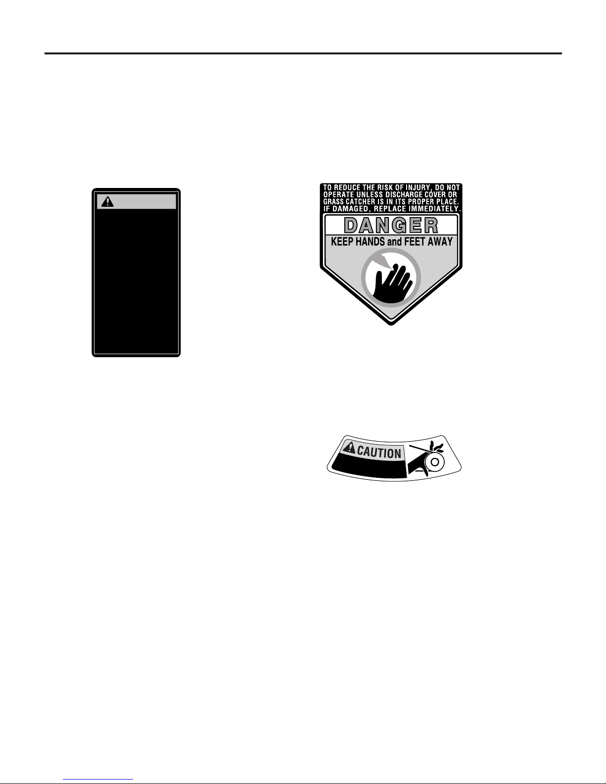
Located on the discharge outlet guard. This decal warns
not to operate the mower without the discharge outlet
guard in place and either the Grass Catcher, Mulching
Plug or Side-Discharge Chute installed. This decal also
warns that there are rotating blades. Do not open the
discharge outlet guard while the engine is running.
Located on the left side of the
mower deck. This decal cautions
to keep hands away.
Located on the belt
cover. This decal
provides a list of
warnings to help avoid
serious injury.
Section 1: Safety
5
WARNING
TO AVOID SERIOUS
INJURY, READ ALL SAFETY
PRECAUTIONS CAREFULLY.
• Read the owner/operator
manual.
• Mow across slopes, not up
and down.
• Do not mow when children
or others are near.
• Keep all safety devices in
place and in working order.
• Look down and behind
before and while moving
backwards.
• Remove objects that could
be thrown by the blade.
• Do not operate machine
without belt cover secured
in place.
1918160.A (12/99)
K
e
e
p
H
a
n
d
s
A
w
!
a
y
Page 6
INTRODUCTION
This Section covers unboxing and assembling your new mower. Please carefully
read all the instructions before you
attempt to assemble the mower. After
you finish assembling the mower, read
Section 1: Safety, Section 3: Features and
Controls, and Section 4: Operation, before
using the mower.
INSPECTION
Inspect the mower immediately after
delivery. Make sure that neither the
carton nor the contents have been
damaged.
If you find or suspect any damage,
contact the carrier (trucking company)
right away. Inform them of the specific
damage and that you wish to file a claim.
To protect your rights, be sure to put this
in writing to the carrier within 15 days
after your machine arrives. The carrier
will let you know how to proceed with
your claim.
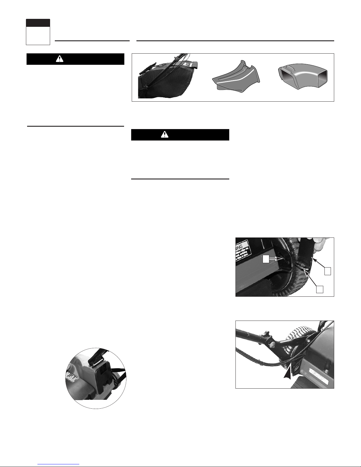
LOOSE PARTS
The following items are shipped loose
within the container.
NOTE: The mower is
shipped with the
Mulching Plug
(B, Figure 2-2)
installed in the
discharge outlet
(Figure 2-1).
• The Grass
Catcher attachment
(A, Figure 2-2).
• Side-Discharge Chute attachment
(C, Figure 2-2).
ASSEMBLING NEW UNITS
IMPORTANT: The mower is shipped
without motor oil in the engine crankcase.
Add motor oil to the engine before
starting. Follow instructions in this
Section.
Step 1: Unpack Mower
1. The mower comes fully assembled
with the handlebars folded compactly for
shipment. Remove the mower from the
shipping container.
2. The control bails (P, Figure 2-6) are
secured to the handlebar (Q) with a cable
tie. Cut the cable tie off and remove the
protective packing material.
3. Follow steps 2 through 8 to complete
mower assembly.
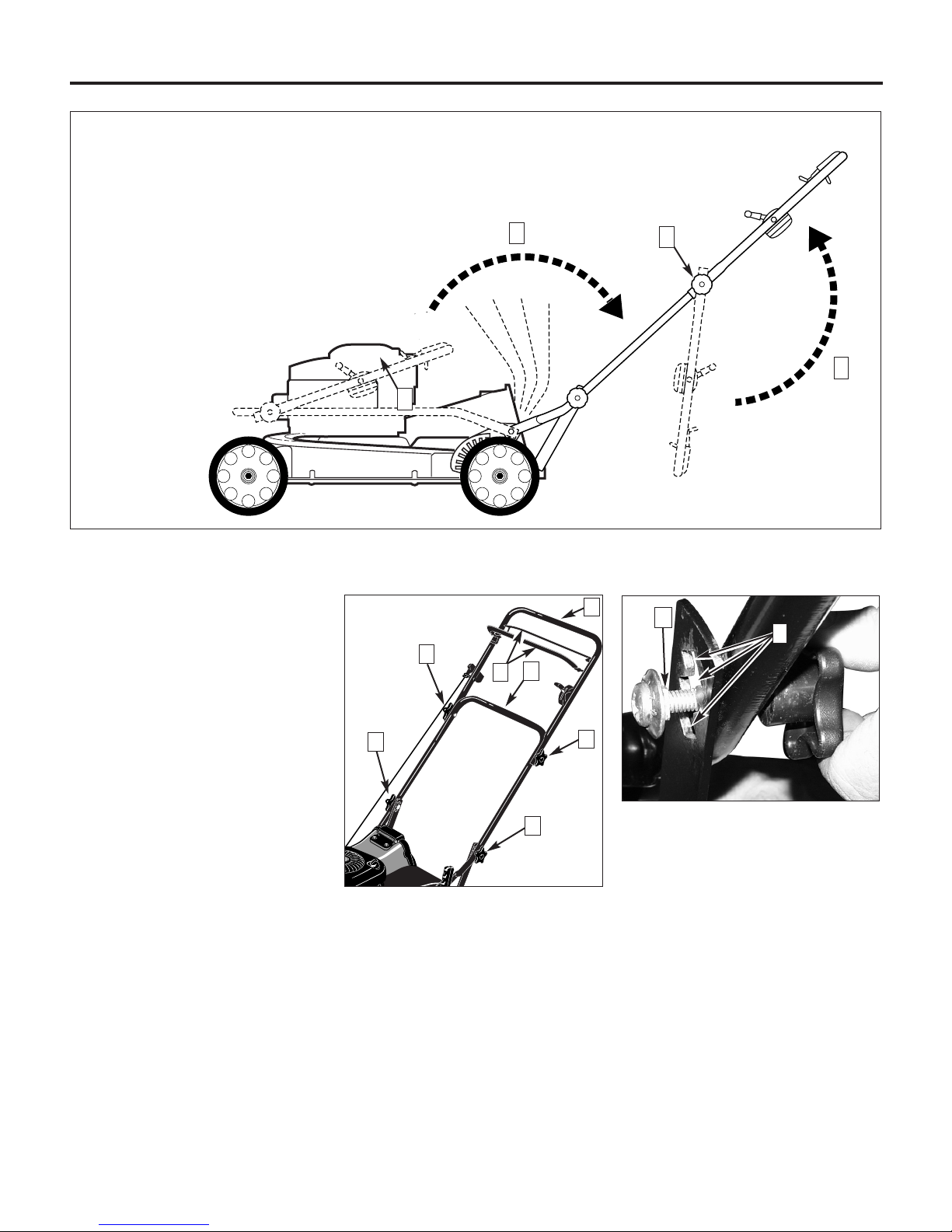
Step 2: Unfold Handlebar Assembly
1. Loosen the two lower handlebar
adjustment knobs (1, Figure 2-5).
2. Carefully unfold lower section of the
handlebar assembly (2, Figure 2-5).
Watch the cables while unfolding and
make sure that they do not pinch, kink, or
over-stretch while unfolding.
3. Tighten the two lower handlebar
adjustment knobs just enough to allow
the two handlebar struts (H, Figure 2-3)
to move in and out slightly.
4. Insert the tab (F, Figure 2-3) on each
handlebar strut into the slot (G ) one each
side of the deck. Be certain to route the
cables inside the left side strut as shown
in Figure 2-4.
5. Tighten both lower handlebar adjustment knobs securely.
6. Loosen the two upper handlebar
adjustment knobs (3, Figure 2-5).
7. Unfold the upper handlebar assembly
(4, Figure 2-5) and align with the lower
handlebar assembly. Be sure not to
pinch, kink, or over-stretch the cables
while unfolding.
8. Tighten both upper handlebar adjustment knobs securely.
9. Check the starter rope. Make sure
that it does not catch under the top
handlebar adjustment knob (I, Figure
2-6). The starter rope should stretch
unobstructed to the engine.
6
Figure 2-2: Attachments
The mower blade is sharp and can cause
serious personal injury. When working
near the mower blade, wear heavy
leather gloves to protect yourself from
the sharp edges.
Assembly
2
Section
Figure 2-3: Assembling handlebar. (Rightside handlebar strut shown.)
Figure 2-4: Cables correctly routed inside
handlebar strut.
Before operating your machine,
carefully read and understand all
safety, controls and operating instructions in this Manual, the separate
Engine Owner’s Manual, and on the
decals on the machine.
Failure to follow these instructions can
result in serious personal injury.
F
H
G
A
Figure 2-1
C
B
WARNING
CAUTION
Page 7
Section 2: Assembly
Step 3: Adjust Handlebar Height
1. Loosen one of the lower handlebar
adjustment knobs (K, Figure 2-6) and give
the knob a tap inward to free the square
shaft on the screw (N, Figure 2-7) from
the keyed slot (O) in the handlebar strut.
Repeat this step for the other side.
2. Move the handlebar strut up or down
to align the square shaft (N, Figure 2-7)
with one of the three square keyed slots
(O). The middle slot is the medium
height setting.
3. Tighten the handlebar adjustment
knobs very securely.
NOTE: Make sure that the square shaft
seats squarely into the slot before tightening the adjustment knobs.
Step 4: Add Motor Oil to Engine
1. Move the mower to a level area.
2. Add motor oil according to the specifi-
cations and instructions provided in the
separate Engine Owner's Manual.
• Keep oil level at the FULL mark on the
dipstick to avoid engine damage.
• Change oil according to schedule and
instructions in Engine Owner’s Manual.
Step 5: Perform
Final Assembly Check
1. Check all nuts, screws, and handlebar
adjustment knobs for tightness.
2. Be sure to read Section 1: Safety,
Section 3: Features and Controls and
Section 4: Operation before using the
mower.
Step 6: Set Up Mowing Mode
Your mower can be set up for any of
three mowing modes. These mowing
modes can bag clippings, mulch
clippings, or discharge clippings out the
side. See Setting Up Mowing Modes in
Section 4 for detailed descriptions and
instructions on how to set up each mode.
NOTE: The mower is shipped in Mulching
Mode. This means that the Mulching
Plug is installed into the discharge outlet
(Figure 2-1) and that the mower is ready
to mulch grass clippings.
Figure 2-6: Fully assembled handlebar
assembly.
Figure 2-7: Adjusting handlebar height.
7
N
O
Q
J
K
I
K
I
Figure 2-5: Unfolding the handlebar.
1
3
2
4
P
Page 8
INTRODUCTION
This Section introduces the features and
controls found on the lawn mower.
Carefully review the information in this
Section, then read Section 4, Operation
before using the mower.
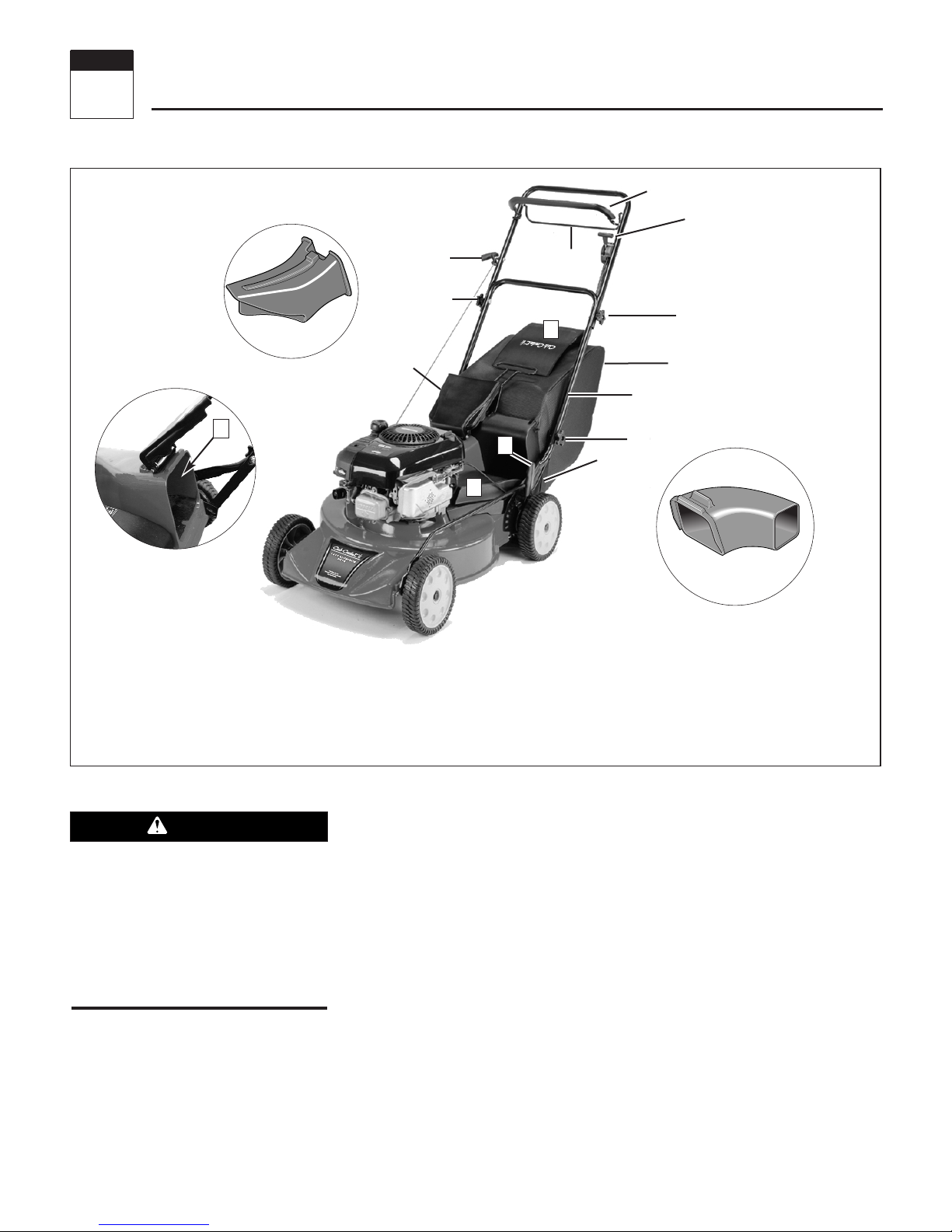
MOWER ATTACHMENTS
The mower is supplied with three easily
changed attachments —the Grass
Catcher (I, Figure 3-1), Mulching Plug (N)
and Side-Discharge Chute (M)— which
provide three different mowing modes.
See Setting Up Mowing Modes in Section
4 for detailed information on how to
install and use the attachments.
A unique feature, the Cub Cadet Rapid
Attach
TM
System, is incorporated into the
design of the attachments. This system
enables you to quickly and easily install
the attachments without using tools.
Grass Catcher Attachment
Use the Grass Catcher (G, Figure 3-1) to
collect clippings for disposal. The bag
can hold over two bushels of clippings.
The Grass Catcher is equipped with the
Cub Cadet
®
Smart BagTMfeature (F,
Figure 3-1). The Smart Bag feature is a
grass fill indicator that provides a visual
alert when the bag is full. See Bagging
Mode in Section 4 for detailed information.
Side-Discharge Chute Attachment
Use the Side-Discharge Chute (M, Figure
3-1) to direct grass clippings out the left
side (from operator’s position) of the
mower. See Side-Discharge Mode in
Section 4.
Figure 3-1
Features and Controls
3
Section
8
Before operating your machine,
carefully read and understand all
safety, controls and operating instructions in this Manual, the separate
Engine Owner’s Manual and on the
decals on the machine.
Failure to follow these instructions can
result in serious personal injury.
H
G
I
L
J
H
E
D
C
N
M
K
A
O
A: Operator Presence Control Bail G: Grass Catcher M: Side-Discharge Chute
B: Wheel Speed Control H: Discharge Outlet Guard N: Mulching Plug
C: Wheel Drive Bail I: Lower Handlebar Adjustment Knob (2) O: Discharge Outlet
D: Recoil Rope Starter J: Handlebar Height Adjuster (2) P: Clutch Cable Adjuster
E: Upper Handlebar Adjustment Knob (2) K: Cutting Height Adjustment Lever
F: Smart Bag
TM
Grass Fill Indicator L: Belt Cover
B
P
F
WARNING
Page 9

9
Section 3: Features and Controls
Mulching Plug Attachment
Use the Mulching Plug (N, Figure 3-1) to
mulch lawn clippings. See Mulching
Mode in Section 4.
MOWER CONTROLS
The following information identifies and
describes the controls for all mower
models.
Operator Presence Control Bail
The Operator Presence Control Bail
(A, Figure 3-1) must be pulled back
against the handlebar and held there
while starting the engine and operating
the unit. Releasing the bail will shut off
the engine and stop the mower blade.
The engine will not restart unless the bail
is pulled back against the handlebar.
NOTE: This control disengages an engine
brake when pulled back against the
handlebar and engages the engine brake
when released. The mower blade is
bolted directly to the engine shaft,
therefore it stops when the engine stops.
The engine will not restart unless the bail
is pulled back against the handlebar. See
Stopping the Engine and Mower Blade in
Section 4 for more information.
Wheel Drive Bail
The Wheel Drive Bail (C, Figure 3-1)
engages the powered rear wheels when it
is pulled up against the handlebar, and
disengages the wheels when released.
See Mowing and Turning the Mower in
Section 4 for more information.
To move the mower without engine
power, release the controls and push or
pull the mower.
NOTE: The pinion gears inside the rear
wheels may produce an occasional
knocking sound when pushing or pulling
the mower manually. This sound is
harmless. Do not lubricate the drive
wheels. Service the drive assembly only
as instructed in Section 5.
Wheel Speed Control
The Wheel Speed Control (B, Figure 3-1)
provides three different wheel speeds.
Selections are:
• 1 for low speed
• 2 for medium speed
• 3 for high speed
See Mowing in Section 4 for more information.
Cutting Height Adjustment Lever
This control (K, Figure 3-1) provides eight
cutting heights, enabling you to choose
the most appropriate height for the lawn
condition. Cutting heights range from
3/4-inches to 4-1/4-inches. See Prepara-
tion for Mowing in Section 4 for more
information.
NOTE: Actual cutting height will vary
according to turf conditions..
Recoil Rope Start
The recoil rope start (D, Figure 3-1) is
used to pull-start the engine. See the
Engine Owner’s Manual for starting information specific to your engine. Also see
Starting the Engine in Section 4.
Adjustable Handlebar Height
The mower provides three handlebar
height settings (J, Figure 3-1). See Step
5: Adjust Handlebar Height in Section 2.
ENGINE CONTROLS
Throttle
Models SRA 621 has an engine that is
equipped with a fixed throttle speed for
the most efficient engine performance
under varying loads.
Primer Bulb
The Primer Bulb is used to start a cold
engine. See the Engine Owner’s Manual
for information specific to your engine.
Fuel Shut-Off Valve
The Fuel Shut-Off Valve (if so equipped)
opens and closes the fuel line. See the
Engine Owner’s Manual for information
specific to your engine.
Page 10

Operation
INTRODUCTION
Read this Section thoroughly before you
start the engine. Then take the time to
familiarize yourself with the mower’s
basic operation.
Find an open, level area and practice
using the mower controls. Only after you
become familiar with the mower should
you use it in smaller areas or on uneven
terrain.
CUB CADET
®
RAPID ATTACHTMSYSTEM
The Rapid Attach System (Figure 4-1) is a
feature designed into the mower deck
which enables you to install and remove
the Grass Catcher, the Side-Discharge
Chute and the Mulching Plug quickly and
easily.
The Grass Catcher and the Side-Discharge
Chute both use the same system. This
system consists of an elongated tab (A,
Figure 4-1) on the top of the discharge
outlet and a receptacle (B) built into the
top of the Grass Catcher door and the
Side-Discharge Chute.
Attaching the Mulching Plug is just as
easy. Hold open the discharge outlet
guard (K, Figure 4-1) and insert the plug
(L), with the word “TOP” facing up, into
the discharge outlet.
SETTING UP MOWING MODES
The lawn mower has three mowing
modes: bagging mode, mulching mode
and side-discharge mode. The following
provides descriptions of the three modes
and how to implement them.
Bagging Mode
The mower is set up for bagging mode
when the Grass Catcher is attached to the
discharge outlet.
The Grass Catcher is equipped with two
handles and a swing-open door that
makes emptying easy. Use the wireformed handle to help attach, remove,
transport and empty the bag. Use the
rear cloth handle to lift the bottom of the
bag when emptying.
The Grass Catcher also has a Smart Bag
TM
grass-fill indicator (Figure 4-3) which
makes it easy to tell when the bag is full.
The indicator is a rectangular piece of
cloth sewn to the top of the bag. The
indicator lays flat against the bag when
the bag is full (F, Figure 4-3) and billows
(G) when the bag is not full.
NOTE: Windy conditions may affect the
indicator’s ability to provide an accurate
bag fill reading.
Setting Up Bagging Mode
1. With the engine and blade stopped,
remove the Mulching Plug or SideDischarge Chute.
2. Grasp the Grass Catcher by the wireformed handle. With the other hand, hold
open the discharge outlet guard (C, Figure
4-2).
3. Lower (at an angle) the bag door (D,
Figure 4-2) onto the tab (E) on the
discharge outlet. Make sure the bag door
seats squarely onto the tab and covers
the tab completely.
Removing the Grass Catcher
1. When mowing, the Grass Catcher is
full when the grass fill indicator lays flat
against the bag (F, Figure 4-3).
An alternative method for judging bag
fullness is to nudge the bag with your
foot. The bag will give easily when not
full, and will resist when full.
• Never operate the mower with the
discharge outlet guard removed or
propped open.
• Do not operate mower without the
Grass Catcher, Mulching Plug or SideDischarge Chute in place.
• Never change mowing modes or
empty the Grass Catcher while the
engine is running.
• Check the condition of the Grass
Catcher for excessive wear or deterioration. If damaged, contact an authorized dealer or the factory for a
replacement.
4
Section
Before operating the mower, carefully
read and understand all safety, control
and operating instructions in this
Manual, the separate Engine Owner’s
Manual and the decals on the machine.
Failure to follow these instructions can
result in serious personal injury.
Figure 4-2: Attaching Grass Catcher.
10
Figure 4-1: TROY-BILT®Rapid Attach
TM
System.
A
E
D
C
K
K
L
B
WARNING
WARNING
Page 11

Section 4: Operation
2. With the engine and blade stopped,
hold open the discharge outlet guard (C,
Figure 4-2). With the other hand, grasp
the wire-formed handle and guide the bag
up and off the discharge outlet.
Mulching Mode
The mulching mode cuts and recuts grass
clippings within the mower housing
before recycling the finely cut clippings
into the lawn. Mulching makes it easier
for the the lawn to absorb the grass
nutrients back into the soil.
Setting Up Mulching Mode
1. With the engine and blade stopped,
remove the Grass Catcher or the SideDischarge attachment.
2. Lift open the discharge outlet guard
(K, Figure 4-1).
3. Position the plug with the word “TOP”
facing up and push the Mulching Plug
firmly into the discharge outlet (Figure
4-4).
4. The plug’s flange (rim) must fit snugly
against the edge of the discharge outlet to
ensure efficient mulching (Figure 4-4).
Removing the Mulching Plug
1. With the engine and blade stopped, lift
open the discharge outlet guard.
2. Grasp the Mulching Plug’s hand-grip
with one hand and pull back until the plug
clears the discharge outlet.
Side-Discharge Mode
Use the Side-Discharge Chute to disperse
grass clippings onto the lawn.
Setting Up the Side-Discharge Chute
1. With the engine and blade stopped,
remove the Grass Catcher or Mulching
Plug.
2. Lift open the discharge outlet guard
(K, Figure 4-1) and lower the SideDischarge Chute opening (B, Figure 4-1)
onto the discharge outlet tab (A). Make
sure it covers the tab completely.
Removing the Side-Discharge Chute
1. With the engine and blade stopped, lift
open on the discharge outlet guard (K,
Figure 4-1).
2. With the other hand, grasp the SideDischarge Chute and guide it up and off
the discharge outlet tab.
PREPARATION FOR MOWING
Review Section 1: Safety and Section 3:
Features and Controls. Then read this
Section completely before starting the
mower.
1. Move lawn mower to a clear, level
area - If on a grassy area, make sure the
grass is low enough as to not interfere
with blade rotation when starting.
2. Inspect area to be cut - Check for and
remove debris such as rocks, toys, wire,
bones, sticks, etc., which could be picked
up and thrown by the blade. Also inspect
the terrain for holes or other obstacles.
3. Check mower -
• Check the mower for loose or missing
hardware. Tighten or replace before
starting the mower.
• Check the Operator Presence Control
Bail for freedom of movement.
• Check the Wheel Drive Control Bail for
freedom of movement.
• Check blade for excessive wear or
damage. Do not operate the mower
with a damaged blade.
• Securely connect the spark plug wire to
the spark plug.
4. Adjust handlebar height - The mower
has three handlebar heights which can be
adjusted as follows:
a. Loosen one of the lower handlebar
adjustment knobs (H, Figure 4-5) and
give the knob a tap to free the
handlebar strut (K) for adjustment.
Repeat for the other side.
b. Adjust the handlebars to the
desired height and then tighten the
handlebar adjustment knobs. Make
sure that the square shank on the
screw (J, Figure 4-5) seats squarely
into one of the square slots (I).
5. Set cutting height - You can set the
mower to any of eight cutting heights.
Cutting heights range from 3/4" to 4-1/4".
NOTE: Actual cutting height will vary
according to grass, terrain, and soil conditions.
11
Figure 4-4: Installed Mulching Plug.
Figure 4-3: Smart BagTMindicates when bag is full (F) and not full (G).
Figure 4-5: Adjusting handlebar height.
H
J
F
G
I
K
To avoid personal injury, never adjust
cutting height while engine is running.
Release all handlebar controls and wait
for all motion to stop before adjusting
cutting height.
WARNING
Page 12

Section 4: Operation
a. To adjust cutting height, pull the
Cutting Height Lever (A, Figure 4-6)
away from the mower to release the
tab from the slot. Be sure to grip the
lever firmly to prevent the mower deck
from dropping down rapidly.
b. While pulling the lever away from
the mower, move the lever towards the
back of the mower (B, Figure 4-6) for a
higher cut or towards the front of the
mower (C) for a lower cut.
c. Seat the lever’s tab squarely into
the slot.
IMPORTANT: The mower is equipped
with a safety flap located on the rear of
the mower deck. After setting the cutting
height, be certain that the flap hangs
freely and is not caught under the deck.
6. Prepare Engine -
• Check oil level - If this is a new mower,
add motor oil as described in the Engine
Owner’s Manual; otherwise, check oil
level and add as recommended in the
Engine Owner’s Manual.
• Add fuel - Fill the fuel tank with gasoline
according to the directions in the
separate Engine Owner’s Manual.
Follow all instructions and Safety rules
carefully.
• Check air filter - The engine is
equipped with an air filtration system.
When clogged, it causes starting difficulties and operates inefficiently. See
the Engine Owner’s Manual for information on how to maintain the air
filter system.
OPERATING THE MOWER
The following procedures explain how to
start, stop and operate the mower.
Starting the Engine
1. Open the fuel shut-off valve, if so
equipped.
2. Prime the engine by pushing the
primer bulb firmly 3 times.
NOTE: Priming may not be necessary
when restarting a warm engine.
However, cool weather may require
priming again. See the Engine Owner’s
Manual for priming information.
3. Stand behind the mower handlebar
and pull the Operator Presence Control
Bail (A, Figure 3-1) back against the
handlebar and hold.
4. Check behind you for obstacles, then
slowly pull the recoil rope (E, Figure 3-1)
until resistance is felt. Pull the rope out
rapidly to start engine. Let the rope
return slowly. If the engine fails to start
after three pulls, repeat steps 2-4.
Stopping the
Engine and Mower Blade
1. Release the Operator Presence Control
Bail (A, Figure 3-1) to stop the engine and
blade.
Emergency Stopping
Release all controls. This stops the
engine, wheel movement and the blade.
IMPORTANT: The mower is equipped
with a Blade Control System which is
designed to stop the mower blade within
three (3) seconds after releasing the
Operator Presence Control Bail. This
system also stops the engine.
Mowing
1. Start the engine. See Starting the
Engine in this Section.
2. Use the Wheel Speed Control to select
a wheel speed. The mower has three
wheel speeds. Select a slower speed
when first starting out (or when learning
how to use the mower), then move into
faster speeds if needed.
• Low Speed (1) - is engaged when the
lever is pulled all the way back. Low
speed provides the most efficient cut.
• Medium Speed (2) - is engaged when
the lever is moved to the middle detent
position (the control lever will click into
place). This speed is a good compromise for speed and cutting performance.
• High Speed (3) - is engaged when the
lever is pushed all the way forward.
High speed enables you to cover the
cutting area more quickly, but may
result in a less efficient cut.
To avoid personal injury, keep hands
and feet clear of mower blade or other
rotating parts.
If the Blade Control System does not
operate properly, the blade could
continue to rotate for longer than three
(3) seconds after releasing the Operator
Presence Control Bail. If this occurs,
discontinue using the mower and immediately contact your local authorized
dealer or the factory for instructions.
Do not operate the mower until the
Blade Control System is repaired.
Failure to do this could result in
personal injury or property damage.
GASOLINE IS HIGHLY FLAMMABLE AND
ITS VAPORS ARE EXPLOSIVE.
Follow the gasoline safety rules in this
Manual (Section 1) and in the separate
Engine Owner’s Manual.
Failure to follow gasoline safety instructions can result in serious personal
injury and property damage.
12
Do not operate the engine in an
enclosed area. Engine exhaust contains
carbon monoxide, a deadly gas that is
odorless, colorless and tasteless.
Always run the engine outdoors and
make sure there is adequate ventilation.
Figure 4-6: Cutting height adjustment.
C
A
B
To avoid injury or property damage,
thoroughly inspect area where mower is
to be used and remove all stones,
sticks, wires, bones, nails and other
foreign objects.
DANGER
DANGER
WARNING
WARNING
WARNING
Page 13

Section 4: Operation
This speed is most effective on short,
thin grass.
3. Pull the Wheel Drive Bail (B, Figure
4-7) up against the handlebar to power
the rear wheels and move forward.
NOTE: Release the Wheel Drive Bail and
continue to hold the Operator Presence
Control Bail (A, Figure 4-7) to pause
during mowing with the engine running,
or to maneuver in tight or difficult
conditions.
Turning the Mower
1. For short turns, release the Wheel
Drive Bail (B, Figure 4-7) but continue to
hold the Operator Presence Control Bail
(A). This disengages the wheel drive, but
the engine continues to run.
2. Press down on the handlebar to raise
the front end slightly.
3. Push the handlebar opposite the
direction to which you want to turn.
4. For longer, wider turns, there is no
need to disengage the powered wheels.
Figure 4-7 : Disengaging the wheels with
engine running.
A
B
MOWING TIPS AND HINTS
Mow When Lawn Is Dry
Do not mow grass when it is wet. Wet
grass is difficult to mow and clumps
together inside the mower housing. This
causes inefficient operation and an
uneven cut. Additionally, wet clippings
stick together in unsightly clumps on top
of the lawn which causes inefficient
absorption of nutrients back into the soil.
Avoid Midday Mowing
If possible, mow in the late afternoon or
early evening to avoid exposing newly cut
grass to the drying effects of direct
sunlight.
Never Cut Lower Than One-Third Grass
Height In One Pass
If possible, mow
often enough or
high enough to
avoid cutting off
more than 1/3 of
the grass height.
For example, if you
are maintaining your lawn at 2", mow
before it reaches 3".
Removing more than 1/3 of total grass
blade length may expose tender, shaded
stems to the drying effects of the sun and
wind and produce a dull, brown-looking
lawn. Cutting off too much leaf area is
also a shock to the root system and it
may take weeks to repair the damage.
Clean Mower Frequently
Clean the mowing housing frequently to
remove any grass build-up. Refer to the
cleaning instructions in Section 5.
Vary Cutting Pattern
Vary the cutting
pattern from week
to week. One week
mow horizontally.
Mow vertically the following week. This
helps prevent wear patterns and soil compaction.
Side-Discharge Mowing
When in Side-Discharge mode, try cutting
in a circular pattern with the chute
inward, facing the uncut area. This
results in less clumping by recutting the
clippings for a finer, cleaner appearance.
Avoid Sharp Turns
Sharp turns may produce an uneven cut.
If possible, follow natural ground
contours or use gentle, sweeping turns
for a better looking lawn.
Mow Long Grass Twice
If the grass
is 5" long or
more, cut it
once at the
highest
setting and then mow it again at the
desired height. This method may
produce too many clippings to use the
mulcher effectively. Use the Grass
Catcher to remove the grass clippings.
Use Extreme Caution on Slopes
When operating on
sloping ground,
exercise extreme
caution and use good
common sense to
avoid possible
personal injury or property damage.
Do not mow steep slopes! Avoid slopes
greater than 15 degrees, or wherever
footing is unsure. If a slope is difficult to
stand on, it is probably too steep to mow
(in such a case, it may be best to
establish a ground cover that doesn’t
require mowing).
Do not mow on slopes when the ground
is wet. Mow across the face of slopes,
never up and down. Slow down and
exercise extreme caution when changing
direction on slopes. Keep the Wheel
Drive Bail engaged to ensure easier
operation and better control of the mower
Empty Grass Catcher When Full
Emptying the Grass Catcher when it is full
results in better collection and mower
performance. Empty the bag as soon as
the bag is filled. See Bagging Mode for
more information on the Smart Bag
feature.
13
To avoid injury or property damage:
• Maximum safe operating angle is 15o.
• Exceeding maximum safe operating
angle may cause tipping or loss of
footing.
• Do not mow wet slopes.
• Mow across slopes, not up and down.
• Exercise extreme caution when
changing direction on slopes.
1
3
WARNING
Page 14

14
Section 4: Operation
Match Speed
To Terrain and Conditions
Adjust the speed to grass conditions and
terrain. Use Low and Medium speeds for
normal mowing conditions. You’ll get
better results at slower speeds, especially
if the grass is tall or lush. Use High speed
to transport the mower or when grass
conditions are light and appearance is not
as important.
Keep Mower Blade Sharp
A sharp blade cuts the grass cleanly,
resulting in a smooth, evenly cut lawn. A
dull blade tears at the grass and will fray
the tips so that they dry out quickly
resulting in a dull, brown-looking lawn.
See Blade Sharpening and Balancing in
Section 5 of this manual for more information.
Mulching Leaves
A light covering of leaves can be effectively mulched into the turf. As the leaves
decompose, they provide valuable organic
matter and minerals to the soil.
To ensure effective mulching, be sure the
leaves are dry. Use a slow travel speed
and don’t try to mulch a deep layer of
leaves.
NOTE: Oak leaves are acidic and may
affect the soil pH level when mulched. A
pH soil test should be used if oak leaves
are abundant on your property.
Page 15

ENGINE OIL SERVICE
Check the engine oil level before starting
the engine each day and after each 5
hours of continuous operation. Running
the engine when the oil level is low will
quickly ruin the engine.
Change engine oil after the first 2 hours
of break-in operation, thereafter, in accordance with your Engine Owners Manual.
Change more often in extremely dirty or
dusty conditions. Refer to the Engine
Owner’s Manual for detailed information
on changing oil.
SERVICING THE AIR CLEANER
The engine air cleaner filters dirt and dust
out of the air before it enters the carburetor. Operating the engine with a dirty,
clogged air cleaner can cause poor performance and damage to the engine.
Never operate the engine without the air
cleaner installed. Inspect and service the
air cleaner more often if operating in very
dusty or dirty conditions.
Service the air cleaner as instructed in the
separate Engine Owner’s Manual.
REMOVING AND
REPLACING THE BELT COVER
Removing the Belt Cover
1. Use a 3/8" wrench to remove both
screws (D, E, Figure 5-1).
2. Lift the back end of the cover then
carefully pull out.
Replacing the Belt Cover
1. Seat the rear end of the cover. Make
sure that both control cables are routed
through the cutout in the rear of the
cover. This will help prevent damage
caused by pinching the cables under the
cover or contact with the transmission
pulley or belt.
2. Tighten screws snugly. Do not overtighten (D, E, Figure 5-1).
TIPPING THE MOWER FOR
SERVICE
1. Before tipping the mower, make sure
that the fuel tank is empty to prevent the
possibility of gasoline spillage. See
“DANGER” statement that follows.
Maintenance
5
Section
When working near the blade, wear
heavy leather gloves to protect yourself
from the sharp edges on the blade.
15
REQUIRED MAINTENANCE SCHEDULE
•
Change more frequently in dusty or dirty conditions. Change after first 2 hours of
break-in operation.
Check after first 2 hours of break-in operation.
See Engine Owner’s Manual for service recommendations.
Before and after storing unit for 3 weeks or more.
◆
✝
▲
■
Clean engine
Check clutch spring extension
Change engine oil
Service foam pre-cleaner air filter
(if so equipped)
Service paper air filter
(if so equipped)
Clean mower housing
Clean under belt cover
Clean drive-wheel pinion gears
Service spark plug
Check nuts and screws
Inspect spark arrester (if so equipped)
Check engine oil level
•
•
▲
✝
◆▲
▲
▲
After each use
After each 50
operating hours
After each 100
operating hours
After each 5
operating hours
✝
Annually
•
•
Every 25
Hours
PROCEDURE
Every 10
Hours
As Noted
Before
Using
Before inspecting, cleaning or servicing the machine, shut off engine, wait for moving parts to stop, disconnect spark plug wire and move wire away from spark plug.
Failure to follow these instructions can result in serious personal injury or property damage.
Figure 5-1: Belt cover
E
D
Do not operate the mower without the
belt cover in place. Doing so could
result in personal injury or damage to
components.
WARNING
WARNING
WARNING
Page 16

Section 5: Maintenance
2. When servicing the underside of the
mower, the mower should be tipped only
in the direction of the muffler. Tipping
the mower away from the muffler could
result in engine damage or difficult
starting.
SPARK PLUG SERVICE
Inspect and clean or replace the spark
plug after every 100 operating hours or
annually. Set the gap as described in the
separate Engine Owner’s Manual.
In some areas, local law requires using
resistor spark plugs to suppress ignition
signals. If the engine was originally
equipped with a resistor spark plug,
replace with the same type.
CLEANING THE ENGINE
The engine must be kept clean to insure
smooth operation and to prevent damage
from overheating. Refer to the Engine
Owner’s Manual for more information.
CLEANING UNDER
THE MOWER HOUSING
Check the mower regularly for grass
build-up. Cleaning under the mower deck
should be done after (rather than before)
operating the mower, as grass is moist
and removed more easily.
1. Tip mower towards the muffler onto
its side. See Tipping the Mower for
Service in this Section.
2. Brush or scrape off grass build-up.
CLEANING THE GRASS CATCHER
Bag cleanliness affects collection performance as a dirty bag will restrict air flow.
Clean the Grass Catcher bag annually,
more often in dusty environments.
IMPORTANT: Do not wash or dry the
Grass Catcher in a washing machine or
dryer.
1. To clean the bag, remove it from the
mower and hand wash the fabric with
mild detergent.
2. Rinse the bag thoroughly with clean
water and allow to dry completely before
using. Do not use a damp bag.
CLEANING UNDER BELT COVER
Check underside of belt cover for grass
clippings every 10 hours of use.
1. Remove the belt cover. See
Removing the Belt Cover in this Section.
2. Remove any grass clippings or debris.
3. Replace belt cover. See Replacing the
Belt Cover in this Section.
SPARK ARRESTER
SCREEN SERVICE
If the engine muffler is equipped with a
spark arrester screen, remove and clean it
according to the time intervals and
instructions in the separate Engine
Owner’s Manual.
CARBURETOR/GOVERNOR
CONTROL ADJUSTMENTS
The carburetor was adjusted at the
factory for best operating speed. Refer to
the separate Engine Owner’s Manual for
any adjustment information or see your
authorized engine service dealer.
The governor controls the maximum safe
operating speed and protects the engine
and all moving parts from damage caused
by overspeeding. Do not tamper with the
engine governor settings. Seek authorized service if a problem exists.
MOWER BLADE MAINTENANCE
Blade Inspection
1. Tip mower towards the muffler onto
its side. See Tipping the Mower for
Service in this Section.
2. Inspect periodically for a dull or
slightly nicked blade. Sharpen if needed.
Also check for a deformed, cracked, or
excessively worn blade (Figure 5-2). Do
not use the mower if any of these conditions exist. Replace the blade immediately.
3. Check the blade screw for tightness.
If loose, tighten to 35 ft-lbs with a 3/4"
torque wrench.
Before inspecting, cleaning or servicing the machine, shut off engine, wait for moving parts to stop, disconnect spark plug wire and move wire away from spark plug.
Failure to follow these instructions can result in serious personal injury or property damage.
16
Figure 5-2: Mower blade inspection.
New Blade
Replace blade immediately if cracked,
deformed or badly nicked.
Damaged Blade
Before servicing the underside of the
mower:
• MOVING PARTS HAZARD!
Stop engine, wait for all parts to stop
moving, and disconnect spark plug
wire.
• FIRE - EXPLOSION HAZARD!
Gasoline is highly flammable and its
vapors are explosive.
1. Drain fuel into an approved container outdoors, away from open
flame.
2. Be sure engine and muffler are
cool before draining gasoline.
3. Do not smoke.
Failure to comply with the above can
result in serious personal injury and
property damage.
Never reach under mower deck while
the engine is running. Mower blade
rotates at all times while engine is
running and up to 3 seconds after it is
shut off.
WARNING
DANGER
WARNING
Replace if separation
begins to form.
Page 17

Section 5: Maintenance
Removing Mower Blade
IMPORTANT: The blade coupler
(D, Figure 5-5) may come off the engine
shaft when removing the blade. If it does,
do not lose the square key (C). The key
fits into a square slot inside the blade
coupler. Without it, the blade will not
rotate.
1. Remove the spark plug wire from the
spark plug and move it away.
2. Tip mower towards the muffler onto
its side. See Tipping the Mower for
Service in this Section.
3. Use a 3/4" wrench to loosen the blade
screw (A, Figure 5-5). Hold the blade
with a gloved hand to prevent the blade
from rotating.
4. Remove blade screw and Belleville
washer (A, B, Figure 5-5) .
5. Remove blade. You may have to give
the blade a tap to jar it loose from the
mounting tabs.
Installing Mower Blade
1. Remove the spark plug wire from the
spark plug and move it away.
2. Tip mower towards the muffler onto
its side. See Tipping the Mower for
Service in this Section.
3. If the blade coupler (D, Figure 5-5)
and/or square key (C) came off the engine
shaft during blade removal, reinstall those
parts back onto the engine shaft.
4. Position the blade with the curved
ends facing downward (Figure 5-4).
5. Slip the Belleville washer (B, Figure
5-5) onto the screw (A). Face the dishedin side to the blade.
6. Mount the blade onto the two tabs of
the blade coupler. Make sure that you
seat the blade completely onto the
coupler.
7. Insert the screw and washer through
the blade and into the blade coupler.
Tighten with a torque wrench to 35 ft-lbs.
Sharpening and
Balancing Mower Blade
IMPORTANT: We recommend that the
blade be sharpened by a professional
sharpening service. Replace a cracked or
severely worn blade with a new one.
1. Remove blade from the mower. See
Removing Mower Blade.
2. Clamp the blade in a vise. Use a metal
file or grinder to sharpen the blade while
maintaining the original cutting angle. It
is very important to maintain the original
cutting bevel to insure the most effective
cut.
3. To retain blade balance, remove the
same amount of material from both ends
of the blade.
4. To check blade balance, place the
blade on a rounded pivot such as a pencil
or pen under the center hole. Hold blade
parallel to ground then release. See
Figure 5-6. If blade is unbalanced, the
heavier side will lean downward.
5. Use a file to lightly remove material
from the heavier side of the blade.
6. See Installing Mower Blade for infor-
mation on how to re-install the blade.
REMOVING AND
REPLACING DRIVE BELT
This procedure can be made easier by
removing the blade (see Removing
Mower Blade); however, blade removal is
not absolutely necessary.
Mower blade is sharp.
• Wear heavy leather gloves when
working near or with blade for protection from sharp edges.
• Wear safety approved eye protection
when sharpening blade to protect eyes
from flying metal debris.
Figure 5-5: Mower blade assembly.
Figure 5-3: Removing or installing blade.
Figure 5-6: Balance blade on pivot to check blade balance.
Figure 5-4: Correct blade installation.
17
Before inspecting, cleaning or servicing the machine, shut off engine, wait for moving parts to stop, disconnect spark plug wire and move wire away from spark plug.
Failure to follow these instructions can result in serious personal injury or property damage.
B
C
D
E
A
WARNING
WARNING
Curved end down
Mower Deck
Curved end down
Lawn
Page 18

Section 5: Maintenance
1. Remove the belt cover. See
Removing the Belt Cover in this Section.
2. Press firmly downward on the cable
mounting bracket (A, Figure 5-7) until it
tilts and the belt slackens.
3. Remove belt (B, Figure 5-7) from
transaxle pulley.
4. Tip the mower onto its side (towards
the muffler) and pull the belt through the
cutout in the housing.
5. Do this step only if you did not
remove the mower blade — otherwise, go
onto step 6.
a. Make sure the spark plug wire is
removed from the spark plug and
moved away from the plug. Rotate the
blade so that one end is somewhere
within the front of the mower housing.
b. Work the belt around and over that
end of the blade (Figure 5-8).
c. Rotate the blade so that the other
end is somewhere within the front of
the mower housing and work the belt
around and off the mower.
d. Work the new belt around and over
the same end of the blade.
e. Rotate the blade so that the other
end of the blade is somewhere within
the front area of the mower housing
and work the new belt around and over
the same end.
6. Seat the new belt into the groove on
the engine pulley that is located on the
blade drive shaft.
7. Grasp one end of the new belt and
insert it in and through the cutout in the
housing.
8. Tip the mower back down to its
normal position.
9. Apply firm pressure against the cable
mounting bracket on the transaxle
assembly (A, Figure 5-7) until it tilts
forward.
10. Pull the belt over the transaxle pulley
and into the groove.
11. Release pressure on the transaxle
bracket slowly. Make sure that the belt
seats properly into the pulley groove.
12. Check the other end of the belt
(engine pulley) to insure that it is seated
properly into the groove.
13. Reinstall the belt cover. See
Replacing the Belt Cover in this Section.
ADJUSTING
WHEEL DRIVE CONTROL
Loss of wheel drive indicates that the
Wheel Drive Control may need adjustment. This condition could also be the
result of not completely engaging a wheel
speed gear setting. Before you adjust the
wheel drive control cable, move the Wheel
Speed Control Lever to 1 (all the way
back) or to 3 (all the way forward). If the
wheels still do not engage, adjust the
wheel drive clutch spring.
1. Remove the belt cover (See Removing
and Replacing the Belt cover) and locate
the wheel drive clutch spring.
2. Measure the length of the body of the
wheel drive clutch spring (Figure 5-9).
3. Engage the Wheel Drive Control Bail
and measure the extended length of the
spring body again (Figure 5-10).
4. The difference between the two measurements should be approximately 1/4".
Adjust if the result does not meet this
specification. Spring extension is
adjusted with a cable adjuster (R, Figure
3-1) on the wheel drive cable. To adjust,
hold the turnbuckle (A, Figure 5-11) while
turning each adjuster (B, Figure 5-11)
away from the turnbuckle 1/2 turn each.
Figure 5-7: Press down on point “A” to
remove or install belt.
Figure 5-8: Remove or install belt around
blade.
A
B
Figure 5-9: First measurement with drive
clutch spring disengaged.
About 1"
Before inspecting, cleaning or servicing the machine, shut off engine, wait for moving parts to stop, disconnect spark plug wire and move wire away from spark plug.
Failure to follow these instructions can result in serious personal injury or property damage.
Figure 5-10: Second measurement with
drive clutch spring engaged.
About 1-1/4"
Figure 5-11: Drive cable adjustment.
B
A
B
18
WARNING
Page 19

Section 5: Maintenance
5. Measure again, as in steps 2, 3 and 4
to determine if you need to continue
adjusting. Adjust until the two spring
measurements differ in length by approximately 1/4".
6. Reinstall the belt cover. See
Replacing the Belt Cover.
GRASS CATCHER
PARTS REPLACEMENT
The Grass Catcher is made up of three
parts: the door, the frame, and the cloth
bag. The following procedure explains
how to remove and replace each of the
parts.
Replacing the Grass Catcher Door
1. Remove the Grass Catcher from the
mower.
2. The door is mounted onto rods at both
ends of the wire-formed handle. Squeeze
the handle with one hand while pulling the
top-side of the door (C, Figure 5-12) out
and off the end of the rod (D).
3. To replace the door, insert one of the
ends of the wire-formed handle (D, Figure
5-12) into the hole in the top-side of the
door (C).
4. Squeeze the handle with one hand
while you pull the other side of the door
(C, Figure 5-12) up and over the end of
the other rod (D). The door should swing
freely when done.
Replacing the Cloth Bag or Frame
1. Remove the Grass Catcher from the
mower.
2. Remove the Grass Catcher door. See
Replacing the Grass Catcher Door.
3. The bag is mounted over the wire
frame and under the door, and is held in
place with four plastic clips (E, Figure
5-13). Remove each of the clips by
pulling from an end and off the frame (F).
4. Pull the bag off the frame.
5. To replace the frame or bag, position
the top of the bag (long side) up.
Position the top of the frame (wireformed handle side) up. Pull the open
end of the bag over the rear end of the
frame and under the handle.
6. Press each of the bag’s four plastic
clips (E, Figure 5-13) onto the frame
opening (F).
7. Install the door. See step 3,
Replacing the Grass Catcher Door.
EXTENDED STORAGE
Use the following suggestions when
storing the mower for extended periods of
time.
• Store mower in a level position.
• Thoroughly inspect the
mower for any loose,
broken, or missing parts.
Repair or replace as
necessary.
• Remove all fuel from fuel
tank or use a fuel stabilizer
additive as directed in
Engine Owner’s Manual.
• Perform engine maintenance as
described in the Storage instructions of
the Engine Owner’s Manual.
• Check all nuts and screws for tightness.
• On electric start models remove key
from keyswitch.
• Charge the battery for 24 to 48 hours
before and after seasonal storage.
• Disconnect spark plug wire from spark
plug.
Folding the Handlebar Assembly
IMPORTANT: To avoid damage to the
cables and wiring, always fold the top
section of the handlebar assembly
backward. Cables can be severely bent if
folded incorrectly.
1. Loosen the top two handlebar adjust-
ment knobs (1, Figure 5-16) while supporting the assembly with one hand.
Figure 5-12: Replacing bag door.
Figure 5-13
C
D
• Never store mower with fuel in fuel
tank inside a building where fumes can
reach an open flame or spark, or where
ignition sources are present such as hot
water and space heaters, furnaces,
clothes dryers, stoves, electric motors,
etc. Make sure engine is cool before
storing.
• Drain gasoline outdoors into an
approved container.
• Do not smoke and keep away from
open flame.
Failure to follow these instructions will
result in serious personal injury or
property damage.
19
E
F
Before inspecting, cleaning or servicing the machine, shut off engine, wait for moving parts to stop, disconnect spark plug wire and move wire away from spark plug.
Failure to follow these instructions can result in serious personal injury or property damage.
Figure 5-16: Folding the mower for storage.
3
1
4
2
WARNING
DANGER
Page 20

Section 5: Maintenance
2. Fold the top section of the assembly
backward (2, Figure 5-16). Guide the
cables carefully while folding. Be sure
not to bend, pinch, or stretch the cables.
IMPORTANT: To avoid damage to cables,
always fold the top section of the
handlebar assembly backward and the
bottom section forward.
3. Still supporting the handlebar
assembly with one hand, loosen the two
lower handlebar adjustment knobs
(3, Figure 5-16) just enough to dislodge
both handlebar struts (L, Figure 5-17)
from the slots (K) in the wheel bracket
assembly.
NOTE: The handlebar height could inadvertently change if the lower adjustment
knobs are loosened excessively during
this step.
4. Carefully fold the bottom section of
the handlebar assembly forward over the
engine (4, Figure 5-16). Guide the cables
carefully while folding. Be sure not to
bend, pinch, or stretch the cables; also,
keep cables away from muffler — the
outer cable covering can be burned if the
engine is still hot.
5. To unfold handlebar assembly,
perform folding steps in reverse order.
PINION GEAR SERVICE
The mower drive wheels (rear wheels)
each contain a pinion gear. This gear
transfers drive power to the wheels which
propels the mower forward. It is very
important to keep these internal parts
clean. The following procedure explains
how to disassemble, clean and reassemble the mower drive wheels. Conduct this
maintenance on the pinion gears after
every 50 operating hours.
Tools and Materials
• 9/16" Socket and Ratchet
• Small Snap-Ring Pliers
• Cleaning Rags
Procedure
NOTE: This procedure is done only on
the drive wheels (rear wheels).
1. Place a sturdy, stable block under the
mower to elevate a rear wheel off the
ground.
2. Use a 9/16" wrench to remove wheel
assembly (A, B, C, D, E, Figure 5-18).
3. Remove snap-ring (J, Figure 5-18)
from axle.
4. Remove shim(s) (I, Figure 5-18). The
number of shims vary from mower to
mower. Put them next to the snap-ring.
5. Pull off pinion gear (H, Figure 5-18).
6. Remove drive pin (G, Figure 5-18).
7. Remove plastic washer/seal
(F, Figure 5-18).
8. Thoroughly clean off debris from the
drive pin, axle, hole in axle (for drive pin)
and the washer/seal.
9. Reinstall washer/seal (F, Figure 5-18).
Be sure to install flat side of washer
against bearing (mower deck).
10. Insert the drive pin (G, Figures 5-18)
into the hole in the axle.
NOTE: The pin should slide freely within
the hole.
11. Thoroughly clean pinion gear,
including surface area and cavity.
12. Slide the pinion gear (H, Figure 5-18)
onto the axle with the cavity toward the
mower. Press the gear firmly against the
washer/seal (F, Figure 5-18). Be certain
that the gear is flush against the surface
of the washer/seal and that the
washer/seal is flush against the wheel
mounting bracket.
13. Slide the shims (I, Figure 5-18) onto
the axle and against the pinion gear. Be
sure to install the same number of shims
as were removed from the unit.
14. Install the snap-ring onto the axle
(J, Figures 5-18) and into the groove in
the axle. Pull the pinion gear outward to
be sure that the snap-ring seats properly.
NOTE: If you can’t get the snap-ring into
the slot in the axle, press the pinion gear
more firmly against the washer/seal. Do
not leave off shims.
15. Insert wheel screw (A, Figure
5-18) through wheel (B), flat washer (C),
center hole in wheel shield (D), and
spacer (E). The wheel shield has a double
edge on the rim. Position this side
toward the wheel.
16. Align pinion gear with the hole in the
wheel shield. At the same time, align the
wheel screw with the welded nut on the
wheel bracket and tighten securely.
Figure 5-17: Dislodging handlebar struts.
K
L
20
Before inspecting, cleaning or servicing the machine, shut off engine, wait for moving parts to stop, disconnect spark plug wire and move wire away from spark plug.
Failure to follow these instructions can result in serious personal injury or property damage.
Figure 5-18: Drive wheel assembly.
I
H
J
G
F
C
D
B
A
E
WARNING
Page 21

Parts List Model SRA 621
21
16
2
1
4
5
4
5
4
5
6
10
10
13
9
9
3
3
7
7
10
6
11
20
19
21
18
22
17
15
13
14
12
4
5
10
8
1 1917021 Lower Handlebar .................................... 1
2 1917026 Upper Handlebar .................................... 1
3 1917036 Handlebar Support Strut ........................ 2
4 1763767 Handlebar Adjustment Knob................... 4
5 1177038 Ext. Tooth Lock Washer, 5/16 ................ 4
6 1731025 Curved Head Screw, 5/16-18 x 1-3/4 ..... 2
7 1917087 Carriage Bolt, 5/16-18 x 1-3/4, Special... 2
8 1110108 Hex Lock Nut, 3/8-16 ............................. 2
9 1100068 Hex Hd. Screw, 3/8-16 x 3/4, GR. 5 ....... 2
10 1763682 Cable Tie................................................. 2
11 1917050 Bail Grip ................................................. 1
12 1917053 Operator Presence Control Bail .............. 1
13 1917085 Wheel Drive Bail ..................................... 1
14 1917081 Operator Presence Control Cable ........... 1
15 1918161 Decal - Bail Operating Instructions......... 1
16 710-1205 Rope Guide............................................. 1
17 720-0279 Wing Knob, 1/4-20 ................................ 1
18 1917037 Speed Control Lever/Cable ..................... 1
19 1917032 Drive Control Cable ................................ 1
10 1908677 Bushing, Nyliner..................................... 4
21 1917091 Hex Hd. Screw, M6................................. 1
22 1917092 Hex Nut, M6 ........................................... 1
Ref. # Part # Description Qty.
Ref. # Part # Description Qty.
Page 22

Parts List Model SRA 621
22
1
14
15
9
13
11
2
32
26
9
6
23
22
24
25
21
60
61
61
29
28
27
64
64
9
9
10
44
48
45
46
36
33
43
48
47
65
52
51
50
49
34
42
58
59
57
55
54
53
59
63
56
55
62
35
36
41
39
17
20
31
19
16
9
9
30
18
38
12
40
37
56
7
4
3
8
5
Page 23

Model SRA 621 Parts List
23
1 1917000 Mower Deck ........................................... 1
2 * Engine .................................................... 1
3 1917072 Support Bracket ..................................... 1
4 1917045 Torsion Spring ....................................... 1
5 1917044 Discharge Outlet Cover........................... 1
6 777S30145 Decal - Warning...................................... 1
7 1917086 Pin.......................................................... 1
8 1727342 Flange Push Nut, 5/16 dia ...................... 1
9 1754128 Hex Hd. Flange Screw, 1/4-20 x 3/4,
Self-Thrd. ............................................. 10
10 1918076 Hex Hd. Screw, 3/8-16 x 1-1/4,
Self-Thrd. ............................................. 3
11 777D06222 Decal - Logo........................................... 1
12 1918339 Spacer Tube, Plastic............................... 1
13 777S32021 Decal - Warning, Belt Cover ................... 1
14 1918223 Belt Cover............................................... 1
15 1917088 Hex Hd. Flange Screw, 1/4-20 x 2-1/4,
Self-Thrd. ............................................. 1
16 1917002 Discharge Outlet Baffle........................... 1
17 1917071 Safety Flap.............................................. 1
18 1917073 Flap Rod................................................. 1
19 777S32022 Decal - Danger, BBC Opening................. 1
20 1918284 Rubber Extrusion ................................... 1
21 1917029 Grass Catcher Door................................ 1
22 1917030 Grass Catcher Frame.............................. 1
23 1918182 Grass Catcher Bag.................................. 1
24 1917084 Mulching Plug ........................................ 1
25 1917056 Side-Discharge Deflector........................ 1
26 1917054 Mower Blade .......................................... 1
27 1917017 Engine Pulley/Blade Coupler Assy. ......... 1
28 GW-9928 Belleville Washer, 1/2" ............................ 1
29 1917060 Shoulder Screw, 3/8-24 x 1.65............... 1
30 1917005 V-Belt ..................................................... 1
31 GW-9302 Square Key, .188 x 1-1/4........................ 1
32 1746425 Rope Stop .............................................. 1
33 1917004 Transaxle................................................ 1
34 1917038 Handle Support Bracket, Left-Hand........ 1
35 1917018 Handle Support Bracket, Right-Hand...... 1
36 1723037 Hex Hd. Flange Screw, 3/8-16 x 3/4,
Self-Thrd. ............................................. 4
37 1917014 Rear Axle Bearing................................... 2
38 1917079 Washer/Seal, Nylon................................ 2
39 1918323 Pinion Gear, Right-Hand......................... 1
40 1909380 Shim, .016"............................................. A/R
1909382 Shim, .062"............................................. A/R
41 GW-9516 Snap-Ring .............................................. 2
42 1918322 Pinion Gear, Left-Hand........................... 1
43 777I22012 Decal - Blade Cutting Height................... 1
44 1909044 Round Pin .............................................. 2
45 1917003 Transaxle Pulley ..................................... 1
46 1186309 Hex Hd. Screw, 1/4-20 x 5/8, GR. 5 ....... 1
47 1917009 Cable Mounting Bracket ......................... 1
48 GW-9552 Hex Flange Hd. Screw, 1/4-20 x 1/2,
Self-Thrd. ............................................. 2
49 1917032 Drive Control Cable ................................ 1
50 1917037 Speed Control Cable/Lever ..................... 1
51 1715127 Cable Clamp ........................................... 1
52 1767754 Hex Washer Hd. Flange Screw,
#10-24 x 1/2......................................... 1
53 720-0313 Lever Grip............................................... 1
54 1917011 Rear Axle Assembly................................ 1
55 1917074 Spacer.................................................... 4
56 1909311 Flat Washer, .406" ID.............................. 4
57 1917083 Wheel Shield .......................................... 2
58 1765750 Rear Wheel/Tire Assembly ..................... 2
59 1903416 Shoulder Screw, 3/8-16 x 2.42............... 4
60 1917012 Deck Height Adjust Linkage.................... 1
61 1185257 E-Clip ..................................................... 2
62 1917010 Front Axle Assembly............................... 1
63 1765740 Front Wheel/Tire Assembly .................... 2
64 1917015 Front Axle Bearing.................................. 2
65 1917068 Compression Spring............................... 1
Ref. # Part # Description Qty.
Ref. # Part # Description Qty.
* Order parts from your local authorized engine dealer. Refer to engine/model type nameplate on engine.
A/R As Required.
Page 24

MANUFACTURER’S LIMITED WARRANTY FOR:
The limited warranty set forth below is given by Cub Cadet LLC
with respect to new merchandise purchased and used in the
United States, its possessions and territories.
Cub Cadet LLC warrants this product against defects for a
period of two (2) years commencing on the date of original
purchase and will, at its option, repair or replace, free of charge,
any part found to be defective in materials or workmanship. This
limited warranty shall only apply if this product has been
operated and maintained in accordance with the Operator’s
Manual furnished with the product, and has not been subject to
misuse, abuse, commercial use, neglect, accident, improper
maintenance, alteration, vandalism, theft, fire, water, or damage
because of other peril or natural disaster. Damage resulting
from the installation or use of any accessory or attachment not
approved by Cub Cadet LLC for use with the product(s) covered
by this manual will void your warranty as to any resulting
damage.
Normal wear parts or components thereof are subject to
separate terms as follows: All normal wear parts or component
failures will be covered on the product for a period of 90 days
regardless of cause. After 90 days, but within the two year
period, normal wear part failures will be covered ONLY IF
caused by defects in materials or workmanship of OTHER
component parts. Normal wear parts and components include,
but are not limited to: batteries, belts, blades, blade adapters,
grass bags, rider deck wheels, seats, snow thrower skid shoes,
shave plates, auger spiral rubber, tires.
HOW TO OBTAIN SERVICE: Warranty service is available,
WITH PROOF OF PURCHASE, through your local authorized
service dealer. To locate the dealer in your area, check your
Yellow Pages, or contact Cub Cadet LLC at P.O. Box 361131,
Cleveland, Ohio 44136-0019, 1-877-282-8684, or log on to our
Web site at www.cubcadet.com.
This limited warranty does not provide coverage in the following
cases:
a. The engine or component parts thereof. These items
carry a separate manufacturer’s warranty. Refer to the
applicable manufacturer’s warranty for terms and cond
tions.
b. Log splitter pumps, valves, and cylinders have a separate
one year warranty.
c. Routine maintenance items such as lubricants, filters,
blade sharpening, tune-ups, brake adjustments, clutch
adjustments, deck adjustments, and normal deterioration of
the exterior finish due to use or exposure.
d. Cub Cadet LLC does not extend any warranty for products
sold or exported outside of the United States, its possessions and territories, except those sold through Cub
Cadet LLC’s authorized channels of export distribution.
e. Parts that are not genuine Cub Cadet parts are not covered
by this warranty.
f. Service completed by someone other than an authorized
service dealer is not covered by this warranty.
g. Transportation charges and service calls are not covered.
No implied warranty, including any implied warranty of merchantability of fitness for a particular purpose, applies after
the applicable period of express written warranty above as
to the parts as identified. No other express warranty,
whether written or oral, except as mentioned above, given
by any person or entity, including a dealer or retailer, with
respect to any product, shall bind Cub Cadet LLC. During
the period of the warranty, the exclusive remedy is repair or
replacement of the product as set forth above.
The provisions as set forth in this warranty provide the sole
and exclusive remedy arising from the sale. Cub Cadet LLC
shall not be liable for incidental or consequential loss or
damage including, without limitation, expenses incurred for
substitute or replacement lawn care services or for rental
expenses to temporarily replace a warranted product.
Some states do not allow the exclusion or limitation of incidental
or consequential damages, or limitations on how long an implied
warranty lasts, so the above exclusions or limitations may not
apply to you.
In no event shall recovery of any kind be greater than the
amount of the purchase price of the product sold.
Alteration of
the safety features of the product shall void this warranty.
You assume the risk and liability for loss, damage, or injury to
you and your property and/or to others and their property arising
out of the misuse or inability to use the product.
This limited warranty shall not extend to anyone other than the
original purchaser or to the person for whom it was purchased
as a gift.
HOW STATE LAW RELATES TO THIS WARRANTY: This
limited warranty gives you specific legal rights, and you
may also have other rights which vary from state to state.
CCUUBB CCAADDEETT LLLLCC,, PP..OO.. BBOOXX 336611113311,, CCLLEEVVEELLAANNDD,, OOHHIIOO 4444113366--00001199;; PPhhoonnee 11--887777--882288--88668844
 Loading...