

Page 1

3URIHVVLRQDO6KRS0DQXDO
3URIHVVLRQDO6KRS0DQXDO
LTX Series Riding Tractors
NOTE: These materials are for use by trained technicians who are experienced in the service and repair of outd oor power
equipment of the kind described in this publication, and are no t intended for use by untrained or inexperienced individu als.
These materials are intended to provide supplemental information to assist the trained technician. Untrained or inexperienced individuals should seek the assistance of an experienced and trained professional. Read, understand, and follow all
instructions and use common sense when working on power equipment. This includes the contents of the product’s Operators Manual, supplied with the equipment. No liability can be accepted for any inaccuracies or omission in this publication,
although care has been taken to make it as complete and accurate as possible at the time of publication. However, due to
the variety of outdoor power equipment and continuing product changes that occur over time, updates will be made to these
instructions from time to time. Therefore, it may be necessary to obtain the latest materials before servicing or repairing a
product. The company reserves the right to make changes at any time to this publication without prior notice and without
incurring an obligation to make such changes to previously published versions. Instructions, photographs and illustrations
used in this publication are for reference use only and may not depict actual model and component parts.
© Copyright 2012 MTD Products Inc. All Rights Reserved
Page 2

Page 3

Table of Contents
Chapter 1: Introduction
Professional Shop Manual intent . . . . . . . . . . . . . . . . . . . . . . . . . . . . . . . . . . 1
Fasteners. . . . . . . . . . . . . . . . . . . . . . . . . . . . . . . . . . . . . . . . . . . . . . . . . . . . . 1
Assembly . . . . . . . . . . . . . . . . . . . . . . . . . . . . . . . . . . . . . . . . . . . . . . . . . . . . 3
Description of the 900 series . . . . . . . . . . . . . . . . . . . . . . . . . . . . . . . . . . . . . 3
Model and Serial Numbers . . . . . . . . . . . . . . . . . . . . . . . . . . . . . . . . . . . . . . . 4
Chapter 2: Engine related parts
Muffler . . . . . . . . . . . . . . . . . . . . . . . . . . . . . . . . . . . . . . . . . . . . . . . . . . . . . . . 5
Fuel tank removal/replacement . . . . . . . . . . . . . . . . . . . . . . . . . . . . . . . . . . . 8
Fuel Line . . . . . . . . . . . . . . . . . . . . . . . . . . . . . . . . . . . . . . . . . . . . . . . . . . . . . 9
Evaporative (EVAP) emissions system . . . . . . . . . . . . . . . . . . . . . . . . . . . . 10
Roll over valve vent . . . . . . . . . . . . . . . . . . . . . . . . . . . . . . . . . . . . . . . . . . . 12
Chapter 3: Steering
Steering alignment . . . . . . . . . . . . . . . . . . . . . . . . . . . . . . . . . . . . . . . . . . . . 15
Axles . . . . . . . . . . . . . . . . . . . . . . . . . . . . . . . . . . . . . . . . . . . . . . . . . . . . . . . 17
Sector gear and steering pinion gear . . . . . . . . . . . . . . . . . . . . . . . . . . . . . . 19
Steering shaft and hex bushing . . . . . . . . . . . . . . . . . . . . . . . . . . . . . . . . . . 21
Pivot bar . . . . . . . . . . . . . . . . . . . . . . . . . . . . . . . . . . . . . . . . . . . . . . . . . . . . 23
Chapter 6B: Electronic Power Steering
Rubber Torsion Coupling . . . . . . . . . . . . . . . . . . . . . . . . . . . . . . . . . . . . . . . 25
EPS Module . . . . . . . . . . . . . . . . . . . . . . . . . . . . . . . . . . . . . . . . . . . . . . . . . 25
EPS motor & gearbox . . . . . . . . . . . . . . . . . . . . . . . . . . . . . . . . . . . . . . . . . . 26
Troubleshooting the EPS (without the 725-05419 EPS tester) . . . . . . . . . . 27
EPS removal/replacement . . . . . . . . . . . . . . . . . . . . . . . . . . . . . . . . . . . . . . 33
Chapter 4: Body panels
What is covered by this chapter . . . . . . . . . . . . . . . . . . . . . . . . . . . . . . . . . . 35
Hood . . . . . . . . . . . . . . . . . . . . . . . . . . . . . . . . . . . . . . . . . . . . . . . . . . . . . . . 36
Hood components: Headlight removal . . . . . . . . . . . . . . . . . . . . . . . . . . . . . 37
Hood components: side vent removal . . . . . . . . . . . . . . . . . . . . . . . . . . . . . 38
Hood components: grill removal . . . . . . . . . . . . . . . . . . . . . . . . . . . . . . . . . . 39
Hood components: pivot bracket removal . . . . . . . . . . . . . . . . . . . . . . . . . . 40
Seat and Fenders . . . . . . . . . . . . . . . . . . . . . . . . . . . . . . . . . . . . . . . . . . . . . 41
Dash Panel . . . . . . . . . . . . . . . . . . . . . . . . . . . . . . . . . . . . . . . . . . . . . . . . . . 50
I
Page 4

Chapter 5: Hydro. Drive and brake system
About this chapter . . . . . . . . . . . . . . . . . . . . . . . . . . . . . . . . . . . . . . . . . . . . . 55
Externally repairable drive system problems . . . . . . . . . . . . . . . . . . . . . . . . 56
Indications that a transaxle is not warrantable . . . . . . . . . . . . . . . . . . . . . . . 61
Brake adjustment . . . . . . . . . . . . . . . . . . . . . . . . . . . . . . . . . . . . . . . . . . . . . 62
Neutral control adjustment . . . . . . . . . . . . . . . . . . . . . . . . . . . . . . . . . . . . . . 64
Linkage: pedal shaft . . . . . . . . . . . . . . . . . . . . . . . . . . . . . . . . . . . . . . . . . . . 66
Pedal shaft assembly removal . . . . . . . . . . . . . . . . . . . . . . . . . . . . . . . . . . . 67
Belt control; tensioner and idler pulleys . . . . . . . . . . . . . . . . . . . . . . . . . . . . 72
Drive belt replacement . . . . . . . . . . . . . . . . . . . . . . . . . . . . . . . . . . . . . . . . . 75
Changing transaxle hydraulic fluid . . . . . . . . . . . . . . . . . . . . . . . . . . . . . . . . 81
Brakes . . . . . . . . . . . . . . . . . . . . . . . . . . . . . . . . . . . . . . . . . . . . . . . . . . . . . 83
Transaxle removal and replacement . . . . . . . . . . . . . . . . . . . . . . . . . . . . . . 85
Chapter 6: CVT Drive and brake system
About this chapter . . . . . . . . . . . . . . . . . . . . . . . . . . . . . . . . . . . . . . . . . . . . . 93
About the variable speed drive system. . . . . . . . . . . . . . . . . . . . . . . . . . . . . 93
Externally repairable drive system problems: . . . . . . . . . . . . . . . . . . . . . . . . 94
Indications that a transaxle is not warrantable . . . . . . . . . . . . . . . . . . . . . . . 97
Brake adjustment . . . . . . . . . . . . . . . . . . . . . . . . . . . . . . . . . . . . . . . . . . . . . 97
Gear selector . . . . . . . . . . . . . . . . . . . . . . . . . . . . . . . . . . . . . . . . . . . . . . . . 99
Tensioner pulley control rod . . . . . . . . . . . . . . . . . . . . . . . . . . . . . . . . . . . . 100
Linkage: pedal shaft . . . . . . . . . . . . . . . . . . . . . . . . . . . . . . . . . . . . . . . . . . 102
Pedal shaft assembly removal: . . . . . . . . . . . . . . . . . . . . . . . . . . . . . . . . . . 102
Linkage: pedal tie strap . . . . . . . . . . . . . . . . . . . . . . . . . . . . . . . . . . . . . . . 107
Belt control: tension make-up pulley . . . . . . . . . . . . . . . . . . . . . . . . . . . . . . 109
Belt control: variable speed pulley . . . . . . . . . . . . . . . . . . . . . . . . . . . . . . . 111
Belt control: tensioner pulleys . . . . . . . . . . . . . . . . . . . . . . . . . . . . . . . . . . . 114
Drive belt replacement . . . . . . . . . . . . . . . . . . . . . . . . . . . . . . . . . . . . . . . . 118
Transaxle removal and replacement . . . . . . . . . . . . . . . . . . . . . . . . . . . . . 124
Transaxle repair . . . . . . . . . . . . . . . . . . . . . . . . . . . . . . . . . . . . . . . . . . . . . 129
Chapter 7: electrical system
Introduction . . . . . . . . . . . . . . . . . . . . . . . . . . . . . . . . . . . . . . . . . . . . . . . . . 141
RMC Module . . . . . . . . . . . . . . . . . . . . . . . . . . . . . . . . . . . . . . . . . . . . . . . . 141
Key switch . . . . . . . . . . . . . . . . . . . . . . . . . . . . . . . . . . . . . . . . . . . . . . . . . 142
RMC Module . . . . . . . . . . . . . . . . . . . . . . . . . . . . . . . . . . . . . . . . . . . . . . . . 144
RMC module plug test (electric PTO) . . . . . . . . . . . . . . . . . . . . . . . . . . . . . 145
RMC module plug test (manual PTO) . . . . . . . . . . . . . . . . . . . . . . . . . . . . 147
Electric PTO switch . . . . . . . . . . . . . . . . . . . . . . . . . . . . . . . . . . . . . . . . . . 149
PTO relay . . . . . . . . . . . . . . . . . . . . . . . . . . . . . . . . . . . . . . . . . . . . . . . . . . 150
PTO switch (manual PTO) . . . . . . . . . . . . . . . . . . . . . . . . . . . . . . . . . . . . . 151
Brake switch (manual PTO) . . . . . . . . . . . . . . . . . . . . . . . . . . . . . . . . . . . . 152
Brake switch (electric PTO) . . . . . . . . . . . . . . . . . . . . . . . . . . . . . . . . . . . . 153
Park brake switch . . . . . . . . . . . . . . . . . . . . . . . . . . . . . . . . . . . . . . . . . . . . 153
Reverse Safety Switch . . . . . . . . . . . . . . . . . . . . . . . . . . . . . . . . . . . . . . . . 154
Seat Safety Switch . . . . . . . . . . . . . . . . . . . . . . . . . . . . . . . . . . . . . . . . . . . 155
Starter solenoid . . . . . . . . . . . . . . . . . . . . . . . . . . . . . . . . . . . . . . . . . . . . . 156
II
Page 5

Start Circuit . . . . . . . . . . . . . . . . . . . . . . . . . . . . . . . . . . . . . . . . . . . . . . . . . 157
Run Circuit . . . . . . . . . . . . . . . . . . . . . . . . . . . . . . . . . . . . . . . . . . . . . . . . . 160
Run Circuit / Reverse Caution mode . . . . . . . . . . . . . . . . . . . . . . . . . . . . . 161
Engine shutdown circuits . . . . . . . . . . . . . . . . . . . . . . . . . . . . . . . . . . . . . . 162
Charging circuit . . . . . . . . . . . . . . . . . . . . . . . . . . . . . . . . . . . . . . . . . . . . . . 163
PTO Circuit (electric PTO) . . . . . . . . . . . . . . . . . . . . . . . . . . . . . . . . . . . . . 168
Reverse Mower Control (RMC) circuit operation . . . . . . . . . . . . . . . . . . . . 170
Electrical diagnosis . . . . . . . . . . . . . . . . . . . . . . . . . . . . . . . . . . . . . . . . . . . 172
Electronics . . . . . . . . . . . . . . . . . . . . . . . . . . . . . . . . . . . . . . . . . . . . . . . . . 172
Electrical environment: AC Vs. DC . . . . . . . . . . . . . . . . . . . . . . . . . . . . . . . 173
Ohm’s Law . . . . . . . . . . . . . . . . . . . . . . . . . . . . . . . . . . . . . . . . . . . . . . . . . 174
Kirchhoff’s Current Law . . . . . . . . . . . . . . . . . . . . . . . . . . . . . . . . . . . . . . . 174
Kirchhoff’s Voltage Law . . . . . . . . . . . . . . . . . . . . . . . . . . . . . . . . . . . . . . . 175
How the system is wired together . . . . . . . . . . . . . . . . . . . . . . . . . . . . . . . . 175
Types of circuits . . . . . . . . . . . . . . . . . . . . . . . . . . . . . . . . . . . . . . . . . . . . . 176
Series . . . . . . . . . . . . . . . . . . . . . . . . . . . . . . . . . . . . . . . . . . . . . . . . . . . . . 176
Parallel . . . . . . . . . . . . . . . . . . . . . . . . . . . . . . . . . . . . . . . . . . . . . . . . . . . . 176
Series/parallel . . . . . . . . . . . . . . . . . . . . . . . . . . . . . . . . . . . . . . . . . . . . . . . 177
Shorts . . . . . . . . . . . . . . . . . . . . . . . . . . . . . . . . . . . . . . . . . . . . . . . . . . . . . 177
Opens . . . . . . . . . . . . . . . . . . . . . . . . . . . . . . . . . . . . . . . . . . . . . . . . . . . . . 177
Increased resistance . . . . . . . . . . . . . . . . . . . . . . . . . . . . . . . . . . . . . . . . . 177
The Tools . . . . . . . . . . . . . . . . . . . . . . . . . . . . . . . . . . . . . . . . . . . . . . . . . . 178
Digital multimeter . . . . . . . . . . . . . . . . . . . . . . . . . . . . . . . . . . . . . . . . . . . . 179
Wiring diagram or schematic . . . . . . . . . . . . . . . . . . . . . . . . . . . . . . . . . . . 180
Fused jumper wires . . . . . . . . . . . . . . . . . . . . . . . . . . . . . . . . . . . . . . . . . . 180
Test lights . . . . . . . . . . . . . . . . . . . . . . . . . . . . . . . . . . . . . . . . . . . . . . . . . . 180
Self-powered continuity lights . . . . . . . . . . . . . . . . . . . . . . . . . . . . . . . . . . . 180
Ammeters and specialized charging system testers . . . . . . . . . . . . . . . . . 181
Batteries . . . . . . . . . . . . . . . . . . . . . . . . . . . . . . . . . . . . . . . . . . . . . . . . . . . 182
Charging the battery . . . . . . . . . . . . . . . . . . . . . . . . . . . . . . . . . . . . . . . . . . 182
Checking battery condition . . . . . . . . . . . . . . . . . . . . . . . . . . . . . . . . . . . . . 183
Battery Testers . . . . . . . . . . . . . . . . . . . . . . . . . . . . . . . . . . . . . . . . . . . . . . 184
Adjustable load testers . . . . . . . . . . . . . . . . . . . . . . . . . . . . . . . . . . . . . . . . 184
Fixed load testers . . . . . . . . . . . . . . . . . . . . . . . . . . . . . . . . . . . . . . . . . . . . 185
Conductance testers . . . . . . . . . . . . . . . . . . . . . . . . . . . . . . . . . . . . . . . . . . 185
Battery discharge test . . . . . . . . . . . . . . . . . . . . . . . . . . . . . . . . . . . . . . . . . 186
Storage of batteries . . . . . . . . . . . . . . . . . . . . . . . . . . . . . . . . . . . . . . . . . . 186
Electrical Troubleshooting . . . . . . . . . . . . . . . . . . . . . . . . . . . . . . . . . . . . . 187
Voltage Drop Test . . . . . . . . . . . . . . . . . . . . . . . . . . . . . . . . . . . . . . . . . . . . 189
Testing switches . . . . . . . . . . . . . . . . . . . . . . . . . . . . . . . . . . . . . . . . . . . . . 192
Diodes . . . . . . . . . . . . . . . . . . . . . . . . . . . . . . . . . . . . . . . . . . . . . . . . . . . . 193
Relay . . . . . . . . . . . . . . . . . . . . . . . . . . . . . . . . . . . . . . . . . . . . . . . . . . . . . 195
Schematics . . . . . . . . . . . . . . . . . . . . . . . . . . . . . . . . . . . . . . . . . . . . . . . . . 196
III
Page 6

Chapter 8: Cutting Decks and lift shaft
Cutting decks . . . . . . . . . . . . . . . . . . . . . . . . . . . . . . . . . . . . . . . . . . . . . . . 201
Deck removal . . . . . . . . . . . . . . . . . . . . . . . . . . . . . . . . . . . . . . . . . . . . . . . 201
Cleaning the deck . . . . . . . . . . . . . . . . . . . . . . . . . . . . . . . . . . . . . . . . . . . . 204
To clean the deck while it is removed:. . . . . . . . . . . . . . . . . . . . . . . . . . . . . 204
Blades . . . . . . . . . . . . . . . . . . . . . . . . . . . . . . . . . . . . . . . . . . . . . . . . . . . . . 205
Spindles . . . . . . . . . . . . . . . . . . . . . . . . . . . . . . . . . . . . . . . . . . . . . . . . . . . 207
PTO belt . . . . . . . . . . . . . . . . . . . . . . . . . . . . . . . . . . . . . . . . . . . . . . . . . . . 209
Timing belt . . . . . . . . . . . . . . . . . . . . . . . . . . . . . . . . . . . . . . . . . . . . . . . . . 213
Leveling the deck . . . . . . . . . . . . . . . . . . . . . . . . . . . . . . . . . . . . . . . . . . . . 215
Side to Side Leveling . . . . . . . . . . . . . . . . . . . . . . . . . . . . . . . . . . . . . . . . . 215
Front To Rear Leveling . . . . . . . . . . . . . . . . . . . . . . . . . . . . . . . . . . . . . . . . 216
Deck Wheel Adjustment . . . . . . . . . . . . . . . . . . . . . . . . . . . . . . . . . . . . . . . 217
Deck lift shaft assembly bushings . . . . . . . . . . . . . . . . . . . . . . . . . . . . . . . 217
Deck lift shaft assembly removal/replacement . . . . . . . . . . . . . . . . . . . . . . 218
Deck lift links and cables . . . . . . . . . . . . . . . . . . . . . . . . . . . . . . . . . . . . . . 220
Lubrication . . . . . . . . . . . . . . . . . . . . . . . . . . . . . . . . . . . . . . . . . . . . . . . . . 223
Engine maintenance . . . . . . . . . . . . . . . . . . . . . . . . . . . . . . . . . . . . . . . . . . 223
Chapter 9: Maintenance intervals . . . . . . . . . . . . . . . . . . . . . . . . . . . . . . . . 223
The spark plug(s) . . . . . . . . . . . . . . . . . . . . . . . . . . . . . . . . . . . . . . . . . . . . 224
Air filter and foam pre-cleaner . . . . . . . . . . . . . . . . . . . . . . . . . . . . . . . . . . 225
Oil change . . . . . . . . . . . . . . . . . . . . . . . . . . . . . . . . . . . . . . . . . . . . . . . . . 226
Fuel system . . . . . . . . . . . . . . . . . . . . . . . . . . . . . . . . . . . . . . . . . . . . . . . . 227
Servicing the fuel system . . . . . . . . . . . . . . . . . . . . . . . . . . . . . . . . . . . . . . 227
Fuel filter . . . . . . . . . . . . . . . . . . . . . . . . . . . . . . . . . . . . . . . . . . . . . . . . . . . 227
Clean the engine . . . . . . . . . . . . . . . . . . . . . . . . . . . . . . . . . . . . . . . . . . . . 228
Lubricate the pedal shaft . . . . . . . . . . . . . . . . . . . . . . . . . . . . . . . . . . . . . . 228
Hydro-gear Appendix
IV
Page 7

Introduction
CHAPTER 1: INTRODUCTION
Professional Shop Manual intent
This Manual is intended to provide service dealers with an introduction to the mechanical aspects of the LTX
series of tractors.
• Detailed service information about the engine will be provided by the engine manufacturer, in most cases.
Disclaimer: The information contained in this manual is correct at the time of writin g. Both the prod u ct an d th e inf or mation about the product are subject to change without notice.
About the text format:
NOTE: is used to point out information that is relevant to the procedure, but does not fit as a step in the pr oce dure.
• Bullet points: indicate sub-steps or points.
! CA UTION! CA UTION
! WA RNIN G! WA RNIN G
! DANGER! DANGER
Disclaimer: This manual is intended for use by trained, professional technicians.
• Common sense in operation and safety is assumed.
• In no event shall MTD or Cub Cadet be liable for poor text interpretation or poor execution of the procedures described in the text.
• If the person using this manual is uncomfortable with any procedures they encounter, they should seek
the help of a qualified technician or Cub Cadet Technical Support.
Fasteners
Caution is used to point out potential danger to the technician, operator, bystanders, or surrounding property.
Warning indicates a potentially hazardous situation that, if not avoided, could result in death
of serious injury.
Danger indicates an imminently hazardous situation that, if not avoided, will result in death or
serious injury. This signal word is to be limited to the most extreme situations.
• Most of the fasteners used on these mowers are sized in fractional inches. The engine and transmissions
are metric. For this reason, wrench sizes are frequently identified in the text, and measurement s are given
in U.S. and metric scales.
• If a fastener has a locking feature that has worn, replace the fastener or apply a small amount of re leasable thread locking compound such as Loctite® 242 (blue).
• Some fasteners like cotter pins are single-use items that are not to be reused. Other fasteners such as
lock washers, retaining rings, and internal cotter pins (hairpin clips) may be reused if they do not show
signs of wear or damage. This manual leaves that decision to the judgement of the technician.
1
Page 8
LTX Tractors
! CAUTION! CAUTION
• Be prepared in case of emergency:
Keep a fire extinguisher nearby
Keep a first aid kit nearby
Keep emergency contact numbers handy
• Replace any missing or damaged safety labels on shop equipment.
• Replace any missing or damaged safety labels on equipment being serviced.
• Grooming and attire:
! WARNING! WARNING
! CAUTION! CAUTION
Do not wear loose fitting clothing that may become entangled in equipment.
Long hair should be secured to prevent entanglement in equipment.
Jewelry is best removed.
• Protective gear: includes, but is not limited to
Clear eye protection ................................ while working around any machinery
Protective gloves ..................................... where necessary
Armored footwear.................................... when working around any machinery
Hearing protection ................................... in noisy environments
Chemically resistant gloves..................... when working with chemicals or solvents
Respirator................................................ when working with chemical or solvents
Appropriate tinted eye protection............. when cutting or welding
Flame resistant headgear, jacket, chaps. when cutting or welding
• Remember that some hazards have a cumulative effect. A single exposure may
cause little or no harm, but continual or repeated exposure may cause very serious
harm.
• Clean spills and fix obviously dangerous conditions as soon as they are noticed.
! DANGER! DANGER
2
• Lift and support heavy objects safely and securely.
• Be aware of your surroundings and potential hazards that are inherent to all power
equipment. All the labels in the world cannot protect a technician from an instant of
carelessness.
• Exhaust fumes from running engines contain carbon monoxide (CO). Carbon
monoxide is a colorless odorless gas that is fatal if inhaled in sufficient quantity.
Only run engines in well ventilated areas. If running engines indoors, use an
exhaust evacuation system with adequate make-up air ventilated into the shop.
Page 9
Introduction
Assembly
Torque specifications may be noted in the part of the text that covers assembly, they may also be summarized in
tables along with special instructions regarding locking or lubrication. Whichever method is more appropriate will be
used. In many cases, both will be used so that the manual is handy as a quick-reference guide as well as a step-bystep procedure guide that does not require the user to hunt for information.
The level of assembly instructions provided will be determined by the complexity of disassembly/reassembly,
and by the potential for unsafe conditions to arise from mistakes made in assembly.
Some instructions may refer to other parts of the manual for subsidiary procedures. This avoids repeating the
same procedure two or three times in the manual.
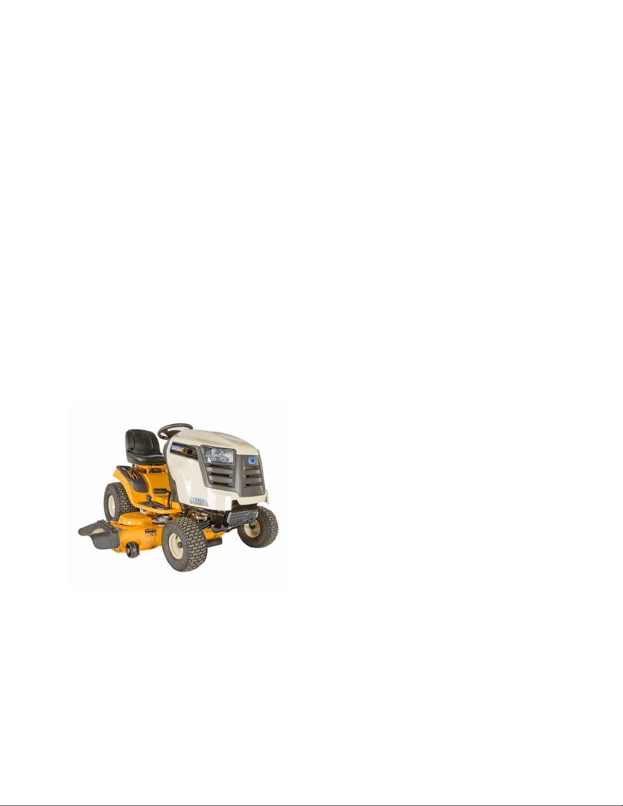
Description of the 900 series
The 900 series is a new tractor platform intr oduced in the 2009 season. This plat form replaces the traditional 600
series tractor.
New for the 900 series is:
• New stronger frame
See Figure 1.1.
Figure 1.1
• New hood and grill designs
• A new 42” timed deck
• A new 2 blade 46” deck
• Tighter turning radius
3
Page 10

LTX Tractors
Model and Serial Numbers
The model and serial number tag can be found under
the seat.
number as shown above.
The model number is 13AX90AR010 The break down of what the character mean is as follows:
See Figure 1.2.
The serial number is located to the right of the model
See Figure 1.2.
Model number
Figure 1.2
Serial number
1 ..............................................................................................Cuts grass
....3 ..........................................................................................Lawn tractor
.......A....................................................................................... Sales level/type of create
...........X............................ ... ... ... .... ... ... ... .... ............................. Engine code
.............9. ................................................................................Frame
.................0 ......................................... ... .... ... ... .......................Drive system
....................A.......................................................................... Hood style
.........................R.....................................................................Deck (S = 42”, T = 46”, P=50”, R=42” timed deck)
.............................056 ............................................................. Customer number
The serial number is 1J078H30003. The serial number reads as follows:
1 ..............................................................................................Engineering level
..J............................................................................................. Month of production (J = October)
.....07 .......................................................................................Day of the month
.........8 .....................................................................................Last digit of the year
...........H............................................................ ... .... ... .............Plant it was built in (Martin, TN)
..............3 ................................................................................Assembly line number
.................0003 ....................................................................... Build number of unit
4
Page 11
CHAPTER 2: ENGINE RELATED PARTS
This manual will cover the engine accessories that are manufactured by Cub Cadet.
IMPORTANT: Refer to the engine manufacturer’s manual for engine specific service information.
Muffler
Remove the muffler by following these steps:
NOTE: The muffler and the exhaust pipes are welded
together . They are replaced as one assembly.
1. Remove the hood and bumper by following the steps
described in Chapter 4: Body/Chassis.
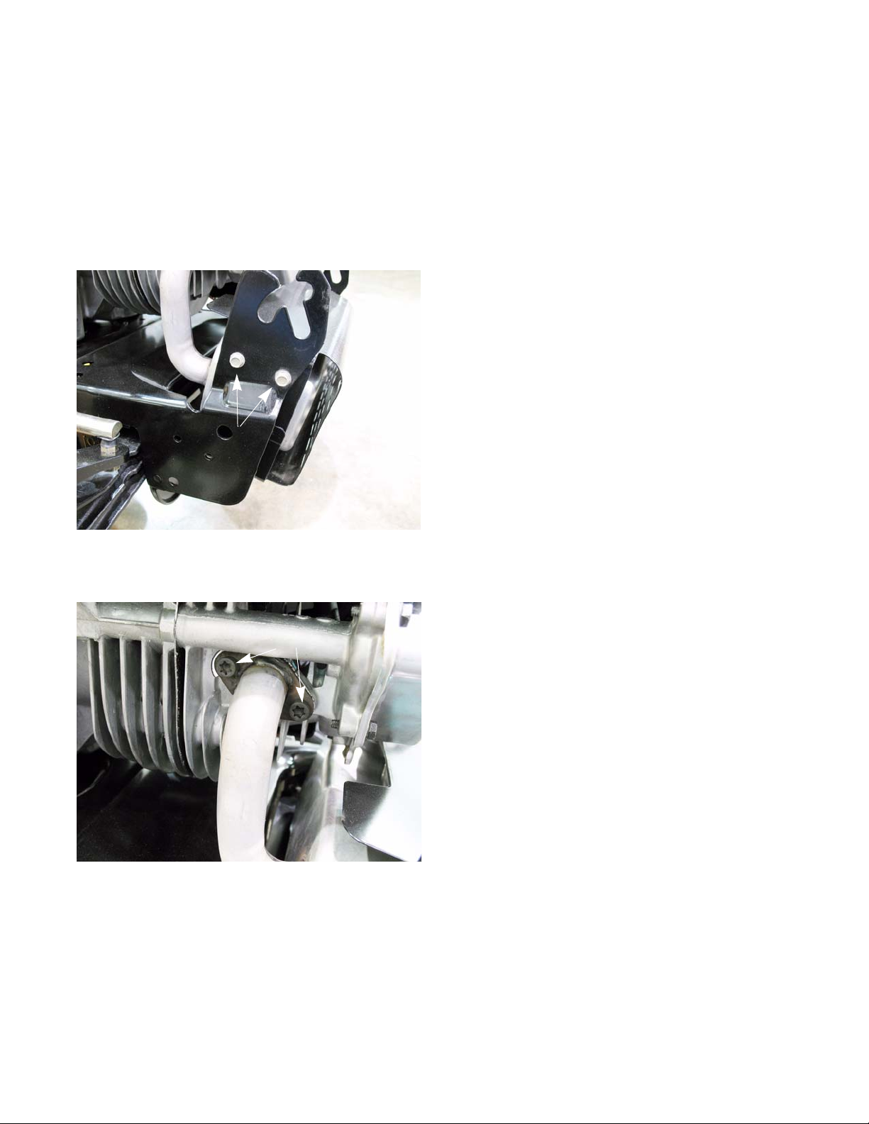
2. Remove the two screws on each side that secure th e
muffler guard bracket.
Screws
See Figure 2.1.
Engine Ralated Parts
Figure 2.1
Screws
Figure 2.2
3. Disconnect the muffler from the engine:
For single cylinder engines:
• Remove the two screws that secure the exhaust
pipe to the cylinder head.
See Figure 2.2.
5
Page 12
LTX Tractors
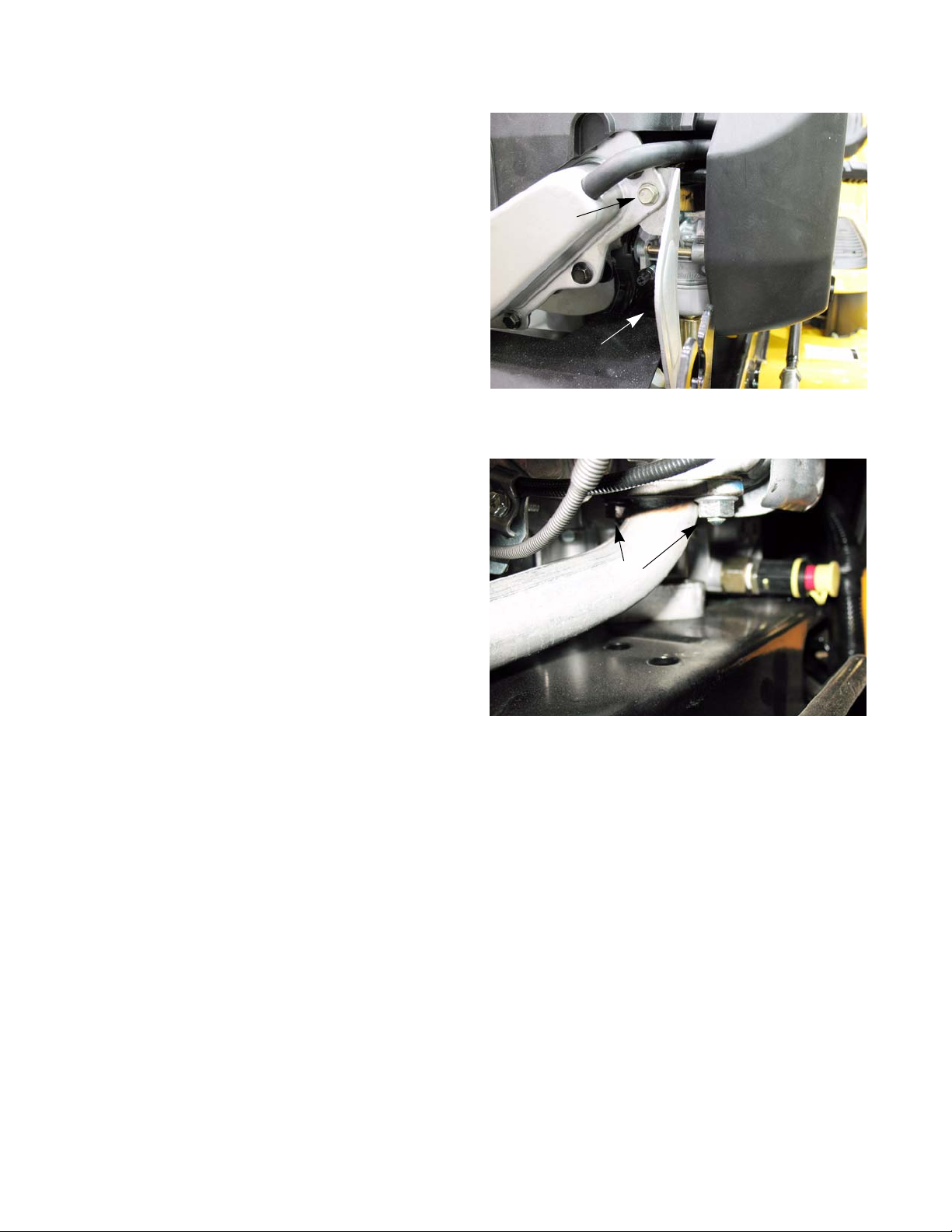
• Remove the screw that fastens the muffler support bracket to the cylinder head.
See Figure 2.3.
For twin cylinder engines:
Screw
Support bracket
Figure 2.3
• Remove the two nuts that secure each exhaust
pipe to the cylinder head. See Figure 2.4.
Nuts
Figure 2.4
6
Page 13
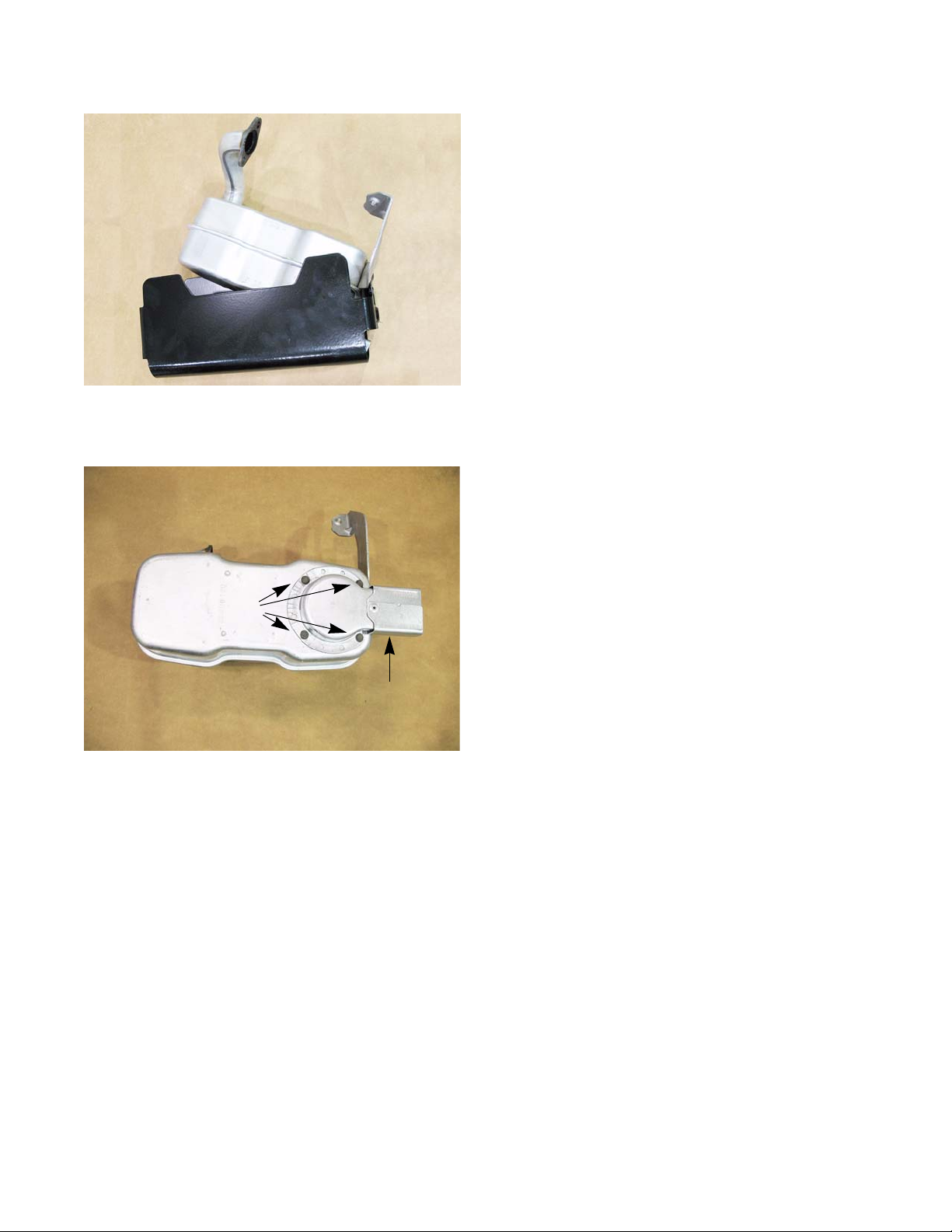
Figure 2.5
Engine Ralated Parts
4. Pull the muffler cover and muffler out together.
5. Rotate the muffler out of the muffler cover.
See Figure 2.5.
6. With the muffler on a work bench, remove the four
screws that hold the muffler deflector to the muffler.
See Figure 2.6.
Screws
Figure 2.6
7. Install the muffler by following the above steps in
reverse order.
8. Test run the tractor before returning to service.
Muffler deflector
7
Page 14
LTX Tractors
Fuel tank removal/replacement
Remove/replace the fuel tank by following these steps:
Gasoline and its vapors are extremely flammable. Use common sense when working around
! CAUTION! CAUTION
• Work in a well-ventilated area.
• Allow the engine to cool fully before starting work on the tractor.
• Eliminate any sources of possible ignition from the work area, including but not limited to: heat sources,
open flame, potential sparks.
• Clean-up any spilled fuel quickly and properly, disposing of cleaning materials in a way that will not produce a further fire hazard.
• Hold any drained fuel in an approved and safe
container.
1. Open the hood.
2. Drain the fuel in the fuel tank into an approved container.
the fuel system.
NOTE: The tank may be drained by mechanical
syphon or by disconnecting the fuel line from
the fuel filter.
3. Disconnect the fuel tank vent hose from the roll over
valve (if equipped).
4. Remove the four screws that secure the fuel tank
support rod.
5. Work the fuel tank support bracket off of the tractor
6. Slide the fuel tank out from between the dash and
the engine.
7. Remove the fuel line clamp and slide the fuel line off of the fuel tank nipple.
NOTE: The fuel tank has a barbed fitting. Anytime a fuel line is removed from a barbed fitting it should be
8. Install the fuel tank by following the above steps in reverse order.
9. Test run the tractor and check for leaks before returning to service.
See Figure 2.7.
replaced because of the damage caused to the fuel line liner.
Screws
Figure 2.7
8
Page 15
Fuel Line
Engine Ralated Parts
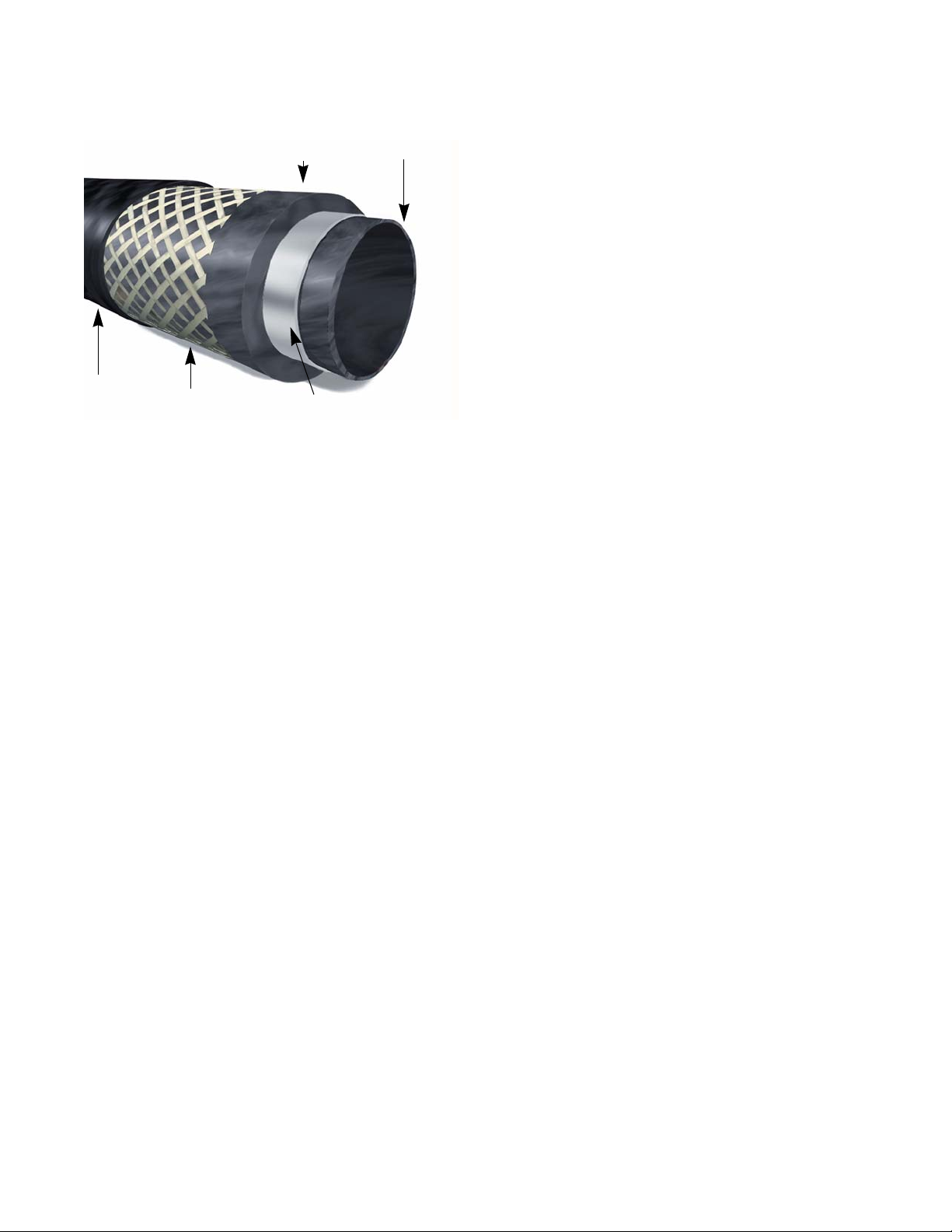
CSM Cover
Picture courtesy of Avon Automotive
NBR intermediate layer
Reinforcement
Figure 2.8
THV barrier layer
NBR inner liner
The fuel line used by Cub Cadet is GREENbarTM. This
is a multi-layer fuel line that meets the current EPA guidelines.
NOTE: This fuel line has a thin inner liner. If a tear forms in
this inner liner, fuel can get between the liner and
the hose. This will cause the liner to collapse, cut
ting off the fuel flow.
NOTE: Replace the fuel line only with GREENbarTM 700
series fuel line.
-
9
Page 16
LTX Tractors
%NGINE
%NGINE
#HARCOAL
CANISTER
6ENT
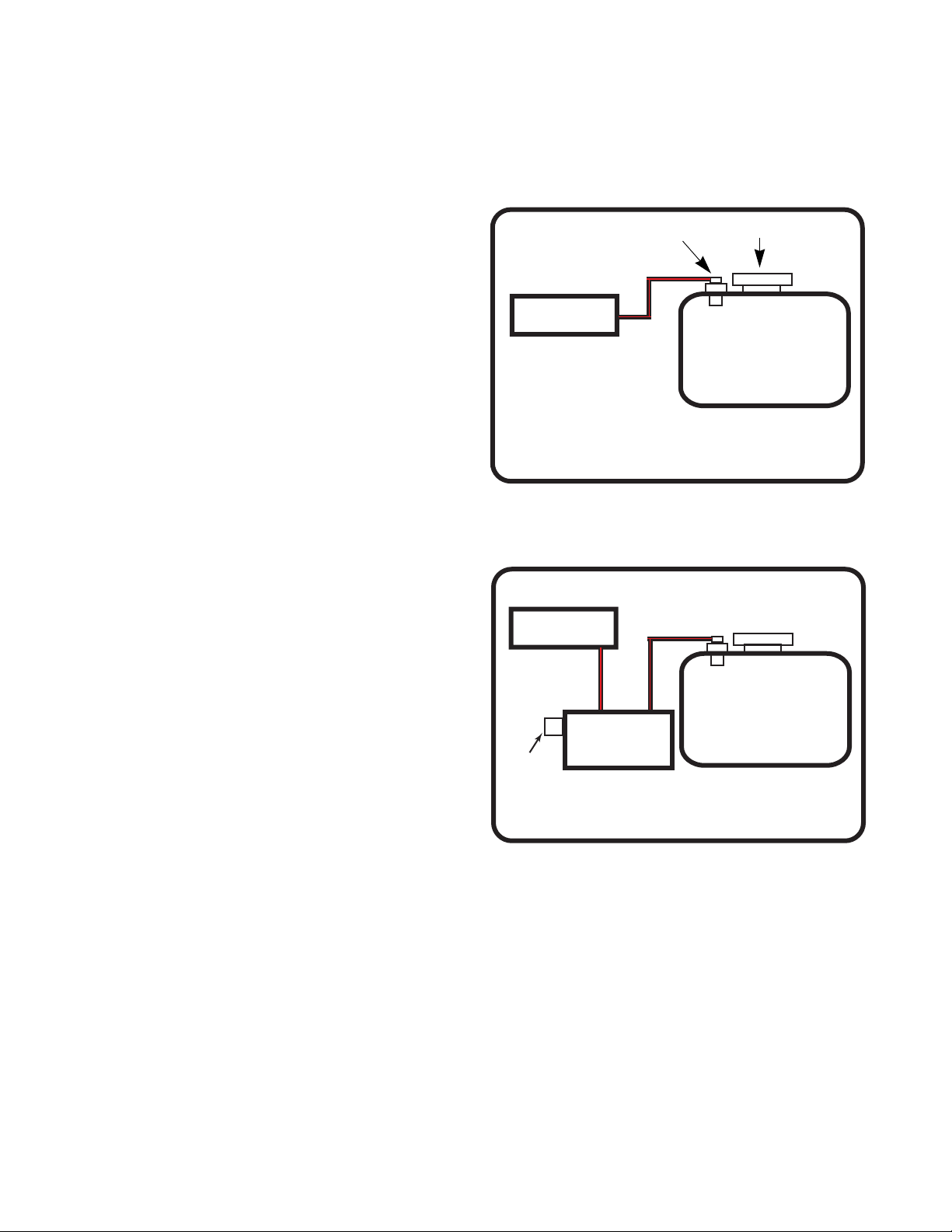
Evaporative (EVAP) emissions system
The EPA has enacted rules that regulate the amount of vapors an engine’s fuel system is allowed to vent to the
atmosphere. The rules are know as Tier III Emissions Standards. These rules apply to all engines built on or after 1/
1/2012. Some of the requirements of tier III emissions include:
• Tethered fuel caps.
• Unvented fuel caps.
• Low permeation (GREENbar
• Roll over valve vents
The fuel tank has an unvented fuel cap. The fuel tank
vents through the roll over valve. The vapors will flow
through the vent hose (black hose with a red trace) to the
engine.
connector, is a Cub Cadet system, meaning warranty and
parts are handled by Cub Cadet.
facturer, but on most engines the vent hose will go to the
air intake manifold.
See Figure 2.9.
The EVAP system, from the fuel tank up to the engine
The engine side of the system varies by engine manu-
TM
) fuel line
Roll over valve
49 state fuel system
Figure 2.9
Fuel cap
Fuel tank
NOTE: Units sold in California will have a charcoal
canister to further reduce the amount of
emissions that escape from the fuel system.
The fuel tank will vent through the charcoal
canister. The charcoal in the canister will act
as a filter and remove some of the vapors
that are venting out of the fuel tank.
A second vent hose connects the canister to
the engine. As the engine runs, the vacuum
in the intake manifold will draw the vapors
out of the charcoal, recharging it.
See Figure 2.10.
NOTE: A leak in the vent hose will allow dirt injec-
tion into the engine. This will not affect
engine performance until the dirt ingestion
has cause damage inside the engine.
Fuel tank
California fuel system
Figure 2.10
10
Page 17

Engine Ralated Parts
T roubleshooting
Symptom Cause
Engine starts, then dies A blockage in the vent hose.
The roll over valve is stuck closed.
Engine runs rich Raw gasoline in the charcoal canister (if equipped).
A blockage in the line between the charcoal canister (if
equipped) and the intake manifold.
Engine runs lean Wrong fuel cap installed.
Leak in the vacuum lines.
Gasoline vapor escaping from
the engine
The charcoal canister (if equipped) is saturated.
A blockage in the line between the charcoal canister (if
equipped) and the intake manifold.
Wrong fuel cap installed.
Leak in the vacuum lines.
11
Page 18
LTX Tractors
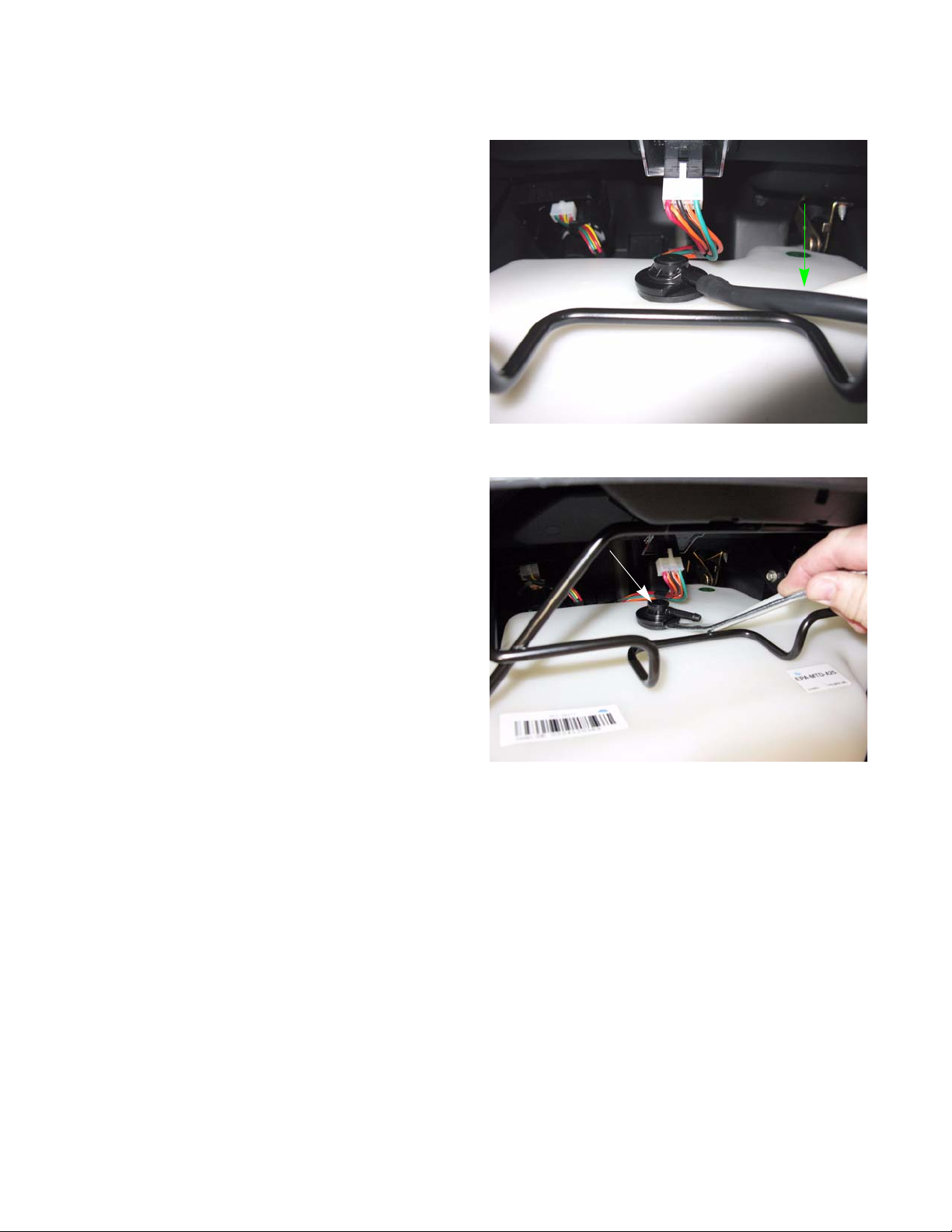
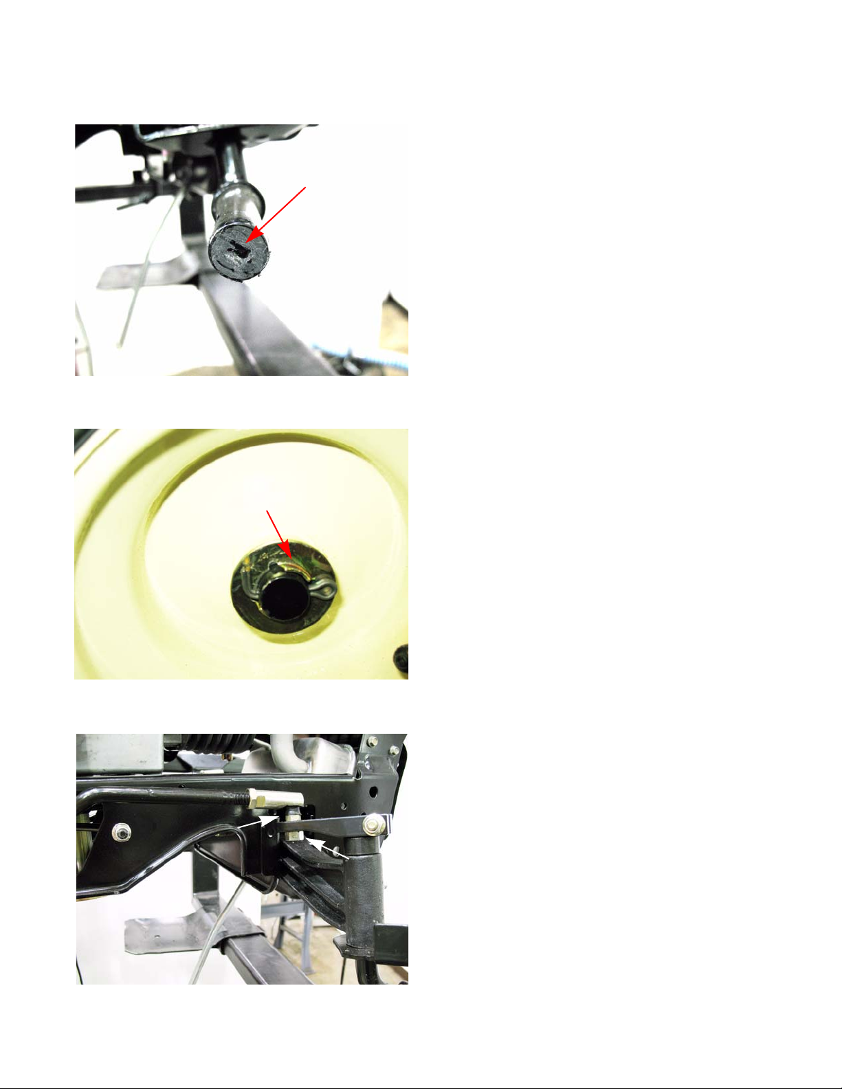
Roll over valve vent
To remove the roll over valve:
1. Open the hood.
2. Disconnect the vent hose. See Figure 2.11.
NOTE: The vent hose will have a red trace.
3. Gently pry the roll over valve out of the fuel tank.
See Figure 2.12.
4. Inspect the rubber grommet, replace if damaged.
To install the roll over valve:
Vent hose
Figure 2.11
Roll over valve
1. With the grommet on the roll over valve, install the
roll over valve by pressing it into the opening in the
tank.
2. Attach the vent hose to the roll over valve.
3. Test run the engine in a safe area befo re retur nin g
to service.
Figure 2.12
12
Page 19
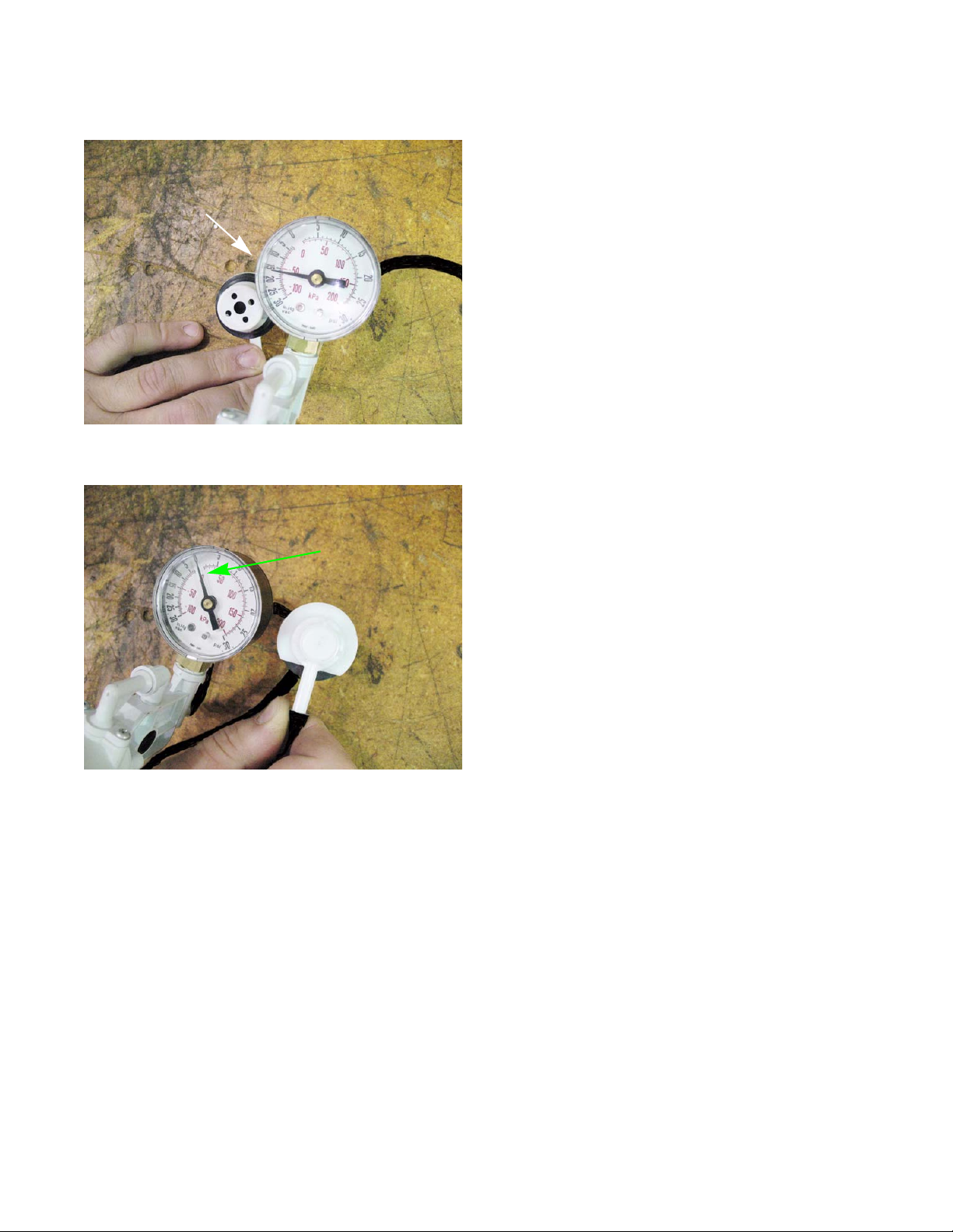
Testing the roll over valve
15 in.Hg.
Figure 2.13
Engine Ralated Parts
The roll over valve vent has two functions. The first
function is to vent the tank and the second function is to
close off the vent if the tank is inverted.
Test the roll over valve by:
1. Remove the roll over valve by following the steps pre viously described in this section.
2. Connect a vacuum pump to the roll over valve.
3. Hold the roll over valve in an inverted position.
4. Apply a vacuum to the roll over valve.
See Figure 2.13.
NOTE: The roll over valve should hold 15 in.Hg. for 15
seconds.
Zero reading
Figure 2.14
5. With the vacuum still applied, turn the roll over valve
over.
See Figure 2.14.
NOTE: The vacuum should be relieved.
6. If the results do not match what is listed above,
replace the roll over valve.
13
Page 20

LTX Tractors
14
Page 21
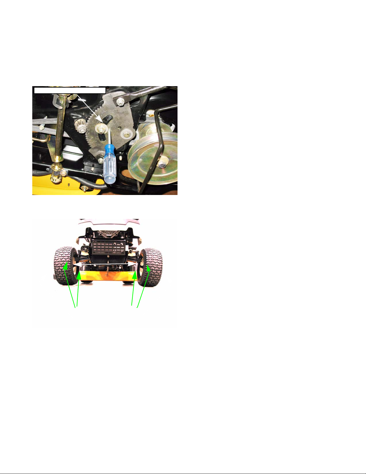
Steering alignment
Center the sector gear
CHAPTER 3A: STEERING
IMPORTANT: The front tires will have a “TOE-IN” between
1/16” and 1/4” to allow the unit to track properly.
1. Check the tire pressure in the front tires and make
certain that they are at approximately 14 PSI. The
rear tires should be at 10 PSI.
2. Place the unit on level ground.
3. Lower the deck lift lever to the lowest position.
4. Line up the centering hole in the sector gear with the
centering hole in the support plate, and insert a 1/4”
Phillips screw driver up through both.
See Figure 3A.1.
Steering
Figure 3A.1
Measure rim-to-rim at the front and back of rim
Measure rim-to-rim at the front and back of rim
Figure 3A.2
NOTE: The steering wheel should be in the straight for-
ward position. If it is not, remove the steering
wheel and reinstall it so that it is.
5. In front of the axle, measure the distance horizont ally
from the inside of the left rim to the inside of the right
rim.
See Figure 3A.2.
6. From behind the axle, measure the distance horizontally from the inside of the left rim to the inside of the
right rim.
7. The measurement taken in front of th e axle should be
between 1/16” and 5/16” less than the measurement
taken behind the axle. If not, perform the following
steps:
15
Page 22
LTX Tractors
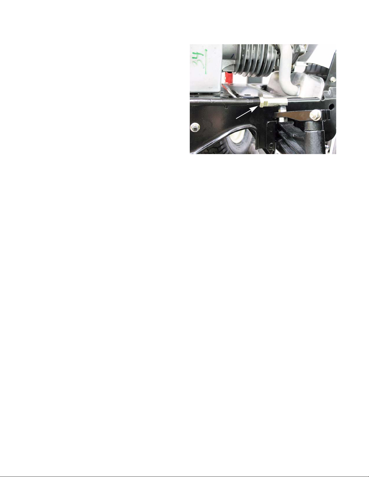
8. Loosen the jam nut at the rear of the right ball joint
that secures the ball joint to the drag link, using a 1/
2” wrench and an 11/16” wrench.
9. Remove the hex nut and lock washer, that secures
the right ball joint to the right axle assembly, using a
1/2” wrench and a 9/16 wrench.
10. Remove the right hand ball joint from the right hand
drag link.
1 1. Remove the left hand ball joint performing steps 8, 9
and 10 above.
12. Place the left and right tire assemblies in the straight
forward position.
13. Set the toe-in for the rim assemblies to 3/16”.
14. Thread the right hand ball joint onto the right hand
drag link until the mounting hole in the right hand axle assembly lines up with the ball joint.
NOTE: Count the number of turns the ball joint was rotated onto the drag link. This number should be within a
couple of turns of the left side. If there is more than a couple turns difference, then one or both of the
drag links are bent.
See Figure 3A.3.
Jam nut
Figure 3A.3
15. Secure the right hand ball joint to the right hand axle assembly with the lock washer and nut removed earlier,
using a 1/2” wrench and a 9/16” socket
16. Secure the right hand ball joint jam nut to the right hand drag link using a 1/2” wrench and an 11/16” wrench.
17. Install the left hand ball joint using steps 14, 15 and 16.
16
Page 23
Axles
Figure 3A.4
Identification mark
Steering
NOTE: The left and right axle have a “L” or a “R” stamped
on the end of the shaft for identification.
See Figure 3A.4.
1. Jack up the front end of the tractor and securely place
on jack stands.
2. Remove the front wheel by popping the hub cap off
with a flat head screw driver.
Castellated washer
Figure 3A.5
1/2” wrench
3. Remove the cotter pin and the castellated washer.
See Figure 3A.5.
NOTE: When installing the wheel, install a new cotter pin
in between the uprights of the castellated washer.
4. Remove the nut holding the drag link to the steering
block using a 1/2” and 9/16” wrench.
See Figure 3A.6.
Figure 3A.6
9/16” wrench
17
Page 24
LTX Tractors
5. Support the axle and remove the steering block
using two 1/2” wrenches.
NOTE: The SLT models do not have a spacer.
See Figure 3A.7.
Steering block
Spacer
Figure 3A.7
6. Remove the spacer and lower the axle out of the
pivot bar.
NOTE: Starting in the 2010 season, some tractors
will be equipped with a stamped pivot bar.
These tractors will have plastic bushing
where the axle rides inside the pivot bar.
See Figure 3A.8.
NOTE: The procedure to remove this axle is the
same as previously described. When install
ing the axle, install new upper and lower
bushings.
7. Install the axle by following the previous steps in
reverse order.
8. Perform a wheel alignment by following the steps described in the steering a lignment section of this chapter.
9. Test run the tractor in a safe area before ret ur ning it to ser vice.
Bushings
-
Figure 3A.8
18
Page 25
Sector gear and steering pinion gear
Steering Pinion Ge ar
Flange Lock Nut
Figure 3A.9
Remove the washer
Steering
If you are replacing the sector gear or steering pinion
gear, check the condition of both gears for any wear or
damage. It may be wise to replace both as a set.
1. Remove the cutting deck by following the steps
described in Chapter 8: Cutting Decks and Lift Shaft
2. Jack up the front end of the tractor and securely
place on jack stands.
3. Remove the flange lock nut securin g the stee ring pi nion gear to the steering shaft using an 1 1/16” socket.
See Figure 3A.9.
Lift up on the steering shaft
Figure 3A.10
Remove the hex
bushing
4. Slide the steering pinion gear off of the steering shaf t.
5. Lift up on the steering shaft an d remove the washer.
See Figure 3A.10.
6. Push the steering shaft up through the frame of the
tractor.
7. Remove the hex bushing. See Figure 3A.11.
Figure 3A.11
19
Page 26
LTX Tractors
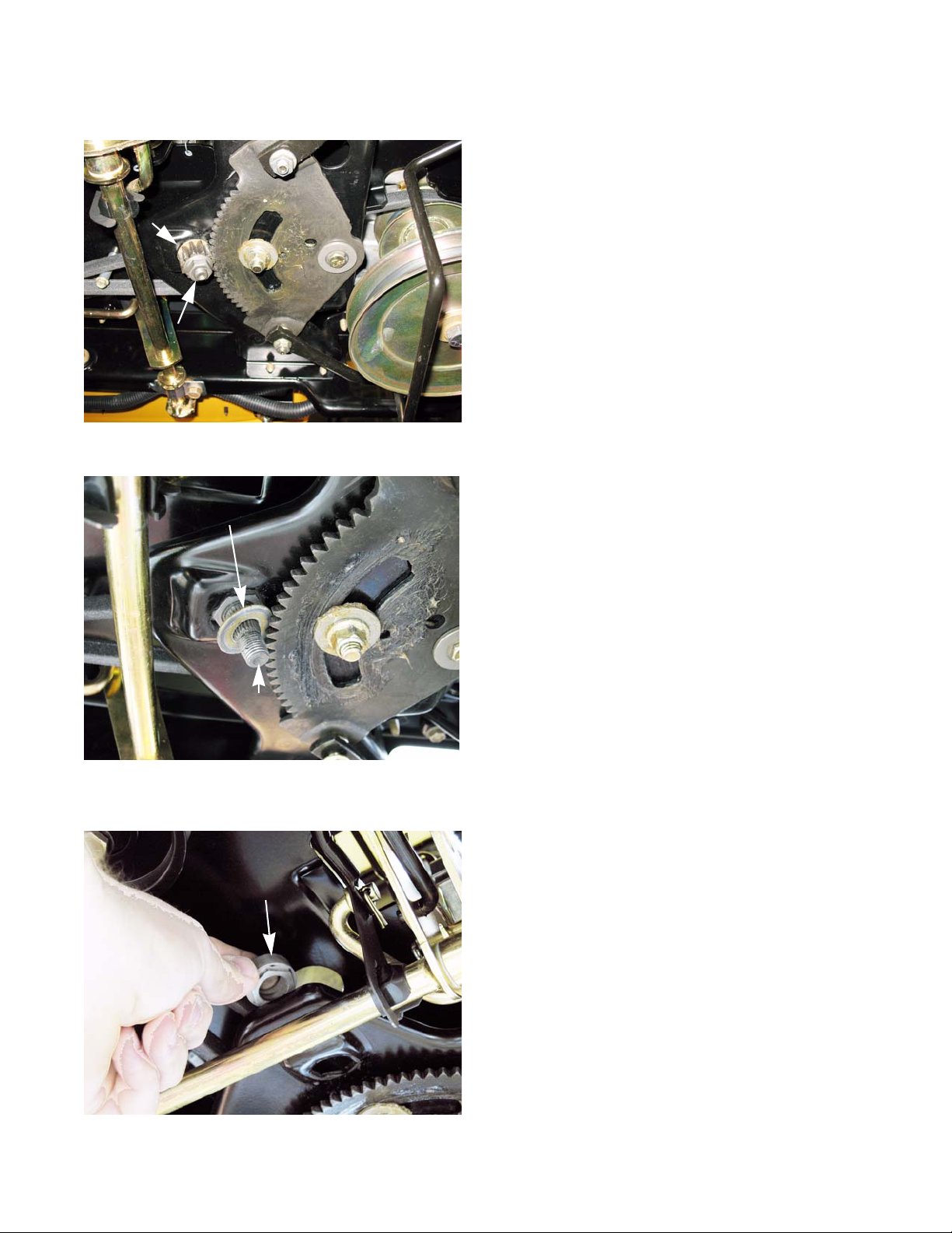
8. Remove the drag links from the sector gear.
9. Remove the six screws that secure the steering
plate to the frame.
10. Remove the steering plate.
See Figure 3A.12.
Remove these screws on each side
Figure 3A.12
11. Remove the hex cap screw, shoulder spacer and
hex nut in the middle of the sector gear using two 9/
16” wrenches.
NOTE: Note the order the sp acers and washer were
removed so that they can be installed prop
erly. See Figure 3A.14.
12. Remove the bolt that the sector gear pivots on using
two 9/16” wrenches.
NOTE: When installing the sector gear, coat the
sector gear and the steering plate with a
high quality lithium grease.
13. Install the steering and steering pivot gears by following the previous steps in reverse order.
See Figure 3A.13.
-
See Figure 3A.13.
sector gear
Steering plate
Figure 3A.13
14. Perform a wheel alignment by following the steps
described in the steering alignment section of this
chapter.
15. Test run the tractor in a safe area before returning it
to service.
20
Figure 3A.14
Page 27
Steering shaft and he x bushing
Figure 3A.15
Steering
To remove the steering shaft or to replace the hex bushing:
1. Remove the cutting deck by following the steps
described in Chapter 8: Cutting Decks and Lift Shaft
2. Jack up the front end of the tractor and securely
place on jack stands.
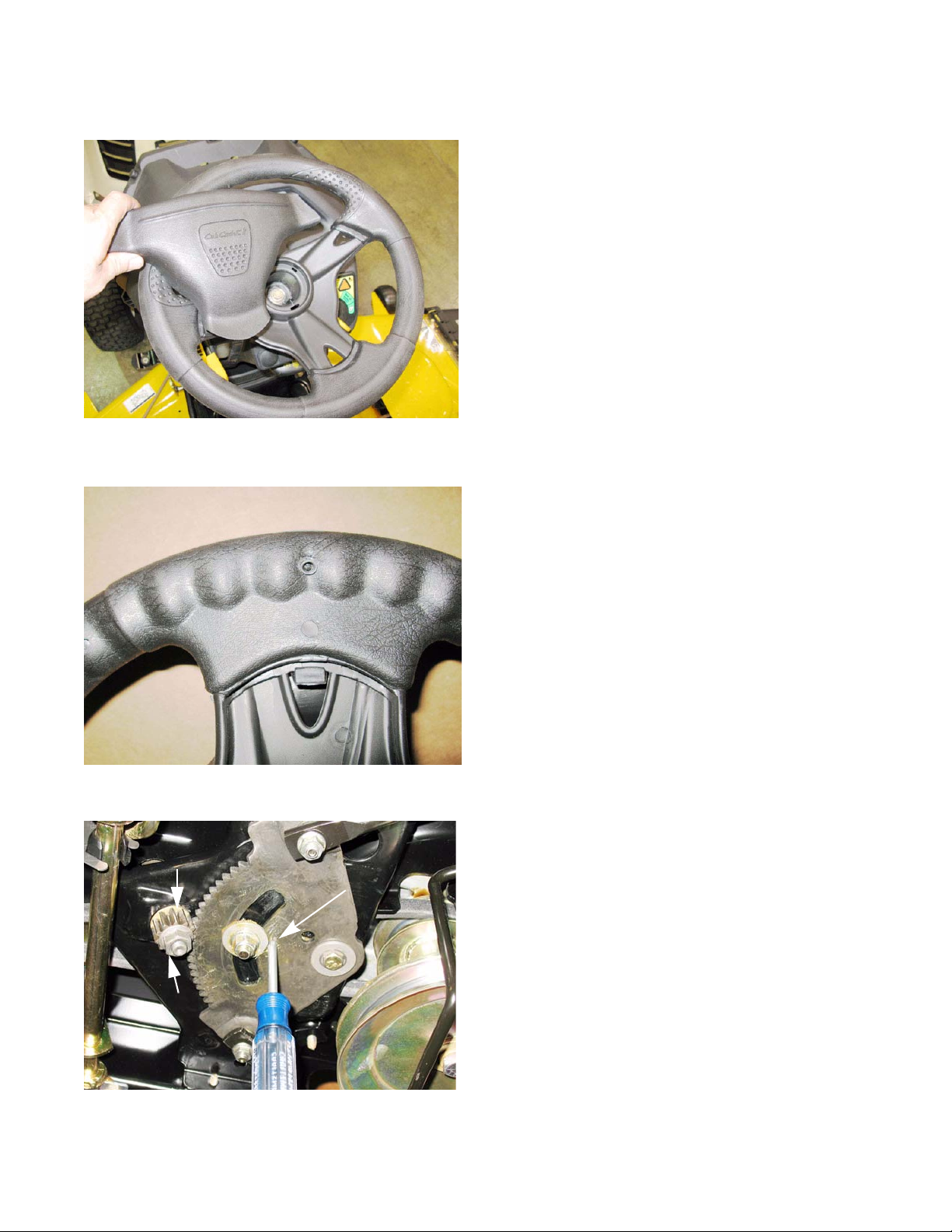
3. Remove the steering wheel
3a. Remove the cover from the center of the steer-
ing wheel. See Figure 3A.15.
Figure 3A.16
Steering Pinion Ge ar
Flange Lock Nut
Alignment hole
NOTE: The cover can be released by prying-in on the
lock-tabs on the under-side of the steering wheel.
See Figure 3A.16.
3b. Remove the bolt that holds the steering wheel
to the steering shaft using a 1/2” wrench.
3c. Lift the steering wheel off of the steering shaft.
.
4. Remove the flange lock nut securin g the stee ring pi nion gear to the steering shaft using an 11/16” socket.
See Figure 3A.17.
NOTE: If the steering shaft rotates while removing the nut,
insert a pin punch or a #2 phillips screwdriver into
the alignment hole in the sector gear. This will lock
the steering shaft in place, allowing the nut to be
removed.
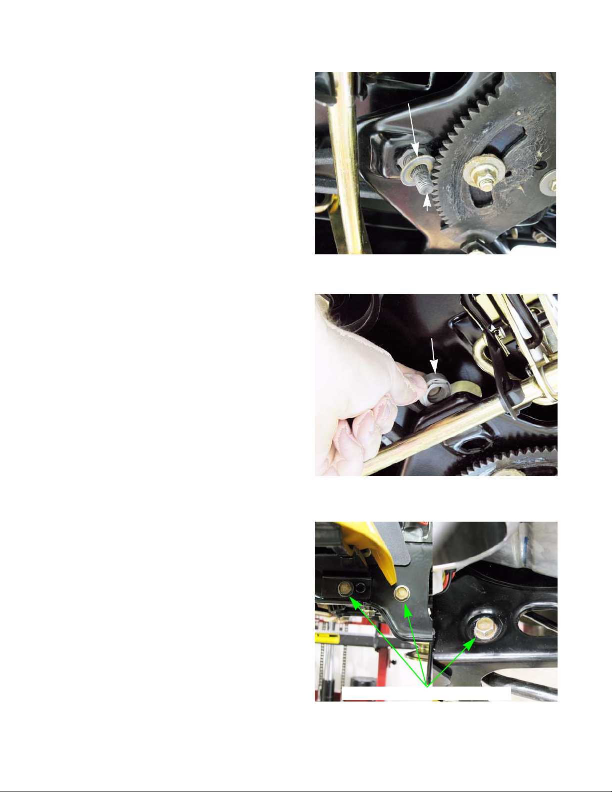
5. Slide the steering pinion gear off of the steering
shaft.
Figure 3A.17
21
Page 28
LTX Tractors
6. Lift up on the steering shaf t and remove the washer.
See Figure 3A.18.
7. Push the steering shaft up thro ugh the frame of the
tractor.
8. Remove the hex bushing. See Figure 3A.11.
NOTE: Replace the hex bushing every tim e th e
steering shaft is removed.
9. Remove the drag links from the sector gear.
Remove the washer
Lift up on the steering shaft
Figure 3A.18
Remove the hex
bushing
10. Remove the six screws that secure the steering
plate to the frame.
11. Remove the steering plate.
NOTE: The steering shaft will come out with the
steering plate..
12. Install the steering shaft by following the above
steps in reverse order.
13. Test run the tractor in a safe area before returning it
to service.
22
See Figure 3A.12.
Figure 3A.19
Remove these screws on each side
Figure 3A.20
Page 29
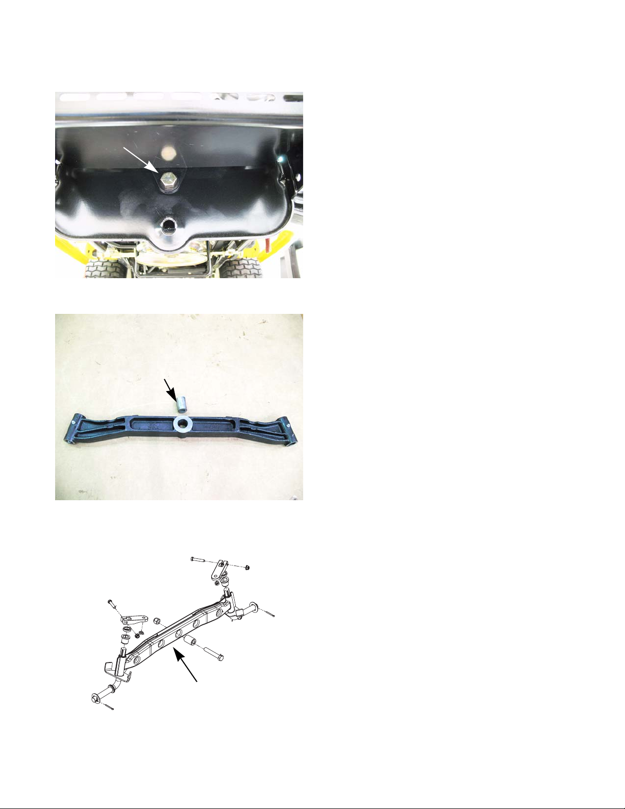
Pivot bar
Remove this bolt
Figure 3A.21
Steering
To remove/replace the pivot bar:
1. Jack up the front end of the tractor and securely place
on jack stands.
2. Remove the axles by following the procedures
described in the axle section of this chapter.
3. Slide the front deck link out of the frame.
4. Support the pivot bar.
5. Remove the pivot bar pivot bolt using two 3/4”
wrenches.
6. Slide the pivot bar out of the frame.
See Figure 3A.21.
Spacer
Figure 3A.22
NOTE: There is a spacer in the center of the pivot bar. It
must be in place when installing the pivot bar.
See Figure 3A.22.
NOTE: Starting in the 2010 season, there will be a
stamped pivot bar on some models. The proce
dure to remove it is the same as the cast iron pivot
bar described in the previous steps.
See Figure 3A.23.
7. Install the pivot bar by following the previous steps in
reverse order.
-
Stamped pivot bar
Figure 3A.23
NOTE: Apply high quality grease to the frame, spacer an d
the pivot bar.
8. Preform a wheel alignment by following the steps
described in the steering alignment section of this
chapter.
9. Test run the tractor in a safe area before returning it
to service.
23
Page 30

LTX Tractors
24
Page 31

Electronic Power Steering
CHAPTER 3B: ELECTRONIC POWER STEERING
NOTE: The basic steering system, such as the tie rod ends, drag links axles, etc., is covered in Chapter 3A:
Steering.
In 2012, Cub Cadet introduced the Electronic Power Steering (EPS) system on the Cub select models of the LTX
series of tractors. The EPS provides an electric assist to the steering wheel.
The EPS is a system consisting of three sub-assemblies: the rubber torsion coupling, the EPS module and
the EPS motor & gearbox. They form an assembly that is inserted between the steering shaft and sector gear. The
EPS system is treated as one part.
DO NOT loosen or separate any of
EPS Module
! CAUTION! CAUTION
sion coupler when the EPS assembly is built at
the factory . Once it has been calibrated, it can no t
be re-calibrated. Any shift between the coupling
and the module will result in the EPS auto-steering, which is a very unsafe condition.
the EPS components.
The module is calibrated to the tor-
EPS motor & gearbox
Rubber torsion coupling
Figure 3B.1
Rubber Torsion Coupling
The steering shaft connects the steer ing wheel to the EPS system through the rubber torsion coupling. As the
steering wheel is turned, it applies force to the coupling. The force causes the torsion coupling to twist or torque. The
amount the coupling torques is determined by the amount of force applied to the steering wheel, the more force
applied to the steering wheel, the more the coupling twists.
NOTE: The rubber torsion coupling has hard stops bui lt into it. If the force applied to the steering wheel causes
the coupling to hit its hard stops, the steering input will transfer through the module into the steering
gearbox. This allows manual steering if the EPS system fails.
EPS Module
The EPS module controls the power supplied to the EPS motor. It senses the amount of force that is being
applied to the steering wheel by monitoring the torsion coupling. The module will ramp up the power supplied to the
EPS motor as the force applied to the steering wheel increases. The EPS motor will reach full power within a couple
of degrees of deflection of the torsion coupling.
NOTE: Auto-steering is a condition were
the EPS will turn the wheels to one
direction, once the engine is
started. This happens because the
calibration is off and the EPS thinks
there is a steering input when there
isn’t.
The EPS comes with a 4 year warranty. If there is
a failure with the system, replace the entire system as an assembly.
25
Page 32

LTX Tractors
EPS motor & gearbox
The steering input passes through the torsion co upling
and module into the gearbox. The gearbox then passes
the input force to the output shaft connected to the steer
ing housing.
-
EPS module
The EPS motor assists in turning the input shaft by
driving a set of planetary gears. The planet ary gears drive
a worm shaft. The worm shaft drives a worm gear on the
output shaft.
IMPORTANT: DO NOT open or service the steering
gearbox.
DO NOT drop or hammer on any of
! CA UTION! CA UTION
trapped between the torsion coupling and the
EPS module. If this sensor shifts, it can cause an
auto-steer condition.
the EPS components.
There is a torque senor that is
Steering shaft
coupler
Torsion coupling
EPS motor
EPS motor
output shaft
EPS gearbox
Worm gear
Figure 3B.2
Planetary gears
Worm shaft
26
Worm gear
Figure 3B.3
Page 33

Troubleshooting the EPS (without the 725-05419 EPS tester)
The first step in troubleshooting the EPS system is to
understand how it works.
Electronic Power Steering
See Figure 3B.4.
(QJLQHVKXW
GRZQFLUFXLWV
,JQLWLRQPRGXOH
Figure 3B.4
,JQLWLRQPRGXOH
*5281'
0$*1(72
%$77(5<
*5281'
0$*1(72
%$77(5<
• A constant 12 volts is supplied by the battery
through a 40 amp fuse in the fuse box.
• The EPS is grounded through the green wire.
• The EPS senses the ignition pulses from the ignition module primary windings throug h th e ye llow
wire with a white trace.
NOTE: On tractors with Kohler engines with a Digital
Spark Advance (DSA) ignition, A diode is installed
to protect the ignition module from any stray volt
age that may come from the engine shut down circuits. A white wire carries a clean spark signal to
the EPS to turn it on.
See Figure 3B.5.
• Once the EPS determines that the engine is running (by sensing the ignition pulses from the ignition coil) it will turn on.
• The EPS will power the EPS motor as it senses
input from the steering wheel.
To troubleshoot the EPS assembly:
1 Check the 40 amp fuse in the fuse box.
See Figure 3B.6.
NOTE: If the fuse is blown, check for a short in the red
wire that goes to the EPS assembly before replac
ing the fuse.
-
-
40 amp fuse
Figure 3B.5
Figure 3B.6
The technician needs to determine if there is a mechanical bind in the steering system or an EPS issue. The easiest way to rule out a binding steering system is to:
2. Remove the steering pinion gear by following the
procedures described in Chapter 3: Steering.
3. Start the engine.
4. Operate the steering wheel.
• If the steering wheel now moves freely , th e issue is
downstream of the pinion gear. The most likely
suspect would be axles frozen to the pivot bar.
• If the steering wheel is still hard to operate, isolate
the problem to either the EPS assembly or the cir
cuits that go to the EPS assembly.
NOTE: To protect the EPS module, it will turn off if the
steering input is held at a hard stop for more than 2
seconds. The EPS will turn back on once the input
is released from the hard stop.
-
27
Page 34

LTX Tractors
NOTE: Before troubleshooting any electrical circuit on a tractor, always make sure the battery is fully charged.
NOTE: The EPS assembly has constant battery power and is not controlled by the ignition switch.
To troubleshoot the EPS assembly:
5. Place the tractor on flat, level ground.
6. Remove any attachments that may be on the tractor.
7. Set the parking brake.
8. Turn the steering wheel so that the wheels are
pointing straight forward.
9. With the ignition key in the off position, open the
hood.
10. Locate, but do not disconnect, the EPS harness
connector underneath the fuel tank.
See Figure 3B.7.
EPS connector
11. Check for battery voltage at the red wire:
11a. Set the Digital Multimeter (DMM) to the DC
volts scale.
11b. Measure the battery voltage across the battery terminals
NOTE: If the battery voltage is < 12.6 volts, charge the battery before continuing.
11c. Connect the black (-) lead of the DMM to the negative post of the battery.
1 1d. Back probe EPS harness connector at the red wire with a black trace, using the red (+) lead of the DMM.
NOTE: The DMM should read battery voltage.
12. Check the ground to the EPS: See Figure 3B.8.
12a. Set the DMM to the DC volts scale.
12b. Connect the red (+) lead to the p ositive post of
the battery.
12c. Back probe EPS harness connector at the
green or black wire, using the black (-) lead of
the DMM.
NOTE: The DMM should read battery voltage. If it
does not, disconnect the EPS harness. If
you now have battery voltage at the EPS
harness connector (tractor side), there is a
short in the EPS assembly. If not, repair the
tractor harness.
Black wire
Figure 3B.7
Figure 3B.8
28
Page 35

Red wire
with black trace
Electronic Power Steering
13. Check the current draw of the EPS assembly.
13a. Leave the DMM connected to the ground wire
on the EPS and the battery.
13b. Place an amp clamp meter on the red wire with
a black trace.
NOTE: Cut the tape that seals the loom at the EPS con-
nector end of the harness and slide th e loom off of
the wires to attach the amp clamp.
13c. Start the tractor.
NOTE: The voltage reading on the DMM should now read
over 13 volts. If it does not, repair the charging cir
cuit before proceeding with troubleshooting the
EPS system.
See Figure 3B.9.
-
Figure 3B.9
NOTE: If the voltage drop s below 13 volt s and the current draw does no t rise above 15 amp s, repair the circuit
suppling voltage to the EPS before proceeding with tr oubleshooting the EPS system.
NOTE: If the voltage drops below 13 volts and current draw is more than 15 amps, the problem is inside the
EPS assembly and it must be replaced.
13e. Turn off the tractor.
5 volt
reticle
13d. Without sitting on the tractor, turn the steering
wheel a quarter turn back and forth. Watching
the voltage reading on the DMM and the current
reading on the amp clamp while doing this.
14.Remove the DMM and the amp clamp meter.
15.Check the input from the ignition module.
15a. Connect the ground lead of an oscilloscope to a
good ground on the engine block.
15b. Back probe the EPS harness connector at the
yellow wire with a white trace using the positive
(+) lead of the oscilloscope.
15c. Start the engine.
16. The oscilloscope should show a pulsed signal. The
bottom or resting phase of each pulse must be below
5 volts. The peak of each pulse must be over 5 volts.
See Figure 3B.10.
Figure 3B.10
17. The pulses must be at 9 Hertz (cycles/second) or
higher (engine needs to be >490 RPM).
18. If the resting phase of the pulse is above 5 volts,
there is a short in the safety circuit of the tractor that
is pulling up the voltage of the ignition module.
29
Page 36

LTX Tractors
NOTE: A voltage spike over 18.5vdc +/- 1.2v @70°F will cause the voltage regulator to shut down. The regula-
tor must be disconnected, then re-connected to reset it.
NOTE: A sustained voltage over 25 volts will damage the EPS module.
IMPORTANT: Loose battery cables or disconnecting jumper cables while the engine is running will create a
high voltage spike that will damage the EPS system.
NOTE: If the results are within the specified ranges or if the amperage draw is higher the n expected, check for
a mechanical bind by:
19. Remove the EPS assembly.
20. Check the steering shaft bushings.
NOTE: Cocked steering shaft bushing will bind the steering shaft, mimicking a bad EPS. Fix the bushings
before condemning the EPS.
21. If nothing is in a bind, replace the EPS assembly.
Troubleshooting the EPS (with the 725-05419 EPS Tester)
To troubleshoot the EPS using the 725-05419 EPS Tester:
1. Connect the red lead of the EPS Tester to the positive post of the battery .
2. Connect the black lead of the EPS Tester to the
negative post of the battery.
NOTE: A green LED and a blue LED should be illu-
minated. If they are not, the tester is malfunctioning.
NOTE: If a red LED illuminates when the tester is
connected to the EPS, the EPS has a short
and has blown the fuse on the tester.
3. Disconnect the EPS harness connector underneath
the battery.
4. Plug the EPS Tester into the connector on the EPS
assembly.
NOTE: The 725-05419 EPS Tester comes with a jumper harness, to be used on tractors with the battery unde r
the seat, so that the tester can reach the EPS assembly.
5. Start the engine.
6. Operate the steering wheel.
• If the steering wheel turns easily, the EPS is not the issue. Refer to the previous section to check the trac-
tor’s electrical system.
Green LED
Blue LED
Figure 3B.11
• If the steering wheel is still hard to turn:
a. Remove the EPS assembly.
b. Reconnect the EPS tester to the EPS assembly by following the procedures described in the EPS
removal section of this chapter.
c. Rotate the input shaft of the torsion coupler. If it rotates with minimal effort the EPS is working.
d. Check for a mechanical bind in the steering system. If it’s hard to turn, the EPS is faulty.
30
Page 37

EPS motor
Figure 3B.12
Electronic Power Steering
To remove/replace and test the EPS motor:
NOTE: The EPS system has a 4 year warranty. DO NOT
remove the EPS motor to test it within the warranty
period. Outside of the warranty period, the EPS
motor can be replaced separately from the EPS
assembly.
1 Remove the EPS assembly by following the proce-
dures described in the EPS removal section of this
chapter.
2. Disconnect the EPS motor harness from the EPS
module.
3. Remove the two screws that secure the motor base
to the EPS, indicated by the arrows in
using a 3/8” wrench.
4. Lif t the motor assembly off of the EPS.
Figure 3B.12,
Red wire
Black wire
Figure 3B.13
5. Mount the motor in a vise.
NOTE: Position the motor so that the vise jaws clamp the
motor base, to prevent damage to the motor.
6. Attach the black wire from the motor to the negative
side of a 12 volt power supply capable of producing
40 amps.
NOTE: The tractor’s battery or a jum p er box ca n be use d
as a power supply.
7. Attach the red wire from the motor to the positive
side of the power source.
NOTE: The motor should spin. If it does not, replace the
motor.
31
Page 38

LTX Tractors
8. Inspect the EPS motor gasket. If it is damaged,
replace it.
NOTE: Do not use a gasket sealant/adhesive on the
EPS motor gasket.
9. Remove the sun gear from the EPS motor.
10. Install the sun gear into the planetary gear set.
Sun gear
Figure 3B.14
11. Install the EPS motor.
NOTE: While installing the EPS motor, align the
motor pigtail with the EPS motor harness.
12. Install the EPS assembly in the tractor by following
the procedures described in the EPS removal sec
tion of this chapter, in re verse order.
13. Test run the tractor in a safe area before returning it
to service.
NOTE: Do not put a tractor into service with any
safety or control features that are not work
ing properly.
-
-
EPS motor pigtail
Harness
Figure 3B.15
32
Page 39

EPS removal/replacement
Loosen
Electronic Power Steering
To remove/replace the EPS assembly:
1 Remove the hood, dash and fender by following the
procedures described in Chapter 4: Body Panels.
2. Remove the fuel tank by following the procedures
described in Chapter 2: Engine Related Parts.
3. Remove the steering pinion gear by following the
procedures described in Chapter 3: Steering
4. Disconnect the EPS harness connector.
Steering coupler
Steering shaft
Remove
Figure 3B.16
Figure 3B.17
5. Loosen the top nut a nd bolt of the stee ring shaf t coupler using a pair of 1/2” wrenches.
6. Remove the lower nut and bolt from the steering
shaft coupler.
NOTE: It may be necessary to drive the bolt out with a
punch.
7. Lift the steering shaft off of the EPS.
NOTE: It will probably be necessary to pry the steering
shaft coupler off of the EPS.
! CAUTION! CAUTION
nents can cause the calibration of the EPS to
shift, resulting in an auto-steer condition.
See Figure 3B.16.
See Figure 3B.17.
DO NOT hammer on any of the
EPS components.
Hammering on the EPS compo-
33
Page 40

LTX Tractors
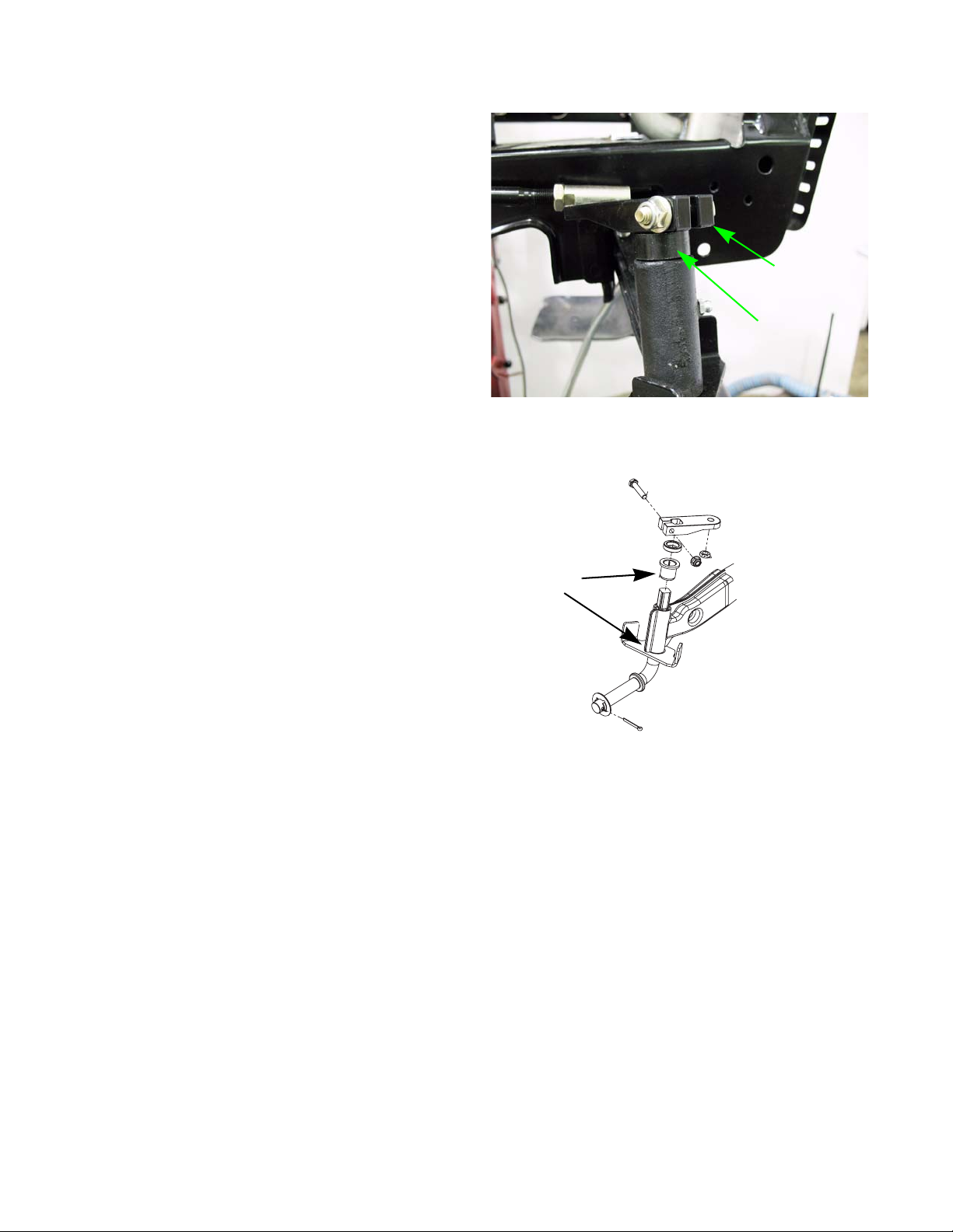
8. Remove the two screws securing the left dash support to the frame using a 3/8” wrench.
See Figure 3B.18.
9. Slide the left dash support off of the EPS motor.
10. Remove the two screws securing the EPS bracket
to the frame.
Screws
Figure 3B.18
11. Lift the EPS out of the tractor.
NOTE: The EPS output shaft will pass through a
spacer, and a bushing.
12. Install the EPS by following the previous steps in
reverse order.
NOTE: The washer that goes in-between the pinion
gear and the steering housing must be held
in place, under the tractor, while inserting the
EPS into the steering housing.
13. Test drive the tractor in a safe area before returning
it to service.
NOTE: Do not put a tractor into service with any
safety or control features that are not work
ing properly.
See Figure 3B.19.
-
Spacer
Bushing
Figure 3B.19
34
Page 41

Body Panels
CHAPTER 4: BODY PANELS
What is covered by this chapter
The intent of this chapter is to describe the removal and disassembly of the major body panels on the tractor.
•Hood
•Seat
• Fenders
• Dash panel
Figure 4.1
“A” style hood
NOTE: It is not absolutely necessary to remove the mow-
ing deck for any procedures covered in this section. The technician may choose to remove the
mowing deck so that it is easier to reach some
parts of the tractor.
NOTE: The hood described in this section is the “A” style
hood. Other styles may be produced for different
markets (e.g.: over-seas) or future style changes.
See Figure 4.1.
35
Page 42

LTX Tractors
Hood
Hood removal:
1. The hood is front-hinged. See Figure 4.2.
2. Open the hood by lifting the rear edge to tilt it forward.
3. Disconnect the headlight wires. See Figure 4.3.
NOTE: The ground terminals and powe r te rm ina l s
on the headlights are two different sizes.
The green wires (ground) fit the larger termi
nals. The red wires (power) fit the smaller
terminals.
Lift here
Figure 4.2
Inset: headlight detail
4. The hood hinges on a pair of shoulder bolts th at fit
into slots in the hood bracket.
5. The hinge travel is limited by a tab that fits into a
channel in the hood bracket.
6. Open the hood far enough to align the tabs with the
slots, then lift the hood off of the tractor.
See Figure 4.4.
36
Figure 4.3
Tab
Figure 4.4
Slot
Channel
Shoulder bolt
Page 43

Hood components: Headlight removal
Figure 4.5
Single-pin 1156-style lamp
Socket
Body Panels
1. With the spade terminals disconnected, rotate the
lamp holder (socket) to release it from the grill
assembly.
2. Rotate the bulb to release it from the socket. See
Figure 4.6.
See Figure 4.5.
Ground terminal
Power terminal
Figure 4.6
3. Install the replacement lamp following the above
steps in reverse order.
37
Page 44

LTX Tractors
Hood components: side vent removal
1. Carefully pry the vent free of the lock tabs.
See Figure 4.7.
2. Pull the vent out of the hood assembly.
3. Install the hood side vent by pressing it into the
hood side opening until the lock tabs click into
place, securing the vent.
2 lock tabs on top
2 lock tabs on bottom
Figure 4.7
38
Page 45

Hood components: grill removal
Body Panels
Slotted mounting hole
Screw +
washer
Large Screws
Figure 4.8
Grill
Pivot bracket
1. Remove the hood assembly from the tractor, and
place it on a stable work surface.
2. Loosen, but do not remove the screws that hold the
upper corners of the grill to the hood using a 3/8”
wrench.
3. Remove the two screws that hold the pivot bracket
and grill to the hood assembly using a 1/2” wrench.
See Figure 4.9.
See Figure 4.8.
Hood
Grill
Locating tab
Figure 4.9
Figure 4.10
Lock tabs
4. Once removed, the headlight lens may be removed
for cleaning by carefully prying the two lock tabs at
the inner edge.
NOTE: The locating tab at the outer edge of each len s has
no locking feature.
5. Assemble and install the grill by reversing the steps
used to remove it.
• Tighten the small screws to a torque of 15-35 in-
lbs. (1.7-4.0 N-m).
• Tighten the large screws to a torque of 35-50 in-lbs
(4.0-5.7 N-m).
See Figure 4.10.
39
Page 46

LTX Tractors
Hood components: pivot bracket removal
1. Remove the four screws that hold the outer arms of
the pivot bracket to the hood using a 3/8” wrench.
See Figure 4.11.
2. Remove the two screws that hold the pivot bracket
and grill to the hood assembly using a 1/2” wrench.
See Figure 4.12.
Small
screws
Small
screws
pivot bracket
Figure 4.11
Pivot bracket
Large Screws
3. Assemble and install the grill by reversing the steps
used to remove it.
• Tighten the small screws to a torque of 15-35
in-lbs. (1.7-4.0 N-m).
• Tighten the large screws to a torque of 25-45
in-lbs (2.80-5.1 N-m).
Hood
Grill
Figure 4.12
40
Page 47

Body Panels
Seat and Fenders
The battery will be removed in this procedure. Review the Operator’s Manual and the Chapter
! CA UTION! CAUTION
There are four variants of fender used on the Cub Cadet Series 1000 for the model year 2009 and after:
• Manual PTO models have two levers on the right fender: one for the deck height control and one for the
PTO.
• Electric PTO models have one lever on the right fender to control the deck height.
• CVT-drive tractors (single-speed transmission + variable speed pulleys) use fenders with a single pedal
opening on each side: clutch/brake on the left, drive pedal on the right. In addition, a forward-neutralreverse lever is on the left fender.
• Hydrostatic-drive tractors use fenders with a single pedal opening on the left, and two openings on the
right. The clutch/brake pedal is on the left, with two pedals on the right; one to control forward drive, and
the other to control reverse drive.
7: Electrical Systems for important safety information about handling batteries before proceeding.
IMPORTANT: Do not return an unsafe mower to service.
Dash
mounting
bolts
Drive belt tensioner
bracket pivot bolt
Figure 4.13
NOTE: Removing the fenders provides access to:
• The bolts that hold the base of the dash panel to
the frame.
• The nut that holds the drive belt tensioner pivot
bracket to the frame.
• The travel stop pin that must be taken-off to
remove the control pedal cross-shaft.
See Figure 4.13.
41
Page 48

LTX Tractors
Removal procedures for fenders are very similar on all
variants. Where necessary , notes will be included to cover
slight differences in procedures.
1. Seat removal: It is necessary to remove the seat
before removing the fenders, primarily because of
the seat safety switch connection.
1a. Tilt the seat up, and disconnect the negative
battery cable.
See Figure 4.14.
Negative
battery
cable
Figure 4.14
NOTE: The seat slides in three “T” slots in the seat
bracket. A single bolt threads into one of the
forward bosses on the seat base, locking it
into the slots. On installation, tighten the bolt
to a torque of 60-80 in-lbs. (7-9 N-m).
1b. Remove the locking bolt using a 9/16” wrench.
See Figure 4.15.
1c. Slide the seat forward to the end of its travel,
then lift it up to disengage the slide blocks
from the “T” slots.
1d. Disconnect the seat safety switch from the
harness plug to remove the seat.
1e. Lift the seat off of the tractor.
See Figure 4.16.
Locking bosses
Bolt
Figure 4.15
Seat safety switch
Harness plug
42
Figure 4.16
Page 49

Correct spring location
Body Panels
1f. The seat adjuster lever and spring will come
easily off the bottom of the seat.
See Figure 4.17.
• The lever is located by a tab that fits into a slot on
the bottom of the seat.
Seat adjuster lever
Figure 4.17
1 Push in
2 slide
forward
• The spring fits into a toroidal (doughnut shaped)
recess in the bottom of the seat.
1g. To remove the seat safety switch: squeeze the
tabs on the side of the switch, and push it into
the seat base.
1h. Slide the switch to the wider end of the hole in
the seat base, and pull it out.
See Figure 4.18.
Positive cable
Negative
cable
Figure 4.18
Figure 4.19
Hold down
2. Remove the battery and tray:
NOTE: Battery tray removal provides easy access to the
following service points:
• Fluid check point on hydrostatic transaxles.
• Electrical: Solenoid, main fuse, battery cables
• Drive belt inspection
• Deck lift linkage inspection
2a. Disconnect the positive battery cable from the
battery (the negative battery cable was discon
nected in an earlier step). See Figure 4.19.
-
43
Page 50

LTX Tractors
2b. Remove the battery hold-down by prying the
end of the hold-down out of the “U” shaped
slot.
2c. Lift the battery out of the tractor.
See Figure 4.20.
2d. Lift the battery tray out of the tractor.
When reinstalling a battery in
! CAUTION! CAUTION
the tractor.
NOTE: It is not necessary to remove the seat
bracket when removing the fenders.
2e. The seat bracket may be removed using a pair
of 1/2” wrenches.
NOTE: Later production units will use self tapping
screws instead of a nut and bolt.
this tractor, use only the original
type of battery. The negative terminal must
go toward the rear of
See Figure 4.21.
Slot
Battery tray
Figure 4.20
Battery
hold-down
3. Remove the grips from the fender-mounted control
levers.
3a. Pull the shift knob off of the forward-neutral-
reverse lever (on CVT-equipped tractors).
See Figure 4.22.
44
Figure 4.21
F-N-R
lever
Figure 4.22
Page 51

Body Panels
Lift assist spring
Figure 4.23
3b. If the tractor has a deck lift assist spring,
remove the deck or lift the mower deck to the
highest position and support it with wood
blocks.
NOTE: Tractors equ ipped with the 3 8” deck and 42” tim ed-
blade R-deck will not have lift assist springs.
3c. Unhook and gently release the lift assist spring
from the back of the tractor frame.
See Figure 4.24.
See Figure 4.23.
PTO
lever
Figure 4.24
Figure 4.25
Deck height
lever
3d. Remove the grips from the deck lift lever and
PTO engagement lever (on manual PTO mod
els). See Figure 4.25.
-
45
Page 52

LTX Tractors
NOTE: A blow-gun with air pressure regulated to
less than 25 PSI (1.72 Bars). may be
inserted into the small hole at the end of a
rubber grip to inflate it slightly, easing
removal.
4. Remove the rubber foot pads. See Figure 4.27.
See Figure 4.26.
Air blow gun
Figure 4.26
5. Remove the drive pedals.
5a. Remove the reverse pad from the drive pedal
(hydrostatic drive tractors only).
See Figure 4.28.
46
Figure 4.27
Reverse pedal pad
Figure 4.28
Page 53

Drive pedal
Drive linkage
Figure 4.29
Body Panels
5b. Unbolt the drive pedal using a 1/2” wrench, and
maneuver it out of the tractor.
5c. Remove the brake pedal using a 1/2” wrench.
See Figure 4.29.
Wax paper
Figure 4.30
Bolts
under label
6. Remove the fender panel.
6a. Carefully peel-up the large operating instruc-
tions label from the floor portion of the fender
panel.
See Figure 4.30.
• Gentle application of heat will help loosen the
adhesive.
• Start at the back: the back edge is closer to the
fasteners that are concealed by the label.
• Use wax paper to preserve the adhesive.
6b. Remove the two bolts that are found under the
label using a 3/8” wrench.
6c. Remove the four bolts that hold the fender to
the seat-box portion of the frame using a 1/2”
wrench.
See Figure 4.31.
Bolts
Figure 4.31
47
Page 54

LTX Tractors
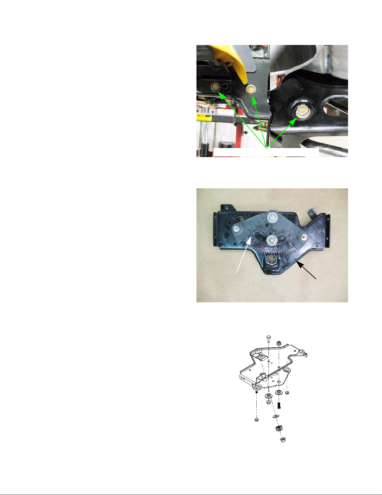
6d. Remove the nuts and bolts that hold th e front
edge of each fender to the frame outriggers
using a pair of 7/16” wrenches.
See Figure 4.32.
6e. Carefully lift the fender assembly off of the
tractor.
NOTE: On tractors equipped with a Kohler s ing le
cylinder engine, the front of the fender
mounts to the outrigger using a rubber bush
ing and steel spacer. See Figure 4.33.
Nut, bolt, and washer
Figure 4.32
Steel spacer
Rubber
bushing
Figure 4.33
48
Page 55

Screws that hold
the handle assembly
Figure 4.34
Steel reinforcement plate
Body Panels
NOTE: The handle assemblies can be removed from the
rear fenders using a 3/8” wrench, from b eneath the
fender.
NOTE: With the handle assembly removed, the steel rein-
forcement plate can be unbolted from the top side
of the fender using a 3/8” wrench.
See Figure 4.34.
See Figure 4.35.
Reinforcement plate
mounting screws
Figure 4.35
49
Page 56

LTX Tractors
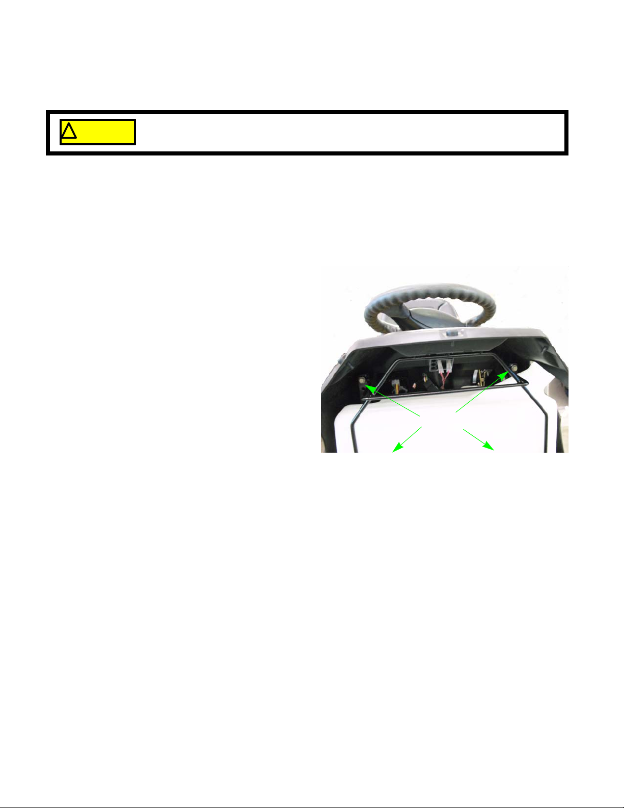
Dash Panel
The dash panel may be removed to provide easier
access to the cruise-control and drive system linkag e s, or
to
replace the dash or dash support brackets.
1. Remove the fenders.
2. Remove the steering wheel:
2a. Remove the cover from the center of the
steering wheel.
NOTE: The cover can be released by prying-in on
the lock-tabs on the under-side of the steer
ing wheel. See Figure 4.37.
See Figure 4.36.
Figure 4.36
-
2b. Remove the bolt that holds the steering wheel
to the steering shaft using a 1/2” wrench.
2c. Lift the steering wheel off of the shaft.
! CA UTION! CA UTION
The following steps involve working with gasoline. Gasoline is flammable, and steps should be
taken to avoid fire hazard;
• Work in a well-ventilated area.
• Allow the engine to cool fully before starting work on the tractor.
• Eliminate any sources of possible ignition from the work area, including but not limited to:
heat sources, open flame, potential sparks.
• Clean-up any spilled fuel quickly and properly, disposing of cleaning materials in a way that
will not produce a further fire hazard.
Figure 4.37
50
• Hold any drained fuel in an approved and safe container.
Page 57

Top tank bracket mounting screw
Figure 4.38
Body Panels
3. Remove the fuel tank.
3a. Drain the fuel tank to a level that will not allow
fuel to spill.
NOTE: The tank may be drained by mechanical syphon or
by disconnecting the fuel line from the fuel filter.
3b. Remove the two screws that hold the top of the
wire form fuel tank bracket to the dash support
brackets using a 3/8” wrench.
3c. Support the fuel tank.
See Figure 4.38.
Figure 4.39
3d. Remove the two screws that hold the bottom of
the wire form bracket to the dash support brack
ets using a 3/8” wrench.
3e. Lift the fuel tank and bracket out of the tractor.
See Figure 4.39.
NOTE: The fuel line may be lef t connected to the fuel t ank,
and the fuel tank supported next to the tractor in a
position that will not allow fuel to spill.
See Figure 4.40.
-
Figure 4.40
51
Page 58

LTX Tractors
4. Disconnect the harness plugs from the following
electrical devices under the dashboard:
See Figure 4.41.
• Hour meter
• Key switch
• RMC module
• PTO switch, if so equipped
5. Use a phillips head screwdriver to remove the throttle control grip. See Figure 4.42.
6. Carefully peel-off the throttle control label.
• Gentle application of heat will help loosen the
adhesive.
Hour meter
RMC Module
Key switch
PTO switch
Figure 4.41
Throttle grip
Throttle control
label
• Use wax paper to preserve the adhesive.
7. Remove the two Torx
TM
head screws that hold the
throttle control to the dash panel using a T-27 driver.
See Figure 4.43.
Figure 4.42
52
Figure 4.43
Page 59

Rod
Figure 4.44
Body Panels
8. If the tractor has a separate choke cable, disconnect
it from the engine.
9. Remove the locking clip that holds the cruise control /
parking brake rod to the engagement lever assembly.
See Figure 4.44.
10. Disengage the rod from the lever assembly.
NOTE: The rod is kept in slight tension by a light spring
that hooks between the frame and the step in the
middle of the rod.
See Figure 4.45.
Spring
Figure 4.45
Internal
mounting ear
Screw
Dash support
bracket
11. Remove the screws that hold the inside mounting
ears of the dash panel to the dash support brackets
using a 3/8” wrench.
See Figure 4.46.
Figure 4.46
53
Page 60

LTX Tractors
12. Remove the four screws that hold the base of the
dash panel to the frame using a T-40 driver and a 1/
2” wrench.
NOTE: On tractors equipped with electro nic powe r
• Remove the screw that holds the EPS motor
See Figure 4.47.
steering:
cover to the left side of the dash using a 3/8”
wrench.
See Figure 4.48.
Torx head screw
Hex-head cap screw
Figure 4.47
EPS motor
cover
• Pull the EPS motor cover off of the barbed fas-
tener.
13. Lift the dash panel off of the tractor.
See Figure 4.49.
14. Assembly notes:
• Assemble tractor by reversing the disassembly
process.
• Tighten fasteners to a torque of 20-22 in-lbs.
(2.25-2.50 N-m).
• Test all tractor controls and features before
returning the tractor to service.
Figure 4.48
54
Figure 4.49
Page 61

HYDRO. DRIVE AND BRAKE SYSTEM
CHAPTER 5: HYDRO. DRIVE AND BRAKE SYSTEM
About this chapter
The drive and brake systems for the Cub Cadet Series 1000 tractor are combined. Two reasons for this:
• The brake on the Series 1000 tractor is supplied with the transaxle. On hydrostatic-drive tractors, the
brake comes from Hydro-Gear.
• The brake pedal applies the brake and disengages the drive system. Both systems share common linkage.
The hydrostatic transaxle used in the Cub Cadet Series 1000 is a Hydro-Gear model 311-0510. LTX and SLTX transaxles are similar except that the SLTX transaxles have 4-lug wheel mount hubs in place of a double -D axle.
NOTE: A training video BLN-51763 covers this transa xle .
NOTE: The complete Hydro-Gear Service and Repair ma nual, BLN-51260 is included as an addendum to this
manual, with the permission of and thanks to Hydro-Gear.
If the tractor has drive system problems within the warranty period, the Cub Cadet service dealer has the following
responsibilities:
• Eliminate any external causes for drive system problems, before removing the transmission from the tractor.
• External problems would include, but are not limited to: belt, linkage, low fluid, or brake issues.
• Look for signs of over-use or abuse. Transaxles that fail because of over use or abuse are not warrantable. They are to be repaired or replaced at the customer’s expense.
• If the problem is internal, the transmission is to be removed, repaired, and reinstalled unless the cost of
repair exceeds 70% of the price of a new replacement transaxle.
• If Hydro-Gear transaxle is replaced under warranty, the original transaxle will be called-back for evaluation and vendor recovery.
• Warranty Claims will be denied, returned, or adjusted if the returned transaxle does not meet Cub Cadet’s
replacement criteria.
• If the dealer has questions regarding transaxle replacement, they should call Cub Cadet Service, using
the dealer only line, before proceeding.
55
Page 62

LTX Tractors
Externally repairable drive system problems
Most of the problems listed in this section will result in a customer complaint of low power or low ground speed,
sometimes accompanied by growling or similar noises from the transaxle. If the tractor is difficult to push, check the
brakes and the hydraulic bypass.
1. Engine performance:
1a. Find the specified engine RPM for the tractor (
3,375-3,525 RPM for the Cub Cadet Series
1000).
1b. Check the engine with a tachometer to con-
firm that it maintains the specified RPM under
normal load.
1c. Correct engine performance problems before
trying to diagnose drive system problems.
2. Check the tires: Confirm that the correct size tires
are on the tractor.
See Figure 5.1.
Smaller rear tires will yield lower ground speed.
Under-filled tires will put additional load on the drive
system.
• LTX 1040 Series has 20” x 8” rear tires.
• LTX 1050 Series has 20” x 10” rear tires.
• SLTX 1050 Series has 22” x 9.5” rear tires.
3. Check the hydro. bypass linkage: See Figure 5.2.
3a. If the tractor does not drive with as much
speed or power as normal:
• Confirm that the transmission release rod is
fully engaged (pushed-in).
• When the transmission release rod is fully
engaged, confirm that the bypass arm on the
side of the transaxle moves freely.
• If the bypass arm is not releasing fully, the variable displacement pump will cavitate, or pump
air. The air bubbles will produce a growling
noise as they go through the system.
3b. If the tractor is difficult to push:
Figure 5.1
bypass linkage
Figure 5.2
• Confirm that the Transmission Release Rod is
disengaged (pulled-out and hooked).
• Confirm that the Transmission Release Rod and spring are moving the bypass arm correctly. It takes
about 5 lbs. (2.3 Kg.) force to move the bypass arm fully into the release position.
• If the bypass linkage is working correctly, confirm that the brakes are releasing fully.
56
Page 63

HYDRO. DRIVE AND BRAKE SYSTEM
4. Check the brakes: See Figure 5.3.
4a. The brake linkage applies the brakes and dis-
engages the drive belt. Confirm that both parts
of the linkage are moving properly.
• When the brake pedal is released, the transmis-
sion drive belt should be under tension. It should
take about 3 lbs (1.36 Kg.) of force at the center of
the longest span of the belt to move the belt 1/2”
(1.3 cm) inward.
Brake
return spring
Travel stop
Brake arm
Figure 5.3
Belt tension
gauge
Actuator spring
• If the belt is not tensioning properly, the drive will
slip. Some belt noise may be present, but the
transmission itself will not make much noise.
• Accelerated belt wear, and the presence of black
belt residue, are cause to check the belt tensioner
linkage.
• If the brake is dragging, the transmission is likely to
make growling noises and run hot.
• The rotor may be discolored from heat.
4b. If the linkage is working properly , but the brake s
seem to be dragging, check the caliper.
See Figure 5.4.
• When the brakes are released, it should be possi-
ble to wiggle the brake rotor within the caliper.
• If the rotor is tight in the caliper, check the caliper
adjustment.
Check the operation of the caliper to confirm that it is
not stuck.
• When the brake pedal is released, the brake arm
on the caliper should fall completely back against
the stop.
Figure 5.4
57
Page 64

LTX Tractors
4c. Operator error: See Figure 5.5.
Left foot on clutch
/brake pedal
• If the customer complains of symptoms similar
to a brake / clutch linkage problem, yet no
mechanical problem is present, check the customer.
5. Check the drive belt. See Figure 5.6.
• In normal use, drive belts typically last for years
without problems.
• If the belt fails prematurely, identify and correct
the cause of the belt failure before returning the
tractor to service.
Right foot on
Reverse
pedal
Operator
error
Figure 5.5
5a. Look-up the part number for the belt, and con-
firm that the correct OEM belt is on the tractor.
5b. Check the belt routing.
5c. Check the brake/clutch linkage and belt ten-
sioning pulleys.
5d. Check for foreign objects jammed against the
belt.
5e. Check for missing or out-of-place belt guides. See the belt replacement section of this chapter.
5f. Check the engine crankshaft and transaxle input pulleys.
Confirm that the sheaves are not spread-out, causing a loose belt fit.
Figure 5.6
58
Page 65

HYDRO. DRIVE AND BRAKE SYSTEM
Travel limit pin
Drive control rod
Drive pedal latch plate
Drive pedal bracket
Figure 5.7
Lost motion link
Lost motion slot;
Neutral or Forward
Drive control rod
Lost motion link
6. Check the drive control linkage. See Figure 5.7.
6a. The travel limit pin fits into the curved slot in the
drive pedal latch plate. The pedal bracket
should have enough travel for the pin to hit both
ends of the curved slot when the pedal is
moved through the full range of its travel.
6b. Some lost motion is built into the linkage so that
there is a “dead” range as the pedal moves
from neutral to reverse.
• This dead spot allows the reverse safety switch to
act before the tractor actually begins to move
backward.
See Figure 5.8.
Connector pin
Lost motion slot;
Reverse
Pedal mounting
bracket
Plastic bushing
Connector
pin
Figure 5.8
• It is normal to have 1-1/8” play at the Forward
pedal or 1” play at the Reverse pedal in this dead
range.
6c. The most likely causes for additional lost motion
that would effect the ground speed of tractor
are:
See Figure 5.9.
• The drive pedal itself being loose on the bracket.
• Worn plastic bushings between the drive pedal
bracket and the brake cross-shaft.
Figure 5.9
59
Page 66

LTX Tractors
6d. If the tractor makes drive noise or creeps
while the pedal is in neutral, but seems to
have lost speed in just one direction (forward
or reverse):
• The rod connecting the pedal bracket to the
arm on the transaxle may be bent, changing its
effective length. See Figure 5.10.
• The transaxle neutral control may be out of
adjustment. See the Neutral control adjustment
section of this chapter.
Drive control rod
Figure 5.10
7. Check the fluid:
• Unless the fluid gets contaminated, it should
last for many years with no fluid service.
• Check the level and condition of the fluid: It
should be no more than 1-1/4” (3.175 cm) down
from the top of the casting. The fluid level is
generally near the bottom of the threads in the
plug hole.
• Check at the socket-head plug on the casting,
NOT the plastic expansion tank. Remove the
plug using a 1/4” allen wrench.
See Figure 5.11.
• The transaxle should contain 20W-50 motor oil
having a minimum API classification of SL.
• If there is any reason to suspect that the fluid is contaminated, replace the fluid and monitor performance.
A second fluid change after a brief period of operation may be necessary to remove all contaminants.
• If the fluid is low, there is probably a leak that needs to be found and repaired.
• If the fluid is too full, it will drain into the catch tank
Expansion
tank
Figure 5.11
Fill port
60
Page 67

Torque bracket mounting points
HYDRO. DRIVE AND BRAKE SYSTEM
8. Transaxle mounting:
8a. The primary symptoms of a transaxle that is
loose in the frame are that it will lose drive or
throw-off the drive belt in reverse.
8b. Check the torque bracket and the axle mount-
ing points at the frame. See Figure 5.12.
9. Eliminate heat factors
Torque
bracket
Figure 5.12
Indications that a transaxle is not warrantable
Anything that would indicate misuse, abuse, neglect, accident, improper maintenance, alteration, vandalism,
theft, fire, water or damage because of other peril or natural disaster will render the transaxle non-warrantable even
though it is within the normal warranty per iod .
• As hydrostatic transaxles wear, they will begin to
lose drive power when they get hot.
• Heat is the enemy of transaxle performance and
longevity.
• If the cooling fan is damaged, replace it.
• Clean any mud and debris from the transaxle so
that it can shed heat properly.
• DO NOT clean the transaxle (or any part of the
tractor) with a pressure washer.
• Do not direct hose water at line pressure at the
transaxle or any bearings on the tractor.
NOTE: It is possible to inject water past seals, contaminat-
ing fluid and ruining bearings.
Typical indicators of a void warranty would be:
• The normal warranty is for 3 years or 120 hours, whichever comes first. Beyond 120 hours of use, the
tractor is out of warranty
• Abnormally high wear indicators for the age of the trac tor (usually consistent with high h ours of usage). As
an example, if the tires are completely worn-out on a tractor that is 6-months old, it is reasonable to think
it has been used pretty heavily even if the hour meter has been unplugged.
• Bent axle, broken housing, or other obvious signs of impact damage
• Contaminated fluid or low fluid
• Damage to the cooling fan
• Enough dirt or debris on the transaxle to prevent the it from cooling properly
• Indication that the tractor has been over-loaded.
61
Page 68

LTX Tractors
Brake adjustment
1. Test the operation of the brakes
1a. Disengage the transmission release rod by
pulling it out and hooking it.
1b. Set the parking brake by depressing the
brake/clutch pedal and pushing-down on the
parking brake/cruise control lever.
See Figure 5.13.
1c. Attempt to push the tractor. If it can be pushed
by hand without skidding a rear wheel, check
and adjust the brakes.
1d. Release the parking brake.
1e. Attempt to push the tractor again. If it cannot
be pushed with reasonable effort, check and
adjust the brakes and the hydro bypass (con
trolled by the transmission release rod).
2. Visually inspect the linkage to confirm that it functions properly. See Figure 5.14.
• Beneath the floor panel, on the right side of the
tractor there are two semi-circular latch plates.
• The outer latch plate rotates with the drive con-
trol pedals. The inner latch plate rotates with
the clutch/brake pedal.
2a. With the clutch/brake pedal fully released:
• The travel limit pin should be resting against the
front of the curved slot. See Figure 5.14.
-
Travel limit pin
Figure 5.13
Clutch/brake latch plate:
fully released position
Figure 5.14
• The rod that connects the clutch/brake latch
plate to the heavy brake actuator spring should
be slack. See Figure 5.15.
• The light brake pull-off spring should be holding
the brake arm back against the stop.
62
Brake actuator rod
Brake actuator spring
Pull-off
spring
Figure 5.15
Page 69

HYDRO. DRIVE AND BRAKE SYSTEM
2b. Check the gap between the brake rotor and the
brake pads.
• There is a fixed pad in the transaxle housing.
• There is a moving pad in the brake caliper.
• Wiggle the brake rotor slightly, and attempt to
insert a 0.015” (0.38mm) feeler gauge between the
rotor and either pad.
Brake
yoke
Figure 5.16
Brake
rotor
2c. Adjust the gap, if necessary, so that the feeler
gauge slips between the pad and the rotor with
light pressure.
• If adjustment is necessary , remove and discard the
cotter pin that locks the adjusting nut.
• Turn the nut to adjust the gap.
• Apply and release the brake pedal, then re-check
the gap.
• If the gap is consistent, install a new cotter pin to
secure the adjustment nut.
2d. If the brake seems to be sticking, or the rotor is
discolored from dragging, remove the brake
yoke for repair or replacement.
2e. Confirm that the drive belt is under tension
when the brake is released.
2f. Set the brake. The drive belt should be slack.
2g. Re-test the operation of the brakes before
returning the tractor to service.
NOTE: The hydrostatic transaxle creates it’s own braking
force from the hydraulic pressure in the hydraulic
motor. The br ake is used more as a parking brake
than a service brake. Properly adjusted brakes
generally show little wear over the life of the trac
tor.
See Figure 5.16.
-
63
Page 70

LTX Tractors
Neutral control adjustment
NOTE: Neutral control rarely goes out of adjustment on its own. If it needs adjustment, check for damaged
linkage or signs of tampering.
! CA UTION! CA UTION
1. Loosen the wheel bolt or lug nuts on the right rear
wheel of the tractor.
2. Lift and safely support the rear of the tractor.
3. Remove the right rear wheel:
• LTX tractor drive wheels fit on a “Double-D”
axle, and can be removed using a 1/2” wrench.
• SLTX tractor drive wheels are hub mounted.
Remove the lug nuts using a 3/4” wrench.
4. bypass the seat safety switch. See Figure 5.17.
4a. Remove the seat from the tractor.
4b. Disconnect the seat safety switch.
NOTE: This procedure is described in Chapter 4:
The tractor engine and drive system must be operated to complete this procedure. Confirm
that no hazards will be incurred by running the engine or operating the drive system:
• Work in a well vented area to prevent carbon monoxide poisoning or asphyxiation.
• Be careful to avoid contact with hot parts or moving parts.
Body Panels.
Seat safety switch
Figure 5.17
5. Confirm that the linkage is in the neutral position:
The roller on the control arm must be centered in
the “elbow” of the control cam.
• If the roller is not centered in the elbow of the
control cam, identify and correct the problem
before proceeding.
64
See Figure 5.18.
Cam
Roller
Figure 5.18
Page 71

HYDRO. DRIVE AND BRAKE SYSTEM
6. Loosen the socket head cap screw that locks the
adjusting puck using a 1/4” allen wrench.
7. Have a 1-1/8” wrench handy, or size an adjustable
wrench to fit the adjusting puck.
See Figure 5.19.
8. Start the engine and advance throttle to maximum
RPM.
9. Set the adjusting puck so that neither wheel rotates.
The brake rotor should also be stationary.
10. Lock the adjusting puck, then confirm that the wheels
and brake rotor are still motionless.
11. Turn the engine off.
12. Reinstall the seat, reconnecting the seat switch.
13. Reinstall the rear wheel:
Double-D axle
13a. Lubricate the axle with anti-seize compound
before positioning the wheel on LTX models.
Figure 5.19
13b. Apply thread locking compound such as Loctite
TM
242
(blue) to the threads of the wheel bolt.
13c. Install the bolt and belleville washer so that the
inside diameter contact area of the washer is
against the bolt head and the outside diameter
contact area is against the wheel.
Hub
13d. Position the wheel on the hub and secure it with
four lugs.
14. Lower the tractor to the ground.
14a. Tighten the bolt to a torque of 12-15 ft-lbs. (16-
20 N-m).
14b. Tighten the lugs on the SLTX tractors to a
torque of 30-42 ft-lbs. (41-57 N-m).
15. Test the drive system and all safety features before
returning the unit to service.
65
Page 72

LTX Tractors
Linkage: pedal shaft
Description: The Clutch/brake pedal and the drive control
pedal operate on two concentric shafts.
• The clutch/brake shaft runs the full width of the
tractor.
• The drive control shaft is tubular, and pivots on
the clutch/brake shaft.
• Each shaft has a toothed latch plate. The latch
plates are next to each other.
• The cruise control/park brake lever operates a
common pawl that engages the latch plate of
whichever pedal is applied. See Figure 5.20.
• A travel limit pin passes through curved slots in
both of the latch plates. The pin is blocked into
place by the fenders. See Figure 5.21.
Cruise / park
pawl
Clutch/brake
latch plate
Drive (cruise control) latch plate
Figure 5.20
66
Travel limit pin
Figure 5.21
Page 73

Pedal shaft assembly removal
Clutch/brake shaft Rod
Figure 5.22
Travel limit pin
HYDRO. DRIVE AND BRAKE SYSTEM
NOTE: Confirm that the parking brake is released before
starting work.
1. Remove the mowing deck.
2. Remove the fenders, as described in the body p anels
chapter of this manual.
3. Disconnect the rod that joins the arm at the left side
of the brake/clutch shaft to the drive belt tensioner
pulley bracket.
• Remove and discard the cotter pin to disconnect
the rod.
4. Remove the locking clip that holds the travel limit pin
in place.
See Figure 5.22.
Clutch/brake pedal
return spring
5. Withdraw the travel limit pin. See Figure 5.23.
Latch plates
Figure 5.23
6. Unhook the clutch/brake pedal return spring.
See Figure 5.24.
Hooks to clutch/brake
latch plate
Figure 5.24
Hooks to frame
67
Page 74

LTX Tractors
7. Remove and discard the push cap that holds the
drive control pedal shaft onto the clut ch/brake shaf t.
See Figure 5.25.
8. Loosen the bolt that holds the left pedal shaft support strap using a 1/2” wrench. See Figure 5.26.
9. Remove the bolt that holds the right pedal shaft support strap using a 1/2” wrench.
NOTE: This will allow the pedal shaft assembly to
hang-down slightly on the right side of the
tractor.
Tie-rod
separator
Figure 5.25
Left pedal shaft support strap
Figure 5.26
Push cap
10. Disconnect the drive control rod from the drive
pedal latch plate.
• Remove and discard the cotter pin.
• Unhook the drive control rod.
68
See Figure 5.27.
Drive control
rod
Drive pedal
latch plate
Figure 5.27
Page 75

Drive control
pedal shaft
Figure 5.28
HYDRO. DRIVE AND BRAKE SYSTEM
1 1. Allow the drive pedal shaft to rotate down, then pull it
off of the pedal shaft assembly.
See Figure 5.28.
Clutch/brake
latch plate
Figure 5.29
Brake rod
Flat washer
12. Disconnect the brake rod from the clutch/brake latch
plate.
See Figure 5.29.
• Remove the cotter pin and flat washer to discon-
nect the brake rod. Discard the cotter pin.
• Unhook the brake rod from the clutch/brake latch
plate.
13. Remove the left side pedal shaft support strap, and
lower the pedal shaft assembly out of the tractor.
See Figure 5.30.
Figure 5.30
69
Page 76

LTX Tractors
NOTE: The pedal shaft support straps are two dif-
ferent sizes. The smaller strap holds-up the
left (brake pedal) end of the pedal shaft
assembly. The larger strap holds-up the right
(drive control pedal) end of the pedal shaft
assembly.
14. Inspect the pedal shaft components individually.
Replace any parts that are worn or damaged.
See Figure 5.32.
See Figure 5.31.
Left side strap Right side strap
Figure 5.31
Clutch/brake pedal shaft Push cap
• The plastic bushings that fit between the two
pedal shafts should be replaced any time they
are removed. Lubricate them with a dry PTFE
or graphite-based lubricant on assembly. NOT
grease.
• Replace the push cap and all removed cotter
pins with new parts.
15. Install the pedal shaft assembly by reversing the
steps used to remove it, then install the fe nders.
15a.Lubricate the points where the pedal shaft s
meet the frame with a good quality lithiumbased grease.
See Figure 5.33.
Drive pedal shaft Pedal shaft
support strap
Bushings
Figure 5.32
70
Figure 5.33
Page 77

Figure 5.34
HYDRO. DRIVE AND BRAKE SYSTEM
NOTE: Leaving the drive control pedal shaft loose until
after the brake rod is secured will make it easier .
15b. Position the drive control shaft and bushings,
fasten the drive control rod to it, then drive the
push cap on.
15c. Tighten the pedal shaft support strap bolts to a
torque of 12-15 ft-lbs. (16-20 N-m).
15d. Attach the belt tensioner pulley rod.
16. Test the drive system and all safety features before
returning the tractor to service.
See Figure 5.34.
71
Page 78

LTX Tractors
Belt control; tensioner and idler pulleys
NOTE: The V-idler pulleys can be removed from
below using a 1/2” wrench, with no disas
se m b ly be y o nd rem o v ing t h e cutt i n g deck .
See Figure 5.35.
NOTE: Confirm that the parking brake is released
before starting work.
1. Remove the mowing deck.
2. Remove the fenders by following the steps
described in Chapter 4: Body Panels.
V-sheave
pulleys
-
Figure 5.35
3. Disconnect the rod that joins the arm at the le ft side
of the clutch/brake shaft to the drive belt tensioner
pulley bracket.
• Remove and discard the cotter pin to discon-
nect the rod.
4. Disconnect the extension spring that pulls on the
bracket to tension the drive belt.
See Figure 5.36.
See Figure 5.37.
Clutch/brake shaft Rod Bracket
Figure 5.36
Extension spring
72
Mounting points
Figure 5.37
Page 79

Figure 5.38
Remove this bolt.
Nut is above frame
HYDRO. DRIVE AND BRAKE SYSTEM
5. Note the belt routing, then slip the drive belt off of the
two pulleys on the tensioning bracket.
6. Remove the nut and bolt that hold the belt tensioner
pulley bracket to the frame using a pair of 9/16”
wrenches.
7. Maneuver the belt tensioner bracket assembly to
clear the belt, and remove it from the tractor.
See Figure 5.39.
See Figure 5.38.
Figure 5.39
Bracket pivot point
Figure 5.40
NOTE: The bracket assembly pivots on the bolt that
passes through the fixed, flat-sheave idler pulley.
8. On the bench, the flat-sheave idler pulley, and the
spacers used to position it can be lifted off of the pul
ley bracket. See Figure 5.40.
-
73
Page 80

LTX Tractors
NOTE: When installed, the head of the bolt that
holds the bracket assembly to the tractor
rests against the shouldered side of the flat
sheave idler pulley.
See Figure 5.41.
Shoulder height
Figure 5.41
• When installed, the spacers fit against the flat
side of the flat sheave idler pulley.
See Figure 5.42.
9. The V-sheave tensioner pulley can be un-bolted
from the bracket using a 1/2” wrench.
10. The rod that connects the bracket to the clutch/
brake pedal shaft can be maneuvered to come out
of its slot in the bracket.
11. Assemble and install the belt tensioner pulley by
reversing the steps used to remove and disassem
ble it.
See Figure 5.43.
Flat sheave pulley
Figure 5.42
-
Flat surface
Hex bushing
Shoulder bushing
Bolt
• Lubricate the pivot point with a good quality lith-
ium-base grease.
12. Reinstall the fenders.
13. Test the drive system and all safety features before
returning the tractor to service.
74
Figure 5.43
Page 81

Drive belt replacement
HYDRO. DRIVE AND BRAKE SYSTEM
! CA UTION! CA UTION
The battery will be removed in this procedure. Review the Operator’s Manual and Chapter 7:
Electrical System for important safety information abou t ha nd lin g ba tte r ies be fo re proce e din g.
1. Remove the mowing deck.
2. Set the park brake to release belt tension.
3. Remove the battery and battery tray by following the
procedures described in Chapter 4: Body Panels.
See Figure 5.44.
Figure 5.44
Fan nut
4. Remove drive belt from the transaxle pulley.
See Figure 5.45.
Figure 5.45
4a. Remove the nut using a 3/4” wrench. An impact
wrench with a socket will be most effective.
4b. Lift-off the cooling fan.
75
Page 82

LTX Tractors
4c. Remove the pulley. The belt will clear the belt
keepers on top of the transaxle as the pulley
comes up.
NOTE: Correct orientation of input pulley:
See Figure 5.47.
See Figure 5.46.
Figure 5.46
Top of hydro. pulley
• Tall shoulder goes up.
• Short shoulder with snap-ring stop goes down.
5. Lift and safely support the tractor. See Figure 5.48.
Bottom of hydro. pulley
Figure 5.47
76
Figure 5.48
Page 83

Belt
Belt route
HYDRO. DRIVE AND BRAKE SYSTEM
6. Work the belt out of the two pulleys on the belt tensioner bracket. See Figure 5.49.
Figure 5.49
Fixed idler
Belt keeper pin
Figure 5.50
7. Remove the single, fixe d idler from the frame of the
tractor using a 1/2” wrench.
8. Remove the belt keeper near the engine pulley or
electric PTO clutch, using a 1/2” wrench.
8a. With manual PTO, a single bolt holds the belt
keeper to the frame, to the left side of the
engine.
See Figure 5.51.
See Figure 5.50.
Bolt
Belt keeper
Shoulder
fits through
hole in frame
Figure 5.51
77
Page 84

LTX Tractors
8b. With electric PTO, there are two fasteners:
See Figure 5.52.
8c. One bolt holds the belt keeper to the frame, to
the left side of the engine.
8d. A nut holds the belt keeper to the right-side
frame channel.
NOTE: The electric PTO belt keeper incorporates
an anti-rotation bracket for the PTO clutch.
9. Lower the engine pulley to remove the belt; manual
PTO.
Nut
Belt keeper
Bolt
Figure 5.52
9a. Remove the bolt that holds the engine pulley
to the crankshaft using a 5/8” wrench.
9b. Slide the pulley off of the engine crankshaft.
The belt will clear the belt keepers as the pul
ley comes down. See Figure 5.53.
9c. Remove the belt.
10. Lower the engine pulley to remove the belt; electric
PTO.
10a.Disconnect the PTO clutch electrical plug from
the harness.
See Figure 5.54.
-
Figure 5.53
Wire harness
PTO clutch plug
78
Figure 5.54
Page 85

HYDRO. DRIVE AND BRAKE SYSTEM
10b. Remove the bolt that holds the PTO clutch to
the engine crankshaft using a 5/8” wrench.
Figure 5.55.
NOTE: An impact wrench and socket will be most effec-
tive. Otherwise it may be necessary to block the
ring-gear to prevent the crankshaft from turning .
See
Crankshaft bolt PTO Clutch
Figure 5.55
Washers (2)
PTO clutch
Crankshaft bolt
! CAUTION! CAUTION
10c. Carefully lower the PTO clutch and any associ-
ated hardware. See Figure 5.56.
The PTO clutch is heavy, and it
may fall as the bolt is removed.
Figure 5.56
Belt keepers
Figure 5.57
10d. Slide the pulley off of the engine crankshaft.
The belt will clear the belt keepers as the pulley
comes down.
10e. Remove the belt.
See Figure 5.57.
79
Page 86

LTX Tractors
NOTE: The flat edge of the crankshaft pulley faces
the electric PTO clutch. The end with the
inside diameter chamfered goes against the
fillet near the base of the crankshaft.
See Figure 5.58.
11. If the drive belt failed prematurely, identify and correct the cause of the failure before installing a new
belt.
12. Install the new belt by reversing the steps used to
remove it.
Belt installation notes:
• Install only a correct OEM belt. Incorrect belts
may cause problems that effect the performance and/or safety of the tractor.
• Apply a small amount of anti-seize compound
to the engine crankshaft before installing the
crankshaft pulley.
• Apply a small amount of thread locking com-
pound such as Loctite 271
TM
(red) to the
threads of the crankshaft bolt.
• Tighten the bolt to a torque of 36-50 ft-lbs. (50-
68 N-m).
• The belt is routed to the left of the steering
shaft, and the fore-most keeper pin goes
between the runs of the belt. See Figure 5.59.
Top of
crankshaft pulley
Bottom of
crankshaft pulley
Figure 5.58
Belt keeper pin
Steering shaft
Belt
• Correct routing. See Figure 5.60.
• Tighten the nut that holds the fan and pulley to
the input shaft to a torque of 30-43 ft-lbs (41-58
N-m).
13. Thoroughly test the operation of the drive system
and all safety features before returning the tra ctor to
service.
Looking forward from under the tractor
Figure 5.59
Front Back
Figure 5.60
80
Page 87

HYDRO. DRIVE AND BRAKE SYSTEM
Changing transaxle hydraulic fluid
NOTE: The Hydro-Gear hydrostatic transaxle used in the Cub Cadet 1000 Series tractors typically lasts for
many years of homeowner use without fluid maintenance. The primary reason to change the fluid
would be contamination.
NOTE: The ambient temperature should be above 60 deg. f. (15.5 deg. C.) to allow the fluid to drain and fill in
a reasonable amount of time.
! CA UTION! CA UTION
The battery will be removed in this procedure. Review the Operator’s Manual and Chapter 7:
Electrical System for important safety information abou t ha nd lin g ba tte r ies be fo re proce e din g.
1. Allow the drive system to cool before starting work on
the tractor.
2. Remove the battery and battery tray by following the
procedures described in Chapter 4: Body Panels.
See Figure 5.61.
3. Locate the drain plug near the bottom of the differential housing of the transaxle.
4. Clean the area around the drain plug, and place a
drain pan of at least 1 gallon (4 liters) capacity under
the transaxle.
5. Remove the plug using a 1/4” allen wrench, and allo w
the fluid to drain.
Figure 5.61
NOTE: If the transaxle does not have a drain plug:
• The fluid may be siphoned out or the transaxle
may be removed from the tractor and drained
through the fill port.
Catch tank vent fill port
Figure 5.62
6. Locate the fill port. It is the socket-head cap plug on
top of the transaxle casting. It is not the black cap on
top of the plastic catch tank.
7. Clean the area around the fill port.
8. Remove the plug using a 1/4” allen wrench.
See Figure 5.62.
NOTE: If the transaxle is draining slowly, this will allow
more air to enter the housing, speeding up the
draining process.
9. After the transaxle has drained completely, reinstall
the drain plug.
81
Page 88

LTX Tractors
10. Fill the transaxle with 77 to 80 fluid ounces (2.3 to
2.4 L) of 20W-50 engine oil that has a minimum API
classification of SL, and a minimum rating of 55
SUS @ 210 deg. F. (99 deg. C).
11. Purge the transaxle. See Figure 5.63.
11a. Open the bypass valve.
11b. Start the engine, and run it at low RPMs.
11c. Slowly cycle the drive pedal 6 times from full
forward to full reverse, taking about 10 sec
onds to complete a stroke.
11d. Close the bypass valve.
Tr a ns m i s s io n r e lea s e r o d:
operates bypass valve
(shown released)
-
11e. Slowly cycle the drive pedal 6 times from full
forward to full reverse, taking about 10 sec
onds to complete a stroke.
11f. Turn the engine off.
11g. Check the fluid level, and add fluid if neces-
sary to bring the level within 1-1/4” of the top
of the casting.
11h. Close the bypass valve. See Figure 5.64.
11i. Start the engine, and run it at low RPMs.
11j. Slowly cycle the drive pedal 6 times from full
forward to full reverse, taking about 10 sec
onds to complete a stroke.
11k. Close the bypass valve.
11l. Slowly cycle the drive pedal 6 times from full
forward to full reverse, taking about 10 sec
onds to complete a stroke.
11m.Turn the engine off.
11n. Check the fluid level, and add fluid if necessary to bring the level within 1-1/4” of the top of the casting.
-
Transmission release rod
operates bypass valve
-
(shown engaged)
-
Figure 5.63
Figure 5.64
12. Test drive the tractor. If it does not operate at normal speed with no unusual transmission noise, repeat the
purging process.
82
Page 89

Brakes
HYDRO. DRIVE AND BRAKE SYSTEM
Brake arm
Return spring
Brake yoke
Castle nut
Cotter pin
Actuator spring hooks here
NOTE: The brakes may be repaired in the tractor, using
procedures shown on the bench.
1. The brake yoke is located on the right side of the transaxle. See Figure 5.65.
• The heavy actuator spring connects to the top hole
on the brake arm.
• The light return spring draws the brake arm to the
OFF position.
• Remove the cotter pin and loosen or tighten the
castle nut to adjust the brakes. Use a 9/16” wr ench
to set a 0.015” (0.381mm) gap.
Figure 5.65
2. There are two main reasons to remove the caliper: to
replace the pads, or to free stuck parts.
3. Loosen both brake yoke bolts using a 3/8” wrench.
See Figure 5.66.
Figure 5.66
Brake rotor
Brake yoke
Installed r-t-n spring
fits into groove in spacer
Figure 5.67
4. Slip the return-to-neutral (r-t-n) spring off of the
spacer on the front bolt.
5. The yoke and outer pad will separate from the transaxle. See Figure 5.67.
Short r-t-n
spring
Grooved spacer
83
Page 90

LTX Tractors
6. Inside the brake yoke;
• A steel backing plate fits between the friction
pad and the actuator pins.
• The pins fit into holes in the brake yoke housing.
• The brake arm acts as a cam, pushing the pins
when it rotates.
• A small compression spring pushes the cam
arm away from the pins, helping to release the
brake.
7. With the brake yoke removed, the brake rotor floats
on a splined brake shaft.
See Figure 5.69.
• The bypass linkage must be removed to take
the rotor off.
• The flat side goes in, the collar faces out.
Brake arm
Spring
Brake yoke
Actuator pins (2)
Backing plate
Friction pad
Figure 5.68
Brake pad
Brake rotor
bypass
arm
• A second brake pad fits into a recess behind
the rotor.
8. Assembly notes:
• If any lubricant is used on the pins or between
the brake shaft and the rotor, apply it VERY
sparingly.
• Apply a small amount of thread locking com-
pound such as Loctite 242
TM(blue) to the
threads of the brake yoke bolts.
• Tighten the brake yoke bolts to a torque of 80 to 120 in-lbs. (9 to 14 N-m).
9. Adjust and test the brakes after any work on brake system.
Figure 5.69
84
Page 91

Transaxle removal and replacement
HYDRO. DRIVE AND BRAKE SYSTEM
! CA UTION! CA UTION
The battery will be removed in this procedure. Review the Operator’s Manual and Chapter 7:
Electrical System for important safety information abou t ha nd lin g ba tte r ies be fo re proce e din g.
1. Remove the mowing deck by following the procedures described in Chapter 8: Cutting Decks and Lift
Shaft.
2. Set the park brake to release belt tension.
3. Remove the battery and battery tray, as described in
the body work chapter of this manual.
See Figure 5.70.
Figure 5.70
Fan Nut
Figure 5.71
4. Remove drive belt from the transaxle pulley.
See Figure 5.71.
4a. Remove the nut using a 3/4” wrench. An impact
wrench with a socket will be most effective.
4b. Lift the cooling fan off.
85
Page 92

LTX Tractors
4c. Remove the pulley. The belt will clear the belt
keepers on top of the transaxle as the pulley
comes up.
5. Loosen, but do not remove the wheel bolts (DoubleD axles) or lug nuts, using a 1/2” wrench or a 3/4”
wrench, respectively .
6. Unhook the large return-to-neutral spring from the
back of the tractor frame. Leave the other end con
nected to the top of the return-to-neutral cam.
See Figure 5.73.
See Figure 5.72.
Figure 5.72
-
NOTE: There is a second, shorter return-to-neutral
spring that stretches between the cam and
the grooved spacer on the front mounting
bolt of the brake yoke.
7. Release the parking brake.
8. Lift, and safely support the tractor. The rear of the
tractor should be high enough to allow the tran saxle
to pass under it.
9. Remove the rear wheels. If the tractor has Double-D
axles, remove the wheel spacers too.
See Figure 5.74.
Large r-t-n spring
Figure 5.73
86
Figure 5.74
Page 93

HYDRO. DRIVE AND BRAKE SYSTEM
Reverse safety switch
(yellow wire)
Trunnion arm
(green wire)
Figure 5.75
Drive control rod Trunnion arm
10. Disconnect the wires from the reverse safety switch.
See Figure 5.75.
10a. Unplug the yellow w/black trace wire.
10b. Remove the bolt that holds the green ground
wire using a 3/8” wrench.
11. Disconnect the drive control rod from the trunnion
arm of the hydro.
See Figure 5.76.
Spring
Spring
Bypass rod
Cotter
pin
Figure 5.76
Figure 5.77
bypass arm
12. Disconnect the spring at the end of the bypass rod
rod from the bypass arm on the transaxle.
5.77.
NOTE: The closed end of the spring hooks downward into
the rod.
13. Support the transaxle so that it can be lowered out of
the tractor in a controlled fashion.
See Figure
87
Page 94

LTX Tractors
14. Remove the torque bracket bolts using a 1/2”
wrench.
15. Take the nuts off of the T-bolts that hold the transaxle to the frame using a 1/2” wrench.
See Figure 5.79.
See Figure 5.78.
Bolts
Torque bracket
Figure 5.78
NOTE: At this point, the brake actuator spring is still
attached to the brake rod from the pedal
shaft, and the brake arm on the transaxle.
16. Carefully lower the transaxle out of the tractor.
See Figure 5.80.
Figure 5.79
88
Figure 5.80
Page 95

Large r-t-n spring
Brake actuator spring
Figure 5.81
Round hole Oblong hole
HYDRO. DRIVE AND BRAKE SYSTEM
17. Move the transaxle forwa r d to make some slack in
the brake linkage. Use the slack to unhook the brake
spring from the brake arm.
18. Carefully lift the transaxle onto a workbench for drain ing or disassembly as needed.
19. On the bench;
Figure 5.82
Reverse
safety switch Trunn ion arm
“T” slot
19a. The top of the reverse safety switch is held
against the trunnion arm by the post on the
drive control rod.
NOTE: The post passes through a roun d hole in the switch
plate and an oblong hole in the trunnion arm.
19b. The bottom of the reverse safety switch fits into
a “T” slot in the trunnion arm.
See Figure 5.82.
See Figure 5.83.
Figure 5.83
89
Page 96

LTX Tractors
19c. The large return-to-neutral spring can be
unhooked from the return-to-neutral cam.
See Figure 5.84.
Large r-t-n spring
19d.Remove the belt keeper from the top of the
transaxle using a phillips head screwdriver.
See Figure 5.85.
20. Installation notes:
20a.After repairs are done, and the transmission is
re-filled with fluid, it may be “bench purged” if
the technician has a way to drive the input
shaft using a 1/2” drill motor.
20b.Check adjustment of the brake before installing
the transaxle.
20c. Position the large return-to-neutral spring on
the return-to-neutral cam before lifting the tran
saxle back into the tractor.
20d.Connect both ends of the brake actuator spring
before lifting the transaxle back into the tractor.
Small r-t-n spring
Figure 5.84
Belt
keeper
Screw
-
Figure 5.85
r-t-n cam
20e. Coat the Double-D axle shaft with a high quality grease or anti seize compound before installing the
wheels.
20f. The spring in the bypass linkage hooks downward into the transmission release rod.
20g.Tighten fasteners according to the accompanying torque table.
20h.Fully purge the drive system before operating the tractor.
20i. Operate and test the drive system, brake system, and all safety features before returning the tractor to
service.
90
Page 97

HYDRO. DRIVE AND BRAKE SYSTEM
Drive System Torque Specs.
Fastener Torque in-lb. Torque N-m
Seat bolt 150-180 17-20
Lug nut 350-500 41-57
Wheel bolt 160-190 18-22
Fan/pulley nut 360-520 41-59
Tq. bracket bolt 150-180 17-20
Axle T-bolt nuts 150-180 17-20
Brake yoke bolts 80-120 9-14
Pedal shaft straps 150-180 17-20
Belt keeper nut /bolt 150-180 17-20
Idler pulley bolt 150-180 17-20
Tensioner bracket 150-180 17-20
91
Page 98

LTX Tractors
92
Page 99

CVT DRIVE AND BRAKE SYSTEM
CHAPTER 6: CVT DRIVE AND BRAKE SYSTEM
About this chapter
The drive and brake systems for the Cub Cadet Series 1000 tractor are combined. Two reasons for this:
• The brake on the Series 1000 tractor is supplied with the transaxle.
• The brake pedal applies the brake and disengages the drive system. Both systems share common linkage.
The transaxle used in the Cub Cadet Series 1000 is a relatively simple gearbox containing forward, neutral, and
reverse gears. The variation in speed is all handled by the variable speed pulley system that drives the transaxle.
If the tractor has drive system problems within the warranty period, the servicing Cub Cadet dealer has the fol-
lowing responsibilities:
• Eliminate any external causes for drive system problems before removing the transmission from the tractor.
• External problems would include, but are not limited to: belt, linkage, or brake issues.
• Look for signs of over-use or abuse. Transaxles that fail because of over use or abuse are not warrantable. They are to be repaired or replaced at the customer’s expense.
• If the problem is internal, the transmission is to be replaced under the like-kind exchange policy.
• If a transaxle is replaced under warranty, the original transaxle may be called-back for evaluation by MTD
Vendor Recovery Dept.
• Warranty Claims will be denied, returned, or adjusted if the returned transaxle does not meet Cub Cadet’s
replacement criteria.
• Dealers are encouraged to open transaxles for inspection, allowing them to identify a problem within the
transaxle.
• Beyond warranty, dealers are free to repair transmissions at customer expense.
• If the dealer has questions regarding transaxle replacement, they should call Cub Cadet Ser vice using the
dealer only line before proceeding.
About the variable speed drive system.
There are two drive belts in the system. A long drive belt transfers power from the engine crankshaft to the lower
sheave of the variable-speed pulley. A shorter belt fits in the upper sheave of the variable speed pulley; transferring
power from there to the input pulley on the transaxle.
• The drive control pedal tensions the front drive belt.
• The center partition of the variable speed pulley sep arates the lower (front) belt from the upper (rear) belt.
• As the front belt is tensioned, it is drawn deeper into its sheave. The effective circumference of the driven
pulley shrinks.
• As the front belt is drawn deeper into its sheave, the center partition is forced upward, making the upper
shave narrower.
• As the upper sheave pinches-down on the rear drive belt, the belt is forced outward in the sheave. The
effective circumference of the pulley driving the rear belt grows.
• As the upper and lower sheaves change size, the drive ratio shifts increasing the speed of the rear belt.
• As the sheave that drives the rear belt changes size, the be lt m ust be ke pt un der con stant tension. A tension idler pulley accomplishes this task.
• The clutch/brake pedal automatically de-tensions the front belt when it is applied.
93
Page 100

LTX Tractors
Externally repairable drive system problems:
Most of the problems listed in this section will result in a
customer complaint of low power or low ground speed. If
the tractor is difficult to push, check the brakes.
1. Engine performance:
• If the engine does not turn at the specified
RPM, the tractor will not travel at its designed
speed. See Figure 6.1.
• If the engine does not produce the specified
amount of power, the tractor will not have its
designed amount of tractive force.
1a. Find the specified engine RPM for the tractor (
3,375-3,525 RPM for the Cub Cadet Series
1000).
1b. Check the engine with a tachometer to con-
firm that it maintains the specified RPM under
normal load.
1c. Correct engine performance problems before trying to diagnose drive system problems.
2. Check the tires: Confirm that the correct size tires are on the tractor.
Smaller rear tires will yield lower ground speed. Under-filled tires will put additional load on the drive system.
• LTX 1040 Series has 20” x 8” rear tires.
• LTX 1050 Series has 20” x 10” rear tires.
• SLTX 1050 Series has 22” x 9.5” rear tires.
3. Check the brakes: See Figure 6.2.
3a. The brake linkage applies the brakes and dis-
engages the drive belt. Confirm that both part s
of the linkage are moving properly.
• When the brake pedal is released, the front
drive belt should be slightly slack.
• The drive and brake linkages are connected in
such a way that the pedals will “see-saw”, and it
should not be possible to apply drive and
clutch/brake pedal at the same time.
Figure 6.1
94
Figure 6.2
 Loading...