

Page 1

Service Manual
1000/1500 Series Riding Tractors
NOTE: These materials are for use by trained technicians who are experienced in the service and repair of outd oor power
equipment of the kind described in this publication, and are not intended for use by untrained or inexperienced individuals.
These materials are intended to provide supplemental information to assist the trained technician. Untrained or inexperienced individuals should seek the assistance of an experienced and trained professional. Read, understand, and follow all
instructions and use common sense when working on power equipment. This includes the contents of the product’s Operators Manual, supplied with the equipment. No liability can be accepted for any inaccuracies or omission in this publication,
although care has been taken to make it as complete and accura te as possible at the time of publication. However, du e to
the variety of outdoor power equipment and continuing product changes that occur over time, updates will be made to these
instructions from time to time. Therefore, it may be necessary to obtain the latest materials before servicing or repairing a
product. The company reserves the right to make changes at any time to this publication without prior notice and without
incurring an obligation to make such changes to previously published versions. Instructions, photographs and illustrations
used in this publication are for reference use only and may not depict actual model and component parts.
© Copyright 2006 MTD Products Inc. All Rights Reserved
MTD Products Inc. - Product Training and Education Department
FORM NUMBER - 769-02100
1/2006
Page 2

Page 3

Table of Contents
1. INTRODUCTION ........................................................................................................................1
2. NEW HOOD DESIGN . ........................................................... ... ... ... .... ... ... ... ... .... ... .....................3
3. HOOD PANEL REMOVAL: 1500 SERIES ................................................................................5
4. HOOD AND HINGE REMOVAL: 1500 SERIES ........................................................................6
5. REAR FENDER REMOVAL .......................................................................................................7
6. FUEL SYSTEM ...........................................................................................................................9
7. FUEL SHUT-OFF SOLENOID .................................................................................................11
8. FUEL RELATED NO-START ISSUES ..................................................................................... 11
9. MUFFLER REMOVAL ..............................................................................................................12
10. CUTTING DECK REMOVAL ....................................................................................................13
11. DECK LIFT SHAFT ASSEMBLY .............................................................................................15
12. LIFT SHAFT BUSHINGS .........................................................................................................16
13. DECK LIFT CABLES AND PULLEYS .....................................................................................17
14. LEVELING THE CUTTING DECK ........................................................................................... 18
15. DASH PANEL REMOVAL ....................................................................................................... 20
16. CRUISE CONTROL AND PARK BRAKE LINKAGES ............................................................22
17. TRACTION DRIVE BELT REPLACEMENT: CVT ................................................................... 24
18. DRIVE SYSTEM ADJUSTMENT: CVT ....................................................................................27
19. BRAKE ADJUSTMENT: CVT .................................................................................................. 30
20. SERVICING THE BRAKE PEDAL SHAFT BUSHINGS: ......................................................... 32
21. TRANSAXLE REPLACEMENT: CVT ......................................................................................34
22. TRANSAXLE SERVICE AND INTERNALS: CVT ................................................... ... .... ... ... ... 36
23. TRACTION DRIVE BELT REPLACEMENT: HYDROSTATIC LT ...........................................36
24. DRIVE SYSTEM ADJUSTMENT: HYDROSTATIC LT ...........................................................39
25. HYDRO CONTROL ROD ADJUSTMENT ........... .... ... ... ... .... ... ... ... .... ... ... ... ... .... ... ... ... .... ... ... ... 42
26. BRAKES AND BRAKE ADJUSTMENT: HYDROSTATIC LT .................................................43
27. PEDAL BUSHING REPLACEMENT .................... .... ... ... ... .... ... ... ... .... ... ... ... ... .... ... ... ... .... .........46
28. TRANSAXLE SERVICE AND MAINTENANCE: HYDROSTATIC LT ......................................47
29. TRANSAXLE REPLACEMENT: HYDROSTATIC LT ..............................................................49
30. TRACTION DRIVE BELT REPLACEMENT: HYDROSTATIC GT........................................... 52
31. DRIVE SYSTEM ADJUSTMENT: HYDROSTATIC GT............................................................ 54
32. BRAKES AND BRAKE ADJUSTMENT: HYDROSTATIC GT ................................................. 58
33. TRANSAXLE SERVICE AND MAINTENANCE: HYDROSTATIC GT .....................................62
34. TRANSAXLE REPLACEMENT: HYDROSTATIC GT .............................................................. 64
35. STEERING GEAR AND STEERING PINION GEAR REPLACEMENT ................................... 67
36. STEERING ADJUSTMENT / ALIGNMENT .............................................................................68
37. PIVOT BAR SERVICE .............................................................................................................69
38. ELECTRICAL SYSTEM ...........................................................................................................71
39. UNDERSTANDING THE PTO SWITCH ................................................................................... 77
1
Page 4

2
Page 5

#
#
0
Series 1000 and 1500
Series 1000 and 1500
1. INTRODUCTION
Disclaimer: This service manual is intended to be
used by trained technicians.
Disclaimer: The information contained in this manual
is current and accurate at the time of writing, but is subject to change without notice.
1.1. Intent: This manual is intended to:
• Provide specific service and repair procedures
for a range of Cub Cadet 1000 and 1500 Series
tractors manufactured for the 2005/2006 season.
• Highlight significant changes to the Cub Cadet
1000 Series since it’s introduction.
1.2. Engines: A variety of single cylinder and V-twin
engines have been used in the 1000 series trac
tors. Kohler Courage line of single-cylinder and
V-Twin engines is presently the most heavily
used power source in the 1000 Series line
1.3. For specific engine service information, refer to
the engine manufacturer’s service publications.
1.4. The engine is partially identified by the 4th digit
of the factory number:
•13AX11CG756 - Kohler Courage single cylinder
•13AP
11CP756 - Kohler courage V-Twin
1.5. Refer to the table provided for engine applications in the 1000 series range. See Figure 1.5.
1000 Series Engine Applications
Year Model
Factory
Engine
2001 1027 13A -328-101 9.0 HP BS
1170 13CD608G101 17.5 HP BS
1180 13AT608H 101 18 HP BS
1212 14AJ808H101 21 HP B S
2002 1027 13A -328-101 9.0 HP BS
1170 13CD608G101 17.5 HP BS
1515 13A-201F100 15 H P KO H
1517 13A-231G100 17 HP KO H
2003 1525 13A-221F100 15 HP KAW
1527 13A-241G100 17 H P K AW
1529 13A-261H100 19 HP KA W
2004 LT 1018 13AL11CG 710 18.5 HP BS
LT 1022 13AB11C H 710 22 HP B S
LT 1024 13AR 11CP 710 24 HP B S
GT 1222 14A B13C H710 22 HP BS
2005 LT 1042 13BX 11C G 710 19 HP KO H
LT 1045 13AX 11C H710 20 HP KOH
LT 1046 13AP11C H 710 23 HP KOH
-
LT 1050 13AQ11CP71
26 HP K OH
SLT 1554 13AK11C K710 27 HP KOH
2006 LT 1042 13AX 11C G 756 19 HP H OH
LT 1045 13AX 11C H756 20 HP KOH
LT 1050 13AP11C P756 23 HP KOH
SLT 1550 13AQ 11BP 756 25 HP KOH
GT 1554 14AK13BK 756 27 HP K OH
Figure 1.5
1
Page 6
Series 1000 and 1500
1.6. Decks: Cutting decks ranging in width from 38”
to 54” have been used on the 1000 Series plat
form.
1.7. There have been multiple versions of some
decks, most particularly the 42”. Check the serial
number when researching for parts or service
information.
1.8. The deck size is identified by the 8th digit of the
factory number:
See Figure 1.8.
1000 Series Deck Applicatio n s
Year Width Deck Deck/PTO Belts
2001 27.5" CYB /ST D 754-0754
42" G 754-0472
46" H 754-0349/754-0476
2002 27.5" CYB /ST D 754-0754
42" G 754-0472
38" F 754-0641
42" G 754-0645/754-0644
2003 38" F 754-0641
42" G 754-0645/754-0644
46" H 754-04011
2004 42" G 754-0498/754-0499
46" H 754-04033
50" P 754-04048
2005 42" G 754-04060B
46" H 754-04033
50" P 754-04077
54" K 754-0642
2006 42" G 754-0349
46" H 754-0349
50" P 754-0349
54" K 754-0349
Figure 1.8
• 13AX11CG756 - 42” 2-blade deck
• 13AX11CH
756 - 46” 3-blade deck
1.9. Drive Systems: A variety of hydrostatic and
-
CVT drive systems have been used on the 1000
Series tractors.
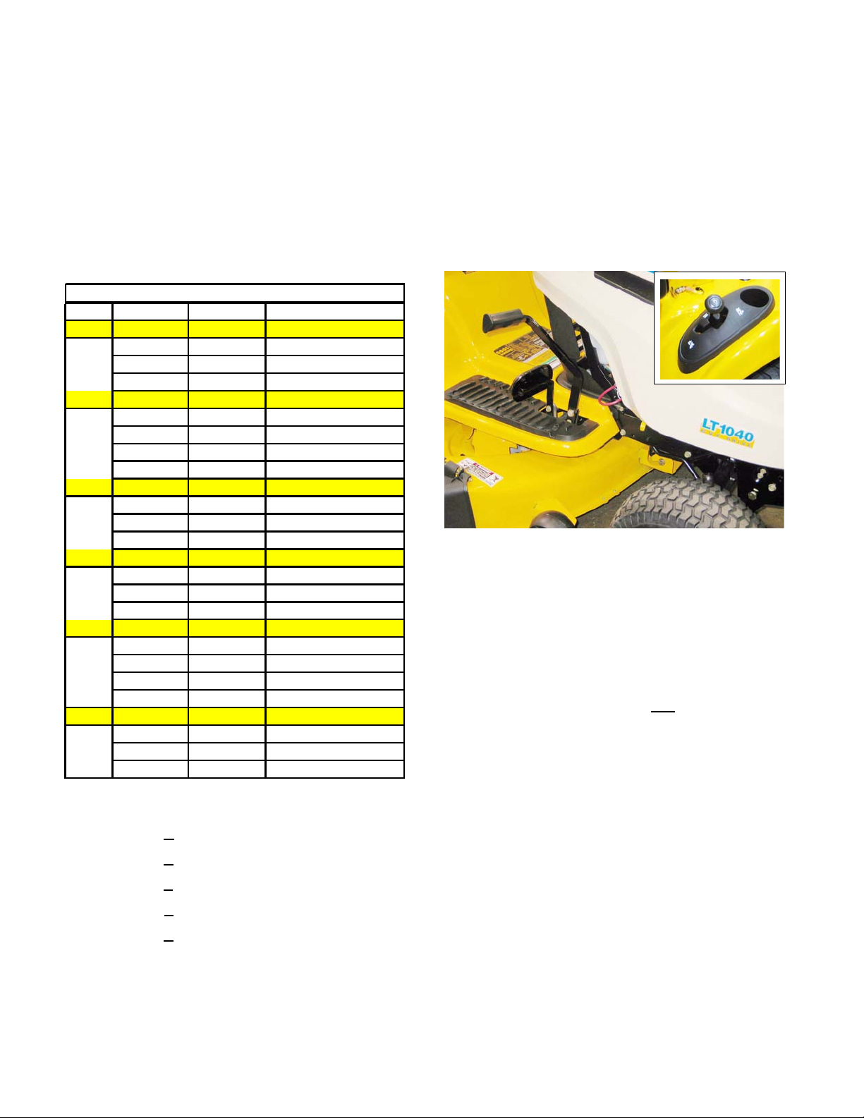
1.10. A Two-belt CVT system driving an MTD singlespeed transaxle is presently used only on the
LT1040 model. This system can be distin
guished by the gear selector (F-N-R) on the left
rear fender, and the simple drive pedal.
See Figure 1.10.
Figure 1.10
1.11. A similar two-belt CVT system was employed to
drive a heavy-duty transaxle in some 2002 and
2002 models having two forward speed ranges.
These are easy to identify by the presence o f the
gear selector lever between the operators knees
rather than on the fender.
1.12. All CVT driven 1000 and 1500 Series tractors
have a gear selector lever
the right side, near the brake pedal.
1.13. All Hydrostatic transaxles on the 1000 and 1500
Series are operated by a rocker pedal on the
right side, near the brake pedal.
1.14. A Hydro-Gear 310-0510 hydrostatic transaxle is
used on LT models having 20” rear tires. Hydro
static transaxles have a rocker pedal to control
forward and reverse direction and speed.
and a drive pedal on
-
-
• 13AP11CP
• 13AQ11BP
• 14AK13BK
756 - 50” 3-blade deck
756 - 50” 3-blade deck
756 - 54” 3-blade deck
2
Page 7
Series 1000 and 1500
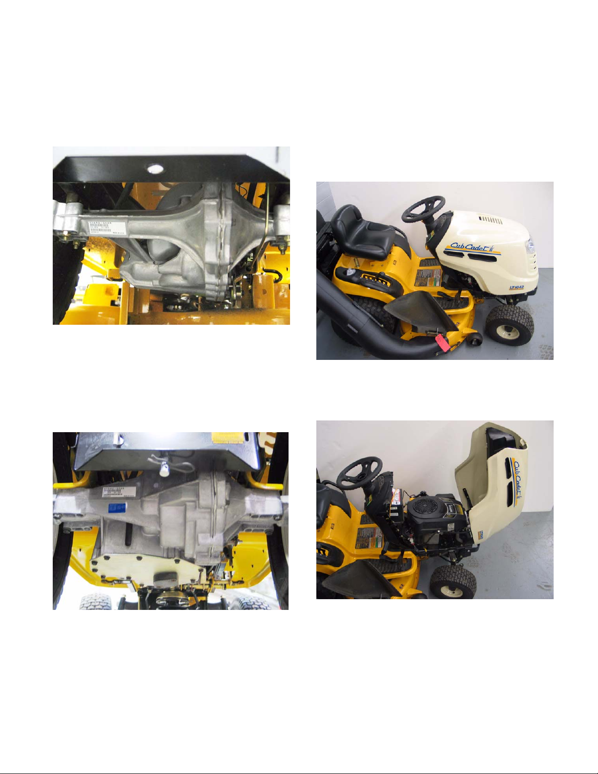
1.15. A Hydro-Gear 314-0610 hydrostatic transaxle
with a different final drive ratio is used on LT
models having 22” rear tires. Hydrostatic tran
saxles have a rocker pedal to control forward
and reverse direction and speed.
1.15.
Figure 1.15
See Figure
2. NEW HOOD DESIGN
-
2.1. Early 1000 and 1500 Series tractors used a variety of steel hoods and side panels. Later ones
resembled those used on the 2000 and 2500
Series tractors.
2.2. The hood presently used on the 1000 series
tractors is a molded 1-piece design.
2.2.
See Figure
1.16. A Hydro-Gear 320-3000 hydrostatic transaxle is
used on GT designated models. This is a sub
stantially heavier duty IHT than the one used in
the LT models. Hydrostatic transaxles have a
rocker pedal to control forward and reverse
direction and speed.
See Figure 1.16.
Figure 1.16
-
Figure 2.2
2.3. The 1000 Series hood opens from the back.
See Figure 2.3.
Figure 2.3
3
Page 8
Series 1000 and 1500
2.4. The 1000 Series hood can be easily removed:
See Figure 2.4.
Figure 2.4
• Disconnect the headlight wires
• Release the retaining springs
• Align the bolts in the hood with the slots in the
hinge.
• A pair of gas charged cylinders provide lift assist.
See Figure 2.5.
Gas lift Cylinders
Pivot Rod
Figure 2.5
2.6. A new spring-loaded latch was added to hold the
hood closed.
See Figure 2.6.
• Lifting the hood off of the tractor.
2.5. The hood used on the 1500 Series tractors for
2005 and 2006 is more substantial than that
used on the 1000 Series. It is a one-piece
molded design very similar to the one used on
the much larger 5000 and 6000 series tractors.
See Figure 2.5.
Figure 2.5
Figure 2.6
• It opens from the front.
4
Page 9
Series 1000 and 1500
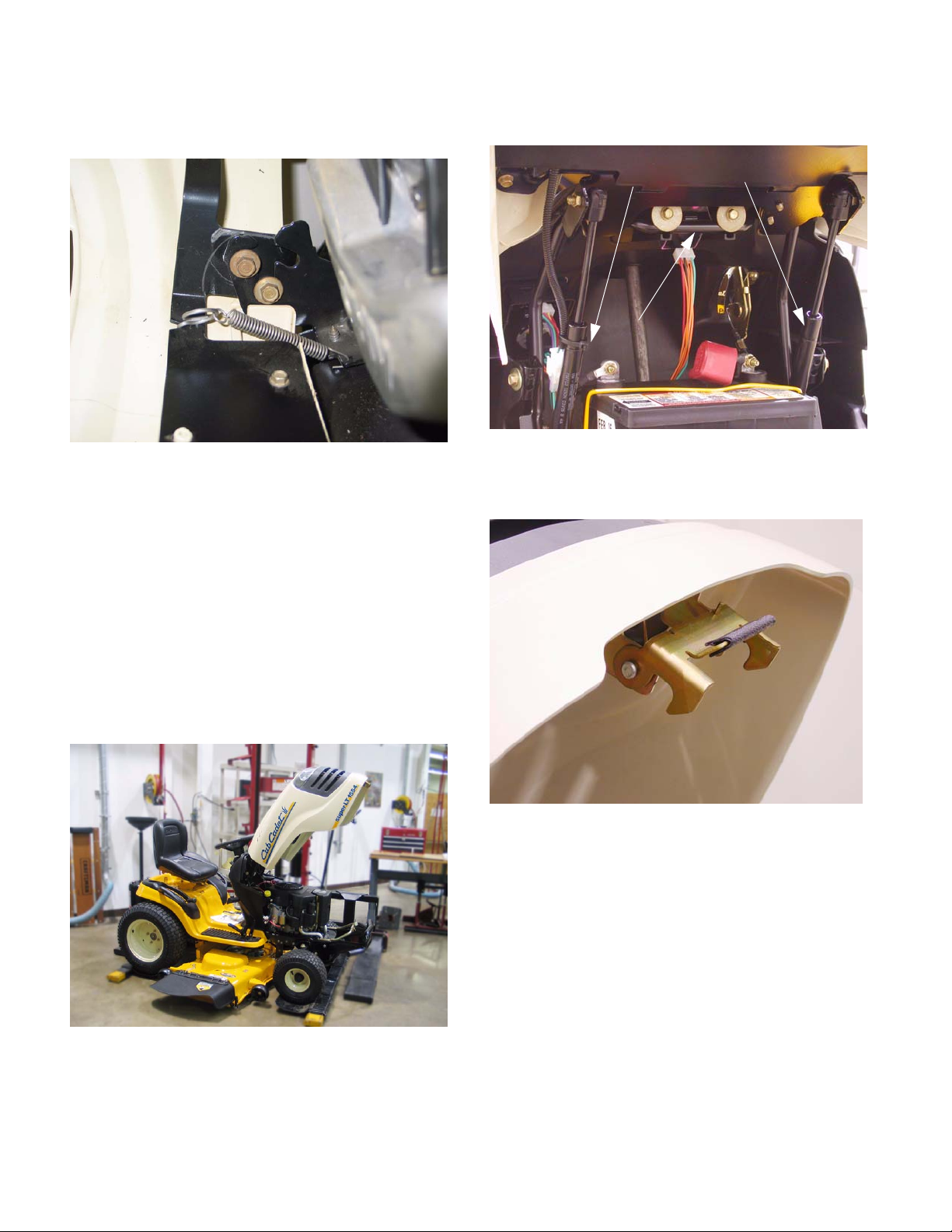
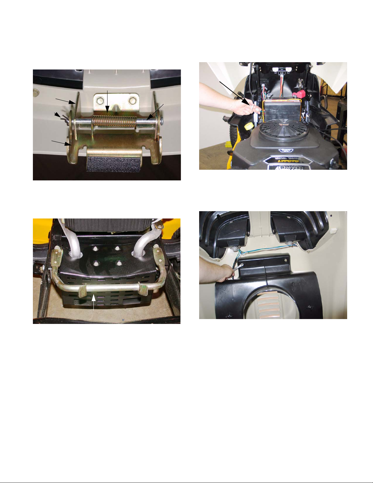
2.7. A torsion spring keeps the latch secure until the
lower pivot latch is intentionally pulled up, to
open the hood.
Upper
Pivot
Latch
Cotter
Pin
Lower
Pivot
Latch
2.8. The hood latches to a sturdy rod that is mounted
to the front of the frame.
See Figure 2.7.
Torsion Spring
Pivot
Rod
Figure 2.7
See Figure 2.8.
3.2. Disconnect headlight harness (plugged secured
to hood lift cylinder).
Headlight
Harness
3.3. Remove the air deflector baffle using a 3/8”
wrench.
See Figure 3.2.
Figure 3.2
See Figure 3.3.
Hood Latch Rod
Figure 2.8
3. HOOD PANEL REMOVAL: 1500 SERIES
NOTE: Use this procedure if the hood alone is to
be removed. Typical reasons might include
replacement because of damage to the hood, or
to ease access for other service.
3.1. Disconnect ground cable from battery using a
7/16” wrench.
Figure 3.3
3.4. Support the hood as it is being loosened.
3.5. Separate hood from hinge using a 3/8” wrench.
3.6. Lift hood off of tractor.
5
Page 10
Series 1000 and 1500
4. HOOD AND HINGE REMOVAL: 1500 SERIES NOTE: Use this procedure for more extensive
repairs. T ypical reasons may include dash p anel
removal, or the need for more working room
than simply removing the hood will provide.
4.1. Remove the battery: See Figure 4.1.
Figure 4.1
4.8. Hood installation notes: See Figure 4.8.
Figure 4.8
• Position the hinge support bar over the two
spacers that partially cover the threads of the
balls that the that hood support struts attach to.
The slots in the ends of the bar will fit over the
spacers.
• Disconnect the negative battery cable (black)
first, using a 7/16” wrench.
• Disconnect the positive battery cable (red) using
a 7/16” wrench.
• Remove the battery hold-down.
• Lift the battery from the tractor.
4.2. Disconnect the headlight harness. (Plug secured
to the hood lift cylinder).
4.3. Support the hood with an improvised prop-rod to
prevent damage.
4.4. Remove screws holding hinge support bar to
dash support using a 1/2” wrench.
4.5. Disconnect and remove the hood lift cylinders
using a small straight-blade screwdriver.
4.6. Remove screws & flat washers holding hinge
support bar to dash panel using a 3/8” wrench.
4.7. Lift hood and hinge assembly off of the tractor,
and remove it to a safe place.
• Support the hood with an improvised prop rod.
• Install the screws that hold the hinge support bar
to the dash support and instrument panel.
• Snap the hood support cylinder into place, and
remove the prop rod.
• The remainder of the installation process is simply the reversal of the removal steps.
6
Page 11
Series 1000 and 1500
5. REAR FENDER REMOVAL
5.1. It is necessary to remove the fender assembly
for access to the following service areas:
Figure 5.1.
Figure 5.1
• Fuel tank (hydrostatic drive riders)
• Lift-shaft assembly (except bushings)
See
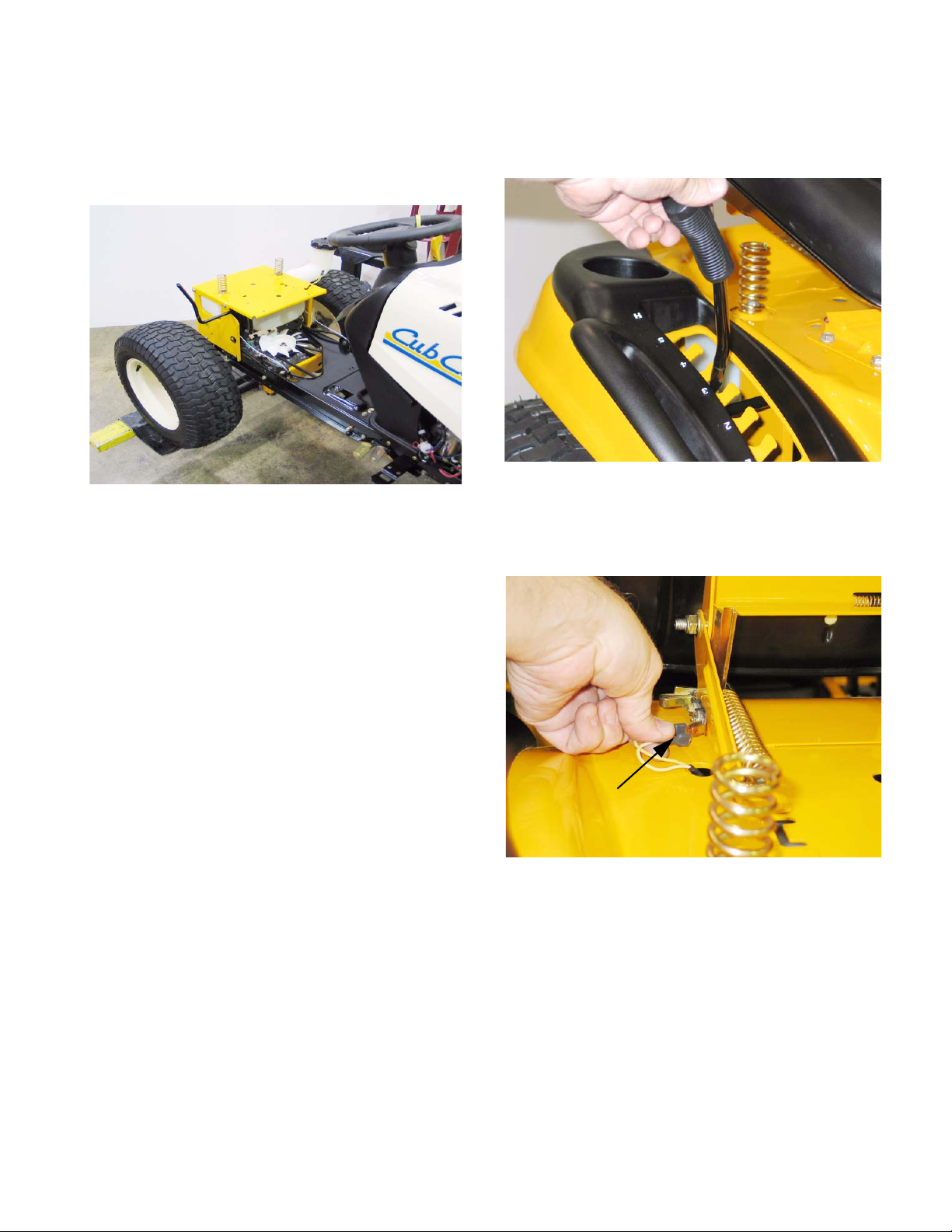
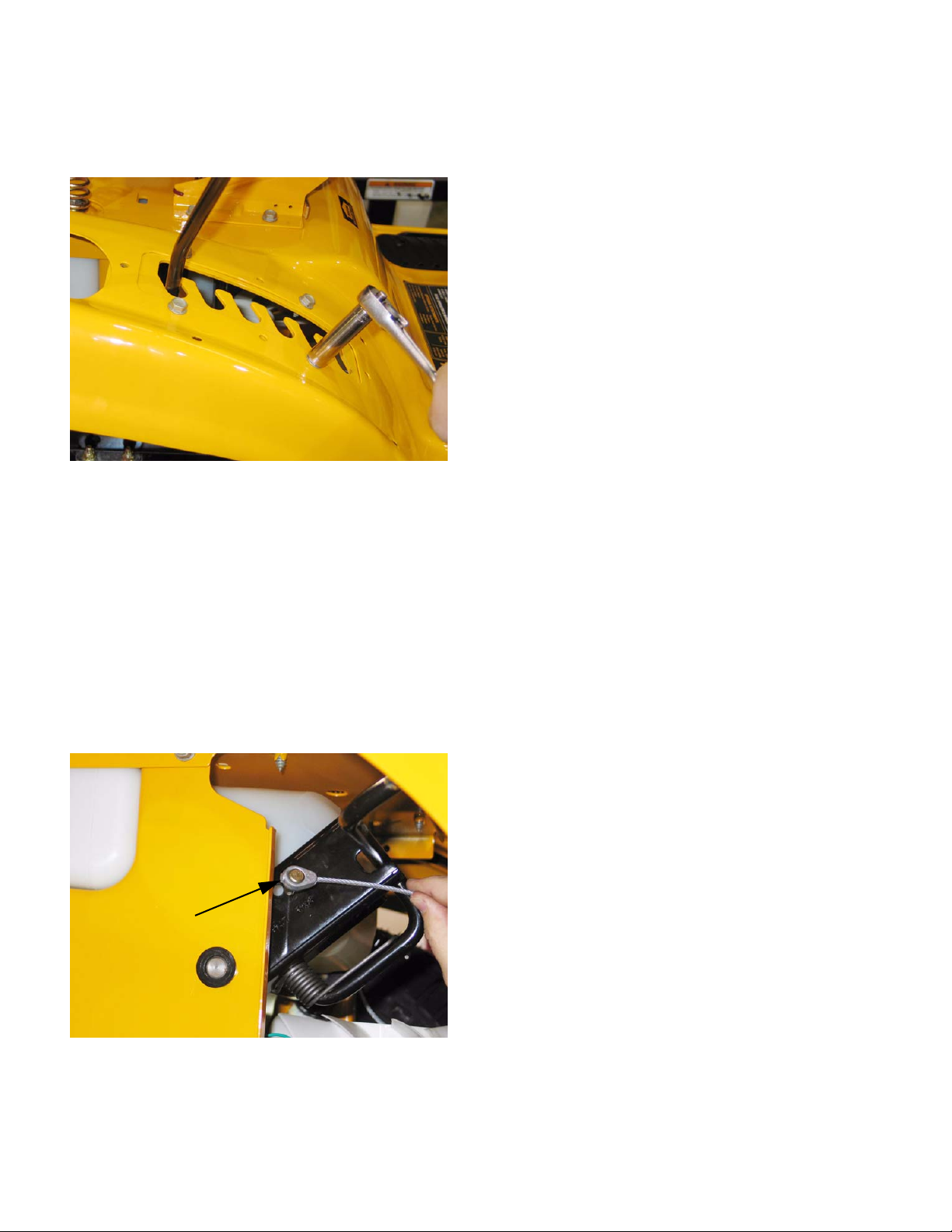
5.4. Remove the rubber grip from the cutting deck
height control handle atop the right rear fender.
See Figure 5.4.
Figure 5.4
5.5. Disconnect the two yellow wires from the seat
safety switch mounted to the left side seat
bracket.
See Figure 5.5.
• Deck lift cable removal
• Wiring harness inspection or removal
• Dash panel removal
• Traction drive belt idler pulley removal
• Traction drive belt tension arm removal
NOTE: At first-glance, fender removal appears
to be a substantial job. Skilled mechanics can
typically remove the fenders from a 1000 Series
Cub Cadet tractor in about 15 minutes, with an
equal amount of time required for installation.
5.2. Disconnect the ground cable from the negative
battery post using a 7/16” wrench.
5.3. Remove the cutting deck from the tractor.
Safety Switch Connectors
Figure 5.5
5.6. Release the gold colored extension spring from
the left side seat bracket using a length of starter
rope or a spring removal tool.
• gold colored spring: left seat bracket
• red spring: right seat bracket
• Only the gold colored spring must be removed
because it blocks access to the bolts that hold
the seat bracket to the frame.
7
Page 12
Series 1000 and 1500
5.7. Remove the four bolts that hold the seat brackets to the frame using a 1/2” wrench.
5.8. Remove the seat to a safe location.
5.9. Remove the hydro control pedal (or speed control pedal on CVT equipped models) using a T40 driver.
See Figure 5.9.
T-40 Screws
Figure 5.9
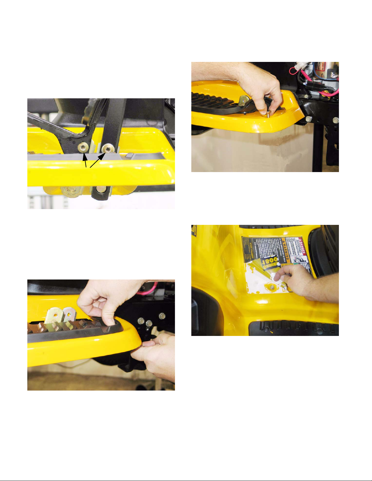
5.12. Peel-back the rubber foot pad to reach and
remove the carriage bolt.
Figure 5.12
5.13. Carefully peel-up each rear corner of the larger
instruction label located between the foot pads,
revealing two screws that hold the fender
assembly to the frame.
See Figure 5.12.
See Figure 5.13.
5.10. Remove the brake pedal using a T-40 driver
(upper screw) and a 9/16” wrench (lower screw).
5.11. Remove the nuts from the carriage bolts that
secure the front edge of each running board to
the frame bracket that supports it.
See Figure 5.11.
Figure 5.11
Figure 5.13
NOTE: If the previous steps are done with care,
the label can be reapplied, using some spray-on
contact adhesive if necessary.
• If the label shows signs of becoming damaged
by the peeling-back process, it should be
replaced during reassembly.
• Apply thumb pressure to the rubber foot pad,
directly above the nut / carriage bolt to hold the
square boss on the nut into the bracket, to prevent rotation.
• To identify and order a replacement label, note
the number printed on the lower right corner of
the label (“S32484 AC” typical). That number,
with a 777 prefix (777-S32484 AC) is usually the
part number of the label.
8
Page 13
Series 1000 and 1500
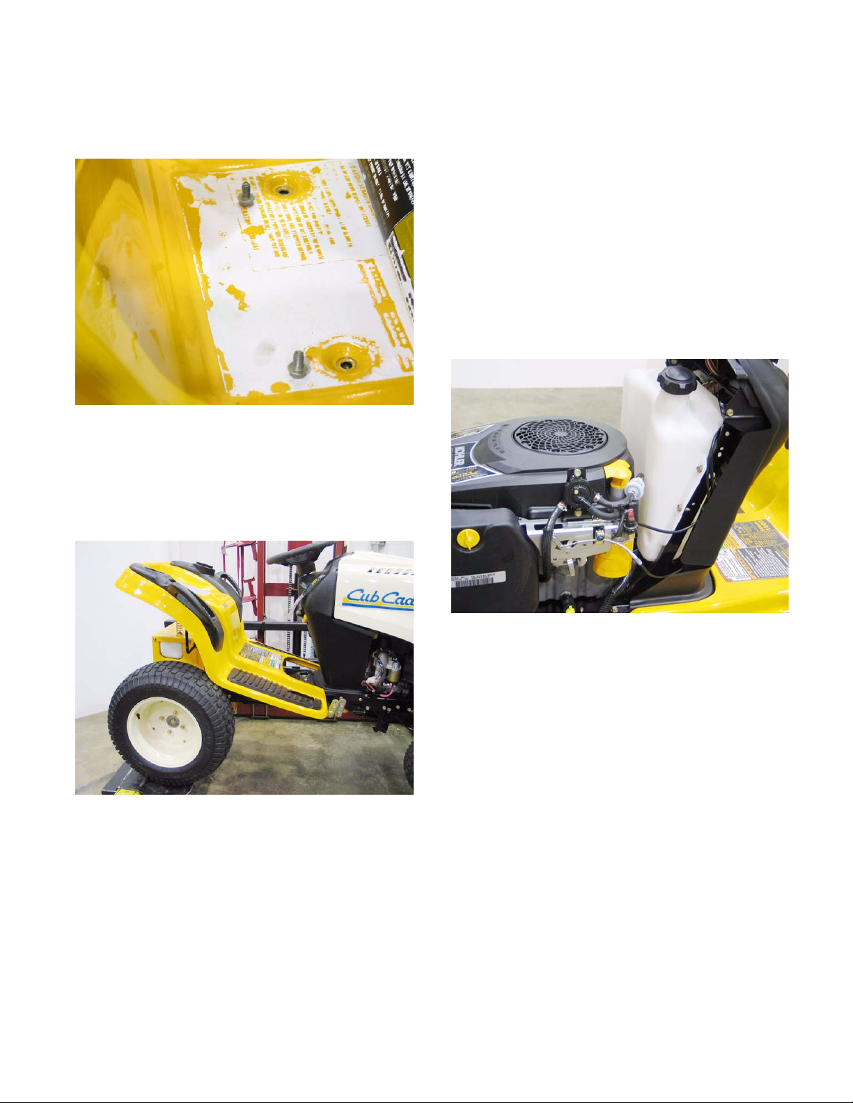
5.14. Remove the two screws that were revealed by
peeling-back the label. This can be done using a
3/8” wrench.
5.15. Remove the fuel filler cap.
5.16. Lift the fenders off of the tractor, maneuvering
them to clear the cutting deck height control
lever.
See Figure 5.16.
See Figure 5.14.
Figure 5.14
• When installing a large panel, start all of the
threaded fasteners, then go back and tighten
each after the panel is in position.
• Test the operation of all controls and safety features in a safe place, free of obstacles and bystanders before returning the tractor to service.
6. FUEL SYSTEM
6.1. While the 1000 and 1500 Series tractors are
built on the same frame, the fuel systems differ
substantially in layout.
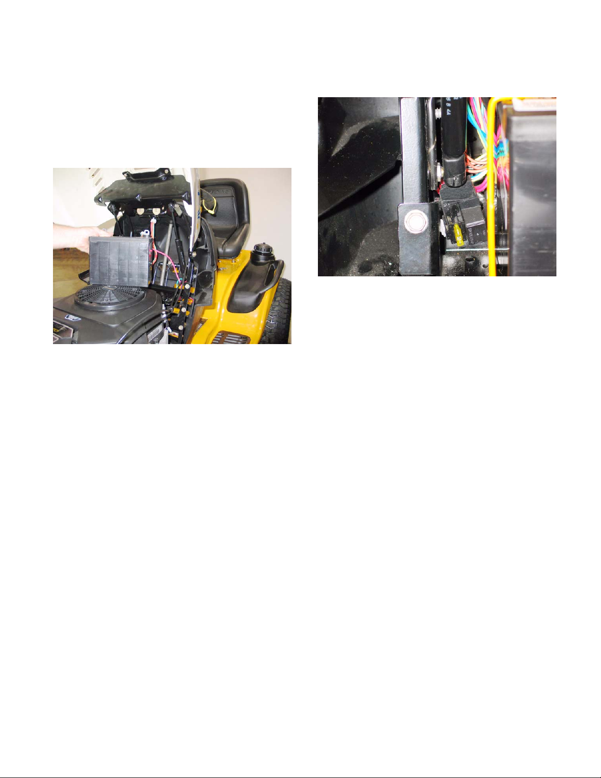
6.2. The 1000 Series tractors have the fuel tank
beneath the hood, with the battery located under
the seat.
See Figure 6.2.
Figure 5.16
5.17. Remove the fenders to a safe place.
5.18. Replace the fuel filler cap.
5.19. Installation notes:
• Confirm that the seat safety switch wires are
accessible before securing the fender.
• 144 in-lbs is adequate tightening torque for the
5/16”-18 screws and bolts removed in this procedure. (1/2” wrench or T-40 driver)
Figure 6.2
6.3. This positioning is necessary to provide easy
service access to the CVT drive system used on
the 1000 series tractors. The rear mounted bat
tery, and the tray that supports it are easily
removable.
6.4. The battery of the 1500 Series tractor is located
under the hood, with the fuel tank mounted
under the rear fenders.
-
9
Page 14
Series 1000 and 1500
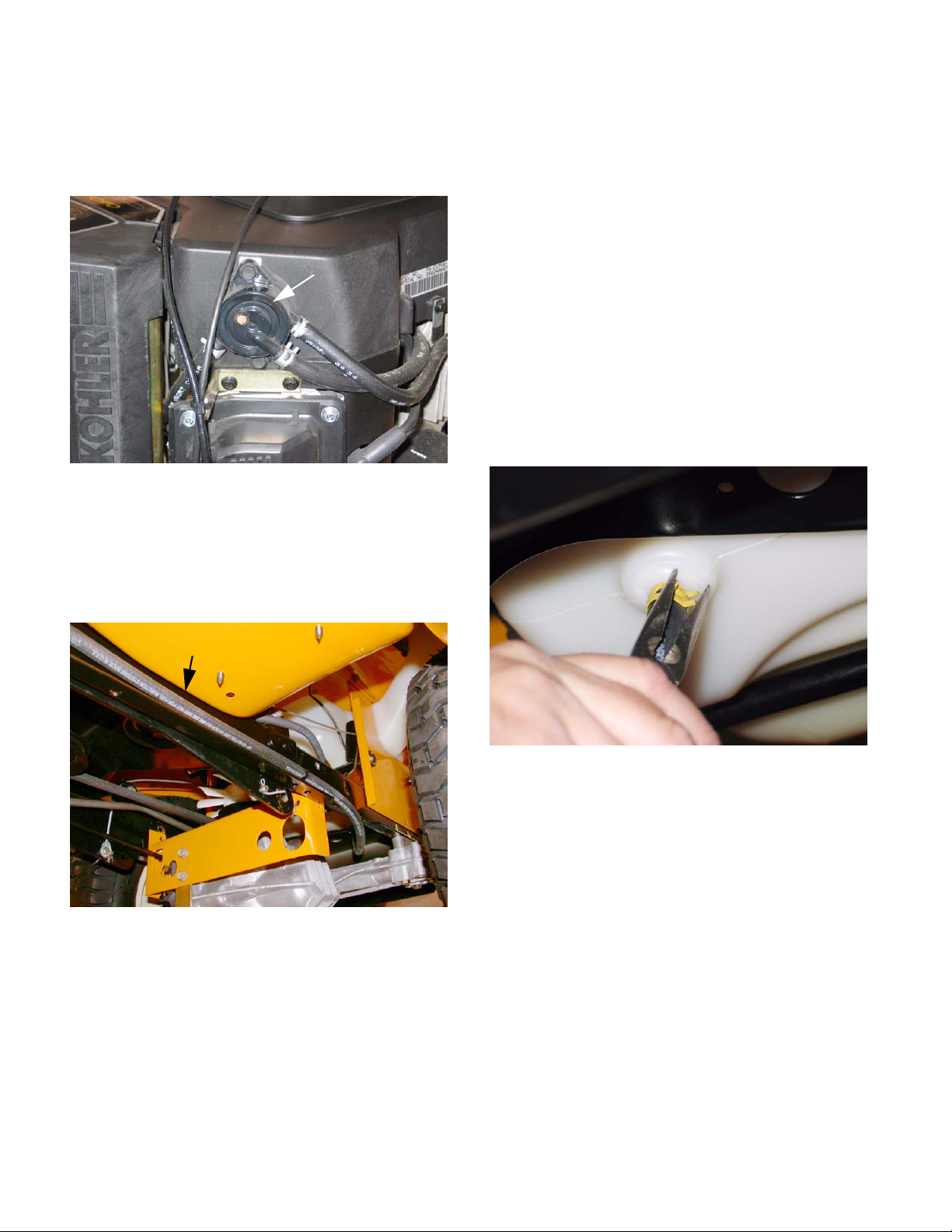
6.5. On current models of the 1000 and 1500 Cub
Cadet, the fuel is moved from the tank to the car
buretor by a vacuum-driven fuel pump that is
mounted to the engine.
Figure 6.5
6.6. The fuel line runs from a barbed fitting on the
bottom of the fuel tank to the fuel pump.
See Figure 6.5.
Fuel Pump
6.9. In the event that it is necessary to remove the
-
fuel tank, begin by removing the fenders as
described in the REAR FENDER REMOVAL
section of this manual.
6.10. Make provisions for draining any fuel that
remains in the gas tank: 24” of 1/4” fuel line, and
a suitable catch pan will be sufficient.
6.11. Pinch the fuel line about 6” from the fuel tank to
prevent the line from emptying (unless it needs
to be drained or replaced).
• Position the catch pan under the fitting on the
fuel tank.
• Have the extra length of fuel line handy.
6.12. Remove the hose clamp that secures the fuel
line to the fitting on the gas tank.
See Figure 6.12.
6.7. The 1500 series fuel line should be routed as
shown.
6.8. The fuel cap is vented.
• There are a few non-vented fuel caps that will fit
the filler neck of the 1000 and 1500 Series tractor.
See Figure 6.7.
Fuel Line
Figure 6.7
Figure 6.12
6.13. Quickly pull the fuel line off of the fitting, and
replace it with the extra hose. Direct the hose
into the catch pan.
6.14. When the tank is empty, dispose of any unusable fuel in a safe and responsible manner.
• Non-vented caps are used on the Cub Cadet Big
Country line of utility vehicles.
• Use of a non-vented cap on a 1000 or 1500
Series tractor will cause fuel supply issues.
10
Page 15
Series 1000 and 1500
6.15. Remove the plate that supp orts the seat brackets using a 1/2” wrench. See Figure 6.15.
Seat Bracket Plate
Figure 6.15
6.16. Lift the fuel tank out of the tractor.
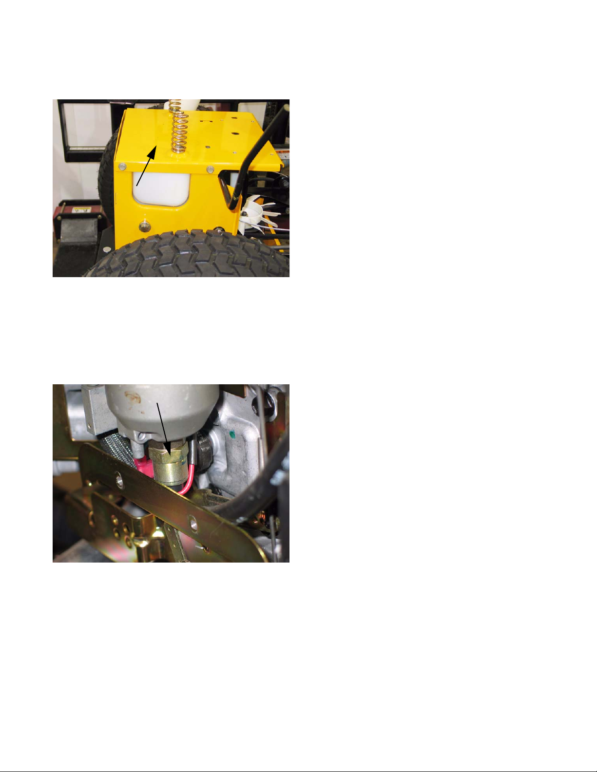
7. FUEL SHUT-OFF SOLENOID
7.1. In all models of the 1000 and 1500 Series Cub
Cadet riders, there is a fuel shut-off solenoid
mounted to the carburetor.
See Figure 7.1.
• When the solenoid does not have power, it
closes, stopping the flow of fuel.
• The solenoid usually emits an audible “click”
when power is applied or discontinued.
• If the solenoid does not click, it is not working. If
it does click, it cannot be assumed to be working
properly.
8. FUEL RELATED NO-START ISSUES
8.1. The leading industry cause of no-start and
engine performance problems is stale or out
dated fuel.
• In temperate regions of the country, fuel purchased during the summer may not be volatile
enough to ignite during the winter months.
• Similarly, “Winter” fuel may be cause performance issues if used into the summer months.
The gasoline companies taylor the contents of
their fuel blends to optimize performance, ta king
climate and geography into account.
• As fuel goes stale, the lighter end hydrocarbons
(more volatile elements) tend to evaporate, leaving the fuel less volatile.
-
Fuel Shutoff Solenoid
Figure 7.1
7.2. The fuel shut-off solenoid is a valve that is actuated by an electric coil.
• The fuel shut-off solenoid helps prevent “afterboom” when a hot engine is turned-off.
• The solenoid has power when the key is in the
run position and the safety switches on the tractor do not sense any unsafe conditions. When it
has power, the solenoid opens, allowing fuel to
reach the carburetor.
• In extreme cases, semi-solid residue will accumulate, damaging the fuel system.
• If a piece of equipment will sit unused during the
dormant season, the fuel system should be
drained completely, or preservative should be
added to the fuel according to the preservative
manufacturer’s instructions.
8.2. Alcohol content of the fuel should not exceed
10%.
• Small amounts of ethanol are fairly common in
fuel.
• Methanol is more destructive than ethanol, and
should be avoided.
• Alcohol absorbs water. Fuel that contains alcohol will also contain a certain amount of water.
The water will corrode any metallic parts of the
fuel system, and may cause freezing damage in
low temperatures.
• Products that purport to “dry” the fuel system are
generally isopropyl alcohol. The object is to resuspend the water that has settled out of the
alcohol the fuel already contains.
11
Page 16
Series 1000 and 1500
• Ether-based starting fluids should not be used,
and may void engine warranties if their use is
detected.
9. MUFFLER REMOVAL NOTE: There are a variety of mufflers on this
series of tractor depending on the year and
engine of the unit. this chapter will cover a few
different mufflers to give you the basics of muf
fler removal on this series.
NOTE: For all tractors, remove the bumper first.
• On units with side panels:
9.1. Remove the hood, side panels and grill.
NOTE: Make sure to disconnect the headlight
harness when you remove the grill and side pan
els.
9.2. Remove the self tapping hex cap screws securing the front frame assembly to the muffler shield
and muffler using a 1/2" socket.
See Figure 9.2.
9.7. Remove both hinge brackets. See Figure 9.7.
Hinge Bracket
-
-
9.8. Remove the four screws in the sides of the muf-
fler guard. Slide the muffler and muf fler guard of f
of the exhaust pipe(s).
Figure 9.7
See Figure 9.8.
Muffler Guard
Hex Cap Screws
Frame
Muffler Shield
Figure 9.2
9.3. Remove the muffler and guard.
NOTE: Muffler slides off of the ex haust pipe. It is
NOT fastened to the pipe.
9.4. Remove the four screws in the top of the muffler
guard. the muffler and muffler guard will now
separate.
9.5. Reassemble in reverse order.
• 1000 Series with one piece hood.
9.6. Remove hood as shown in section 2.
Figure 9.8
NOTE: You may have the tail pipe stickin g out of
the left side. If so slide the guard off of it first.
12
Page 17
Series 1000 and 1500
9.9. Remove the four screws going through the muffler support brackets into the muffler mounting
bracket.
9.10. The muffler will now slide off of the exhaust
pipe(s).
9.11. Remove the screws in the muffler mounting
brackets and lift the brackets off of the muffler.
9.12. Reassemble in reverse order.
• 1500 with one piece hood:
9.13. Open hood.
9.14. Remove bumper
See Figure 9.9.
Muffler Support Bracket
Figure 9.9
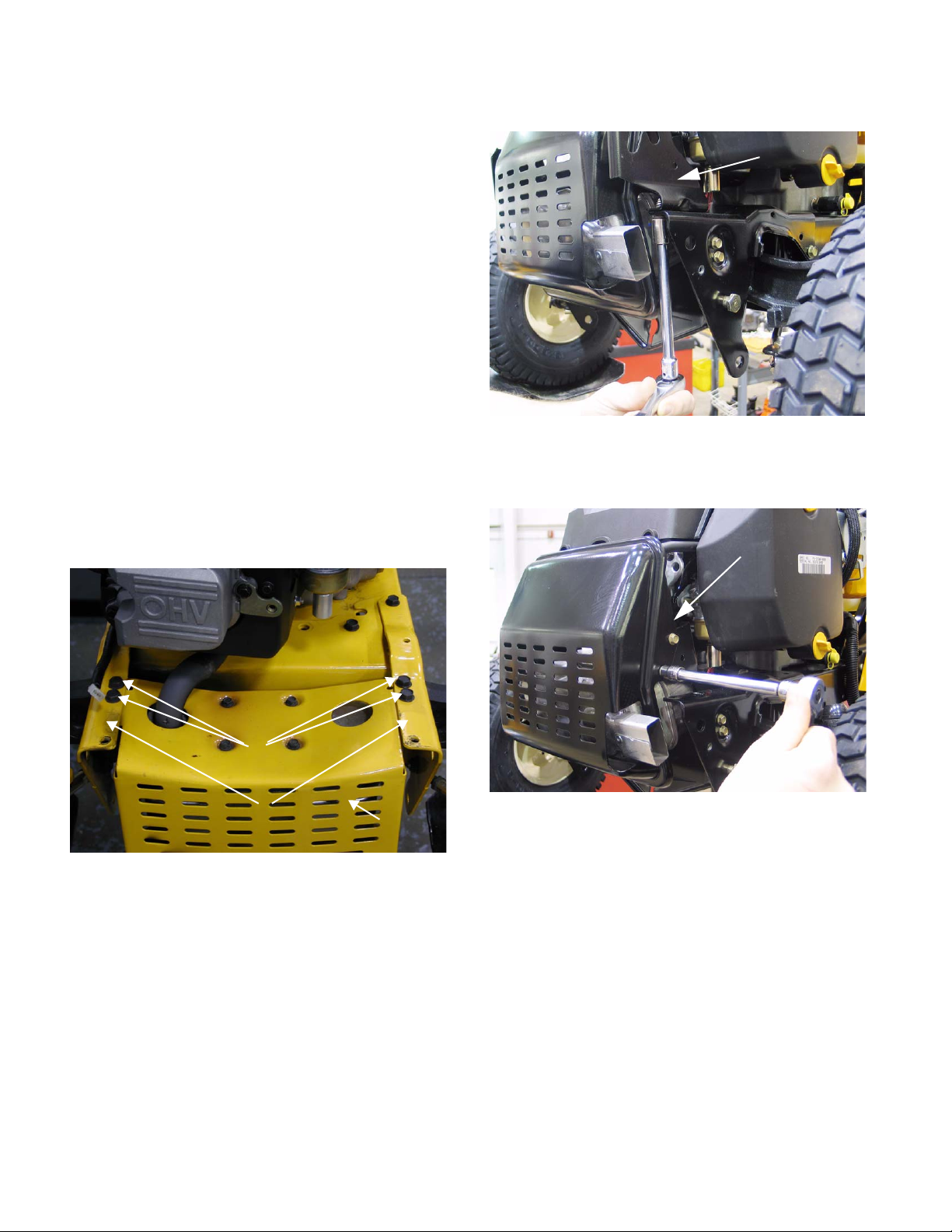
9.16. Remove the four screws holding the muffler
guard to the front muffler support brackets.
Figure 9.16.
Remove these hex screws. (two on each side)
Figure 9.16
NOTE: The rear two screws will be accessible
from the top. the front two screws will be acces
sible from the bottom.
9.17. Slide the muffler and muffler guard off of the
exhaust pipe(s).
9.18. Remove the four screws in the top of the muf fler
guard. Lift the muffler guard off of the muffler.
9.19. Reassemble in reverse order.
See
-
9.15. Remove the two clevis pins in the deck front stabilizer bracket.
10. CUTTING DECK REMOVAL
10.1. Place the PTO switch in the off position.
10.2. Lower the lift lever to the lowest setting.
13
Page 18
Series 1000 and 1500
10.3. Remove the PTO belt from electric P TO clutch.
See Figure 10.3.
Idler
Electric PTO
clutch
(earlier production)
Figure 10.3
NOTE: On some models you will need to
remove the belt guide first.
NOTE: On earlier production models you need
to slip the belt off of the idler pulley before you
remove the belt from the PT O clutch.
10.7. Slide the deck forward and release the front stabilizer rod. DO NOT DROP the deck to the
ground.
See Figure 10.7.
Front
stabilizer
rod
Figure 10.7
10.8. Slide the deck toward the right side of he tractor
and remove it from under the tractor.
CAUTION: Remove the deck stabilizer assembly from the tractor prior to moving the unit.
10.4. Pull the rear deck support pins outward from the
deck lift arms.
See Figure 10.4.
Lift arm
Deck support
pin
Figure 10.4
10.5. Pivot the deck support pins to the rear.
10.6. Raise the lift lever to the highest setting. This will
raise the lift arms up and out of the way of the
deck assembly.
NOTE: Depending on the model and deck, some
units have a J-bolt for the front stabilizer bar
instead of the U-bolt. On those units you can line
up the coined spot stamped in the middle of the
bolt with the slot in the bracket and slide it off.
See Figure 10.8.
U-Bolt Stabilizer
J-Bolt Stabilizer
Figure 10.8
14
Page 19
Series 1000 and 1500
11. DECK LIFT SHAFT ASSEMBLY
11.1. If the deck lift shaft itself requires removal, first
remove the cutting deck.
11.2. Remove the fenders as described in the
FENDER REMOVAL section of this manual.
11.3. Disconnect the deck lift assist spring that
extends from the deck lift shaft to the transaxle
torque bracket using a length of starter rope or a
spring tool.
Deck Lift Assist Spring
See Figure 11.3.
1 1.6. With the deck height control lever all the way for-
ward, remove the hairpin clips that secure the
deck lift cables to the arms on the deck lift shaft.
See Figure 11.6.
Deck Lift Cable
Figure 11.6
1 1.7. Remove the E-clip from each end of the lift-shaft.
See Figure 11.7.
Figure 11.3
11.4. On models built in 2004 and prior, the lift assist
springs extend rearward to a pair of openings
with mounting tabs in the back surface of the
upper frame.
See Figure 11.4.
Mounting Tabs
Figure 11.4
E-clip
Figure 11.7
11.8. Pry the bushings that support the lift shaft out of
the frame.
11.5. Unbolt the seat bracket mounting plate from the
frame (4 screws) using a 1/2” wrench. This will
allow the fuel tank to be lifted slightly for clear
ance, but the tank need not be removed.
-
15
Page 20
Series 1000 and 1500
11.9. Slide the lift shaft assembly to the right, providing clearance to remove the left end of the shaft
from the frame.
11.10.Slide the lift shaft back to the left to remove it
from the tractor.
11.11.On the bench, relieve torsion spring pressure
between the lift shaft and the lever that controls
it using a length of starter rope.
11.11.
See Figure 11.9.
Lift Shaft
Figure 11.9
See Figure
bushing, it should be a dry graphite or PTFE
based lube.
• Replace the bushings an E-clips if they show
signs of wear.
• Reverse the removal process to install the lift
shaft.
• Connect the cables and install the bushings prior
to connecting the tension spring between the lift
shaft arm and the transaxle torque bracket.
12. LIFT SHAFT BUSHINGS
12.1. The most common item on the lift shaft assembly to require service is likely to be the bushings
that support the shaft. These bushings are visi
ble beneath the fender. See Figure 12.1.
Bushing
-
Start er Rope
Torsion Spring
Figure 11.11
11.12.Rotate the lever to align the coined “ears” with
the slots in the lift shaft arm, allowing separation
of the lever from the arm.
11.13.Assembly notes:
• Because of the dusty environment that many
mowers operate in, grease applied to this bushing may accelerate wear rather than prevent it. If
any lubricant is used between the shaft and the
Figure 12.1
12.2. When performing normal maintenance that
requires deck removal, inspect the lift shaft
bushings while the weight of the deck is
removed from them.
• These bushings are normal wear items.
• Grasp the lift shaft and apply up and down force.
• Watch for shaft motion within the bushings.
• Larger decks, such as the 50” and 54” ( P and K)
decks will place a greater load on the bushings.
• Worn bushings may cause deck leveling issues.
12.3. To replace the bushings, the weight of the deck
should be removed from the deck lift cable.
Remove the cutting deck before attempting to
remove the bushings.
16
Page 21
Series 1000 and 1500
12.4. Disconnect the deck lift assist spring that
extends from the deck lift shaft to the transaxle
torque bracket using a length of starter rope or a
spring tool.
Deck Lift Assist Spring
12.5. Remove the E-clip that holds each shouldered
hex bushing into the tractor frame. Replace one
bushing at a time.
12.6. Pry the worn bushing out of the hole.
See Figure 12.4.
Figure 12.4
13.3. Remove the rear tires using a 3/4” wrench.
See Figure 13.3.
Figure 13.3
13.4. Remove the handle from the rear fenders using
a 3/8” wrench. The screws are accessible from
inside the rear fender.
See Figure 13.4.
Handle Screws
12.7. Clean any dirt or corrosion from the surface of
the lift shaft that contacts the bushing.
NOTE: Because of the dusty environment that
many mowers operate in, grease applied to this
bushing may accelerate wear rather than pre
vent it. If any lubricant is used between the shaft
and the bushing, it should be a dry graphite or
PTFE based lube.
12.8. Insert the new bushings, and secure them with
the E-clips.
12.9. Check deck levelness, and make any necessary
adjustments before returning the tractor to ser
vice.
13. DECK LIFT CABLES AND PULLEYS NOTE: The deck lift cables and pulleys can be
replaced without removing the rear fenders.
13.1. To remove the deck lift cables, remove the cutting deck.
13.2. Lift and safely support the rear of the tractor.
-
-
Figure 13.4
17
Page 22
Series 1000 and 1500
13.5. Remove the notched plate that the deck height
control lever seats against in the fender, using a
1/2” socket.
13.6. Push the deck height control lever as far forward
as it will go, and secure the lever in that position.
13.7. Remove the pulley that carries the deck lift cable
using a 1/2” wrench and a 5/8” wrench.
13.8. Remove the E-clip from the same end of the lift
shaft that the cable is being removed from. This
will allow the lift shaft to be pushed-in slightly,
providing clearance for the pin.
13.9. Remove the hairpin clip that secures the pin on
the top end of the cable to the arm on the deck
lift shaft.
See Figure 13.5.
Figure 13.5
See Figure 13.9.
13.10.Remove the hairpin clip that secures the pin to
the lift arm, and remove the cable.
13.11.Installation notes:
• Reverse the removal process to install the
cables and pulleys.
• Because of the dusty environment that many
mowers operate in, grease applied to the ca ble
or pulley may accelerate wear rather than prevent it. If any lubricant is used on the pulley, it
should be a dry graphite or PTFE based lube.
• Replace the pulleys and cables if they show
signs of wear.
• Check deck level before returning the tractor to
service.
• Tighten fasteners to the following torques:
Lug nuts 75ft-lbs (Nm)
Screws, handle to fender 60 in-lbs (Nm)
Screws, plate to fender 144in-lbs (Nm)
Shoulder bolts, pulley 144 in-lbs (Nm)
14. LEVELING THE CUTTING DECK NOTE: Prior to leveling the mowing deck, per-
form the following steps:
• Check the tire pressure. The front tires will be
approximately 14 PSI, and the rear tires will be
approximately 10 PSI.
• Place the tractor on a level surface.
• Depress and lock the parking brake.
Deck Lift Cable
Figure 13.9
NOTE: Early models used a removable clevis
pin. Current production cables have captive
pins.
• Place the cutting deck in cutting position 3 or 4.
SIDE TO SIDE ADJUSTMENT
IMPORTANT: The cutting deck must be even
side to side.
18
Page 23
Series 1000 and 1500
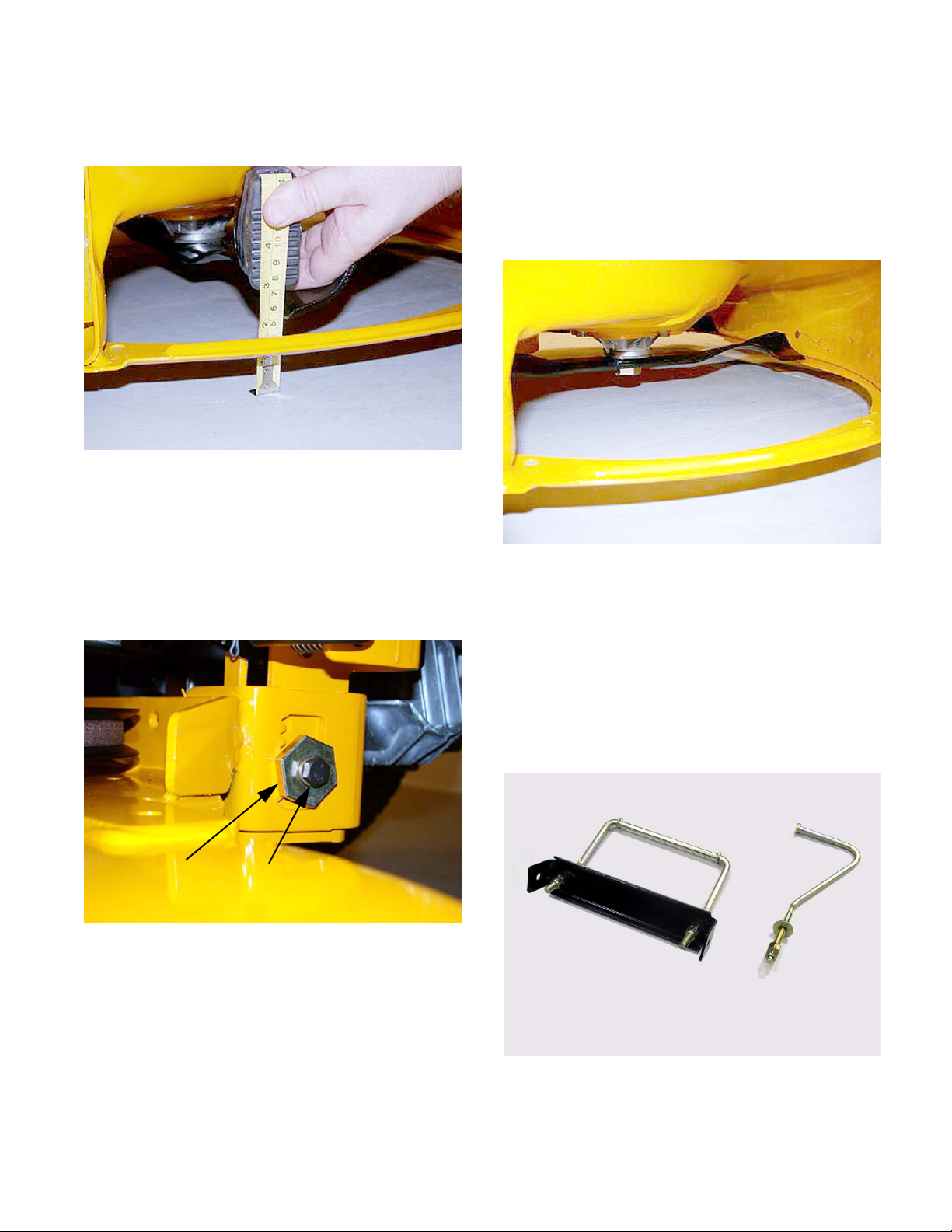
14.1. Using a work glove or rag, rotate the blades until
they are cutting edge tip to cutting edge tip (per
pendicular) to the tractor. See Figure 14.1.
Figure 14.1
14.2. Measure the outer blade tips to ground. Both
measurements taken should be equal.
NOTE: If an adjustment is needed, perform the
following steps:
FRONT TO REAR ADJUSTMENT
-
IMPORTANT: The front of the deck will be
between 1/4” and 3/8” lower in the front than the
rear of the deck.
14.6. Using a work glove or a rag, rotate the blades
until they are parallel with the tractor frame.
Figure 14.6.
Blades parallel with frame
Figure 14.6
See
14.3. Loosen (DO NOT REMOVE) the hex cap screw
on the left deck hanger bracket using a 1/2” an d
a 3/4” wrench.
Adjustment Gear Hex Cap Screw
14.4. Rotate the 3/4” deck adjustment gear right or left
until the deck is level side to side and both blade
tips to ground are equal in measurement.
14.5. Retighten the hex cap screw on the left deck
hanger using a 1/2” and a 3/4” wrench wh en th e
proper adjustment has been achieved.
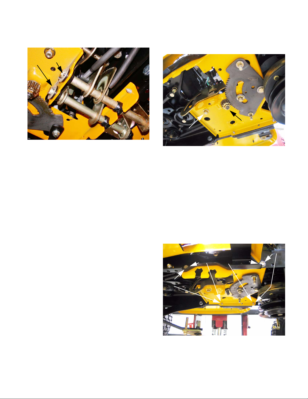
See Figure 14.3.
Figure 14.3
14.7. Measure the front blade tips to the ground.
14.8. Measure the rear blade tips to the ground.
14.9. Make certain the front blade tips are 1/4” to 3/8”
lower than the rear blade tips.
NOTE: If an adjustment is needed, perform the
following steps:
14.10.There two types of stabilizer rods. A U-bolt type
and a J-bolt type.
U-Bolt Stabilizer
See Figure 14.10.
J-Bolt Stabilizer
Figure 14.10
19
Page 24
Series 1000 and 1500
• For the U-bolt style:
14.11.Loosen both lock nuts securing the adjustment
nuts on the front of the deck stabilizer bracket
using a two 3/4” wrenches.
Lock Nuts
Adjustment Nuts
Figure 14.11
14.12.Locate both adjustment nuts on the front side of
the deck stabilizer bracket.
14.13.Tighten both nuts to r aise the front of the deck or
loosen both nuts to lower the front of the deck
using a 3/4” wrench.
NOTE: Make sure you count the numbe r of turns
you put on the first nut and put the same number
on the second nut. both nuts must be moved
equally.
14.14.Retighten both lock nuts to jam the adjustment
nuts into position when the proper adjustment
has been achieved.
See Figure 14.11.
• For the J-bolt Style:
14.15.The J-bolt style stabilizer is adjusted in a similar
fashion. Loosen the single lock nut away from
the adjustment nut using two 3/4” wrenches.
Lock Nut Adjustment Nut
Figure 14.15
14.16.To lower the front of the deck loosen the adjustment nut on the J-bolt. To raise the front of the
deck tighten the lock nut. Tighten the lock nut
against the adjustment nut when finished.
15. DASH PANEL REMOVAL
15.1. Remove fender, as described in the FENDER
REMOVAL section of this manual.
15.2. For the 1500 remove the hood and battery, as
described in the HOOD REMOVAL section of
this manual.
• For the 1000 remove the fuel tank by first removing the fuel cap. place a piece of plastic over fuel
tank opening and put fuel cap back on.
• Remove the four 1/2” screws holding the fuel
tank in place.
• Lift the fuel tank and place on top of engine or
clamp the fuel line and remove it from the fuel
pump and remove fuel tank from unit.
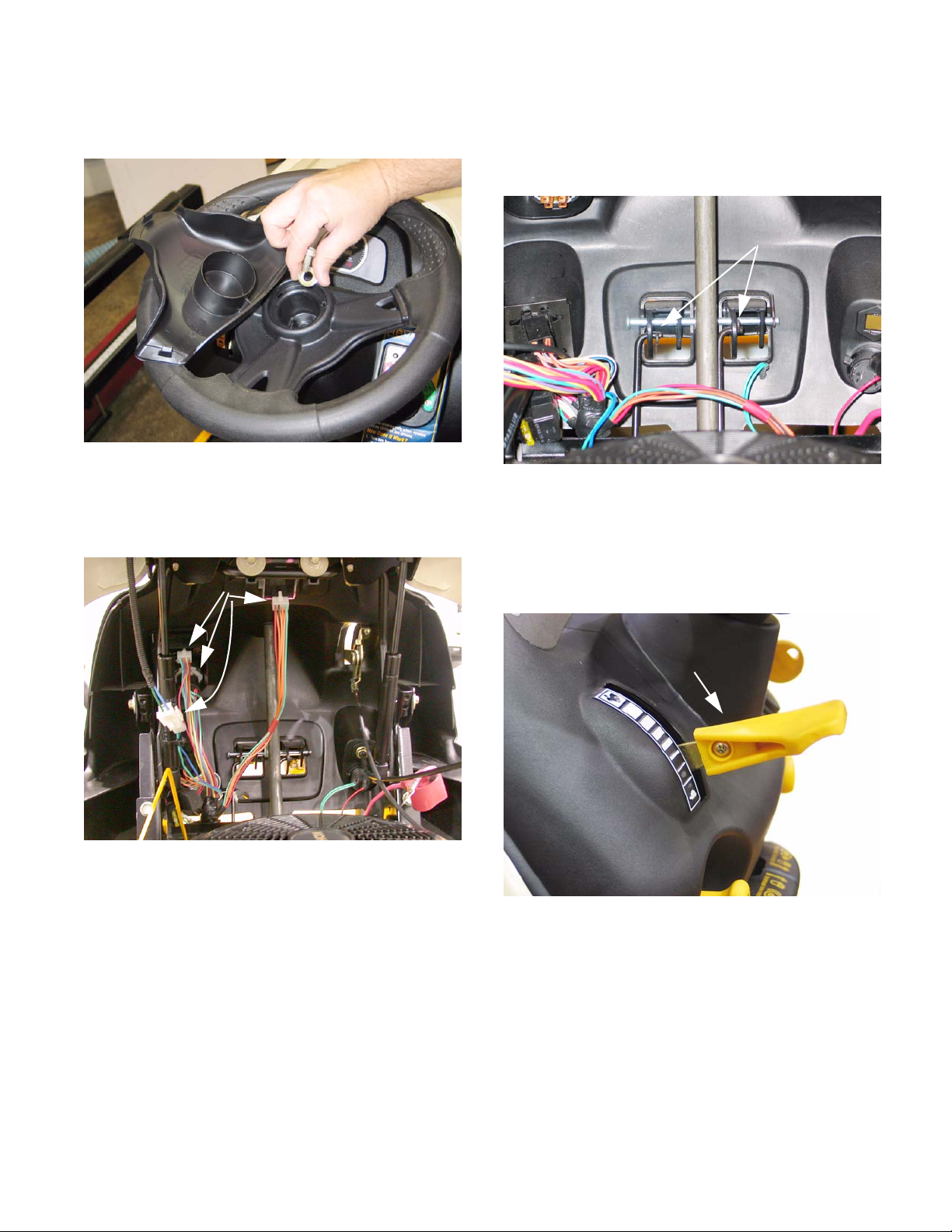
15.3. Pry the cap off the center of the steering wheel.
20
Page 25
Series 1000 and 1500
15.4. Remove the steering wheel from the steering
shaft using a 1/2” wrench.
Figure 15.4
15.5. Disconnect the following dash-mounted electrical devices by unplugging the molded connectors: See Figure 15.5.
Molded connectors
See Figure 15.4.
15.6. Disconnect the rods that connect the Park Brake
and Cruise Control mechanisms to the levers on
the dash that control those features by removing
the hairpin clips.
15.7. Remove the knob from the throttle lever using a
phillips head screwdriver, then remove the
screws that hold the throttle assembly to the
dash panel.
See Figure 15.6.
Hairpin clips
Figure 15.6
See Figure 15.7.
Figure 15.5
NOTE: Image shows 1500 dash. 1000 ser ies
dash components are in a similar location.
• Key switch and OCR module
• PTO Switch
• Hour meter / Monitor
• Accessory power port - if present.
Throttle
Lever
Figure 15.7
15.8. On models with a separate choke cable, disconnect the choke cable at the engine end. If the
technician prefers, they may also choose to dis
connect the throttle cable at the engine end.
15.9. Remove the remaining screws that hold the
dash panel to the tractor, and remove the dash.
• Two socket-head cap scre ws (T -40) at each side
of the base of the dash panel (four total).
-
21
Page 26
Series 1000 and 1500
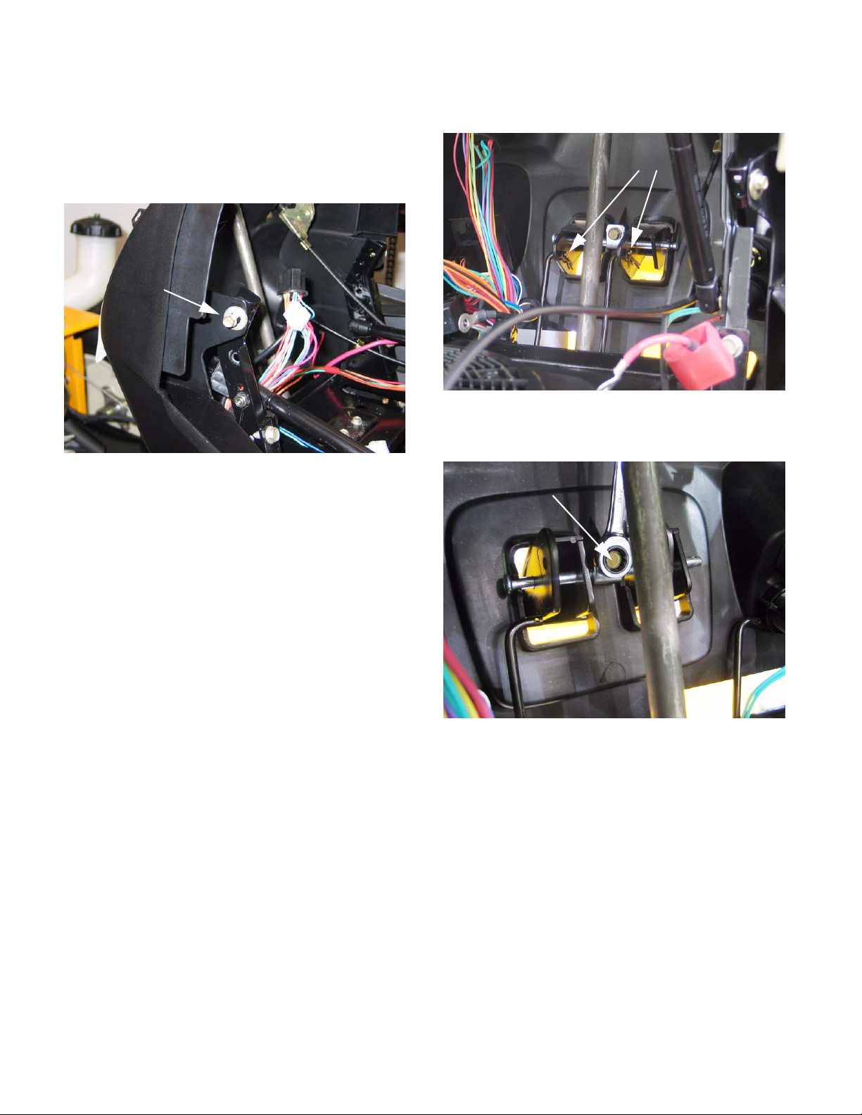
• Two hex-head cap screws holding the rear
flange of the dash to the frame (1/2” wrench)
• Two hex-head cap screws holding the top of the
dash to the dash support (3/8” wrench).
See Figure 15.9.
Hex-head cap screw
Figure 15.9
15.10.Reverse the removal process to install the dash
panel.
16.4. Remove the hair pin clips holding the linkages to
the levers in the dash.
Figure 16.4
16.5. Remove the screw holding the pivot rod in place.
See Figure 16.5.
Pivot Rod Hex Screw
See Figure 16.4.
Hairpin Clips
• Test the operation of all safety features in a safe
area that is clear of obstacles and bystanders
before returning the tractor to service.
• Test the operation of all controls in a safe area
that is clear of obstacles and bystanders before
returning the tractor to service.
16. CRUISE CONTROL AND PARK BRAKE LINKAGES
16.1. Open the hood.
16.2. On the 1000 series you need to remove the fuel
tank. on the 1500 series you need to remove the
battery.
16.3. The procedure for removing the park brake linkage and the cruise control linkage is the same.
you can remove both at the same time.
Figure 16.5
16.6. Remove the hair pin clip in the pivot rod.
16.7. Work the pivot rod out. sliding it out to the right.
the levers will fall out as the rod clears them.
16.8. Raise the unit off of the ground.
16.9. Remove the brake and drive pedals.
22
Page 27
Series 1000 and 1500
16.10.Remove the cotter pins in the brake pedal shaft
and the drive pedal shafts.
Cotter Pins
Figure 16.10
16.11.Slide the drive pedal to the right. The inboard
bushing and washer can now be removed. Con
tinue working the drive pedal shaft to the right
and slip it out of the unit.
16.12. Remove the hair pin clip in the brake rod and
disconnect it from the brake pedal shaft.
16.13.Remove the return spring from the brake pedal
shaft.
16.14.Slide the brake pedal shaft to the right and
remove the inboard bushing and washer. Con
tinue sliding the brake pedal shaft to the right
and work it off of the unit.
16.15.Remove both drag links from the tractor.
See Figure 16.10..
-
16.16.Remove the lock nut from the bottom of the
steering shaft. Then slide off the steering shaft
gear.
See Figure 16.16.
Lock Nut
Hex Nut
Figure 16.16
-
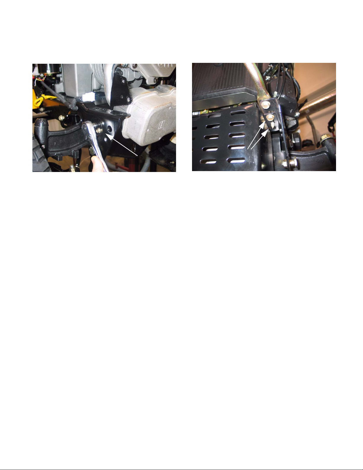
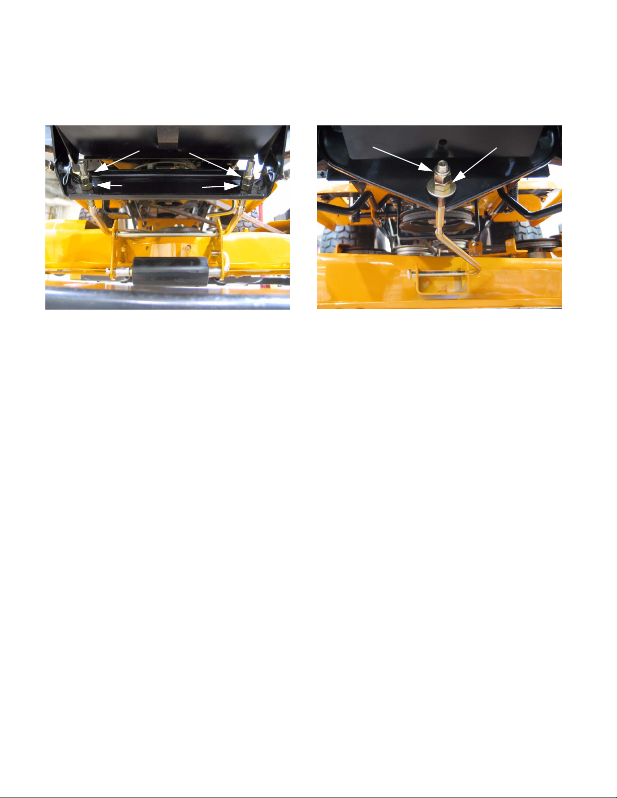
16.17.Reaching up through the open in g whe r e the
pedal shafts were, place a 9/16” wrench on the
head of the bolt located in the center rear of the
subframe. Using a 9/16” socket, remove the nut.
See Figure 16.16.
NOTE: There is a sleeve on this bolt that acts as
a spacer between the sub-frame and frame. Be
aware of this sleeve when you lower the sub
frame in a later step.
16.18.There are four screws holding the subframe to
the tractor.Two on each side. Loosen the two
front screws and remove the two rear screws.
See Figure 16.18.
-
NOTE: Make sure to keep the drag links separate so the you know which one is for the left and
which one is for the right. they are not marked
and they are not interchangeable.
Loosen these two.
Sub Frame Hex Screws
Remove these two.
Figure 16.18
23
Page 28
Series 1000 and 1500
16.19.Pivot the subframe down. Be careful of the
spacer on the bolt and the hex flange bushing for
the steering shaft, they will fall out.
16.20.You now have access to the cruise linkage and
cam lock. You also have access the park brake
linkage and locking plate.
Cruise Control Rod.
Parking Brake Rod
Figure 16.20
16.21.Remove the hair pin clips on the linkages.
Remove the linkages.
See Figure 16.20.
Cam Lock
17.3. Remove the battery hold-down, remove the battery and the battery tray. See Figure 17.3.
Battery Hold Down
Figure 17.3
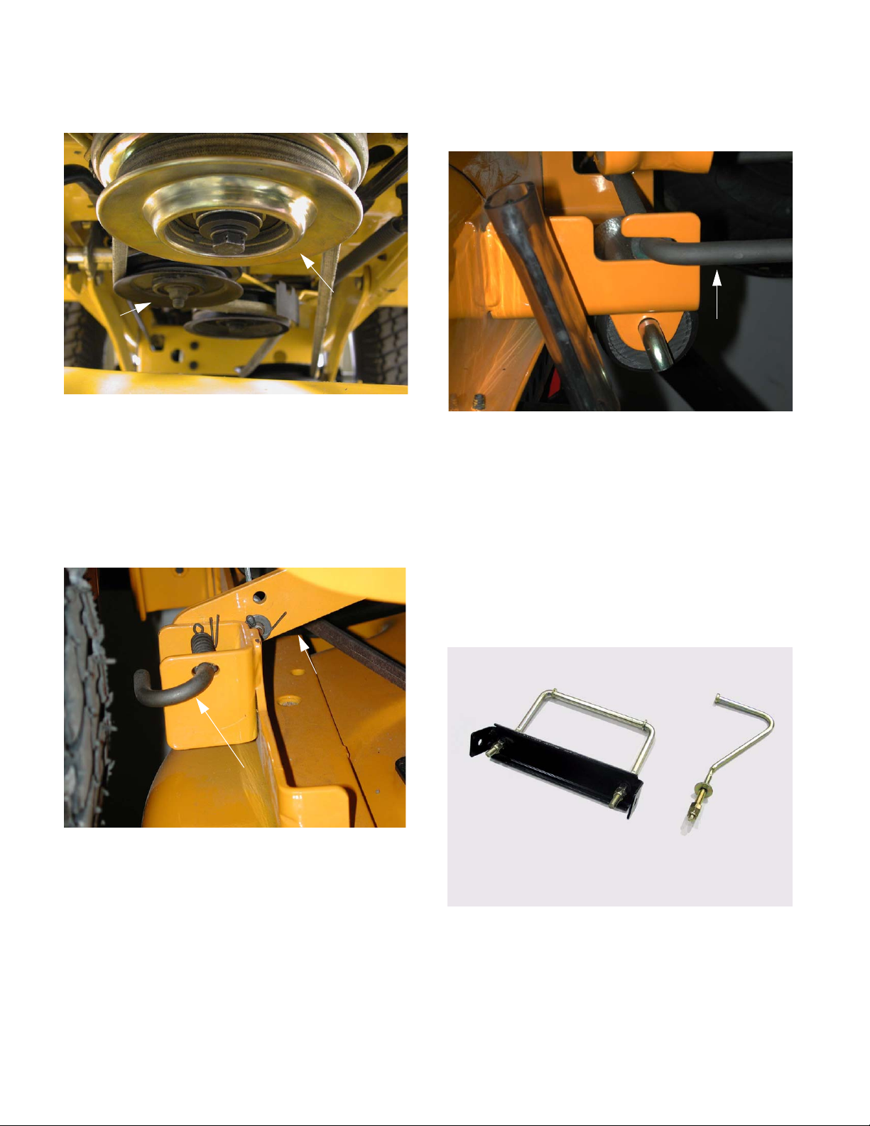
17.4. Pull the upper drive belt tensioner pulley rearwards to provide slack in the belt, and roll the
belt off of the tensioner pulley.
Tensioner pulley
See Figure 17.4.
16.22.Remove the nut and bolt holding the cruise cam
and/or the park brake locking plate.
16.23.Reassemble in reverse order.
CAUTION: Make sure the linkage rods are
routed properly before you swing the subframe
17. TRACTION DRIVE BELT REPLACEMENT: CVT
NOTE: There are two drive belts in the CVT sys-
tem. Because they work together on the variable
speed pulley, wear to one belt effects the perfor
mance of the other belt. It is strongly recommended that the belts be replaced as a set.
17.1. Remove the cutting deck from the tractor.
17.2. Tilt-up the seat and disconnect the battery
cables (ground cable first) using a 7/16” wrench.
-
Figure 17.4
17.5. Carefully release the tensioner pulley.
24
Page 29

Series 1000 and 1500
17.6. Using the slack created by taking the b elt off the
tensioner pulley, slip the belt off of the transaxle
input pulley and the upper sheave of the variable
speed pulley and remove the belt from the trac
tor. You may need to remove the transmission
input pulley to get enough clearance to remove
the belt.
Transmission input pulley
See Figure 17.6.
Figure 17.6
-
17.8. Lift the sliding center partition of the variable
speed pulley as far as it will go. This should pro
vide enough clearance to slip the lower belt off of
the variable speed pulley.
Variable speed pulley
17.9. Locate the double idler pulley bracket beneath
the tractor.
See Figure 17.9.
-
17.7. Loosen but do not remove the bracket that supports the variable speed pulley using a 1/2”
wrench.
NOTE: On 2004 and earlier CVT models, the
variable speed pulley was mounted directly to
the transaxle housing. On those tractors,
remove the variable speed pulley from the trac
tor using a pair of 9/16” wrenches.
See Figure 17.7.
Loosen these bolts
Figure 17.7
Double
idler
Figure 17.9
NOTE: This is the pair of pulleys that moves in
reaction to drive pedal input from the operator.
The further the pedal is depressed, the further
-
the bracket pivots, applying more tension to
the
belt.
17.10.Slip the lower drive belt off of the pulleys.
NOTE: On some 2004 and earlier models, it
may be necessary to loosen but not remove the
rear-most of the two pulleys (riding against the
flat side of the belt) to provide clearance to
remove the belt.
25
Page 30

Series 1000 and 1500
17.1 1.Disconnect the plug for the PT O clutch wire. It is
located on the right side of the tractor , just above
the opening in the frame that the wire passes
through to reach the PTO clutch.
See Figure 17.11.
PTO clutch plug
NOTE: On some models you may have to
remove the belt guide on the engine. Remo ve
the 1/2” bolt securing the belt guide to the frame
on the left hand side and slide the guide out of
the hole on the right hand side.
17.12.
Bolt
See Figure
Figure 17.11
17.12.Remove the bolt that holds the PTO clutch to the
crankshaft using a 5/8” wrench.
See Figure 17.12.
Figure 17.12
NOTE: If an impact wrench is unavailable it may
be necessary to use an improvised piston stop
or to hold the flywheel.
Figure 17.12
17.13.Carefully lower the PTO clutch and any associated hardware off of the crankshaft.
17.14.Lower the drive pulley far enough to allow the
belt to slip past the keepers that are stamped
into the frame. Slip the belt off of the pulley and
remove the pulley.
See Figure 17.14.
Figure 17.14
Stamped
belt
keepers
26
NOTE: Keep track of the position of any spacers
or washers that accompany the PTO clutch and
crankshaft pulley. Several different configura
tions have been used.
-
Page 31

Series 1000 and 1500
17.15.Remove the belt from the tractor.
NOTE: There were a small number of tractors
made using a CVT drive and a 2-speed
(L-H-N-R) G T transaxle. The belt must pass over
the center mounted gear selector on these mod
els for removal. Remove the knob from the gear
selector, and remove the shift gait from the
fender assembly to provide clearance.
17.16.Assembly notes:
• Install the belts by reversing the order of the
removal process.
• The engine drive pulley is installed on the drive
shaft with the key side facing down.
• Line up the key on the PTO clutch during assembly.
• There is a large flat washer that goes on top of
the PTO clutch during assembly.
• Torque the PT O clutch bolt during assembly.
• When installing the belt guide, make sure that it
passes through the cutout in the P TO clutch . this
acts as a anti-rotation bracket. Se e Figure 1 7.16.
• The tractor’s forward ground speed should vary
smoothly between 0 and 5.2 MPH when the
drive pedal is depressed progressively to the
end of it’s travel.
-
• It is normal for the cruise control to hold a mowing speed that is about 10% less than the 5.2
MPH transport speed.
• If the tractor performs as described, no adjustment is required.
18.2. Diagnosis: If the tractor does not move at all,
and the engine does not seem to be laboring as
the pedal is depressed, the issue may be in the
CVT belt system, the shift linkage leading to the
transaxle, or within the transaxle itself.
18.3. To isolate the CVT belt system:
• Turn-off the engine.
• Release the parking brake.
• Place the gear selector in any motion gear.
• Attempt to push the tractor.
• If the tractor rolls, examine the shift linkage.
• If the wheels lock when a gear is engaged, the
transaxle and shift linkage are not likely to be the
problem.
Cutout
Figure 17.16
18. DRIVE SYSTEM ADJUSTMENT: CVT
18.1. Make an operational test of the tractor:
• The tractor should not “creep” when the transmission is in gear and the drive pedal is not
depressed.
• On level ground, with the brake released, the
gear selector should slip smoothly into gear. It is
normal for gear engagement to be more difficult
on a grade, or with the brakes applied because it
is more difficult for the drive dogs to engage
under load or bind.
18.4. If the tractor does not move at all, and the
engine seems to be laboring as the pedal is
depressed, the issue may be in the brake, or
within the transaxle itself:
• Turn-off the engine.
• Release the parking brake.
• Place the gear selector in Neutral.
• Attempt to push the tractor.
• If the tractor rolls with difficulty, examine the
brakes as described in the “BRAKE ADJUSTMENT: CVT” section of this manual.
18.5. If the problem can be isolated to CVT belt drive
system, make a visual inspection of the CVT belt
drive system:
• Turn the engine off, and allow it to cool before
starting to work on the tractor.
• Remove the cutting deck.
• Lift the seat.
• Disconnect the battery cables, negative cable
first, using a 7/16” wrench
• Remove the battery hold-down.
27
Page 32

Series 1000 and 1500
• Remove the battery and battery tray from the
tractor.
18.6. Inspect the upper drive belt: See Figure 18.6.
Figure 18.6
• Is the upper drive belt correctly positioned on the
tensioner pulley , transaxle input shaf t pulley , an d
the upper sheave of the variable speed pulley?
loads (from torquing the nut) directly to the pul
ley, not the adaptor.
18.8. Repair any problems found. If the upper drive
belt is correct and in serviceable condition, rein
stall it. If the upper drive belt needs to be
replaced, the lower drive belt should be replaced
as well. Refer to the “TRACTION DRIVE BELT
REPLACEMENT” section of this manual.
18.9. Operate the drive pedal while observing the
movement of the components controlled by the
drive pedal.
See Figure 18.9.
Observe
movement
-
-
• Inspect the type and condition of the belt.
• Check the bearing on the tensioner pulley.
• Check the tensioner pulley arm: it should return
readily to static position under spring tension.
• The center partition of the variable speed pulley
should move up with light force and down under
it’s own weight.
18.7. The pulley on the transaxle input shaft should be
firmly attached.
• Early production tractors used a splined joint
between the pulley and the input shaft.
• Current production tractors carry the pulley on a
separate hub that fits over the splined shaft.
NOTE: The nut securing the pulley should be
tightened to a torque of 10-15 ft.-lbs using an 11/
16” wrench. Over-torquing the nut ma y shear the
input shaft. Replace the belleville washer
between the nut and the pulley if it is flattened.
NOTE: Some models used a special “fully finished” nut with an extended washer face. Do not
replace this nut with a standard nut unless a
washer is added between the nut and the pulley.
The washer must have a big enough O.D. to fit
over the star shape on the pulley adaptor, and
must be sufficiently thick to transfer compression
Figure 18.9
18.10.The double idler bracket should move with about
10 lbs pressure applied to the pedal, and retu rn
under spring pressure as the pedal is released.
See Figure 18.10.
Figure 18.10
28
Page 33

Series 1000 and 1500
18.11.The empty hole in the double idler bracket
should swing through an arc of 1 3/8” when 10
lbs. of force is applied to the drive pedal.
See Figure 18.11.
1 3/8” movement
Figure 18.11
18.12.If the measurement is not 1 3/8”, check the type
and condition of the lower drive belt. If the lower
drive belt is worn or incorrect, replace both drive
belts before adjusting the speed control. Refer to
the “TRACTION DRIVE BELT REPLACEMENT:
CVT” section of this manual.
18.13.If the belts are serviceable and correct, adjust
the length of the speed control rod to achieve the
correct double idler bracket travel as desc rib ed
in the following steps:
18.14.Loosen the jam nut that locks the speed control
rod into the rod-end joint at the double idler
bracket with a pair of 9/16” wrenches.
See Figure 18.14.
18.15.The forward end of the speed control rod connects to a pin attached to the speed contr ol
assembly.
NOTE: On 2005 production units you can
remove the nut on the ball joint and lift it out of
the idler bracket on an angle, then skip to step
15.16.
See Figure 18.15.
2005 production
Figure 18.15
• Early production models may have a hairpin clip
and washer adjacent to the cam plate that prevents the speed control linkage from moving
when the parking brake is applied.
• Remove the hairpin clip and washer if so
equipped.
• Disconnect the pin from the speed control
assembly using a pair of 9/16” wrenches.
18.16.Thread the rod in or out of the rod-end as
required to achieve the correct linkage travel.
Jam nut
Figure 18.14
18.17.When adjustment is complete:
• Secure the linkage and tighten any loosened
fasteners.
• Install the battery tray and battery.
• Test the operation of the drive system in a safe
area that is free of obstacles, hazards, and bystanders.
• After successful testing, install the cutting deck,
test all safety features, and return the mower to
service.
29
Page 34

Series 1000 and 1500
19. BRAKE ADJUSTMENT: CVT
19.1. On CVT-driven lawn and garden tractors, most
of the braking force is generated within the tran
saxle: when the drive pedal is released, the drive
ratio changes, slowing the tractor. The brake
brings the tractor to a complete stop, and func
tions as a parking brake.
19.2. When properly adjusted, the brake should do
two things: it should stop and hold the tractor
when applied, and it should not drag when
released.
19.3. To check that the brakes hold the tractor:
• Place the gear selector in Neutral.
• Set the parking brake.
• Attempt to push the tractor.
• The wheels should skid without rotating.
• If the brakes do not hold the tractor, the brake
needs to be adjusted or repaired.
19.4. To check that the brakes do not drag:
• Place the gear selector in Neutral.
• Release the parking brake.
• Attempt to push the tractor - it should move with
less than 20 lbs. of force. More force indicates
drag.
-
19.8. CVT-driven transaxles use a self locking nut on
the brake adjustment.
-
Figure 19.8
19.9. Insert a .013” feeler gauge between the brake
rotor and the outer brake pad. There should be
slight drag on the feeler gauge.
19.10.If the feeler gauge is too loose, or will not go in,
brake caliper adjustment is necessary.
19.1 1.A 1/2” wrench will turn the adjustment nut.
See Figure 19.11.
See Figure 19.8.
Lock nut
• If the brakes drag, they need to be adjusted or
repaired.
19.5. There is no linkage adjustment. All adjustment is
done at the brake caliper.
19.6. To reach the brake caliper, lift and safely support
the right rear corner of the tractor.
19.7. Remove the right rear wheel of the tractor using
a 3/4” socket.
Figure 19.11
19.12.Tighten the nut to reduce the clearance. Loosen
the nut to increase the clearance.
30
Page 35

Series 1000 and 1500
19.13.Check the movement of the brake arm:
• The brake arm should move forward as the
brake is applied.
• The return spring should draw the br ake arm
back against the spacer when the brakes are
released.
19.14.Visually check the thickness of the brake pads:
they are visible within the caliper.
19.15.Check the brake rotor:
• Confirm that the brake rotor floats on the splined
shaft by sliding it in and out with light finger pressure.
• If it binds on the shaft it may cause brake drag
and reduced holding performance.
• A rotor that has been dragging will frequently be
discolored by the heat (blue).
19.16.If the brakes are dragging or worn, or if the rotor
needs to be removed from the shaft, r emove the
two bolts that hold the caliper to the transaxl e
using a 3/8” wrench.
See Figure 19.16.
19.17.Remove the caliper from the transaxle. The
brake actuator arm can now be unhooked from
the spring that connects it to the linkage.
Figure 19.17.
Figure 19.17
19.18.The rotor should slip-of f of th e sp lined sh aft, providing access to the fixed brake pad.
See Figure 19.18.
See
Caliper
2 Bolts
Fixed brake pad
Figure 19.16
Figure 19.18
31
Page 36

Series 1000 and 1500
19.19.A crease in the brake arm acts as a cam. At rest,
the ends of the two pins ride in the peak of the
crease:
• The brake arm pivots on a square-headed stud.
• The two pins are forced against the backing
plate when force is applied to the arm.
• The backing plate rides between the pins and
the pad, to prevent the pins from damaging the
brake pad.
See Figure 19.19.
Figure 19.19
20. SERVICING THE BRAKE PEDAL SHAFT BUSH-
INGS:
• If there is insufficient travel in the linkage to fully
apply the brakes, a simple visual inspection
should identify the cause.
20.1. Confirm that the brake pedal is firmly att ached to
the pedal shaft.
20.2. Remove the cutting deck to re ac h th e brake
pedal shaft, bushings, and bracket.
See Figure 20.1.
Brake Pedal
Figure 20.1
19.20.Replace the pads if they are worn. They frequently last many years unless the brakes have
been dragging.
19.21.Be sure the pin bores are clear of dirt and corrosion: either may cause the pins to bind and the
brakes to drag.
19.22.On assembly, apply a small amount of dry
graphite lubricant to the pins and the spots on
the brake arm that they contact. Do not allow
any lubricant to get on the brake pad.
19.23.Install the brake caliper, tightening the two nuts
to 7 to 10 ft.-lbs., then check and adjust the padto-rotor clearance.
19.24.Install the rear wheel, tightening the lug nuts to a
torque of 350 to 500 In.-lbs. Lower the tractor to
the ground.
19.25.After any brake service is performed, test the
brakes as described in steps 24.2 through 24.4,
then test-drive the tractor in a safe area that is
free of hazards, obstacles, and by-standers
before returning the tractor to service.
20.3. Check for excessive play in the bushings.
Replace them if they are worn.
NOTE: It is suggested that if any of these bushings need to be replaced, replace all of the pedal
shaft bushings at this time. The speed control
pedal shaft bushings are replaced in a similar
manner.
32
Page 37

Series 1000 and 1500
20.4. The inboard brake pedal shaft bushing can be
removed by removing the cotter pin and washer
that secure it.
20.5. The brake rod must be disconnected to remove
the outboard brake pedal shaft bushing.
Remove and discard the cotter pin that holds the
brake rod to the brake pedal shaft.
See Figure 20.5.
See Figure 20.4.
Bushing
Figure 20.4
Brake rod
20.6. Press the brake pedal shaft as far outward as
possible, and pry the worn bushing out of the
bracket.
NOTE: A pair of vice-grips and a plate can be
used to press the end of the shaft flush with the
edge of the bracket
NOTE: The inner bushing is a hex flange bushing. The outer bushing is similar, but has one
open side. The “tooth” in the top facet of the
bracket that supports the bushing registers in
open side of the bushing.
See Figure 20.6.
Figure 20.6
Figure 20.5
20.7. Clean any corrosion or dirt from the surfaces
where the pedal shaft contacts the bushing, and
slip the new bushings into place.
20.7.
Figure 20.7
See Figure
33
Page 38

Series 1000 and 1500
NOTE: Lubrication with grease may accelerate
bushing wear. If lubrication is applied it should
be in dry form such as graphite or PTFE (Teflon).
21.2. Remove the battery hold down, battery and battery tray from the unit. See Figure 21.2.
20.8. Secure the inner bushing with a new cotter pin
and the flat washer that was previously
removed.
20.9. Move the pedal through it’s range of travel to
check for binding. If binding is encountered:
• Bind in just a portion of the travel may be caused
by a bent pedal shaft.
• Constant bind is likely to be caused by a bent
bracket.
• Also check for interference between the parking
brake and cruise control interlocks.
20.10.Correct any binding condition.
20.11.Connect the brake rod to the brake pedal shaft,
and secure it with a new cotter pin.
20.12. After any brake service is performed, test the
brakes as described in steps 14.2 through 14.4,
then test-drive the tractor in a safe area that is
free of hazards, obstacles, and by-standers
before returning the tractor to service.
21. TRANSAXLE REPLACEMENT: CVT
Battery hold down
Figure 21.2
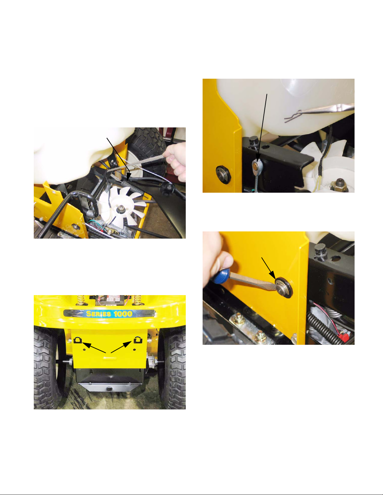
21.3. Take tension off of the transmission belt idler
and remove the belt from around the idler pulley.
See Figure 21.3.
Idler pulley
• The single speed transaxles used in our CVT
riders has evolved over the years. Internals ha ve
changed. Some have had the Variable Speed
Pulley integrated into the transaxle. If you are
replacing a transaxle it is very important to carefully match the transmission part numbers
between the old and new. A part number on the
transmission case might be the number of the
case half. Visually compare the IPL drawing with
the actual transaxle to assure a match .
• Before condemning a transaxle, check to make
sure the brake is not locking up the transaxle.
• Check the drive belts for damage or wear and
make sure they are the correct belts and ar e not
the cause of drive problems.
• When replacing a transaxle within the warranty
period, we have a like-kind exchange program.
• Out of warranty transaxles can be serviced.
21.1. Disconnect the battery cables (negative first and
then positive).
Figure 21.3
34
Page 39

Series 1000 and 1500
21.4. Using a 7/8 socket and extension, remover the
nut securing the transmission pulley to the trans
mission. See Figure 21.4.
Transmission pulley
Figure 21.4
21.5. Remove the pulley from the unit.
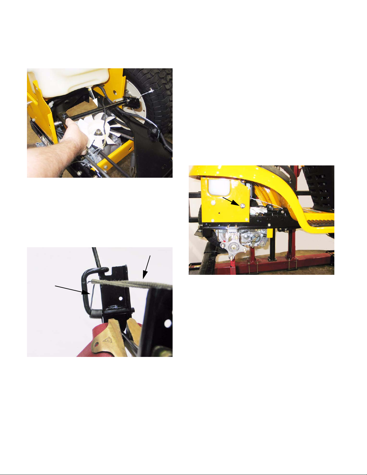
21.6. Support the frame of the unit to allow removal of
both rear wheels.
See Figure 21.6.
21.7. Disconnect the brake linkage where it connects
-
to the brake spring.
Brake linkageBrake linkage
21.8. Use white-out to mark the position of the ferrule
on the transmission shift rod.
21.9. Remove the hairpin clip securing the transmission shift rod to the transmission. See Figure
21.9.
See Figure 21.7.
Figure 21.7
Figure 21.6
NOTE: Leave room under the rider to allow low-
ering the transaxle from the unit.
Hairpin clip
Figure 21.9
21.10.Using a 1/2” socket, remove the two hex screws
securing the front of the transmission housing to
the transmission support bracket.
21.9.
21.11.Support the transmission from below.
35
See Figure
Page 40

Series 1000 and 1500
21.12.Using a 1/2” socket and 1/2” wrench, remove the
four hex nuts securing the transmission to the
frame.
See Figure 21.12.
Nuts
Figure 21.12
CAUTION: The transmission must be supported
during removal of the bolts. Use a helper if nec
essary.
22. TRANSAXLE SERVICE AND INTERNALS: CVT
• Transaxles needing service within the warranty
period qualify for like-kind exchange.
• If you are servicing transaxle internals, keep in
mind that different transaxles/components have
been used over the years.
• Carefully compare the transaxle with the illustrated parts list when ordering components.
23. TRACTION DRIVE BELT REPLACEMENT: HYDROSTATIC LT
23.1. Turn-off the engine and allow all parts to cool
before beginning work.
23.2. Remove the cutting deck.
23.3. Identify and unplug the wires leading to the elec-
-
tric PTO clutch. See Figure 23.3.
21.13.Lower the transmission from the rider. See Figure 21.13.
Figure 21.13
NOTE: There is a backing plate on the top of th e
frame. There may be a spacer between the
frame and the transmission housing.
21.14.Reassemble in the reverse order of disassembly.
PTO clutch wires
Figure 23.3
NOTE: If it appears that the drive belts a re worn,
we recommend replacing both of them when
servicing the transaxle. Use original OEM belts
to assure proper operation of the rider.
36
Page 41

Series 1000 and 1500
23.4. Remove the electric PTO clutch from the engi ne
crankshaft using a 5/8” wrench.
Figure 23.4
NOTE: Lower the clutch carefully, keeping track
of the hardware on the crankshaft. There are
variations between engines, clutches and years:
• Spacer s above or below the traction drive pulley.
• Integral or separate key on traction drive pulley.
• Different PTO clutch anti-rotation brackets.
23.5. Slip the belt off of the single fixed idler.
See Figure 23.5.
See Figure 23.4.
5/8” Head bolt
23.6. Carefully release the spring that maintains tension on the double idler bracket using a length of
starter rope or an appropriate tool.
See Figure 23.6.
Figure 23.6
23.7. Slip the drive belt from between the double idler
pulleys.
NOTE: On some early models, the rear-most
pulley (rides against V side of belt) was large
enough that the double idler bracket acted as a
belt keeper. On those models, it is necessary to
loosen the nut and bolt that secure that pulley to
the bracket in order to slip the belt past th e edge
of the bracket.
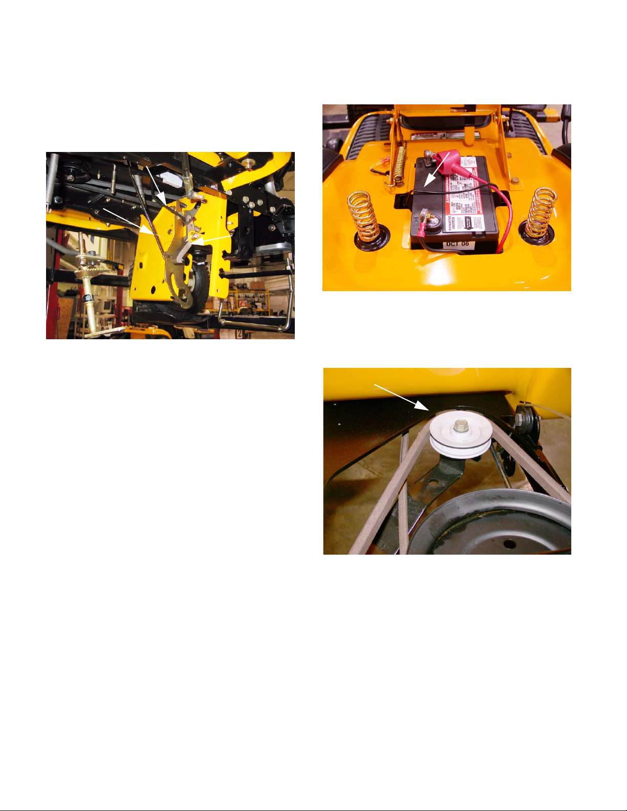
Figure 23.5
NOTE: Pulleys may be steel or plastic, depend-
ing on when the tractor was built.
37
Page 42

Series 1000 and 1500
23.8. Slip the crankshaft pulley down far enough to get
the belt off of the pulley, and remove the belt
from the crankshaft.
Stamped Belt Guards
NOTE: Belt keepers that are part of the tractor
frame prevent the belt from being removed with
out lowering the pulley.
NOTE: The pulley may be removed from the
crankshaft at the discretion of the technician.
• If there is a spacer above the pulley, the end with
the radiused inside edge mates with the radiused step on the crankshaft.
• If one end of the pulley has a radiused inside
edge, that is the end that mates with the radiused step on the crankshaft.
23.9. Carefully work the belt over the top of the cooling
fan on the transaxle, and remove it from the trac
tor. See Figure 23.9.
See Figure 23.8.
Figure 23.8
23.10.The belt for the G.T. models of the 1500 Series
line is Kevlar wrapped. Substituting the polywrapped belt used on the L.T. models is not rec
ommended, but the Kevlar belt is an acceptable
premium upgrade for the L.T. tractors.
See Figure 23.10.
-
23.11.If the traction drive belt failed prematurely, identify the cause of it’s demise before installing a
replacement. Check the condition of all of the
idler pulleys.
23.12.The fixed idler pulley can be removed from later
models using a single 1/2” wrench. The bolt that
holds the fixed idler to earlier models threads
into a 3/8” nut above the tractor frame. The bolt
can be removed from the nut using a pair of
9/16” wrenches without removing the fenders.
-
See Figure 23.12.
Kevlar wrapped belt
Figure 23.10
-
Figure 23.9
Fixed idler
Figure 23.12
38
Page 43

Series 1000 and 1500
23.13.The double idler pivot bracket is held to the
frame by the same bolt that holds the fore-most
of the two pulleys. The rear pulley can be easily
removed from the bracket. It is necessary to take
the fenders off to remove the front pulley or the
bracket itself.
23.14.Install the drive belt by reversing the order of the
removal process.
• Apply anti-seize compound to the crankshaft
before installing the PTO clutch.
• Tighten the crankshaft bolt to a torque of 38-50
ft.-lbs. on assembly.
• Test the drive system and all tractor safety features in a clear area that is free of hazards and
by standers before returning the tractor to service.
24. DRIVE SYSTEM ADJUSTMENT: HYDROSTATIC LT
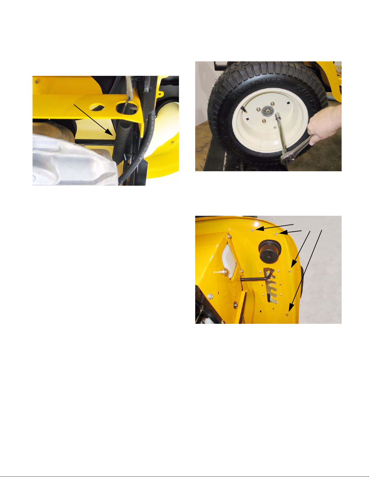
24.1. The relief valve is operated using a small rod
that is visible at the bottom right corner of the
rear of the tractor frame.
See Figure 24.1.
24.3. There is no adjustment to the relief valve, but full
travel of the linkage should be checked if the
drive system is losing power or ground speed.
See Figure 24.3.
Relief valve linkage
Figure 24.3
24.4. Symptoms of a linkage that is out of adjustment
include:
Relief valve rod
Figure 24.1
24.2. Pulling the rod out and locking it in the upper
portion of the keyhole enables the tractor to be
pushed, but disables the hydraulics of the drive
system by opening a valve that releases the
hydraulic pressure from the motor circuit.
• Low ground speed in either direction with no
unusual noises from the transaxle. One possible
cause for low ground speed is a linkage that
does not transfer all of the pedal travel to the
input arm on the transaxle.
• “Creeping” when the transaxle is in neutral
position.
• Whining or growling when the tractor is in Neutral with the brake applied.
• The creeping and whining symptoms usually
accompany one-another, indicating that the linkage is not properly centered around Neutral.
• Low ground speed in one direction only (For ward or Reverse) may accompany whining,
growling or creeping in Neutral if the linkage is
out of adjustment.
• Low ground speed, accompanied by excessive
noise is likely to be an internal problem or a
brake that is dragging or out of adjustment.
24.5. Begin linkage adjustment by inspecting the linkage. Linkages on equipment that has been in the
field are usually out of adjustment becaus e th e
linkage is binding, worn, bent, or tampered with.
24.6. Replace any worn or damaged part s before
adjusting the linkage.
39
Page 44

Series 1000 and 1500
24.7. Turn-off the engine and allow it to cool before
starting to work on the tractor. To gain access to
the control linkage, perform the following three
steps:
24.8. Remove the cutting deck.
24.9. Lift and safely support the rear of the tractor.
24.10.Remove the rear wheels using a 3/4” wrench.
24.11.Move the control pedal through it’s range of
travel (with the parking brake released) and look
for the following conditions that will cause loss of
linkage motion:
• Pedal loose on the pedal shaft.
• Loose arm that connects the pedal shaft to the
control rod.
• Worn bushings supporting the pedal shaft.
• Worn ferrule or an elongated hole where ferrule
connects to pedal shaft.
24.12.Disconnect the control rod from the pedal shaft
by removing the cotter pin that secures the
adjustable ferrule on the rod to the shaft.
See Figure 24.12.
24.15.Set the parking brake, and remove the drive
pedal using a T-40 driver.
T-40 Screws
Figure 24.15
24.16.Remove and discard the cotter p ins that hold the
inboard bushing in place on both the speed con
trol assembly and the brake control assembly.
See Figure 24.16.
See Figure 24.15.
-
Adjustable
ferrule
Figure 24.12
24.13.Confirm that the pedal shaft moves freely in the
bushings, and does not bind.
24.14.Worn pedal shaft bushings are easily replaced
using the following 5 steps.
NOTE: It is recommended to replace all four
bushings at the same time.
Cotter pins
Figure 24.16
40
Page 45

Series 1000 and 1500
24.17.Remove the washers and inboard bushings from
both shafts.
24.18.Slide both shafts outboard far enough to create
clearance to remove the outer shaft bushings,
and remove the bushings.
See Figure 24.17.
Figure 24.17
See Figure 24.18.
24.21.Install the drive pedal, tightening the screw that
secures it to a torque of 250 in-lbs.
24.22.Move the pedal through it’s range of travel to
check for bind. If binding is encountered:
• Bind in a portion of the travel may be caused by
a bent pedal shaft.
• Constant bind is likely to be caused by a bent
bracket.
• Also check for interference between the park
brake and cruise control interlocks.
24.23.Correct any source of binding. The pedal shaf t is
easily removed at this point. The bracket may be
straightened if damage is minor.
24.24.Confirm that no unsafe conditions will arise from
starting the engine.
24.25.Start the engine, and operate it at top-no-load
speed. Note the operation of the transaxle with
the pedal linkage disconnected: An assistant
may be required.
• Growling or whining with brake applied indicates
that the input arm on the transaxle needs adjustment.
Figure 24.18
NOTE: The inner bushings are hex flange bush-
ings. The outer bushings are similar, but are
open on one side. The “tooth” in the top facet of
the bracket that supports the bushing registers in
the open side of each bushing.
24.19.Clean any corrosion or dirt from the surfaces
where the pedal shaft contacts the bushing, and
slip the new bushings into place.
NOTE: Lubrication with grease may accelerate
busing wear. If lubrication is applied it should be
in dry form such as graphite or PTFE (Teflon).
• Movement of the left rear whee l or the right drive
hub with the brake released indicates that the
input arm on the transaxle needs adjustment.
• With the hydro control rod disconnected from the
pedal shaft, the input arm on the transaxle
should return to Neutral.
24.26.If the transaxle does not return properly to neutral, adjust the input arm to correct the issue,
then proceed with the following step. Review the
next section for procedures.
24.27.If the transaxle returns properly to neutral:
• Adjust (if necessary) and reconnect the hydro
control rod.
• Install the right rear wheel on the tractor, tightening the lug nuts to a torque of 350 - 500 in.-lbs.
• Lower the tractor to the ground and test the
operation of the drive system in a safe area that
is free of hazards, obstacles, and by-standers.
• Install the cutting deck, test all safety features,
and return the tractor to service if everything
works properly.
24.20.Secure the pedal shafts with new cotter pins and
previously removed washers.
41
Page 46

Series 1000 and 1500
25. HYDRO CONTROL ROD ADJUSTMENT
• If the unit “creeps” in the neutral position, one of
two things may have happened: 1. The hydro
control rod has been bent, causing the unit to
creep or 2. The neutral position adjustm ent on
the hydro has changed.
25.1. Set the parking brake. The cam in the parking
brake mechanism will lock the pin on the pedal
shaft into neutral.
25.2. There should now be no tension on the hydro
control rod.If there appears to be tension, look
for a damaged or bent rod.
25.3. Remove the cotter pin securing the ferrule to the
pivot arm on the pedal shaft.
See Figure 25.1.
Pin locked into neutral
Figure 25.1
25.5. If there is, thread the ferrule up or down the
length of the hydro control rod until the post is
centered in the hole that it fits into. At this point,
the transaxle and the linkage should both be
synchronized in neutral.
Adjust ferrule
Figure 25.5
25.6. Secure the ferrule to the arm on the pedal shaft
using a new cotter pin.
25.7. T est drive the unit to see if it still creep s. If it does
you will have to adjust the input arm on the
hydro: Confirm that the roller on the return arm
draws fully into the valley in the cam surface on
the front of the input arm.
See Figure 25.5.
See Figure 25.7.
25.4. Remove the ferrule from the hole in the
arm.There should be no tension on the rod
where it connects to the pivot arm.
Roller
Figure 25.7
42
Page 47

Series 1000 and 1500
25.8. As the hydro control rod moves back on the
input arm, it first moves a ground contact against
the reverse safety switch.
Reverse switch
Figure 25.8
25.9. After the switch contacts the ground, the hydro
control rod reaches the end of the lost-motion
slot, and begins to push the arm forward, to the
reverse position. Excessive lost motion will
result in loss of ground speed in reverse.
25.10.As the hydro control rod is pushed rearward, it
draws the cam (front) surface of the input arm
upward, forcing the neutral return arm forward,
applying more tension to the return spring.
See Figure 25.10.
See Figure 25.8.
• If the roller is moved lower, the input arm will
move in the direction that causes reverse drive.
25.12.The roller is moved up or down by rotating the
house-shaped eccentric that the neutral return
arm pivots on.
25.13.Loosen the eccentric using a 1/4” Allen wrench,
and rotate it to adjust the roller up or down, as
required to center the input arm in neutral.
25.14.Tighten the socket head cap screw to lock the
adjustment, and check to confirm that the adjust
ment is correct.
25.15.After confirming that the transaxle is correctly
adjusted:
See Figure 25.12.
Figure 25.12
-
Return spring
Figure 25.10
25.11.The point that the neutral return ar m dr aws the
input arm to is determined by the position of the
roller on the neutral return arm:
• If the roller is moved higher, the input arm will
move in the direction that causes forward drive.
• Adjust and reconnect the hydro control rod if it
has been removed.
• Install the right rear wheel on the tractor if it was
removed.
• Test the operation of the drive system in a safe
area that is free of hazards, obstacles, and bystanders.
• Install the cutting deck, test all safety features,
and return the tractor to service if everything
works properly.
26. BRAKES AND BRAKE ADJUSTMENT: HYDROSTATIC LT
26.1. On hydrostatic garden tractors, most of th e bra king force is generated within the transaxle: when
in Neutral, with the brakes released, the tractor
will still be very difficult to push unless the relief
valve has been opened. The brake functions
mainly as a parking brake.
43
Page 48

Series 1000 and 1500
26.2. When properly adjusted, the brake should do
two things: it should stop and hold the tractor
when applied, and it should not drag when
released.
26.3. To check that the brakes hold the tractor:
• Open the relief valve.
• Set the parking brake.
• Attempt to push the tractor.
• The wheels should skid without rotating.
• If the brakes do not hold the tractor, the adjustment needs to be tightened or the brakes need
to be repaired.
26.4. To check that the brakes do not drag:
• Open the relief valve.
• Release the parking brake.
• Attempt to push the tractor - it should move with
about 40 lbs of force. More force indicates drag.
• If the brakes drag, they need to be adjusted or
repaired.
26.9. Insert a .015” feeler gauge between the brake
rotor and the outer brake pad. There should be
slight drag on the feeler gauge.
26.10.If the feeler gauge is too loose, or will not go in,
brake caliper adjustment is necessary.
26.11.Remove and discard the cotter pin. A 9/16”
wrench will turn the adjustment nut.
26.11.
See Figure
26.5. There is no linkage adjustment. All adjustment is
done at the brake caliper.
26.6. To reach the brake caliper, lift and safely support
the right rear corner of the tractor.
26.7. Remove the right rear wheel of the tractor using
a 3/4” wrench.
26.8. Hydro-Gear transaxles use a castle nut locked
with a cotter pin.
See Figure 26.8.
Castle nut
Figure 26.11
26.12.Tighten the nut to reduce the clearance. Loosen
the nut to increase the clearance.
26.13.Check the movement of the brake arm:
• The brake arm should move forward as the
brake is applied.
• The return spring should draw the brak e ar m
back against the spacer when the brakes are
released.
26.14.Visually check the thickness of the brake pads:
they are visible within the caliper.
26.15.Check the brake rotor:
• Confirm that the brake rotor floats on the splined
shaft by sliding it in and out with light finger pressure.
• If it binds on the shaft it may cause brake drag
and reduced holding performance.
• A rotor that has been dragging will frequently be
discolored by the heat (blue).
Figure 26.8
44
Page 49

Series 1000 and 1500
26.16.If the brakes are dragging or worn, or if the rotor
needs to be removed from the shaft disconnect
the brake return spring where it attaches to the
transmission housing.
Brake return spring
Figure 26.16
26.17.Using a suitable tool, remove the large hydro
return spring where it attaches to the hydro arm.
26.18.Using a 7/16” wrench, remove the two bolts that
hold the caliper to the transaxle.
26.16.
See Figure 26.16.
See Figure
26.20.In order to remove the rotor and gain access to
the fixed brake pad you will have to pry the
retaining clip securing the hydro relief arm to the
hydro relief valve shaft.
Retaining clip
Figure 26.20
NOTE: During re-assembly you will have to
replace the retaining clip with a new one.
26.21.The brake rotor should slide-off of the splined
shaft, providing access to the fixed brake pad.
See Figure 26.21.
See Figure 26.20.
26.19.Once the caliper is removed form the transaxle,
the brake arm can be unhooked from the spr i ng
that connects it to the brake linkage.
26.19.
Figure 26.19
See Figure
Figure 26.21
45
Page 50

Series 1000 and 1500
26.22.The crease in the brake arm acts as a cam:
See Figure 26.22.
Figure 26.22
• The brake arm pivots on a square-headed stud.
• The two pins are forced against the backing
plate when force is applied to the arm.
• The backing plate rides between the pins and
the pad, to prevent the pins form working
through the brake pad.
brakes, a simple visual inspection should identify
the cause.
26.31.Confirm that the brake pedal is firmly att ached to
the pedal shaft.
Brake Pedal
26.32.Remove the cutting deck to inspect the brake
pedal shaft, bushings, and bracket.
26.33.Check for excessive play in the bushings.
Replace them if they are worn.
See Figure 26.31.
Figure 26.31
26.23.Replace the pads if they are worn. They frequently last many years unless the brakes have
been dragging.
26.24.Be sure the pin bores are clear of dirt and corrosion: either may cause the pins to bind and the
brakes to drag.
26.25.On assembly, apply a sparing amount of dry
graphite lubricant to the pins and the spots on
the brake arm that they contact. Do not allow
any lubricant to get on the brake pad.
26.26.Install the brake caliper, tightening the two bolts
to 7 to 10 ft.-lbs., then check and adjust the padto-rotor clearance.
26.27.Lock the adjustment nut with a new cotter pin.
26.28.Install the rear wheel, tightening the lug nuts to a
torque of 350 to 500 in.-lbs. Lower the tractor to
the ground.
26.29.After any brake service is performed, test the
brakes as described in steps 23.3 - 23.4 then
test-drive the tractor in a safe area that is free of
hazards, obstacles, and by-standers befo re
returning the tractor to service.
See Figure 26.11.
27. PEDAL BUSHING REPLACEMENT
27.1. If any of the pedal bushings are worn, replace all
the bushings.
27.2. Remove the brake pedal where it connects to
the brake pedal shaft.
26.30.If the brake is adjusted correctly and ther e is
insufficient travel in the linkage to fully apply the
46
Page 51

Series 1000 and 1500
27.3. Remove and discard both cotter pins that secur e
the brake pedal shaft and the hydro drive pedal
shaft to the frame.
Cotter pins
27.4. Remove the large washers and inner bushings
from each shaft.
27.5. Press both shafts as far outward as possible,
and pry the worn bushings out of the bracket.
See Figure 27.5.
See Figure 27.3.
Figure 27.3
27.6. Clean any corrosion or dirt from the surfaces
where the pedal shafts contact the bushings,
and slip the new bushings into place.
See Figure 27.6.
Clean
Figure 27.6
NOTE: Lubrication with grease may accelerate
bushing wear. If lubrication is applied it should
be in dry form such as graphite or PTFE (Teflon).
27.7. Secure the inner bushings with new cotter pins
and the flat washers that were previously
removed.
Figure 27.5
NOTE: A pair of vice-grips and a plate can be
used to press the end of the shaft flush with the
edge of the bracket to aid removal of the bush
ings.
NOTE: The inner bushing is a hex flange bushing. The outer bushing is similar, but has one
open side. The “tooth” in the top facet of the
bracket that supports the bushing registers in
open side of the bushing.
-
27.8. Move the pedal through it’s range of travel to
check for bind. If binding is encountered:
• Bind in a portion if the travel may be caused by a
bent pedal shaft.
• Constant bind is likely to be caused by a bent
bracket.
• Also check for interference between the park
brake and cruise control interlocks.
27.9. Correct any binding condition.
27.10.Connect the brake rod to the br ak e pe da l s ha ft,
and secure it with a new cotter pin.
27.11. After any brake service is performed, test the
brakes as described in Section 23, then testdrive the tractor in a safe area that is free of haz
ards, obstacles, and by-standers before returning the tractor to service.
28. TRANSAXLE SERVICE AND MAINTENANCE: HYDROSTATIC LT
28.1. In normal use, the transaxle should last the life
of the tractor with minimal maintenance.
-
47
Page 52

Series 1000 and 1500
28.2. Because the transaxle dissipates heat through
air-cooling of the housing, it must be kept clean
of dirt and debris, and the cooling fan should be
replaced immediately if damaged.
28.3. Cleanliness is vitally important when doing any
service work that might expose the fluid or inter
nal parts to any form of contamination. Clean
thoroughly around any fittings, parts, or seals
that are to be removed prior to removal.
28.4. Pressure washing is not recomm e nd ed , an d
may contaminate the transmission fluid. Dam
age caused by contaminated fluid is not war rantable.
28.5. Before commencing internal repairs, eliminate
all possible external performance issues:
• Dragging brake
• Maladjusted linkage
• Partially open relief valve
• Slipping traction drive belt/ low engine speed
28.6. The transaxle contains .600 to .632 gal of 20W50 motor oil with an API classification of SH/CD.
-
will fill the over-flow reservoir, but will not add to
the level of fluid in the transaxle.
NOTE: This oil (fluid) should not have to be
changed in the normal service life of the tran
saxle unless it develops a leak or becomes con-
-
taminated.
28.8. If the transaxle develops a leak, identify and
repair the leak to prevent further damage.
28.9. To drain the oil, Hydro-Gear recommends
removal of the transaxle, for draining through the
fill port.
28.10.A new addition to the transaxle is a drain plug.
Depending on the date of manufacture, this plug
may or may not be present.
Drain plug
See Figure 28.10.
-
28.7. Fill through the port at the top of the transaxle.
Fluid will spill into the plastic over-flow reservoir
as the fluid capacity is reached.
28.7.
Over-flow
reservoir
Figure 28.7
NOTE: Some transaxles may be painted black,
depending on the year of production.
NOTE: The plastic over-flow reservoir has a
plastic vent cap at the top. This is strictly a vent
cap. Attempting to add fluid through the vent cap
See Figure
Fill port
Figure 28.10
28.11.Any time the fluid has been drained from a
hydrostatic transaxle, the air should be purged
from the system on initial start-up.
28.12.T o purge the air from the hydraulic system in the
transaxle:
• Open the relief valve.
• Start the engine.
• Slowly cycle the drive pedal from full speed forward to full speed reverse 5 or 6 times, taking
about 10 seconds to complete a single cycle.
• Stop the engine and check the fluid level at the
fluid level port near the back of the right side
axle housing. The plug can be removed with a
1/4” Allen wrench. Top-up as necessary.
• Close the relief valve.
• Start the engine.
48
Page 53

Series 1000 and 1500
• Repeat as necessary until the transaxle operates normally.
28.13.Any service beyond fluid change requires
removal substantial disassembly of the tran
saxle. Refer to Hydro-Gear manual BLN-52261
for complete repair instructions.
29. TRANSAXLE REPLACEMENT: HYDROSTATIC LT
29.1. Warrantable failures on Cub Cadet tractors are
to be repaired by replacing the transaxle. Failed,
warrantable transaxles will be called-back
through Cub Cadet’s vendor recovery system.
Failures of Hydro-Gear transaxles are rare.
29.2. Outside of warranty , Hydro-Gear transaxles may
be repaired or replaced at the discretion of the
customer and servicing dealer.
29.3. Before condemning a transaxle, eliminate all
possible external performance issues:
• Dragging brake
• Maladjusted linkage
• Partially open relief valve
• Slipping traction drive belt/ low engine speed
29.4. Remove the cutting deck to gain access to the
linkages that will need to be disconnected.
29.5. Lift and safely support the rear of the tractor.
29.6. Remove the rear hub caps, then the rear wheels
using a 3/4” wrench.
29.7. Remove the rear hub caps, then the rear wheels
using a 3/4” wrench.
See Figure 29.7.
-
29.8. Disconnect the front of the bra ke ro d fr om the
brake pedal shaft by removing the cotter pin,
and pulling the “L” at the forward end of the rod
out of the hole in the brake pedal shaft.
See Figure 29.8.
Brake rod
Figure 29.8
29.9. Disconnect the ferrule at the forward end of the
speed control rod from the speed control pedal
shaft in similar fashion.
29.10.Unplug the wire from the reverse safety switch
(Red wire w/black trace on Rev-Tek equipped
models, Yellow wire w/black trace on others).
29.11.Disconnect the ground wire from the transaxle
using a 3/8” wrench.
29.12.Remove the fan from the input pulley on the
transaxle using 5/16” wrench.
See Figure 29.12.
Figure 29.7
Figure 29.12
49
Page 54

Series 1000 and 1500
29.13.Draw the traction drive belt off of the fixed idler
pulley to create slack, then work the belt off of
the double idler pulleys, similar to the method
described in the “TRACTION DRIVE BELT:
HYDROSTATIC LT” section of this manual.
29.14.Slip the belt off of the input pulley.
See Figure 34.15.
Figure 29.14
29.17.Disconnect the deck lift assist spring that hooks
to the left side of the transaxle torque bracket
using a length of starter rope or a spring removal
tool.
A piece of rope
Figure 29.17
29.18.Disconnect the heavy return spring that pulls the
control arm toward the rear of the tractor.
See Figure 29.18.
See Figure 29.17.
29.15.Disconnect the hydro relief rod from the relief
valve by unhooking the extension spring that
joins the rod to the arm that operates the valve.
See Figure 29.15.
Figure 29.15
29.16.Maneuver the rod to a position where it will not
interfere with nor be damaged by the removal of
the transaxle.
Spring
Figure 29.18
50
Page 55

Series 1000 and 1500
29.19.A length of starter rope is best used to disconnect the front of the spring from the control arm.
pass the rope over the torque bracket, an d draw
downward on the rope to avoid destabilizing the
tractor.
29.20.Support the transaxle with a hydraulic jack.
29.21.Remove the two screws that connect the stabilizer bracket to the frame using a 1/2” wrench.
See Figure 29.21.
See Figure 29.19.
Figure 29.19
29.23.Carefully lower the transaxle to the ground, complete with torque bracket, brake rod, and hydro
control rod.
29.24.Installation notes are as follows:
29.25.Fill the transaxle with fluid before installing it in
the tractor. Some dealers have devised ways to
manually drive the input shaft and purge the air
from the drive system on the bench, prior to
installation.
See Figure 29.23.
Figure 29.23
Stabilizer
bracket
screw
Figure 29.21
29.22.Remove the pair of nuts and bolts that fasten
each axle housing of the transaxle to the tractor
frame. Use a pair of 1/2” wrenches.
NOTE: The bolts pass through a steel reinforcement (sister) plate above the lip on the tractor
frame, and an aluminum spacer that fits be tween
the frame and the axle housing.
29.26.If bench purging is not available, follow the purging instructions described in the “TRANSAXLE
SERVICE AND MAINTENANCE: HYDRO
ST ATIC GT” section of this manual after the tran saxle is installed.
29.27.Reverse the removal process to install the transaxle.
• Tighten the screws to the torque bracket to a
torque of: 35 ft.-lbs.
• Tighten the bolts holding the axle housings to
the frame to a torque of: 250 in-lbs.
• Tighten the screws holding the fan to the pulley
to a torque of: 30-35 in-lbs.
• Tighten the lug nuts to a torque of:
29.28.Test run the tractor in a safe area that is free of
hazards, obstacles, and bystanders to confirm
correct operation and adjustment before install
ing the cutting deck. Make any necessary adjustments.
29.29.Test run the tractor in a safe are that is free of
obstacles, hazards, and bystanders af ter the cut
ting deck is installed. Check all safety features
before returning the tractor to service.
-
-
-
51
Page 56

Series 1000 and 1500
30. TRACTION DRIVE BELT REPLACEMENT: HYDROSTATIC GT
30.1. Turn-off the en gine and allow all parts to cool
before beginning work.
30.2. Remove the cutting deck.
30.3. Identify and unplug the wires leading to the electric PTO clutch. See Figure 30.3.
PTO clutch wires
Figure 30.3
30.5. Slip the belt off of the single fixed idler.
See Figure 30.5.
Figure 30.5
30.6. Carefully release the spring that maintains tension on the double idler bracket using a length of
starter rope or an appropriate tool.
See Figure 30.6.
30.4. Remove the electric PTO clutch from the engi ne
crankshaft using a 5/8” wrench.
Figure 30.4
NOTE: Lower the clutch carefully, keeping track
of the hardware on the crankshaft. There are
variations between engines, clutches and years:
• Spacers above or below the traction drive pulley.
• Integral or separate key on traction drive pulley.
• Different PTO clutch anti-rotation brackets.
See Figure 30.4.
5/8” head bolt
Figure 30.6
30.7. Slip the drive belt from between the double idler
pulleys.
NOTE: On some early models, the rear-most
pulley (rides against V side of belt) was large
enough that the double idler bracket acted as a
belt keeper. On those models, it is necessary to
loosen the nut and bolt that secure that pulley to
the bracket in order to slip the belt past th e edge
of the bracket.
NOTE: Pulleys may be steel or plastic, depending on when the tractor was built.
52
Page 57

Series 1000 and 1500
30.8. Slip the crankshaft pulley down far enough to get
the belt off of the pulley, and remove the belt
from the crankshaft.
NOTE: Belt keepers that are part of the tractor
frame prevent the belt from being removed with
out lowering the pulley.
NOTE: The pulley may be removed from the
crankshaft at the discretion of the technician.
• If there is a spacer above the pulley, the end with
the radiused inside edge mates with the radiused step on the crankshaft.
• If one end of the pulley has a radiused inside
edge, that is the end that mates with the radiused step on the crankshaft.
30.9. Carefully work the belt over the top of the cooling
fan on the transaxle, and remove it from the trac
tor. See Figure 30.9.
See Figure 30.8.
Figure 30.8
30.10.The belt for the G.T. models of the 1500 Series
line is Kevlar wrapped. Substituting the polywrapped belt used on the L.T. models is not rec
ommended, but the Kevlar belt is an acceptable
premium upgrade for the L.T. tractors.
See Figure 30.10.
-
30.11.If the traction drive belt failed prematurely, identify the cause of it’s demise before installing a
replacement. Check the condition of all of the
idler pulleys.
30.12.The fixed idler pulley can be removed from later
models using a single 1/2” wrench. The bolt that
holds the fixed idler to earlier models threads
into a 3/8” nut above the tractor frame. The bolt
can be removed from the nut using a pair of
9/16” wrenches without removing the fenders.
-
See Figure 30.12.
Kevlar belt
Figure 30.10
-
Figure 30.9
Fixed
Idler
Figure 30.12
53
Page 58

Series 1000 and 1500
30.13.The double idler pivot bracket is held to the
frame by the same bolt that holds the fore-most
of the two pulleys. The rear pulley can be easily
removed from the bracket. It is necessary to take
the fenders off to remove the front pulley or the
bracket itself.
30.14.Install the drive belt by reversing the order of the
removal process.
• Apply anti-seize compound to the crankshaft
before installing the PTO clutch.
• Tighten the crankshaft bolt to a torque of 38-50
ft.-lbs. on assembly.
• Test the drive system and all tractor safety features in a clear area that is free of hazards and
by standers before returning the tractor to service.
31.3. There is no adjustment to the relief valve, but full
travel of the linkage should be checked if the
drive system is losing power or ground speed.
See Figure 31.3.
Relief valve
Figure 31.3
31.4. Symptoms of a linkage that is out of adjustment
include:
31. DRIVE SYSTEM ADJUSTMENT: HYDROSTATIC GT
31.1. The relief valve is operated using a heavy rod
that is visible at the bottom left corner of the rear
of the tractor frame.
31.2. Pulling the rod out and locking it in the upper
portion of the keyhole enables the tractor to be
pushed, but disables the hydraulics of the drive
system by opening a valve that releases the
hydraulic pressure from the motor circuit.
See Figure 31.1.
Relief valve rod
Figure 31.1
• Low ground speed in either direction with no
unusual noises from the transaxle. One possible
cause for low ground speed is a linkage that
does not transfer all of the pedal travel to the
input arm on the transaxle.
• “Creeping” when the transaxle is in neutral
position.
• Whining or growling when the tractor is in Neutral with the brake applied.
• The creeping and whining symptoms usually
accompany one-another, indicating that the linkage is not properly centered around Neutral.
• Low ground speed in one direction only (Forward or Reverse) may accompany whining,
growling or creeping in Neutral if the linkage is
out of adjustment.
• Low ground speed, accompanied by excessive
noise is likely to be an internal problem or a
brake that is dragging or out of adjustment.
31.5. Begin linkage adjustment by inspecting the linkage. Linkages on equipment that has been in the
field are usually out of adjustment becaus e th e
linkage is binding, worn, bent, or tampered with.
31.6. Replace any worn or damaged parts before
adjusting the linkage.
54
Page 59

31.7. Turn-off the engine and allow it to cool before
starting to work on the tractor. To gain access to
the control linkage, perform the following three
steps:
31.8. Remove the cutting deck.
31.9. Lift and safely support the rear of the tractor.
31.10.Remove the rear wheels using a 3/4” wrench.
31.11.Move the control pedal through it’s range of
travel (with the parking brake released) and look
for the following conditions that will cause loss of
linkage motion:
• Pedal loose on the pedal shaft.
Series 1000 and 1500
T-40 screws
• Loose arm that connects the pedal shaft to the
control rod.
• Worn bushings supporting the pedal shaft.
• Worn ferrule or an elongated hole where ferrule
connects to pedal shaft.
31.12.Disconnect the control rod from the pedal shaft
by removing the cotter pin that secures the
adjustable ferrule on the rod to the shaft.
See Figure 31.12.
Cotter pin
Figure 31.15
31.16.Remove and discard the cotter pi n that holds the
inboard bushing in place.
Figure 31.16
See Figure 31.16.
Figure 31.12
31.13.Confirm that the pedal shaft moves freely in the
bushings, and does not bind.
31.14.Worn pedal shaft bushings are easily replaced
using the following 5 steps.
31.15.Set the parking brake and remove the drive
pedal using a T-40 driver.
See Figure 31.15.
55
Page 60

Series 1000 and 1500
31.17.Remove the washer and inboard bushing from
the pedal shaft.
31.18.Slide the pedal shaft outboard far enough to create clearance to remove the outer pedal shaft
bushing, and remove the bushing.
See Figure 31.18.
See Figure 31.17.
Figure 31.17
31.20.Secure the pedal shaft with a new cotter pin an d
previously removed washer.
31.21.Install the drive pedal, tightening the screw that
secures it to a torque of 250 in-lbs.
31.22.Move the pedal through it’s range of travel to
check for bind. If binding is encountered:
• Bind in a portion if the travel may be caused by a
bent pedal shaft.
• Constant bind is likely to be caused by a bent
bracket.
• Also check for interference between the park
brake and cruise control interlocks.
31.23.Correct any source of binding. The pedal shaf t is
easily removed at this point. The bracket may be
straightened if damage is minor.
31.24.Confirm that no unsafe conditions will arise from
starting the engine.
31.25.Start the engine, and operate it at top-no-load
speed. Note the operation of the transaxle with
the pedal linkage disconnected: An assistant
may be required.
Bushing
Figure 31.18
NOTE: The inner bushing is a hex flange bush-
ing. The outer bushing is similar, but has one
open side. The “tooth” in the top facet of the
bracket that supports the bushing registers in
open side of the bushing.
31.19.Clean any corrosion or dirt from the surfaces
where the pedal shaft contacts the bushing, and
slip the new bushings into place.
NOTE: Lubrication with grease may accelerate
bushing wear. If lubrication is applied it should
be in dry form such as graphite or PTFE (Teflon).
• Growling or whining with brake applied indicates
that the input arm on the transaxle needs adjustment.
• Movement of the left rear wheel or the right drive
hub with the brake released indicates that the
input arm on the transaxle needs adjustment.
• With the hydro control rod disconnected from the
pedal shaft, the input arm on the transaxle
should return to Neutral.
31.26.If the transaxle does not return properly to neutral, adjust the input arm to correct the issue,
then proceed with the following step (23.27).
31.27.If the transaxle returns properly to neutral:
• Adjust and reconnect the hydro control rod as
described in steps 23.28 through 23.30.
• Install the right rear wheel on the tractor, tightening the lug nuts to a torque of.
• Lower the tractor to the ground and test the
operation of the drive system in a safe area that
is free of hazards, obstacles, and by-standers.
• Install the cutting deck, test all safety features,
and return the tractor to service if everything
works properly.
56
Page 61

Series 1000 and 1500
31.28.To adjust the hydro control rod: Find the Neu-
tral position for the control pedal, and set the
parking brake. The cam in the parking brake
mechanism will lock the pin on the pedal shaft
into Neutral.
Pin locked into neutral
31.29.Thread the ferrule up or down the length of the
hydro control rod until the post is centered in the
hole that it fits into. At this point, the transaxle
and the linkage are both synchronized in Neu
tral. See Figure 31.29.
See Figure 31.28.
Figure 31.28
-
31.31.To adjust the input arm on the hydro: Confirm
that the roller on the return arm draws fully into
the valley in the cam surface on the front of the
input arm.
31.32.As the hydro control rod pulls forward on the
input arm, it first moves a ground contact against
the reverse safety switch.
See Figure 31.31.
Roller
Figure 31.31
See Figure 31.32.
Figure 31.29
31.30.Secure the ferrule to the arm on the pedal shaft
using a new cotter pin.
Reverse switch
Figure 31.32
31.33.After the switch contacts the ground, the hydro
control rod reaches the end of the lost-motion
slot, and begins to push the arm forward, to the
Reverse position. Excessive lost motion will
result in loss of ground speed in reverse.
57
Page 62

Series 1000 and 1500
31.34.As the hydro control rod is pushed rearward, it
draws the cam (front) surface of the input arm
upward, forcing the neutral return arm forward,
applying more tension to the return spring.
See Figure 31.34.
Spring
Figure 31.34
31.35.The point that the neutral return ar m dr aws the
input arm to is determined by the position of the
roller on the neutral return arm:
• If the roller is moved higher, the input arm will
move in the direction that causes forward drive.
• If the roller is moved lower, the input arm will
move in the direction that causes reverse drive.
31.36.The roller is moved up or down by rotating the
house-shaped eccentric that the neutral return
arm pivots on.
See Figure 31.36.
31.37.Loosen the eccentric using a 1/4” Allen wrench,
and rotate it to adjust the roller up or down, as
required to center the input arm in Neutral.
31.38.Tighten the socket head cap screw to lock the
adjustment, and check to confirm that the adjust
ment is correct by repeating step 23.25.
31.39.After confirming that the transaxle is correctly
adjusted:
• Adjust and reconnect the hydro control rod as
described in steps 23.28 through 23.30.
• Install the right rear wheel on the tractor, tightening the lug nuts to a torque of.
• Lower the tractor to the ground and test the
operation of the drive system in a safe area that
is free of hazards, obstacles, and by-standers.
• Install the cutting deck, test all safety features,
and return the tractor to service if everything
works properly.
32. BRAKES AND BRAKE ADJUSTMENT: HYDROSTATIC GT
32.1. On hydrostatic garden tractors, most of th e bra king force is generated within the transaxle: when
in Neutral, with the brakes released, the tractor
will still be very difficult to push unless the relief
valve has been opened. The brake functions
mainly as a parking brake.
32.2. When properly adjusted, the brake should do
two things: it should stop and hold the tractor
when applied, and it should not drag when
released.
32.3. To check that the brakes hold the tractor:
-
Figure 31.36
• Open the relief valve.
• Set the parking brake.
• Attempt to push the tractor.
• The wheels should skid without rotating.
• If the brakes do not hold the tractor, the adjustment needs to be tightened or the brakes need
to be repaired.
32.4. To check that the brakes do not drag:
• Open the relief valve.
• Release the parking brake.
• Attempt to push the tractor - it should move with
58
about 40 lbs of force. More force indicates drag.
• If the brakes drag, they need to be adjusted or
repaired.
Page 63

Series 1000 and 1500
32.5. There is no linkage adjustment. All adjustment
is done at the brake caliper.
32.6. To reach the brake caliper, lift and safely support
the right rear corner of the tractor.
32.7. Remove the right rear wheel of the tractor using
a 3/4” wrench.
32.8. Hydro-Gear transaxles use a castle nut locked
with a cotter pin.
Castle nut
See Figure 32.8.
Figure 32.8
32.12.Tighten the nut to reduce the clearance. Loosen
the nut to increase the clearance.
32.13.Check the movement of the brake arm:
• The brake arm should move forward as the
brake is applied.
• The return spring should draw the brak e ar m
back against the spacer when the brakes are
released.
32.14.Visually check the thickness of the brake pads:
they are visible within the caliper.
32.15.Check the brake rotor:
• Confirm that the brake rotor floats on the splined
shaft by sliding it in and out with light finger pressure.
• If it binds on the shaft it may cause brake drag
and reduced holding performance.
• A rotor that has been dragging will frequently be
discolored by the heat (blue).
32.16.If the brakes are dragging or worn, or if the rotor
needs to be removed from the shaft, remove the
two nuts that hold the caliper to the transaxle
using a 7/16” wrench.
See Figure 32.16.
32.9. Insert a .015” feeler gauge bet w ee n the br a ke
rotor and the outer brake pad. There should be
slight drag on the feeler gauge.
32.10.If the feeler gauge is too loose, or will not go in,
brake caliper adjustment is necessary.
32.11.Remove and discard the cotter pin. A 1/2”
wrench will turn the adjustment nut.
See Figure 32.11.
Nuts
Figure 32.16
32.17.Remove the return spring. The end with the
small hook seats into a notch on the brake arm.
The end with the large hook goes around a
spacer on the lower stud.
Figure 32.11
59
Page 64

Series 1000 and 1500
32.18.Once the caliper is removed form the transaxle,
the arm can be unhooked from the spring that
connects it to the linkage.
Caliper
Figure 32.18
32.19.The rotor should slip-off of the splined shaft, providing access to the fixed brake pad.
See Figure 32.19.
See Figure 32.18.
32.20.A crease in the brake arm acts as a cam. At rest,
the ends of the two pins ride in the peak of the
crease:
• The brake arm pivots on a square-headed stud.
• The two pins are forced against the backing
plate when force is applied to the arm.
See Figure 32.20.
Figure 32.20
Fixed pad
Brake rotor
(shoulder
faces out)
• The backing plate rides between the pins and
the pad, to prevent the pins form working
through the brake pad.
32.21.Replace the pads if they are worn. They frequently last many years unless the brakes have
been dragging.
32.22.Be sure the pin bores are clear of dirt and corrosion: either may cause the pins to bind and the
brakes to drag.
32.23.On assembly, apply a sparing amount of dry
graphite lubricant to the pins and the spots on
the brake arm that they contact. Do not allow
any lubricant to get on the brake pad.
Figure 32.19
60
Page 65

Series 1000 and 1500
32.24.Install the brake caliper, tightening the two nuts
to 7 to 10 ft.-lbs., then check and adjust the padto-rotor clearance.
Nuts
32.25.Lock the adjustment nut with a new cotter pin.
32.26.Install the rear wheel, tightening the lug nut s to a
torque of 350 to 500 in.-lbs. Lower the tractor to
the ground.
See Figure 32.24.
Figure 32.24
32.30.Remove the cutting deck to reach th e br ake
pedal shaft, bushings, and bracket.
32.31.Check for excessive play in the bushings.
Replace them if they are worn.
32.32.The inboard brake pedal shaft bushing can be
removed by removing the cotter pin and washer
that secure it.
See Figure 32.32.
Figure 32.32
32.27.After any brake service is performed, test the
brakes as described in steps 24.2 through 24.4,
then test-drive the tractor in a safe area that is
free of hazards, obstacles, and by-standers
before returning the tractor to service.
32.28.If there is insufficient travel in the linkage to fully
apply the brakes, a simple visual inspection
should identify the cause.
32.29.Confirm that the brake pedal is firmly attached to
the pedal shaft.
See Figure 32.29.
32.33.The brake rod must be disconnected to remove
the outboard brake pedal shaft bushing.
Remove and discard the cotter pin that holds the
brake rod to the brake pedal shaft.
See Figure 32.33.
Cotter pin
Figure 32.33
Figure 32.29
61
Page 66

Series 1000 and 1500
32.34.Press the brake pedal shaft as far outward as
possible, and pry the worn bushing out of the
bracket.
NOTE: A pair of vice-grips and a plate can be
used to press the end of the shaft flush with the
edge of the bracket
See Figure 32.34.
Figure 32.34
32.36.Secure the inner bushing with a new cotter pin
and the flat washer that was previously
removed.
32.37.Move the pedal through it’s range of travel to
check for bind. If binding is encountered:
• Bind in a portion if the travel may be caused by a
bent pedal shaft.
• Constant bind is likely to be caused by a bent
bracket.
• Also check for interference between the park
brake and cruise control interlocks.
32.38.Correct any binding condition.
32.39.Connect the brake rod to the brake pedal shaft,
and secure it with a new cotter pin.
32.40. After any brake service is performed, test the
brakes as described in steps 24.2 through 24.4,
then test-drive the tractor in a safe area that is
free of hazards, obstacles, and by-standers
before returning the tractor to service.
NOTE: The inner bushing is a hex flange bushing. The outer bushing is similar, but has one
open side. The “tooth” in the top facet of the
bracket that supports the bushing registers in
open side of the bushing.
32.35.Clean any corrosion or dirt from the surfaces
where the pedal shaft contacts the the bushing,
and slip the new bushings into place.
Clean
33. TRANSAXLE SERVICE AND MAINTENANCE: HYDROSTATIC GT
33.1. In normal use, the transaxle should last the life
of the tractor with minimal maintenance.
33.2. Because the transaxle dissipates heat through
air-cooling of the housing, it must be kept clean
of dirt and debris, and the cooling fan should be
replaced immediately if damaged.
33.3. Cleanliness is vitally important when doing any
service work that might expose the fluid or inter
nal parts to any form of contamination. Clean
thoroughly around any fittings, parts, or seals
that are to be removed prior to removal.
33.4. Pressure washing is not recommended, and
may contaminate the transmission fluid. Dam
age caused by contaminated fluid is not warr an table.
33.5. Before commencing internal repairs, eliminate
all possible external performance issues:
-
-
Figure 32.35
NOTE: Lubrication with grease may accelerate
busing wear. If lubrication is applied it should be
in dry form such as graphite or PTFE (Teflon).
• Dragging brake
• Maladjusted linkage
• Partially open relief valve
• Slipping traction drive belt/ low engine speed
62
Page 67

Series 1000 and 1500
33.6. The transaxle contains .95 gal (116.5 fl.oz) of
20W-50 motor oil with an API classification of
SH/CD.
NOTE: Check the fluid level at the fluid level port
near the back of the right side axle housing. The
plug can be removed with a 1/4” Allen wrench.
NOTE: This oil (fluid) should not have to be
changed in the normal service life of the tran
saxle unless it develops a leak or becomes contaminated.
33.7. If the transaxle develops a leak, identify and
repair the leak to prevent further damage.
33.8. To drain the oil, Hydro-Gear recommends
removal of the transaxle, for draining through the
fill port.
See Figure 33.6.
Oil level plug
Figure 33.6
• To drain the oil and replace the filter:
33.9. Index-mark the charge pump housing for orientation, then remove it using a 5mm Allen wrench.
See Figure 33.9.
Charge pump housing
Figure 33.9
NOTE: Place a large catch pan under the tran-
saxle.
-
33.10.The charge pump housing will come down with
the gerotor pump it contains, an O-ring seal, and
116.5 fl. oz. of 20W50 motor oil.
33.11.Remove the 11 perimeter screws that hold the
lower cover to the transaxle using a #8 internal
Torx bit.
33.12.Remove the lower cover and clean all sealant
from the mating surfaces.
33.13.Remove the charge pump housing screw Orings from the charge manifold.
See Figure 33.9.
33.14.Remove the charge check valve spring and ball.
33.15.Remove the filter, charge manifold, and the Oring that seals the charge manifold to the pump
center section.
33.16.It is highly recommended that the transaxle be
reassembled using new O-ring seals and a new
filter.
33.17.Inspect the geroter pump. Replace it if it is visibly
worn.
33.18.Reverse the order of disassembly to reassemble
the transaxle:
• Install the O-ring onto the pump center section.
• Install the filter and charge manifold.
• Install the charge check ball and spring.
63
Page 68

Series 1000 and 1500
• Install the screw O-rings.
• Install the lower cover without sealant, to align
the cover and manifold.
Secure it with the 11 perimeter screws.
• Remove the lower cover, and apply sealant to
the mating surfaces where the cover meets the
transaxle housing.
• Install the lower cover , tightening the scr ews to a
torque of 135 to 185 in-lbs.
• Position a new O-ring seal in the charge pump
housing, and place the gerotor in the housing. If
one edge of the outside of the gerotor is slightly
rounded, it goes into the housing first. The flat
edge rides against the lower cover.
• Position the charge pump, rotating as necessa ry
to align the gerotor pump with its drive shaft and
to align the charge pump housing index marks.
• Install the two socket head cap screws that
secure the charge pump, and tighten them to a
torque of 87 to 108 in-lbs.
33.19.Allow the bottom cover sealant to cure according
to the sealant manufacturer’s instructions, then
fill the transaxle with fluid.
33.20.Any time the transaxle fluid has been refilled, it
will be necessary to purge the air from the
pumps. Air in the drive system will cause:
• Noisy operation
• Stop the engine and check the fluid level at the
fluid level port near the back of the right side
axle housing. The plug can be removed with a 1/
4” Allen wrench. Top-up as necessary.
• Repeat as necessary until the transaxle operates normally.
33.22.Refer to Hydro-Gear manual BLN-52359 for
complete repair instructions.
34. TRANSAXLE REPLACEMENT: HYDROSTATIC GT
34.1. Warrant able failures on Cub Cadet tractors are
to be repaired by replacing the transaxle. Failed,
warrantable transaxles will be called-back
through Cub Cadet’s vendor recovery system.
Failures of Hydro-Gear transaxles are rare .
34.2. Outside of warranty, Hydro-Gear transaxles ma y
be repaired or replaced at the discretion of the
customer and servicing dealer.
34.3. Before condemning a transaxle, eliminate all
possible external performance issues:
• Dragging brake
• Maladjusted linkage
• Partially open relief valve
• Slipping traction drive belt/ low engine speed
34.4. Remove the cutting deck to gain access to the
linkages that will need to be disconnected.
• Lack or loss of power
• High operating temperatures
33.21.T o purge the air from th e hydraulic system in the
transaxle:
• Open the relief valve.
• Start the engine.
• Slowly cycle the drive pedal from full speed forward to full speed reverse 5 or 6 times, taking
about 10 seconds to complete a single cycle.
• Stop the engine and check the fluid level at the
fluid level port near the back of the right side
axle housing. The plug can be removed with a 1/
4” Allen wrench. Top-up as necessary.
• Close the relief valve.
• Start the engine.
• Slowly cycle the drive pedal from full speed forward to full speed reverse 5 or 6 times, taking
about 10 seconds to complete a single cycle.
34.5. Lift and safely support the rear of the tractor.
34.6. Remove the rear hub caps, then the rear wheels
using a 3/4” wrench.
See Figure 34.6.
Figure 34.6
64
Page 69

Series 1000 and 1500
34.7. Disconnect the front of the brak e ro d fro m the
brake pedal shaft by removing the cotter pin,
and pulling the “L” at the forward end of the rod
out of the hole in the brake pedal shaft.
34.8. Use the resulting slack in the linkage to disconnect the rear of the brake rod from the spring
that joins it to the arm on the caliper.
See Figure 34.8.
34.12.Disconnect the control rod from the arm on the
hydro.:
• Remove the hairpin clip that secures the rod to
the arm, just in front or the connection point for
the ground wire.
• Carefully withdraw the rod from the spring and
the reverse safety switch lost-motion arm.
34.13.Remove the fan from the input pulley on the
transaxle using 5/16” wrench.
See Figure 34.13.
Figure 34.8
34.9. Remove the brake rod from the tractor.
34.10.Unplug the wire from the reverse safety switch
(Red wire w/black trace on Rev-Tek equipped
models, Yellow wire w/black trace on others).
34.11.Disconnect the ground wire from the transaxle
using a 3/8” wrench and a 7/16” wrench.
See Figure 34.11.
Ground wire
Figure 34.13
34.14.Draw the traction drive belt off of the fixed idler
pulley to create slack, then work the belt off of
the double idler pulleys, similar to the method
described in the “TRACTION DRIVE BELT:
HYDROSTATIC GT” section of this manual.
34.15.Slip the belt off of the input pulley.
See Figure 34.15.
Figure 34.11
65
Figure 34.15
Page 70

Series 1000 and 1500
34.16.Disconnect the hydro relief rod from the relief
valve by removing the hairpin clip. Lift the rod of f
of the arm that controls the valve, and remove
the rod from the tractor.
Figure 34.16
34.17.Detach the transaxle vent tube from the left
frame channel of the tractor.
34.18.Support the transaxle with a hydraulic jack.
34.19.Remove the two screws that connect the transaxle to the stabilizer bracket using a 9/16”
wrench.
See Figure 34.19.
See Figure 34.16.
Relief valve
Remove
these 2
screws
34.20.Remove the pair of nuts and bolts that fasten
each axle housing of the transaxle to the brack
ets on the tractor frame. Use a pair of 1/2”
wrenches.
34.21.Carefully lower the transaxle to the ground.
34.22.Installation notes are as follows:
34.23.Fill the transaxle with fluid before installing it in
the tractor. Some dealers have devised ways to
manually drive the input shaft and purge the air
from the drive system on the bench, prior to
installation.
34.24.If bench purging is not available, follow the purging instructions described in the “TRANSA XLE
SERVICE AND MAINTENANCE: HYDRO
ST ATIC GT” section of this manual after th e transaxle is installed.
34.25.Reverse the removal process to install the transaxle.
See Figure 34.20.
Remove
these 2
nuts and
bolts
Figure 34.20
-
-
Figure 34.19
• Tighten the screws to the torque bracket to a
torque of: 35 ft.-lbs.
• Tighten the bolts holding the axle housings to
the brackets to a torque of: 250 in-lbs.
• Tighten the screws holding the fan to the pulley
to a torque of: 30-35 in-lbs.
• Tighten the lug nuts to a torque of:
34.26.Test run the tractor in a safe area that is free of
hazards, obstacles, and bystanders to confirm
correct operation and adjustment before install
ing the cutting deck. Make any necessary adjustments.
66
-
Page 71

Series 1000 and 1500
34.27.Test run the tractor in a safe are that is free of
obstacles, hazards, and bystanders af ter the cut
ting deck is installed. Check all safety features
before returning the tractor to service.
35. STEERING GEAR AND STEERING PINION GEAR REPLACEMENT
NOTE: If you are replacing the steering gear or
steering pinion gear, check the condition of both
gears for any wear or damage. It may b e wise to
replace both as a set.
35.1. Remove the cutting deck. See cutting deck
removal section.
35.2. If you are just replacing the steering pinion gear,
use a 11/16” socket to remov e the flan ge lock
nut securing the steering pinion gear to the
steering shaft.
Steering Pinion Gear
See Figure 35.2.
35.8. Lower the engine pulley on the crankshaft as
-
you remove the drive belt from around the pul
ley . Remove the pulley from the crankshaft. Note
the orientation of the pulley for later installation.
35.9. Place a 9/16” wrench on the lock nut that
secures the steering gear to the subframe. Using
a 14mm socket, remove the hex cap screw and
shoulder spacer.
See Figure 35.9.
Steering Gear
9/16” wrench on
hex lock nut
-
Flange Lock Nut
Figure 35.2
NOTE: If you are replacing the steering gear at
this time, continue with the following steps, oth
erwise install a new steering pinion gear and
reassemble in the reverse order of disassembly.
35.3. If you did not remove the PTO belt guar d before
you removed the cutting deck, do so now.
35.4. Remove the drag links from the steering gear.
35.5. Disconnect the PTO electrical connector from
the wiring harness.
35.6. Using a 5/8” socket and impact wrench, remove
the bolt securing the PTO to the engine crank
shaft. Remove the PTO from the shaft.
-
-
Figure 35.9
NOTE: You may need to use an impact wrench
on this cap screw.
35.10.Using a 9/16” wrench and socket, remove the
hex cap screw, shoulder spacer and hex nut in
the middle of the steering gear. Remove the
steering gear.
Shoulder Spacer
and Locking Hex Nut
See Figure 35.10.
9/16” wrench on hex cap screw
Figure 35.10
35.7. Remove the drive belt from around the twin idler
pulleys. This will ease removal of the drive belt
from around the engine pulley.
35.11.Install in the reverse order of disassembly.
67
Page 72

Series 1000 and 1500
36. STEERING ADJUSTMENT / ALIGNMENT
IMPORTANT: The front tires will have a “TOE-
IN” between 1/16” and 5/16” to allow the unit to
track properly.
36.1. Check the tire pressure in the front tires and
make certain that they are at approximately 14
PSI.
36.2. Place the unit on level ground.
36.3. Place the steering wheel in the straight forward
position.
36.4. Lower the deck lift lever to the lowest position.
36.5. Line up the centering hole in the steering gear
with the centering hole in the support plate, and
insert a 1/4” Phillips screw driver up through
both.
See Figure 36.5.
36.6. In front of the axle, measure the distance horizontally from the inside of the left rim to the
inside of the right rim.
Measure rim-to-rim at the front and back of rim
Figure 36.6
36.7. From behind the axle, measure the distance horizontally from the inside of the left rim to the
inside of the right rim.
36.8. The measurement taken in front of the axle
should be between 1/16” and 5/16” less than the
measurement taken behind the axle. If not, per
form the following steps:
See Figure 36.6.
-
Figure 36.5
36.9. Loosen the jam nut at the rear of the right ball
joint that secures the ball joint to the drag link
using a 1/2” wrench and an 11/16” wrench.
Figure 36.9.
Figure 36.9
36.10.Remove the hex nut and lock washer that
secures the right ball joint to the right axle
assembly using a 1/2” wrench and a 9/16
wrench.
See
68
Page 73

Series 1000 and 1500
36.11.Remove the right hand ball joint from the right
hand drag link.
36.12.Remove the left hand ball joint performing steps
9, 10 and 11 above.
36.13.Place the left and right tire assemblies in the
straight forward position.
36.14.Set the toe-in for the rim assemblies to the
straight forward position.
36.15.Thread the right hand ball joint onto the right
hand drag link until the mounting hole in the ri ght
hand axle assembly lines up with the ball joint.
See Figure 36.11.
Figure 36.11
37.1. Loosen the plastic wing nuts securing the side
panels to the battery hold down bracket and the
grille assembly.
Wing Nuts
Side Panel
37.2. Remove the side panels from the tractor.
37.3. Remove the hairpins, flat washers and clevis
pins (or screws) securing the front bumper to the
tractor frame.
See Figure 37.1.
Battery Hold
Down Bracket
Figure 37.1
See Figure 37.3.
NOTE: Count the number of turns the ball joint
was rotated onto the drag link. This number
should be equal for the left side as well.
36.16.Secure the right hand ball joint to the right hand
axle assembly with the lock washer and nut
removed earlier , using a 1/2” wre nch and a 9/16”
socket
36.17.Secure the right hand ball joint jam nut to the
right hand drag link using a 1/2” wrench and an
11/16” wrench.
36.18.Install the left hand ball joint using steps 15, 16
and 17.
NOTE: Make certain the same amount of rotations are used on the left ball joint as the right
ball joint.
37. PIVOT BAR SERVICE NOTE: On newer units with a one piece hood
see section 2 on hood removal, remove the front
bumper and skip to section 36.8
Clevis Pin
Hairpin Washer
Figure 37.3
37.4. Remove the front bumper.
69
Page 74

Series 1000 and 1500
37.5. Disconnect the wiring harness connector from
the lighting harness connector.
Lighting Harness
Connector
Wiring Harness Connector
Figure 37.5
37.6. Remove the hex bolts securing the front grille
assembly to the front frame assembly using a
1/2" socket and extension.
See Figure 37.5.
See Figure 37.6.
37.10.Loosen the large hex flange nut securing the lef t
axle assembly to the pivot bar using a 15/16"
socket.
NOTE: Some models will have a push cap. In
that case you would remove the push cap and
discard it. Do not reuse push caps.
See Figure 37.10.
Hex
Flange
Nut
Axle Assembly
Figure 37.10
Grill
Hex Bolts
Figure 37.6
37.7. Remove the grille and hood assembly together.
37.8. Remove the muffler and muffler guard as one
unit.
37.9. Secure the front of the tractor off of the ground,
behind the pivot bar.
37.1 1.Remove the lock nut securing the left ball joint to
the left axle assembly using a 9/16" socket and a
1/2" wrench.
37.12.Loosen the large hex flange nut or remove the
push cap securing the right axle assembly to the
pivot bar using a 15/16" socket.
37.12.
Hex
Flange
Nut
Axle Assembly
See Figure
Pivot Bar
Figure 37.12
37.13.Remove the lock nut securing the right ball joint
to the right axle assembly using a 9/16" socket
and a 1/2" wrench.
70
Page 75

Series 1000 and 1500
37.14.Remove the large hex flange nuts securing the
axles to the pivot bar.
37.15.Remove the front axles and tire assemblies from
the pivot bar.
37.16.Remove the pivot bar stop bolts and hex nuts
using a 3/4" socket and a 9/16" wrench.
NOTE: On units with the J-bolt style deck stabilizer rod. the mounting plate will come off with
the pivot bar stop bolts.
37.17.Squeeze in on the wiring harness locking tab at
the right muffler bracket and release the wiring
harness using needle nose pliers.
37.18.Remove the hex screws securing the left and
right muffler support brackets to th e fr ame using
a 1/2" socket.
Muffler
Support
Brackets
See Figure 37.18.
Hex Screws
37.20.Remove both self tapping screws securing the
front pivot axle bracket to the frame using a 1/2"
socket.
37.21.Remove the front pivot axle bracket.
37.22.Reassemble in reverse order.
See Figure 37.20.
Screws
Front Pivot
Axle Bracket
Figure 37.20
Pivot Bar
Stop Bolt
Figure 37.18
37.19.Remove the left and right muffler support brackets.
CAUTION: On newer production units the muffler support brackets cover the front pivot axle
bracket. when you remove the muffler support
brackets take care to prevent the pivot axle from
falling off.
NOTE: The brackets are marked for correct
installation.
38. ELECTRICAL SYSTEM
38.1. Introduction: The electrical system for the 1000
and 1500 series tractors can be classified into
three categories:
•RMC
• Pre-RMC
38.2. The RMC module contains electronic logic
circuits. When diagnosing anything that is con
nected to the RMC module, high impedance test
light or a high impedance digital volt-ohm meter
(DVOM) should be used. The amperage draw of
a standard incandescent test light may over-bur
den some internal electronic circuits, burning-o ut
the module.
NOTE: These tools are not outrageously expensive or exotic. High impedance test lights (Thexton model 125 is typical) can be purchased
locally from stores like NAPA for under $30.00.
Appropriate multi meters can be purchased for
under $100.00, and are an invaluable tool for
any competent technician.
• It is typical when industries shift from electro-
mechanical to electronic controls that diagnosis shifts from tracing through a number of independent circuits to checking the in-puts to and
out-puts from a central processor. This is similar
-
-
71
Page 76

Series 1000 and 1500
to, but much less complex than the transition
that the auto industry made with the conversion
to fuel injection in the 1980s.
•The starter safety circuit has no connection to
the RMC module.
•The safety circuits that are capable of turn-
ing-off the engine work through the RMC module.
• It is still important to be familiar with the workings
of the individual components of the electrical
system, but some of them can now be chec ked
from a central point on the tractor. This
makes life easier on the technician, frequently
making it unnecessary to connect to difficult to
reach switches in the preliminary stages of diagnosis.
• The function of individual safety switches can be
seen as providing information “inputs” to th e
RMC module.
• The next part of this section gives a detailed
description of the electrical components on
this tractor, the ir function in the system, and their
physical location on the tractor. Armed with this
information and the proper tools, a technician
should be able to efficiently diagnose most electrical problems.
38.3. The Key Switch is similar to those used in a
variety of MTD applications since 1999. The dif
ference in this case is that it is incorporated in
the same housing as the RMC module; the two
items are not available separately.
38.3.
RMC module
Key switch
Figure 38.3
38.4. In the OFF position, continuity can be found
between the M, G, and A1 terminals.
38.4.
See Figure
See Figure
-
NOTE: The test procedures for the norma l mode
in the RMC system are the same as the PreRMC system and will not be called out sepa
rately in this manual.
-
Figure 38.4
• M is connected to the magneto by a yellow wire,
G is connected to ground by a green wire, and
A1 is connected to the after fire solenoid and
alternator.
• In the OFF position, the magneto primary windings are grounded, disabling the ignition system.
The alternator output that normally keeps the
after fire solenoid powered-up is given a more
direct path to ground, depriving the after fire
solenoid of power. This turns-off the fuel supply.
72
Page 77

Series 1000 and 1500
• Symptom-engine runs with key in OFF position
The key switch is not completing the path to
ground either because of an internal fault or a
bad ground connection elsewhere in the harness. Check continuity between M, G, and A1
terminals with key switch in OFF position.
Check green wire continuity to ground.
•Symptom-loud “BANG” when key is turned to
the OFF position: The after-fire solenoid is not
closing, either because it is physically damaged
or the alternator output is not getting grounded.
Check for power at the solenoid. Check continuity between G and A1 terminals. Check continuity from red wire to afterlife solenoid.
•Symptom-Engine runs 3-5 seconds after key is
turned to OFF position: The after-fire solenoid is
turning-off the fuel supply, but the ignition is continuing to operate. Check continuity between the
M and G terminals in the OFF position. Check
continuity from yellow wire connection all the
way to the spade terminal on the magneto.
38.5. In the START position, continuity can be found
between B, S, and A1 terminals.
• Battery power from the B terminal is directed to
the start circuit through the S terminal and to the
afterlife solenoid through A1. There is no alternator output to A1 until the engine is running.
• Symptom-No crank and no starter solenoid
click: Power is not getting to the trigger spade on
the starter solenoid. Test for a good battery
then check for power where the fused red wire
with white trace connects to the B terminal.
Check for continuity between B and S terminals
in START position. If power is getting to the S
terminal in the START position, the problem lies
down-stream in the starter circuit;
Check continuity from the orange wire on the S
terminal to the orange wire with white trace on
the trigger spade on the starter solenoid. If it is
broken, trace through the brake and PTO
switches.
• Symptom-No crank, solenoid click
lies in the heavy-gauge side of the starter cir cuit;
battery cables, starter cable, solenoid, or ground
issue.
• Symptom-Crank, spark, but not fuel
for power at the solenoid, if no power the check
for continuity from B to A1 in the START position. If power is reaching the red wire that connects to the A1 terminal in the start position, the
problem lies down-stream of the key switch. A
handy quick-check is to apply power to the red
: The problem
: First test
:
wires where they connect to the S terminal
(whole circuit) or directly to the afterlife solenoid
to listen for the audible “click” that it makes when
functioning.
• Symptom-Crank, but no spark
unlikely scenario. If it occurs after a key switch
has been changed independently of the RMC
module, this would arouse suspicion that the
wrong key switch was installed. Otherwise, the
problem lies elsewhere in the safety circuits or
engine. Do not over-look the possibility of a bad
magneto or chafed ground lead within the
engine harness.
38.6. In the NORMAL RUN position (green zone), the
B and A1 terminals should have continuity . Once
the engine is running, the alternator produces
current that tracks-back from the A1 circuit to
charge the battery, via the red wire with white
trace connected to the B terminal.
The plain red wire carrying alternator current to
the A1 terminal doubles-back, with the second
plain red wire on that terminal supplying power
directly to the after fire solenoid.
• Symptom-Battery does not charge: If the switch
has continuity between B and A1 in the RUN
position, follow the engine manufacturer’s recommendations for testing alternator output.
If alternator output is getting to and through the
key switch, but not reaching the battery, the fuse
may have blown after start-up. A blown fuse will
disable the starter circuit.
A simple quick-test for the presence of alternator
output at the battery is to check across the battery posts for DC voltage.
• Symptom-After fire solenoid does not work:
engine starts and dies: The after fire solenoid is
powered directly by the red wire carrying alternator output, and should operate independently of
anything else on the tractor once the engine is
running. If the alternator fails and battery power
is not reaching the afterlife solenoid through the
key switch, it will not work. This is an unusual set
of circumstances.
38.7. In the REVERSE CAUTION MODE (yellow
zone), the same characteristics are true as for
the normal run position, but in addition the L ter
minal will have continuity with the A2 terminal.
The A2 terminal is connected to the RMC mod
ule by a white wire. The L terminal (formerly
used for the lighting circuit) connects directly to
the ground circuit of green wires.
When the key is in the REVERSE CAUTION
: This is a highly
-
-
73
Page 78

Series 1000 and 1500
MODE position, the white wire carries a ground
signal to the RMC module. When the parkin g
brake is not set, this ground signal tells arms
(enables), but does not turn-on the RMC mod
ule.
• Symptom-RMC module will not turn-on: Check
for continuity between A2 and L terminals on the
key switch when it is in the REVERSE CAUTION
MODE position. Confirm that the green wire has
continuity to ground. If the switch is capable of
establishing a ground signal to the RMC module,
the problem is likely to lie elsewhere in the system.
• Symptom-RMC module will not turn-on
that the ground path (continuity to ground) to the
white wire is broken when the key switch is in
any position other than REVERSE CAUTION
MODE. The
RMC module is disarmed (disabled) when the
parking brake is set. To re-arm the module, the
key is moved to another position, breaking the
ground signal, then returned to the REVERSE
CAUTION MODE, re-establishing the ground
signal. It works something like a latched relay . If
it is not possible to break the ground-path, it is
not possible to freshly establish it either, and the
RMC module will not be armable.
Causes for such a condition might include a
shorted or incorrect key switch, or a chafed
white wire shorting to ground between the key
switch and the RMC module.
-
: confirm
38.8. The RMC Module is in the same housing as the
key switch, and is not available separately. For
the purpose of diagnosis it is treated separately.
Diagnosis in unit with the key switch introduces
too many over-lapping variables.
38.8.
RMC module
Figure 38.8
38.9. Principle: To diagnose the module, the simplest
approach is to check all of the inputs (safety cir
cuits) that are connected to it. If the inputs work
properly, but the RMC module does not work
properly (outputs), then the module can be
determined to be faulty. A specific procedure is
covered, following the description of the correct
operation of the RMC module.
38.10.Working properly: The module cannot be diagnosed if its function is not understood. It is
designed to work as follows:
See Figure
See Figure 38.10.
-
74
Indicator
Figure 38.10
Page 79

Series 1000 and 1500
• When the RMC module is disarmed, the tractor
will operate as MTD tractors have historical
operated:
If reverse is engaged when the electric PTO is
ON, the PTO clutch will turn-off.
If the operator leaves the seat with the engine
running, the engine will turn-off.
If the operator leaves the seat with the PTO in
the OFF position, the engine will turn-off unless
the brake is applied.
When the RMC module is armed, the tractor will
operate identically to when the module is disarmed.
• When the RMC module is armed and turnedon: The tractor will operate identically to when
the module is disarmed, except that the operator
will be able to put the transmission in reverse
with the PTO engaged and the cutting deck will
continue to run The operator may put the tractor
into and out of reverse as many times as they
wish without having to re-arm or turn-on the
module again.
• To arm the RMC module: the operator must
turn the key switch to the REVERSE CAUTION
MODE (yellow zone), with the parking brake
released.
38.11.To identify a faulty RMC module: If the RMC
module does not function as described, the RMC
plug test should be the first step in diagnosis.
• If the RMC plug test confirms that the safety circuits (inputs) work as designed, yet the RMC
module does not work properly, the RMC module is faulty.
• The RMC plug test will give an indication of what
the problem is if it is not a faulty RMC module. If
the problem is identified in a particular circuit,
check the safety switch that is associated with
that circuit. If the switch is good, then the problem lies within the wiring harness.
NOTE: Like the electronic component s found on
most cars, the RMC module requires a fully
charged battery to work properly. If the system
voltage falls below 12 V. an accurate diagnosis
of the RMC module is impossible because the
module will be temporarily disabled by low volt
age.
38.12.Disconnect the molded 8-pin plug from the RM C
module.
See Figure 38.12.
-
• T o turn the RMC module ON: The module must
first be armed, then the orange triangular button
is depressed, illuminating the red LED indicator
to indicate that it is ON. It is important that the
operator must take two actions to turn the RMC
module ON so that they do not do so inadvertently.
• The RMC module will turn-OFF and disarm if:
The operator moves the key to any position
other than REVERSE CAUTION MODE.
The operator sets the parking brake.
If the operator leaves the seat without setting the
parking brake, the engine will turn-off. The key
movement necessary to re-start the engine will
make it necessary to re-arm and turn-on the
RMC module if the operator wishes to continue
with the ability put the tractor in reverse while the
PTO is running.
• T o re-arm and turn the module ON: If
the key is in REVERSE CAUTION MODE position, it must be turned to another position (Normal Run), then returned to REVERSE CAUTION
MODE. Once re-armed, the module can be
turned-on by pressing orange triangular button.
It will be confirmed that the module is ON by the
illumination of the red LED on the module.
Figure 38.12
NOTE: For the 1000 series it may be necessary
to unfasten the fuel tank and move it aside for
easier access to the plug. For the 1500 series
you may need to move the battery to get at the
plug.
75
Page 80

Series 1000 and 1500
38.13.Looking at the plug head-on, it will be configured
as shown in the diagram: There will be 8 female
pin terminals. When probed they should yield
the results described in the following sections.
See Figure 38.13.
Figure 38.13
NOTE: You will see a difference in the configura-
tion of the adaptor of the manual PTO vs. the
Electric PTO.
38.14.Top left middle ❑-shape: Yellow wire with Black
trace:
• Behavior: Should show DC power with the key
on.
• Circuitry: The yellow wire with black leads
directly to the PTO switch.
38.15.Check the PTO and seat safety circuits with the
8-pin pigtail connector unplugged, then re con
nect it and continue with the RMC plug test.
• Behavior: When the female pin terminal leading
into the main harness is probed (yellow wire),
there should be continuity to ground only when
the seat
• Circuitry: The yellow wire with white trace leads
to the forward terminal on the seat safety switch,
where it finds a path to ground when the seat is
empty.
• Interpretation: If behavior is correct, the seat
safety circuit is good.
If there is continuity to ground when the seat is
occupied, the switch may be inoperative, or
there may be a short to ground in the wire leading to it. If there is not continuity to ground when
is empty.
-
the seat is empty, the switch may be inoperative
or there may be an open condition in the wire
leading to it.
• Circuitry: The yellow wire with black trace
to the PTO switch, where it finds a path to
ground when the PTO is ON.
• Interpretation: If behavior is correct, the N.C.
side of the PTO switch /circuit is functioning
properly .
If there is continuity to ground when the PTO is
OFF, the switch may be inoperative or there may
be a short to ground in the wire leading to it.
If there is not continuity to ground when the P TO
switch is ON, the PTO switch may be inoperative, or there may be an open condition in the
wire that leads to it.
38.16.There is a red wire with black trace between yellow wire with a black trace and the green wire.
This wire provides the module with input from
the reverse switch.
• Behavior: When the tractor is in reverse, this
terminal should have continuity to ground.
• Circuitry: This wire runs directly to the reverse
safety switch on the transmission support for the
CVT tractors or at the brake caliper on the
hydros. This is a simple metal tang switch that
grounds-out against the transmission control
lever.
• Interpretation: Continuity to ground when the
tractor is not in reverse would indicate a short to
ground north circuit. This could take the form of
a chafed wire contacting ground, a bent reverse
safety switch that is always in contact with
another metal part, or a broken plastic insulator
that separates the switch from the fender.
Lack of continuity to ground would indicate a
broken or disconnected wire leading to the
reverse safety switch, or a switch that is not closing because of physical damage or corrosio n.
38.17.At the opposite end of the top row from the ye llow wire with black trace is a green wire.
• Behavior: The green wire should always have
continuity to ground.
• Circuitry: The green wire leads to ground.
• Interpretation: If this ground path is not good,
there will probably be other ground-related
issues with the tractor: slow starter motor, slow
battery charge, dim lights. All ground connections should be mechanically secure and corrosion free.
leads
76
Page 81

Series 1000 and 1500
38.18.The red wire on the OCR plug carries battery
voltage.
• Behavior: D.C. battery voltage should show-up
on a volt meter when the red probe is touched to
this terminal and the black probe is grounded,
regardless of the key switch position.
• Circuitry: This wire draws power directly from
the B terminal on the key switch.
• Interpretation: If there is not battery voltage at
this terminal, the tractor is probably not function
at all. Look for a blown fuse, disconnected battery , disconnected amme ter or some other majo r
fault.
38.19.The purple wire provides a ground signal to the
RMC module when the key switch is placed in
the REVERSE CAUTION MODE.
• Behavior: There should be continuity to ground
at this terminal when the key switch is in the
REVERSE CAUTION MODE position.
• Circuitry: When the key switch is in the
REVERSE CAUTION MODE position, a ground
path is established by connecting terminal A2 to
terminal L within the key switch. The white wire
from the RMC module connects to A2, and a
green ground wire connects to L.
39.2. B-COM is in the safety shut-down circuit. It is a
normally opened (NO) set of contacts. A circuit is
completed from the M terminal on the key switch
through the
on the RMC module through the
black trace when the contacts are closed. This
gives the RMC module the ability to turn-off the
engine when the PTO is ON.
39.3. In C-Com, power is supplied to the PTO switch
from the A1 terminal of the ignition switch
through a red wire.when the PTO switch is
turned on this completes the circuit to allow
power to go to the PTO clutch. It is a normally
opened (NO) set of contacts.
yellow wire to the Magneto terminal
yellow wire with
• Interpretation: If the purple wire fails to reach a
ground path when the key switch is in the
REVERSE CAUTION MODE position, the RMC
module will not arm or operate. Check the key
switch for continuity between A2 and L in the
REVERSE CAUTION MODE position, confirm
that the green wire connecting to the L terminal
does have good continuity to ground, and check
for any loss of continuity in the purple wire that
extends from the key switch to the RMC module,
including the molded connector between the two
components.
• If the RMC plug test indicates fault with any of
the safety switches, the next step is to test the
suspect switch.The operation of those switches
is described in the following sections.
39. UNDERSTANDING THE PTO SWITCH
39.1. A-COM is in the starter inhibit circuit. It is a normally closed (NC) set of contacts. When the
PTO is OFF, and the contacts are closed, power
coming from the brake switch (key switch in
START, brakes ON) through the
with black trace is passed on to the trigger terminal on the starter solenoid through the orange
wire with white trace.
orange wire
Figure 39.3
NOTE: The top terminals are showing normally
closed at rest and the middle terminals are nor
mally open at rest
NOTE: There are three contacts on the right side
in the C-COM.For this application the normally
opened (NO) contact is used.
-
77
Page 82

Series 1000 and 1500
39.4. The Brake Switch is mounted to the inside
of the frame slightly right of the steering
shaft.
See Figure 39.4.
Brake switch
Figure 39.4
• The plunger on the switch is depressed
when the clutch / brake pedal is presseddown, de-clutching the drive belt and applying the brakes. The switch contains two sets
of contacts.
• A normally open (NO) set of contacts is in
the starter inhibit circuit. When the clutch /
brake pedal is depressed, the contacts are
closed, power coming from the key switch
(key switch in START) through the orange
wire is passed on to the PTO switch through
the orange wire with black trace
.
39.5. The Reverse Safety Switch is a simple
metal contact tang. The gear selector
touches it when placed in the reverse posi
tion, providing a ground path through the
gear sector lever itself.
Figure 39.5
39.6. On hydraulic drive units the reverse safety
switch is located on the right side just above
the brake arm.
See Figure 39.6.
See Figure 39.5.
Reverse switch
Reverse switch
-
• A normally closed (NC) set of contacts is in
the safety shut-down circuit. A circuit is completed from the M terminal on the key switch,
and directly from the magneto primary windings through the pair of yellow wires
clutch / brake switch through to the yellow
wire with black trace when the contacts are
closed.
• The yellow wire with black trace leads to one
element of the seat switch. If the seat is
vacant and the pedal is up, the engine will
turn-off.
to the
Figure 39.6
78
Page 83

Series 1000 and 1500
39.7. The Seat Safety Switch consists of a pair of
simple metal contact tangs attached to the seat
mounting bracket.
Seat safety switch
Yellow wire/
black trace
Yellow wire/
white trace
• The yellow wire with white trace is connected to
the front spade terminal on the seat safety
switch. When the seat is vacant, the tab on the
seat bracket closes a ground path in series with
the PTO switch. If the PTO is ON and the seat is
empty, the circuit is completed, shorting-out the
primary windings of the magneto, turning-off the
engine.
See Figure 39.7.
Insulator
Contact tangs
Figure 39.7
39.8. On the 1000 series tractors the starter solenoid
is mounted at the left rear corner of the frame.
The mounting bracket is visible beneath the left
fender, and the solenoid itself is accessibly by
removing the battery.
• When the proper safety conditions are met,
(brake applied, PTO OFF) the orange wire with
white trace energizes the windings that magnetize an iron core, pulling the contacts closed
between the two heavy posts, connecting battery power to the starter motor.
See Figure 39.8.
Figure 39.8
• The yellow wire with black trace
the rear spade terminal on the seat safety
switch. When the seat is vacant, the tab on the
seat bracket closes a ground path in series with
the brake switch. If the brake is not applied, and
the seat is empty, the circuit is completed, shorting-out the primary windings of the magneto,
turning-off the engine.
• The most common problems are likely to be
caused by physical damage: a broken insulator
between the switch and the seat bracket, an
unplugged wire, or a bent tang.
is connected to
39.9. The 1500 series tractors use a starter solenoid
that is actually part of the starter.
39.10.The starters on the Kohler Command engines
have the starter solenoid on the starter.
ure 39.10.
Starter solenoid
Figure 39.10
See Fig-
79
Page 84

Series 1000 and 1500
39.11.The lighting circuit is hot whenever the engine
is running. It does not draw from the battery, but
runs directly off its own circuit on the alternator.
See Figure 39.11.
Headlights
Figure 39.11
• The blue wire carries alternator current, the
green wire is a ground.
39.12.The 20A fuse is located near the RMC module /
key switch assembly, under the dash p anel.
Figure 39.12.
See
• The red wire with white trace
power to the B terminal on the key switch.
NOTE: On units with an auxiliary power point a
second
amp service to the power point.
CAUTION: DO NOT PUT A CIGERETTE
LIGHTER IN THIS POWER POINT. This will
cause the fuse to blow and can seriously dam
age the harness.
• A failed fuse will disable most of the tractor’s
electrical system.
• Remember that a failed fuse has done it’s job of
protecting the rest of the circuit from an overload. If a fuse blows, figure-out why and correct
the core problem before returning the tractor to
service.
39.13.Refer to the engine manufacturer’s specifications to test the engine and charging systems.
39.14.Ground issues: It is relatively easy to track
where power is on the positive side of the sys
tem. The negative side is frequently neglected,
though it may account for just as many electrical
problems as the positive side.
39.15.Most technicians’ first instinct when testing
ground paths is to set the multi meter to the
Ohms scale (Ω) and look for continuity using
resistance as a measurement. This method
does give a rough idea if the circuit is complete
or not.
red wire with white trace will supply a 5
carries fused
-
-
20 Amp fuse
Figure 39.12
• The solid red wire feeds the fuse with power
picked-up from the battery cable connection to
the “hot” post of the starter solenoid.
39.16.Resistance is not the most definitive scale for
identifying circuits that are complete, but have
reduced current carrying capacity because of
bad connections, physical damage, or corrosion.
80
Page 85

Series 1000 and 1500
39.17.As a point of illustration, a short length of 12 or
14 gauge stranded wire can be stripped at the
ends to facilitate an Ohm reading.
39.17.
Undamaged
wire
Figure 39.17
39.18.For comparison, strip away insulation at the middle of the wire, and snip strands until only a few
remain. Repeat the Ohm reading. There will
not be a substantial change.
See Figure
See Figure 39.18.
39.19.A more effective way to identify this reduced cu rrent carrying capacity is to look for “voltage
drop”.
39.20.V oltage drop tests are useful on both the positive
or the negative side of the system. We will con
centrate on the negative side to begin with. See
Figure 39.20.
Figure 39.20
• Ultimately, any negative current should find its
way back to the negative post of the battery.
-
Stripped and
partially severed
wire
Figure 39.18
• While the actual resistance did not change, the
ability of the whittled-down length of wire to carry
current is vastly reduced.
• Similar effects occur when a terminal is not firmly
crimped, a connection is loose, insulated by
paint or corrosion, or the wire is chafed, cut, or
corroded.
• To check ground-side voltage drop: set-up a
multi meter to measure 12V DC.
• Make a good electrical connection be tw ee n th e
black (-) probe and the negative post on the battery.
• Make a good electrical connection be tw ee n th e
red (+) probe and the suspect point of ground.
• Power-up the circuit in question.
• The voltage that shows-up on the meter is the
power that is not following the intended path
back to the negative battery post.
• Voltage drop on a good circuit should be less
than 0.1 volts. A voltage drop reading on the
meter of greater than 0.2 volts indicates a fairly
substantial problem that demands attention.
81
Page 86

Series 1000 and 1500
39.21.As an example, if the starter solenoid does not
engage properly , check for voltage dr op between
the ground point for the starter solenoid and the
negative post on the battery.
Figure 39.21
39.22.With the starter engaged, this machine exhibited
a voltage-drop reading beyond 0.30 volts, indi
cating a poor ground connection.
See Figure 39.21.
-
39.25.Individually, these readings should lead a technician to inspect the connection between the solenoid and the ground path (e.g. mounting
hardware, green wire with eyelet beneath head
of solenoid mounting bolt), or the engine and the
frame (e.g. loose or rusty engine mounting
bolts).
39.26.If both of these readings were found on the
same tractor, a common point in the system
would be the primary suspect (e.g. poor connec
tion between negative battery cable and frame).
39.27.Applying this principle to the positive side of the
system:
See Figure 39.27.
-
39.23.A similar ground-side test on a tractor with a
slow-cranking starter motor can be conducted
between the engine block and the negative bat
tery post. See Figure 39.23.
Figure 39.23
39.24.With the starter engaged, this machine exhibited
a voltage-drop reading beyond 0.30 volts, indi
cating a poor ground connection.
-
-
Figure 39.27
• Ultimately, any positive current should find its
way from the positive post of the battery to its
destination through the wiring harness.
• To check hot-side voltage drop: set-up a multi
meter to measure 12V DC.
• Make a good electrical connection betwe e n th e
red (+) probe and the positive post on the battery.
• Make a good electrical connection betwe e n th e
black (-) probe and the suspect point of the circuit.
• Power-up the circuit in question.
• The voltage that shows-up on the meter is the
power that is not following the intended path
back to the negative battery post.
• Voltage drop on a good circuit should be less
than 0.1 volts. A voltage drop reading on the
meter of greater than 0.2 volts indicates a fairly
substantial problem that demands attention.
82
Page 87

Series 1000 and 1500
39.28.As an example, if the tractor had a slow-turning
starter, the ground-side voltage drop measured
below 0.1 volts, and there was not a parasitic
load on the engine (e.g. PTO clutch that is not
fully disengaged), it would be logical for the tech
nician to check voltage drop to the starter. See
Figure 39.28.
Figure 39.28
39.32.Switches may be bench tested using an Ohm
meter. Generally speaking, safety switches will
have less than 0.2 Ω through the contacts.
-
39.33.On MTD switches:
• Normally Closed contacts are identified by the
letters “NC” stamped on the spades that connect
to those contacts.
• Paired spades (going to the same set of contacts) are next to each-other flat-to-fla t (not edge
to edge).
• It is good to test switch contacts in both modes:
open and closed, confirming that each set of
contacts is neither shorted nor faulted. See Figure 39.33.
39.29.With the starter motor engaged, the volt age drop
reading here is nearly 0.6 volts, indicating a seri
ous problem in the heavy-gauge circuit between
the starter and the battery.
39.30.Checking voltage-drop at various points along
the circuit can help pin-point the problem.
• Check voltage-drop at the output lug on the
starter solenoid:
If there is a significant difference, the problem
lies between the lug on the solenoid and the lug
on the starter.
If there is little change, the problem lies further
up-stream.
• Check voltage drop at the input lug on the solenoid:
If there is significant difference between the
reading here and the reading at the output lug
(greater than 0.10 volt), then the contacts inside
the solenoid may be burned.
If there is little change, the problem lies further
up-stream, between the battery and the solenoid.
• Results may be cross-checked by testing voltage drop across the two posts of the starte r solenoid while cranking the starter motor.
-
Figure 39.33
39.31.This test may also be applied to the light gauge
circuits on the tractor.
83
Page 88

Series 1000 and 1500
84
Page 89

Series 1000 and 1500
85
Page 90

Series 1000 and 1500
86
Page 91

 Loading...