

Page 1

CUB CADET Sc SERIES
cab kit with hard doors
and soft rear curtain
Rev. -, p. 1 of 19
p/n 59A40056727
An optional Hard Rear Panel
can be purchased separately.
The contents of this envelope are the property of the owner.
Be sure to leave with the owner when installation is complete.
APPROXIMATE INSTALLATION TIME: 2 to 3 HOURS
(excluding accessories)
Shown with optional work lights and optional sliding door windows.
Additional options available are: heater, hard rear pa nel , an d rear win d ow wi per.
Note: a front windshield wiper comes standard with this cab kit.
INSTALLATION & OWNER’S MANUAL
WARNING: FOR STABILITY,
A 100 POUND BALLAST
WEIGHT IS REQUIRED IN
REAR BALLAST BOX.
(revised: 10/23/2008)
Page 2
NOTICE
Cabs, blades, and general accessories add
additional weight to the base vehicle.
Deduct the accessory’s total weight from
the vehicle’s rated capacity including
driver and passenger.
Exposure to Carbon Monoxide can
Never operate vehicle if suspicious of Carbon Monoxide. Inspect
exhaust system for leaks monthly. Leaks can result from loose
connections, corrosion, cracks or other damage to the exhaust
manifold. If leaks are found, repair or replace exhaust system.
Do not use vehicle until repair or replacement is complete.
Cause illness, serious injury or death.
CAB INSTALLATION
BEFORE YOU START
HELPFUL HINTS:
A. Refer to parts diagram toward the back of this manual
to help identify parts during the assembly process.
B. To assist with the cab installation, leave all bolts
loose for later adjustment unless otherwise specified.
C. Read and understand all instructions before beginning.
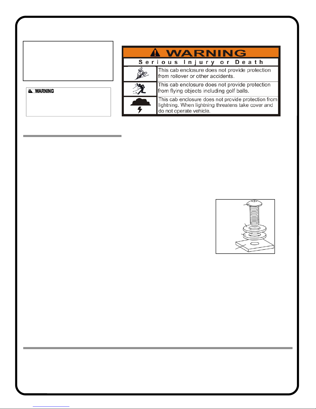
D. Plastic washers have been supplied to provide a
weather seal under the heads of all exterior bolts.
The plastic washer should be installed under each
bolt head directly against the outside cab surface.
Care should be taken not to over tighten the fast eners and damage the plastic washer. Also use
steel washers as required. See diagram.
E. Apply a clear silicone sealant to seal any minor
gaps that may occur due to vehicle variations.
F. Use caution to avoid damaging the factory installed
threaded inserts. Begin the bolt engagement by hand
to guard against potential cross threading.
TOOLS REQUIRED:
Set of standard and metric sockets
Set of standard and metric open end wrenches
Scissors
One Phillips Head and one Flat Screwdriver
One 3/8” Drive Ratchet
One 3/16” Allen Wrench (preferably “T” handle type)
One 5mm Allen Wrench (preferably “T” handle type)
Pliers
Rev. -, p. 2 of 19
Fastener
Steel Washer
Plastic Washer
Cab Surface
Page 3
1. VEHICLE PREP.
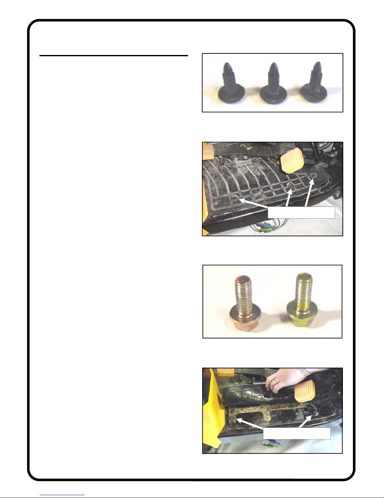
1.1 Per figures 1.1 and 1.1.1, use a flat screwdriver
and pliers to remove three (3) plastic pine tree clips from
the rubber mat on top of the floorboard on each side of
the tractor. Repeat for opposite side. Discard all six. Six
new clips will be installed in step 18.3.
1.2 Per figures 1.2 and 1.2.1, remove two (2) M8 bolts
from underneath the rubber mat per side of the tractor.
Repeat for opposite side. Discard these short bolts. New,
longer M8 button head bolts are supplied in the hardware
bag.
Rev. -, p. 3 of 19
Fig. 1.1 (plastic pine tree clips)
remove 3 clips from here
Fig. 1.1.1 (view from right side)
Fig. 1.2 (two M8 bolts)
remove 2 bolts from here
Fig. 1.2.1 (view from right side)
Page 4
1. VEHICLE PREP. (cont’d.)
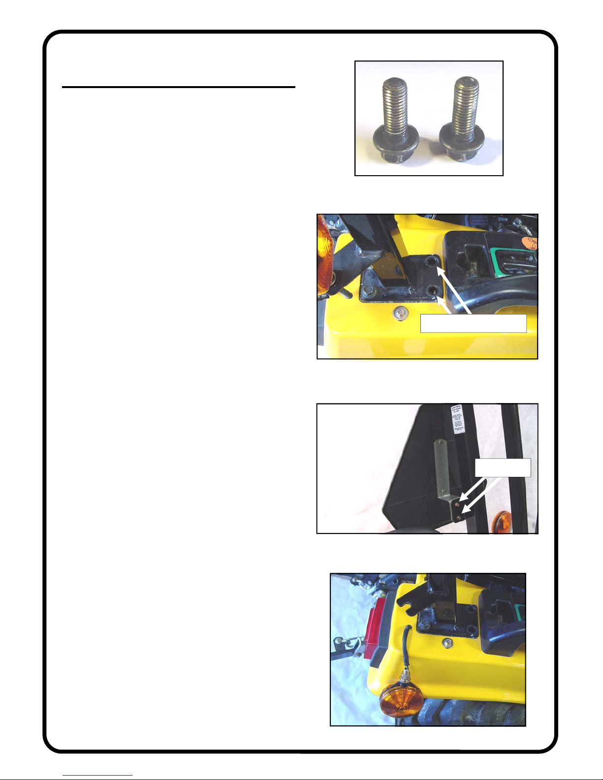
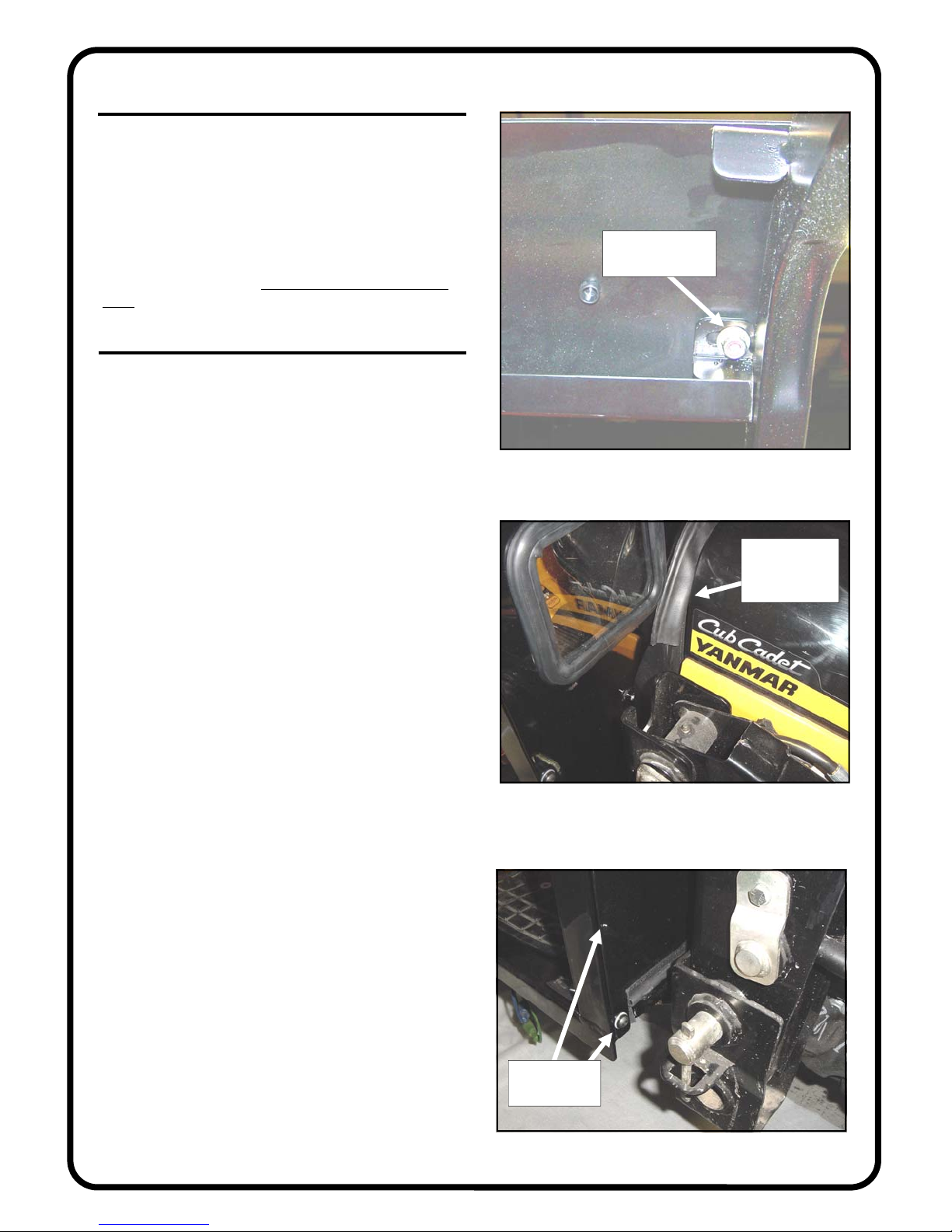
1.3 Per figures 1.3 and 1.3.1, remove two (2) M12
bolts from the bottom front area of the ROPS structure as
shown. Repeat for opposite side of tractor. Discard all
four bolts. New, longer hardware is supplied.
1.4 Per fig. 1.4, remove two (2) bolts from behind the
SMV sign (slow moving vehicle sign). Save these two
bolts for re-installation in step 18.6.
1.5 Per fig. 1.5, loosen the large hex nut on the rear
flasher lights, slide the assembly out the open ended slot
in the bracket, and temporarily rest the flasher assembly
against the side of the fender as shown. Repeat for opposite side.
Rev. -, p. 4 of 19
Fig. 1.3 (two M12 bolts)
remove 2 bolts from here
Fig. 1.3.1 (view from right side)
these 2 bolts
Fig. 1.4 (view from inside cab)
Fig. 1.5 (view from right side)
Page 5
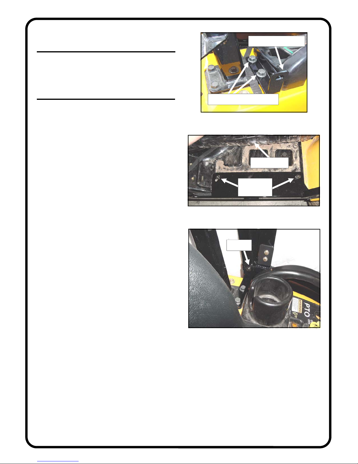
2. REAR MOUNT BRACKET
2.1 Per fig. 2.1, install the right side rear mount
bracket as shown with the notch pointing forward. Use
the two new, longer M12 bolts supplied. Leave bolts
loose. Repeat for opposite side..
Rev. -, p. 5 of 19
notch to point forward
3. SIDE FRAMES
3.1 For ease of handling, remove the door from the
side frame by lifting up and off the pin hinges that are
bolted to the side frame.
3.2 See fig. 3.2. With assistance, install the right side
frame to the tractor. The floorboard of the side frame is
to be underneath the rubber mat. Use a 5mm Allen
wrench and the following hardware per side: two M8
button head bolts and two steel washers. Note: these
thread into the original equipment weldnuts under the
tractor floorboard. Use caution to avoid cross threading
the weldnuts. Begin the thread engagement by hand.
Leave bolts loose. Repeat for opposite side.
3.3 Per fig. 3.3, install the following hardware through
the rear mount bracket and into factory installed threaded
inserts in the lower rear corners of the side frames: one
5/16-18 x 3/4” long button head bolt and one steel
washer. Leave bolt loose. Repeat for opposite side.
install two new, longer bolts
Fig. 2.1 (view from right side)
lift rubber mat
2 bolts and
washers here
Fig. 3.2 (view from right side)
bolt here
Fig. 3.3 (view from inside the cab)
Page 6
4. WINDSHIELD SUPPORT
4.1 Per fig. 4.1, install the windshield support to the
top front corner of the side frames. Orient the windshield
support so the bent flanges are down and the decals are
legible. Use the following hardware in the lower hole on
each side (note: the remaining holes will receive hardware when the roof is installed): one 5/16- 1 8 x 3/ 4” l on g
button head bolt, one plastic washer, two steel washers,
and one locknut. Locknuts to be on the inside of the cab.
Repeat for opposite side. Tighten these two bolts at this
time.
5. COWL
5.1 Per fig. 5.1, install the cowl with the bent flanges up
top and towards the inside of the cab. The arched piece
of bulb rubber sits in the gap between the hood and the
console as shown.
5.2 Per fig. 5.2, use the following hardware per side:
three 5/16-18 x 3/4” long button head bolts, three plastic
washers, and three steel washers. Leave loose. Repeat for
opposite side.
Rev. -, p. 6 of 19
steel washer and
locknut inside
Fig. 4.1 (view from right rear side of tractor)
bulb rubber to
be in this gap
as shown
Fig. 5.1 (view from right front side of tracto r )
use plastic
washers here
Fig. 5.2 (view from right front side of tracto r )
Page 7

6. ROLL BAR BRACKET
6.1 If installing an optional hard rear panel at this
time, skip to step 7 on the next page. (Note: the steel rear
mount shown in fig. 6.2 is not used with the optional
hard rear panel).
6.2 Per fig. 6.2, install the supplied rubber vibration
mount to the rear mount using the following hardware:
1/4-20 x 1” long button head bolt, one steel washer, and
one locknut. The head of the bolt is to be inside the recess in the rubber. The washer is to be used on the locknut side. Repeat for the other rear mount. Tighten these
bolts.
6.3 Per fig. 6.3, attach the rear mount to the back of
the side frame using the following hardware per side: two
5/16-18 x 3/4” long button head bolt and two steel wash ers into factory installed threaded inserts in the rear middle of the side frames. The rubber vibration mount is to
be up against the front face of the ROPS tubing. Leave
bolts loose. Repeat for the opposite side.
6.4 Per fig. 6.4, assemble the roll bar bracket to the
rear mount as shown. Use the following hardware: two
5/16-18 x 1” long button head bolts, 4 steel washers, and
two locknuts. The head of the bolts are to be towards the
rear of the tractor. Leave bolts loose. Repeat for opposite
side.
Rev. -, p. 7 of 19
Fig. 6.2 (rear mount)
Fig. 6.3 (view from left rear side)
head of bolt
Fig. 6.4 (view from rear right side)
Page 8

7. OPTIONAL REAR LEGS
7.1 Per fig. 7.1, install the supplied rubber vibration
mount to the rear leg using the following hardware: 1/420 x 1” long button head bolt, one steel washer, and one
locknut. The head of the bolt is to be inside the recess in
the rubber. The washer is to be used on the locknut side.
The vibration mount is to be on the same side as the bent
flange as shown. Repeat for the other rear leg. Tighten
these bolts.
7.2 Per fig. 7.2, install the right side rear leg (see fig–
ure 7.1) to the back of the side frame oriented so the rubber vibration mount is up against the front face of the
ROPS tubing and the long bent flange is inboard and
pointing towards the rear. Use the following hardware
per side: six 5/16-18 x 3/4” long button head bolts, six
plastic washers, and six steel washers. These thread into
factory installed threaded inserts. Leave bolts loose. Repeat for opposite side.
7.3 Per fig. 7.2, attach the roll bar bracket to the rear
leg using the following hardware per side: two 5/16-18 x
1” long button head bolts, two plastic washers, four steel
washers, and two locknuts. The heads of the bolts to be
outboard towards the rear of the tractor. Leave bolts
loose. Repeat for opposite side.
8. OPTIONAL HARD REAR PANEL
8.1 Per fig. 8.1, attach the hard rear panel to the rear
legs oriented so the large window is down and the upper
bent flange is pointing towards the front of the tractor.
Position the hard rear panel so the left and right bent
flanges are outboard
following hardware per side: three 5/16-18 x 3/4” long
button head bolts, 6 steel washers, 3 plastic washers, and
3 locknuts. Locknuts to be on the inside surface. Repeat
for opposite side. Leave bolts loose.
of the rear leg bent flanges. Use the
Rev. -, p. 8 of 19
bent flanges
are shown
up in this view
this is the right
side rear leg
Fig. 7.1 (rear legs)
step 7.2
(side frame bolts)
step 7.3
(roll bar bracket bolts)
head of bolt, plastic
and steel washers
Fig. 8.1 (view from right rear side of tractor)
Fig. 7.2 (view from right rear side)
Page 9

9. WINDSHIELD
9.1 See fig. 9.1. Have the following items ready: four
5/16-18 x 1 3/4” long flat head bolts, 4 steel washers, 4
locknuts, and 2 plastic spacer blocks. With assistance,
install the windshield hinges to the windshield support
with the two spacer blocks between the hinge and the
windshield support. Attach windshield latches to windshield latch receivers on the cowl by squeezing tabs to
retract spring loaded pins. See fig. 9.1.1. Lift up on bottom of windshield and close latches. Check alignment of
windshield with side frames and tighten hinge hardware.
CAUTION: hinges are plastic components. Do not
overtighten hardware. Torque to 7 foot-pounds max..
10. ROOF
10.1 If an optional hard rear panel was installed, the six
soft rear curtain snaps pre-assembled onto the back surface of the roof can be left in place or removed and discarded at the installer’s discretion.
10.2 Use a Phillips head screwdriver to punch a hole
through the headliner at all of the covered bolt hole locations (10 places). Punch holes from the inside out to
avoid having the headliner pull away from its glued surface.
10.3 With assistance, install the roof oriented so the
reflectors are towards the rear of the tractor. If installing
an optional hard rear panel, the back of the roof must go
over the tops of the rear legs and rear panel so they are
contained. Per figure 10.3, use the following hardware in
the front corners: one 5/16-18 x 1” long button head bolt,
two steel washers, one plastic washer, and one locknut
(locknuts on the inside surface). Install the bolt through
the roof, windshield support, and mounting tab. Leave
loose.
10.4 The bolt hole locations over the left and right side
frames use the following hardware per side: two 5/16-18
x 3/4” long button head bolts, two steel washers, an d tw o
plastic washers. These bolts are installed into factory
installed threaded inserts in the top of each side frame.
NOTE
: use caution to avoid damaging the internal
threads on the factory installed threaded inserts. Leave
loose.
10.5 The remaining four holes use the following hardware: four 5/16-18 x 3/4” long button head bol t s, 8 steel
washers, 4 plastic washers, and 4 locknuts. Locknuts to
be on the inside surface. Note: the two middle rear bolts
are used for both hard or soft rear panels. When installing
the standard soft rear panel, the two middle rear bolts
serve only as weather plugs in the existing roof holes.
Rev. -, p. 9 of 19
sandwich the
plastic spacer
block here
Fig. 9.1 (view from left front side of tractor )
latch receiver
Fig. 9.1.1 (view from right rear side of tractor)
1” long bolt here
1” long bolt here
Fig. 10.3 (view from right front side of tractor)
Page 10

11. TIGHTEN ALL BOLTS
11.1 Before and during bolt tightening, measure and
offset the side frames symmetrical to the ROPS tubing on
the rear of the tractor. Shift and/or push cab as necessary
before tightening all bolts. Tighten all bolts including
those under the floor mats, etc.. NOTE: torque the large
M12 bolts on the lower front of the ROPS tubing back to
the original equipment specifications to ensure full safety
standards.
12. AIR INTAKE SHIELD
12.1 Install the shield using two supplied hand knobs
per side (see figures 12.1). Note: hand knobs are used so
the shield is easily removable for operator access to the
battery and the front of the radiator for clean-outs.
12.2 Per figures 12.2 and 12.2.1, orient and install the
shield so the half circle relief is up top as shown.
Rev. -, p. 10 of 19
Fig. 12.1 (hand knobs)
relief up top
Fig. 12.2 (view from rear of tractor)
hand knobs
Fig. 12.2.1 (view from right front side of tractor)
Page 11

13. VINYL FILLERS (qty.: 4)
13.1 Per fig. 13.1, raise the seat and install the smaller
of the two rectangular vinyl fillers as shown. Note: the
slightly larger rectangular filler is for the air intake
shield.
13.2 Fig. 13.2 shows the filler temporarily peeled back
to show the application of the narrow 5/8” wide PSA
(pressure sensitive adhesive) hook velcro. Only three (3)
edges of the rectangle will receive mating velcro. As
shown, do not install the velcro underneath the forward
most edge of the filler so the decal will not be obstructed
and this will allow easier grasping and opening of the
filler for servicing. Note: make sure the surfaces of the
tractor are clean, dry, and at room temperature for best
adhesion of the velcro.
13.3 Per figures 13.3 through 13.3.4, install the larger
underseat filler. Photos continued on the next page. Dry
fit the filler in place to determine where all the flaps fit
best then install the narrow 5/8” wide PSA hook velcro
onto the mating velcro on the filler. Peel back the protective strip and adhere on to the tractor to suit. Reminder:
make sure the surfaces of the tractor are clean, dry, and at
room temperature for best adhesion of the velcro.
Rev. -, p. 11 of 19
seat shown tilted up 90 degrees
rectangular filler
Fig. 13.1 (view from left side of tractor)
do not
apply
hook
PSA
velcro
here
large underseat filler
Fig. 13.3.1 (view from right side of tractor w/ seat up)
Fig. 13.2 (view from left side of tractor)
Fig. 13.3 (underseat vinyl fillers)
Page 12

13. VINYL FILLERS (cont’d.)
13.4 Install the filler to suit. Note: the narrow front portion pointed out in fig. 13.3.2 has mating velcro strips for
connection onto each other for closure. Note: the rear
portion of this filler will either connect to the bottom of a
soft rear curtain or an optional hard rear panel as the installation continues.
13.5 Per fig. 13.5 and the photos on the next page, install this vinyl filler shown to the very bottom of the air
intake shield.
Rev. -, p. 12 of 19
velcro the
left onto
the right
large underseat filler
Fig. 13.3.2 (view from left side of tractor)
large underseat filler
Fig. 13.3.3 (view from left side of tractor)
large underseat filler
Fig. 13.3.4 (view from right side of tractor)
Fig. 13.5 (lower filler for air intake shield)
Page 13

13. VINYL FILLERS (cont’d.)
13.6 Orient the filler so the pocket for the fuel fill cap
is on the left side where required. Per figures 13.6
through 13.6.3, apply narrow 5/8” wide PSA hook velcro
to the very bottom horizontal edge of the air intake
shield. Apply narrow 5/8” wide PSA hook velcro on the
plastic tractor cowl (above the decals
remainder of the filler to suit.
). Fit and install the
Rev. -, p. 13 of 19
position the
velcro above
the decal
ref.: pocket for
fuel fill cap
Fig. 13.6 (view from left side of tractor)
fuel cap is under here
position the
velcro above
the decal
Fig. 13.6.1 (view from right side of tractor)
the filler velcros onto itself here
Fig. 13.6.3 (view from left side of tractor)
Fig. 13.6.2 (view from right side of tractor)
Page 14

13. VINYL FILLERS (cont’d.)
13.7 Per fig. 13.7, apply narrow 5/8” wide PSA hook
velcro along four sides of the rectangular air flow openings as shown.
13.8 Per fig. 13.8, install the final rectangular filler
over the air flow openings onto the newly installed velcro. Note: the air shield filler is the larger of the two rectangular pieces provided. This filler is used in cooler
weather to help keep heat in the cab. In warmer weather,
the filler can be removed for increased air flow to the
radiator.
14. SOFT REAR CURTAIN
14.1 If not installing a soft rear curtain, skip to step 15
on the next page.
14.2 Snap the rear curtain to the factory installed snaps
on the inside surface of the back of the roof (6 snaps).
14.3 Per fig. 14.3, apply large 1” wide PSA (pressure
sensitive adhesive) hook velcro to the back inside surface
of the vertical rear tube of the side frames. Continue the
hook velcro 90 degrees on to the yellow fender of the
tractor. Note: surfaces must be clean, dry, and at room
temperature for best adhesion.
14.4 Attach the loose rear edge of the underseat filler to
the bottom of the soft rear curtain and work the velcroed
flaps around the seatbelts to suit. See fig. 14.4.
Rev. -, p. 14 of 19
velcro all around perimeter
of rectangular vent opening
Fig. 13.7 (air shield vinyl filler)
filler installed
Fig. 13.8 (air shield vinyl filler)
soft rear
curtain
filler velcros
onto itself
around seatbelts
Fig. 14.4 (view from right side of tractor)
Fig. 14.3 (view from left rear side of tractor)
5/8” wide
velcro
1” wide
velcro
Fig. 14.3 (view from left rear side of tractor)
Page 15

15. DOORS
15.1 Apply grease to the pin hinges. With assistance, reinstall the doors onto the pin hinges. Work the doors back
and forth until the hinges are completely seated.
Specific adjustments can be made per steps 15.2 and 15.3.
Note: top of door should end up visually parallel with side of
roof. Note: the door latch is a rotary type with two positions
to close. Adjust door so that when fully closed door latch
clicks twice
15.2 Per fig. 15.2, the large striker bolt and nut can be loosened and reset higher or lower or forward or back for better
engagement in the door latch assembly if necessary. Use two
3/4” open end wrenches. Note: finger guard to end up being
centered and facing inward.
15.3 Per fig. 15.3, the 1/4-20 hex head bolts on the door
hinges can be loosened on the rear tube, or on the door itself,
or in both places, in order to slightly rotate the door up or
down as necessary for proper latch assembly and striker bolt
engagement. Note: an assistant will be needed for this step.
Keep the hinge sleeves fully seated on the pin hinges.
Tighten all hinge bolts using caution to not
Over tightening will crush (damage) the structural tubing.
Torque to 40 inch/pounds.
CAUTION:
WITH DOORS OPEN. MAKE SURE DOORS ARE
CLOSED AND PROPERLY LATCHED WHEN DRIVING.
for total engagement.
over tighten.
FOR SAFE OPERATION, DO NOT DRIVE
16. LUBRICATION
16.1 Once the doors are properly adjusted, lubrication
(preferably grease) can be applied to the striker bolts and
door latch assemblies. Re-apply periodically as needed (same
goes for the door pin hinges as necessary).
Rev. -, p. 15 of 19
Fig. 15.2 (striker bolt)
EXTERIOR
VIEW OF
RIGHT SIDE
DOOR
Fig. 15.3 (right side door)
Page 16

17. FLASHER LIGHT BRACKET
17.1 Per fig. 17.1, install the flasher light brackets using
the following hardware per side of the tractor: one 5/16-18 x
3/4” long button head bolt, two steel washers, and one locknut. Repeat for the opposite side. Tighten the bolts.
17.2 Per fig. 17.2, re-install the flasher light. Note: both
washers (flat and lock) to be on the bottom side of the
bracket along with the hex nut.
18. FINISHING TOUCHES
18.1 Install the gas shock to the frame and door with the
small piston end towards the door. Press the button on the
compression fastener to lock the gas shock to the ball stud.
18.2 Install the supplied 5/16” nut covers (qty.: 16) on the
interior hex locknuts by snapping over nut. Install the two
1/4” nut covers on the locknuts for the vibration mounts.
18.3 Install six (6) new plastic pine tree clips (3 per side)
through the rubber floor mats. Press in place by hand.
Rev. -, p. 16 of 19
open
ended
slot to be
outboard
Fig. 17.1 (view from right side of tractor)
Fig. 17.2 (view from right side of tractor)
install 3 pine tree
clips per side
Fig. 18.3 (view from right side of tractor)
Page 17

18. FINISHING TOUCHES (cont’d.)
18.4 If a soft rear curtain has been installed, install the following hardware into the factory installed threaded inserts in
the back of each of the side frames: four 5/16-18 x 3/4” long
button head bolts, four plastic washers, and four steel washers. See fig. 18.4. These will serve as weather plugs when an
optional hard rear panel is not installed.
18.5 If an optional hard rear panel has been installed, apply
PSA hook velcro to the lower inside surface and attach the
loose rear edge of the underseat filler. Work the velcroed
flaps around the seatbelts to suit. See fig. 18.5.
18.6 Re-install the SMV sign using the original equipment
hardware. See fig. 18.6.
18.7 Peel protective film from windows.
18.8 Note: extra hardware has been provided in case they
get lost. Discard extras such as washers, e t c.
18.9 Install the front windshield wiper per the installation
instructions included with the wiper kit.
18.10 Additional optional equipment available: Work
Lights, Heater, Hard Rear Panel, Sliding Door Windows, and
Rear Window
19. CARE AND MAINTENANCE
19.1 Check and tighten hardware after 40 hours of operation. Periodically inspect and tighten hardware for the remainder of the unit’s life.
19.2 Wash the painted surfaces of the unit with commercial automotive cleaning products.
19.3 Clean windows with glass cleaner.
19.4 Vinyl components should be washed with a mild solution of warm soapy water.
19.5 Clear vinyl can be easily scratched. Be careful cleaning frost or snow from rear curtain. Do not roll curtain in
cold weather. The curtain becomes stiff and may crack. Keep
curtain clean.
Rev. -, p. 17 of 19
fill threaded inserts
Fig. 18.4 (view from right rear side of tractor)
filler velcros
onto itself
around seatbelts
Fig. 18.5 (view from right side of tractor)
these 2 bolts
Fig. 18.6 (view from inside the cab)
Page 18

Page 19

 Loading...