

Page 1

Page 2

Page 3

INTRODUCTION
Welcome to the World of Cub Cadet Yanmar Tractor
Thank you for purchasing our tractor product that has been designed and
manufactured based on our state-of-the-art technology and rich expertise in
developing and manufacturing tractor products.
Handle your tractor correctly by following the instructions contained in this
Operator’s Manual so that it provides you long years of reliable and faithful
service.
This manual constitutes an indispensable part of your Cub Cadet Yanmar tractor
product. Always keep the manual readily accessible.
Carefully study this manual to get familiar with the instructions and information
contained in it. These instructions and information are helpful in using your
tractor correctly and safely, and avoiding personal injury and other accidents
during operation and servicing of the tractor.
When using any implement together with your tractor, also carefully study its
operation manual so that you can use it safely, correctly and efficiently.
This manual is organized with sections arranged in a particular order so that you
can better understand the safety messages and the controls on your tractor to
help you operate your tractor correctly and safely. This manual will also help you
answer questions about operation and servicing. An index is available at the end
of this manual to assist you in quickly finding necessary information.
The machine shown in this manual may somewhat differ from your actual
machine. However, this manual will still assist you in understanding the
instructions associated with your tractor.
Before delivery of your machine, your Cub Cadet Yanmar dealer has performed
a pre-delivery check to ensure that your tractor can long remain problem-free.
All information, descriptions, specifications, drawings, illustrations, and pictures
in this manual are based on the latest information available at the time this
manual was published. Yanmar reserves the right to make changes at any time
without prior notice.
© 2008 - 2010 Yanmar Co., Ltd.
Yanmar licenses the usage rights of this manual in North America to CUTSCO
(Compact Utility Tractor Supply LLC).
© 2008 - 2010
1
Sc2400 Operator’s Manual
Page 4

PICTOGRAPHS
To help assist the operator in operating the tractor, various easy-to-understand pictographs have been
developed and are used throughout this manual. They are listed below together with their meanings.
<Lights>
Safety alert symbol
Headlight beam
<Instrument panel>
Turn signal
Fuel level
Revolutions per minute
Engine coolant warning light
Preheater pilot light
Engine oil pressure
Alternator/battery charging light
<Starter key switch>
Engine start
Headlight and work light
Hazard warning light
<Levers and knobs>
Slow
Fast
Hydro Static Transmission
(HST) pressure locked
position
Hydro Static Transmission
(HST) pressure released
position
Position for moving only the Mid-Power
Take Off (PTO)
Position for moving the Mid- and Rear
Power Take Off (PTO) at the same time
Engine run
Engine shut-off
Preheating
<Lights>
Turn signal
Headlight
Sc2400 Operator's Manual
Position for moving only the Rear
Power Take Off (PTO)
Position control raised position
Position control lowered position
Hydraulic flow control/stop
4-wheel drive on
2-wheel drive on
2
Page 5

TABLE OF CONTENTS
1. SAFETY PRECAUTIONS ................................................................................... 1-1
1. About This Manual .................................................................................................................. 1-1
2. Safety-Alert Symbols............................................................................................................... 1-2
3. Precautions before Operating Your Tractor ............................................................................ 1-3
4. Safe Practices for Operating Your Tractor .............................................................................. 1-4
5. Operate Your Tractor on Slopes ............................................................................................. 1-6
6. Travel on a Road..................................................................................................................... 1-7
7. Safe Practices for Parking Your Tractor.................................................................................. 1-7
8. Operate the Power Take Off (PTO)......................................................................................... 1-8
9. Use the 3-Point Hitch .............................................................................................................. 1-8
10.Safety Frame (Roll-Over Protective Structure) (ROPS) Precautions ...................................... 1-8
11.Safe Practices for Servicing Your Tractor ............................................................................... 1-9
12.Understand the Tractor Safety Decals .................................................................................. 1-11
Safety-Alert Symbols ...........................................................................................................................................1-11
Care of DANGER, WARNING and CAUTION Decals.........................................................................................1-11
2. SERVICE THE TRACTOR .................................................................................. 2-1
3. SPECIFICATIONS............................................................................................... 3-1
1. Specifications Table ................................................................................................................ 3-1
2. Traveling Speeds (Reference) ................................................................................................ 3-2
4. IMPLEMENT CAPACITIES................................................................................. 4-1
5. NAMES AND FUNCTIONS OF COMPONENTS ................................................ 5-1
1. Overview ................................................................................................................................. 5-1
2. Operator Station Controls........................................................................................................ 5-2
Function of Components .......................................................................................................................................5-3
3. Instrument Panel, Switches and Hand Controls.................................................................... 5-11
6. PRE-OPERATION CHECK ................................................................................. 6-1
1. Pre-Operation Check............................................................................................................... 6-1
2. Precautions before the Operation ........................................................................................... 6-1
3. Routine Check......................................................................................................................... 6-1
4. Prevent Damage to the Plastic Surfaces and Painted Surfaces ............................................. 6-1
3
Sc2400 Operator’s Manual
Page 6

TABLE OF CONTENTS
7. OPERATE THE ENGINE .................................................................................... 7-1
1. Start the Engine....................................................................................................................... 7-2
Opening/Closing the Fuel Shut-Off Valve..............................................................................................................7-2
Adjust the Operator's Seat.....................................................................................................................................7-2
Fasten the Retractable Seat Belt...........................................................................................................................7-2
Engage the Parking Brake.....................................................................................................................................7-3
Check the Lights on the Instrument Panel.............................................................................................................7-6
Warm Up the Engine in Cold Weather ..................................................................................................................7-7
2. Shut Down the Engine............................................................................................................. 7-8
3. Restart a Stalled Engine.......................................................................................................... 7-9
8. OPERATE THE TRACTOR................................................................................. 8-1
1. Operate a New Tractor............................................................................................................ 8-2
2. Operate the Tractor................................................................................................................. 8-3
Function of Implement Lock Lever ........................................................................................................................8-5
Engage the Cruise Control ....................................................................................................................................8-7
Disengage the Cruise Control ...............................................................................................................................8-7
3. Stop the Tractor....................................................................................................................... 8-8
Stop in an Emergency ...........................................................................................................................................8-8
4. Verify During Driving ............................................................................................................... 8-9
Fuel Gauge..........................................................................................................................................................8-10
Engine Coolant Warning Light .............................................................................................................................8-10
Hour Meter...........................................................................................................................................................8-11
5. Park the Tractor..................................................................................................................... 8-12
Apply the Parking Brake ......................................................................................................................................8-12
Release the Parking Brake ..................................................................................................................................8-12
6. Safe Practices for Operation ................................................................................................. 8-13
Engage the Differential Lock ...............................................................................................................................8-13
Disengage the Differential Lock...........................................................................................................................8-13
Hydro Static Transmission (HST) Pressure Release Lever.................................................................................8-16
Uphill/Downhill .....................................................................................................................................................8-19
Steep Downhill.....................................................................................................................................................8-19
7. Accessory.............................................................................................................................. 8-20
12V DC Outlet .....................................................................................................................................................8-20
9. POWER TAKE OFF (PTO) ................................................................................. 9-1
1. Operate the Power Take Off (PTO)......................................................................................... 9-1
Rear Power Take Off (PTO) ..................................................................................................................................9-2
Mid-Power Take Off (PTO)....................................................................................................................................9-2
Engage the Power Take Off (PTO) .......................................................................................................................9-2
Disengage the Power Take Off (PTO)...................................................................................................................9-4
2. Install an Implement to the Power Take Off (PTO) Drivelines................................................. 9-5
3. Operate the Power Take Off (PTO) while the Tractor is Traveling
in the Reverse Direction (Reverse Override Function)............................................................ 9-5
10.3-POINT HITCH ................................................................................................ 10-1
1. 3-Point Hitch.......................................................................................................................... 10-1
Right Lift Link.......................................................................................................................................................10-2
Top Link...............................................................................................................................................................10-2
Sway Link ............................................................................................................................................................10-2
Hitch ....................................................................................................................................................................10-2
Sc2400 Operator’s Manual
4
Page 7

TABLE OF CONTENTS
11.HYDRAULIC SYSTEM...................................................................................... 11-1
1. 3-Point Hitch Control System ................................................................................................ 11-1
Operate the 3-Point Hitch Control/Cutting Height Adjustment Lever to Raise or Lower the 3-Point Hitch..........11-1
Hydraulic Flow Control/Stop Knob.......................................................................................................................11-2
2. Control the Implement Control Valve (Option) ...................................................................... 11-3
Implement Control Valve (Option) .......................................................................................................................11-3
Implement Control Lever (Option) .......................................................................................................................11-4
Implement Lock Lever (Option) ...........................................................................................................................11-4
Connect the Implement Hydraulic Hoses ............................................................................................................11-5
12.TIRES, WHEELS AND BALLAST .................................................................... 12-1
1. Tires ...................................................................................................................................... 12-1
Tire Inflation Pressure .........................................................................................................................................12-2
Wheel Bolt Tightening Torque .............................................................................................................................12-2
2. Ballast.................................................................................................................................... 12-3
Front Ballast ........................................................................................................................................................12-3
Rear Ballast .........................................................................................................................................................12-4
13.MAINTENANCE ................................................................................................ 13-1
1. Maintenance Check List ........................................................................................................ 13-1
2. Lubricants.............................................................................................................................. 13-2
3. Replacement Parts................................................................................................................ 13-3
14.PERIODIC SERVICE ........................................................................................ 14-1
■ Warranty and Repair of the Engine....................................................................................... 14-1
1. Open/Close the Hood............................................................................................................ 14-2
Open the Hood ....................................................................................................................................................14-2
Close the Hood ....................................................................................................................................................14-2
2. Daily Checks ......................................................................................................................... 14-3
Visual Checks ......................................................................................................................................................14-3
Refill the Fuel Tank..............................................................................................................................................14-3
Check the Engine Oil Level .................................................................................................................................14-7
Check the Transmission/Hydraulic Oil Level .......................................................................................................14-8
Check the Radiator Hoses and Clamps ..............................................................................................................14-9
Clean the Radiator Cooling Fins and Screen ......................................................................................................14-9
Clean the Rear Grille Screen.............................................................................................................................14-10
Check the Cooling System ................................................................................................................................14-11
Check the Fuel Line...........................................................................................................................................14-12
Check the Intake Air Hoses and Clamps...........................................................................................................14-12
Check the Safety Interlock System....................................................................................................................14-13
Check and Adjust the Brake ..............................................................................................................................14-15
Check the Seat Belt and Roll-Over Protective Structure (ROPS)......................................................................14-15
Check the Wheel Bolt Tightening Torque ..........................................................................................................14-16
Check the Inflation Pressure .............................................................................................................................14-16
Check the Light Bulbs........................................................................................................................................14-17
Check the Tie-rod Rubber Boots .......................................................................................................................14-17
Check and Clean the Electrical System ............................................................................................................14-17
Adjust Front Axle Pivot ......................................................................................................................................14-18
Check the Hydraulic Hoses ...............................................................................................................................14-19
5
Sc2400 Operator’s Manual
Page 8

TABLE OF CONTENTS
3. First 50 Hours...................................................................................................................... 14-21
Change the Engine Oil ......................................................................................................................................14-21
Replace the Engine Oil Filter.............................................................................................................................14-21
Change the Transmission/Hydraulic Oil ............................................................................................................14-21
Replace the Transmission/Hydraulic Oil Filter...................................................................................................14-21
4. Every 50 Hours.................................................................................................................... 14-21
Check the Front Axle Oil Level ..........................................................................................................................14-21
Check the Fuel/Water Separator .......................................................................................................................14-22
Adjust the Fan Belt ............................................................................................................................................14-23
Grease and Lubricate ........................................................................................................................................14-24
5. Every 100 Hours.................................................................................................................. 14-26
Engine Oil ..........................................................................................................................................................14-26
Change the Engine Oil ......................................................................................................................................14-26
Clean the Fuel/Water Separator........................................................................................................................14-27
Service the Air Cleaner Element .......................................................................................................................14-28
6. Every 200 Hours.................................................................................................................. 14-30
Replace the Engine Oil Filter.............................................................................................................................14-30
Adjust the Toe-in ...............................................................................................................................................14-31
7. Every 300 Hours.................................................................................................................. 14-32
Transmission/Hydraulic Oil................................................................................................................................14-32
Change the Transmission/Hydraulic Oil and Replace the Transmission/Hydraulic Oil Filter ............................14-32
8. Every 500 Hours.................................................................................................................. 14-34
Front Axle Case Oil ...........................................................................................................................................14-34
Change the Front Axle Case Oil........................................................................................................................14-34
Replace the Fuel Filter Element (in the Fuel/Water Separator).........................................................................14-35
Replace the Fuel Filter ......................................................................................................................................14-35
9. Every 1000 Hours................................................................................................................ 14-36
Coolant ..............................................................................................................................................................14-36
Flush the Cooling System..................................................................................................................................14-37
Change the Coolant...........................................................................................................................................14-39
10.Every 1 Year........................................................................................................................ 14-40
Replace the Air Cleaner Element ......................................................................................................................14-40
Flush the Cooling System..................................................................................................................................14-40
Change the Coolant...........................................................................................................................................14-40
11.Every 2 Years...................................................................................................................... 14-40
Replace the Radiator Hoses and Clamp ...........................................................................................................14-40
Replace the Fuel Line........................................................................................................................................14-40
Replace the Intake Air Hose..............................................................................................................................14-40
Replace the Hydraulic Hoses ............................................................................................................................14-40
Sc2400 Operator’s Manual
6
Page 9

TABLE OF CONTENTS
15.SERVICE THE ELECTRICAL SYSTEM ........................................................... 15-1
1. Battery ................................................................................................................................... 15-1
Special Note for the Battery.................................................................................................................................15-1
Service the Battery Safely ...................................................................................................................................15-2
Inspect the Battery...............................................................................................................................................15-3
Remove and Install the Battery ...........................................................................................................................15-3
Clean the Battery and Terminals .........................................................................................................................15-4
Use a Booster Battery .........................................................................................................................................15-5
2. Fuses..................................................................................................................................... 15-6
Replace the Accessory Fuses .............................................................................................................................15-6
Check the Alternator Fuse and the Main Fuse ....................................................................................................15-6
3. Bulb ....................................................................................................................................... 15-7
Replace the Headlight Bulb .................................................................................................................................15-7
Replace the Work Light Bulb ...............................................................................................................................15-8
Replace the Tail Light Bulb..................................................................................................................................15-9
Replace the Turn Signal/Hazard Lights Bulb.......................................................................................................15-9
Replace the Instrument Panel Light Bulb ..........................................................................................................15-10
4. Headlights ........................................................................................................................... 15-10
Adjust the Headlights.........................................................................................................................................15-10
16.STORE THE TRACTOR ................................................................................... 16-1
1. Safe Practices for Storage .................................................................................................... 16-1
Fuel......................................................................................................................................................................16-2
Engine .................................................................................................................................................................16-2
2. Prepare the Stored Tractor for Operation.............................................................................. 16-3
17.TROUBLESHOOTING ...................................................................................... 17-1
1. Guide in Using the Troubleshooting Table............................................................................ 17-1
18.INDEX................................................................................................................ 18-1
7
Sc2400 Operator’s Manual
Page 10

1. SAFETY PRECAUTIONS
1. SAFETY PRECAUTIONS
1. About This Manual
This Operator’s Manual presents you messages that
help you remain aware of potential hazards and
possible machine damage in operating and servicing
your machine. Carefully study all the information in it
so that you can avoid personal injury and damaged
properties.
NOTE
●Unless otherwise stated, the expressions–righthand side, left-hand side, front side, and rear side,
used throughout this manual see the sides relative
to the direction of forward movement with the
tractor.
P3014903
RIGHT
FRONT
REAR
LEFT
Sc2400 Operator’s Manual
1-1
Page 11

2. Safety-Alert Symbols
1. SAFETY PRECAUTIONS
The safety-alert symbols appear with
most safety statements. It means
attention, become alert, your safety is
involved!
Please read and strictly observe the
message that follows the safety-alert
symbols.
! DANGER
Indicates a hazardous situation which, if not
avoided, will result in death or serious injury.
! WARNING
! WARNING
Indicates a hazardous situation which, if not
avoided, could result in death or serious injury.
WARNING: READ AND FOLLOW ALL INSTRUCTIONS IN THIS MANUAL BEFORE
ATTEMPTING TO OPERATE YOUR TRACTOR. FAILURE TO COMPLY WITH THESE
INSTRUCTIONS MAY RESULT IN PERSONAL INJURY.
WARNING: The engine exhaust, some of its constituents, and certain vehicle components
contain or emit chemicals known to the State of California to cause cancer, birth defects or other
reproductive harm.
! CAUTION
Indicates a hazardous situation which, if not
avoided, could result in minor or moderate injury.
NOTICE
Indicates a situation which can cause damage to the
machine, personal property and/or the environment
or cause the equipment to operate improperly.
IMPORTANT: Means that implement or
property damage could occur if instructions are
ignored.
NOTE: Provides useful information.
DANGER: Your tractor was built to be operated according to the rules for safe operation in this
manual. As with any type of power equipment, carelessness or error on the part of the operator can
result in serious injury. To help prevent accidents, read and take the following precautions before
operating this tractor. Failure to observe the following safety instructions could result in serious
injury or death.
1-2
Sc2400 Operator’s Manual
Page 12

1. SAFETY PRECAUTIONS
3. Precautions before Operating Your Tractor
1. Understand the performance and limitations of
your tractor. Carefully study this Operator’s
Manual and learn the instructions in it before
operating or servicing your tractor. Keep the
Operator’s Manual in an easily accessible place.
2. Strictly follow the statements given in the
DANGER, CAUTION and WARNING safety
decals attached to the tractor.
3. For operator safety, always install the Roll-Over
Protective Structure (ROPS).
Keep the seat belt fastened while operating the
tractor with the Roll-Over Protective Structure
(ROPS). This practice will reduce the possibility
of injury or death in the event of roll-over
accident.
If the Roll-Over Protective Structure (ROPS) has
been removed for any reason, be sure to reinstall
all the associated parts before operating the
tractor.
Do not alter the Roll-Over Protective Structure
(ROPS). The altered Roll-Over Protective
Structure (ROPS) may fail to provide the
designed protection.
Replace the damaged Roll-Over Protective
Structure (ROPS) immediately. Contact your
local Cub Cadet Yanmar dealer for technical
assistance.
NEVER alter or repair the Roll-Over Protective
Structure (ROPS). Welding, bending, drilling,
grinding, or cutting may weaken the Roll-Over
Protective Structure (ROPS). Contact your local
Cub Cadet Yanmar dealer for technical
assistance.
4. Always fasten the seat belt while operating the
tractor with the Roll-Over Protective Structure
(ROPS).
Check the seat belt for any damage. Replace the
damaged seat belt immediately. Contact your
local Cub Cadet Yanmar dealer for technical
assistance.
Do not use the seat belt if the tractor does not
have the Roll-Over Protective Structure (ROPS).
5. Check overhead clearance carefully before
driving under power lines, wires, bridges or low
hanging tree branches, before entering or leaving
building, or in any other situation where the
operator and/or Roll-Over Protective Structure
(ROPS) may be struck, which could result in
serious injury.
6. Make sure that any person who will operate the
tractor studies this Operator’s Manual before
operation. Know the controls and how to stop the
machine quickly.
7. Make sure that any person or obstacle is not
under or around the tractor before and during
operation. Be sure to maintain sufficient
overhead clearance above the tractor.
8. Do not operate your tractor and/or implement
installed to it while you are under the influence of
alcohol, drug, medicine or controlled
substance(s) or when you are not fit for operation
of your tractor.
9. For operation, wear close-fitting clothing. When
operating the tractor or working around the
tractor, do not wear loose-fitting clothes or
jewelry, or baggy or damaged clothing. When
caught by a moving part of the tractor, an
accident can result. Cut-off pants or shorts do not
provide protection against flying debris. Never
operate the tractor in bare feet, sandals, or
sneakers. Wear additional protections including
non-slip safety boots or shoes, and safety
goggles and gloves, etc. as appropriate or
required by currently applicable local laws and
regulations. Wear ear protection in a noisy
environment to prevent hearing damage and
reduce operator fatigue.
10. NEVER allow a passenger on any portion of the
tractor.
11. Remain seated in the operator’s station when
operating the tractor.
12. Make sure that the brakes, clutch and other
mechanical components are free from
misadjustment and excessive wear. Replace any
excessively worn or damaged component
immediately. At regular intervals, check that all
the nuts, bolts and screws are appropriately
tightened. (For details, see “Chapter 13.
MAINTENANCE”)
Sc2400 Operator’s Manual
1-3
Page 13

1. SAFETY PRECAUTIONS
13. Always keep your tractor clean. Dust, grease or
grass clippings accumulated on your tractor can
lead to fire accidents or personal injury.
14. Use the handholds and running board steps
when getting on and off the tractor to help prevent
accidental falls. Keep the running boards clear of
mud and debris.
15. Only use the implements that satisfy the
requirements in this manual or are approved by
your Cub Cadet Yanmar dealer. (See “4.
IMPLEMENT CAPACITIES”)
16. When using front or rear mounted implements,
install an appropriate weight(s) to the front or rear
of your tractor to prevent upsetting of the tractor.
If you choose to use the front loader, mount an
implement or ballast to the 3-point hitch in order
to get the tractor to stabilize. Observe the
instructions about safety in the manual for the
implement to be used.
17. Do not attempt to modify your tractor.
Modification can deteriorate the performance
and/or safety of your tractor, possibly leading to
personal injury or property damage.
4. Safe Practices for Operating Your Tractor
1. Starting Your Tractor
1. Remain seated in the operator’s station when
starting the engine, or actuating the levers or
controls. Do not start the engine or operate
controls while standing beside the tractor.
2. Before starting the engine, make sure that the
forward and reverse drive pedal are in the neutral
positions, the parking brake is engaged, and the
Power Take Off (PTO) is disengaged.
3. Always keep the seat belt fastened around your
waist whenever the tractor has the Roll-Over
Protective Structure (ROPS).
4. Start the engine of your tractor only by using the
starter key switch. Do not attempt to start the
engine by short-circuiting across the starter
solenoid terminals with a jumper wire, or by
bypassing the safety start switch. This defeats
the safety interlock circuit and the tractor may
begin to move and/or the Power Take Off (PTO)
shafts may begin to rotate, possibly leading to
personal injury or property damage.
5. Do not run or idle the engine in a confined area
that is poorly ventilated or not ventilated at all.
The engine emits carbon monoxide gas that is
colorless, odorless and can cause death.
6. Before operation, check that all the safety
features are functioning correctly. Never tamper
with safety devices. Check their proper operation
regularly. Contact your Cub Cadet Yanmar dealer
if safety devices malfunction.
7. Avoid accidental contact with control pedals while
the engine is running, as this can cause
unexpected movement of the tractor.
8. Never leave a running machine unattended.
9. Do not attach or use towed equipment by a
drawbar or a drawing device/attachment. Usage
of the drawbar or drawing device/attachment is/
are not allowed in this tractor.
1-4
Sc2400 Operator’s Manual
Page 14

1. SAFETY PRECAUTIONS
2. Working with Your Tractor
1. Make sure that all the covers and guards are in
correct position. Replace any missing or
damaged cover immediately.
2. Before turning or when traveling on a rough
terrain, or before stopping, decrease the tractor
speed in order to prevent upsetting.
3. Use extra caution when operating over rough
ground, when crossing ditches or slopes, and
when turning corners.
4. Do not attempt to turn with the differential lock
engaged. Attempting to turn the tractor while the
differential lock is engaged can lead to a roll-over.
5. Stay clear of ditches, holes, embankments or
ponds. A hazard of tractor upset can occur more
easily if the ground is soft or wet. Before entering
an area covered with tall grass, walk the area to
detect any obstacles.
6. Always watch where you are going, especially at
blind corners, trees, or other objects that can
obscure your vision. Remain alert when you are
approaching the end of a row, trees or any
obstacle.
7. When two or more people are working in one
area, always keep in good communication with
each other.
8. Do not get on or off a moving tractor.
9. Make certain all tractor lights are illuminated
when operating at night.
3. Considerations for Safety of Children
Tragic accidents can occur if the operator is not alert
to the presence of children. Children are often
attracted to the machine. They do not understand the
dangers. Never assume they will remain where you
last saw them.
1. Keep children out of the operating area and in the
watchful care of an adult other than the operator.
2. Be alert if a child enters the work area, stop your
tractor immediately.
3. Never allow a child to ride on the tractor. They
may fall off and be seriously injured or interfere
with safe machine operation.
4. Never allow children under 16 years old to
operate the machine. Children 16 years and over
should only operate machine under close
parental supervision and proper instruction.
5. Be extremely careful when backing the tractor.
Before and during backing, look back and
downward. A child may be in your path.
6. Use extra care when approaching blind corners,
shrubs, trees or other objects that may obscure
your vision of a child or other hazard.
7. Never allow a child to play on the tractor or
implement.
8. Keep children away from hot or running engines.
They may suffer burns.
9. Park your tractor on a solid, flat and level place.
Engage the parking brake securely, remove the
key from the starter key switch to prevent
unauthorized operation. If parking on a slope is
unavoidable, park the tractor across the slope
and chock the wheels.
Sc2400 Operator’s Manual
1-5
Page 15

1. SAFETY PRECAUTIONS
5. Operate Your Tractor on Slopes
On a slope, the tractor is less stable and more prone
to tip-over, possibly leading to serious injury or death.
Remain very cautious when your tractor is on any
slope.
A2019005
DO:
●Operate up and down slopes, not across.
●Remove obstacles such as rocks, limbs, etc.
●Watch for holes, ruts or bumps. Uneven terrain
could overturn the machine. Tall grass can hide
such obstacles.
●Place the transmission in the slow range when
climbing or descending slopes.
●Keep all movement on the slopes slow and
gradual. Do not make sudden changes in speed or
direction. Rapid engagement or braking could
cause the front of the machine to lift and rapidly flip
over backwards which could cause serious injury.
●Avoid starting or stopping on a slope. If tires lose
traction, disengage the Power Take Off (PTO) and
proceed slowly straight down the slope.
●To avoid upset, move backward up a steep slope.
If backing on the slope is not comfortable, do not
attempt to continue. Avoid an extremely steep
slope.
●When moving forward to escape from a ditch, or
deep mud, or when traveling on a steep slope, the
risk of the tractor upsetting backward is high.
Always move backward to escape these situations.
In the 4-wheel drive mode, special caution is
needed to avoid false confidence in the tractor’s
ability to climb slopes.
DO NOT:
●Do not mow near drop-offs, ditches or
embankments. The mower could suddenly turn
over if a wheel goes over the edge of a cliff or ditch,
or if an edge caves in.
! WARNING
! WARNING
●Before approaching a slope, select an
appropriate speed setting. Be sure to run the
tractor at a lower speed on slopes.
●Suddenly starting the tractor on an uphill can
cause the front wheels to jump off the ground,
and this situation poses an extreme danger. To
avoid this problem, run the engine at a lower
speed, and gently start the tractor.
●Do not park the tractor on a slope. If parking on
a slope is unavoidable, chock the tires, and
engage the parking brake securely.
1-6
Sc2400 Operator’s Manual
Page 16

6. Travel on a Road
1. SAFETY PRECAUTIONS
1. Disengagement of the 4-wheel drive is
recommended.
2. Remember that the braking characteristics differ
between the 2-wheel drive and 4-wheel drive
modes. Be aware of the current drive mode and
use carefully.
3. Before turning, always slow down the tractor.
High-speed turn may cause the tractor to tip over.
4. When traveling on a road, be sure that the Slow
Moving Vehicle (SMV) emblem is on the tractor
and is clearly visible. Use the hazard lights and
turn lights as required by the currently effective
local laws or regulations.
5. Strictly observe all the currently effective local
traffic and safety laws and regulations.
6. Turn ON the headlights as required by the
currently effective local laws or regulations.
7. Always travel at a speed that allows you to
8. Avoid engaging differential lock while traveling on
9. While traveling on a road, do not suddenly turn
10. While on a road, do not attempt to operate an
7. Safe Practices for Parking Your Tractor
1. Disengage the Power Take Off (PTO), lower the
implement to the ground, set the forward and
reverse drive pedal in the neutral positions,
engage the parking brake securely, stop the
engine and remove the key from the starter key
switch.
2. Before leaving your tractor, be sure the tractor is
completely stopped.
3. Do not park on a steep slope. Rather, park on
4. Allow the tractor to cool at least 5 minutes before
maintain control of the tractor.
a road. It may cause the operator to lose control
of the tractor.
the steering wheel. Such an action can lead to
loss in the stability of the tractor, and can cause
an extremely dangerous situation.
implement. During transportation, put the 3-point
hitch control/cutting height adjustment lever in its
raised position and lock it with the position stop
knob. Do not fully close the hydraulic flow control/
stop knob.
solid, flat, level ground whenever possible. If
parking on a slope is unavoidable, park the
tractor across the slope, and lower the implement
to the ground and chock the wheels.
storing.
Sc2400 Operator’s Manual
1-7
Page 17

1. SAFETY PRECAUTIONS
8. Operate the Power Take Off (PTO)
1. Before getting off the tractor, connecting/
disconnecting an implement, adjusting, cleaning
or servicing a Power Take Off (PTO)-driven
implement, make sure that all the moving
components are at a standstill.
2. Ensure that the Power Take Off (PTO) shaft
cover is always in place. Replace the Power Take
Off (PTO) shaft cap only when the shaft is at a
standstill.
9. Use the 3-Point Hitch
3. Before installing or operating Power Take Off
(PTO)-driven implement, carefully study the
manufacturer’s Operator’s Manual and the safety
decals on the implement.
4. When installing the Power Take Off (PTO)- driven
implements, engage the parking brake securely
and chock the four wheels. Do not approach or
access any rotating component.
1. Use the 3-point hitch only in conjunction with the
implement that is specifically designed for use
with the 3-point hitch.
2. Before using a 3-point hitch mounted implement,
the appropriate counterbalance may need to be
installed on the front of the tractor.
10. Safety Frame (Roll-Over Protective Structure) (ROPS) Precautions
Your tractor is equipped with a Roll-Over Protective
Structure (ROPS) which must be maintained in a fully
functional condition. Check overhead clearance
carefully before driving under power lines, wires,
bridges or low hanging branches, before entering or
leaving buildings, or in any other situation where the
operator and/or Roll-Over Protective Structure
(ROPS) may be stuck, which could result in serious
injury.
1. Never modify the Roll-Over Protective Structure
(ROPS) in any way.
2. Never attempt to straighten or re-weld any part of
the main frame or retaining brackets that have
been damaged. Doing so may weaken the
structure and endanger your safety.
3. Never secure any parts on the main frame or
attach the safety frame with anything other than
the special fasteners specified.
4. Never attach ropes, chains, or cables to the RollOver Protective Structure (ROPS) for pulling
purposes.
5. Although the Roll-Over Protective Structure
(ROPS) provides the operator the maximum
protection possible, never take unnecessary
risks.
1-8
Sc2400 Operator’s Manual
Page 18
1. SAFETY PRECAUTIONS
11. Safe Practices for Servicing Your Tractor
Before starting any servicing work, park your tractor
on solid, level ground, engage the parking brake
securely, disengage the Power Take Off (PTO),
lower the implement to the ground, set the forward
and reverse drive pedal to the neutral position, stop
the engine and remove the key from the starter key
switch.
1. Always keep a first-aid kit and a fire extinguisher
readily available.
2. Before accessing the engine, muffler, radiator or
other possibly hot components, wait until the
tractor has fully cooled off.
3. Use extreme care in handling diesel fuels. They
are extremely flammable and the vapors are
explosive. Use only an approved container.
4. Be sure to stop the engine before refueling. After
refueling, replace fuel cap securely and wipe off
any spilled fuel before starting the engine as it
may cause a fire or explosion.
5. Do not smoke while refueling. Keep any spark or
open flame away from the fuel tank.
6. Never refuel the machine indoors because fuel
vapors will accumulate in the area.
7. Never store the fuel container or machine inside
where there is an open flame or spark, such as a
gas hot water heater, space heater or furnace.
8. Do not smoke while working around the battery.
Keep any spark or open flame away from the
battery. The battery emits hydrogen and oxygen
gas, in particular, during recharging and can pose
a hazard of explosion.
9. Prior to “jump starting” a tractor that has a fully
depleted battery, read and follow all the
instructions in “Chapter 15. SERVICE THE
ELECTRICAL SYSTEM”.
10. Carefully loosen the radiator cap to the first stop,
and allow excessive pressure to escape, and only
then remove the radiator cap. If the tractor is
equipped with a coolant reserve tank, add coolant
or water to the reserve tank, not to the radiator
(See “Check the Cooling System” on page 14-11
in “Chapter 14. PERIODIC SERVICE”).
11. Before working on or around electric
components, first disconnect the battery ground
cable.
12. To prevent a spark occurring from short-circuit,
disconnect the battery grounding (–) terminal first
and reconnect last.
13. The operator must not mount a tire onto a rim.
Only qualified personnel should do this task.
14. Always keep the tires at a correct pressure level.
Do not exceed the recommended tire pressure
specified in the Operator’s Manual.
Sc2400 Operator’s Manual
15. Keep the tractor securely supported while
changing the wheels or adjusting the wheel tread
width. Be sure to tighten the wheel bolts at the
specified tightening torque.
1-9
Page 19

1. SAFETY PRECAUTIONS
16. Avoid working under any hydraulically supported
devices. Such devices can settle, suddenly leak
down, or be accidentally lowered. If working
beneath the tractor, or an implement, is
unavoidable, be sure to support the tractor or
implement with appropriate stands or lift
apparatus.
17. High pressure hydraulic fluid, when released, can
penetrate human skin, possibly leading to serious
personal injury. Before disconnecting any
hydraulic line, fully release the internal pressure.
Before exerting a pressure to the hydraulic
system, make sure that all connections are tight
and all the lines, pipes and hoses are free from
fissure/crack or any other damage.
18. Check brake operation frequently. Adjust and
service as required.
19. Do not change the engine governor settings or
overspeed the engine. Excessive engine speeds
are dangerous.
20. Observe proper disposal laws and regulations.
Prior to disposal, determine the proper method to
dispose of waste from your local Environmental
Protection Agency. Recycling centers are
established to properly dispose of materials in an
environmentally safe fashion.
21. Use proper containers when draining fluids. Do
not use food or beverage containers that may
mislead someone into drinking from them.
Properly dispose of the containers immediately
following the draining of fluids.
22. DO NOT pour oil or other fluids into the ground,
down a drain or into a stream, pond, lake or other
body of water. Observe Environmental Protection
Agency regulations when disposing of oil, fuel,
coolant, brake fluid, filters, batteries, tires and
other harmful waste.
23. We do not recommend the use of a pressure
washer or garden hose to clean your unit. They
may cause damage to electrical components;
spindles; pulleys; bearings; or the engine. The
use of water will result in shortened life and
reduce serviceability.
WARNING: YOUR RESPONSIBILITY: Restrict the use of this power machine to persons who
read, understand and follow the warnings and instructions in this manual and on the
machine.
1-10
Sc2400 Operator’s Manual
Page 20

1. SAFETY PRECAUTIONS
12. Understand the Tractor Safety Decals
■ Safety-Alert Symbols
The tractor safety decals illustrated in this section are
provided in critical areas on the tractor so that people
including the operator can remain always aware of
potential hazards.
The tractor safety decals contain the words DANGER,
WARNING and CAUTION together with the safety-alert
symbols. DANGER and WARNING stand for the most
serious hazards.
The Operator’s Manual also contains special safety
messages that explain potential hazards about which the
operator must remain cautious. These messages are
presented together with the word CAUTION and the
safety-alert symbols.
■ Care of DANGER, WARNING and CAUTION Decals
1. Always keep all the danger, warning and caution
decals clean and clearly legible.
2. Clean the danger, warning and caution decals with
soap water, and wipe dry with clean soft cloth.
3. Replace damaged or missing danger, warning and
caution decals with new decals available from your
local Cub Cadet Yanmar dealer.
4. If a component having a danger, warning or caution
decals is replaced with a new one, make sure that a
new decal is on the same location as on the old
component.
5. Affix a new danger, warning or caution decals flat on a
clean, dry surface, squeezing out trapped air.
Sc2400 Operator’s Manual
1-11
Page 21
1. SAFETY PRECAUTIONS
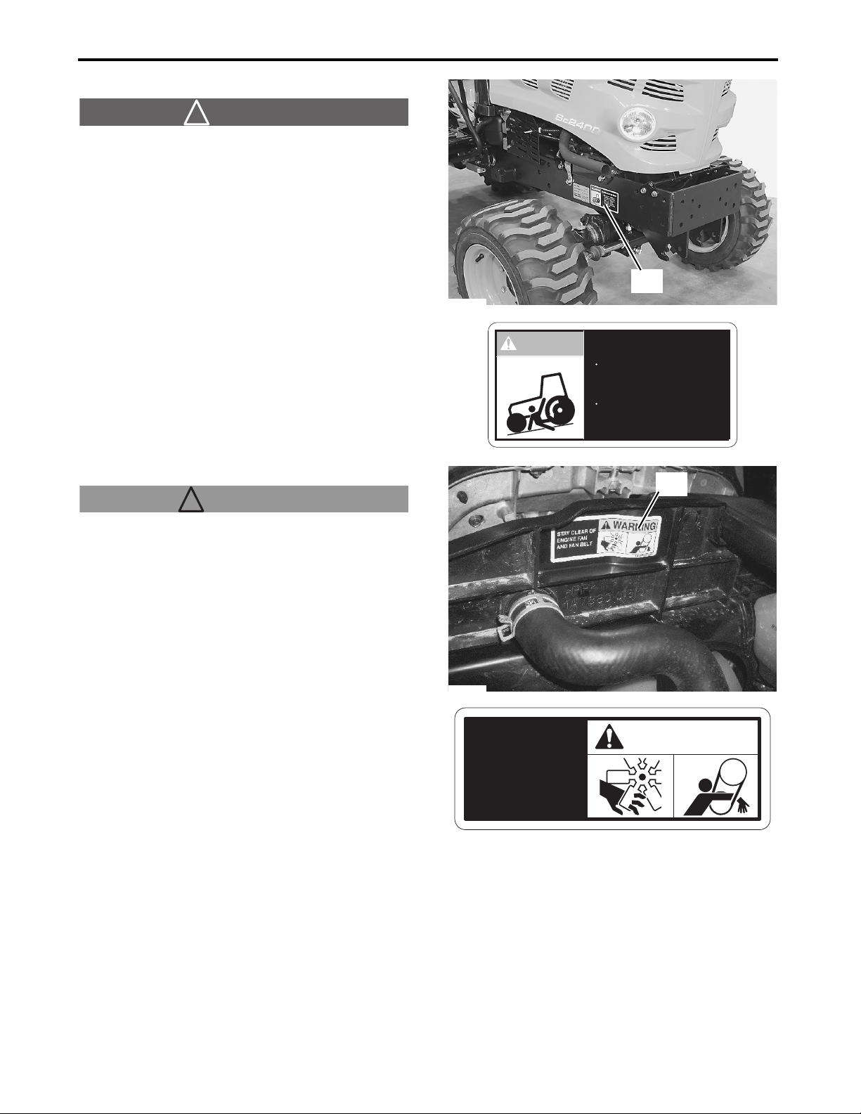
(A) CY-1A8160-65300
! DANGER
TO AVOID INJURY OR DEATH:
●Do not start engine by shorting across starter
terminals or bypassing safety start switch.
●Start engine only from seat with transmission and
PTO OFF.
(A)
P3014902
(B) CY-1A7880-65610
! WARNING
STAY CLEAR OF ENGINE FAN AND FAN BELT
P3014961
STAY CLEAR OF
ENGINE FAN
AND FAN BELT
DANGER
TO AVOID INJURY OR DEATH:
Do not start engine by
䇭shorting across starter
䇭terminals or bypassing
䇭safety start switch.
Start engine only from
䇭seat with transmission
䇭and PTO OFF.
1A8160-65300
(B)
WARNING
1-12
㪈㪘㪎㪏㪏㪇㪄㪍㪌㪍㪈㪇
Sc2400 Operator’s Manual
Page 22
1. SAFETY PRECAUTIONS
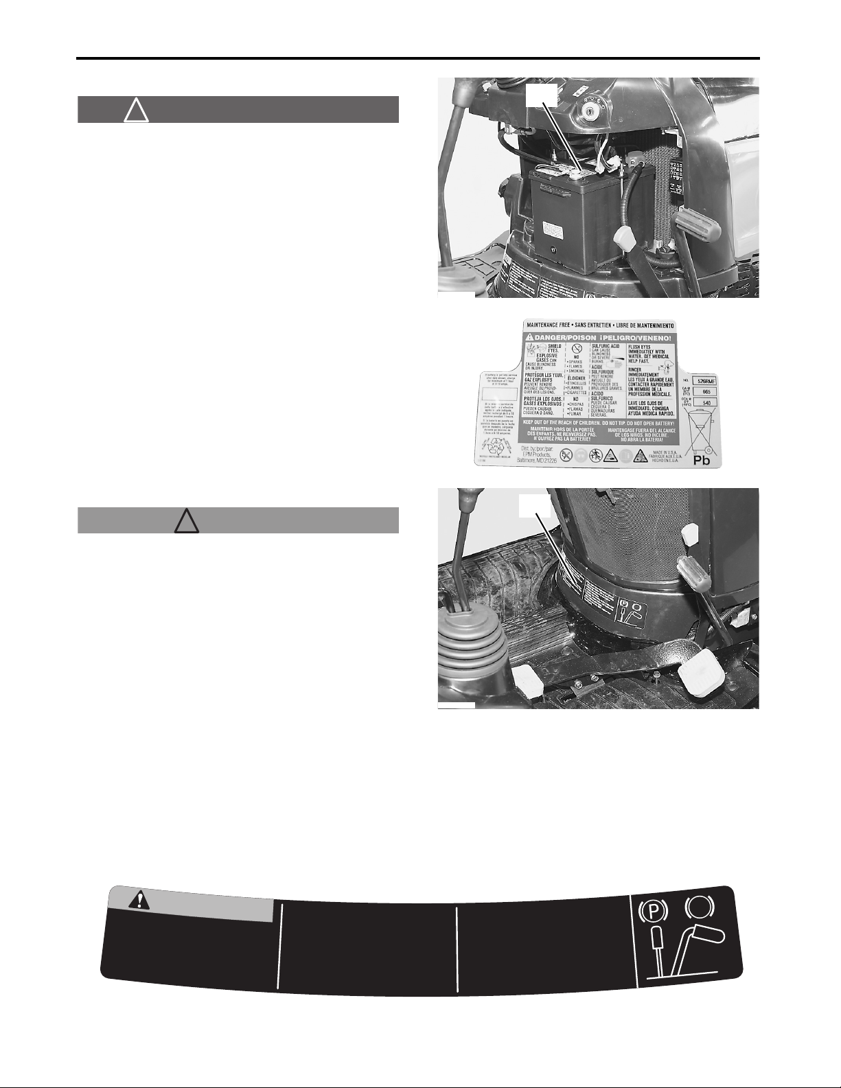
(C) CY-1A8160-51520
(C)
! DANGER/POISON (E)
●SHIELD EYES: EXPLOSIVE GASES CAN CAUSE
BLINDNESS OR INJURY.
●NO SPARKS, FLAMES, SMOKING.
●SULFURIC ACID CAN CAUSE BLINDNESS OR
SEVERE BURNS.
●FLUSH EYES IMMEDIATELY WITH WATER.
SEEK MEDICAL HELP RIGHT AWAY.
●KEEP OUT OF REACH OF CHILDREN. DO NOT
TIP.
●KEEP VENT CAPS TIGHT AND LEVEL.
P3014933
P3013722a
(D) CY-1A7880-65601
(D)
! WARNING
READ OPERATOR'S MANUAL
1. Do not operate the machine without guards
shields and safety devices in place and working.
2. Keep all riders off tractor during operation.
3. Make certain everyone is clear of machine before
starting engine or operation.
4. Keep hands, feet and clothing away from power-
driven parts.
5. Use seat belt.
6. Reduce speed when turning or operating around
hazards, on rough ground or steep slopes.
7. Do not allow operation of the machine by
untrained personnel.
8. Stop engine, lower implement to ground and lock park brake before dismounting.
9. Wait for all movement to stop before servicing machinery.
10. Remove key if leaving tractor unattended.
11. Securely support tractor and implements before working underneath.
12. On public roads use SMV emblem and hazard lights.
13. Do not jump if machine tips.
P3014940
WARNING
R
E
A
D
O
P
E
R
A
T
O
M
A
N
U
A
1
.
D
o
s
h
i
e
w
o
r
2
.
K
e
e
L
n
o
t
o
p
e
r
a
t
e
t
h
e
l
d
s
a
k
i
n
g
.
p
a
l
l
r
m
n
d
s
a
f
e
t
y
d
e
i
d
e
r
s
o
f
f
t
r
a
Sc2400 Operator’s Manual
R
a
c
h
i
n
e
w
i
t
h
o
v
i
c
t
o
u
c
e
s
i
n
p
l
a
c
e
r
d
u
r
i
n
g
o
p
e
d
n
u
o
r
g
o
3
.
M
a
k
e
c
e
r
t
a
i
n
e
v
e
r
y
o
n
e
i
s
c
l
e
a
r
e
o
f
n
i
m
h
a
b
e
f
o
r
e
s
t
a
r
t
i
n
g
e
n
g
i
n
e
o
r
4
.
K
e
e
p
h
a
n
d
s
,
'
S
t
g
a
n
r
a
p
o
5
.
U
s
6
.
R
u
d
t
i
o
e
a
r
d
s
a
r
o
s
l
o
7
.
D
o
n
u
.
n
t
f
w
e
r
-
d
r
i
v
e
n
p
e
s
e
a
t
b
e
l
t
.
d
u
c
e
s
p
e
e
d
u
n
d
h
a
z
a
r
d
p
e
s
.
n
o
t
a
l
l
o
w
o
r
p
a
i
n
e
d
p
e
r
s
o
o
e
e
t
a
n
d
c
l
o
t
h
a
r
t
s
.
w
h
e
n
t
u
r
n
i
s
n
,
o
n
r
o
u
g
h
e
r
a
t
i
o
n
o
f
t
h
n
n
e
l
.
c
p
e
r
.
a
t
n
i
o
i
n
g
a
w
a
m
y
o
r
f
g
o
r
o
p
g
e
n
r
i
t
a
g
r
o
u
n
p
d
e
o
e
r
t
s
e
m
a
c
y
h
b
i
n
e
n
e
p
o
t
S
.
8
c
o
l
d
n
a
o
f
t
i
a
W
.
9
n
i
c
i
v
r
e
s
o
m
e
R
.
0
1
r
u
c
e
S
.
1
1
e
r
o
f
e
b
u
p
n
O
.
2
1
r
a
z
a
h
o
n
o
D
.
3
1
r
e
w
o
l
,
e
n
i
g
e
k
a
r
b
k
r
a
p
k
r
g
v
e
d
e
m
e
v
o
m
l
l
a
y
r
e
n
i
h
c
a
m
a
e
l
f
i
y
e
k
e
t
t
r
o
p
p
u
s
y
l
n
u
g
n
i
k
r
o
w
u
s
d
a
o
r
c
i
l
b
.
s
t
h
g
i
l
a
m
f
i
p
m
u
j
t
t
t
n
e
m
e
l
p
m
i
d
e
r
o
f
e
b
p
o
t
s
o
t
t
n
.
o
t
c
a
r
t
g
n
i
v
d
n
a
r
o
t
c
a
r
.
h
t
a
e
n
r
e
d
e
V
M
S
e
s
s
p
i
t
e
n
i
h
c
.
g
n
i
t
n
u
o
m
s
i
e
r
o
f
e
b
.
d
e
d
n
e
t
t
a
n
u
r
m
.
s
t
n
e
m
e
l
p
m
i
d
n
a
m
e
l
b
1A788
5601
6
0-
1-13
Page 23
1. SAFETY PRECAUTIONS
(E) CY-1A7880-65630
IMPORTANT
12V DC OUTLET
1. DO NOT CONNECT A LIGHT OR LOAD OF
MORE THAN 120 WATTS.
2. DO NOT USE AS A CIGARETTE LIGHTER.
3. REMOVE PLUG FROM SOCKET WHEN NOT IN
USE.
4. DO NOT USE WHEN WET.
(E)
P3014958
IMPORTANT
12V DC OUTLET
1.DO NOT CONNECT A LIGHT OR LOAD OF MORE
THAN 120 WATTS.
2.DO NOT USE AS A CIGARETTE LIGHTER.
3.REMOVE PLUG FROM SOCKET WHEN NOT IN USE.
4.DO NOT USE WHEN WET.
1A7880-65630
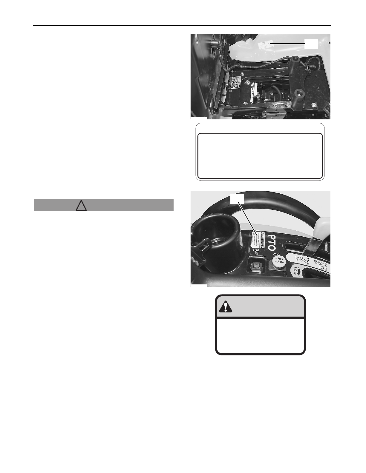
(F) CY-1A7880-65351
! WARNING
Only use PTO in reverse when there are no children
or others around
(F)
P3014940
WARNING
Only use PTO in
reverse when there
are no children or
others around
1-14
Sc2400 Operator’s Manual
Page 24
1. SAFETY PRECAUTIONS
(G) CY-1A7880-85190
! WARNING
This structure's protective capability may be impaired
by structural damage, overturn, or alteration.
If any of these conditions occur, this structure must
be replaced.
! WARNING
Use seat belt
P3014939
(G)
WARNING
This structure's
protective capability
may be impaired by
structural damage,
overturn, or alteration.
If any of these
conditions occur, this
structure must be
replaced.
(H) CY-198220-65621
! WARNING
AVOID INJURY FROM PTO
●Keep all shields in place
●Keep hands, feet and clothing away
●Operate only with 540 RPM
P3014938
WARNING
Use seat belt
001-7283-029
(H)
Sc2400 Operator’s Manual
WARNING
AVOID INJURY FROM PTO
Keep all shields in place
Keep hands,feet and
clothing away
Operate only with 540
RPM
1-15
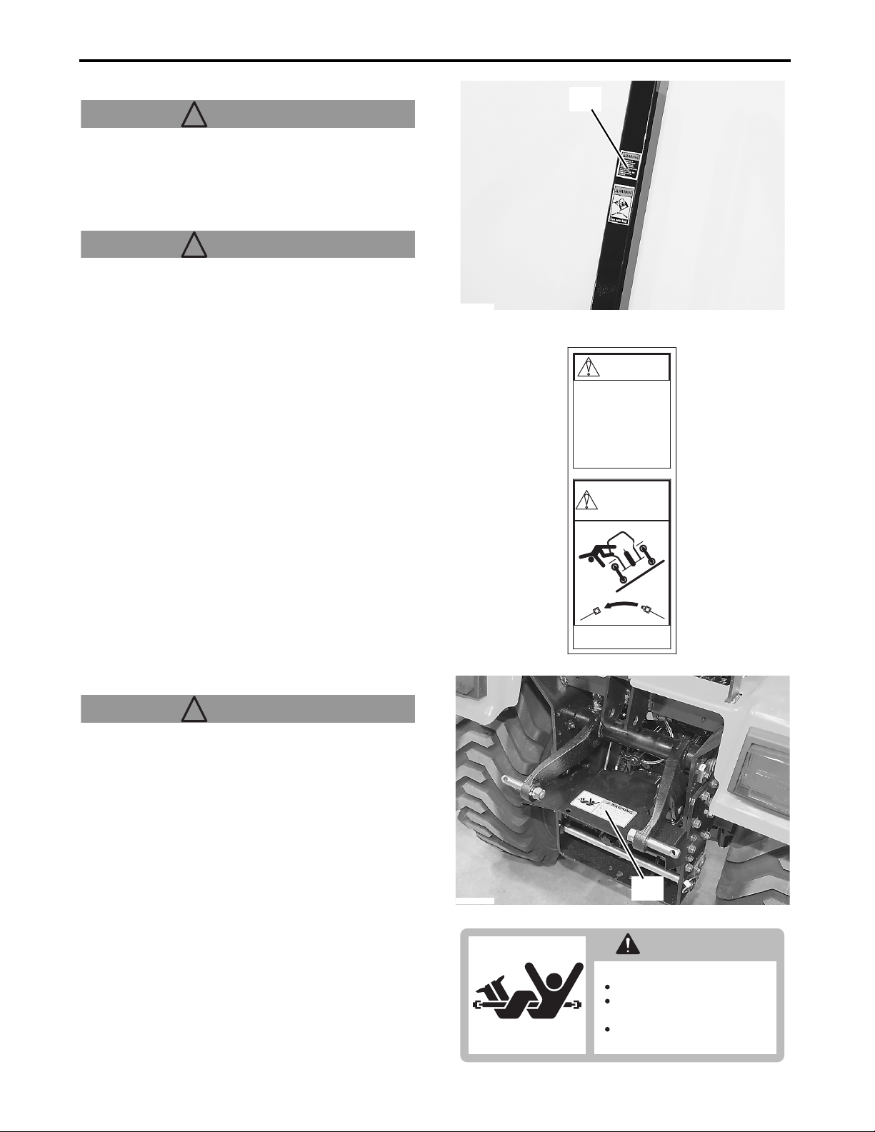
Page 25
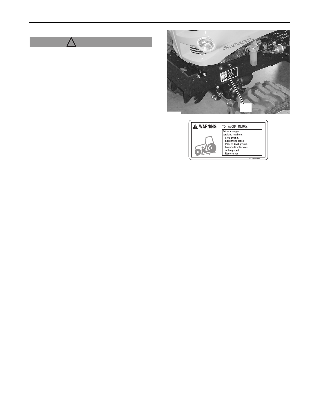
(I) CY-1A8160-65310
! WARNING
TO AVOID INJURY:
Before leaving or servicing machine,
●Stop engine.
●Set parking brake.
●Park on level ground.
●Lower all implements to the ground.
●Remove key.
1. SAFETY PRECAUTIONS
P3014959
(I)
1-16
Sc2400 Operator’s Manual
Page 26
2. SERVICE THE TRACTOR
2. SERVICE THE TRACTOR
Your Cub Cadet Yanmar dealer wants to remain
committed to the tractors our customers have
purchased and intends to support our customers in
fully developing the performance of their Cub Cadet
Yanmar tractors. After carefully studying this manual,
the customers themselves will be able to do a certain
portion of the regular maintenance work.
When parts/components or major service work is
needed, contact your local Cub Cadet Yanmar dealer
for technical assistance.
For information about the service work, contact your
local Cub Cadet Yanmar dealer. When ordering a
part/component, inform your local Cub Cadet
Yanmar dealer of the tractor and engine serial
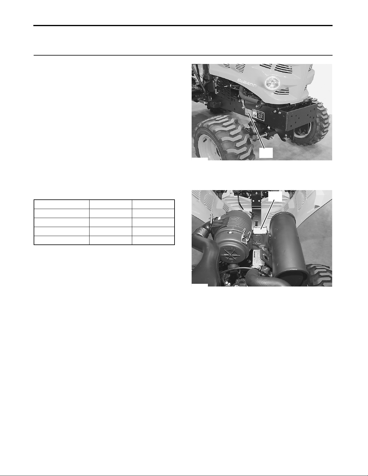
numbers. Find both serial numbers and enter them in
the following table.
P3014902
(A)
Type Serial No.
Tractor
Engine
Date of Purchase
Name of Dealer
(A) Tractor identification plate with tractor serial
number
(B) Engine serial number
(B)
P3014901
Sc2400 Operator’s Manual
2-1
Page 27

3. SPECIFICATIONS
3. SPECIFICATIONS
1. Specifications Table
Model Sc2400
Power Take Off (PTO) Power hp (kW) 16.5 (12.3)
Maker YANMAR
Model 3TNM72
Type
Number of Cylinders 3
Bore and Stroke in. (mm) 2.834 × 2.913 (72 × 74)
Total Displacement cu. in. (L) 55.1 (0.903)
Engine
Capacities
Dimensions
Weight (with Roll-Over Protective Structure (ROPS) and R4 Tires) lb. (kg) 1279 (580)
Gross Power hp (kW) 24.0 (17.9)
Net Power hp (kW) 20.2 (15.1)
Rated Revolution
High Idle Speed
Low Idle Speed
Maximum Torque
Battery 12V BP24 , CCA: 540 A
Fuel Diesel Fuel No.1-D , No.2-D
Fuel Tank US gal (L) Approximately 5.8 (22)
Engine Oil US qt. (L) Approximately 2.2 (2.1)
Engine Coolant US qt. (L) Approximately 3.4 (3.2)
Transmission Oil US gal (L) Approximately 2.0 (7.5)
Overall Length (without 3-Point Hitch) in. (mm) 82.7 (2100)
Overall Length (with 3P) in. (mm) 95.5 (2425)
Overall Width (with R4 Tires) in. (mm) 44.5 (1130)
Overall Height (with Roll-Over Protective Structure
(ROPS), R4 Tires)
Overall Height (with R4 Tires)
(Top of Steering Wheel)
Wheel Base in. (mm) 55.1 (1400)
Min. Ground Clearance (with R4 Tires) in. (mm) 7.5 (190)
Tread (with R4)
Front in. (mm) 34.6 (879)
Rear in. (mm) 32.2 (820)
-1
min
(rpm)
-1
min
(rpm)
-1
(rpm)
min
ft•lbs (N•m)
in. (mm) 71.5 (1817)
in. (mm) 49.9 (1267)
Indirect Injection, Vertical,
Water-Cooled, 4 Cycle Diesel
3200
3370
1150
40.3 (54.6)
3-1
Sc2400 Operator’s Manual
Page 28

3. SPECIFICATIONS
Traveling
System
Hydraulic Unit
Power Take Off
(PTO)
Ag (R1)
Tire
Clutch –
Steering Power Steering
Transmission
Drive Selected 4WD
Brake Wet plates
Minimum Turning Radius ft. (m) 7.2 (2.2)
Differential Lock Foot Pedal Control
Hydraulic Control System Type Position Control
Pump Capacity (main)
Pump Capacity (steering)
3-Point Hitch Limited Category I
Max. Lift Force
System Pressure psi (MPa) 1813 (12.5)
Type Electric Clutch
Rear
Mid
Turf (R3)
Industrial (R4)
Lift Point lb. (kg) 1036 (470)
24 in. Behind Lift Point lb. (kg) 661 (300)
Shaft Size SAE 1-3/8, 6-Splines
Type Independent
Speed/Engine
Shaft Size SAE 16/32, 15-Splines
Type Independent
Speed/Engine
Front 18 × 8.50-10
Rear 26 × 12.00-12
Front 18 × 8.50-10
Rear 26 × 12.00-12
Front 18 × 8.50-10
Rear 26 × 12.00-12
Hydrostatic Transmission,
2 Range Speeds
US gal/min
(L/min)
US gal/min
(L/min)
-1
min
(rpm)
-1
(rpm)
min
Approximately 3.4 (13.2)
Approximately 3.4 (13.2)
540 / 3111
2100 / 3338
2. Traveling Speeds (Reference)
Model Sc2400
Range Gear Lever mph km/h
Forward
Reverse
Sc2400 Operator’s Manual
Slow 0-5.8 0-9.4
Fast 0-9.0 0-14.6
Slow 0-3.5 0-5.6
Fast 0-5.4 0-8.7
3-2
Page 29
4. IMPLEMENT CAPACITIES
4. IMPLEMENT CAPACITIES
The Cub Cadet Yanmar tractor has been carefully tested in the configuration equipped with implements sold or
approved by Cub Cadet Yanmar and has proven to perform properly. Do not use any implement that has not
been sold or recommended by a Cub Cadet Yanmar dealer, or that fails to satisfy the specified values given
below. Never mount an implement that is not approved for the Cub Cadet Yanmar tractor. Using unapproved
implements could result in malfunction, failure, and damage to the tractor and/or implement, and increase the
possibility of injury to the operator or other people. The Cub Cadet Yanmar warranty does not cover any
malfunction or failure that results from use of an unapproved implement.
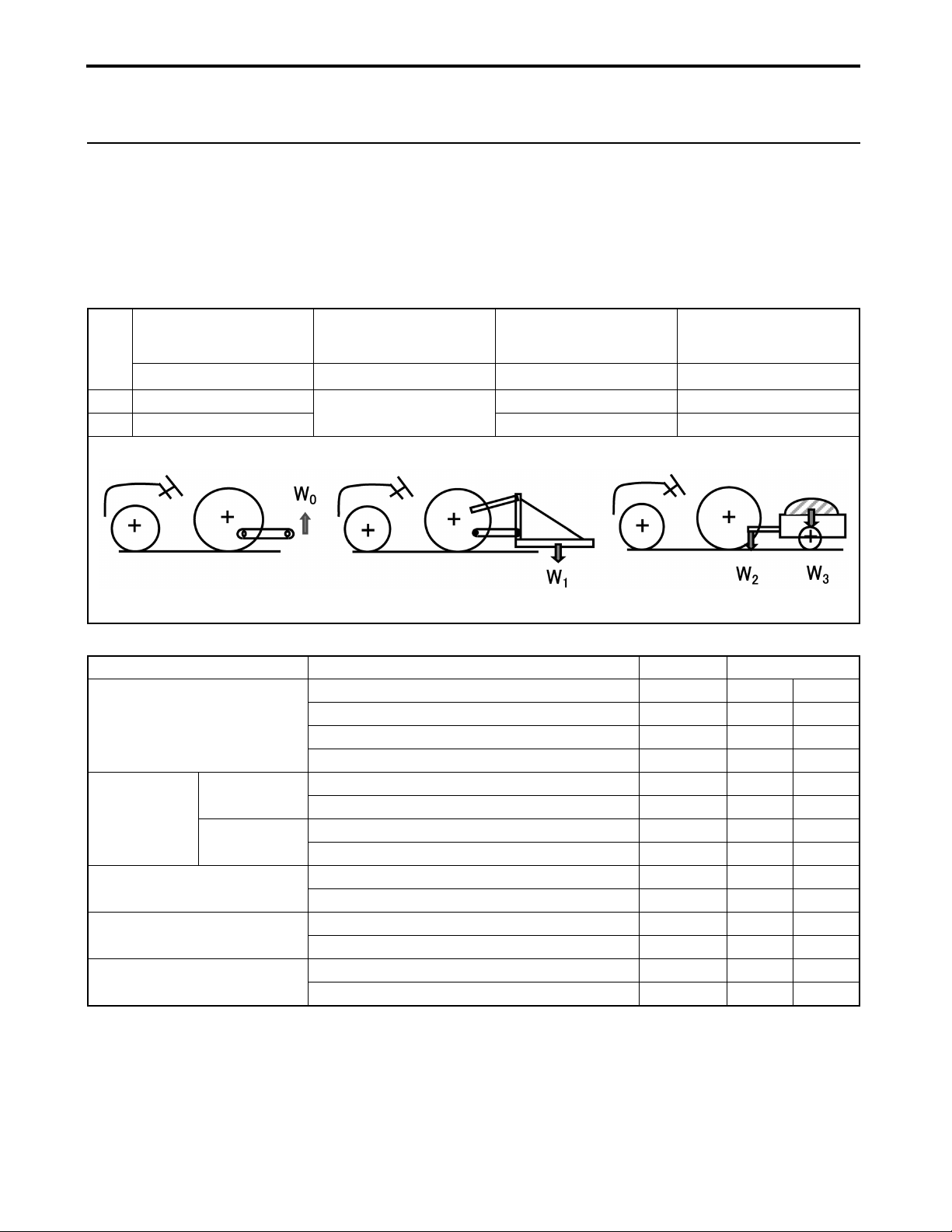
24in. Behind Lift Point
Maximum
Lifting Capacity
W
0
lb. 661
kg 300 150 300
A3013714a
Implement Remarks Unit Amount
Front - End Loader
Mid - Mount
Mower
Rear Mount
Rotary Tiller
Box Scraper (Box Blade)
Rear Blade
Implement Weight
W
1
As specified in the list
Maximum Lift Capacity (at Pivot) lb. (kg) 700 317
Maximum Overhang (Pivot - Front Tire Center) in. (mm) 40 1022
Maximum Weight lb. (kg) 441 200
Maximum Oil Pressure psi (MPa) 1885 13
Maximum Cutting Width in. (mm) 60 1524
Maximum Weight lb. (kg) 254 115
Maximum Cutting Width in. (mm) 48 1219
Maximum Weight lb. (kg) 351 159
Maximum Tilling Width in. (mm) 42 1067
Maximum Weight lb. (kg) 342 155
Maximum Cutting Width in. (mm) 48 1219
Maximum Weight lb. (kg) 254 115
Maximum Cutting Width in. (mm) 60 1524
Maximum Weight lb. (kg) 176 80
below.
Maximum Vertical
Hitch Load
W
2
331 661
Towing Capacity
Maximum
W
3
NOTE
●Backhoes cannot be attached.
4-1
Sc2400 Operator’s Manual
Page 30
5. NAMES AND FUNCTIONS OF COMPONENTS
5.
NAMES AND FUNCTIONS OF COMPONENTS
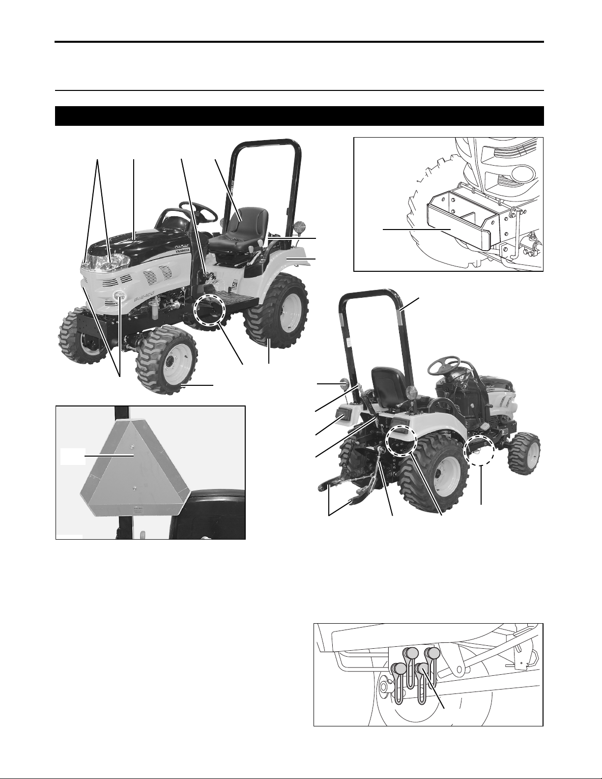
1. Overview
(1)
(2)
(3)
(4)
(5)
(6)
(11)
3014925a
(12)
P3014903
(10)
(8)
(9)
(21)
P3014904
(1) Headlights
(2) Hood
(3) Fuel inlet
(4) Seat
(5) Seat belt
(6) Fender
(7) Rear tires
(8) Mid-Power Take Off (PTO)
(9) Front tires
(10) Work lights
(11) Front weight hitch (Option)
(12) Roll-Over Protective Structure (ROPS)
(13) Hydraulic quick couplers (Option)
(14) 12V DC outlet (for additional rear work light)
(15) Rear Power Take Off (PTO) shaft
Sc2400 Operator’s Manual
(7)
(20)
(19)
(18)
(17)
P3014905
(16)
(16) Lower links
(17) Top link retainer
(18) Tail lights
(19) Top link
(20) Turn signal/Hazard lights
(21) Slow Moving Vehicle (SMV) emblem
3014906
(15)
5-1
(14)
(13)
(13)
Page 31
5. NAMES AND FUNCTIONS OF COMPONENTS
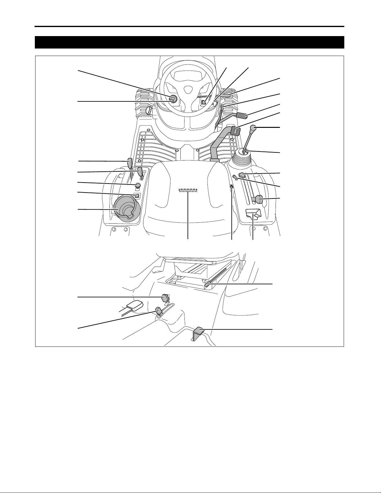
2. Operator Station Controls
(21)
(20)
(19)
(18)
(17)
(16)
(15)
3014903
(14)
(1)
(13)
(2)
(3)
(4)
(5)
(6)
(7)
(8)
(9)
(10)
(11)
(12)
(25)
(24)
3014904
(1) Hazard lights button switch
(2) Starter key switch
(3) Throttle control lever
(4) Parking brake lever
(5) Brake pedal
(6) Forward and reverse drive pedal
(7) Implement control lever (Option)
(8) Implement lock lever (Option)
(9) Position stop knob
(10) Cruise control lever
(11) 3-point hitch control/cutting height adjustment
lever
(12) Storage compartment
(13) 12V DC outlet
(22)
(23)
(14) Hydro Static Transmission (HST)
pressure release lever
(15) Cup holder
(16) Reverse-override-switch
(17) Power Take Off (PTO) switch
(18) Range gear lever
(19) Mid-/Rear Power Take Off (PTO) select lever
(20) Turn signal switch
(21) Headlight/work light switch
(22) Seat adjustment lever
(23) Differential lock foot pedal
(24) 4-wheel drive lever
(25) Hydraulic flow control/stop knob
5-2
Sc2400 Operator’s Manual
Page 32

5. NAMES AND FUNCTIONS OF COMPONENTS
■ Function of Components
(1) Hazard lights button switch
Depress the red button to turn the hazard lights ON.
Pressing this button will cause the button to light up
and the hazard lights at the rear of tractor to flash.
(The hazard lights remain flashing even when the
starter key switch is in the OFF position. Remember
that allowing the turn signal/hazard lights to flash for
an extended period can lead to loss of battery
voltage.)
(a) ON
(b) OFF
(2) Starter key switch
This switch is used to start and stop the engine.
(a) (b)
3013729
(A) OFF position:
The engine must be off.
(B) ON position:
When the key has been turned to this position,
the engine oil pressure warning light and the
alternator/battery charging light and the engine
coolant warning light will illuminate.
(C) START position:
When the key is turned to this position, the starter
starts turning the flywheel and then the engine
begins to run. Once the engine has started,
release the key.
(D) Preheating position:
Preheating time should be determined according to
outside air temperature. For details, see the table
below.
Temperature (°F (°C)) Preheating Time (sec.)
Over 32 (0) 2 to 3
Below 32 (0) 4
3014907a
(D)
(A)
(B)
(C)
(A) OFF position
(B) ON position
(C) START position
(D) Preheating position
Sc2400 Operator’s Manual
5-3
Page 33

5. NAMES AND FUNCTIONS OF COMPONENTS
(3) Throttle control lever
Use the throttle control lever to change the engine
speed. While monitoring the tachometer, change the
engine speed as required.
(A) Throttle control lever
(a) To increase the engine speed:
pull the throttle control lever backward.
(b) To decrease the engine speed:
push the throttle control lever forward.
(4) Parking brake lever
This lever is used when parking the tractor.
(A) Parking brake lever
(a) To engage the parking brake: Fully pull the
parking brake lever backward.
(b) To unlock the parking brake: Fully push the
parking brake lever forward.
3014903e
(A)
(b)
(A)
(a)
(b)
(a)
(5) Brake pedal
This pedal is used to stop and park the tractor.
(A) Brake pedal
(a) To apply the brakes: Depress the brake pedal.
(b) To release the brakes: Release foot from the
brake pedal.
3014916f
3014916f
(A)
(b)
(a)
5-4
Sc2400 Operator’s Manual
Page 34

5. NAMES AND FUNCTIONS OF COMPONENTS
(6) Forward and reverse drive pedal
The tractor accelerated speed depends on how far
the drive pedal is pressed.
(A) To move forward:
Depress the forward side of the forward and
reverse drive pedal.
(B) To move backward:
Depress the reverse side of the forward and
reverse drive pedal.
(A) Forward side of the forward and reverse drive
pedal
(B) Reverse side of the forward and reverse drive
pedal
IMPORTANT
●When the drive pedal is released, the transmission
will automatically return to the NEUTRAL position.
3014916c
(B)
(A)
(7) Implement control lever (Option)
The implement control valve has a float position.
When the implement control valve is in this position,
implements such as blades or front loaders, lowered
to the operating position, are allowed to follow
ground contours.
Push the implement control lever forward beyond the
valve detent position to the float position.
(a) Lower
(b) Float
(c) Dump
(d) Dump faster
(e) Raise the implement
(f) Curl
IMPORTANT: Avoid damage.
●Prevent damage or contamination to the female
quick couplers. ALWAYS leave the color-coded
hose ends connected to the couplers when the
couplers are not in use.
NOTE
●When the implement control lever is released, it
returns to its NEUTRAL position.
(f)
(b)
(a)
(c)
(d)
(e)
1A7880-65410
Sc2400 Operator’s Manual
5-5
Page 35

5. NAMES AND FUNCTIONS OF COMPONENTS
(8) Implement lock lever (Option)
When fixing the implement control lever at its
NEUTRAL position, use the implement lock lever.
(A) Implement control lever
(B) Implement lock lever
(A)
IMPORTANT: Avoid damage.
●Do not attempt to operate the implement control
lever when the implement control lever has been
locked.
●When the implement control lever has been locked
with the implement lock lever, move the implement
control lever with light force to ensure that it has
been securely locked.
(a) To unlock the implement control lever:
Pull up the implement lock lever.
(b) To lock the implement control lever:
Push down the implement lock lever when the
implement control lever is in its NEUTRAL
position.
(9) Position stop knob
This knob is used to secure the implement installed
with the 3-point hitch in its raised position, or to limit
the range of operation of the 3-point hitch control/
cutting height adjustment lever.
3014903n
(a)
(B)
(b)
(A) Position stop knob
(10)Cruise control lever
The cruise control is a feature that regulates forward
tractor travel to a specific speed.
(A) Cruise control lever
3014918e
(A)
5-6
3014903m
(A)
Sc2400 Operator’s Manual
Page 36
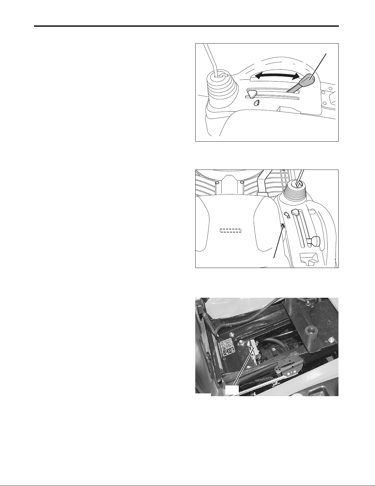
5. NAMES AND FUNCTIONS OF COMPONENTS
(11)3-point hitch control/cutting height adjustment lever
Use the 3-point hitch control/cutting height
adjustment lever, when raising or lowering the midor rear mounted implement.
(A) 3-point hitch control/cutting height
adjustment lever
(a) Moving the 3-point hitch control/cutting height
adjustment lever forward will lower the
implement.
(b) Moving the 3-point hitch control/cutting height
adjustment lever backward will raise the
implement to raise higher.
(13)12V DC outlet
This can be used as a power source for electrical
goods.
(A) 12V DC outlet
3014918e
(a)
(A)
(b)
3014903o
(14)Hydro Static Transmission (HST) pressure release lever
Hydraulic pressure in the Hydro Static Transmission
(HST) brakes the axles when the engine is not
running, so that the tractor cannot be moved.
When the hydraulic pressure in the transmission is
released by pressing the Hydro Static Transmission
(HST) pressure release lever, the tractor can be
moved.
(A) Hydro Static Transmission (HST) pressure
release lever
P3014906
(A)
(A)
Sc2400 Operator’s Manual
5-7
Page 37

5. NAMES AND FUNCTIONS OF COMPONENTS
(16)Reverse-override-switch
Normally, reversing the tractor stops the Mid-Power
Take Off (PTO) and the Rear Power Take Off (PTO).
To drive the Power Take Off (PTO) while reversing
the tractor, use the reverse-override-switch.
(A) Reverse-override-switch
(17)Power Take Off (PTO) switch
This switch is used to rotate the Power Take Off
(PTO).
(A) Power Take Off (PTO) switch
(a) Turn off: Push the switch.
(b) Turn on: Pull the switch.
(A)
3014919d
(A)
(18)Range gear lever
Use the range gear lever to select the speed that
best suits the intended operation.
(A) Range gear lever
(a) SLOW : Used for heavy-load operation.
Low traveling speed.
(b) FAST : Used for light-load operation.
High traveling speed.
3014919g
(a) (b)
3014926
(A)
(a)
5-8
3014919a
(b)
Sc2400 Operator’s Manual
Page 38

5. NAMES AND FUNCTIONS OF COMPONENTS
(19)Mid-/Rear Power Take Off (PTO) select lever
This lever is used to select the Mid- or Rear Power
Take Off (PTO), depending upon the implement
being used.
(c)
(b)
(A)
(A) Mid-/Rear Power Take Off (PTO) select lever
(a) Operating the Mid-Power Take Off (PTO) alone
(b) Operating the Mid-Power Take Off (PTO) and the
Rear Power Take Off (PTO) at the same time
(c) Operating the Rear Power Take Off (PTO) alone
(20)Turn signal switch
(21)Headlight/work light switch
Use the blue lever to turn ON/OFF the headlights
and work lights. Turning the blue lever to the (b)
position illuminates the headlights and turning it to
the (c) position illuminates the work lights and
headlights at the same time.
• The yellow lever is a turn signal switch.
• Move the turn signal switch right to signal a right
turn.
• Move the turn signal switch left to signal a left
turn.
• The tail light illuminates while the turn signal light
is illuminated or blinked, the tail light similarly
illuminates or flashes.
3014919e
(A)
A3014901
(a)
(a) (b) (c)
(B)
(A) Blue lever (Headlight/work light switch)
(B) Yellow lever (Turn signal switch)
(a) OFF
(b) Headlights ON
(c) Headlights and work lights ON
(d) To signal a left turn, move the lever to left
(e) To signal a right turn, move the lever to right
(22)Seat adjustment lever
See “Adjust the Operator's Seat” on page 7-2.
(23)Differential lock foot pedal
See “Differential Lock” on page 8-13.
Sc2400 Operator’s Manual
5-9
A3014902
(d)
(e)
Page 39

5. NAMES AND FUNCTIONS OF COMPONENTS
(24)4-wheel drive lever
In the 4-wheel drive mode, all the four wheels are
powered to obtain better traction on difficult-to-travel
ground.
The 4-wheel drive lever can be set to the ON or OFF
position only when the tractor is at a standstill.
(A)
(A) 4-wheel drive lever
(a) 4-wheel drive mode
(b) 2-wheel drive mode
IMPORTANT: Avoid damage.
●ALWAYS keep the 4-wheel drive lever in the OFF
position when traveling on a paved surface.
●ALWAYS disengage the 4-wheel drive lever when
not needed to prevent premature wear of the front
tires.
●NEVER install tire chains to the front wheels.
Chains will hit and can damage the tractor.
●If disengaging the 4-wheel drive lever is difficult,
stop the tractor, turn the steering wheel right and
left several times. Then attempt to disengage the
4-wheel drive lever again.
●To minimize tire wear, drive in the 4-wheel drive
mode only when absolutely necessary. Driving the
tractor on a paved road in the 4-wheel drive mode
can accelerate wear of the tires.
●To obtain better traction, keep the front tires at the
maximum allowable pressure.
●When the 4-wheel drive lever is in the ON position,
braking will apply to all four wheels.
(b)
(a)
3014904b
(25)Hydraulic flow control/stop knob
The lowering speed of the lower link is governed by
the position of the hydraulic flow control/stop knob.
Also, this knob is used to stop the lower link at an
intended position.
(A) Hydraulic flow control/stop knob
(a) Turning the knob clockwise will cause the
lowering speed to decrease.
Tighten the knob by fully turning clockwise to stop
the lower link.
(b) Turning the knob counterclockwise will cause the
lowering speed to increase.
5-10
3014904d
(b)
(a)
(A)
Sc2400 Operator’s Manual
Page 40

5. NAMES AND FUNCTIONS OF COMPONENTS
3. Instrument Panel, Switches and Hand Controls
(1)
(7)
(6)
(5)
(4)
3014905
(2)(3)
(1) Tachometer
This meter indicates the current engine speed in
increments of 100 min
(2) Fuel gauge
This gauge indicates level of fuel in the fuel tank,
while the starter key switch is in the ON position.
(3) Hour meter
This meter indicates the total accumulated operating
hours. This indication is based on the assumption
that the engine runs at a speed of 3300 min
(4) Alternator/battery charging light
This light remains lit when the starter key switch is in
the ON position and the engine is OFF.
IMPORTANT
●If this light illuminates while the engine is running,
the power generated by the alternator is too low.
Fully pull the throttle control lever backward and
increase the engine speed. If the light still remains
lit, immediately stop the engine and contact your
local Cub Cadet Yanmar dealer for technical
assistance.
(5) Engine oil pressure warning light
This light remains lit when the starter key switch is in
the ON position and the engine is OFF.
IMPORTANT
●If this light illuminates while the engine is running,
the engine oil pressure is too low. Immediately stop
the engine and contact your local Cub Cadet
Yanmar dealer for technical assistance.
Sc2400 Operator’s Manual
-1
(rpm).
-1
(rpm).
(6) Preheater pilot light
This light illuminates when the engine starter key
switch is turned to the preheating position.
Preheating time should be determined according to
outside air temperature. For details, see the table
below.
Temperature (°F (°C)) Preheating Time (sec.)
Over 32 (0) 2 to 3
Below 32 (0) 4
(7) Engine coolant warning light
This light illuminates when engine coolant
temperature becomes abnormally high.
IMPORTANT
●If the engine coolant warning light does turn on,
reduce the load on the tractor immediately, run the
engine at an idle until the light turns off, and shut
off the engine. Wait until the engine has cooled off
completely, and check to see that there is:
(1) Sufficient coolant in the radiator and reserve
tank
(2) No clogging of the radiator fins and screen
(3) Sufficient tension in the fan belt
See “14. PERIODIC SERVICE” for more
information on maintenance procedures.
●If the coolant warning light turns on again even
after being sure of the checkpoints above, shut off
the engine immediately and contact your local Cub
Cadet Yanmar dealer.
5-11
Page 41

6. PRE-OPERATION CHECK
6. PRE-OPERATION CHECK
1. Pre-Operation Check
●Check the tractor for damage, excessive wear, cracks, missing parts,
exposed wiring and any other problems, including leaks.
●Check the joints and connections for looseness.
●Check that all the lights illuminate.
●Check that all the safety-alert decals are in correct position.
If any problem is detected, contact your local Cub Cadet Yanmar dealer,
and correct the problem. NEVER operate the tractor when a problem has
been indicated.
2. Precautions before the Operation
●ALWAYS be aware of the limitations of the performance of the tractor.
●Operate the tractor, keeping in mind “SAFETY FIRST!”.
3. Routine Check
●Check the safety features.
●Check the tire pressure.
●Check that the remaining diesel fuel is sufficient for the intended
operation.
●Check the engine oil level.
●Check the transmission/hydraulic oil level.
●Check the coolant level.
●Remove grass clippings and debris from the tractor.
●Clean the air cleaner element.
●Check the tractor for any leaks such as oil, coolant and fuel.
●Check the radiator for possible blockage.
●Check the retractable seat belt and the Roll-Over Protective Structure
(ROPS) for any problem.
If any problem is detected, contact your local Cub Cadet Yanmar dealer
and correct the problem.
4. Prevent Damage to the Plastic Surfaces and Painted Surfaces
●Only wipe off the tractor after washing.
●Chemical agents such as pesticides can damage the plastic surfaces and
painted surfaces. NEVER spray chemical agents near the machine.
●NEVER spill diesel fuel onto the tractor. Diesel fuel can damage the
plastic surfaces and painted surfaces. ALWAYS wipe up spilled diesel
fuel immediately.
6-1
Sc2400 Operator’s Manual
Page 42

7. OPERATE THE ENGINE
7. OPERATE THE ENGINE
! WARNING
NEVER run or idle the engine in a
confined area that is poorly ventilated or
not ventilated at all. The engine emits
carbon monoxide as that is colorless,
odorless and can cause death.
ALWAYS remain seated in the operator's station
when starting the engine or actuating the levers or
controls.
Always ensure that your foot is removed from the
forward and reverse pedal, the parking brake is
engaged and Power Take Off (PTO) switch is in the
OFF position before the engine is started.
While operating the tractor, make sure to keep the
seat belt fastened with the Roll-Over Protective
Structure (ROPS) equipped. This will reduce the
possibility of injury or death in the event of an
accident such as an overturn or roll-over.
Start the engine of your tractor only with the starter
key switch. NEVER attempt to start the tractor engine
by short-circuiting across its terminals with a jumper
or by bypassing the safety start switch.
Before operation, make sure that all the safety
features are functioning correctly. Make corrections
as necessary.
Sc2400 Operator’s Manual
7-1
Page 43

7. OPERATE THE ENGINE
1. Start the Engine
1. Open the fuel shut-off valve.
■ Opening/Closing the Fuel Shut-Off
Valve
●To open the valve, turn the valve lever to the
vertical position.
●To close the valve, turn the valve lever to the
horizontal position.
(A) Valve lever
(O) Open
(C) Close
2. Sit on the seat.
■ Adjust the Operator's Seat
1. Engage the parking brake securely and stop the
engine.
2. Sit on the seat.
3. Pull the seat adjustment lever to the left.
4. Move the seat forward and backward to find the
optimal position and then release the seat
adjustment lever.
5. While remaining seated, confirm that various
control levers can be comfortably operated. If any
control lever cannot be operated comfortably,
readjust the seat position as necessary.
3014908a
3014904a
(C)
(O)
(A)
(A)
(A) Seat adjustment lever
IMPORTANT
●After adjusting the seat position, always make sure
that the seat is securely locked in place.
■ Fasten the Retractable Seat Belt
! WARNING
! WARNING
Avoid injury:
●While operating the tractor, make sure to keep the seat belt fastened with the Roll-Over Protective Structure (ROPS) equipped. This will reduce the possibility of injury or death in the event of an accident such as an overturn or roll-over.
●NEVER use the retractable seat belt when operating the tractor without the Roll-Over Protective Structure (ROPS).
7-2
Sc2400 Operator’s Manual
Page 44

7. OPERATE THE ENGINE
1. Draw out the right and left segments of the
retractable seat belt from the retracted positions
on both sides of the operator's seat.
2. Connect both segments of the belt with the
buckle, being careful to avoid twisting of the belt,
adjust the belt length, being suitable for the
operator.
(A) Buckle
(a) Adjust the belt length
! WARNING
! WARNING
●If the retractable seat belt is situated far away
from the operator's abdominal area, a
dangerous situation can be present in the event
of an accident. ALWAYS ensure that the
retractable seat belt is in the lowest possible
position to the operator's abdominal area.
●The retractable seat belt must be used by the operator only. NEVER use the retractable seat belt for two or more persons or to hold an object to the operator.
(A)
A3013712
(a)
3. Remove foot from the forward and
reverse drive pedal and set the pedal
to the NEUTRAL position.
NOTE
●With the parking brake engaged, the forward and reverse drive pedal is locked in the NEUTRAL position.
4. Engage the parking brake securely.
■ Engage the Parking Brake
1. Fully depress the brake pedal.
2. Fully pull the parking brake lever backward to
engage the parking brake securely.
3. Remove foot and make sure that the brake is fully
locked.
NOTE
●Applying the parking brake engages the differential
lock at the same time.
(A) Brake pedal
(B) Parking brake lever
3014916a
(A)
(B)
IMPORTANT: Avoid damage.
●NEVER step on the forward and reverse drive pedal while the parking brake is engaged.
Sc2400 Operator’s Manual
7-3
Page 45

7. OPERATE THE ENGINE
5. Set the range gear lever to the Slow
position.
(A) Range gear lever
(a) Slow position
(A)
(a)
3014919a
6. Turn off the Power Take Off (PTO)
switch.
Push in and set the Power Take Off (PTO) switch to
the OFF position.
(A) Power Take Off (PTO) switch
(a) OFF position
(b) ON position
7. Fully push the 3-point hitch control/
cutting height adjustment lever
forward to the lowest position and
lower the mid- or rear mounted
implements to the ground.
(A)
3014919g
(a) (b)
3014926
(A)
(a)
(A) 3-point hitch control/cutting height
adjustment lever
(a) Lowest position
! WARNING
! WARNING
●In order to prevent a turnover accident, completely lower the implements to the ground.
7-4
3014918b
Sc2400 Operator’s Manual
Page 46

7. OPERATE THE ENGINE
8. If the tractor has any implements that
use the implement control lever, lower
them to the ground. Then, set the
implement control lever to the
NEUTRAL position and push in the
implement lock lever to lock.
(A) Implement control lever
(B) Implement lock lever
(a) Lower the implement to the ground
(a)
(A)
9. Set the throttle control lever about
halfway.
(A) Throttle control lever
(a) To increase the engine speed, pull the throttle
control lever backward.
(b) To decrease the engine speed, push the throttle
control lever forward.
10.Insert the key into the starter key hole
and turn the key to the ON position.
(A) ON position
3014903d
3014903e
(B)
(b)
(A)
(a)
(A)
Sc2400 Operator’s Manual
3014907a
7-5
Page 47
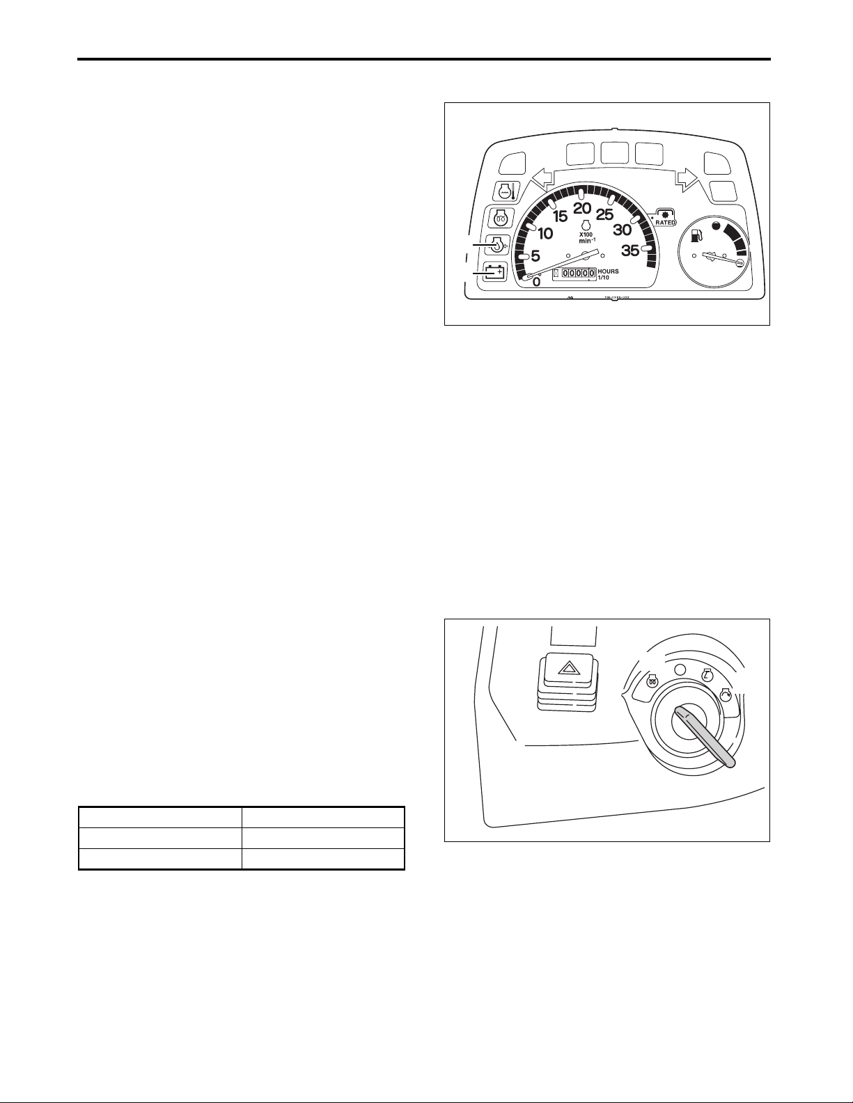
7. OPERATE THE ENGINE
■ Check the Lights on the Instrument Panel
When the key is turned to the ON position:
1. The engine oil pressure warning light turns ON.
2. The alternator/battery charging light turns ON.
(A) Engine oil pressure warning light
(B) Alternator/Battery charging light
NOTE
●The engine oil pressure warning light turns off within
5 seconds after the engine is started.
●The alternator/battery charging light turns off within
10 seconds after the engine is started.
IMPORTANT: Avoid damage.
●When the engine oil pressure warning light does not turn OFF within 10 seconds after the engine is started, the engine oil pressure is too low. Immediately stop the engine and contact your local Cub Cadet Yanmar dealer for technical assistance.
●When the alternator/battery charging light does not
turn OFF within 15 seconds after the engine is
started, the power generated by the alternator is
too low. Increase the engine speed to its maximum
so as to increase the power. If the light still remains
lit, immediately stop the engine and contact your
local Cub Cadet Yanmar dealer for technical
assistance.
(A)
(B)
3014905
11.Turn the key to the PREHEATING
position and energize the glow plug to
preheat the engine.
(A) Preheating position
(B) START position
Preheating time should be determined according to
outside air temperature. For details, see the table
below.
Temperature (°F (°C)) Preheating Time (sec.)
Over 32 (0) 2 to 3
Below 32 (0) 4
(A)
(B)
3014907
7-6
Sc2400 Operator’s Manual
Page 48

7. OPERATE THE ENGINE
NOTE
●While turning the key to the preheating position, the
preheater pilot light turns ON. Also, the engine oil
pressure warning light and the alternator/battery
charging light turn ON.
(A) Preheater pilot light
12.Turn and hold the key to the START
position. After the engine is
successfully started, release the key.
IMPORTANT: Avoid starter damage.
●Do not hold the key in the START position for more than 15 seconds at a time. Any longer attempt will overheat the starter motor.
●If the engine is difficult to start at a low temperature etc., hold the key in the START position for 30 seconds. If the engine fails to start, wait at least 30 seconds before the second attempt to allow for battery voltage recovery.
●If the engine still fails to start with four consecutive attempts, the starter may be not functioning. (See “Chapter 17. TROUBLESHOOTING” ).
(A)
3014905
13.After the engine has started, warm up
the engine for 5 minutes at 2000 to
2400 min-1(rpm) without loading.
■ Warm Up the Engine in Cold Weather
In cold weather, warm up the engine for much longer than 5 minutes so that the hydraulic system shows its performance. For the appropriate warming up time, see the table below.
Temperature (°F (°C)) Warming-up Time (min.)
Over 32 (0) At least 5
32 to 14 (0 to –10) 5 to 10
14 to –4 (–10 to –20) 10 to 15
Below –4 (–20)
NOTE
●The engine may run slightly louder and emit pale blue exhaust during warming-up. This is considered normal operation. The amount of pale blue exhaust varies depending on the ambient temperature.
●Idling the engine for a long time causes waste of fuel and carbon accumulation in the engine.
More than 15
Sc2400 Operator’s Manual
7-7
Page 49

7. OPERATE THE ENGINE
2. Shut Down the Engine
1. Remove foot from the forward and
reverse drive pedal.
2. After the tractor has completely
stopped, turn off the Power Take Off
(PTO) switch, lower the implement (if
installed) to the ground and then
engage the parking brake securely.
3. Run the engine at a lowest possible
speed for at least 2 minutes.
(B)
4. Turn the key to the OFF position.
5. Remove the key from the starter key
switch.
6. Make sure that the engine and other
components have stopped running.
NEVER leave the operator’s seat
while any components are running.
(A) Forward and reverse drive pedal
(B) Throttle control lever
(C) Power Take Off (PTO) switch
3013703a
3014919c
(A)
(C)
7-8
Sc2400 Operator’s Manual
Page 50

7. OPERATE THE ENGINE
3. Restart a Stalled Engine
IMPORTANT: Avoid engine damage.
●If the engine stalls while operating under load,
immediately restart the engine to prevent overheating of the engine.
1. Engage the parking brake securely.
2. Set the range gear lever to the slow
position.
(A) Range gear lever
(a) Slow position
3. Turn off the Power Take Off (PTO)
switch.
! WARNING
! WARNING
●To prevent a possible accident, fully lower all
the implements to the ground.
(A) Power Take Off (PTO) switch
(a) OFF position
(A)
(a)
3014919a
(a)
(A)
3014919b
4. Restart the engine.
Resume the operation; or run the
engine for 1 to 2 minutes at the lowest
possible running speed, and then
stop the engine.
Sc2400 Operator’s Manual
7-9
Page 51

8. OPERATE THE TRACTOR
8. OPERATE THE TRACTOR
! WARNING
ALWAYS decrease tractor speed before turning,
when traveling on a rough terrain or before stopping
to prevent roll-over.
Do not attempt to turn with the differential lock
engaged. Attempting to turn the tractor while the
differential lock is engaged can lead to a roll-over.
ALWAYS remain alert to behaviors of children when
operating the tractor because they are usually very
curious about moving machines.
ALWAYS remember that children may have moved
from a point you last viewed them.
Accident Hazard
ALWAYS stay clear of ditches, holes, embankments
or ponds. A roll-over can occur more easily if the
ground is soft or wet. Before entering an area
covered with tall grass, walk the area to detect any
obstacles.
ALWAYS be extremely careful about the direction
you are traveling and avoid obstacles. Remain alert
when you are approaching the end of a row, trees or
any obstacle.
ALWAYS maintain good communication with all
others working the same area before and during
operation of the tractor.
Do not get in or out of the moving tractor.
ALWAYS keep children off the work area, and a
person other than the operator should always watch
them.
If any child enters the current work area, stop your
tractor immediately.
NEVER allow children to ride the moving tractor.
They may tamper the controls or can fall off the
tractor and be run over by the tractor.
NEVER allow children to operate the tractor.
NEVER allow children to play on the tractor or
implement.
ALWAYS be extremely careful when backing the
tractor up. Before backing up, look back and below
the tractor. Children may be on your path.
8-1
Sc2400 Operator’s Manual
Page 52

8. OPERATE THE TRACTOR
1. Operate a New Tractor
The service life of the tractor is governed by how
adequately it is handled and maintained.
Of course, any newly manufactured tractor has been
tested; however, various parts must be broken in.
Therefore, operate the tractor at low speeds for the
first 50 operating hours, and avoid heavy work or
operation before the various parts have been
sufficiently run. The manner the tractor is operated in
during the breaking-in period greatly affects the
effective life of the tractor. Therefore, to develop
maximum design performance and attain the longest
life of the tractor, the tractor needs to be correctly
broken in. Handle the new tractor, strictly observing
the following instructions.
1. Do not run the tractor at full speed
during the first 50 operating hours period
●NEVER suddenly start or brake.
●In cold weather, ALWAYS fully warm up the
engine. After warm-up, start operation of the
tractor.
●NEVER run the engine at a speed higher than needed.
●On rough roads or terrains, slow the tractor down as necessary. Do not run the tractor at a high speed.
The above-mentioned precautions apply not only to
newly manufactured tractors but also to tractors that
have been actively used. Nevertheless, we
recommend that newly manufactured tractors be
operated by strictly observing these instructions/
recommendations.
2. Changing the lubricating oil for the new tractor
The quality of the lubricating oil in any new tractors is
very important. Various parts on a new tractor have
not been fully broken in, and are not fully fitted with
each other. As a result, small metal shavings may
occur while the new tractor is operated, and may
lead to premature wear or damage of the associated
parts or components. Therefore, Cub Cadet Yanmar
recommends that the lubricating oil be changed
earlier than in the ordinary oil change schedule.
For the recommended oil change schedule, see
“Chapter 13. MAINTENANCE”.
Sc2400 Operator’s Manual
8-2
Page 53
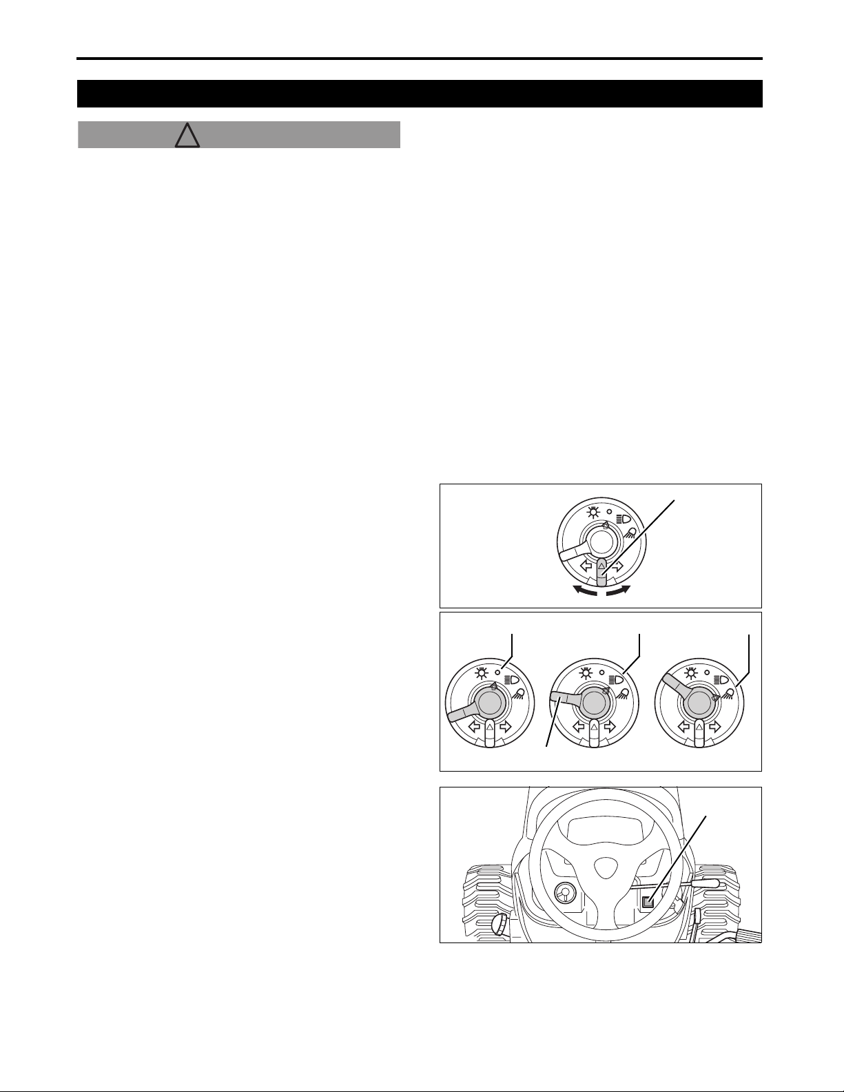
8. OPERATE THE TRACTOR
2. Operate the Tractor
! WARNING
Avoid injury:
●Before starting or operating the tractor, always check the area around the tractor for obstacles and any person nearby. Turn off the Power Take Off (PTO) switch and raise the implement.
IMPORTANT: Avoid damage.
●To prevent damage to the transmission, stop the tractor completely before shifting the range gear lever.
1. Sit on the seat.
For the adjusting method of the seat position, see “Adjust the Operator's Seat” on page 7-2, and for the fastening method of the seat belt, see “Fasten the Retractable Seat Belt” on page 7-2.
2. Use the turn signal switch, headlight/
work light switch, hazard lights button
switch as necessary.
(A) Turn signal switch
(a) Move the turn signal switch to the left to signal a
left turn of the tractor.
(b) Move the turn signal switch to the right to signal a
right turn of the tractor.
(B) Headlight/work light switch
(c) OFF
(d) Turning the blue lever to (d) position illuminates
the headlights.
(e) Turning the blue lever to (e) position illuminates
the headlights and work lights at the same time.
(C) Hazard lights button switch
A3014902
A3014901
(A)
(a) (b)
(c) (d) (e)
(B)
(C)
3. Start the engine.
Start the engine by referring to “Chapter 7.
OPERATE THE ENGINE”.
8-3
A3014901f
Sc2400 Operator’s Manual
Page 54
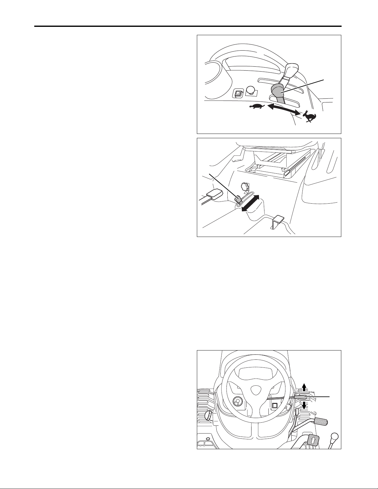
8. OPERATE THE TRACTOR
4. Use the range gear lever and the 4-
wheel drive lever to select the travel
speed.
(A) Range gear lever
(a) SLOW : Used for heavy-load operation.
Low traveling speed.
(b) FAST : Used for light-load operation.
High traveling speed.
(B) 4-wheel drive lever
(c) 4-wheel drive mode
(d) 2-wheel drive mode
IMPORTANT: Avoid damage.
●ALWAYS keep the 4-wheel drive lever in the 2wheel drive mode when traveling on a paved
surface.
●ALWAYS disengage the 4-wheel drive lever put in the 2-wheel drive mode when not needed to prevent premature wear of the front tires.
●NEVER install tire chains to the front wheels. Chains will hit and can damage the tractor.
●If disengaging the 4-wheel drive lever is difficult, stop the tractor, turn the steering wheel right and left several times. Then attempt to disengage the 4-wheel drive lever again.
●To minimize tire wear, drive in the 4-wheel drive mode only when absolutely necessary. Driving the tractor on a paved road in the 4-wheel drive mode can accelerate wear of the tires.
●To obtain better traction, keep the front tires at the maximum allowable pressure.
●When the 4-wheel drive lever is in the 4-wheel drive mode, braking will apply to all four wheels.
3014919a
(B)
3014904b
(A)
(a)
(b)
(d)
(c)
5. Adjust the throttle control lever to
attain an intended speed.
(A) Throttle control lever
(a) To increase the engine speed:
pull the throttle control lever backward.
(b) To decrease the engine speed:
push the throttle control lever forward.
Sc2400 Operator’s Manual
(b)
(A)
(a)
3014903e
8-4
Page 55

8. OPERATE THE TRACTOR
6. Raise the implement.
1. Pull the 3-point hitch control/cutting height
adjustment lever rearward and raise the mid- or
rear mounted implement to the raised position.
(A) 3-point hitch control/cutting height
adjustment lever
(a) Raised position
2. If the tractor has any implements (ex. front loader)
that use the implement control valve, pull up the
implement lock lever to release locking and use
the implement control lever to raise the
implement.
■ Function of Implement Lock Lever
! WARNING
To prevent injury from crushing:
●Never attempt to use the implement lock lever
in order to perform maintenance or repair. This
lock is for preventing the implement from being
accidentally engaged during transport or when
not being used. It will not prevent implement
leak down.
(A)
(a)
3014918d
(A)
(a)
(B)
When fixing or adjusting the implement control lever
to its NEUTRAL position, use the implement lock
lever to lock the implement control lever in place.
(A) Implement control lever
(B) Implement lock lever
IMPORTANT: Avoid damage.
●Do not attempt to operate the implement control
lever when the implement control lever has been
locked.
●When the implement control lever has been locked with the implement lock lever, move the implement control lever with light force to ensure that it has been securely locked.
(a) Raising the implement
(b) To unlock the implement control lever: Pull up the
implement control lock lever.
(c) To lock the implement control lever: Push down
the implement lock lever when the implement
control lever is in its NEUTRAL position.
3014903n
(b)
(c)
8-5
Sc2400 Operator’s Manual
Page 56

8. OPERATE THE TRACTOR
7. Disengage the parking brake.
1. Fully depress the brake pedal.
2. Fully push the parking brake lever forward to
unlock the parking brake.
3. Remove foot from the brake pedal. Make sure
that the brake pedal is unlocked.
(A) Brake pedal
(B) Parking brake lever
8. Remove foot from the brake pedal.
9. Slowly depress the forward side of
the forward and reverse drive pedal or
reverse side of the forward and
reverse drive pedal.
3014916f
(A)
(B)
(A) Forward side of the forward and reverse drive
pedal
(B) Reverse side of the forward and reverse drive
pedal
IMPORTANT
●When the drive pedal is released, the transmission will automatically return to the NEUTRAL position.
10.Operate the steering wheel and travel
to the intended destination.
11.Use the cruise control as necessary.
The cruise control is a feature that regulates forward tractor travel to a specific speed.
NOTE
●The cruise control is operative only when the tractor is traveling forward.
! WARNING! WARNING
●Use the cruise control only when traveling in a vast open area.
●Turn OFF this feature before turning the tractor or when in areas that include many obstacles.
3014916c
(B)
(A)
Sc2400 Operator’s Manual
8-6
Page 57
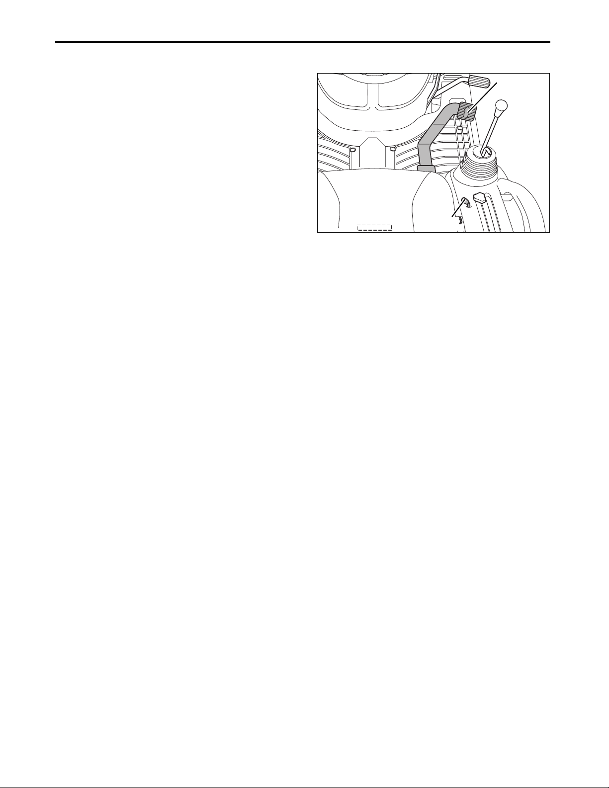
8. OPERATE THE TRACTOR
■ Engage the Cruise Control
1. Depress the forward side of the forward and
reverse drive pedal until an intended travel speed
is reached.
2. Lift up the cruise control lever to engage the
cruise control feature.
3. Remove foot from the forward side of the forward
and reverse drive pedal.
4. Remove hand from the cruise control lever.
(A) Forward side of the forward and reverse drive
pedal
(B) Cruise control lever
■ Disengage the Cruise Control
1. Depress the brake pedal.
2. Step on the forward side of the forward and
reverse drive pedal and make sure the forward
and reverse pedal is unlocked.
3014903i
(A)
(B)
NOTE
●The cruise control is disengaged when the operator depresses the brake pedal.
●If the cruise control lever is not readily disengaged, then step on the brake pedal several times.
●Also, the cruise control can be disengaged when the operator depresses the forward side of the forward and reverse drive pedal. Note, however, that the reverse side of the forward and reverse drive pedal can not be used for this purpose.
●Do not strongly step on the reverse side of the forward and reverse drive pedal when the cruise control is in the locked state.
8-7
Sc2400 Operator’s Manual
Page 58
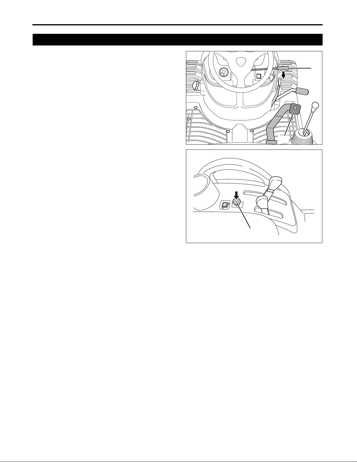
8. OPERATE THE TRACTOR
3. Stop the Tractor
1. Slowly remove foot from the forward side of the
forward and reverse drive pedal or reverse side of
the forward and reverse drive pedal.
2. Fully push the throttle control lever forward to
decrease the engine speed.
3. Step on and depress the brake pedal.
4. After the tractor has completely stopped, turn off
the Power Take Off (PTO) switch.
5. Lower the implement (if equipped) to the ground.
6. Engage the parking brake securely.
7. Run the engine at a lowest possible speed for at
least for 2 minutes.
8. Turn the key to the OFF position.
9. Remove the key from the starter key switch.
10.Make sure that the engine and other rotating
component(s) have stopped running. NEVER
leave the operator’s seat while any component is
running.
3013703a
(B)
(A)
(A) Forward and reverse drive pedal
(B) Throttle control lever
(C) Power Take Off (PTO) switch
■ Stop in an Emergency
1. Remove foot from the forward side of the forward
and reverse drive pedal or reverse side of the
forward and reverse drive pedal.
2. Depress the brake pedal.
3. Turn the key to the OFF position.
4. Keep the brake pedal pressed until all the moving
parts on the tractor come to a full stop.
5. Engage the parking brake securely.
(C)
3014919b
Sc2400 Operator’s Manual
8-8
Page 59

8. OPERATE THE TRACTOR
4. Verify During Driving
■If any of the following occurs, shut off the
engine immediately.
●Suddenly the engine slows down or accelerates on
its own.
●Any unusual noise is heard.
●Dark exhaust is suddenly emitted.
(B)
Regularly check the following during driving to
ensure that all parts are functioning normally.
(A) Fuel gauge
(B) Engine coolant warning light
If any warning light turns on during operation, immediately shut off the engine and detect the cause according to the procedure given below. Never attempt to move or start the tractor while any warning light remains “ON”.
Engine oil pressure warning light (C)
This warning light will turn on if the engine's
oil pressure drops below a predetermined
level.
If this occurs during operation of the tractor
and the light remains lit even when the
engine is accelerated to over 1100 min
(rpm) (without load), check the level of
engine oil.
(See “Check the Engine Oil Level” on page
14-7.)
-1
(C)
3014905
(D)
(A)
Alternator/battery charging light (D)
This warning light will turn on if the alternator
is not charging the battery properly.
If this occurs during operation of the tractor,
check the electrical charging system or
contact your local Cub Cadet Yanmar
dealer.
NOTE
●Contact your local Cub Cadet Yanmar dealer for technical assistance on checking and servicing of the tractor.
8-9
Sc2400 Operator’s Manual
Page 60
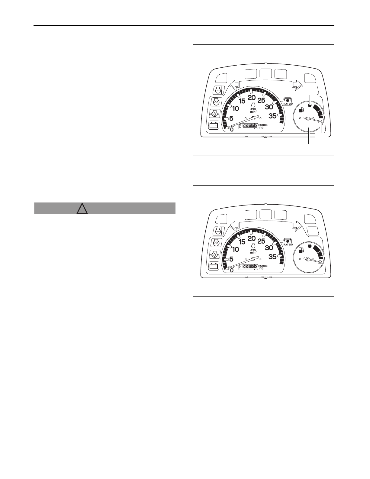
8. OPERATE THE TRACTOR
■ Fuel Gauge
Once the starter key is turned to the ON position, the
needle on this gauge will first jump to “empty” (in
order to indicate that the gauge is operating properly)
and move to a position that indicates the actual fuel
level.
IMPORTANT
●Never allow the fuel tank to become completely
empty or air may enter the fuel system and
necessitate bleeding of the whole fuel system.
(See “Refill the Fuel Tank” on page 14-3.)
(A) Fuel gauge
(a) Empty
(b) Full
■ Engine Coolant Warning Light
This warning light will turn on if the temperature of
the engine's coolant exceeds a predetermined level.
! WARNING
To avoid personal injury:
●Always allow the temperature of the coolant to drop sufficiently before attempting to remove the radiator cap.
●Always loosen the cap slightly first in order to release the internal pressure before attempting to remove the radiator cap completely.
3014905
(b)
(a)
(A)
(A)
IMPORTANT
●If the engine coolant warning light does turn on,
reduce the load on the tractor immediately, run the
engine at an idle until the light turns off, and shut
off the engine. Wait until the engine has cooled off
completely, and check to see that there is:
(1) Sufficient coolant in the radiator and reserve tank
(2) No clogging of the radiator fins and screen
(3) Sufficient tension in the fan belt
See “14. PERIODIC SERVICE” for more
information on maintenance procedures.
●If the coolant warning light turns on again even after being sure of the checkpoints above, shut off the engine immediately and contact your local Cub Cadet Yanmar dealer.
(A) Engine coolant warning light
3014905
Sc2400 Operator’s Manual
8-10
Page 61
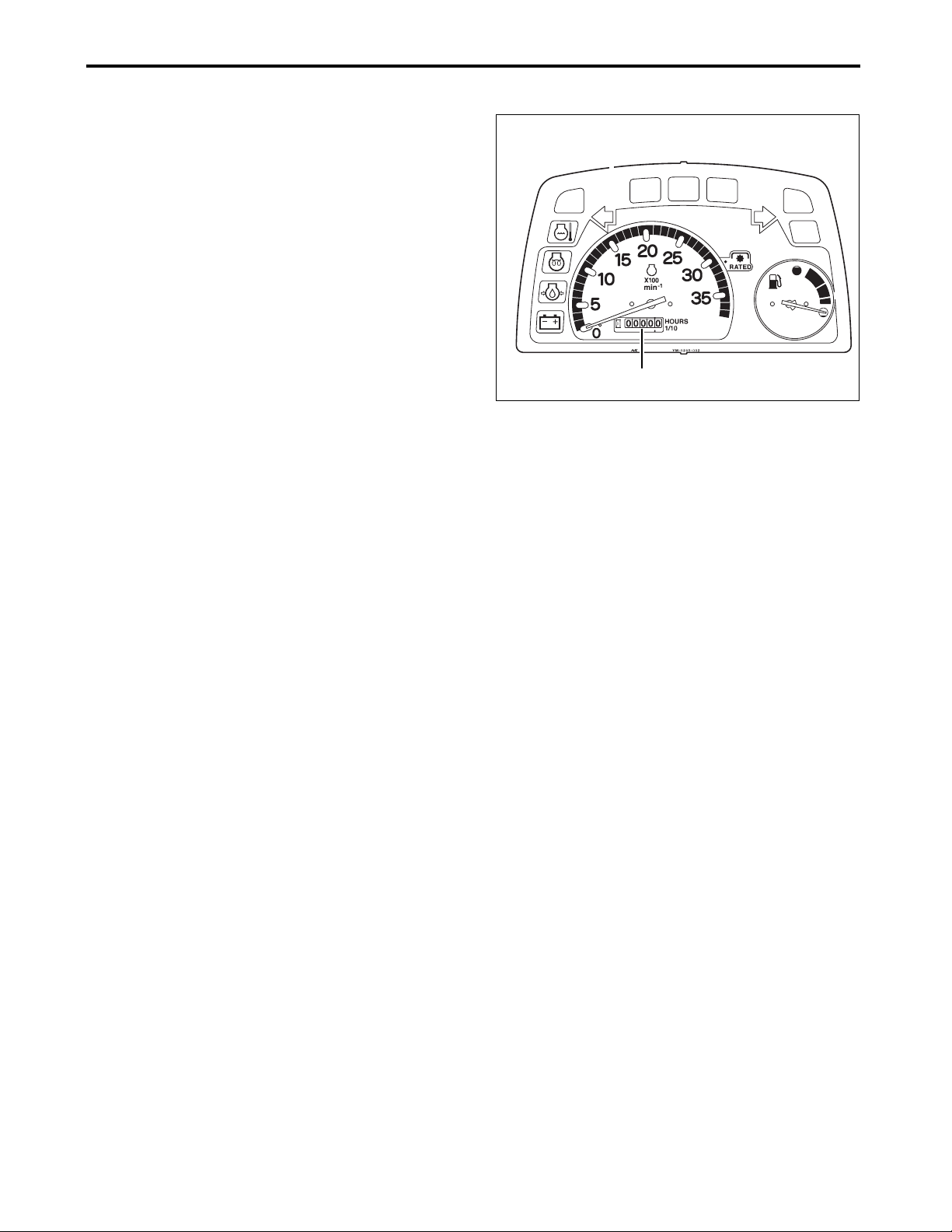
8. OPERATE THE TRACTOR
■ Hour Meter
When the key is turned to the ON position with the
engine not yet running, this 6-digit meter shows the
number of hours that the tractor has been in use. The
final digit indicates 1/10 of an hour.
(A) Hour meter
3014905
(A)
8-11
Sc2400 Operator’s Manual
Page 62

8. OPERATE THE TRACTOR
5. Park the Tractor
■ Apply the Parking Brake
! CAUTION
Avoid injury:
●ALWAYS engage the parking brake securely before leaving the tractor unattended.
1. Turn off the Power Take OFF (PTO) switch.
(A) Power Take Off (PTO) switch
2. Lower the implement to the ground, set the
implement control lever to the NEUTRAL position
and push in the implement lock lever to lock.
3. Engage the parking brake securely.
4. Turn the key to the OFF position.
5. Remove the key from the starter key switch.
6. Remove foot from the brake pedal. Make sure
that the parking brake has been fully engaged.
7. Before leaving the tractor, be fully sure that the
tractor is at a standstill.
(A) Implement control lever
(B) Implement lock lever
(C) Parking brake lever
(D) Brake pedal
IMPORTANT
●NEVER park on a steep slope. ALWAYS park on a solid, flat, level ground whenever possible. If parking on a slope is unavoidable, park the tractor across the slope, and lower the implement to the ground.
3014919b
3014903j
(A)
(C)
(D)
(A)
(B)
■ Release the Parking Brake
1. Fully depress the brake pedal.
2. Fully push the parking brake lever forward to
unlock the parking brake.
3. Remove foot from the brake pedal. Make sure
that the brake pedal is unlocked.
Sc2400 Operator’s Manual
8-12
Page 63

8. OPERATE THE TRACTOR
6. Safe Practices for Operation
1. Differential Lock
(A) Differential lock foot pedal
(a) disengage
(b) engage
! WARNING! WARNING
To prevent the tractor from overturning:
●Do not attempt to turn with the differential lock
engaged.
●Do not engage the differential lock while the
tractor is traveling at a high speed.
The differential lock is actuated to provide greater
traction when rear wheels begin to slip. Engaging the
differential lock will cause the right and left rear axles
to be locked and simultaneously rotate at a same
speed, allowing the tractor to develop maximum
traction force.
3014904c
(b)
(a)
(A)
IMPORTANT: Avoid damage.
●To prevent damage to the differential gears, NEVER engage the differential lock while the tractor is traveling at a high speed, or when only one wheel is rotating.
●The differential lock is designed to be used for short durations. Its prolonged use can damage the differential gears.
■ Engage the Differential Lock
1. Stop or slowly drive the tractor.
2. Depress the differential lock foot pedal.
■ Disengage the Differential Lock
Remove foot from the differential lock foot pedal.
IMPORTANT
●When using the differential lock, decrease the engine speed.
●To prevent transmission damage, do not use the differential lock when only one rear wheel is rotating.
• If the differential lock does not disengage when
the foot is removed from the differential lock foot
pedal, lightly step on the brake pedal several
times.
8-13
Sc2400 Operator’s Manual
Page 64

8. OPERATE THE TRACTOR
2. Drive the Tractor on Roads Safely
! CAUTION! WARNING: Avoid injury!
Exercise due caution when driving the tractor at a transport speed.
●We recommend that the user/operator use the
turn signal/hazard lights when traveling on
public roads. Before operating the tractor on a
public roadway, be aware of relevant state or
local regulations in effect. An implement safety
lighting kit is available from your local Cub
Cadet Yanmar dealer.
●If local laws permit road travel, use the flashing hazard lights and Slow Moving Vehicle (SMV) emblems when traveling on public roadways.
● When operating the tractor on a roads, strictly
observe the following precautions:
• ALWAYS ensure that right side and left side
brakes are equally adjusted.
• ALWAYS ensure that the Slow Moving Vehicle
(SMV) emblem and hazard lights are clean and
clearly visible. If a towed or rear mounted
implement jeopardizes visibility of these safety
devices, install the Slow Moving Vehicle (SMV)
emblem and hazard lights on the implement.
(A) Typical example of installed Slow Moving
Vehicle (SMV) emblem
●Turn the hazard lights and headlights ON, unless prohibited by law.
●Secure the implement being towed with lock hitch pins and safety chains.
●Drive the tractor slowly so that the tractor is under control at all times. Slow down for travel on slopes, rough roads, sharp turns or when transporting a heavy rear mounted implement.
●Disengage the 4-wheel drive to prevent excessive tire wear.
●NEVER coast downhill.
●Check whether the front wheel gearing is engaged.
●Remember that the braking characteristics differ
between the 2-wheel drive and 4-wheel drive
modes. ALWAYS be aware of the current drive
mode and use it properly.
●ALWAYS slow down before turning. High-speed turns may cause the tractor to tip over.
●ALWAYS ensure that the Slow Moving Vehicle (SMV) emblem is on the tractor and is clearly visible.
●Strictly observe all the currently effective local traffic and safety laws and regulations.
Sc2400 Operator’s Manual
(A)
P3014904
8-14
Page 65

8. OPERATE THE TRACTOR
●ALWAYS travel at a speed that allows the tractor to remain controlled and stable.
●Avoid engaging the differential lock while traveling on roads as this can cause the tractor to become uncontrollable.
●While traveling on roads, do not turn the steering wheel suddenly as this can lead the tractor to become unstable and result an extremely dangerous situation.
●While on roads, NEVER attempt to operate an
implement. During driving on road with an
implement attached to the 3-point hitch, put the 3point hitch control lever in its raised position and
lock it with the position stop knob. Do not fully close
the hydraulic flow control/stop knob in order to
keep any implements in their raised position while
the tractor is traveling.
Closing the knob could cause damage to the
hydraulic lift circuit.
●When driving the tractor on roads, NEVER exceed 10 mph (16 km/h).
3. Move the Tractor Manually while the Engine is Stopped
! WARNING! WARNING
Setting the Hydro Static Transmission (HST)
pressure release lever to the ON position makes
the tractor freely move.
●Do not operate the Hydro Static Transmission
(HST) pressure release lever on a slope. Setting
the Hydro Static Transmission (HST) pressure
release lever to the ON position on the slope
makes the axles freely move, so that the tractor
will be out of control.
●Before setting the Hydro Static Transmission (HST) pressure release lever to the ON position, park the tractor in a flat place and engage the parking brake securely.
P3014906
(A)
! WARNING! WARNING
●Do not operate the Hydro Static Transmission (HST) pressure release lever while the engine is running.
IMPORTANT: Avoid damage.
●Moving the tractor in an improper way may
damage the transmission. Move the tractor by
hand only.
• Do not move the tractor with using other
machine.
• Do not tow the tractor.
8-15
1A7880-65380
Sc2400 Operator’s Manual
Page 66

8. OPERATE THE TRACTOR
■ Hydro Static Transmission (HST) Pressure Release Lever
Hydraulic pressure in the Hydro Static Transmission
(HST) brakes the axles when the engine is not
running, so that the tractor cannot be moved.
When the hydraulic pressure in the transmission is
released by pressing the Hydro Static Transmission
(HST) pressure release lever, the tractor can be
moved.
To move the tractor, observe the following
procedure:
1. Make sure that the engine is stopped.
2. Tilt the seat forward.
(A) Seat
3. Fully depress the Hydro Static Transmission
(HST) pressure release lever.
(A) Hydro Static Transmission (HST) pressure
release lever
4. Disengage the parking brake.
5. Move the tractor.
6. After moving the tractor, fully pull up the Hydro
Static Transmission (HST) pressure release lever.
7. Engage the parking brake securely.
(A)
P3014907
Sc2400 Operator’s Manual
8-16
P3014906
(A)
1A7880-65380
Page 67

8. OPERATE THE TRACTOR
4. Transport the Tractor on a Trailer
! WARNING! WARNING
Avoid injury:
●Exercise extreme care when loading or unloading the tractor to or from a trailer or truck.
●Close the fuel shut-off valve.
NOTE
●Use a heavy-duty trailer to transport the tractor.
1. Drive the tractor forward onto the trailer.
2. Lower any implement onto the trailer deck.
3. Engage the parking brake securely.
4. Turn off the engine.
5. Remove the key from the starter key switch.
6. Close the fuel shut-off valve.
7. Tie down the tractor to the trailer with heavy-duty
straps, chains or cables. Direct both front and rear
straps down and outward from the tractor.
(A)
P3014904
IMPORTANT
●The trailer must have signs and lights required by law.
●When transporting the tractor on a trailer, the Slow Moving Vehicle (SMV) emblem may have to be removed to comply with local laws. For details, please consult your local Cub Cadet Yanmar dealer.
(A) Typical example of installed Slow Moving
Vehicle (SMV) emblem
8-17
Sc2400 Operator’s Manual
Page 68

8. OPERATE THE TRACTOR
5. Operate on Slopes and Rough Terrain
! WARNING! WARNING
Be extremely cautious when driving the tractor on a slope and rough terrain.
●To increase traction power and provide 4-wheel
braking, engage the 4-wheel drive before
driving the tractor on a slope and rough terrain.
Remember that, although 4-wheel drive greatly
assists in approach to a steep slope, there is
greater possibility of the tractor tipping over.
●To improve braking power on sloped, frozen, wet or graveled surfaces, engage the 4-wheel drive. Add weight to the tractor as necessary and travel at a lower speed to prevent skidding and loss of steering control.
●While driving the tractor, do not attempt to climb a slope that is steeper than 11 degrees.
●Even on a slope that is less than 11 degrees, do not turn or change the traveling direction, or park perpendicular to the slope.
●Before approaching a slope, select an appropriate speed setting (be sure to travel at a lower speed when on a slope). NEVER shift gears while on a slope as this can cause the tractor to become uncontrollable and suddenly roll downhill.
●Suddenly starting the tractor on an uphill slope can cause the front wheels to lift off the ground and result an extremely dangerous situation. To avoid this problem, run the engine at a lower speed and slowly start the tractor in motion.
● NEVER park the tractor on a slope. If parking on
a slope is unavoidable, chock the tires and set
the parking brake securely.
●On a slope, the tractor is unstable and more prone to tipping over, possibly leading to severe injury or even death. Remain very cautious when your tractor is on any slope.
●To prevent the tractor from tipping over, travel backward on steep slopes. If traveling backward on the slope is difficult, do not attempt to continue. Avoid extremely steep slopes.
●When exiting a ditch or deep mud, or when traveling on a steep slope, the risk of the tractor tipping over is high. Special caution is especially required in 4-wheel drive mode.
●Slowly move on any slope. NEVER change speed or direction quickly.
●When backing up a slope, keep the tractor parallel with the gradient of the slope.
3013748
Sc2400 Operator’s Manual
8-18
Page 69

8. OPERATE THE TRACTOR
1. Before approaching a slope, set the range gear
lever to the slow position.
(A) Range gear lever
(a) Slow position
2. Lightly depress the forward side of the forward
and reverse drive pedal to start moving.
IMPORTANT
●Always slowly drive the tractor on a slope.
3. ALWAYS travel slowly on a slope.
4. Drive the tractor according to the type of a slope,
as instructed below:
(A)
(a)
3014919a
■ Uphill/Downhill
Make sure that the range gear lever is in the slow
position. Run the engine at a lower speed.
■ Steep Downhill
To be able to apply the engine brake, turn the range gear lever to the slow position.
(A) Forward and reverse drive pedal
3014916b
(A)
8-19
Sc2400 Operator’s Manual
Page 70

8. OPERATE THE TRACTOR
6. About the Power Steering
! WARNING! WARNING
●NEVER operate the steering wheel suddenly, especially while traveling on a paved road. Otherwise, an accident can occur.
The power steering feature is operative only when the engine is running. Note that when the engine is running at a lower speed, the steering wheel will need slightly greater force. This is considered normal operation.
IMPORTANT
●Fully turning the steering wheel will cause the relief valve to trip and an audible signal will sound. This situation may be ignored only for a short duration. NEVER operate the steering in relief for a prolonged period.
●Turning the steering wheel while the tractor is not running can promote damage on the tires and rims. Avoid such an action whenever possible.
7. Accessory
■ 12V DC Outlet
This can be used when the key switch is in "ON"
position.
It can be used as a power source for electrical
goods.
(A) 12V DC outlet
IMPORTANT: Avoid damage.
●Do not connect a light or load of more than 120 watts.
●Do not use as a cigarette lighter.
●Do not use when wet.
●Long-term usage of the 12V DC outlet with the
engine stopped causes the battery to run out.
3014903o
(A)
Sc2400 Operator’s Manual
8-20
Page 71
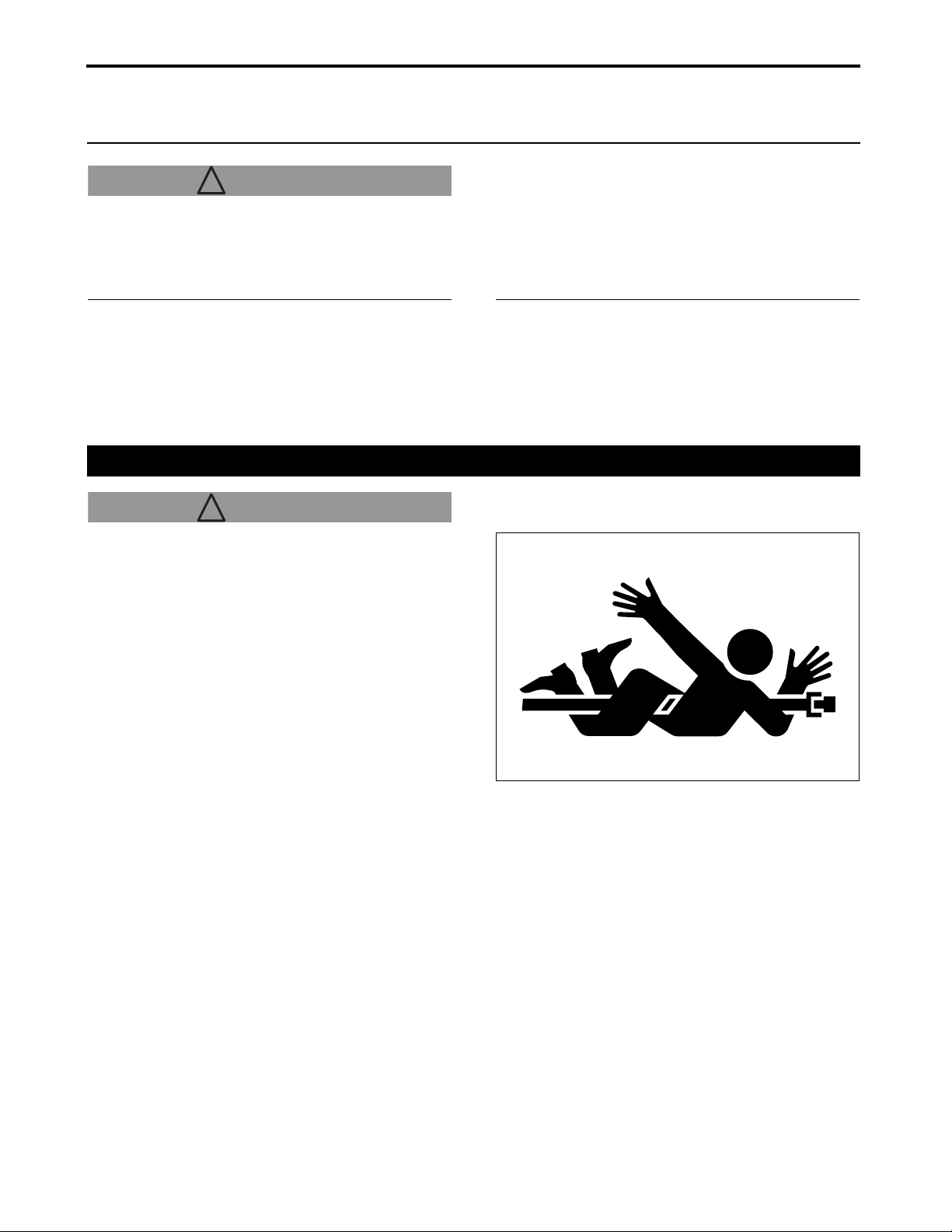
9. POWER TAKE OFF (PTO)
9. POWER TAKE OFF (PTO)
! WARNING
! WARNING
ALWAYS ensure all moving components have
stopped rotating before connecting, disconnecting,
adjusting, cleaning or servicing any Power Take Off
(PTO)-driven implement.
ALWAYS follow the Power Take Off (PTO)-driven
implement operation manuals and safety decals and
instructions before installing or operating any Power
Take Off (PTO)-driven implements.
ALWAYS ensure the Power Take Off (PTO) shaft
cover is installed. ALWAYS wait until the shaft has
completely stopped moving before attempting to
replace the Power Take Off (PTO) shaft cap.
1. Operate the Power Take Off (PTO)
! WARNING! WARNING
● Before connecting, disconnecting, adjusting
or cleaning any Power Take Off (PTO)-driven
implement, be sure to disengage the Power
Take Off (PTO), shut down the engine, and
make sure that all the components have
stopped their rotation.
● Do not approach rotating drivelines.
● Entanglement with a rotating driveline can lead
to serious injury or even death.
● Keep hands, feet and clothing away from the
rotating driveline.
● Make sure that all shields and guards are in
position and are correctly used.
● Do not run the engine at 3520 min
more while the Power Take Off (PTO) is
engaged.
-1
(rpm) or
ALWAYS set the parking brake securely and put
wheel chocks in front and behind the rear wheels.
NEVER approach or touch any rotating component.
9-1
Sc2400 Operator’s Manual
Page 72

■ Rear Power Take Off (PTO)
(A) Rear Power Take Off (PTO) shaft
9. POWER TAKE OFF (PTO)
■ Mid-Power Take Off (PTO)
(A) Mid-Power Take Off (PTO) shaft
■ Engage the Power Take Off (PTO)
NOTE
●This tractor cannot drive the Power Take Off (PTO)
unless the operator sits on the seat. When the
operator leaves the seat while the Power Take Off
(PTO) is engaged, the safety interlock system
stops the implement and the engine.
●Normally, reversing the tractor stops the MidPower Take Off (PTO) and the Rear Power Take
Off (PTO). To drive the Power Take Off (PTO)
while reversing the tractor, use the reverseoverride-switch.
(A) Reverse-override-switch
P3014908
3014919d
3014919d
(A)
(A)
(A)
Sc2400 Operator’s Manual
9-2
Page 73
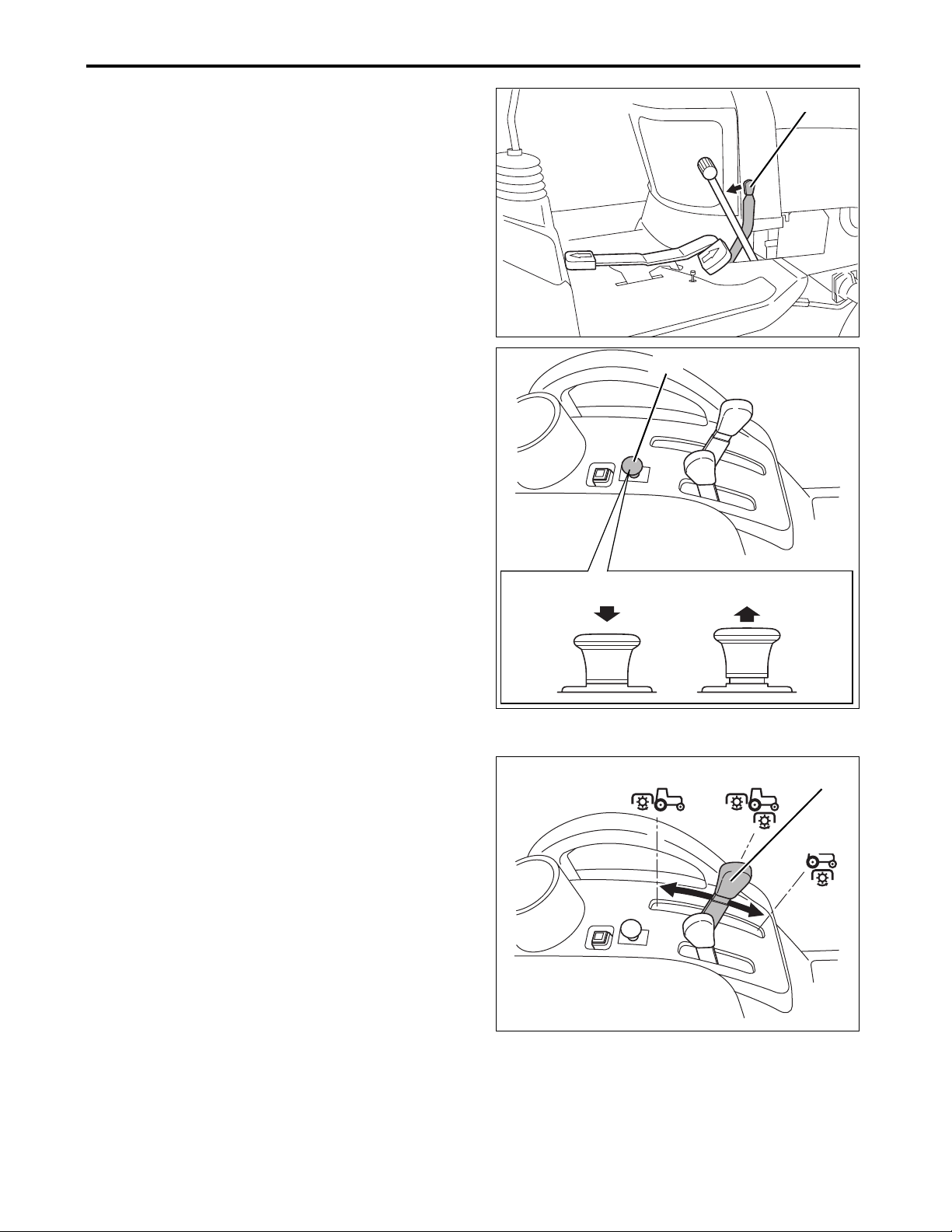
9. POWER TAKE OFF (PTO)
1. Sit on the operator's seat.
2. Engage the parking brake securely.
(A) Parking brake lever
3. Push in the Power Take Off (PTO) switch to set it
to the OFF position.
(A) Power Take Off (PTO) switch
(a) OFF position
(b) ON position
4. Start the engine.
-1
5. Adjust the engine speed to 1500 min
(rpm) or
lower.
(A)
3014916d
(A)
IMPORTANT
●In order to reduce any shock at the time of driving
the Power Take Off (PTO), make sure to reduce
the engine speed before turning ON the Power
Take Off (PTO) switch.
6. According to an implement to be used, operate
the Mid-/Rear Power Take Off (PTO) select lever.
(A) Mid-/Rear Power Take Off (PTO) select lever
(a) Operating the Mid-Power Take Off (PTO) alone
(b) Operating the Mid-Power Take Off (PTO) and the
Rear Power Take Off (PTO) at the same time
(c) Operating the Rear Power Take Off (PTO) alone
3014919g
3014926
(a) (b)
(c)
(b)
(A)
(a)
7. Pull up the Power Take Off (PTO) switch to set it
to the ON position.
9-3
3014919e
Sc2400 Operator’s Manual
Page 74
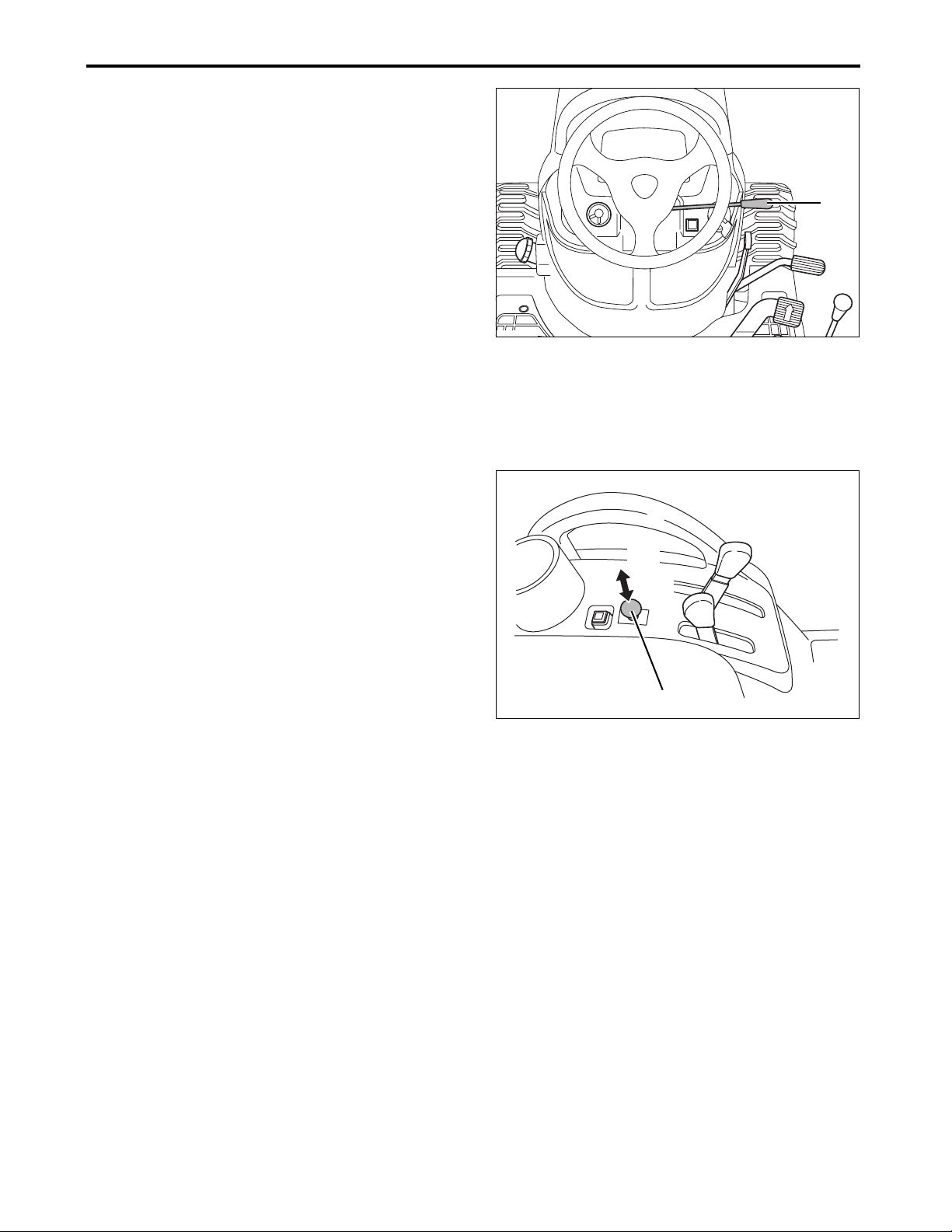
9. POWER TAKE OFF (PTO)
8. While watching the instrument panel, adjust the
engine speed suitable for operating with the
throttle control lever.
(A) Throttle control lever
NOTE
●When the engine speed is 3300 min
-1
(rpm), the
Mid-Power Take Off (PTO) rotates at
approximately 2100 min
●When the engine speed is 3100 min
-1
(rpm).
-1
(rpm), the
Rear Power Take Off (PTO) rotates at
approximately 540 min
-1
(rpm).
■ Disengage the Power Take Off (PTO)
1. Run the engine at a low speed.
2. Push in the Power Take Off (PTO) switch to set it
to the OFF position.
(A) Power Take Off (PTO) switch
(a) ON position
(b) OFF position
(A)
3014903e
(a)
(b)
3014919c
(A)
Sc2400 Operator’s Manual
9-4
Page 75

9. POWER TAKE OFF (PTO)
2. Install an Implement to the Power Take Off (PTO) Drivelines
IMPORTANT: Avoid damage.
●Observe the driveline manufacturer's installation instructions for driveline mounting angle and the length of overlaps on the two-part driveline shafts. An incorrectly installed implement can promote wear of the driveline and/or damage the tractor.
3. Operate the Power Take Off (PTO) while the Tractor is Traveling in the Reverse Direction (Reverse Override Function)
! WARNING! WARNING
●Use EXTREME caution to check that anyone or any object is not present in the rear area when using the Power Take Off (PTO) in reverse.
Normally, reversing the tractor stops the Mid-Power Take Off (PTO) and the Rear Power Take Off (PTO). To drive the Power Take Off (PTO) while reversing the tractor, observe the following instructions:
1. Press the reverse-override-switch to enable the
reverse override function.
2. The switch illuminates and the Mid-Power Take
Off (PTO) and the Rear Power Take Off (PTO)
can be driven during reverse movement.
(A) Reverse-override-switch
! CAUTION
●Once the reverse-override-switch is activated,
the reverse override function cannot be
disabled unless the engine is stopped.
(A)
3014919f
9-5
Sc2400 Operator’s Manual
Page 76

10. 3-POINT HITCH
10. 3-POINT HITCH
! WARNING
! WARNING
ALWAYS install an appropriate counterbalance to
the front of the tractor, if necessary, when using a 3point hitch-mounted implement.
During transportation, put the 3-point hitch control/
cutting height adjustment lever in its raised position
and lock it with the position stop knob. Do not fully
close the hydraulic flow control/stop knob.
ALWAYS use implements designed for a 3-point
hitch. NEVER use unapproved implements with the
3-point hitch. Contact your local Cub Cadet Yanmar
dealer for technical assistance.
1. 3-Point Hitch
! WARNING
Avoid injury:
●Make sure to stop the engine and then remove the key. Make sure that the engine has been stopped completely.
●Make sure that no other parts are moving. If any part or component is still moving, wait until it comes to complete stop.
●Installation/removal of an implement must be
performed in a flat and solid place.
●After the implement and the 3-point hitch have
been installed, check for possible interference
with the Power Take Off (PTO) shaft and other
machine components. If interference is found,
correct it.
(A) Rear Power Take Off (PTO) shaft
(B) Left lift link
(C) Left lower link
(D) Sway links
(E) Right lower link
(F) Right lift link
(G) Top link retainer
(H) Top link
(A)
(B)
(C)
(H)
(G)
(F)
Sc2400 Operator’s Manual
10-1
3014910a
(D)
(E)
Page 77
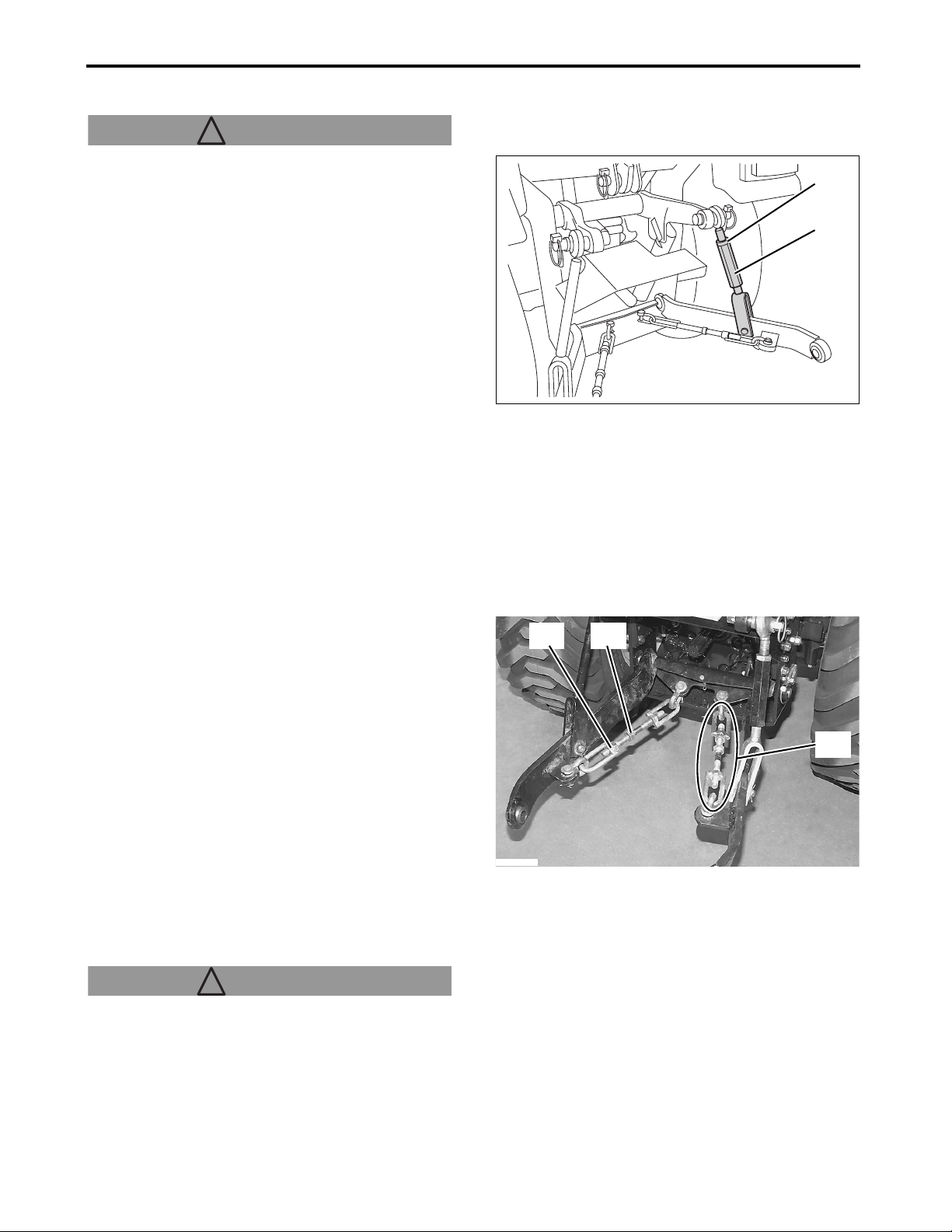
10. 3-POINT HITCH
■ Right Lift Link
! WARNING
●Chock the four wheels to secure the tractor,
before servicing the right lift link.
(A)
1. Lower the rear mounted implement.
2. Safely stop the machine.
3. Loosen the locknut.
4. Turn the turnbuckle to adjust the right lift link
length until the implement mounted to the 3-point
hitch is level.
5. Retighten the locknut.
(A) Locknut
(B) Turnbuckle
■ Top Link
For adjusting the posture of the implement, use the
top link. The posture can be adjusted by turning the
turnbuckle to elongate or contract the link.
Installation position and length of the top link depend
on the implement. Adjust them according to the
instruction manual of the implement.
■ Sway Link
Adjust lateral sway of the implement by turning the
turnbuckle of the sway links to elongate or contract
the sway links.
(B)
3014921
(A) (B)
1. Lower the rear mounted implement.
2. Safely stop the machine.
3. Loosen the locknut.
4. Adjust the sway link length by turning the
turnbuckle, so that the implement has correctly
lateral sway.
5. After adjusting the lateral sway of the implement,
tighten the locknut.
(A) Locknut
(B) Turnbuckle
(C) Sway link
■ Hitch
! WARNING! WARNING
●Do not tow anything by the use of the top link or rear axle. Otherwise, the tractor can tip over to cause serious injury or death.
●The hitch hole should only be used for towing light loads. (Maximum towing load: 552 lb. (250 kg))
●For maximum allowable weight to be towed, see "Chapter 4. IMPLEMENT CAPACITIES".
10-2
(C)
P3014908
Sc2400 Operator’s Manual
Page 78
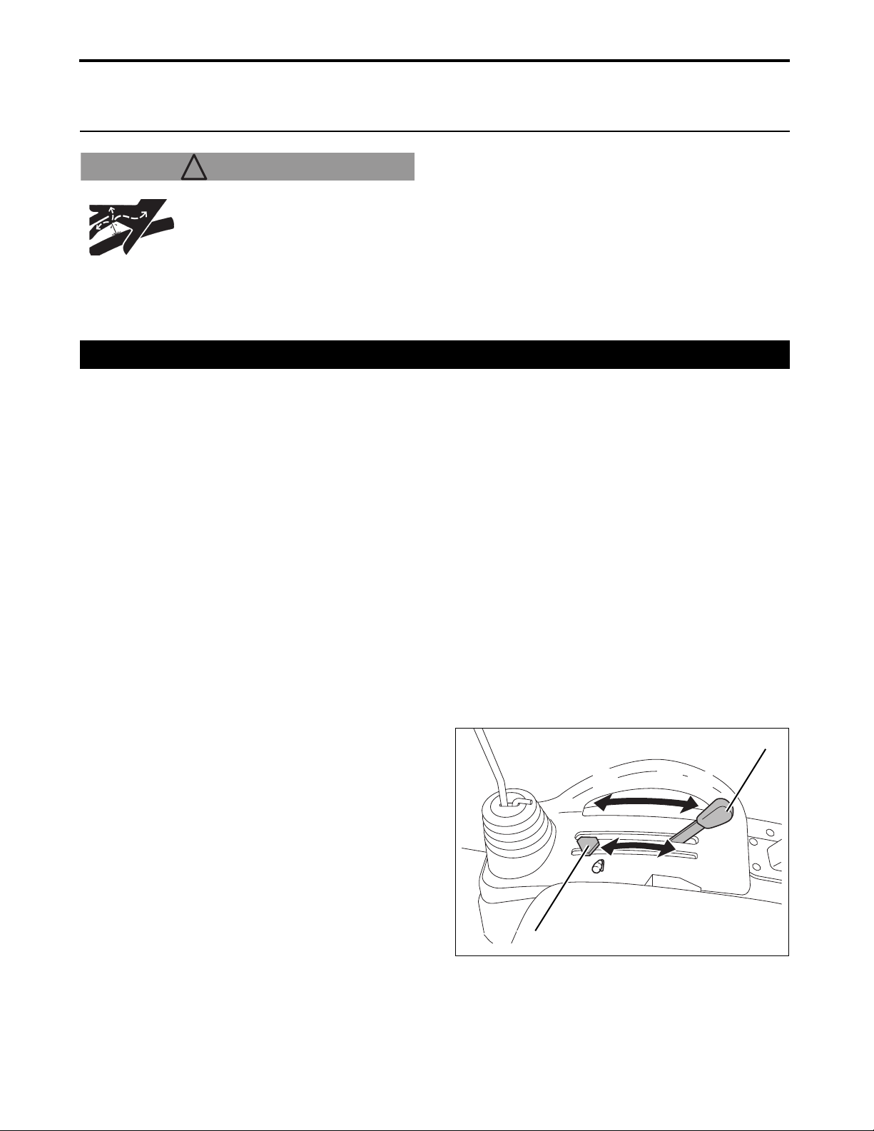
11. HYDRAULIC SYSTEM
11. HYDRAULIC SYSTEM
! WARNING! WARNING
ALWAYS fully release the internal
hydraulic pressure before
disconnecting a hydraulic line.
ALWAYS ensure that all
connections are tight and all the
hydraulic lines, pipes and hoses are free from wear
or damage.
1. 3-Point Hitch Control System
IMPORTANT
●NEVER operate the 3-point hitch control/cutting
height adjustment lever before the engine has
been sufficiently warmed up.
●If the 3-point hitch control/cutting height adjustment
lever is operated before the engine has been
warmed up, the hydraulic system can be damaged
or develop a failure.
●If abnormal hydraulic noise occurs after the 3-point
hitch has been raised, then misadjustment or failure
of the hydraulic system should be suspected.
In such a case, immediately stop operation and
contact your local Cub Cadet Yanmar dealer to
service or repair the tractor.
■ Operate the 3-Point Hitch Control/Cutting Height Adjustment Lever to Raise or Lower
the 3-Point Hitch
Use the 3-point hitch control/cutting height
adjustment lever, when raising or lowering the midor rear mounted implement.
1. Shift the 3-point hitch control/cutting height
adjustment lever to the intended position.
2. Adjust the position stop knob to set the lowest
position of the implement to the desired height.
(A) 3-point hitch control/cutting height
adjustment lever
(B) Position stop knob
(a) Moving the 3-point hitch control/cutting height
adjustment lever forward will lower the
implement.
(b) Moving the 3-point hitch control/cutting height
adjustment lever backward will raise the
implement to raise higher.
Sc2400 Operator’s Manual
11-1
3014918c
(B)
(a)
(b)
(A)
Page 79
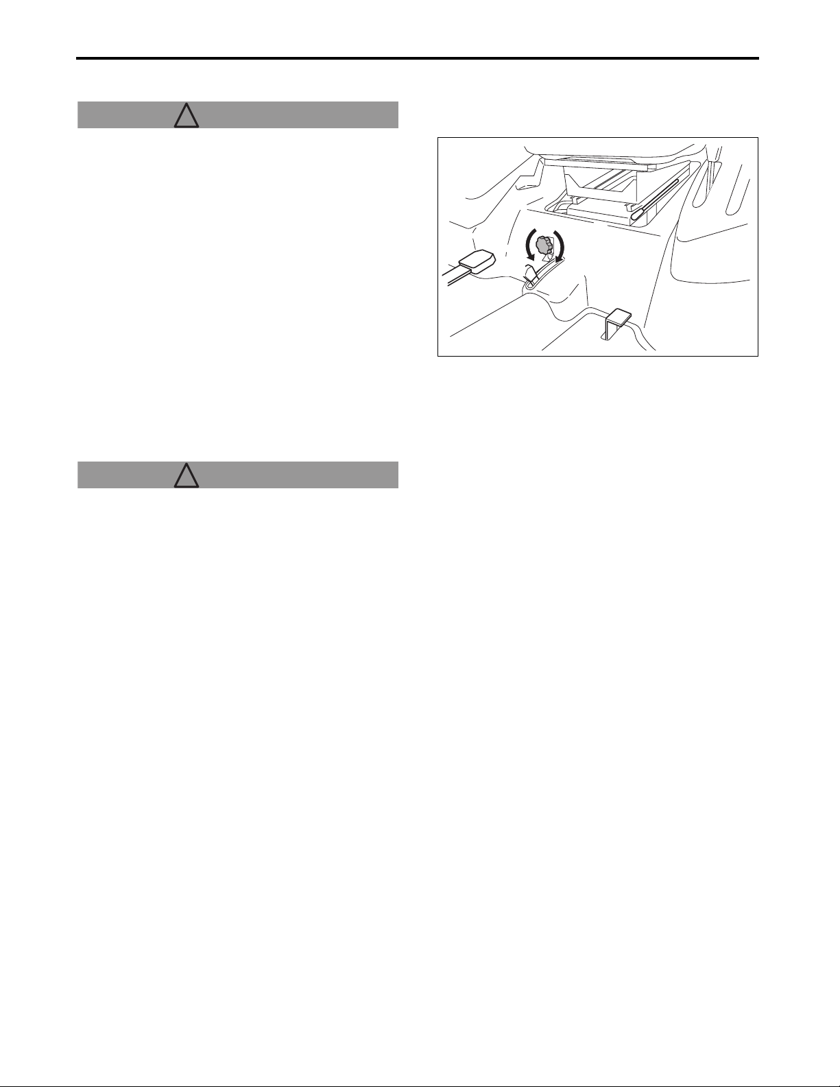
11. HYDRAULIC SYSTEM
■ Hydraulic Flow Control/Stop Knob
! WARNING! WARNING
●Lowering the 3-point hitch too fast can lead to
accident or failure.
●Adjust the hydraulic flow control/stop knob so
that the time for lowering the implement from
the highest position to the lowest position
becomes 2 seconds or longer.
The lowering speed of the lower link is governed by
the position of the hydraulic flow control/stop knob.
Also, this knob is used to stop the lower link at an
intended position.
(a) Turning the knob clockwise will cause the
lowering speed to decrease.
Tighten the knob by fully turning clockwise to stop
the lower link.
(b) Turning the knob counterclockwise will cause the
lowering speed to increase.
! WARNING! WARNING
●NEVER use the hydraulic flow control/stop
knob for holding an implement in the raised
position for maintenance. Loss of hydraulic
pressure may cause the implement to drop
suddenly. Lower the implement onto solid
blocks or remove before starting any
maintenance.
IMPORTANT
●For prolonged loader work with a weight attached
to the lower link, raise the lower link to any position
and fully tighten the hydraulic flow control/stop
knob.
3014904d
(b)
(a)
11-2
Sc2400 Operator’s Manual
Page 80
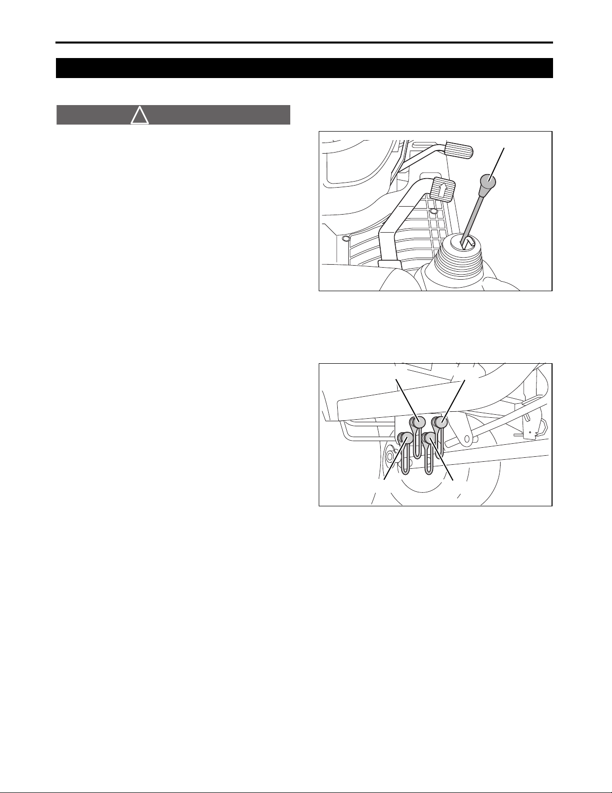
11. HYDRAULIC SYSTEM
2. Control the Implement Control Valve (Option)
■ Implement Control Valve (Option)
! WARNING! DANGER
Avoid injury:
●Escaping high pressure oil can penetrate the
skin and cause severe injury. Avoid this hazard
by relieving pressure prior to connection of
hydraulic or other high pressure lines.
Retighten all the connections before applying
pressure.
●Use a piece of cardboard to detect leaks.
Protect hands and body against high pressure
fluids.
●If an accident should occur, immediately seek
medical attention. Any high pressure fluid
injected into the skin must be surgically
removed within a few hours; otherwise,
gangrene may occur.
3014903k
(A)
(A) Implement control lever
These couplers are used in pairs of 1 and 2, and 3
and 4. If, after the couplers and hydraulic lines have
been connected, the connected implement moves in
a direction opposite to an expected direction, then
connect the coupler 1 to the hydraulic line that was
previously connected to the coupler 2, and connect
the coupler 2 to the hydraulic line that was previously
connected to the coupler 1. Repeat this procedure
for the couplers 3 and 4.
(1)-(4) Hydraulic quick coupler
IMPORTANT
●NEVER connect the coupler 1 to the coupler 3, or
the coupler 2 to the coupler 4. Contact your local
Cub Cadet Yanmar dealer for technical assistance.
3014906
(2)
(1)
(3)
(4)
Sc2400 Operator’s Manual
11-3
Page 81

11. HYDRAULIC SYSTEM
■ Implement Control Lever (Option)
The implement control valve has a “float” position.
When the implement control valve is in this position,
implements such as blades or loaders, lowered to the
operating position, are allowed to follow ground
contours.
Push the implement control lever forward beyond the
valve detent position to the “float” position.
(a) Lower
(b) “Float”
(c) Dump
(d) Dump faster
(e) Raise the implement
(f) Roll back
IMPORTANT: Avoid damage.
●Prevent damage or contamination to the female
quick couplers. ALWAYS leave the color-coded
hose ends connected to the couplers when the
couplers are not in use.
(f)
(b)
(a)
(c)
(d)
(e)
NOTE
●When the implement control lever is released, it
returns to its neutral position.
■ Implement Lock Lever (Option)
When fixing the implement control lever at its neutral
position, use the implement lock lever.
(A) Implement control lever
(B) Implement lock lever
IMPORTANT: Avoid damage.
●Do not attempt to operate the implement control
lever when the implement control lever has been
locked.
●When the implement control lever has been locked
with the implement lock lever, move the implement
control lever with light force to ensure that it has
been securely locked.
(a) For unlocking the implement control lever:
Pull up the implement lock lever.
(b) For locking the implement control lever:
Push down the implement lock lever when the
implement control lever is in its neutral position.
3014903n
1A7880-65410
(a)
(A)
(B)
(b)
11-4
Sc2400 Operator’s Manual
Page 82
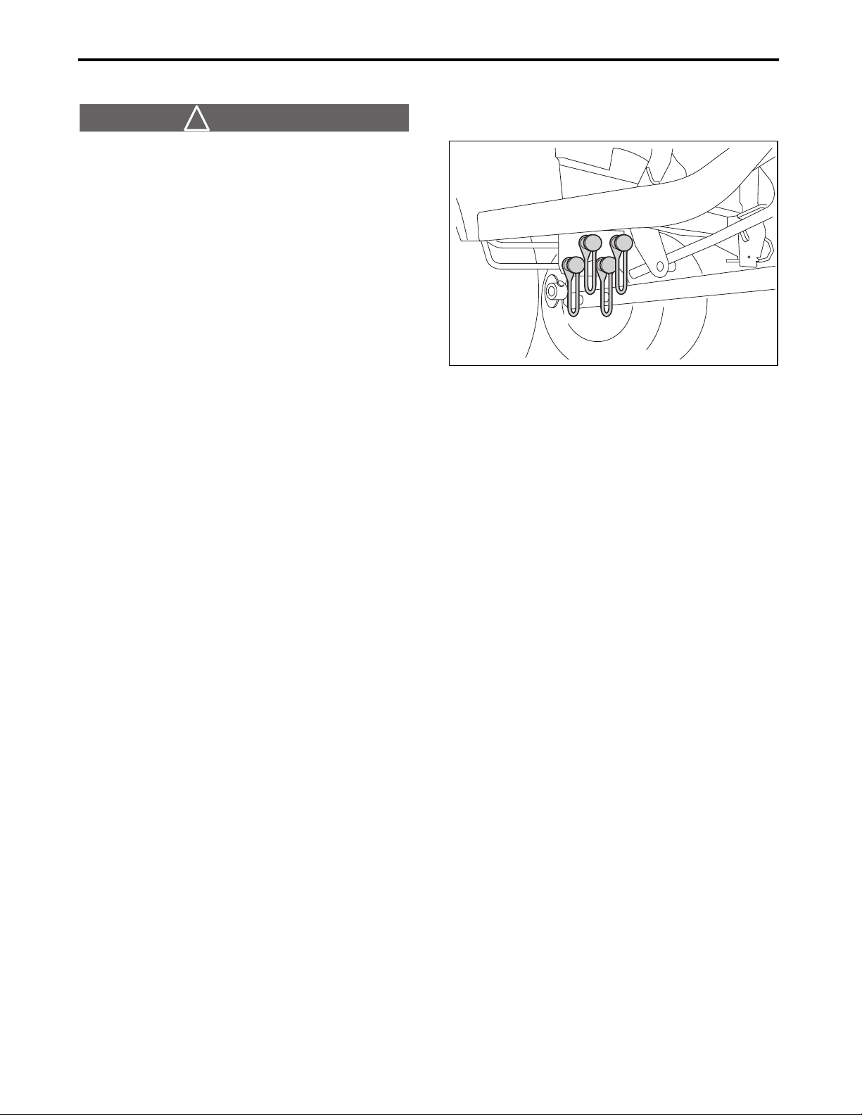
11. HYDRAULIC SYSTEM
■ Connect the Implement Hydraulic Hoses
! WARNING! DANGER
●Before all the hydraulic system pressure has
been fully relieved, do not attempt to connect
the hoses to the tractor implement control valve
couplers.
1. Park the tractor safely and securely.
2. Fully relieve hydraulic pressure be moving the
implement control lever forward and backward and
right and left several times.
3. For the correct procedure to connect the hydraulic
hoses to the couplers, see the implement
instruction manual.
3014906
Sc2400 Operator’s Manual
11-5
Page 83

12. TIRES, WHEELS AND BALLAST
12.
TIRES, WHEELS AND BALLAST
! WARNING! WARNING
Mounting the tire is dangerous work. Qualified professional personnel should mount the tire on the rim using proper equipment.
ALWAYS keep the tires inflated to the correct
pressure. NEVER exceed the recommended inflation
pressure specified in this Operator’s Manual.
1. Tires
! WARNING! WARNING
Avoid injury:
●Mounting the tire is dangerous work. Qualified
professional personnel should mount the tire
on the rim using proper equipment.
When servicing or replacing the tire(s), ALWAYS
keep the tractor securely supported.
ALWAYS keep the wheel bolts tightening torque to
the specified torque.
IMPORTANT
●Only use the tires approved by Cub Cadet Yanmar
dealers.
●When intending to use tires whose size is different
from that of the original tires, contact your local
Cub Cadet Yanmar dealer for the information about
front drive gear ratio.
12-1
Sc2400 Operator’s Manual
Page 84

12. TIRES, WHEELS AND BALLAST
■ Tire Inflation Pressure
! WARNING! WARNING
●ALWAYS keep the tires inflated to the correct
pressure. NEVER exceed the recommended
inflation pressure specified in this Operator's
Manual.
Inflation pressure gradually reduces as time elapses.
Check the pressure of each tire before starting the
day's operation and inflate the tires as necessary to
the recommended pressures. If the tire pressures
significantly decrease though the tires are correctly
inflated every day, immediately contact your local
Cub Cadet Yanmar dealer to inspect or replace the
problem tire(s).
Before front loader work, make sure to check the tire
pressure and, if necessary, inflate the tire(s) to the
recommended pressure.
For the appropriate inflation pressure, see the
following table:
Front
Rear
Tire size Inflation pressure
(psi(kgf/cm
18 × 8.50 - 10
26 × 12.00 - 12
20 (1.4) 22 (1.5)
20 (1.4) 22 (1.5)
2
))
■ Wheel Bolt Tightening Torque
! WARNING! WARNING
●ALWAYS keep the wheel bolts tightening to the
specified torque.
●With the wheel bolts loosened, do not drive the
tractor.
Before starting day’s operation, check tightening torque of each of the tire wheel bolts and, if necessary, retighten to the specified torque. For the specified torque, see the following table:
Front wheel bolt (ft•lbs (N•m)) 52 - 59 (70 - 80)
Rear wheel bolt (ft•lbs (N•m)) 52 - 59 (70 - 80)
Inflation pressure when an implement such as the front
loader has been attached to the front of the machine
(psi(kgf/cm
2
))
Sc2400 Operator’s Manual
12-2
Page 85

12. TIRES, WHEELS AND BALLAST
2. Ballast
■ Front Ballast
To mount the front ballast, the optional front weight
hitch is required.
To improve stability and traction, add ballast
indicated in the table below. (Front End Weights)
Heavy pulling and rear mounted implements can
cause the front wheels to lift. To cope with this
situation, add ballast so that reliable steering control
is maintained and tip-over of the tractor is prevented.
Remove the ballast when no longer necessary.
NOTE
●For information about the optional front weight
hitch, contact your local Cub Cadet Yanmar dealer.
Front End Weights (Option)
The front end weights can be mounted to the optional
front weight hitch. For the appropriate number of
weights, see the table below as reference only.
For accurate number of front weight, contact your
local Cub Cadet Yanmar dealer.
Implement Name Number of Weight
42" Rotary Tiller 0
48" Box Scraper 0
60" Rear Blade 0
48" Grooming Mower 4
Post hole digger 0
3013715
(A)
(B)
NOTE
●One (1) weight = 44 lb. (20 kg)
(A) Front end weights (option)
(B) Front weight hitch (option)
! WARNING! WARNING
●NEVER overload the tires. (Maximum front axle
load (Right + left): 1570 lb. (712 kg))
●NEVER add weight in excess of the limits
indicated below.
Maximum Weight
! WARNING! WARNING
●NEVER overload the tires.
●NEVER add weight in excess of the limits
indicated below.
Maximum weight: 176 lb. (80 kg) (44 lb. × 4 pcs)
12-3
Sc2400 Operator’s Manual
Page 86

12. TIRES, WHEELS AND BALLAST
■ Rear Ballast
Using Liquid Weight for the Tires
! WARNING! WARNING
Avoid injury:
●Installation of liquid weight requires special
implement and training. An exploding tire can
lead to injury. Contact your local Cub Cadet
Yanmar dealer or a tire service store to do this
task.
●When using the front loader, always put liquid
weight in the rear wheels. Failure to add
sufficient liquid weight may result in
overturning.
IMPORTANT: Avoid damage.
●NEVER exceed the maximum load ratings
indicated on the tires.
●ALWAYS cover rim completely with the liquid to
prevent corrosion, but do not exceed 75%. A larger
amount of the liquid causes a limited air space to
be left in the tire, and which is too small to absorb
shocks, possibly leading to damaged tire.
NOTE
●We do not recommend that alcohol be used as the
ballast. Calcium chloride solution is heavier.
●A water solution of calcium chloride offers a safe
ballast, and will prevent freezing. If properly used, it
will not damage tires, tubes or rims.
●A mixture of 3.5 lb. of calcium chloride and
approximately 1 US gal of water (0.4 kg/L) will not
fully freeze at a temperature above –50°F (–45°C).
●Fill tubeless tires at least to the valve stem height
(at least 75%). Smaller amount of the solution
results in partly exposed rims, possibly leading to
corrosion of the rim.
(A) Correct: 75%-full The remaining air can be
compressed like a cushion.
(B) Incorrect: 100%-full Water cannot be
compressed.
(C) Air
(D) Water
IMPORTANT
●To avoid transmission from damage, do not use rear wheel weight and liquid ballast at the same time.
3013763
(A)
(C)
(B)
(D) (D)
Sc2400 Operator’s Manual
12-4
Page 87

13. MAINTENANCE
13. MAINTENANCE
●For the checkpoints (✔) listed below, check and service at the intervals indicated in the table.
●For the inspection and maintenance procedures, see “Chapter 14. PERIODIC SERVICE”.
1. Maintenance Check List
No Topic Time
1 Refueling the fuel tank Daily
Engine oil level Check Daily
2
Engine oil Change
3 Engine oil filter Replace
Transmission/
hydraulic oil level
4
Transmission/
hydraulic oil
Transmission/
5
hydraulic oil filter
Front axle case
oil level
6
Front axle case oil
7 Front axle pivot Adjust Daily
Fuel/water
8
separator
9 Fuel filter Replace Every 500hr
Air cleaner
10
element
11 Fan belt Adjust Every 50hr
Radiator hose
12
and clamp
Radiator cooling
13
fins/screen
Front grille
14
screen
15 Cooling system
16 Coolant Change
17 Fuel line
18 Intake air hose
Safety interlock
19
system
20 Greasing and lubricating Every 50hr
21 Brake Check Daily
Check Daily
Change
Replace
Check Every 50hr
Change Every 500hr
Check Every 50hr
Clean Every 100hr
Replace Every 500hr
Clean Every 100hr
Replace Every 1 year
Check Daily
Replace
Clean Daily
Clean Daily
Check Daily
Flush
Check Daily
Replace
Check Daily
Replace
Check Daily
50/100hr and
Every 100hr
50/200hr and
Every 200hr
50/300hr and
Every 300hr
50/300hr and
Every 300hr
Every 2 years
Every 1000hr
or a year
Every 1000hr
or a year
Every 2 years
Every 2 years
Daily
5
1550100
150
200
Service Intervals
250
300
350
Hours
400
450
500
550
600
650
700
750
800
850
900
950
After
Purchase
1000
1 year
2 years
✔
✔
✔✔✔✔✔✔✔✔✔✔✔
✔✔✔✔✔✔
✔
✔✔ ✔ ✔
✔✔ ✔ ✔
✔✔✔✔✔✔✔✔✔✔✔✔✔✔✔✔✔✔✔✔
✔✔
✔
✔✔✔✔✔✔✔✔✔✔✔✔✔✔✔✔✔✔✔✔
✔✔✔✔ ✔✔✔✔✔
✔✔
✔✔
✔✔✔✔✔✔✔✔✔✔
✔
✔✔✔✔✔✔✔✔✔✔✔✔✔✔✔✔✔✔✔✔
✔
✔
✔
✔
✔
✔✔
✔✔
✔
✔
✔
✔
✔
✔✔✔✔✔✔✔✔✔✔✔✔✔✔✔✔✔✔✔✔
✔
13-1
Sc2400 Operator’s Manual
Page 88

13. MAINTENANCE
Service Intervals
No Topic Time
Seat belt & Roll-
22
Over Protective
Structure (ROPS)
23 Wheel bolt torque Check Daily
24 Inflation pressure Check Daily
25 Toe-in Adjust Every 200hr
Engine valve
26
clearance
Fuel injection
27
nozzle injection
pressure
Fuel injection
28
pump
29 Light bulb Check Daily
30 Hydraulic hose
Check Daily
Adjust Every 1000hr
Check Every 1000hr
Check Every 1000hr
Check Daily
Replace
Every 2 years
Daily
5
1550100
150
200
250
300
✔
✔✔✔✔✔✔✔✔✔✔✔✔✔✔✔✔✔✔✔✔✔✔✔
✔
✔✔✔✔✔
✔
✔
350
Hours
400
450
500
550
600
650
700
750
800
For assistance in periodic maintenance procedures, contact your local Cub Cadet Yanmar dealer.
850
900
950
✔
✔
✔
After
Purchase
1000
1 year
2 years
✔
2. Lubricants
No. Locations Capacities Lubricants
1 Fuel
2Coolant
Engine crankcase
3
(with filter)
4 Transmission case
5 Front axle case
Approximately 5.8 US gal
(22 L)
Approximately 3.4 US qt.
(3.2 L)
Approximately 2.2 US qt.
(2.1 L)
Approximately 2.0 US gal
(7.5 L)
Approximately 2.6 US qt.
(2.5 L)
Greasing No. of greasing points Capacity Type of grease
6
Drive pedal 1 Until grease overflows
No.2-D diesel fuel
No.1-D diesel fuel if temperature is below 14°F (–10°C)
High Quality Permanent Type Antifreeze
(Ethylene Glycol with corrosion and rust
inhibitor chemicals)
Coolant Mixture Ratio
Distilled Water 50% : Antifreeze 50%
API Service Classifications CF or higher
SAE 10W-30 or SAE 10W-40
Cub Cadet Hydraulic/Transmission Fluid
Cub Cadet GEAR LUBE
or SAE 80W-90 gear oil
Cub Cadet
251H EP Grease
or
General all purpose
grease
NLGI grade No.2
(Specifications and design are subject to change without prior notice for improvement.)
Sc2400 Operator’s Manual
13-2
Page 89

13. MAINTENANCE
3. Replacement Parts
1. Technical Document
[U.S.A. and Canada]
If you want to obtain a copy of Illustrated Parts List or Technical Manual the tractor, contact your local Cub Cadet Yanmar dealer.
2. Parts
We recommend the use of the Cub Cadet Yanmar authentic parts and lubricants that are available from your local Cub Cadet Yanmar dealer.
When ordering a part, tell your local dealer the machine serial number and engine serial number for the tractor. These numbers are those previously entered in “Chapter 2. SERVICE THE TRACTOR”.
13-3
Sc2400 Operator’s Manual
Page 90
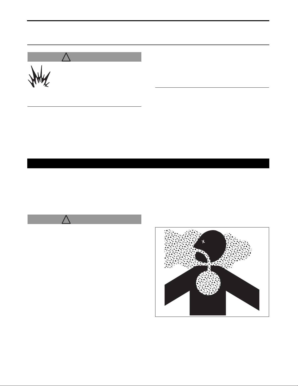
14. PERIODIC SERVICE
14. PERIODIC SERVICE
! WARNING! WARNING
NEVER smoke around the battery or
during refueling. Keep sparks or open
flames away from the battery and fuel
tank. The battery emits hydrogen and
oxygen during recharging and can pose
a serious hazard.
NEVER work under any hydraulically supported
devices. Such devices can settle, suddenly leak or
be accidentally lowered. ALWAYS support the tractor
securely with rugged stands or other appropriate
means.
ALWAYS allow the tractor to fully cool down before
accessing the engine, muffler, radiator or other hot
components.
ALWAYS park your tractor on a solid, level ground,
engage the parking brake securely, turn off the
Power Take Off (PTO) switch, lower the implement to
the ground, set the forward and reverse drive pedal
to the NEUTRAL position, stop the engine and
remove the key from the starter key switch before
starting any service work.
■ Warranty and Repair of the Engine
A maintenance, inspection, repair or replacement
service of engine emission control devices and
systems may be performed at the owner’s expense
by any qualified off-road engine repair shop or
mechanic. Warranty repairs must be executed by an
authorized Cub Cadet Yanmar dealer.
! WARNING! WARNING
Avoid personal injury:
●Engine emission gas contains carbon monoxide
that, if inhaled, can cause severe poisoning or
even death.
●NEVER run the engine in a poorly ventilated,
enclosed indoor space.
●To release the engine emission gas to an
outdoor area, connect an extension pipe to the
engine exhaust pipe.
●Allow fresh outside air to flow into the work
space to remove the engine emission gas from
that space.
NEVER inhale the emission gas.
Sc2400 Operator’s Manual
14-1
Page 91

14. PERIODIC SERVICE
1. Open/Close the Hood
! WARNING! WARNING
●Do not open the hood while the engine is running.
●Do not touch the hot muffler or exhaust pipe.
■ Open the Hood
1. Turn the hood open/close knob clockwise while
slightly pushing the upper portion of the hood.
The hood lock will be released.
(A) Hood open/close knob
(a) Close
(b) Open
(A)
(a)
(b)
3014920
2. Lift up the hood with both hands and tilt it forward.
(a) Tilt the hood forward
■ Close the Hood
1. Lift up the hood with both hands and tilt it toward
the engine side.
2. Lock the hood open/close knob by turning it
counterclockwise while slightly pushing the upper
portion of the hood.
! CAUTION
●When closing the hood, avoid pinching fingers with the hood.
(a)
P3014909
NOTICE
●Periodically clean around the hood open/close knob. Accumulation of soil or dust can cause the knob to be difficult to turn.
14-2
Sc2400 Operator’s Manual
Page 92

14. PERIODIC SERVICE
2. Daily Checks
Always complete the designated daily checkpoints
before attempting to start or operate the tractor.
Failure to complete these checkpoints could result in
personal injury or decrease the service life of the
tractor and its parts.
! WARNING
To avoid personal injury:
●Before attempting to check or service the
tractor, always make sure it is on a level surface,
the engine is shut off, the parking brake is
engaged, and full weight of the implement is on
the ground.
■ Visual Checks
Before service or operation, always check under and
around the tractor for parts that may have come loose,
build-up of grease or dirt, leakage, and broken or worn
parts.
■ Refill the Fuel Tank
IMPORTANT: Avoid damage.
●NEVER use a galvanized container to store fuel.
Diesel fuel in a galvanized container reacts with the
zinc coating in the container to generate zinc
flakes. If the fuel contains water, a zinc gel will also
occur. The zinc gel and flakes will quickly clog the
fuel filter and damage the fuel injection nozzle and
fuel pump.
Diesel Fuel Specifications
Diesel fuel should comply with the following specifications. The table lists several worldwide specifications for diesel fuels.
Diesel Fuel Specification Location
No. 2-D, No. 1-D, ASTM D975-94 USA
EN590:96 European Union
ISO 8217 DMX International
BS 2869-A1 or A2 United Kingdom
JIS K2204 Grade No.2 Japan
KSM-2610 Korea
GB252 China
Sc2400 Operator’s Manual
14-3
Page 93

14. PERIODIC SERVICE
Additional Technical Fuel Requirements
●The fuel cetane number should be equal to 45 or higher.
●The sulfur content must not exceed 0.5% by volume. Less than 0.05% is preferred.
●Bio-Diesel fuels. See “Bio-Diesel Fuels” on page 14-5.
●NEVER mix kerosene, used engine oil, or residual fuels with the diesel fuel.
●The water and sediment in the fuel should not exceed 0.05% by volume.
●Keep the fuel tank and fuel-handling equipment clean at all times.
●Poor quality fuel can reduce engine performance and/or cause engine damage.
●Fuel additives are not recommended. Some fuel additives may cause poor engine performance. Consult your Cub Cader Yanmar dealer for more information.
●Ash content not to exceed 0.01% by volume.
●Carbon residue content not to exceed 0.35% by
volume. Less than 0.1% is preferred.
●Total aromatics content should not exceed 35% by volume. Less than 30% is preferred.
●PAH (polycyclic aromatic hydrocarbons) content should be below 10% by volume.
●Metal content of Na, Mg, Si, and Al should be equal to or lower than 1 mass ppm. (Test analysis method JPI-5S-44-95)
●Lubricity: Wear mark of WS1.4 should be Max.
0.018 in. (460 µm) at HFRR test.
14-4
Sc2400 Operator’s Manual
Page 94

14. PERIODIC SERVICE
Bio-Diesel Fuels
In Europe and in the United States, as well as some
other countries, non-mineral oil based fuel resources
such as RME (Rapeseed Methyl Ester) and SOME
(Soybean Methyl Ester), collectively known as FAME
(Fatty Acid Methyl Esters), are being used as
extenders for mineral oil derived diesel fuels.
Cub Cadet Yanmar approves the use of bio-diesel fuels that do not exceed a blend of 5% (by volume) of FAME with 95% (by volume) of approved mineral oil derived diesel fuel. Such bio-diesel fuels are known in the marketplace as B5 diesel fuels.
These B5 diesel fuels must meet certain requirements.
1. The bio-fuels must meet the minimum
specifications for the country in which they are
used.
• In Europe, bio-diesel fuels must comply with the
European Standard EN14214.
• In the United States, bio-diesel fuels must
comply with the American Standard ASTM D-
6751.
2. Bio-fuels should be purchased only from
recognized and authorized diesel fuel suppliers.
Precautions and concerns regarding the use of bio-fuels:
1. Free methanol in FAME may result in corrosion of
aluminum and zinc FIE components.
2. Free water in FAME may result in plugging of fuel
filters and increased bacterial growth.
3. High viscosity at low temperatures may result in
fuel delivery problems, injection pump seizures,
and poor injection nozzle spray atomization.
4. FAME may have adverse effects on some
elastomers (seal materials) and may result in fuel
leakage and dilution of the engine lubricating oil.
5. Even bio-diesel fuels that comply with a suitable
standard as delivered, will require additional care
and attention to maintain the quality of the fuel in
the equipment or other fuel tanks. It is important
to maintain a supply of clean, fresh fuel. Regular
flushing of the fuel system, and/or fuel storage
containers, may be necessary.
6. The use of bio-diesel fuels that do not comply with
the standards as agreed to by the diesel engine
manufacturers and the diesel fuel injection
equipment manufacturers, or bio-diesel fuels that
have degraded as per the precautions and
concerns above, may affect the warranty
coverage of your engine.
Sc2400 Operator’s Manual
14-5
Page 95

14. PERIODIC SERVICE
! WARNING
Remember that fuel vapor is explosive and flammable:
●Stop the engine before refilling the fuel tank.
●NEVER smoke while handling fuel.
●Keep the fuel away from an open flame or
sparks.
●Refuel outdoors or in a well-ventilated area.
●Wipe away spilled fuel immediately.
●To prevent static electric discharge, use a clean
approved non-metal fuel container.
●To prevent static electric discharge, use a clean approved plastic funnel that has no metallic screen mesh or filter.
IMPORTANT: Be careful to avoid damage.
●Dirt and water in the fuel can damage the engine.
●Remove dirt and debris from the fuel tank opening.
●Use clean, fresh, stabilized fuel.
●At the end of operation for the day, fill the fuel tank
to prevent condensation from occurring in the fuel
tank.
●When filling the fuel tank or container use a nonmetallic funnel that has a plastic mesh strainer.
1. Park the tractor safely and securely.
2. Allow the engine to cool off for several minutes
before refueling.
3. Remove the fuel tank cap.
4. Fill the tank with fresh fuel to the bottom of filler
neck.
IMPORTANT
●NEVER overfill the fuel tank.
5. Replace the fuel tank cap.
(A) Fuel tank cap
(B) EPA regulation label CY-114110-07760
EPA REGULATION
USE LOW SULFER FUEL OR ULTRA LOW
SULFER FUEL ONLY
(B)
3014915a
(B)
(A)
EPA REGULATION
USE LOW SULFER
FUEL OR ULTRA LOW
SULFER FUEL ONLY
14-6
Sc2400 Operator’s Manual
Page 96
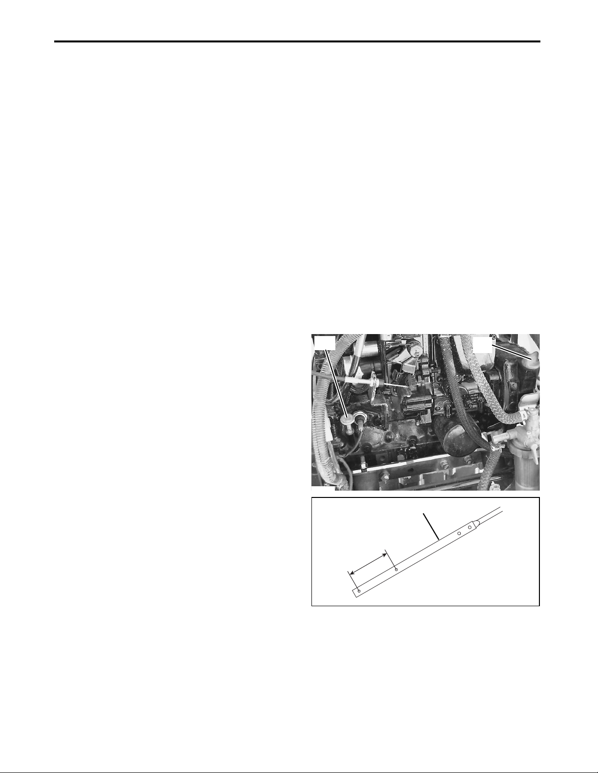
14. PERIODIC SERVICE
■ Check the Engine Oil Level
IMPORTANT: Avoid damage.
●ALWAYS check the oil level before day's operation. If the oil level is low, a serious engine problem can occur.
●ALWAYS check the oil level before operation.
●ALWAYS check the oil level when the engine is
cold and not running.
●ALWAYS maintain the oil level between the lower and the upper marks.
●ALWAYS shut the engine down and allow to cool before adding the engine oil.
1. Park the tractor safely and securely.
2. Open the hood.
IMPORTANT: Avoid damage.
●Prevent dirt and other contaminants from entering the engine. Clean the area around the dipstick before removing it.
3. Remove the dipstick. Clean the dipstick blade
with a clean paper towel or shop rag.
4. Insert the dipstick completely.
5. Remove the dipstick again.
6. Check the oil level on the dipstick. The oil level
should be kept between the lower and the upper
marks on the dipstick.
7. If the oil level is low:
(1) Remove the oil fill cap.
(2) Refill the specified oil until the oil level reaches
between the lower and upper marks.
(A) Dipstick
(B) Oil fill cap
(a) Upper mark
(b) Lower mark
NOTE
●NEVER overfill the engine with oil.
8. If the oil level exceeds the upper mark, drain the
oil to a proper level.
9. Replace the dipstick.
10.Close the hood.
(A)
P3014912a
P3014911a
(B)
(A)
(a)
(b)
Sc2400 Operator’s Manual
14-7
Page 97

14. PERIODIC SERVICE
■ Check the Transmission/Hydraulic Oil Level
IMPORTANT: Avoid damage.
●ALWAYS check the oil level before day's operation. If the oil level is low, a serious transmission problem can occur.
●ALWAYS check the oil level before operation.
●ALWAYS check the oil level when the engine is
cold and not running.
●ALWAYS maintain the oil level between the high and low marks.
●ALWAYS shut the engine down and allow to cool before adding the transmission/hydraulic oil.
1. Park the tractor safely and securely. Allow the
tractor to cool off for at least 1 hour.
2. Tilt the seat forward.
IMPORTANT: Avoid damage.
●Prevent dirt and other contaminants from entering the transmission. Clean the area around the dipstick before removing it.
3. Remove the dipstick.
4. Thoroughly wipe the dipstick clean with a rag.
Only insert the dipstick into the hole. At this point,
do not fasten the dipstick into the hole.
NOTE
●The dipstick is integrated with the oil fill cap.
5. Check the oil level on the dipstick. The oil level
should be between the high and low marks on the
dipstick.
6. If the oil level is low:
Clean the area around the oil fill cap, then remove
the fill cap from the transmission housing.
Add Cub Cadet Hydraulic/Transmission Fluid
through the fill port until the oil level is
appropriate.
NOTE
●NEVER overfill.
(A)
P3014913
(a)
(b)
(B)
P3014914
7. Replace and tighten the dipstick.
(A) Oil fill cap
(B) Dipstick
(a) High mark
(b) Low mark
14-8
3014928
Sc2400 Operator’s Manual
Page 98

14. PERIODIC SERVICE
■ Check the Radiator Hoses and Clamps
! WARNING! WARNING
●ALWAYS stop the engine, allow it to cool and remove the key from the starter key switch before checking the radiator hoses and clamps.
1. Park the tractor safely and securely.
2. Open the hood.
NOTE
●Visually check the hoses for cracks and wear.
Squeeze the hoses to check for evidences of
deterioration. Hoses should not be hard and brittle
nor soft or swollen.
3. Check the upper radiator hose for any damage
including cracking. Replace the damaged hose.
4. Check the hose clamps as necessary.
5. Check the lower radiator hose for any damage
including cracking. Replace the damaged hose.
6. Check the hose clamps as necessary.
7. Close the hood.
(A) Upper radiator hose
(B) Hose clamps
(C) Lower radiator hose
P3014915
(B)
(A)
(B)
(B)
(C)
■ Clean the Radiator Cooling Fins and Screen
! CAUTION
●ALWAYS stop the engine and remove the key from the starter key switch before cleaning the radiator cooling fins and screen.
! WARNING! WARNING
Avoid injury. Compressed air can cause debris and dirt to powerfully fly a long distance:
●NEVER allow bystanders near the tractor.
●When using compressed air for cleaning,
ALWAYS ensure adequate air inflow to prevent
engine overheating, or wear protective
goggles.
●Reduce compressed air pressure to 30 psi (210 kPa).
Sc2400 Operator’s Manual
14-9
P3014916
(B)
Page 99

14. PERIODIC SERVICE
IMPORTANT: Avoid damage.
●The cooling fins, screen must remain clean in order to ensure adequate air inflow to prevent engine overheating.
1. Park the tractor safely and securely.
2. Allow the engine to cool completely.
3. Open the hood.
4. Lift up the intake air hose and then move it to the
sideway. Then, raise the radiator cooling screen
and remove it.
5. Clean the screen with compressed air, brush or
cloth.
6. Remove any dirt and debris from the fins at the
front and rear of the radiator and from the fan with
compressed air.
IMPORTANT: Avoid damage.
●When using compressed air, be careful not to damage the cooling fins.
7. Reinstall the radiator cooling screen and the
intake air hose.
8. Close the hood.
(A) Radiator cooling screen
(B) Intake air hose
P3014917
(A)
(B)
■ Clean the Rear Grille Screen
IMPORTANT: Avoid damage.
●Clean the grille to prevent the engine from
overheating and ensure adequate air inflow.
1. Check the grille for dirt, grass chippings and
debris.
2. Clean the grille with a brush or cloth.
(A) Rear grille screen
3014915a
(A)
14-10
Sc2400 Operator’s Manual
Page 100

14. PERIODIC SERVICE
■ Check the Cooling System
! WARNING! WARNING
●ALWAYS allow radiator to cool before removing the radiator tank cap. The radiator will be hot and can cause burns. When the radiator tank cap is removed, pressure build-up in the cooling system can cause the coolant to spray out explosively.
●ALWAYS shut the engine down and allow it to cool.
●NEVER remove the radiator tank cap before the radiator and the engine are sufficiently cool such that they can be touched with bare hands.
●Loosen the radiator tank cap carefully to the
first stop, allowing excessive pressure to
escape. Only then remove the radiator tank
cap. If the tractor is equipped with a coolant
reserve tank, add coolant or water to the
reserve tank, not to the radiator.
1. Park the tractor safely and securely.
2. Allow the engine to cool down.
3. Open the hood.
4. Check that the coolant level of the reserve tank is
between the FULL line and the LOW line.
5. When necessary, remove the reserve tank cap
and add the coolant.
6. Add pre-diluted coolant which is a 50:50
antifreeze-water mixture.
Use High Quality Permanent Type Antifreeze
(Ethylene Glycol with corrosion and rust inhibitor
chemicals).
7. Reinstall the reserve tank cap.
8. Close the hood.
(A) Reserve tank
(B) Reserve tank cap
(a) FULL line
(b) LOW line
3014913
(B)
(A)
(a)
(b)
Sc2400 Operator’s Manual
14-11
 Loading...