

Page 1
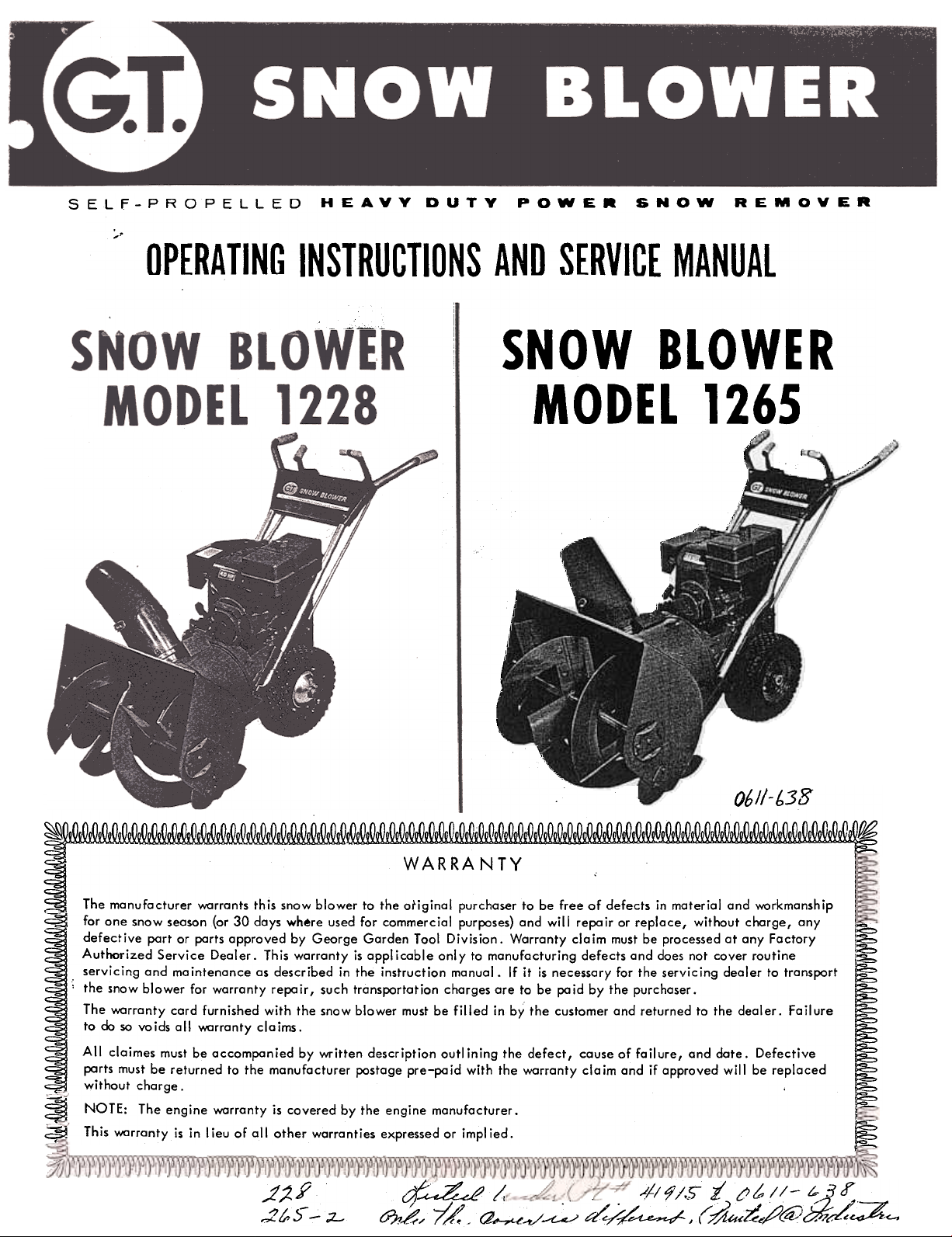
HEAVY DUTY POWER SNOW REMOVER
;..
OPERATING INSTRUCTIONS AND SERVICE MANUAL
.' ~~
~ -SNOW BLOWER
MODEL 1265
~/ I
(- r \ (
=-
( r
)---"" /
"'
\
"""
I, 06//-b3S
~~~
WARRANTY
The manufacturer v.1:Irrants this snow blower to the original purchaser to be free of defects in material and v.1:Irkmanship
for one snow season (or 30 days where used for commercial purposes) and will repair or replace, without charge, any
~
defective part or parts approved by George Garden Tool Division. Warranty claim must be processed at any Factory
Authorized Service Dealer. This warranty is applicable only to manufacturing defects and does not cover routine
.servicing and maintenance as described in the instruction manual. If it is necessary for the servicing dealer to transport
..the snaw blower for warranty repa ir, such transportation charges are to be po id by the purchaser.
The v.1:Irranty card furnished with the snow blower must be filled in by the customer and returned to the dealer. Fail ure
to do so voids all v.1:Irranty claims.
All claimes must be accompanied by written description outlining the defect, cause of failure, and date. Defective
parts must be returned to the manufacturer postage pre-pa id with the v.1:Irranty cia im and if approved will be replaced
without charge.
~ NOTE: The engine v.1:Irranty is covered by the engine manufacturer.
~ This v.1:Irranty is in I ieu of all other warranties expressed or impl ied.
-
~
SELF-PROPELLED~~~
I
.)'
;2. Y
,;Z to ~ -;;L-
&J?1~~t:~./~ d/~-~ (~u:Z;;~gj:::z.:c-.
Page 2
PAGE
PAGE
r
,-over
Table of Contents. ..
1 Snowblower and Model 265-2
Transmission Unit Parts Diagram. ...
...2
Parts List.
Section I, Assembly Instructions for
Models 228 and 265-2 2,3,4 Parts List (con't), Continuation of
Operating Instructions.
Section II, Pre-Starting Instructions. .: .4
Section V f Lubrication. ..
Section III, Rules for Safe Operation. ..4-5
Section VI, Adjustment, Repair or
Section IV I Operating Instruction.
.5 and 9
Replacement.
SECTION
ASSEMBLY INSTRUCTIONS FOR
6-7
8
9
10
.10-12
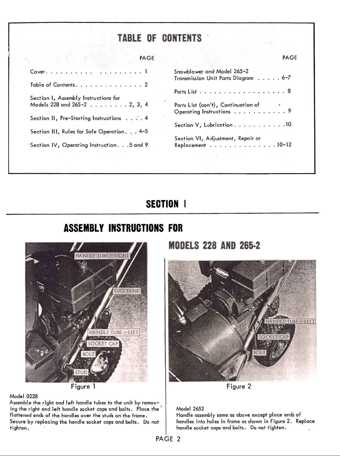
Figure 1
Model 0228
Assemble the right and left handle tubes to the unit by remov-
ing the right and left handle socket caps and bolts. Place the!
flattened ends of the handles over the studs on the frame.
Secure by replacing the handle socket caps and bolts. Do not
tighten.
Figure 2
Model 2652
Handle assembly same as above except place ends of
handles into hol es in frame as shown in Figure 2. Replace
handle socket caps and bolts. Do not tighten.
PAGE 2
Page 3
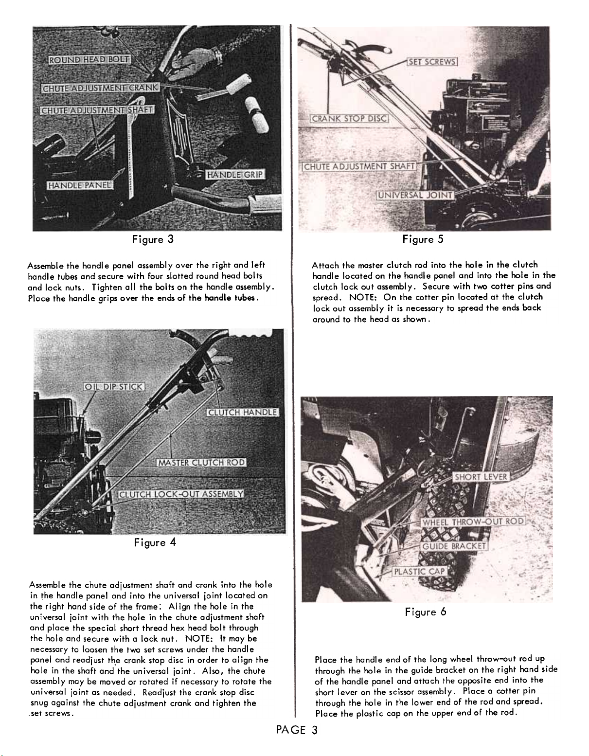
Figure 3 Figure 5
Assemble the handle panel assembly over the right and left
handle tubes and secure with four slotted round head bolts
and lock nuts. Tighten all the bolts on the handle assembly.
Place the handle grips over the ends of the handle tubes.
Figure 4
Attach the master clutch rad into the hale in th~ clutch
handle located on the handle panel and into the hale in the
clutch lock aut assembly. Secure with two cotter pins and
spread. NOTE: On the cotter pin located at the clutch
lock out assembly it is necessary to spread the ends back
around to the head as shawn .
Assemble
Figure
PAGE
the chute adjustment shaft and crank into the hole
in ~he handle ponel and into the universal joint located on
the right hand side of the frame: AI ign the hole in the
universal joint with the hole in the chute adjustment shaft
and place the special short thread hex head bolt through
the hole and secure with a lock nut. NOTE: It may be
necessary to loosen the two set screws under the handle
ponel and readjust th.e crank stop disc in order to al ign the
hole in the shaft and the universal joint. Also, the chute
assembl y may be moved or rotated if necessary to rotate the
universal joint os needed. Readjust the crank stop disc
snug against the chute adjustment crank and tighten the
setscrews.
6
Place the handle end of the long wheel throw-out rod up
through the hole in the guide bracket on the right hand side
of the handle panel and attach the opposite end into the
short lever on the scissor assembly. Place a cotter pin
through the hole in the lowe~ end of the rod and spread.
Place the plast i c cap on the upper end of the rod.
3
Page 4
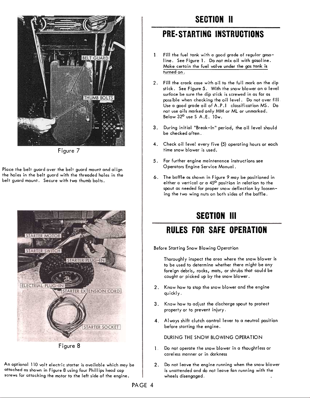
Figure 7
Place the belt guard over the belt guard mount and align
the holes in the belt guard with the threaded holes in the
bel t guard mount. Secure with two thumb bol ts.
SECTION II
PRE. STARTING INSTRUCTIONS
Fill the fuel tank with a good grade of regular gaso-
1
line. See Figure 1. Do not mix oil with gasoline.
Make certain the fuel valve under the gas tank is
turned on.
Fill the crank case with ail to the full mark an the dip
stick. See Figure 5. With the snow blower on a level
surface be sure the dip stick is screwed in as for as
possible when checking the oil level. Do not over fill
Use a good grade oil of A.P.I classification MS. Do
not use oils marked only MM or ML or unmarked.
Below 3~ use S A.E. lOw.
During initial "Break-In" period, the oil level should
3.
be checked often.
oil leve! every five (5) operating hours or each
time snow blower is used.
For further engine mointenance instructions see
Operators Engine Service Monual.
baffle as shawn in Figure 9 may be positianed in
either a vertical or a 450 position in relation to the
spout as needed for proper snow deflection by loosen-
ing the two wing nuts on both sides of the baffl e.
Figure 8
An optional 110 volt electric starter is available which may be
attached as shown in Figure 8 us ing four Ph i II ips head cap
screws for attaching the motor to the left side of the engine.
SECTION III
RULES FOR SAFE OPERATION
Before Storting Snow Blowing Operation
Thoroughl y inspect the area where the snow blower is
to be used to determine whether there might be any
foreign debris, rocks, mats, or shrubs that could be
caught or picked up by the snow blower.
Know how to stop the snow blower and the engine
quickly.
Know how to odjust the discharge spout to protect
property or to prevent injury.
Always shift clutch control lever to a neutral position
before starting the engine.
THE SNOW BLOWING OPERATION
Do not operate the snow blower in a thought I ess orcarel
1
ess manner or in darkness
Do not leave the engine running when the snow blower
is unattended and do not leave fan running with thewheels
disengaged.
2.
Check
4.
5.
6.The
2.3.
4.DURING
2.PAGE
4
Page 5
Never over-speed the engine. Excessive operoting speed
or tompering with the governor on the engine con be
dangerous.
4.
Stop snow blowing operation when onother person
opproaches the discharge side or comes near the intake
snow reel. Also, be constantly alert as to the direction
of the snow discharge to prevent damage to autos,
buildings, etc.
Never put hands or feet near rotating parts, using
special caution to keep away from intake reel, blower
fan, belts, chains, and pulleys. Never work on the
snow blower while the engine is running. Disconnect
the spark plug wire before doing ony work on the snow
blower.
Use extreme coution when using the snow blower on
slopes or inclines.
Never fill the gasoline tank while the engine is runn-
ing or while the engine is hot. Wipe off any spilled
gasoline before starting the engine.
Never operate the snow blower engine without proper
ventilation.
Check all screws, nuts and bolts at frequent intervals
9.
to be sure thot the snow blower is in a safe operating
condition.
SECTION IV
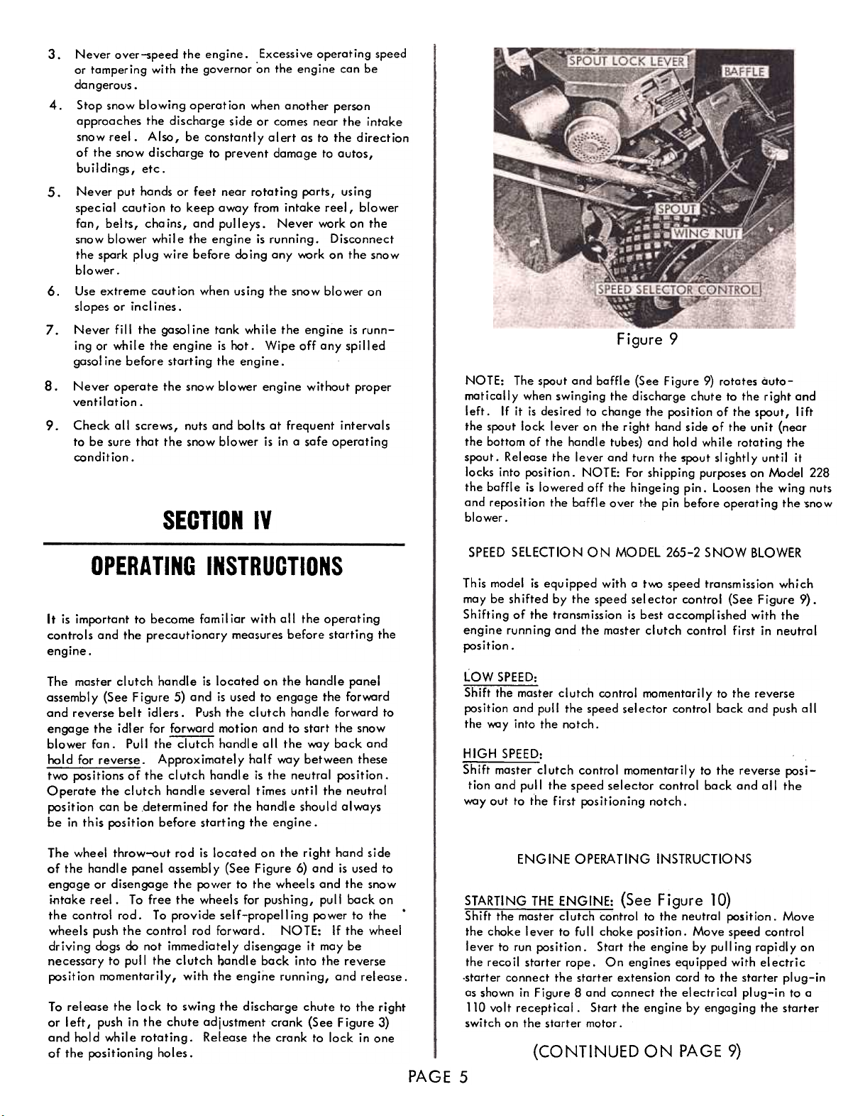
Figure 9
NOTE: The spout and baffle (See Figure 9) rotates automotically when swinging the dischorge chute to the right ond
left. If it is desired to change the position of the spout I lift
the spout lock lever on the right hand side of the unit (near
the bottom of the handle tubes) and hold while rotating thespout.
Rei eose the I ever and turn the spout sl ightl y unt il it
locks into position. NOTE: For shipping purposes on ,'.;.odel 228
the baffle is lowered off the hingeing pin. Loosen the wing nutsand
reposition the baffle over the pin before operating the ~now
blower.
SELECTION ON MODEL 265-2 SNOW BLOWER
INSTRUCTIONS
This model is equipped with a tv.\:> speed transmission which
moy be shifted by the speed selector control (See Figure 9).
It is important to became familiar with all the operating
controls and the precautionary measures before starting the
engine.
The master clutch handle is located on the handle panel
assembly (See Figure 5) and is used to engage the forward
and reverse belt idlers. Push the clutch handle forward to
engage the idl er for forward motion and to start the snow
blower fan. Pull the clutch handle all the way back and
hold for reverse. Approximately half way between these
twa positions of the clutch handle is the neutral position.
Operate the clutch handle several times until the neutral
position can be determined for the handle should always
be in this position before starting the engine.
The wheel throw-out rod is located on the right hand side
of the handl e panel assembl y (See Figure 6) and is used to
engage or disengage the pav{er to the wheels and the snow
i~take reel. To free the wheels for pushing, pull back on
the control rod. To provide self-propelling pawer to the'
wheels push the control rod forward. NOTE: If the wheel
driving dogs do not immediately disengage it may be
necessary to pull the clutch ~andle back into the reverse
position momentarily, with the engine running, and release.
To release the lock to swing the discharge chute to the right
or left, push in the chute adjustment crank (See Figure 3)
and hold while rotating. Release the crank to lock in one
of the positioning holes. (CONTINUED ON PAGE 9)
Shifting of the tronsmission is best accompl ished with the
engine running and the master clutch control first in neutral
position.
LOW SPEED:
Shift the master clutch control momentarily to the reverse
position ond pull the speed selector control bock and push all
the way into the notch.
HIGH SPEED:
Shift master clutch control momentarily to the reverse posi-
tion and pull the speed selector control back and all the
way out to the first positioning notch.
ENGINE OPERATING INSTRUCTIONS
STARTING THE ENGINE: (See Figure 10)
Shift the master clutch control to the neutral position. Move
the choke lever to full choke position. Move speed control
lever to run position. Start the engine by pull ing rapidly on
the recoil starter rope. On engines equipped with electric
-starter connect the starter extens ion cord to the starter pi ug-in
as shown in Figure 8 and connect the electrical plug-in to a
110 volt receptical. Start the engine by engaging the starter
switch on the starter motor.
3.
5.6.7.
8.
SPEED
OPERATING
PAGE 5
Page 6

Page 7

~ ~ 1-""--8
.t 143~ ~~, "'8
"'
)
~~~ ~~l ~ ~~;;$
~ /0' /11' \1r ~ ~~=~~~---<§
"'W
/
35 " "D ".. J~~~~~~ 8
~~~~~: ~~ @
\~-7-- -~ I ..-~ -13 7
-~~~ ~
I
/'~
I
~5 I ~2:
IS! -~~
150 153] 1 :: §
~7 44 1,--':4"2'
.:~~--:::~~
f--t48\e
~~--::::~.e.
~ / .
/. .~
f ~~
(
~-;T-
~~-I -@
"-
"@
/~Q
/ ~
"@~(
~
@
@'(§) <
(
(i5) ,
~~.
~- -
..~ ~~@
~T,
--:-\t-- -
~
cr
1
!~
0
J
,
~~:::==:~~ ~
"""~V
9
"'"
"e
~~~~
~_.
Page 8

PARTS LIST
Ref.
No.
10
11
12
13
14
15
16
17
18
18
19
20
21
22
23
24
25
26
27
27
28
29
30
31
32
32
33
33
34
35 40468
35 40201
36 60693
37 40066
37 40150
38 60718
39 40031
39 40490
40 40069
41 20123
42 40072
Port
No.
40441
1
2
61758
61449
3
4
21668
40112
5
41144
6
7
40021
40153
8
9
20521
60799
40151
60046
60026
40081
40041
40033
40032
22171
22193
40052
40079
40156
40035
20533
50045
40148
40065
40062
40225
40442
20116
40435
40056
40105
40155
60670
60764
40042
43 40071
44 40050
45 ' 40073
46 ! 40299
47
I 40040 48 22173
49 40004
50 40047
51 40245
52 40048
53 40076
60053
54
40097
55
56
20100
57
40149
60765
58
40085
59
40087
60
61
61111
61
60149
Thumb Bolt 5/16 x 3/4 (Pltd.)
Belt Guard
Belt Guard t.'.)unt
Belt Guard t.'.)unt Bond
Hex. Hd. Bolt 5/16 x 5/8
Whizlack (Pltd.)
Bolt, 1;'4-28 x 3/8
Belt, 4L-360 (Special)
Lacknut, Rev. (Pltd.)
Farward Belt Restrictar
Boll Bearing Idler
Hex Hd. t.'.)chine Bolt
5/16 x 5/8 (Pltd.)
Reverse Arm Retainer
Reverse Arm
Carriage Bolt 5/16 x 1-3/4 Sh.
Sq. Neck (Pltd.)
Belt, 4L-400 (Special)
Pulley, 8" "'V" Type
Pulley, 7-1/2 Flat Type
Shaft, 20 M M Fan
Shaft, Fan
Spring Pin 5/16 x 1-1/2
Hex Head Machine Bolt 5/16 x
1-3/4 (Pltd.)
S.A.E. Washer, 5/16 (Pltd.)
Cotter Pin 1/8 x 1 (Pltd.)
Axle Collar (Pltd.)
Spring Pin 1/4 x 1-1/2
Std. Wrought Washers 5/16 (Pltd.
Nylack Nuts 1/4 (Pltd.)
Round Heod Stave Bolts 1/4.x
1-1/2 (Pltd.)
Raund Head Stove Bolts 1/4 x
1-3/4 (Pltd.)
Shear Bol t
Shear Bolt Collar.
Bushing Chain Guard
Hex Head Bolt 1/4 x 1/2 (Pltd.)
Lackwcsher 1/4 Spring Type
Lackwcsher 1/4 Spring Type
Chain Guard with Bushing
Long Choin Guard
Carriage Bolt 1/4 x 1/2 Sh. Sq.
Neck (Pltd.)
Chain '40-108 P
Chain with Repoir Link '40-118P
Rear Chain Protector
Hex Nut 1/4"
Hex Nut 1/4" (Pltd.)
20 T. Sprocket with Hub
Wheels
Wheel, Right Pneumatic
Taathed Wheel Bushing
Clutch Dog Caver (Right)
Clutch Dog Sleeve
Clutch Dag, Sliding
Spring Pin, 5/16 x 2
Clutch Dags, Pinned
Oil Seal 1 x 1-7/16
Idler Spring
Belt Guard Plate
Engine Pulley
Set Screw
Lockwasher 5/16 Ext. Shake
Spring Pin 1/4 x 1
Hex Head Machine Bolt 5/16 x
1-1/2 (Pltd.)
Chain Oper. Chute Pulley
Tarsian Spring
Handle Socket Caps
5/16 Lackwcsher (Pltd.)
Cable Oper. Chute Pulley
Coble Hald Down Washer
1/4 x 1/2 Carriage Bolt (Pltd.)
Spout Tube Assembly
Spout Tube Assembly
aly.
02282652
2
1
1
1
7
4
1
12
10
1
2
4
1
8
8
1
2
6
7
4
5
1
2
2
2
2
2
2
2
1
1
1
5
2
2
9
1
2
12
1
1
Ref.
No.
'2
1
1
1
8
4
1
1
2
4
1
1
\
4
7
8
I
2
6
7
4
~
1
2
1
2
2
2
2
2
1
1
1
5
2
2
iO
1
2
13
1
1
1
Part
No
21272
62
62
20185
40100
63
64
60044
60181
64
40091
65
60038
66
60010
67
60\48
67
60009
68
60\47
68
2\269
69
20273
69
60004
70
71
40084
419\9
72
73
4006\
400\8
74
20087
75
20\90
75
40027
76
77
60728
':i)143
17
78
40118
20030
79
40098
80
40089
81
40024
82
40019
83
60015
86
86
60154
20030
88
20108
89
60180
89
90
20505
91
40160
92
60005
92
60144
93
40495
94
20110 Coble Roller
95
40108 Coble Roller Bushing
96
60051 Coble Roller Tightening Bracket 1
97
60014 Blower Housing and Chute Assembly 1
97
61762 Blower Housing and Chute Assembly
98
40142 Special Hex Key 1
99
20266 Coble
99
20263 Coble
61757 Engine Bose and Frome Assembly
100
61568 Engine Bose and Frome Assembly
100
20150 Worm R. H. 1 T.
101
20644 WarmR. H. 3T.
101
40068 Bolt Hex Head 5/16 x 3/4 (Pltd.)
102
103
60056 Clutch lockout Assembly
40163 Thrust Washers
104
105
40023 Boll Bearing
60045 Engine Bose Bock Plate
106
107
20514 Axle (1")
107
20163 Axle (1")
108
40474 Gear Housing
108
40184 Gear Housing
40025 Oil Seal 20 M M x 1-1/8
109
40060 Plugl/4N.P.T.F.SquareHead
110
20124 C:lutch Dog Cover (left)
111
112
20114 left Wheel Collar
113
40164 Thrust Bearing
114
20162 Worm Gear 28 T. (1 T.)
114
60185 Worm Gear with Bushing
40099 Worm Spacer
115
115
40193 Worm Spacer
116
40467 Gasket, Gear Housing
116
40186 Gasket, Gear Housing
117
40475 Gear Housing lid
Description
Baffle
Boffle
Carriage Bolt 5/16 xl Sh. Sq.
Neck (Pltd.)
Chute Collar
Chute Collar
Stove Bolt 1/4 x 5/8 Round
Head (Pltd.)
Special Wing Nut
Reel Shaft Assembly
Reel Shaft Assembly
Scoop Assembly
Scoop Assembly
Front Chain Cover
Front Chain Cover
Sprocket Guard
Washer, 25/32 x 1-1/4 x 1/32
Bal t, Special Step
Press in Oiler
Fan Costing, Top
Reel Paddle
Reel Paddle
Bushing Oilite 3/4 x 1-1/32 x
1-1/8
Reel
Reel
Special Step Bolt (Pltd.) 1
Reel Adjusting Plate 1
Flanged Wizlack I-Jut 5/16 (Pltd.) 16
Felt Wick 1
Bushing, Oilite 20 M M x 1-1/32
x3/4l. 2
Fan Costing Bottom 1
Disc Wheel 2
Disc Wheel
Disc Wheel Adjusting Plate (l)
Coble Roller Cover
Coble Roller Cover
Skids
Carriage Bolt 5/16 x 3/4
Fan Assembly
Fan Assembly
Screw, Hex Head Machine
.5/16 xl
aty. Gty.
02282652Description
i
2
1
j
2
2
2
1
2
12
2
7
1
2
2
2
2
2
2
2
1
1
2
16
I
2
2
1
1
2
12
7
1
/~,
2
4
1
1
2
1
1
1
1
aly.
""'
1
~
PAGE 8
Page 9

PARTS LIST
Ref.
No.
117
118
119
120
121
122
123
124
125
126
127
128
129
130
131
132
133
134
135
135
136
136
137
137
138
139
140
141 i
150
141
142
143
144
145
146
148
149
151
Port
No.
40185
20097
60033
60018
40039
60055
60019
60016
41917
40165
40110
40139
40140
40070
60326
20265
22179
22190
40044
40217
41911
41920
41912
41921
41913
41316
22230
41916
41938
22176
61576
40132
40078
60343
40198
40341
61752
40320
Description
Gear Housing Lid
Clutch Scissor Link
Right Hand Clutch Yake
Clutch Scissor Arm (Right)
dutch Scissor Spring
Left Hand dutch Yake
Clutch Scissor Arm (Left)
dutch Scissor Bar Assembly
Chute Adjusting Chain
Chain Connecting Link
Chain Mounting Bolt
Chute Chain Connecting Pin
Hair Pin Cotter,
Flartged Whizlack Bolt 1/4 x
1/2 (Pltd.)
Double Spring Pin Assembly
Key, 3/16 Sq. x 1-1/2
Wheel Thra""ut Rod
Master dutch Rod
Handle Grips 1"
Handle Grips 1-1/4"
Handle L. H.
Handle L. H.
Handle R. H.
Handle R. H.
Cap, Plastic 5/16 x 2-1/2
Screw, Self Tapping Slatted Head
Universal Joint
Engine 4 H. P. Tecumseh Lauson
Model 'H40
Engine 6 H. P. Tecumseh Lauson
Model 'H60
Chute Adjusting Shaft (Pltd.)
Crank Stop Disc Assembly
Push Nut
Plastic Handle
Chute Adjusting Crank
Crank Pivot Tube and Plate
Compression Spring (Pltd.)
Chute Adjusting Sprocket Assembly
Handle Caps, Plastic
Oty. Oty.
0228 2652
3
1
1
1
1,
2
1
2
1
1
1
1
1
1
1
1
1
2
158
159
160
161
162
163
164
165
166
167
168
169
170
171
172
173
174
175
176
177
178
179
180
181
182
183
Part'
No.
40250
40480
22181
22184
41362
61753
61574
40489
40173
40248
40220
40251
20228
60218
40177
40183
41302
40179
40180
40045
22194
41304
40181
61397
20164
60076
20156
40236
20157
21673
40226
40249
40496
Description
Spring Pin 1/8 x 3/8
Special Bolt 1-1/4 (Pltd.)
Chute Chain Caver
Sprocket Spacer Bushing
Sintered Bronze Bushing
Handle Panel Assembly
Handle Panel Assembl y
Wheel Complete (l. H.)
Washer 51/64 x 1-1/8 x .015
Side Caps
Spring Pin 5/16 x 1-3/4
Gasket, Cap
4OT. Gear, 20MMBore
Heavy Duty, Spring Pin
Spline Shaft
lack Ring External (1-1/8")
Cluster Gear
Spring, Cluster Gear
Steel Ball, 3/16" Dia.
Plastic Knob
Arm, Shift
Spring, Ext. (Shift Arm)
Hairpin Cotter
Upper Shift Arm Assembly
Inside Shift Collar (lever)
Inside Shift lever
Shifting Block
Bushing, Oilite
30 T. Spur Gear
39 T. Spur Gear -I" Bore
Washer (TRE-1625)
Bolt 1/4-28 T. x 1/2 Hex Head
Screw, Hex Head Type-B 5/16
Oty. Oty.
0228 2652
2 2
1 1
1 1
1
1 1
1
1 1
1
1
2
1
2
1
2
1
1
1
1
1
1
1
1
2
1
1
1
6
Ref.
No.
1
1
1
1
1
1
1
1
1
1
1
1
3
152
153
154
155
156
157
157
2
1
1
2
x 1-1/2"
* 39
*158
* 39
*
2
61577
61578
61579
61,500
OptionQI Equipment ot Additionol Cost
Wheel with Tire Stud.
Wheel with Tire Stud. L. H
Wheel with Tire Stud. R. H
Starter Matar Kit 110 Valt
2
(CONTINUED FROM PAGE 5
Figure 10
SECTION IV
OPERATING INSTRUCTIONS
,. ,
NOTE: The three-prong electrical plug-in on the extension
cord is to be used with a grounded circuit electrical outlet.
If no grounded three-prong outlet is available use the two-
prong adapter provided the ground wire on the adapter is
properly grounded. As the engine starts and begins to worm
up gradually return the choke lever to the "No Choke"
position.
NOTE: If the temperature is below + 100 F. depress and
hold the black button (primer) on the carburetor and pull
the engine over slowly with the starter rope. Release the.
button and start the engine as outlined above.
STOPPING THE ENGINE:
~
To stop the engine move the speed control lever to the stop
position or close the fuel shut-off valve under the gasoline
tank. The spork pi ug wire may also be removed to prevent
accidental starting while unattended.
PAGE 9
Page 10

V
LUBRICATION
LUBRICATE THE PARTS PERIODICALLY AS ILLUSTRATED IN
FIGURES 11,12 and 13.
LUBRICATION POINTS:
The following points are to be lubricated every five hours
of operation with S.A.E., 20 weight I ight duty oil, unless
otherwise noted.
Clutch Lock-out Assembly
1 .
2.
Reverse. Arm
3.
Wheel Clutch Dogs
4.
Clutch Yokes
Wheels
5.
6.
Discharge Spout
7.
Blower Housing.
8.
Reel Chain
9.10.
Chute Adjustment Cha in
Chain Guard Bushing
11 .12.13.14.
Universal Joint
Reel and Shaft Bearings
Cable Rollers
Gear Housing- With the belt guard removed turn the
holes in the pulleys to the bottom to expose the gear
housing fill plug. The oil level in the gear housing
should be kept at or above this fill plug. Drain and
refill with heavy duty GX-90 Gear Lubricating Oil
once each season or approximatel y 25 hours use.
Figure 12
SECTION
Figure 1
Figure 13
SECTION VI
ADJUSTMENT,
REPAIR OR REPLACEMENT
REEL DRIVE CHAIN ADJUSTMENT:.
Check periodically for undue looseness. To tighten the
chain, first loosen the t~ nuts at each end of the reel,
holding the reel shaft plates. Slide the snow intake reel
forward by rotating the plate near the sprocket end of the
reel with a punch or rod. Hold in the tightened position
and tighten the reel shaft plate bolts and nuts. IMPORTANT:
Adjust both ends of the reel equally to keep the fan shaft
casting in al ignment. Do not tighten the chain too tig~tly.PAGE
10
Page 11

DEPTH ADJUSTMENT:
accessible. Tighten the adjustment nut ta tighten the chain.
CAUTION: Chain should nat be tightened taa tightly.
CABLE ADJUSTMENT:
See Figure 13. Remove cable roller cover. Loosen the
locking bolt on top of the cable roller bracket and tighten
the adjustment bolt on the side.
CAUTION: The cable should not be adjusted too tightly,
but should allow the spout to rotate freely. Retighten the
lacking bait and replace the cable roller caver.
Figure 14
The adjustable shoes may be set lower to prevent picking up
loose stones and foreign material. Also, the disc wheels on
the inside of the scoop may be adjusted to help lift the
scraper blade over small obstructions or may be adjusted to
allow the snow reel to sl ightl y touch the ground for addi-
tional pulling power.
Figure 16
REPLACING SAFETY SHEAR BOLT:
If the intake snow reel should jam causing the safety shear
bolt to shear it may be replaced with a new bolt, furnished
in the parts bag, after removing the broken pieces in the
shaft. NOTE: Always align the hole in collar with the
al ignment grooves on the end of the sprocket sl eeve and
shaft before driving out the broken pin and'replacing the
new bolt.
Figure 15
.Q!UTE CHAIN AND ADJUSTMENT:
To tighten the chute position chain rotate the chute until
the spout is in the straight up position. Tilt the snow blower
forward until the adjustment bolt as shawn in Figure 15 is
CHUTE
PAGE
BELT AND IDLER WHEEL ADJUSTMENT:
CAUTION: For belt adjustment the engine should be stopped
and the spark plug wire removed.
After the machine has been aperated a short time it may be
necessary to readjust the idl ers for proper bel t tension. The
following steps should also be carefully followed when install ing replacement belts.
11
Page 12

.FORWARD BELT IDLER ADJUSTMENT:
With the master clutch control in the forward position
the edge of the reverse orm should be 01 igned with
line "B". As the belts become stretched or in the
installation of the new belt it may be necessary to
readjust the forward belt idler in its adjustment slot to
bring the reverse arm to line "B", in the forward
running position. For adjustment, return the clutch
control lever to the neutral position and loosen the
nut holding the forward belt idler and move the idler
in small steps to the right, and tighten the nut. Again
move the clutch control lever to the forward position
and check for al ignment with line "B". Repeat the
above steps until the proper idler position is accomp-
lished. NOTE: When retightening the nut on the
forward belt idler care should be taken to position the
forward belt restrictor to clear the belt at all points when
the idler pulley is engaged in the running position and it
should also clear the large pulley as shown in Figure 18.
Figure 17REVERSE
ARM ADJUSTMENT:
Remove the belt guard. A belt replacement decal is
located on the ponel behind the reverse arm which is
used to properly position the reverse arm and the idlers.
With the master clutch control in the neutral position
the right hand edge of the reverse arm should be al igned
with line "A" on the decal. The two bolts on the clutch
lock out arm may be loosened to allow adjustment of the
arm up or down as needed to position the reverse arm
to line "A".
REVERSE IDLER ADJUSTMENT:
With the clutch control in the forword running position
check to see that the reverse belt is tight when pulled
up on the rim of the reverse belt idler wheel. Loosen
the bolt on the reverse idler and slide it up or down to
obtain the proper tension. Return the cl utch cont;ol
to the neutral position and position the reverse belt in
the center of the idl er. Check to see thot there is
approximatel y 1/8 inch clearance between the lorge
pulley and the pulley band.
END OF SEASON STORAGE:~--
In the event the engine is to be stored for any length of time
(30 days or more) or at the end of the snow blowing season,
prepare it as outlined in the following steps.
1
Drain gas tank completely by removing fuel line atthe
carburetor or fuel tank, whichever is easier.
Drain the carburetor by pressing up~rd on the bowl
2.
drain.
To protect the engine when storing, remove the spark
plug and inject one ounce of S.A.E. 10 weight oil
through the spark plug hole into the cylinder. Crank
the engine (without starting) several times to spread theoil
over the cylinder walls.
2.
3.
3.
Figure 18
4.
Lubricate ailiubricatian points as outlined in Section 5.
Page 13

CHUTE CABLE
REPLACEMENTAND
REPAIR FOR MODEL
228 AND
265-2
NOTE:
The reference numbers referred to in the following instructions may be found in the parts list
and the exploded view.
REMOVE THE BLOWER HOUSING FROM THE SNOW
BLOWER.
A. Remove the safety shear bait (Ref. No. 28), chain
guard (Ref. No. 33), and disconnect the reel drive
chain (Ref. No. 35) at the chain connecting link.
B. Remove the faur carr~age baits (Ref. No. 91)
fasten the scoop (Ref. No. 58) to the frame. Remo':'e the scoop and reel assembl y intact.
C. Remove the spring pin (Ref. No. 19) and remove
the fan (Ref. No. 92).
D. Remove the set screw which holds the chain pulley
(Ref. No. 54) in place and slide the chain pulley
off the blower housing tube.
E. Remove the blower housing (Ref. No. 97) from the
unit.
CABLE WASHER
CABLE BOLTII
I
"
"
CABLE TRACK
FIGURE A
2. REMOVE THE WORN CABLE.
A. Place the blower housing on a bench with the
cable pulley (Ref. No. 58) exposed as shown in
Figure E.
B. Remove the cable roller cover (Ref. No. 89) and
remove the bolt from the chute collar (Ref. No.
64). See Figure C.
C. Loosen the lock bolt on top o( the cable roller
bracket and adjust the cable adjusting bolt and
cable roller in as far os possible (See Figures C
and D).
D. Remove the special hex key (Ref. No. 98) from
the tube protruding from the blower housing and
slide the cable pulley oway from the blower hous-
ing approximately 3 inches.
E. Loosen the cable mounting bolt (Ref. No. 31)
Figure E and remove the cable ends from the cable
pulley.
F. Pry the chute collar apart (Ref. No. 64) Figure B
ond remove the upper spout assembly (Ref. No. 61)
from the blower housing.
G. Loosen the nut on the cable mounting bolt (Ref.
No. 60) Figure B which fastens the cable to the
upper spout assembly and remove the worn cable.
REPLACE NEW CABLE.
A. Start both ends of the cable through the hol e in
the top of the cabl e track on the upper spout
assembly, (See Figure A). Pull both ends of the
cable through and fasten the loop under the cable
washer (Ref. No. 59) making certain that both ends
of the cable are even.
3.
~
CABLE
FIGURE
UPPER SPOUT ASSEMBLY
-{=~~~
0
CABLE TRACK
/"
7 ,ncc," ,
CHUTE COLLAR
CABLE MOUNTING BOLT
FIGURE B
MODEL 228
CHUTE COLLAR BOLT r
CHUTE COLLAR
DOUBLE ROLLERI
--.0 I~LE ROLLER
CABLE ROLLER BRACKET
ADJUSTMENT BOLT
CABLE LOCK BOLT
C
Page 14

MO DEL
265-2
FIGURE D
CABLE PULLEY
CABLE BOLT
BLOWER HOUSING
FIGURE E
B. With the cable crossed wrap each end of the coble
oround the upper spout in the direction as shown in
Figure B.
C. Start the cable through the holes in the chute
collar from the inside and sl ip the collar aver the
cable track as shown in Figure B. The cable coming from the left side of the spout should enter
through the left hole in the collar. The cable com-
ing from the right side of the spout should enter
through the right hole in the collar. Make certain the cable stays in the track when the chute
collar is replaced.
D. Replace the upper spout assembly onto the blower
housing, slipping the collar over the flanged ring,
and fasten with the chute collar bolt.
PLACING THE CABLE OVER THE CABLE ROLLERS.
A. Rotate the upper spout assembly with the open side
in the opposite direction from the cable pulley side
of the blower housing assembl y. See Figure C and
D.
B. For Model 0228.
Extend the cable from the right side of the spout
assembly over the inside groove of the double
roller (See Figure C) and through the left hole and
the top of the blower housing and down the left
side of the cable pulley. Extend the cable from
the left side of the upper spout across the roller
nearest the chute collar around the inside and
around the cable adjusting roller, over the double
roller to the right, and down through the hale in
the blower housing and along the side of the cable
pulley.
B. For Model 265-2
Extend the cable from the left side of the upper
spout assembly over the roller on the right side of
the cable roller bracket (See Figure D) and through
the right cable hol e in the top of the blower hous-
ing. Extend the cable from the right side of the
spout assembly across the center cable roller, back
and around the cable adjustment roller and over the
cable roller on the left side of the cable roller
bracket and down to the left hole in the top of the
blower housing.
C. Turn the cable pulley with the cable bolt (Ref: No.
31) toward the bottom of the blower housing (See
Figure E).
D. Put the ends of the cabl e up through the hol es in
the bottom of the cabl e pulley and cross the ends
up and over the cabl e bolt and under the washer.
The right cable extends up through the left hole.
Pull the cable tight and tighten the cable bolt and
nut I mak ing sure the cabl e rema ins in the track
around the cable pulley.
E. Replace special hex key and slide cable pulley
back into place.
F. Tighten cable with adjusting cable roller.
REPLACE THE BLOWER HOUSING.
A. Reverse the steps outl ined in Step 1 to replace the
blower housing and parts to the snow blower.
4.
5.
GEORGE GARDEN TOOLS DIVISION, 811 So. HAMILTON, SULLIVAN, ILLINOIS
 Loading...