

Page 1
Safe Operation Practices • Set-Up • Operation • Maintenance • Service • Troubleshooting • Warranty
OperatOr’s Manual
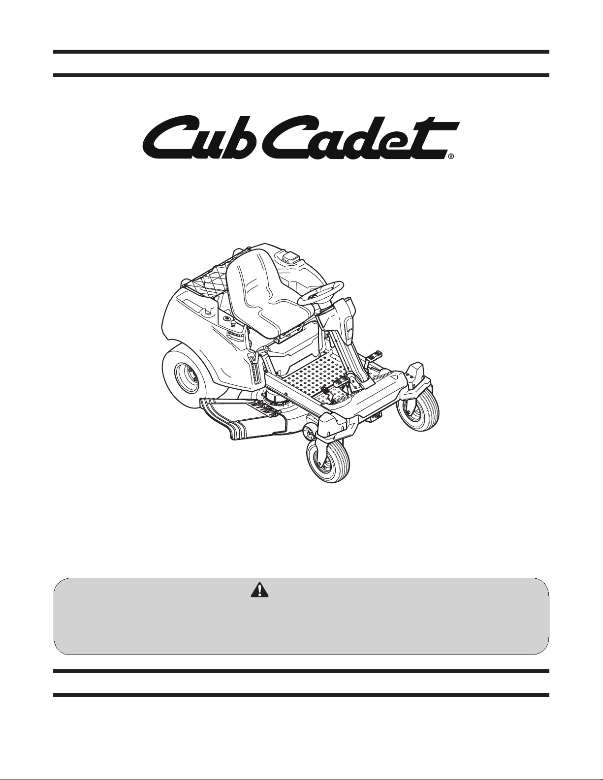
RZT-S Zero
WARNING
READ AND FOLLOW ALL SAFETY RULES AND INSTRUCTIONS IN THIS MANUAL
BEFORE ATTEMPTING TO OPERATE THIS MACHINE.
FAILURE TO COMPLY WITH THESE INSTRUCTIONS MAY RESULT IN PERSONAL INJURY.
CUB CADET LLC, P.O. BOX 361131 CLEVELAND, OHIO 44136-0019
Printed In USA
Form No. 769-08316
(Februar y 27, 2013)
Page 2

To The Owner
Thank You
Thank you for purchasing a Cub Cadet Electric Zero-Turn tractor.
It was carefully engineered to provide excellent performance
when properly operated and maintained.
Please read this entire manual prior to operating the equipment.
It instructs you how to safely and easily set up, operate and
maintain your machine. Please be sure that you, and any other
persons who will operate the machine, carefully follow the
recommended safety practices at all times. Failure to do so could
result in personal injury or property damage.
All information in this manual is relative to the most recent
product information available at the time of printing. Review
this manual frequently to familiarize yourself with the machine,
its features and operation. Please be aware that this Operator’s
Manual may cover a range of product specifications for various
models. Characteristics and features discussed and/or illustrated
in this manual may not be applicable to all models. Cub Cadet
LLC reserves the right to change product specifications, designs
and equipment without notice and without incurring obligation.
Table of Contents
Safe Operation Practices ........................................ 3
Set-Up ....................................................................... 9
Controls & Features ................................................ 11
Operation ................................................................15
Maintenance & Adjustment ................................ 20
1
If you have any problems or questions concerning the machine,
phone your local Cub Cadet dealer or contact us directly. Cub
Cadet’s Customer Support telephone numbers, website address
and mailing address can be found on this page. We want to
ensure your complete satisfaction at all times.
Throughout this manual, all references to right and left side of the
machine are observed from the operating position.
Service .................................................................... 24
Troubleshooting .................................................... 25
Replacement Parts ................................................ 27
Attachments & Accessories .................................. 28
Warranty ................................................................ 32
Record Product Information
Before setting up and operating your new equipment, please
locate the model plate on the equipment and record the
information in the provided area to the right. You can locate the
model plate by standing at the left side of the tractor, pivoting
the seat forward and looking down at the seat frame. This
information will be necessary, should you seek technical support
via our web site or with your local Cub Cadet dealer.
Model NuMber
Serial NuMber
Product Registration and Customer Support
Please register your product on our website, www.cubcadet.com.
If you have difficulty assembling this product or have any questions regarding the controls, operation, or maintenance of
this machine, you can seek help from the experts. Choose from the options below:
◊ Visit us on the web at www.cubcadet.com
See How-to Maintenance and Parts Installation Videos at www.cubcadet.com/tutorials
◊ Locate your nearest Cub Cadet Dealer at (877) 282-8684
◊ Write to Cub Cadet LLC • P.O. Box 361131 • Cleveland, OH • 44136-0019
2
Page 3
Important Safe Operation Practices
WARNING: This symbol points out important safety instructions which, if not followed,
could endanger the personal safety and/or property of yourself and others. Read and follow
all instructions in this manual before attempting to operate this machine. Failure to comply
with these instructions may result in personal injury.
When you see this symbol, HEED ITS WARNING!
CALIFORNIA PROPOSITION 65
WARNING! Battery posts, terminals, and related accessories contain lead and lead
compounds, chemicals known to the State of California to cause cancer and reproductive
harm. Wash hands after handling.
DANGER: This machine was built to be operated according to the safe operation practices in
this manual. As with any type of power equipment, carelessness or error on the part of the
operator can result in serious injury. This machine is capable of amputating fingers, hands,
toes and feet and throwing objects. Failure to observe the following safety instructions could
result in serious injury or death.
WARNING: When using electric tractors, basic safety precautions should always be followed
to reduce the risk of fire, electric shock, and personal injury. These basic precautions include
the following pages:
READ ALL INSTRUCTIONS
2
48 Volt Battery System
Servicing requires extreme care and knowledge of the system and should be performed only by a qualified
service technician. For repair service take the tractor to your nearest authorized service dealer. Always use original
equipment manufacturer’s (OEM) replacement parts when servicing.
General Operation
1. Read, understand, and follow all instructions on the
machine and in the manual(s) before attempting to
operate. Keep this manual in a safe place for future and
regular reference and for ordering replacement parts.
2. Be familiar with all controls and their proper operation.
Know how to stop the machine and disengage them quickly.
3. This machine is a precision piece of power equipment,
not a plaything. Therefore, exercise extreme caution at all
times. This machine has been designed to perform one job:
to mow grass. Do not use it for any other purpose.
4. Never allow children under 14 years of age to operate this
machine. Children 14 and over should read and understand
the instructions and safe operation practices in this manual
and on the machine and should be trained and supervised
by an adult.
5. Never allow adults to operate this machine without proper
instruction.
6. Do not charge or operate the tractor in the rain or in wet
areas.
7. In case of a system fault or a complete loss of battery
power the tractor can free-wheel. Depress the brake pedal
to maintain control and stop the unit. Restart the tractor. If
the problem persists, contact your service dealer.
8. Do not mow on wet grass. Reduced traction could cause
sliding.
9. Only responsible individuals who are familiar with these rules
of safe operation should be allowed to use this machine.
10. To help avoid blade contact or a thrown object injury,
keep bystanders, helpers, children and pets at least 75 feet
from the machine while it is in operation. Stop machine if
anyone enters the area.
11. Thoroughly inspect the area where the equipment is to be
used. Remove all stones, sticks, wire, bones, toys, and other
foreign objects which could be picked up and thrown by
the blade(s). Thrown objects can cause serious personal
injury.
3
Page 4

12. Plan your mowing pattern to avoid discharge of material
toward roads, sidewalks, bystanders and the like. Also,
avoid discharging material against a wall or obstruction
which may cause discharged material to ricochet back
toward the operator.
13. Always wear safety glasses or safety goggles during
operation and while performing an adjustment or repair
to protect your eyes. Thrown objects which ricochet can
cause serious injury to the eyes.
14. Wear sturdy, rough-soled work shoes and close-fitting
slacks and shirts. Loose fitting clothes and jewelry can be
caught in movable parts. Never operate this machine in
bare feet or sandals.
15. Be aware of the mower and attachment discharge direction
and do not point it at anyone. Do not operate the mower
without the discharge cover in its proper place.
16. Do not put hands or feet near rotating parts or under the
cutting deck. Contact with the blade(s) can amputate
hands and feet.
17. A missing or damaged discharge cover can cause blade
contact or thrown object injuries.
18. Stop the blade(s) when crossing gravel drives, walks, or
roads and while not cutting grass.
19. Watch for traffic when operating near or crossing
roadways. This machine is not intended for use on any
public roadway.
20. Do not operate the machine while under the influence of
alcohol or drugs.
21. Mow only in daylight or good artificial light.
22. Never carry passengers.
23. Back up slowly. Always look down and behind before and
while backing to avoid a back-over accident. Be aware
and pay attention to the safety system function that
stops power to the blades when driving in reverse. If not
functioning properly, contact an authorized dealer for
safety system inspection and repair.
24. Slow down before turning. Operate the machine smoothly.
Avoid erratic operation and excessive speed.
25. Stop the tractor, disengage blade(s), set parking brake and
wait until the blade(s) come to a complete stop before
unclogging chute, removing any grass or debris, or making
any adjustments.
26. Never leave a powered machine on and unattended.
Always stop tractor, turn off blade(s), set parking brake and
remove key before dismounting.
27. Use extra care when loading or unloading the machine into
a trailer or truck. This machine should not be driven up or
down ramp(s), because the machine could tip over, causing
serious personal injury. The machine must be pushed
manually on ramp(s) to load or unload properly.
28. Do not turn key off and coast downhill.
4 Section 2 — impo rtant Safe operation practiceS
29. Check overhead clearances carefully before driving under
low hanging tree branches, wires, door openings etc.,
where the operator may be struck or pulled from the
machine, which could result in serious injury.
30. Do not attempt to mow through unusually tall, dry grass (e.g.,
pasture) or piles of dry leaves. Dry grass or leaves may build up
on the mower deck presenting a potential fire hazard.
31. Use only accessories and attachments approved for this
machine by the machine manufacturer. Read, understand
and follow all instructions provided with the approved
accessory or attachment.
32. Data indicates that operators, age 60 years and above, are
involved in a large percentage of riding mower-related
injuries. These operators should evaluate their ability
to operate the riding mower safely enough to protect
themselves and others from serious injury.
33. If situations occur which are not covered in this manual, use
care and good judgment. Contact your customer service
representative for assistance.
Slope Operation
Slopes are a major factor related to loss of control and tip-over
accidents which can result in severe injury or death. All slopes
require extra caution. If you cannot back up the slope or if you
feel uneasy on it, do not mow it.
For your safety, use the slope gauge included as part of this
manual to measure slopes before operating this machine on
a sloped or hilly area. If the slope is greater than 15 degrees as
shown on the slope gauge, do not operate this machine on that
area or serious injury could result.
Do:
1. Mow across slopes, not up and down. Exercise extreme
caution when changing direction on slopes.
2. Watch for holes, ruts, bumps, rocks, or other hidden
objects. Uneven terrain could overturn the machine. Tall
grass can hide obstacles.
3. Use slow speed. Choose a low enough speed so that you
will not have to stop while on the slope. Avoid starting
or stopping on a slope. If the tires are unable to maintain
traction, disengage the blades and proceed slowly and
carefully straight down the slope.
4. Use extra care with any attachments. These can change the
stability of the machine.
5. Keep all movement on the slopes slow and gradual. Do
not make sudden changes in speed or direction. Rapid
acceleration or deceleration could cause the front of the
machine to lift and rapidly flip over backwards, which
could cause serious injury.
Do Not:
1. Do not turn on slopes unless necessary; then turn slowly
uphill and use extra care while turning.
2. Do not mow near drop-offs, ditches or embankments. The
mower could suddenly turn over if a wheel is over the edge
of a cliff, ditch, or if an edge caves in.
3. Do not try to stabilize the machine by putting your foot on
the ground.
4. Do not operate the tractor in the rain or in wet areas.
5. Do not mow on wet grass. Reduced traction could cause sliding.
Page 5

6. Do not tow heavy pull behind attachments (e.g. loaded
dump cart, lawn roller, etc.) on slopes greater than 5 degrees.
When going down hill, the extra weight tends to push
the tractor and may cause you to lose control (e.g. tractor
may speed up, braking and steering ability are reduced,
attachment may jack-knife and cause tractor to overturn).
7. Do not turn key off and coast downhill.
Children
1. Tragic accidents can occur if the operator is not alert to the
presence of children. Children are often attracted to the
machine and the mowing activity. They do not understand
the dangers. Never assume that children will remain where
you last saw them.
a. Keep children out of the mowing area and in
watchful care of a responsible adult other than the
operator.
b. Be alert and turn machine off if a child enters the
area.
c. To avoid back-over accidents, always look behind
and down for small children.
d. Never carry children, even with the blade(s) shut off.
They may fall off and be seriously injured or interfere
with safe machine operation.
e. Use extreme care when approaching blind corners,
doorways, shrubs, trees or other objects that may
block your vision of a child who may run into the
path of the machine.
f. Remove key when machine is unattended to
prevent unauthorized operation.
2. Never allow children under 14 years of age to operate this
machine. Children 14 and over should read and understand
the instructions and safe operation practices in this manual
and on the machine and should be trained and supervised
by an adult.
Towing
1. Tow only with a machine that has a hitch designed for
towing. Do not attach towed equipment except at the
hitch point.
2. Follow the manufacturers recommendation for weight
limits for towed equipment and towing on slopes.
3. Never allow children or others in or on towed equipment.
4. On slopes, the weight of the towed equipment may cause
loss of traction and loss of control.
5. The maximum weight on the hitch is 50 lbs. and the
maximum towed load is 250 lbs.
6. Loss of traction can occur on slopes, 5° (9 %) maximum
grade.
7. Travel slowly and allow extra distance to stop.
8. Use caution during turns to avoid jack-knifing.
9. Use extra caution when operating in reverse.
10. Do not modify or repair the hitch, replace the hitch if
damaged.
11. Travel slowly and allow extra distance to stop.
12. Do not turn key off and coast downhill.
Service
General Service
1. Have your tractor serviced by a qualified repair person
using only identical replacement parts. This will ensure that
the safety of the ride-on lawn mower is maintained.
2. Recharge only with the charger specified by the
manufacturer. A charger that is suitable for one type of
battery pack may create a risk of fire when used with
another battery pack.
3. Do not use the charger in the rain.
4. Replace batteries if battery capacity drops below 50% of
initial capacity
5. Using old or faulty batteries could cause a system fault that
results in loss of power
6. Turn off and remove key before servicing, cleaning, or
removing material from the tractor.
7. Before cleaning, repairing, or inspecting, make certain the
blade(s) and all moving parts have stopped.
8. Periodically check to make sure the blades come to
complete stop within approximately (5) five seconds after
operating the blade disengagement control. If the blades
do not stop within the this time frame, your machine
should be serviced professionally by an authorized dealer.
9. Regularly check the safety interlock system for proper
function, as described later in this manual. If the safety
interlock system does not function properly, have your
machine serviced professionally by an authorized dealer.
10. Check the blade(s) at frequent intervals for proper
tightness. Also, visually inspect blade(s) for damage (e.g.,
excessive wear, bent, cracked). Replace the blade(s) with
the original equipment manufacturer’s (O.E.M.) blade(s)
only, listed in this manual. “Use of parts which do not meet
the original equipment specifications may lead to improper
performance and compromise safety!”
11. Mower blades are sharp. Wrap the blade or wear gloves,
and use extra caution when servicing them.
12. Keep all nuts, bolts, and screws tight to be sure the
equipment is in safe working condition.
13. Never tamper with the safety interlock system or other
safety devices. Check their proper operation regularly.
14. After striking a foreign object, stop the tractor. Thoroughly
inspect the machine for any damage. Repair the damage
before starting and operating.
15. Never attempt to make adjustments or repairs to the
tractor while it is running.
16. The discharge cover is subject to wear and damage which
could expose moving parts or allow objects to be thrown.
For safety protection, frequently check components
and replace immediately with original equipment
manufacturer’s (O.E.M.) parts only, listed in this manual.
Use of parts which do not meet the original equipment
specifications may lead to improper performance and
compromise safety!
17. Maintain or replace safety and instruction labels, as
necessary.
Storage
Store idle tractor indoors, when not in use, the tractor should be
stored in an indoor dry and locked-up place — out of reach of
children.
5Section 2 — impo rtant Safe operation practiceS
Page 6
Safety Symbols
This page depicts and describes safety symbols that may appear on this product. Read, understand, and follow all instructions on the
machine before attempting to assemble and operate.
Symbol Description
READ THE OPERATOR’S MANUAL(S)
Read, understand, and follow all instructions in the manual(s) before attempting to
assemble and operate
WARNING— ROTATING BLADES
Do not put hands or feet near rotating parts or under the cutting deck. Contact with the
blade(s) can amputate hands and feet.
WARNING—THROWN OBJECTS
This machine may pick up and throw and objects which can cause serious personal injury.
WARNING—ELECTRIC SHOCK
Do not use the charger in the rain and do not run the tractor with the charger plugged in.
Do not operate the tractor in the rain or wet conditions.
BYSTANDERS
Keep bystanders, helpers, children and pets at least 75 feet from the machine while it is in
operation.
WARNING— SLOPE OPERATION
Do not operate this machine on a slope greater than 15 degrees.
WARNING! Your Responsibility — Restrict the use of this power machine to persons who read, understand and
follow the warnings and instructions in this manual and on the machine.
6 Section 2 — impo rtant Safe operation practiceS
SAVE THESE INSTRUCTIONS!
Page 7
Symbol Description
DANGER — ROTATING BLADES
To reduce the risk of injury, keep hands and feet away. Do not operate unless discharge cover
or grass catcher is in its proper place. If damaged, replace immediately.
DANGER— ROTATING BLADES
Never carry passengers. Never carry children, even with the blades off.
DANGER— ROTATING BLADES
To avoid a back-over accident, keep children away from the machine while it is in operation.
DANGER— ROTATING BLADES
Always look down and behind before and while backing to avoid a back-over accident.
WARNING—FIRE HAZARD
Do not allow debris to accumulate. The build up of debris can lead to a fire.
WARNING—FIRE HAZARD
Do not place gas container inside cargo box.
WARNING—RIDERS/STABILITY
The cargo box is not a seat. Do not allow anyone to sit or stand on the cargo box. The storage
area has a maximum weight capacity of 20 pounds. Do not overload the cargo box, it may
damage the machine and affect the stability of the machine
WARNING! Your Responsibility — Restrict the use of this power machine to persons who read, understand and
follow the warnings and instructions in this manual and on the machine.
SAVE THESE INSTRUCTIONS!
7Section 2 — impo rtant Safe operation practiceS
Page 8

15° Slope
Figure 2Figure 1
Slope Gauge
15° Slope
(OK) (TOO STEEP)
15° dashed line
USE THIS SLOPE GAUGE TO DETERMINE
IF A SLOPE IS TOO STEEP FOR SAFE OPERATION!
To check the slope, proceed as follows:
1. Remove this page and fold along the dashed line.
2. Locate a vertical object on or behind the slope (e.g. a pole, building, fence, tree, etc.)
3. Align either side of the slope gauge with the object (See Figure 1 and Figure 2 ).
4. Adjust gauge up or down until the left corner touches the slope (See Figure 1 and Figure 2).
5. If there is a gap below the gauge, the slope is too steep for safe operation (See Figure 2 above).
Do not operate machine on slopes in excess of 15 degrees. All slopes require extra caution.
Always mow across the face of slopes, never up and down slopes.
WARNING! Slopes are a major factor related to tip-over and roll-over accidents which can result in severe injury or death.
8 Section 2 — Safe operation practi ceS
Page 9
Set-Up
Hex Screw
Flat Washer
High
Low
Contents of Crate
• One Rider • One Battery Charger • One Deck Wash Hose Coupler
• One Rider Operator’s Manual • One Battery Charger Manual
3
Rider Preparation
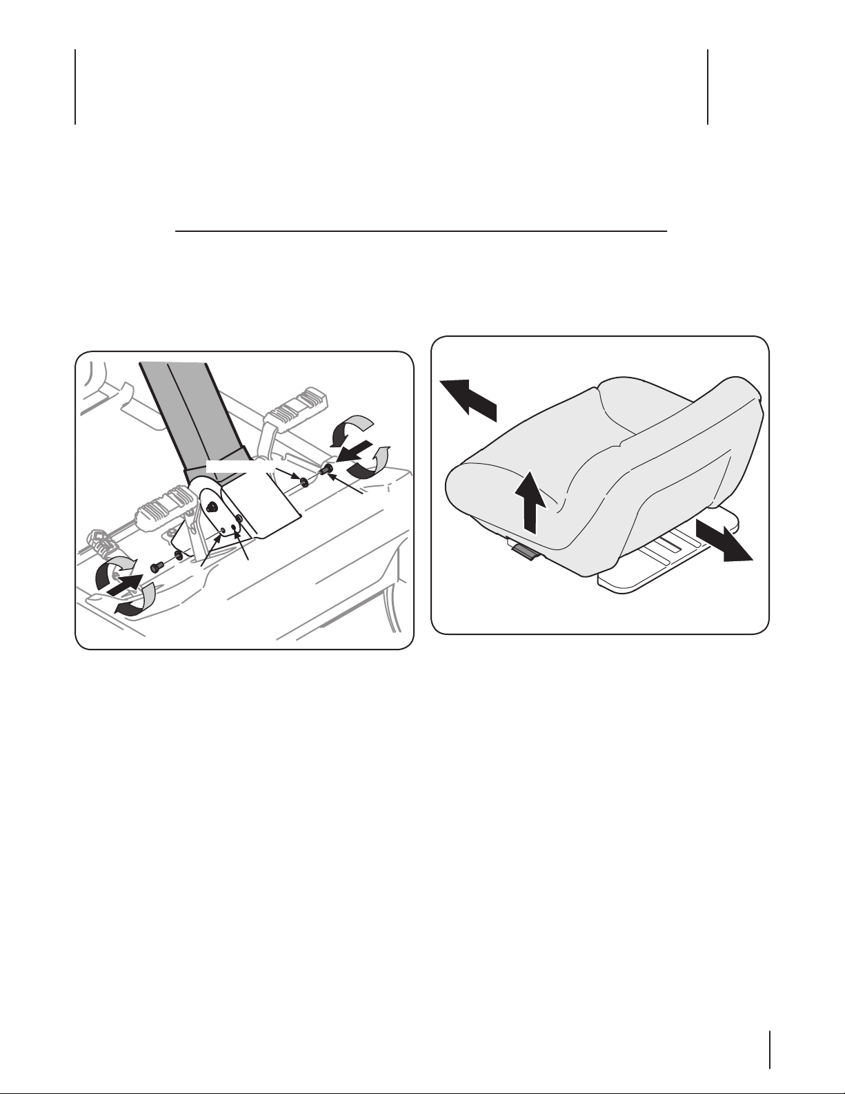
Steering Wheel Column
Place the steering column in one of the two desired positions (high
or low) and secure in place with the hex screws and flat washers.
See Figure 3-1.
Figure 3-1
Adjusting the Seat
To adjust the position of the seat, lift the seat adjustment lever
up. Slide the seat forward or rearward to the desired position;
then release the adjustment lever. Make sure seat is locked into
position before operating the rider. See Figure 3-2.
Figure 3-2
NOTE: In order to have the seat tilted up, the seat must be
positioned all the way to the rear. Caution should be used to
avoid damage to the battery cover when tilting the seat forward.
9
Page 10
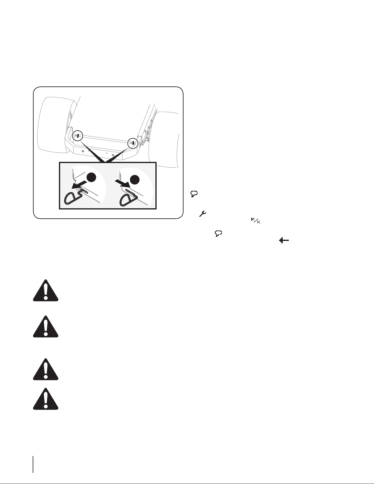
Manually Moving the Rider
a
b
1. Engage the transmission bypass rods, one on each side of
the rider, to move the rider manually without starting it.
The transmission bypass rods are located on the rear of the
rider, just inside each rear wheel. Engage the bypass rods
by pulling each one out (a) and to the right (b) to lock it into
place. See Figure 3-3.
Figure 3-3
2. Disengage the bypass rods by reversing steps a & b after
moving the rider. See Figure 3-3.
3. Remove the deck wash system nozzle adapter from the
manual bag and store for future use.
Refer to the manual packed with your battery charger for
information and instructions on charging the batteries. Refer to
the Controls & Features section of this manual for the location of
the charging port on the rider.
NOTE: Use only the battery charger provided with this rider.
NOTE: The batteries should be fully charged before the initial use.
NOTE: Never charge a frozen battery.
NOTE: It is recommended that the rider be charged once every
month during off-season storage.
NOTE: Always disconnect battery charger (or extension cord,
if used) from the electrical outlet first, then disconnect battery
charger from the charging port.
NOTE: It is recommended that the batteries be fully charged
after each use. Storing batteries in a discharged state could
reduce future performance.
NOTE: It is recommended that the uit be plugged in at all times
when not in use.
LCD Display
The language and measurements can be changed while the
rider is on by pressing the “BLADE NORMAL” button below the
icon. To set the language, press the “BLADE NORMAL” button
until the desired langauge is displayed. To change the language
and measurement, press the “SYSTEM SETTINGS” button below
the icon. When the menu comes up, press the “BLADE
BOOST” button below the icon to change the measurements,
to change the language press the “BLADE NORMAL” button
below the icon. To go back to the home screen, press the
“SYSTEM SETTINGS” button below the icon.
Charging the Batteries
CALIFORNIA PROPOSITION 65 WARNING!
Battery posts, terminals, and related accessories
contain lead and lead compounds, chemicals known
to the State of California to cause cancer and
reproductive harm. Wash hands after handling.
WARNING: The batteries contain corrosive fluid
and toxic material — HANDLE WITH CARE. Keep
away from children. Do not puncture, disassemble,
mutilate, or incinerate. Explosive gases could be
vented during charging or discharging. Charge in a
well ventilated area, away from sources of ignition.
WARNING! Recharge only with the charger
provided with this rider. A charger that is not
suitable for this machine may damage the batteries
or create the risk of fire.
WARNING! Do not charge or operate the rider in the
rain or in wet conditions.
NOTE: The batteries in your rider are not expected to last for
the life of your rider. Rechargeable batteries degrade with time
and use. The batteries may eventually need to be replaced. To
have the batteries replaced, contact your authorized Cub Cadet
Service Dealer.
10 Section 3— Se t-Up
Page 11

Controls & Features
Key Switch
(Batteries)
Forward
Drive Pedal
Reverse Drive Pedal
Deck Lift Handle
Deck Height
Index Bracket
Steering Wheel
Brake
Pedal
Cup Holder
Storage Tray
Blade Start/
Stop Knob
Cargo Box & Cargo Net
Charging Port Cover/
Charging Port
Reverse Caution
Mode Button
Headlight
Button
LCD Screen
Cruise Control
Button
Start/Stop
Button
Seat Adjustment Lever
Dash
Function
Buttons
LH Console
RH Console
P
A
R
K
B
R
A
K
E
4
NOTE: References to LEFT, RIGHT, FRONT, and REAR indicate that
position on the rider when facing forward while seated in the
operator’s seat.
Deck Height Index Bracket
The deck height index bracket consists of eight index
notches located on the front of the RH console. Each
notch corresponds to a ⁄” change in the cutting height
ranging from 1-⁄” (position 1) to 4” (position 8).
Deck Lift Handle
The deck lift handle is located on the front of the RH console,
it is used to either raise or lower the mower deck to the
desired cutting position.
Pull the handle out of the index bracket to lower or raise the
cutting deck to the desired position. Move the lift handle to
the right until fully engaged in the index bracket.
Park Brake Lock (Not Shown)
The park brake lock is located at the base of the
steering column. It is used to engage the parking brake
when the rider is at rest. Refer to the Operation section
of this manual for detailed instructions regarding the
park brake lock.
NOTE: The park brake lock must be set if the operator
leaves the seat.
WARNING! Never leave a powered machine on
and unattended. Always disengage Blade Start/Stop
Knob, stop the rider, set parking brake and remove
key to prevent unintended starting.
11
Page 12

Forward Drive Pedal
The forward drive pedal is located on the front, right
side of the running board. Press the forward drive
pedal forward to travel forward. Ground speed is also
controlled with the forward drive pedal. The further
forward the pedal is moved, the faster the rider will
travel. The pedal will return to its original position
when released.
Reverse Pedal
The reverse drive pedal is located on the front, right
side of the running board. Ground speed is also
controlled with the reverse drive pedal. The further
downward the pedal is moved, the faster the rider
will travel. The pedal will return to its original position
when released.
Brake Pedal
The brake pedal is located on the left
front side of the running board. The
brake pedal can be used for sudden
stops or setting the parking brake.
NOTE: The brake pedal must be fully depressed to activate the
safety interlock switch when starting the rider.
Transmission Bypass Rods
The transmission bypass rods (one for each transmission) are
located under the rider on the back of each transmission inside
the rear wheels.
When engaged, the two rods allow the rider to be pushed a short
distance by hand. Refer to the Assembly & Set-Up section for
instructions on using the bypass feature.
Cup Holder
The cup holder is located on the RH console to the right of the
key switch.
Storage Tray
The storage tray is located at the rear of the RH console next to
the cup holder.
Key Switch (Batteries)
The key switch is located on the RH console and sends power
to the ignition control module when the switch is in the ON
position. The rider cannot be started unless the key switch is in
the ON position. Turning the switch to the OFF position turns
the rider off and stops the flow of power to the vehicle control
module.
Blade Start/Stop Knob
The blade start/stop knob is located on the RH
console next to the key switch.
The blade start/stop knob operates the electric
motors on the deck. Pull the knob upward to
engage the blades, or push the knob downward
to disengage the blades.
NOTE: The blade start/stop knob must
be in the OFF position when starting the
rider.
Cruise Control On/Off Button
CRUISE CONTROL ON / OFF
Pressing the cruise control on/off button while the rider is in
motion allows the rider to remain at a constant ground speed
without applying pressure to the forward drive pedal. The cruise
control can be disengaged by pressing either the cruise control
button, the brake pedal, the forward drive pedal or the reverse
drive pedal. Refer to the Operation section of this manual for
detailed instructions regarding the cruise control feature.
NOTE: Cruise control will not engage at the rider’s fastest ground
speed. If the operator should attempt to do so, the rider will
automatically decelerate to the fastest optimal mowing ground
speed.
NOTE: Cruise control will not engage in reverse.
Seat Adjustment Lever
The seat adjustment lever is located below the left side of the
seat. Refer to the Assembly & Set-Up section for instructions on
adjusting the seat position.
Charging Port
The charging port is located on the LH console. To access the
charging port, lift up on the charging port cover.
12 Sectio n 4— controlS & FeatureS
Page 13

Reverse Caution Mode Button (RCM)
Headlight Button
REVERSE CAUTION MODE
NO
CHILDREN
AROUND
CAUTION: Prior to operating the rider, refer to the
Operation section of this manual for detailed
instructions regarding operating the rider in
REVERSE CAUTION MODE .
The reverse caution mode button is located on the left side
of the dash. When activated the indicator light is illuminated.
The reverse caution mode allows the rider to be operated in
reverse with the blades engaged. Refer to the Operation section
of this manual for more information on operating the rider in the
reverse caution mode.
NOTE: Mowing in reverse is not recommended.
WARNING! Use extreme caution while operating
the rider in the REVERSE CAUTION MODE. Always
look down and behind before and while backing. Do
not operate the rider when children or others are
around. Stop the rider immediately if someone
enters the area.
REVERSE CAUTION
MODE ON LIGHT
Rider Start/Stop Button
LIGHTS ON / OFF
The headlight button is located on the right side of the dash and
is used to turn the headlight on or off.
LCD Screen
The LCD display is located in the center of the dash and is used to
provide instructions, warnings and information about your rider
and its systems. See page 14 for a breakdown of the icons you
will see on your screen and an explanation of what these icons
mean.
RIDER
ON L
IGHT
RIDER START / STOP
The rider start/stop button is located on the right side of
the dash and is used to start and stop the rider when the key
switch is in the ON position. When the rider start/stop button is
activated the indicator light is illuminated.
Function Buttons
BLADE
BOOST
The function buttons are on the rider’s dash and located below
the LCD Screen. The function buttons are used to navigate
through the rider’s menu screens and change settings.
BLADE
NORMAL
SYSTEM
SETTINGS
Cargo Box & Cargo Net
The cargo box is located on the rear of the rider and could be
used for storage. The cargo net is used to secure the items in the
cargo box.
WARNING! Do not permit anyone to ride or stand
on the cargo box. They could fall off and be seriously
injured.
CAUTION: The storage area has a maximum
weight capacity of 20 pounds. Additional weight
may cause damage to the rider or affect the stability
of the tractor.
13Section 4 — control S & FeatureS
Page 14

LCD Symbols
This page depicts and describes LCD symbols that may appear on the LCD panel. Read, understand, and follow all instructions on the tractor
before attempting to assemble and operate. Refer to the Operation section of this manual for more information on these symbols.
Symbol Description
Unplug the charger.
Charger is unplugged
When this icon is flashing on the LCD
screen the battery level is being measured
by the electrical system.
Sit in the operator’s seat.
Operator is in the seat.
Push Blade Start/Stop Knob Down/Off.
Blade Start/Stop Knob is Down/Off.
Symbol Description
Start/stop button has been pressed.
Tractor speed.
Blades engaged indicator.
Blade boost indicator.
Cruise control indicator.
Battery level indicator.
Power usage indicator.
Remove foot from the forward/reverse
pedal.
Foot is off the forward/reverse drive
pedal.
Place foot on brake pedal.
Foot is on brake pedal.
Press the start/stop button
Reverse Caution Mode is activated.
Pressing the function button beneath
this icon brings up a screen that shows
run time, deck run time, odometer,
allows language change (English/French/
Spanish), and unit change (km/mph).
Pressing the function button beneath this
icon allows the user to switch between
English, French and Spanish.
14 Sectio n 4— controlS & FeatureS
Page 15

Operation
Forward Drive Pedal
Reverse Drive Pedal
Park Brake Lock
Brake Pedal
5
General Safety
• RECEIVE INSTRUCTION — Entirely read this operator’s
• Do not charge or operate the rider in the rain or in wet
• Do not mow on wet grass. Reduced traction could cause
• Before starting the rider or beginning operation, be familiar
• Keep all shields in place. Keep away from moving parts.
• NO RIDERS! Keep all people and pets a safe distance away.
• DO NOT direct the mower discharge at people.
• Avoid slopes where possible. Never operate on slopes greater
• Before leaving the operator’s seat disengage the blades
• Avoid any sudden movements of the steering wheel when
• Be careful when operating near roadways. Stop the rider
• Do not operate the rider with the mower deck removed.
• Avoid operation on traction surfaces that are unstable; use
• Slow down before turning and come to a complete stop
• Do not stop the rider or park the rider over combustible
Before Operating Your Rider
• Before you operate the rider, study this manual carefully
• Check the tire inflation pressures. See the Maintenance &
• Adjust the seat for operator’s maximum comfort, visibility
manual. Learn to operate this machine SAFELY. Do not risk
INJURY or DEATH. Allow only those who have become
competent in its usage to operate this rider.
areas.
sliding.
with the controls. The operator should be in the operator’s
seat. The blades must be disengaged and the parking
brake engaged.
Look behind and down to both sides of the rider before
and while backing up.
than 15°. Slopes with a greater incline present dangerous
operating conditions. Rider may tip or roll over.
and engage the parking brake, shut off the rider and
remove the key. Wait for all movement to stop before
servicing or cleaning.
starting and stopping. Keep a firm grip on the steering wheel.
motion and wait for vehicles to pass before operating
along the road.
Removal of the deck will change the balance of the rider,
and could contribute to a rider tipover/rollover.
extreme caution if the surface is slippery.
before any zero turn maneuver.
materials such as dry grass, leaves, debris, etc.
to familiarize yourself with the operation of all the
instruments and controls. It has been prepared to help you
operate and maintain your rider efficiently.
Adjustments section of this manual for more information
on the tires.
and for maintaining complete control of the rider. See the
Set-Up section of this manual for more information on
adjusting the seat.
Operating the Parking Brake
To set the parking brake (Refer to Figure 5-1):
Figure 5-1
1. Press down on the brake pedal .
2. While holding the brake pedal down, press down on the
park brake lock and release the brake pedal .
To release the parking brake (Refer to Figure 5-1):
1. Press down on the brake pedal , the park brake lock or
either one of the drive pedals.
Safety Interlock System
This rider is equipped with a safety interlock system for the
protection of the operator. If the interlock system should ever
malfunction, do not operate the rider. Contact your Cub Cadet
Service dealer.
• The safety interlock system prevents the rider from
starting unless the parking brake is set, and the blades are
disengaged.
• The rider will automatically shut off if the operator leaves
the seat.
• To test the Safety Interlock System, leave the rider running,
engage the park brake latch, and lift up from the seat for
a few seconds. If the rider shuts off, the system is working
correctly. If the rider does not shut off, do not operate the
rider. Contact your authorized Cub Cadet Service Dealer.
WARNING! Do not operate the rider if the
interlock system is malfunctioning. This system was
designed for your safety and protection.
15
Page 16

Starting the Rider
WARNING! This rider is equipped with a safety
interlock system designed for the protection of the
operator. Do not operate the rider if any part of the
system is malfunctioning. Periodically check the
function of the interlock system for proper operation.
WARNING! For personal safety, the operator must
be sitting in the seat when starting the rider.
To start the rider follow the steps below:
NOTE: The LCD display will also walk you through the steps
necessary to start the rider. When each task is completed the
icon will change to a darkened icon on the display and advance
to the next step.
NOTE: If the task has already been completed the LCD display will
skip that step and automatically move on to the next, i.e. if you
are already in the operator’s seat when you turn the key switch
on the step will not appear on the screen.
1. Unplug the charger. See Figure 5-2.
3. Make sure the blade start/stop knob in the DISENGAGED
position. See Figure 5-4.
Figure 5-4
4. Insert the key into the key switch and turn it to the ON
position.
NOTE: At this point you can change the language or
measurements as instructed in the Set-Up section.
5. If your foot is on the forward/reverse drive pedal, remove it.
See Figure 5-5.
Figure 5-2
2. Sit in the rider seat. See Figure 5-3.
Figure 5-3
Figure 5-5
6. Place foot on the brake pedal. See Figure 5-6.
Figure 5-6
Section 5— operation16
Page 17

7. To start the rider, press and hold the start/stop button. See
Fig ure 5-7.
Figure 5-7
8. When the rider starts the screen will display the power
usage indicator, battery level indicator, rider speed and
“POWER ON” will display on the screen. See Figure 5-8.
Figure 5-8
NOTE: When the rider is powered on the the battery
icon will flash until the battery level is measured by the
electrical system. The battery level will not be accurate
until the battery icon stops flashing.
Stopping the Rider
1. Disengage the blades by pressing the blade start/stop knob
down.
2. Engage the parking brake lock as instructed in page 15.
3. Turn the key switch to the OFF position and remove the key.
NOTE: Always remove the key from the key switch to prevent
accidental starting or battery discharge if the equipment is left
unattended.
WARNING! In case of a system fault or a complete
loss of battery power the tractor can free-wheel.
Depress the brake pedal to maintain control and
stop the unit. Restart the tractor. If the problem
persists, contact your service dealer.
NOTE: If the rider stops, the blades stop or the speed of the rider
is reduced and an error message flashes on your LCD screen,
refer to the Troubleshooting section of this manual.
1. Release the parking brake.
2. To travel FORWARD, slowly press the forward drive pedal
forward until the desired speed is achieved. See Figure 5-1.
3. To travel in reverse, look down and behind the rider and
slowly push down on the reverse drive pedal with the
ball of your foot (NOT your heel) until the desired speed is
achieved. See Figure 5-1.
NOTE: The blades will stop when traveling in reverse
unless the Reverse Caution Mode is activated. See Reverse
Caution Mode (RCM) on page 19 for information.
CAUTION: Do NOT attempt to change the direction
of travel when the rider is in motion. Always bring the
rider to a complete stop before moving the rider from
forward to reverse or vice versa.
WARNING! Do not leave the seat of the rider
without first disengaging the blades and setting the
parking brake. If leaving the rider unattended, also
turn the rider off and remove the key.
4. To slow down the rider, slowly release the forward or reverse
drive pedal . To stop the rider, press down on the brake pedal
or remove your foot from the forward or reverse drive
pedal . To lock the parking brake, refer to page 15.
5. To use the cruise control:
a. Press down on the forward drive pedal .
b. While maintaining the desired speed press the cruise
control button on the dash then release the
forward drive pedal to activate the cruise control.
When the cruise control is active the cruise control
icon will appear on the bottom left of your
screen. See Figure 5-9.
Driving The Rider
WARNING! Avoid sudden starts, excessive speed
and sudden stops.
WARNING! Never reach through the steering
wheel to press any buttons on the dash while the
rider is in motion.
CAUTION: When driving the rider immediately
after full charge (i.e. just after removing it from the
charger) the rider will operate at lower speeds and
start slowly even when the drive pedals are fully
depressed. The mower will also “pulse brake” when
traveling downhill during this period. This rapid
decelaration is designed to avoid damaging the
electrical system. This is normal and will stop once
the rider has been in use.
Figure 5-9
NOTE: Cruise control will not engage in reverse.
5. To release the cruise control; press the brake pedal , the
forward drive pedal , the reverse drive pedal or the
cruise control button .
Section 5 — oper ation 17
Page 18

Driving On Slopes
Refer to the SLOPE GAUGE on page 8 to help determine slopes
where you may operate the rider safely.
WARNING! Do not mow on inclines with a slope in
excess of 15 degrees (a rise of approximately 2-⁄
feet every 10 feet). The rider could overturn and
cause serious injury.
CAUTION: When driving the rider immediately
after full charge (i.e. just after removing it from the
charger) the rider will operate at lower speeds and
start slowly even when the drive pedals are fully
depressed. The mower will also “pulse brake” when
traveling downhill during this period. This rapid
decelaration is designed to avoid damaging the
electrical system. This is normal and will stop once
the rider has been in use.
• Mow across slopes, not up and down.
• Exercise extreme caution when changing direction on slopes.
• Watch for holes, ruts, bumps, rocks, or other hidden
objects. Uneven terrain could overturn the machine. Tall
grass can hide obstacles.
• Do not turn on slopes unless necessary. If it is necessary to turn
on a slope, turn slowly uphill and use extra care while turning.
Turning up a slope greatly increases the chance of a rollover.
• Avoid stopping when driving up a slope. If it is necessary to
stop while driving up a slope, start up smoothly and carefully
to reduce the possibility of flipping the rider over backward.
Engaging/Disengaging the Blades
To engage/disengage the blades:
1. To engage the blades pull up on the blade start/stop knob.
2. To disengage the blades push down on the blade start/stop
knob.
first two laps, reverse the direction to throw the discharge
to the outside for the balance of cutting. This will give a
better appearance to the lawn.
• Do NOT attempt to mow heavy brush, weeds or extremely tall
grass. Your rider is designed to mow lawns, NOT clear brush.
• Keep the blades sharp and replace or sharpen when worn.
Dull blades will reduce battery run time.
Blades Boost/Blades Normal Function
1. The rider is equipped with a blades boost function/optimal
load that increases the speed of the blade rotation. To engage
the blade boost, press the “BLADE BOOST” button below the
blade boost icon on the LCD display. When the blade boost is
active, the icon will darken. See Figure 5-10.
Figure 5-10
2. To return the mower to the blades normal function/light load,
press the “BLADE NORMAL” button under the blades normal
icon. When the blades normal is active the icon will darken.
See Figure 5-11.
Mowing
WARNING! Never reach through the steering
wheel to press any buttons on the LCD display while
the rider is in motion.
WARNING! To help avoid blade contact or a thrown
object injury, keep bystanders, helpers, children and
pets at least 75 feet from the machine while it is in
operation. Stop machine if anyone enters the area.
WARNING! Plan your mowing pattern to avoid
discharge of materials toward roads, sidewalks,
bystanders and the like. Also, avoid discharging
material against a wall or obstruction which may
cause discharged material to ricochet back toward
the operator.
• Mow across slopes, not up and down. If mowing a slope, start
at bottom and work upward to ensure turns are made uphill.
• Do not mow at high ground speed, especially if a mulch kit
(available separately) is installed.
• Do not cut the grass too short. Short grass is prone to weed
growth and yellows quickly in dry weather.
• For best results it is recommended that the first two laps be
cut with the discharge thrown towards the center. After the
Figure 5-11
3. Mowing with the blade boost on will decrease mowing time
and will increase the battery drain. But it may be the optimal
blade speed for the best cut depending on conditions.
4. In early season and/or thick grass conditions the blades should
always be in blade boost function to ensure a quality cut.
Section 5— operation18
Page 19

Using the Mower Deck
WARNING! Make certain the area to be mowed is
free of debris, sticks, stones, wire or other objects
that can be thrown by the rotating blades.
NOTE: When the battery charge gets too low, the blades will
automatically disengage and stop. The LCD screen will flash low
battery. When this situation occurs, the rider should be plugged
into the charger as soon as possible.
NOTE: If the rider stops, the blades stop or the speed of the rider
is reduced and an error message flashes on your LCD screen,
refer to the Troubleshooting section of this manual.
1. Place the mower deck in the desired height by moving the
deck lift lever to the left, then place it in the notch best
suited for your application.
2. Engage the blades by pulling up on the blade start/stop knob
and select either the blades boost or blades normal function
depending on the conditions.
3. On the first pass pick a point on the opposite side of the
area to be mowed and maintain a straight line towards that
point to help achieve a quality cut.
4. Slowly press the forward drive pedal forward until the
desired speed is achieved, and keep the rider headed
directly toward the alignment point.
NOTE: The speed of the rider will affect the quality of the
mower cut. Mowing at full speed will adversely affect the cut
quality. Control the ground speed with the drive pedals.
5. When approaching the other end of the strip, slow down
or stop before turning. A U-turn is recommended unless a
pivot or zero turn is required.
6. Align the mower with an edge of the mowed strip and
overlap approximately 3”.
7. Direct the rider on each subsequent strip to align with a
previously cut strip.
8. To prevent rutting or grooving of the turf, if possible, change
the direction that the strips are mowed by approximately 45°
for the next and each subsequent mowing.
WARNING! Be careful when crossing gravel paths
or driveways. Disengage the blades and raise the
deck to the highest position before crossing.
NOTE: When stopping the rider for any reason while on a
grass surface, always engage the parking brake, shut the
rider off and remove the key.
Reverse Caution Mode (RCM)
The Reverse Caution Mode allows the rider to be operated in
reverse with the blades engaged.
NOTE: Mowing in reverse is not recommended.
WARNING! Use extreme caution while operating
the rider in the Reverse Caution Mode (RCM). Always
look down and behind before and while backing. Do
not operate the rider when children or others are
around. Stop the rider immediately if someone
enters the area.
To use the Reverse Caution Mode (RCM):
NOTE: The operator MUST be seated in the rider seat.
1. Start the rider as previously instructed on page 16.
2. Press the Reverse Caution Mode (RCM) button on the
left side of the dash.
3. Once the RCM button is pressed a warning statement
will display on the LCD screen asking for confirmation of
activating the RCM. To continue in RCM press the “BLADE
BOOST” button below the “Yes” icon, to cancel RCM press
the “SYSTEM SETTINGS” button below the “No” icon. See
Figure 5-12.
Figure 5-12
4. Once activated (indicator light on and warning symbol
on the bottom, right of the LCD screen), the rider can be
driven in reverse with the cutting blades engaged. See
Figure 5-13.
Figure 5-13
5. Always look down and behind before and while backing to
make sure no children are around.
NOTE: The Reverse Caution Mode will remain activated
until the Reverse Caution Mode button is pressed, the rider
is shut off or the operator leaves the seat.
Section 5 — oper ation 19
Page 20

Maintenance & Adjustments
Maintenance Schedule
6
Prior to Use
Lube Front Caster Wheels and Wheel Spindles
Lube Pedal Pivot Points
Grease Front Castings
Check Blades
Charge Battery
Check Hardware
NOTE: The electrical components on this rider are not
serviceable. Please contact an authorized Cub Cadet service
dealer for any service needs.
WARNING! Have your rider serviced by qualified
service personnel using only identical replacement
parts. This will ensure that the safety of the rider is
maintained.
P P
P P
P
Maintenance
WARNING! Before performing any maintenance or
repairs, stop the rider, disengage blades, set parking
brake and remove key to prevent unintended starting
of the blades or movement of the rider.
Battery Storage
1. The batteries should be stored with a full charge. Discharged
batteries can freeze faster than charged batteries in cold
temperatures.
2. The battery charger should remain connected to the charging
port on the rider when not in use.
3. If keeping the charger connected during off-season storage is
not possible, the batteries should be fully charged once every
month.
NOTE: It will take approximately 16 hours to fully charge the
batteries. Leaving the batteries connected to the charger
for more than 16 hours will not damage the batteries.
4. Batteries should not be kept in a discharged state. Permanent
damage to the batteries can occur.
5. Fully charge batteries once a month during off-season storage.
6. Fully recharge the batteries before returning to service.
Every
10 Hours
Every
25 Hours
Every
50 Hours
Prior to O-Season
Storage
P P
P P
P
Charging the Batteries
CALIFORNIA PROPOSITION 65 WARNING!
Battery posts, terminals, and related accessories
contain lead and lead compounds, chemicals known
to the State of California to cause cancer and
reproductive harm. Wash hands after handling.
WARNING: The battery contains corrosive fluid
and toxic material — HANDLE WITH CARE. Keep
away from children. Do not puncture, disassemble,
mutilate, or incinerate. Explosive gases could be
vented during charging or discharging. Use in a well
ventilated area, away from sources of ignition.
WARNING! Recharge only with the charger
specified by the manufacturer. A charger that is
suitable for one type of battery pack may create a
risk of fire when used with another battery pack.
WARNING! Do not charge or operate the rider in the
rain or in wet locations.
NOTE: The batteries in your rider are not expected to last for
the life of your rider. Rechargeable batteries degrade with time
and use. The batteries may eventually need to be replaced. To
have the batteries replaced, contact your authorized Cub Cadet
Service Dealer.
NOTE: Replace batteries if battery capacity drops below 50% of
initial capacity
NOTE: Using old or faulty batteries could cause a system fault
that results in loss of power
20
Page 21

Refer to the manual packed with your battery charger for
Charging Port Cover
Charging Port
Charging Cord
information and instructions on charging the batteries. Lift the
charging port cover up and insert the charging cord into the
charging port located in the left console. See Figure 6-1.
Figure 6-1
Battery Charging Tips
• Use only the battery charger provided with this rider.
• The batteries should be fully charged before the each use.
• It is recommended that the rider be charged once every
month during off-season storage.
• It will take approximately 16 hours to fully charge the
batteries. Leaving the batteries connected to the charger
for more than 16 hours will not damage the batteries.
• The batteries do not develop a memory and do not need to
be fully discharged before recharging.
• Always disconnect battery charger (or extension cord, if
used) from the electrical outlet first, then disconnect the
charging cord from the charging port.
• It is recommended that the rider be charged after reach
use. Storing batteries in a discharged state could reduce
future performance.
3. Lubricate all lubrication points.
NOTE: Use of a pressure washer or garden hose is not
recommended to clean your rider. This may cause
damage to electrical components and bearings. The use
of excessive water will result in shortened life and reduce
serviceability.
Removing The Rider From Storage
1. Fully charge the batteries and inflate the tires to the
recommended pressures.
2. Drive the rider without a load to make certain all the rider
systems are functioning properly.
Cleaning the Rider
A brush, damp sponge or rag should be used to clean the rider.
NOTE: Do not spray water into the battery compartment when
cleaning the rider. Doing so can cause serious damage to the
riders electrical system.
NOTE: To clean the battery cover, the seat must be positioned all
the way back to be tilted up to access the area under the seat.
Cleaning the Deck
NOTE: The deck is not removable.
Your rider’s deck is equipped with a water port on its surface as
part of its deck wash system.
Use the Smart Jet™ to rinse grass clippings from the deck’s
underside to prevent the buildup of corrosive chemicals.
Complete the following steps AFTER EACH MOWING:
1. Drive the rider to a level, clear spot on your lawn, close
enough for your garden hose to reach.
CAUTION: Make certain the rider’s discharge chute
is directed AWAY from your house, garage, parked
cars, etc.
2. Stop the rider, disengage the blades, set the parking brake
and turn the key switch to the OFF position.
3. Thread the hose coupler (packaged with your rider’s
Operator’s Manual) onto the end of your garden hose.
Rider Storage
NOTE: Store rider indoors in a dry place and out of the reach of
children.
If your rider is not going to be operated for an extended period
of time (thirty days to approximately six months), the rider should
be prepared for storage. Store the rider in a dry and protected
location. If stored outside, cover the rider completely to protect
it from the elements. The procedures outlined below should be
performed whenever the rider is placed in off-season storage.
1. Clean the entire rider thoroughly.
2. Fully charge the batteries and recharge the batteries every
30 days when in storage.
Section 6 — Mainte nance & adjuStMentS
21
Page 22

Grease Fittings
4. Attach the hose coupler to the water port on the left of
your deck surface. See Figure 6-2.
CAUTION: Be certain the hose is clear of the deck
and no part of the hose is under the deck before
starting the rider.
Lubrication
WARNING! Before lubricating, repairing, or
inspecting, always stop the rider, disengage blades,
set parking brake and remove key to prevent
unintended starting.
Front Wheels
Each of the front wheel spindles and rims is equipped with a grease
fitting. See Figure 6-3. Lubricate with a No. 2 multi-purpose grease
applied with a grease gun after every 25 hours of rider operation.
Figure 6-2
5. Turn the water on.
6. While sitting in the operator’s position, start the rider as
instructed beginning on page 16..
7. Engage the blades.
8. Remain in the operator’s position with the cutting deck
engaged for a minimum of two minutes, allowing the
underside of the cutting deck to thoroughly rinse.
9. Disengage the blades.
10. Turn the key switch to the OFF position to turn off the rider.
11. Turn the water off and detach the hose coupler from the
water port on your deck’s surface.
12. After cleaning your deck with the Smart Jet™ system, return
to the operator’s position, start the rider and engage the
blades. Keep the cutting deck running for a minimum of
two minutes, allowing the underside of the cutting deck to
thoroughly dry.
Figure 6-3
Tires
Refer to the tire sidewall for exact tire manufacturer’s
recommended or maximum psi. Do not overinflate. Uneven tire
pressure could cause the cutting deck to mow unevenly.
WARNING! Never exceed the maximum inflation
pressure shown on the sidewall of the tire.
22
Section 6— Maintenance & adjuStMentS
Page 23

Adjustments
Adjustment
Gear
Hex Bolt
Lock Nut
Front Deck Lift Rod
Clockwise to raise,
counterclockwise to lower
NOTE: Check the rider’s tire pressure before performing any deck
leveling adjustments. Refer to Tires for information regarding tire
pressure.
WARNING! Shut the rider off, remove the key and
engage the parking brake before making
adjustments. Protect your hands by using heavy
gloves when handling the blades.
Leveling the Deck (Side to Side)
NOTE: Check the rider’s tire pressure before performing any deck
leveling adjustments. Refer to Tires for information regarding tire
pressure. Always level the deck side to side before front to rear.
If the cutting deck appears to be mowing unevenly, a side to side
adjustment can be performed. Adjust if necessary as follows:
1. With the rider parked on a firm, level surface, place the deck
lift handle in a middle mowing position and rotate both
outside blades so that they are in-line (side-to-side) with the
rider.
2. Measure the distance from the outside of the left blade
tip to the ground and the distance from the outside of the
right blade tip to the ground. Both measurements taken
should be equal. If they’re not, proceed to the next step.
3. Loosen, but do NOT remove, the hex bolt on the rear left
deck hanger link. See Figure 6-4.
Leveling the Deck (Front To Rear)
NOTE: Check the rider’s tire pressure before performing any
deck leveling adjustments. Refer to Tires section on page 22 for
information regarding tire pressure. Always level the deck side to
side before front to rear.
The front of the deck should be ⁄ ⁄” lower than the rear of the
deck. Adjust if necessary as follows:
1. Park the rider on a firm, level surface and place the deck lift
handle in a middle position.
2. Rotate the blade nearest the discharge chute so that it is in
line (front-to-back) with the rider.
3. Measure the distance from the front of the blade tip to the
ground and the rear of the blade tip to the ground. The
front measurement taken should be ⁄⁄” less than the rear
measurement.
4. Determine the approximate distance necessary for proper
adjustment and proceed, if necessary.
5. Using a wrench, raise or lower the front of deck by turning
lock nut on the front deck lift rod. See Figure 6-5.
Figure 6-4
NOTE: The rear right deck hanger link is not adjustable and
is used to help adjust the other hanger links.
4. Using a wrench, raise or lower the left side of the deck by
turning the adjustment gear. See Figure 6-4.
The deck is properly leveled when both blade tip measurements
are equal. Retighten the hex bolt on the rear left deck hanger
bracket when proper adjustment is achieved.
Figure 6-5
6. The deck is properly leveled when the front tip of the blade
is ⁄-⁄” lower than the rear tip. Retighten the hex bolt
on the left and right rear deck hanger links when proper
adjustment is achieved.
Section 6 — Mainte nance & adjuStMentS
23
Page 24

Adjusting the Deck Wheels
Gauge Wheel
Shoulder Bolt
Flange
Lock Nut
Gauge Wheel
Bracket
Move the rider on a firm and level surface, preferably pavement,
and proceed as follows
1. Place the deck lift handle in the desired mowing height
setting.
2. Check the deck wheels for contact or excessive clearance
with the surface below. The deck wheels should have
between ¼-½” clearance above the ground.
3. If the deck wheels have excessive clearance or contact with
the surface, adjust as follows:
a. Raise the deck lift handle to its highest setting.
b. Remove the front and rear deck wheels by removing
the lock nuts and shoulder bolts which secure them
to the deck. See Figure 6-6.
Figure 6-6
c. Place the deck lift handle in the desired mowing
height setting.
d. Reinsert the shoulder bolts (with each gauge wheel)
into the index hole that leaves approximately
⁄-½” between the bottom of the wheel and the
pavement.
Parking Brake Adjustment
If the rider does not come to a complete stop when the park/
brake pedal is completely engaged, or if the rider’s rear wheels
can roll with the parking brake applied (transmission bypass rods
engaged), the brake is in need of adjustment. See your Cub Cadet
dealer to have the brake properly adjusted.
24
Section 6— Maintenance & adjuStMentS
Page 25

Service
Blade Adapter
Blade
Blade Bell
Support
Hex Screw
7
WARNING! Have your rider serviced by qualified
service personnel using only identical replacement
parts. This will ensure that the safety of the rider is
maintained.
NOTE: The electrical components on this rider are not user
serviceable. Please contact an authorized Cub Cadet service
dealer for any service needs.
Blade Care
WARNING: When removing the cutting blade for
sharpening or replacement, protect your hands with
a pair of heavy gloves or use a heavy rag to hold the
blade.
WARNING! After striking a foreign object, stop the
rider. Thoroughly inspect the machine for any
damage. Repair the damage before starting and
operating.
Periodically inspect the blade adapter for cracks, especially if you
strike a foreign object. Replace when necessary. Follow the steps
below for blade service.
1. The deck on the rider should not be removed. To access the
blades the rider can be placed on a lift, driven on ramps or
placed on jack stands.
WARNING: Be sure the rider is secured and the
parking brake is set when removing the blades.
4. Balance the blade on a round shaft screwdriver to check.
Remove metal from the heavy side until it balances evenly.
When sharpening the blade, follow the original angle of
the blade and cutting edge. Grind or file each cutting edge
equally to keep the blade balanced.
WARNING: An unbalanced blade will cause
excessive vibration when rotating at high speeds. It
may cause damage to the motor or the mounting
hardware which could cause personal injury.
5. Visually inspect the blade adapter for any damages or
cracks.
6. Lubricate the inner surface of the blade adapter with light
oil. Slide the blade adapter onto the deck motor spindle.
Place the blade on the adapter such that the side of the
blade marked “Bottom” (or with part number) faces the
ground when the rider is in the operating position. Make
sure that the blade is aligned and seated on the blade
adapter flanges.
6. Place blade bell support on the blade. Align notches on the
blade bell support with small holes in blade.
7. Replace hex bolt and tighten torque to 450 in. lbs. min., 600
in. lbs. max.
To ensure safe operation of your rider, periodically check the
blade bolt for correct torque.
2. Remove the hex screw and the blade bell support which
3. Remove blade and adapter from the deck motor spindle
holds the blade and the blade adapter to the deck motor.
See Figure 7-1.
Figure 7-1
See Figure 7-1.
25
Page 26

Troubleshooting
Problem Cause Remedy
8
Excessive vibration 1. Damaged or bent cutting blade.
1. Cutting blade loose or unbalanced.
Uneven cut 3. Uneven tire pressure.
4. Deck not leveled properly.
5. Dull blade.
Mower will not mulch grass
(If Equipped w/Mulching Kit)
Tractor Stopped or will not
start
1. Blade speed too low.
2. Excessively high grass.
3. Wet grass.
4. Dull blade.
1. Service.
2. Left hub fault.
3. Right hub fault.
4. Drive sensor fault.
5. Over-voltage
6. Pre-charge failure.
7. Left hub communication failure.
8. Right hub communication failure.
9. Left deck communication failure.
10. Right deck communication failure.
11. Contactor tips welded closed.
12. Self-test failure.
13. Contactor seat switch failure.
14. Battery charger plugged in.
1. Replace blade.
2. Tighten blade or remove and balance.
1. Check tire pressure in all four tires.
2. Perform side-to-side deck adjustment.
3. Sharpen or replace blade.
1. Turn blade boost on.
2. Mow once at a high cutting height, then
mow again at desired height or make a
narrower cutting swath.
3. Do not mulch when grass is wet.
4. Sharpen or replace blade.
1. Shut off and restart tractor. If problem
persists contact qualified service personnel.
2. Shut off and restart tractor. If problem
persists contact qualified service personnel.
3. Shut off and restart tractor. If problem
persists contact qualified service personnel.
4. Shut off and restart tractor. If problem
persists contact qualified service personnel.
5. Shut off and restart tractor. If problem
persists contact qualified service personnel.
6. Shut off and restart tractor. If problem
persists contact qualified service personnel.
7. Shut off and restart tractor. If problem
persists contact qualified service personnel.
8. Shut off and restart tractor. If problem
persists contact qualified service personnel.
9. Shut off and restart tractor. If problem
persists contact qualified service personnel.
10. Shut off and restart tractor. If problem
persists contact qualified service personnel.
11. Shut off and restart tractor. If problem
persists contact qualified service personnel.
12. Shut off and restart tractor. If problem
persists contact qualified service personnel.
13. Check to see if seat switch is plugged in. Shut
off and restart tractor. If problem persists
contact qualified service personnel.
14. Unplug charger and return to the start-up
prompt.
26
Page 27

Problem Cause Remedy
The blades do not rotate/
blades stopped
The blades do not rotate in
reverse
Reduced speed
1. Left deck fault.
2. Right deck fault.
3. Overload
4. Low battery.
5. Steering sensor fault.
6. Brake sensor fault.
1. Blades stopped
1. Low Battery
2. Overload
3. Steering sensor fault.
4. Brake sensor fault.
1. Shut off and restart tractor. If problem
persists contact qualified service personnel.
2. Shut off and restart tractor. If problem
persists contact qualified service personnel.
3. Allow deck motors to cool. Raise deck height.
4. Return home, plug into charger.
5. Shut off and restart tractor. If problem
persists contact qualified service personnel.
6. Shut off and restart tractor. If problem
persists contact qualified service personnel.
1. Restart blades. Make sure Reverse Caution
Mode is activated.
1. Charge the battery as instructed in the
battery charger manual.
2. Raise deck.
3. Shut off and restart tractor. If problem
persists contact qualified service personnel.
4. Shut off and restart tractor. If problem
persists contact qualified service personnel.
27Section 8 — troubleShooting
Page 28

Replacement Parts
9
NOTE: Many parts on this tractor are not customer serviceable. Please contact an authorized Cub Cadet dealer for any service needs
for parts not listed below.
Component Part Number and Description
942-04403 Blade
734-04155 Deck Wheel
625-05000 Ignition Key
631-04288 Chute Deflector
634-04293 Wheel Assembly
634-04711 Caster Wheel Assembly
727-04402 Cargo Net
725-05350 Charger
28
725-05395 * Battery
* — This part can only be ordered and installed by an
Authorized Cub Cadet Dealer.
Page 29

Attachments & Accessories
Part No. Part
19A70029100 Mulch Kit
19A70033100 Hitch Kit
10
29
Page 30

Notes
11
30
Page 31

31Section 11 — noteS
Page 32

CUB CADET LLC
MANUFACTURER’S LIMITED WARRANTY
FOR ELECTRIC RESIDENTIAL ZEROTURN “ERZT” MOWERS
IMPORTANT: To obtain warranty coverage owner must present
an original proof of purchase and applicable maintenance records
to the servicing dealer. Please see the operator’s manual for
information on required maintenance and service intervals.
The limited warranty set forth below is given by Cub Cadet LLC
with respect to new merchandise purchased or leased and used in
the United States and/or its territories and possessions, and by MTD
Products Limited with respect to new merchandise purchased or
leased and used in Canada and/or its territories and possessions
(either entity respectively, “Cub Cadet”).
This warranty is in addition to any applicable emissions warranty
provided with your product.
Cub Cadet warrants this entire product (excluding its Normal Wear
Parts, and Attachments as described below) against defects in
material and workmanship for a period of three (3) years or one
hundred twenty (120) operation hours, whichever comes first,
commencing on the date of original retail purchase or lease and
will, at its option, repair or replace, free of charge, any part found to
be defective in materials or workmanship.
Normal Wear Parts are warranted to be free from defects in material
and workmanship for a period of thirty (30) days from the date of
original purchase or lease. Normal wear parts include, but are not
limited to items such as: blades, blade adapters, grass bags, rider
deck wheels, seats, and tires.
Batteries are warranted to maintain at least half of their original
charge holding capacity for the duration of this warranty. If any
original equipment battery loses more than half of its charge
holding capacity as determined by your Cub Cadet dealer or
a generally accepted and reliable battery capacitance testing
method it shall be considered defective for purposes of the
warranty, Cub Cadet will replace any such defective battery free of
charge under the terms of this warranty. Any replacement battery
will be warranted for the remainder of the original warranty period
or 12 months from installation whichever is longer.
Attachments — Cub Cadet warrants attachments for this product
against defects in material and workmanship for a period of one
(1) year, commencing on the date of the attachment’s original
purchase or lease. Attachments include, but are not limited to items
such as: grass collectors and mulch kits.
This limited warranty shall only apply if this product has been
operated and maintained in accordance with the Operator’s
Manual furnished with the product, and has not been subject to
misuse, abuse, neglect, accident, improper maintenance, alteration,
vandalism, theft, fire, water, or damage because of other peril or
natural disaster. Damage resulting from the installation or use of
any part, accessory or attachment not approved by Cub Cadet
for use with the product(s) covered by this manual will void your
warranty as to any resulting damage. In addition, Cub Cadet may
deny warranty coverage if the hour meter, or any part thereof, is
altered, modified, disconnected or otherwise tampered with.
HOW TO OBTAIN SERVICE: Warranty service is available, WITH
PROOF OF PURCHASE AND APPLICABLE MAINTENANCE RECORDS,
through your local authorized service dealer. To locate the dealer in
your area:
Cub Cadet LLC, P.O. BOX 361131 CLEVELAND, OHIO 44136-0019, Phone: 1-877-282-8684
MTD Products Limited, Kitchener, ON N2G 4J1, Phone: 1-800-668-1238
051034 Rev. A
In the U.S.A.:
Check your Yellow Pages, or contact Cub Cadet LLC at P.O. Box
361131, Cleveland, Ohio 44136-0019, call 1-877-282- 8684 or log on
to our website at www.cubcadet.com.
In Canada:
Contact MTD Products Limited, Kitchener, ON N2G 4J1, call
1-800-668-1238 or log on to our website at www.mtdcanada.com.
Without limiting the foregoing, this limited warranty does not
provide coverage in the following cases:
a. Routine maintenance items such as lubricants, filters, blade
sharpening, tune-ups, brake adjustments, clutch adjustments,
deck adjustments, and normal deterioration of the exterior
finish due to use or exposure.
b. Service completed by someone other than an authorized
service dealer.
c. Cub Cadet does not extend any warranty for products sold
or exported outside of the United States and/or Canada, and
their respective possessions and territories, except those
sold through Cub Cadet’s authorized channels of export
distribution.
d. Replacement parts and\or accessories that are not genuine
Cub Cadet parts.
e. Transportation charges and service calls.
There are no implied warranties, including without limitation
any implied warranty of merchantability or fitness for a
particular purpose. No warranties shall apply after the
applicable period of express written warranty above. No other
express warranties beyond those mentioned above, given by
any person or entity, including a dealer or retailer, with respect
to any product, shall bind Cub Cadet. The exclusive remedy is
repair or replacement of the product as set forth above. The
terms of this warranty provide the sole and exclusive remedy
arising from the sale and/or lease of the products covered
hereby. Cub Cadet shall not be liable for any incidental or
consequential loss or damage including, without limitation,
expenses incurred for substitute or replacement lawn care
services or for rental expenses to temporarily replace a
warranted product.
Some jurisdictions do not allow the exclusion or limitation of
incidental or consequential damages, or limitations on how long an
implied warranty lasts, so the above exclusions or limitations may
not apply to you.
In no event shall recovery of any kind be greater than the amount
of the purchase price of the product sold. Alteration of safety
features of the product shall voidthis warranty. You assume the
risk and liability for loss, damage, or injury to you and your property
and/or to others and their property arising out of the misuse or
inability to use the product.
This limited warranty shall not extend to anyone other than the
original purchaser or to the person for whom it was purchased as a
gift.
HOW LOCAL LAWS RELATE TO THIS WARRANTY: This limited
warranty gives you specific legal rights, and you may also have
other rights that vary in different jurisdictions.
 Loading...