

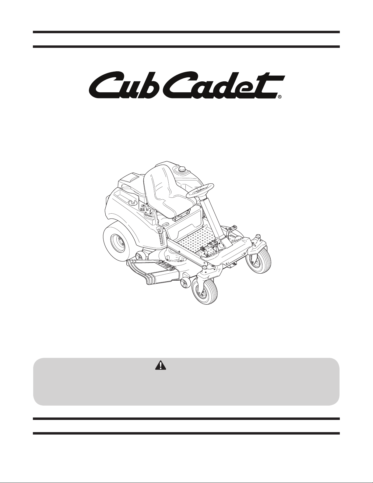
Cub Cadet RZT S Series Operator's Manual
Safe Operation Practices • Set-Up • Operation • Maintenance • Service • Troubleshooting • Warranty
OperatOr’s Manual
RZT S Series Tractor
WARNING
READ AND FOLLOW ALL SAFETY RULES AND INSTRUCTIONS IN THIS MANUAL
BEFORE ATTEMPTING TO OPERATE THIS MACHINE.
FAILURE TO COMPLY WITH THESE INSTRUCTIONS MAY RESULT IN PERSONAL INJURY.
P. O. Box 1386 KITCHENER, ONTARIO, CANADA N2G 4J1
Printed In USA
769-09496A
9.9.14

To The Owner
Thank You
Please read this entire manual prior to operating the equipment.
It instructs you how to safely and easily set up, operate and
maintain your machine. Please be sure that you, and any other
persons who will operate the machine, carefully follow the
recommended safety practices at all times. Failure to do so could
result in personal injury or property damage.
All information in this manual is relative to the most recent
product information available at the time of printing. Review
this manual frequently to familiarize yourself with the machine,
its features and operation. Please be aware that this Operator’s
Manual may cover a range of product specifications for
various models. Characteristics and features discussed and/or
illustrated in this manual may not be applicable to all models.
The manufacturer reserves the right to change product
specifications, designs and equipment without notice and
without incurring obligation.
Table of Contents
1
This product has met the rigid safety standards of the Outdoor
Power Equipment Institute and an independent testing
laboratory. If you have any problems or questions concerning the
machine, phone your local authorized service dealer.
Throughout this manual, all references to right and left side of the
machine are observed from the operating position.
The engine manufacturer is responsible for all engine-related
issues with regards to performance, power-rating, specifications,
warranty and service. Please refer to the engine manufacturer’s
Owner’s/Operator’s Manual, packed separately with your
machine, for more information.
Safe Operation Practices ........................................ 3
Assembly & Set Up ................................................... 9
Controls & Features ................................................12
Operation ................................................................15
Maintenance & Adjustment .................................19
Troubleshooting .................................................... 30
Accessories ..............................................................31
Replacement Parts ................................................ 32
Emissions Control Warranty Statement .............. 34
Warranty ................................................................ 36
Service .................................................................... 24
Record Product Information
Before setting up and operating your new equipment, please
locate the model plate on the equipment and record the
information in the provided area to the right. You can locate the
model plate by looking beneath the seat. This information will be
necessary, should you seek technical support from an authorized
service dealer.
Model NuMber
Serial NuMber
Customer Support
If you have difficulty assembling this product or have any questions regarding the controls, operation, or maintenance of
this machine, you can seek help from the experts. Choose from the options below:
◊ Visit our web at www.cubcadet.ca
◊ Locate your nearest dealer at: 1-800-668-1238
◊ Contact Cub Cadet, 97 Kent Ave., Kitchener, ON N2G 4J1 Phone: 1-800-668-1238 or
LES DISTRIBUTIONS RVI LIMITÉE, 29,55, Jean-Baptiste Deschamps, Lachine, Quebec H8T 1C5 Phone: 1-800-361-5770
2

Important Safe Operation Practices
WARNING! This symbol points out important safety instructions which, if not followed,
could endanger the personal safety and/or property of yourself and others. Read and follow
all instructions in this manual before attempting to operate this machine. Failure to comply
with these instructions may result in personal injury.
When you see this symbol. HEED ITS WARNING!
CALIFORNIA PROPOSITION 65
WARNING! Engine Exhaust, some of its constituents, and certain vehicle components
contain or emit chemicals known to State of California to cause cancer and birth defects
or other reproductive harm.
WARNING! Battery posts, terminals, and related accessories contain lead and lead
compounds, chemicals known to the State of California to cause cancer and reproductive
harm. Wash hands after handling
DANGER! This machine was built to be operated according to the safe operation practices in
this manual. As with any type of power equipment, carelessness or error on the part of the
operator can result in serious injury. This machine is capable of amputating hands and feet
and throwing objects. Failure to observe the following safety instructions could result in
serious injury or death.
2
General Operation
1. Read, understand, and follow all instructions on the
machine and in the manual(s) before attempting to
assemble and operate. Keep this manual in a safe place for
future and regular reference and for ordering replacement
parts.
2. Be familiar with all controls and their proper operation.
Know how to stop the machine and disengage them
quickly.
3. Never allow children under 14 years of age to operate this
machine. Children 14 and over should read and understand
the instructions and safe operation practices in this manual
and on the machine and should be trained and supervised
by an adult.
4. Never allow adults to operate this machine without proper
instruction.
5. To help avoid blade contact or a thrown object injury,
keep bystanders, helpers, children and pets at least 75 feet
from the machine while it is in operation. Stop machine if
anyone enters the area.
6. Thoroughly inspect the area where the equipment is to be
used. Remove all stones, sticks, wire, bones, toys, and other
foreign objects which could be picked up and thrown by
the blade(s). Thrown objects can cause serious personal
injury.
7. Plan your mowing pattern to avoid discharge of material
toward roads, sidewalks, bystanders and the like. Also,
avoid discharging material against a wall or obstruction
which may cause discharged material to ricochet back
toward the operator.
8. Always wear safety glasses or safety goggles during
operation and while performing an adjustment or repair
to protect your eyes. Thrown objects which ricochet can
cause serious injury to the eyes.
9. Wear sturdy, rough-soled work shoes and close-fitting
slacks and shirts. Loose fitting clothes and jewelry can be
caught in movable parts. Never operate this machine in
bare feet or sandals.
10. Be aware of the mower and attachment discharge direction
and do not point it at anyone. Do not operate the mower
without the discharge cover or entire grass catcher in its
proper place.
11. Do not put hands or feet near rotating parts or under the
cutting deck. Contact with the blade(s) can amputate
hands and feet.
3

12. A missing or damaged discharge cover can cause blade
contact or thrown object injuries.
13. Stop the blade(s) when crossing gravel drives, walks, or
roads and while not cutting grass.
14. Watch for traffic when operating near or crossing
roadways. This machine is not intended for use on any
public roadway.
15. Do not operate the machine while under the influence of
alcohol or drugs.
16. Mow only in daylight or good artificial light.
17. Never carry passengers.
18. Back up slowly. Always look down and behind before and
while backing to avoid a back-over accident. Be aware
and pay attention to the safety system function that
stops power to the blades when driving in reverse. If not
fuctioning properly, contact an authorized dealer for safety
system inspection and repair.
19. Slow down before turning. Operate the machine smoothly.
Avoid erratic operation and excessive speed.
20. Disengage blade(s), set parking brake, stop engine and wait
until the blade(s) come to a complete stop before removing
grass catcher, emptying grass, unclogging chute, removing
any grass or debris, or making any adjustments.
21. Never leave a running machine unattended. Always turn off
blade(s), place drive control levers in neutral, set parking
brake, stop engine and remove key before dismounting.
22. Use extra care when loading or unloading the machine into
a trailer or truck. This machine should not be driven up or
down ramp(s), because the machine could tip over, causing
serious personal injury. The machine must be pushed
manually on ramp(s) to load or unload properly.
23. Muffler and engine become hot and can cause a burn. Do
not touch.
24. Check overhead clearances carefully before driving under
low hanging tree branches, wires, door openings etc.,
where the operator may be struck or pulled from the
machine, which could result in serious injury.
25. Disengage all attachment clutches, set the parking brake to
the ‘ON’ position.
26. Your machine is designed to cut normal residential grass of
a height no more than 10”. Do not attempt to mow through
unusually tall, dry grass (e.g., pasture) or piles of dry leaves.
Dry grass or leaves may contact the engine exhaust and/
or build up on the mower deck presenting a potential fire
hazard.
27. Use only accessories and attachments approved for this
machine by the machine manufacturer. Read, understand
and follow all instructions provided with the approved
accessory or attachment.
28. Data indicates that operators, age 60 years and above, are
involved in a large percentage of riding mower-related
injuries. These operators should evaluate their ability
to operate the riding mower safely enough to protect
themselves and others from serious injury.
29. If situations occur which are not covered in this manual, use
care and good judgment. Contact your customer service
representative for assistance.
Slope Operation
Slopes are a major factor related to loss of control and tip-over
accidents which can result in severe injury or death. All slopes
require extra caution. If you cannot back up the slope or if you
feel uneasy on it, do not mow it.
For your safety, use the slope gauge included as part of this
manual to measure slopes before operating this machine on
a sloped or hilly area. If the slope is greater than 15 degrees as
shown on the slope gauge, do not operate this machine on that
area or serious injury could result.
Do:
1. Mow across slopes, not up and down. Exercise extreme
caution when changing direction on slopes.
2. Watch for holes, ruts, bumps, rocks, or other hidden
objects. Uneven terrain could overturn the machine. Tall
grass can hide obstacles.
3. Use slow speed. Choose a low enough speed so that you
will not have to stop while on the slope. Avoid starting
or stopping on a slope. If the tires are unable to maintain
traction, disengage the blades and proceed slowly and
carefully straight down the slope.
4. Follow the manufacturer’s recommendations for wheel
weights or counterweights to improve stability.
5. Use extra care with grass catchers or other attachments.
These can change the stability of the machine.
6. Keep all movement on the slopes slow and gradual. Do
not make sudden changes in speed or direction. Rapid
acceleration or deceleration could cause the front of the
machine to lift and rapidly flip over backwards, which
could cause serious injury.
Do Not:
1. Do not turn on slopes unless necessary; then turn slowly
uphill and use extra care while turning.
2. Do not mow near drop-offs, ditches or embankments. The
mower could suddenly turn over if a wheel is over the edge
of a cliff, ditch, or if an edge caves in.
3. Do not try to stabilize the machine by putting your foot on
the ground.
4. Do not use a grass catcher on steep slopes.
5. Do not mow on wet grass. Reduced traction could cause
sliding.
6. Do not tow heavy pull behind attachments (e.g. loaded
dump cart, lawn roller, etc.) on slopes greater than 5
degrees. When going down hill, the extra weight tends to
push the tractor and may cause you to lose control (e.g.
tractor may speed up, braking and steering ability are
reduced, attachment may jack-knife and cause tractor to
overturn).
4 Section 2 — important Safe operation practiceS

Children
1. Tragic accidents can occur if the operator is not alert to the
presence of children. Children are often attracted to the
machine and the mowing activity. They do not understand
the dangers. Never assume that children will remain where
you last saw them.
a. Keep children out of the mowing area and in
watchful care of a responsible adult other than the
operator.
b. Be alert and turn machine off if a child enters the
area.
c. To avoid back-over accidents, always look behind
and down for small children.
d. Never carry children, even with the blade(s) shut off.
They may fall off and be seriously injured or interfere
with safe machine operation.
e. Use extreme care when approaching blind corners,
doorways, shrubs, trees or other objects that may
block your vision of a child who may run into the
path of the machine.
f. Keep children away from hot or running engines.
They can suffer burns from a hot muffler.
g. Remove key when machine is unattended to
prevent unauthorized operation.
2. Never allow children under 14 years of age to operate this
machine. Children 14 and over should read and understand
the instructions and safe operation practices in this manual
and on the machine and should be trained and supervised
by an adult.
Towing
1. Tow only with a machine that has a hitch designed for
towing. Do not attach towed equipment except at the
hitch point.
2. Follow the manufacturers recommendation for weight
limits for towed equipment and towing on slopes.
3. Never allow children or others in or on towed equipment.
4. On slopes, the weight of the towed equipment may cause
loss of traction and loss of control.
5. The maximum weight on the hitch is 50 lbs. and the
maximum towed load is 250 lbs.
6. Never allow passengers on the towed equipment.
7. Loss of traction can occur on slopes, 5° (9 %) maximum
grade.
8. Travel slowly and allow extra distance to stop.
9. Use caution during turns to avoid jack-knifing.
10. Use extra caution when operating in reverse.
11. Do not modify or repair the hitch, replace the hitch if
damaged.
12. Travel slowly and allow extra distance to stop.
13. Do not shift to neutral and coast downhill.
Service
Safe Handling of Gasoline:
1. To avoid personal injury or property damage use extreme
care in handling gasoline. Gasoline is extremely
flammable and the vapors are explosive. Serious
personal injury can occur when gasoline is spilled on
yourself or your clothes which can ignite. Wash your skin
and change clothes immediately.
a. Use only an approved gasoline container.
b. Never fill containers inside a vehicle or on a truck
or trailer bed with a plastic liner. Always place
containers on the ground away from your vehicle
before filling.
c. When practical, remove gas-powered equipment
from the truck or trailer and refuel it on the ground.
If this is not possible, then refuel such equipment on
a trailer with a portable container, rather than from a
gasoline dispenser nozzle.
d. Keep the nozzle in contact with the rim of the fuel
tank or container opening at all times until fueling is
complete. Do not use a nozzle lock-open device.
e. Extinguish all cigarettes, cigars, pipes and other
sources of ignition.
f. Never fuel machine indoors.
g. Never remove gas cap or add fuel while the engine
is hot or running. Allow engine to cool at least two
minutes before refueling.
h. Never over fill fuel tank. Fill tank to no more than ½”
below bottom of filler neck to allow space for fuel
expansion.
i. Replace gasoline cap and tighten securely.
j. If gasoline is spilled, wipe it off the engine and
equipment. Move machine to another area. Wait 5
minutes before starting the engine.
k. To reduce fire hazards, keep machine free of grass,
leaves, or other debris build-up. Clean up oil or fuel
spillage and remove any fuel soaked debris.
l. Never store the machine or fuel container inside
where there is an open flame, spark or pilot light
as on a water heater, space heater, furnace, clothes
dryer or other gas appliances.
m. Allow a machine to cool at least five minutes before
storing.
General Service
1. Never run an engine indoors or in a poorly ventilated area.
Engine exhaust contains carbon monoxide, an odorless,
and deadly gas.
2. Before cleaning, repairing, or inspecting, make certain the
blade(s) and all moving parts have stopped. Disconnect
the spark plug wire(s) and ground against the engine to
prevent unintended starting.
5Section 2 — important Safe operation practiceS

3. Periodically check to make sure the blades come to
complete stop within approximately (5) five seconds after
operating the blade disengagement control. If the blades
do not stop within the this time frame, your machine
should be serviced professionally by an authorized dealer.
4. Regularly check the safety interlock system for proper
function, as described later in this manual. If the safety
interlock system does not function properly, have your
machine serviced professionally by an authorized dealer.
5. Check the blade(s) and engine mounting bolts at frequent
intervals for proper tightness. Also, visually inspect blade(s)
for damage (e.g., excessive wear, bent, cracked). Replace
the blade(s) with the original equipment manufacturer’s
(O.E.M.) blade(s) only, listed in this manual. “Use of parts
which do not meet the original equipment specifications
may lead to improper performance and compromise
safety!”
6. Mower blades are sharp. Wrap the blade or wear gloves,
and use extra caution when servicing them.
7. Keep all nuts, bolts, and screws tight to be sure the
equipment is in safe working condition.
8. Never tamper with the safety interlock system or other
safety devices. Check their proper operation regularly.
9. After striking a foreign object, stop the engine, disconnect
the spark plug wire(s) and ground against the engine.
Thoroughly inspect the machine for any damage. Repair
the damage before starting and operating.
10. Never attempt to make adjustments or repairs to the
machine while the engine is running.
11. Grass catcher components and the discharge cover are
subject to wear and damage which could expose moving
parts or allow objects to be thrown. For safety protection,
frequently check components and replace immediately
with original equipment manufacturer’s (O.E.M.) parts only,
listed in this manual. “Use of parts which do not meet the
original equipment specifications may lead to improper
performance and compromise safety!”
12. Do not change the engine governor settings or over-speed
the engine. The governor controls the maximum safe
operating speed of the engine.
13. Maintain or replace safety and instruction labels, as
necessary.
14. Observe proper disposal laws and regulations for gas, oil,
etc. to protect the environment.
15. According to the Consumer Products Safety Commission
(CPSC) and the U.S. Environmental Protection Agency (EPA),
this product has an Average Useful Life of seven (7) years,
or 270 hours of operation. At the end of the Average Useful
Life have the machine inspected annually by an authorized
service dealer to ensure that all mechanical and safety
systems are working properly and not worn excessively.
Failure to do so can result in accidents, injuries or death.
Do not modify engine
To avoid serious injury or death, do not modify engine in any
way. Tampering with the governor setting can lead to a runaway
engine and cause it to operate at unsafe speeds. Never tamper
with factory setting of engine governor.
Notice Regarding Emissions
Engines which are certified to comply with California and federal
EPA emission regulations for SORE (Small Off Road Equipment)
are certified to operate on regular unleaded gasoline, and
may include the following emission control systems: Engine
Modification (EM) and Three Way Catalyst (TWC) if so equipped.
Spark Arrestor
WARNING! This machine is equipped with an
internal combustion engine and should not be used
on or near any unimproved forest-covered,
brushcovered or grass-covered land unless the
engine’s exhaust system is equipped with a spark
arrester meeting applicable local or state laws (if
any).
If a spark arrestor is used, it should be maintained in effective
working order by the operator.
A spark arrestor for the muffler is available through your nearest
engine authorized service dealer.
WARNING! Your Responsibility — Restrict the use of this power machine to persons who read, understand and
follow the warnings and instructions in this manual and on the machine.
6 Section 2 — important Safe operation practiceS
SAVE THESE INSTRUCTIONS!
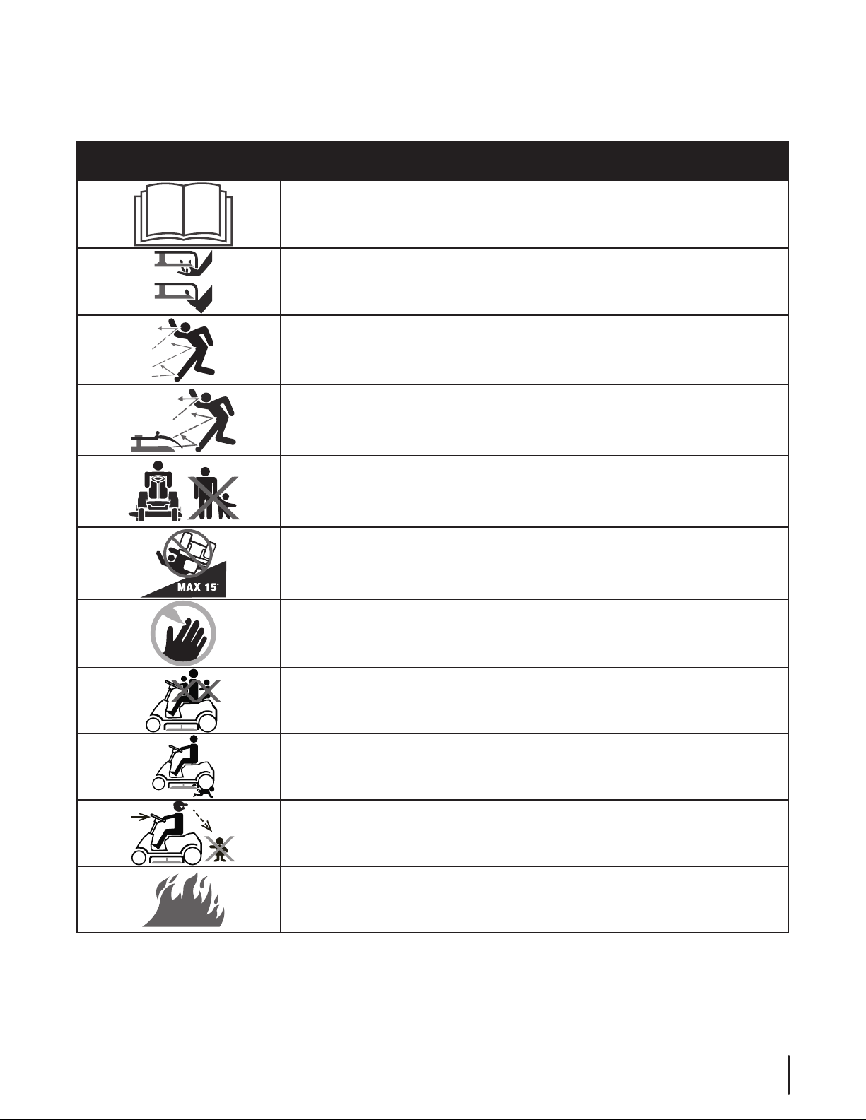
Safety Symbols
This page depicts and describes safety symbols that may appear on this product. Read, understand, and follow all instructions on the
machine before attempting to assemble and operate.
Symbol Description
READ THE OPERATOR’S MANUAL(S)
Read, understand, and follow all instructions in the manual(s) before attempting to
assemble and operate
WARNING— ROTATING BLADES
Do not put hands or feet near rotating parts or under the cutting deck. Contact with the
blade(s) can amputate hands and feet.
WARNING—THROWN OBJECTS
This machine may pick up and throw and objects which can cause serious personal injury.
WARNING—THROWN OBJECTS
This machine may pick up and throw and objects which can cause serious personal injury.
BYSTANDE RS
Keep bystanders, helpers, children and pets at least 75 feet from the machine while it is in
operation.
WARNING— SLOPE OPERATION
Do not operate this machine on a slope greater than 15 degrees.
DANGER — ROTATING BLADES
To reduce the risk of injury, keep hands and feet away. Do not operate unless discharge cover
or grass catcher is in its proper place. If damaged, replace immediately.
DANGER— ROTATING BLADES
Never carry passengers. Never carry children, even with the blades off.
DANGER— ROTATING BLADES
To avoid a back-over accident, keep children away from the machine while it is in operation.
DANGER— ROTATING BLADES
Always look down and behind before and while backing to avoid a back-over accident.
WARNING—GASOLINE IS FLAMMABLE
Allow the engine to cool at least two minutes before refueling.
7Section 2 — important Safe operation practiceS
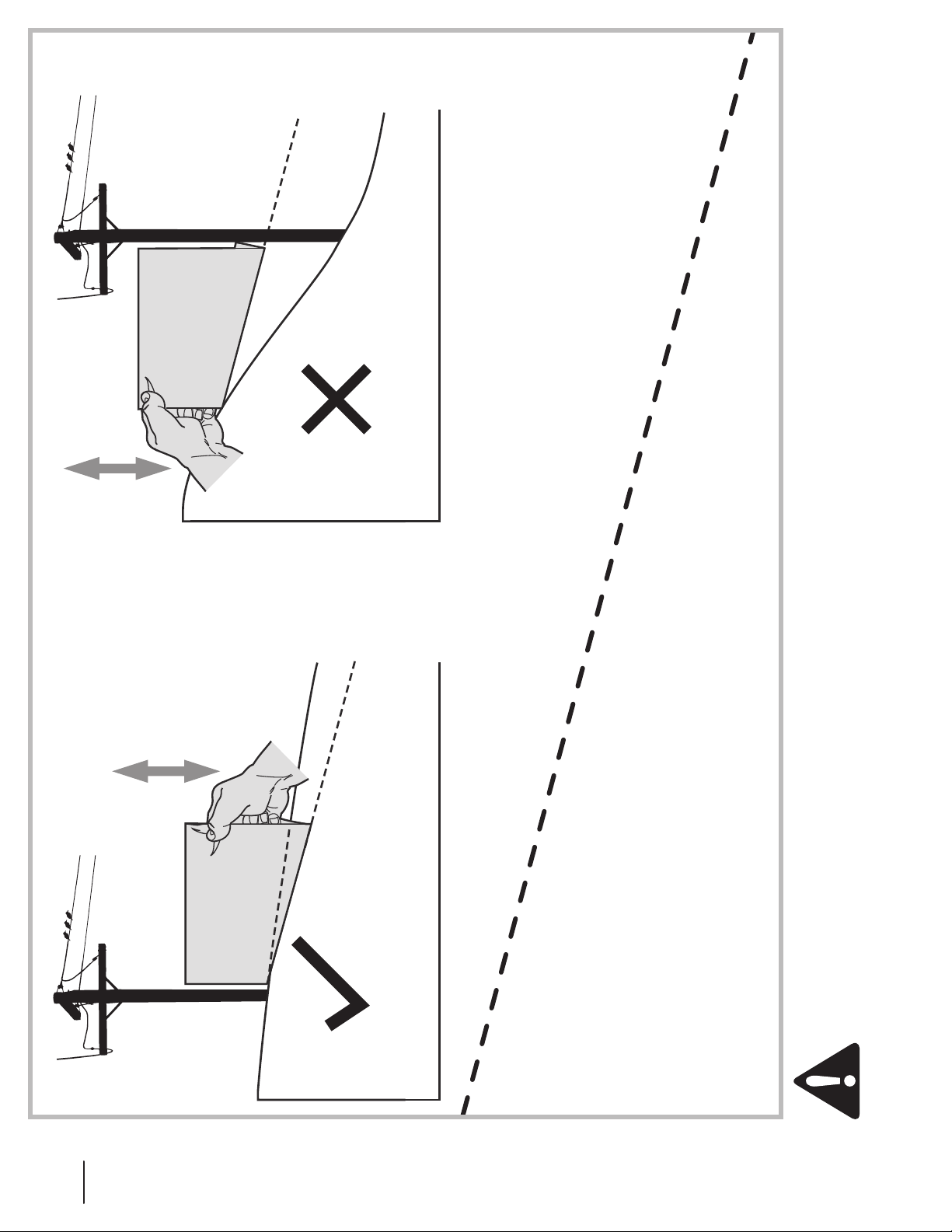
15° Slope
Figure 2Figure 1
Slope Gauge
15° Slope
(OK) (TOO STEEP)
15° dashed line
USE THIS SLOPE GAUGE TO DETERMINE
IF A SLOPE IS TOO STEEP FOR SAFE OPERATION!
To check the slope, proceed as follows:
1. Remove this page and fold along the dashed line.
2. Locate a vertical object on or behind the slope (e.g. a pole, building, fence, tree, etc.)
3. Align either side of the slope gauge with the object (See Figure 1 and Figure 2 ).
4. Adjust gauge up or down until the left corner touches the slope (See Figure 1 and Figure 2).
5. If there is a gap below the gauge, the slope is too steep for safe operation (See Figure 2 above).
Do not operate machine on slopes in excess of 15 degrees. All slopes require extra caution.
Always mow across the face of slopes, never up and down slopes.
WARNING! Slopes are a major factor related to tip-over and roll-over accidents which can result in severe injury or death.
8 Section 2 — Safe operation practi ceS
Assembly & Set-Up
a
b
Hex Screw
Flat Washer
Contents of Crate
• One Lawn Tractor • One Deck Wash Hose Coupler • One Operator’s Manual
• One Engine Operator’s Manual • Two Hex Screws and Flat Washers
3
NOTE: This Operator’s Manual covers several models. Tractor
features may vary by model. Not all features in this manual are
applicable to all tractor models and the tractor depicted may
differ from yours.
Tractor Preparation
1. Remove the upper crating material from the shipping
pallet, and cut any bands or tie straps securing the tractor
to the pallet.
2. If the deck is not in the highest mowing position (pulled
all the way back), use the deck lift handle to raise the deck
to its highest position. Refer to the Controls & Features
section for instructions on raising and lowering the deck.
3. Disengage the parking brake.
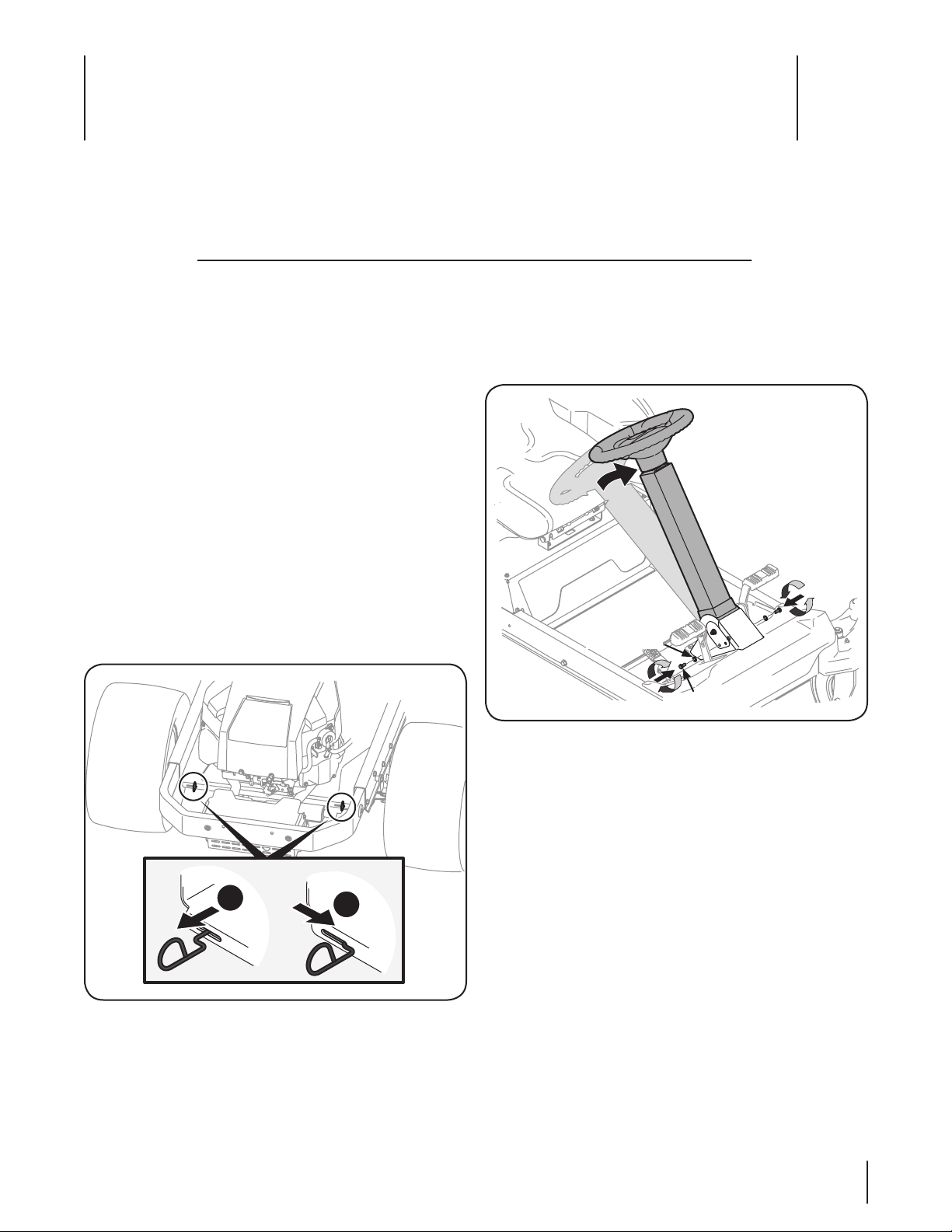
4. Engage the transmission bypass rods on each side of the
tractor; then carefully roll the tractor off the shipping
pallet. The transmission bypass rods (one for each the RH
and LH transmission) are located on the rear of the tractor,
just inside each rear wheel. Engage the bypass rods by
pulling each one out and to the right then letting it return
to lock it into place. See Figure 3-1.
Steering Wheel Column
The steering wheel column is tilted all the way back for shipping.
1. Place the steering column in one of the two positions
and secure in place with the hex screws and flat washers
packed seperately. See Figure 3-2.
Figure 3-1
5. Disengage the bypass rods after rolling the tractor off the
pallet. See Figure 3-1.
6. Remove the deck wash system nozzle adapter from the
manual bag and store for future use.
Figure 3-2
9
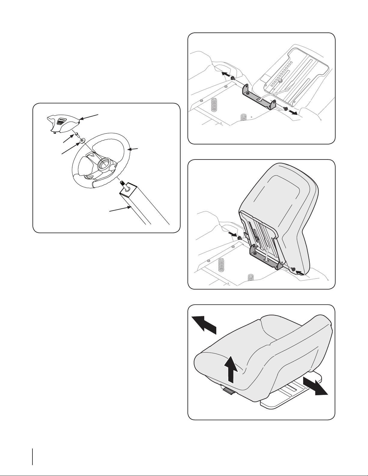
Steering Wheel
Steering Wheel Cover
Hex Screw
Steering Wheel
Steering Wheel
Column
Belleville
Washer
1. Remove the hardware for attaching the steering wheel
from beneath the steering wheel cap. Carefully pry off the
steering wheel cover to remove the hardware.
2. With the wheels of the tractor pointing straight forward,
place the steering wheel over the steering shaft.
3. Place the flat washer and belleville washer over the
steering wheel and secure with the hex screw. See Figure
3-3.
Figure 3-4
Figure 3-3
4. Place the steering wheel cover over the center of the
steering wheel and push downward until it “clicks” into
place.
Install Operator’s Seat
To install the seat proceed as follows:
NOTE: The seat is shipped with the seat switch and seat pan
attached. A second person may be needed to hold the seat.
1. Cut any straps securing the seat assembly to the tractor.
Remove any packing material.
NOTE: Be careful not to cut the wiring harness connecting the
seat and the seat switch in the bottom of the seat.
2. Remove the two shoulder screws in the seat pan as shown
in Figure 3-4.
3. Rotate the seat into position and secure the seat into place
with the previously removed shoulder screws. Be careful
not to crimp or damage the wire harness while installing
the seat. See Figure 3-5.
NOTE: Be sure to push the excess wire from the wire harness into
the seat box hole before continuing.
Adjusting the Seat
To adjust the position of the seat, lift the seat adjustment lever
up. Slide the seat forward or rearward to the desired position;
then release the adjustment lever. Make sure seat is locked into
position before operating the tractor. See Figure 3-6.
Figure 3-5
Figure 3-6
10 Section 3— ASSembly & Set-Up
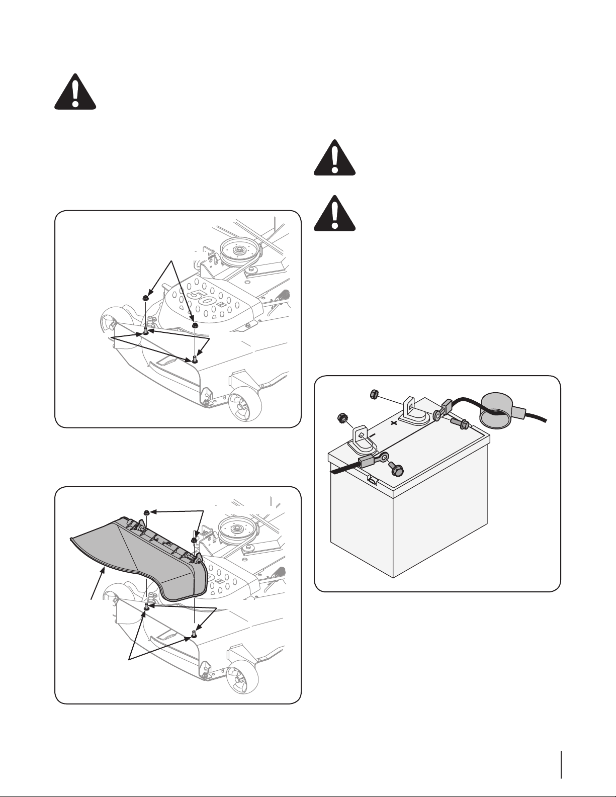
Lower Deck Discharge Chute Deflector
50” Deck
Shown
Flange Lock Nuts
Push Nuts
Carriage Bolts
Discharge
Chute
Deflector
50” Deck
Shown
Flange Lock Nuts
Push Nuts
Carriage Bolts
WARNING! Never operate the mower deck
without the chute deflector installed and in the
down position.
The discharge chute deflector must be installed before operating
the mower.
1. Remove the keys that are attached with a zip tie to the
chute bracket.
2. Remove the flange lock nuts from the deck. Do not remove
the push nuts or carriage bolts, leaving them in place will
aid in installing the chute. See Figure 3-7.
Fuel Fill-Up
Using a good grade of unleaded regular gasoline, fill the tank
(beside the engine on the left side of the mower). When the fuel
tank reaches one inch from the top of the tank, stop, DO NOT
OVERFILL. Space must be left for expansion.
Connecting the Battery Cables
CALIFORNIA PROPOSITION 65 WARNING!
Battery posts, terminals, and related accessories
contain lead and lead compounds, chemicals known
to the State of California to cause cancer and
reproductive harm. Wash hands after handling.
CAUTION: When attaching battery cables, always
connect the POSITIVE (Red) wire to its terminal first,
followed by the NEGATIVE (Black) wire.
For shipping reasons, both battery cables on your equipment
may have been left disconnected from the terminals at the
factory. To connect the battery cables, proceed as follows:
NOTE: The positive battery terminal is marked Pos. (+). The
negative battery terminal is marked Neg. (–).
NOTE: If the positive battery cable is already attached, skip ahead
to step 2.
1. Remove the plastic cover, if present, from the positive
battery terminal and attach the red cable to the positive
battery terminal (+) with the bolt and hex nut. See Figure
3-9.
Figure 3-7
3. Install the discharge chute def lector using the carriage bolts,
push nuts and flange lock nuts as shown in Figure 3-8 and
securely tighten the hardware.
Figure 3-8
Figure 3-9
2. Remove the plastic cover, if present, from the negative battery
terminal and attach the black cable to the negative battery
terminal (–) with the bolt and hex nut. See Figure 3-9.
3. Position the red rubber boot over the positive battery
terminal to help protect it from corrosion.
NOTE: If the battery is put into service after the date shown
on top/side of battery, charge the battery as instructed in the
Maintenance section your Operator’s Manual prior to operating
the tractor.
11Section 3 — ASSembly & Set-Up
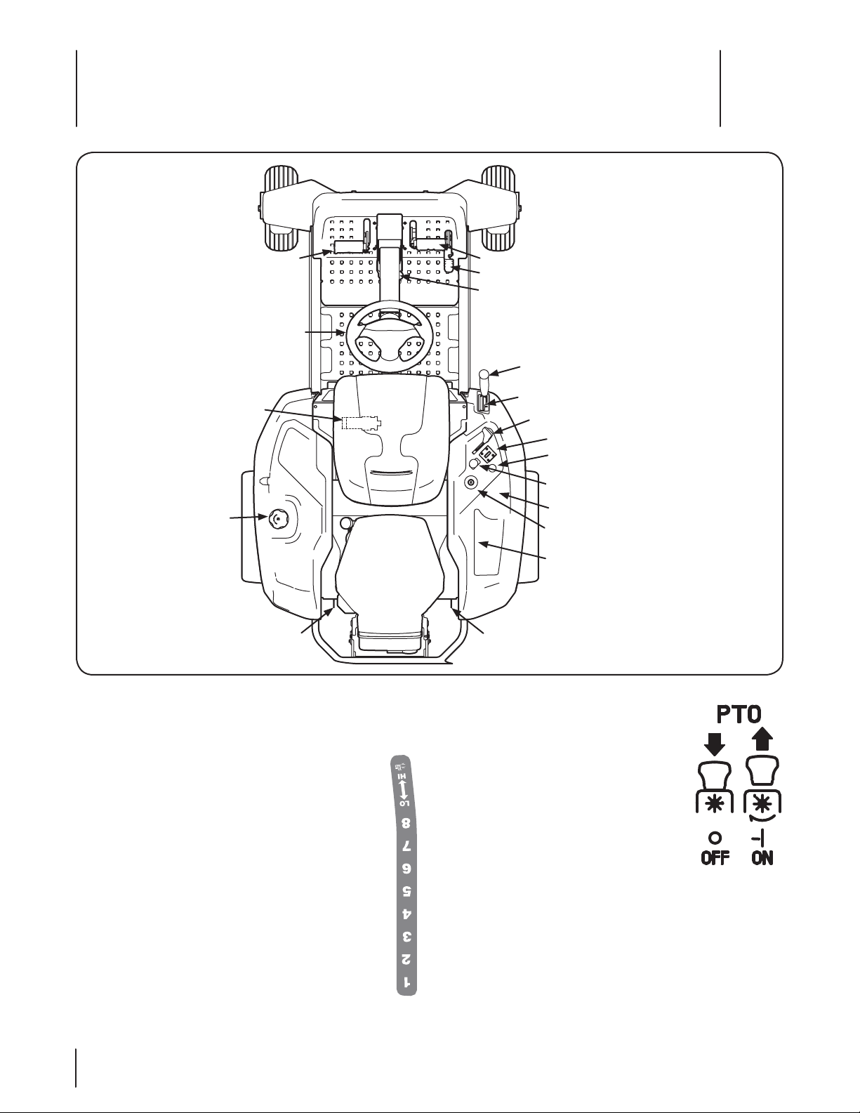
Controls & Features
4
Brake Pedal
Steering Wheel
Seat Adjustment Lever
Fuel Tank Cap
Forward Drive Pedal
Reverse Drive Pedal
Parking Brake/Cruise Control Lever
Deck Lift Handle
Deck Height Index
Throttle Control
LCD Service Minder and Hour Meter
Choke Control
PTO Knob
Cup Holder
Ignition Switch Module
Storage Tray
Transmission Bypass RodsTransmission Bypass Rods
NOTE: References to LEFT, RIGHT, FRONT, and REAR indicate that
position on the tractor when facing forward while seated in the
operator’s seat.
Deck Height Index
The deck height index consists of eight index notches
located on the front/right of the console. Each notch
corresponds to a ⁄” change in the deck height position
ranging from 1-⁄” at the lowest notch to 4” at the highest
notch.
Deck Lift Handle
The deck lift handle is located on the front/right of the
console, and is used to raise and lower the mower deck.
Pull the handle to the left out of the index notch and push
downward to lower the deck, or pull upward to raise the
deck. When the desired height is attained, move the lift
handle to the right until fully in the index notch.
12
PTO Knob
The PTO (Power Take-Off) knob is located on the
RH console to the right of the operator’s seat.
The PTO knob operates the electric PTO
clutch mounted on the bottom of the engine
crankshaft. Pull the knob upward to engage
the PTO clutch, or push the knob downward to
disengage the clutch.
The PTO knob must be in the “disengaged”
position when starting the engine.
Fuel Tank Cap
The fuel tank cap is located on the left console. Turn the fill cap
to remove. Always re-install the fuel cap tightly onto the fuel tank
after removing.
WARNING! Never fill the fuel tank when the
engine is running. If the engine is hot from recently
running, allow to cool for several minutes before
refueling. Highly flammable gasoline could splash
onto the engine and cause a fire.
Ignition Switch Module
WARNING! Never
leave a running
machine
unattended. Always
disengage PTO, set
parking brake, stop
engine and remove
key to prevent
unintended starting.
To start the engine, insert the key
into the ignition switch and turn
clockwise to the STAR T position
. Release the key into the NORMAL MOWING MODE
position once the engine has fired.
To stop the engine, turn the ignition key counterclockwise to the
STOP position .
CAUTION: Prior to operating the tractor, refer to
both Safety Interlock Switches and Starting The
Engine in the Operation section of this manual for
detailed instructions regarding the Ignition Switch
Module and operating the tractor in REVERSE
CAUTION MODE .
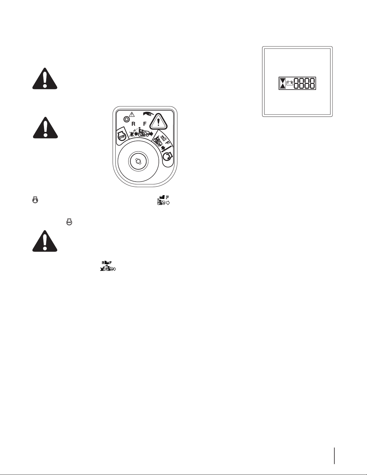
LCD Service Minder & Hour Meter
When the ignition key is rotated
out of the STOP position but
not into the START position, the
LCD Service Minder and Hour
Meter will briefly disply the
battery voltage, followed by the
tractor’s accumulated hours.
NOTE: Hours of tractor
operation are recorded any time
the ignition key is rotated out of
the STOP position, regardless of
whether the engine is started.
The LCD Service Minder will remind the operator of maintenance
intervals for changing the engine oil, air filter service, low engine
and low battery warnings.
Change Oil
The LCD will display the letters “CHG”, followed by the letters
“OIL”, followed by the letters “SOON”, then finally followed by the
meter’s accumulated time. “CHG/OIL/SOON/TIME” will alternate
on the display for 7 minutes after the meter reaches 50 hours.
This oil service minder intervall will occur every 50 hours. Before
the interval expires, change the engine oil as instructed in the
Maintenance section of this Operator’s Manual.
Low Oil
The letters “LO” followed by the letters “OIL”, then followed by
the meter’s accumulated time will indicate the tractor is low on
oil. Stop the tractor immediately and check the engine oil level as
instructed in this Owner’s Manual.
Low Battery
At startup, the battery voltage is briefly displayed then changes
to accumulated hours. The letters “LO” will display followed
by the letters “BATT” and then followedyby the meter’s
accumlulated time. “LO/BATT/TIME” is displayed on the LCD
when the voltage drops below 11.5 volts. When this occurs, the
battery is in need of a charge or the engine’s charging system
is not generating sufficient amperage. Charge the battery as
instructed in the Service section of this manual or have the
charging system checked by your local service dealer.
Air Filter Service
The letters “CLN” will display, followed by the letters “AIR”,
followed by “FILT”, then followed by the meter’s accumulated
time. “CLN/AIR/FILT/TIME” will alternate on the display for 7
minutes after the meter reachges 25 hours. This air filter service
minder time interval will be every 25 hours. On intervalls that are
common with oil service, the oil message will be diplayed first
followed by the air filter message.
13Section 4 — controlS & FeatureS
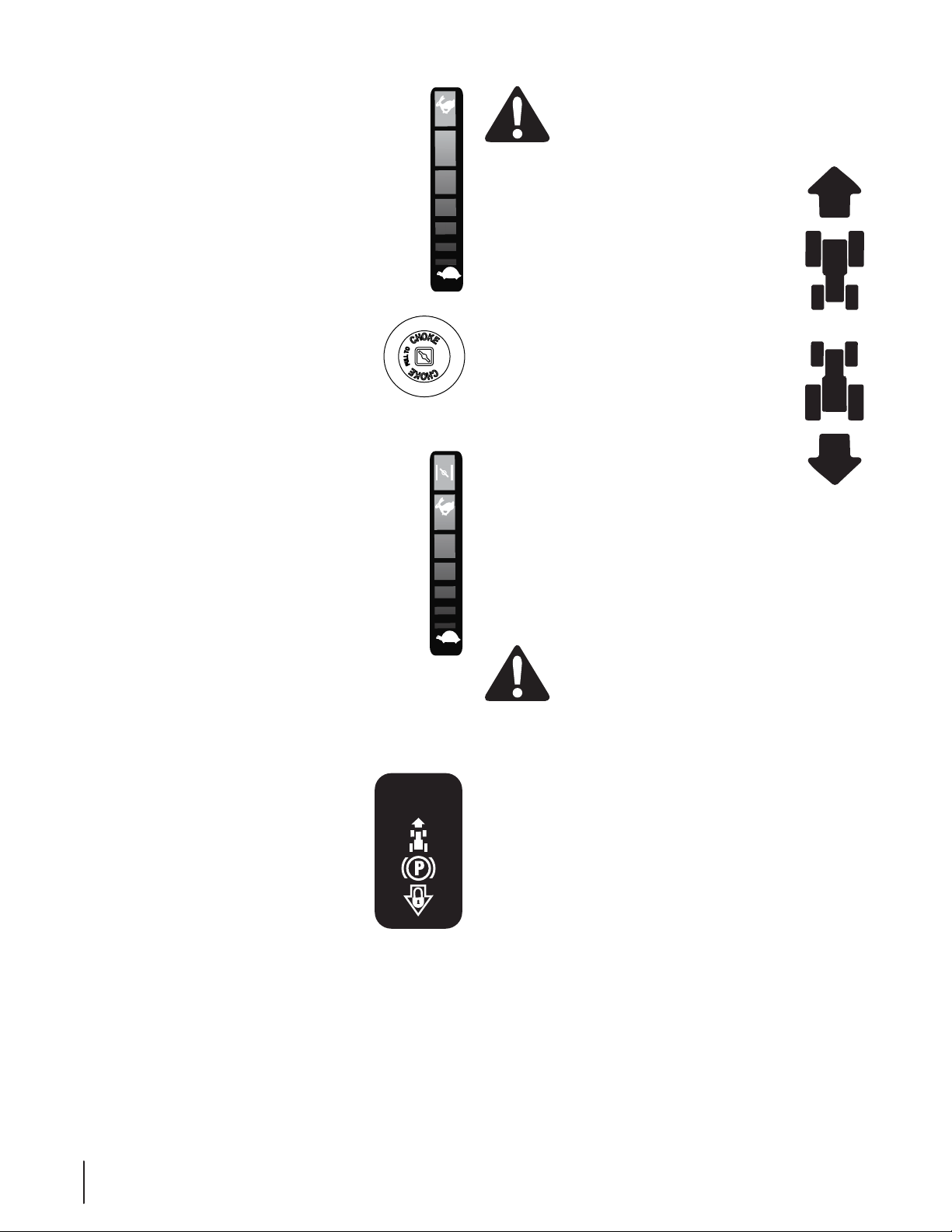
FAST
SLOW
FAST
SL
OW
Throttle Control
The throttle control is located on the RH console to the
left of the hour meter/indicator panel. When set in a given
position, a uniform engine speed will be maintained.
Push the throttle control handle forward to increase the
engine speed. The tractor is designed to operate with the
throttle control in the fast position (full throttle) when the
tractor is being driven and the mower deck is engaged.
Pull the throttle control handle rearward to decrease the
engine speed.
Choke Control (If so equipped)
The choke control is located on the RH console to
the right of the hour meter/indicator panel .The
choke control determines the position of the engine
choke. Pull the knob out to choke the engine; push
the knob in to open the choke.
Throttle/Choke Control (If so equipped)
The throttle/choke control is located on the RH console
to the left of the hour meter/indicator panel. When
set in a given position, a uniform engine speed will be
maintained.
• Push the throttle/choke control handle forward to
increase the engine speed. The tractor is designed
to operate with the throttle/choke control in the
fast position (full throttle) when the tractor is being
driven and the mower deck is engaged.
• Pull the throttle/choke control handle rearward to
decrease the engine speed.
• When starting the engine, push the control handle fully
forward into the “CHOKE” position.
• After starting and warming the engine, move the control
handle rearward until you feel it move past the choke
detent.
Parking Brake/
Cruise Control Lock Pedal
The parking brake/cruise control lock pedal is
located at the base of the steering column. It
is used to engage the parking brake when the
tractor is at rest. Engaging the lever while the
tractor is in motion allows the tractor to remain
at a constant ground speed without applying
pressure to the forward drive pedal. Refer to
the Operation section of this manual for detailed instructions
regarding the parking brake as well as the cruise control feature.
NOTE: Cruise control can NOT be engaged at the tractor’s
fastest ground speed. If the operator should attempt to do so,
the tractor will automatically decelerate to the fastest optimal
mowing ground speed
NOTE: The parking brake must be set if the operator leaves the
seat with the engine running or the engine will automatically
shut off.
PARK BRAKE/
CRUISE CTRL .
LOCK PEDA L
I23746
WARNING! Never leave a running machine
unattended. Always disengage PTO, set parking
brake, stop engine and remove key to prevent
unintended starting.
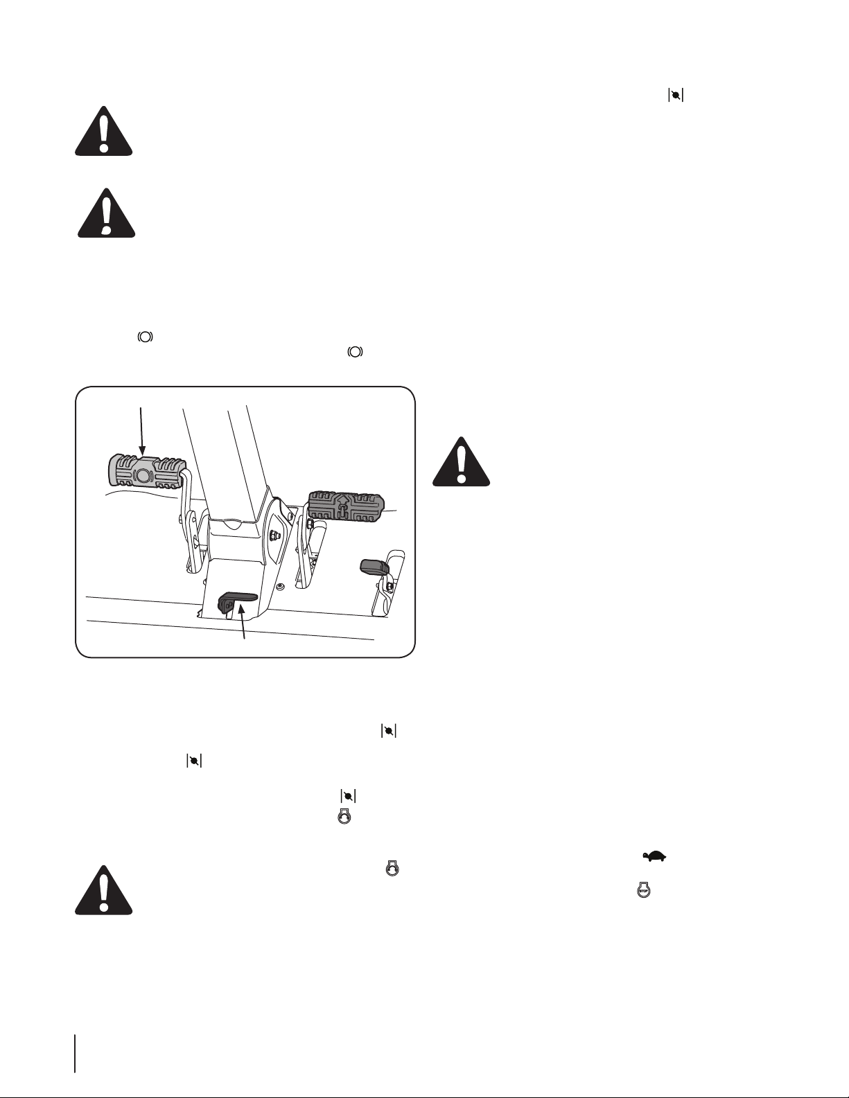
Forward Drive Pedal
The forward drive pedal is located on the right side
of the tractor, along the running board. Press the
forward drive pedal forward to cause the tractor to
travel forward. Ground speed is also controlled with
the forward drive pedal. The further forward the
pedal is pivoted, the faster the tractor will travel. The
pedal will return to its original position when it’s not
pressed.
Reverse Pedal
The reverse drive pedal is located on the right side of
the tractor along the running board. Ground speed
is also controlled with the reverse drive pedal. The
further downward the pedal is pivoted, the faster the
tractor will travel. The pedal will return to its original
position when it’s not pressed.
Transmission Bypass Rods
The transmission bypass rods (one for each the RH and LH
transmission) are located on the rear of the tractor, just inside
each rear wheel.
When engaged, the two rods open a bypass within the
hydrostatic transmissions, which allows the tractor to be pushed
short distances by hand. Refer to the Assembly & Set-Up section
for instructions on using the bypass feature.
CAUTION: Never tow your tractor. Towing the
tractor with the rear wheels on the ground may
cause severe damage to the transmissions.
Cup Holder
The cup holder is located on the RH console to the right of the
operator’s seat.
Storage Tray
The storage tray is located at the rear of the RH console.
Seat Adjustment Lever
The seat adjustment lever is located below the left side of the
seat. The lever allows for adjustment of the fore to aft position of
the operator’s seat. Refer to the Assembly & Set-Up section for
instructions on adjusting the seat position.
14 Section 4— controlS & FeatureS

Operation
5
General Safety
• RECEIVE INSTRUCTION — Entirely read this operator’s
manual. Learn to operate this machine SAFELY. Do not risk
INJURY or DEATH. Allow only those who have become
competent in its usage to operate this tractor.
• Before starting the engine or beginning operation, be
familiar with the controls. The operator should be in the
operator’s seat. The PTO switch must be in the disengaged
position and the parking brake engaged.
• Keep all shields in place. Keep away from moving parts.
• NO RIDERS! Keep all people and pets a safe distance away.
Look behind and down to both sides of the tractor before
and while backing up.
• DO NOT direct the mower discharge at people.
• Avoid slopes where possible. Never operate on slopes
greater than 15°. Slopes with a greater incline present
dangerous operating conditions. Tractors can be rolled over.
• Before leaving the operator’s seat shut off the PTO and
engage the parking brake, shut off the engine and remove
the ignition key. Wait for all movement to stop before
servicing or cleaning.
• Avoid any sudden movements of the steering wheel when
starting and stopping. Keep a firm grip on the steering wheel.
• Be careful when operating near roadways. Stop the tractor
motion and wait for vehicles to pass before operating
along the road.
• Do not operate the tractor with the mower deck removed.
Removal of the deck will change the balance of the tractor,
and could contribute to a tractor rollover.
• Avoid operation on traction surfaces that are unstable; use
extreme caution if the surface is slippery.
• Slow down before turning and come to a complete stop
before any zero turn maneuver.
• Do not stop the tractor or park the tractor over
combustible materials such as dry grass, leaves, debris, etc.
• Do not fill the fuel tank when the engine is running or
while the engine is hot. Allow the engine several minutes
to cool before refueling. Tighten the fuel cap securely.
Before Operating Your Tractor
• Before you operate the tractor, study this manual carefully
to familiarize yourself with the operation of all the
instruments and controls. It has been prepared to help you
operate and maintain your tractor efficiently.
• This engine is certified to operate only on clean, fresh,
unleaded regular gasoline. For best results, fill the fuel
tank with only clean, fresh, unleaded gasoline with a pump
sticker octane rating of 87 or higher.
• Unleaded gasoline is recommended because it leaves
less combustion chamber deposits and reduces harmful
exhaust emissions. Leaded gasoline is not recommended
and must not be used where exhaust emissions are
regulated.
NOTE: Purchase gasoline in small quantities. Do not use
gasoline left over from the previous season, to minimize
gum deposits in the fuel system.
• Gasohol (up to 10% ethyl alcohol, 90% unleaded gasoline
by volume) is an approved fuel. Other gasoline/alcohol
blends are not approved.
• Methyl Tertiary Butyl Ether (MTBE) and unleaded gasoline
blends (up to a maximum of 15% MTBE by volume) are
approved fuels. Other gasoline/ether blends are not
approved.
• Check the engine oil level.
• Clean the air cleaner element if necessary.
• Check the tire inflation pressures.
• Adjust the seat for operator’s maximum comfort, visibility
and for maintaining complete control of the tractor.
Safety Interlock Switches
This tractor is equipped with a safety interlock system for the
protection of the operator. If the interlock system should ever
malfunction, do not operate the tractor. Contact your Cub Cadet
dealer.
• The safety interlock system prevents the engine from
cranking or starting unless the parking brake is engaged,
and the PTO knob is in the disengaged (OFF) position.
• The engine will automatically shut off if the operator leaves
the seat before engaging the parking brake.
WARNING! Do not operate the tractor if the
interlock system is malfunctioning. This system was
designed for your safety and protection.
15
Starting the Engine
Brake Pedal
Parking Brake/Cruise Control Lever
WARNING! This tractor is equipped with a safety
interlock system designed for the protection of the
operator. Do not operate the tractor if any part of the
system is malfunctioning. Periodically check the
function of the interlock system for proper operation.
WARNING! For personal safety, the operator must
be sitting in the tractor seat when starting the
engine.
NOTE: Refer to the Engine Operator’s Manual for oil fill-up
instructions and refer to the Assembly & Set-Up section for
gasoline fill-up instructions.
1. Operator must be sitting in the tractor seat.
2. Engage the parking brake by pressing forward on the brake
pedal , then press down on the parking break/cruise
control lever and then release the brake pedal . Refer to
Figure 5-1.
Figure 5-1
3. Make certain the PTO switch is in the disengaged (down)
position. Refer to Figure 5-1.
4. Pull the choke knob (if equipped) up into the CHOKE
position or move the throttle/choke control (if equipped)
into the CHOKE position.
NOTE: If the engine is warmed up, it may not be necessary to
place the throttle/choke control in the CHOKE position.
5. Turn the ignition key clockwise to the START position.
After the engine starts, release the key. It will return to the
run position.
CAUTION: Do NOT hold the key in the START
position for longer than ten seconds at a time. Doing
so may cause damage to your engine’s electric
starter.
6. As the engine warms up, gradually pull the throttle/choke
control lever (if equipped) rearward past the choke detent
position or push the choke knob (if equipped) down into
the OFF position.
NOTE: Do NOT leave the throttle/choke control (if equipped)
or the choke (if equipped) in the CHOKE position while
operating the tractor. Doing so will result in a “rich” fuel
mixture and cause the engine to run poorly.
7. Allow the engine to run for a few minutes at mid throttle
before putting the engine under load.
8. Observe the hour meter/indicator panel. If the battery indicator
light or oil pressure light come on, immediately stop the engine.
Have the tractor inspected by your Cub Cadet dealer.
Cold Weather Starting
When starting the engine at temperatures near or below freezing,
ensure the correct viscosity motor oil is used in the engine and the
battery is fully charged. Start the engine as follows:
1. Be sure the battery is in good condition. A warm battery
has much more starting capacity than a cold battery.
2. Use fresh winter grade fuel. Winter grade gasoline has
higher volatility to improve starting. Do not use gasoline
left over from summer.
3. Follow the previous instruction for Starting the Engine.
Using Jumper Cables To Start Engine
WARNING! Batteries contain sulfuric acid and
produce explosive gasses. Make certain the area is
well ventilated, wear gloves and eye protection, and
avoid sparks or flames near the battery.
If the battery charge is not sufficient to crank the engine,
recharge the battery. If a battery charger is unavailable and
the tractor must be started, the aid of a booster battery will be
necessary. Connect the booster battery as follows:
1. Connect the end of one cable to the disabled tractor
battery’s positive terminal; then connect the other end of
that cable to the booster battery’s positive terminal.
2. Connect one end of the other cable to the booster
battery’s negative terminal; then connect the other end of
that cable to the frame of the disabled tractor, as far from
the battery as possible.
3. Start the disabled tractor following the normal starting
instructions previously provided; then disconnect the
jumper cables in the exact reverse order of their connection.
4. Have the tractor’s electrical system checked and repaired
as soon as possible to eliminate the need for jump starting.
Stopping the Engine
1. Place the PTO switch in the disengaged position.
2. Engage the parking brake.
3. Move the throttle/choke control (if equipped) or the
throttle (if equipped) to the SLOW position and allow
the engine to idle for about one minute.
4. Turn the ignition key to the STOP position and remove
the key from the ignition switch.
NOTE: Always remove the key from the ignition switch to prevent
accidental starting or battery discharge if the equipment is left
unattended.
Section 5— operation16
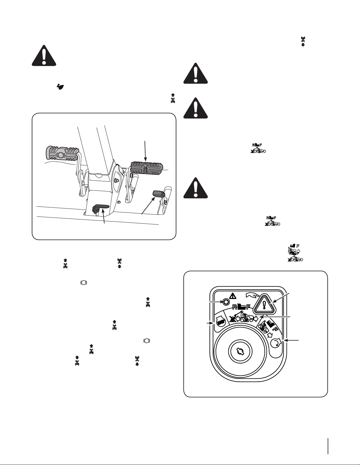
Driving The Tractor
Forward Drive Pedal
Reverse Drive Pedal
Parking Brake/Cruise Control Lever
Indicator
Light
Reverse
Push Button
Stop
Position
Start
Position
Reverse
Caution Mode
Position
WARNING! Avoid sudden starts, excessive speed
and sudden stops.
1. Release the parking brake. Move the throttle/choke control
lever (if equipped) or the throttle (if equipped) into the
FAST position.
2. To travel FORWARD, slowly press the forward drive pedal
forward until the desired speed is achieved. See Figure 5-2.
6. To travel in reverse, check that the area behind is clear then
slowly push forward on the reverse drive pedal with the
ball of your foot (NOT your heel) until the desired speed is
achieved. See Figure 5-2.
CAUTION: Do NOT attempt to change the
direction of travel when the tractor is in motion.
Always bring the tractor to a complete stop before
moving the tractor from forward to reverse or vice
versa.
WARNING! Do not leave the seat of the tractor
without first placing the PTO knob in the
disengaged (OFF) position and engaging the
parking brake. If leaving the tractor unattended, also
turn the engine off and remove the ignition key.
Reverse Caution Mode
The REVERSE CAUTION MODE position of the key switch
module allows the tractor to be operated in reverse with the
blades (PTO) engaged.
NOTE: Mowing in reverse is not recommended.
WARNING! Use extreme caution while operating
the tractor in the REVERSE CAUTION MODE. Always
look down and behind before and while backing. Do
not operate the tractor when children or others are
around. Stop the tractor immediately if someone
enters the area.
Figure 5-2
3. To stop or slow down the tractor, take your foot off of the
forward or reverse drive pedal . To lock the parking
brake, press forward on the brake pedal, then press down
on the parking break/cruise control lever and then release
the brake pedal .
4. To use the cruise control:
a. Press down on the forward drive pedal .
b. While maintaining the desired speed press down on
the parking break/cruise control lever then release
the forward drive pedal to activate the cruise
control.
5. To release the cruise control, press the brake or the
forward drive pedal .
NOTE: The forward and reverse drive pedals must not be
used when the brake is partially engaged. When the brake is
locked the drive belt is disengaged but if the brake is only part
way back then the brakes are engaged but so is the drive belt so
transmission damage will occur if you push forward or reverse.
To use the REVERSE CAUTION MODE :
NOTE: The operator MUST be seated in the tractor seat.
1. Start the engine as instructed on the previous page.
2. Turn the key from the NORMAL MOWING (Green)
position to the REVERSE CAUTION MODE (Yellow)
position of the key switch module. See Figure 5-3.
Figure 5-3
Section 5 — oper ation 17
3. Press the REVERSE PUSH BUTTON (Orange, Triangular
ON
OFF
Button) at the top, right corner of the key switch module.
The red indicator light at the top, left corner of the key
switch module will be ON while activated. See Figure 5-3.
4. Once activated (indicator light ON), the tractor can be
driven in reverse with the cutting blades (PTO) engaged.
5. Always look down and behind before and while backing to
make sure no children are around. After resuming forward
motion, return the key to the NORMAL MOWING
position.
The REVERSE CAUTION MODE will remain activated until:
a. The key is placed in either the NORMAL MOWING
position or STOP position or
b. The operator leaves the seat.
Driving On Slopes
Refer to the SLOPE GAUGE on page 8 to help determine slopes
where you may operate the tractor safely.
WARNING! Do not mow on inclines with a slope in
excess of 15 degrees (a rise of approximately 2-⁄
feet every 10 feet). The tractor could overturn and
cause serious injury.
• Mow across slopes, not up and down.
• Exercise extreme caution when changing direction on
slopes.
• Watch for holes, ruts, bumps, rocks, or other hidden
objects. Uneven terrain could overturn the machine. Tall
grass can hide obstacles.
• Do not turn on slopes unless necessary; then turn slowly
uphill and use extra care while turning. Turning up a slope
greatly increases the chance of a rollover.
• Avoid stopping when driving up a slope. If it is necessary
to stop while driving up a slope, start up smoothly and
carefully to reduce the possibility of flipping the tractor
over backward.
• Always operate the tractor with the throttle in the FAST
position while mowing.
• For best results it is recommended that the first two laps be
cut with the discharge thrown towards the center. After the
first two laps, reverse the direction to throw the discharge
to the outside for the balance of cutting. This will give a
better appearance to the lawn.
• Do NOT attempt to mow heavy brush and weeds or
extremely tall grass. Your tractor is designed to mow lawns,
NOT clear brush.
• Keep the blades sharp and replace the blades when worn.
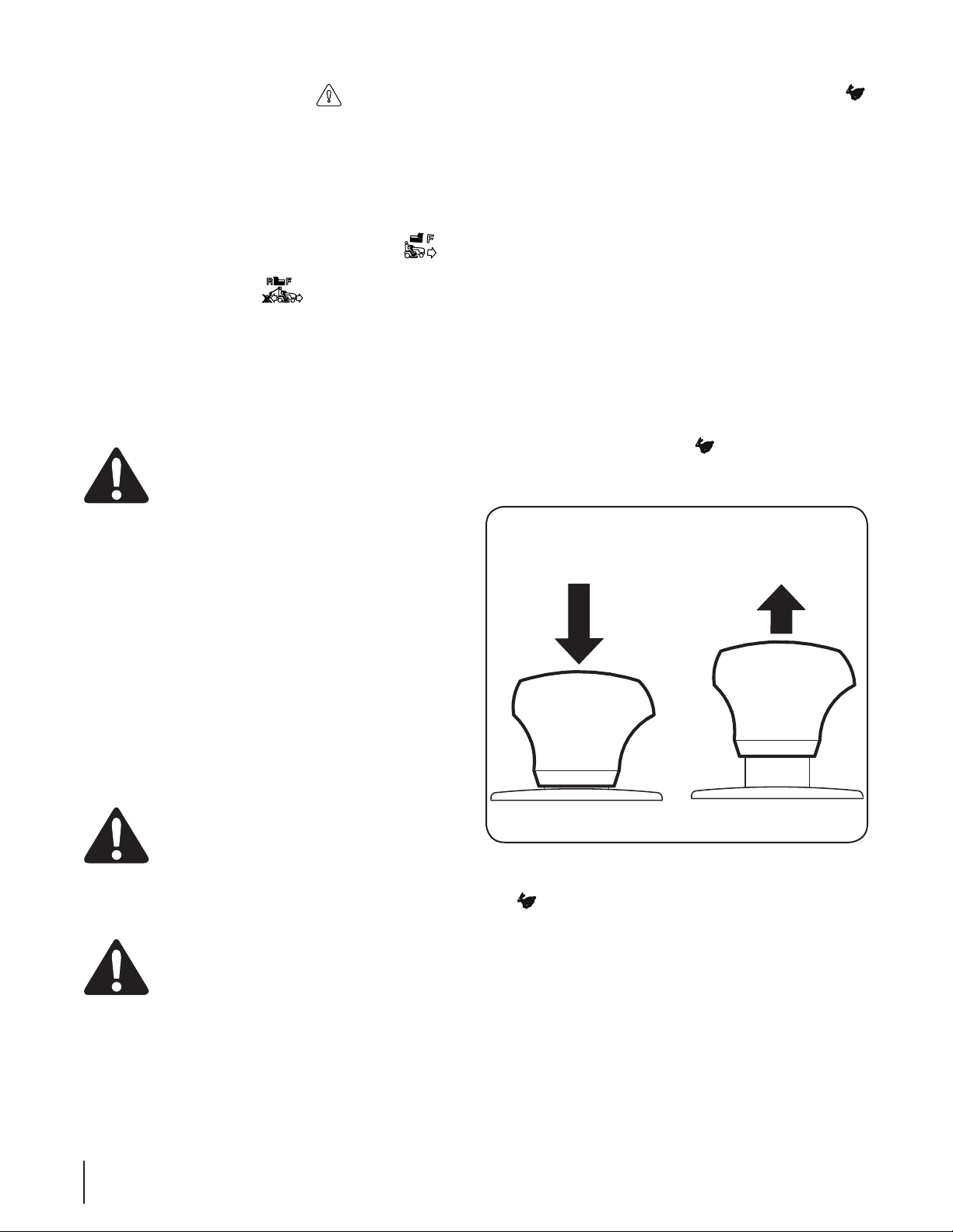
Manual Lift Lever
To raise or lower the cutting deck, move the lift lever to the left,
then place it in the notch best suited for your application.
Engaging the PTO
Engaging the PTO transfers power to the cutting deck or other
(separately available) attachments. To engage the PTO:
1. Move the throttle to the FAST position.
2. Pull the PTO/Blade Engage knob outward into the engaged
(ON) position. See Figure 5-4.
Mowing
WARNING! To help avoid blade contact or a
thrown object injury, keep bystanders, helpers,
children and pets at least 75 feet from the machine
while it is in operation. Stop machine if anyone
enters the area.
The following information will be helpful when using the cutting
deck with your tractor.
• Do not mow at high ground speed, especially if a mulch kit
• Do not cut the grass too short. Short grass is prone to weed
WARNING! Plan your mowing pattern to avoid
discharge of materials toward roads, sidewalks,
bystanders and the like. Also, avoid discharging
material against a wall or obstruction which may
cause discharged material to ricochet back toward
the operator.
or grass collector is installed.
growth and yellows quickly in dry weather.
Section 5— operation18
Figure 5-4
NOTE: Always operate the tractor with the throttle lever in the
FAST position for the most efficient use of the cutting deck or
other (separately available) attachments.

Maintenance & Adjustments
Maintenance Schedule
6
Before
Each use
Clean Battery Terminals
Lube Front Caster Wheels and Wheel Spindles
Check Engine Cooling Fins for Debris (Clean as
Necessary)
Lube Pedal Pivot Points
Grease Front Castings
NOTE: This Operator’s Manual covers several models. Tractor
features may vary by model. Not all features in this manual are
applicable to all tractor models and the tractor depicted may
differ from yours.
P P
Maintenance
WARNING! Before performing any maintenance or
repairs, disengage the PTO, move the drive control
levers fully outward in the neutral position, engage
the parking brake, stop the engine and remove the
key to prevent unintended starting.
Engine
Refer to the Engine Manual for all engine maintenance intervals,
procedures, specifications and instructions.
NOTE: Maintenance, repair, or replacement of the emission
control devices and systems which are being done at owner’s
expense may be performed by any engine repair establishment
or individual. Warranty repairs must be performed by a
dealer.
Battery
CALIFORNIA PROPOSITION 65 WARNING!
Battery posts, terminals, and related accessories
contain lead and lead compounds, chemicals known
to the State of California to cause cancer and
reproductive harm. Wash hands after handling.
The battery is sealed and is maintenance-free. Acid levels cannot
be checked and fluid can not be added.
• Always keep the battery cables and terminals clean and
free of corrosive build-up.
• After cleaning the battery and terminals, apply a light coat
of petroleum jelly or grease to both terminals.
Every
10 Hours
Every
25 Hours
Prior
to Storing
P P
P P
P P
P
CAUTION: If removing the battery for cleaning,
disconnect the NEGATIVE (Black) wire from its terminal
first, followed by the POSITIVE (Red) wire. When reinstalling the battery, always connect the POSITIVE
(Red) wire its terminal first, followed by the NEGATIVE
(Black) wire. Be certain that the wires are connected to
the correct terminals; reversing them could result in
serious damage to your engine’s alternating system.
Battery Storage
1. When storing the tractor for extended periods, disconnect the
negative battery cable. It is not necessary to remove the battery.
2. All batteries discharge during storage. Keep the exterior
of the battery clean, especially the top. A dirty battery will
discharge more rapidly.
3. The battery must be stored with a full charge. A discharged
battery can freeze sooner than a charged battery. A fully
charged battery will store longer in cold temperatures than hot.
4. Recharge the battery before returning to service. Although
the tractor may start, the engine charging system may not
fully recharge the battery.
Tractor Storage
If your tractor is not going to be operated for an extended period
of time (thirty days to approximately six months), the tractor should
be prepared for storage. Store the tractor in a dry and protected
location. If stored outside, cover the tractor (including the tires) to
protect it from the elements. The procedures outlined below should
be performed whenever the tractor is placed in storage.
1. Change the engine oil and filter following the instructions
provided in the engine manual packed with this manual.
WARNING! Never store the tractor with fuel in the
tank indoors or in poorly ventilated enclosures, where
fuel fumes may reach an open flame, spark or pilot
light as on a furnace, water heater, clothes dryer, etc.
19
2. If storing the tractor for 30 days or more:
Nozzle Adapter
Adapter Lock Collar
Deck Wash Nozzle
a. To prevent gum deposits from forming inside
the engine’s carburetor and causing possible
malfunction of the engine, the fuel system must be
either completely emptied, or the gasoline must be
treated with a stabilizer to prevent deterioration.
WARNING! Fuel left in the fuel tank deteriorates
and will cause serious starting problems.
Using a fuel stabilizer such as STA-BIL® for storage
between 30 and 90 days:
• Read the product manufacturer’s instructions
and recommendations.
• Add to clean, fresh gasoline the correct
amount of stabilizer for the capacity
(approximately 3 gallons) of the fuel system.
• Fill the fuel tank with treated fuel and run the
engine for 2-3 minutes to get stabilized fuel
into the carburetor.
b. Emptying the fuel system for storage of more than
90 days:
• Prior to putting the tractor in storage, monitor
fuel consumption with the goal of running
the fuel tank empty.
• Run the engine until it begins to stall. Use the
choke to keep the engine running until all fuel
in the carburetor has been exhausted.
• Referring to the engine manual, drain the fuel
from the carburetor bowl.
3. Clean the engine and the entire tractor thoroughly.
4. Fully charge the battery, then disconnect the negative
cable at the battery to prevent possible discharge.
Recharge the battery periodically when in storage.
NOTE: Remove the battery if exposed to prolonged periods
of sub-freezing temperatures. Store in a cool, dry location
where temperatures are above freezing.
5. Lubricate all lubrication points.
NOTE: Using a pressure washer or garden hose is not
recommended for cleaning your tractor. It may cause
damage to electrical components, spindles, pulleys,
bearings or the engine. The use of water will result in
shortened life and reduce serviceability.
Removing The Tractor From Storage
1. Check the engine oil.
2. Fully charge the battery and inflate the tires to the
recommended pressure.
3. If drained before storing, fill the fuel tank with clean, fresh
gasoline.
4. Add clean, fresh fuel.
5. Start the engine and allow to idle for a few minutes to
ensure engine is operating properly.
6. Drive the tractor without a load to make certain all the
tractor systems are functioning properly.
Cleaning the Tractor
Any fuel or oil spilled on the machine should be wiped off
promptly. Do NOT allow debris to accumulate around the cooling
fins of the engine, the transmission’s cooling fan or on any other
part of the machine, especially the belts and pulleys.
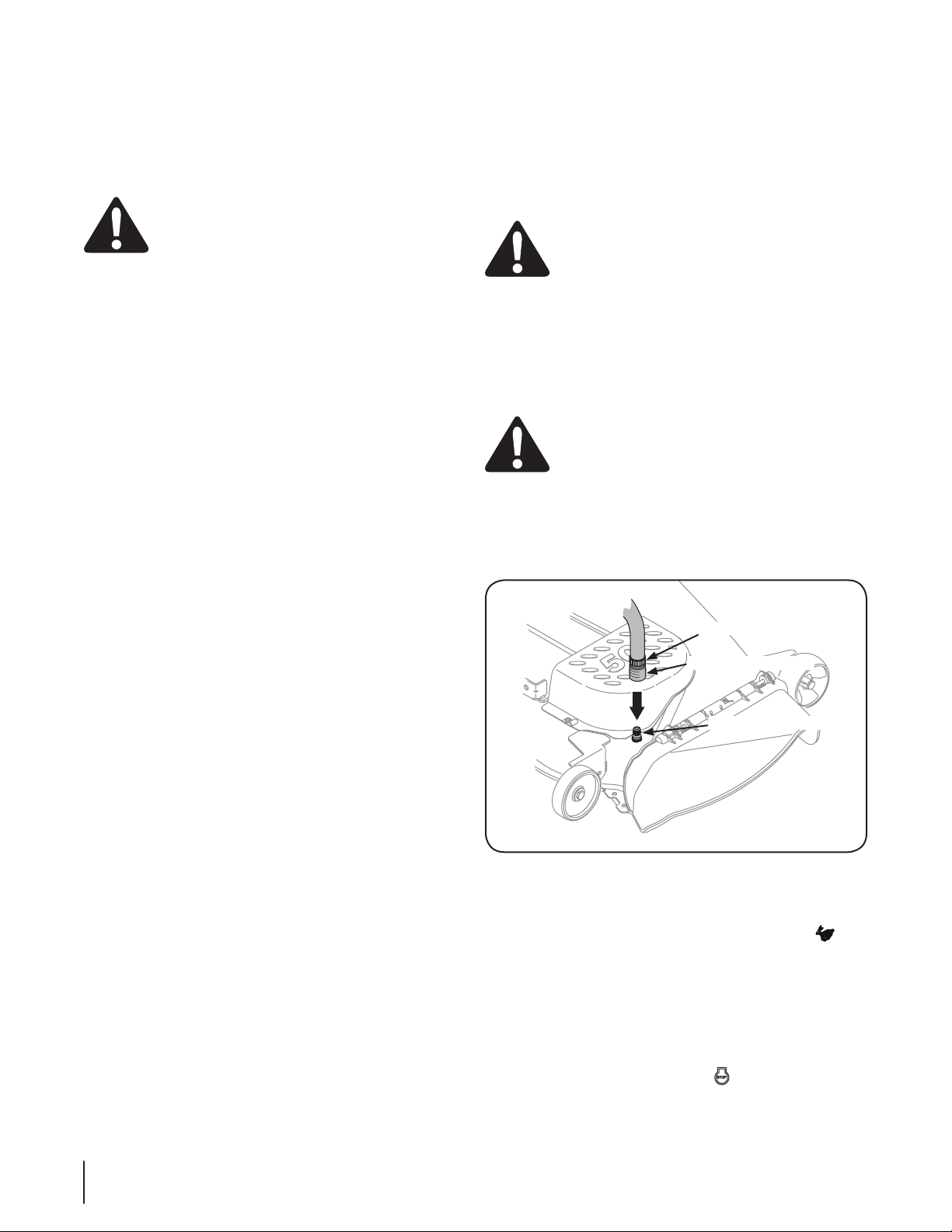
Using the Deck Wash System
WARNING! When using the deck wash system, never
engage the deck from any position other than the
operator’s seat of the tractor. Do not use an assistant or
engage deck in the presence of any bystanders.
1. Attach the nozzle adapter to a standard garden hose
connected to a water supply.
2. Move the tractor to a level clear area within reach of
the hose where the dispersal of wet grass clippings is
acceptable to you. Disengage the PTO, engage the parking
brake and stop the engine.
CAUTION: Make certain the tractor’s discharge
chute is directed AWAY from your house, garage,
parked cars, etc.
3. Pull back the lock collar of the nozzle adapter and push the
adapter onto one of the deck wash nozzles at either end of
the mower deck. Release the lock collar to lock the adapter
on the nozzle. See Figure 6-1 .
Figure 6-1
4. Turn the water on.
5. While sitting in the operator’s position on the tractor, start
the engine and place the throttle lever in the FAST
position.
6. Engage the PTO.
7. Remain in the operator’s position with the cutting deck
engaged for a minimum of two minutes, allowing the
underside of the cutting deck to thoroughly rinse.
8. Disengage the PTO.
9. Turn the ignition key to the STOP position to turn the
tractor’s engine off.
20
Section 6— Maintenance & adjuStMentS

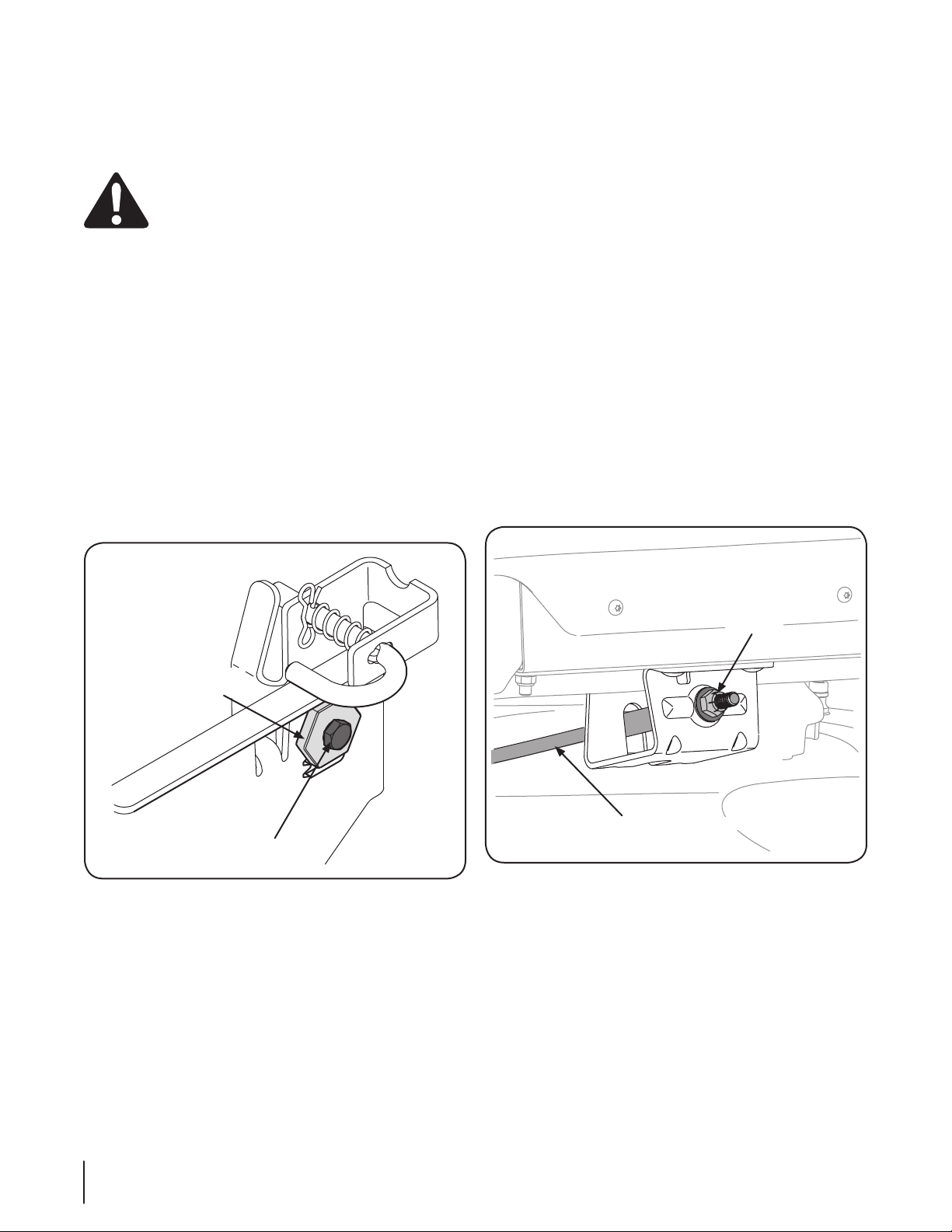
Grease
Fitting
10. Turn the water off and detach the hose coupler from the
Grease
Fittings
water port on your deck’s surface.
11. After cleaning your deck, return to the operator’s position
and engage the PTO. Keep the cutting deck running for a
minimum of two minutes, allowing the underside of the
cutting deck to thoroughly dry.
Lubrication
WARNING! Before lubricating, repairing, or
inspecting, always disengage PTO, set parking
brake, stop engine and remove key to prevent
unintended starting.
Front Wheels
Each of the front wheel spindles and rims is equipped with a grease
fitting. See Figure 6-2. Lubricate with a No. 2 multi-purpose grease
applied with a grease gun after every 25 hours of tractor operation.
Steering Supports
Under the frame of the tractor there are two grease fittings for
the steering supports. Lubricate with a No. 2 multi-purpose
grease applied with a grease gun after every 25 hours of tractor
operation. See Figure 6-3.
Figure 6-3
Figure 6-2
Pivot Points & Linkage
Lubricate all the pivot points on the drive system, parking brake
and lift linkage at least once a season with light oil.
Tires
Check the tire air pressure after every 50 hours of operation or
weekly. Keep the tires inflated to the recommended pressures.
Improper inflation will shorten the tire service life. See the tire
side wall for proper inflation pressures. Observe the following
guidelines:
WARNING! Never exceed the maximum inflation
pressure shown on the sidewall of the tire.
Do not reinflate a tire that has been run flat or seriously under
inflated. Have it inspected and serviced by a qualified tire
mechanic.
Section 6 — Maintenance & adjuStMentS
21
Adjustments
Adjustment
Gear
Hex Bolt
Lock Nut
Front Deck Lift Rod
NOTE: Check the tractor’s tire pressure before performing
any deck leveling adjustments. Refer to Tires for information
regarding tire pressure.
WARNING! Shut the engine off, remove the
ignition key and engage the parking brake before
making adjustments. Protect your hands by using
heavy gloves when handling the blades.
Leveling the Deck (Side to Side)
NOTE: Check the tractor’s tire pressure before performing any
deck leveling adjustments. Refer to Tires for information regarding
tire pressure. Always level the deck side to side before front to rear.
If the cutting deck appears to be mowing unevenly, a side to side
adjustment can be performed. Adjust if necessary as follows:
1. With the tractor parked on a firm, level surface, place the
deck lift handle in a middle mowing position and rotate both
outside blades so that they are perpendicular with the tractor.
2. Measure the distance from the outside of the left blade
tip to the ground and the distance from the outside of the
right blade tip to the ground. Both measurements taken
should be equal. If they’re not, proceed to the next step.
3. Loosen, but do NOT remove, the hex bolt on the rear left
deck hanger link. See Figure 6-4.
Leveling the Deck (Front To Rear)
NOTE: Check the tractor’s tire pressure before performing
any deck leveling adjustments. Refer to Tires on page 22 for
information regarding tire pressure. Always level the deck side to
side before front to rear.
The front of the deck should be between ⁄” and ⁄” lower than
the rear of the deck. Adjust if necessary as follows:
1. Park the tractor on a firm, level surface and place the deck
lift handle in a middle position.
2. Rotate the blade nearest the discharge chute so that it is
parallel with the tractor.
3. Measure the distance from the front of the blade tip to the
ground and the rear of the blade tip to the ground. The
first measurement taken should be between ⁄” and ⁄” less
than the second measurement.
4. Determine the approximate distance necessary for proper
adjustment and proceed, if necessary.
5. Using a wrench, raise or lower the front of deck by turning
lock nut on the front deck lift rod. See Figure 6-5. The deck
is properly leveled when the front tip of the blade is ⁄”
lower than the rear tip. Retighten the hex bolt on the left
and right rear deck hanger links when proper adjustment
is achieved.
Figure 6-4
NOTE: The rear right deck hanger link is not adjustable and
is used to help adjust the other hanger links.
4. Using a wrench, raise or lower the left side of the deck by
turning the adjustment gear. See Figure 6-5.
The deck is properly leveled when both blade tip measurements
are equal. Retighten the hex bolt on the front left deck hanger
bracket when proper adjustment is achieved.
22
Section 6— Maintenance & adjuStMentS
Figure 6-5
 Loading...